Embed Size (px)
Citation preview

Strobe Data, Inc January 17, 2003 Redmond, WA USA
Osprey
User’s Manual

January 17, 2003
TABLE OF CONTENTS Manual Information............................................................................... 1
Product Overview.................................................................................. 3
Installation ............................................................................................. 7
PC Software Utilities............................................................................. 17
Startup .................................................................................................... 21
OSPREY.CHK Diagnostic ................................................................... 25
Configuration......................................................................................... 27
Osprey Control Menu(NT) ...................................................................... 92
Osprey Control Menu(DOS) .................................................................... 99
Strobe ODT............................................................................................ 103
Container File Builder........................................................................... 107
Filetape................................................................................................... 113
KEYNAME........................................................................................... 117
VT100 Configuration File..................................................................... 119
Screen Modes ........................................................................................ 125
GETDISK .............................................................................................. 129
DOSLink and Strobe File Exchange .................................................... 131
Cross Assembler.................................................................................... 131
Appendix A: LSRMST ......................................................................... 131

January 17, 2003
Appendix B: Host CPU Loading.......................................................... 131

January 17, 2003

Manual Information
January 17, 2003 Osprey User's Manual -- Page 1
MANUAL INFORMATION Examples in the middle of the text (like this) will be set off in special type.
This document applies to the all versions of the Osprey coprocessor and the two operating systems that it runs under. The versions include the Osprey, Osprey/ISA, and Osprey/PCI. The two
operating systems are DOS and NT. There are a few differences between the Osprey/DCJ11, the Osprey/ISA, and the Osprey/PCI. There are also a few differences between DOS and NT. When something applies only to one
version, a superscript notation will indicate the version. For example: X86CPU = {Generic DX}(ISA)
X86CPU = {TI TI2 TIF TI2F INTEL IBM}(DCJ11) PriorityClass = {Idle Normal High RealTime}(NT)
The Osprey uses several default filenames. If you rename the OSPREY.EXE file, those default names change to the same base name as the OSPREY.EXE was renamed to.
The following files will change from a base name of OSPREY to the same base name of the .EXE file.
Filename Defined on page OSPREY.X86 40 OSPREY.J11 34 OSPREY.BIN 30 OSPREY.CNF 28 OSPREY.CLD 31 OSPREY.FWQ 32 OSPREY.FWU 32 OSPREY.UCO 38 OSPREY.IOT 33 OSPREY.PRM 36 OSPREY.EEP 32 OSPREY.UMR 39
For example, if you rename OSPREY.EXE to STROBE.EXE then the default filenames will be STROBE.X86, STROBE.J11, etc. Since this name change affects only the default name, there will
be no effect if the configuration file contains a specific call to a file. That means J11File = OSPREY.J11 is unaffected and still looks for OSPREY.J11 in spite of what the .EXE is named. The files must reside in the .EXE file directory, the current directory, a directory listed in the
OSPREY environment variable, or in the PATH. The Osprey searches for its files in that order.

Manual Information
January 17, 2003 Osprey User's Manual -- Page 2

Product Overview
January 17, 2003 Osprey User's Manual -- Page 3
PRODUCT OVERVIEW The Osprey Co-Processor is a PC add-in card, which allows any standard ISA, EISA, or PCI based
PC to replace a Digital Equipment Corporation 16-bit PDP minicomputer. The system uses PC hardware devices to replace corresponding minicomputer peripherals in a manner transparent to the
PDP software. Thus PDP operating systems and applications run without modification on the Osprey/PC platform.
Most PDP instructions are executed directly out of local memory by the Osprey’s CPU. Traditional PDP hardware floating point is available through the use of either an optional onboard FPJ11
processor(DCJ11) or through the standard microcode(ISA/PCI). I/O instructions are handled by a local 80X86 microprocessor. This processor serves as the
interface between the host PC software and the Osprey CPU. On the Osprey side, it provides the low level register, status, and interrupt functions which the PDP software expects for each device. On the host side, it provides a high level interface for the routing of I/O requests to the appropriate
host device. Not every PDP device has a counterpart in the PC environment. Also, some devices used in data
collection and process control are not well suited to device emulation. The Osprey board addresses this issue by allowing physical PDP devices to be supported through the use of the Osprey I/O bus
adapter card. This card connects to the main Osprey card and provides the required QBUS or UNIBUS backplane signals in response to I/O instructions executed by the Osprey’s J11 processor. In this configuration, the Osprey hardware is initialized on startup to route specified I/O instructions
to the bus adapter.

Product Overview
January 17, 2003 Osprey User's Manual -- Page 4
The Osprey board is available in several configurations. Board type Speed compared to 11/93 Bus type DCJ11 1.0 ISA SX 1.0 ISA/PCI DX 2.0 ISA/PCI TX 3.0 PCI QX 4.0 PCI

Product Overview
January 17, 2003 Osprey User's Manual -- Page 5


Installation
January 17, 2003 Osprey User's Manual -- Page 7
INSTALLATION
Hardware installation
FCC Class A Radio Frequency Interference Statement Note:
This equipment has been tested and found to comply with the limits for a Class A digital device, pursuant to Part 15 of the FCC rules. These limits are designed to provide reasonable protection against harmful interference when the equipment is operated in a commercial environment. This equipment generates, uses, and can radiate radio frequency energy and, if not installed and used in accordance with the instruction manual, may cause harmful interference to radio communications. Operation of this equipment in a residential area is likely to cause harmful interference in which
case the user will be required to correct the interference at his own expense.
DCJ11 and ISA Installation
New Unibus versus Old Unibus
Starting June 1, 1998, a new Unibus board has been included with Osprey/Unibus systems. You must install the software for the correct board. If you install the wrong software, the HWDIAG
program (see page 11) will fail. Install the correct software and run HWDIAG again. Characteristic Old Boards New Boards Date Before June 1, 1998 June 1, 1998 and after Engraved serial number 9470UB- 9542UB- White sticker on the back None Serial number 9542UB- XILINX part number XC4002A XC4003E Fan / edge connector Plain Orange sticker inside and out Rev on lower left corner Missing or “Rev A” “Rev B” or later

Installation
January 17, 2003 Osprey User's Manual -- Page 8
The Osprey must be plugged into a 16-bit ISA.
By default, the Osprey board uses PC interrupt 2 and PC I/O address range 320-32F. The cards can be configured with interrupt of 2 through 15 and I/O address range from 100 to FF0. Warning: most I/O cards do not decode all ranges up to FF0. Therefore, you should only use 100-3F0 for
your I/O base unless you have detailed knowledge of the I/O decode procedure of your other add in cards. Most I/O cards will cause these ranges to be the same.
Set 1: 0xx 4xx 8xx and Cxx This set is illegal Set 2: 1xx 5xx 9xx and Dxx Set 3: 2xx 6xx Axx and Exx Set 4: 3xx 7xx Bxx and Fxx The Osprey board interrupt is software controlled and can be specified in the configuration file (see
page 32). The interrupt must not be in use by another card in the system. Also, on PCI motherboards, the interrupt must be configured for ISA usage. The device I/O address range is
controlled by onboard DIP switches. The switches form the most significant eight bits of a twelve-bit I/O address. The least significant four bits are always zero. Switches that are down on the open side are read as zero bits. Switches that are up on the open side are read as one bits. The following
diagram shows the default I/O address of 320.
1 2 3 4 5 6 7 8
D D D
D D D D D
Open Cooling is essential to reliability, even longevity, of the Osprey. Make sure your PC has adequate airflow. If your machine has enough slots, leave an empty slot on each side of the Osprey card set
to provide extra cooling.

Installation
January 17, 2003 Osprey User's Manual -- Page 9
PC considerations
We advise our VARs to exercise extreme caution in their selection of PC hosts for Strobe’s line of Co-processors. Strobe suggests the use of only top-line PC’s—those marketed specifically for use
as file servers, for instance. For the full description, please email [email protected] PC considerations(NT)
The host PC for Windows/NT should be at a minimum a 120Mhz Pentium with 32MB of memory and a 512MB hard drive. A high performance PCI video card with a good monitor is highly
recommended (required, really). On such a system, the performance will be nearly identical to the DOS based Osprey running on the
same platform. If additional applications will be running concurrently with the Osprey, then a minimum of a
200Mhz Pentium with 64MB of memory and a 1GB hard drive is recommended.
Monitor considerations(NT)
The software uses dynamic font sizing to find the best fit for a given window size. As you size the window, you will see the screen font adjust. At a minimum, the screen resolution should be 800 x
600 and 1024 x 768 is better. At 800 x 600, each character has only seven pixels in 80 column mode and five pixels in 132 column mode. A five-pixel character is nearly unreadable. At 800 x
600, a 100 line screen (see page 61) also has only five pixels per character.
Software installation Osprey software is delivered on 3½” diskettes. The software requires about 5mb of disk space to
install. Software installation(DOS)
Osprey/DOS requires about 400kb of free conventional memory to run. To install the Osprey software, insert the diskette and run the installation program:
A:\INSTALL The program will prompt for a drive and directory name. Just hit ENTER to accept the default shown inside square brackets. To install the software using default drive and directory name
(C:\OSPREY), just run A:\INSTALL /D. During installation, you will be asked which Osprey model you have. There are four different models: the new Unibus model, the old Unibus model, the
Qbus model, and the single board Osprey with no bus connections. If you answer the question incorrectly, wait until the rest of the installation finishes and run the WHICHBIN program (see page
14) to re-configure.
Software installation (NT) Insert disk 1 and use any one of the standard NT installation methods:
1) Choose Start \ Run \ a:setup.exe 2) Choose Add-Remove Programs from the control panel 3) Click My Computer and then the 3½” floppy. Run setup.exe

Installation
January 17, 2003 Osprey User's Manual -- Page 10
The Osprey/NT software is also available from the Internet at http://www.strobedata.com in the Osprey support section.
The setup program will guide you through the installation process. You will need to know the following information:
• What type of Osprey board you are using (Osprey DCJ11, Osprey/ISA or Osprey/PCI) • What type of I/O adapter you are using (Qbus, Unibus, New Unibus or None) • The I/O address of the board (Hex 320 is the default)(DCJ11/ISA) • The interrupt number you will use for the board(DCJ11/ISA) • If you need the Strobe Data StrobeMux multi-line serial I/O card driver • If you need to access RX50 diskettes using the PC 1.2MB drive • If you need the 3C509 Ethernet card driver for DEQNA emulation • If you need the 3C900B Ethernet card driver for DEQNA emulation • The ID port if you have multiple 3C509 Ethernet cards • If you are using a Boca board multi-line serial card
(DCJ11/ISA)To locate available interrupt and I/O address resources, run the ‘Windows NT Diagnostics’ program from within the ‘Administrative Tools’ program group. Select the ‘Resources’ tab to view
a list of currently active drivers and the interrupts, I/O address, and DMA channels used by each driver.
The StrobeMux driver allows access to the StrobeMux ports via the standard NT COM interface (modem control functions are disabled as the StrobeMux ports do not support modem control signals). You will need to know the interrupt and I/O address of each StrobeMux board and to
ensure that these resources are available. You also need to select a starting COM port number for the serial ports on each board and to specify a 16 or 32 port board.
To support RX50 diskettes in the PC 1.2MB floppy drive, the Osprey/NT package uses a specially modified version of the standard NT floppy driver. You can not use 360Kb diskettes in a 1.2Mb
drive when the Osprey/NT floppy driver is installed. A custom driver is required if you are using a 3COM 3C509 or 3C900B network card to provide
DEQNA emulation. The 3COM 3C509 card must be configured (using 3COM’s DOS based 3C5X9CFG.EXE program) to have the Plug-n-Play feature disabled and the I/O base and interrupt
manually programmed into the card. This is identical to the card setup requirements of the Osprey/DOS system. The 3COM 3C900B network card does not require configuring.
Note that the Osprey/NT 3C509 driver also requires access to a card identification port, which may be any available I/O port numbered 1x0 (hexadecimal), where x represents any hexadecimal digit. The default card identification port is 110 (hexadecimal). If you have one or more other 3C509 cards in the system that are being used by the standard NT network driver, this driver will have
already reserved I/O port 110 for its exclusive use. In this case, the Osprey/NT 3C509 driver will attempt to use a valid, alternate port (140, 130 or 120 hexadecimal) for this purpose. If none of
these alternate ports is available, the Osprey/NT 3C509 driver will not load. To work around this, you can force the driver to use any other valid (1x0 hexadecimal) address for the card identification
port by creating a DWORD registry value named IDPORT under the HKEY_LOCAL_MACHINE\System\CurrentControlSet\Services\Osp3C509\Parameters
registry key and giving it the required port address.

Installation
January 17, 2003 Osprey User's Manual -- Page 11
The Osprey/NT 3C900B driver will not access a 3C900B network card which is in use by the standard NT network driver. To allow Windows NT to use one or more 3C900B cards at the same
time that Osprey/NT uses one or more (different) 3C900B cards, configure the Windows NT network first; Osprey/NT can then use the remaining (unused by Windows) 3C900B cards.
After the software is installed, the NT system must be restarted to load the drivers. If any driver fails to load, NT will display a message directing you to the ‘Event Viewer’ program to see the detailed error descriptions. The ‘Event Viewer’ program is found in the ‘Administrative Tools’
program group.
Getting new versions of the software The most recent versions of Osprey software and utilities are available on the Strobe Data ftp site
and web site. You may also retrieve software, get technical support, or get marketing information via the Internet.
All information is available via the home page. Home Page http://www.strobedata.com/ Anonymous ftp ftp://mail.strobedata.com/ Marketing/sales [email protected] Tech support [email protected]
System verification(DOS) Once the hardware and software have been installed, go to the OSPREY directory and type
HWDIAG. This provides a quick test of all major components and data paths on the Osprey board. A simple board diagnostic will run.
When HWDIAG passes, go to the OSPREY directory and type:
OSPREY /C:EXAMPLE.CNF The Osprey will give you several options. See the section on OSPREY.CHK (page 21) for details
on how to run the diagnostics. If HWDIAG fails with memory tests, and you have a Unibus machine, you may have installed the
wrong Unibus software. See page 7 for information about determining your board type. System verification(NT)
Once the hardware and software have been installed, click Start \ Programs \ Osprey \ Diagnose Hardware (low level). This will run the HWDIAG diagnostic.
Once HWDIAG passes, click Start \ Programs \ Osprey \ Diagnose system (high level)
The Osprey will give you several options. See the section on OSPREY.CHK (page 21) for details on how to run the diagnostics.
PC Hardware installation Standard disk drives, monitors, keyboards, COM ports, parallel ports and networks are used by the
Osprey system.

Installation
January 17, 2003 Osprey User's Manual -- Page 12
(DOS)For most devices, you must not load the device drivers in to your CONFIG.SYS or AUTOEXEC.BAT. The Osprey program uses its own drivers and will conflict with most
manufacturers’ drivers.
ASPI Installation(DOS)
The ASPITAPE option (page 84) requires a SCSI controller with ASPI.SYS installed, and connected to a Digital TZ30 tape drive.
ASPI Installation(NT)
The ASPITAPE option (page 84) and the ASPIDISK option (page 84) require a SCSI controller. The ASPI device can be used whether or not there is an NT driver installed.
To specify the SCSI device unit and controller, the ‘/Unit:<SCSI Unit ID>’ and /Adapter:<SCSIBoard>’ options can only be used if the device has not been claimed by an NT class
driver. If the device has been claimed by an NT class driver, the new ‘/Name:<Device name>’ option must
be used. For example the option ‘/Name:Tape0’ might be used to specify a SCSI tape device claimed by the NT tape class driver and ‘/Name:PhysicalDrive1’ might be used to specify a SCSI
disk claimed by the disk class driver. A utility program, DOSDEV.EXE, has been provided which can be used to display all system
device names by clicking Start \ Programs \ Osprey \ DOSDEV, or using the command line DOSDEV | more. Note that this program displays the device names in the left column; the right
column shows the NT native names which give a better indication of the actual device.
Customer software/data installation
After the system has been verified with HWDIAG and EXAMPLE.CNF, you are ready to move the original PDP-11 software and data to the PC.
Each physical disk on the Digital minicomputer must have a corresponding disk emulation (disk image) on the PC. You can choose MS-DOS files on the hard disk, memory areas, floppy disks,
network files, etc for your disk images. (See the configuration file section beginning on page 27 for a complete description.)
Most typical disk drives can be copied using the GETDISK program. See page 129 for more information.
If you can not use the GETDISK program, you will need to use the standard PDP operating system to copy your files.
Under most circumstances, Digital disk drives are emulated by means of ordinary files. Use the container file builder program ((DOS)CONTAINR) to create an MS-DOS file container file (see page
107). Unfragmented file container files (usually created in a freshly formatted partition) will provide the
best performance, although a fragmented container file will not affect reliability. After all container files have been created by the container file builder ((DOS)CONTAINR), their
names need to be added to the configuration file. (See the Configuration section beginning on page 27 for a complete description.)

Installation
January 17, 2003 Osprey User's Manual -- Page 13
An installer with Osprey Qbus or Unibus board can download the minicomputer software by means of a disk to disk copy using standard PDP operating system utilities. A GETDISK program is also provided with the Osprey software that may copy your disk as well. See page 129 for more details.
See page 8 for Qbus interrupt priority on the Strobe Qbus Chassis. Make sure that the controller you reference for the minicomputer disk is not defined as a virtual
device in the configuration file. Two other methods that may be used to move software are by floppy or by tape. Floppies are
accessible with the configuration line:
FLOPPY /Drive:0 = MSCP /Unit:1 Then put the floppy in drive A: (/Drive:0) and boot DU1. Tapes are accessible with the configuration line:
ASPITAPE = TMSCP /Unit:0 Then put the tape in the Digital TZ30 drive and boot DU0.
Once all customer software and data has been installed on the PC, remember to change the configuration file for normal production use. The Osprey/PC system is then ready to run.
Typical IRQ and I/O bases(DCJ11/ISA) This table is provided as a reference to avoid hardware conflicts when installing the Osprey in a PC
with other I/O cards. IRQ The underlined interrupt number is recommended I/O Most add-in cards can be reconfigured. The I/O port listed is recommended.
Hardware IRQ I/O DMA
Floppy Disk 6 3F0 2
Fixed Disk E 1F0
80x87 Chip D F0
Bus Mouse C
Video 3B0-3DF
PRN1 7 370, 3BC
PRN2 5 270
COM1 4 3F8
COM2 or Mouse 3 2F8
COM3 7 3E8
COM4 5 2E8
Strobe Mux 1 AB F 280
Strobe Mux 2 AB F 290
Strobe Mux 3 AB F 2A0

Installation
January 17, 2003 Osprey User's Manual -- Page 14
Hardware IRQ I/O DMA
Strobe Mux 4 AB F
Osprey 23456789ABCDEF 320
WD Network Plus 2345 7 AB F 2A0
Etherlink Plus 34567 9ABC EF 330 1 3 567
Xilinx .BIN File Selector(DOS) The WHICHBIN program gets executed automatically during software installation. It asks for the
Osprey model number and copies the correct .BIN file into OSPREY.BIN. If you change the model of Osprey you have, or you answer incorrectly, run the program again and give the correct model
number. You may get a help screen from WHICHBIN by giving the /H switch. An abbreviated form of the
help screen follows. ╔═════════════════════════════════════════════════════════════╗
║ WHICHBIN Rev 3.00 ║ ╟─────────────────────────────────────────────────────────────╢
║ General form: WHICHBIN [args] ║ ╟─────────────────────────────────────────────────────────────╢ ║ This program will select which .BIN file to use for the ║ ║ Osprey. ║ ╟─────────────────────────────────────────────────────────────╢ ║ Argument Meaning ║ ║ /D:dir Use this directory ║ ║ /A Do all configuration. This creates the the ║ ║ configuration files WHICHBIN.CNF and OSPREY.CLI ║ ║ You should have the following line in .CNF files ║ ║ Include WHICHBIN.CNF ║ ╚═════════════════════════════════════════════════════════════╝
Xilinx .BIN File Selector(NT) Configuration takes place during installation. To change the various configuration options, simple
re-install the software and choose Software Configuration Only.

Installation
January 17, 2003 Osprey User's Manual -- Page 15


PC Software Utilities
January 17, 2003 Osprey User's Manual -- Page 17
PC SOFTWARE UTILITIES(DOS)
Disk caching(DOS) All standard PC disk-caching programs will cache Osprey disk accesses. Disk intensive
applications will benefit greatly from a good disk cache. Norton cache and PC-Tools cache are recommended over SMARTDRV, but SMARTDRV can be used if nothing else is available.
The Osprey provides an internal cache using XMS for block devices.
Container File Access (DOS)A special access method for files under DOS called CLUSTER access is implemented on the
Osprey. This method provides more performance than using DOS to access the files. Unfortunately, SMARTDRV does not cache our cluster access and reduces the performance
measurably. For best performance, you should disable SMARTDRV and enable Strobe Data’s internal XMS cache when using cluster access.
(NT)CLUSTER has been replaced by the NT file system. If you specify CLUSTER in your configuration file, Osprey will instead use FILE and allow NT to handle the disk access.
CMOS setup(DOS)
A utility independent of the Osprey called FSETUP.EXE can be used to ensure that the CMOS setup is not modified inadvertently. It should be installed in the AUTOEXEC.BAT of all AT class
machines. FSETUP copies the contents of the CMOS to a file, verifying that file against the CMOS whenever
requested. To more fully protect the setup, it is a good idea to create a bootable floppy with FSETUP /V in the AUTOEXEC.BAT and boot it at least twice. This floppy can be used to restore the CMOS in the
event it is lost (due to battery failure, accidental erasure, etc.).
Hard disk reliability(DOS) Another useful PC utility, independent of Osprey operation, is a program pair called
FIXWATCH.EXE and FIXSTAT.EXE, which monitor hard disk BIOS calls. FIXWATCH is the TSR. Install it in the AUTOEXEC.BAT of any PC. FIXSTAT is invoked under MS-DOS to
display a report of calls to the disk drive and disk drive errors. FIXSTAT should be run regularly each time that the machine is turned off, although it can be run at any time.
Machine diagnostic(DOS)
A program called FTESTPC tests the reliability of the PC. It is initiated in one of several ways. Type:
FTESTPC /M /X /D (if the PC has XMS; e.g., HIMEM.SYS)

PC Software Utilities
January 17, 2003 Osprey User's Manual -- Page 18
FTESTPC /M /E /D (if the PC has EMM; e.g., EMM386.EXE without NOEMS) FTESTPC /M /X /E /D (if the PC has both XMS and EMM)
Status boxes are displayed while the program is running. If the large box at the left displays any errors, or does not say No errors detected, then the PC is not reliable.
The program will run indefinitely, or until the ESC key is pushed. The diagnostic should run at least a few cycles; overnight is better. For machines with very large amounts of free disk space, the
/D can be replaced by /D:bytes where bytes is no more than half the free space.

PC Software Utilities
January 17, 2003 Osprey User's Manual -- Page 19


Startup
January 17, 2003 Osprey User's Manual -- Page 21
STARTUP
Default Startup File OSPREY.J11 is the default memory image loaded (see J11File on page 34) when the Osprey is
invoked. The program will initially display this screen:
Welcome to the Osprey Co-Processor
Startup code version 7.30 -- February 1, 2000
Please press the ESC key to continue Any key other than ESC will re-display the startup code version screen. The startup code displays a
menu of options after it receives ESC.
Osprey Startup/Bootstrap Menu Disk Ctlr Drives Tape Ctlr Drives ----------------------------------------- ---------------------- 1.. MSCP RAxx,RC25,RD5x,RX33,RX50 21.. TMSCP TK50,TU81E 2.. RH11/RH70 RP04/5/6/7,RM02/3/5/80,RS03/4 22.. TS11/TSV11 TSV05,TU80 3.. RL11/RLV11 RL01,RL02 23.. TM11/TMA11 TE10,TU10 4.. RX11/RX211 RX01,RX02,RX03,RX04 24.. RHxx,TM03 TE16,TU77 25.. DL11/DLV11 TU58
6.. RK611/RK711 RK06,RK07 7.. RK11 RK05,RK05F Ethernet 8.. FWDx106 RX01/2; various Winchesters --------
30.. DEQNA
Boot procedures will ask for a base address and unit number. The defaults are shown in square brackets.
Enter controller address..... [172150] Enter unit number............ [0.]
When you start with J11File = OSPREY.CHK (as on page 11), the diagnostic startup screen is displayed instead of the boot startup screen. See page 25 for a description of the diagnostic.

Startup
January 17, 2003 Osprey User's Manual -- Page 22
STARTKEY STARTKEY is a DOS utility that will add pre-loaded responses to the OSPREY.J11 file.
The program creates a file called OSPREY.AUT that you must specify in your OSPREY.CNF file. J11File = OSPREY.AUT ;Use modified startup program
To use STARTKEY, boot Osprey normally first. Write down each key that you touch. Since the STARTKEY program only modifies the J11File, you may stop writing keys down after you boot
any operating system. After you recorded all the keys, run the STARTKEY program and type exactly the same keys into it. When you are done, touch Alt-X. Modify your configuration file (see
above) and boot Osprey again. The keys you typed should boot your system automatically. There is a limit of 256 key values. Most keys use only one key value, but function keys and some
other keys will use three key values. The program will abort if you type too many. The sources for the Osprey startup modules OSPREY.J11 and OSDIAG.J11 are provided in the
cross assembler. See page 131 for more information.

Startup
January 17, 2003 Osprey User's Manual -- Page 23


Osprey.Chk
January 17, 2003 Osprey User's Manual -- Page 25
OSPREY.CHK
EXAMPLE.CNF The Osprey is shipped with an example configuration file named EXAMPLE.CNF. This will run
some base memory and disk diagnostics. (NT)Simply choose the Diagnose system (high level) to invoke EXAMPLE.CNF. If you have installed multiple boards in your machine, this diagnostic may only be run on one board at a time.
;---------------------------------------------------------------------------
; Example Osprey configuration file ;--------------------------------------------------------------------------- Interrupt = 10 NumlockKey = F12 MemorySize = 4MB CON = Console Startup = 0 StrobeODT = ODT CPU = KDJ11-E /Line:60 J11File = OSPREY.CHK
File /Name:TESTDISK.DU0 /Size:4096 = MSCP /Unit:0
When you start Osprey using example.cnf, you will see the following screen. Osprey Diagnostics Menu
1.. Memory 2.. Memory size 3.. Disk 4.. New disk 5.. Write signature
Enter option ................... [1.]
Option 1 -- Test memory This test will run indefinitely unless you press a key or shut down the Osprey. If you press a key,
the test may wait several seconds until it finishes an operation. Testing Memory -- 8016 blocks. Hit any key to exit ...
Total Blocks . 128 All Blocks Compare Errors .. 0

Osprey.Chk
January 17, 2003 Osprey User's Manual -- Page 26
Reads ...... 0 0 Read Errors .. 0 Writes ..... 0 1 Write Errors .. 0
Option 2 -- Memory size This will set the memory size of the Osprey used during testing. The default is 4mb and should not
be changed.
Option 3 -- Test disk This test is destructive and will destroy all data contained on the disk it is testing. The test will
not run on disks without the signature. See option 5 to add a signature to a disk. This test will run indefinitely unless you press a key or shut down the Osprey. If you press a key,
the test may wait several seconds until it finishes an operation. The disk test may be configured to run with container files, DOS files, or original hardware. The
example.cnf file defines a single MSCP disk on unit 0, type RD54. If you haven’t added any disks yet (option 4), then you will be prompted for disk parameters. See
option 4 for a description of the questions and answers.
Option 4 -- New disk For each question, you may type ? (as below) to see a list of options.
Add disk controller and units .. Enter device class .............?
1 - MSCP 4 - RX11/RX211 7 - FWDx106 2 - RH11/RH70 5 - RK611/RK711 8 - DOS file
3 - RL11/RLV12 6 - RK11 Enter device class ............. 1 MSCP
Enter unit class ............... ? 1 - RA/RC/RD/RX33/RX50 4 - RX01-04 7 - FW drives 2 - RM/RP/RS 5 - RK06/RK07 8 - DOS file 3 - RL01/RL02 6 - RK05 Enter unit class ............... 1 RA/RC/RD/RX33/RX50 Enter vector address ........... [000154] Enter device address ........... [172150] Enter disk to be tested ........ 0.. 0:RD54 1.. 1:---- 2.. 2:---- 3.. 3:---- Enter unit number ..............0
Option 5 -- Write signature This option is destructive and will destroy data contained on the disk it is writing. Press ESC
to cancel this option. The disk test (option 3) requires a special signature on block zero of the disk before it will test the
disk. If you have modified your .CNF file to include more disks (see the configuration section starting on page 27), then you will need to write the signature if you want to test the disks.
Both this option and option 3, disk test, will destroy data on the disk.

Osprey.Chk
January 17, 2003 Osprey User's Manual -- Page 27
CONFIGURATION
Examples Most calls to tech support involve the configuration file. Nearly all of those questions are answered
in this section. These examples are provided as the first part of this section with the hopes of answering these questions early and keeping customers running.
;-----------------------------------------------------------------------
; Simple Example Osprey Configuration File ;----------------------------------------------------------------------- Interrupt = 11 CPU = KDJ11-E Startup = 0 CON = Console
StrobeODT = ODT
Cluster /Name:C:\IMAGES\RSX.DU0 = MSCP /Unit:0
This configuration file sets the PC IRQ to 11, and the CPU to a KDJ11-E. The PC keyboard and screen (CON) are used for the J11 console (addresses 177560-177564). An interface to the standard
ODT is provided. A single disk is installed in the system. The container file in C:\IMAGES\ named RSX.DU0 will be used for the first unit on the MSCP controller.
;-----------------------------------------------------------------------
; Complex Example Osprey Configuration File ;----------------------------------------------------------------------- Interrupt = 11 CPU = KDJ11-E Startup = 0 CON = Console
StrobeODT = ODT Cluster /Name:C:\RSX.DU0 /Size:2048 = MSCP /Unit:2 /Adr:172154
The main difference with this configuration file is that the container file will be limited to 1mb (2048 blocks = 1048576 bytes), and that the MSCP controller resides at 172154. The container file
will be used for the third (/Unit:2) unit on the controller at 172154.

Configuration
January 17, 2003 Osprey User's Manual -- Page 28
Note that /Name: and /Size: are Cluster details, so they must be on the left side of the = sign. /Unit: and /Adr: are MSCP details and must be on the right side of the = sign.
Command line When the OSPREY.EXE program is invoked, a number of switches can be applied to the command
line. /A Inhibit the auto-shutdown command(NT) /B Display the build date and time(DOS) /B:name Specify the board name. Default is OSPREY0. See page 30(NT) /C:file Use new configuration file. Default is OSPREY.CNF. See page 1. /H Display help /J:file Override default J11File = (see page 34) /K:key Specifies the registry key under which the properties are stored. See page 98. (NT) /N:file Use new configuration file and registry key. See page 98. (NT) /Q Quiet startup mode. Suppresses initial logo(DOS) or splash(NT) screen. /R Display revision number only. (NT)The revision number is also available by clicking
Window \ Initialization messages.
Configuration file The Osprey configuration file is an ASCII file defining which PC devices are used to emulate
Digital minicomputer devices. The default configuration file name is OSPREY.CNF. (See page 1.) Blank lines and comments in the configuration file are ignored. A comment is defined as anything
which follows a semicolon (;). Upper case and lower case are treated equally, except when contained within quotation marks. Tabs and spaces are treated equally, except when contained
within quotation marks. At least one space or tab must separate each option or specifier from other options and specifiers.
A configuration file may include other configuration files. This is a handy way to have a base configuration that is included in multiple special purpose configurations. The way to include a file
is Include filename You may use environment variables in the configuration file. If you have the variable
MYJ11=OSPREY.J11 set, for example, and use J11File = %MYJ11%, then the Osprey will replace the variable and actually use J11File = OSPREY.J11. If you need to include a % in your
configuration file, put two % together (e.g., %%). Each line in the configuration file contains a single definition. The general format is:
specifier = specifier When the connection is defining a virtual to physical device connection, the order of the specifiers
is: physical (PC) specifier = virtual (Digital) specifier
Each device is classified by its type (eg: CHAR, BLOCK). The virtual and the physical devices in a definition must have the same type.
Some specifiers may have extra configuration information. The format for options is: specifier /option:value [/option:value ...]

Configuration
January 17, 2003 Osprey User's Manual -- Page 29
Note that the /option:value must be on the same side of the equals sign as the specifier that it modifies. For example:
ASPITAPE /Unit:1 = TMSCP refers to the physical SCSI device number one, and not the TMSCP tape unit one. This flexibility
allows for any physical SCSI device to be used for any TMSCP tape unit.
Quoted Strings File names as part of an option which contain spaces must be a quoted string. Single quotes
(apostrophes) should be used unless the apostrophe character is required. Strings contained in apostrophes are copied directly, with no escape characters or special handling. For example:
Cluster /Name:’C:\Program Files\Strobe Data\Osprey\Images\mydisk.du0’ = MSCP Certain strings may contain characters that are not allowed in our normal Osprey configuration file. You must enclose the entire string in quotation marks if it contains a semicolon or quotation mark.
It is not necessary to use a quoted string for J11File = and related lines (see page 1). For example, the following three lines are functionally the same:
J11File = c:\Program Files\Strobe Data\Osprey\osprey.j11 J11File = ‘c:\Program Files\Strobe Data\Osprey\osprey.j11’ J11File = “c:\\Program Files\\Strobe Data\\Osprey\\osprey.j11”
Within a quoted string, all characters are copied exactly, except the escape character. The escape character is backslash (\) and the one or more characters following define the actual character
copied. Escape sequence Octal Inserts \n 0012 New line \r 0015 Carriage return \t 0010 Tab \\ 0134 Backslash \nnn nnn Octal value \” 0042 Quotation mark
Configuration File Scan Order Since the configuration file is scanned multiple times, lines generally do not need to be placed in a particular order. The early passes configure information that needs to be setup before the board is initialized. Subsequent passes configure information that is required after the board is initialized. Some seemingly strange errors may appear because of the multiple pass scan. For example, the error “File not found: OSPREY.EEP” will appear if the EEPFile configuration is misspelled as
EEPromFile.
Example Configuration File

Configuration
January 17, 2003 Osprey User's Manual -- Page 30
;---------------------------------------------------------------------------
; Osprey configuration file ;--------------------------------------------------------------------------- Interrupt = 12 ;PC IRQ number IoAddress = 320 ;PC I/O address J11File = G:\OSPREY\FMTTEST.PDP Con = Console ;Standard console Startup = ODT StrobeODT = ODT CPU = KDJ11-E ASPITape /Unit:1 = TMSCP /Unit:0
General Configuration Specifiers AltKeyMode =(DOS) Specifies extra keys that must be held
down with Alt-C to activate the inner control menu (see page 99). This is primarily useful to make it more difficult to accidentally bring up the inner control menu.
AltKeyMode = LeftShift
{LeftShift RightShift LeftCtrl RightCtrl} The default is no extra keys required. You may specify any number of the
keys. You may not specify both LeftShift and RightShift because keyboards do not transmit the Alt-C when both shift keys are held down. The same restriction applies to LeftCtrl and RightCtrl.
BinFile = Strobe Data internal command. Specifies the downloadable Xilinx
fuse file. BinFile = OSPREY.BIN
A file name The default is OSPREY.BIN. See
page 1.
BoardName =(NT) Specifies the name of the Osprey
service for the board.
An Osprey service name The default is Osprey0.
BusPowerCheck = Specifies whether or not the I/O bus
AC and DC power levels are checked.
{Yes No} The default is Yes. If No, does not check the external bus
AC and DC power levels. BusTimeout = Changes the I/O bus timeout BusTimeout = 13
{13 - 49}(DCJ11) {10 - 80}(ISA) {10 - 255}(PCI)

Configuration
January 17, 2003 Osprey User's Manual -- Page 31
The default is 13(DCJ11). The default is 40(ISA/PCI). The number of microseconds to wait
before forcing I/O timeout. The time is rounded up to the next highest valid time. The valid times are {13, 26, 32, 49}(DCJ11) or {10, 20, 40, 80}(ISA) or {10 – 255}(PCI).
CacheSize =(DOS)
Changes the size of the internal XMS disk cache.
CacheSize = 1024
(0- ) The default is 0. The number of kb of XMS to use for
internal disk caching. The upper limit is approximately 3600. The cache is disabled by using 0.
CldFile = (PCI) Strobe Data internal command. Specifies the data file that contains the
cache load file. CLDFile = OSPREY.CLD
A file name The default is OSPREY.CLD. See
page 1.
DMAReadCache = (PCI) Specifies whether Qbus/Unibus DMA
memory reads use a read-ahead cache. Some hardware devices have a very
low DMA latency threshold. If any such device is on the bus, this configuration file line may be necessary.
DMAReadCache = Off
{On Off} The default is On. If On, DMA transfers have a higher
maximum and lower average DMA latency.
If Off, DMA transfers have a lower maximum and higher average latency.
EditCommand =(NT) Specifies the program used to edit the
configuration file. EditCommand = “Wordpad %s”
A program [%%s [%%u [%%u]]]. The default is ”NOTEPAD %%s” The %%s is replaced by the
configuration file. The first %%u, if given, will be
replaced by the line number. The second %%u, if given, will be
replaced by the character number. EEPFile = Specifies the data file that contains the
EEPROM image from the CPU board. This file is used only if CPU = …
A File name The default is OSPREY.EEP. See
page 1.

Configuration
January 17, 2003 Osprey User's Manual -- Page 32
/EEPROM:size is present. EEPFile = OSPREY.EEP EnableBusResetMenu = (DOS) Allows Alt-U to display the bus reset
menu. Used only if Qbus = or Unibus = is present.
EnableBusResetMenu = On
{On Off} The default is Off.
FatalX86Timeout =(PCI) Controls the fatal X86 timeout
messages.
(1-4294967295) The default is 100 The number of milliseconds to wait
before issuing the fatal X86 timeout message.
FWAFile =(PCI) Strobe Data internal command. Specifies firewire adapter file. FWAFile = OSPREY.FWQ
A File name The default is OSPREY.FWQ or
OSPREY.FWU, depending on whether Qbus= or Unibus= is given. See page 1.
FWRespTimeout =(PCI) Specifies the firewire timeout.
(1-15000000) The default is about 4000. The number of microseconds to wait
before reporting an I/O bus timeout on the firewire.
GCACycles = Configures dummy Unibus cycles on
memory refresh. This is infrequently useful.
{On Off} The default is Off.
Halt = Specifies the Kernel mode HALT
option. Halt = ODT
{ODT TRAP BKPT(ISA/PCI)} The default is ODT. TRAP will cause TRAP 4 when user
mode executes a HALT. (ISA/PCI)BKPT will always HALT, regardless of mode.
InitStepDelay = Specifies the minimum time between
consecutive initialization messages. InitStepDelay = 100
{0-10000} The default is 0. A decimal number of milliseconds.
Interrupt =(DOS) {2-15}

Configuration
January 17, 2003 Osprey User's Manual -- Page 33
Specifies the PC IRQ number. Interrupt = 2
The default is 2. A decimal number. Note that this
IRQ must not be in use by another PC device (see page 13).
IOAddress =(DOS) Specifies the PC I/O base which is set
in the switch block on the Osprey card.
IOAddress = 320
{100-FF0} The default is 320 A hexadecimal number, excluding
0xx, 4xx, 8xx, and Cxx. Note that this I/O range must not be in use by another PC device (see page 13). See page 8 for a description of the I/O switches, and page 13 for a warning about ranges. This value affects the default for UMRAddress (see page 38).
IOTFile(ISA/PCI) = Strobe Data internal command. Specifies the internal I/O register map
file. IOTFile = OSPREY.IOT
A File name The default is OSPREY.IOT. See
page 1.
J11Crystal = This has been superceded by
Performance =, but is still supported. See page 36 for more information.
Specifies the J11 clock rate. (PCI)Some motherboards will not allow
Osprey PCI cards with firmware before version 2 to run at the slowest performance settings. Using this configuration line may cause a PC lockup for those machines. See HWDIAG on page 11 for the firmware revision.
(PCI)On the PCI card, virtual I/O and bus I/O processor speed is related to the J11Crystal. When the J11Crystal divides into 72 the I/O will perform fastest. When the J11Crystal is just slightly larger than a perfect divisor, the I/O will perform the slowest. In order to maximize I/O performance, pick a J11Crystal that is 8, 9, 10.28,
{1.0-18.0}(DCJ11) {0.3125-10.0}(SX)
{0.3125-20.0}(DX)
{0.3125-30.0}(TX)
{0.3125-36.0}(QX)
The default is 9.0(SX) The default is 18.0(DCJ11, DX) The default is 27.0(TX) The default is 36.0(QX) This decimal number indicates the
megahertz of the J11 clock. The actual rate used by the board is determined by a function, but will be as close as possible to the value given. All whole megahertz will match exactly.
The following values for J11Crystal are used for the Performance = option with Osprey/ISA and Osprey/PCI. Crystal rates must be multiplied by two for the Osprey/ DCJ11 (E.g. J11Crystal=0.4 for Performance=11/03).

Configuration
January 17, 2003 Osprey User's Manual -- Page 34
12, 14.4, 18, 24 or 36. J11Crystal rates below 8 have little effect on the I/O speed. In particular, the I/O processor speed can be calculated by dividing 72 by the J11Crystal, dropping any fractional portion. Multiply that integer by the J11Crystal and divide by two. The result is the I/O processor speed.
J11Crystal = 18.0
J11Crystal Performance 0.2 11/03 0.6 11/04 0.5 11/05 0.5 11/10 0.7 11/15 0.7 11/20 1.5 11/23 1.5 11/24 0.7 11/34 1.5 11/34c 0.8 11/35 0.8 11/40 5.3 11/44 8.5 11/45 3.8 11/53 8.5 11/55 5.6 11/60 7.5 11/70 5.3 11/73 9.0 11/83 9.0 11/93 9.0 11/94 0.5 LSI/11
J11File = Specifies the initial contents of J11
processor memory. J11File = OSPREY.J11
A File name The default is OSPREY.J11. See
page 1. See page 28 for another way to set the
J11File. LogBuffers = Strobe Data internal command. Specifies the number of log buffers. LogBuffers = 2
A number The default is 2.
LogFile = Strobe Data internal command. Specifies the log filename. Special characters will generate time
information. An asterisk, followed by a letter will insert date or time information. *d = day 01-31, *H is
A File name The default is none.

Configuration
January 17, 2003 Osprey User's Manual -- Page 35
hour 00-23, *j is day of year 001-366, *m is month 01-12, *M is minute 00-59, *S is second 00-59, *y is year 00-99, and *Y is the four digit year.
LogFile = OSPREY.LOG LogLimit = Strobe Data internal command. Specifies the log file limit in bytes LogFile = OSPREY.LOG
{2048-4294967295} The default is no limit. Limits the allowable byte size of the
log file. MaxWHOALoops(DCJ11) = Specifies the number of times that the
J11 will be allowed to accesses the I/O page before checking for timer, host, and other services.
{1-1000} The default is 2.
MemorySize = Specifies the total memory supported. MemorySize = 2MB MemorySize = 1.5MB
{special(PCI) 256KB(ISA/PCI) 1MB(ISA/PCI) 2MB 4MB} The default is 4MB. Special: The PCI boards can specify a
large number of memory sizes, given in KW, KB, MW, MB, or B (bytes). If you specify an illegal value, the system will give you the two nearest valid values. You may specify whole numbers, or halves or quarters.
NumLockKey = (DOS)Specifies the key to swap with
NumLock. This is used with the key mapping feature in the terminal emulators. See page 119 for VT100 configuration details.
NumLockKey = F12 (NT)This has been replaced by the
NumLock command in VT100.CNF (see page 119).
A PC key name The default is the keypad NumLock
key. Use KEYNAME (page 117) to see
valid names.
ParityCheck(DCJ11) = Allows the parity circuits to be
disabled. This is normally used only on an aged product where the parity circuit has failed. In our experience, the parity circuit fails long before the
{On Off} The default is On.

Configuration
January 17, 2003 Osprey User's Manual -- Page 36
memory circuits are unreliable. In a situation where the Osprey must keep running until a replacement arrives, this will disable the parity circuit.
PasteDelays(NT) = Specifies the delay between characters
when Edit \ Paste is selected from the menu.
{0-1000 [0-10000]} The default is 10 100. The first decimal number specifies the
number of milliseconds to delay between characters. The second decimal number, if given, specifies the delay after a carriage return.
Performance = Specifies the J11Crystal speed to run
the Osprey (see page 33). (PCI)Some motherboards will not allow
the Osprey/PCI cards with firmware version before 2 to run at the slowest performance settings (e.g., 11/03). Using this configuration line may cause a PC lockup for those machines. See HWDIAG on page 11 for the firmware revision.
(PCI)On the PCI card, virtual I/O and bus I/O processor speed is related to the J11Crystal. See page 33 for a complete discussion.
Performance = 11/70 /Factor:2
{Default Maximum 11/03 11/04 11/05 11/10 11/15 11/20 11/23 11/24 11/34 11/34c 11/35 11/40 11/44 11/45 11/53 11/55 11/60 11/70 11/73 11/83 11/84 11/93 11/94 LSI/11} [/Factor:x] The default is Default. This affects the CPU speed of the
Osprey. You may specify /Factor to adjust the
base rate of the CPU. /Factor may not be given with Default or Maximum.
PriorityClass =(NT) Specifies the priority in the NT task
manager.
{Idle Low Normal High RealTime} The default is Normal.
Idle and Low are synonyms. WARNING: setting PriorityClass = RealTime may disable the Windows NT task manager.
PRMFile = Specifies the data file that contains the
PROM image from the CPU board. This file is used only if CPU = KDJ11-E /PROM:size is present.
PRMFile = OSPREY.PRM
A file name The default is OSPREY.PRM. See
page 1.

Configuration
January 17, 2003 Osprey User's Manual -- Page 37
The default OSPREY.PRM will boot a DOS file as specified from the keyboard or from startkey (page 22). Note that DosDevice (page 76) must be enabled.
Qbus = Specifies an I/O address range that
will use the Qbus. Qbus = ALL Qbus = 177510 2
{ALL IoRange} The default is no Qbus present in the
system. If you specify ALL, then any I/O
address that is not explicitly used by another line in the configuration file will use the Qbus.
If you specify IoRange, you must give the initial I/O address and the count. Both are octal numbers, and the count is a count of words.
QuietMode = (DOS)Inhibits the initialization mode
messages. (NT)Inhibits the splash screen QuietMode = On
{On Off} The default is Off.
RestoreOnHalt =(NT) If Yes, will restore the Osprey screen
from a minimized state whenever the Osprey processor HALTs.
RestoreOnHalt = No
{Yes No} The default is No.
RXDelayDefault = Specifies the default value for all lines
which accept /RXDelay RXDelayDefault = 1042
{0-1000000} The default is 0.
SplashBorder =(NT) Specifies whether or not a border is
drawn around the SplashGraphic.
{Yes No} The default is Yes.
SpashGraphic =(NT) Specifies the .BMP file to use for the
splash screen. The BMP file may be of any size.
A filename The default is an internal Osprey
.BMP file.
Startup = {ODT TRAP24 173000 addr}

Configuration
January 17, 2003 Osprey User's Manual -- Page 38
Specifies where the J11 will begin execution.
Startup = 0
The default is ODT. 173000 causes the J11 to begin
execution at the beginning of the PROMFile (page 36).
addr must be an octal address that is an exact multiple of 1000.
Title =(NT) Specifies the text in the title line of the
Osprey window.
“text” The default is “Osprey/NT” followed
by the board number and the name of the configuration file.
TXDelayDefault = Specifies the default value for all lines
which accept /TXDelay TXDelayDefault = 1042
{0-1000000} The default is 0.
UCOFile(ISA/PCI) = Specifies the microcode file. UCOFile = OSPREY.UCO To emulate the 11/23, you must use
the following lines. UCOFile = 1123.UCO IOTFile = 1123.IOT To emulate the 11/44, you must use
the following lines. UCOFile = 1144.UCO IOTFile = 1144.IOT
A file name The default is OSPREY.UCO. See
page 1.
UMRAddress = Specifies the PC I/O base that is set in
the switch block on the Osprey unibus adapter.
UMRAddress = 720
{100-FF0} The default is based on the IoAddress
(see page 33). IoAddress Default 1xx 5xx 2xx 6xx 3xx 7xx 5xx 1xx 6xx 2xx 7xx 3xx 9xx Dxx Axx Exx Bxx Fxx Dxx 9xx Exx Axx

Configuration
January 17, 2003 Osprey User's Manual -- Page 39
Fxx Bxx A hexadecimal number, excluding
0xx, 4xx, 8xx, and Cxx. Note that this I/O range must not be in use by another PC device (see page 13). See page 8 for a description of the I/O switches, and page 13 for a warning about ranges.
UMRFile = Strobe Data internal command. Specifies the downloadable Xilinx
fuse file to load on the Osprey Unibus adapter.
UMRFile = OSPREY.UMR
A file name The default is OSPREY.UMR. See
page 1. (DCJ11) The files OSPREYON.UMR and
OSPREYOO.UMR are the normal files for the new and old Unibus adapters.
(ISA) The files OSPREYDN.UMR and OSPREYDO.UMR are the normal files for the new and old Unibus adapters.
See page 7 for descriptions of the new and old Unibus adapters.
Unibus = Specifies an I/O address range that
will use the Unibus. For machines with the Osprey Unibus adapter connected to Unibus devices which use the Unibus map, you must also include = KDJ11-E /UnibusMap:On in your configuration file.
Unibus = ALL Unibus = 177510 2
{ALL IoRange} The default is no Unibus present in
the system. If you specify ALL, then any I/O
address that is not explicitly used by another line in the configuration file will use the Unibus.
If you specify IoRange, you must give the initial I/O address and the count. Both are octal numbers, and the count is a count of words.
WinExec = Launches a co-dependent process. WinExec = NOTEPAD
[/Delay:n] command The default delay is 20000. The optional /Delay:n specifies the
maximum number of milliseconds to wait for the launched process to go idle. /Delay:0 does not wait for idle. The given command is launched in a co-dependency with the Kestrel. If either the Kestrel or the launched program terminates, the other will terminate. Some files (like CMD) will not go idle and you must use

Configuration
January 17, 2003 Osprey User's Manual -- Page 40
/Delay:0 to launch them. UseBIOSBell(DOS) = Uses the BIOS to make a bell sound.
If set to No, uses a timer. Scheduling may be disrupted if Yes is configured and many bells are sent to the PC console.
UseBIOSBell = Yes
{Yes No} The default is Yes.
X86CPU = Strobe Data internal command. Specifies type of the onboard X86
CPU. X86CPU = TI2
{TI2 INTEL IBM TI TIF TIF2}(DCJ11) {GENERIC DX}(ISA/PCI) The default is TI2(DCJ11). The default is DX(ISA/PCI)
X86File = Strobe Data internal command. Specifies the X86 hyperspace file X86File = OSPREY.X86
A file name The default is OSPREY.X86. See
page 1.
Device Configuration Block Devices
Physical Devices (See page 45) = Virtual Devices (See page 50) ASPIDisk Cluster
EMS
File Floppy MEM
XMS
FW11 FWV11 MSCP RF11 RH11 RH70 RK11 RK611 RK711 RL11 RL211 RLV12 RX11 RX211 RXV11 RXV21
Character Devices
Physical Devices (See page 57) = Virtual Devices (See page 65)

Configuration
January 17, 2003 Osprey User's Manual -- Page 41
Physical Devices (See page 57) = Virtual Devices (See page 65) BB1004(DOS)
BB1008(DOS)
BB2016(DOS)
CHARPIPE(NT)
COM CON DIGI(DOS)
LPT SMX(DOS)
WRQ (NT)
CONSOLE CS11 DH11 DHU11 DHV11 DLV11 DLV11-J DZ11 DZQ11 DZV11 LP11 LPV11 TU58 VRU11
Calendar Devices
Physical Devices (See page 57) = Virtual Devices (See page 65) CALENDAR KWV11-CAL
Clock Devices Physical Devices (See page 57) = Virtual Devices (See page 65) CLOCK KW11P
CPU Devices Physical Devices (See page 71) = Virtual Devices (See page 71) CPU KB11-C
KDJ11-E
DOS Devices Physical Devices (See page 76) = Virtual Devices (See page 76) DOSDevice DOSDevice
GPIB Devices Physical Devices (See page 79) = Virtual Devices (See page 80) AT-GPIB-TNT(DOS) IEQ11
IEU11
Net Devices Physical Devices (See page 80) = Virtual Devices (See page 82) NA509 NA900B(NT)
DEQNA
ODT Devices

Configuration
January 17, 2003 Osprey User's Manual -- Page 42
Physical Devices (See page 82) = Virtual Devices (See page 83) StrobeODT ODT
PROM Devices Physical Devices (See page 84) = Virtual Devices (See page 84) FlatPROM FlatPROM
TAPE Devices Physical Devices (See page 84) = Virtual Devices (See page 86) ASPITape FileTape QICTape
MSV05 MSV05B RH11-TM03 RH70-TM03 TM11 TMA11 TMSCP TS04 TS11 TSV11 TSV05 TU58*
DMA General Purpose Interface Devices(NT) Physical Devices (See page 76) = Virtual Devices (See page 76) DCI1109 DR11W
DRV11
PIO General Purpose Interface Devices(NT) Physical Devices (See page 76) = Virtual Devices (See page 76) DIO48 DR11C
Common Options for Virtual Device Configuration Some operating systems will report the CSR address of a controller. For many controllers, this is the same as the /Adr: required in the configuration file. Some devices do not have the CSR at offset 0, so be sure to read the relation between the CSR and the /Adr: for the Virtual Devices.
Instance Options /Adr:value Specifies the base I/O address. The octal number must be between 160000 and 177777 inclusive. /Vct:{0-1774}

Configuration
January 17, 2003 Osprey User's Manual -- Page 43
Specifies the vector address. The octal number must be a multiple of 4. /Pri:{4-7} Specifies the interrupt priority. /Slot:{1-255} Specifies the slot number. For devices of equal priority (see /Pri:, above), the device with the lower slot has priority.
Drive Options Instance Options (page 42) are allowed. /Cylinders:{1-32767} The default is specified by /Type: Overrides the number of cylinders. /Delay:{0-1000} The default is 0. A decimal number indicating the minimum number of milliseconds allowed for disk operations. Any host operation that would normally finish before the specified number of milliseconds has elapsed is delayed until the time minimum is satisfied. Host operations that take longer than the /Delay: value are not affected. This is used to simulate slow hardware when the existing code can not handle very fast peripherals. /DriveType:{0-177777}
The default is dependent on the controller. An octal number that specifies the drive type.
/Sectors:{1-255} The default is specified by /Type: Overrides the number of sectors. /SectorSize:{1-4096}
The default is 512. Specifies the number of bytes per sector.
/Tracks:{1-255} The default is specified by /Type: Overrides the number of tracks. /Unit:{0-255}
The default is 0. Specifies the unit number.
/WriteProtect:{On Off}
The default is Off. Controls write protect.
Character Options /TXDelay:microseconds Specifies the minimum amount of time to delay between transmitting characters. The decimal number of microseconds must be between 0 and 1,000,000 inclusive. The delay

Configuration
January 17, 2003 Osprey User's Manual -- Page 44
will be rounded up to the next highest 250 microseconds. The effective baud rate can be estimated by calculating 10,000,000 / TXDelay. Or, if you want to know what TXDelay to use, divide 1,000,000 by your desired baud rate and multiply by the number of bits per character. See page 131 for information on /TXDelay and CPU loading.
TXDelay Effective baud rate (No parity, 8 data bits, 1 stop bit) 1042 9600 2083 4800 4167 2400 8333 1200
/RXDelay:microseconds Specifies the minimum amount of time to delay between receiving characters. The decimal number of microseconds must be between 0 and 1,000,000 inclusive. The delay will be rounded up to the next highest 250 microseconds. See the table above for approximate baud rates. /TXBuff:bytes[,stop[,start]] Bytes specifies the size of the transmit buffer. The decimal number must be between 2 and 1024 inclusive. See page 131 for information on /TXBuff and CPU loading. /TXBuff:16,15,8 Stop specifies the number of bytes in the transmit buffer that are allowed before the transmitter will become off-line. The decimal number must be greater than or equal to 1 and less than the number of bytes in the buffer. The default is 15/16 of bytes. Start forces the transmitter on-line whenever the number of bytes in the buffer is less than this value. The decimal number must be greater than or equal to 0 and less than stop. The default is half of bytes. /RXBuff:bytes[,stop[,start]] Bytes specifies the size of the receive buffer. The decimal number must be between 2 and 1024 inclusive. /RXBuff:16,15,8 Stop specifies the number of bytes that are allowed in the receive buffer before the receiver will become off-line. The decimal number must be greater than or equal to 1 and less than the number of bytes in the buffer. The default is 15/16 of bytes. Start forces the receiver on-line whenever the number of bytes in the buffer is less than this value. The decimal number must be greater than or equal to 0 and less than stop. The default is half of bytes. /Mode:baud[,parity[,bits[,stop]]]
Specifies the initial line conditions. The default is 9600,N,8,2. /Mode:9600,N,8,2
Baud must be {110 150 300 600 1200 2400 4800 9600 19200 38400} Parity must be {N E O 1 0} Bits must be {5-8} Stop must be {1-2}

Configuration
January 17, 2003 Osprey User's Manual -- Page 45
Output Modem Options /RTS:{On Off} Specifies the initial state of the RTS line. /DTR:{On Off} Specifies the initial state of the DTR line.
Common Options for Physical Device Configuration
Input Modem Configuration /CD:{On Off}
The default is Off. Specifies the initial condition of carrier detect.
/CTS:{On Off} The default is Off. Specifies the initial condition of clear to send.
/DSR:{On Off} The default is Off. Specifies the initial condition of data set ready.
/RI:{On Off} The default is Off. Specifies the initial condition of ring indicator.
BLOCK Type Physical Devices ASPIDisk =
Uses the ASPI interface. See page 12 for installation requirements.
ASPIDisk /Adapter:0 /Drive:1 = MSCP /Unit:0 /Adapter:{0-7}
The default is 0. This is not allowed with /Name:(NT)
Specifies the SCSI controller number. The first adapter is 0. This is only used if more than one SCSI controller is present in the system. /Buffer:{512-4294966784}(DOS)
The default is 64512. Specifies the disk transfer buffer size. This number must be a multiple of 512.
/Cache:{On Off}(DOS)
The default is On. Controls the internal XMS cache. See CACHESIZE (page 31)
/Drive:{Generic} The default is Generic. Specifies the drive type.
/Name:aspiname(NT)

Configuration
January 17, 2003 Osprey User's Manual -- Page 46
This is required if NT has assigned a name. Specifies the NT name for the disk drive. You may need to use DOSDEV to determine the correct /Name. (Page 12) /Unit:{0-15}
This is required.(DOS) This is required unless you have /Name.(NT)
Specifies the SCSI device number. Typically set by jumpers on the device. /UnitName:string(NT) Specifies the logical device name, used for user clarification.
Cluster =
(DOS)Specifies a DOS file for use as a disk image container file. Osprey bypasses DOS and accesses the file directly. The file must reside on a local (non-network) disk. See the note on page 17 if using SMARTDRV. File = should be used when the container file is on a network drive or other drive which does not support a FAT. Cluster = provides significantly better performance. (NT)A synonym for File =, provided to maintain compatibility with DOS configuration files.
Cluster /Name:C:\IMAGES\BIGDISK.DU0 = MSCP /Unit:2 /Cache:{On Off}(DOS)
The default is On. Controls the internal XMS cache. See CACHESIZE (page 31)
/Flush:{Yes No}(NT)
The default is No. When set to Yes, forces NT to flush data to the disk as soon as possible after a write. Normally, NT uses a lazy writer to flush data when the system is otherwise idle. /Mount:{Yes No}(NT)
The default is Yes. Controls whether the disk is mounted during startup.
/Name:filename
This is required.(DOS)
See page 29 for details about filenames with spaces. This is required unless you specify /Mount:No.(NT)
/RX50:{On Off} The default is Off.
Enables RX50 style sector numbers. /Size:blocks The default is the current file size. Specifies the maximum number of 512 byte blocks to be used. This may be used to limit the container file. /UnitName:string(NT) Specifies the logical device name, used for user clarification. /WriteProtect:{On Off}

Configuration
January 17, 2003 Osprey User's Manual -- Page 47
The default is Off. Controls write protect.
EMS = (DOS)Specifies EMS memory for use as a RAM disk. EMS memory is typically provided by EMM386. (NT)A synonym for Mem =, provided to maintain compatibility with DOS configuration files.
EMS /Name:C:\IMAGES\UTILDISK.DU0 = MSCP /Unit:2 /Mount:{Yes No}(NT)
The default is Yes. Controls whether the disk is mounted during startup.
/Name:filename Specifies a container file used to initialize the RAM disk. Also, if /WriteBack:On is present, the RAM disk will be written back to this file when the system shuts down. See page 29 for details about filenames with spaces. /RX50:{On Off} The default is Off.
Enables RX50 style sector numbers. /Size:blocks
The default is all available memory, or the size of /Name: if specified. Specifies the maximum number of 512 byte blocks to be used.
/UnitName:string(NT) Specifies the logical device name, used for user clarification. /WriteBack:{On Off} The default is Off. If /Name:filename is present, turning WriteBack on will write the contents of the RAM disk to the file when the Osprey shuts down. /WriteProtect:{On Off}
The default is Off. Controls write protect.
File = Specifies a DOS file for use as a disk image container file. See the section on page 107 for a container file builder. File = should be used when the container file is on a network drive or other drive which does not support a FAT. (DOS) Cluster = provides significantly better performance.
File /Name:Z:\OSPREY\IMAGES\NETFILE.DU0 = MSCP /Unit:1 /Cache:{On Off}(DOS)
The default is On. Controls the internal XMS cache. See CACHESIZE (page 31)

Configuration
January 17, 2003 Osprey User's Manual -- Page 48
/Flush:{Yes No}(NT)
The default is No. When set to Yes, forces NT to flush data to the disk as soon as possible after a write. Normally, NT uses a lazy writer to flush data when the system is otherwise idle. /Mount:{Yes No}(NT)
The default is Yes. Controls whether the disk is mounted during startup.
/Name:filename
This is required.(DOS)
See page 29 for details about filenames with spaces. This is required unless you specify /Mount:No.(NT)
/RX50:{On Off} The default is Off.
Enables RX50 style sector numbers. /Size:blocks The default is the current file size. Specifies the maximum number of 512 byte blocks to be used. The number of bytes can either limit a current container file or extend the container file. Write protected files can not be extended. /UnitName:string(NT) Specifies the logical device name, used for user clarification. /WriteProtect:{On Off}
The default is Off. Controls write protect.
Floppy = Specifies a floppy drive accessible through the BIOS.
Floppy /Drive:0 = MSCP /Unit:2 /Drive:{0-127}
This is required, unless /Name:(NT) is given. Specifies the floppy drive by BIOS drive number. /Drive:0 is A:, and /Drive:1 is B:.
/Cache:{On Off}(DOS) The default is On. Controls the internal XMS cache. See CACHESIZE (page 31)
/ForceOnline:{Yes No}
The default is No. Some operating systems will refuse to re-test the floppy if the initial request to bring it online fails. This ensures that the floppy will be reported as online, even if the diskette is not in the drive. /Mount:{Yes No}(NT)
The default is Yes.

Configuration
January 17, 2003 Osprey User's Manual -- Page 49
Controls whether the disk is mounted during startup. /Name:{A: B:}(NT)
This is required, unless /Drive: is given. Specifies the floppy drive by name.
/UnitName:string(NT) Specifies the logical device name, used for user clarification. /WriteProtect:{On Off}(NT)
The default is Off. Controls write protect.
MEM = (DOS)Specifies base memory for use as a RAM disk. Base memory limited to 640kb, minus all DOS devices, TSRs, etc. This physical block device has extremely limited uses, and may make the shell to dos feature unavailable. See page 100 for more about the shell to dos feature. (NT)Specifies a memory disk. NT’s virtual memory manager may actually manage all memory-based disks on the disk, depending on your computer’s free memory, etc.
MEM /Name:C:\IMAGES\SMALDISK.DU0 = MSCP /Unit:2 /Mount:{Yes No}(NT)
The default is Yes. Controls whether the disk is mounted during startup.
/Name:filename Specifies a container file used to initialize the RAM disk. Also, if /WriteBack:On is present, the RAM disk will be written back to this file when the system shuts down. See page 29 for details about filenames with spaces. /RX50:{On Off} The default is Off.
Enables RX50 style sector numbers. /Size:blocks The default is all available memory, or the size of /Name: if specified. Specifies the maximum number of 512 byte blocks to be used. The practical limit for /Size: is probably between /Size:400 and /Size:600. /UnitName:string(NT) Specifies the logical device name, used for user clarification. /WriteBack:{On Off} The default is Off. If /Name:filename is present, turning WriteBack on will write the contents of the RAM disk to the file when the Osprey shuts down. /WriteProtect:{On Off}
The default is Off.

Configuration
January 17, 2003 Osprey User's Manual -- Page 50
Controls write protect.
XMS = (DOS)Specifies XMS memory for use as a RAM disk. XMS memory is typically provided by HIMEM.SYS. (NT)A synonym for Mem =, provided to maintain compatibility with DOS configuration files.
XMS /Name:C:\IMAGES\UTILDISK.DU0 = MSCP /Unit:2 /Mount:{Yes No}(NT)
The default is Yes. Controls whether the disk is mounted during startup.
/Name:filename Specifies a container file used to initialize the RAM disk. Also, if /WriteBack:On is present, the RAM disk will be written back to this file when the system shuts down. See page 29 for details about filenames with spaces. /RX50:{On Off} The default is Off.
Enables RX50 style sector numbers. /Size:blocks
The default is all available memory, or the size of /Name: if specified. Specifies the maximum number of 512 byte blocks to be used.
/UnitName:string(NT) Specifies the logical device name, used for user clarification. /WriteBack:{On Off} The default is Off. If /Name:filename is present, turning WriteBack on will write the contents of the RAM disk to the file when the Osprey shuts down. /WriteProtect:{On Off}
The default is Off. Controls write protect.
BLOCK Type Virtual Devices = FW11
Specifies the RX211 double density disk with FWD0106 and FWD1106 extensions. Drive Options (page 43) are allowed. The default is /Adr:177170 /Vct:264 /Pri:5 /Slot:0 The CSR is the /Adr:
Cluster /Name:MYFILE.IMG = FW11 /Drive:RX01 /Deinterleave:{ON OFF}
The default is ON for units 0 and 1, OFF for other units. Creates non-interleaved physical media.

Configuration
January 17, 2003 Osprey User's Manual -- Page 51
/Drive:{RX01 RX02 RX03 RX04 ST506 ST406 ST412 ST419 ST1100 RO204} This is required. Specifies the drive type.
/Unit:{0-3} Specifies the unit number.
= FWV11 Specifies the RX211 double density disk with FWD0106 and FWD1106 extensions. Drive Options (page 43) are allowed. The default is /Adr:177170 /Vct:264 /Pri:5 /Slot:0 The CSR is the /Adr:
Cluster /Name:MYFILE.IMG = FWV11 /Drive:RX01 /Deinterleave:{ON OFF}
The default is ON for units 0 and 1, OFF for other units. Creates non-interleaved physical media.
/Drive:{RX01 RX02 RX03 RX04 ST506 ST406 ST412 ST419 ST1100 RO204} This is required. Specifies the drive type.
/Unit:{0-3} Specifies the unit number.
= MSCP
Specifies an MSCP controller. Cluster /Name:MYFILE.DU0 = MSCP /Cntrl:RQDX1 /Unit:2 Instance Options (page 42) are allowed. The default is /Adr:172150 /Vct:200 /Pri:5 /Slot:0 The CSR is the /Adr: /Cntrl:{RQDX3 RQDX1 RQDX2 RQDZ1 HSC50 UDA50 RC25 VMS UDA50 RUX50}
The default is RQDX3. Specifies the controller to determine the class and model. /Copies:{1-255} The default is no replacement control tables (RCT). Number of copies of the RCT. The size of each RCT must be specified with the /RCTSize: parameter. /Delay:{0-1000}
The default is 0. See the discussion of /Delay on page 43.
/Drive:{RD54 RD51 RD52 RD53 RX50 RX33 RZL23 RZL24 RZ24 RA60}
The default is RD54. Specifies the drive to determine the type, class and model.

Configuration
January 17, 2003 Osprey User's Manual -- Page 52
/Logging:{On Off} Strobe Data internal option. The default is Off. Controls data logging.
/RBNs:{1-255} The default is no replacement blocks. Number of replacement blocks per track. Purely informational. The size of each RCT must be specified with the /RCTSize: parameter. /RCTSize:{1-10000} The default is no replacement control table. Specifies the size of a single replacement control table in blocks. All the RCT blocks are subtracted from the actual physical media size. If you do not specify /RBNs: or /Count:, /RCTSize: sets the values to 1. /Step1Delay:{0-5000000} The default is 50000. Number of microseconds to delay before completing step 1 initialization. Some systems (RSX with UNIBUSMAP:ON) require a very slow step 1 initialization. If /Step1Delay is not specified, there are actually two interrupts posted; one very quickly and the other one at the default time. Setting /Step1Delay to any value disables the first interrupt. The first, very fast interrupt, is required for some systems (RSTS) and not allowed for some others (RSX V2.1). /Unit:{0-255} Specifies the unit number.
= RF11
Specifies the RF11, 18-bit disk controller.
Cluster /Name:MYFILE.IMG = RF11 Drive Options (page 43) are allowed. The default is /Adr:177460 /Vct:204 /Pri:5 /Slot:0 The CSR is the /Adr: /Drive:{RS11}
The default is RS11. Specifies the drive to determine the type, class and model.
= RH11
Specifies the RH11, 18-bit disk controller. The RH11 and the RPJ04 controllers are the same for /Type:RP04.
Cluster /Name:MYFILE.IMG = RH11 /Drive:RS03 Drive Options (page 43) are allowed. The default is /Adr:176700 /Vct:254 /Pri:5 /Slot:0
The CSR is the /Adr:

Configuration
January 17, 2003 Osprey User's Manual -- Page 53
/Drive:{RS03 RS04 RP04 RP05 RP06 RP07 RM03 RM02 RM80 RM05} This is required. Specifies the drive type.
/SW2:{0-377}
The default is 0. An octal number representing the internal serial version of the controller.
/Unit:{0-7} Specifies the unit number.
= RH70
Specifies the RH70, 22-bit disk controller.
Cluster /Name:MYFILE.IMG = RH70 /Drive:RS03 Drive Options (page 43) are allowed. The default is /Adr:176700 /Vct:254 /Pri:5 /Slot:0 The CSR is the /Adr: /SW2:{0-377}
The default is 0. An octal number representing the internal serial version of the controller.
/Drive:{RS03 RS04 RP04 RP05 RP06 RP07 RM03 RM02 RM80 RM05} This is required. Specifies the drive type.
/Unit:{0-7} Specifies the unit number.
= RK11
Specifies the RK11, 18-bit disk controller.
Cluster /Name:MYFILE.IMG = RK11 Drive Options (page 43) are allowed. The default is /Adr:177400 /Vct:220 /Pri:5 /Slot:0 The CSR is the /Adr: plus 4 /Drive:RK05 The default is RK05 Specifies the drive type. /NoWriteLock:{On Off}
The default is Off. If On, disables the Write Lock ability.
/Unit:{0-7} Specifies the unit number.
= RK611

Configuration
January 17, 2003 Osprey User's Manual -- Page 54
Specifies the RK611, 18-bit disk controller.
Cluster /Name:MYFILE.IMG = RK611 Drive Options (page 43) are allowed. The default is /Adr:177440 /Vct:210 /Pri:5 /Slot:0 The CSR is the /Adr: /Drive:{RK06 RK07}
This is required Specifies the drive type. /Unit:{0-7} Specifies the unit number.
= RK711
Specifies the RK711, 18-bit disk controller.
Cluster /Name:MYFILE.IMG = RK711 Drive Options (page 43) are allowed. The default is /Adr:177440 /Vct:210 /Pri:5 /Slot:0
The CSR is the /Adr: /Drive:{RK06 RK07}
This is required Specifies the drive type. /Unit:{0-7} Specifies the unit number.
= RL11
Specifies the RL11/RL05, 18-bit disk controller.
Cluster /Name:MYFILE.IMG = RL11 /Drive:RL01 Drive Options (page 43) are allowed. The default is /Adr:174400 /Vct:160 /Pri:5 /Slot:0 The CSR is the /Adr: /Drive:{RL01 RL02}
This is required. Specifies the drive type.
/Unit:{0-3} Specifies the unit number.
= RL211 Specifies the RL211, 18-bit disk controller.

Configuration
January 17, 2003 Osprey User's Manual -- Page 55
Cluster /Name:MYFILE.IMG = RL211 /Drive:RL01 Drive Options (page 43) are allowed. The default is /Adr:174400 /Vct:160 /Pri:5 /Slot:0 The CSR is the /Adr: /Drive:{RL01 RL02}
This is required. Specifies the drive type.
/Unit:{0-3} Specifies the unit number.
= RLV12
Specifies the RLV12, 22-bit disk controller.
Cluster /Name:MYFILE.IMG = RLV12 /Drive:RL01 Drive Options (page 43) are allowed. The default is /Adr:174400 /Vct:160 /Pri:5 /Slot:0 The CSR is the /Adr: /Drive:{RL01 RL02}
This is required. Specifies the drive type.
/Unit:{0-3} Specifies the unit number.
= RX11
Specifies the RX11 disk.
Cluster /Name:MYFILE.IMG = RX11 /Drive:RX01 Drive Options (page 43) are allowed. The default is /Adr:177170 /Vct:264 /Pri:5 /Slot:0
The CSR is the /Adr: /Deinterleave:{ON OFF}
The default is ON for units 0 and 1, OFF for other units. Creates non-interleaved physical media.
/Drive:{RX01 RX03 RX04 ST506 ST406 ST412 ST419 ST1100 RO204} This is required. Specifies the drive type.
/Unit:{0-1} Specifies the unit number.
= RX211
Specifies the RX211 double density disk.
Configuration
January 17, 2003 Osprey User's Manual -- Page 56
Cluster /Name:MYFILE.IMG = RX211 /Drive:RX01 Drive Options (page 43) are allowed. The default is /Adr:177170 /Vct:264 /Pri:5 /Slot:0 The CSR is the /Adr: /Deinterleave:{ON OFF}
The default is ON for units 0 and 1, OFF for other units. Creates non-interleaved physical media.
/Drive:{RX01 RX02 RX03 RX04 ST506 ST406 ST412 ST419 ST1100 RO204} This is required. Specifies the drive type.
/Unit:{0-1} Specifies the unit number.
= RXV11
Specifies the RXV11 double density disk.
Cluster /Name:MYFILE.IMG = RXV11 /Drive:RX01 Drive Options (page 43) are allowed. The default is /Adr:177170 /Vct:264 /Pri:5 /Slot:0 The CSR is the /Adr: /Deinterleave:{ON OFF}
The default is ON for units 0 and 1, OFF for other units. Creates non-interleaved physical media.
/Drive:{RX01 RX02 RX03 RX04 ST506 ST406 ST412 ST419 ST1100 RO204} This is required. Specifies the drive type.
/Unit:{0-1} Specifies the unit number.
= RXV21
Specifies the RXV21 double density disk.
Cluster /Name:MYFILE.IMG = RXV21 /Drive:RX01 Drive Options (page 43) are allowed. The default is /Adr:177170 /Vct:264 /Pri:5 /Slot:0 The CSR is the /Adr: /Deinterleave:{ON OFF}
The default is ON for units 0 and 1, OFF for other units. Creates non-interleaved physical media.
/Drive:{RX01 RX02 RX03 RX04 ST506 ST406 ST412 ST419 ST1100 RO204} This is required. Specifies the drive type.

Configuration
January 17, 2003 Osprey User's Manual -- Page 57
/Unit:{0-1} Specifies the unit number.
= TU58 Specifies a TU58 controller. The original TU58 devices were a serial interface tape device with fixed block formatting. The implementation of the TU58 uses a physical block device.
Cluster /Name:MYFILE.IMG = TU58 /Unit:1 Instance Options (page 42) are allowed. The default is /Adr:176500 /Vct:300 /Pri:4 /Slot:0 The CSR is the /Adr: /Unit:{0-1}
The default is 0. Specifies the unit number.
/WriteProtect:{On Off}
The default is Off. Controls write protect.
CHAR Type Physical Devices BB1004 =(DOS)
Specifies the Boca BB1004 four port serial card. This card uses RJ11 jacks that have only six lines. Thus only two modem control signals, CTS and RTS, are supported. The card comes with cables and DB25 adapters that connect these signals to DSR and DTR. See the Boca manual, appendix A for detailed connector information. Note that this board can be upgraded to the BB1008 to provide eight lines if necessary. Replaced by COM =(NT)
BB1004 /Port:1 = DLV11 /Port:{1-4}
This is required. Specifies which port to use.
/Flow:{CTS XON} The default is no flow control. Enables CTS/RTS flow control or XON/XOFF flow control. /16550:{On Off}
The default is Off. Enables the 16550 fifo.
/IoAddress:address
The default is 100. A hexadecimal base I/O address for the /Port.
/Interrupt:irq

Configuration
January 17, 2003 Osprey User's Manual -- Page 58
The default is 4. If you have a COM1 port, you will need to change the IRQ on the BOCA. Specifies the PC IRQ that the board is configured for.
BB1008 =(DOS) Specifies the Boca BB1008 eight port serial card. This card uses RJ11 jacks that have only six lines. Thus only two modem control signals, CTS and RTS, are supported. The card comes with cables and DB25 adapters that connect these signals to DSR and DTR. See the Boca manual, appendix A for detailed connector information. Replaced by COM =(NT)
BB1008 /Port:2 = DLV11 /Port:{1-8}
This is required. Specifies which port to use.
/Flow:{CTS XON} The default is no flow control. Enables CTS/RTS flow control or XON/XOFF flow control. /16550:{On Off}
The default is Off. Enables the 16550 fifo.
/IoAddress:address
The default is 100. A hexadecimal base I/O address for the /Port.
/Interrupt:irq The default is 4.If you have a COM1 port, you will need to change the IRQ on the BOCA. Specifies the PC IRQ that the board is configured for.
BB2016 =(DOS)
Specifies the Boca BB2016 sixteen port serial card. Note that the BB2016 uses an external box to provide the 16 RJ45 connections. This box contains the logic that is powered from the PC I/O bus through the connector cable. This cable MUST be connected when the system is powered up. The RJ45 connectors have 10 signals, so this board provides full modem control. Replaced by COM =(NT)
BB2016 /Port:2 = DLV11 /Port:{1-16}
This is required. Specifies which port to use.
/Flow:{CTS XON} The default is no flow control.

Configuration
January 17, 2003 Osprey User's Manual -- Page 59
Enables CTS/RTS flow control or XON/XOFF flow control. /16550:{On Off}
The default is Off. Enables the 16550 fifo.
/IoAddress:address
The default is 100. A hexadecimal base I/O address for the /Port.
/Interrupt:irq The default is 4. If you have a COM1 port, you will need to change the IRQ on the BOCA. Specifies the PC IRQ that the board is configured for.
CharPipe =(NT)
Specifies a named pipe.
CharPipe /Name:mypipe = DLV11
Input Modem Options (page 45) are allowed. /LSRMST:{00-FF} The default is no LSRMST (line status/modem status) support. The hexadecimal number represents the LSRMST escape character. A value of zero indicates the driver should disable LSRMST-insertion mode. A nonzero value is the caller-supplied LSRMST escape character. Please see page 131 for a more complete description of LSRMST. /Name:{pipe name}
This is required. Specifies the name of the pipe to create and use. See page 29 for details about filenames with spaces.
/ReadTime:{0-4,294,967,295 INFINITE} Specifies the number of milliseconds to wait after the attached virtual device character buffer is full before discarding subsequent read data. The default is 100 milliseconds. /WriteTime:{0-4,294,967,295 INFINITE} Specifies the number of milliseconds to allow for a pending write to complete before discarding data from a subsequent write. The default is 1000 milliseconds.
COM =
(DOS)Specifies a PC serial port. (NT)Specifies one of many serial devices that is configured as a COM port in NT.
COM /Port:1 = DLV11 /16550:{On Off}(DOS)
The default is Off. Enables the 16550 fifo.

Configuration
January 17, 2003 Osprey User's Manual -- Page 60
/Flow:{CTS XON} The default is no flow control. Enables CTS/RTS flow control or XON/XOFF flow control. /IoAddress:address(DOS)
The default is taken from the BIOS configuration. A hexadecimal base I/O address for the /Port.
/Interrupt:irq(DOS) This is required for /Port:3 or /Port:4. The default is 4 for /Port:1 and 3 for /Port:2. Specifies the PC IRQ that the /Port is configured for.
/Logging:{On Off} The default is Off. Strobe Data internal option.
/Overrun:{On Off}(NT) The default is Off. If Off, relies on NT and X86 buffering to avoid overrun errors. If On, will lose data if the user program can not respond quickly enough. Note that /RxBuff:1 (see below) will probably also be necessary.
/Port:{1-4}(DOS) /Port:{1-256}(NT)
This is required. Specifies which serial port. (NT)Any number of multiplexors, including Strobe Multiplexor, Digiboard, and standard COM ports may provide COM ports under NT. /RIPolling:{On Off}(NT) The default is On. Since the standard PC COM hardware does not provide Ring Indicator (RI) signals compatible with the virtual character devices, RI polling is normally turned on. The DigiBoard driver correctly supports RI, so RIPolling:Off can be specified on those COM lines to lighten the host CPU burden. /RxBuff:{1-1000}(NT) The default is 16. Specifies the buffer between the NT COM driver and our code. This should be set to 1 if using /Overrun:On /Timeout:{0-1000}(NT) The default is 0. Specifies the number of milliseconds to wait after receiving a character from the COM port before a signal is sent. A system with a large number of serial lines and high traffic may need this set to 5 or 10 in order to block the characters and reduce the burden on the host CPU. /TxBuff:{1-1000}(NT) The default is 16. Specifies the buffer between the NT COM driver and our code. See page 131 for information on /TXBuff and CPU loading.

Configuration
January 17, 2003 Osprey User's Manual -- Page 61
CON =
Specifies the PC keyboard and screen.
Con /Unit:1 = Console Input Modem Options (page 45) are allowed. /8Bit:{On Off}
The default is Off. Enables 8 bit mode.
/Autowrap:{Yes No}
The default is No. If Yes, makes the console wrap to the next line from the right margin instead of pegging at the right margin. /Capture:{Yes No}(NT)
The default is Yes if /Name is given and No if /Name is omitted. Enables or disables capturing to /Name: /Cursor:{On Off}(NT)
The default is On. Enables or disables the blinking cursor.
/Height:{2-254}(NT) The default is 24. Specifies the number of lines on the screen. Using a number larger than 24 only makes sense for a “glass TTY” application. This will provide more lines of history on the screen. Numbers substantially larger than 24 will need higher screen resolutions. See page 9 for more information. /Logging:{On Off}
The default is Off. Strobe Data internal option.
/Mode:{Create Truncate New Append Extend Write Overwrite}(NT)
The default is Create. Specifies the method used to open and verify the /Name. Create Create file (truncate if exists) Truncate Truncate file (must exist) New Create file (must not exist) Append Create file (append if exists) Extend Extend file (must exist) Write Write to file (must exist) Overwrite Create file (overwrite if exists)
/Name:filename(NT) This is required if /Capture:Yes is given. See page 29 for details about filenames with spaces.

Configuration
January 17, 2003 Osprey User's Manual -- Page 62
Specifies the file that will capture data. Special characters will generate time information. An asterisk, followed by a letter will insert date or time information. *d = day 01-31, *H is hour 00-23, *j is day of year 001-366, *m is month 01-12, *M is minute 00-59, *S is second 00-59, *y is year 00-99, and *Y is the four digit year. /Unit:{0-9(DOS) 0-99(NT)} The default is 0. Specifies which logical console is used. For consoles numbered 0-9, Alt-n switches to console /Unit:n. /UnitName:string(NT) Specifies the logical device name, used for user clarification. /Width:{80 132}
The default is 80. Specifies the initial width of the console.
DIGI =(DOS) Specifies a Digiboard C/X or Digiboard Xem multi-line serial card. Note: Do not install any DOS drivers for the Digiboard. Replaced by COM =(NT)
Please see http://www.strobedata.com/html/digiboard.html for part numbers.
Digi /Port:1 /Conc:16,16,16,16 = DLV11 /Conc:ports1[, ports2...]
The default is 16. This is not used on the Digiboard Xem.
The number of ports are per concentrator, in the order of their IDs. Used as a replacement for /CxConfig if all communication modes are 0E. This generates a /CxConfig string of “000E<ports1>0E<ports2>0E...FF”. The example above shows a 64 port system. Only the last one of /Conc and /CxConfig will be used. /CxConfig:string
The default is 000E100EFF. This is not used on the Digiboard Xem.
A hex string up to 48 bytes long. This should not be used unless the DIGI is failing, and you have evidence from the technical reference manual that this string should be changed, because connections are non-standard. Only the last one of /Conc and /CxConfig will be used. The /Conc is easier to use and read. /Flow:{CTS XON} The default is no flow control. Enables CTS/RTS flow control or XON/XOFF flow control. /IoAddress:address The default is 204. A hexadecimal base I/O address for the /Port. This must match the switches as set on the Digiboard. Later model Digiboards may come factory configured at 324. That address

Configuration
January 17, 2003 Osprey User's Manual -- Page 63
will conflict with the default IoAddress of the Osprey, 320. You must change one or the other. See page 33 for details on IoAddress. /Interrupt:irq The default is 11. Specifies the PC IRQ to configure for the board. This is software configurable by the configuration file. /Port:{1-64} The default is 1. /RxBuff:{16 32 64 128 256 512 1024} The default is set by the Digiboard, depending on the number of lines on the Digiboard. Used to reduce the size of the receiver buffer. /Segment:{A000-E800} The default is D800. Hexadecimal segment of the memory window. The segment must end with 800 or 000. This is software configurable by the configuration file. /TxBuff:{16 32 64 128 256 512 1024} The default is set by the Digiboard, depending on the number of lines on the Digiboard. Used to reduce the size of the transmitter buffer.
LPT =
(NT)Specifies a file or device to capture data. (DOS)Specifies a BIOS printer.
(DOS)The LPT access uses the BIOS printer drivers so that utilities which reroute the LPTn files in DOS will affect the LPTn files as well. E.g.: Novell CAPTURE.
LPT /Port:1 = LPV11 Input Modem Options (page 45) are allowed. /Connect:{Yes No}(NT)
The default is Yes. Specifies whether the printer is initially connected.
/IgnoreSelect:{Yes No}(DOS)
The default is No. Specifies whether the printer must raise the select line and the ready line or just the ready line when it is able to receive another character. /Mode:{Create Truncate New Append Extend Write Overwrite}(NT)
The default is Create. Specifies the method used to open and verify the /Port or /Name. Create Create file (truncate if exists) Truncate Truncate file (must exist) New Create file (must not exist) Append Create file (append if exists) Extend Extend file (must exist) Write Write to file (must exist) Overwrite Create file (overwrite if exists)

Configuration
January 17, 2003 Osprey User's Manual -- Page 64
/Name:filename(NT)
Either /Name: or /Port: is required with /Connect:Yes. Specifies the file or device name that will receive the data. See page 29 for details about filenames with spaces.
If your filename is a printer UNC name, NT will not print any data until it knows the print job is complete. Since the Osprey can not tell when individual operating system jobs might complete, it can not tell NT that the job is complete until either the Osprey is shut down or the user explicitly disconnects and reconnects the LPT via the tool bar. Not used with /Port: You may use either /Name:LPT1 or /Port:1 to access the first printer. /Port:{1-4}
This is required.(DOS)
Either /Name: or /Port: is required with /Connect:Yes.(NT)
(NT)/Port: reserves the printer for the Osprey and prohibits all other machines and tasks on the Osprey machine from accessing the printer. NT will only allow one task access to a printer via the /Port method. Specifies which LPTn BIOS printer. Not used with /Name: /UnitName:string(NT) Specifies the logical device name, used for user clarification.
SMX =(DOS)
Specifies a Strobe Mux. Replaced by COM =(NT)
SMX /Port:0 = DLV11 /Flow:{CTS XON} The default is no flow control. Enables CTS/RTS flow control or XON/XOFF flow control. /IoAddress:address
The default is 280. A hexadecimal base I/O address for the /Port.
/Interrupt:irq The default is 10. Specifies the PC IRQ that the Strobe Mux is configured for.
/Port:{0-31} This is required. Specifies which serial port.
WRQ =(NT)
Specifies a filter to WRQ’s Reflection package, a terminal emulator.

Configuration
January 17, 2003 Osprey User's Manual -- Page 65
WRQ /Conn:filter = Console /8bit:{On Off}
The default is Off. Enables 8 bit mode.
/Conn:name
The default is filter. Specifies the filter name to WRQ.
/Delay:{1-60000} The default is 20000. Specifies the maximum number of milliseconds to wait between starting the /WinExec and connecting to it. /Pipe:{pipe name}
The default is no parallel pipe. Specifies the name of the pipe to create and use. See page 29 for details about filenames with spaces. This specifies a parallel pipe. WRQ sessions can be monitored with VTPIPE.
/WinExec:command line Specifies the command line to start the Reflection program. Typically, this will be: /WinExec:”C:\\Program Files\\Reflection\\r4win.exe /N /s osprey.r4w”
CHAR Type Virtual Devices
= CONSOLE Specifies the standard J11 console.
Con /Unit:1 = Console /Slot:0 Character Options (page 43) are allowed. Output Modem Options (page 45) are allowed. The implied instance values are /Adr:177560 /Vct:060 /Pri:4 /Slot:0
/RXBreak:{ON OFF}
The default is OFF. Causes a HALT when the BREAK signal is received. This requires /RXStatus:On.
/RXStatus:{ON OFF} The default is OFF. Sets the high order eight bits of the receive data buffer to the line status.
/Slot:{0-255} Specifies the slot number. For devices of equal priority the device with the lower slot has priority. /Width:{80 132}
The default is 80. Specifies the startup width of the console.

Configuration
January 17, 2003 Osprey User's Manual -- Page 66
= CS11
Specifies CS11 type multiplexer.
Con /Unit:2 = CS11 /Unit:0 Instance Options (page 42) are allowed. The default is /Adr:160020 /Vct:300 /Pri:5 /Slot:0 The CSR is the /Adr: Character Options (page 43) are allowed, except for /Mode:. The CS11 requires the baud rate to be set under program control. The baud rates supported, as in the original device, are 50, 75, 110, 134.5, 150, 200, 300, 600, 1200, 1800, 2400, 4800, and 9600. /Flush:{On Off} The default is Off. If On, forces a flush of the internal I/O buffers whenever the LPR is updated. If Off, the buffers are only flushed when the LPR is set to zero. /Unit:{0-15} Specifies the line number.
= DH11
Specifies DH11 type multiplexer.
Con /Unit:2 = DH11 /Unit:0 Instance Options (page 42) are allowed. The default is /Adr:160020 /Vct:300 /Pri:5 /Slot:0 The CSR is the /Adr: Character Options (page 43) are allowed, except for /Mode:. The DH11 requires the baud rate to be set under program control. The baud rates supported, as in the original device, are 50, 75, 110, 134.5, 150, 200, 300, 600, 1200, 1800, 2400, 4800, and 9600. /Flush:{On Off} The default is Off. If On, forces a flush of the internal I/O buffers whenever the LPR is updated. If Off, the buffers are only flushed when the LPR is set to zero. /Unit:{0-15} Specifies the line number.
= DHU11
Specifies DHU11 type multiplexer.
Con /Unit:2 = DHU11 /Unit:0 Instance Options (page 42) are allowed. The default is /Adr:160440 /Vct:300 /Pri:4 /Slot:0 The CSR is the /Adr: Character Options (page 43) are allowed. /Flush:{On Off} The default is Off.

Configuration
January 17, 2003 Osprey User's Manual -- Page 67
If On, forces a flush of the internal I/O buffers whenever the LPR is updated. If Off, the buffers are only flushed when the LPR is set to zero. /Unit:{0-15} Specifies the line number.
= DHV11
Specifies DHV11 type multiplexer.
Con /Unit:2 = DHV11 /Unit:0 Instance Options (page 42) are allowed. The default is /Adr:160440 /Vct:300 /Pri:4 /Slot:0 The CSR is the /Adr: Character Options (page 43) are allowed. /Flush:{On Off} The default is Off. If On, forces a flush of the internal I/O buffers whenever the LPR is updated. If Off, the buffers are only flushed when the LPR is set to zero. /Unit:{0-15} Specifies the line number. The DEC DHV11 only has units 0-7, and most sofware will only recognize units 0-7. /TXDMADelay:microseconds Specifies the amount of time to delay the DMA transmission after receiving the DMA start signal. The decimal number of microseconds must be between 0 and 10,000,000 inclusive. The delay will be rounded up to the next highest 250 microseconds. This might be necessary for code that does not write the count, low address, and start signal in the proper order.
= DLV11
Specifies DLV11 type multiplexer.
Con /Unit:3 = DLV11 /Slot:0 Instance Options (page 42) are allowed. The default is /Adr:176500 /Vct:300 /Pri:5 /Slot:0 The CSR is the /Adr: Each additional DLV11 configured adds 10 to the previous /Adr: and 10 to the previous /Vct:
Character Options (page 43) are allowed. Output Modem Options (page 45) are allowed.
= DLV11-J

Configuration
January 17, 2003 Osprey User's Manual -- Page 68
Specifies DLV11-J type multiplexer.
Con /Unit:3 = DLV11-J /Slot:0 Instance Options (page 42) are allowed. The default is /Adr:176500 /Vct:300 /Pri:5 /Slot:0 The CSR is the /Adr: Each additional DLV11-J configured adds 10 to the previous /Adr: and 10 to the previous /Vct:
Character Options (page 43) are allowed. Output Modem Options (page 45) are allowed.
= DZ11
Specifies DZ11 type multiplexer.
Con /Unit:4 = DZ11 /Unit:0 Instance Options (page 42) are allowed. The default is /Adr:160010 /Vct:300 /Pri:5 /Slot:0 The CSR is the /Adr: Character Options (page 43) are allowed. /Flush:{On Off} The default is Off. If On, forces a flush of the internal I/O buffers whenever the LPR is updated. If Off, the buffers are only flushed when the LPR is set to zero. /Unit:{0-7} Specifies the line number.
= DZQ11
Specifies DZQ11 type multiplexer.
Con /Unit:1 = DZQ11 /Unit:0 Instance Options (page 42) are allowed. The default is /Adr:160010 /Vct:300 /Pri:5 /Slot:0 The CSR is the /Adr: Character Options (page 43) are allowed. /Flush:{On Off} The default is Off. If On, forces a flush of the internal I/O buffers whenever the LPR is updated. If Off, the buffers are only flushed when the LPR is set to zero. /Unit:{0-3} Specifies the line number.
= DZV11
Specifies DZV11 type multiplexer.

Configuration
January 17, 2003 Osprey User's Manual -- Page 69
Con /Unit:1 = DZV11 /Unit:0 Instance Options (page 42) are allowed. The default is /Adr:160010 /Vct:300 /Pri:5 /Slot:0 The CSR is the /Adr: Character Options (page 43) are allowed. /Flush:{On Off} The default is Off. If On, forces a flush of the internal I/O buffers whenever the LPR is updated. If Off, the buffers are only flushed when the LPR is set to zero. /Unit:{0-3} Specifies the line number.
= LP11
Specifies LP11 type printer interface.
Con /Unit:9 = LP11 /Slot:0 Instance Options (page 42) are allowed. The default is /Adr:177514 /Vct:200 /Pri:4 /Slot:0 The CSR is the /Adr:
Character Options (page 43) are allowed. Output Modem Options (page 45) are allowed.
= LPV11
Specifies LPV11 type printer interface.
Con /Unit:9 = LPV11 /Slot:0 Instance Options (page 42) are allowed. The default is /Adr:177514 /Vct:200 /Pri:4 /Slot:0 The CSR is the /Adr:
Character Options (page 43) are allowed. Output Modem Options (page 45) are allowed.
= VRU11 Specifies VRU11 type video RAM and DLV11 compatible multiplexor. The output from a VRU11 is VT100 compatible. The DLV11 multiplexor resides at the /Adr and /Vct.
Con /Unit:3 = VRU11 Instance Options (page 42) are allowed. The default is /Adr:175610 /Vct:300 /Pri:5 /Slot:0 The CSR is the /Adr: Character Options (page 43) are allowed. /Bell:{160000-177776}

Configuration
January 17, 2003 Osprey User's Manual -- Page 70
The default is 177726. Specifies the base address of the audible bell port.
/CRT:{160000-177774} The default is 177730. Specifies the base address of the CRT controller registers.
/TXBuff:{848-32768} The default is about 25000. Specifies the size of the transmit buffer.
/LFDetect:{Yes No} The default is No. If Yes, blanks the remainder of a line when a LF character is stored in the RAM, and the remainder of the screen when a FF character is stored. This is a jumper option on a VRU11. /UnitSelect:{Yes No}
The default is Yes. Enables the Unit Select bit.
If No, the video RAM is always visible. If Yes, the video RAM is only visible when the Unit Select bit is set. This is a jumper option on a VRU11. /RAM:{160000-174000}
The default is 160000. Specifies the base address of the video RAM.
CALENDAR Type Physical Devices CALENDAR =
Specifies the calendar device.
Calendar = KWV11-CAL /NVRAM:{Filename}
This is required. Specifies the file to use for NVRAM.
CALENDAR Type Virtual Devices = KWV11-CAL
Specifies the calendar option of a KWV11-C.
Calendar = KWV11-CAL Instance Options (page 42) are allowed. The default is /Adr:170400 /Vct:450 /Pri:4 /Slot:0 The CSR is the /Adr:
CLOCK Type Physical Devices
CLOCK = Specifies the periodic clock.

Configuration
January 17, 2003 Osprey User's Manual -- Page 71
Clock = KW11P CLOCK Type Virtual Devices
= KW11-P Specifies the programmable clock
Clock = KW11-P /Resolution:1000 Instance Options (page 42) are allowed. The default is /Adr:172540 /Vct:104 /Pri:6 /Slot:0 The CSR is the /Adr: /Rate:{0-3} The default is 0. Specifies the default rate. The rates represent 100k hertz, 10k hertz, line frequency, and external. /Resolution:{1-1000000} The default is the lowest legal limit, as defined by the board. Specifies the granularity of the timer. The lowest legal limit is approximately 250 microseconds. Smaller numbers cause a heavier burden on the Osprey. In busy systems, it may be better to raise this number.
= KWV11-C KWV11-C programmable real-time clock
Clock = KWV11-C /Resolution:1000 Instance Options (page 42) are allowed. The default is /Adr:170420 /Vct:440 /Pri:4 /Slot:0 The CSR is the /Adr: /Rate:{0-7} The default is 0. Specifies the default rate. The rates represent n/a, 1mhz, 100khz, 10khz, 1khz, 100hz, line frequency, and external. /Resolution:{1-1000000} The default is the lowest legal limit, as defined by the board. Specifies the granularity of the timer. The lowest legal limit is approximately 250 microseconds. Smaller numbers cause a heavier burden on the Osprey. In busy systems, it may be better to raise this number.
CPU Type Physical Devices
CPU = Specifies the processor type.
CPU = KDJ11-E
CPU Type Virtual Devices = KB11-C
Specifies the supported CPU type. The KB11-C is the CPU type for the PDP 11/70.

Configuration
January 17, 2003 Osprey User's Manual -- Page 72
CPU = KB11-C /Line:50 The implied instance values are:
CPU /Adr:177744 /Vct:0 /Pri:0 /Slot:0 Clock /Adr:177546 /Vct:100 /Pri:6 /Slot:0 SWR /Adr:177570 /Vct:n/a /Pri:n/a /Slot:n/a TOY /Adr:177520 /Vct:n/a /Pri:n/a /Slot:n/a Switches /Adr:177524 /Vct:n/a /Pri:n/a /Slot:n/a
/EEPROM:value The default is 0, meaning no EEPROM available. Specifies the EEPROM size in kbytes. The decimal number must be 2, 4, or 8. For the EEPROM contents, see page 31. /EEPROM:value uses 256 I/O locations beginning at both /Adr:173000 and /Adr:165000. It also has four control registers at /Adr:177520. /Exit:CSR The default is 0, meaning no Exit CSR available. Specifies the CSR of the special Exit device. If enabled, writing an octal 123456 to the Exit CSR causes the Osprey program to terminate. Note that this is equivalent to turning off the power on the PDP-11 machine. The Strobe utilities use /Exit:176460. /Line:{Event frequency} The default is 60. Specifies the real time clock line frequency in hertz. The decimal number must be from 1 to 1000. If you specify /Line:Event, you must have a Qbus, and it must supply the line frequency. /MemCSR:{On Off} The default is Off. Disables the partial emulation of the memory CSR. This is required for RSTS version 10 and possibly other operating systems. The MemCSR uses /Adr:172100. /MemoryErrorAddress:{On Off}
The default is On. If Off, disables the memory error address register at 177740
/MicroProgramBreak:{On Off} The default is On. If Off, disables the micro program break register at 177770
/MMR3:{On Off} The default is On. If Off, disables the Osprey knowledge of the MMR3 during configuration parsing. This does not actually disable the MMR3. It will allow other devices to be configured over the MMR3 addresses (e.g. FlatProm). (ISA)/PowerFail:{On Off BPOK} The default is Off. Supports INT 24 power fail on an external I/O bus. On specifies full power fail support. BPOK only tracks BPOK and not BDCOK. This does not provide power fail support on the Osprey PC. /PROM:value The default is 0, meaning no PROM available.
Configuration
January 17, 2003 Osprey User's Manual -- Page 73
Specifies the PROM size. The decimal number must be a power of 2 between 2 and 64 inclusive. For the PROM contents, see page 36. /PROM:value uses 256 I/O locations beginning at both /Adr:173000 and /Adr:165000. It also has four control registers at /Adr:177520. /PROMEnable:{On Off} The default is On. If Off, disables the following KDJ-11 CPU board devices:
177520 Control / status register 177522 Page Control register 177524 Configuration and display register 177526 Additional Status register
See KDJ11-E CPU Module User Guide for complete register descriptions. /PROMType:{Internal BDV11} The default is Internal, meaning the internal KDJ11 PROM. BDV11 specifies the M8012 bootstrap and terminator card. /PROMWrite:{On Off} If On, enables write access to the PROM. /StackLimit:{On Off}
The default is On. If Off, disables the stack limit register at 177774
/Switches:value Specifies the 8 position DIP on a KDJ11-E CPU board. This is not the equivalent of the toggle switches, which are specified throught the /SWR: option. The octal number must be between 0 and 377 inclusive. /SWR:value Specifies the initial value for the front panel toggle switches. The octal number must be between 0 and 177777 inclusive. See page 100 for information on changing the switches at run-time. /Adr:177570 references this value. /SystemID:{0-177777}
The default is 73551. Uses the system registers at 177760-177764
/SystemLowerSize:{0-177777} The default is 170000 if 4MB are on-board, and 100000 otherwise.
Uses the system registers at 177760-177764 /SystemUpperSize:{0-177777}
The default is 0. Uses the system registers at 177760-177764
/UnibusMap:{On Off} The default is Off. Enables the Unibus map registers. /UnibusMap:On uses 62 words beginning with /Adr:170200. The Unibus map is enabled with this command. For machines with the Osprey Unibus adapter connected to Unibus devices, you must also include Unibus = in your configuration file. /UnibusMemoryParity:{On Off}

Configuration
January 17, 2003 Osprey User's Manual -- Page 74
The default is On. If Off, disables the Unibus memory parity register at 172110
= KDJ11-E
Specifies the supported CPU type.
CPU = KDJ11-E /Line:50 The implied instance values are:
CPU /Adr:177744 /Vct:0 /Pri:0 /Slot:0 Clock /Adr:177546 /Vct:100 /Pri:6 /Slot:0 SWR /Adr:177570 /Vct:n/a /Pri:n/a /Slot:n/a TOY /Adr:177520 /Vct:n/a /Pri:n/a /Slot:n/a Switches /Adr:177524 /Vct:n/a /Pri:n/a /Slot:n/a
/EEPROM:value The default is 0, meaning no EEPROM available. Specifies the EEPROM size in kbytes. The decimal number must be 2, 4, or 8. For the EEPROM contents, see page 31. /EEPROM:value uses 256 I/O locations beginning at both /Adr:173000 and /Adr:165000. It also has four control registers at /Adr:177520.
/Exit:CSR The default is 0, meaning no Exit CSR available. Specifies the CSR of the special Exit device. If enabled, writing a 123456 to the Exit CSR causes the Osprey program to terminate. Note that this is equivalent to turning off the power on the PDP-11 machine. /Line:{Event frequency} The default is 60. Specifies the real time clock line frequency in hertz. The decimal number must be from 1 to 1000. If you specify /Line:Event, you must have a Qbus, and it must supply the line frequency.
/MemCSR:{On Off} The default is Off. Disables the partial emulation of the memory CSR. This is required for RSTS version 10 and possibly other operating systems. The MemCSR uses /Adr:172100. /MemoryErrorAddress:{On Off}
The default is Off. If On, enables the memory error address register at 177740
/MicroProgramBreak:{On Off} The default is Off. If On, enables the micro program break register at 177770
/MMR3:{On Off} The default is On.

Configuration
January 17, 2003 Osprey User's Manual -- Page 75
If Off, disables the Osprey knowledge of the MMR3 during configuration parsing. This does not actually disable the MMR3. It will allow other devices to be configured over the MMR3 addresses (e.g. FlatPROM). /Module:{0-15} The default is 5, which corresponds to E in KDJ11-E. The module types are:
Value CPU type 1 KDJ11-A PDP 11/73 2 KDJ11-B PDP 11/83
5 KDJ11-E PDP 11/93 Other Reserved Specifies the CPU module type.
(ISA)/PowerFail:{On Off BPOK} The default is Off. Supports INT 24 power fail on an external I/O bus. On specifies full power fail support. BPOK only tracks BPOK and not BDCOK. This does not provide power fail support on the Osprey PC. /PROM:value The default is 0, meaning no PROM available. Specifies the PROM size. The decimal number must be a power of 2 between 2 and 64 inclusive. For the PROM contents, see page 36. /PROM:value uses 256 I/O locations beginning at both /Adr:173000 and /Adr:165000. It also has four control registers at /Adr:177520. /PROMEnable:{On Off} The default is On. If Off, disables the following KDJ-11 CPU board devices:
177520 Control / status register 177522 Page Control register 177524 Configuration and display register 177526 Additional Status register
See KDJ11-E CPU Module User Guide for complete register descriptions: /PROMType:{Internal BDV11} The default is Internal, meaning the internal KDJ11 PROM. BDV11 specifies the M8012 bootstrap and terminator card. /PROMWrite:{On Off} If On, enables write access to the PROM. /StackLimit:{On Off}
The default is Off. If On, enables the stack limit register at 177774
/Switches:value Specifies the 8 position DIP on a KDJ11-E CPU board. This is not the equivalent of the toggle switches, which are specified throught the /SWR: option. The octal number must be between 0 and 377 inclusive. /SWR:value

Configuration
January 17, 2003 Osprey User's Manual -- Page 76
Specifies the initial value for the front panel toggle switches. The octal number must be between 0 and 177777 inclusive. See page 100 for information on changing the switches at run-time. /Adr:177570 references this value. /SystemID:{0-177777}
The default is 73551. If specified, enables the system registers at 177760-177764
/SystemLowerSize:{0-177777} The default is 0. If specified, enables the system registers at 177760-177764
/SystemUpperSize:{0-177777} The default is 0. If specified, enables the system registers at 177760-177764
/UnibusMap:{On Off} The default is Off. Enables the Unibus map registers. /UnibusMap:On uses 62 words beginning with /Adr:170200. The Unibus map is enabled with this command. For machines with the Osprey Unibus adapter connected to Unibus devices, you must also include Unibus = in your configuration file. /UnibusMemoryParity:{On Off}
The default is Off. If On, enables the Unibus memory parity register at 172110
DOS Type Physical Devices DOSDEVICE =
Specifies the DOS interface. See the DOS Device Manual for programming information.
DOSDevice = DOSDevice
DOS Type Virtual Devices = DOSDevice
Specifies the custom DOS interface. See the DOS Device Manual for programming information.
DosDevice = DosDevice /Slot:0 Instance Options (page 42) are allowed. The default is /Adr:176470 /Vct:240 /Pri:4 /Slot:0 The CSR is the /Adr:
DMA General Purpose Interface Type Physical Devices DCI1109 =(NT)
Specifies the Logical Company DCI-1109 16 bit DMA Interface.
DCI1109 = DR11W /Port:{0-15}

Configuration
January 17, 2003 Osprey User's Manual -- Page 77
This is required. Specifies the DCI1109 device number within the system.
/CFG:{0-0xFFFF} Specifies a 16 bit device configuration register option value. See the DCI-1109 vendor documentation for details. The default value is dependent on the virtual device type. /DIRCMD:0xaabb Specifies a DMA direction control field. aa represents a mask of the DR11 function bits used to determine the transfer direction. bb represents the value which the mask has to match for a write from memory to the user device. The default is 0x0200 (Func1 = 0 for write to device). /MinSize:{256-65536}
Specifies the minimum required buffer size in 16 bit words. The default is 32768.
The actual buffer is defined by a registry setting loaded by the driver during startup. /MinSize guarantees that at least the amount specified will be supported. If a user program tries to transfer more than the size allocated by the driver, the Osprey will crash at run time. This option should be set to the maximum size the user program will actually transfer in a single DMA burst. /Logging:{On Off}
The default is Off. Controls the logging of DMA transfer error messages.
DMA General Purpose Interface Type Virtual Devices
= DR11W(NT/ISA NT/PCI) Specifies the DR-11W 16 bit Unibus DMA controller.
DCI1109 = DR11W Instance Options (page 42) are allowed. The default is /Adr:172410 /Vct:124 /Pri:5 /Slot:0 The CSR is the /Adr: plus 4
/CERD:{On Off}
The default is Off. This option specifies special behavior required by the CERD device.
/EIR:{On Off} The default is Off. Enables the Error Information Register. This option emulates the function of E105 sw 5 on the actual device. /INHA00:{On Off} The default is Off. Enabling this option Inhibits the A00 bit in the BAR from reflecting the User READY signal. This option emulates the function of E105 sw 4 on the actual device.

Configuration
January 17, 2003 Osprey User's Manual -- Page 78
= DRV11(NT/ISA NT/PCI ) Specifies the DRV-11 16 bit Qbus DMA controller.
DCI1109 = DRV11 Instance Options (page 42) are allowed. The default is /Adr:172410 /Vct:124 /Pri:5 /Slot:0 The CSR is the /Adr: plus 4
/CERD:{On Off}
The default is Off. This option specifies special behavior required by the CERD device.
/Q22:{On Off} The default is Off. This option enables 22-bit address mode on the device (including the BAE Register). This option emulates the function of E40 sw 10 on an actual DRV-11WA device. /RevC:{On Off} The default is On. This option enables 22-bit address mode on the device (including the BAE Register). This option enables the feature on actual DRV-11WA devices where as of CS Revision C, BAE bit 15 always reads as a “one”. /ATTN:{On Off} The default is On. Enabling this option enables the Independent Attn Interrupt feature of the DRV-11WA. This option emulates the function of jumper W5/W6 on the actual device.
PIO General Purpose Interface Type Physical Devices
DIO48 =(NT) Specifies the Acces I/O Products PCI-DIO-48S Digital Input/Output Card. Note: The interface has 3 option jumpers, which must be set as follows:
IEN0 Open TST/BEN TST IEN1 Open DIO48 = DR11C
/DLLVersion:n The default is 17. A decimal version number.
Normal Osprey software installs the proper custom version of the Acces I/O driver. If Acces I/O standard software is installed after the Osprey, it is possible that a version check error message will occur. Use of this switch without prior approval of Strobe Data could result in system crash and/or data loss. /Unit:{0-7}
The default is 0. The unit number as reported by the Acces I/O driver
PIO General Purpose Interface Type Virtual Devices

Configuration
January 17, 2003 Osprey User's Manual -- Page 79
= DR11C(NT/ISA NT/PCI) Specifies DR-11C 16 bit PIO Interface.
DIO48 = DR11C Instance Options (page 42) are allowed. The default is /Adr:167770 /Vct:300 /Pri:5 /Slot:0 The CSR is the /Adr: /Sync:{On Off} The default is Off. If On, pauses the J11 CPU such that I/O reads from the DR11C device give instantaneous physical device information. Some diagnostics might expect sequential write/read instructions to return updated information. If Off, reads from the DR11C give the most recent status reported by the physical device.
GPIB Type Physical Devices
AT-GPIB-TNT =(DOS)
Specifies the National Instruments TNT4882 IEEE controller.
AT-GPIB-TNT /TimeBytes:Off = IEQ11
/HighSpeedT1:{On Off} The default is Off. If On, ultra short T1 delay
/Interrupt:irq
The default is 11. Specifies the PC IRQ that the TNT4882 is configured for.
/IoAddress:address The default is 2C0. A hexadecimal base I/O address for the board.
/PP1:{On Off} The default is Off. If On, Parallel poll remotely configurable.
/SPEOI:{On Off}
The default is Off. If Off, EOI sent false in SPAS.
/TimeBytes:{On Off}
The default is On. If On, byte I/O restarts the timer.
/Timeout:{0-15}
The default is 0. Specifies the TNT4882 time out factor.

Configuration
January 17, 2003 Osprey User's Manual -- Page 80
/Unit:{1 2}
The default is 1. Specifies which unit.
GPIB Type Virtual Devices = IEQ11
Specifies IEQ11 GPIB IEEE 488 TNS 9914A controller
AT-GPIB-TNT = IEQ11 /Unit:0 Instance Options (page 42) are allowed. The default is /Adr:164100 /Vct:270 /Pri:4 /Slot:0 The CSR is the /Adr: plus 10 /Unit:{0-1} Specifies the line number.
= IEU11 Specifies IEU11 GPIB IEEE 488 TNS 9914A controller
AT-GPIB-TNT = IEU11 /Unit:0 Instance Options (page 42) are allowed. The default is /Adr:164100 /Vct:270 /Pri:4 /Slot:0 The CSR is the /Adr: plus 10 /Unit:{0-1} Specifies the line number.
NET Type Physical Devices
NA509 =
Specifies a 3COM 3C509 network card.
NA509 = DEQNA /Address:address The default is the actual card address. A six-byte hex string which represents the (PROM) address of the card as reported to the CPU. The string must be in the format XX-XX-XX-XX-XX-XX or XXXXXXXXXXXX. /DECnet:{Yes No}
The default is No. DECnet receive frame filtering option. Suppresses passing of frames with source addresses that do not begin with ‘AA-00-‘. Filtering spares DECnet of having to do it when it is running on an ethernet LAN with
other non-DECnet systems that use broadcasts. /DECnet:Yes will cause DECnet to fail if it expects to receive frames from source addresses that do not begin with AA-00-. /ForceXsum:{Yes No}

Configuration
January 17, 2003 Osprey User's Manual -- Page 81
The default is No. Forces valid length and checksum fields into the ROM image. The default assumes the ROM image already has valid fields or does not require them. /IoAddress:address(DOS) This is required if more than one 3COM 509 card physically present in the PC. If there is only one 3COM 509 card installed in the PC, the default is the address of that card. Typically in the 200-300 range. A hexadecimal base I/O address. /Name:device name(NT) This is required. Specifies the NT device name for the 3COM 509 card. You may need to use DOSDEV to determine the device name. See page 12 for more information. /PortID:{0-FFFF}(DOS) The default is 110. The I.D. port address. Note that this is not the I/O port address that typically is configured in the 200-300 range. Use /IoAddress to specify that value. /ROM:filename
The default is XHBOOT.ROM Specifies the boot ROM. The source to this file is available in the cross assembler at http://www.strobedata.com/osprey/pdpxasm.exe /RxPkts:{1-1000}
The default is 10. Specifies the number of simultaneous receive packets.
/W3:{On Off} The default is On, which disables the sanity timer. Controls the W3 jumper. The W3 jumper controls the sanity timer disable.
NA900B(NT) = Specifies a 3COM 3C900B network card.
NA900B = DEQNA /Address:address The default is the actual card address. A six-byte hex string which represents the (PROM) address of the card as reported to the CPU. The string must be in the format XX-XX-XX-XX-XX-XX or XXXXXXXXXXXX. /DECnet:{Yes No}
The default is No. DECnet receive frame filtering option. Suppresses passing of frames with source addresses that do not begin with ‘AA-00-‘. Filtering spares DECnet of having to do it when it is running on an ethernet LAN with
other non-DECnet systems that use broadcasts. /DECnet:Yes will cause DECnet to fail if it expects to receive frames from source addresses that do not begin with AA-00-. /ForceXsum:{Yes No}

Configuration
January 17, 2003 Osprey User's Manual -- Page 82
The default is No. Forces valid length and checksum fields into the ROM image. The default assumes the ROM image already has valid fields or does not require them. /Name:devicename Specifies the NT device name. You may need to use DOSDEV to determine the correct /Name. (See page 12.) /ROM:filename
The default is XHBOOT.ROM Specifies the boot ROM. The source to this file is available in the cross assembler at http://www.strobedata.com/osprey/pdpxasm.exe /RxPkts:{1-1000}
The default is 10. Specifies the number of simultaneous receive packets.
/W3:{On Off} The default is On, which disables the sanity timer. Controls the W3 jumper. The W3 jumper controls the sanity timer disable.
NET Type Virtual Devices = DEQNA
Specifies DEQNA network.
NA509 = DEQNA /Delay:off Instance Options (page 42) are allowed. The default is /Adr:174440 /Vct:000 /Pri:4 /Slot:0 The CSR is the /Adr: plus 16 /Delay:{On Off}
The default it OFF. Delays the CSR read time. Some diagnostics will fail without this artificial delay.
ODT Type Physical Devices StrobeODT =
Specifies the Strobe PC console ODT interface. See page 103 for information about the StrobeODT interface. This is required for the ISA and PCI cards.
StrobeODT = ODT
/Capture:{Yes No}(NT)
The default is Yes if /Name is given and No if /Name is omitted. Enables or disables capturing to /Name:
/Logging:{On Off}
The default is Off.

Configuration
January 17, 2003 Osprey User's Manual -- Page 83
Strobe Data internal option.
/Mode:{Create Truncate New Append Extend Write Overwrite}(NT)
The default is Create. Specifies the method used to open and verify the /Name. Create Create file (truncate if exists) Truncate Truncate file (must exist) New Create file (must not exist) Append Create file (append if exists) Extend Extend file (must exist) Write Write to file (must exist) Overwrite Create file (overwrite if exists)
/Name:filename(NT) This is required if /Capture:Yes is given. See page 29 for details about filenames with spaces. Specifies the file that will capture data.
/ODTBootsPROM:{Yes No} The default is No. Forces address 173000 to be executed every time the ODT is entered. This is especially useful for a site with a remote terminal and limited or no access to the PC console. You must set /PROM: on the CPU line (see page 75) to enable the PROM, unless you have a boot PROM on an I/O bus. There is potential for bad behavior if your PROM does not boot or behave well, or the system HALTs but must not be rebooted. /UnitName:string(NT) Specifies the logical device name, used for user clarification.
ODT Type Virtual Devices
= ODT Specifies the ODT provided by the J11.
StrobeODT = ODT /Slot:1 /DTR:{ON OFF}
The default is OFF. Sets the modem line status.
/RTS:{ON OFF}
The default is OFF. Sets the modem line status.
/Slot:{0-255} Specifies the slot number. For devices of equal priority the device with the lower slot has priority. Character Options (page 43) are allowed.

Configuration
January 17, 2003 Osprey User's Manual -- Page 84
PROM Type Physical Devices FlatPROM =
Specifies a non-paged prom. FlatProm /Name:OSPREY.PRM = FlatPROM /Name:filename
The default is OSPREY.PRM. See page 29 for details about filenames with spaces. Specifies the initial contents of the PROM.
PROM Type Virtual Devices = FlatPROM
Specifies a non-paged PROM. To use the paged PROM, see page 75.
FlatPROM = FlatPROM /Size:1024 Instance Options (page 42) are allowed. The default is /Adr:170000 /Vct:000 /Pri:0 /Slot:0 There is no CSR. /Size:{1-4096}
The default is 1024. Specifies the size in words of the PROM.
TAPE Type Physical Devices ASPITape =
Uses the ASPI interface. See page 12 for installation requirements.
ASPITape /Adapter:0 /Unit:0 = TMSCP /Unit:0 /Adapter:{0-7}
The default is 0. Specifies the ASPI controller number.
/BlockSize:{0 512 1024} The default is 0. Controls the blocking mode. Blocked tapes contain a header block for each record written. If 0, tries to set the mode (in order) to variable length records, then 512 byte records, then 1024 byte records. If none succeed, generates an error. If 512 or 1024, tries to set the mode to the value specified and generates an error if it fails. /Buffer:{512-4294966784}(DOS)
The default is 64512. Specifies the tape transfer buffer size.
/Drive:{Generic TZ30}
The default is Generic. Specifies the drive type.

Configuration
January 17, 2003 Osprey User's Manual -- Page 85
/Name:aspiname(NT) This is required if NT has assigned a name. Specifies the NT name for the tape drive. You may need to use DOSDEV to determine the correct /Name. (See page 12.) /Poll:{0-60}
The default is 3. Specifies the interval in seconds to poll the tape drive for status changes.
/Unit:{0-15} The default is 0. Specifies the SCSI device number.
/UnitName:string(NT) Specifies the logical device name, used for user clarification.
FileTape =
Uses DOS files. For operational information see the filetape section on page 113.
FileTape /Name:BKUPTAPE = TMSCP /Unit:1 /Name:filename
This is required. See page 29 for details about filenames with spaces.
Specifies the filename base. No extension is allowed. The two files, filename.TAP and filename.TIX are used for the emulation. /MaxSize:{1-10240} The default is free space on the disk. Limits the size of the .TAP file. The decimal number represents the number of kbytes that are allowed. /Notify:{On Off}
The default is Off. Signals the user if a program unloads the tape.
/UnitName:string(NT) Specifies the logical device name, used for user clarification. /WriteProtect:{On Off}
The default is Off. Controls write protect.
QICTape =
Uses the ASPI interface for QIC SCSI tape drive. See page 12 for installation requirements.
QICTape = TMSCP /Unit:1 /Adapter:{0-7}
The default is 0. Specifies the ASPI controller number.
/Unit:{0-7}

Configuration
January 17, 2003 Osprey User's Manual -- Page 86
The default is 0. Specifies the SCSI device number.
/UnitName:string(NT) Specifies the logical device name, used for user clarification.
TAPE Type Virtual Devices = MSV05
Specifies an MSV05 controller
Filetape /Name:BKUPTAPE = MSV05 /Buf:on Instance Options (page 42) are allowed. The default is /Adr:172520 /Vct:224 /Pri:5 /Slot:0 The CSR is the /Adr: /Buf:{On Off}
The default is On. Enables buffering.
/PhEnc:{On Off}
The default is On. Enables phase encoded
/Unit:{0-7}
The default is 0. Specifies the unit number.
= MSV05B
Specifies an MSV05B controller
ASPITape = MSV05B /Unit:1 Instance Options (page 42) are allowed. The default is /Adr:172520 /Vct:224 /Pri:5 /Slot:0 The CSR is the /Adr: /Buf:{On Off}
The default is On. Enables buffering.
/PhEnc:{On Off}
The default is On. Enables phase encoded
/Unit:{0-7}
The default is 0.

Configuration
January 17, 2003 Osprey User's Manual -- Page 87
Specifies the unit number.
= RH11-TM03
Specifies a TM03 tape on an RH11 controller.
ASPITape = RH11-TM03 /Unit:2 Instance Options (page 42) are allowed. The default is /Adr:172440 /Vct:224 /Pri:5 /Slot:0 The CSR is the /Adr:
/Drive:{TU77 TU45 TU16 TE16}
The default is TU77. Specifies the drive to determine the type, class and model. /Formatter:{0-7}
The default is 0. Specifies the formatter number.
/Serial:{0-9999}
The default is 9999. Specifies the serial number.
/Space:{0-65535} The default is 10. Specifies the number of blocks per SPACE command processed before forcing the tape status back. /Space:0 will process the entire SPACE command. Some operating systems (RSX in particular) have problems if slow tape drives take a long time with SPACE commands. In these cases, the value may need to be smaller. /Unit:{0-7}
The default is 0. Specifies the unit number.
/WriteProtect:{On Off}
The default is Off. Controls write protect.
= RH70-TM03
Specifies a TM03 tape on an RH70 controller.
ASPITape = RH70-TM03 /Unit:2 Instance Options (page 42) are allowed. The default is /Adr:172440 /Vct:224 /Pri:5 /Slot:0

Configuration
January 17, 2003 Osprey User's Manual -- Page 88
The CSR is the /Adr:
/Drive:{TU77 TU45 TU16 TE16}
The default is TU77. Specifies the drive to determine the type, class and model. /Formatter:{0-7}
The default is 0. Specifies the formatter number.
/Serial:{0-9999}
The default is 9999. Specifies the serial number.
/Space:{0-65535} The default is 10. Specifies the number of blocks per SPACE command processed before forcing the tape status back. /Space:0 will process the entire SPACE command. Some operating systems (RSX in particular) have problems if slow tape drives take a long time with SPACE commands. In these cases, the value may need to be smaller. /Unit:{0-7}
The default is 0. Specifies the unit number.
/WriteProtect:{On Off}
The default is Off. Controls write protect.
= TM11
Specifies a TM11 controller
ASPITape = TM11 /Unit:1 Instance Options (page 42) are allowed. The default is /Adr:172520 /Vct:224 /Pri:5 /Slot:0 The CSR is the /Adr: plus 2 /Unit:{0-7}
The default is 0. Specifies the unit number.
/WriteProtect:{On Off}
The default is Off. Controls write protect.
= TMA11

Configuration
January 17, 2003 Osprey User's Manual -- Page 89
Specifies a TMA11 controller
ASPITape = TMA11 /Unit:0 Instance Options (page 42) are allowed. The default is /Adr:172520 /Vct:224 /Pri:5 /Slot:0 The CSR is the /Adr: plus 2 /Unit:{0-7}
The default is 0. Specifies the unit number.
/WriteProtect:{On Off}
The default is Off. Controls write protect.
= TMSCP
Specifies a TMSCP controller.
ASPITape = TMSCP /Cntrl:TQK50 Instance Options (page 42) are allowed. The default is /Adr:174500 /Vct:260 /Pri:5 /Slot:0 The CSR is the /Adr: /Cntrl:{TQK50 TU81}
The default is TQK50. Specifies the controller to determine the class and model. /Drive:{TK50}
The default is TK50. Specifies the drive to determine the type, class and model.
/Logging:{On Off} Strobe Data internal option. The default is Off. Controls data logging.
/Step1Delay:{0-5000000} The default is 50000. Number of microseconds to delay before completing step 1 initialization. Some systems (RSX with UNIBUSMAP:ON) require a very slow step 1 initialization. /Unit:{0-255} Specifies the unit number.
= TS04
Specifies a TS04 controller

Configuration
January 17, 2003 Osprey User's Manual -- Page 90
ASPITape = TS04 /Buf:On Instance Options (page 42) are allowed. The default is /Adr:172520 /Vct:224 /Pri:5 /Slot:0 The CSR is the /Adr: /Buf:{On Off}
The default is On. Enables buffering.
/Ext:{On Off}
The default is On. Enables extended features.
/PhEnc:{On Off}
The default is On. Enables phase encoded
/Unit:{0-7}
The default is 0. Specifies the unit number.
= TS11
Specifies a TS11 controller
ASPITape = TS11 /Buf:On Instance Options (page 42) are allowed. The default is /Adr:172520 /Vct:224 /Pri:5 /Slot:0 The CSR is the /Adr: plus 2 /Buf:{On Off}
The default is On. Enables buffering.
/Ext:{On Off}
The default is On. Enables extended features.
/PhEnc:{On Off}
The default is On. Enables phase encoded
/Unit:{0-7}
The default is 0. Specifies the unit number.
= TSV11

Configuration
January 17, 2003 Osprey User's Manual -- Page 91
Specifies a TSV11 controller
ASPITape = TSV11 /Buf:On Instance Options (page 42) are allowed. The default is /Adr:172520 /Vct:224 /Pri:5 /Slot:0 The CSR is the /Adr: /Buf:{On Off}
The default is On. Enables buffering.
/Ext:{On Off}
The default is On. Enables extended features.
/PhEnc:{On Off}
The default is On. Enables phase encoded
/Unit:{0-7}
The default is 0. Specifies the unit number.
= TSV05
Specifies a TSV05 controller
ASPITape = TSV05 /Buf:On Instance Options (page 42) are allowed. The default is /Adr:172520 /Vct:224 /Pri:5 /Slot:0 The CSR is the /Adr: /Buf:{On Off}
The default is On. Enables buffering.
/Ext:{On Off}
The default is On. Enables extended features.
/PhEnc:{On Off}
The default is On. Enables phase encoded
/Unit:{0-7}
The default is 0. Specifies the unit number.

Configuration
January 17, 2003 Osprey User's Manual -- Page 92
= TU58
Specifies a TU58 controller. This is not implemented as a tape device. See page 57 for the TU58 description.
OSPREY CONTROL MENU(NT) The Osprey control menu is available through the menu bar. Click on File, Edit, Control, or
Window to control various aspects of the Osprey. File \ Dump Memory Image… is only available when the Osprey is halted. Control \ Halt is
only available when the Osprey is running, and both Control \ Continue and Control \ Reboot are only available when the Osprey is halted.
Some of the control menu options are available via a CharPipe. When Osprey/NT starts, it creates the Control Pipe with the same name as the Osprey board, typically osprey0. An application can
send commands to this pipe (via Strobe Data’s VTPIPE or other Windows/NT named pipe program) to control the Osprey. Only advanced administrative users will need to use this feature.
Warning: The control pipe allows the Osprey to be shutdown. Code Function H Halt the Osprey. Like clicking Control \ Halt R Continue the Osprey. Like clicking Control \ Continue B Reboot the Osprey. Like clicking Control \ Reboot X Shutdown the Osprey. Like clicking File \ Shutdown and exit S Get status from the Osprey (H=halted, R=running) A Maximize the Osprey parent window I Minimize the Osprey parent window E Restore the Osprey parent window
Device Menus
Disks, Tapes, Consoles, and Printers may be configured and changed while the Osprey is running. Click the type of device you wish to configure, then select the particular device. The Osprey will
show you all configurable options

Configuration
January 17, 2003 Osprey User's Manual -- Page 93

Configuration
January 17, 2003 Osprey User's Manual -- Page 94

Configuration
January 17, 2003 Osprey User's Manual -- Page 95

Configuration
January 17, 2003 Osprey User's Manual -- Page 96

Configuration
January 17, 2003 Osprey User's Manual -- Page 97

Configuration
January 17, 2003 Osprey User's Manual -- Page 98
Properties The properties above, along with the window positions, are saved in the registry. The key name
under which they are stored is HKEY_CURRENT_USER\Software\Strobe Data\keyname
The keyname is Osprey, by default, though that may be selected by either the /K:keyname or the
/N:filename command line switch. /K:keyname simply specifies a different key name to save the properties under. This is especially useful in a multi-card installation where it is useful to specify different window positions for each Osprey installed in your machine. The keyname must be from one to eighty characters long, and
consist entirely of the alphabet, numbers, and the following twelve special characters: “.!@#$%^&~+-_”
/N:filename takes a configuration filename, exactly like /C:filename does. The filename specified will also set the /K:keyname to the base filename (no extension or drive or folder). Note that your
filename must not contain illegal keyname characters, or the Osprey will signal an error.

Osprey Control Menu
January 17, 2003 Osprey User's Manual -- Page 99
OSPREY CONTROL MENU(DOS) The Osprey control menu can be activated while the Osprey is executing by striking Alt-C (see page
30 for Alt-C modifiers). The Osprey is suspended at that point, and the inner control menu is displayed. A reverse video bar shows the current option. Select a new option by using the arrow
keys to move the bar, or typing the option number, then striking the return key. 0 -- Continue 1 -- Core dump 2 -- Reboot CoProcessor 3 -- Continue to ODT mode 4 -- Abort program and return to DOS 5 -- Select new container file for disk 6 -- Enter new value for panel switches
Functions are available which can not be selected with the reverse video bar. These options are
only available through function keys. F2 -- Show caching statistics F5 -- Temporarily shell to MS-DOS
The Osprey control menu will automatically be displayed when certain error conditions occur. If the Osprey control menu is entered because of a serious error (parity error, internal fault, etc.)
options 0 and 2 are disabled.
Option 0 -- Continue Resume the Osprey at the exact point that the inner control menu was invoked.
Option 1 -- Core dump Create core dump files on the PC containing both the J-11 memory and X86 processor memory.
The J-11 memory is in filename.M11 and X86 processor memory is in filename.M86.
Option 2 -- Reboot CoProcessor This has the same effect as exiting the Osprey program and restarting it.
Option 3 -- Continue to ODT mode This will immediately enter the ODT.
Option 4 -- Abort program and return to MS-DOS Terminate the Osprey environment entirely. It is equivalent to turning off the power on the original
Digital machine. Make sure any operating system running on the Osprey is ready for this.

Osprey Control Menu
January 17, 2003 Osprey User's Manual -- Page 100
Option 5 -- Select new container file for disk This allows the simulation of removable disk packs. Note that you may change the container file
for any disk specified with File = or Cluster =. You will be presented with another menu similar to the one shown here.
Unit Selection Menu Return to control menu
File /Name:G:\NETDISKS\SYSDISK.DU0 Cluster /Name:C:\DISKS\DATADISK.DU1 Choose Return to control menu to stop switching packs. Otherwise, choose the pack you wish
to change. You will then be prompted for the new container file name. You are changing /Name:C:\DISKS\DATADISK.DU1
Please type the entire pathname of the new DOS file :
You may press Enter alone to abort the switch, or type the new filename. If you do not choose a valid new file, and the original file for some reason is not available, the unit
will be placed off-line and will not be available until you switch in a valid container file.
6 -- Enter new value for panel switches Used to change the value of the switch register. The switch register must have been enabled with
the /SWR: option. See page 75 for information about /SWR:.
F2 -- Show caching statistics Displays some statistics about the internal XMS cache.
F5 -- Temporarily shell to MS-DOS While the Osprey is suspended, you can shell to MS-DOS and return to the Osprey. If you push F5, do not get the DOS prompt, and you have MEM = in your configuration file, you may have to remove
the MEM = line and replace it with another RAM disk method. See page 49 for more information about MEM =. You may not get the prompt if you were low on base (640K) memory, or your
COMSPEC environment variable was set badly.

Osprey Control Menu
January 17, 2003 Osprey User's Manual -- Page 101


StrobeODT
January 17, 2003 Osprey User's Manual -- Page 103
STROBEODT
The StrobeODT is an interface to the standard J11 ODT. The StrobeODT provides extra features and tools that are lacking in the J11 ODT. The StrobeODT is enabled when you add StrobeODT =
ODT to your configuration file.
Usage Summary The StrobeODT commands are single character commands. Some of the commands must be
preceded by the ESC key, displayed as a dollar sign ($). Some of the commands take an argument that precedes the command. Some of the keys below will be spelled out, for example DownArrow
means touch the down arrow key once.
Program Control Commands [pc]$G Issue the G command to the ODT. Begins program execution. [pc]$P Issue the P command to the ODT. Proceeds program execution. [count]$T Trace single instructions. The registers are displayed after each instruction. $E Reboot the Osprey. [address]$B Display all breakpoints or set a breakpoint at an address. [number]$C Clear all breakpoints or a single breakpoint. $L Download a core image file beginning at the low address register (see page
104). $M Display the current mode, e.g.: • $M
Kernel I/D-Space Page PAR PDR Logical Physical Size Dir Access 0 177777 177514 000000 17777700 20000 DN Unused 1 177777 000000 020000 17777700 00100 UP Non-resident 2 177777 000000 040000 17777700 00100 UP Non-resident 3 177777 000000 060000 17777700 00100 UP Non-resident 4 177777 000000 100000 17777700 00100 UP Non-resident 5 177777 000000 120000 17777700 00100 UP Non-resident 6 177777 000000 140000 17777700 00100 UP Non-resident 7 177777 000000 160000 17777700 00100 UP Non-resident

StrobeODT
January 17, 2003 Osprey User's Manual -- Page 104
Memory or Register Access Commands [address]/ Display 16 bit memory. [address]\ Use ODT to display absolute 22 bit memory. I/O locations are accessible
through this access method. [address]| Display Dspace memory. This is the same as / if Dspace is not enabled. [register]! Display register. The registers may be named R0-R7, SP, PC, and RS. $R Display all registers and the data watch variables. [value]Enter Close the current memory location. [value]LineFeed Close the current memory location and move to the next location. [value]DownArrow The same as LineFeed. [value]^ Close the current memory location and move to the previous location. [value]UpArrow The same as ^. [value]< Set the low address register. Used in downloading, searching, and filling. [value]$H Set the high address register. Used in searching and filling. [mask]$I Set the mask register. Used in searching. [value]$W Set the word (result) register. Used in searching and filling. [high]$S Search from the low address to the high address for the word register. [high]$N Search from the low address to the high address for anything which is not the
word register. [high]$F Fill from the low address to the high address with the word register. [address]$D Set a data watch address to be displayed with the register set ($R) [number]$X Clear a data watch address
Output Style Commands ; Display previous value in assembly language format. = Display previous value in octal format. : Display previous value in unsigned decimal format. • Display previous value in hexadecimal format. • Display previous value in signed decimal format. ‘ Display previous value in ASCII two byte format. [n]$; Display all following values in assembly language format. If n is specified
as 1-3, up to that many octal words of the instruction are displayed before the assembly language format instruction.
$= Display all following values in octal format. $: Display all following values in unsigned decimal format. $* Display all following values in hexadecimal format. $> Display all following values in signed decimal format. $’ Display all following values in ASCII two byte format. [n]$V Display CON /Unit:n. The default is 0.

StrobeODT
January 17, 2003 Osprey User's Manual -- Page 105
Searching The search will search the range beginning with the low address register and ending with the high address register. Each location is ANDed with the mask register. If this result is the same as the
word register, the location is displayed. The $N displays the values that are different than the word register.
Without StrobeODT If you do not have StrobeODT = ODT in your configuration file, the standard ODT is still available.
You may enter either ODT from the inner control menu (page 99) or with Alt-B. When you enter the standard ODT with either the control menu or Alt-B, the J-11 is halted.
Entering the ODT is just like pressing the Halt button on the original PDP-11 front panel. Type Alt-G from the keyboard before trying to continue execution. Alt-G is the same as releasing the Halt
button on the PDP-11.

StrobeODT
January 17, 2003 Osprey User's Manual -- Page 106

Container File Builder
January 17, 2003 Osprey User's Manual -- Page 107
CONTAINER FILE BUILDER
Starting CONTAINR (DOS)CONTAINR is usually started without anything on the command line. CONTAINR will ask
for the container filename and then display a list of drives which will fit into the container file. Drives specified in the configuration file that exceed the capacity of the DOS drive will be flagged
in the menu. The container file builder can not build a single container file larger than 4,294,967,295 bytes (4GB - 1 byte).
(NT)The container file builder is started from Start \ Programs \ Osprey \ Container File Builder. The container file builder can not build a single container file larger than 2,147,483,646 bytes (2GB - 2
bytes).
Selecting a Drive from the Menu(DOS)
The up and down arrow keys select different drives. If there are too many drives to fit on one screen, the remaining ones will become visible when the cursor goes off the bottom or top of the
screen. Page up and Page down will move the list a page at a time. If you want to select an option quickly, begin typing the first few letters of the drive name. CONTAINR will display the drive that
begins with the letters you typed.
Selecting a Drive from the Command Line(DOS)
The drive may be fully specified on the command line. This allows batch processes to build container files.
The drive size should be specified in one of three ways. (See the help screen, page 109.)
1) Specify /D:”name”. The configuration file must contain a definition with:
... Drive = “name” ... e.g.: CONTAINR C:\MYRD54 /D:”RD54”
2) Specify /B or /L or /K or /M with the correct container file size. e.g.: CONTAINR C:\MYRD54 /M:160
3) Specify /H and /S and /T with the desired parameters.

Container File Builder
January 17, 2003 Osprey User's Manual -- Page 108
e.g.: CONTAINR C:\FLOPPY.IMG /H:1 /S:10 /T:80
Configuration File CONTAINR reads a configuration file for the interactive menu, and for the /D:name command line
option. The configuration file may be in the PATH= or the CNF= environment variables. The configuration file is an ASCII file. Use the DOS program EDIT or other text editor to change
the file. Comments may be placed in the configuration file. A comment begins with a semi-colon (;) and
continues to the end of the line. Blank lines are ignored in the configuration file. Upper case letters and lower case letters are treated
equally. Whenever a space is needed, one or more may be used to improve readability. Spaces, commas, tabs, colons (:), and pipes (|) are all treated equally. When a space must be part of an
option value, enclose the entire value in quotation marks. There is one option which does not specify a drive. That option, if used, must be the first one in the configuration file. Normally, the menu will be 79 characters wide. If you want to make the menu
narrower, set the MENUWIDTH option to a smaller number. Each line must fully specify a drive. That means that the Drive name must be specified, and the size
must be specified. The size may be specified in one of two ways.
1) Use HEADS and SECTORS and CYLINDERS with the desired parameters. Note that TRACKS is a synonym for CYLINDERS.
2) Use BYTES or BLOCKS or KBYTES or MBYTES with the total size. Each option is specified with the option name, a space, an equals sign, a space, and the value for the
option. e.g.:
COMMENT = “160mb drive” or
MBYTES = 160
Example Configuration File ;------------------------------------------------------------------------- ;
; CONTAINR configuration file example ; ;------------------------------------------------------------------------- MENUWIDTH = 50 ;Narrow menu DRIVE = RD54 COMMENT = “160mb drive” MBYTES = 160 ;Boot drive DRIVE = RX50 COMMENT = “Floppy image” KBYTES = 400

Container File Builder
January 17, 2003 Osprey User's Manual -- Page 109
Help Screen(DOS)
A help screen is displayed from the command line switch, /H. e.g.:
CONTAINR /H ╔═════════════════════════════════════════════════════════════╗
║ Containr Rev 1.02 ║ ╟─────────────────────────────────────────────────────────────╢
║ General form: Containr [args] [destination] ║ ╟─────────────────────────────────────────────────────────────╢ ║ This program will build a container file for use with the ║ ║ Osprey. If the file is not fully specified on the command ║ ║ line, an interactive menu will finish the build process. ║ ║ ║ ║ To specify the drive on the command line, use one method: ║ ║ 1) Use /D:”name” as found in the .CNF file. ║ ║ 2) Use /B /K /L or /M to specify the total size. ║ ║ 3) Use /H /S and /T to specify the drive parameters. ║ ╟─────────────────────────────────────────────────────────────╢ ║ Argument Meaning ║ ║ @file Insert the file into the command line ║ ║ /B:bytes Number of bytes in the file ║ ║ /C:cnfile Use this for the config file [CONTAINR.CNF] ║ ║ /D:drive Drive name as specified in .CNF file ║ ║ /E:erase YES or NO to erase contents of container file. ║ ║ /H:heads Number of heads to use ║ ║ /K:kbytes Number of Kbytes in the file ║ ║ /L:blocks Number of 512 byte blocks in the file ║ ║ /M:mbytes Number of Mbytes in the file ║ ║ /S:sectors Number of sectors to use ║ ║ /T:tracks Number of tracks (cylinders) to use ║ ║ Dest Destination. A valid DOS filename. ║ ╟─────────────────────────────────────────────────────────────╢ ║ The .CNF file must follow these rules: ║ ║ 1) A comment begins with a semi-colon (;) and goes to the ║ ║ end of the line. ║ ║ 2) Blank lines are ignored. ║ ║ 3) Upper case and lower case are treated equally. ║
║ 4) The MENUWIDTH option, if used, must be the first option ║ ║ specified. ║ ║ 5) All options have the format TYPE = VALUE ║ ║ 6) Each option must be on one line ║ ║ 7) Space, comma, tab, pipe (|), colon (:) are treated ║ ║ equally. ║ ║ 8) Valid options are: ║ ║ ║ ║ Option Value/Usage ║ ║ BYTES Number of bytes for this DRIVE ║ ║ BLOCKS Number of 512 byte blocks for this DRIVE ║ ║ KBYTES Number of kilobytes for this DRIVE ║ ║ MBYTES Number of megabytes for this DRIVE ║
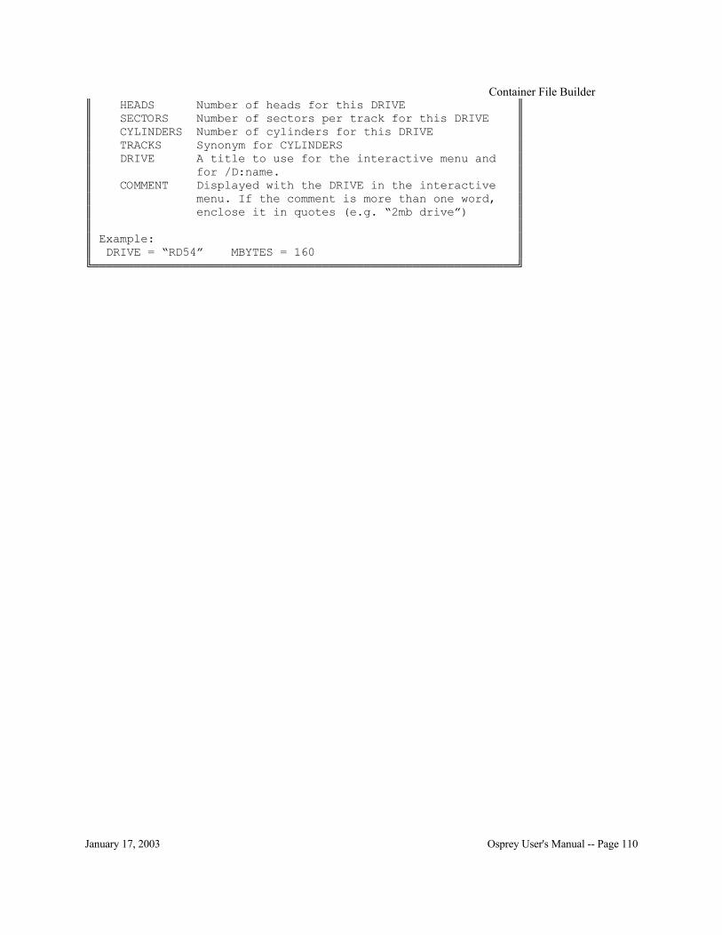
Container File Builder
January 17, 2003 Osprey User's Manual -- Page 110
║ HEADS Number of heads for this DRIVE ║ ║ SECTORS Number of sectors per track for this DRIVE ║ ║ CYLINDERS Number of cylinders for this DRIVE ║ ║ TRACKS Synonym for CYLINDERS ║ ║ DRIVE A title to use for the interactive menu and ║ ║ for /D:name. ║ ║ COMMENT Displayed with the DRIVE in the interactive ║ ║ menu. If the comment is more than one word, ║ ║ enclose it in quotes (e.g. “2mb drive”) ║ ║ ║ ║ Example: ║ ║ DRIVE = “RD54” MBYTES = 160 ║ ╚═════════════════════════════════════════════════════════════╝

Container File Builder
January 17, 2003 Osprey User's Manual -- Page 111


Filetape
January 17, 2003 Osprey User's Manual -- Page 113
FILETAPE Filetape is used to emulate a tape drive using DOS files. See the configuration section on page 85 to
install filetape. Filetape is a convenient way to dump data from one system and move it to another system, since
DOS files are so easily portable in a number of different ways.
Filetape Control Menu(NT)
The filetape menu is available from the toolbar under Devices. Filetape Control Menu(DOS)
The filetape control menu can be activated while the Osprey is executing by striking Alt-F. The Osprey is suspended at that point, and the filetape control menu is displayed. A reverse video bar shows the current option. Select a new option by using the arrow keys to move the bar, or typing
the option number, then striking the return key. 0 -- Continue 1 -- Close File 2 -- Rewind Tape 3 -- Open New File 4 -- Toggle Write Protect
In addition to the filetape control menu, some other information is displayed.
Tape Filename: a filename Current Object: the object number. 0 indicates fully rewound. User Protect: {On Off} File Protect: {On Off} Status Message: the last status message
Option 0 -- Continue Resume the Osprey at the exact point that the inner control menu was invoked.
Option 1 -- Close File This is the same as dismounting a physical tape. The files may be copied or deleted after the files
are closed.

Filetape
January 17, 2003 Osprey User's Manual -- Page 114
Option 2 -- Rewind Tape The current filetape object number is reset to the beginning of the tape.
Option 3 -- Open New File This is the same as mounting a new physical tape. The new files are reserved for use with the
Osprey system until they are closed or the Osprey is exited.
Option 4 -- Toggle Write Protect The state of the user write protect is switched between ON and OFF. Note that the files might still
be write protected independently of the user write protect.

Filetape
January 17, 2003 Osprey User's Manual -- Page 115


Keyname
January 17, 2003 Osprey User's Manual -- Page 117
KEYNAMEDOS Keyname is used to display the names of the keys on the PC keyboard. The names are used in the
NumLockKey configuration as well as the VT100 configuration. Start the Keyname program from the Osprey directory. Each key you touch will display its name.
Use Ctrl-Break to terminate the program. E.g.:
C:\OSPREY> keyname Please touch a key: Touch the Enter key You may use 0x000D or CR for that key Please touch a key: Touch the F1 function key You may use 0x013B or F1 for that key Please touch a key: Touch the 0/Ins key on the keypad You may use 0x0252 or KPDZERO for that key Please touch a key: Touch Ctrl-Break ^C C:\OSPREY>

Keyname
January 17, 2003 Osprey User's Manual -- Page 118
KEYNAMENT
Keyname is used to display the names of the keys on the PC keyboard. The names are used in the VT100 configuration.
Start the Keyname program by clicking Start \ Program Files \ Get Key Mappings. The program will announce itself and the Osprey version it reports on.
E.g.: Start the program, then touch Enter , followed by F1, and then the 0/Ins key on the keypad.

VT100.CNF
January 17, 2003 Osprey User's Manual -- Page 119
VT100.CNF Certain strings may contain characters that are not allowed in our normal Osprey configuration file, like the semicolon. You must enclose the entire string in quotation marks if it contains a semicolon
or quotation mark. It is not necessary to use a quoted string for J11File = and related lines (see page 1). Please see the details of quoted strings on page 29.
Note: If you feel that the VT100 emulation is not working when you use function keys or arrows, please add /RxDelay:1000 /TxDelay:1000 (on page 43) to your Con = line. Many operating
systems can not handle extremely high baud rate VT100 devices (as our Con = is). If the console becomes unusable, because an application has sent peculiar escape codes for example, the screen can be reset. (NT)Click the upper left corner (system control) of the window and selecting
Reset. (DOS)Press Alt-R to reset the screen. The VT100 configuration file VT100.CNF is an ASCII file defining what VT100 codes are sent for
PC keys and other characteristics of the VT100 emulator. The file must reside in the current directory, or a directory listed in the OSPREY environment variable or in the PATH. The Osprey
searches for all files in that order. The VT240.CNF, if used, must be renamed to VT100.CNF before the Osprey will use it. You should preserve the original VT100.CNF in case the
VT240.CNF does not fit your needs. Note that the VT240.CNF simply changes the behavior of the keyboard. It does not add extra VT240 emulation.
Blank lines and comments in the configuration file are ignored. A comment is defined as anything which follows a semicolon (;). Upper case and lower case are treated equally, except when
contained within quotation marks. Tabs and spaces are treated equally, except when contained within quotation marks. At least one space or tab must separate each option or specifier from other
options and specifiers. Each line in the configuration file contains a single definition.
All codes are octal unless otherwise specified. However, the codes may also be given in hexadecimal or decimal. Hexadecimal codes must be preceded by 0x (0x41) and decimal codes
must be followed by . (65.). Octal codes may also be preceded by 0 (0101) in case a code does not default to octal.
Several helper files may be copied and pasted into VT100.CNF for certain applications. Some applications require keyboard parity or only upper case. In those cases, insert one of the following
files into your VT100.CNF or add the line Include VTUCASE.CNF File Usage VTUCASE.CNF Upper case letters VTPARE.CNF Mixed case letters and even parity VTPARO.CNF Mixed case letters and odd parity VTPAREU.CNF Upper case letters and even parity VTPAROU.CNF Upper case letters and odd parity

VT100.CNF
January 17, 2003 Osprey User's Manual -- Page 120
Configuration Commands 52Key <code> = Remaps the VT52 mode keyboard. For PC key names and values, see the keyname program on page 117. 52Key F1 = 0x1B 0x50
{<VT100 octal code(s)> <”string”>}
52AKey <code> = Remaps the VT52 mode keyboard in application keypad mode. For PC key names and values, see the keyname program on page 117. 52AKey KPDZERO = 0x1B 0x3F 0x70
{<VT100 octal code(s)> <”string”>}
Key <code> = Remaps the standard mode VT100 keyboard. For PC key names and values, see the keyname program on page 117. Key F1 = 0x1B 0x4F 0x50
{<VT100 octal code(s)> <”string”>}
AKey <code> = Remaps the alternate keypad mode VT100 keyboard. For PC key names and values see the keyname program on page 117. AKey KPDZERO = 0x1B 0x4F 0x70
{<VT100 octal code(s)> <”string”>}
Char <code> = Remaps the standard VT100 display characters. Char 0101 = 0102 ;All A’s show as B’s
<octal code>
Color <VT100 attribute> =(DOS)
Changes a attribute / color mapping. See page 122 for a description of the attributes. Color Underline = Bright Red
<PC attribute>
Graphic <code> = Remaps the graphics mode VT100 display characters. Graphic 0141 = 0xDB ;Checkerboard
<octal code>
80ColumnMode =(DOS)
The default is 3. <decimal code>

VT100.CNF
January 17, 2003 Osprey User's Manual -- Page 121
Changes the PC video mode used to support the VT100 80-column mode. For video modes, see the documentation for SCRMODE beginning on page 125. 80ColumnMode = 2 132ColumnMode =(DOS)
The default is 0x55. Changes the PC video mode used to support the VT100 132-column mode. For video modes, see the documentation for SCRMODE beginning on page 125. 80ColumnMode = 0x57
<decimal code>
IDString = The default is “\033[?1;0c” Specifies the I.D. String returned when the VT100 is queried with ESC [ c or ESC Z in VT100 mode. IDString = “c”
{<I.D. codes> “string”}
Type = The default is VT100. Specifies the default start up mode for the emulation. Many programs will send codes to the VT100 that will override this mode. Type = GENRAD
{VT100 VT52 GENRAD}
Special Configuration Considerations (NT)NUMLOCK is a valid key name and may be mapped just like any other key.
E.g. NumLock = 0x1B 0x4F 0x50 ;Make NumLock behave like PF1
(DOS)The VT100 emulator can not map the NumLock key directly, but the Osprey can. Therefore, first switch the NumLock key with another key (see NumLockKey on page 35) and then map the
other key using VT100.CNF. The following example will end up with the PC F12 key toggling the NumLock light, and the PC NumLock key behaving as the VT100 PF1 key.
OSPREY.CNF NumLockKey = F12 ;Use F12 as the NumLock key and NumLock as the F12 key
VT100.CNF Key F12 = 0x1B 0x4F 0x50 ;Use F12 for PF1

VT100.CNF
January 17, 2003 Osprey User's Manual -- Page 122
(DOS)Color and Attributes The attributes (either VT100 or PC) are just lists of words separated by spaces. You may also
separate the words with either + or & if you feel that would make the configuration file easier to understand (e.g. Color Underscore+Blink = Green).
(DOS)VT100 Attributes
These four VT100 attributes may be combined into a total of sixteen different attribute possibilities. Preferred name Synonyms Highlight Intense, H Underscore Underline, U Reverse ReverseVideo, R Blink Blinking, B
(DOS)PC Attributes The PC attributes are given as a foreground color and a background color. This may be done in one
of three ways.
1) Just type a color or combination of colors. This will set the foreground color only.
Blue
2) Type the foreground color(s) then ON then the background colors.
Blue ON Red
3) Type Foreground, then the foreground color(s), then Background followed by the background color(s). The Foreground and Background may be in either order.
Foreground Bright White Background Blue
Preferred name Synonyms
Normal Bright Highlight, Intense, Bri Underscore Underline
Reverse Blink Blinking, Bli Gray Grey Black Blue Green Cyan LightBlue, LtBlue

VT100.CNF
January 17, 2003 Osprey User's Manual -- Page 123
Red Magenta Purple Yellow Brown, Orange
White Bright Black Gray Bright Red Pink

VT100.CNF
January 17, 2003 Osprey User's Manual -- Page 124

SCRMODE
January 17, 2003 Osprey User's Manual -- Page 125
SCRMODE(DOS) SCRMODE is used to determine which video modes must be used for the VT100 emulation when
selecting 80 column or 132 column modes.
Results Log File SCRMODE will generate a log file called SCRMODE.LOG. If the environment variable
LOGIN_NAME is set, SCRMODE will use the value of LOGIN_NAME as a base filename, then append .LOG. Novell networks set LOGIN_NAME automatically. In any case, SCRMODE tells
you what log file it created. The log file will look something like this:
Mode 2 0x02 80-column. Grade: A Mode 3 0x03 80-column. Grade: A Mode 7 0x07 80-column. Grade: B Mode 85 0x55 132-column. Grade: A Mode 87 0x57 132-column. Grade: B The grade simply represents whether the text mode uses B800:0 or B000:0 or A000:0 for its video
memory. You should use the grade-A modes if they are available.
Video Controller Lock Up Problems There are rare machines that will lock up when certain video modes are set. If this happens, you
need to exclude testing those video modes by using the /N:mode switch. To determine which modes lock up the machine, follow these directions.
First, start SCRMODE /A. When the machine locks up, reboot and examine SCRMODE.LOG. The file will look something like this:
Mode 0 0x00 Rows:25 Columns: 40 Text:B800:0000 Mode 1 0x01 Rows:25 Columns: 40 Text:B800:0000 Mode 2 0x02 Rows:25 Columns: 80 Text:B800:0000 Notice that mode 2 is the last mode that got logged. That means that the next mode, mode 3, must have locked up the machine. Now, start again with the /N:mode switch for this mode. You would type SCRMODE /A /N:3. If SCRMODE locks up again, look at the file and add the next mode that locks up the machine. Mode 0 0x00 Rows:25 Columns: 40 Text:B800:0000 Mode 1 0x01 Rows:25 Columns: 40 Text:B800:0000 Mode 2 0x02 Rows:25 Columns: 80 Text:B800:0000

SCRMODE
January 17, 2003 Osprey User's Manual -- Page 126
Mode 4 0x04 Rows:25 Columns: 40 Graphics Mode 5 0x05 Rows:25 Columns: 40 Graphics Mode 6 0x06 Rows:25 Columns: 80 Graphics Here, you would type SCRMODE /A /N:3 /N:7. Keep going until you have all the /N:modes which lock up your machine. Then, re-run SCRMODE without the /A, but with all the /N:modes.
Using New Video Modes To specify which video modes should be used for the VT100 emulation, modify these two lines in
the VT100.CNF file: 80ColumnMode = 0x03 132ColumnMode = 0x55
Complete List of Modes SCRMODE can also be used to determine what all the video modes do. If you start SCRMODE
with /A, it creates a more detailed log file. Mode 0 0x00 Rows:25 Columns: 40 Text:B800:0000 Mode 1 0x01 Rows:25 Columns: 40 Text:B800:0000 Mode 2 0x02 Rows:25 Columns: 80 Text:B800:0000 Mode 3 0x03 Rows:25 Columns: 80 Text:B800:0000 Mode 4 0x04 Rows:25 Columns: 40 Graphics Mode 5 0x05 Rows:25 Columns: 40 Graphics Mode 6 0x06 Rows:25 Columns: 80 Graphics Mode 7 0x07 Rows:25 Columns: 80 Text:B000:0000 Mode 8 0x08 Rows:25 Columns: 80 Graphics Mode 9 0x09 Unsupported
etc.
Help Screen A brief help screen is available when you start SCRMODE with the /H switch.
╔═════════════════════════════════════════════════════════════╗
║ SCRMODE Rev 2.00 ║ ╟─────────────────────────────────────────────────────────────╢
║ General form: SCRMODE [args] [files] ║
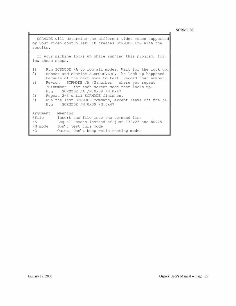
SCRMODE
January 17, 2003 Osprey User's Manual -- Page 127
╟─────────────────────────────────────────────────────────────╢ ║ SCRMODE will determine the different video modes supported║ ║ by your video controller. It creates SCRMODE.LOG with the ║ ║ results. ║ ╟─────────────────────────────────────────────────────────────╢ ║ If your machine locks up while running this program, fol- ║ ║ low these steps. ║ ║ ║ ║ 1) Run SCRMODE /A to log all modes. Wait for the lock up.║ ║ 2) Reboot and examine SCRMODE.LOG. The lock up happened ║ ║ because of the next mode to test. Record that number. ║ ║ 3) Re-run SCRMODE /A /N:number where you repeat ║ ║ /N:number for each screen mode that locks up. ║ ║ E.g. SCRMODE /A /N:0x09 /N:0x47 ║ ║ 4) Repeat 2-3 until SCRMODE finishes. ║ ║ 5) Run the last SCRMODE command, except leave off the /A.║ ║ E.g. SCRMODE /N:0x09 /N:0x47 ║ ╟─────────────────────────────────────────────────────────────╢ ║ Argument Meaning ║ ║ @file Insert the file into the command line ║ ║ /A Log all modes instead of just 132x25 and 80x25 ║ ║ /N:mode Don’t test this mode ║ ║ /Q Quiet. Don’t beep while testing modes ║ ╚═════════════════════════════════════════════════════════════╝

SCRMODE
January 17, 2003 Osprey User's Manual -- Page 128

GETDISK
January 17, 2003 Osprey User's Manual -- Page 129
GETDISK
Disk to DOS Container File Copy The Getdisk utility copies from existing disks on the Unibus or Qbus into container files. You must have the external bus hooked up and powered on before you can use Getdisk. You must also ensure that the NPR chain is intact. A similar utility, Putdisk, copies from a container file onto the Unibus or Qbus. This will destroy all data on the target Unibus or Qbus disk. The command interface
is very similar. The Getdisk utility supports both the Unibus (GETDISKU) and the Qbus (GETDISKQ). The
program behaves identically in either case. (DOS)To start Getdisk, simply type either GETDISKU or GETDISKQ from the DOS prompt. The batch
file starts Osprey with GETDISKU.CNF or GETDISKQ.CNF. To quit Getdisk, choose menu option 2.
(NT)To start Getdisk, click Start \ Programs \ Osprey \ Qbus Getdisk or Start \ Programs \ Osprey \ Unibus Getdisk.
Use the ESC key in GETDISK to back up by one menu at a time. When the program starts, it will test for several controllers and units. The status of the auto-detect sequence is displayed, and then the initial menu will be presented. The most common one or two
addresses for each controller type will be automatically scanned for controllers. If your controller is not at one of the default addresses, you will have to specify the parameters to the Getdisk program.
See below for that information. If you are unsure of which addresses are in use, you can run SCANIO from the DOS prompt to get a list of addresses.
The following example shows a typical installation with a single MSCP drive with a I/O base of 172150.
Osprey Get Disk Program Rev 7.13 August 30, 1996 Copyright © 1996 Strobe Data, Inc. ALL RIGHTS RESERVED.
Type ESC to continue ... DU controller not found at 172154 (vct:150) RH controller not found at 176700 (vct:254) RH controller not found at 172040 (vct:204) DK controller not found at 177400 (vct:220) DM controller not found at 177440 (vct:210) DL controller not found at 174400 (vct:160) DX controller not found at 177170 (vct:264) DX controller not found at 177200 (vct:270)
Device controllers detected: *0.. DUA ! Ready Vct:154 Adr:172150 Ints: 9

GETDISK
January 17, 2003 Osprey User's Manual -- Page 130
The main menu will look something like this.
PDP-11 Get Disk 1.. Help 3.. Get disk 5.. Delete device 7.. Show devices 2.. Exit 4.. Add device 6.. Change device 8.. Show units
Enter option ................... [3.] When you choose option 3, the dialogue for actually copying the disk begins. Answer Y verify the copy, or N to just copy without verifying. Verification, the default, is highly recommended. The program will next prompt for the DOS container filename. Specify the full drive and path. If the file does not exist, you will be prompted to create it. If the file does exist, you will be prompted to reuse it. You may provide a filename with wildcards if you want to reuse an existing file. Getdisk
will prompt you for each file that matches in sequence. The current block count, total block count, and block size is displayed while the program is copying
and then verifying. For non-MSCP disks, the cylinder, track, and sector disk address is also displayed.
If your disk controller is not located in the I/O page at one of the addresses searched by Getdisk, you must specify where the controller is based. Choose option 4 to add a device. The add device
function will prompt you for the device class, the vector address, and the device address. If you don’t know the device class number, touch the ? key and Getdisk will display the valid choices. The DISKCOPY sources are provided in the cross assembler. See page 131 for more details.

DOSLink and SFX
January 17, 2003 Osprey User's Manual -- Page 131
DOSLink and Strobe File Exchange There are two distinct methods to transfer data between a container file (or floppy) and the DOS/NT
file system. Your container file or floppy must be formatted for RSX or RSTS or RT-11 in order to use these
utilities. If you want to transfer files while running your PDP-11 operating system, you must use one of the
DOSLink utilities. Directions for those utilities are included in each installation package. If you want to transfer files while running DOS, you must use the Strobe File Exchange (SFX)
program. Directions for that utility are included in the installation package. Do not use SFX on a container file that is currently being used by an Osprey. If you do, you
may corrupt or lose all your data. It is safe to use the DOSLink programs from the Osprey. Utility name FTP address DOSLINK/RSX ftp://ftp.strobedata.com/pub/osprey/rsxcopy.exe DOSLINK/RSTS ftp://ftp.strobedata.com/pub/osprey/rstscopy.exe DOSLINK/RT-11 ftp://ftp.strobedata.com/pub/osprey/rt11copy.exe Strobe File Exchange ftp://ftp.strobedata.com/pub/osprey/*
*The actual filename has a version number appended to it. Look for SFXnnn.EXE.

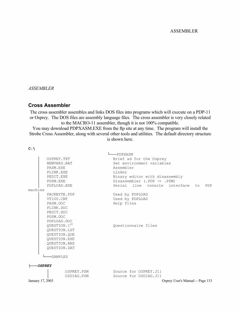
ASSEMBLER
January 17, 2003 Osprey User's Manual -- Page 133
ASSEMBLER
Cross Assembler The cross assembler assembles and links DOS files into programs which will execute on a PDP-11 or Osprey. The DOS files are assembly language files. The cross assembler is very closely related
to the MACRO-11 assembler, though it is not 100% compatible. You may download PDPXASM.EXE from the ftp site at any time. The program will install the
Strobe Cross Assembler, along with several other tools and utilities. The default directory structure is shown here.
C:\ └───PDPXASM
│ OSPREY.TXT Brief ad for the Osprey │ NEWVARS.BAT Set environment variables │ PASM.EXE Assembler │ PLINK.EXE Linker │ PEDIT.EXE Binary editor with disassembly │ PDSM.EXE Disassembler (.PDP -> .PSM) │ PDPLOAD.EXE Serial line console interface to PDP machine │ PACKBYTE.PDP Used by PDPLOAD │ VT100.CNF Used by PDPLOAD │ PASM.DOC Help files │ PLINK.DOC │ PEDIT.DOC │ PDSM.DOC │ PDPLOAD.DOC │ QUESTION.1ST Questionnaire files │ QUESTION.LST │ QUESTION.QUE │ QUESTION.EXE │ QUESTION.ANS │ QUESTION.DAT │
└───SAMPLES
├───OSPREY │ OSPREY.PSM Source for OSPREY.J11 │ OSDIAG.PSM Source for OSDIAG.J11

ASSEMBLER
January 17, 2003 Osprey User's Manual -- Page 134
│ DISKCOPY.PSM Source for DISKCOPY.PDP │ DEQNAROM.PSM Source for DEQNAROM.PDP │ TESTDISK.PSM Source for TESTDISK.DU0 │ XHBOOT.PSM Source for XHBOOT.ROM │ TM11COPY.PSM Source for TM11COPY.PDP │
├───INC │ ... Library include files └───LIB
... Library source files
To modify the default OSPREY.J11, follow these steps. 1) Edit the source file (C:\PDPXASM\OSPREY\OSPREY.PSM). 2) Assemble the file: pasm osprey 3) Link the file: plink osprey 4) Include the new version in your configuration file:
J11File = C:\PDPXASM\OSPREY\OSPREY.PDP Strobe Data is not responsible for the accuracy of the source files provided, nor any changes. No warranty is made for the usefulness, reliability, or safety of the programs provided or generated.

ASSEMBLER
January 17, 2003 Osprey User's Manual -- Page 135


Appendix A
January 17, 2003 Osprey User's Manual -- Page 137
APPENDIX A LSRMST definition(NT)
LSRMST (Line Status / Modem Status) codes are used in CharPipe = (see page 59) when the /LSRMST:value option is given. The LSRMST protocol provides escape codes to represent actual
line status (e.g. break detected) and modem status (e.g. CTS) changes. This protocol has been extended to support sending line control (e.g., select parity), modem control (e.g, set RTS) and baud
rate sequences from the attached virtual device to the customer end of the named pipe. Without /LSRMST:value, all virtual device line control and modem control changes are ignored,
and line status and modem status changes cannot be written to the customer end of the named pipe. CharPipe passes data through without inspection or modification.
When LSRMST mode is active (i.e., when /LSRMST:value is present and value is non-zero), line status, modem status, line control, modem control and baud rate commands are prefixed by the byte
given in value (the LSRMST escape code). Following this byte is the LSRMST command sequence.
The bit values for line status, modem status, line control and modem control used by LSRMST are compatible with the 8250/16450/16550 serial line controller chips used by the PC, XT, and AT
compatible machines. In the following discussion, data transmission is described from the point of view of the customer
end of the named pipe. Generally, status changes are written to the customer end of the named pipe and control commands are read from the customer end of the named pipe.
LSRMST commands Following the LSRMST escape code is a single command byte and possibly one or more data bytes.
If the customer sends an escape code followed by an unknown command byte, CharPipe will discard the LSRMST escape code and transmit the unknown command byte to the attached virtual
device. In the following descriptions, 0x?? is used to represent the LSRMST escape byte (value above).
Command byte Meaning 0x00 Escape. An LSRMST escape code should be inserted into the data stream. 0x01 Data and status. Written to the customer end of the named pipe: the first
following data character contains the line status register, and the second data character contains the received data byte associated with the line status. This sequence will never be read at the customer end of the named pipe.
0x02 Status only. Written to the customer end of the named pipe: the data character contains the line status register. Read at the customer end of the named pipe: the data character contains the line control register.

Appendix A
January 17, 2003 Osprey User's Manual -- Page 138
0x03 Modem status. Written to the customer end of the named pipe: the data character contains the modem status register. Read at the customer end of the named pipe: the data character contains the modem control register.
0x05 Baud rate. Read at the customer end of the named pipe: the first data character contains the least significant byte of the baud rate divisor, and the second data character contains the most significant byte of the baud rate divisor. This LSRMST command is not part of the standard as defined by Microsoft, and was created for Strobe Data use with the CharPipe. If written to the customer end of the named pipe, this command is ignored by CharPipe.
Line Status Register The line status register (LSR) follows command bytes 0x01 and 0x02 when written to the customer
end of the named pipe. Bit Meaning 0x10 Break detected 0x08 Framing error detected 0x04 Parity error detected 0x02 Overrun error detected
Written to the customer end of the named pipe: 0x?? 0x01 LSR data 0x?? 0x02 LSR
Line Control Register The line control register (LCR) follows command byte 0x02 when read at the customer end of the
named pipe. Bit Meaning 0x40 Break state to set 0x20 Stick parity 0x10 Even parity select 0x08 Parity enable 0x04 Stop bits (0=1 stop bit, 1=2 stop bits (1.5 if 5 bits per word)) 0x02 Bits per character, with 0x01. (00=5 01=6 10=7 11=8) 0x01 See 0x02
Read at the customer end of the named pipe: 0x?? 0x02 LCR

Appendix A
January 17, 2003 Osprey User's Manual -- Page 139
Modem Status Register The modem status register (MSR) follows command byte 0x03 when written to the customer end of
the named pipe. Bit Meaning 0x80 Carrier detect 0x40 Ring indicator 0x02 CTS has changed state 0x01 DSR has changed state
Written to the customer end of the named pipe: 0x?? 0x03 MSR
Modem Control Register The modem control register (MCR) follows command byte 0x03 when read at the customer end of
the named pipe. Bit Meaning 0x02 RTS state to set 0x01 DTR state to set
Read at the customer end of the named pipe: 0x?? 0x03 MCR
Baud Rate
The baud rate bytes follow command byte 0x05 when read at the customer end of the named pipe. The baud rate divisor can be calculated by dividing the crystal rate input to a typical COM (8250)
chip by both the crystal rate and the baud rate. For the CharPipe implementation, the baud rate divisor is 115,200 divided by the baud rate and truncated to the nearest lower integer. This divisor
matches the divisor programmed into the divisor latch register of the 8250 class chips. The low order eight bits (LSB) of the divisor are transmitted first, followed by the high order eight
bits (MSB). Divisor Bytes
Baud LSB MSB 300 0x80 0x01 1200 0x60 0x00 2400 0x30 0x00 4800 0x18 0x00 9600 0x0C 0x00
Read at the customer end of the named pipe: 0x?? 0x05 LSB MSB


Appendix B
January 17, 2003 Osprey User's Manual -- Page 141
APPENDIX B CPU Loading
The host CPU is responsible for processing all virtualized I/O. A small number of systems that perform a large amount of virtualized I/O have a severe impact on the host CPU. If a particular
system is found to have a large impact on the host CPU, there are some things that can be done to reduce that load.
Serial Lines and Transmit Buffers using COM = Serial lines on the Osprey system are implemented using a double-buffered scheme to improve
performance. The virtual I/O handler (e.g. = CONSOLE) has a buffer specified by /TxBuff:n on the right hand side of the equals sign. The physical I/O handler (e.g. COM =) has a buffer specified by
/TxBuff:n on the left hand side of the equals sign. To reduce host CPU loading, the right hand side /TxBuff:n must be two or more greater than the left
hand side. Additionally, the larger the host side buffer, the more the CPU loading is reduced. Some systems do not respond well when large buffers are present. The /TxBuff:n parameter can be
adjusted to suit systems tolerant of large buffers or intolerant of large buffers. Examples:
COM /Port:1 /TxBuff:20 = CONSOLE /TxBuff:22 ;Low CPU loading
COM /Port:1 /TxBuff:1 = CONSOLE /TxBuff:3 ;Higher CPU loading
COM /Port:1 /TxBuff:1 = CONSOLE /TxBuff:2 ;Very high CPU loading Serial Lines and TxDelay using COM =
These calculations for reducing CPU loading should only be used in systems known to have extreme host CPU loading. Except in extreme cases, the standard calculation for /TxDelay on page
43 may be used. Some systems require the use of /TxDelay:n to reduce the effective baud rate while the buffers are
being filled. If the /TxDelay:n specified is longer than one character time, the host CPU will be loaded much more than if /TxDelay:n is shorter than one character time.
It’s a little complicated to determine whether or not the /TxDelay:n is actually shorter or longer than one character time. The delay given is rounded up to the next time quantum, which varies
depending on which Osprey product is running and what speed it is running. Determine if your board is an Osprey/PCI, Osprey/ISA or OSPREY/DCJ11 to calculate the time quantum. The Osprey/DCJ11 has a large 3”x1.5” CPU on it. The gold fingers and the bus they plug into distinguish the other two boards.
If your board is an Osprey/DCJ11: Find the J11 crystal rate. Run the Osprey/NT system and click Windows \ Initialization
messages. Scroll down to find the J11 Crystal.

Appendix B
January 17, 2003 Osprey User's Manual -- Page 142
Divide 3744 by the J11 crystal rate shown. If the number is 18.0 Mhz, use 18 and not 18,000,000. The answer is the time quantum. The time quantum should be between 200 and 300.
If your board is an Osprey/ISA, the time quantum is 250.
If your board is an Osprey/PCI: Find the firmware version of the Osprey/PCI. Run the Osprey/NT system and click
Windows \ Initialization messages. Scroll down to Firmware Rev. Find the X86 crystal rate. Run the Osprey/NT system and click Windows \ Initialization
messages. Scroll down to X86 Crystal. If the firmware is 1, 2 or 3, divide 8250 by the X86 crystal rate shown. If the number is 36.0
Mhz, use 36 and not 36,000,000. The answer is the time quantum. The time quantum should be between 200 and 300.
If the firmware is 4 or more, divide 8192 by the X86 crystal rate shown. If the number is 36.0 Mhz, use 36 and not 36,000,000. The answer is the time quantum. The time quantum should be between 200 and 300.
Find the effective /TxDelay:n.
Multiply the time quantum by 1, 2, 3, etc. until the product is equal to, or larger than, the /TxDelay:n found in the configuration file. The product is the effective /TxDelay:n.
Find the number of character bits.
Examine /Mode:baud,parity,data bits,stop bits. Add 1 to the number of data bits. Add the number of stop bits. Add 1 if the parity isn’t None. The answer is the number of character bits. If /Mode is missing, you will need to examine the Port properties in the Windows Control Panel.
Find the length of one character time.
Divide 1,000,000 by the baud rate and multiply by the number of character bits.
Find the low CPU load /TxDelay:n. Multiply the time quantum by 1, 2, 3, etc. until the product is larger than the length of one
character time. Subtract one time quantum from the product. Subtract two from the difference. The new answer is the low CPU load /TxDelay:n.
If the calculated effective /TxDelay:n is longer then the low CPU load /TxDelay:n, the host CPU
will be loaded more heavily. To reduce CPU loading, use the low CPU load /TxDelay:n. Examples:
COM /Port:1 = CONSOLE /TxDelay:1042 /Mode:9600,E,8,2
An Osprey/QXP rev 4 running the default speed has an X86 crystal of 36Mhz. Dividing 8192 by 36 give 227.6 as the time Quantum.
227.6 times 4 is only 910, so 227.6 times 5 (or 1,138) is the effective /TxDelay. The number of character bits is 1+8+2+1 or 12. 1,000,000 / 9600 * 12 gives 1250 for the character time.

Appendix B
January 17, 2003 Osprey User's Manual -- Page 143
227.6 times 6 (1,365.6) is the first product larger than 1250. Subtractimg the time quantum and an additional 2 gives 1136 for the low CPU load TxDelay.
The calculated effective /TxDelay is 1,138. This is less than the character time 1250 so the host
CPU already has a low load.
COM /Port:1 = CONSOLE /TxDelay:1042 /Mode:9600,N,8,1
An Osprey/QXP rev 4 running the default speed has an X86 crystal of 36Mhz. Dividing 8000 by 36 give 227.6 as the time Quantum.
227.6 times 4 is only 910, so 227.6 times 5 (or 1,138) is the effective /TxDelay. The number of character bits is 1+8+1+0 or 10. 1,000,000 / 9600 * 10 gives 1042 for the character time. 227.6 times 5 (1,138) is the first product larger than 1042. Subtractimg the time quantum
and an additional 2 gives 908 for the low CPU load TxDelay.
The calculated effective /TxDelay is 1,138. This is larger than the character time 1042 so the host CPU will be loaded more heavily. Reduce to /TxDelay:908 for lower host CPU loading.


Index
January 17, 2003 Osprey User's Manual -- Page 145
INDEX

Index
January 17, 2003 Osprey User's Manual -- Page 146
INDEX
/
/Adr: 48 /CD: 51 /CTS: 51 /DSR: 51 /DTR: 51 /Mode: 51 /Pri: 48 /RI: 52 /RTS: 51 /RXBuff: 50 /RXDelay: 50 /Slot: 49 /TXBuff: 50 /TXDelay: 50, 77 /UnitName: 52, 53, 54, 55, 56,
57, 71, 74, 96, 98, 99 /Vct: 48
1
11/23 43 11/70 82 11/73 86 11/83 86 11/93 86 160010 78, 79 160020 75, 76 160440 76, 77 164100 92 165000 83, 84, 85, 86 170000 97 170200 85, 87 170400 81 170420 82 172100 83, 86 172150 59 172440 100, 101 172520 99, 100, 102, 103, 104,
105 172540 81 173000 83, 84, 85, 86 174400 62, 63 174440 95 174500 102 176460 83 176470 88 176500 65, 77, 78 176700 61 177170 58, 64, 65 177400 61 177440 62
177460 60 177514 79 177520 82, 83, 84, 85, 86, 87 177522 84, 87 177524 82, 84, 85, 87 177526 84, 87 177546 82, 85 177560 75 177570 82, 84, 85, 87 177740 86 177744 82, 85 177760 84, 87 177770 86 1777720 80 177774 87
3
3C509 12, 13
5
52AKey 134 52Key 134
A
Abort 113 AC power level 36 Alt-C 35, 113 AltKeyMode 35 ASPI 14, 15, 52, 97, 99
tape 97, 99 ASPIDisk 52 ASPITape 97
ASSEMBLER 149 AT-GPIB-TNT 47, 91
B
Background 136 Base address 16 baud 50, 51, 153, 155 BB1004 65 BB1008 66 BB2016 67 BDV11 84, 87 BinFile 36 Blink 136 BLOCK
physical devices 52
Virtual Devices 58 Block Devices 46 BMP 43 BoardName 36 Boca 66 Boot 113 break 75 BusTimeout 36
C
cache disk caching 21
CacheSize 36 CALENDAR 81
Physical Devices 81 Virtual Devices 81
Calendar Devices 46 carrier detect 51 CHAR
Physical Devices 65 Virtual Devices 75
Character Devices 46 Character Options 50 charpipe 68 CldFile 36, 37 clear to send 51 CLOCK 81
Physical Devices 81 Virtual Devices 81
Clock Devices 47 Cluster 52 CMOS setup 21 color 136 Color 134 COM 68 Command line 33 CON 70 Configuration
calendar devices 46 character devices 46 clock devices 47 CPU devices 47 disks 46 DOS devices 47, 48, 88, 89,
90, 91 GPIB devices 47 net devices 47 ODT devices 47 PROM devices 47 tape devices 47
Configuration file 33 Console
switch 71 CONSOLE 46, 75

Index
January 17, 2003 Osprey User's Manual -- Page 147
Container file builder 121
CONTAINR 15, 16, 121, 122, 123
Copy customer data 15
Core dump 113 CPU 82
Physical Devices 82 Virtual Devices 82
CPU Devices 47 CS11 75, 76
D
data set ready 51 DC power level 36 DECnet 93, 94 delay
character 50, 77 DEQNA 95 disk 49, 59 MSCP 60
DEQNA 12, 13, 47, 93, 94, 95 Device Configuration 46 DH11 46, 76 DHU11 46, 76 DHV11 46, 77 diagnostic
hard disk 22 hwdiag 14 Osprey 29 PC 22
DIGI 71 Digiboard 71 Disk caching 21 disk errors 49 Disk image 15 DLV11 46, 66, 67, 68, 71, 74,
77, 78 DOS
Physical Devices 88 Virtual Devices 88
DOS Devices 47, 48, 88, 89, 90, 91
DOSDevice 47, 48, 88 DOSDEVICE 88, 97 DOSLINK 88, 147 Drive Options 49 DTR 51, 66, 75, 96 DZ11 46, 78 DZQ11 46, 78 DZV11 46, 79
E
EditCommand 37
EEPFile 37 EEPROM 37, 82, 83, 85 EMS 53 EnableBusResetMenu 37 environment variables 33, 122,
149 Example
configuration file 35 Exit 113
F
FCC 9 File 54 FileTape 98, 127 FIXWATCH/FIXSTAT 22 FlatPROM 47, 97 Floppy 55 font 11 Foreground 136 FSETUP 21 FTESTPC 22 FTP 13 FW11 46, 58 FWAFile 37 FWV11 46, 58
G
GCACycles 38 General Specifiers 35 GETDISK 1, 15, 16, 143 GPIB 47, 91, 92
Physical Devices 91 Virtual Devices 92
GPIB Devices 47
H
Halt 38 Hardware conflicts 16 Highlight 136 Home Page 13 HSC50 59 HWDIAG 14, 15
I
IEEE 91, 92 GPIB 92
IEQ11 47, 91, 92 IEU11 47, 92 Installation 9
Software 11 Instance Options 48 Intense 136
interleaved 63 Internet 12, 13 Interrupt 38 IOAddress 38 IOTFile 38 IRQ 38
table 16
J
J11Crystal 39 J11File 40
K
KB11-C 47, 82 KDJ-11 84, 86 KDJ11-E 29, 32, 35, 42, 45, 47,
82, 84, 85, 86, 87 KESTREL.X86 45
KEYNAME 131 KW11P 47, 81 KW11-P 81 KWV11-C 82 KWV11-CAL 46, 81
L
line frequency 83 LogBuffers 40 LogFile 40 logo 33 LP11 46, 79 LPT 72 LPV11 46, 73, 79 LSRMST 68, 153, 157
M
MaxWHOALoops 40 MEM 56 MemorySize 40 modem signals 51 MSCP 16, 29, 30, 32, 33, 46, 52,
53, 54, 55, 56, 57, 59, 143 MSV05 48, 99 MSV05B 48, 100
N
NA509 47, 93, 94 named pipe 68 NET
physical devices 92 Virtual Devices 95

Index
January 17, 2003 Osprey User's Manual -- Page 148
Net Devices 47 NumLockKey 41
O
ODT 1, 29, 32, 35, 38, 43, 47, 95, 96, 113, 114, 117, 118, 119 physical devices 95 Virtual Devices 96
ODT Devices 47 ODTBootsPROM 96 Options
configuration format 34 OSPREY command line 33 Osprey control menu 35, 113,
127 OSPREY.BIN 1, 17, 36 OSPREY.CHK 1, 14, 26, 29 OSPREY.CNF 1, 26, 33, 136 OSPREY.EEP 1, 35, 36, 37 OSPREY.EXE 33 OSPREY.IOT 1, 38 OSPREY.J11 1, 25, 26, 33, 40,
149, 150 OSPREY.PRM 1, 42, 97 OSPREY.UCO 1, 43 OSPREY.UMR 1, 44 OSPREY.X86 1, 45 Osprey/DX 1 Osprey/NT 1 Osprey/TX 1
P
Parallel ports 17 parity 85 ParityCheck 41 PASM 149 PC considerations 11 PC I/O address 10 PC interrupt 10 PDPXASM 149 pipe 68 Power level 36 PowerFail 83, 86 printer 79 Printer 72 PriorityClass 42 PRMFile 42 PROM 42, 47, 83, 84, 86, 87,
93, 94, 97 Virtual Devices 97
PROM Devices 47 PROMFile 43 Putdisk 143 Putdisk, 143
Q
Qbus 12, 16, 36, 41, 42, 143 copying disks 143
QICTape 99 QuietMode 42, 43 quit 113
R
RA60 59 Radio frequency interference 9 RAM disk
EMS 53 MEM 56 XMS 57
RC25 59 RD51 59 RD52 59 RD53 59 RD54 30, 31, 59, 121, 123, 124 RealTime 42 removable media 106, 113 Reverse 136 Reverse Video 136 RF11 46, 60 RFI 9 RH11 30, 46, 60, 100 RH11-TM03 48, 100 RH70 30, 46, 61, 101 RH70-TM03 48, 101 ring indicator 52 RK05 30 RK06 30 RK07 30 RK11 30, 46, 61 RK611 30, 46, 61, 62 RK711 30, 46, 62 RL01 30, 62, 63 RL02 30, 62, 63 RL05 62 RL11 30, 46, 62 RL211 46, 63 RLV12 30, 46, 63 RM02 60, 61 RM03 60, 61 RM05 60, 61 RM80 60, 61 RO204 58, 64, 65 RP04 60, 61 RP05 60, 61 RP06 60, 61 RP07 60, 61 RPJ04 60 RQDX1 59 RQDX2 59 RQDX3 59 RQDZ1 59
RS03 60, 61 RS04 60, 61 RS11 60 RSTS 83, 86
exchange files 147 RSX 32, 60, 101, 103
exchange files 147 RT-11
exchange files 147 RUX50 59 RX01 58, 63, 64, 65 RX02 58, 64, 65 RX03 58, 64, 65 RX04 58, 64, 65 RX11 30, 46, 63 RX211 30, 46, 58, 64 RX33 30, 59 RX50 12, 13, 30, 53, 54, 55, 56,
57, 59, 123 RXDelayDefault 43 RXV11 46, 64 RXV21 46, 65 RZ24 59 RZL23 59 RZL24 59
S
SCANIO 143
SCRMODE 139 SCSI 14, 15, 34, 52, 98, 99 Serial ports 17 SFX 147 Shell to DOS 113 SMARTDRV 21, 53 SMX 46, 74 sources 149
OSPREY.J11 26 SpashGraphic 43 splash screen 33 SplashBorder 43 ST1100 58, 64, 65 ST406 58, 64, 65 ST412 58, 64, 65 ST419 58, 64, 65 ST506 58, 64, 65
Startup 25, 43 Step1Delay 60, 103 Strobe Data bulletin board 13 Strobe Mux 17, 74 StrobeMux 12, 17 StrobeODT 95
STROBEODT 117 support 14 switches 84, 87 Switches
command line 33

Index
January 17, 2003 Osprey User's Manual -- Page 149
T
TAPE physical devices 97 Virtual Devices 99
Tape Devices 47 TE16 100, 101 Title 43 TM03 100, 101 TM11 48, 102 TMA11 48, 102 TMSCP 16, 34, 35, 48, 97, 98,
99, 102 TQK50 102, 103 TS04 48, 103 TS11 48, 104 TSV05 48, 105 TSV11 48, 104 TU16 100, 101 TU45 100, 101 TU58 48, 65, 105 TU77 100, 101 TU81 103 TXDelay 50 TXDelayDefault 43
TZ30 14, 16, 98
U
UCOFile 43 UDA50 59 UMRAddress 44 UMRFile 44 Underline 136 Underscore 136 Unibus12, 16, 38, 45, 85, 87, 88,
143 copying disks 143 delay cycles 38 UMRAddress 44 UMRFile 44
V
VMS 59 VRU11 80 VT100 1, 41, 131, 133, 134,
135, 136, 139, 140, 149 vt100 reset 133
VT100.CNF 133 VT240 133 VT52 134, 135
Key definitions 134
W
WinExec 45 World Wide Web 13 WWW 13, 149
X
X86CPU 45 X86File 45 Xilinx 17 XMS 57 XOFF 66, 67, 68, 72, 74 XON 66, 67, 68, 72, 74