Embed Size (px)
Citation preview

LASER INTERFEROMETER GRAVITATIONAL WAVE OBSERVATORY
LIGO Laboratory / LIGO Scientific Collaboration
LIGO-T050111-01-K Advanced LIGO UK June 2006
OSEM Preliminary Design Document & Test Report
S. M. Aston / D. M. Hoyland
Distribution of this document:
Inform aligo_sus
This is an internal working note of the Advanced LIGO Project, prepared by members of the UK team.
Institute for Gravitational Research
University of Glasgow Phone +44 (0) 141 330 5884 Fax +44 (0) 141 330 6833
E-mail [email protected]
School of Physics and Astronomy University of Birmingham Phone +44 (0) 121 414 6447 Fax +44 (0) 121 414 3722
E-mail [email protected] Engineering Department
CCLRC Rutherford Appleton Laboratory Phone +44 (0) 1235 445 297 Fax +44 (0) 1235 445 843
E-mail [email protected]
Department of Physics University of Strathclyde
Phone +44 (0) 1411 548 3360 Fax +44 (0) 141 552 2891
E-mail [email protected]
http://www.ligo.caltech.edu/
http://www.physics.gla.ac.uk/igr/sus/
http://www.sr.bham.ac.uk/research/gravity/rh,d,2.html
http://www.eng-external.rl.ac.uk/advligo/papers_public/ALUK_Homepage.htm

Advanced LIGO UK LIGO-T050111-01-K
1 Introduction and Scope 4
1.1 Document Organization 4
1.2 System Overview 4
1.3 Acronym List 5
1.4 References 6
2 OSEM Mechanical Overview 7
2.1 Optical Sensor 8 2.1.1 Optical Sensor Properties 8 2.1.2 Sensor Study 8 2.1.3 Sensor Assembly 9
2.2 Electromagnetic Actuator 11 2.2.1 Actuator Properties 11 2.2.2 Actuator Wind-off Assembly 12
2.3 Magnet and Flag Assembly 13
2.4 Mounting and Adjustment Assemblies 14
3 OSEM Electrical Overview 15
3.1 Interconnect Design 15 3.1.1 OSEM Connector 16 3.1.2 Flexi-Circuit 16
3.2 OSEM Cable Harness (Pigtail) 17 3.2.1 OSEM Mating Connector 17 3.2.2 SEI Mating Connector 17 3.2.3 OSEM Cable Harness (Pigtail) Lengths 17
3.2.3.1 IMC Triple Suspensions 18 3.2.3.2 OMC Triple Suspensions 18 3.2.3.3 RM Triple Suspension 18 3.2.3.4 ITM Quad Suspension 19 3.2.3.5 FM Quad Suspension 19 3.2.3.6 BS Quad Suspension 20 3.2.3.7 ETM Quad Suspension 20
4 OSEM Design Philosophy 21
4.1 Magnetic Materials Restriction 21
4.2 Pitch Adjustment Magnet (PAM) Provision 22
4.3 Unwanted Eddy Current Damping 23
4.4 Burn-In Tests 23 4.4.1 Degradation of Emitter Output 23 4.4.2 Breakdown of Coil Winding 24
4.5 Thermal Considerations 24
2

Advanced LIGO UK LIGO-T050111-01-K
5 UHV Requirements 25
5.1 Material List and UHV Conformance 25
5.2 OSEM Cleaning Procedure 26
6 OSEM Support Equipment 27
6.1 Automatic Test Equipment 27
7 Test Results 28
7.1 Off-Axis Emission 28
7.2 Emitter MTBF Results 28
7.3 Prototype OSEM Fabrication 30
7.4 Prototype OSEM Performance 31 7.4.1 Operating Range 31 7.4.2 Sensitivity Performance 32 7.4.3 In-Vacuum Thermal Test Results 32
3

Advanced LIGO UK LIGO-T050111-01-K
1 Introduction and Scope This document, which should be read in conjunction with reference [1], forms the preliminary design for the Noise Prototype OSEM work undertaken for the Advanced LIGO Suspensions. The final section also details the results of testing carried out on a prototype unit. The OSEM electronics design (sensor electronics and coil drivers) is discussed elsewhere, see reference [2]. To summarize, this document focuses on the in-vacuum OSEM deliverables.
1.1 Document Organization
The document is organized as follows:
• Section 2, details the fundamental subsystems incorporated within the OSEM. The following subsections then go on to discuss the key mechanical assemblies in more detail.
• Section 3, discusses the development of the electronic aspects of the OSEM including the interconnection assembly and OSEM harness (pigtail).
• Section 4, describes the design philosophy that has driven OSEM development, such as magnetic constraints and thermal considerations etc.
• Section 5, lists all the materials required for construction of the OSEM and pigtail assembly, as well as its vacuum qualification status. The OSEM cleaning procedure is also illustrated.
• Section 6, discusses the automated test equipment that will accompany delivery of the Noise Prototype OSEMs.
• Section 7, reports on the results of testing undertaken on a prototype unit and associated parts.
1.2 System Overview
It is the function of the OSEM to provide optical sensing and electromagnet actuation to enable active control at various stages of the Advanced LIGO multiple stage pendulum suspensions. OSEMs provide low frequency damping of resonance’s (local control) and also allow a means to maintain arm lengths of the interferometer (global control).
An investigation has previously been carried out to determine the optimal sensing and actuation approach e.g. geometric shadow sensors vs. interferometric sensors. It was concluded that a hybrid damping scheme utilizing active OSEMs and passive ECD would provide the best solution. This approach is documented in references [3] and [4], and the review outcome in reference [5].
4
Advanced LIGO UK LIGO-T050111-01-K
1.3 Acronym List
ALUK Advanced LIGO UK
BS Beam Splitter
DRD Design Requirement Document
ECD Eddy Current Damping
ETM End Test Mass
FM Fold Mirror
ID Inner Diameter
ICD Interface Control Document
IMC Input Mode Cleaner
IRLED Infrared Light Emitting Diode
ITM Input Test Mass
LIGO Laser Interferometer Gravitational Wave Observatory
MTBF Mean Time Between Failure
OMC Output Mode Cleaner
OSEM Optical Shadow sensor and Electro-Magnetic actuator
PAM Pitch Adjustment Magnet
PD Photodiode
PFA Perfluoroalkoxy fluoropolymer (Du Pont)
PM Penultimate Mass
RM Recycling Mirror
SEI Seismic
SUS Suspensions Working Group
TBC To Be Confirmed
TBD To Be Determined
TM Top Mass
TO Transistor Outline
UHV Ultra High Vacuum
UIM Upper Intermediate Mass
UK United Kingdom
US United States
5

Advanced LIGO UK LIGO-T050111-01-K
1.4 References
(1) D. Coyne et al, “(ICD) Suspension, UK Scope – Suspension, US Scope ”, E050160-01
(2) D. Hoyland, “Electronics Preliminary Design & Test Report”, T050110-01-K
(3) K. Strain, “Input to the OSEM selection review decision”, T040110-01-K
(4) K. Strain, “Response to OSEM review points 2-5”, G040280-00-K
(5) P. Fritschel, “Report on Advanced LIGO OSEM Follow-Up Review”, L040074-00-E
(6) P. Fritschel “Characterization and comparison of a potential new local sensor”, T990089-00
(7) N. Lockerbie, “Measurement of LIGO Hybrid OSEM Sensitivity”, T040106-01-K
(8) N. Lockerbie, “Measurement of shadow-sensor displacement sensitivities”, T040136-00-K
(9) M. Barton, “Analysis of the sweet spot for the coil”, Mathematica Notebook
(10) M. Zucker, “LIGO Interferometer Electronics EMC Requirements”, E020986-01-D
(11) K. Strain, “Eddy current damping in OSEM bodies…”, T050102-00-K
(12) D. Coyne, “LIGO Vacuum Compatible Materials List”, E960050-B-E
(13) D. Coyne, J. Romie “Universal Suspension Subsystem DRD”, T000053-02
(14) D. Coyne, “Generic Requirement & Standards for Detector Subsystems”, E010613-01-D
(15) N. Lockerbie, “Radiation patterns from OP232 infrared LEDs”, T040210-00-K
(16) K. Strain, “Increased strength Advanced LIGO ITM/ETM suspension PM and UIM
Actuators”, T060001-00-K
(17) RODA “To eliminate OSEM sensors for global control in the ETM and ITM”, M060043-00
6

Advanced LIGO UK LIGO-T050111-01-K
2 OSEM Mechanical Overview The work undertaken here builds upon previous work carried out by Caltech and the University of Glasgow on the Controls Prototype OSEM design (also known as the “Hybrid OSEM”). We intend to further develop this design to facilitate production and integration of similar, but more refined Noise Prototype OSEM units into the Advanced LIGO Suspensions.
The OSEM comprises of the following key assemblies:-
• Optical Sensor (incorporating IRLED emitter and PD detector)
• Electromagnetic Actuator (coir former and coil winding)
• Magnet and Flag
• Mounting and Adjustment
• Electrical Interconnect (sensor components, coil winding and OSEM interface connector)
These key assemblies are highlighted in Figure 1.
Figure 1: Noise Prototype OSEM Assembly (magnet and flag not shown)
Coil Former Clamp Sensor Devices Electrical Interconnect
Mounting Locations
(×4)
Coil Former (front-face) Adjustment Assembly
Rear Isometric View Front Isometric View
Each of these subassemblies is discussed in more detail in subsequent sections. For further details regarding the OSEM local coordinate system, envelope dimensions, and mass properties refer to reference [1].
7

Advanced LIGO UK LIGO-T050111-01-K
2.1 Optical Sensor
Both Initial LIGO OSEMs and the Controls Prototype OSEM sensor assemblies have employed Honeywell surface mount emitter / photodiode devices bonded in place with Ceramabond. However, associated with this approach are concerns regarding optical misalignment, than can result from the Ceramabond curing process. The bonding process can also be considered as a time consuming and complex production task. We intend to alleviate the risk associated with this approach by instead considering using a standard TO metal can package. This would enable alternative mounting schemes to be investigated.
2.1.1 Optical Sensor Properties
The optical sensor shall have the following properties:-
• Target Sensing Range = 0.7 mm (peak-peak)
• Worst Case Noise (1-10Hz) = 3×10⁻¹⁰ m/√Hz
• Worst Case Noise (10-20Hz) = 1×10⁻¹⁰ m/√Hz
(n.b. noise figures given are in conjunction with the sensor electronics, see reference [1])
The science requirements driving these figures are discussed in references [3], [4] and [5]. Also note, the requirements given above agree with the performance as demonstrated by the Controls Prototype OSEM in tests carried out by P. Fritschel (reference [6]), and more recently by N. Lockerbie (reference [7]).
2.1.2 Sensor Study
A collaborator at the University of Strathclyde, N. Lockerbie, undertook an investigation to identify alternative sensor components. Candidate leaded devices were actively sought, so long as they could achieve a level of performance at least equivalent to the Honeywell devises. Alternative flag geometries were investigated as well various optical schemes, such as light pipes and lenses etc. Another outcome of this work was that the Honeywell emitter device was identified as a likely candidate of excess noise at 1Hz (see reference [8]).
The scheme selected utilized an addition mask and lens integral to the emitter assembly to enhance its performance, see Figure 2 (figures reproduced from an ALUK report by N. Lockerbie - 27 August 2004).
8

Advanced LIGO UK LIGO-T050111-01-K
Figure 2: Sensor Scheme Selected
Optical Layout Sensitivity Performance
The outcome of the investigation was to propose the devices shown in Figure 3 as direct replacements for the Honeywell components.
Figure 3: Leaded Sensor Devices
• TO-18 Package
• Hermetically Sealed
• Steel Package
(n.b. cathode-to-case)
• TO-46 Package
• Hermetically Sealed
• Kovar Package
(n.b. anode-to-case)
IRLED Emitter (OP232) PD Receiver (BPX65)
2.1.3 Sensor Assembly
An initial driver of the Noise Prototype OSEM design was to minimize the use of Ceramabond during construction, ideally to eliminate it entirely from the assembly process. Moreover, our intention is to machine parts to known tolerances, so as to ensure confidence in the sensors alignment, performance and ease of assembly.
Electrical isolation requirements (see reference [1]) state that the device package should be insulated from its aluminum carrier and hence the rest of the OSEM structure. To ensure this requirement is met, each device is isolated form the carrier by a MACOR sleeve, into which the
9

Advanced LIGO UK LIGO-T050111-01-K
device is push-fit. A recess machined in this MACOR part accommodates the flange and tag located on the leaded device packages. A flat machined on the MACOR outer diameter, which corresponds to an aperture (pin-hole) on the carrier enables the orientation of the device to be fixed during assembly (this also ensures that the anode & cathode are correctly orientated). This technique is employed in both IRLED emitter and PD receiver carrier assemblies. Figure 4 shows the populated emitter carrier assembly and a part explosion of the emitter assembly components. Figure 5 shows the equivalent scheme for the receiver carrier assembly. Note that, Initial LIGO OSEMs also included a 1064ηm filter coating on the receiver side assembly. This was included due to their proximity to the main interferometer beam axis. However, given that Advanced LIGO makes use of multiple suspension stages implies that locations where Noise Prototype OSEMs will be installed will be far removed from the beam axis with no direct view factor. Hence, the filter feature has been deemed unnecessary and will not be installed. TBC
Figure 4: Emitter Carrier Assembly
Pin-hole Locator
PTFE Retainer
Mask
(1.4×4.5 mm)
∅ 0.185” (∅ 4.7mm) OP232
MACOR Sleeve
Phosphor Bronze Clip
∅ 0.248” (∅ 6.3mm) Glass Lens
Section through Emitter Carrier Assembly Emitter Part Explosion
Figure 5: Receiver Carrier Assembly
Pin-hole Locator
MACOR Sleeve
∅ 0.189” (∅ 4.8mm) BPX65
PTFE Retainer
Section through Receiver Carrier Assembly Receiver Part Explosion
10

Advanced LIGO UK LIGO-T050111-01-K
The complete sensor assembly, and relative separation of the emitter and receiver sub-assemblies is shown in section in Figure 6.
Figure 6: Emitter and Receiver Carrier Assemblies
0.20” 5.0 mm
Emitter Carrier
Receiver Carrier
Section through Sensor Assembly
2.2 Electromagnetic Actuator
The electromagnetic actuator for the Noise Prototype OSEM is closely based upon the existing Controls Prototype OSEM design. However, the dimensions of the coil winding slot feature have been revised (see section 2.2.1). In addition, Ceramabond is used during the assembly process of a Controls Prototype OSEM, to secure the coil wire to the coil former and act as a strain relief. We have again aimed to eliminate its use and instead find an electro-mechanical solution.
2.2.1 Actuator Properties
Baseline properties for the actuation coil migrated from the existing Controls Prototype design. It was later determined that the coil dimensions would have been revised to accommodate stronger actuator forces. We have therefore adopted the recommendation put forward in reference [16] to double the length of the coil winding. Note that this will be the case for all Noise Prototype OSEMs supplied by UK for ETM/ITM TM and UIM locations.
Following are the properties of the electromagnetic actuator:-
• Wire Type = 32QML, 32 gauge copper wire + quad layer coating of polyimide-ML
o As supplied by MWS Industries
11
Advanced LIGO UK LIGO-T050111-01-K
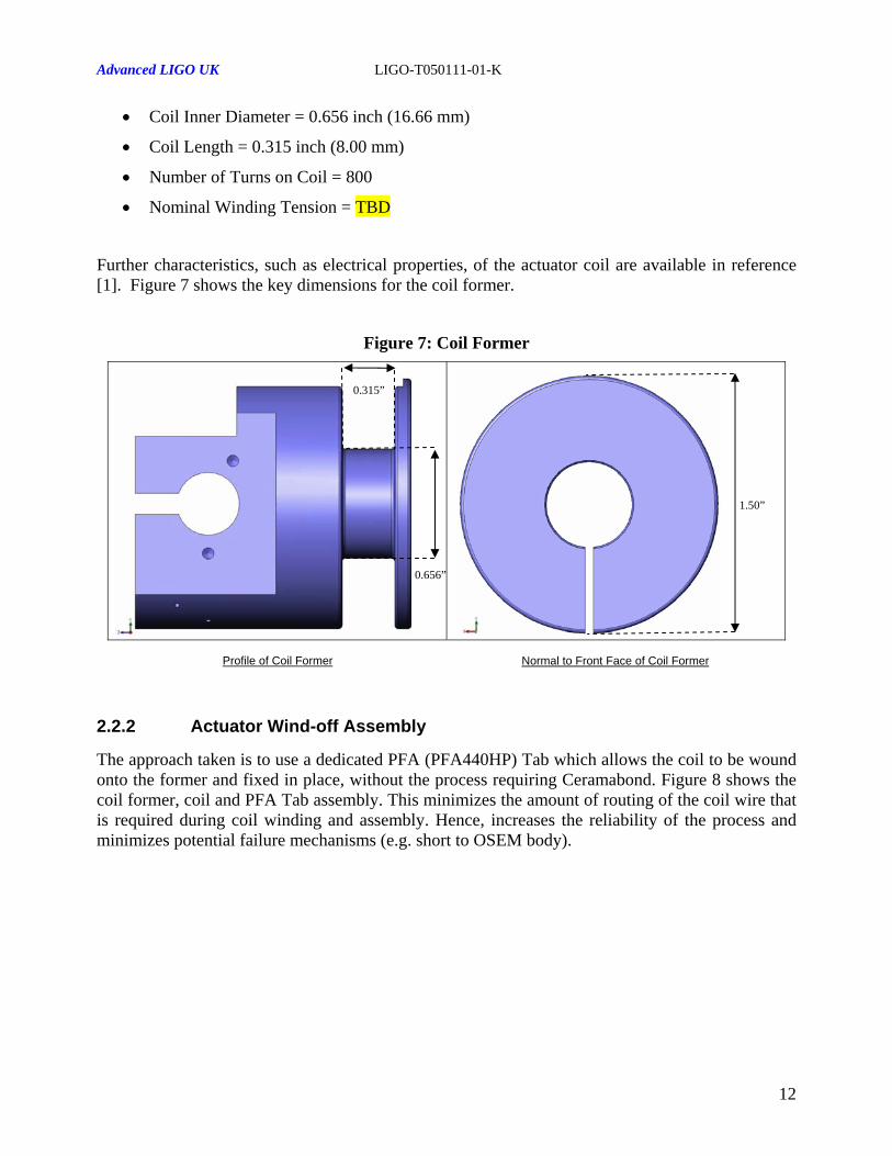
• Coil Inner Diameter = 0.656 inch (16.66 mm)
• Coil Length = 0.315 inch (8.00 mm)
• Number of Turns on Coil = 800
• Nominal Winding Tension = TBD
Further characteristics, such as electrical properties, of the actuator coil are available in reference [1]. Figure 7 shows the key dimensions for the coil former.
Figure 7: Coil Former
0.315”
Normal to Front Face of Coil Former
1.50”
0.656”
Profile of Coil Former
2.2.2 Actuator Wind-off Assembly
The approach taken is to use a dedicated PFA (PFA440HP) Tab which allows the coil to be wound onto the former and fixed in place, without the process requiring Ceramabond. Figure 8 shows the coil former, coil and PFA Tab assembly. This minimizes the amount of routing of the coil wire that is required during coil winding and assembly. Hence, increases the reliability of the process and minimizes potential failure mechanisms (e.g. short to OSEM body).
12

Advanced LIGO UK LIGO-T050111-01-K
Figure 8: Coil Former and Coil Assembly
PFA Tab
Coil Winding
Coil Former
Wind-off Pins
Rear Isometric View
2.3 Magnet and Flag Assembly
The operating point or ‘sweet-spot’ of the magnet and actuator coil has to be recalculated due to the refined coil geometry TBD. This will be calculated using a similar method to that which was used for the Controls Prototype OSEMs, see reference [9]. Suggestions regarding magnet dimensions for stronger actuator forces are discussed in reference [16]. ∅10mm × 10mm long magnets have been selected for TM and UIM locations. ∅2mm × 6mm long magnets have been chosen for the PM. Given that the separation between the sensor and actuator has changed for the Noise Prototype sensor design, new flag dimensions are required. The proposed magnet and flag assembly is shown in Figure 9.
Figure 9: Magnet Flag Assembly
Magnet (∅ 10 × 10 mm)
Spacer (∅ 10 mm)
Magnet Centre Line
0.33” .4 mm(8 ) TBC
1.17” (29.79 mm)
TBC
Flag (∅ 3 mm)
Isometric View of Flag Assembly Section through OSEM and Flag Assemblies
13

Advanced LIGO UK LIGO-T050111-01-K
2.4 Mounting and Adjustment Assemblies
Four mounting locations are available to secure the OSEM to the suspension. These mounts also allow some adjustment to be made in the x and y axes to locate the OSEM. This is described in more detail in the reference [1].
Adjustment is also required axially, along the z-axis. The existing Controls Prototype OSEM design incorporates a “push-pull” assembly to enable the positioning of the coil former along the z-axis. The scheme utilizes four screw fixings, two of which react off the coil former bracket, the other two serve to lock the mechanism against the reacting screws, effectively clamping the coil former in place.
This existing baseline design provides a satisfactory solution but could be developed further. It is possible to remove two of the four screws from the adjustment assembly, whilst still retaining its functionality. For example, a machined shoulder on the coil former back-plate can be machined to an interference fit about a PFA ‘nut’ which is free to travel along a threaded shaft. Figure 10 highlights the key features of this modified assembly. The advantage of this approach is that it makes the OSEM adjustment more intuitive and time saving, since there are only two adjustments to be made.
Figure 10: Adjustment Assembly
PFA Adjustment Nuts Shoulder
Threaded Shaft (5/32-40 ME)
Coil Former Back-Plate
Rear Isometric View
The full axial adjustment range (peak-peak) catered for by this arrangement is 0.44 inches (11.18 mm). This can clearly be seen in Figure 11, where the distance between the plane of the front face of the coil former and the front face of the coil former clamp are coincident on the left figure and displaced on the right figure.
14
Advanced LIGO UK LIGO-T050111-01-K
Figure 11: Axial Adjustment
Profile View of OSEM - Maximum AdjustmentProfile View of OSEM - Nominal Adjustment
0.44” 0.00”
3 OSEM Electrical Overview
3.1 Interconnect Design
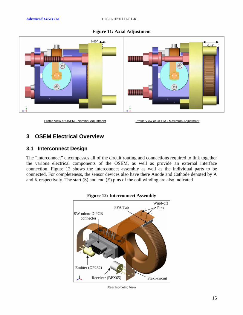
The “interconnect” encompasses all of the circuit routing and connections required to link together the various electrical components of the OSEM, as well as provide an external interface connection. Figure 12 shows the interconnect assembly as well as the individual parts to be connected. For completeness, the sensor devices also have there Anode and Cathode denoted by A and K respectively. The start (S) and end (E) pins of the coil winding are also indicated.
Figure 12: Interconnect Assembly
K
PFA Tab
Flexi-circuit
Emitter (OP232)
Receiver (BPX65)
9W micro-D PCB connector
S
E
A
K
A
Wind-off Pins
Rear Isometric View
15

Advanced LIGO UK LIGO-T050111-01-K
3.1.1 OSEM Connector
The connector located on the OSEM head can be specified as follows:-
• Description: Right angle PCB mounting 9 way male Micro D
• Part Number (GlenAir): MR7590-9P-1BSN-MC225
Modification Code (MC) 225 denotes no marking
The pin-outs of this connector can be found in reference [1]. A materials list for this part can be found in section 5.1 of this document.
3.1.2 Flexi-Circuit
A flexible circuit solution has been developed to replace the discrete wiring harness of the Initial LIGO and Controls Prototype OSEMs. This flexi-circuit forms the foundation of the interconnect assembly. A conventional dual layer flexi-rigid composite circuit is utilized. However, in this application no rigid sections are necessary. A diagram of the multiple layers is shown in figure 13. This double sided structure is approximately 210µm thick.
Figure 13: Flexi-Circuit Multi-Layer Structure
Kapton (25µm) Coverlay
(DuPont LF0110) Adhesive (25µm)
Copper (18µm)
Adhesive (25µm) Copper Clad Laminate
(DuPont LF8515) Kapton (25µm)
Adhesive (25µm)
Copper (18µm)
Coverlay Adhesive (25µm) (DuPont LF0110)
Kapton (25µm)
16
Advanced LIGO UK LIGO-T050111-01-K
3.2 OSEM Cable Harness (Pigtail)
3.2.1 OSEM Mating Connector
The connector mating to the OSEM head can be specified as follows:-
• Description: Straight solder cup 9 way female Micro D
• Part Number (GlenAir): DCDM9S-S-MC194-216-225-240
Modification Code (MC) 194 denotes low profile socket-head jackscrew
Modification Code (MC) 216 denotes part supplied without gasket
Modification Code (MC) 225 denotes no marking
Modification Code (MC) 240 denotes electroless nickel plated shell
The pin-outs of this connector can be found in reference [1]. A materials list for this part can be found in section 5.1 of this document.
3.2.2 SEI Mating Connector
The connector mating to the SEI Table can be specified as follows:-
• Description: Straight solder cup 25 way male Micro D TBC
• Part Number: VAC 25MICRO-25DSUB TBC
The pin-outs of this connector can be found in reference [1]. A materials list for this part can be found in section 5.1 of this document.
3.2.3 OSEM Cable Harness (Pigtail) Lengths
Cable harnessing shall comply with the requirements of reference [10] where appropriate. Each cable harness shall have the following properties:-
• Cable Type: CZ1104 Clear Teflon Coated Copper Wire TBC
• Outer braided shield: (trade-off stiffness vs. shielding requirements TBD)
Cables are to be manufactured to suit the locations of OSEMs within the suspension stages of the 6 TBC different suspension designs. Details in the following sections are TBD pending completion of suspension designs and cable routing proposals. It is expected that there will be no more than TBD different cable lengths.
17

Advanced LIGO UK LIGO-T050111-01-K
Cable clamping details and locations are to be agreed with the SUS design team. Note that any cable lengths given below are the most direct route (no clamping) to the top of the suspension (SEI Table).
3.2.3.1 IMC Triple Suspensions
OSEM Location
Qty OSEM Type
Cable Length
Cable Drawing
Top Mass 6 Noise Prototype
TBD TBD
Penultimate Mass 4 Initial LIGO TBD TBD
Bottom Mass 4 Initial LIGO TBD TBD
Table 3.2.3.1-1
3.2.3.2 OMC Triple Suspensions
OSEM Location
Qty OSEM Type
Cable Length
Cable Drawing
Top Mass 6 Noise Prototype
TBD TBD
Penultimate Mass 4 Initial LIGO TBD TBD
Bottom Mass 4 Initial LIGO TBD TBD
Table 3.2.3.2-1
3.2.3.3 RM Triple Suspension
OSEM Location
Qty OSEM Type
Cable Length
Cable Drawing
Top Mass 6 Noise Prototype
TBD TBD
Penultimate Mass 4 Initial LIGO TBD TBD
Bottom Mass 4 Initial LIGO TBD TBD
Table 3.2.3.3-1
18
Advanced LIGO UK LIGO-T050111-01-K
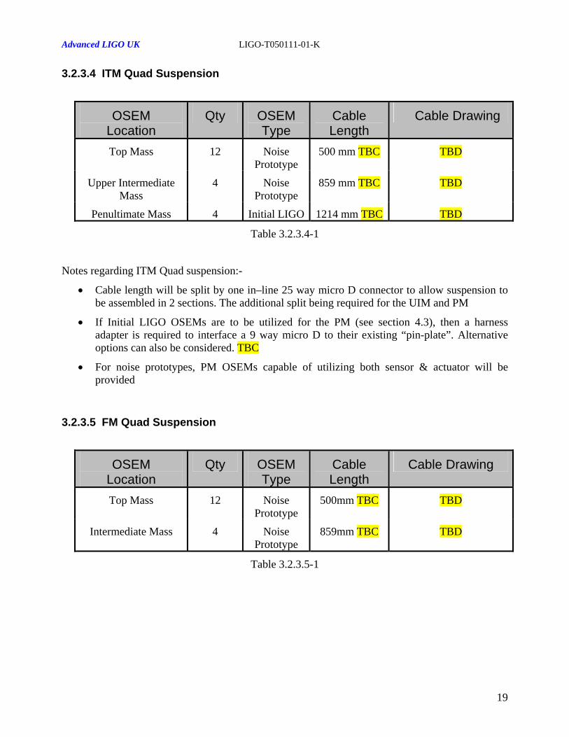
3.2.3.4 ITM Quad Suspension
OSEM Location
Qty OSEM Type
Cable Length
Cable Drawing
Top Mass 12 Noise Prototype
500 mm TBC TBD
Upper Intermediate Mass
4 Noise Prototype
859 mm TBC TBD
Penultimate Mass 4 Initial LIGO 1214 mm TBC TBD
Table 3.2.3.4-1
Notes regarding ITM Quad suspension:-
• Cable length will be split by one in–line 25 way micro D connector to allow suspension to be assembled in 2 sections. The additional split being required for the UIM and PM
• If Initial LIGO OSEMs are to be utilized for the PM (see section 4.3), then a harness adapter is required to interface a 9 way micro D to their existing “pin-plate”. Alternative options can also be considered. TBC
• For noise prototypes, PM OSEMs capable of utilizing both sensor & actuator will be provided
3.2.3.5 FM Quad Suspension
OSEM Location
Qty OSEM Type
Cable Length
Cable Drawing
Top Mass 12 Noise Prototype
500mm TBC TBD
Intermediate Mass 4 Noise Prototype
859mm TBC TBD
Table 3.2.3.5-1
19
Advanced LIGO UK LIGO-T050111-01-K
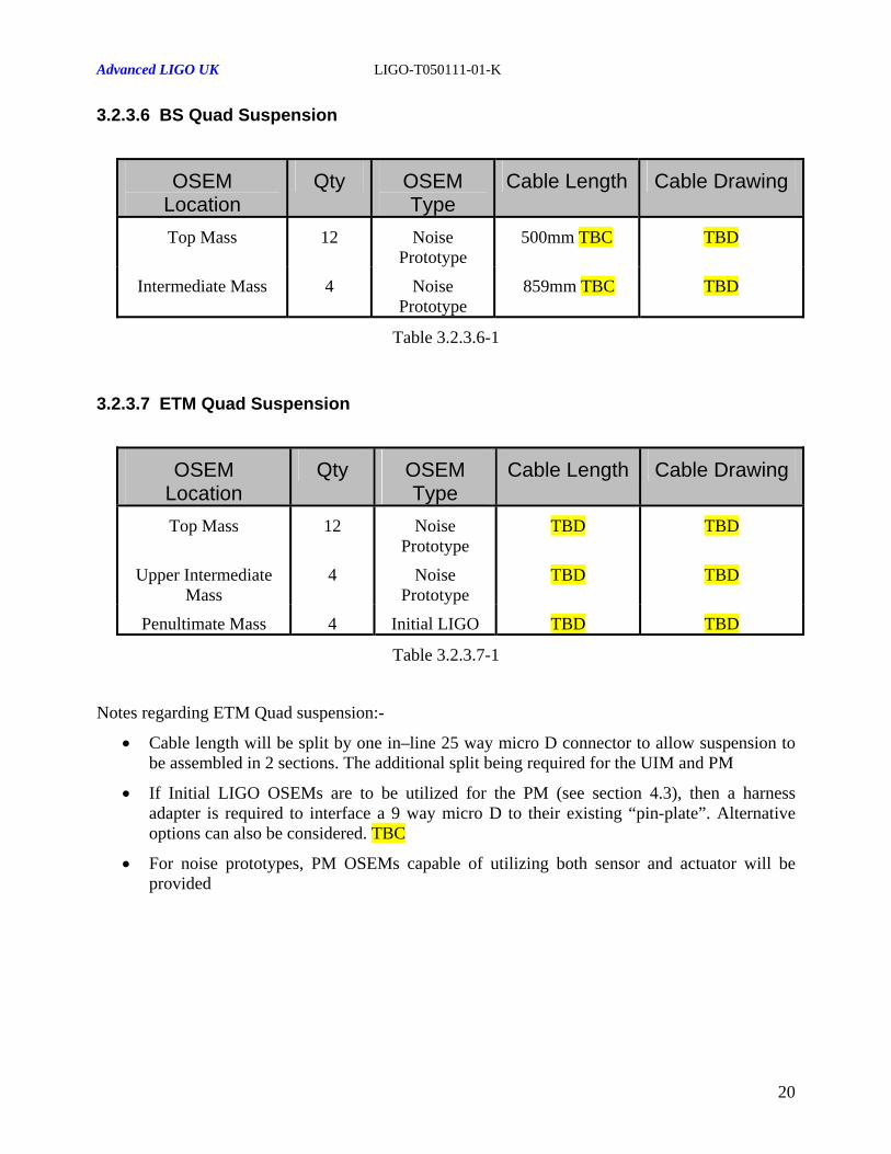
3.2.3.6 BS Quad Suspension
OSEM Location
Qty OSEM Type
Cable Length Cable Drawing
Top Mass 12 Noise Prototype
500mm TBC TBD
Intermediate Mass 4 Noise Prototype
859mm TBC TBD
Table 3.2.3.6-1
3.2.3.7 ETM Quad Suspension
OSEM Location
Qty OSEM Type
Cable Length Cable Drawing
Top Mass 12 Noise Prototype
TBD TBD
Upper Intermediate Mass
4 Noise Prototype
TBD TBD
Penultimate Mass 4 Initial LIGO TBD TBD
Table 3.2.3.7-1
Notes regarding ETM Quad suspension:-
• Cable length will be split by one in–line 25 way micro D connector to allow suspension to be assembled in 2 sections. The additional split being required for the UIM and PM
• If Initial LIGO OSEMs are to be utilized for the PM (see section 4.3), then a harness adapter is required to interface a 9 way micro D to their existing “pin-plate”. Alternative options can also be considered. TBC
• For noise prototypes, PM OSEMs capable of utilizing both sensor and actuator will be provided
20

Advanced LIGO UK LIGO-T050111-01-K
4 OSEM Design Philosophy
4.1 Magnetic Materials Restriction
The use of magnetic materials in the construction of the OSEM shall be restricted to ensure that the residual actuation force (with actuator coil unbiased and actuator magnet positioned on the OSEM z-axis in line with the front face of the coil former) is less than 5mN.
Measurements taken of the magnetic coupling between the metallic packages of the sensor components and the front face of a ∅10mm × 10mm Nd-B-Fe Nickel plated magnet are shown in Figure 14.
Figure 14: Sensor and Actuator Magnetic Coupling
0.0
10.0
20.0
30.0
40.0
50.0
60.0
70.0
80.0
90.0
100.0
10 12 14 16 18 20 22 24Separation (mm)
Forc
e (m
N)
OP232OP232 & BPX65
Dimensions taken from the Noise Prototype OSEM design incorporate 1.126 inch (28.6 mm) separation between the front face of the coil former and the outer diameter of the sensor package, as shown in figure 15.
21

Advanced LIGO UK LIGO-T050111-01-K
Figure 15: Sensor and Actuator Separation
1.126” (28.6 mm)
Emitter Device
Section through Coil Former
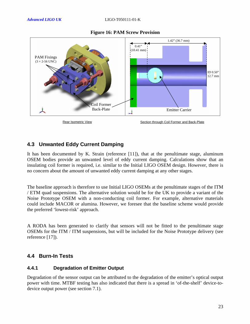
4.2 Pitch Adjustment Magnet (PAM) Provision
The request has been made to include the provision to be able to retro-fit PAM screws to the Noise Prototype OSEM if necessary. It is envisaged that the PAM screw assembly will mount on the rear of the coil former in a similar fashion to how they have been intended to attach to the Initial LIGO OSEMs.
However, even though the length of the new coil former is similar to that of the Initial LIGO coil former, the separation between the sensor and actuator has now increased. Initial LIGO PAMs used small (approximately ∅3mm) magnets, with an operating point approximately 10mm away from the front face of the magnet / flag assembly. The proximity of the PAM magnet and magnet / flag assembly are restricted in our scheme by the sensor assembly. Hence, a larger aperture has been opened out at the rear of the Noise Prototype OSEM design, in the coil former back-plate, as can be seen in Figure 16. This is to accommodate a large (∅10mm) PAM magnet if necessary. Measurements suggest a bias force of approximately 100mN is achievable, at closest approach between two ∅10mm × 10mm magnets.
22
Advanced LIGO UK LIGO-T050111-01-K
Figure 16: PAM Screw Provision
Coil Former Back-Plate Emitter Carrier
0.41” (10.41 mm)
1.42” (36.7 mm)
PAM Fixings (3 × 2-56 UNC)
ID 0.50” 12.7 mm
Rear Isometric View Section through Coil Former and Back-Plate
4.3 Unwanted Eddy Current Damping
It has been documented by K. Strain (reference [11]), that at the penultimate stage, aluminum OSEM bodies provide an unwanted level of eddy current damping. Calculations show that an insulating coil former is required, i.e. similar to the Initial LIGO OSEM design. However, there is no concern about the amount of unwanted eddy current damping at any other stages.
The baseline approach is therefore to use Initial LIGO OSEMs at the penultimate stages of the ITM / ETM quad suspensions. The alternative solution would be for the UK to provide a variant of the Noise Prototype OSEM with a non-conducting coil former. For example, alternative materials could include MACOR or alumina. However, we foresee that the baseline scheme would provide the preferred ‘lowest-risk’ approach.
A RODA has been generated to clarify that sensors will not be fitted to the penultimate stage OSEMs for the ITM / ITM suspensions, but will be included for the Noise Prototype delivery (see reference [17]).
4.4 Burn-In Tests
4.4.1 Degradation of Emitter Output
Degradation of the sensor output can be attributed to the degradation of the emitter’s optical output power with time. MTBF testing has also indicated that there is a spread in ‘of-the-shelf’ device-to-device output power (see section 7.1).
23

Advanced LIGO UK LIGO-T050111-01-K
The burn-in process ‘over-rates’ the devices by running them at their maximum specified forward current of 100mA i.e. above the nominal operating value of 35mA. The duration of the burn-in process is TBD. This burn-in process minimizes the risk of premature OSEM failure by also providing a test for infant mortality of the devices. The format of this test is TBD.
4.4.2 Breakdown of Coil Winding
For previous OSEM design, concerns have been raised over the breakdown of the coil winding insulation. It is therefore required that ‘burn-in’ tests are carried out on the wound coil former to immediately identify any failures. The format of the burn-in test is that a high potential (approximately 1kV TBC) is applied across the coil for a duration of TBD.
However, on the fully assembled Noise Prototype OSEM, the maximum potential that can be applied across the coil winding is limited by the breakdown voltage specified for the micro D connector, i.e. 300V. TBC
4.5 Thermal Considerations
The OSEM shall function under the following environmental conditions:-
• Operational Temperature: 220C (nominal ambient) TBC
• Seasonal Variation: 20C (between sites) TBC
The Maximum dissipation from the OSEM shall be as follows:-
Item Maximum Dissipated Power Notes Coil 833mW At 150mA continuous forward current
IRLED 50mW At 35mA continuous forward current
Table 4.5-1
Note: The Detector diode dissipation is considered negligible
24

Advanced LIGO UK LIGO-T050111-01-K
5 UHV Requirements
5.1 Material List and UHV Conformance
Table 5.1-1 following, lists all materials used in the OSEM manufacture, including connectors, electronic components and cable harness (pigtail). Reference [12] provides a list of LIGO compatible materials and reference [13] gives details of the queue for acceptance testing.
Item Material Where Used
Vacuum Review Board Approval
Status 1 Beryllium Copper
(ASTM-B194) Male Connector
Approved
2 Phosphor Bronze (ASTM 139)
Female Connector and Emitter Lens Carrier
Approved
3 Gold
(ASTM-B488)
Connector pin/socket Plating
Approved
4 Aluminium (Alloy 6082)
see T050171-01
Connector Body, Coil Former, Mounting Plates
Approved
5 Electroless Nickel
(ASTM B733-90,SC2,Type 1, Class J
(MIL-C-26074)
Connector Body Finish
Approved
6 LCP (MIL-M-24519) Connector Insulators and Inserts
Approved
7 Hysol Epoxy #4215 (Black)
Connector Encapsulant
Approved
8 Stainless Steel (300 per SAE-AMS-QQ-S-763)
Connector Jackscrews and Posts
Approved
9 Copper Wire (32QML) Coil Winding 32HML Initial LIGO Approved
10 Copper Wire (CZ1104) Pigtail Approved (initial LIGO)
11 Kapton (LF0110)
Copper Clad (LF8515)
Flex Rigid PCB
Approved TBC
12 Teflon PFA-440HP (DuPont)
Sensor Carrier Locking Ring
Approved (Initial LIGO)
25

Advanced LIGO UK LIGO-T050111-01-K
13 Titanium Adjustment Assembly and Sensor Carrier
Approved
14 OP232 IRLED Approved
15 BPX65 PD Approved
Table 5.1-1
5.2 OSEM Cleaning Procedure
The cleaning procedure proposed for the noise prototype OSEM is as follows:-
• Pre-clean all parts (ultrasonic bath)
• Kapton wire to be wiped with Isopropyl alcohol (IPA) during winding onto the coil former
• Wound coils (and coil former) are to be vacuum baked (approximately 200C) and RGA checked (this process could possibly be undertaken by LIGO TBD)
• LED emitter and PD receiver vacuum baked at a lower temperature
• Other metal parts baked at high temperature
• OSEMs assembled according to UHV handling procedures
• The completed assemblies are low temperature vacuum baked and RGA checked upon arrival at LIGO *
(n.b. the above procedure is not consistent with the cleaning procedure as presented in references [13] and [14]. TBC).
* It has been requested the temperature of this final stage bake-out be elevated. The existing upper temperature for this process is limited by the demagnetization of the standard magnets. Alternative grades of ND35 magnets are available that would raise there operational temperatures to 120 0C, 150 0C and 180 0C. Procurement options are currently under consideration TBC. It is therefore necessary to specify limits that apply to the maximum bake-out temperature, due to materials used in the construction of the Noise Prototype OSEM. These are as follows:-
• BPX65 and OP232 sensor devices. Storage temperatures of 125 0C and 150 0C are quoted for each device, respectively.
• Glenair micro-D connector. Operating temperature up-to 150 0C.
• Flexi-circuit interconnect. Circuit layers will begin to delaminate when adhesive reaches over 182C.
• Teflon PFA-440HP (Dupont). Upper service temperature of 260 0C.
26

Advanced LIGO UK LIGO-T050111-01-K
6 OSEM Support Equipment
6.1 Automatic Test Equipment
Due to the volume of devices to be manufactured, finished product setup and test will be assisted by a PC based automated test system. The system will measure and record the following parameters:-
• Actuator Winding Inductance
• Actuator Winding Resistance
• Actuator Winding isolation to OSEM body
• Sensor Current Transfer Ratio
• Sensor Emitter isolation to OSEM body
• Sensor Detector isolation to OSEM body
Test results will be provided with the finished product.
27
Advanced LIGO UK LIGO-T050111-01-K
7 Test Results
7.1 Off-Axis Emission
The potential issue of OP232 IRLEDs radiating with appreciable off-axis beam patterns has been raised and addressed in a report by N. Lockerbie (reference [15]). The outcome of this investigation was that the IRLEDs off-axis emission is not a concern.
7.2 Emitter MTBF Results
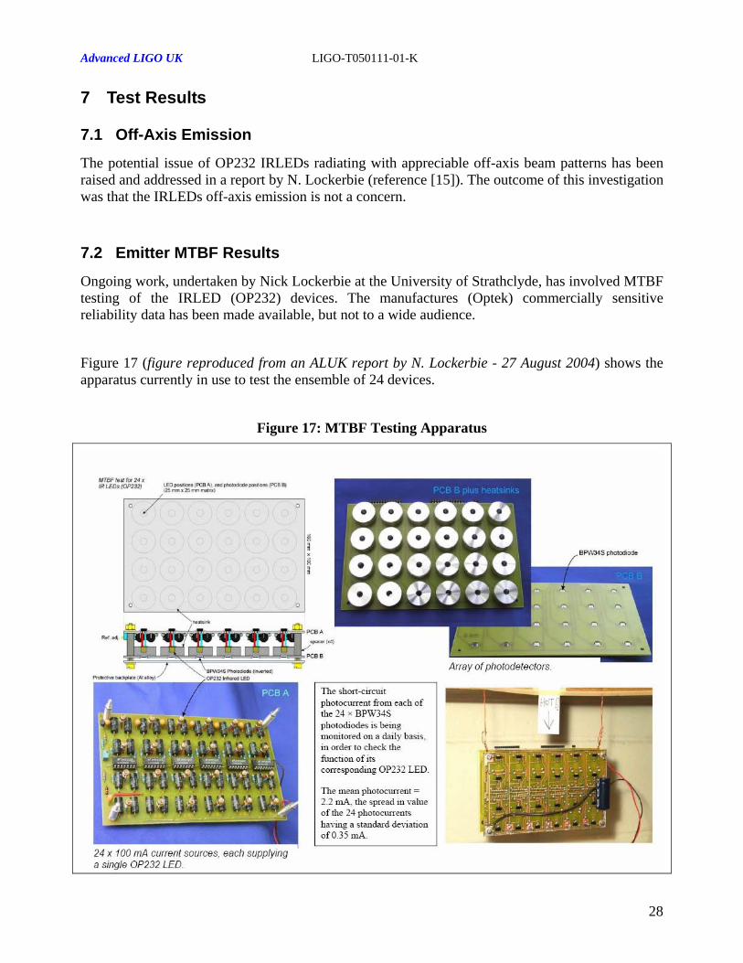
Ongoing work, undertaken by Nick Lockerbie at the University of Strathclyde, has involved MTBF testing of the IRLED (OP232) devices. The manufactures (Optek) commercially sensitive reliability data has been made available, but not to a wide audience.
Figure 17 (figure reproduced from an ALUK report by N. Lockerbie - 27 August 2004) shows the apparatus currently in use to test the ensemble of 24 devices.
Figure 17: MTBF Testing Apparatus
28

Advanced LIGO UK LIGO-T050111-01-K
Figure 18: MTBF Test Results
Figure 18 (figure provided by N. Lockerbie) shows the degradation of the induced mean photocurrent in the 24 x BPW34S’s over 13000 hours. At the present time, after over 13000 hours of running, the mean photocurrent induced in the photodiodes has now fallen to 62% of the 'day 1' value. None of the devices has failed to-date. We define the failure condition to be when a device output level falls to 50% of its initial value. It should be noted that these tests are being conducted at the maximum allowable forward current of 100mA, whereas the nominal current we intend to use is around 35mA.
The manufactures model of optical output degradation over time has been broadly validated by the testing that has so far been conducted. Extrapolating from this model would lead estimates of the device MTBF being TBD hours. Note that these estimates are extremely conservative and do not include scaling the MTBF when de-rating the device.
29

Advanced LIGO UK LIGO-T050111-01-K
7.3 Prototype OSEM Fabrication
To enable a function and fit check of the Noise Prototype OSEM design, a prototype device has been fabricated and assembled. This prototype device will enable us to assess the ‘new’ features of the design (e.g. the revised adjustment assembly) and also allow us to verify the sensitivity performance (and operating range) of the sensor.
Figure 19, shows the pictures of the fully assembled coil former and OSEM assemblies. The prototype units constructed utilized oversize taps for all taps in aluminum parts, as required for the Noise Prototype devices (reference [13]).
Figure 19: OSEM Prototype Assembly
Fully Populated Coil Former
Fully Assembled OSEM30

Advanced LIGO UK LIGO-T050111-01-K
7.4 Prototype OSEM Performance
7.4.1 Operating Range
Figure 20: Measured OSEM Detector Response
-15.00
-10.00
-5.00
0.00
5.00
10.00
15.00
0 200 400 600 800 1000 1200 1400
Displacement (um)
Diff
eren
tial o
/p V
olta
ge (V
)
0.7mm
Gradient in region of linear response = 23.320kV/m
TBC
31

Advanced LIGO UK LIGO-T050111-01-K
7.4.2 Sensitivity Performance
0 2 4 6 8 10 12 14 16 18 20 22 24 26120
115
110
105
100
95
90
85Trace Plot
Frequency (Hz)
dBV
rms/
rtHz
A 1⟨ ⟩
A 0⟨ ⟩
TBD
7.4.3 In-Vacuum Thermal Test Results
TBD
32


