Embed Size (px)
Citation preview

CHAPTER 3
OSCILOSCOPE AND
SIGNAL CONDITIONING

Introduction to Signal Generator
Oscillator
Requirement for Oscillation
Positive Feedback Amplifier
Oscillator
Radio Frequency Oscillator
OUTLINE
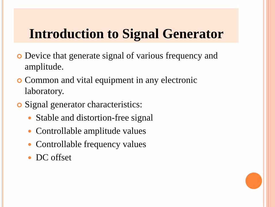
Introduction to Signal Generator
Device that generate signal of various frequency and
amplitude.
Common and vital equipment in any electronic
laboratory.
Signal generator characteristics:
Stable and distortion-free signal
Controllable amplitude values
Controllable frequency values
DC offset

Types of signal generator:
Standard Signal Generator
Audio Signal Generator
Radio-Frequency Signal Generator
Function Generator
Pulse Generator
Sweep Generator
Random Noise Generator
Introduction to Signal Generator Cont’d

Oscillator is a circuit that generates an ac output signal
without requiring any externally applied output signal.
The only input power to an oscillator is the d.c power
supply.
Term ‘Oscillator’ is generally used for an instrument that
provides only a sinusoidal output signal, and the term
‘generator’ is applied to an instrument that provides
several output waveforms, including sine wave, square
wave, triangular wave and pulse trains as well as
amplitude modulation of the output signal.
OSCILLATOR

ADVANTAGES:
An oscillators is a non-rotating device. Consequently,
there is little wear and tear and hence longer life.
Due to the absence of moving parts, the operation of
an oscillator is quite silent.
An oscillator can produce waves from 20 Hz to
extremely high frequencies 100 MHz
The frequency of oscillations can be easily changed
when desired.
It has good frequency stability.
It has very high efficiency.
OSCILLATOR CONT’D

Basically, an oscillator is an amplifier with positive
feedback.
The signal regenerate and sustain itself.
The gain equation for an amplifier with positive
feedback is:
Where:
REQUIREMENTS FOR OSCILLATION
s
of
V
V
A
AA
1
Af = gain with feedback
A = open-loop gain
β = feedback factor, Vi/Vo

Gain for amplifier with positive feedback:
REQUIREMENTS FOR OSCILLATION
CONT’D
A
B
Vs+
-
VoOutput
Signal
Input
Signal
Feedback
Signal
Vf = βVo
Vi = Vs - Vf
Closed-loop system consisting of amplifier with feedback

POSITIVE FEEDBACK AMPLIFIER
OSCILLATOR CONT’D
A transistor amplifier with proper positive feedback can
act as an oscillator. You must remember that a positive
feedback amplifier is the one that produces a feedback
voltage, Vf that is in phase with the original input signal.

A phase shift of 180° is produced by the amplifier and a further phase shift of 180° is introduced by feedback network.
The signal get shifted by 360°.
This signal is then feedback to the input. The feedback voltage is in phase with the input signal.
The circuit is producing oscillations in the output.
However, this circuit has an input signal. But, then this is inconsistent with our definition of an oscillator which states that an oscillator is a circuit that produces oscillations without any external signal source.
POSITIVE FEEDBACK AMPLIFIER
OSCILLATOR

If we open the switch S in the figure, we will get the circuit as shown:
It means that the input signal is removed. However, the feedback voltage is still applied to the input signal. The amplifier will respond to this signal in the same way that it did to the input signal and that is the feedback voltage will be amplified and sent to the output.
The function of the feedback network is to send a portion of the output back to the input. Therefore, the amplifier receives another input cycle and another output cycle is produced. This process will continue so long as the amplifier is turned on.
Therefore, the amplifier will produce sinusoidal output with no external signal source.
POSITIVE FEEDBACK AMPLIFIER
OSCILLATOR

If a negative-feedback circuit has a loop gain that
satisfies two conditions:
POSITIVE FEEDBACK AMPLIFIER
OSCILLATOR CONT’D
Loop Gain, Aβ ≥ 1 Net Phase Shift = 0 @ Phase Aβ = 0
Barkhausen
Criteria

Oscillator categorized in two types:
i) Audio Oscillators
ii) Radio Frequency Oscillators
There are two common types of Audio Oscillators:
i)Wien Bridge Oscillator
ii) Phase-Shift Oscillator
Both of which employ RC feedback network
The Wien Bridge offers some very attractive features,
including a straightforward design, a relatively pure
sine-wave output and very stable frequency
TYPES OF OSCILLATOR

There are of many types of radio frequency, but
the famous is HARTLEY OSCILLATOR.
Radio frequency must satisfy the same basic
criteria for oscillation, that is Barkhausen
criteria.
The phase-shift network for RF oscillators is an
inductance-capacitance (LC) network.
This LC combination which generally referred to
as a tank circuit, acts as a filter to pass the
desired oscillating frequency and block all other
frequencies.
RADIO FREQUENCY OSCILLATOR

RADIO FREQUENCY OSCILLATOR
CONT’D
15
Hartley oscillator
LCf
2
1
Frequency of oscillation,
2
1
L
L
Feedback factor, β
L = L1 + L2
Solve the equation for inverting
Amplifier
1
21
L
LA
i
f
R
RA
Barkhausen Criteria, Aβ ≥ 1 to
sustain oscillation

EXAMPLE 1
Determine the frequency of oscillation and the minimum value of
Rf to sustain oscillation for the Hartley oscillator shown in figure:
R
Ri=15k
Rf
L1=10µH L2=270µHC=0.001µF
+Vcc
+Vcc
-
+

SOLUTION

EXAMPLE 2
Determine the minimum value of Rf in figure below to
sustain oscillation if L2=125µH
R
Ri=10kΩ
Rf
L1=15µH L2C=0.015µF
+Vcc
+Vcc
-
+

SOLUTION

EXAMPLE 3
Determine the value of L2 in the circuit below if the
frequency of oscillation is to be 100kHz
R
Ri=10kΩ
Rf
L1=15µH L2C=0.015µF
+Vcc
+Vcc
-
+

SOLUTION

END OF CHAPTER 3