Embed Size (px)
Citation preview

Oscillator Design with Genesys
with techniques from the book
Discrete Oscillator
Design:linear, nonlinear, transient and noise
domains
by Randy Rhea

Slide 2
I'll Cover
• A unified design process for different active devices,
resonators and simulation technologies applicable from low
frequency to microwaves
• How Genesys aids the design process
• What the book offers
• Example Genesys workspaces
Slide 2
Randy Rhea Susina LLC
[email protected] Sept 16, 2010

Slide 3
Step 1
Perform a linear analysis
• This is the design foundation
– determines design margins
– reveals tuning characteristics
– estimates phase noise
– fast exploration of topologies
• Provides intuitive grasp of the design process
• Does not provide level, harmonic or transient data
Slide 3
Randy Rhea Susina LLC
[email protected] Sept 16, 2010

Slide 4
Two Linear Analysis Methods
• One-Port Reflection
AMPLIFIERRESONATOR
LOOP_INPUT LOOP_OUTPUT
OSCILLATOR_OUTPUT
• Open-Loop Cascade
RESONATOR DEVICE
REFLECTION_PORT OSCILLATOR_OUTPUT
Randy Rhea Susina LLC
[email protected] Sept 16, 2010

Slide 5
The Open-Loop Cascade
Slide 5
Initial 40 MHz Colpitts with a FET device and an L-C resonator
50ΩOscOut
.01μF
C4
LoopOutLoopIn
270nH
L1
0.011A
CP1
J310
5V
180pF
C3
180Ω
R2
27ΩR1
74.7pF
C1
180pF
C2
Randy Rhea Susina LLC
[email protected] Sept 16, 2010

Slide 6
Oscillator Starting Conditions
Slide 6
Randy Rhea Susina LLC
[email protected] Sept 16, 2010
The open-loop response criterion that insure the oscillator will start are
• The oscillation frequency is the transmission phase zero-crossing, f0
• The initial linear gain at f0
must be greater than 0 dB
• The phase slope at f0
must be negative
Additional objectives are
• The phase slope should be as steep as possible
• The maximum phase slope occurs at f0
• The gain margin at f0
is moderate, for example 3 to 8 dB
• The amplifier is stable
• The maximum gain margin occurs at f0
• S11 and S22 are small

Slide 7
Initial Linear Cascade Response
Slide 7
Initial 40 MHz Colpitts transmission and reflection responses
Frequency (MHz)
S21 (
dB
)
0
3
6
9
12
15
18
QL, S
21 a
ng
-90
-60
-30
0
30
60
90
Frequency (MHz)
38 39 40 41 42
S21QLS21 ang
0
0.1
0
.2
0.3
0
.4
0.5
0
.6
0
.7
0.8
0
.9
1.0
1.2
1
.4
1.6
1.8
2.0
3.0
4.0
5.0
1
0
20
0.1
0.2
0.3
0.4
0.5
0.6
0.7
0.8 0
.9 1.0
1.2
1.4
1. 6
1. 8
2.0
3.0
4.0
5 .0
10
20
50
0. 2
0.4
0. 6
0.8
1.0
0.2
0.4
0.6
0.8
1.0
0 .1
0.2
0.3
0.4
0.5
0. 6
0.7
0.8
0.9
1.0 1
.2
1.4
1.6
1.8
2.0
3.0
4.0
5.0
10
20
50
0.2
0.4
0.6
0.8
1.0
0.2
0 .4
0.6
0.8
1 .0
S11
S22
40MHz: -12.735dB, -167.772°
40MHz: -0.344dB, 12.728°
Randy Rhea Susina LLC
[email protected] Sept 16, 2010

Slide 8
Randall/Hock Correction
1212212211
1221
21 SSSSS
SSG
Slide 8
G is the true open-loop complex gain with the loop self-
terminated.
[1] M. Randall and T. Hoch, "General Oscillator Characterization Using Linear Open-
Loop S-Parameters," IEEE Trans. MTT, Vol. 49, June 2001, pp 1094-1100
Randy Rhea Susina LLC
[email protected] Sept 16, 2010
Slide 10
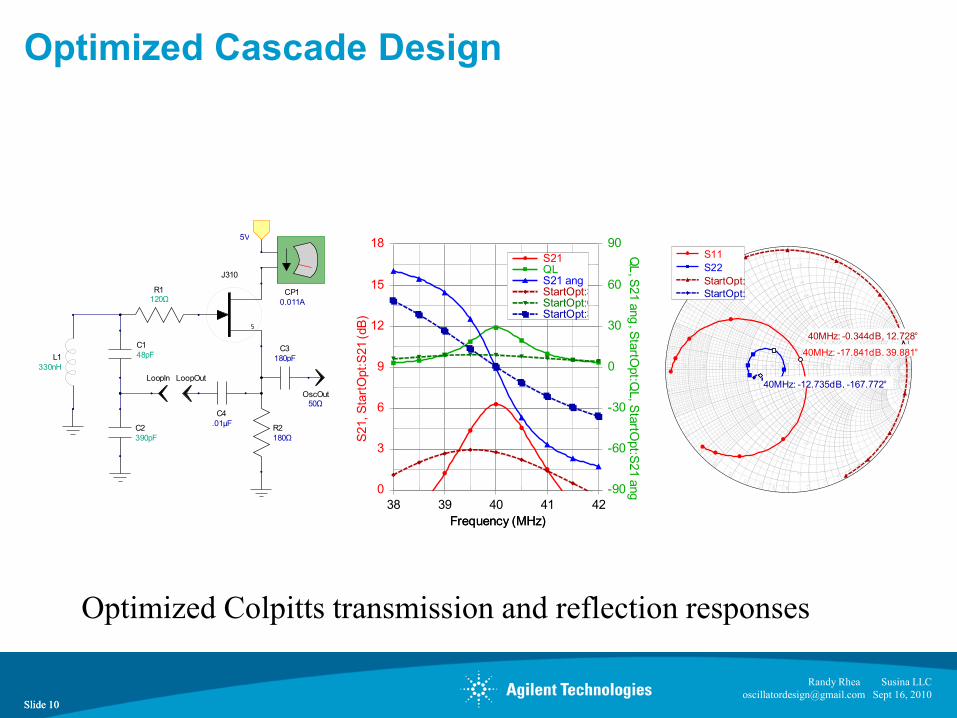
Optimized Cascade Design
Slide 10
Optimized Colpitts transmission and reflection responses
50ΩOscOut
.01μF
C4
LoopOutLoopIn
330nH
L1
0.011A
CP1
J310
5V
180pF
C3
180Ω
R2
120ΩR1
48pF
C1
390pF
C2
Frequency (MHz)
S21, S
tart
Opt:
S21 (dB
)
0
3
6
9
12
15
18
QL
, S21
ang
, Sta
rtOpt:Q
L, S
tartO
pt:S
21 a
ng-90
-60
-30
0
30
60
90
Frequency (MHz)
38 39 40 41 42
S21QLS21 angStartOpt:S21StartOpt:QLStartOpt:S21 ang
0
0.1
0
.2
0.3
0
.4
0.5
0
.6
0
.7
0.8
0
.9
1.0
1.2
1
.4
1.6
1.8
2.0
3.0
4.0
5.0
1
0
20
0.1
0.2
0.3
0.4
0.5
0.6
0.7
0.8 0
.9 1.0
1.2
1.4
1. 6
1. 8
2.0
3.0
4.0
5 .0
10
20
50
0. 2
0.4
0. 6
0.8
1.0
0.2
0.4
0.6
0.8
1.0
0 .1
0.2
0.3
0.4
0.5
0. 6
0.7
0.8
0.9
1.0 1
.2
1.4
1.6
1.8
2.0
3.0
4.0
5.0
10
20
50
0.2
0.4
0.6
0.8
1.0
0.2
0 .4
0.6
0.8
1 .0
S11
S22
StartOpt:S11
StartOpt:S22
40MHz: -12.735dB, -167.772°
40MHz: -0.344dB, 12.728°
40MHz: -17.841dB, 39.881°
Randy Rhea Susina LLC
[email protected] Sept 16, 2010

Slide 11
Alechno Technique
Slide 11
Randy Rhea Susina LLC
[email protected] Sept 16, 2010
[1] S. Alechno, "The Virtual Ground in Oscillator Analysis – A Practical Example",
Applied Microwave & Wireless, July 1999, pp.44-53

Slide 12
Back when…….
• A random combination of a device and resonator may not satisfy the starting criterion
• Historically, successful combinations were named for the discoverer and became standards
• Copying designs was (and is!) common, often resulting in nonoptimum performance
• Modern linear, nonlinear and transient simulation is a better method that improves designs
Slide 12
Randy Rhea Susina LLC
[email protected] Sept 16, 2010

Slide 13
Unified Approach
• These techniques are general
• All resonator or device types are treated in a like manner
• In Genesys, the same schematic is used for linear, nonlinear,
transient and noise simulation
• Ideal or real models are treated in a like manner
Slide 13
Randy Rhea Susina LLC
[email protected] Sept 16, 2010

Slide 14
Step 2
Perform a harmonic-balance simulation
• This determines the output level and harmonics
• Predicts noise more accurately
• Predicts the frequency more accurately
Requires nonlinear device models
• Numerous models are provided with Genesys
• Genesys imports Spice models
• Devices can also be characterized by
X-parameters
Slide 14
Randy Rhea Susina LLC
[email protected] Sept 16, 2010

Slide 15
330 MHz Colpitts & Spectrum
Slide 15
330 MHz Colpitts simulated through the 7th harmonic
0.02ACP1
BFT92
Port_2
Port_3
9V
20pFC1
Port_136pFC2
2700Ω
R1
4700Ω
R2
47pFC3
270pF
Csimulation
150ΩR3
FB
27Ω
10pF
C4
120
16.16nHL1
1 2 3
Open_Loop
50Ω
Output1.155V
330.028MHz
OSCPORT
Frequency (MHz)
Po
ut (
dB
m)
-50
-40
-30
-20
-10
0
10
Frequency (MHz)
0 330 660 990 1320 1650 1980 2310
Pout
330.0
28 M
Hz
8.321 dBm
1*330.028
Randy Rhea Susina LLC
[email protected] Sept 16, 2010

Slide 17
Nonlinear Noise Analysis Plot
Slide 17
4 most significant noise contributors of the 330 MHz Colpitts bipolar oscillator
Frequency (MHz)
Q1 B
ase, O
utp
ut Therm
al, Q
1 C
olle
cto
r, F
B (dB
)
-190
-180
-170
-160
-150
-140
-130
-120
-110
-100
-90
-80
-70
Frequency (MHz)
100e-6 1e-3 0.01 0.1 1 10 100
Q1 Base
Output Thermal
Q1 Collector
FB
Randy Rhea Susina LLC
[email protected] Sept 16, 2010

Slide 18
Step 3
Perform a time-step transient analysis
• This determines the starting characteristics
• This helps discover transient spurious modes
• Can be used as a substitute to HB to find output level and harmonics if
nonlinear noise estimates are not required
Uses the same models as HB simulation
Slide 18
Randy Rhea Susina LLC
[email protected] Sept 16, 2010
1
50Ω
Output
1 2 3
Data_Linear1

Slide 19
Output Waveform
Slide 19
330 MHz Colpitts transient starting waveform
Time (ns)
VP
OR
T (
V)
-2
-1.6
-1.2
-0.8
-0.4
0
0.4
0.8
1.2
1.6
2
Time (ns)
0 20 40 60 80 100 120 140 160 180 200
Randy Rhea Susina LLC
[email protected] Sept 16, 2010
0.02ACP1
BFT92
Port_2
Port_3
9V
20pFC1
Port_136pFC2
2700Ω
R1
4700Ω
R2
47pFC3
270pF
Csimulation
150ΩR3
FB
27Ω
10pF
C4
120
16.16nHL1

Slide 21
Genesys is
• An integrated linear, nonlinear, transient, noise simulation
environment with schematic and layout tools
• A process for creating new oscillator designs or repairing under
performing designs
• A learning tool that provides intuitive insight into all aspects of
oscillator behavior
Slide 21
Randy Rhea Susina LLC
[email protected] Sept 16, 2010

Slide 22
Oscillator Topics Not Covered in this Webinar
• Genesys oscillator synthesis
• Integrated layout tools
• Electromagnetic simulation of the layout
• Instrument control for data acquisition
• System simulation
Slide 22
Randy Rhea Susina LLC
[email protected] Sept 16, 2010

Slide 23
Why Did I Write the Book?
• My previous books only covered nonlinear
and transient theory qualitatively
• I gained knowledge while teaching an
oscillator design course to over a thousand
engineers
• Both oscillator and simulation technologies
have advanced significantly in the last decade
• I needed something to do
Slide 23
Randy Rhea Susina LLC
[email protected] Sept 16, 2010

Slide 24
What's in the Book ?
• Detailed descriptions of linear, nonlinear, transient and noise
techniques for practical oscillator design
• 350 illustrations
• 200 applicable equations
• 60 example oscillators covering bipolar,
FET, and MMIC devices with R-C, L-C,
ceramic, crystal, SAW and distributed
resonators
• Confirmation data for a dozen
prototype oscillators
Slide 24
Randy Rhea Susina LLC
[email protected] Sept 16, 2010

Slide 25
Genesys Workspaces
140 Genesys workspaces were used to create the illustrations in the book. Genesys is a powerful documentation tool.
• Agilent EEsof EDA has established a website for downloading 73 of the more important workspaces
• These workspaces may be used with either full or trial Genesys licenses
Slide 25
Randy Rhea Susina LLC
[email protected] Sept 16, 2010

Slide 26
The Available Workspaces
• The workspace template.wsx may be used to start a design. Simply add your schematic to the workspace
• There are 13 utility and tutorial workspaces for amplifier and resonator design
• There are 27 workspaces for general purpose oscillators
• There are 13 workspaces of VCOs and distributed resonator oscillators
• There are 20 workspaces with ceramic, crystal and SAW oscillators
Slide 26
Randy Rhea Susina LLC
[email protected] Sept 16, 2010

Slide 27
Summary
• Genesys is an integrated tool, ideally suited for a unified
approach to oscillator design
• Discrete Oscillator Design covers practical oscillator design for
a wide variety of oscillator types
• Example Genesys workspaces from the book are available
from Agilent EEsof
Slide 27
Randy Rhea Susina LLC
[email protected] Sept 16, 2010

Slide 28
For More Info: Just Google “Agilent Genesys”
Email Randy Rhea at [email protected]
• for questions about this presentation• for questions about the book• for a Microsoft Excel spreadsheet of equations in the book• for an errata sheet for the book, as published
About Genesys:• Genesys product page http://www.agilent.com/find/eesof-genesys• USA Genesys Specialist, Rick Carter [email protected]
To download the workspaces:• Go to http://www.agilent.com/find/eesof-genesys-osc-workspaces
To obtain a free trial Genesys license:• Go to http://www.agilent.com/find/eesof-genesys-evaluation
Slide 28
Randy Rhea Susina LLC
[email protected] Sept 16, 2010