Embed Size (px)
Citation preview
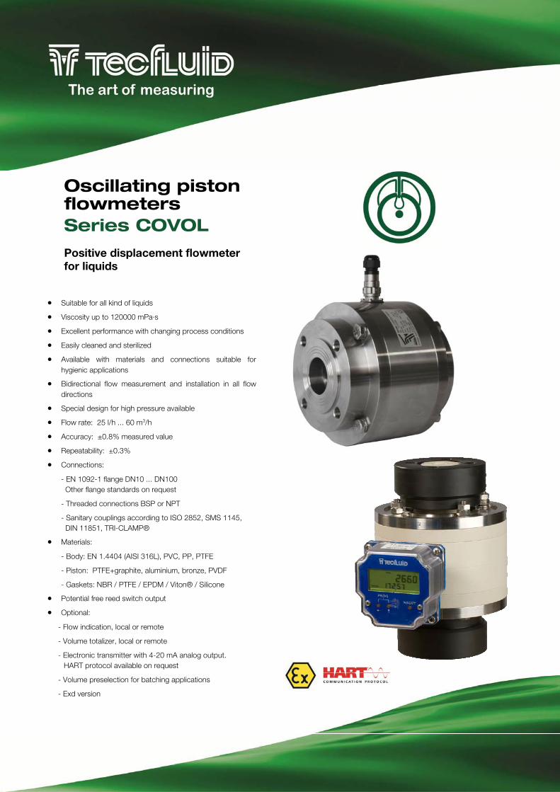
Suitable for all kind of liquids
Viscosity up to 120000 mPa·s
Excellent performance with changing process conditions
Easily cleaned and sterilized
Available with materials and connections suitable for hygienic applications
Bidirectional flow measurement and installation in all flow directions
Special design for high pressure available
Flow rate: 25 l/h ... 60 m3/h
Accuracy: ±0.8% measured value
Repeatability: ±0.3%
Connections:
- EN 1092-1 flange DN10 ... DN100 Other flange standards on request
- Threaded connections BSP or NPT
- Sanitary couplings according to ISO 2852, SMS 1145, DIN 11851, TRI-CLAMP®
Materials:
- Body: EN 1.4404 (AISI 316L), PVC, PP, PTFE
- Piston: PTFE+graphite, aluminium, bronze, PVDF
- Gaskets: NBR / PTFE / EPDM / Viton® / Silicone
Potential free reed switch output
Optional:
- Flow indication, local or remote
- Volume totalizer, local or remote
- Electronic transmitter with 4-20 mA analog output. HART protocol available on request
- Volume preselection for batching applications
- Exd version
Oscillating piston flowmeters Series COVOL
Positive displacement flowmeter for liquids
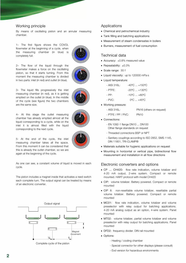
Working principle By means of oscillating piston and an annular measuring chamber.
1– The first figure shows the COVOL flowmeter at the beginning of a cycle, when the measuring chamber (in blue) is completely full.
2– The flow of the liquid through the flowmeter makes a force on the oscillating piston, so that it starts turning. From this moment the measuring chamber is divided in two parts: inlet (in red) and outlet (in blue).
3– The liquid fills progressively the inlet measuring chamber (in red), as it is getting emptied on the outlet (in blue). In the middle of the cycle (see figure) the two chambers are the same size.
4– At this stage the outlet measuring chamber has already emptied almost all the liquid corresponding to a cycle, while on the inlet it is almost filled with the liquid corresponding to the next cycle.
5- At the end of the cycle, the inlet measuring chamber takes all the space. From this moment it can be considered that this is already the outlet chamber, so we are again at the beginning of the cycle.
As one can see, a constant volume of liquid is moved in each cycle.
The piston includes a magnet inside that activates a reed switch each complete turn. The output signal can be treated by means of an electronic converter.
Applications Chemical and petrochemical industry
Tank filling and batching applications
Measurement of steam condensates in boilers
Burners, measurement of fuel consumption
Technical data Accuracy: ±0.8% measured value
Repeatability: ±0.3%
Scale range: 30:1
Liquid viscosity: up to 120000 mPa·s
Liquid temperature:
- AISI 316L: -40ºC ... +150ºC
- PTFE: -20ºC ... +130ºC
- PP: -10ºC ... +80ºC
- PVC: 0ºC ... +45ºC
Working pressure:
- AISI 316L: PN16 (others on request)
- PTFE / PP / PVC: PN10
Connections:
- EN 1092-1 flange DN10 ... DN100 Other flange standards on request
- Threaded connections BSP or NPT
- Sanitary couplings according to ISO 2852, SMS 1145, DIN 11851, TRI-CLAMP®
Materials suitable for hygienic applications on request
Mounting in horizontal or vertical pipe, bidirectional flow measurement and installation in all flow directions
Electronic converters and options CP ... CH420: flow rate indication, volume totalizer and
4-20 mA output, 2-wire system. Compact or remote mounted. HART protocol with model CH420
CIP: volume totalizer. Battery powered. Compact or remote mounted
CIP II: non-resettable volume totalizer, resettable partial volume totalizer. Battery powered. Compact or remote mounted
MC01: flow rate indication, volume totalizer and volume preselector with relay output for batching applications. 4-20 mA analog output as an option, 4-wire system. Panel mounted
MT02: volume totalizer, partial volume totalizer and volume preselector with relay output for batching applications. Panel mounted
DFD2: frequency divider. DIN rail mounted
Options:
- Heating / cooling chamber
- Special connector for other displays (please consult)
- Exd version for hazardous environments
Output signal
Complete cycle of the piston
Magnet movement
2
Mounting Both in horizontal and vertical position, bidirectional flow measurement and suitable for all flow directions. Straight pipe run before and after the flowmeter is not required.
In order to assure the good performance of a COVOL flowmeter, the installation of a filter prior to the unit is mandatory, with a mesh size between 0.5 and 1 mm, according to the pipe diameter (smaller sizes involve a smaller mesh size).
In those processes where air or gases, liquid evaporation, etc. might be present, an air/steam separator must be installed before the flowmeter, in order to obtain a real volume and flow rate measurement.
It is essential to avoid cavitations inside the COVOL flowmeter measuring chamber. In order to do this, the API Std 2534 standard must be taken into account. This standard states that on the outlet of the flowmeter the pressure must be at least twice the pressure drop of the flowmeter, plus 1.25 times the vapour pressure of the liquid or its most volatile components.
The wiring between the COVOL flowmeter and the associated electronic converters must be made so that no mains or power supply cables are placed around the devices, in order to avoid picking up interferences that might affect the reading.
2-wire shielded cable is recommended.
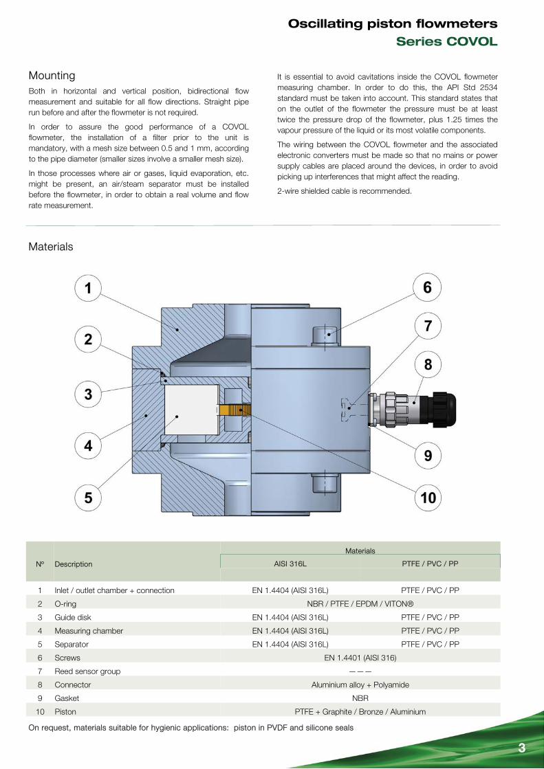
Nº Description
Materials
AISI 316L PTFE / PVC / PP
1 Inlet / outlet chamber + connection EN 1.4404 (AISI 316L) PTFE / PVC / PP
2 O-ring
3 Guide disk EN 1.4404 (AISI 316L) PTFE / PVC / PP
4 Measuring chamber EN 1.4404 (AISI 316L) PTFE / PVC / PP
5 Separator EN 1.4404 (AISI 316L) PTFE / PVC / PP
6 Screws EN 1.4401 (AISI 316)
7 Reed sensor group ———
8 Connector Aluminium alloy + Polyamide
9 Gasket NBR
10 Piston PTFE + Graphite / Bronze / Aluminium
NBR / PTFE / EPDM / VITON®
Materials
On request, materials suitable for hygienic applications: piston in PVDF and silicone seals
3
Oscillating piston flowmeters
Series COVOL
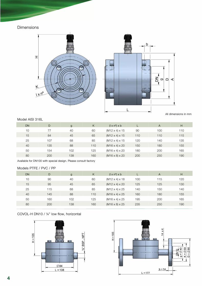
Dimensions
COVOL-H DN10 / ¼” low flow, horizontal
All dimensions in mm
4
DN D g K (l x nº) x b L A H
10 77 40 60 (M12 x 4) x 15 90 100 110
15 84 45 65 (M12 x 4) x 15 110 110 115
25 107 68 85 (M12 x 4) x 15 120 140 135
40 135 88 110 (M16 x 4) x 20 150 180 155
50 154 102 125 (M16 x 4) x 20 180 200 165
80 200 138 160 (M16 x 8) x 20 200 250 190
DN D g K (l x nº) x b L A H
10 90 40 60 (M12 x 4) x 18 100 115 120
15 95 45 65 (M12 x 4) x 20 125 125 130
25 115 68 85 (M12 x 4) x 25 140 150 140
40 145 88 110 (M16 x 4) x 25 160 180 155
50 160 102 125 (M16 x 4) x 25 195 200 165
80 200 138 160 (M16 x 8) x 25 235 250 190
Model AISI 316L
Models PTFE / PVC / PP
Available for DN100 with special design. Please consult factory
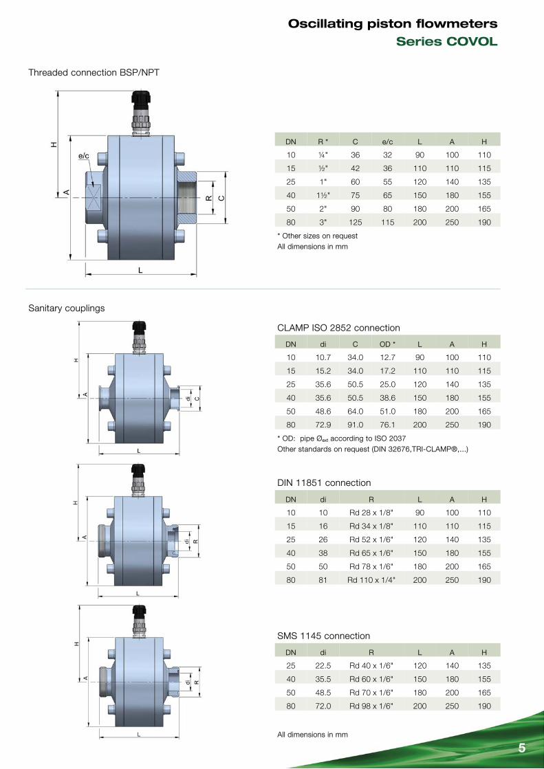
Threaded connection BSP/NPT
Sanitary couplings
* Other sizes on request All dimensions in mm
5
DN R * C e/c L A H
10 ¼" 36 32 90 100 110
15 ½" 42 36 110 110 115
25 1" 60 55 120 140 135
40 1½" 75 65 150 180 155
50 2" 90 80 180 200 165
80 3" 125 115 200 250 190
DN di C OD * L A H
10 10.7 34.0 12.7 90 100 110
15 15.2 34.0 17.2 110 110 115
25 35.6 50.5 25.0 120 140 135
40 35.6 50.5 38.6 150 180 155
50 48.6 64.0 51.0 180 200 165
80 72.9 91.0 76.1 200 250 190
DN di R L A H
10 10 Rd 28 x 1/8" 90 100 110
15 16 Rd 34 x 1/8" 110 110 115
25 26 Rd 52 x 1/6" 120 140 135
40 38 Rd 65 x 1/6" 150 180 155
50 50 Rd 78 x 1/6" 180 200 165
80 81 Rd 110 x 1/4" 200 250 190
DN di R L A H
25 22.5 Rd 40 x 1/6" 120 140 135
40 35.5 Rd 60 x 1/6" 150 180 155
50 48.5 Rd 70 x 1/6" 180 200 165
80 72.0 Rd 98 x 1/6" 200 250 190
All dimensions in mm
DIN 11851 connection
SMS 1145 connection
CLAMP ISO 2852 connection
* OD: pipe Øext according to ISO 2037 Other standards on request (DIN 32676,TRI-CLAMP®,...)
Oscillating piston flowmeters
Series COVOL

The measurement errors can be corrected in the different associated electronic converters by means of the adjustment of the pulse / litre factor, obtaining a maximum accuracy.
A change in viscosity can modify the pulse / litre factor.
In general, a change in density affect the COVOL flowmeters, only at the beginning of the scale:
- If the density value is lower than 1 kg/l, the initial flow rate must be higher so that the flowmeter is sensitive to the liquid flow.
- If the value of density is higher than 1 kg/l, the initial flow rate must be lower so that the flowmeter is sensitive to the liquid flow.
In both cases the changes in flow scales are not significant due to the variation of density (not higher than 5% of the measured value with the reference liquid).
With high viscosities (higher than 1000 mPa·s) the scale ranges might change significantly depending on the liquid viscosity.
DN Flow scales
l/h water
Max. intermittent
l/h water
pulses / litre
approx.
10 / ¼" (H) 25-250 500 100
10 40-350 800 100
15 150-1500 2700 20
25 500-4500 9000 10
40 800-8500 15500 4
50 1500-16000 28000 2
80 3000-28000 50000 1
100 5000-60000 104000 0.2
Flow ranges
The COVOL flowmeters are calibrated with water (density 1 kg/l and viscosity 1 mPa·s). After this calibration the pulse / litre factor is obtained. With this factor, the associated electronic converter can make the calculation of the flow rate and/or the volume values.
As shown in the accuracy curve, the area where the maximum accuracy is obtained is by the mid of the flowmeter flow range.
10 100 1000 10000 100000
l/h H2O ρ=1 kg/l η=1 mPa·s
ΔP
(mH
2O)
3
2.7
1.8
0.9
0.6
0.3
0.2
0.1
DN10H DN10 DN15 DN25 DN40 DN50 DN80 DN100
-1 -0.5 0 +0.5 +1
Flow rate and pressure drop curves
6
Graph 1
Accuracy %
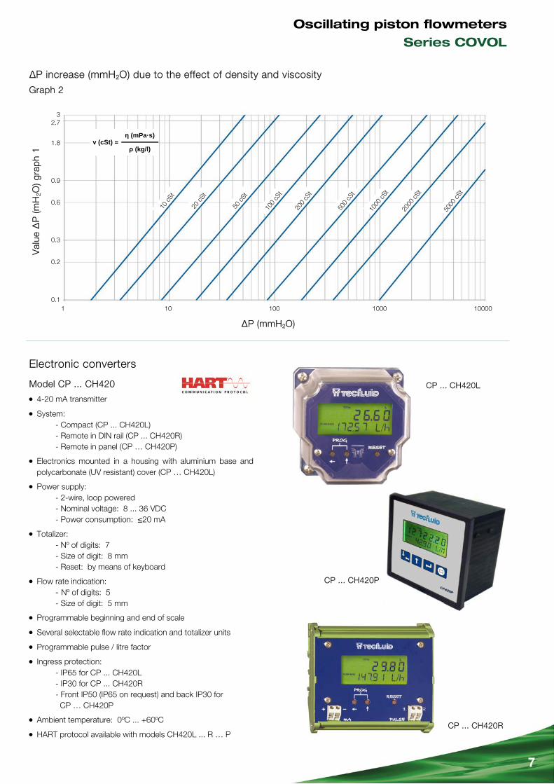
ΔP increase (mmH2O) due to the effect of density and viscosity
Electronic converters
ΔP (mmH2O)
Val
ue Δ
P (m
H2O
) gra
ph
1
CP ... CH420L
CP ... CH420R
η (mPa·s)
ρ (kg/l) ν (cSt) =
1 10 100 1000 10000
2.7 3
1.8
0.9
0.6
0.3
0.2
0.1
7
Graph 2
CP ... CH420P
10 c
St
20 c
St
50 c
St
100
cSt
200
cSt
500
cSt
1000
cSt
2000
cSt
5000
cSt
Model CP ... CH420
4-20 mA transmitter
System: - Compact (CP ... CH420L) - Remote in DIN rail (CP ... CH420R) - Remote in panel (CP … CH420P)
Electronics mounted in a housing with aluminium base and polycarbonate (UV resistant) cover (CP … CH420L)
Power supply: - 2-wire, loop powered - Nominal voltage: 8 ... 36 VDC - Power consumption: ≤20 mA
Totalizer: - Nº of digits: 7 - Size of digit: 8 mm - Reset: by means of keyboard
Flow rate indication: - Nº of digits: 5 - Size of digit: 5 mm
Programmable beginning and end of scale
Several selectable flow rate indication and totalizer units
Programmable pulse / litre factor
Ingress protection: - IP65 for CP ... CH420L - IP30 for CP ... CH420R - Front IP50 (IP65 on request) and back IP30 for CP … CH420P
Ambient temperature: 0ºC ... +60ºC
HART protocol available with models CH420L ... R … P
Oscillating piston flowmeters
Series COVOL
8 HC * : model AISI 316L ; HC ** : models PVC / PTFE / PP
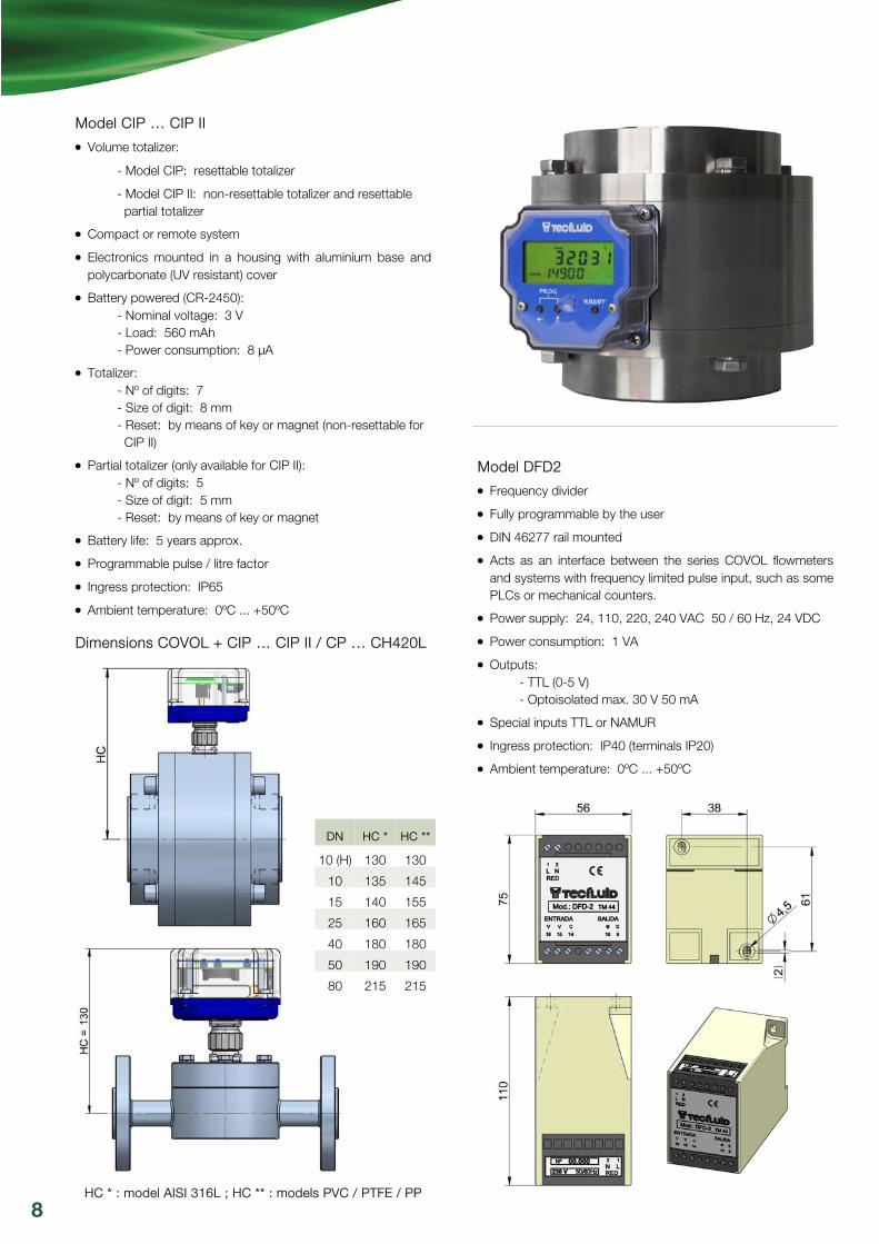
Model CIP … CIP II
Volume totalizer:
- Model CIP: resettable totalizer
- Model CIP II: non-resettable totalizer and resettable partial totalizer
Compact or remote system
Electronics mounted in a housing with aluminium base and polycarbonate (UV resistant) cover
Battery powered (CR-2450): - Nominal voltage: 3 V - Load: 560 mAh - Power consumption: 8 μA
Totalizer: - Nº of digits: 7 - Size of digit: 8 mm - Reset: by means of key or magnet (non-resettable for CIP II)
Partial totalizer (only available for CIP II): - Nº of digits: 5 - Size of digit: 5 mm - Reset: by means of key or magnet
Battery life: 5 years approx.
Programmable pulse / litre factor
Ingress protection: IP65
Ambient temperature: 0ºC ... +50ºC
Dimensions COVOL + CIP … CIP II / CP … CH420L
DN HC * HC **
10 (H) 130 130
10 135 145
15 140 155
25 160 165
40 180 180
50 190 190
80 215 215
Model DFD2
Frequency divider
Fully programmable by the user
DIN 46277 rail mounted
Acts as an interface between the series COVOL flowmeters and systems with frequency limited pulse input, such as some PLCs or mechanical counters.
Power supply: 24, 110, 220, 240 VAC 50 / 60 Hz, 24 VDC
Power consumption: 1 VA
Outputs: - TTL (0-5 V) - Optoisolated max. 30 V 50 mA
Special inputs TTL or NAMUR
Ingress protection: IP40 (terminals IP20)
Ambient temperature: 0ºC ... +50ºC
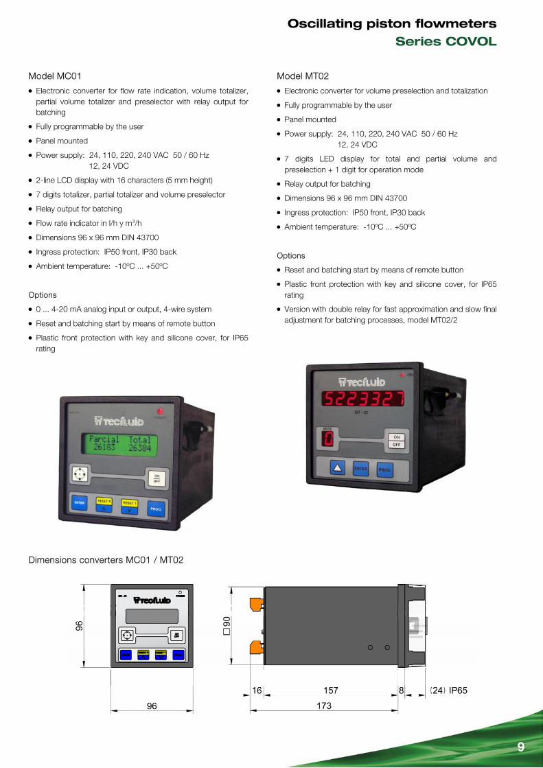
Dimensions converters MC01 / MT02
9
Model MC01
Electronic converter for flow rate indication, volume totalizer, partial volume totalizer and preselector with relay output for batching
Fully programmable by the user
Panel mounted
Power supply: 24, 110, 220, 240 VAC 50 / 60 Hz 12, 24 VDC
2-line LCD display with 16 characters (5 mm height)
7 digits totalizer, partial totalizer and volume preselector
Relay output for batching
Flow rate indicator in l/h y m3/h
Dimensions 96 x 96 mm DIN 43700
Ingress protection: IP50 front, IP30 back
Ambient temperature: -10ºC ... +50ºC
Options
0 ... 4-20 mA analog input or output, 4-wire system
Reset and batching start by means of remote button
Plastic front protection with key and silicone cover, for IP65 rating
Model MT02
Electronic converter for volume preselection and totalization
Fully programmable by the user
Panel mounted
Power supply: 24, 110, 220, 240 VAC 50 / 60 Hz 12, 24 VDC
7 digits LED display for total and partial volume and preselection + 1 digit for operation mode
Relay output for batching
Dimensions 96 x 96 mm DIN 43700
Ingress protection: IP50 front, IP30 back
Ambient temperature: -10ºC ... +50ºC
Options
Reset and batching start by means of remote button
Plastic front protection with key and silicone cover, for IP65 rating
Version with double relay for fast approximation and slow final adjustment for batching processes, model MT02/2
Oscillating piston flowmeters
Series COVOL

10
Exd housing model ADF60V with CIP II display
Exd housing model ADF30
ATEX version The COVOL flowmeter is suitable for its installation in ATEX hazardous area, that is, in those zones where a potentially explosive atmosphere can be generated. There are two types of protection available: Exi intrinsically safe or Exd ExProof.
Exia protection
The reed sensor is considered as “simple apparatus” according to EN 60079-11 standard clause 5.7, since it does not contain its own source of ignition.
Reed sensor technical data:
- Vmax.: 30 V ; Imax.: 20 mA
- Maximum switched power: 0.6 VA
- Max. ambient temperature: 40ºC
According to these data, the flowmeter can be installed in hazardous area when an appropriate zener barrier (please consult) is installed between the hazardous and the safe area. The electronic converters, however, must always be installed in safe area.
Exd protection
These devices conform the 94/9/CE directive (Devices and protection systems for use in potentially explosive atmospheres) as indicated in the CE certificate type LOM 14ATEX and its corresponding marking.
The instrument belongs to group II, therefore it is intended for use in places where there is a risk of generation of an explosive atmosphere, except in mining.
Being category 2GD it can be used in an environment where it is probable to generate an explosive atmosphere due to air and gases mixtures, vapours, mist and dust as well.
Three different types of Exd housings are available:
- Model ADF30: blind housing with reduced dimensions
- Model ADF60V: housing with window, can include the CIP … CIP II or CP ... CH420L converters
- Model ADF60: same as ADF60V but blind housing
Exd version technical data:
- Ambient temperature: -20ºC ... +60ºC
- Electrical wiring inside the Exd housing
- On request ATEX packing glands for standard or shielded cable
- Associated electronics, for models:
- CIP ... CIP II: totalizer battery powered
- CP … CH420: transmitter 2-wire system with flow rate indication, volume totalizer and 4-20 mA output. HART protocol optional
- ATEX certificate Ex d IIC T6 Gb / Ex tb IIIC T85ºC Db
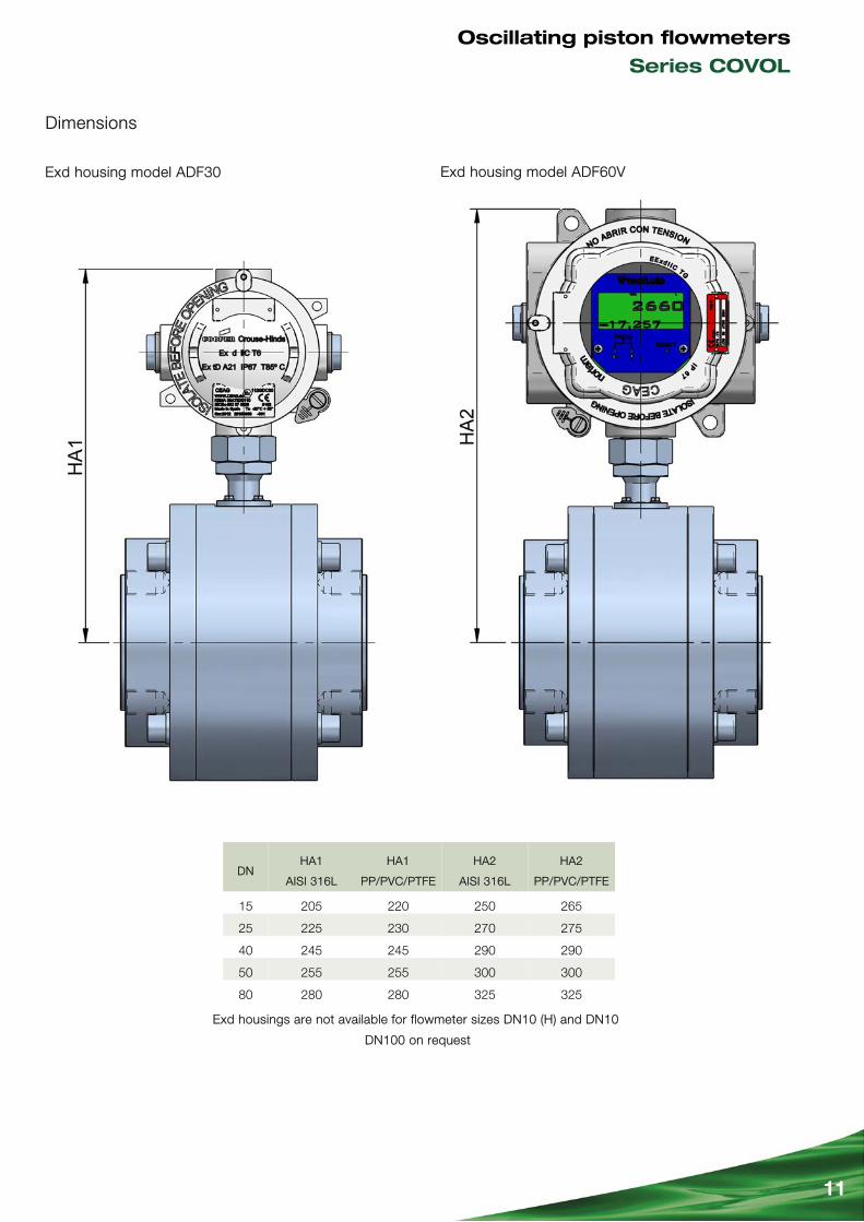
Dimensions
11
DN HA1
AISI 316L
HA1
PP/PVC/PTFE
HA2
AISI 316L
HA2
PP/PVC/PTFE
15 205 220 250 265
25 225 230 270 275
40 245 245 290 290
50 255 255 300 300
80 280 280 325 325
Exd housing model ADF60V Exd housing model ADF30
Exd housings are not available for flowmeter sizes DN10 (H) and DN10
DN100 on request
Oscillating piston flowmeters
Series COVOL

R-C
T-C
OVO
L R
ev. 1
eng
lish
vers
ion
Tecfluid S.A. Narcís Monturiol 33 08960 Sant Just Desvern Barcelona Tel: +34 93 372 45 11 Fax: +34 93 473 44 49 [email protected] www.tecfluid.com
HART® is a registered trademark of HART Communication Foundation
PRESENCE IN MORE THAN 50 COUNTRIES ALL OVER THE WORLD
Quality Management System ISO 9001 certified by
Pressure Equipment Directive 97/23/CE certified by
ATEX European Directive 94/9/CE certified by
The technical data described in this specification sheet is subject to modification without notification if the technical innovations in the manufacturing processes so require. VITON® is a registered trademark of DuPont Dow Elastomers — TRI-CLAMP® is a registered trademark of Alfa Laval Inc.