Embed Size (px)
Citation preview

ORNL/TM- 12715
Chemical Technology Division
Program Management Plan for Development, Demonstration,Testing, and Evaluation Efforts Associated with theOak Ridge Reservation 's Land Disposal Restrictions
Federal Facility Compliance Agreement
T. B. Conley
Date Published: April 1994
NOTICE This document contains information of e preliminary nature.It is sublect to revision or correction end therefore does not represent afinal report.
Prepared byOAK RIDGE NATIONAL LABORATORY
Oak Ridge, Tennessee 37831-6285managed by
MARTIN MARIETTA ENERGY SYSTEMS, INC.for the
MSTERunder contract DE-AC05-84OR21400

CONTENTS
LIST OF FIGURES ................................................. vLIST OF TABLES ................................................ viiEXECUTIVE SUMMARY ........................................... ix
1. INTRODUCTION .............................................. 1
2. SCOPE ...................................................... 32.1 TREATMENT TECHNOLOGIES ADDRESSED ................... 32.2 FINAL WASTE FORMS CONSIDERED ........................ 5
3. OVERALL PLAN STRATEGY ..................................... 7
4. PROGRAM MANAGEMENT ...................................... 94.1 WORK BREAKDOWN STRUCTURE .......................... 94.2 RESPONSIBILITIES ...................................... 94.3 COORDINATION AND REPORTING .......................... 94.4 CONFIGURATION CONTROL ............................... 11
5. DATA EVALUATION ........................................... 135.1 DATA SOURCES ........................................ 135.2 DATA COLLECTION ..................................... 155.3 DATA REVIEW ......................................... 175.4 TREATMENT OPTIONS ................................... 19
6. CHARACTERIZATION PLANS .................................... 216.1 PREPARATION OF SAMPLING AND ANALYSIS PLANS .......... 216.2 DATA ANALYSIS ........................................ 21
6.3 STANDARDS FOR QUALITY ASSURANCE/QUALITY CONTROL ... 21
7. DEVELOPMENT OF TREATMENT TECHNOLOGIES ................... 237.1 TECHNOLOGY DEVELOPMENT ELEMENTS .................. 237.2 MATRIX OF WASTE STREAMS VERSUS TECHNOLOGIES ........ 247.3 THERMAL DESORPTION .................................. 257.4 FINAL WASTE FORMS .................................... 26
7.4.1 Development of Stabilization Technologies ................... 267.4.2 Waste Form Performance Criteria ......................... 287.4.3 Waste Matrix Baseline ................................. 28
7.4.4 Vendor Requirements .................................. 29
iii

CONTENTS (continued)
7.5 TREATMENT PROCESSES FOR AQUEOUS/ORGANICS/DECONTAMINATION ..................................... 29
7.5.1 Aqueous Liquids ..................................... 297.5.2 Organic Liquids ...................................... 317.5.3 Debris ............................................ 32
7.6 TREATABILITY STUDIES APPROACH ........................ 32
8. PILOT-SCALE DEMONSTRATION FACILITIES ....................... 358.1 RATIONALE ........................................... 358.2 DEMONSTRATION MANAGEMENT .......................... 36
9. PROCESS ANALYSES .......................................... 37
10. PERMITS .................................................... 3910.1 COORDINATION AMONG ACTIVITIES AND WITHIN THE SITES ... 3910.2 OVERALL PERMI'VHNG STRATEGY ......................... 3910.3 ASSESSMENT OF OFF-SITE FACILITIES' PERMITS .............. 40
11. QUALITY ASSURANCE/QUALITY CONTROL ........................ 41
12. INTERACTIONS WITH THE NATIONAL LOW-LEVEL MIXEDWASTE PROGRAM ............................................ 43
13. SCHEDULES AND COSTS ....................................... 4713.1 THERMAL DESORPTION ASSUMPTIONS ..................... 4713.2 FINAL WASTE FORMS ASSUMPTIONS ....................... 50
13.3 AQUEOUSORGANICS/DECONTAMINATION TECHNOLOGYDEVELOPMENT ASSUMI:q'IONS ............................ 51
13.4 DATA INVESTIGATION ASSUMPTIONS ...................... 5113.5 OTHER ASSUMPTIONS ................................... 51
REFERENCES ..................................................... 53
APPENDIX A. DATA SUMMARY ...................................... 55
APPENDIX B. MIXED WASTE FEED STREAM DATA FOR MWTF ............. 67
APPENDIX C. SUMMARY OF PREVIOUS TREATABILITY STUDIES ........... 75
iv

LIST OF FIGURES
1. DOE National Plan mixed waste classification system ...................... 2
2. Organization chart .............................................. 10
3. Waste evaluation methodology ..................................... 14
4. Surrogate waste streams for MWIP .................................. 44
5. FFCA treatability study/technology development schedule .................. 49

LIST OF TABLES
I. Treatment technologies selected for treatability studiesand monitoring ................................................. 4
2. Typical DOE facility files ......................................... 16
3. Waste characterization sufficiency criteria .............................. 18
4. Wastes not currently scheduled for treatment in the MWTF ................. 25
5. Chemical/physical separation technologies ............................. 30
6. DDT&E budget requirements ...................................... 48
vii

EXECUTIVE SUMMARY
On June 12, 1992, the U.S. Department of Energy (DOE) Oak Ridge Operations Officeand the U.S. Environmental Protection Agency (EPA)-Region IV signed a Federal FacilityCompliance Agreement (FFCA) to regulate the treatment of wastes govemed by the LandDisposal Restrictions (LDR) of the Resource Conservation and Recovery Act. ComplianceRequirement 5 of the agreement states that "... DOE shall submit to EPA for review andapproval a plan for the treatment of the LDR prohibited wastes identified in Appendices 1B,2B, and 3B. This plan must identify the treatment stiategy for such wastes to meet LDRtreatment standards and must include a schedule, not to exceed two (2) years after thesubmittal of this plan (i.e., March 1995), for the evaluation and prioritization of treatmentmethod options, treatability studies, if required, and technology developmenL" The FFCAdivided the mixed wastes currently stored on the Oak Ridge Reservation (ORR) into twocategories. Appendix A listed those wastes for which existing treatment methods and facilitiesexist. Appendix B listed wastes for which no identified treatment methods or facilities existon the ORR.
As part of the FFCA, DOE was required to submit to EPA a plan that documents thestrategies that will be used to treat Appendix B wastes generated and/or stored on the ORR.These strategies considered the evaluation, selection, and prioritization of treatmenttechnologies and the identification and performance of treatability studies and technologydevelopment activities necessary to comply with the applicable regulatory standards. TheStrategic Plan for the Treatment of Appendix B Wastes was issued on February 12, 1993.
Development efforts will be coordinated with the FFCA programs at the PaducahGaseous Diffusion Plant (PGDP) and the Portsmouth Gaseous Diffusion Plant (PORTS). Thelow-level mixed wastes currently stored at PGDP and PORTS are similar to those on the ORR.
When waste types permit similar treatment, the PGDP and PORTS wastes will be integratedinto the ORR process development efforts.
This program management plan covers the development, demonstration, testing, andevaluation efforts necessary to identify treatment methods for all the waste listed in
Appendix B of the ORR's LDR/FFCA as well as any new wastes which meet Appendix Bcriteria. To successfully identify a treatment method, at least a proof-of-principle level ofunderstanding must be obtained: that is, the candidate processes must be demonstrated aseffective in treating the wastes to the LDR; however, an optimized process is not required.Where applicable and deemed necessary and where the budgets will support them, pilot-scaledemonstrations will be pursued.
The overall strategy being adopted in this program will be composed of the followingactivities:
1. scoping of the study,2. characterization,
3. development and screening of alternatives,4. treatability investigations, and
5. detailed analysis of alternatives.
The strategic plan is the basis for the efforts described in this plan.
ix
itI

1. INTRODUCTION
i
On June 12, 1992, the U.S. Department of Energy Oak Ridge Operations Office(DOE-ORO) and the U.S. Environmental Protection Agency (EPA)-Region IV signed a
Federal Facility Compliance Agreement (FFCA) to regulate the treatment of wastes governedby the Land Disposal Restrictions (LDR) of the Resource Conservation and Recovery Act(RCRA). Compliance Requirement 5 of the agreement states that "... DOE shall submit toEPA for review and approval a plan for the treatment of the LDR prohibited wastes identifiedin Appendices 1B, 2B, and 3B. This plan must identify the treatment strategy for such wastesto meet LDR treatment standards and must include a schedule, not to exceed two (2) years
after the submittal of this plan (i.e., March 1995), for the evaluation and prioritization oftreatment method options, treatability studies, if required, and technology development. ''_ TheFFCA divided the mixed wastes currently stored on the Oak Ridge Reservation (ORR) intotwo categories. Appendix A listed those wastes for which existing treatment methods andfacilities exist. Appendix B listed wastes for which no identified treatment methods orfacilities exist on the ORR.
As part of the FFCA, DOE was required to submit to EPA a plan that documents thestrategies to determine which technologies will be used to treat Appendix B wastes generatedand/or stored on the ORR. These strategies considered the evaluation, selection, andprioritization of treatment technologies and the identification and performance of treatabilitystudies and technology development activities necessary to comply with the applicableregulatory standards. The Strategic Plan for the Treatment of Appendix B Wastes (TSP) wasissued on February 12, 1993.2
Development efforts will be coordinated with the FFCA programs at the PaducahGaseous Diffusion Plant (PGDP) and the Portsmouth Gaseous Diffusion Plant (PORTS). Thelow-level mixed wastes currently stored at PGDP and PORTS are similar to those on the ORR.When waste types permit similar treatment, the PGDP and PORTS wastes will be integratedinto the ORR process development efforts.
The TSP arranged the Appendix B wastes into categories and subcategories defined byDOE's Mixed Waste Treatment Project (MWTP). These groupings consist of 9 major wastecategories and 92 subcategories. Figure 1 represents the MWTP waste grouping hierarchy.
The Appendix B wastes were grouped into seven of the nine major waste categories.Categories 8000 (Unknown) and 9000 (Treated Wastes) were not required. Waste data by siteas well as summary data for the entire ORR can be found in Appendix A of this report.
The treatment strategies formulated in the TSP reflect DOE's preferred options fortreating the Appendix B wastes. The TSP emphasizes four areas: pretreatment to allow eitheron-site or off-site treatment, development of technologies that are well defined or underdevelopment for similar waste types, integration of technologies under development at otherDOE facilities to treat ORR wastes, and continued shipment of "No Radioactivity Added"wastes by modifying existing on-site facilities combined with establishment of procedures toensure that potentially radioactively contaminated materials are not inadvertently released.Sixteen National Plan subcategories were combined to form 11 treatability groups. Thesetreatability groups were distributed among 11 treatment technologies: 4 chemical processes,
5 thermal processes, and 2 immobilization processes.

ORHLDWG|4A-108
I MixedWastes I
I I I I I I I I I
,oooi.ooi' _ooo,_.ooJlw._..._°°°il _.._°°°i ..z._.._°°°_.oooJi.._'°°°Aqueous Organic ISolld Process I Soils Debris Special Inherently Unknown TreatedLiquids and I lquldl I Residues J
Slurries Wastes
,oo'L.,oo 4,ooh ,oolh.,oo lh,.oo,,Acidic Aqueous/ Inorganic Organic Metals Lab Packs Liquid Unknown Cement,, Organic Matrtx Solids Contaminated Debris , Mercury liquids I! I
! 200 Liquids Soils 6200 i | 9200
Basic , I 2200 Organic 4200 Inorganic Metals 1Lead Shapes Unknown1300 | Pure Organic Matrix Solids Inorganic Non-Metal | Solids 9300
Neutral I Uqulds Debris 4 6300 7300 ! Metal
1400 "|' 2900 Soils II 5300 i ' Explosives Beryllium 8900 _I Ji, _w°'"I °""' "°°1Cyanide [JUncategorized 4300 H Combustible I 6400 Unknown _ Polymer
-] Organic Organic & Debris J Compressed 7400
1900 I Uqulds Inorganic Gases & Batteries 9900Uncategorlzed Contaminated II 5400 i Aerosol Cans Other Forms
Aqueous Soils L._leterogeneous_
I Oeb,,II 65ooLlquld 4400 ' Honford
Soils wlth Double ShellOrganic TanksDebris
4500Soils wlthInorganic
Debris
4600Soils with
Organic andInorganic
DebHs
4900Uncategorized
Soils
Fig. 1. DOE National Plan mixed waste classification system.

2. SCOPE
This program management plan covers the development, demonstration, testing, andevaluation (DDT&E) efforts necessary to confirm treatment methods identified in the strategicplan for the wastes. To successfully confirm a treatment method, at least a proof-of-principlelevel of understanding must be obtained: that is, the candidate processes must be shown to beeffective in treating the wastes to the LDR; however, an optimized process is not required. Asresources become available, pilot-scale demonstrations will be pursued.
At the present time, only one low-level mixed waste disposal option has a significantprobability of being viable in the near future. That option is shipment to Envirocare.Envirocare, located near Clive, Utah, is the first and only commercial mixed waste disposalfacility. The process is under way to establish Envirocare's availability for the disposal ofDOE mixed waste. Envirocare's waste acceptance criteria (WAC) are to meet the LDRrequirements and its own concentration limits on several radionuclides. Since all the treatmenttechnologies already have the LDR requirements as their performance basis, no problems areanticipated meeting that portion of the WAC. Based on the current understanding of theradionuclide content of the ORR wastes, 90 to 95% of the wastes will meet the Envirocare
WAC. For those wastes that do not, treatment processes must be developed when resourcesbecome available. Martin Marietta Energy Systems, Inc. (MMES), does not want to store thewastes indefinitely and, therefore, should keep disposal requirements in the plans.
The DDT&E efforts support the basic development needs of the Mixed Waste TreatmentFacility (MWTF) but do not attempt to validate a specific design or process associated withthis facility.
In addition, the efforts occurring on the ORR will be coordinated, as practicable, withthe FFCA program at PGDP as well as at PORTS. The low-level mixed wastes at PGDP andPORTS are, in many ways, similar to those in Oak Ridge. When the similarities permitsimilar treatment, the PGDP and PORTS wastes will be accounted for in the ORR processdevelopment.
2.1 TREATMENT TECHNOLOGIES ADDRESSED
A wide range of possible candidate treatment technologies exists. These technologiesare at various stages of development from conceptual design to commercial-scale facilities.Some of these technologies have been used to treat low-level mixed waste, but a majority havenot. The strategic plan was developed by Energy Systems Waste Management Organization(ESWMO) to place the Appendix B wastes into categories as defined by the DOE low-levelmixed waste project (funded by EM-30) and to identify all appropriate treatment technologiesfor each of those categories. A prioritization analysis was performed to match the categorizedwastes with a preferred treatment technology or technologies. (see Table 1). The resultingmatrix is the planning foundation for the DDT&E Program. Additional explanation of thistable can be found in Section 5.1. Sixteen National Plan subcategories were combined to form11 treatability groups. These treatability groups were distributed among 11 treatmenttechnologies: 4 chemical processes, 5 thermal processes, and 2 immobilization processes. Thetwo immobilization processes and two of the thermal processes (glass and microwave melting)are addressed as part of the Final Waste Forms (FWF) Project. Only one of the thermalprocesses, low-temperature thermal desorption, will be pursued vigorously on the ORR.


Thermal desorption is a mature, well-understood process which has the potential for treatingthe largest waste streams with a reasonably straightforward approach and thus will beemphasized in the DDT&E Program.
2.2 FINAL WASTE FORMS CONSIDERED
No single f'mal waste form is applicable to all wastes due to either their matrix or theircontaminants. The strategic plan identified four types of final waste forms that might beapplicable to the Appendix B wastes: glass, ceramic, cementitious, and polymer encapsulation.The FWF Project will establish the framework by which each Appendix B waste can bematched to a waste fona. The development work will consider several general criteria besidesLDR considerations for final selection of a waste form. These other criteria are expediency(both schedule and cost) and how effectively the waste form meets the performance criteria
[e.g., WAC, U.S. Nuclear Regulatory Commission (NRC) requirements]. The choices, bywaste stream, will be based on a set of proof-of-principle studies that will be defined in theFWF Project plan.
The question of the "best" final waste form for low-level mixed wastes has consumed agreat deal of time and effort throughout the DOE complex. The National Low-level MixedWaste Program (NLLMWP) and its technical arm, the Mixed Waste Integrated Program(MWIP), which is funded by EM-50, are aggressively pursuing vitrification as their enhancedwaste form of choice. There are several advantages to glass or ceramic waste forms, theprimary one being volume reduction of the individual waste. Because significant resourceswill be required to develop these more advanced technologies and current mixed wastedisposal options require only "stabilized" waste forms meeting Toxicity CharacteristicLeaching Procedure (TCLP) standards, the early emphasis of the FWF Project will be toconcentrate on conventional, cementitious waste forms. Other waste forms will be explored asalternatives to the grout-based approach.

3. OVERALL PLAN STRATEGY
The overall strategybeing adoptedin this programconsists of the following activities:
1. scoping of the program,2. characterization,3. development and screening of alternatives,4. treatability investigations, and5. detailed analysis of alternatives.
Scoping is the initial planning phase, and most of the steps undertaken during scopingcontinue and are refined (and often revised) in the later phases. Typically, the first activity inthe seoping is collection of existing data. Based on this information, the study boundaries areset, the objectives are identified, and the likely actions are defined. All of these activities havebeen performed and are documented in the strategic plan. Therefore, this plan will use thatdocument for the scoping of the DDT&E Program.
An evaluation of existing Appendix B waste information will be conducted as the firststep in the characterization effort. Each waste record will be reviewed to determine ifsufficient compositional information is available to proceed with treatability studies. Wastegenerator interviews will also be conducted to gather additional information. Those wastes forwhich insufficient information can be obtained by this method will be submitted forcharacterization sampling and analysis.
Characterization is needed to establish the physical and chemical characteristics forthose wastes that lack previous analytical data or sufficient process knowledge. This activitywill occur in parallel with most of the waste stream identification effort. Characterization isnormally scheduled so that the results of the initial sampling efforts can be used to refine theplans developed during scoping to better focus subsequent efforts.
The preliminary characterization of some ORR waste streams has been accomplished.However, waste stream characterization will be a integral part of this plan and will requireconsiderable resources to accomplish. Section 6 of this plan outlines the evaluation of the
i existing data, while Section 7 discusses characterization. In all likelihood, a substantial portionI of this work will have to be subcontracted to qualified vendors when MMES resources cannot
support the schedule. These vendors will include both EPA Contract Laboratory Program(CLP) laboratories and personnel to actually take the samples in the field (for characterization)and experienced subcontractors to evaluate the available waste data.
The next phase of the program, which is development and screening of alternatives,requires the following:
1. identifying treatment obiectives;2. identifying potential treatment processes that will satisfy these objectives;3. screening the technologies based on effectiveness, implementability, and cost; and4. assembling technologies and their disposal requirements into alternatives.
The strategic plan contains the preliminary criteria and will form the basis for the screening oftechnologies described in this plan.
q I!

8
The treatability investigations and the detailed analysis of alternatives form the purposeand objective of this program plan. Treatability investigations or studies are conducted toprovide sufficient data to allow treatment alternatives to be evaluated as well as to reduceperformance uncertainties for those methods chosen to treat the waste or remediate the site.The decision process for treatability investigations consists of these steps:
1. determining the data needs;2. reviewing the existing data and available literature on the technologies to determine
if existing data are sufficient to evaluate alternatives;3. ly._rform.Angtreatability tests (bench and pilot scale), as appropriate, to determine
performance, operating parameters, and relative costs of potential technologies;4. evaluating the data to ensure that the data quality objectives (DQOs) are met; and5. selecting technology for waste streams.
The data needs for the candidate technologies/processes will be provided by projectteams focused on the major areas (see Section 5). This information will be vital to theevaluation activities outlined in Section 6. The number and kind of treatabili_, studies will bean outgrowth of the efforts of the teams reviewing the technology areas and the waste dataevaluation team.
As described in later sections of this plan, for numerous wastes streams, a determinationmust be made on how they will be treated. However, limited analytical data are available, andmany of the proposed treatment technologies have had limited or no application in thetreatment of mixed waste. The lack of characterization data and experience doe_ not changethe schedule that DOE and MMES must follow. Therefore, simply stated, this program willimplement the detailed strategies outlined in the following sections only if sufficient resourcesare made available in a timely fashion.

4. PROGRAM MANAGEMENT
Effective program management is crucial to the successful implementation of this planand thus to meeting the requirements placed on MMES by DOE. The DDT&E Program relieson the contributions of many organizational units within MMES for its success. These includeESWMO, MMES Engineering, the Chemical Technology Division, the Oak Ridge Y-12 PlantDevelopment Division, the Waste Management divisions of all three plants, and Procurement(see Fig. 2 for organization chart). Not ordy is the organization large, but the schedule is tightand has a limited budget. Therefore, program management needs to be flexible and adaptableto meet the challenges put before it. The following sections briefly address the managementtools to be utilized.
4.1 WORK BREAKDOWN STRUCTURE
A work breakdown structure (WBS) is being developed and will be utilized as the basisfor the following:
1. uniform project planning and visibility,2. assignment of responsibilities,
3. identification of end item objectives for monitoring and progress,4. network scheduling and budgeting, and5. ensuring interfaces among the various organizations.
4.2 RESPONSIBILITIES
As stated previously, one of the functions of the WBS is to assign responsibility for thediscrete deliverables found in the lowest tier of each leg in the WBS. To accomplish this goal,a responsibility matrix will be generated. On one axis the deliverables will be listed, while thepersons and organizations that are involved with the FFCA will be listed on the other axis. At
each intersection of deliverable and responsible person or organization, a code will be placed.This code will designate what level or type of responsibility the designated person will havefor the deliverable. If the block is left blank, no responsibility is conferred. To ensure that all
;_ interested parties are involved with the formulation of this matrix, blank copies will becirculated to those involved at DOE, ESWMO, Engineering, ORNL, the Y-12 Plant, the
Oak Ridge K-25 Site, etc., to solicit each party's perspectives. The responses will be compliedinto a summary chart that will be used in working sessions to resolve any differences. Thematrix will be published as a separate document since it may undergo several revisions beforeit can be considered final.
4.3 COORDINATION AND REPORTING
Due to the complexity of this program, coordination of all the individual efforts will becritical for it to succeed. To effect and maintain this coordination, regularly scheduled
meetings will be held. This will include weekly meetings of the leaders of the major efforts

ORHLDWGII]A-410R4
FTCA APP[NDIXB WASTI[S
T. J. AIP.AH_ !D. A. HUTCHIHS!D. P. SCHAEFFTRKOEI"_R!
i ........ "1
I 1TCHNOLOGYD[YELOPId[HT, [SWkIOQA SPECIAliST
DEMm4SllMTIOH,1TSllNG, R. GILR[ATHAHD EVALUATION T.F.. IdeDOWELL
1'. I. CONLEY1_4,COOROIHATOR
i! ! I I I
I KEY INTERFACES 11iERMALD[SOaPTiON AQUEOIJIS/OIlCJUHICS,/_[CON DATAINVESTIGATION DI[IdONSTRATION$ STAFF"SUPPORT
DLrV[LOPHI[NT TECHHOtOGYOk'YIU.OPHI[NT COORDIHATOR
O. K. UTTLEs,'4 1". L. DOHN.DSON= 1'. IL COHLEY_ Id. L IdORRIS:r''4m,mm._
LJ It. IL _| N.H. _S P.H. I_CI(US2,4 it. O. P'k't'E.laSk"l_ S.l 11'.O. ROGERS! M. IL I_ Mli EET ¢_11ON O.K. UTTLE"%4 L. 11tAMId[1.L.G/C
_J. w. SmDF.R2 T. HJGO0_,G/c
11t_ltlF.NT V.P. GIt,._ s COOROIHAI'IOH QA/QC. L. IL S111tTON C.M. C[CALA'1; T.N. 1'[1_ I 1"... GILLIAId2"4 W.S. MeOARVi[Y.ASO
FINALWAST[ FORMS 2. _ T_'CHHOLOGYDIVISION/ORNLT. hi. GIU.INd2-4 3. D[VI[LOPMD4T_/OAK RID(;[ Y-12 PLANT U.D. ORIFFITHe4. DUN. CAPACITY
A. BLF..I_z 8. ANN.YTICAL_ (N_,_i,HI_TIOHC. L. _z I. INFORMATIONMANAO(_NT SZlWlCl[S,k. H. GOItlHsc. H. MATTUSz A..qG:AUTOM.t11_SCI[NCt'S OROUP.inc.R. D. SP[NC[2 GCW:_/COMIdONWIMLTH _ AND CONSULTAH13
MTI=MIDWI[_rTI[CHNICALINSTnIJI_
Fig. 2. Organization chart.

11
and biweekly meetings of the project teams. These meetings of the project teams are designedto maintain the exchange of information at the working level among the various groups. Inaddition, monthly reports will be issued (either by electronic mail or by hard copy) as well asquarterly reports. The monthly reports will be targeted to MMES personnel involved with orinterested in the LDR/FFCA efforts. The quarterly reports will have DOE and EPA as theirtarget audience.
4.4 CONFIGURATION CONTROL
With a program as large and complex as this one, many different documents will begenerated to communicate the program's needs and progress. These documents will haveseveral different authors and thus be published at several different locations. To maintainconfiguration control of the baseline program definition, the official record copy of each of theprimary documents will be kept in a central location. This location will be the office of theDDT&E coordinator at ORNL.The documents that require configuration control include thefollowing:
1. program management plan;2. quality assurance plans (for the program and each ot the major projects);3. responsibility matrix;
4. project plans for Thermal Desorption, FWF; Radionuclide Removal, SurfaceDecontamination, and Liquids Treatment (aqueous and organic);
5. test plans; and6. statements of work for vendors.
The MMES-established quality assurance (QA) requirements will be adhered to fordocument control and archiving.

5. DATA EVALUATION
The development of a successful treatment technology requires input and planning frommany sources. At a minimum, the following information must be collected, compiled, ordeveloped:
1. adequate information about the waste stream(s) to be treated,2. a clear understanding of the capabilities or projected capabilities of the candidate
technologies which are proposed for treating the wastes,3. a list of information that is lacking from items 1 and 2 above that is required to
perform treatability studies using the candidate treatment technologies,4. a definitive set of performance criteria for the treated wastes, and5. a detailed plan for closing the information gaps that prevent implementation of the
chosen technologies.
Items 1 through 3 will be addressed in this section of the plan. The last two items inthe preceding list will be addressed in Section 7 by general technology area.
The strategic plan requires that an evaluation of all LDR wastes be made. The goal ofthis effort is to establish the information to effectively conduct treatability studies andtechnology development for mixed waste treatment. The Evaluation of Waste Data project hasthe following four objectives:
• develop technology-based information standards that are required to adequatelyperform treatability studies on specific waste types;
• gather and evaluate waste information by reviewing existing waste databases anddocumentation and by conducting generator interviews, as necessary, to categorizewastes into National Plan categories (NPCs) and treatability study groups (TSGs);
• place wastes that share host matrix properties into treatability study populations; and• establish pretreatment, primary treatment, and posttreatment requirements for all
Appendix B waste.
The satisfactory accomplishment of these objectives will optimize the characterizationefforts and minimize the number of treatability studies required to develop treatmenttechnologies for Appendix B mixed wastes. In addition, this evaluation may identify potentialdeficiencies with previous RCRA characterizations. The data evaluation methodology ispresented in Fig. 3.
5.1 DATA SOURCES
The primary sources of data conceming these wastes are the waste generators and thosepersons who have been tasked to store the wastes• The waste records were generated in aneffort to comply with EPA and DOE requirements (mostly cataloging requirements). As such,they often do not provide sufficient information on which to base sound judgments as to theappropriate technology or technologies that could be applied to waste treatment. In addition tothese waste records, several other data sources will be analyzed for possible use. Thesesources include, but are not limited to, project-specific databases, Material Safety Data Sheets,
13

illll
fiii!ill 1:.::;_i_!:_!!i_:!!i;:i:_ii!_i_;:iii_i;:.i_i`_:_i!i_i_i_:i_i_iiii_i_ii_i_;!_i:i:i! AssignNPC I AssignTSGi_i_!iiiili_! _,- basedon waste ..... _"-- basedon NPCl_:it!!!ill:!i!i!_ii:i_!_iii_!!ii_,!!_i!!!_i_i;ii_:ii_:_i_,:.i_iz,ii._;ii_i_!:_i_:._ili matdx & c,ontaminants andwaste properties
! N°Create Populations ,_1of SimilarWastes
Yes
I Statistically Select _ Yes
ContainersforSampling
1 .oN° _ sample All Containersin Initiate S&APopulation _;_: WorkAuthorization/
-Technology Development Info Standard- KnownReadiness Review Requirements
_ . .. _,_. - MWTF Coordinator Input- Preliminary H&S Checklist
Fig. 3. Waste evaluation methodology. NPC = National Plan category;TSG = treatability studygroup;S&A = samplingandanalysis;MWTF = Mixed WasteTreaUnentFacility; H&S = health andsafety.

15
Request for Disposal (RFD) documentation, and process and/orbuilding documentation. Theevaluation of historical information has been completed or is currently being conducted atother DOE sites. The types of information being utilized in these efforts are presented inTable 2. The data quality of these miscellaneous sources will be closely scrutinized to ensurethat the information is valid and meaningful.
If the preceding sources of data prove to be inadequate to meet our goal, the generators'process knowledge may be used to obtain the required information. Although processknowledge cannot guarantee what contaminants are in rite wastes or the levels of thesecontami_ants, it can provide a set of principles to use to reduce the scope of characterizationrequired. For example, if process knowledge confirms that a particular waste has never beenin a radiological area, then the characterization can focus on the RCRA aspects alone.Acquiring this process knowledge will prove invaluable in obtaining the information necessaryto accelerate Oak Ridge's compliance efforts.
Process knowledge may not be necessary where actual and meaningful characterizationhas been performed. However, wastes with adequate characterization may be a small subset ofthe total inventory. An effort is in progress by the individual sites to augment the existingwaste records with more complete data. The data evaluation group will work closely withthose involved with the characterization through the program's sampling and analysiscoordinator.
A further source of information is the studies that have been performed prior to this one.Researchers who have prepared studies evaluating alternatives and prioritizing waste streamsand treatment technologies3 have searched for available data to use in their deliberations. Suchsources of information will be thoroughly sought out and utilized.
5.2 DATA COLLECTION
Unique databases containing a varietyof waste information are maintained by each ORRfacility. Each database contains several thousands of waste records, which are comprised ofmultiple data fields including, but not limited to, waste description, mass, EPA code, andcontainer identification. Each waste record has been or will be assigned to an MWIP NPCaccording to the combination of its contaminant and matrix composition.
The primary sources of waste record information are the waste generators and facilitypersonnel associated with ORR treatment and storage facilities. Waste records have beencompiled over a period of several years to comply with EPA and DOE requirements. Theserecords do not necessarily provide sufficient information to conduct treatment technologydevelopment. Other sources of waste information may include project-specific databases,Material Safety Data Sheets, RFDs, process documentation, and previously performed studies.The data quality of these sources will be closely scrutinized to ensure the information theyprovide is valid and meaningful.
A container survey is currently being conducted at the K-25 Site to verify drum contentsand labeling. A similar survey has been conducted at ORNL. These results are currentlybeing verified and refined. As each facility augments existing waste records, refined data willbe incorporated into the waste evaluation process to ensure the use of the most current andreliable characterization data available.

16
Table 2. Typical DOE facility files,, , ,, , ,' ' " , ,,,, ',', ' , '""" , , i " ," ' ', "', '
Off-site files
On-site files (unclassified only)
Classified files in vault storage Personnel f'tles for previous employees
Unclassified files Health files (including x-ray records) forprevious employees
Enginee.dn.g project files Engineering drawing files
Engineering drawing files Engineering project files
Correspondence fries AEC/ERDA/DOE records (filed according 'to the AEC friing system)"
Waste management files AEC/ERDAJDOE guidance and orders °
Weapons files Air monitoring and sampling fries
Waste shipment files Dosimetry records
Analytical reports for both production Special project filesand environmental activities
Micmfrimed files Federal, state, and local standards
Legal files Guidance and nationally recognizedstandards (such as National Bureau ofStandards Handbook 52)
Incident and property loss files Radiation contamination incident files
Radiation contamination incident files Personal fries from previous employees
Purchasing files
Photography files
Property utilization and disposal files
Special project files
Personal fries from previousemployees
: ' t,,, , , "
"AEC=U.S. AtomicEnergyCommission;ERDA=U.S.EnergyResearchandDevelopmentAdministration;DOE= U.S.Departmentof Energy.
Source: BarbaraA. Swensen,FrankJ. Blaha,andAnnK.Sieben,"Valueof HistoricalRecordsandCorporateMemoryinEnvironmentalRestorationWorkatDOEFacilities,"presentedat WasteManagement'93: TechnologyandProgramsforRadioactiveWasteManagementandEnvironmentalRestoration,February28-March4, 1993.
17
$.3 DATA REVIEW
Existing electronic databases of stored wastes from each of the three ORR plants will bescreened to establish a list of wastes without identified existing treatments. This screeningmay involve removal of all nonhazardous wastes and all wastes destined for existing treatmentfacilities on the ORR. Wastes without identified existing treatment which are stored on theORR but are not recorded electronically will also be incorporated into the electronic database.Information such as container numbers, waste descriptions, EPA codes, mass, physical state,storage location, storage date, and radiological determinations will be available. Using thesedata, an NPC and a TSG will be assigned. Additional information required to assign NPCsand TSGs will be collected from document reviews and, if necessary, from generatorinterviews. After individual records are fully evaluated, information will be entered into aninterim database and tracking system. The evaluated waste data can be interfaced withexisting electronic files or future waste information systems.
After waste records have been assigned to a TSG, sorted, and subjected to documentreview, the database and tracking system will be ulxlated to include this information. Amethodology to evaluate this base information will be developed and may include furthercategorization of wastes within or across TSGs. Selecting waste groups for technologydevelopment and treatability study testing will include grouping wastes with like NPCs withina TSG. Further grouping as a treatability population will be made based on analytical orqualitative information concerning the waste matrix; a minimum waste quantity will beestablished to eliminate as candidates those wastes that cannot be sampled. Container numbersfor each RFD within a population will be subjected to statistical analysis and samples fromselected drums composited for treatability studies. Additional selection guidelines may berequired, and a formal selection methodology will be prepared.
Performing treatability studies on representative san_plesfrom these groups rather thanon individual wastes will minimize the amount of characterization and the number oftreatability studies required, while providing the necessary engineering data to proceed withdemonstration- and production-scale efforts. TSGs will combine wastes that have similarmatrices and contaminants with respect to potential treatment. These groups will berepresentative of the range of host matrices and contaminants contained in an NPC. Criteriawill be refined to ensure that wastes are combined in a way which will enhance theperformance of the treatment options considered (e.g., assay blending).
Information standards are required as part of the characterization project. Theinformation standard(s) will establish the analytes required to fully characterize the waste toeffectively conduct treatability studies. The information needs depend on the specifictechnology selected for each waste type. Development of the information standards willinclude literature review, input from technology vendors, subject matter experts within andoutside the DOE complex, MMES's technology development, and the MWTF personnel.
Even though it is recognized that most of the Appendix B wastes located on the ORRrequire technology development so that capable production treatment processes can beestablished, the resources to achieve this goal are limited. Prioritization of TSGs fortechnology development will be based primarilyon waste quantity but will consider otherfactors as appropriate.

I _ ii [ 1" | I I I I _II| Ill I Il
Table :3. Waste characterization sufliciency criteria
Oql| IiquN Aqu_ Ikpdd "rl_nnlC_w_lco'l_tl_ parameter trmUmm¢ trmtmmt" _ Immebilhud_' ,lecNcMJ,mm_"
m,,u,==a_i,_ ,_,=_d x X x X xHoa mmu .merm compo_m X X X X X
RCRA om_ concentrations ' X X X X" X
PCBs X X x ' ' X X
Dissolvedsolidsspeciesandconcentrations X X X",,
Suspended solids concemmion X X X'
Cornpltxingand chelatingagemtspresent X X
Moimaz concenttatice X X X X, ,,,
Htlides and nitrate concentmiom X,,,,
Sulfur and phosphorus compoundconcentnaions X
Totalorganic caCoon(TOe) concentration X X X,,,
Oil and gw.ase content _...- X X X X,, _-_'_,;,,,
-Bulk combustiblescontent _ X* X* X* X"./^:..- • ,=
Particle sizefractions X X
Metal pieces cmttent X' 'X_ X* oo
Bulkphysical shapeandsize X* X'_ X', ,,
Surface characteristics(clean, painted,oily, cracked,ec.) X*' X"
"AqueousliquidtreatmenttechnologiesincludeIx_ipilmtion.ionexchange,chelation.['titration.cL,rbonadso_ion,andchemicalqmmobilization technologies include cementation,glass vitrification,polymer encapsulation,and microwavesolidification."Surfacedecontaminationtechnologies include themmldesm#on, steam cleaning, electrochemicalmetalremoval, and supetcritictl fluidextraction._As necessmy to accountfor gross radiationlevels.'Toxicity Charm_stic LeachingProcedureanalysis tim needed forthe Resource Conservttitmand Recovery Act (RCRA) contaminams.'Liquid #rose #.gNeededonly forliquids(<40%solids)._etennined by impectiou.'Applicable only for mcroenctpmlafion by cementationor polymer enc#pmlmion.

19
$.4 TREATMENT OPTIONS
The strategicplan establisheda suite of candidatetechnologies for use in treatingthesewastes. The technologies described in the strategicplan will establish the frameworkfor thetreatmentoptions assessments. As with the establishment of the TSGs, a set of performanceobjectives for assessing the viability of each treatmentoption against the proposedTSGs mustbe established. The performance objectives that must be taken into account include thefollowing:
1. the treatment goals for each waste,2. the composition of the TSG, and3. the limitationsof each of the technologies to be considered.
The end result will be a matrix of TSGs versus the possible treatment options to beconsidered.

6. CHARACTERIZATION PLANS
As discussed at length previously, insufficient data are associated with many wastestreams on the ORR to enable investigatorsto formulateengineeringjudgments as to theirtreatment. To rectify this situation, these streamsmust be sampled in such a way to providethe investigatorsand process designers an understandingof the streams' matrices,constituents,and variability. The informationobtainedfrom these activities must be gathered andmaintainedso that all sites can utilize it andso that future investigationscan access adefinitive database.
The directionfor the characterizationefforts will be given based on the results of thedataevaluation effort discussed in Section 5. Not only will the priorityfor the waste bedelineated,but the chemical and physical analyses requirementswill also be detailed.
i
6.1 PREPARATION OF SAMPLING AND ANALYSIS PLANS
Sampling and analysis plans (SAPs) will be written for each of the TSGs that haveinsufficient data to proceedwith treatabilitystudies. The SAPs will providedirection both tothose taking the samples and to those analyzing them. Each site has personnelwho areresponsible for the preparationof SAPs, andfull advantagewill be taken of this resource.When the resources at the sites are deemed inadequateto meet the schedule requirements,subcontractorswith experience in this field will be hired to provide the needed manpower.Since there are several sites with numerousdifferentwaste streams,various authorswillgenerate these plans. A uniform approachwill be critical to ensuring the long-term utility ofthe results. A set of DQOs will be formulatedthatclearly specifies the kindsof data required,the techniques to be used in the analyses, and the format for the results. These objectives willbe developed as a groupeffort among the affected sites and users (currentand projected).Also, close contact will be maintainedwith the efforts of the NLLMWPin this area.
As the SAPs aredeveloped, careful considerationwill be given to the formulationofreferencebatches of wastes. These referencebatches will provide continuityfor the datagenerated during treatabilitystudies at differentlocations throughthe pilot-scaledemonstrations to the actual treatmentof the waste stream. The projectplans for eachtechnology areawill provide the informationnecessaryto establish these referencematerials.
6.2 DATA ANALYSIS
The analytical laboratories locatedon the ORR will be the primary resourcefor wasteanalysis. However, MMES has CLPs alreadyunder subcontract. When the local laboratoriescannothandle the volume of samples, these other facilities will be utilized.
6.3 STANDARDS FOR QUALITY ASSURANCE/QUALITY CONTROL
The applicablequality assurance/qualitycontrol (QA/QC')standardswill be applied tothe development and implementationof these plans. At a minimum, the requirements
21

22
stipulated under RCRA and the Toxic Substances Control Act (TSCA) regulations as well asDOE Order 5700.6C will be included in the plans.

7. DEVELOPMENT OF TREATMENT TECHNOLOGIES
Once the wastes to be treatedare known, the developmentof a successful treatmenttechnology requiresa definitive set of performancecriteriafor the treated wastes anda detailedplan for the closing the informationgaps thatprevent implementationof the chosentechnologies. This section will address these requirementsby general technology area.
7.1 TECHNOLOGY DEVELOPMENT ELEMENTS
The decision process for the developmentof technologies (outlined in Section 3)consists basically of formulating data needs (for the technology or process); analyzing theavailable data to determine whether or not they meet those needs; and, if they do not,performing the studies necessary to obtain the required information. Rather than incumber theprogram plan with the requisite level of detail to adequately cover the technologies, separate
,I
project plans will be written for each of the major technical areas.The format of the irtdividual project plans for each of the technology areas will be
similar, however, their technical content will vary according to the state of readiness of thetechnologies to treat the wastes. Each plan will address the following areas at a minimum:
1. the purpose of the plan and its overall approach to the task;2. project management, including the organization, deliverables, documentation, safety,
regulatory issues, and integration with the other projects and Engineering;3. description of the technologies;4. data requirements for proper selection of candidate waste streams and the rationale,
justification, or source for these data:5. performance criteria and the assumptions made to arrive at these criteria;6. testing requirements, including test goals, data needs, proposed facilities (at least
type of facilities required), and evaluation criteria (especially for down-selection ofcandidates for pilot demonstration);
7. vendor (internal or external to MMES) requirements and capabilities;8. pilot demonstration goals and data (output) requirements; and9. costs and schedules.
The DQOs of the treatability studies as well as the pilot demonstrations are to beaddressed in these plans as well. Finally, each of these projects will have a project qualityassurance plan (PQAP) that will provide the detailed QA initiatives to be undertaken for eachproject. Each PQAP will address those items called out in the quality assurance program plan(QAPP) (see Section 11).
The coordination of these project plans and the elements that comprise them is criticalto the DDT&E efforts since they are interrelated. For example, the key waste characteristicsthat must or should be known before a meaningful assessment can be made will also bedelineated in the project plans. This will establish the basis for the data evaluation efforts(Section 5) to identify gaps in the existing characterization data. When gaps are discovered,the missing information becomes part of the scope of work for the characterization studies.Since these technologies will eventually form a treatment train, the inputs and outputs of each
23

24
technology for each waste stream affect the performance of both the successor and thepredecessor.
The strategic plan designated 11 technologies for which the DDT&E Program is to(1) formulate treatability studies, (2) integrate the ORR requirements in other sites' treatabilitystudies, or (3) monitor technology development (see Table 1). Treatability studies havealready been discussed in general terms. This program will scope the required treatabilitystudies, characterization, and pilot-scale demonstrations necessary to permit the development ofa treatment methods plan as required under the FFCA. In the following sections, further detailis offered on thermal desorption and final waste forms (cement solidification, glass melting,and microwave melting). The rotary-kiln incinerator will not be addressed in this DDT&EProgram because an existing system is in place at the K-25 Site (the TSCA incinerator) andthe technology is weU established.
Integration of the ORR requirements in Table 1 refers to the cooperative efforts of theDDT&E Program with such national initiatives as the MWIP and the Decontamination andDecommissioning Integrated Demonstration (D&DID). Section 12 of this plan furtheraddresses this activity.
The four technologies listed under "monitor technology development" will simply be thesubjects of literature reviews because they are not considered applicable to the ORR, PGDP,and PORTS problems at this time.
MMES and DOE-ORO are currently scoping the construction of a central treatment
facility known as the MWTF. The MWTF is a collection of interdependent line-item projectsthat, once constructed, could provide the treatment capability and capacity for the majority (byvolume) of wastes listed in the tables in Appendix B of the FFCA. The stated mission of theMWTF is to provide the capability to treat low-level radioactive mixed wastes. This treatmentcould involve (1) removing the hazardous constituents, (2) removing the radioactiveconstituents, and/or (3) removing both the hazardous and radioactive constituents. 4 Allresidues from these treatments would be processed into acceptable final forms for ultimatedisposal. Those streams that have been scheduled for treatment in the MWTF are listed in
Appendix B of this report. Support of this proposed multi-line-item facility will require theefforts of many different organizations on several different tasks and thus will require asubstantial budget. The efforts outlined below will support the basic development required todetermine the technical suitability of the proposed MWTF processes. The MWTF processesplanned for inclusion in this program plan are thermal desorption and stabilization/fixation.There are several waste streams listed in Appendix B that are not currently scheduled fortreatment in the MWTF (listed in Table 4). It is hoped that many of these streams canactually be treated in existing facilities (on-site and off-site) or can be accommodated in the
MWTF. Whether these streams can be treated in existing facilities or in the MWTF, a viabletreatment method will be determined for each waste stream. The final waste product willmeet, at a minimum, the LDR requirements.
7.2 MATRIX OF WASTE STREAMS VERSUS TECHNOLOGIES
Table 6.1 in the strategic plan t is entitled "Preferred treatment technologies" and appearsin this plan as Table 1. This table, which displays the waste category/subcategory versus thepreferred treatment technology, is the basis for the technology evaluations described in the
pages to follow and therefore for several of the data evaluation criteria in Section 5.

25
Table 4. Wastes not currently scheduled for treatment in the MWTF
ORNL Y-12 K-25
Annual Annual Annual
Waste generation Storage generation Storage generation Storagegroup (kg) (kg) (kg) (kg) (kg) (kg)
I000 24,464 5,379 17.885 15,813 33,071 170,704
2000 3,828 I1,696 62,704 177,790 18306 84,652
3200 0 5,107 82,668 69,742 29,160 113,144
53_) 0 224 I,184 36,367 18,614 20,432,m ,, ,,,, , ,,,, ,
5400 0 75 6,908 27,070 60,486 124,266,,, ,,,,,
6000 9,685 26,664 396 12,314 9,003 4,687
7000 0 2,335 17,474 4,435 1,234 2,769,,. ,., , ,,
Total 37,977 51,480 189,219 343,531 170,274 520,654
The previous treatability studies performed on ORR wastes are summarized inAppendix C of this report. Included in this summary with thermal desorption and FWFtechnology is radionuclide removal. Radionuclide removal is a major process in the MWTFbut is not necessary to meet the LDR; therefore, it is not a part of the DDT&E Program.
7.3 THERMAL DESORPTION
The removal of volatile RCRA and TSCA constituents, in particular mercury,
polychlorinated biphenyls (PCBs), and chlorinated solvents, is essential to the development ofa treatment method for many of the Appendix B wastes because of the widespread nature ofthese contaminants in ORR wastes, s The broad class of processes known as thermaldesorption has been chosen to accomplish the removal of these volatile hazards. Thermaldesorption is an ex situ means to physically separate volatile and semivolatile contaminantsfrom soil, sediments, sludges, and filter cakes: A project plan for thermal desorption will bedeveloped that provides the data required to design an optimized processing facility (orfacilities in the case of transportable units). This optimized process will include not only theparameters of the desorption unit itself but also the off-gas and front-end handling systems.The data will be acquired through bench-scale and pilot-scale experiments either on-site (theORR) or off-site (at other DOE facilities or at a commercial vendor).
_, , i i ' ' Ip ,, i , i _1 n ,

26
7.4 FINAL WASTE FORMS
The FFCA TSP identified four immobilization technologies for treatment of the
Appendix B wastes: cementation, glass melting, microwave solidification, and polymerencapsulation. The FWF Project is chartered with providing the necessary data and processinformation to support development of these technologies. This section describes the activitiescomprising the FWF Project. This project will support the identification and selection of theTSP stabilization processes and, as funding permits, the design and operation of a stabilizationfacility.
The FWF Project has four fundamental goals:
• develop stabilization methods for specific FFCA Appendix B wastes,• provide the technical information necessary to facilitate selection of the stabilization
technology,• provide technical assistance for the design of the MWTF, and• provide the capability to evaluate future modifications to the MWTF and treatment
options for miscellaneous small-quantity waste streams.
To accomplish these goals, four key activities are planned: Development ofStabilization Technologies, Development of Final Waste Form Performance Criteria,Development of a Waste Matrix Baseline, and Establishment of Potential VendorRequirements. The stabilization technology development effort involves coordinating finalwaste form development activities with activities of other DDT&E projects as well as with theM3ArlP. Consequently, the FWF Project may be modified to reflect developmental and processknowledge gained from these projects.
An aggressive schedule is planned for both the FFCA and the MWTF final waste formdevelopment projects. Therefore, stabilization development activities must be conducted inparallel with waste evaluation and characterization efforts. Therefore, the design effort for theMWTF must be flexible to adapt as new waste stream information becomes available. Tomeet the design data needs of the MWTF Conceptual Design Report (CDR), a CDRdevelopment testing plan will be developed by the MMES Engineering Division. Theresulting test plan will be integrated into the FWF Project plan. During the design phase ofthe MWTF, a variety of engineering information will be required. The preliminary data needswill also be addressed through the development activities described in the project plan and theCDR development testing plan. As the design of the stabilization processes proceeds, theevaluation of specific hardware configurations will be necessary. Although many of thehardware issues may be evaluated on a small scale, some issues can be adequately addressedonly at the pilot- demonstration scale.
7.4.1 Development of Stabilization Technologies
Immobilization technologies encompass a broad range of treatment methods. The TSPselected two solidification and two stabilization methods for consideration as immobilizationtreatment alternatives. Solidification is any physical treatment of waste to form a monolith.The principal method of protecting the environment is physical encapsulation of the waste.The solidification medium forms a barrier to impede contaminant leaching by an externalwater source. Stabilization may produce a monolithic final form but also chemically binds thewaste matrix and contaminants to the stabilization medium. These treatments produce waste

27
forms that are potentially less leachable and more environmentally benign. EPA treatmentstandards favor stabilization over solidification.
7.4.1.1 Cementation
Cementation processes comprise a large number of solidification media includingportland cements, pozzolans, and sulfur-polymer. A brief description of the more commoncementation processes follows. Various waste types might use variations of thesesolidification processes in order to effectively treat a specific waste stream.
The most common cementation method uses portland cement as the solidificationmedium. The process involves combining portland cement, water, and the solid or liquidwaste to form a grout which can be cast into a variety of containers. Some solidificationprocesses allow for the mixture of constituents directly in the drum used for final wastedisposal. Treatability tests must be performed prior to production-scale waste treatment toestablish the ratio of cement, water, and waste which will create the best waste form forspecific waste types and contaminants. The adequacy of the waste form varies according tothe physicochemical composition of the waste and the manner in which it is processed.Various admixture components may be used to affect various physical or chemical propertiesof the final waste form. Portland cement solidification is an easily implemented process, but itsignificantly increases the weight and volume of the final form. Portland cement solidificationhas been widely used to treat soils, sludges, ashes, and other materials contaminated with bothhazardous and radioactive contaminants.
A modification to portland cementation incorporates pozzolanic m_,terialas an additive.This method uses the finely divided, noncrystalline silica in pozzolanic materials and thecalcium present in the portland cement to produce a grout composed of calcium silicate andaluminohydrates. Another approach is to use thermoplastic sulfur cements for encapsulation ofa variety of low level and mixed wastes. The sulfur mixture is heated above its melting point,combined with dry waste to form a homogeneous mixture, and cooled to form a monolithicsolid. This process has been used to treat sodium sulfate salts, boric acid salts, incineratorbottom ash, and incinerator fly ash.
7.4.1.2 Glass Melting
Glass melters are used for processing wastes by incorporating the waste matrix andmetal contaminants into the glass. Solid wastes are mixed with glass formers and fluxes andintroduced into the glass melter cavity. The mixture is heated to its melting point using avariety of energy sources including natural gas, resistance heating, or joule heating. Moltenglass is drawn from the bottom of the melter and either pelletized or poured directly intoheated drums. The drums are slowly cooled to alleviate thermal stress fracturing and toprevent undesirable crystallization. Fluxing agents may be added to effect favorable changesto chemical characteristics of the glass. A major drawback may be the need to add largeamounts of silica to specific waste matrices in order to produce an amorphous waste form.Glass melting has the potential of reducing the total waste volume while creating a leach-resistant final waste form.

I28
7.4.1.3 Microwave Solidification
Microwave solidificationprocesses use microwave energyto heat waste materialstotheir melting points directlyin the shippingcontainer. Microwave melters have been reportedto reduce the volume of certainwastes by up to 80% (compared with cementationprocesses)while forming a synthetic mineral. Syntheticmineralsincorporatethe metal contaminantsdirectly into the crystalstructure:however, mineralmorphologyneeds to be determinedforspecific waste matrices. The interaction of the energyand waste duringprocessing isconducive to crystal formation. Additives to the waste, to aid in melting and subsequentmineral formation,are minimal. The drumserves as the resonantcavity for the applicationofthe microwaveenergy.
7.4.2 Waste Form Performance Criteria
To assess the effectiveness of specific waste forms, performancecriterianeed to beestablishedand the rationale for their selection developed. These criteria will also aid inestablishmentof process down-selectioncriteria by forming the basis for waste formcomparisons. The definitive performance criteriawill take into accountprocess, transportation,NRC and other regulations, anddisposal site WAC. Developmentof the performancecriteriawill be integrated with similarefforts at other DOE facilities includingthe FWF TSG insupport of the MWIP. However, theschedule for the MWIP efforts is not as aggressive at thatpresented in this plan.
Initial performance criteria will be based on 40 CFR 268, LDR Prohibitions,SubpartD,TreatmentStandards. Analysis of the extract from the TCLP will be used as the initialperformance test. The performance standards will be the ConstituentConcentrations in WasteExtract, Table CCWE, 40 CFR 268.41, for specific LDR contaminants. Othercriteria will beidentified throughdocumentsearchesand interaction with Facilities Engineering.
Ultimately performancetesting will be conductedthatwill correlatethe waste formcharacteristicsto long-term durability. This relationshipwould allow waste disposal facilityperformanceassessmentevaluations to take responsibilityfor the final waste forms and hencereduceoverall disposal costs. The validity of currentlyknown test methods related todurability will be assessed and evaluatedwith respectto developmentneeds.
7.4.3 Waste Matrix Baseline
Due to time, budget, and manpowerconstraints,each Appendix B waste stream andsecondarywaste destinedfor treatmentthrough stabilizationcannotbe fully characterizedandevaluatedto meet the FFCA and MWTF design deadlines. Therefore, the developmenteffortsconcentrateon waste streams having sufficient processing history with respect to suitabilitywith a given grout, glass, or mineralmorphology.
Reportsand other documents will be reviewed to determine if final waste forms forspecific waste types have previouslybeen tested. This will facilitate identificationofAppendix B waste streams that have the appropriatewaste form specified by regulation.Recognized experts in grout, glass, and mineral formulation will also be identified andsubcontracts established with appropriatescopes of work. In addition,a list of problemcontaminantswill be established.

29
7.4.4 Vendor Requirements
Each developmentproject will establish the requirementsnecessary for selection ofvendors to performappropriatedevelopmentor consulting services. These requirementsmayinclude permits currentlyheld at the vendor's laboratory,quality assuranceplans, wastemanagementsplans, testing andsafety procedures,and trainingdocumentation. Theserequirementswill be compiled anddefinedin a documentfor vendorevaluation.
Using these requirements,a list of qualifiedvendors will be developed in consultationwith the ProcurementDivision. The selected vendors will be subjectedto a formal audittoensure compliancewith all applicableMMES and DOE requirements. This audit will beperformed in conjunctionwith properlytrainedMMES QA auditors.
7.5 TREATMENT PROCESSES FOR AQUEOUS/ORGANICS/DECONTAMINATION
The technologies discussed so far will cover the treatmentof 80 to 90% (by volume) ofthe mixed wastes on the ORR. The remaining10 to 20% must also have viable treatmentoptions for inclusion in the treatmentmethods plandue to the EPA in March 1995. Thesewastes can be categorized into three classes: aqueousliquids, organic liquids, and debris.Treatmenttechnologies listed for debris in Table 1 for which treatabilitystudies will beperformed are glass melting, microwave melting, thermal desorption, solidification,and rotary-kiln incineration. The aqueous and organicswastes must be either treated for discharge orpretreated priorto primarytreatment in an existing waste treatmentprocessor at the MWTF(when it is operational). The TSP indicates that the pretreatmentapproachis to be pursuedforthe aqueous and organicswastes. The problematiccharacteristicsfor the treatment orpretreatmentprocesses may be physical, such as particulatesize distribution(micron-sizeparticulatesmay blind filters in an off-gas treatmentsystem) or chemical, such as the presenceof chlorides, nitrates, and organics (creatingproblems for the final waste forms). Thecharacteristicsof concern, whetherchemical or physical, must be delineated by the applicableregulations (e.g., Clean Water Act and NationalEmission Standardsfor Hazardous AirPollutants);the other projectswithin this DDT&EProgram;and/or the WAC of the existingtreatmentfacility that would furtherprocess the wastes. The separationor elimination of thesecharacteristicsor the species that create them will be the focus of this project within theDDT&E Program. A listing of many of the chemical/physical separations technologiesavailable can be found in Table 5.
7.5.1 Aqueous Liquids
Aqueous liquids contain<1% organic content andare pumpable. This category includescorrosive acids, corrosive bases, reactive cyanides, and toxic metals. Contaminantsincludemercury, lead, and trace amountsof othertoxic metals and hazardousorganics. The othertreatmentprocesses generate streams that must be treatedas well. These includedecontaminationsolutions, scrubbersolutions containing metal chlorides, and condensate thatdoes not meet disposal criteria. The primary functionof these processes is to separate ordestroy organic contaminantsas well as suspendedand dissolved solids from the aqueousmatrix_ to produce water that is suitable for either recycle or dischargein compliance with theappropriateregulations. One of the more challenging wastes in this areawill be thosecontaminatedwith mercury.

3O
Table S. Chemical/physical separation technologies
Solid/liquid separation technologiesII IIII I I UI I , III IIIII L Ill' I I IL III Ill | IJll[llll J I I[111 limB[ - L I I
• Chemical techniques
• Neutralization . Surfactants
• Coagulation/Flocculation • Oxidation/Reduction• Pyrochemicai processing • Precipitation
,,, , i . ,, , ,,,, ,H,L ,,,. ,, ,,,. , ' , ' , ,, " ,, ,,, H, ,
• Biological processing..... , , ,,,,,, , ,, ,.,,. .,, ,, ,i , ,. ,,,,., , , ,H, , J,,,, i ,
• Media beds
• Activated carbon adsorption • Chromatography• Noncartx)n adsorption . Ion-exchange beds• Affinity chromatography . Biosorption
, ,, , ,,, ,,, ,,,, __ ,, , , _ , , , ,
• Membranes
• Reverse osmosis . Electrodialysis• Ultraffdtration • Supported liquid membranes• Microfiltration
• Electrolysis, ,, ,,, ,,,, ....,. ,, ,.
• FAectrokinettc techniques,,,, ,, ,, , ,,
• Thermal
• Conventional evaporation• Thin-Film evaporation• Drying
, ,,,,, , , , ,,. , ,, ,,, ,, ,
• Filtration
• Solvent extraction, ,. ,,, , ,.,, , ,, , ,, ,
• Nitrate destruction
• Salt splitting • Nitrate to ammonia and ceramic conversion• Electrodialysis ion exchange . Biodenitrification• Electrochemical ion exchange • Steam reforming
• Mechanical separation
• Sedimentation . Hydrocyclones• Centrifugation • Flotation

31
Table 5 (continued).... " ,,, ,,, ,,,, li_=..........' I l[l _ !4m_II , : ,, .= ,,_,,=,, _L , L,_, ,,,, _ ,, ,,,u ,
Liquid/liquid separation technologies......... ,,, ,, L : , J, ,,
• Media beds
. Granular activated carbon• Powdered activated carbon
. Biosorption, r ,,, ,,, ,,,,
• Distillation
• Steam stripping
• Air stripping..... . , ,, , , r ,,, , , , , ,,,,,,, , . , ,,,. , ,.,,=,,.,, ,,,, , , , ,, ,, ,, ,
• Mechanical techniques
• Centrifugation . Flotation• Plate settlers • Gravity settlers
• Membranes
• Pervaporation • Microfiltration• Ultrafiltration • Supported liquid membranes
Solid/solid separation technologies
• Mechanical techniques
• Air classifiers • Trommel screens
. Density tables . Dense media separation
. Friction slides
• Electromagnetic techniques
• High field gradient magnetic . Electrostatic. Conventional magnetic . Magnetic fluid• Eddy current
'Ill' " lllllll"i' , I ,l,,l 'l l' 'l' l'l l Ill ' !l"l"l' 'l l ,l_i_ t" _ ..... I, ,,r r ""l l I 'l " , " In't f'"Im'.......... ' l'r II l l ' - I
Source: C.H. Brown,Jr.,andW.E. Schwinkendorf,TechnicalArea StatusReportfor Chemical/PhysicalTreatment,Volume1, DOE/MWIP-8,MartinMariettaEnergySystems,Inc.,August1993.
%$.2 Organic Liquids
Organic liquids include >1% organic content, and most, but not all, streams arepumpable. This category includes nonhalogenated organics, halogenated organics, andscintillation cocktails. Other contaminants include mercury and trace amounts of other toxic
" IJ

32
metals. Liquids generatedby other tream_entprocesses will include solvents used indecontaminationor hazardousspecies leached from dry wastes.
These wastes are expected to containsuspendedanddissolved solids andup to 99 w[ %water. The primarywaste inputincludes organicliquids, spent solvents, scintillationvials,PCBs,heavyoils,andorganicsludgesandslurries.Theformofthewastewillbevaried,consistingofvialsofliquid,laboratorypackscontainingliquidcontainers,andbarrelsofliquid,aswellasoilsandsludgescontainingsolidsintheformofgrit,rags,gloves,andsmallequipmentitems.
Inaddition,organicliquidswillcomefromthephaseseparationprocessesusedtotreataqueouswaste.Organicsolventsusedindecontaminationprocesseswillalsobesenttothistreatmentline.One ofthegreatestchallengestobemetbythisgroupofprocessesisthecondensatefromthethermaldesorptlonofsoilsorsludgescontaminatedwithmercury,PCBs,andvolatileorganiccompounds(VOCs).ThePCBs andVOCs mustbeseparatedfromthemercuryandwaterpriortoshipmenttotheTSCA incinerator.
7.5.3 Debris
I
Debris is characterizedas constructionor remediationwastes having physicaldimensions over 60 ram. These wastes will be excluded as RCRA hazardous if they arecontaminatedonly with listed hazards. Characteristicallyhazardousdebris will have to betreated as any other characteristicallyhazardous waste. Partof the strategy for debris will beto include physical pretreatmentsthat reduce the volume of debris requiringtreatment.
7.6 TREATABILITY STUDIES APPROACH
A majorityof the DDT&E efforts will focus on the developmentand performance oftreatabilitystudies. The treatabilitystudies span the gap between the understandingof thewaste characteristics and the pilot-scaledemonstrations. These bench.scale or laboratory-scalestudies look at comparatively small volumes of waste to test for the individualparametersof atreatmenttechnology. The general purposeof these studies is to determinewhether or not thetechnology concept is feasible for or applicableto the wastes tested. Due to the small volumesand relatively inexpensive equipmentused, the bench-scale studies areutilized to test relativelylarge numbersof both performance andwaste-compositionvariables.
In a few cases, the characterizationdatawill be sufficient for treatabilitystudies toproceed immediately. However, in most cases, a series of preliminaryactivities will beinitiated first and the treatabilitystudies begun after sufficient informationexists to make themworthwhile. One of these preliminaryactivities will be a literaturesearch. Included in thisliterature search will be these questions:
1. On what wastes has the technology already been used72. How successful was it?3. What are the problematicconstituentsfor the process?4. Are there vendors with the capabilityto run treatabilitystudies and/orpilot-scale
demonstrations7
Item 03, concerningproblematicconstituents, is critical to the efficient implementationof the data evaluationandcharacterizationefforts (Sections 5 and6).

33
With the inputs from the literaturesearch, the dataevaluation,andthe characterizationefforts, the treatabilitystudies can proceed. However, individualstudies will proceed when theknowledge base on the waste/technologypairingmeets the criteria set in the projectplan.Eachproject will assess the capabilitiesavailableon the ORR and at other DOE sites as wellas those available throughcommercialvendors. With the known capabilitiesscoped, the bestmix of locations can be derived for the treatabilitystudies. Even in the event that the majority(if not all) of the studies are done by outside vendors on a particulartechnology, confirmatorystudies will be performed locally, if possible, to provideassuranceof the quality of the datafrom the vendors. In addition,the studies will be set up among several vendors (with somedegree of overlap). This overlap will serve thesame function as the internalconfirmatorystudies (realitycheck) with the addedbenefitof providinga means to comparethe results ofdifferent technologies on different waste streams.

8. PILOT-SCALE DEMONSTRATION FACILITIES
Despite the amount of knowledge and insight that will be gained through the treatabilitystudies and the characterization efforts, insufficient information will exist in most cases to
properly design a treatment facility. Both treatability studies and waste stream characterizationare static inquiries; only a small portion of the waste stream, which does not include all thevariability of an entire process, is treated. Therefore, those dynamic attributes associated withthe streams are still unknown, Additionally, the full impact of physical and chemical kineticscan be addressed only on a theoretical level at the treatability-study level. Also, a systemsapproach must be taken at an intermediate scale to assess the process from start to finish(which normally is not done at the treatability-study level). Until the effects of scaling up theprocess and the issue of looking at the whole process are addressed, too much uncertaintyregarding the process effectiveness will exist for large treatment facilities. The best way tolearn how a process will work with particular waste streams is to scale up from the bench orlaboratory scale to the pilot scale. Pilot-scale demonstrations can and will provide thedevelopers and designers with information that only these larger-scale studies can provide.
8.1 RATIONALE
To support the design of potential treatment options for the Appendix B wastes, pilot-scale demonstrations are planned for each of the technology areas described in Section 7(thermal desorption, final waste forms, plus aqueous, organics, and decon). The selection ofthe process or processes within each of technologies as well as the waste streams to test inthose processes will depend on results from the treatability studies. Even at this point,however, several general comments can be made.
First, because of the limited time and resources to apply to treatment development,waste streams for application to the pilot demonstration in each technology area will be chosento provide the best possible spread of matrices and contaminant levels. This list of wastesmay change as the characterization work progresses; however, a set or sets will be chosen, andthe rationale for those selections will be documented.
Second, because of the variety of waste matrices and contaminants, more than one pilotper technology area is likely. Consider the case of thermal desorption. The divergent feeds(different soil types plus sludges) make it unlikely that a single process will emerge from thetreatability studies for all applications.
Thirdly, given the schedule constraints placed on the DDT&E Program, failure of asingle technology cannot be permitted to bring the program to a halt.
Finally, no pilot-scale demonstrations are currently planned for radionuclide removal.Several reasons exist for not pursuing this technology area beyond treatability studies, primaryof which is the fact that it is not an LDR requirement and does not open truly viable options.The LDR on which Oak Ridge's FFCA is based does not require any action on the radioactivecomponents in the mixed waste. Therefore, the program cannot justify a large expenditure ofits limited resources to address the issue. This is especially true because treating the mixedwaste to remove radionuclides so that the uranium activity is 35 pCi/g or less does not ensureMMES/DOE that a disposal option then becomes available.
35

l
36
The stateof Tennessee has established the 32 or 35 pCt/g as an acceptable level forindustrialwastes disposed of on-site. This level is basedon two letters from DOE-OROpersonnel.''_° The licensing of an on-site landfill is many years in the futureat best. Sincethere are no hazardouswaste landfills operatingin the state, the possibility of off-site disposalis a long=termhope at best.
8.2 DEMONSTRATION MANAGEMENT
The currentorganizationchartshows a demonstrationscoordinatormatrixedto theDDT&Ecoordinator. These personnel will have the responsibilityfor ensuring that the neededdemonstrationsare performedby the appropriatevendors, that the data/processrequirementsare clearly communicated,andthat the work is performed within specified budgets. Each pilotwill have a writtenstatementof work to serve as the primarydocumentationof the study'srequirements. A key technical contact will be appointedto each of the demonstrationpilots.This will be the technical resource that monitorstheperformanceof the vendors to providereasonable assurance thatMMES instructionsare carriedout. For these activities to occur,regular meetings will be held between the;developmentpersonnel and those dealing directlywith the pilots. Wherepossible, these will in fact be one and the same. Periodicreports fromthe vendor will be made to the demonstration coordinatorandthe DD'r&E coordinatorforinclusion in the program'squarterlyreports. Letterreports will be writtenas requiredtodistributekey informationin "real time."
For more information on the properconductingof demonstrations,please refer toORNL/TM-11848, Guidance Manual for Colu_lucn'ngTechnology Demonstration Activities.8
9. PROCESS ANALYSES
To fully assess a treatment process, the total system must be analyzed. This analysis onseveral different treatment trains will be a substantial task that is essential to provide the
decision makers the full picture of the alternatives. The alternatives will be analyzed using theFLOW software developed by personnel in the Chemical Technology Division of the OakRidge National Laboratory. FLOW (which is available to all DOE installations) is similar toASPEN and CHEMCAD in that it contains user-friendly interfaces and a library of processunit operations. These operations can be linked and their operating parameters varied toanalyze and compare systems. With these data the effectiveness, risks, and life-cycle costs canbe better estimated. FLOW provides rough-order-of-magnitude mass and energy balances. Ifmore sophisticated analyses are required, FLOW can communicate with the more powerfulASPEN-PLUS program. The aim of the process analyses is not only to provide directcomparisons of different technologies but also to eliminate personal bias as the primarydecision-making criteria.
As data from the treatability studies become available, they will be fed to the processanalysis group. The data will assist this group in setting up and verifying its unit operations.At the same time, the work this group is performing for the national program (FLOW andASPEN-PLUS) can be used to refine our models and to bring to light possible problems withor contradictions between the two efforts. When the pilot data are available, these too will beentered and the technologies assessed.
37

10. PERMITS
The DDT&E Program has more challenges than just technical ones. Regulatory limitson the quantity of waste that can be involved in treatment studies reduce the resources thatMMES can potentially utilize to address the problems. Therefore, a strategy needs to evolvethat can maximize our effectiveness without violating the regulations.
10.1 COORDINATION AMONG ACTIVITIES AND WITHIN THE SITES
Each site has a Treatability Study Exemption (TSE) from the state of Tennessee. TheTSE permits the storage of 1000 kg of waste at each site at any one time and the processing of250 kg/day at each site. To ensure compliance with the TSEs, each site has personnel whoconstantly monitor these activities and set restrictions on the studies. Thus, this program doesnot have to formulate or implement plans in this regard. However, the different projects willhave to work together when these limits are reached at one or more of the sites. This will be
accomplished on a case-by-case basis. The criteria used to evaluate these conflicts, when or ifthey arise, will include waste stream priority, complexity of study, and schedule impacts.
10.2 OVERALL PERMITTING STRATEGY
At this point, the need for an overall ORR permitting strategy is not clear. After theindividual project plans are written and the schedule details are established, a more distinctpicturewilldevelop,andtheneedforanoverallstrategycanbe examined,Ifmore thantheTSEs arerequiredforthesitesanditisnotappropriateforan outsidevendortoperformthework,threepossiblecoursesofactioncanbe pursued:applyfora research,design,anddevelopmentpermit;applyfora PartB permit;ornegotiatea new interpretationof"facility"undertheTSE. Onlythenew interpretationof"facility"hasthepotentialtobeimplementedintimetoaffectthisprogram.
The TSE limitationsrequirethatno more thanI000kg ofwastebe involvedintreatabilitystudiesatanyfacilityata timeandthatno more than250 kg be studiedeachday.IftheTennesseeDepartmentofEnviromnentand Conservation(TDEC) couldbe convincedtochangetheinterpretationoffacilityfromeachoftheORR sitesto,forexample,theprojectlevelofthisprogram(e.g.,thermaldesorption),theneachprojectwouldbe limitedto I000kgofwaste,250 kg/day.Thisrequesthasneverbeenmade toTDEC; therefore,onlyestimatescanbe givenof thetimerequiredtoobtainconcurrenceandpermission.Fourtosixmonths
would be a reasonableguessfora routinenegotiation.Itishoped,however,thatthestatewould be amenabletoexpeditingtheprocessintheinterestofseeingwastestreamstreatedratherthanjuststored.Ifthenew interpretationisgranted,thenthisprogramandthesiteswould be responsiblefordevelopinga systemtomonitorthestudiesforcompliance.
39

4O
10.3 ASSESSMENT OF OFF-SITE FACILITIES' PERMITS
The assessment of the off-site facilities' permits will be an integral part of the readinessreview that each potential vendor must undergo prior to the initiation of a subcontract for itsservices. Not only will their RCRA, TSCA, and RAD permits be examined, but the QA/QCand safety procedures will be reviewed for compliance with MMES, DOE, and EPA standards.
II. QUALITY ASSURANCE/QUALITY CONTROL
The DDT&E efforts associated with the Oak Ridge LDR FFCA depend on the qualityof the work performed by many different groups of professionals both inside MMES andoutside (other DOE sites and commercial vendors). To help ensure that the activitiesperformed by these diverse groups are conducted in a planned and controlled manner as wellas meet the standards necessary to satisfy MMES, DOE, and EPA requirements, this programshall write a QAPP. Performing quality work and implementing a QA program can only beachieved through a cooperative effort and a commitment to quality by all program personnel.
The QAPP will set forth the upper-level QA requirements for the major projects(thermal desorption, final waste forms, radionuclide removal, and dataevaluation/characterization) making up this program. The QAPP will address many differentQA aspects, including the following:
1. project category evaluation (to determine the theorized consequences of a lack ofquality and thus to establish the level of QA required),
2. customer needs and requirements,3. DQOs,4. experimental work plans and procedures,5. design and process control,6. test control,
7. document control and configuration management, and8. reporting.
Those involved in each of these major projects will write a PQAP for their specificareas. Since these areas cover a fairly wide range of subactivities, the QA requirements forthese projects will vary. However, these variations will be permitted only after each projecthas assessed its required QA level against the standards set in the QAPP.
Special efforts will be made to ensure that the QAPP and the PQAPs do not contradict
the QA plans of the divisions represented in the organization chart. These groups includeESWMO, Y-12 Development, Chemical Technology, and Engineering.
41

12. INTERACTIONS WITH THE NATIONAl., LOW-LEVELMIXED WASTE PROGRAM
Mixed waste is a problem throughout the DOE complex. The NLLMWP has beentasked to formulate a comprehensive and consistent approach to technology development. TheNLLMWP has taken a two-pronged approach: the MWTP and the MWIP. The MWTP hasdeveloped a baseline for the treatment of mixed wastes based on commercially availabletechnologies for genetic DOE wastes. The MWIP has identified areas of need for this baselineand will plan and manage the national research, development, testing, and evaluation(RDDT&E) for DOE's Office of Waste Management. The technologies listed in Table 1 for
possible integration of ORR's requirements into the MWIP include polymer encapsulation (inthe FWF Project plan), as well as supercritical fluid extraction and steam cleaning (inAqueous/Organics and Decontamination Project plan).
The MWIP has several other initiatives that should be followed as part of this effort.
Three prime examples of these initiatives where synergism could be achieved are (1)"vitrify-to-delist-to-dispose," (2) characterization of "representative" DOE wastes, and (3) mercuryremoval. A brief description of each follows.
One of the major concerns of any treatment scheme is whether or not the treatedmaterial can be disposed of rather than stored in perpetuity. For RCRA wastes considered tobe characteristic, testing can be performed to verify that the characteristic hazard has beentreated successfully. For listed wastes, the process of delisting (certifying that thecontaminants of concern are no longer of concern or are in a form that is no longer a concern)must occur. DOE has never delisted a waste stream; therefore, no precedence exists afterwhich to pattern a successful delisting effort. To break the necessary ground to delist a wastestream and eventually a process, several waste streams from throughout the DOE complexhave been screened and chosen as candidate waste streams for direct vitrification. The plan isto characterize these wastes, run them through a well-thought-out set of vitrification runs,collect the requisite data on the glass, and submit the results to EPA for delisting. One of thewaste streams chosen for this effort is the West End Treatment Sludge from the Y-12 Plant.
Close communication and cooperation will be maintained to reap the maximum benefit fromthis effort.
The national program has as one of its objectives the construction of a series ofprototype mixed waste treatment plants throughout the complex. To accomplish this objective,treatability and pilot-scale studies need to be performed. The problems associated with usingprototype treatments to treat more than one waste type are compounded in that the wastesstreams at the different sites are variable not only within themselves but from site to site evenif they carry the same designation. To ensure that the processes they test are comparable, theMWIP has chosen 16 categories from among its waste categories to have surrogatesdeveloped. These surrogates will be used to test all technologies associated with thedesignated waste categories. Personnel at the K-25 Site will be leading the surrogate efforts.An understanding of the surrogate formulations will aid us in assessing the results of thenational program's testing efforts. The categories that K-25 Site personnel have selected areshown in Fig. 4.
ORNL personnel are leading an MWIP initiative to assess the state of the art formercury removal from solids, liquids, and gases. This type of literature search is an importantstarting point for efforts associated with the FFCA, especially for thermal desorption. Mercurywill have to be removed from soils and sludges and then treated in the off-gas systems (either
43

ORNLDWG15A-M
i-IWastes
1000 _ Inherently J Unknown I Treated
Aqueous _ WastesUqulds and _ HazardousSlurries [ Wastss
i ' ' ]_, !,
t,lOOI ,,1=, =ooI ,,oo,Acidic i Inorganic I Organic _Llab" Pocks_A H Liquid I
I Matrix Solids J Matrix Solids .... II Mercury J
ea,_o , _od show.]1 Iy//_lo_'//i 31_o 3_2o 3_so 32_o .... - --Parflaulate Sludges, Salt Wastes ParticulateT/_..'._Y/J Inorgon,, r.t., Cok,. Organ,,
.._o . b,Idu., 7i r//.zi s**//J .ed,ol.i'Chlortde °ndJ
5121 II:_I!°J'."_oJt.,;1LOW Organic L_/_gl S_//AContent
Sludges "_'l_t" e" Salt_l
II j 18
I s3oo I I'//5_oo'/.,iCombustible _lsterogeneousJ
Debris V/'.Dg_ri_//_lo 11
!'//s_ _b'//J10 I'/t,l_tl_ i/j
I lik,od_, l.I
I 2000 I I 5120 "[_lclves" (Ind'/ll
Aprons"Organic Uranium _/A __ _/_/._Liquids Chips and
2,oo ' el _ II'//.,_o;,'/,Aqueous/ L_/p;]per Ilk//HI/,,Contolnlnll
Organl© i r. C°mp°nents', 11It/i,/C.Ilth`lll/
Uqulds Ii Iv/,,l,-,_/,,i .,,/_I _/_Aqueous/_/l I i/,, CadmluL_Jt.Halogencrtsd'J L_.Contalnlng'/r/. orgonic'/J _,(:ornponen_l_
[/I u-quldi_/j
Fig. 4. Surrogate waste streams for MWIP.

45
in liquid or gaseous effluents). The leader of this task is a key team member in the thermaldesorption project for the FFCA.
As other NLLMWP efforts come to light or if ways emerge in which the Oak Ridgework can advance the national program, these data will be exchanged. If warranted and ifresources permit, someone will be assigned full-time to ensure that the synergisms occur.
The D&DID is another DOE-funded program with national scope with which theDDT&E Program will establish a working relationship. Although the exact areas ofcooperation are not known at this point, this relationship should prove beneficial to bothprograms. The D&DID does not currently have any regulatory drivers, only economic ones.By seeking to fill technology gaps identified by the DDT&E Program, the D&DID obtains theregulatory driver of support for the ORR FFCA. Obviously, the DDT&E Program will benefitthrough access to the integrated demonstration's expertise and testing facilities.

13. SCHEDULES AND COSTS
In March 1995, DOE must submit to EPA the treatment plan for the wastes listed inAppendix B. To accomplish this task, the necessary data must have been obtained andanalyzed so that informed, defendable decisions can be made. More directly stated, thecharacterization, treatability studies, and the pilot-scale demonstrations should be sufficientlyadvanced by the end of the first quarter of FY 1995 to begin the drafting of the treatment plan.These needs (striving to meet these needs) are the basis for the schedules and the costs shown(see Table 6 and Fig. 5). The DDT&E efforts will continue for several years beyond the firstquarter of FY 1995 (into FY 1998) to improve our understanding of the waste streams and thetreatment technologies for MWTF as well as to develop technologies for the non-MWTF wastestreams.
In the following sections, the rationale and other assumptions that were used to generatethe projected costs and schedules are delineated. The budgeted amounts are based on guidancefrom ESWMO rather than on those amounts deemed necessary to propose the best treatmentoptions available.
13.1 THERMAL DESORPTION ASSUMPTIONS
Since the data evaluation effort is not complete, the full picture of how many wastestreams are candidates for thermal desorption is not clear. However, based on the dataavailable, 46 waste streams that are contaminated by mercury, PCB, or both have beenidentified for treatment in the MWTF. Added to this list are 14 non-MWTF waste streams.
These 60 wastes will be sampled to varying degrees of thoroughness. Full characterization (asdetermined by the requirements in the project plans for Thermal Desorption and FWF) of fourof these wastes will probably be necessary to scope the anticipated capability required of theprocess. To fully characterize a large waste stream, it has been assumed that 30 samples willbe required and that the analysis for each sample will cost $5K. The number of samples andthe projected cost per sample are based on discussions with the former K-25 WasteManagement Division during its preparations to sample the Central Neutralization Facility(CNF) sludges in April 1993.
Six other wastes would be "fingerprinted" starting in FY 1994. This would involve alesser number of samples with full analysis on each or the same number of samples with feweranalyses conducted. It was further assumed that the treatability studies and the pilots had thecosts for analyzing the treated wastes and other effluents in their estimates. The rationale forthe limited characterization of the remaining wastes is twofold: (1) budgets are limited, and(2) the waste streams chosen for full characterization will have the largest impact on theprocesses due to their volume and/or the concentrations of contaminants.
Treatability studies would begin in FY 1994 for the four waste streams that will havefull characterization. The cost of a treatability study was assumed to be $150K. Additionally,for FY 1994, six other wastes would go through studies that do not entail the rigor of atreatability study. In FY 1995 through 1998, four or five streams each would be involved intreatability studies. Because these wastes will be smaller in volume, the scope of the studieswill be smaller, and cost per study will be lower. Please note that a smaller number of wasteswill go through treatability studies than will be characterized. With the limited budgetsanticipated, the strategy is to bound the processes required using the largest volumes and the
47

48 !
Table 6. DDT&E budget requirementsLJ tilL_II J' :: _ ' 'J,_ - _ : ., ,,, _ f [ II1'I_fl ,,T_,,, ,,,_ _1 Ilfll ' Ir
DDT&E budgetrequirements($K) by fiscalyear
' ' ' Item" i99;3" 1994 !199s'1....]996 ] z997] z998l TomlThermal desorption ................
(_haractefization....... 0 :786' 7'.50 500 400 400 " 21'8'36"
Trealab'iiitystudies ' '' 136 7_ "'1'50 750 600 600 3'_36'
Fast._ck pilot 370 112 0 -0 0 0 -_ 482
....Fo.ow-on'p.o° ..... o .... 0 600 '70o 400 2.4oo
............. II __III I II IIIII I I _1 IIII IISubtotal 506 1,598 2.100 1.950 1300 1,400 9,254II L . IIIII III III I [I II I III I I
Final waste forms
Characterization.... 0 '"815 750' 750 "'750 " 750 ' 3',8i5
"Treatab'ilitYstudies 879 - 2,780 1i000" 800 800 550 809 .....
Capital equipment 264 0 '0 0 0 ..... 0 ........ 264
Pilot demo'e .... 0 '" 0" 1,750 1,500 11000 l,OOO ' 5,250........ IIIIIII I I I I IIIII IIIII
Subtotal 1,143 3,595 3,500 3,050 2,550 2,300 I 16,D8,,'Aqueo_ls/OrganicdOecontaminationiechnologydevelopment ....
Characteri_tion 0 87 " 500 700' 500 500..... 2_87
.....Treatabilitystudies 31 .... 500 1.000 750 ' 500 500" 3.281' ', [ ,, , , _ ,i
Pilot demos '0 0 0 750 850 900 2,500IIII ]HII ]] I]1 ]
Subtotal 31 587 1,500 2,200 1,850 ].90o I g,o6sData investigation ..............
Evaluate waste data 725 "' 886 50 ...........50 ' 50 50 1,81i
Characterizationsupport 50' 470 500 400 '400 300 2.120IIII IIII III I
Subtotal 775 1.356 550 450 450 350 [3,9341
Program management '500 80() 800- "800.... 600 500 4,000i, ,,, ,,, ,
National program 50 50 50 50 50 50 300interface
Total I II IIIII3,005 7,986 8,500 8,500 7,200 6,500 41'691
, , ,,,,, ,,,,,
•AmountsshownforFY 1993includeprojectedexpendituresas wellas thosemoniescontractuallycommitted.
tCapitalandexpensedollars., ,, , _ , , ,,, , ,, ,,

Activities FY93 FY94 FYgS FY96 FY97 FY96I
EwLhnakmof w_
Com_6,_! Chm'm:tmi_k_
Tr_nm_ M_h_ l_l •
Oumm'_Reporm • • • • • • • • A A • • A A s • A A A • A A
Fig. 5. FFCA treatability study/technology devdopment schedule.

5O
most-contaminated w_tes. The characterizationefforts will attempt to ensurethat theheterogeneityof the wastesis accountedfor prior to treatment.
The fast-trackpilot beg_ its efforts in FY 1993 and will continueinto FY 1995. Thiswould be the largestand mostambitiousof the pilots for the Thermal DesorptionProjecLSeveraldifferent vendorswould be involved with treatabilitystudiesinitially. These studies i
would require 6 months to complete. A subsetof those that performedtreatability studieswillsatisfythe acceptancecriteria to be consideredfor actualpilot operations. Somecharacterizationwould be doneby the vendors to confirm the data suppliedto them in thestatementof work and to determinewhether the treatedwastesmeet the performance criteria.]t was assumedthat four vendorswould perform the treatabilitystudiesand that the studieswould cost MMES $50K per month per vendor. The final assumptionmade for this pilot wasthat only two vendorswould move on to the pilot scaleand would cost 100K per month pervendor for 9 months.
A seriesof three follow-on pilots would commer_cein FY 1995 and continuethroughFY 1997 (one eachin FY 1995, FY ]996, and FY 1997). These pilots would examine thosewastesthat might require a sufficientlydifferent setof parameters(handlingand operating) tojustify the costsas well as to examine the off-gas and effluents treatmentsat a largerscale.
13.2 FINAL WASTE FORMS ASSUMPTIONS
To account for the wastes that are candidates for direct stabilization/solidification and
the secondary wastes from the MWTF that will require treatment prior to disposal, theassumption was made that 75 wastes must be characterized. Of these 75, only 4 would receivefull characterization in FY 1994 and 10 would be fingerprinted, because of fundingrestrictions. The same cost assumptions used in the preceding thermal desorption section wereapplied here.
Treatability studies would start in FY 1994 and continue through FY 1998. The initialwork in FY 1994 would consist of performing literature studies, formulating experimentalmatrices, preparing MMES laboratory space (total of $500K), and getting subcontractors onboard (20OK). The subcontractors would perform the initial treatability studies, while MMEScould prepare its facilities and would provide expertise in handling organics, for example. Thecapability to support the FFCA and those processes put in place to do the actual treatment inthe future are the driver for the MMES laboratory facilities. The vendor treatability studieswould be completed in FY 1995, and in-house treatability would commence in mid-FY 1994.
Pilot work would not begin until FY 1995. Each pilot has an assumed cost ofapproximately 10OOK. This is based on discussions with Catholic University/Duratek, whichcurrently have a contract with MMES to do the first vitrification treatability studies. It wasestimated that a total of five pilot-scale demonstrations will be required to cover the range oftreatment options and the scope of the wastes to be treated. Some of these pilots will costmuch less than the $1000K estimated, while some could cost up to $20OOK. Thus theestimate used will be an average for the five pilots. Capital equipment purchases will beminimized due to the limited funding in FY 1995 through FY' 1998. This may severelyhamper MMES' ability to find subcontractors to perform these pilots, particularly in the areaof ceramics and vitrification. If this is so, the program will be forced to utilize grout, with itsincreased life-cycle costs, for almost all applications.

51
13J AQUEOUS/ORGANICS/DECONTAMINATION TECHNOLOGYDEVELOPMENT ASSUMPTIONS
These are the technologies requiredto treat aqueous and organics wastes as well asdebris (surface decontamination). Froma characterizationstandpoint,these waste streams maybe the least understood. Despite this shortcoming,the currentbudgetswill not permitcharacterizationto begin until FY 1994. The characterizationthat will be performedwill beused to supportthe treatabilitystudies with limiteddata (5 wastes In FY 1994,25 to 28 inFY 1995, 40 InFY 1996, with 25 each in FY 1997 and FY 1998). These limited datawillpermit the treatabilitystudies to establish a foundationfor a developmentprogramto bereferencedin the trealmentplan. The treatabilitystudies needed will be formulated in skeletalform in FY 1994 afterthe dataevaluationeffort has providedsufficient information. The pilotdemonstrationsfor the treatmentprocesses to be designated in the treatmentplan will start inFY 1996 on a reducedscale.
13.4 DATA INVESTIGATION ASSUMPTIONS
Since the dataevaluationts the critical path for this program,during the last 6 monthsof FY 1993 and the first 7 months of FY 1995, seven persons would be dedicatedto theeffort. A majorityof the workwill be perfomled by subcontractors. After the initial effort,the databasewould requireupkeep,which shouldbe a quarterof a full-time equivalent (FTE).
The item "characterizationsupport"from Table 6 includes an FTE to coordinate all thecharacterizationefforts for the DDT&EProgramand the costs of sampling the wastes.
13.5 OTHER ASSUMPTIONS
The management of the DDT&EProgramwill require thatthe DDT&Ecoordinatorbeassigned to this function full-time. In addition,the programmanagementestimates include theservices of a QA specialist(s) to administerthe QAPP.
The ongoing efforts associated with the Nq_LMWPwill be monitoredas practicablewithin the budgets availableto attemptto ensure that duplicationof work is minimized andthat key dataare communicatedin both directions. This would requiresomeone working theseissues full-time underoptimalcircumstances. However, fundingfor only one quarterof anFTE is available.

REFERENCES
I. "Federal Facilities Compliance Agreement for Storage of Radioactive Mixed WasteSubject to Land Disposal i_,estriction for the Oak Ridge Reservation," U.S. Departmentof Energy, Oak Ridge, Tennessee,June 12, 1992.
2. U.S. Department of Energy, Strategic Plan for the Treatment of Appendix B Wastes,DOE/OR-1083, Rev. 0, U.S. Department of Energy, Oak Ridge, Tennessee, February1993.
3. Alternatives Evaluation of the Treatmem, Storage, and Disposal Options for Low-LevelRadioactive, RCRAITSCA, and Mixed Waste at the Y-12 Plant, Y/SUB/92-9906911,
Science Applications International Corporation, Oak Ridge, Tennessee, October 1992.
4. Oak Ridge Y.12 Plant, Systen_ Requirement Document for Mixed Waste TreatmentFacility, Y/EN-4429, Martin Marietta Energy Systems, Oak Ridge, Tennessee,November i993.
5 M.L. Baker. correspondence, "Overview of Technology Development Support for
i MWTF," October 6, 1992.
i 6. Thermal Desorption Treatment, Engineering Bulletin, EPM540/2-91/008, U.S.Environmental Protection Agency, Washington, D.C., May 1991.
' 7. C.H. Brown, Jr., and W. E. Schwinkendoff, Chemical/Physical Treatment SystemTechnology Area Status Report, DOE/MWIP-8, Martin Marietta Energy Systems,Oak Ridge, Tennessee, August 1993.
8. R.L. Jolley, M. I. Morris, and S. P. N. Singh, Guidance Manual for Conducting
Technology Demonstration Activities, ORNL/TM-11848, Oak Ridge NationalLaboratory, Oak Ridge, Tennessee, December 1991.
9. F. McQueen, State of Tennessee, Department of Environment and Conservation,correspondence with Larry Radcliffe, U.S. Department of Energy Oak Ridge Operations
Office, April 6, 1992.
10. J.P. Crabtree, State of Tennessee, Department of Environment and Conservation,correspondence with Joy Sager, U.S. Deparlment of Energy Oak Ridge OperationsOffice, July 14, 1992.
53

APPENDIX A. DATA SUMMARY

APPENDIX A. DATA SUMMARY
The tables thatfollow containsummariesby site andsummarydatafor the entire ORRfor the LandDisposal Restrictedmixed wastes thatappearedin Appendix B of the FFCA.The amountsshown here will change as more detailedinformationis acquiredin the DataEvaluationProject.
57

58
Table A.1. Summary of K-25 Site Land Disposal Restricted mixed wastewithout identified treatment technologies
......... IIII 'II/I r'""' ' " ' 1'1111I' I II IIII L _ - ..,,,,,, , ,,
Annual
Waste 8eneration Storalehandllnll Waste llroup {ki) (kg) EPA code
I I I III I I III II II I IIIIIl|l I I U I I III I I I
11OO 28,315 142,639 D001, 2, 7, 8, 9I _ II I I i ii i i] i I i l II ii I iiiml.i
1OO0 1200 4,389 27,085 D002
Aqueous 1900 159 150 DOOI, 2, 3, 5, 6liquids ............. -
1900 (Hg) 208 830 DOO2, 7, 9; FO06III fl I II I II II
2100 18,475 76,928 DOMX; F001.2, 32000 ...........................
Organic 2200 28 7,691 D001liquids ......................
2900 203 33 DOMX; UI60
3111 50,678 116,561 D008; FOOl, 2.3
3120 48,541 36,515,639 DOO6, 7, 8; FOOl, 2, 3, 6
3120 (PCB) 41,885 181,106 FOOl, 2, 3, 6
3160 54 68 DOOI
3000 3190 19,779 127,301 DOMX; FOMX, POMX; UOMXSolid .......
process 3190 (Hg) 0 31,857 i DOOI, 2, 3, 4, 5, 6, 7, 8, 9, 11residues ............3211 156 25,284 DOMX; FOOl, 2, 3; MX; UOMX
i H,,, |' I i
3230 (H8) 10,015 55,291 DOO1, 7, 8, 9
3240 11,827 1.281 DOO1; FOOl, 2, 3, 5, 1 , H, ,m , ,., ..
3290 7,162 31,288 DOOI, 18-43; FOOl, 2, 3, 4, 5; POMX;UOMX
4000 42OO (Hg) 388 250,103 DO09; U151Soils

59
Table A.1 (continued)i i
i
Annual
Waste generation Storagehandling Waste group Ocg) Ocg) EPA code
5110 0 0 D008, 9
5130 6,953 112,524 DOO8
5140 47 140 D006
5190 0 2,455 D007, 8, 95OOO
Debris 5220 0 0 D006, 9witstcs
5290 0 0 DOMX; FOMX; POMX; UOMX
5330 18,614 20,432 DOO1, 2, 4, 6, 7, 8, 9, 10, 18; FOOl, 6
5420 (PCB) 37,550 94,675 FOOl, 2, 3
5490 12,489 19,144 D001, 6, 7, 9; MX; FOOl, 2, 3, 5, 6, 7i ,,,,,,
5490 (PCB) 10,447 10,447 F001, 2, 3i
6110 5,123 3,000 DOO1, 3, 8, 18-43; F003; MX; U223, 228;MX; POMX
6120 2,153 864 DOO1, 3; MX; O134
6OOO
Special 6130 618 221 0OO1, 2, 3.6, 8; MX; P0MX; UOMXwastes
62OO I l 1 D001, 2, 3i ,ill,,
63OO 1 0 0OO3
64OO 1,097 601 D001, 2, 3, 18; U043, 115
7000 72OO 742 2,318 D009; U151Inherently
hazardous 7430 492 451 D002, 3, 6, 7, 8, 9wastes
i
Total 338,599 37,858,408

60
Table A.2. Summary of Y-12 Plant Land Disposal Restricted mixed wastewithout identified treatment technologies
Annual
Waste generation Storagehandling Waste group (kg) (kg) EPA code
Iloo 7,170 3,315 DO01, 2, 6, 7
1200 3,671 207 D002, 31000
Aqueous 1900 6,544 7,570 DOOl, 6, 7, 8, 9, 18; F002; P050, 051;U060, 080
liquids" 1900 (PCB) 0 4,721 D002 ",, ,,, .,
1900 (HB) 500 0 D008, 9, ii
2100 3,510 0 D008, 17, 18, 35; FOO3--/ ,.,.,,,
21CO (FcB) 3,100 0 D035
2200 10,519 168,582 D001, 18, 35
2000 2300 36,627 0 U226, 236
Organic " '
liquids 2300 (PCB) 6,550 0 F001, 2
2900 2,010 414 D001, 35; FOOlI"2,- 3; U236
2900 (PCB) ass 8,681 D004, 6, "1'i'S, 3'5; F001, 2, 3
"2900(PCB/Hg) " 0 11'3 Doo9
3111 1,433 0 D002; FOO2
3113 1,877 651,462 D018, 35;F001,2
3113 (PCB) 0 10,626 DOOI, 18,35,39,40;FO01, 2;U226
3113 (Hg) 0 207 D009
3120 562,137 7,672,773 D002, 8;F001,2,63000 ..........
SoSd 3120 (Hg) 501 0 D008, 9
process 3190 2,756 26,482 D002, 3; FOO6
residues 3190 (PCB) 100 0 FO06 .........., i
3190 (Hg) 0 1,035 DO08, 9; FOO2
3190 (PCB/Hg) 5,502 3,985 DO04, 5, 9; FO02
3210 69,974 0 F006
3212 0 32,164
3240 10,114 0 D018, 35, 43; FOOl, 6
/
3240 (PCB) 100 0 FOOl
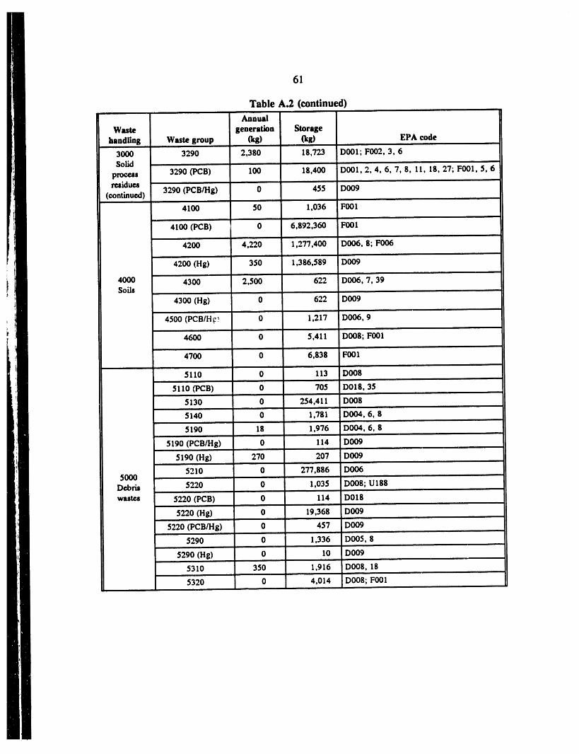
61
Table A.2 (continued)Annual
Waste generation Storage
handling Waste group , (kg) (kg) EPA code ,3000 3290 2,380 18,723 D001; F002, 3, 6Solid
3290 (PCB) 100 18,400 DOOI, 2, 4, 6, 7, 8, 11, 18, 27; FOOl, 5, 6processresidues
3290 (PCB/Hg) 0 455 D009(continued)
4100 50 1,036 F001
41OO (PCB) 0 6,892,360 FOO1
42OO 4,220 1,277,400 DOO6, 8; FO06
42OO (Hg) 350 1,386,589 D009
4000 43OO 2,500 622 DOO6, 7, 39Soils
43OO (Hg) 0 622 D009
45OO (PCB/H_. _ 0 1,217 D006, 9
4600 0 5,411 DOO8; FOOl
47OO 0 6,838 F001
5110 0 113 DO08
5110 (PCB) 0 705 D018, 35
5130 0 254,411 DOO8
5140 ' 0 1,781 DO04, 6, 8
5190 18 1,976 D004, 6, 8
5190 (PCB/Hg) 0 114 DOO9
5190 (Hg) 270 207 DOO9
5210 0 277,886 DOO65000 ....
Debris 5220 0 1,035 DOO8; U188
wastes 5220 (PCB) 0 114 D018 ,,
5220 (Hg) 0 19,368 DOO9
5220 (PCB/Hg) 0 457 DOO9
5290 0 1,336 DO05, 8
5290 (Hg) 0 10 DO09
5310 350 1,916 DO08, 18
5320 0 4,014 DO08; FOOl

62
Table A.2 (continued)
Waste generation Storagehandling Waste group (kg) (kg) EPA code
5330 534" 13,636D_ " '5330_Pcm 0.....I0,315'D'O01,7,35,37,'39;F001,2,35330 (Hg) 0 200 D007, 9;F001
. ,, , , H,., ,.,
5330(Pcsmg) 0 765 D_5390 ..... 0 '4,327 I)018;F001,2,6'....
, m, ,,, . ,.
5000 5390 (PCB) 0 723 F002 ,
Debris 5390 (Hg) 0 3OO DO09, , ,, , ,,
wastes 5390 (PCB/Hg) 0 168 DOO9(continued) .................
5410 550 8,915 D'007; Fo01, 6
5410 (PCB) 70 787 D018, 43; F001,2, 3
' 5420 2,688 " 300 O00i, 2, '7, 8, 35; F001, 2 '
''5420(PcB) 1,350 0 D035; F001,2. ..,. ..
5490 2,250 13,849 FOOl, , ., ,.,,. , •
5490 (Hg) 0 3,219 DOO8, 9; F001, ,, ,,,, , ,
6110 0 414 U158
I" 61_0 ' 0._ 0 D_S .......
6000 6190 " 145" ]1,799 D011; FOOl; UOMX '
Special ........
wastes 6190 (Hg) 0 IOO D008, 9| , ,, ,
6200 251 0 DOO3
62OO (PCB) 0 1 D003
Ill _2_ I 16,924 ' 0 D008 ...........
7000 _2_0 .... 0 2,365 D008m ,,
Inherently 7410 5OO 207 D008hazardous
wastes 7420 0 1,242 "D006
' 7430 (Big) 5'0 621 'DO02,9 ....
Total 770,933 18,841,709L , ,,, ,, ,,,

63
Table A.3. Summary of ORNL Land Disposal Restricted mixed wastewithout identified treatment technologies
i , ii i i i ,i l lll ill1ill ii
Annual
Waste generation Storage
handling Waste group (kg) (kg) EPA code
1100 0 3,455 D001-11; F003; U134
1000 12oo o 155 D001, 213ii
Aqueous 1900 24,464 1,125 D001-11liquids ± • ......
1900o_g) 0 644 D001,4,6,7,s, 10,112100 0 2,755 D001,2,3,9,21;_002,3,5
, I
2190 0 377 D007
2200 0 26 FOOl, 2; D007, 10. 19, 39
2000 2200 (Hg) 0 247 FOOl, 2; D001Organic
2300 0 4,927 D001, 2, 3, 6, 10, 11, 18, 19; F002, 3, 5, 27;liquids
U151
2330 0 1 FO03, 5
2900 3,828 740 FO01-5. D001-10, 1743, U080
2900 (Hg) ' 0 2"_623 D001, 4, 5, 6, 7, 8, I0', F002, 3, 5
3120 0 7",'132 D004, 5, 6, 7, 8, I0, II, 18, 21, 27, 29, 40
312o o DOOS,3120 (TRU) 110,600 2,612,200 DOMX
3130 0 151 D008, 10,.
3160 0 43 D001, 2, 3, 7, 8. 11
3190 3,828 31'195 Dool, 2, 3, 4, 5, 6, 7, 8, 9, 10, 11, F003
3000 3190 (PCB) 0 18 D039
Solid 3190 (Hg) ' 0 1,909 13006, 7, 8, 10processresidues 3210 0 208 DO01
3211 0 621 D006; F003
3212 0 6 F003
3219 0 7 D001•
3230 0 414 F001
3230 (Hg) 0 207 F001II m
3240 0 2,434 D001, 7, 11, 18, 22; F003, 5, U002

I64
Table A.3 (continued)A...,l ..............
Waste generation Storagehandling Wute group (kg) (kg) EPA code
3000 3290 ........ 0 1,001 DOOl, 3, 39, 43; FOOl, 3; U022, 80, 16iSolid
proc_|re_iduea 3290 (Hg) 0 209 Doo6, _); FOOl
(continued)......4,oo ' 0 4 /;oo2,3 "......42oo" o 115 boo5,_,8,'9 ' "
000 , ,, ,, a. , , H.
Soils . 4200!Hg) 0 0.3 i_OO64300 o 320 D_, s, _,7.8.1o511o o 21o boos,7.9 ......
,,,H ,,.=, , ,..
5130 0 2,694 DOO4, 5, 6, 7, S, 9, 10, 11
5130 (Hg) ...... 0 %9 Doo6, 7, 8 ......
5140..... o 459 DOO6 " '5000 ..... 5190 ' 0 " 191,1_12 D004, 7, 8, 11 "
Debris ii, I I
wastes ...... 5220 " 0 ' 7 D005, 7, 9, .., , .,
5310 0 38 DOO5, 7
5330 0 50 DOOl, 39; FOO3
' 5350 ...... o i36 boos .......,, , ,, ,
5440 0 75 D001; F002
6110 " 0 4,042 pool,2, 18-39; F002-5, 27; PO14; UOMXH, ,,
6110 (Hg) 0 36 D006, 7, 8; UI07
6120 "'0 "24" I)00i,2, 11; POl4;_JO04,12, 134,"154 ""6O00
Special 6130 0 " 6"]0 D(_; FO03;P028,29,9'8,106;uo02,12,4,4,50,64_"80,'wastes 154. 163,197
6140 0 21,888 D001, 2, 8, 9; F001, 2, 3, 5; UOO2, 154, 220,239
" 619o 9,_s5 2 Po2_,9s,io_;uoo4,so ',, ,,,
6200 0 2 Dool, 2, 3
7000 7100 0 2,127 DOOl, 2, 5, 7.8, 9, 11, 18, 31, Ul51,, ,. . ..= ,
Inherently 7300 0 0.2 DOOl; P015hazardous ....
wastes 7410 0 208 D008
!' Total 152,405 2,3741'470 "':

Table A.4. Sununary of ORR Land Disposal Restricted mixed waste without identified treatment technologies, ,, , ,,, ,
ORNL Y-12 Plant K-25 Site
Annual Annual Annual _
Waste generation Storage generation Storage generation Storage igroup (kg) (kg) (kg) (kg) (kg) (kg) ,
L
1000 24,464 5,379 17,885 15,813 33,07 ! 170,704
2000 3,828 I 1,696 62.704 177,790 18,706 84,652
3000 114.428 2.131.707 656.974 8.436.312 190.097 37.085.676 _o,
4000 0 439 7.120 9.579.2 !5 388 250.103
5000 0 196.250 8.380 622.950 86. !00 259.817,,
6000 9.685 26.664 396 12.314 9.003 4.687
7000 0 2.335 17.474 4A35 1.234 2.769
Total 152,405 2,374,470 770,933 18,848,829 338,599 37,858,408

APPENDIX B. MIXED WASTE FEED STREAM DATA FOR MWTF

Tab_ B.I. Mixed w_te f_d m_un data f_ I_%VTF
Current AnnualWaste Inve_to_t Generation Worm
Type Location (cu zc! (cu ft) lta_or ContamJLnant
,eq___;_ wa_-.szu_e wT,we,_ 2 _ z6.7z0 ., cr, el, _.,Cr, Ill, _Pl:)e 1_ D
o Po so L_ u. "8; Pc, c.)_ Tent Cove_!l NA
ST-5 @Y-12 U,E. _estnutrR_q; Waste Pi_[e 1 NA Bg
Non-RCRA _ Bg Bulk/D_rummCivic Cente_r so%is Hg cont. U DSEG, Ipc.,.._.sn LLWNoncoMIO.
T--12 WM Sub-Total 564, ;97 28,866
ER e Y-12 Pes_ _bcough Central Plaot U. O_anlcm, Acidm
Z-OIL' rmted Area
BLD. 9_1D 235,566 U, PCB, Oils, Rigi_Transformar Mixed ¥-12
U. Th, B_3, S_l_mte
-" - " ",. xTkZiK (BLg. 9202 )
Bu
Bids 9995 UST 2077-U,2079-U,2 _ U, Organics, _/uNitric Acid Pipeline PJ_MISC. Bulk
Y-12 Process Waste Sub-Total 2,554,500
i@_d Operations U
ppEITrash
Y-12 Wield Operations Sub-Total 7,268,667
iiiii"!IfW M @ OAK RIDGE K-25 SITE U, Cr Dram
C_F Sfudge i_ K- 25,240 U DrumTSCA Inc_j_erato_ Aqh n K- 3, U, PC_, _etal_ DrumU, Sol_mm;l_ Drum
TSCA Scrubber sxowaow 1_ o_
Metbt]_ S_ay_qcJs With Lead K- U ]_Laun Slu e O Drum
_ K- UMisc. Mixed Solxas KK_- NA U, metals BulkOld Quarry

Tsbk B.I (coa_ued)
Current AnnuaWaste Invm}tory Genera_lon
(cult) (cu ft) Major Contsminants lP_rmWaste Description Type Location
K-2S WM Sub-Total 51,653 13,842
E R _ K-25 SITE
U, eCS, _OEga_..Ibs,OilS;X_w_1?K- ZK- process -- 3 : _ u, -
MISC.
K-25 Process Waste Sub-Total 136,250
u_e li x
K-25 Field Operations Sub-Total 77,068
W M @ ORNL U, metals, oolveate DrumMisc. Operational Metal8 Mixed ORHL "700 I00
-jn e ORKL
MISCEWastemprocessed through CentralN__1_t OItNL _0 Misc.126,a27 NA ,, metals, sa_,sg_lTent° Bulk OW_ i/RA Early Action (2009-2 M_ ORNL
ORML Process Wastes Sub-Total ORNL 127,187
Fig_d M x
Operations
PPE/Trash
ORNL Field Operations Sub-Total 331,939
W _ U, metals Sulk
mmtal_ DrumPORTS 4.PORTS
_M_;.al M_Lc_fi_ltr_;Lon Sl,_cje MM_: _ DrumF]LJLEer Tal)JL_ _O_ao 0. ItS_L_eimlvent8
FloorSweepings... _ _ ""metals'U,,_aleWaste Decon. _olxao _F uor ne . s p & br_s U, m84CaJ.8
#luorlne Gen. _.uaqe PORTSGW T & S Tank Clos_l:', M_ _ 1_ ) tP U. _)i_sCleaning & Neut.Tank Sludges

w ..... w •_ _
" I_-II -- L II" _ --I ...... •-- _ --"= • .... "_--' - "--_'"--" ..... " " --_'_' Ill mm-_,,,.,,, ,," ,,,,"_" -_ _- ___-_-_-...-= ..... -...... _-_ "---- _. _-,ws._.. _=-_-_._ ._'>.- ............... _ _'--_:.." .... , ,i ,, i,l l III
Table B.I (cudmmj)
Current _nual
sil-r solo.r s - _ _o,_ 15,_ _F "'"".o_'T._i.oz,_.
" " M 0.,_.1...o.,m.:.Haz. Wamtm Uflit Closure waste
Raas. Qloves_ wlpev, qtc. ___L u, lol_mtmPPE & related debris zrom RFIRFI Related Soils
Lead Duot/Debrls, filters _ lqet41L1LO
U, orc_mJ.cl
Sa Filtp_la_n_ _E ;ittSlt_ dges PORTS 3 1 mmtals. _,,e_"O_l=eetils
_InaTowetst ins 16,_ 2 U, metals
Silver So,ida U, mmtalmLead Solids U. metalsChromium Cont. Solids 2,
,l£|;Vr C_1oth r& PIPE POW/_ ,. sets'..U, bo]Lem_f;s_v_ _. __ _ °'._.,.W Me al Tu s U, a_tllm
.i.._ ._t. Sl._, _x-71o) _ t ., ,o,,,._,. ,-_z-_lum Sludoe Con_. Wastes U, metals, &el .v_a_mM Wa mS u
U, metals -4
Arsenic Cont_q__inated PIP_ --Cont.inated Waste lqets_., t; oU;_:_t:_1
F_el Contaminited Solids U, metalsSolvent Cont. $0iI_ (X-744Y) U, sol_mstsWell Cuttings (soil) I, U, _olvent_PPE and /(is --_Mpchi;m gri_odlpg Sludge 000xDeorDen_: ciotn PORTS 19, , PCBU. PCB, moP,eats701B So£1sS__u_ (X-6_19) U, PCB. _:l_m DrumFloor S_pings
PORTS WM Sub-Total 146,959 22,391
ER • PORTSMOOT_Was_es processed throuQh Central _laqt
x-70_s .o_n .a_ _ces& PORTsX- 5 W. Hold.•-_t_,_.. _.._-. _ _. _ ._ __ o... __=_.PORTS u, Tc, Cr4-6, _. o_|b, so_ntsX-33OProcess su_ia_n_ M_xea PORTS U. Tc, Cr+6, PCB,OLIm, SoL_tm

_w _ __r
m dl_
_ m, I I I I IIII
Tide B.I (mntksmd)
Cuz-rent
Location _. _,
T Fac. _w_
_-623 Gz'mmcJmtt, mr Trmetmmnt U NA• NA
PORTS Process Sub-Total 546,403
Fl,_d Ope.t ionm _ PORTS I0,_I 1
PORTS Field Operations Sub-Total 1S,$93
141mc. !__ tNNu_i+i34 Wutea PAD140c. ee PADPAD,,t.o _'do.p_i:_Y,,,_r-n-, 0.
2t_l
PC:B Debris" icon crete, so_Ls) _A_ O, t_NLsc. 14mtml tearoom
Paducah _ Sub...Total 160,494 8,043
g R e PADUCAH
Wmm.em nrocem_K! through_c_n_rsZ_Yl_a_*_On___o_ _'_ Yard I_ Tc, Cr- - I:AD |;
It F n _ U II. (;_*o
+"' "+i_ '<= ...... 0:_: _tt'",<=C- PCB Spil It 14 PADPAD+-m-+,..m m= ,,+ 0." .,m,mxorla.tm .ot_U, TC. PCB, _:)1P/kD
C- ou S&mCOOt_ TOw 14 PAD Zn'l_nk'¢hl°_l_m°C_"_ +I:I!_ "-.'='+,_:,<=.o....+o1..,,,:.

Tabk B.I (amtkmed)
.ta7aav_zC'reakl t 14 BAD 0. PCB. OilS. CrPAD Cr+6, No. 2 Fuel O11C- to lean£ F c£1£ty PAD U,OLI.Ml_eral 8n£_ta,G_,NaOe
U, PCa, Cr+E, _tz1_-arboa lq_ele# So___1_Nmtc-33v_ vm:,orize= PAD ___IP,__0isC-535 Switchyard PAD
-C- & 11 TOW I U, AS, Zn, Cr+6, Peht, lchloropbenol_-_tL_-__._ __ _-_ "_C-616-Z Slu(km_'_ __0 n PAD O. Cr+3C-616-F Full-Flow _s_0on PAD U, Cr+3, FlvashC-746 TRU Storame ILr4a PAD U_ Tcc-_46-._: w,.. sto_. _e . PAD _, _. ,e_.._",__.__,__,,C-616 Chrom_te Reduct_ofl Fac£ PADConcrete Rubble PAD 0, Tc, PCB. Sol.mrs
PI4uu ToSt°-qv_ usupe PAD UC__ Cn___4_e__rU.r.nd Tr_an PAD 4 U, PCB, SolventsC-404 LL RadLoacc3.ve wast:e ma PAD U, SolventsMISC. PAD
Paducah Process Waste Sub-Total 1.117.842
_FJ.9].d Opeeat Lens
PPE/Trash PADMISC. PAD .j
Paducah Field Operat_on_ Sub-Total 10.133.643
Waste Mana_mamnt Total 924,203 73.242
ER Process Wastes (ER to Plant) Total 4,482,182
ER F£eld Operat£ons Total 17,826,910
APPENDIX C. SUMMARY OF PREVIOUS TREATABILITY STUDIES

APPENDIX C. SUMMARY OF PREVIOUS TREATABILITY STUDIES
Previous Thermal Desorption Studies on ORR Wastes
Pilot-scale technology demonstrations were performed to test the effectiveness of soilwashing and thermal desorption on the removal of mercury and PCBs from Type I andType II soils. The soil-washing process used sodium hypochlorite solutions in the presence ofan ultrasonic vibrator to enhance mercury and PCB removal. The thermal desorption processheated contaminated soil to temperatures ranging from 200 to 430°C in a heated rotary dryerthrough which nitrogen carrier gas was passed. Treatment goals of 12 ppm mercury and 2ppm PCBs in the treated soil were established.
Using thermal treatment, mercury levels were reduced to 23 ppm and therefore did notmeet the 12-ppm treatment goal. PCB levels were reduced to <1 ppm in both soil types usingthermal desorption. Soil washing resulted in -80% removal of mercury and 70% removal ofPCBs from contaminated soils but did not meet the treatment goals for either contaminant.
Previous Final Waste Forms Studies on ORR Wastes
The area of final forms is the latest addition to the RDDT&E efforts within the DOE
complex as well as on the ORR. Therefore, no studies had been commissioned by MMESprior to the writing of this plan. In the future, the subject will receive a great deal of scrutinyand will enjoy much more emphasis.
RADIONUCLIDE REMOVAL AND SOIL WASHING
Many dry or semidry solids as themlal desorption residues or as direct feed will requireradionuclide removal to meet the process treatment objective of <35 pCi/g of uranium sourcematerial per gram of waste so that the disposal option of either a sanitary (if RCRAconstituents are destroyed or delisted) or a RCRA landfill is preserved. In addition, since it isknown that there are other radionuclides in these waste categories, each technology's removalcapability for these miscellaneous constituent shall be assessed, and performance objectives forthe removal of radionuclides other than uranium shall be established.
Two different sets of drivers are involved when discussing radionuclide removal: wastemanagement (WM) drivers and environmental restoration (ER) drivers. Those WM streamsthat will be processed in the MWTF central facility (as opposed to a transportable unit) willnot be returned to their origins but will be prepared for ultimate disposal. On the other hand,ER soils will be returned to the ground since the plan for their treatment is through the use oftransportable units that do not leave the area of contamination. What this means is that thetechnologies for the central facility and for the transportable units may or may not be thesame. The technologies utilized in the transportable units must not destroy the beneficialcharacteristics of the soil. The central facility does not have such a consideration and in factmust consider other things such as the effects of the treatment on the final waste form.
Despite the fact that the goals of the central facility and the transportable units are notexactly the same, they will more than likely rely on the same types of technologies toaccomplish their tasks: selective leaching and selective extraction. Selective leaching is aprocess or combination of processes in which specific species of concern are selectively
77

78
removed by chemical means. This is often referred to as soil washing. The selective nature ofthe process is achieved by adjusting the aqueous solution conditions and chemistry such thatonly the species of interest are made to enter solution as a stable complex in preparation forremoval by various hydrometallurgical unit operations. Solution chemistry is closelycontrolled so that other unwanted components do not enter the solution. Selective extraction isa process or a series of processes which are used to preconcentrate or to completely removespecies of interest from matrix materials such as soils or sludges. The applicability of suchprocesses is a strong function of the species' properties such as density, chemical form, anddistribution within the matrix, as well as (in some cases) its magnetic properties.
One overall assumption has been made by the architect-engineer that covers both ofthese waste stream types: that is, that any stream destined for radionuclide removal that hasvolatiles such as mercury and/or PCBs will be thermally desorbed first. Thermal desorptionprior to radionuclide removal may have a deleterious effect on the leaching process. Thisassumption will be tested.
Previous Radionuclide Removal Studies on ORR Wastes
Treatability studies were performed on three of the subject mixed waste streams. Thesewastes included sludges, oil-solvent mixtures, and soils. Treatability studies were performedby multiple vendors for each waste type. Treatment objectives focused on removing eitherhazardous or radioactive constituents from the waste to allow for disposal. Treatmentobjectives established for each treatability study targeted uranium, beryllium, mercury, andPCBs for removal. Table C. l summarizes the treatability studies, along with their performancedate, scale, objective, and success.
Sludges
Treatability studies were performed on two basic sludge types for uranium removal.Type I sludges are primarily metal hydroxides, which contain uranium, oil, grease, and otherorganics from the physicochemical treatment of metal-beating wastewater. Type II sludges areprimarily calcium carbonates from the West End Treatment Facility clarification andbiodenitrification process, which contain metal hydroxides (e.g., uranium) with only minimalquantities of oil, grease, and other organic constituents. Both sludge types contain -40%solids. Treatability studies performed on these sludges using acid digestion and carbonateextraction are discussed in the following sections.
Acid Digestion
Bench-scale and pilot-plant testing was performed using an acid digestion process toremove uranium from Y-12 Plant sludges contaminated with both uranium and RCRA heavymetals. Effective segregation of the uranium and heavy metals would allow separate disposalof the respective hazardous and radioactive components.
The acid digestion process solubilizes uranium through the addition of hydrochloric acidand sodium hypochlorite at 80°C. Undissolved material is then filtered from the acid brine.Uranium is selectively removed from the acid brine using ion exchange, while other metals areprecipitated from solution via lime and polymer addition. The process is conducted in batchmode to accommodate changes in waste stream characteristics.
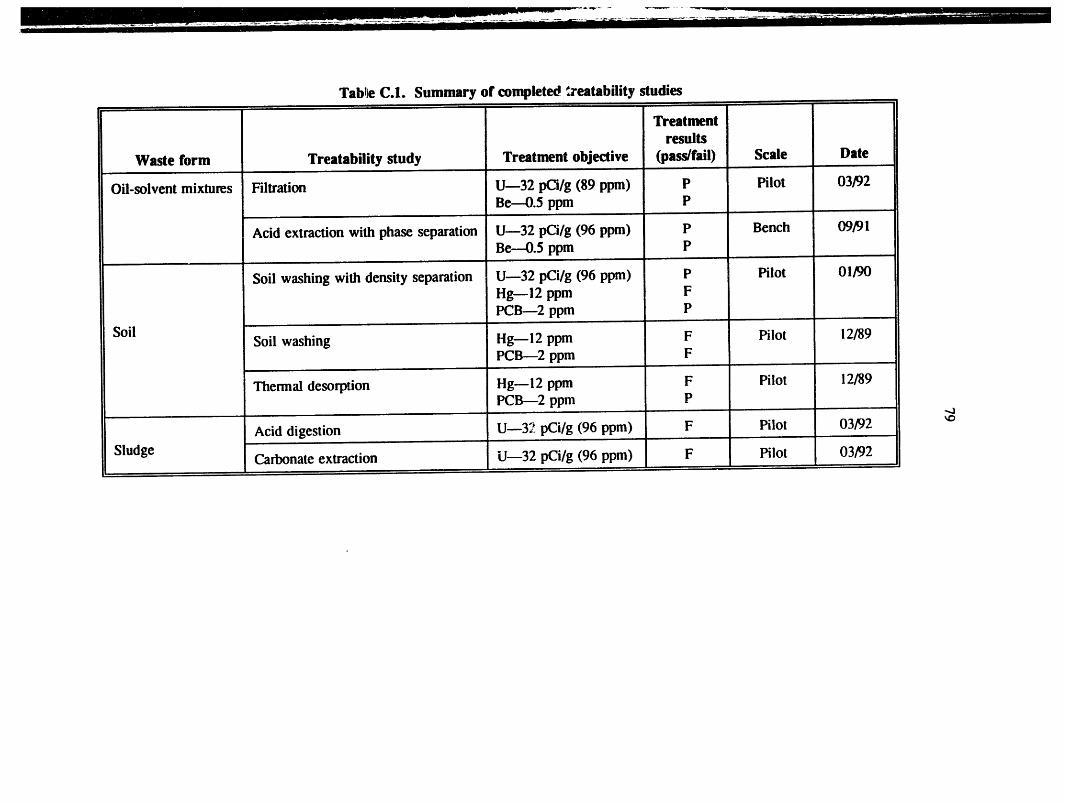
Tab_leC.1. Summary of complete0 _'eatability _tudies
Treatmentresults
Waste form Treatability study Treatment objective (pass/fail) Scale Date
Oil-solvent mixtures Filtration Un32 pCi/g (89 ppm) P Pilot 03/92Be--0.5 ppm P
Acid extraction with phase separation Urn32 pCi/g (96 ppm) P Bench 09/91Be--0.5 ppm P
Soil washing with density separation U--32 pCi/g (96 ppm) P Pilot 01/90Hg--12 ppm FPCB---2 ppm P
Soil Soil washing Hg_12 ppm F Pilot 12/89PCB_2 ppm F
Thermal desorption Hg--I 2 ppm F Pilot 12/89PCB---2 ppm P
-.O
Acid digestion U--3_ pCi/g (96 ppm) F Pilot 03/92 '_
Sludge Carbonate extraction Urn32 pCi/g (96 ppm) F Pilot 03/92

80
The treatment objective of 32 pCi/g (96 ppm) was not reached using this approach,although the treatment process did reach over 93% of the uranium from the feed sludge. OnlyType II sludge was investigated at the pilot-scale level using the process.
Carbonate Extraction
Bench-scale and pilot-scale carbonate extraction treatability tests were performed toremove uranium from inorganic sludges contaminated with both uranium and RCRA heavymetals. A treatment goal of 32 pCi/g (96 ppm) uranium in the treated sludge was established.
This process included several unit processes conducted in the following order. Feedsludges were ground to reduce particle size and increase surface area. Leaching was thenperformed using carbonate/bicarbonate solutions and potassium permanganate. Solids andliquids were separated; then the solids were repulsed, and the leaching process was repeated.The leaching process was repeated three times before the solids were considered ready fordisposal.
The treatment objective of 32 pCi/g (96 ppm) was not reached, although the treatmentprocess did remove over 97% of the uranium from the Type I feed sludge and 82% ofuranium from the Type II feed sludge.
Oil-Solvent Mixtures
Oil-solvent mixtures containing enriched uranium and beryllium in excess of the TSCAincinerator acceptance criteria levels were processed using a filtration technique and an acid-extraction phase-separation technique. Treatment goals of 32 pCi/g uranium and 0.5 ppmberyllium in the waste oil were established for both techniques. These processes are discussedin the following sections.
Filtration
Bench-scale and pilot-scale treatability tests were performed to remove uranium andberyllium from oil-solvent mixtures using two filtration alternatives, The first alternativeinvolved the addition of methanol to reduce feed viscosity, followed by rough screening usinga 100-mesh screen, filtration using a 270-mesh screen and a 10-micron cartridge filter, and,f'mally, effluent polishing using a 0.2-micron cartridge f'dter. The second alternative wasconducted in a similar manner, except a plate-frame, fabric pressure filter with diatomaceousearth was used instead of the 270-mesh screen and cartridge filter.
Alternative 2 produced the best uranium and beryllium removal results. However, thetreatment standard of 32 pCi/g (89 ppm) uranium was achieved for only one waste sample.The beryllium treatment standard of <0.5 ppm was reached for three of four samples, althoughthe maximum initial beryllium concentration for any sample was 0.8 ppm.
Acid Extraction with Phase Separation
Bench-scale treatability tests were performed to measure the effectiveness of removinguranium and beryllium from oil-solvent mixtures using a combination of unit processes,including acid extraction, solvent extraction, and filtration.
Acid extraction was accomplished by solubilizing and separating the uranium andberyllium from the oil-solvent mixture using 6 N hydrochloric acid. Soltrol-100 was added to

81
the acid mixture to facilitate phase separation. The oil and acid phases were backwashed andrecycled to minimize waste stream volume. Undissolved solids were filtered from the oil andacid phases using a microfilter. The process was repeated until the desired results wereachieved.
Treated waste oil concentrations contained -3 ppm uranium and 0.1 ppm beryllium.These concentrations were well below the established treatment goals of 89 ppm uranium and0.5 ppm beryllium. However, for each pound of oil treated, 0.56 to 0.66 pounds of waste acidand waste solids were produced that would require further treatment.
Soils
Treatability studies have been performed on two soil types. Type I consisted of stormsewer sediments contaminated with uranium, mercury, and PCBs. Type II consisted of oillandfarm soil contaminated with uranium and PCBs.
Soil washing with density separation
Pilot-scale technology demonstrations were performed to test the effectiveness of soilwashing and density separation to remove uranium, mercury, and PCBs from Type I andType II soils. The soil-washing process tested was an enhanced chemical extraction processwhich uses compounds such as sodium hypochlorite, acetic acid, and suffactants in an attritionscrubbing environment to promote contact between the extractant and soil by creatingsignificant particle-to- particle interactions. Soils were sieved and contaminants separatedaccording to their differences in density. Treatment goals of 32 pCi/g (96 ppm) uranium,12 ppm mercury, and 2 ppm PCBs in the treated soil were established.
Uranium levels were reduced to 32 ppm in Type I soils and to 63 ppm in Type II soils,both below the 96-ppm treatment goal. PCB levels were reduced to below the 2-ppmtreatment goal for both soil types. Mercury content in the mercury sediments was reducedfrom 840 ppm to 100 ppm, which did not meet the treatment goal of 12 ppm mercury.

83
ORNL/TM-1271$
INTERNAL DISTRIBUTION
1-5. T.J. Abraham 48--49. D.K. Little6. M.L. Baker 50. J.D. Lore7. P.M. Backus 51. C.H. Mattes8. J. Bailey 52. T.E. McDoweU9. M.H. Bartling 53. W.S. McGarvey
10. C.E. Benson 54. M.B. M¢Ghee
11. J.B. Berry 55. L.J. Mezga12. A. Bleier 56. M.I. Morris13. C.F. Boris 57. C.M. Noakes14. C.E. Buttram 58. J.J. Perona15. C.M. Cecala 59. A. Rivera
16-27. T.B. Conley 60. S.M. Robinson28. W.A. Connen 61. T.O. Rogers29. A.G. Croft 62. R.J. Sams
30-31. T.L. Donaldson 63. D.P. Schaefferkoetter32. C. Estes 64. J.W. Snider33. P.A. Flowers 65. R.D. Spence
34. C.E. Frye 66. L.H. Stinton35. V.P. Gilbert 67. T.N. Temes
36-37. T.M. Gilliam 68. H.P. Wayland, Jr.
38. J. Gilpin 69. D.D. West39. A.H. Gorin 70. S.T. Wright40. M.D. Griffith 71. Central Research Library41. C.W. Hancher 72. Y-12 Technical Library42. J.R. Hightower, Jr. Document Reference Center
43-45. D.A. Hutchins 73. ORNL Patent Section46. R.R. Kimmitt 74-75. ORNL Laboratory Records47. R.H. Krabill 76. ORNL Laboratory Records, RC
EXTERNAL DISTRIBUTION
77. Steve Astoria, Gilbert/Commonwealth Engineers and Consultants, 1055 Commerce ParkDrive, Suite 200, Oak Ridge, TN 37830
78. R.W. Morrow, Gilbert/Commonwealth Engineers and Consultants, 1055 CommercePark Drive, Suite 200, Oak Ridge, TN 37830
79-80. Bob Petersen, EET, 129-A Perimeter Park Road, Knoxville, TN 3792281. Louie Sferrazza, EET, 129-A Perimeter Park Road, Knoxville, TN 3792282. S. Trammell, Gilbert/Commonwealth Engineers and Consultants, 1055 Commerce Park
Drive, Suite 200, Oak Ridge, TN 3783083. Office of Assistant Manager, Energy Research and Development, DOE-ORO, P.O. Box
2001, Oak Ridge, TN 3783184-85. Office of Scientific and Technical Information, P.O. Box 62, Oak Ridge, TN 37831

m mI

_L