Embed Size (px)
Citation preview

INSTALLATION MANUAL
ORION™ BARRIER
NCHRP 350 TL-3 Portable Steel Longitudinal Barrier

Lindsay Transportation Solutions Sales and Services, Inc (888) 800-3691 [U.S. toll free] or +1 (707) 374-6800 Lindsay Transportation Solutions Sales and Services, Inc (888) 800-3691 [U.S. toll free] or +1 (707) 374-68002
Table of Contents____________________________
Orion™ Introduction............……………...…...………. 3
System Overview………..………………………........... 3
Before Installation……….………………………........... 3
Limitations & Warnings………………………………… 4
Safety Statements.………………………..……………. 4
System Design & Design Considerations…………… 5
Parts Identification………………………..……………. 6
Bill of Materials….………….…………………………… 6
Installation Preparation………………………….…….. 7
Installation Instructions…………………………………. 8
Installation Examples……………………………..……. 11
Installation Checklist.…………………………………… 12
Maintenance & Repair …..…………………………….. 13
Frequently Asked Questions …………………… ……. 14
Crash Test Summary……….………………………….. 15
APPENDIX – Technical Drawings____________________________
Orion™ – Isometric (with internal)………………….... 17
Orion™ – Plan & Elevation..............…………………. 18
Orion™ – Standard Pinning Configuration................. 19
2
INSTALLATION AND MAINTENANCE MANUAL
18
19
20
6
7
7
8
9
12
13
14
15
16
19
20
21

Lindsay Transportation Solutions Sales and Services, Inc (888) 800-3691 [U.S. toll free] or +1 (707) 374-6800 3
Orion™ Introduction
Introduction
Orion™ is a TL-3 barrier made up of steel units that when joined together using a steel pin and pinned to the ground at each end provides positive work zone barrier protection to temporary construction sites and other miscellaneous roadside activities.
The unique Orion™ internal frames, profile design using standard guardrail panels and steel pin allow the barrier to be installed straight or down to a minimum radius of 355m (1165’) if required.
If required the Orion™ TL-3 barrier can be used with proprietary TL-3 Crash Cushions which negates the need to shield or flare the ends of the barrier.
Orion™ has been designed and tested to meet the evaluation criteria of NCHRP 350 Test Level 3 (TL-3) for a longitudinal barrier.
When correctly installed the system is capable of stopping, containing or re-directing an errant vehicle in a safe manner under NCHRP 350 impact conditions.
System Overview
Orion™ TL-3 barrier is designed and constructed to provide acceptable structural adequacy, minimal occupant risk and safe trajectory as set forth in NCHRP 350 for longitudinal barriers.
When impacted with an 820kg (1810lbs) or 2000kg (4410lbs) vehicle at speeds of up to 100kph(62mph) and angles up to 25 degrees, the impacting vehicle is stopped, re-directed or contained in a safe manner.
Before Installation
Placement of Orion™ shall be in accordance with the design as provided for the temporary work zone. Installation shall be in accordance with the installation instructions supplied for this product.
Depending on the circumstances at the site, installation including unloading (using a flat deck truck with crane hoist) should take no more than 2 minutes for each 11.7m (38’4”) unit.
Orion™ is a highly engineered safety device made up of a relatively small number of parts. Before starting installation ensure that one is familiar with the make up of the system.
3
ORION™ BARRIER

Lindsay Transportation Solutions Sales and Services, Inc (888) 800-3691 [U.S. toll free] or +1 (707) 374-6800 Lindsay Transportation Solutions Sales and Services, Inc (888) 800-3691 [U.S. toll free] or +1 (707) 374-68004
Orion™ Introduction cont.
Limitations and Warnings
Orion™ TL-3 barrier has been rigorously tested and evaluated per the evaluation criteria in the NCHRP 350 guidelines for a longitudinal barrier. The impact conditions recommended in NCHRP 350 are intended to address typical in-service collisions.
When properly installed and maintained Orion™ TL-3 barrier allows an impacting vehicle to be stopped, contained or re-directed in a safe and predictable manner under the NCHRP 350 impact conditions.
Vehicle impacts that vary from the NCHRP 350 impact conditions described for longitudinal barriers may result in significantly different results than those experienced in testing. Vehicle impact characteristics different than, or in excess of, those encountered in NCHRP 350 testing (weight, speed and angle) may result in system performance that may not meet the NCHRP 350 evaluation criteria.
The Orion™ barrier can be installed with proprietary crash cushions. If a crash cushion is not used, the end of the barrier must be shielded or flared as per Road Controlling Authority’sguidelines.
Safety Statements
General Safety
• All required traffic safety precautions should be complied with. All workers should wear required safety clothing (high visibility vests, steel capped footwear, gloves etc.)
• Only authorized trained personnel should operate any machinery. Where overhead machinery is used, care must be taken to avoid any overhead hazards.
• Gloves should be worn at all times.
Orion™ Safety Statements
• All installers must be well clear when unloading the units from the truck deck.
• To aid with placement, guy ropes should be attached to each end of the unit. At no time is it required that an installer be positioned between the units.
• Orion™ is a stand alone barrier except for the end units which are anchored to the ground using pins. Pay particular attention to the SWMS outlined in the installation instructions in this manual when drilling and fixing these pins.
• Each 11.7m (38’4”) unit weighs 900kg (1985lbs) make sure that all equipment used to unload and maneuvre the units are approved for use.
• Final positioning of the units and placement of the steel pin connectors should be done by 1
4
personnel so as to remove the risk of hands and fingers being caught between the components.
System Design & Design Considerations
SlopesA maximum slope of 1:10 is preferable.On slopes greater than this, follow the Road Controlling Authority’s guidelines.
CurbsAs with all road side safety hardware, Orion™ has been designed and tested so that the centre of gravity of the impacting vehicle is at a constant height in relation to the barrier. For this reason, it is preferred that curbs or channels are not in front or behind the barrier as they will result in altering the height of the vehicle at impact. If there is no option but to install in front or behind of a curb advice should be followed from the RoadControlling Authority’s guidelines.
Undulating ground conditionsSite specific grading may be necessary to ensure that there are no “humps” or “hollows” thatmay significantly alter the impacting vehicles stability or substantially alter the barrier height in relation to the ground.
Median and Roadside ApplicationsOrion™ Barrier can be used in both ‘roadside’ and ‘median’ applications.
Point of NeedWhen installed correctly, which includes pinning to the ground at each end, the Orion™ barrier is fully re-directive. Ensure that when installing the barrier that it is of sufficient length. For further details consult the Road Controlling Authority’s guidelines.
End TreatmentThere are a number of proprietary crash cushions that can be used to protect the ends of anOrion™ barrier. Model selection and correct usage shall be in accordance with the manufacturers corresponding instructions. If an end treatment is not used it may be required to flare or shield the barrier as per Road Controlling Authority’s guidelines.
Soil ConditionsThe Orion™ is always anchored at either end, the minimum thickness of either asphalt or concrete is 50mm (2”). Orion™ is installed above ground so soil conditions on site are not applicable, however it is recommended Orion™ is installed on a compacted surface.
5
INSTALLATION AND MAINTENANCE MANUAL

Lindsay Transportation Solutions Sales and Services, Inc (888) 800-3691 [U.S. toll free] or +1 (707) 374-6800 5
STANDARD LIMITED WARRANTY
Lindsay Transportation Solutions, Inc. “LTS” ( formerly Barrier Systems ) has tested the impactperformance of its barriers and crash cushion systems, and other highway safety hardware undercontrolled conditions, however, LTS does not represent nor warrant that the results of those controlledconditions would necessarily avoid injury to persons or property. LTS EXPRESSLY DISCLAIMS ANYWARRANTY OR LIABILITY FOR CLAIMS ARISING BY REASONS OF DEATH OR PERSONALINJURY OR DAMAGE TO PROPERTY RESULTING FROM ANY IMPACT, COLLISION OR HARMFUL CONTACT WITH THE PRODUCTS OR NEARBY HAZARDS OR OBJECTS BY ANYVEHICLE, OBJECTS OR PERSONS.
LTS warrants that any product or component part manufactured by LTS will be free from defects inmaterial or workmanship. LTS will replace free of cost any Product or component part manufactured byLTS that contains such a defect.
THE FOREGOING WARRANTY IS IN LIEU OF AND EXCLUDES ALL OTHER WARRANTIESNOT EXPRESSLY SET FORTH HEREIN, WHETHER EXPRESS OR IMPLIED BY OPERATIONOF LAW OR OTHERWISE, INCLUDING BUT NOT LIMITED TO ANY IMPLIED WARRANTIES OF MERCHANTABILITY OR FITNESS FOR A PARTICULAR PURPOSE.
LTS’ LIABILITY UNDER THIS WARRANTY IS EXPRESSLY LIMITED TO REPLACEMENTFREE OF COST (IN THE FORM AND UNDER THE TERMS ORIGINALLY SHIPPED), OR TO REPAIR OR TO MANUFACTURE BY LTS, PRODUCTS OR PARTS NOT COMPLYING WITHLTS SPECIFICATIONS, OR, AT LTS’ ELECTION, TO THE REPAYMENT OF AN AMOUNTEQUAL TO THE PURCHASE PRICE OF SUCH PRODUCTS OR PARTS, WHETHER SUCH CLAIMS ARE FOR BREACH OF WARRANTY OR NEGLIGENCE. LTS SHALL NOT BE LIABLEFOR ANY INCIDENTAL, CONSEQUENTIAL OR SPECIAL LOSSES, DAMAGES OR EXPENSES OF ANY KIND, INCLUDING, WITHOUT LIMITATION, ANY SUCH LOSSES, DAMAGES OR EXPENSES ARISING DIRECTLY OR INDIRECTLY FROM THE SALE, HANDLING OR USE OF THE PRODUCTS FROM ANY OTHER CAUSE RELATING THERETO, OR FROM PERSONALINJURY OR LOSS OF PROFIT.
Any claim by the Buyer with reference to Products sold hereunder for any cause shall be deemed waived by the Buyer unless LTS is notified in writing, in the case of defects apparent on visual inspection,within ninety (90) days from the delivery date, or, in the case of defects not apparent on visualinspection, within twelve (12) months from the said delivery date. Products claimed to be defective maybe returned prepaid to LTS’ plant for inspection in accordance with return shipping instructions thatLTS shall furnish to the Buyer forthwith upon receipt of the Buyer’s notice of claim. If the claim is established, LTS will reimburse that Buyer for all carriage costs incurred hereunder.
The forgoing warranty benefits shall not apply to (i) any Products that have been subject to improperstorage, accident, misuse or unauthorized alterations, or that have not been installed, operated andmaintained in accordance with approved procedures and (ii) any components manufactured by the Buyer.
W030587 Rev. 8 revised February 4, 2013
180 River Road • Rio Vista, CA 94571 • Tel. +1 (707) 374-6800 • Fax. +1 (707) 374-6801
ORION™ BARRIER

Lindsay Transportation Solutions Sales and Services, Inc (888) 800-3691 [U.S. toll free] or +1 (707) 374-6800 Lindsay Transportation Solutions Sales and Services, Inc (888) 800-3691 [U.S. toll free] or +1 (707) 374-68006
personnel so as to remove the risk of hands and fingers being caught between the components.
System Design & Design Considerations
SlopesA maximum slope of 1:10 is preferable.On slopes greater than this, follow the Road Controlling Authority’s guidelines.
CurbsAs with all road side safety hardware, Orion™ has been designed and tested so that the centre of gravity of the impacting vehicle is at a constant height in relation to the barrier. For this reason, it is preferred that curbs or channels are not in front or behind the barrier as they will result in altering the height of the vehicle at impact. If there is no option but to install in front or behind of a curb advice should be followed from the RoadControlling Authority’s guidelines.
Undulating ground conditionsSite specific grading may be necessary to ensure that there are no “humps” or “hollows” thatmay significantly alter the impacting vehicles stability or substantially alter the barrier height in relation to the ground.
Median and Roadside ApplicationsOrion™ Barrier can be used in both ‘roadside’ and ‘median’ applications.
Point of NeedWhen installed correctly, which includes pinning to the ground at each end, the Orion™ barrier is fully re-directive. Ensure that when installing the barrier that it is of sufficient length. For further details consult the Road Controlling Authority’s guidelines.
End TreatmentThere are a number of proprietary crash cushions that can be used to protect the ends of anOrion™ barrier. Model selection and correct usage shall be in accordance with the manufacturers corresponding instructions. If an end treatment is not used it may be required to flare or shield the barrier as per Road Controlling Authority’s guidelines.
Soil ConditionsThe Orion™ is always anchored at either end, the minimum thickness of either asphalt or concrete is 50mm (2”). Orion™ is installed above ground so soil conditions on site are not applicable, however it is recommended Orion™ is installed on a compacted surface.
5
INSTALLATION AND MAINTENANCE MANUAL

Lindsay Transportation Solutions Sales and Services, Inc (888) 800-3691 [U.S. toll free] or +1 (707) 374-6800 7
System Design & Design Considerations cont DeflectionTest 3-11 2000kg (4410lbs) pickup truck, 25 degree angle at 100kph (62mph).
Dynamic Deflection Permanent Deflection Working Width 1.85m 1.85m 1.85m
Test 3-10. 820kg (1810lbs) car, 20 degree angle at 100kph (62mph).
Dynamic Deflection Permanent Deflection Working Width 1.45m 1.45m 1.45m
Orion™ - Parts Identification
11.7m Orion Unit Steel Pin Connector (Galvanised Steel) (hot dipped galvanised)
Orion™ - Bill of MaterialsFor every 11.7m (38’4”) of temporary barrier the following components are required:
• 11.7m (38’4”) Orion Unit1 required
• Steel Pin Connector1 required
Note: Results are from actual crash testing and the test article length was 70m(230’).Results from Test 3-11(NCHRP 350) are the published TL-3 Deflection.
6
ORION™ BARRIER

Lindsay Transportation Solutions Sales and Services, Inc (888) 800-3691 [U.S. toll free] or +1 (707) 374-6800 Lindsay Transportation Solutions Sales and Services, Inc (888) 800-3691 [U.S. toll free] or +1 (707) 374-68008
• M24 (1’) Anchor Pins & Nuts (450mm (18”) Asphalt & 150mm (6”) Concrete)16 required for entire barrier regardless of length
Orion™ - Installation Preparation
Getting Started
It is essential that Orion™ TL-3 barrier is installed correctly. Please carefully read and understand the following instructions before installing.
Note: These instructions relate only to the installation of Orion™ and are for standard installations only.
Orion™ is designed so that it has exactly the same components and barrier setup whether in a ‘roadside’ or ‘median’ application. For all installations, start at one end and connect the units together until the correct barrier length and position is achieved.
Preparation
Before installing Orion™, ensure that all components required for the system are on site andhave been identified. Orion™ barrier is a highly engineered safety device made up of relatively small number of parts. Before starting installation ensure that one is familiar with the make up of the system. Refer to the Parts Identification and Bill of Materials section in this manual for more information.
Ensure that the area where Orion™ is to be installed is flat enough and compacted so that theground conditions will not significantly alter the height of the vehicle in relation to the height of the barrier.
Minor site grading may be required.
Tools Required
The 11.7m (38’4”) long Orion™ units weigh approx 900kg (1985lbs) each so placement and maneuvering must be done by a crane hoist or similar. All lifting equipment used must be certified for use and undertaken by approved personnel.
A lifting device specifically designed for the Orion™ is available which can attach and release from the barrier unit remotely. This negates the need for personnel to manually attach lifting devices to the Orion™ when on the ground, truck deck or stacked for storage. For further information contact your Orion™ distributer.
The units at either end are fixed to the ground using 8x M24 (1”) anchor pins each so a 28mm(1⅛”) diameter drill bit, drill and generator will be required on site.
Note: Installations may be in either asphalt or concrete and anchor depth will be either 450mm(18”) or 150mm (6”) respectively.
7
INSTALLATION AND MAINTENANCE MANUAL

Lindsay Transportation Solutions Sales and Services, Inc (888) 800-3691 [U.S. toll free] or +1 (707) 374-6800 9
Orion™ - Installation Instructions
Step 1 – Site Preparation
It is preferred that Orion™ barrier is installed on compacted flat, level ground.
Ensure that sufficient width and traffic control is available before installing Orion™. Due to the length and weight of the units, deployment will be from a flat deck truck or similar.
Orion barrier should be installed in a tangent position to the direction of travel.
NEVER PLACE HANDS OR FINGERS BETWEEN THE UNITS WHEN MANEUVERING
Step 2 – Connecting to the Barrier Units
Connect the lifting hooks and chain to the 2 lifting eyes located on the intermediateframes. (shown in Figure 1)
When the load is taken up on the barrier and chain make sure that the hook has maintained the correct orientation in order to take the weight. (shown in Figure 2)
8
ORION™ BARRIER

Lindsay Transportation Solutions Sales and Services, Inc (888) 800-3691 [U.S. toll free] or +1 (707) 374-6800 Lindsay Transportation Solutions Sales and Services, Inc (888) 800-3691 [U.S. toll free] or +1 (707) 374-680010
Figure 1. Figure 2.
Orion™ - Installation Instructions
Step 3 – Lifting the Barrier Units
Lift the unit from the truck deck and manoeuvre to the approximate position. (shown in Figures 3 & 4)
The use of guy ropes at each end is recommended.
Figure 3. Figure 4.
Step 4 – Placement of the Barrier Units
Slowly lower down and into the correct position so that the 2 vertical holes on the end frames of each unit line up. (shown in Figure 5 & 6)
At no time is it required that installation personnel are positioned between the units.
Figure 5. Figure 6.
9
INSTALLATION AND MAINTENANCE MANUAL
Lindsay Transportation Solutions Sales and Services, Inc (888) 800-3691 [U.S. toll free] or +1 (707) 374-6800 11
WARNING: Be extremely careful that hands and fingersare well clear of the barrier ends at all times.
Orion™ - Installation Instructions
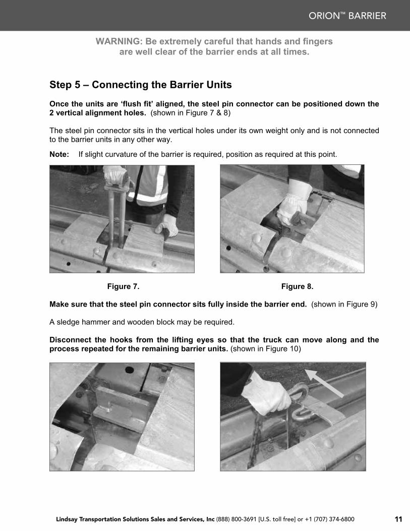
Step 5 – Connecting the Barrier Units
Once the units are ‘flush fit’ aligned, the steel pin connector can be positioned down the 2 vertical alignment holes. (shown in Figure 7 & 8)
The steel pin connector sits in the vertical holes under its own weight only and is not connected to the barrier units in any other way.
Note: If slight curvature of the barrier is required, position as required at this point.
Figure 7. Figure 8.
Make sure that the steel pin connector sits fully inside the barrier end. (shown in Figure 9)
A sledge hammer and wooden block may be required.
Disconnect the hooks from the lifting eyes so that the truck can move along and the process repeated for the remaining barrier units. (shown in Figure 10)
10
WARNING: Be extremely careful that hands and fingersare well clear of the barrier ends at all times.
Orion™ - Installation Instructions
Step 5 – Connecting the Barrier Units
Once the units are ‘flush fit’ aligned, the steel pin connector can be positioned down the 2 vertical alignment holes. (shown in Figure 7 & 8)
The steel pin connector sits in the vertical holes under its own weight only and is not connected to the barrier units in any other way.
Note: If slight curvature of the barrier is required, position as required at this point.
Figure 7. Figure 8.
Make sure that the steel pin connector sits fully inside the barrier end. (shown in Figure 9)
A sledge hammer and wooden block may be required.
Disconnect the hooks from the lifting eyes so that the truck can move along and the process repeated for the remaining barrier units. (shown in Figure 10)
10
ORION™ BARRIER

Lindsay Transportation Solutions Sales and Services, Inc (888) 800-3691 [U.S. toll free] or +1 (707) 374-6800 Lindsay Transportation Solutions Sales and Services, Inc (888) 800-3691 [U.S. toll free] or +1 (707) 374-680012
Figure 9. Figure 10.
Orion™ - Installation Instructions
Step 6 – Anchoring the end units to the ground.
To complete the installation it is required that the barrier at each end is anchored to the ground by 8 pins through the feet of the barrier frames. (shown in Figure 11 & 12)
Instructions on the standard pinning configuration are contained in the Appendix in this manual.
For further information on pin orientation, fixing agent to use and drilling techniques contact your nearest Orion™ distributer.
Figure 11. Figure 12.
Orion™ – Installation Example
Orion™ – Straight Installation
11
INSTALLATION AND MAINTENANCE MANUAL

Lindsay Transportation Solutions Sales and Services, Inc (888) 800-3691 [U.S. toll free] or +1 (707) 374-6800 13
Note: A minimum 355m (1165’) radius can be achieved when using the standard 11.7m(38’4”) long unit. A tighter 124m (4880’) radius can be achieved when the special 4.1mlong units are used.
INSTALLATION CHECKLIST FOROrion™
LocationInstalled By DateInspected By Date
Y/N N/A
•The units are positioned on level ground.
•The set-out of the barrier is as per the design instructions.
•The lugs of each end frame have a ‘flush fit’ with each other and the steel pin connector is positioned through both vertical holes in the end frame of each unit.
•The steel pin connector used to join the units together is fully inserted. (shown in photo below)
•The end units at either end of the barrier are anchored to the ground. Each unit has 8x M24 (1”) anchor pins through the feet of the units and the fastening details are as per manufacturers’recommendations.
• Additional pins are installed along the length of the barrier as per manufacturers’ recommendations if the ‘low deflection’ alternative is required.
• If required the end of the barrier must be protected using a TL-3proprietary crash cushion or shielded or flared as per Road Controlling Authority’s guidelines.
•Attach delineation as required by the Road Controlling Authority.
Comments:
12
ORION™ BARRIER

Lindsay Transportation Solutions Sales and Services, Inc (888) 800-3691 [U.S. toll free] or +1 (707) 374-6800 Lindsay Transportation Solutions Sales and Services, Inc (888) 800-3691 [U.S. toll free] or +1 (707) 374-680014
Orion™ – Maintenance and Repair
Maintenance
Orion™ TL-3 steel barrier is maintenance free.
As with all galvanised systems the barrier will not be immune to corrosion over long periods of time and depending on the circumstances on site, the useful life of the barrier can be expected to be approx 25 years.
All splice bolts are machine tightened when manufactured are fixed with ‘lock tight’ so to resist vibration and remain in place as intended.
Repair
After a typical impact
Recommended tools:• Flat deck truck• Crane Hoist or similar complete with appropriate lifting equipment• A crow bar or similar• A hand held angle grinder complete with cutting wheel
Replacement parts required for a severe impact:• Orion™ Steel Units• Steel Pin Connectors• If the End Units and anchor points are damaged contact your nearest Orion™ distributer.
Key Steps:• Separate the damaged components by removing the steel pin connectors. (it may be
necessary to cut or pry the components apart)• Assess which components are damaged and replace with new parts accordingly.• Connect replacement units to the undamaged section of the barrier and align as required.• Fit the replacement steel pin connectors between each unit.
For further information consult the Orion™ Installation Instructions section in this manual.13
INSTALLATION AND MAINTENANCE MANUAL

Lindsay Transportation Solutions Sales and Services, Inc (888) 800-3691 [U.S. toll free] or +1 (707) 374-6800 15
After fire damage
Orion™ is made entirely out of steel and joined together using steel pin connectors. Therefore it is highly unlikely that even under extreme conditions, like large fires, that the components of the system can be damaged. The galvanised surface of the components does have the ability to resist extreme heat for short periods of time due to the chemical make up. If however the barrier units are deemed unfit for use, replace the damaged units as described above and as outlined in the Orion™ Installation Instructions section in this manual.
Orion™ – Frequently Asked Questions
1) What type of equipment is required to install Orion™?Each unit weighs 900kg (1985lbs) so to unload and position a crane hoist or similar with approved lifting equipment must be used. Units are joined together by simply fitting the steel pin connectors by hand. A drill is also required when fixing the end units to the ground with the M24(1”) anchor pins.
2) Does your company provide spare parts? What is the lead-time for supply?It is important to fix a damaged barrier as soon as possible because it most probably won’t perform as required when damaged. Replacement components are available from your nearest Orion™ distributer.
3) On average, how long does it take to install an Orion™ Barrier?Depending on the application and circumstances at the site, installation and assembly of the system should take approx. 2 minutes to install each 11.7m (38’4”) unit.
4) What about vandalism, can Orion™ be easily damaged?The units are constructed using steel guardrail panels and frames that would not easily be damaged. The construction is similar to ‘other’ steel guardrail barriers and this is not considered an issue.
5) How easily can Orion™ be restored after impact?The system is made up of very few components and is modular so easily repaired. A flat deck truck with a crane hoist, crow bar and hand held angle grinder with cutting wheel may berequired to reinstate.
6) What maintenance is required? What is the expected performance life?Orion™ is a maintenance free barrier. All components are galvanised steel and unless damaged or subjected to conditions worse than ‘normal’ a unit has an expected useful lifespan of 25 years.
7) What is the Deflection of Orion™ Barrier?The maximum deflection recorded during actual crash testing with the standard anchoring set up at TL-3 was 1.85m. If additional pins are installed along the length of the barrier as per manufacturers’ recommendations the resulting barrier is a ‘low deflection’ alternative with a 0.95m deflection.
8) What is Orion™ Barrier connected to?14
ORION™ BARRIER

Lindsay Transportation Solutions Sales and Services, Inc (888) 800-3691 [U.S. toll free] or +1 (707) 374-6800 Lindsay Transportation Solutions Sales and Services, Inc (888) 800-3691 [U.S. toll free] or +1 (707) 374-680016
Orion™ is always anchored at either end unit using 8x M24 (1”) anchor pins connected to the ground. For further information on pin orientation, fixing agent to use and drilling techniques contact your nearest Orion™ distributer.
9) In a leading position, how can the end of the barrier be protected?If required the end unit of an Orion™ barrier can be protected using a proprietary TL-3 crash cushion. For further details consult manufacturers’ instructions.
Orion™ – Crash Test Results Summary
A total of 4 official crash tests where run on the Orion™. These tests cover all that arerequired by NCHRP 350 at Test Level 3 (TL-3) for a longitudinal barrier.
Test…………… 3-10Test Article…… Orion™ (length 70m (230’))CIP………….… 26.5m (87’) downstream
Test Vehicle…. 820 kg Car (1810 lbs)Speed………… 100 kph (62 mph)Impact Angle… 20 deg (Impact Severity = 40.6kJ)
Test…………… 3-11Test Article…… Orion™ (length 70m (230’))CIP………….… 27.0m (89’) downstream
Test Vehicle…. 2000 kg Pickup Truck (4410 lbs)Speed………… 100 kph (62 mph)Impact Angle… 25 deg (Impact Severity = 137.8kJ)
15
INSTALLATION AND MAINTENANCE MANUAL

Lindsay Transportation Solutions Sales and Services, Inc (888) 800-3691 [U.S. toll free] or +1 (707) 374-6800 17
Orion™ – Crash Test Results Summary cont
Test…………… 3-21Test Article…… Orion™ (length 49.2m (161’))CIP………….… 36.9m (121’) downstream
Test Vehicle…. 2000 kg Pickup Truck (4410 lbs)Speed………… 100 kph (62 mph)Impact Angle… 25 deg (Impact Severity = 137.8kJ)
Test…………… 3-11 (Fully Pinned)Test Article…… Orion™ (length 47.7m (156’))CIP………….… 35.8m (117’) downstream
Test Vehicle…. 2000 kg Pickup Truck (4410 lbs)Speed………… 100 kph (62 mph)Impact Angle… 25 deg (Impact Severity = 137.8kJ)
16
ORION™ BARRIER
Lindsay Transportation Solutions Sales and Services, Inc (888) 800-3691 [U.S. toll free] or +1 (707) 374-6800 Lindsay Transportation Solutions Sales and Services, Inc (888) 800-3691 [U.S. toll free] or +1 (707) 374-680018
For all tests above the vehicles where safely re-directed by the Orion™ barrier. The vehicles did not penetrate, underride or override the test installations. The test article was judged to have satisfied the requirements of NCHRP Report 350 criteria TL-3 for a longitudinal barrier.
Note: In all tests, only the unit at either end of Orion™barrier was pinned to ground. This pinning arrangement was validated when impacted in Test 3-21.
Test 3-11 (Fully Pinned) was run with an additional pin at every 3.81m (12’6”), through the foot of an Orion™ frame on the traffic face only. This was to validate a ‘low deflection’ alternative.
APPENDIX – Technical Drawings
17
INSTALLATION AND MAINTENANCE MANUAL

Lindsay Transportation Solutions Sales and Services, Inc (888) 800-3691 [U.S. toll free] or +1 (707) 374-6800 19
Orion™ – Isometric (with internal)APPENDIX – Technical Drawings (continued)
18
ORION™ BARRIER

Lindsay Transportation Solutions Sales and Services, Inc (888) 800-3691 [U.S. toll free] or +1 (707) 374-6800 Lindsay Transportation Solutions Sales and Services, Inc (888) 800-3691 [U.S. toll free] or +1 (707) 374-680020
Orion™ – Plan and ElevationAPPENDIX – Technical Drawings (continued)
19
INSTALLATION AND MAINTENANCE MANUAL

Lindsay Transportation Solutions Sales and Services, Inc (888) 800-3691 [U.S. toll free] or +1 (707) 374-6800 21
Orion™ – Standard Pinning Configuration
20
ORION™ BARRIER

Lindsay Transportation Solutions Sales and Services, Inc (888) 800-3691 [U.S. toll free] or +1 (707) 374-6800 Lindsay Transportation Solutions Sales and Services, Inc (888) 800-3691 [U.S. toll free] or +1 (707) 374-680022
INSTALLATION AND MAINTENANCE MANUAL
Lindsay Transportation Solutions Sales and Services, Inc (888) 800-3691 [U.S. toll free] or +1 (707) 374-6800 23
ORION™ BARRIER

Lindsay Transportation Solutions Sales and Services, Inc 180 River Road • Rio Vista, CA 94571 • +1 707.374.6800 U.S. Toll Free: 888.800.3691 • www.barrriersystemsinc.com
Installation manual details for the Orion System are subject to change without notice to reflect improvements and upgrades.Additional information is available from Lindsay Transportation Solutions Sales and Service © Lindsay Transportation Solutions
ORION 07022014 v4