Embed Size (px)
Citation preview

GAGE BILT TOOLS ARE AVAILABLE WORLDWIDE E-MAIL US FOR A DISTRIBUTOR NEAR YOU.
INSTALLATION TOOL
GB745
ORIGINAL INSTRUCTIONS
44766 Centre Court Clinton Twp. MI 48038 USA Ph: +1 (586) 226-1500 Fax: +1 (586) 226-1505
[email protected] / www.gagebilt.com
GAGE BILT
MADE in USA
2 Rev. 6/18
GB745 INSTALLATION TOOL
TABLE OF CONTENTS
Page
EU Conformity and Warranty ................................................................................................................................................... 3
Description and Technical Specifications ............................................................................................................................... 4
Description of Functions ........................................................................................................................................................... 5
Warnings ..................................................................................................................................................................................... 6
Principle of Operation ............................................................................................................................................................... 7
How to set-up the GB745 ........................................................................................................................................................... 8
How to use the GB745 ............................................................................................................................................................... 9
Maintenance and Hydraulic Thread Preparation ................................................................................................................... 10
Filling & Bleeding ................................................................................................................................................................ 11-12
Troubleshooting / Overhaul ............................................................................................................................................... 13-15
Parts Lists ................................................................................................................................................................................. 16
DEXRON® III Oil Safety Data (SDS) ........................................................................................................................................ 17
Nose Assembly Selection Chart and Accessories ............................................................................................................... 18
Accessories ............................................................................................................................................................................. 20
3 Rev. 6/18
GB745 INSTALLATION TOOL
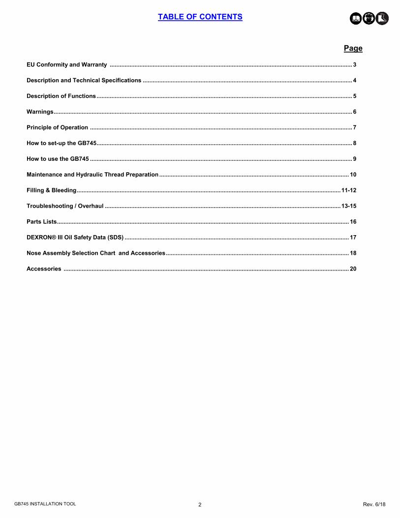
Seller warrants that all goods covered by this catalog will conform to applicable specifications and will replace or repair, EXW our plant, any goods providing defective from faulty workmanship, or material, for 1 year
from date of shipment. Said warranty to remain in effect if, and only if, such goods are used in accordance with all instructions as to maintenance, operation and use, set forth in manuals and instruction sheets furnished by seller. Sellers obligation under this warranty shall be limited to the repair or rework of the goods supplied or replacement thereof, at Seller’s option, and in no case is to exceed the invoice value of said goods. Under no circumstances will the seller be liable for incidental or consequential damages or for damages incurred by the buyer or subsequent user in repairing or replacing defective goods or if the goods covered by this warranty are reworked or subjected to any type of additional processing. This warranty is void if Seller is not notified in writing of any rejections or defects within 1 year after the receipt of the material by the customer. THIS WARRANTY IS MADE IN LIEU OF ALL OTHER WARRANTIES EXPRESSED OR IMPLIED, INCLUDING MERCHANTABILITY.
WARRANTY
DECLARATION OF CONFORMITY MANUFACTURER: Gage Bilt Inc. 44766 Centre Ct. Clinton Twp. Michigan U.S.A. +1(586-226-1500)
WE DECLARE THAT THE EQUIPMENT SPECIFIED HEREIN CONFORMS TO THE FOLLOWING DIRECTIVES AND STANDARDS
Machinery Directive 2006/42/EC
EN12100-1 & EN12100-2
EN792-1:2000+A1
EU REPRESENTATIVE: Edgar Hausmann GmbH Förster-Busch-Str. 10 D-34346 Hann. Münden Germany
EQUIPMENT DESCRIPTION: GB745 FASTENER INSTALLATION TOOL
This product specified above conforms to the above dIrectives and standards.
SIGNATURE:
NAME: BRIAN LEIGH
PRODUCT MANAGER CLINTON TWP., MI U.S.A. MAY 2010 +1(586) 226-1500
GAGE BILT
4 Rev. 6/18
GB745 INSTALLATION TOOL
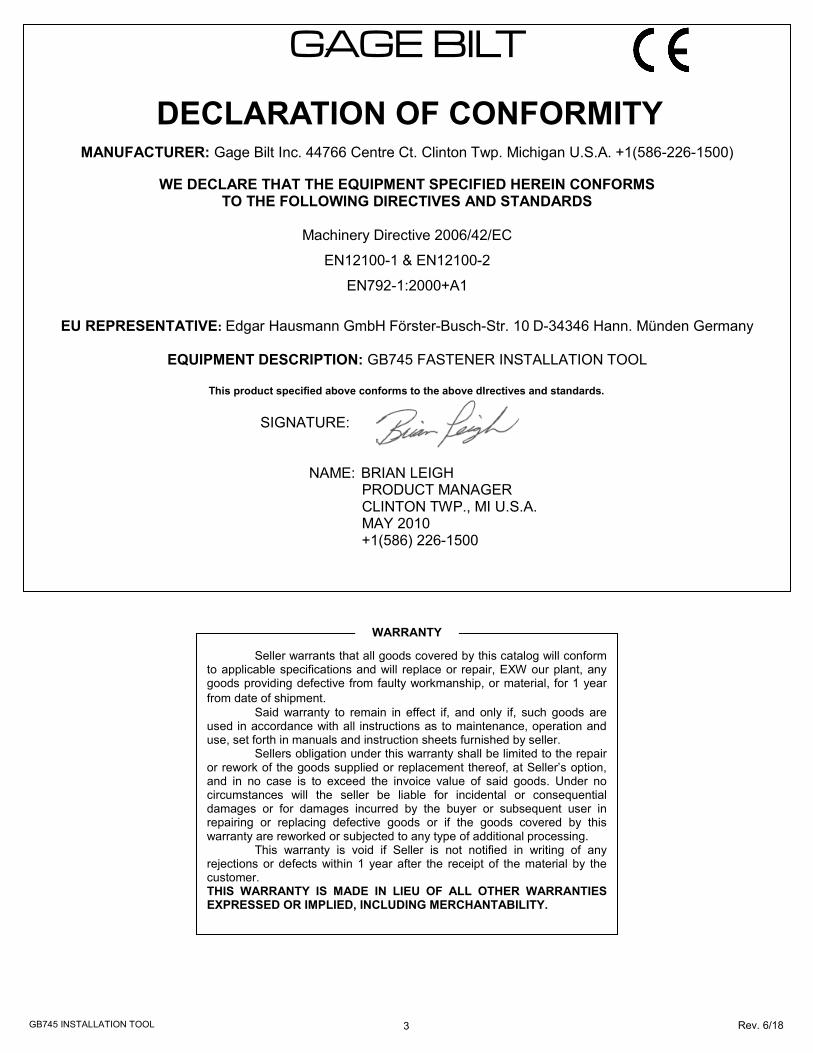
SPECIFICATIONS
Hand Held Weight - 7.20 lbs. (3.26 kg) Air pressure req'd - 90-100 p.s.i. (6.2-6.9 bar) Max. Air consumption - .30 SCF/cycle (8.50 L/cycle) Hydraulic Oil - Automatic Transmission Oil,
Dexron III, or equivalent. Setting stroke - .620" (15.75 mm) Rated pull load - 6,200 lbs. (27.57 kN) Noise level - 81.5 dB(A)
Vibration - Tested– No hazards found.
The GB745 is a pneumatic-hydraulic tool designed specifically for the efficient installation of blind rivets, lockbolts and MAGNA-GRIP® fasteners. It weighs just over 7.2 lbs. (3.26 kg) and can be operated in any position. It has a .620” (15.75 mm) rivet setting stroke and a rated pull load of 6,200 lbs (27.57 kN) with 90 psi (6.2 bar) air pressure at the air inlet. The GB745 riveter operates on 90 to 100 psi (6.2-6.9 bar) of air pressure, with 90 psi. (6.2bar) providing maximum efficiency. At 90 psi. (6.2bar) of air pressure, the GB745 does not exceed 81.5 dB(A) and consumes .30 SCF/cycle (8.50 L/cycle). The air inlet is provided with 1/4-18 female pipe thread for accepting the user's air hose fitting. Nose Assemblies that were designed for the model 353 installation tool mount directly on the GB745 without the use of an adapter. Nose Assemblies that were designed for the model 352 installation tool will attach to the GB745 with the use of the adapter assy (745751). NOSE ASSEMBLIES ARE NOT FURNISHED WITH THIS TOOL AND MUST BE ORDERED SEPARATELY (SEE NOSE ASSEMBLY SELECTION CHART PAGE 18).
DESCRIPTION
WARNING: Any other use is forbidden.
ENVIRONMENTAL USE
WARNING: Do not operate in an explosive atmosphere.
The GB745 can be operated between 0ºF — 118ºF (-17.8ºC / 47.8ºC)
5 Rev. 6/18
GB745 INSTALLATION TOOL
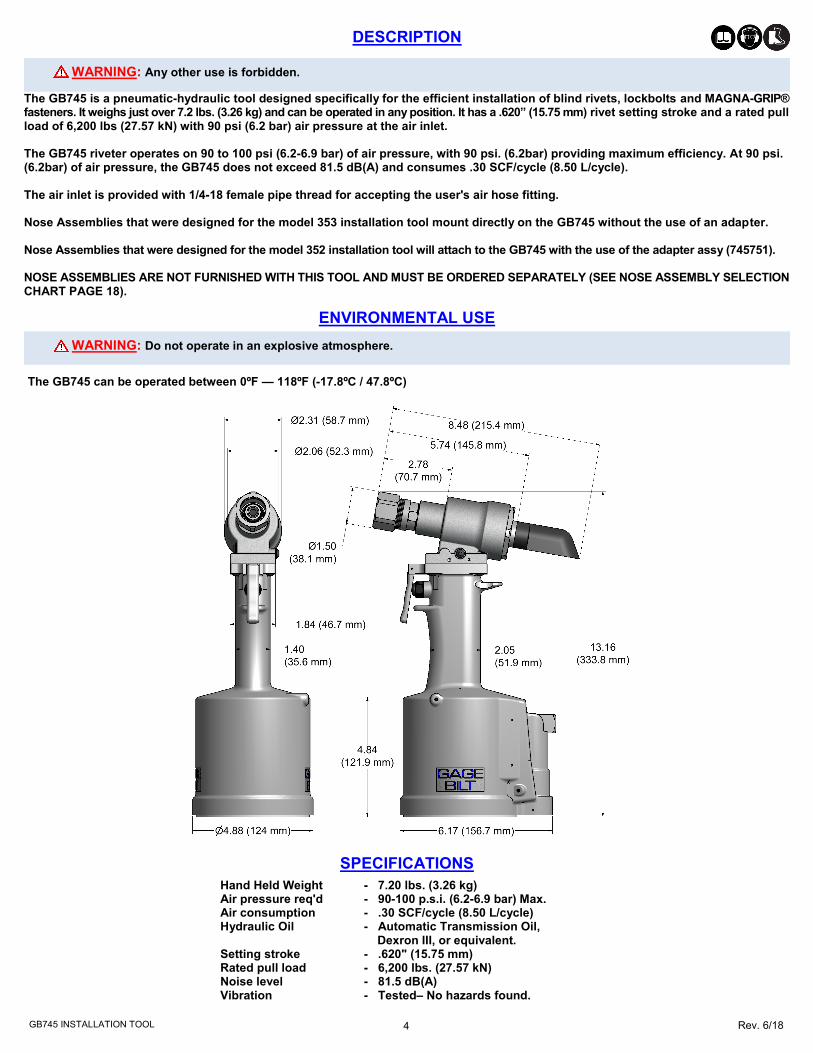
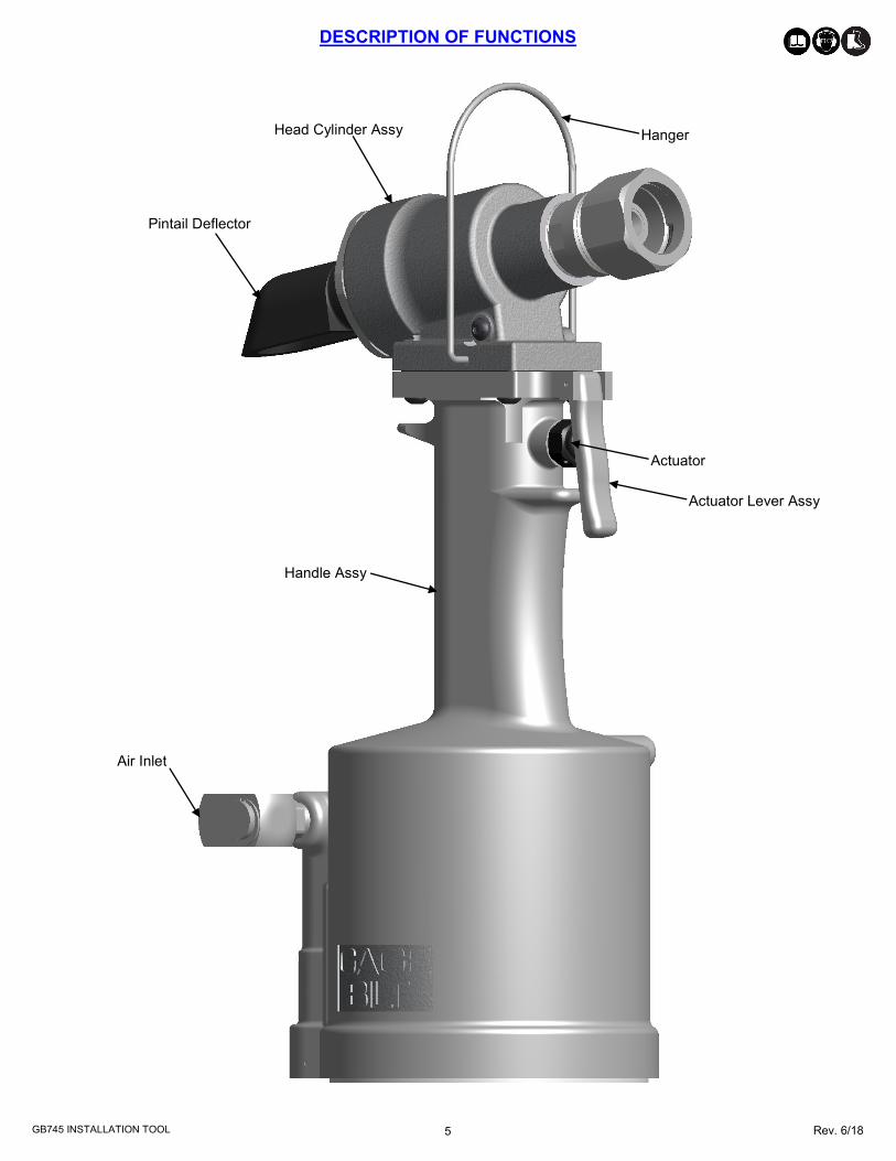
DESCRIPTION OF FUNCTIONS
Actuator
Handle Assy
Head Cylinder Assy
Pintail Deflector
Air Inlet
Actuator Lever Assy
Hanger
6 Rev. 6/18
GB745 INSTALLATION TOOL
SAFETY WARNINGS
GENERAL SAFETY RULES:
1. For multiple hazards, read and understand the safety instructions before installing, operating, repairing, maintaining, changing accessories on, or working near the
assembly power tool for non-threaded mechanical fasteners. 2. Only qualified and trained operators should install, adjust or use the assembly power tool for non threaded mechanical fasteners. 3. Do not modify this assembly power tool for non-threaded mechanical fasteners. Modifications can
reduce effectiveness of safety measures and increase the risks to the operator. 4. Do not discard safety instructions; give them to the operator. 5. Do not use assembly power tool for non-threaded mechanical fasteners if it has been damaged. 6. Tools shall be inspected periodically to verify all ratings and markings required are
legible. The employer/user shall contact the manufacturer to obtain replacement marking labels when necessary.
7. Air under pressure can cause severe injury. 8. Always shut off air supply, drain hose of air pressure and disconnect tool from air
supply when not in use, before changing accessories or when making repairs. 9. Never direct air at yourself or anyone else. 10. Whipping hoses can cause severe injury. Always check for damage or loose hoses and fittings. 11. Cold air shall be directed away from hands. 12. Whenever universal twist couplings (claw couplings) are used, lock pins shall be
installed and whipcheck safety cables shall be used to safeguard against possible hose-to-tool or hose-to-hose connection failure.
13. Do not exceed the maximum air pressure stated on the tool or manual. 14. Never carry an air tool by the hose.
ADDITIONAL SAFETY RULES FOR PNEUDRAULIC POWER TOOLS:
1. Air under pressure can cause severe injury. 2. Always shut off air supply, drain hose of air pressure and disconnect tool from air
supply when not in use, before changing accessories or when making repairs. 3. Never direct air at yourself or anyone else. 4. Whipping hoses can cause severe injury. Always check for damage or loose hoses and fittings. 5. Cold air shall be directed away from hands. 6. Whenever universal twist couplings (claw couplings) are used, lock pins shall be
installed and whipcheck safety cables shall be used to safeguard against possible hose-to-tool or hose-to-hose connection failure.
7. Do not exceed the maximum air pressure stated on the tool or manual. 8. Never carry an air tool by the hose. PROJECTILE HAZARDS:
1. Disconnect the tool from the energy source when changing inserted tools/nose as-semblies or accessories.
2. Be aware that failure of the workpiece or accessories, or even the inserted tool/nose assembly itself can generate high-velocity projectiles.
3. Always wear impact resistant eye protection during operation of the tool. The grade of protection required should be assessed for each use.
4. The risk to others should also be assessed at this time. 5. Ensure that the workpiece is securely fixed. 6. Check that the means of protection from ejection of fastener and/or stem is in place and operative (such as the deflector). 7. Forcible ejection of the mandrel from the front of the nose assembly is possible.
OPERATING HAZARDS:
1. Use of tool can expose the operator’s hands to hazards, including crushing, impacts, cuts, abrasions and heat. Wear suitable gloves to protect hands. 2. Operators and maintenance personnel shall be physically able to handle the bulk, weight and power of the tool. 3. Hold the tool correctly; be ready to counteract normal or sudden movements and have
both hands available. 4. Maintain a balanced body position and secure footing. 5. Release the start-and-stop device in the case of interruption of energy supply. 6. Use only lubricants recommended by the manufacturer. 7. Avoid unsuitable postures as it is likely for these positions not to allow counteracting
of normal or unexpected movement of the tool. 8. If the tool is fixed to a suspension device, make sure that fixation is secure. 9. Beware of the risk of crushing or pinching if nose equipment is not fitted. 10. Due to the tool weight, it is recommended safety shoes be worn during operation. 11. It is recommended tool be operated not more than 50 out of every 60 minutes, where prolonged use is expected.
REPETITIVE MOTIONS HAZARDS:
1. When using the tool, the operator can experience discomfort in the hands, arms, shoulders, neck or other parts of the body.
2. While using the tool, the operator should adopt a comfortable posture while maintain-ing a secure footing and avoiding awkward or off balanced postures. The operator should change posture during extended tasks; this can help avoid discomfort and fatigue.
3. If the operator experiences symptoms such as persistent or recurring discomfort, pain, throbbing, aching, tingling, numbness, burning sensations or stiffness, these warning signs should not be ignored. The operator should tell the employer and consult a qualified health professional.
ACCESSORY HAZARDS:
1. Disconnect tool from energy supply before changing the nose assembly or accessory. 2. Use only sizes and types of accessories recommended by the manufacturer. Do not
use other types or sizes of accessories.
WORKPLACE HAZARDS:
1. Slips, trips and falls are major causes of workplace injury. Be aware of slippery surfac-es caused by use of tool and also of trip hazards caused by the air line or hydraulic hose.
2. Proceed with care in unfamiliar surroundings. There could be hidden hazards, such as electricity or other utility lines.
3. The tool is not intended for use in potentially explosive atmospheres and is not insu-lated against contact with electrical power.
4. Ensure that there are no electrical cables, gas pipes, etc., which can cause a hazard if damaged by the tool.
NOISE HAZARDS:
1. Exposure to high noise levels can cause permanent, disabling hearing loss and other problems, such as tinnitus (ringing, buzzing, whistling or humming in the ears). There-fore, risk assessment and the implementation of appropriate controls for these haz-ards are essential.
2. Appropriate controls to reduce the risk may include actions such as damping materials to prevent workpieces from “ringing”. 3. Use hearing protection in accordance with employer's instructions and as required by occupational health and safety regulations. 4. Operate and maintain the assembly power tool for non-threaded mechanical fasteners as recommended in the instruction handbook, to prevent an unnecessary increase in the noise level. 5. Select, maintain and replace the consumable/inserted tool as recommended in the instruction handbook, to prevent an unnecessary increase in noise. 6. If the power tool has a silencer, always ensure that it is in place and in good working order when the power tool is being operated. VIBRATION HAZARDS:
1. Exposure to vibration can cause disabling damage to the nerves and blood supply of the hands and arms. 2. Wear warm clothing when working in cold conditions and keep your hands warm and dry. 3. If you experience numbness, tingling, pain or whitening of the skin in your fingers or hands, stop using the assembly power tool for non-threaded mechanical fasteners, tell your employer and consult a physician. 4. Support the weight of the tool in a stand, tensioner or balancer, because a lighter grip can then be used to support the tool.
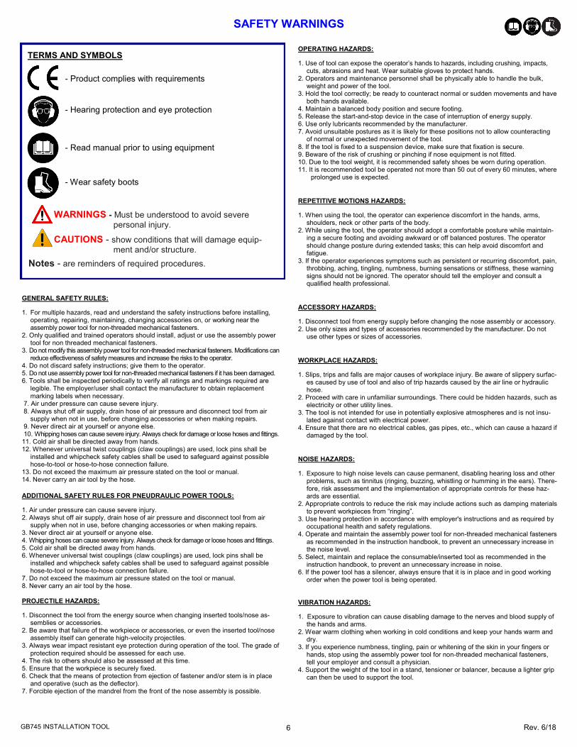
TERMS AND SYMBOLS
- Product complies with requirements
- Hearing protection and eye protection
WARNINGS - Must be understood to avoid severe
personal injury.
CAUTIONS - show conditions that will damage equip-
ment and/or structure.
Notes - are reminders of required procedures.
- Read manual prior to using equipment
- Wear safety boots

7 Rev. 6/18
GB745 INSTALLATION TOOL
PRINCIPLE OF OPERATION
Images may not reflect actual tool
RETURN Cycle
Piston Travel
Air Piston moves up
Piston Rod Assy moves up
Air exhaust
Pressurized Oil
Return Oil
Pressurized Air
Unpressurized Air
Air exhaust
Piston Rod Assy moves down
Air Piston moves down
PULL Cycle
Piston Travel
When the actuator lever assy is depressed, the pressurized air inside the tool is released allowing spring pressure to move the valve spool assy, causing the air to be redirected. The air is directed to the top side of the air piston assy, moving it in a downward direction. The air below the air piston assy is then directed through the valve sleeve and exhausted out of the bottom of tool. Simultaneously, the piston rod assy connected to the air piston assy is also moving down, forcing hydraulic oil up and into the front side of the head cylinder assy, causing the piston to move to the rear of the head cylinder assy. The oil from the rear of the head cylinder assy is directed to the top of the piston rod assy inside the power cylinder. The internal components of the attached nose assembly are also moving with the piston to start the fastener installation. When the fastener installation is completed, the actuator lever assy is released. Air pressure is then built up inside of the handle assy causing the valve spool assy to return to its original position and reversing the sequence.
Air exhaust
8 Rev. 6/18
GB745 INSTALLATION TOOL
HOW TO SET-UP THE GB745
WARNING: Only qualified and trained operators should install, adjust or use the assembly power tool for non-threaded mechanical fasteners.
WARNING: Operator MUST read and understand all warnings and cautions.
WARNING: It is required that eye protection, hearing protection and safety boots be worn at all times while handling this
equipment.
WARNING: The users or the user’s employer should assess specific risks that could be present as a result after each use based on their application.
● Be sure there is adequate clearance for tool and operator's hands before proceeding. Keep fingers clear of any moving parts. Keep fingers clear from fasteners and installed materials. Severe personal injury may result.
● Verify the air lines and/or hydraulic hoses are not a trip hazard.
● Ensure that there are no electrical cables, gas pipes, etc., which can cause a hazard if damaged by the tool.
WARNING: Do not pull rivet in the air. Personal injury from fastener ejecting may occur.
WARNING: Air is exhausted from the bottom of the tool. Direct bottom of the tool (exhausted air) away from operator, other
persons working in the vicinity, foreign matter and liquid.
WARNING: Do not carry from hoses or use as a hammer.
WARNING: Do not use in explosive atmosphere.
WARNING: Ensure air hose is securely connected to avoid possible hose whipping.
WARNING: Always disconnect air supply when tool is not in use to prevent accidental start-up.
WARNING: Be sure there is adequate clearance for tool and operator hands.
CAUTION: Do not use beyond the design intent.
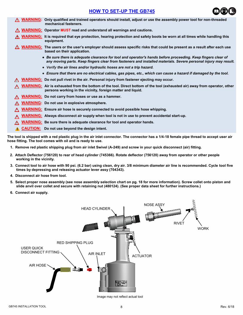
The tool is shipped with a red plastic plug in the air inlet connector. The connector has a 1/4-18 female pipe thread to accept user air hose fitting. The tool comes with oil and is ready to use.
1. Remove red plastic shipping plug from air inlet Swivel (A-249) and screw in your quick disconnect (air) fitting.
2. Attach Deflector (756120) to rear of head cylinder (745366). Rotate deflector (756120) away from operator or other people working in the vicinity.
3. Connect tool to air hose with 90 psi. (6.2 bar) using clean, dry air. 3/8 minimum diameter air line is recommended. Cycle tool five times by depressing and releasing actuator lever assy (704343).
4. Disconnect air hose from tool.
5. Select proper nose assembly (see nose assembly selection chart on pg. 18 for more information). Screw collet onto piston and slide anvil over collet and secure with retaining nut (480124). (See proper data sheet for further instructions.)
6. Connect air supply.
AIR HOSE
USER QUICK DISCONNECT FITTING
RED SHIPPING PLUG
AIR INLET
HEAD CYLINDER NOSE ASSY
RIVET
WORK
ACTUATOR
Image may not reflect actual tool

9 Rev. 6/18
GB745 INSTALLATION TOOL
HOW TO USE THE GB745
Lockbolts
#1. Insert fastener through the work piece.
#2. Slide collar over fastener.
#3. Insert fastener into nose assembly.
#4. Press actuator to start cycle. #5. Release actuator as soon as fastener breaks. #6. Repeat steps 1-5.
Blind Fasteners 1. Insert fastener.
2. Insert rivet into nose assembly. 3. Press actuator to start cycle. 4. Release actuator as soon as fastener breaks.
5. Repeat steps 1-4.
Images may not reflect actual tool or fastener
WARNING: Only qualified and trained operators should install, adjust or use the assembly power tool for non-threaded mechanical fasteners.
WARNING: Operator MUST read and understand all warnings and cautions.
WARNING: It is required that eye protection, hearing protection and safety boots be worn at all times while handling this
equipment.
WARNING: The users or the user’s employer should assess specific risks that could be present as a result after each use based on their application.
● Be sure there is adequate clearance for tool and operator's hands before proceeding. Keep fingers clear of any moving parts. Keep fingers clear from fasteners and installed materials. Severe personal injury may result.
● Verify the air lines and/or hydraulic hoses are not a trip hazard.
● Ensure that there are no electrical cables, gas pipes, etc., which can cause a hazard if damaged by the tool.
WARNING: Do not pull rivet in the air. Personal injury from fastener ejecting may occur.
WARNING: Air is exhausted from the bottom of the tool. Direct bottom of the tool (exhausted air) away from operator, other
persons working in the vicinity, foreign matter and liquid.
WARNING: Do not carry from hoses or use as a hammer.
WARNING: Do not use in explosive atmosphere.
WARNING: Ensure air hose is securely connected to avoid possible hose whipping.
WARNING: Always disconnect air supply when tool is not in use to prevent accidental start-up.
WARNING: Be sure there is adequate clearance for tool and operator hands.
CAUTION: Do not use beyond the design intent.

10 Rev. 6/18
GB745 INSTALLATION TOOL
TORQUE SPECIFICATIONS
Button Head Cap Screws (402479) = 40 inch lbs. Packing Plug (744118) = 45 foot lbs. Flexlock Nut (400559) = 40 inch lbs. End Cap (745816) = 45 foot lbs. Button Head Cap Screws (402482) = 35-40 inch lbs. (Do NOT over-tighten)
DAILY MAINTENANCE
WARNING: Tool must be maintained in a safe working condition at all times and examined on a daily basis for damage or wear. Any repair should be done by qualified personnel trained on Gage Bilt procedures.
WARNING: Excessive contact with hydraulic oil and lubricants should be avoided.
WARNING: Maintenance personnel MUST read and understand all warnings and cautions.
WARNING: Disconnect tool from its power source before performing maintenance, cleaning or when replacing worn or damaged components. Severe personal injury may occur if power source is not disconnected.
WARNING: Read SDS documents for all applicable materials.
CLEANING AND LUBRICATING PROCEDURE
Image may not reflect actual tool
Daily cleaning and lubrication of nose assembly will greatly reduce downtime and increase life of components. Using sewing machine oil, or an equivalent cleaner/lubricant, follow instructions below.
Note:
Dispose of hydraulic oil in accordance with manufacture safety datasheet.
All tool materials are recyclable except rubber o’rings, seals and wipers.
The performance of any tool depends upon good maintenance practices. Following these minimal requirements daily will extend the life of your tool.
*Only use a clean dry air supply set at 90-100 p.s.i. (6.2-6.9 bar) Max. equipped with a filter-regulator to prevent wear.
* Check tool and nose assembly for damage. (Replace/Repair if necessary). See Overhaul (pgs. 13 - 15) for tool repair.
* Inspect hoses and couplings for wear, damage and leaks. (Replace/Repair if necessary).
* Verify that hydraulic hose fittings and couplings, air and electrical connections are secure. Tighten, Replace or Repair if necessary
* Cycle the tool several times to assure there are no leaks during use.
* Keep hydraulic system free of dirt.
* Proper care by operators is necessary in maintaining full productivity and reducing downtime.
* Keep nose assemblies, especially jaws, clean and free of chips and debris. Lube jaws and collet surfaces that jaws ride on with light machine oil on a daily basis.
* All Screwed End Caps, Base Covers, Air Fittings, Air Actuators, Screws and Nose Assemblies are to be examined at the end of each working shift to check that they are secure.
* For a complete overhaul, service tool kit (GB745TK) is recommended (see overhaul pgs. 13,14 & 15).
WEEKLY MAINTENANCE
Keep the hydraulic system full (only use Dexron III or equivalent) and free of air by using the air bleeder assy (704153) on a weekly basis or as needed. (See Filling and Bleeding procedure pgs. 11-12).
SEE TROUBLESHOOTING (PG. 13) AND OVERHAUL (PG. 13 - 15) FOR FURTHER GUIDANCE.
LUBRICATING
Lubricate nose assy after each cleaning and as often as needed.
1. Disconnect tool vacuum line (if equipped). 2. Point nose assembly into oil as shown. 3. Cycle tool 8-10 times and wipe dry.
CLEANING
Clean nose assy daily or as often as needed.
1. Dip into mineral spirits or similar solvent to clean jaws and wash away metal chips and debris. DO NOT allow jaws to come in contact with other solvents. DO NOT let jaws soak. Dry jaws immediately.
2. Disassemble nose assy and use a sharp “pick” to remove embedded particles from grooves of jaws.
11 Rev. 6/18
GB745 INSTALLATION TOOL
FILLING & BLEEDING PROCEDURE
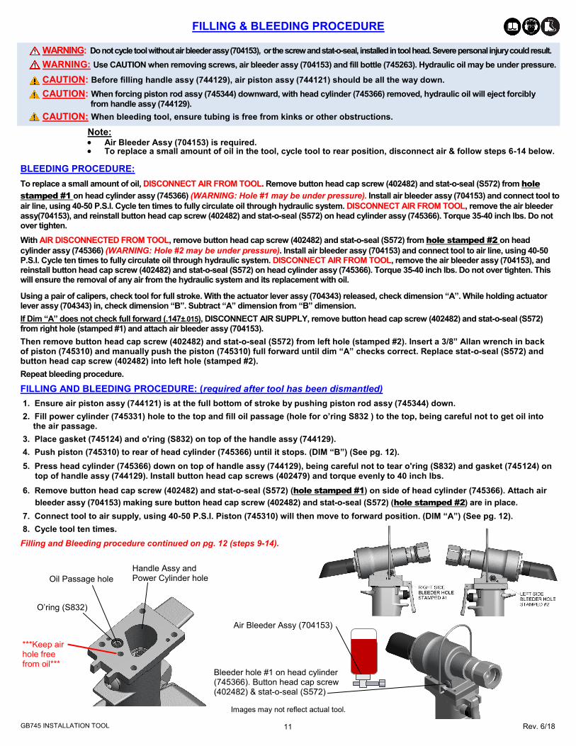
Images may not reflect actual tool.
Bleeder hole #1 on head cylinder (745366). Button head cap screw (402482) & stat-o-seal (S572)
Air Bleeder Assy (704153)
WARNING: Do not cycle tool without air bleeder assy (704153), or the screw and stat-o-seal, installed in tool head. Severe personal injury could result.
WARNING: Use CAUTION when removing screws, air bleeder assy (704153) and fill bottle (745263). Hydraulic oil may be under pressure.
CAUTION: Before filling handle assy (744129), air piston assy (744121) should be all the way down.
CAUTION: When forcing piston rod assy (745344) downward, with head cylinder (745366) removed, hydraulic oil will eject forcibly
from handle assy (744129).
CAUTION: When bleeding tool, ensure tubing is free from kinks or other obstructions.
Note:
Air Bleeder Assy (704153) is required. To replace a small amount of oil in the tool, cycle tool to rear position, disconnect air & follow steps 6-14 below.
Oil Passage hole
O’ring (S832)
Handle Assy and Power Cylinder hole
***Keep air hole free from oil***
BLEEDING PROCEDURE:
To replace a small amount of oil, DISCONNECT AIR FROM TOOL. Remove button head cap screw (402482) and stat-o-seal (S572) from hole
stamped #1 on head cylinder assy (745366) (WARNING: Hole #1 may be under pressure). Install air bleeder assy (704153) and connect tool to
air line, using 40-50 P.S.I. Cycle ten times to fully circulate oil through hydraulic system. DISCONNECT AIR FROM TOOL, remove the air bleeder assy(704153), and reinstall button head cap screw (402482) and stat-o-seal (S572) on head cylinder assy (745366). Torque 35-40 inch lbs. Do not over tighten.
With AIR DISCONNECTED FROM TOOL, remove button head cap screw (402482) and stat-o-seal (S572) from hole stamped #2 on head
cylinder assy (745366) (WARNING: Hole #2 may be under pressure). Install air bleeder assy (704153) and connect tool to air line, using 40-50 P.S.I. Cycle ten times to fully circulate oil through hydraulic system. DISCONNECT AIR FROM TOOL, remove the air bleeder assy (704153), and reinstall button head cap screw (402482) and stat-o-seal (S572) on head cylinder assy (745366). Torque 35-40 inch lbs. Do not over tighten. This will ensure the removal of any air from the hydraulic system and its replacement with oil.
Using a pair of calipers, check tool for full stroke. With the actuator lever assy (704343) released, check dimension “A”. While holding actuator lever assy (704343) in, check dimension “B”. Subtract “A” dimension from “B” dimension.
If Dim “A” does not check full forward (.147±.015), DISCONNECT AIR SUPPLY, remove button head cap screw (402482) and stat-o-seal (S572) from right hole (stamped #1) and attach air bleeder assy (704153).
Then remove button head cap screw (402482) and stat-o-seal (S572) from left hole (stamped #2). Insert a 3/8” Allan wrench in back of piston (745310) and manually push the piston (745310) full forward until dim “A” checks correct. Replace stat-o-seal (S572) and button head cap screw (402482) into left hole (stamped #2).
Repeat bleeding procedure.
FILLING AND BLEEDING PROCEDURE: (required after tool has been dismantled)
1. Ensure air piston assy (744121) is at the full bottom of stroke by pushing piston rod assy (745344) down.
2. Fill power cylinder (745331) hole to the top and fill oil passage (hole for o’ring S832 ) to the top, being careful not to get oil into the air passage.
3. Place gasket (745124) and o'ring (S832) on top of the handle assy (744129).
4. Push piston (745310) to rear of head cylinder (745366) until it stops. (DIM “B”) (See pg. 12).
5. Press head cylinder (745366) down on top of handle assy (744129), being careful not to tear o'ring (S832) and gasket (745124) on top of handle assy (744129). Install button head cap screws (402479) and torque evenly to 40 inch lbs.
6. Remove button head cap screw (402482) and stat-o-seal (S572) (hole stamped #1) on side of head cylinder (745366). Attach air
bleeder assy (704153) making sure button head cap screw (402482) and stat-o-seal (S572) (hole stamped #2) are in place.
7. Connect tool to air supply, using 40-50 P.S.I. Piston (745310) will then move to forward position. (DIM “A”) (See pg. 12).
8. Cycle tool ten times.
Filling and Bleeding procedure continued on pg. 12 (steps 9-14).

12 Rev. 6/18
GB745 INSTALLATION TOOL
FILLING & BLEEDING PROCEDURE CONTINUED:
WARNING: Do not cycle tool without air bleeder assy (704153), or the screw and stat-o-seal, installed in tool head. Severe personal injury could result.
WARNING: Use CAUTION when removing screws, air bleeder assy (704153) and fill bottle (745263). Hydraulic oil may be under pressure.
CAUTION: Before filling handle assy (744129), air piston assy (744121) should be all the way down.
CAUTION: When forcing piston rod assy (745344) downward, with head cylinder (745366) removed, hydraulic oil will eject forcibly from handle assy (744129).
CAUTION: When bleeding tool, ensure tubing is free from kinks or other obstructions.
Image may not reflect actual tool.
Note:
Air Bleeder Assy (704153) is required. To replace a small amount of oil in the tool, cycle tool to rear position, disconnect air & follow steps 6-14 below.
9. Disconnect air supply, remove air bleeder assy (704153) and replace button head cap screw (402482) and stat-o-seal (S572) and torque to 35-40 inch lbs. Do not over tighten.
10. Carefully remove button head cap screw (402482) and stat-o-seal (S572) from hole stamped #2 (WARNING: Hole #2 may be under
pressure) and attach air bleeder assy (704153) to hole stamped #2.
11. Reconnect tool to air supply, using 40-50 P.S.I. Cycle tool ten times.
12. Remove air bleeder assy (704153) and replace button head cap screw (402482) and stat-o-seal (S572) to hole stamped #2 and torque to 35-40 inch lbs. Do not over tighten.
13. Connect tool to air supply using 40-50 P.S.I. and cycle tool ten times.
14. Using a pair of calipers, check tool for full stroke (.620”) (15.75 mm). With the actuator lever assy (704343) released, check dimension “A”. While holding actuator lever assy (704343) in, check dimension “B”. Subtract “A” dimension from “B” dimension.
If Dim “A” does not check full forward (.147±.015), DISCONNECT AIR SUPPLY, remove button head cap screw (402482) and stat-o-seal (S572) from right hole (stamped #1) and attach air bleeder assy (704153).
Then remove button head cap screw (402482) and stat-o-seal (S572) from left hole (stamped #2). Insert a 3/8” Allan wrench in back of piston (745310) and manually push the piston (745310) full forward until dim “A” checks correct. Replace stat-o-seal (S572) and button head cap screw (402482) into left hole (stamped #2).
The tool is now ready to repeat steps 8 - 14.
Air Bleeder Assy (704153)
Bleeder hole #2 on head cylinder (745366) Button head cap screw (402482) & stat-o-seal (S572)
13 Rev. 6/18
GB745 INSTALLATION TOOL
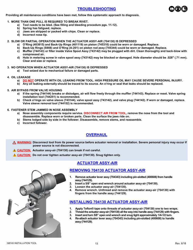
TROUBLESHOOTING
Providing all maintenance conditions have been met, follow this systematic approach to diagnosis. 1. MORE THAN ONE PULL IS REQUIRED TO BREAK RIVET.
a) Tool needs to be bled. (See filling and bleeding procedure pgs. 11-12). b) Spring has fatigued, replace. c) Jaws are stripped or packed with chips. Clean or replace. d) Incorrect nose tip.
2. SLOW OR PARTIAL OPERATION WHEN THE ACTUATOR ASSY-AIR (704130) IS DEPRESSED a) O’Ring (403815) and Back-Up Rings (401119) on piston (745310) could be worn or damaged. Replace.
b) Back-Up Rings (S908) and O’Ring (A-201) on piston rod assy (745344) could be worn or damaged. Replace. c) Muffler (744143) or filter inside Valve Spool Assy (743142) may be plugged with dirt. Clean thoroughly and back-blow with
compressed air. d) Hole in metering screw in valve spool assy (743142) may be blocked or damaged. Hole diameter should be .028" (.71 mm).
Clear and size or replace.
3. NO OPERATION WHEN ACTUATOR ASSY-AIR (704130) IS DEPRESSED a) Tool seized due to mechanical failure or damaged parts.
4. OIL LEAKAGE a) DO NOT OPERATE WITH OIL LEAKING FROM TOOL. HIGH PRESSURE OIL MAY CAUSE SEVERE PERSONAL INJURY. b) Any oil leaking externally should be traced to its source. An o'ring or seal that leaks should be replaced.
5. AIR BYPASS FROM VALVE HOUSING a) If the spring (744144) breaks or dislodges, air will flow freely through the muffler (744143). Replace or reset. Valve spring
installation tool (744251) is recommended. b) Check o'rings on valve sleeve (743144), valve spool assy (743142), and valve plug (744142). If worn or damaged, replace.
Valve sleeve removal tool (744152) is recommended.
6. FASTENER STEM JAMMED IN NOSE ASSEMBLY a) Nose assembly components require service. DISCONNECT AIR FROM TOOL, remove the nose from the tool and disassemble. Replace worn or broken parts. Clean the surface the jaws ride on. b) Stems lodged side by side in the follower. Disassemble, remove stems, and reassemble. c) Incorrect follower.
REMOVING 704130 ACTUATOR ASSY-AIR
1. Remove actuator lever assy (704343) including pin-slotted (400608) from handle assy (744129). 2. Insert a 5/8” open end wrench around actuator assy-air (704130). 3. Loosen the actuator assy-air (704130). 4. Remove wrench. Unthread and remove the actuator assy-air (704130) with fingers from the handle assy (744129).
INSTALLING 704130 ACTUATOR ASSY-AIR
1. Apply Teflon® tape onto threads of actuator assy-air (704130) one to two wraps. 2. Thread the actuator assy-air (704130) all the way into handle assy (744129) with fingers. 3. Insert and turn 5/8” open end wrench and snug tight approximately 1/4-1/2 turn. 4. Re-attach actuator lever assy (704343) including pin-slotted (400608) to handle assy (744129).
ACTUATOR ASSY-AIR
OVERHAUL
WARNING: Disconnect tool from its power source before actuator removal or installation. Severe personal injury may occur if power source is not disconnected.
CAUTION: Actuator assy-air (704130) can break if not careful.
CAUTION: Do not over tighten actuator assy-air (704130). Snug tighten only.
14 Rev. 6/18
GB745 INSTALLATION TOOL
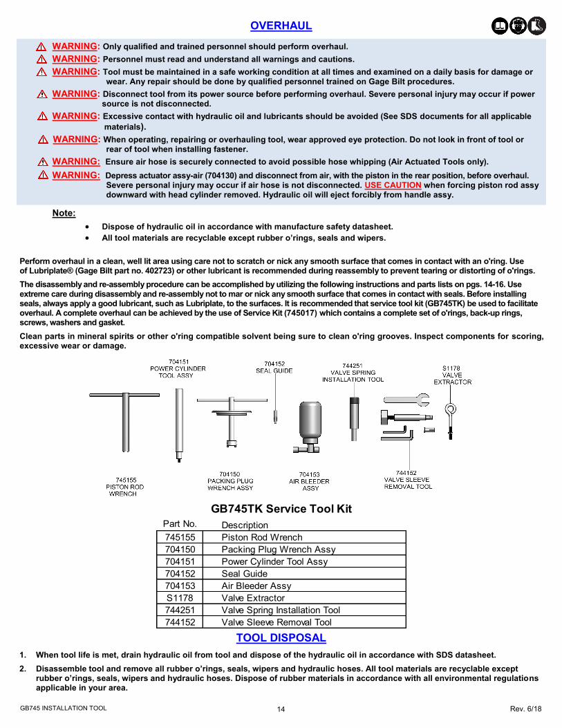
Part No. Description
745155 Piston Rod Wrench
704150 Packing Plug Wrench Assy
704151 Power Cylinder Tool Assy
704152 Seal Guide
704153 Air Bleeder Assy
S1178 Valve Extractor
744251 Valve Spring Installation Tool
744152 Valve Sleeve Removal Tool
GB745TK Service Tool Kit
OVERHAUL
WARNING: Only qualified and trained personnel should perform overhaul.
WARNING: Personnel must read and understand all warnings and cautions.
WARNING: Tool must be maintained in a safe working condition at all times and examined on a daily basis for damage or wear. Any repair should be done by qualified personnel trained on Gage Bilt procedures.
WARNING: Disconnect tool from its power source before performing overhaul. Severe personal injury may occur if power source is not disconnected.
WARNING: Excessive contact with hydraulic oil and lubricants should be avoided (See SDS documents for all applicable
materials).
WARNING: When operating, repairing or overhauling tool, wear approved eye protection. Do not look in front of tool or rear of tool when installing fastener.
WARNING: Ensure air hose is securely connected to avoid possible hose whipping (Air Actuated Tools only).
WARNING: Depress actuator assy-air (704130) and disconnect from air, with the piston in the rear position, before overhaul. Severe personal injury may occur if air hose is not disconnected. USE CAUTION when forcing piston rod assy downward with head cylinder removed. Hydraulic oil will eject forcibly from handle assy.
Perform overhaul in a clean, well lit area using care not to scratch or nick any smooth surface that comes in contact with an o'ring. Use of Lubriplate® (Gage Bilt part no. 402723) or other lubricant is recommended during reassembly to prevent tearing or distorting of o'rings.
The disassembly and re-assembly procedure can be accomplished by utilizing the following instructions and parts lists on pgs. 14-16. Use extreme care during disassembly and re-assembly not to mar or nick any smooth surface that comes in contact with seals. Before installing seals, always apply a good lubricant, such as Lubriplate, to the surfaces. It is recommended that service tool kit (GB745TK) be used to facilitate overhaul. A complete overhaul can be achieved by the use of Service Kit (745017) which contains a complete set of o'rings, back-up rings, screws, washers and gasket.
Clean parts in mineral spirits or other o'ring compatible solvent being sure to clean o'ring grooves. Inspect components for scoring, excessive wear or damage.
TOOL DISPOSAL
1. When tool life is met, drain hydraulic oil from tool and dispose of the hydraulic oil in accordance with SDS datasheet.
2. Disassemble tool and remove all rubber o’rings, seals, wipers and hydraulic hoses. All tool materials are recyclable except rubber o’rings, seals, wipers and hydraulic hoses. Dispose of rubber materials in accordance with all environmental regulations applicable in your area.
Note:
Dispose of hydraulic oil in accordance with manufacture safety datasheet.
All tool materials are recyclable except rubber o’rings, seals and wipers.
15 Rev. 6/18
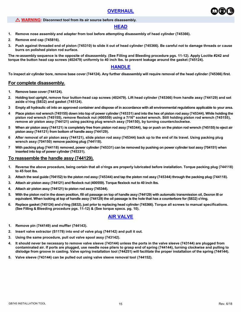
GB745 INSTALLATION TOOL
WARNING: Disconnect tool from its air source before disassembly.
OVERHAUL
1. Remove nose assembly and adapter from tool before attempting disassembly of head cylinder (745366).
2. Remove end cap (745816).
3. Push against threaded end of piston (745310) to slide it out of head cylinder (745366). Be careful not to damage threads or cause burrs on polished piston rod surface.
The re-assembly sequence is the opposite of disassembly. (See Filling and Bleeding procedure pgs. 11-12). Apply Loctite #242 and torque the button head cap screws (402479) uniformly to 40 inch lbs. to prevent leakage around the gasket (745124).
HEAD
HANDLE
To inspect air cylinder bore, remove base cover (744124). Any further disassembly will require removal of the head cylinder (745366) first.
For complete disassembly. 1. Remove base cover (744124).
2. Holding tool upright, remove four button-head cap screws (402479). Lift head cylinder (745366) from handle assy (744129) and set aside o'ring (S832) and gasket (745124).
3 Empty all hydraulic oil into an approved container and dispose of in accordance with all environmental regulations applicable to your area.
4 Place piston rod wrench (745155) down into top of power cylinder (745331) and into the hex of piston rod assy (745344). While holding the piston rod wrench (745155), remove flexlock nut (400559) using a 7/16" socket wrench. Still holding piston rod wrench (745155), remove air piston assy (744121) using packing plug wrench assy (704150), by turning counterclockwise.
5 When air piston assy (744121) is completely free from piston rod assy (745344), tap or push on the piston rod wrench (745155) to eject air piston assy (744121) from bottom of handle assy (744129).
6 After removal of air piston assy (744121), slide piston rod assy (745344) back up to the end of its travel. Using packing plug wrench assy (704150) remove packing plug (744118).
7 With packing plug (744118) removed, power cylinder (745331) can be removed by pushing on power cylinder tool assy (704151) when inserted into top of power cylinder (745331).
To reassemble the handle assy (744129). 1. Reverse the above procedure, being certain that all o'rings are properly lubricated before installation. Torque packing plug (744118)
to 45 foot lbs.
2. Attach the seal guide (704152) to the piston rod assy (745344) and tap the piston rod assy (745344) through the packing plug (744118).
3. Attach air piston assy (744121) and flexlock nut (400559). Torque flexlock nut to 40 inch lbs.
4. Attach air piston assy (744121) to piston rod assy (745344).
5. With the piston rod in the down position, fill oil passage on top of handle assy (744129) with automatic transmission oil, Dexron III or equivalent. When looking at top of handle assy (744129) the oil passage is the hole that has a counterbore for (S832) o'ring.
6. Replace gasket (745124) and o'ring (S832), just prior to replacing head cylinder (745366). Torque all screws to manual specifications. (See Filling & Bleeding procedure pgs. 11-12) & (See torque specs. pg. 10).
AIR VALVE
1. Remove pin (744149) and muffler (744143).
2. Insert valve extractor (S1178) into end of valve plug (744142) and pull it out.
3. Using the same procedure, pull out valve spool assy (743142).
4. It should never be necessary to remove valve sleeve (743144) unless the ports in the valve sleeve (743144) are plugged from contaminated air. If ports are plugged, use needle nose pliers to grasp end of spring (744144), turning clockwise and pulling to dislodge from groove in casting. Valve spring installation tool (744251) will facilitate the proper installation of the spring (744144).
5. Valve sleeve (743144) can be pulled out using valve sleeve removal tool (744152).

16 Rev. 6/18
GB745 INSTALLATION TOOL
PARTS LIST
WARNING:
This tool incorporates a patented hydraulic relief valve. When overhauling tool, o’ring (A-287), back-up ring (401101), retaining ring (400936) and spring (50806) must be replaced. Failure to do so could result in SEVERE PERSONAL INJURY!
17 Rev. 6/18
GB745 INSTALLATION TOOL
FIRST AID MEASURES Eye: No specific first aid measures are required. As a precaution, remove contact lenses, if worn, and flush eyes with water. Skin: No specific first aid measures are required. As a precaution, remove clothing and shoes if contaminated. To remove the material from skin, use soap and water. Discard contaminated clothing and shoes or thoroughly clean before reuse. Ingestion: No specific first aid measures are required. Do not induce vomiting. As a precaution, get medical advice. Inhalation: No specific first aid measures are required. If exposed to excessive levels of material in the air, move the exposed person to fresh air. Get medical attention if coughing or respiratory discomfort occurs. Note to Physicians: In an accident involving high-pressure equipment, this product may be injected under the skin. Such an accident may result in a small, sometimes bloodless, puncture wound. However, because of its driving force, material injected into a fingertip can be deposited into the palm of the hand. Within 24 hours, there is usually a great deal of swelling, discoloration, and intense throbbing pain. Immediate treatment at a surgical emergency center is recommended. FIRE Leaks/ruptures in high pressure system using materials of this type can create a fire hazard when in the vicinity of ignition sources (eg. open flame, pilot lights, sparks, or electric arcs). FLAMMABLE PROPERTIES: Flashpoint: (Cleveland Open Cup) 178 °C (352 °F) Minimum EXTINGUISHING MEDIA: Use water fog, foam, dry chemical or carbon dioxide (CO2) to extinguish flames. PROTECTION OF FIRE FIGHTERS: Fire Fighting Instructions: This material will burn although it is not easily ignited. See Section 7 for proper handling and storage. For fires involving this material, do not enter any enclosed or confined fire space without proper protective equipment, including self-contained breathing apparatus. Combustion Products: Highly dependent on combustion conditions. A complex mixture of airborne solids, liquids, and gases including carbon monoxide, carbon dioxide, and unidentified organic compounds will be evolved when this material undergoes combustion. ACCIDENTAL RELEASE MEASURES Protective Measures: Eliminate all sources of ignition in vicinity of spilled material. Spill Management: Stop the source of the release if you can do it without risk. Contain release to prevent further contamination of soil, surface water or groundwater. Clean up spill as soon as possible. Use appropriate techniques such as applying non-combustible absorbent materials or pumping. Where feasible and appropriate, remove contaminated soil. Place contaminated materials in disposable containers and dispose of in a manner consistent with applicable regulations. ECOLOGICAL INFORMATION Waste disposal: In accordance with all environmental regulations applicable to your area.
Spillage: Prevent entry into drains, sewers and water course. Soak up with diatomaceous earth or other inert material. Store in appropriate container for disposal. Ecotoxocity: This material is expected to be harmful to aquatic organisms and may cause long-term adverse effects in the aquatic environment. The ecotoxicity hazard is based on an evaluation of data for the components or a similar material. HANDLING Precautionary Measures: DO NOT USE IN HIGH PRESSURE SYSTEMS in the vicinity of flames, sparks and hot surfaces. Use only in well ventilated areas. Keep container closed. Keep out of the reach of children. General Handling Information: Avoid contaminating soil or releasing this material into sewage and drainage systems and bodies of water. Static Hazard: Electrostatic charge may accumulate and create a hazardous condition when handling this material. To minimize this hazard, bonding and grounding may be necessary but may not, by themselves, be sufficient. Review all operations which have the potential of generating and accumulating an electrostatic charge and/or a flammable atmosphere (including tank and container filling, splash filling, tank cleaning, sampling, gauging, switch loading, filtering, mixing, agitation, and vacuum truck operations) and use appropriate mitigating procedures. DISPOSAL CONSIDERATIONS Use material for its intended purpose or recycle if possible. Oil collection services are available for used oil recycling or disposal. Place contaminated materials in containers and dispose of in a manner consistent with applicable regulations.
DEXRON® III OIL SAFETY DATA

18 Rev. 6/18
GB745 INSTALLATION TOOL
FASTENER DIA.1/8 4A-745C-23 4A-745C-48 4A-752B-43OS 5
5/32 5A-745C-23 5A-745C-48 5A-752B-43OS 5
3/16 6A-745B-23 6A-745B-48 6A-752B-43OS 5
1/4 SMLS08-755-23 SMLS08-755-48 SMLS08-204D-27OS SMLS08-204D-37OS
13/64 ASP06-745C-23 ASP06-745C-48 ASP06-752B-43OS 5
17/64 ASP08-745B-23 ASP08-745B-48 ASP08-752B-43OS 5
21/64 ASP10-755-23 ASP10-755-48 ASP10-204D-27OS ASP10-204D-37OS
BOM®
AVBOLT®1/4 BOM08-755A-23
3/16 NAS06-2581-12 NAS06-204C-25OS NAS06-204D-30OS
NAS06-2581-23 NAS06-2581-48 NAS06-204C-34OS
1/4 NAS08-2581-12 NAS08-204C-25OS NAS08-204D-30OS
NAS08-2581-23 NAS08-2581-48 NAS08-205A-31 NAS08-204C-34OS
5/16 1 LB10-745C-26 NAS10-2581-48 NAS10-205D-31
3/8 2 LB12-756-26 NAS12-756-48 NAS12-205A-31
CONTAINER BOLT 3/8 HT12-756-23
FLOOR BOLT 5/16 FT10-353A-28
5/32 LGP05-2581-12 LGP05-204C-25OS LGP05-204C-30OS
LGP05-2581-23 LGP05-2581-48 LGP05-204C-34OS
3/16 LGP06-2581-12 LGP06-204C-25OS LGP06-204D-30OS
LGP06-2581-23 LGP06-2581-48 LGP06-204C-34OS
7/32 LGP07-2581-12 LGP07-204C-25OS LGP07-204D-30OS
LGP07-755-23 LGP07-755-48 LGP07-204C-34OS
1/4 LGP08-2581-12 LGP08-204C-25OS LGP08-204D-30OS
LGP08-2581-23 LGP08-2581-48 LGP08-204C-34OS LGP08-205A-31
5/16 LGP10-2581-12
LGP10-2581-23 LGP10-2581-48 LGP10-205D-31
4mm MLGP4-2581-12 MLGP4-204C-25OS MLGP4-204C-30OS
MLGP4-2581-23 MLGP4-2581-48 MLGP4-204C-34OS
5mm MLGP5-2581-12 MLGP5-204C-25OS MLGP5-204D-30OS
MLGP5-2581-23 MLGP5-2581-48 MLGP5-204C-34OS
6mm MLGP6-2581-12 MLGP6-204C-25OS MLGP6-204D-30OS
MLGP6-2581-23 MLGP6-2581-48 MLGP6-204C-34OS
8mm MLGP8-2581-12 MLGP8-204C-25OS MLGP8-204C-30OS
MLGP8-2581-23 MLGP8-2581-48 MLGP8-204C-34OS MLGP8-205A-31
5/32 NASS05-2581-12 NAST05-2581-12 NASS05-204C-25O NAST05-204C-25O
NASS05-2581-23 NAST05-2581-23 NASS05-204C-30O NAST05-204C-30O
NASS05-2581-48 NAST05-2581-48 NASS05-204C-34O NAST05-204C-34O
3/16 NAS06-2581-12 NAS06-204C-25OS NAS06-204D-30OS
NAS06-2581-23 NAS06-2581-48 NAS06-204C-34OS
1/4 NAS08-2581-12 NAS08-204C-25OS NAS08-204D-30OS
NAS08-2581-23 NAS08-2581-48 NAS08-204C-34OS NAS08-205A-31
5/16 NAS10-2581-12 NAS10-205D-31
NAS10-2581-23 NAS10-2581-48
3/8 1 NAS12-745B-12 NAS12-205A-31
NAS12-756-26 NAS12-756-48
4mm MGP4-2581-23 MGP4-2581-48 MGP4-204C-25OS MGP4-204C-30OS
MGP4-204C-34OS
5mm MGP5-2581-23 MGP5-2581-48 MGP5-204C-25OS MGP5-204D-30OS
MGP5-204C-34OS
6mm MGP6-2581-23 MGP6-2581-48 MGP6-204C-25OS MGP6-204D-30OS
MGP6-204C-34OS
8mm MGP8-2581-23 MGP8-2581-48
3/16 MG06-745-48
1/4 MG08-745-48
1/8
5/32
3/16
1/8
5/32
3/16
NAS1900 S & U SERIES BLIND
RIVET WITH DRIVE WASHER1/4 08MAX-745B-23 08MAX-745B-48 08MAX-204D-27OS 08MAX-204D-37OS
5/32 SB05-745C-23 SB05-745C-48 SB05-752A-43OS 5
3/16 SB06-745B-23 SB06-745B-48 SB06-204D-27OS SB06-204D-37OS
1/4 SB08-755-23 SB08-755-48 SB08-204D-27OS SB08-204D-37OS
5/32 UBB05-745C-23 UBB05-745C-48 UBB05-752B-43OS 5
3/16 UBB06-745B-23 UBB06-745B-48 UBB06-204D-27OS UBB06-204D-37OS
1/4 UBB08-755-23 UBB08-755-48 UBB08-204D-27OS UBB08-204D-37OS
5/32 UAB568-713-21 3 UAB568-713-61 3 UAB05-752B-43OS 5
3/16 UAB06-752B-43OS 5
1/4 UAB08-204D-27OS UAB08-204D-37OS
1/8 SMLS04-745C-23 SMLS04-745C-48 SMLS04-752B-43OS 5
5/32 SMLS05-745C-23 SMLS05-745C-48 SMLS05-752B-43OS 5
3/16 SMLS06-745B-23 SMLS06-745B-48 SMLS06-752B-43OS 5
1/4 SMLS08-755-23 SMLS08-755-48 SMLS08-204D-27OS SMLS08-204D-37OS
EXTENDS FROM THE TOOL I.E. -20 = 2.0 INCHES Rev. 2/18
*OFFSET
A' CODE
NAS1398 & NAS1399 'A'
STRAIGHT
COMMERCIAL LOCKBOLTS
C6L®
AVDELOK®
1/4
ASP®
2 ASP® & ASP PF
ASP FF & ASP F
ASP-LC & MAF
MULTI-GRIP LOCKBOLT
456MAX-731-43OS 4
BLIND BOLT (SINGLE ACTION)
WITH DRIVE WASHER
M S90353S & U / M S90354S & U
M S21140S & U / M S21141S & U
M AXI-BOLT®, BACB30YY, YU, & YT
456MAX-751-23 4
CHERRYMAX®,
CHERRYMAX® 'AB',
BACR15FR/FP, BACR15GF/GK
456MAX-751A-61 4
456MAX-731-43OS 1,4
BLIND RIVET (SINGLE ACTION)
WITH OR W/OUT DRIVE
WASHER
NAS1900 S & U SERIES
MBC® LOCK CREATOR
NAS1719X(L), NAS1720X(L)
NAS1721X(L)
456MAX-751A-61 1,4
NOTE: THE LAST 2 DIGITS OF THE NOSE ASSEMBLY REPRESENTS THE LENGTH THE NOSE
2) GENERAL PURPOSE LOCKBOLTS ONLY.
4) INSTALLS 1/8, 5/32, & 3/16 DIAMETERS.
5) ALL OFFSET 713 AND 752 SERIES NOSES REQUIRE 745751 ADAPTER.
3) INSTALLS 5/32, 3/16 & 1/4 DIAMETERS.
PT/MS/9SP
MS20600 & MS20601
GAGE BILT CERTIFIES THE GB745 WILL INSTALL THE ABOVE FASTENERS
PT08-745B-48
1) ALL MATERIALS EXCEPT TITANIUM & STAINLESS.
*ALL OFFSET 204 SERIES NOSES REQUIRE 353204 ADAPTER, & ALL OFFSET 205 SERIES NOSES REQUIRE 353205 ADAPTER.
EN6122 & UAB130-EU
EN6127 & UAB6127-EU
EN6128 & UAB100-EU
EN6129 & UABP-EU
BLIND BOLT (SINGLE ACTION)
WITH OR W/OUT DRIVE
WASHER
M S90353S & U / M S90354S & U
M S21140S & U / M S21141S & U
M AXI-BOLT®, BACB30YY, YU, & YT
456MAX-751-23 1,4
ASP®, BOM ®, C6L®, LGP®,M LGP®, M GP® AND GP® ARE REGISTERED TRADEM ARKS OF ARCONIC INC. AVBOLT® AND AVDELOK® ARE
REGISTERED TRADEM ARKS OF AVDEL UK LIM ITED. M AXI-BOLT® AND M BC® ARE REGISTERED TRADEM ARKS OF CHERRY AEROSPACE
FASTENERS.
LGP®
LGPL2SC-VLGPL18SC-V
LGPL4SC-VLGPL2SP-VLGPL4SP-VLGPL8SC-V
LGPL9SC-VLGPL9SP-VBACB31N
BACB30VMBACB30XT
ABS0548BACB30VNASNA2392BACB30WD
BACB30WBBACB30VYBACB31P
NAS and GP®SHEAR/TENSION
LOCKBOLTS
BACB30UABACB30UB
BACB30GXBACB30GPBACB30GY
BACB30TYBACB30TZ
BACB30DYBACB30DXBACB30GO
BACB30GW
MLGP®(MILLIMETER)
LOCKBOLT
MGP®(MILLIMETER)
LOCKBOLT
Gage Bilt also supplies pin & collar swage inspection gages to certify correct swage
installation. (Sold Separately)
ACCESSORIES
NOSE ASSEMBLY SELECTION CHART
Adapter Assy #353204
Adapts all offset 204 series noses (Sold Separately)
Adapter Assy #353205
Adapts all offset 205 series noses. (Sold Separately)
Adapter Assy #745751
Adapts all offset 713 and 752 series noses (Sold Separately)
Grip Gage #269G3 For CHERRYMAX® and CHERRYLOCK® rivets
(Sold Separately)
Grip Gage #GB105093 For NAS LOCKBOLTS and blind fasteners
(Sold Separately)
STRAIGHT (Sold Separately)
OFFSET (Sold Separately)

19 Rev. 6/18
GB745 INSTALLATION TOOL
This page intentionally left blank
20 Rev. 6/18
GB745 INSTALLATION TOOL
CHERRYMAX® AND CHERRYLOCK® ARE REGISTERED TRADEMARKS OF CHERRY AEROSPACE FASTENERS. DEXRON® IS A REGISTERED TRADEMARK OF GENERAL MOTORS CORPORATION. LUBRIPLATE® IS A REGISTERED TRADEMARK OF FISKE BROTHERS REFINING CO. LOCTITE® IS A REGISTERED TRADEMARK OF HENKEL CORPORATION. MAGNA-GRIP® IS A REGISTERED TRADEMARK OF ARCONIC INC.
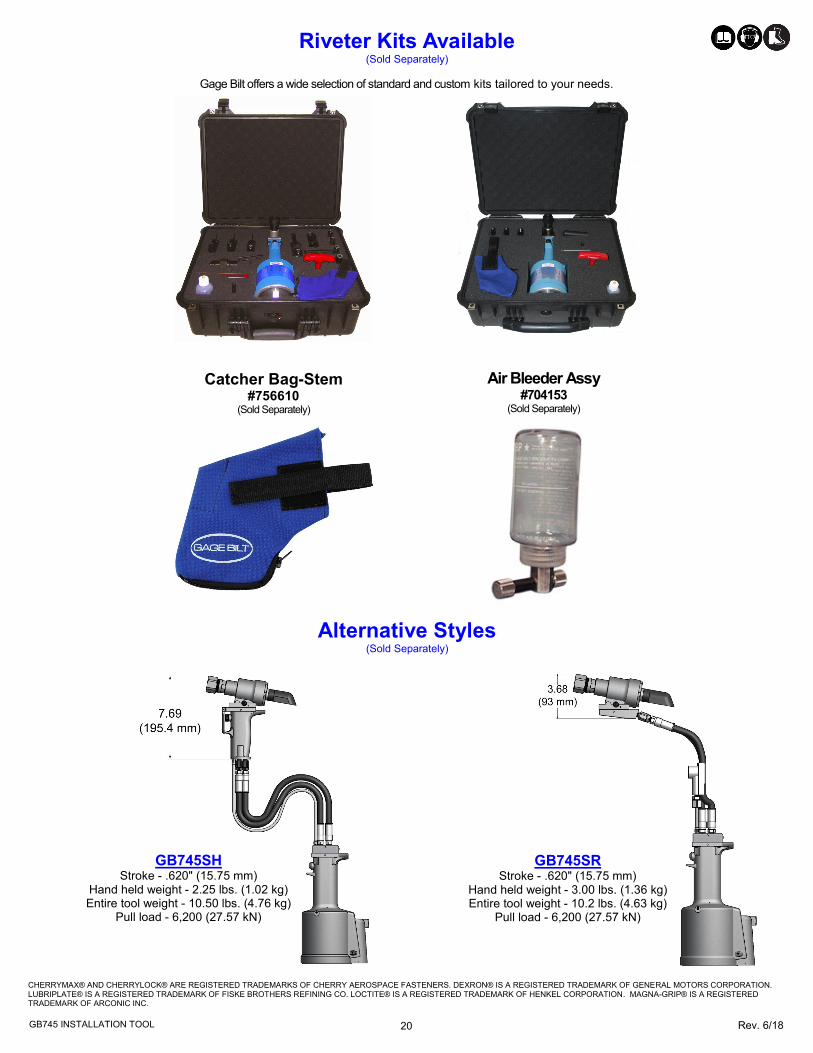
Air Bleeder Assy #704153
(Sold Separately)
Catcher Bag-Stem #756610
(Sold Separately)
Riveter Kits Available (Sold Separately)
Alternative Styles (Sold Separately)
GB745SH Stroke - .620" (15.75 mm)
Hand held weight - 2.25 lbs. (1.02 kg) Entire tool weight - 10.50 lbs. (4.76 kg)
Pull load - 6,200 (27.57 kN)
GB745SR Stroke - .620" (15.75 mm)
Hand held weight - 3.00 lbs. (1.36 kg) Entire tool weight - 10.2 lbs. (4.63 kg)
Pull load - 6,200 (27.57 kN)
Gage Bilt offers a wide selection of standard and custom kits tailored to your needs.