Embed Size (px)
Citation preview

Original Guide
OPERATION MANUAL
PART І
Installation of the Road Blocker of
RB392 series
(Boom Barrier "Optimus")

2
CONTENTS
1. General guidelines ...................................................................................................................
2. Product description ..................................................................................................................
3. Purpose ....................................................................................................................................
4.Technical features .....................................................................................................................
5.Product specification ................................................................................................................
6.Boom Barrier installation .........................................................................................................
7. Boom Barrier connection to control unit .................................................................................
8. Precommissioning ...................................................................................................................
9. Operation regulations ..............................................................................................................
10. Warranty liabilities ................................................................................................................
11. Notes......................................................................................................................................
3
6
7
8
10
12
21
22
24
28
29
The Manual is provided for joint use with the Operation Manual. Part II. Wiring and
Operation of the Road Blockers of RB series
The following abbreviation are used in this Manual:
M - Maintenance;;
R.s.l. - Road surface level (reference point 0.000).

3
In case of improper operation and noncompliance with requirements of instruction
manuals the Boom Barrier may constitute a danger to life and health of people by
presence of increased voltage in electric circuits and movable parts!
The Company "TiSO" does its best to provide surety and accuracy of this Manual and reflect
substantial design modifications. Continuous improvement may cause little differences between
the equipment to be supplied and the description herein.
The Manual to be kept for future use.
Operating equipment to be beyond the reach children and outsiders. The manufacturer shall
not be liable for violation of safety rules.
Any actions that are not explicitly specified in this Manual are forbidden.
The Manual to be scrutinized prior to the equipment installation and operation
to ensure safety of people. Safety is not ensured in case of improper operation
or use.
The personnel servicing operating electrical installations or performing their
adjustment, wiring, repair, maintenance and installation to be trained to handle
the relevant model! Training to be performed by the product manufacturer or
product manufacturer's representatives!
1. GENERAL WARNINGS AND PRECAUTIONS
4
1.1. Instructions to installer:
1. The equipment installation instructions to be complied with for the purpose of
safety.
2. The Boom Barrier to be installed according to the code of practice in compliance
with safety regulations for installation in accordance with the Standards EN 12453 and EN
12445.
3. The equipment to be installed when it is deenergized.
4. Packing materials are subject to disposal according to the applicable standards.
5. The Boom Barrier installation procedure, specified in the Manual, to be strictly
observed.
6. When faults or defects are detected, the Supplier's service department shall be
referred to;
7. The installer shall provide the user with the required information on operation of the
system in manual mode in case of emergency;;
8.The manufacturer shall not be liable for the equipment operation in the following
events:
- noncompliance with installation procedure;
- use of nonstandard materials and components;
- performance of work by unqualified personnel.
9.The manufacturer shall not be liable for compliance with safety measures during
installation of equipment by the personnel outside the Company's service department.
It is forbidden to modify the equipment configuration and to use materials
and components being outside the scope of delivery and not specified by
this Manual.
It is forbidden to install the equipment during thunderstorm, heavy rain or
snowfall, in explosive environment and obscured conditions.
The Boom Barrier to be installed, connected and precommissioned by qualified
professionals.

5
1.2. Instructions to user:
1. The operation regulations, prescribed by this Manual, to be strictly observed.
2. No modifications of the equipment components to be made.
3. The equipment to be used for intended purposes, specified by the manufacturer.
4. Don't try to repair or adjust the Road Barrier on your own. The relevant service
department shall be referred to. Breaking of seals shall cancel the manufacturer's warranty
liabilities.
5. The Boom Barrier control units (panels) to be beyond the reach of outsiders.
6. The Company "TiSO" shall not be liable for improper operation of equipment and
violation of safety measures by the user.
The relevant safety devices (Standard EN 12978) to be installed in dangerous areas to
protect against hazards related to mechanical movement of gate leaves (crushing, pinching
or cutting hazards).
Make sure of availability of the
plate with manufacturer's details:
The Boom Barrier must be installed, precommissioned and serviced by
certified professionals having the relevant qualification and being familiar
with the product design and instruction manuals:
- Boom Barrier installation and operation manual (Part І, Part ІІ);
- datasheet;
- instruction manuals for components.
Technical inspections, maintenance, adjustment and repair shall be
performed only when the Boom Barrier is deenergized.
The device, designed and manufactured in accordance with directives of
the European Union, shall be marked according to CE standards.

6
The electromechanical Boom Barrier "Optimus" is designed for automation of site
access control with travel width up to 6 meters.
OFFICE
BUILDINGS
PLANTS
SPORTS AND
LEISURE
CENTERS
HAULAGE
COMPANIES
OFFICE
PARKING
LOTS
The Boom Barrier "Optimus" has a robust and simple design, the major elements of
which are a rack with power-operated mechanism, a beam and an electronic control unit.
The Boom Barrier is balanced by tension/compression of spring and depends on the beam
length and the accessories installed on it. The actuator design allows to use 4-meter beam
without application of support and with application of 6 m support.
The Boom Barrier can be
connected to access control system and
can be controlled by access cards, exit
buttons or remote control panel. In case
of power failure the Boom Barrier can
be opened manually.
A wide range of accessories is provided for user-friendly operation of the Boom
Barrier: Boom LED-backlit, photocells, boom support.
2. PRODUCT DESCRIPTION

7
3.1 The electromechanical Boom Barrier "Optimus" is designed for access control
within the territory with heavy traffic and travel width up to 6 m. They are used at
governmental, commercial and private facilities for unauthorized vehicle access control,
vehicular traffic management and regulation at different sites and adjacent areas, i.e.
automated parking lots, customs terminals etc.
3.2 The Boom Barriers are recommended for passenger transport facilities, approaches
to sports facilities and governmental facilities, to be installed in front of shops, hotels,
shopping malls and office centers, health care facilities, at the approaches to cottages and
cottage settlements, at central urban and historical sites, industrial and special facilities.
3.3 The Boom Barriers can be installed in conjunction with other traffic control and
unauthorized access prevention equipment.
3.4 By impact of environmental factors the Boom Barrier complies with EN 300 019-
1-4 and is designed for outdoor operation in temperate conditions (Class 4.1) with
permissible ambient temperature - 33°С to +40°С.
Fig. 1.- General appearance of the installed Boom Barrier " Оptimus "
3. PURPOSE

8
4.1. Technical Features
Table 1 - Technical Features
Boom Barrier Model Units of
measure RB392
01 02 03 04 05 06
«Optimus-40» «Optimus-60»
Actuator - Electromechanical
Actuator location - Internal
Installation type - Surface/submersible
Height 1000
Access blocking width mm 1000/2000/3000/4000 5000 / 6000
Boom Barrier body
dimensions mm 308 x 318 358 х 358
Overall dimensions, HхWхL mm 1005х2034-4034х458 1005х5059-6059х495
Boom diameter mm 90
Maximum gross weight kg 65 75
Raising/sinking time sec 1,5 3,0
Maximum power
consumption W 250
Power supply voltage
Consumption current
Frequency
V
A
Hz
230
0,85
50/60
Maximum noise level dB < 70
Control box index of
protection - IP 54
Temperature conditions С -33 / +40
Max. number of cycles/hour cycle 200 170
Max. number of consecutive
cycles/hour
cycle 1200 600
Usage rate % 30 70
Boom Barrier body material - galvanized and painted structural steel (orange, black)
Boom material - painted aluminium
Light indication - built-in LEDs (optional)
Raised position locking - gear motor
Manual emergency sinking - manual release mechanical device
Operating mode - intensive
4. TECHNICAL FEATURES

9
4.2. Overall dimensions
а) Overall dimensions of the Boom Barrier "Оptimus" with beam 2 m, 3 m and 4 m
б) Overall dimensions of the Boom Barrier "Оptimus" with beam 5 m and 6 m
Fig. 2. Dimensions of the Boom Barrier " Оptimus"
___________________________
* Dimensions are in mm

10
5.1. Scope of Delivery
After the Boom Barrier is obtained it is to be unpacked and inspected to be sure that the
Boom Barrier is not damaged. If any damage is found then the Road Barrier supplier to be
contacted.
The Boom Barrier scope of delivery includes a rack with control unit.
The accessories included in the Boom Barrier scope of delivery are specified in Table 2.
Table 2 - Scope of Delivery
Description Quantity
Mandatory accessories
Boom Barrier rack with built-in control unit 1 pc.
Operation manual 1 pc.
Anchor REDIBOLT 16x160 M12 4 pcs.
Optional accessories
Boom 1 pc.
Boom red reflective stickers 1 kit .
Photocells 1 pair
Boom support 1 pc.
5.2.General appearance of the Boom Barrier
Fig.3 – General appearance of the Boom Barrier
5. PRODUCT SPECIFICATION

11
5.3. Boom Barrier rack design
а) Design of the "Optimus" Boom Barrier rack with electromechanical actuator
Fig. 4 – Design of the "Optimus" Boom Barrier rack with electromechanical
actuator
1 – Installation base
2 – Base plate
3 – Rack
4 – Fastening anchors
5 – Electric control unit
6 – Spring balancing adjustment
7 – Manual actuator (Emergency release)
8 – Protective box
9 – Gear motor
10 – Magnet
11 – Sealed contact
12 – Chain
13 – Balancer
14 – LED display
15 – Boom

12
Installation to be performed by skilled personnel in full accordance with requirements of the
applicable safety regulations.
6.1. Preliminary check
Make sure that the following conditions are met to ensure safe and reliable operation of the
Boom Barrier:
The boom should not be in contact with foreign objects (e.g. tree branches) along
the entire travel way and should move at least 2 m apart overhead power
transmission lines.
The installation site soil should provide high stability of the base plate.
No underground pipes and/or cables to be available within the excavation area for
the base plate installation.
If there is a risk of damage of the Boom Barrier body by passing vehicles, then the
required precautionary measures to be taken, if applicable, to protect it from
impacts.
The Boom Barrier rack to be securely grounded to ensure electrical safety.
The Boom Barrier installation requires preliminary pulling of electric cables and, if
necessary, laying of the base plate.
6.2. Tools
Prior to installation make sure of availability of all necessary tools and materials
ensuring the system installation in full accordance with the applicable safety regulations.
The minimum kit of the required installation tools is shown in Figure below.
1. Layout marker
2. Builder's level
3. Measuring tape
4. Wrench kit
5. Metal saw
6. Kit of flat and cross screwdrivers
7. Electric drill
8. Drill kit
9. Pliers
10. Handsaw
Fig. 5 - Minimum kit of installation tools
6. INSTALLATION

13
6.3. Preparation of installation base and installation of pedestal
а) The 1-4 m boom barrier installation base: 1-4 м (Fig.6.1):
Fig. 6.1 - Marking of utility branch hole and anchor holes to be
drilled for the «Optimus-40» Boom Barrier rack
б) The 5-6 m boom barrier installation base «Optimus-60» (Fig.6.2):
Fig. 6.2 - Marking of utility branch hole and anchor holes to be
drilled for the «Optimus-60» Boom Barrier rack
4 holes
Cable entry
4 holes
Cable entry

14
Fig.7 – Boom Barrier rack fixation to foundation
The are two options of the Boom Barrier rack fixation.
6.3.1. Rack fixation. Option 1.
1) Soil to be excavated for installation base, corrugated hoses to be prepared which are
required for connections and subsequent pulling of power and signal cables through them
(the required number of channels depends on installation type and accessories to be
connected ).
The boom barrier installation site soil to be rather stable. If soil stability is
unsatisfactory, then pit depth to be increased according to expert tips.
2) The Boom Barrier rack is fixed
to foundation by means of
anchors. Depth of concreting
depends on soil softness and
depth of soil freezing (80 - 220
mm).
3) The rack to be oriented
properly and levelled by means
of builder's level, anchor (M12
16x160) holes to be marked
mark and drilled along the
perimeter (See Fig.8).
4) The Boom Barrier rack to be installed and anchor nuts to be--- screwed as shown in
Figure 7.
Fig.8 – Boom Barrier rack fixation to foundation

15
Fig.9 – Boom Barrier base plate
6.3.2. Laying of base plate. Option 2.
• The plate to be embedded in
foundation (See Fig.9), one or more
electric cable ducts to be preinstalled.
• The plate to be levelled horizontally
by means of builder's level.
• Wait on cement.
• 4 upper nuts to be removed to use
them later for fixation use (See
Fig.10).
Fig.10 – Boom Barrier rack fixation to installation base

16
The boom is located vertically when spring is in compressed
position;
Make sure that holes to be aligned with the holes on the beam
plate during
installation.
6.4. Boom mounting
6.4.1 Boom installation
- The boom to be installed on central pin;
- The boom to be fixed by means of bracket by screwing 4 screws (Fig.11).
Fig.11 – Boom installation
6.4.2 Boom balancing
1) The mechanism service panel to be opened, which is fixed with four screws on
front face of the Boom Barrier rack, and the screw to be removed (Fig.12).
2) The Boom Barrier pedestal door to be opened with key from the kit (Fig.13).

17
Fig.12 – Mechanism service panel
3) The boom proper balancing to be checked.
4) If the system balance is not achieved or balance is achieved when the beam is not at 45° and
there is difference in force when the boom moves from end positions, then the Boom Barrier spring to
be tensioned or released by means of key (Fig.13).
Fig.13 – Boom balancing
5) Tighten the lock nut of the balancing spring;
6) Screw the screw (a) back to the starting position (Fig. 12).
18
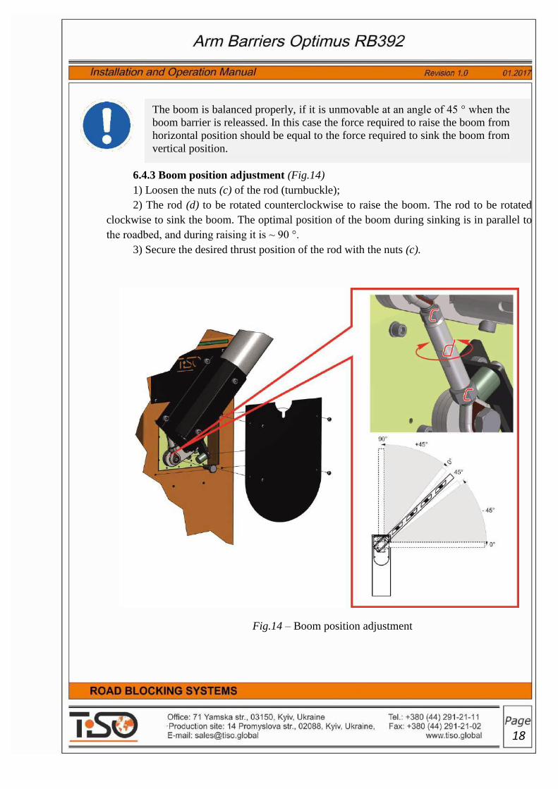
The boom is balanced properly, if it is unmovable at an angle of 45 ° when the
boom barrier is releassed. In this case the force required to raise the boom from
horizontal position should be equal to the force required to sink the boom from
vertical position.
6.4.3 Boom position adjustment (Fig.14)
1) Loosen the nuts (c) of the rod (turnbuckle);
2) The rod (d) to be rotated counterclockwise to raise the boom. The rod to be rotated
clockwise to sink the boom. The optimal position of the boom during sinking is in parallel to
the roadbed, and during raising it is ~ 90 °.
3) Secure the desired thrust position of the rod with the nuts (c).
Fig.14 – Boom position adjustment
19
The boom is considered to be adjusted properly when it is rather stable in
positions 0 ° and 90 °.
4) Adjust the position of
upper and lower props which
restrict the movement of arm
(barrier):
lower the barrier to the
position 'closed' with
the help of hilt for
manual control. (see
p.6.4.3):
- For changing of upper
prop position (fig. 15) -
it is necessary to loosen
nut and move stud in
the slot. Fix the required
position by tightening
the nut.
raise the barrier to the
position "open" with the
help of hilt for manual
control:
- The changing of the
lower prop is done
similarly to changing the
position of upper one.
With the correct setting
the barrier takes optimal
position relatively road
surface.
e) screw the mechanism
service panel with 4 screws..
Fig 16 - Adjusting the position of lower prop which
restrict the movement barrier
Fig 15 - Adjusting the position of upper prop which
restrict the movement barrier
upper prop
lower prop
20
Care should be taken when the boom barrier handle is used, since the boom
can move quickly due to relaxing or breakage of springs. In manual control
mode the boom to be moved at a moderate speed!
The boom barrier to be deenergized when raising/sinking is performed to
prevent the boom barrier movement caused by random command.
Manual control must not be used when the boom is not installed!
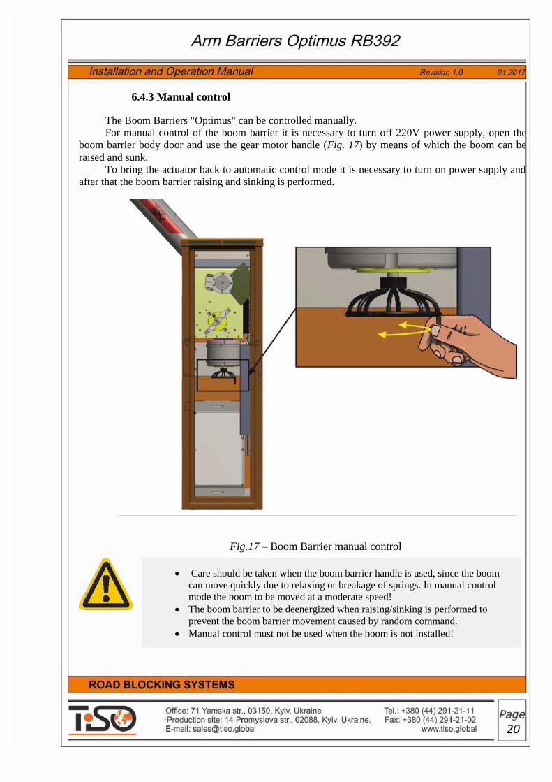
6.4.3 Manual control
The Boom Barriers "Optimus" can be controlled manually.
For manual control of the boom barrier it is necessary to turn off 220V power supply, open the
boom barrier body door and use the gear motor handle (Fig. 17) by means of which the boom can be
raised and sunk.
To bring the actuator back to automatic control mode it is necessary to turn on power supply and
after that the boom barrier raising and sinking is performed.
Fig.17 – Boom Barrier manual control

21
Make sure of the rack and boom installation accuracy and attachment security
prior to the boom barrier connection.
Power supply connection diagram and operation manual, Part II "Wiring and
operation of the road blockers of RB series", to be scrutinized.
The control unit is a standalone and independent device, which is wall mounted inside the
boom barrier rack.
The control unit is connected to the boom barrier with electric control cable and protective
earthing cable. The boom barrier electric cables to be put in plastic or corrugated pipe.
Electrical connection and operation of the boom barrier to be performed according to the
manual "OM. Part ІІ. Wiring and operation of the road blockers of RB series".
The boom barrier utilities to be connected when it is deenergized!
It is advised to put electrical cables in corrugated polyamide tube with
waterproof sealed connectors to protect them against mechanical damage
and environmental harmful impact.
The relevant instructions to be strictly followed during connection!
The boom barrier utilities to be connected only by the properly qualified
professionals!
7. BOOM BARRIER CONNECTION TO CONTROL UNIT

22
8.1 Preparation for precommissioning:
Compliance and reliability of the boom barrier and control unit electric cable terminal
connections to be checked;
The roadbed around the boom barrier to be restored;
The equipment power network to be checked;
Reliability of connection with earth loop to be checked.
8.2 Precommissioning:
Gear motor and control unit to be energized ;
Boom Barrier trial operation to be conducted;
The following shall be checked while conducting trial operation:
1. Gear motor performance parameters;
2. Control unit and remote control panel performance parameters;
3. Boom Barrier performance parameters.
The required equipment performance parameters to be adjuxted, if appropriate. If a fault is detected
it is necessary to trace the trouble and remedy it, if applicable*.(See Table 3).
The equipment precommissioning, adjustment, troubleshooting to be
performed only by the properly qualified professionals!
Safety regulations should be strictly observed during equipment
precommissioning and adjustment!
IT IS FORBIDDEN:
1. to prevent raising/sinking of the barrier boom;
2. to touch the boom barrier's moving parts during its operation;
3. to initiate movement of vehicles prior to complete sinking of the boom
barrier barrage elements.
The area adjacent to the boom barrier to be free and clear of foreign items.
8. PRECOMMISSIONING

23
If a fault can't be remedied based on this manual information, then the
relevant service department to be referred to.
Table 3. Boom Barrier Troubleshooting
Symptom Possible cause Remedy Notes
1 2 3 4
Barrier boom is raising
by fits and starts
1. Foreign objects in guiding
grooves.
2. Shafts are jammed.
3. Cylinder is jammed.
Guides to be cleaned and
shafts to be lubricated.
Incomplete raising and
sinking of boom
Foreign objects in guiding
grooves.
Guides to be checked and
cleaned from dirt and
foreign objects and
lubricated
Boom Barrier is out of
operation (control unit
LED display is absent)
Network voltage is absent or
fuse is blown
Network voltage to be
checked. Fuse to be
checked and replaced, if
appropriate (fuse
parameters to be complied
with label)
Boom Barrier is out of
operation (control unit
LED display is present)
Error in electrical
connections. Boom motion
interference. Boom Barrier
connections to be checked
Make sure that inputs of
devices with NC contact are
closed. Boom motion
interference to be removed
Boom Barrier is not
controlled by remote
control panel
(Remote control panel
LED display "is not lit
or
is lit dimly")
Remote control panel battery
is discharged
Remote control panel
battery to be checked and
replaced, if appropriate
Boom is not stopped in
end positions
End positions are not
adjusted or are wrong
Boom Barrier limit switch
positions to be adjusted
Boom is raising/sinking
by jerks or stops
Boom is not balanced Boom Barrier balancing
srings to be adjusted

24
9.1 To ensure the Boom Barrier continuous and reliable operation it is necessary:
to use the product according to its intended purpose;
all rules specified in this Manual shall be strictly observed during operation;
to provide maintenance and repair of equipment in due time;
to prevent the Boom Barrier operation and maintenance to be performed by unauthorized
persons;
9.2 Equipment Maintenance:
9.2.1 The boom barrier maintenance includes preventive measures to be taken according to the
established frequency to maintain the boom barrier in operational condition, decrease
component wearing and prevent faults and malfunctions.
9.2.2 Recommended types of the boom barrier maintenance (M):
Daily inspection (each shift);
M-1 (monthly);
M-2 (semiannually);
M-3 (annually);
Major repair (MR) – after 1500 000 cycles.
Table 4. Boom Barrier maintenance schedule
M type Frequency Scope of control/work
1 2 3
Daily
inspection
each shift
Normally the daily maintenance is performed before
commencement of work and includes visual inspection of
the boom barrier and, if required, prompt mechanical
troubleshooting, elimination of corrosion and surface
pollution.
The following control shall be conducted during daily
maintenance:
availability of all units and sensors in their proper
locations and their fastening security
The equipment examination and maintenance shall be performed according to
Schedule (See Table 4) and only by properly qualified professionals.
9. BOOM BARRIER OPERATION REGULATIONS

25
Table continuation 4
1 2 3
performance of all sensors and cable integrity;
boom barrier normal operation without jerks and
abnormal noises, jamming of movable constructional
elements;
motor heating (over 70°C).
M-1 monthly
M-1 is performed monthly and includes the following
measures:
measures in the scope of daily inspection;
elimination of dust from the boom barrier body and
components;
cleaning of actuators, sensors and drive;
verification of sensors fixation reliability and their
performance;
verification of good condition and fastening security
of cable connections to actuators and sensors;
check of availability and integrity of protective
fences and devices.
М-2 semiannually
M-2 maintenance is performed semiannually including the
following types of work:
measures in the scope of M-1; verification of fastening
security of units and devices.
М-3 annually
M-3 maintenance is performed annually including the
following types of work:
measures in the scope of M-2;
check of status of bearings, sealing cups and
lubrication;
blowing and cleaning of terminal boxes;
tensioning of screw joints of terminal boxes;
check of reliability and quality of cable connections
and earthing;
check of insulation resistance;
recovery of paint coatings.

26
Major repair is recommended to be performed by the manufacturer or dedicated repair service
according to the manufacturer’s documentation with the use of the manufacturer’s spare parts as
well as restored or manufactured by special repaire facilities according to the manufacturer's
documentation.
9.3. Safety regulations:
9.3.1 The appropriate safety measures shall be observed during operation and maintenance
of the boom barrier
9.3.2 The boom barrier must be repaired by the certified specialists having the relevant
electrical safety qualification permit to work with electrical facilities, safety briefed at workplace
and scrutinized the product instruction manuals.
9.3.3 It shall be the responsibility of the owner to ensure safety measures.
9.3.4 Hazardous characteristics during the boom barrier operation are:
- mechanical impact of raising/sinking dynamic part;
- electric shock by 220V.
9.3.5 Service and repair shall be performed only when the equipment is deenergized and a
forbidding safety sign according to ISO 7010: 2011 with notation “DO NOT SWITCH ON MEN
WORKING!” is put on initiator.
IT IS FORBIDDEN TO USE DEFECTIVE APPLIANCES, TOOLS,
INSTRUMENTATION THE SERVICE LIFE OF WHICH EXPIRED.
The time of maintenance and major repair can be increased or
decreased depending on actual parameters of the boom barrier
operation and fixed by the company operating this equipment.
All types of maintenance should be recorded in maintenance and
repair work sheet.

27
After completion of works safety signs should be removed and equipment should be actuated
only upon authorization of the work superintendent..
The barrier from the mains turn off with a switch (recommended bipolar circuit breaker or
RCD (Diff Auto) when installing the barrier in the open air), which on the barrier connection line
must be installed.
9.3.6 The Boom Barrier electrical equipment should be earthed. Resistance between
earthing bus and each accessible metal non-current-carrying part of the Boom Barrier electrical
equipment body should not exceed 4 Ohm..
9.3.7 General safety requirements accepted in the particular company should be in effect
during installation and operation of the Boom Barrier.
The safety requirements should be observed during preservation and depreservation.
9.3.8 The safety instructions specified in instruction manuals for purchased products and
control system should be additionally governed by.
9.3.9 The Boom Barrier operating in conjunction with other technological equipment should
have common locking with it.
IT IS FORBIDDEN:
to perform maintenance and repair works when the boom barrier
electrical equipment is energized;
to perform maintenance and repair works when the equipment is in
operation.
IT IS STRICTLY FORBIDDEN:
to allow the persons being unfamiliar with operation and safety rules to
service the boom barrier;
to use unearthed boom barrier;
to touch current carrying elements;
to touch movable parts of the boom barrier during operation;
to operate the boom barrier when protective devices and switches are
removed;
to prevent the boom barrier raising and sinking;
to use metalwork of the boom barrier for connection of neutral wire of
electric welder;
to perform welding works near the boom barrier without noncombustible
material protection to avoid its burning
Do not let children play with controls. Keep control panels out of reach of
children.

28
The warranty period is 1 year.
The warranty period is effective from the date of boom barrier sale.
The warranty is valid only subject to compliance with operation regulations and safety measures.
The warranty repair shall not be performed in the following cases:
- expiration of the warranty period;
- improper operation;
- the product bears the traces of tampering or attempt of unauthorized repair;
- damage resulted from the use of inappropriate accessories;
- damage caused by environment;
- damage resulted from the use of nonstandard or incompatible equipment;
- damage caused by exceeding of maximum permissible loads.
In all cases, when the product is not subject to warranty repair, a paid repair may be considered.
Warranty repair shall be performed upon availability:
Product datasheet;
Warranty coupon with stamped date of sale.
10. WARRANTY LIABILITIES
IMPORTANT!
Prior to operation of the boom barrier make sure that all units providing
safety of works are in good condition and properly installed;
It should be taken into account that the product could be damaged during
transportation;
Don’t disconnect the elements providing safety of works and don’t try to
modify them.
In case of any faults or defects, inform the person in charge of the product
service.

29
11. NOTES

30
Manufacturer:
"TiSO-PRODUCTION" LTD
72 Yamskaya str., 03150 Kiev, Ukraine
Tel.: +38 (044) 291-21-11
Tel../Fax:: +38 (044) 291-21-02
E-mail: [email protected],
WEB www.tiso.global
Our equipment complies with requirements of the European Standards::
EN ISO 12100: 2010, EN 60204-112006 / Att 2009l AC: 2010, EN 55011r2016,
EN 61000-4-2:2009
and is in conformity with requirements of the following EC Directives:
2014/35/EC; 2014/30/EU; 2006/42/ EC
QR-code to be used to download the Operation Manual via Internet.