Embed Size (px)
Citation preview

Organometallic Chemistry
Gary O. SpessardGary L. MiesslerSt. Olaf CollegeNorthfield, Minnesota
Oxford New York
OXFORD UNIVERSITY PRESS
2010
SECOND EDITION

Oxford University Press, Inc., publishes works that further Oxford University’sobjective of excellence in research, scholarship, and education.
Oxford New YorkAuckland Cape Town Dar es Salaam Hong Kong KarachiKuala Lumpur Madrid Melbourne Mexico City NairobiNew Delhi Shanghai Taipei Toronto
With offices inArgentina Austria Brazil Chile Czech Republic France GreeceGuatemala Hungary Italy Japan Poland Portugal SingaporeSouth Korea Switzerland Thailand Turkey Ukraine Vietnam
Copyright © 2010 by Oxford University Press, Inc.
Published by Oxford University Press, Inc.198 Madison Avenue, New York, New York 10016http://www.oup.com
Oxford is a registered trademark of Oxford University Press
All rights reserved. No part of this publication may be reproduced,stored in a retrieval system, or transmitted, in any form or by any means,electronic, mechanical, photocopying, recording, or otherwise,without the prior permission of Oxford University Press.
Library of Congress Cataloging-in-Publication DataSpessard, Gary O.
Organometallic chemistry / Gary Spessard, Gary Miessler.—2nd ed.p. cm.
Includes bibliographical references and index.ISBN 978-0-19-533099-1 (hardcover : alk. paper) 1. Organometallic chemistry. I. Miessler, Gary L., 1949– II. Title. QD411.S65 2010547′.05—dc22 2009019010
Printing number: 9 8 7 6 5 4 3 2 1
Printed in the United States of Americaon acid-free paper

xi
FIGURES
Chapter 1
Figure 1-1 Examples of Sandwich Compounds 2
Figure 1-2 Examples of Cluster Compounds 3
Figure 1-3 Anion of Zeise’s Compound 4
Figure 1-4 Conformations of Ferrocene 7
Figure 1-5 Vitamin B12 Coenzyme 10
Chapter 2
Figure 2-1 s, p, and d Orbitals 16
Figure 2-2 Interactions between Waves 19
Figure 2-3 Molecular Orbitals of H2 22
Figure 2-4 Molecular Orbitals of O2 23
Figure 2-5 Molecular Orbitals of CO 25
Figure 2-6 Molecular Orbitals of Linear H3+ 30
Figure 2-7 Molecular Orbitals of CO2 33
Figure 2-8 π Molecular Orbitals for π-C3H5 35
Figure 2-9 Construction of π Orbitals of Butadiene from Group Orbitals of Ethylene 37
Figure 2-10 Molecular Orbitals of Cyclic H3+ 38
Figure 2-11 Molecular Orbitals for Cyclic π Systems 41
Figure 2-12 π Molecular Orbitals of Benzene 42
Chapter 3
Figure 3-1 Molecular Orbitals of Cr(CO)6 (Only interactions between ligand (σ and π*) orbitals and metal d orbitals are shown.) 65
Figure 3-2 A t2g Orbital of Cr(CO)6 66
Figure 3-3 An eg* Orbital of Cr(CO)6 68
Figure 3-4 Exceptions to the 18-Electron Rule 69

xii Figures
Figure 3-5 Relative Energies of Metal d Orbitals for Complexes of Common Geometries 70
Figure 3-6 Examples of Square Planar d8 Molecules 70
Figure 3-7 Molecular Orbitals of Square Planar Complexes (Only σ donor and π acceptor interactions are shown.) 71
Chapter 4
Figure 4-1 Selected Molecular Orbitals of N2 and CO 76
Figure 4-2 σ and π Interactions between CO and a Metal Atom 76
Figure 4-3 Bridging versus Terminal Carbonyls in Fe2(CO)9 81
Figure 4-4 Bridging CO in [(η5–C5H5)Mo(CO)2]2 82
Figure 4-5 Binary Carbonyl Complexes 83
Figure 4-6 Oxygen-Bonded Carbonyls 87
Figure 4-7 Linear and Bent NO 89
Figure 4-8 Covalent and Ionic Approaches to Bonding in NO Complexes 90
Figure 4-9 Examples of NO Playing Multiple Roles 91
Figure 4-10 P4, [Ir(CO)3]4, P3[Co(CO)3], and Co4(CO)12 98
Chapter 5
Figure 5-1 Bonding in Ethylene Complexes 104
Figure 5-2 Examples of Allyl Complexes 105
Figure 5-3 Bonding in η3–Allyl Complexes 105
Figure 5-4 Examples of Molecules Containing Linear π Systems 106
Figure 5-5 Bonding in s-cis-Butadiene Complexes 107
Figure 5-6 Group Orbitals for the C5H5 Ligands of Ferrocene 110
Figure 5-7 Bonding Molecular Orbital Formed from dyz Orbital of Iron in Ferrocene 111
Figure 5-8 Antibonding Molecular Orbital Formed from dyz Orbital of Iron in Ferrocene 112
Figure 5-9 Molecular Orbital Energy Levels in Ferrocene 113
Figure 5-10 Molecular Orbitals of Ferrocene Having Greatest d Character 114
Figure 5-11 Reaction of Cobalticinium with Hydride 115
Figure 5-12 Electrophilic Substitution with Acylium Ion on Ferrocene 116
Figure 5-13 Structure of [Ti(η5–P5)2]2– 116
Figure 5-14 Complexes Containing C5H5 and CO 117
Figure 5-15 Examples of Chromium Complexes Containing Linked and Fused Six-Membered Rings 123
Figure 5-16 Half Sandwich Complexes Containing η6–C6H6 123
Figures xiii
Figure 5-17 Examples of Bonding Modes of Cyclooctatetraene 125
Figure 5-18 Bonding in Uranocene 126
Figure 5-19 Multiple–Decker Sandwich Compounds 127
Figure 5-20 Proposed Isomer of Ferrocene 127
Figure 5-21 Ring Whizzer Mechanism 132
Chapter 6
Figure 6-1 Structure of Re(CH3)6 139
Figure 6-2 π Bonding in Carbene Complexes and in Alkenes 142
Figure 6-3 Delocalized π Bonding in Carbene Complexes (E designates a highly electronegative heteroatom such as O, N, or S.) 143
Figure 6-4 Resonance Structures and cis and trans Isomers of Cr(CO)5[C(OCH3)C6H5] 144
Figure 6-5 Bonding in Carbyne Complexes 146
Figure 6-6 Complexes Containing Metal–Carbon Single, Double, and Triple Bonds 147
Figure 6-7 Carbide and Alkylidyne Complexes 148
Figure 6-8 Metallacumulene Complexes 151
Figure 6-9 Bonding in Dihydrogen Complexes 153
Figure 6-10 Examples of Agostic Interactions 155
Figure 6-11 Bonding between Phosphines and Transition Metals (traditional view) 155
Figure 6-12 Pi Acceptor Orbitals of Phosphines (revised view) 156
Figure 6-13 Ligand Cone Angle 158
Figure 6-14 C60 and C70 161
Figure 6-15 Fullerene Complex of Platinum 162
Figure 6-16 Bonding of C60 to Metal 163
Figure 6-17 [(Et3P)2Pt]6C60 164
Figure 6-18 (η2–C70)Ir(CO)Cl(PPh3)2 165
Figure 6-19 (µ3–η2:η2:η2–C60)Ru3(CO)9 165
Figure 6-20 Mass Spectrum of (η5:η5–C10H8)Mo2(CO)6 167
Figure 6-21 Isotope Patterns of Mo and Mo2 168
Figure 6-22 APCI Spectrum of [Cp(tfd)W(μ-S)2W(=O)Cp] (Upper: Actual spectrum; lower: calculated spectrum based on molecular formula and isotope distributions.) 169
Chapter 7
Figure 7-1 Spectral and Structural Characteristics of Pt(II) Complexes 180

xiv Figures
Figure 7-2 Activation Energy and the trans Effect (The depth of the energy curve for the intermediate and the relative heights of the two maxima will vary with the speciU c reactants.) 183
Figure 7-3 HOMO–LUMO Interactions of Hard and Soft Acids and Bases 187
Figure 7-4 Ligand Substitution of a Square Planar Complex 188
Figure 7-5 Intermediates in the Substitution of M(CO)5X Complexes 193
Figure 7-6 The Relationship of Transition State to Reaction Coordinate—The Hammond Postulate 195
Figure 7-7 Reaction Progress-Energy Diagram for the Addition of H2 to Vaska’s Compound 206
Figure 7-8 Interactions of Frontier Orbitals and H2 Molecular Orbitals 207
Figure 7-9 “Perpendicular” Approach of H2 to Metal Complex 207
Figure 7-10 Interactions of Frontier Metal and C−H Molecular Orbitals 211
Figure 7-11 Stereochemical Probes 224
Figure 7-12 Pd(II) Complexes Used for Reductive Elimination Studies 231
Chapter 8
Figure 8-1 Possible Mechanisms for CO Insertion Reactions 246
Figure 8-2 Mechanisms of Reverse Reactions for CO Migration and Alkyl Migration Related to Experiment II 248
Figure 8-3 Mechanisms of Reverse Reactions for CO Migration and Alkyl Migration Related to Experiment III 249
Figure 8-4 ClassiU cation of π Ligands 271
Figure 8-5 Relative Reactivity of π Ligands 271
Figure 8-6 π MOs of Allyl and 1,3-Butadiene 273
Figure 8-7 π-MOs of Unsymmetrical Allyl Ligands 277
Figure 8-8 Reactivity at Different Sites on Metal–Arene Complexes 281
Chapter 9
Figure 9-1 Reaction Progress versus Energy Diagrams for a Catalyzed and Uncatalyzed Reaction 313
Figure 9-2 A Schematic View of the Mechanism of Chymotrypsin-Catalyzed Amide Hydrolysis Occurring at the Enzyme Active Site 319
Figure 9-3 Stereoisomer of Metolachlor 379
Chapter 10
Figure 10-1 Molecular Orbital Diagram for Triplet and Singlet Free Carbene 396

Figures xv
Figure 10-2 InY uence of a Heteroatom Substituent on the Electronic State of a Free Carbene 397
Figure 10-3 (a) Interaction between a Singlet Free Carbene and a Metal;(b) Interaction between a Triplet Free Carbene and a Metal 401
Figure 10-4a Molecular Orbital Picture of a Fischer Carbene Complex 402
Figure 10-4b Molecular Orbital Picture of a Schrock Carbene Complex 403
Figure 10-5 π Donation in N-Heterocyclic Carbenes 405
Figure 10-6 Some Important N-Heterocyclic Carbenes 406
Figure 10-7 Reactive Sites of Transition Metal–Carbene Complexes 420
Figure 10-8 Frontier Orbital Interactions in Nucleophilic Attack on Fischer Carbene Complexes 421
Figure 10-9 The LUMOs of (a) Methyl Acetate and (b) Acetone 422
Figure 10-10 The HOMO of F3Nb=CH2 427
Figure 10-11a Molecular Orbital Bonding Scheme for a Fischer Carbyne Complex 442
Figure 10-11b Molecular Orbital Bonding Scheme for a Schrock Carbyne Complex 443
Figure 10-12a LUMO of a Cationic Fischer Carbyne Complex 447
Figure 10-12b LUMOs of a Neutral Fischer Carbyne Complex Showing Only the M−Ccarbyne Interactions 448
Chapter 11
Figure 11-1 Possible Dyad Tacticity and Double Bond ConU gurations Associated with ROMP of Norbornene 482
Figure 11-2 Cis-Syndiotactic and trans-Isotactic ConU guration during ROMP of Norbornene 482
Figure 11-3 Some Common Stereochemistries Resulting from Z–N Polymerization of Propene and Other 1-Alkenes 501
Figure 11-4 Modes of Approach and Insertion of Prochiral Propene onto a Metal Site and Growing Polymer Chain 503
Figure 11-5 Primary and Secondary Insertion of Propene in a Growing Polymer Chain 503
Figure 11-6 Molecular Orbital Correlation Diagram for σ Bond Metathesis 511
Chapter 12
Figure 12-1 Chiral Diphosphine Ligands 529
Figure 12-2 Free-Energy versus Reaction Progress Diagram for the Rate-Determining Step of Asymmetric Hydrogenation 531
Figure 12-3 Ru(II)-BINAP/Diamine Catalysts 540

xvi Figures
Figure 12-4 A Predictive Model for Enantioselection in Asymmetric Oxidation of Secondary Alcohols 551
Figure 12-5 The Relationship of Enantioselective Desymmetrization to Sense of Phosphine Orientation in C2-Symmetric Bisphosphine–Bisamide Ligands 562
Figure 12-6 Chiral Ligands That Promote Asymmetric Hydroformylation 573
Figure 12-7 Regioselectivity of Addition of an Aryl Halide to Various Alkenes during Heck OleU nation 578
Chapter 13
Figure 13-1 Octahedral and Tetrahedral Fragments 641
Figure 13-2 Orbitals of Parent Structures CH4 and ML6 641
Figure 13-3 Seven- and 17-Electron Fragments 642
Figure 13-4 Six- and 16-Electron Fragments 642
Figure 13-5 Molecules Resulting from the Combination of Isolobal Fragments 643
Figure 13-6 Isolobally Related Three-Membered Rings 644
Figure 13-7 Isolobally Related Tetrahedral Molecules 644
Figure 13-8 Isolobal Au(PPh3) and H 648
Figure 13-9 Coordinate System for Bonding in B6H62– 651
Figure 13-10 Bonding in B6H62– 652
Figure 13-11 Closo, Nido, and Arachno Borane Structures 654
Figure 13-12 Structures of Closo, Nido, and Arachno Boranes 654
Figure 13-13 Examples of Heteroboranes 657
Figure 13-14 Organometallic Derivatives of B5H9 659
Figure 13-15 Orbitals of Isolobal Fragments BH and Fe(CO)3 659
Figure 13-16 Comparison of C2B9H112– with C5H5
– (Each B and C atom also has a terminal H atom, not shown.) 660
Figure 13-17 Carborane Analogues of Ferrocene 661
Figure 13-18 Carbon- and Nitrogen-Centered Clusters 666
Figure 13-19 Bonding Interactions between Central Carbon and Octahedral Ru6 667

xvii
PREFACE
Organometallic chemistry is an exciting and rapidly-expanding field that has changed considerably over the 12 years intervening between the first edition of our textbook and the appearance of this new edition. Since 1997, six orga-nometallic chemists have been honored as Nobel Laureates because their work has had such an enormous impact, not only on the field but also to related areas of the chemical sciences, especially organic synthesis. The first edition indi-cated that π-bond metathesis would have significant bearing on the course of organometallic chemistry. We now realize that the applications of metathesis to organic synthesis constitute one of the most significant advances in the ability to construct complex molecules to occur in the past 50 years. The ready avail-ability of user-friendly software and high-speed computers has made computa-tional chemistry and molecular modeling important and routinely used tools for the elucidation of organometallic reaction mechanisms. High-level molecular orbital calculations have helped unravel the mysteries of catalytic cycles and allowed chemists to develop new chemistry based on the results and predictions of these computations. Recent developments in organometallic chemistry have been highly beneficial to practitioners of materials science, who produce exciting new substances, often through organotransition metal-catalyzed polymerization reactions.
DISTINCTIVE FEATURES OF THE SECOND EDITIONWritten with both undergraduate and graduate students in mind, Organometallic Chemistry introduces both audiences to their first in-depth study of the subject. The undergraduate audience will appreciate the logical progres-sion of topics in the early chapters that results in a careful and rigorous, but gentle introduction to concepts of structure and bonding of organometallic com-pounds. We anticipate that the graduate audience will find these early chapters a useful review of organic and inorganic chemistry concepts now applied specifi-cally to organotransition metal complexes. Later chapters build on this founda-tion and take both undergraduates and graduates to new levels of understanding

xviii Preface
by introducing rigorous coverage of organometallic reaction mechanisms and more advanced topics of catalysis, carbene complexes, metathesis, applications of organometallic chemistry to organic synthesis, and cluster compounds. Both audiences will benefit from the careful explanations, numerous exercises, clear illustrations, and coverage of key experiments.
Numerous in-chapter worked examples and expansive end-of-chapter problem sets reinforce fundamental concepts covered in the chapters. End-of-chapter problems cover a wide range of difficulty, from basic practice problems to more advanced analytical types of problems, and many of these are referenced directly to the current chemical literature.
An experimental approach is employed to teach students not only what is known about organometallic chemistry, but also how we know what we know. Therefore, the text includes discussions of both classic and contempo-rary experiments that have revealed the fundamental concepts underlying the subject.
Real-world applications are highlighted throughout the text to engage students and reveal the relevance of organometallic chemistry to everyday life, especially as it impacts the world of industry.
WHAT IS NEW IN THE SECOND EDITIONThe focus of our second edition remains organotransition metal chemistry, and the order of topics is substantially the same as that found in the first edition. As a thematic overview, readers will benefit from the following changes:
• Updated and expanded coverage of the latest developments from thefield, including IR, NMR, and mass spectroscopy; catalysis; carbenecomplexes; metathesis and polymerization; and applications to organicsynthesis.
• Increased presentation of industrial applications, including hydroform-ylation; Grubbs and Schrock metal carbene catalysts; SHOP; palladium-catalyzed cross-couplings; and more.
• New emphasis on green chemistry reveals how well the principlesof organotransition metal catalysis meld with the principles of greenchemistry.
• New computational approaches to molecular orbital calculations.• Increased number and variety of end-of-chapter problems and worked
examples. The new edition includes over 80% more end-of-chapter prob-lems and 50% more in-chapter worked examples than the previous edition.The problems cover a broad range of difficulty, and many of the end-of-chapter exercises are referenced directly to the original literature.

Preface xix
• More molecular model illustrations. The text now includes over 600illustrations and structures, a 25% increase over the previous edition. Atotal of 120 figures are brand new, and all preexisting figures have beenrevised for clarity and consistency.
Detailed Chapter-by-Chapter RevisionsChapter 2 retains its emphasis on a qualitative approach to molecular orbital theory; however, we have also added a section on computational chemistry. The thrust of this new section introduces readers to approaches to molecular orbital and molecular mechanics calculations employed by readily available commer-cial software packages. We make no attempt to thoroughly explain the theory behind these approaches, but instead we emphasize what each method can do and how it is applied to real chemical systems. Both qualitative and computational approaches to MO theory appear again throughout the text.
Chapter 3 introduces the 18-electron rule as a basis to help understand the bonding of several types of ligands to transition metals. These ligand types are covered in Chapters 4–6, where readers will discover how ligands combine with metals to form many unique and exquisitely beautiful structures that are quite distinct from those found in organic chemistry.
We have expanded coverage of spectroscopy in several ways. Chapter 4 introduces the use of infrared spectroscopy, especially its applications to car-bonyl complexes. C-13 and H-1 nuclear magnetic resonance spectroscopy are emphasized in Chapter 5 and P-31 NMR is introduced in Chapter 6. New to the second edition is the inclusion of a section on mass spectroscopy in Chapter 6. Chapters 4–6 contain numerous end-of-chapter problems, where spectroscopicinformation is an essential part of the exercise. Subsequent chapters have addi-tional spectroscopy problems.
Once readers understand the basic tenets of structure and bonding, they are ready to become acquainted with several kinds of reactions that involve organ-otransition metal complexes. Chapter 7 covers reactions that occur primarily at the metal. It has been expanded to include new material on C−H and C−C bond activation, an exciting area of organometallic chemistry with applications to the petrochemical industry and organic synthesis. Chapter 8 examines reac-tions that occur primarily on ligands attached to the metal, and the material in this chapter has been updated from the first edition. The reactions discussed in these two chapters appear again extensively in Chapters 9–12. We have tried wherever possible in Chapters 7 and 8 to point out obvious parallels of organometallic reactions to reactions in organic chemistry.
Catalysis plays an increasingly important role in all areas of chemistry. One of the major tenets of green chemistry is the use of catalysts instead of stoi-chiometric reagents wherever possible. Reactions catalyzed by organotransition

xx Preface
metals play key roles in industrial processes and in the laboratories of synthesis chemists. Chapter 9 has been expanded to include information on hydrocya-nation and the use of catalysis in the production of specialty chemicals. Since the publication of our first edition, green chemistry has become an increas-ingly important area. Originating in the industrial sector, green chemistry now plays an important role in the teaching laboratory, where significant efforts to make experiments more environmentally friendly are ongoing and bearing fruit. Chapter 9 (Catalysis) introduces some of the basic tenets of green chemistry, and green applications to organometallic chemistry are mentioned often, espe-cially in Chapter 12, where applications of organometallic chemistry to organic synthesis are covered.
Chapter 10 in the first edition covered metal carbene complexes, metathesis, and polymerization reactions. The chapter has now been split into two chapters. Chapter 10 now emphasizes the chemistry of carbene complexes; new mate-rial on N-heterocyclic carbene complexes, with applications in synthesis, has been introduced. Chapter 11 now considers metathesis and polymerization. The sections on the discovery and elucidation of π-bond metathesis have been rewritten and expanded. The discussion of both metathesis and Ziegler–Natta polymerization reactions has been considerably enhanced and brought up to date.
Application of organometallic chemistry to the synthesis of complex organic molecules continues to be one of the most interesting and exciting areas of organ-otransition metal chemistry. Chapter 12 updates material on asymmetric hydro-genation by considering Ir-catalyzed hydrogenation and new developments in Ru-catalyzed asymmetric hydrogenation. Asymmetric oxidation, which may have broader applications than hydrogenation, is now covered. Most of Chapter 12 emphasizes the use of organotransition metal compounds to catalyze the for-mation of new C−C bonds, often under asymmetric conditions. The chapter now includes enhanced sections on the Tsuji–Trost reaction, Heck olefination, and cross-coupling reactions. Whereas the first edition only considered Stille cross-coupling, Chapter 12 now includes material on the Suzuki, Sonogashira, and Negishi cross-coupling reactions, which have had enormous impact on synthesis in recent years.
Chapter 13 in the first edition covered a variety of topics relating to applica-tions of organometallic chemistry to other areas of science. This material has been eliminated with the exception of material on fullerenes, which now appears in Chapter 6. Chapter 13 updates the discussion of the isolobal analogy and cluster chemistry, which was the purview of Chapter 12 in the first edition.
Organometallic compounds are unique, useful, and esthetically pleasing. We hope readers of our book will also find this to be true and will learn much about a most important and interesting field of chemistry.

Preface xxi
SUPPLEMENTSThe following supplementary items are available to instructors who adopt the second edition:
Instructor’s Resource CD-ROM includes all figures from the text in electronic format and the solutions manual files containing the solutions to all exercises and problems from the textbook in editable Word file format. Please contact your publisher sales representative.
ACKNOWLEDGMENTS Production of the second edition was a huge project, and it could not have been possible without the help of many individuals. First and foremost, we thank our families (Carol, Sarah, Aaron, Becky, Naomi, and Rachel) for their forbearance and constant support during countless hours the authors spent at the computer and in the library over the past two years. We would also like to express appre-ciation to everyone at Oxford University Press, including Jason Noe, Chemistry Editor, and Melissa Rubes, Editorial Assistant, for all their hard work. In addi-tion, we thank Patrick Lynch, Editorial Director; John Challice, Vice President and Publisher; Adam Glazer, Director of Marketing; Preeti Parasharami, Product Manager; Steven Cestaro, Production Director; Lisa Grzan, Managing Editor; Paula Schlosser, Art Director; and Dan Niver and Binbin Li, Designers. We were aided at St. Olaf College by Karen Renneke, Chemistry Department Administrative Assistant, and student Stephanie Harstad, who provided valuable editorial contributions. Gary S. sincerely thanks the University of Arizona for allowing him full use of their library facilities.
We were privileged to have a distinguished group of educators review all or part of our manuscript for the second edition. These individuals provided extremely helpful feedback and numerous suggestions for improvement. The reviewers pointed out several errors in the manuscript that we had overlooked and have since corrected, and we are indeed grateful for their acumen. Most of the suggestions they made have been incorporated into this new edition; even if they were not, their comments forced us to refine our approach to the writing process. In addition to two reviewers who wish to remain anonymous, we specifi-cally acknowledge the following individuals for their substantial contributions to our efforts in creating the second edition:
Merritt B. Andrus, Brigham Young UniversityE. Kent Barefield, Georgia Institute of TechnologyLaurance G. Beauvais, San Diego State UniversityHolly D. Bendorf, Lycoming CollegeByron L. Bennett, Idaho State University (list continues on next p.)

xxii Preface
Steven M. Berry, University of Minnesota–DuluthPaul Brandt, North Central CollegeFerman Chavez, Oakland UniversityKenneth M. Doxsee, University of OregonEric J. Hawrelak, Bloomsburg University of PennsylvaniaAdam R. Johnson, Harvey Mudd CollegeKevin Klausmeyer, Baylor UniversityJay A. Labinger, California Institute of TechnologyMan Lung (Desmond) Kwan, John Carroll UniversityRobin Macaluso, University of Northern ColoradoJoel T. Mague, Tulane UniversityJames A. Miranda, Sacramento State UniversityKatrina Miranda, Arizona State UniversityLouis Messerle, The University of IowaChip Nataro, Lafayette CollegeJoseph O’Connor, University of California, San DiegoJodi O’Donnell, Reed CollegeStacy O’Reilly, Butler UniversityOleg Oszerv, Texas A&M UniversityDaniel Rabinovich, University of North Carolina–CharlotteSeth C. Rasmussen, North Dakota State UniversityKevin Shaughnessy, University of AlabamaRobert Stockland Jr., Bucknell UniversityJoshua Telser, Roosevelt UniversityKlaus H. Theopold, University of DelawareRory Waterman, University of VermontAnne M. Wilson, Butler UniversityDeanna L. Zubris, Villanova University
Furthermore, we are truly grateful to all our reviewers of the first edition and those individuals who provided much needed support:
Mitsuru Kubota, Harvey Mudd College Charles P. Casey, University of Wisconsin–Madison Philip Hampton, California State University Channel Islands Robert Angelici, Iowa State University Louis Hegedus, Colorado State University
Gary O. Spessard, Sierra Vista, ArizonaGary L. Miessler, Northfield, Minnesota

v
Figures xi
Preface xvii
Chapter 1 An Overview of Organometallic Chemistry 1
Chapter 2 Fundamentals of Structure and Bonding 13
Chapter 3 The 18-Electron Rule 53
Chapter 4 The Carbonyl Ligand 75
Chapter 5 Pi Ligands 103
Chapter 6 Other Important Ligands 136
Chapter 7 Organometallic Reactions I: Reactions That Occur at the Metal 176
Chapter 8 Organometallic Reactions II: Reactions Involving Modi� cation of Ligands 244
Chapter 9 Homogeneous Catalysis: The Use of Transition Metal Complexes in Catalytic Cycles 311
Chapter 10 Transition Metal–Carbene and –Carbyne Complexes: Structure,Preparation, and Chemistry 393
Chapter 11 Metathesis and Polymerization Reactions 456
Chapter 12 Applications of Organometallic Chemistry to Organic Synthesis 522
Chapter 13 Isolobal Groups and Cluster Compounds 640
Appendix A List of Abbreviations A-1
Appendix B Answers to Exercises A-5
Index I-1
BRIEF CONTENTS

vii
CONTENTS
Figures xi
Preface xvii
Chapter 1 An Overview of Organometallic Chemistry 11-1 Striking Difference 1
1-2 Historical Background 4
Chapter 2 Fundamentals of Structure and Bonding 132-1 Atomic Orbitals 13
2-2 Molecular Orbitals 21
2-3 Computational Organometallic Chemistry 42
Chapter 3 The 18-Electron Rule 533-1 Counting Electrons 53
3-2 Why 18 Electrons? 60
3-3 Square Planar Complexes 69
Chapter 4 The Carbonyl Ligand 754-1 Bonding 75
4-2 Binary Carbonyl Complexes 83
4-3 Oxygen-Bonded Carbonyls 86
4-4 Ligands Similar to CO 87
4-5 IR Spectra 92
4-6 Main Group Parallels with BinaryCarbonyl Complexes 96
Chapter 5 Pi Ligands 1035-1 Linear Pi Systems 103
5-2 Cyclic π Systems 107
5-3 Nuclear Magnetic Resonance Spectra ofOrganometallic Compounds 127
viii Contents
Chapter 6 Other Important Ligands 1366-1 Complexes Containing M–C, M=C, and M≡C Bonds 136
6-2 Hydride and Dihydrogen Complexes 152
6-3 Phosphines and Related Ligands 155
6-4 Fullerene Ligands 160
6-5 Mass Spectra 165
Chapter 7 Organometallic Reactions I: Reactions That Occur at the Metal 176
7-1 Ligand Substitution 178
7-2 Oxidative Addition 202
7-3 Reductive Elimination 226
Chapter 8 Organometallic Reactions II: Reactions Involving Modi� cation of Ligands 244
8-1 Insertion and Deinsertion 244
8-2 Nucleophilic Addition to the Ligand 267
8-3 Nucleophilic Abstraction 285
8-4 Electrophilic Reactions 289
Chapter 9 Homogeneous Catalysis: The Use of Transition Metal Complexes in Catalytic Cycles 311
9-1 Fundamental Concepts of Homogeneous Catalysis 312
9-2 The Hydroformylation Reaction 322
9-3 The Wacker–Smidt Synthesis of Acetaldehyde 340
9-4 Hydrogenation 350
9-5 Carbonylation of Methanol 361
9-6 Hydrocyanation 367
9-7 Specialty Chemicals 375
Chapter 10 Transition Metal–Carbene and –Carbyne Complexes: Structure, Preparation, and Chemistry 393
10-1 Structure of Metal Carbenes 394
10-2 Synthesis of Metal Carbene Complexes 407
10-3 Reactions of Metal–Carbene Complexes 419
10-4 Metal–Carbyne Complexes 439

Contents ix
Chapter 11 Metathesis and Polymerization Reactions 45611-1 π Bond Metathesis 456
11-2 Alkyne Metathesis 486
11-3 Ziegler–Natta and Related Polymerizations of Alkenes 492
11-4 σ Bond Metathesis 507
Chapter 12 Applications of Organometallic Chemistry to Organic Synthesis 522
12-1 Enantioselective Functional Group Interconversions 524
12-2 Carbon–Carbon Bond Formation via Nucleophilic Attack on an η3–π Ligand: The Tsuji–Trost Reaction 555
12-3 Carbon–Carbon Bond Formation via Carbonyl and Alkene Insertion 567
12-4 Carbon–Carbon Bond Formation via Transmetalation Reactions (Cross-Coupling Reactions) 584
12-5 Carbon–Carbon Bond Formation through Cyclization Reactions 613
Chapter 13 Isolobal Groups and Cluster Compounds 64013-1 The Isolobal Analogy 640
13-2 Cluster Compounds 650
Appendix A List of Abbreviations A-1
Appendix B Answers to Exercises A-5
Index I-1

ONE
1
An Overview of Organometallic Chemistry
Organometallic chemistry, the chemistry of compounds containing metal– carbon bonds, is one of the most interesting and certainly most rapidly growing areas of chemical research. It encompasses a wide variety of chemical compounds and their reactions: compounds containing both sigma (σ) and pi (π) bonds between metal atoms and carbon; many cluster compounds, containing two or more metal–metal bonds; molecules containing carbon fragments that are unusual or unknown in organic chemistry; and reactions that in some cases bear similarities to known organic reactions and in other cases are dramatically different. Aside from their intrinsically interesting nature, many organometallic compounds form useful cata-lysts and, consequently, are of significant industrial interest. Over the past several years, organometallic reagents have played the role of promoting key steps in the total synthesis of numerous molecules, many of which are biologically active.
1-1 STRIKING DIFFERENCESeveral examples illustrate how organometallic molecules are strikingly different from those encountered in classical inorganic and organic chemistry. Ligands1 of cyclic delocalized π systems (e.g., benzene or cyclopentadienyl) can team up with metal atoms to form “sandwich” compounds with a metal sandwiched between them. Sometimes atoms of other elements, such as phosphorus or sulfur, can be included as well. Examples of these double- and multiple-decker sandwich
1A ligand is a molecule, ion, or molecular fragment bound to a central atom, usually a metal atom.
ONE

2 Chapter 1 An Overview of Organometallic Chemistry
compounds are shown in Figure 1-1. The structure and bonding of sandwich com-pounds will be discussed in Chapter 5.
A characteristic of metal atoms bonded to organic ligands, especially CO (the most common of all ligands in organometallic chemistry), is that they often exhibit the capacity to form covalent bonds to other metal atoms to form dinuclear com-plexes and polynuclear cluster compounds (some known cluster compounds contain no organic ligands). These clusters may contain only three metal atoms or as many as several dozen; there is no limit to their size or variety. Dinuclear complexes may contain single, double, triple, or even quadruple bonds between the metal atoms and may in some cases have ligands that bridge two or more of the metals. Examples of metal cluster compounds containing organic ligands are shown as structures a, b, and c in Figure 1-2; cluster complexes will be encountered again in Chapter 13.
Carbon itself may play quite a different role than commonly encountered in organic chemistry. Certain metal clusters encapsulate carbon atoms; the resulting molecules, called carbide clusters, in some cases contain carbon bonded to five, six, or more surrounding metals.2 Figures 1-2d and e illustrate two examples of carbide clusters.
2The traditional notion of carbon forming bonds to at most four additional atoms must be reconsidered (a few examples of carbon bonded to more than four atoms are also known in organic chemistry).
Figure 1-1Examples of Sandwich Compounds
S
Fe
Cr
V
BB
Rh
Rh
MeMe
Me
Me
MeMe
Me
Me
Me
Me
Me
Me
B B
Fe
BS
B
MnCC
COO
O
MnCC C OO
O
Zn
MeMe
MeMe
Me
MeMe
MeMe
Me
Zn

1-1 Striking Difference 3
Figure 1-2Examples of Cluster Compounds
C
CC
C
Ir
C
P
CoCo
Ru Ru
Ru
Ru Ru
Pt
C
Co Co
P
C C OO
CCOO
CC
CCCC
C
O
O
OO
O
O
O
Fe(CO)3(OC)3Fe
(OC)3Fe Fe(CO)3
(CO)3Fe
a
b c
d
CO
PPh2
PPh2Ph2P
Ph2P
C CCO
OO
WMo
P
S
S
C
PhPh
O CC
W
PC
C
OO
OO
Ph
Ph
CWW
Ir
Me
COC
O
O
O
CO
CO
CO
O
Me
Me
e

4 Chapter 1 An Overview of Organometallic Chemistry
Strictly speaking, the only compounds classified as organometallic are those that contain metal–carbon bonds, but in practice complexes containing several other ligands similar to CO in their bonding, such as NO and N2, are frequently included. Other ligands, such as phosphines (PR3) and dihydrogen (H2), often occur in organometallic complexes, and their chemistry is closely associated with the chemistry of organic ligands. We will include examples of these and other non-organic ligands as appropriate in our discussion of organometallic chemistry.
1-2 HISTORICAL BACKGROUNDThe first organometallic compound to be reported was synthesized in 18273 by W.C. Zeise, who obtained yellow needle-like crystals after refluxing a mixture of PtCl4 and PtCl2 in ethanol, followed by the addition of KCl solution.4 Zeise cor-rectly asserted that this yellow product (subsequently dubbed “Zeise’s salt”) con-tained an ethylene group. This assertion was questioned by other chemists, most notably J. Liebig, and was not verified conclusively until experiments performed by K. Birnbaum in 1868. The structure of the compound proved extremely elu-sive, however, and was not determined until more than 140 years after Zeise’s discovery!5 Zeise’s salt proved to be the first compound containing an organic molecule attached to a metal using the π electrons of the former. It is an ionic compound of formula K[Pt(C2H4)Cl3] ⋅ H2O; the structure of the anion, shown in Figure 1-3, is based on a square plane, with three chloro ligands occupying cor-ners of the square and the ethylene occupying the fourth corner, but perpendicular to the plane defined by the Pt and Cl atoms.
3To place this in historical perspective, John Quincy Adams was the U.S. President at the time. The following year, Friedrich Wöhler reported that the organic compound urea could be made from the inorganic reagents HOCN and NH3—the “birth” of organic chemistry.4W. C. Zeise, Ann. Phys. Chem., 1831, 21, 497. A translation of excerpts from this paper can be found in Classics in Coordination Chemistry, Part 2, G. B. Kauffman, Ed., Dover: New York, 1976, pp. 21–37.5R. A. Love, T. F. Koetzle, G. J. B. Williams, L. C. Andrews, and R. Bau, Inorg. Chem., 1975, 14 , 2653.
Figure 1-3Anion of Zeise’s Compound
PtCl
Cl
Cl
C
C
HH
HH

1-2 Historical Background 5
The first compound containing carbon monoxide as a ligand was another plat-inum chloro complex, reported in 1867. In 1890, Mond 6 reported the preparation of Ni(CO)4, a compound that became commercially useful for the purification of nickel. Other metal CO (“carbonyl”) complexes were soon obtained; particularly notable was the work on iron carbonyls beginning around 80 years ago by Hieber.7
Reactions between magnesium and alkyl halides performed by Barbier 8 in 1898 and 1899, and subsequently by Grignard,9 led to the synthesis of alkyl mag-nesium complexes now known as Grignard reagents. These complexes contain magnesium–carbon σ bonds; they are multifaceted in their structure and function. In solution they participate in a variety of chemical equilibria, some of which are summarized in Scheme 1.1. Their synthetic utility was recognized early; by 1905, more than 200 research papers had appeared on the topic. Grignard reagents and other reagents containing metal–alkyl σ bonds (such as organolithium, organozinc,
6L. Mond, J. Chem. Soc., 1890, 57, 749.7W. Hieber and S. Fritz, Chem. Ber., 1928, 61B, 558.8P. Barbier, Compt. Rend., 1899, 128, 110.9V. Grignard, Comp. Rend., 1900, 130, 1322; Ann. Chim., 1901, 24, 433. An English transla-tion of most of the latter paper appeared in J. Chem. Ed., 1970, 47, 290.
Scheme 1.1Grignard Reagent Equilibria
X
Mg
X
Mg RR
2 RMgX
2 RMg+ + 2 X−
R2Mg + MgX2
RMg+ + RMgX2− X
Mg
X
Mg
R
R

6 Chapter 1 An Overview of Organometallic Chemistry
organocadmium, and organomercury reagents) have proven of immense impor-tance in the development of organic chemistry.
From the discovery of Zeise’s salt in 1827 to approximately 1950, the field of organometallic chemistry developed rather slowly. Some organometallic com-pounds, such as the Grignard reagents (RMgX), found utility in organic synthe-sis, but there was little study of compounds containing metal–carbon bonds as a distinct research area. In 1951, in an attempt to synthesize fulvalene (shown below) from cyclopentadienyl bromide, Kealy and Pauson allowed C5H5MgBr to react with FeCl3 using anhydrous diethyl ether as solvent (equation 1.1).10 This reaction did not yield the desired fulvalene, but rather an orange solid of formula (C5H5)2Fe that was later named ferrocene.
Fulvalene
MgBr + FeCl3 (C5H5)2Fe
Ferrocene 1.1
The product was surprisingly stable: it could be sublimed in air without decom-position and was resistant to catalytic hydrogenation and Diels–Alder reactions. In 1956, X-ray diffraction indicated the structure consisted of an iron atom “sand-wiched” between two parallel C5H5 rings.11 The details of the structure of ferro-cene proved somewhat controversial, with the initial study indicating the rings to be in a staggered conformation (Figure 1-4a). Electron diffraction studies of gas phase ferrocene, however, showed the rings to be eclipsed (Figure 1-4b), or very nearly so. More recent X-ray diffraction studies of solid ferrocene have identified several crystalline phases, with an eclipsed conformation at 98 K and confor-mations with slightly twisted rings (a skew conformation) in higher-temperature crystalline modifications (Figure 1-4c).12
10T. J. Kealy and P. L. Pauson, Nature 1951, 168, 1039. A report of the synthesis of “dicyclo-pentadienyliron” by Miller in 1952 showed a structure for C10H10Fe as two cyclopentadienyl groups attached to Fe by single bonds. Because Miller’s laboratory work occurred in 1948, he may have been the first to synthesize ferrocene without knowing its true structure. See S. A. Miller, J. A. Tebboth, and J. F. Tremaine, J. Chem. Soc., 1952, 632.11J. D. Dunitz, L. E. Orgel, and R. A. Rich, Acta Crystallogr., 1956, 9, 373.12E. A. V. Ebsworth, D. W. H. Rankin, and S. Cradock, Structural Methods in Inorganic Chemistry, 2nd ed., Blackwell Scientific Publications: Oxford, 1991, pp 414–417.

1-2 Historical Background 7
The discovery of the prototype sandwich compound ferrocene rapidly led to the synthesis of other sandwich compounds, other compounds containing metal atoms bonded to cyclic organic ligands, and a vast array of additional transition metal complexes containing other organic ligands. It is therefore often stated, with justification, that the discovery of ferrocene began the era of “modern” organometallic chemistry, an area that has grown with increasing rapidity in suc-ceeding decades.
Over the past 30 years, a major area of growth in organotransition metal chemistry has been the discovery and use of complexes containing chiral ligands. These compounds can catalyze the selective formation of specific enantiomers of chiral molecules. In some cases, the enantioselectivity of these reactions has even equaled that of enzymatic systems. A striking example is the catalytic reduction of β-ketoesters to β-hydroxyesters using ruthenium(II) complexes containing the chiral ligands (R)-BINAP and (S)-BINAP, as shown in Scheme 1.2.13 Selective synthesis of a single enantiomer in greater than 99% enantiomeric excess over the opposite enantiomer has been achieved. These results are comparable with the enantioselectivity achieved using enzymes from baker’s yeast!14 Chiral synthe-ses using organotransition metal complexes will be discussed in Chapters 9 and 12. Chapter 12 will also explore the incredible utility of organotransitionmetal reagents in promoting the formation of C−C bonds, the most important type of reaction in organic synthesis.
Already in this century, six chemists have received the Nobel Prize for seminal work in organometallic chemistry. Noyori, Knowles, and Sharpless became Nobel Laureates in 2001 as a result of their work on the use of organ-ometallic complexes to catalyze asymmetric hydrogenation and oxidation reactions of organic compounds. More details of this work will appear in Chapter 12. Just four years later, Chauvin, Grubbs, and Schrock were honored
13R. Noyori, T. Ohkuma, M. Kitamura, H. Takaya, N. Sayo, H. Kumobayashi, and S. Akutagawa, J. Am. Chem. Soc., 1987, 109, 5856.14Stereoselective reductions of β-ketoesters are of great importance in the biosynthesis of antibiotics and other biologically-active compounds.
Figure 1-4Conformations of Ferrocene
Fe Fe Fe
a b c

8 Chapter 1 An Overview of Organometallic Chemistry
with the Nobel Prize for their fundamental studies on the mechanism of π-bond metathesis, an example of which is shown in a catalytic ring-closing metath-esis reaction (equation 1.2).15 We will explore the impact of their research in Chapter 11.
15M. Scholl, S. Ding, C. W. Lee, and R. H. Grubbs, Org. Lett., 1999, 1, 953.
Et OMe
O O
Et OMe
O O
H2
RuBr2[(R)-BINAP]
H2
RuBr2[(S)-BINAP]
Et OMe
OH OH
Et OMe
H OHO
(R)-
(S)-
PPh2
PPh2
(R)-BINAP
PPh2
PPh2
(S)-BINAP
Scheme 1.2Enantioselective Synthesis Using Chiral Ru-BINAP Catalysts
+
(100% yield)
CRuCl
Cl
PCy3
Ph
H
NN
(5 mol %)
CH2Cl2/40 oC/10 min
EtO2C CO2Et
EtO2C CO2Et
1.2

1-2 Historical Background 9
Chapter 11 also explores polymerization reactions that are used to make giant molecules with many practical uses. Organotransition metal complexes play key roles in these transformations. Ziegler and Natta (who shared the 1963 Nobel Prize in Chemistry) were pioneers in the use of early transition metal compounds to catalyze the polymerization of ethene and propene. Stereoregular polymers resulted in the latter case, such as syndiotactic polypropene.
Me Me MeMe Me Me Me Me
Syndiotactic Polypropene
Finally, a discussion of the historical background of organometallic chem-istry would be incomplete without mention of what surely qualifies as the oldest known organometallic compound, vitamin B12 coenzyme (Figure 1-5). This naturally occurring cobalt complex contains a cobalt–carbon σ bond. It is a cofactor in a number of enzymes that catalyze 1,2-shifts in biochemical systems, such as the interconversion of methylmalonyl–CoA to succinyl–CoA (equation 1.3).
H2C CH
C
H
C
OO
SCoA
O
H2C CH C SCoA
O
COO
H
Methylmalonyl-CoA Succinyl-CoA 1.3
Chapter 1 has provided a mere glimpse of the huge number of compounds and numerous reaction types that encompass the area of science called organome-tallic chemistry. In the following chapters, we will focus on these compounds and the transformations they undergo, confining the treatment primarily to the struc-ture and chemical reactivity of molecules where a bond exists between carbon and a transition metal.16
16For a good discussion of main-group organometallic chemistry, see C. Elschenbroich, Organometallics, 3rd ed., Wiley-VCH: Weinheim, Germany, 2006, Chapters 4–11.

10 Chapter 1 An Overview of Organometallic Chemistry
NN
H2C
N
C
HN
OP
H
H
HOCH2
O HO
H H
O
O
MeO
−O
N
N
Me
H
CH2N
O
Me
C
H2N
OMe
Co
N
Me
H
Me
CNH2
C NH2
O
CO
NH2
O
H
C NH2
O
Me
Me
HH
OH HO
H H
O N
NN
N
NH2
Me
Me
Me
Figure 1-5Vitamin B12 Coenzyme
Suggested ReadingThe following articles by Dietmar Seyferth, listed in reverse chronological order, have appeared in the journal Organometallics over the past several years. Each gives a nice historical account of some key areas of organometallic chemistry.

Suggested Reading 11
1. “Alkyl and Aryl Derivatives of the Alkali Halides: Useful Synthetic Reagents as Strong Bases and Potent Nucleophiles. 1. Conversion of Organic Halides to Organoalkali–Metal Compounds,” 2006, 25, 2.
2. “Uranocene. The First Member of a New Class of Organometallic Derivatives of the f Elements,” 2004, 23, 3562.
3. “(Cyclobutadiene)iron Tricarbonyl—A Case of Theory before Experiment,” 2003, 22, 2.
4. “Bis(benzene)chromium. 2. Its Discovery by E. O. Fischer and W. Hafner and Subsequent Work by the Research Groups of E. O. Fischer, H. H. Zeiss, F. Hein, C. Elschenbroich, and Others,” 2002, 21, 2800.
5. “Bis(benzene)chromium. 1. Franz Hein at the University of Leipzig and Harold Zeiss and Minoru Tsutsui at Yale,” 2002, 21, 1520.
6. “Zinc Alkyls, Edward Frankland, and the Beginnings of Main-Group Organometallic Chemistry,” 2001, 20, 2940.
7. “[(C2H4)PtCl3]–, the Anion of Zeise’s Salt, K[(C2H4)PtCl3]·H2O,” 2001, 20, 2.
In addition, several articles appearing in the journal Pure and Applied Chemistry placed the development of organometallic chemistry in historical perspective.
1. Volume 78, issue 1 (2006), was dedicated to the theme of the application of organo-metallic chemistry to organic synthesis. Individual articles in this issue provide use-ful historical background.
2. A. Yamamoto, “Organometallic Chemistry. Past, Present, and Future,” 2001, 73, 205.
3. J. Halpern, “Organometallic Chemistry at the Threshold of a New Millenium. Retrospect and Prospect,” 2001, 73, 209.
Other ReadingsG. Wilkinson, “The Iron Sandwich. A Recollection of the First Four Months,”
J. Organomet. Chem., 1975, 100, 273. This article is a nice account of the history of the discovery of ferrocene. Wilkinson, along with E. O. Fischer, won the Nobel Prize in Chemistry for his pioneering work on sandwich compounds.
For a series of more modern articles by several authors on the history of the early research on ferrocene and other metallocenes, see J. Organomet. Chem., 2001, 637–639, 3–26. See also P. Laszlo and R. Hoffmann, “Ferrocene: Ironclad History or Rashomon Tale,” Angew. Chem. Int. Ed., 2000, 39, 123, for a short, interesting article on the discovery of the structure of ferrocene.
For an early article on the historical background of organometallic chemistry, see J. Thayer, Adv. Organomet. Chem., 1975, 13, 1.
For a historical perspective on the development of modern organometallic chemis-try from one of its most active participants, see F. A. Cotton, “A Half-Century of

12 Chapter 1 An Overview of Organometallic Chemistry
Nonclassical Organometallic Chemistry: A Personal Perspective,” Inorg. Chem., 2002, 41, 643.
The following article discusses the history of Natta’s discovery of stereoregu-lar polymers: P. Corradini, “The Discovery of Isotactic Polypropylene and Its Impact on Pure and Applied Science,” J. Polym. Sci., Part A, Polym. Chem., 2004, 42, 391.

TWO
13
Fundamentals of Structure and Bonding
An essential objective of organometallic chemistry is to understand how organic ligands can bond to metal atoms. An examination of the interactions between metal orbitals and orbitals on these ligands can provide valuable insight into how organometallic molecules form and react; such an examination may also indicate future avenues of study and potential uses for these compounds.
Before considering how ligands bond to metals, it is useful to look at the types of orbitals involved in such bonds. Chapter 2 includes a brief review of atomic orbitals, followed by a discussion of the ways in which atomic orbitals can interact to form molecular orbitals. Aspects of computational chemistry are introduced and discussed in terms of their relevance to organometallic chemistry. In subsequent chapters, we will consider how molecular orbitals of a variety of ligands can interact with transition metal orbitals. In these cases, we will pay particular attention to how metal d orbitals are involved.
2-1 ATOMIC ORBITALSThe modern view of atoms holds that although atoms are composed of three types of subatomic particles—protons, neutrons, and electrons—the chemical behavior of atoms is governed by the behavior of the electrons. Furthermore, the elec-trons do not behave according to the traditional concept of “particles,” but rather exhibit the characteristics of waves. In a single atom these waves can be described by the Schrödinger wave equation:
ψ = Eψ
TWO

14 Chapter 2 Fundamentals of Structure and Bonding
where
= Hamiltonian operatorE = energy of the electronψ = wave function
The wave function ψ can be represented by a mathematical expression describing the wave characteristics of an electron in an atom. The Hamiltonian operator, , is a set of mathematical instructions to be performed on ψ in such a way as to give a result that is a numerical value (the energy of the electron) multiplied by ψ. The details of the Hamiltonian operator need not concern us here; elaborate discus-sions can be found in a variety of physical chemistry texts. The characteristics of the wave function ψ, however, are essential background for understanding the discussion of chemical bonding that will follow.
The wave function ψ has the following important characteristics:
1. ψ is a mathematical description of a region of space (an orbital) that can be occupied by up to two electrons.
2. For any atom, there are many solutions to the wave equation. Each solution describes one of the orbitals of the atom.
3. ψ describes the probable location of electrons; it is not capable of predict-ing exactly where an electron is at a given place and time.
4. The square of the wave function, ψ2, evaluated at a given set of coordinates (x, y, z), is proportional to the probability that an electron will be at that point.
5. The mathematical expression of ψ incorporates quantum numbers, which are related to the energy, size, and shape of atomic orbitals.
Solutions to the Schrödinger equation are described by quantum numbers, as summarized in Table 2-1. Values for the first of these quantum numbers, n, l, and
Table 2-1 Quantum Numbers
Symbol Name Possible values Description
n Principal 1, 2, 3, . . . Describes size and energy of orbitals. (In older terminology, defined shell of electrons.)
l Azimuthal (angular momentum)
0, 1, 2, . . . , (n–1)l = 0 s orbitalsl = 1 p orbitalsl = 2 d orbitalsl = 3 f orbitals
Describes shape of orbitals; plays secondary role (after n) in determining energy. (In older terminology, defined subshell of electrons.)
ml Magnetic 0, ±1, ±2, . . . , ± l (integer values from -l to +l)
Describes orientation of orbitals. (The number of values of ml is the number of orbitals in a subshell.)
ms Spin 1–2 , – 1–2 Describes spin of electron in orbital.

2-1 Atomic Orbitals 15
ml, are obtained by solving the Schrödinger equation and define an atomic orbital; the fourth, ms, describes electron spin within an orbital.
The quantum number l gives the classification of an orbital (s, p, d, etc.) and determines the orbital’s shape. The number of values of the quantum number ml is equal to the number of orbitals having that classification, as shown below.
Classi� cation Number of orbitals
l = 0 ml = 0 (one value) s 1l = 1 ml = −1, 0, 1 (three values) p 3l = 2 ml = −2, −1, 0, 1, 2 (five values) d 5
The shapes and orientations of s, p, and d orbitals are extremely important in organometallic chemistry and are shown in Figure 2-1.
An atomic orbital is defined by its set of quantum numbers n, l, and ml. For example, a 2pz orbital has n = 2, l = 1, and ml = 0. Within an orbital, individual elec-trons may have quantum number ms = 1–
2 or – 1–2 . Because each electron in an atom
must have its own unique set of all four quantum numbers (according to the Pauli exclusion principle), if an orbital is filled, one electron must have ms = 1–
2 and the other must have ms = – 1–2. Quantum number ms is often designated by arrows:1
represents ms = 1–2
represents ms = – 1–2
1Solutions to all exercises are given in Appendix B.
a. Determine the possible values of quantum number l for a shell having n = 4.b. What values of quantum number ml are possible for a 3p orbital?c. How many electrons, at most, can occupy a 4p orbital?
Solutions:
a. Quantum number l can have integer values beginning with 0 and going up to n – 1. Therefore, l = 0, 1, 2, 3.
b. Values of ml are limited by the value of quantum number l. For any p orbital, l = 1. Therefore, ml = –1, 0, +1 (integer values between –l and +l).
c. No orbital, regardless of label, can be occupied by more than 2 electrons—so the answer is 2.
Example 2-1
a. How many electrons, at most, can occupy a shell having n = 2?b. What values of quantum number ml are possible for a d electron?c. At most, how many electrons in a p subshell can have ms = 1–2?
Exercise 2-11

16 Chapter 2 Fundamentals of Structure and Bonding
Figure 2-1 s, p, and d Orbitals
z
y x
s
px py pz
dxy dxz
dyz dx2-y2 dz2

2-1 Atomic Orbitals 17
Interactions between Atomic OrbitalsAtomic orbitals on neighboring atoms may interact with each other—if certain conditions are satisfied:
Atomic orbitals must have an appropriate orientation with respect to each • other and be close enough to interact.For such an interaction to be strong, the atomic orbitals should have similar • energies.
The molecular orbital (MO) concept of chemical bonding is based on these fundamental assumptions. As the name implies, MOs are similar in concept to atomic orbitals; in fact, molecular orbitals are derived from atomic orbitals. Both types of orbitals are based on the wave nature of electrons; therefore, all five characteristics listed previously for atomic orbitals also apply to molecular orbitals.
As stated, atomic orbitals on two atoms may interact if they are oriented appropriately with respect to each other.2 In general, if atomic orbitals point toward each other and interact directly between the nuclei, they participate in a σ interaction; if atomic orbitals are oriented such that they interact in two regions off to the side, they participate in a π interaction. Examples of these interactions follow.
σ interactions: π interactions:
2In other words, the orbitals must have the same symmetry to interact. Background on chemi-cal symmetry may be found in S. F. A. Kettle, Symmetry and Structure, Wiley: New York, 1995, and in G. L. Miessler and D. A. Tarr, Inorganic Chemistry, 3rd ed., Pearson Prentice Hall: Upper Saddle River, NJ, 2004, pp. 139–157.
s orbitals
p orbitals side by side
p orbitals side by sidep orbitals head to head

18 Chapter 2 Fundamentals of Structure and Bonding
In addition, whenever orbitals on two atoms interact, they do so in two ways: in a bonding fashion, in which the signs of the orbital waves match up, and in an antibonding fashion, in which the signs of the orbital waves are opposite. In a bonding interaction, electrons are concentrated between the nuclei and tend to hold the nuclei together; in an antibonding interaction, electrons avoid the region of space between the nuclei and therefore expose the nuclei to each other’s posi-tive charges, tending to cause the nuclei to repel each other. Thus, a bonding inter-action stabilizes a molecule, and an antibonding interaction destabilizes it.
2-1-1 σ InteractionsThe simplest case of a σ interaction is between s orbitals on neighboring atoms. Two types of interaction occur: bonding and antibonding. The bonding interac-tion leads to a molecular orbital (a bonding orbital, designated σ) that is lower in energy than the atomic orbitals from which it is formed; the antibonding interac-tion gives rise to a molecular orbital (an antibonding orbital, designated σ*; an asterisk is commonly used to indicate antibonding) that is higher in energy than the atomic orbitals from which it is formed. These interactions are shown below.
s s
σ
σ∗
Ene
rgy
+
+
Antibonding Interaction
Bonding Interaction
Similarly, p orbitals on adjacent atoms can interact. If the p orbitals are pointed directly toward each other, the interaction is classified as σ, and bonding and antibonding molecular orbitals are formed.
pz pz
σ
σ∗
Ene
rgy

2-1 Atomic Orbitals 19
These interactions may be compared conceptually with the way in which over-lapping waves interact (Figure 2-2). If (electron) waves on neighboring atoms overlap in such a way that their signs are the same, the result is constructive interference of the waves; the resulting wave, representing a bonding interaction, has a greater amplitude in the region between the nuclei. If the waves overlap such that their signs are opposite, the waves cancel each other out in the middle, creating a node of zero amplitude. This is an example of destructive interference and corresponds to an antibonding interaction.
2-1-2 π InteractionsSimilarly, parallel p orbitals on neighboring atoms can interact. In this case, the interaction occurs—not directly between the nuclei, as in the σ case—but in two regions off to the side. When the signs on the neighboring orbital lobes match, the interaction is a bonding one, leading to the formation of a π molecular orbital lower in energy than the p orbitals from which it is derived; when the signs on the neighboring lobes are opposite, an antibonding (π*) orbital is formed that is of higher energy than the original atomic orbitals. These are shown for p orbitals in two orientations on the next page.
Figure 2-2Interactions between Waves
+
+ Node
Destructive Interference
Constructive Interference

20 Chapter 2 Fundamentals of Structure and Bonding
2-1-3 NonbondingIf the orientations of atomic orbitals are such that a bonding interaction would be canceled by an equal antibonding interaction, there is no net interaction, and the orbitals are designated nonbonding. For example, a px orbital on one atom is not ori-ented suitably to interact with a pz orbital on a neighboring atom, as shown below.3
3In general, we will choose the z axis to be the axis joining the atomic nuclei.
Example 2-2 Classify the interactions between orbitals on two adjacent atoms as σ, π, or nonbonding (assign the z axis to pass through the atomic nuclei).
Atom 1 Atom 2 Diagram Classi� cation Example: s pz σ a. px px
b. px py
c. pz dz2
Solutions:
a. Two px orbitals: These orbitals interact in two regions; therefore, the classification is π.
b. A px orbital on the first atom, py on the second: Because there is no match of orbital lobes, these orbitals are nonbonding.
c. A pz orbital on the first atom, dz2 on the second: There is one region of overlap; the classification is σ.
Bonding
Antibonding
No interaction
px px
π
π∗
Ene
rgy
py py
π
π∗

2-2 Molecular Orbitals 21
Classify the interactions between orbitals on two adjacent atoms as σ, π, or nonbonding.
a. Atom 1: s; atom 2: py
b. Atom 1: dxz; atom 2: dxz
c. Atom 1: dz2; atom 2: dz2
Exercise 2-2
2-2 MOLECULAR ORBITALSWhen all possible orbital interactions between neighboring atoms are consid-ered, the result is a molecular orbital energy level diagram. In Chapter 2 we will consider first the simplest case: interactions between the orbitals of two atoms in diatomic molecules and ions. We will then extend this approach to consider the bonding in polyatomic organic π systems. Diatomic species and organic π sys-tems represent many of the most important ligands in organometallic chemistry.
2-2-1 Diatomic MoleculesDiatomic molecules are among the most important ligands occurring in organo-metallic compounds. We will therefore give special attention to the bonding in diatomics, considering first the homonuclear cases, such as H2 and O2, and then heteronuclear diatomics, such as CO.
In general, the atomic orbitals of the interacting atoms will be shown on the far left and far right of these diagrams and the molecular orbitals themselves in the middle. Relative energies of the orbitals will be indicated on the vertical scale of the diagrams.
Homonuclear DiatomicsMolecular Orbitals of H2. The simplest example of a diatomic molecule is H2. For this molecule, the only atomic orbitals available are the 1s orbitals of the hydrogens. These orbitals interact to yield bonding σ1s and antibonding σ1s
* molecular orbitals; the molecular orbital energy level diagram is shown in Figure 2-3. (Subscripts are often used to designate the atomic orbitals from which the molecular orbitals are derived.)
Electrons occupy the molecular orbitals beginning with the lowest energy orbital, in this case the σ1s. Consequently, H2 has one pair of electrons in a bond-ing molecular orbital; this is the same as saying that it has a single bond. Since H2 has only two electrons, it has no electrons left to occupy the higher energy antibonding orbital.
This picture of bonding can be compared with the Lewis dot structure, H : H, in which a single bond is designated by a pair of electrons shared between two atoms. In terms of molecular orbitals, a single bond is defined in H2 as a pair of electrons occupying a bonding molecular orbital.

22 Chapter 2 Fundamentals of Structure and Bonding
Bond OrderIn the molecular orbital model, the number of bonds between two atoms is designated as the bond order and depends not only on the number of bonding electrons, but also on the number of antibond-ing electrons. In general, the bond order can be determined from the following equation.4
Bond order = 1–2 (number of bonding electrons – number of antibonding electrons)
In the example of H2, the bond order = 1–2 (2 – 0) = 1 (a single bond). In diatomic
molecules, a bond order of 1 corresponds to a single bond, a bond order of 2 to a double bond, and so forth.
Suppose one wanted to consider whether He2 is likely to be a stable mol-ecule. This molecule, if it existed, would have a similar molecular orbital energy level diagram to H2 (in both cases, only 1s atomic orbitals are involved) but it would have four electrons: two in the bonding σ1s molecular orbital and two in the antibonding σ1s
* orbital. Its bond order would be = 1–2 (2 – 2) = 0, or no bond.
In other words, He2 would have no bond at all; not surprisingly, molecules of He2 have not been observed except under demanding experimental conditions.5
Magnetic BehaviorThe magnetic behavior of molecules is related to the presence or absence of unpaired electrons. Molecules such as H2 that have no unpaired electrons (both electrons are paired in the same orbital) are classified as diamagnetic; they are not attracted by magnetic
4In general, it is sufficient to consider only the valence electrons in the calculation of the bond order; inner electrons may be assumed to belong to individual atoms rather than participating significantly in bonding.5F. Luo, G. C. McBane, G. Kim, C. F. Giese, and W. R. Gentry, J. Chem. Phys., 1993, 98, 3564. See also L. L. Lohr and S. M. Blinder, J. Chem. Educ., 2007, 84, 860.
Figure 2-3 Molecular Orbitals of H2
1s 1s
σ1s
σ1s∗
En e
rgy
H H—H H

2-2 Molecular Orbitals 23
fields. Other molecules, as we will soon see, have unpaired elec-trons and are strongly attracted by magnetic fields. Such molecules are classified as paramagnetic.
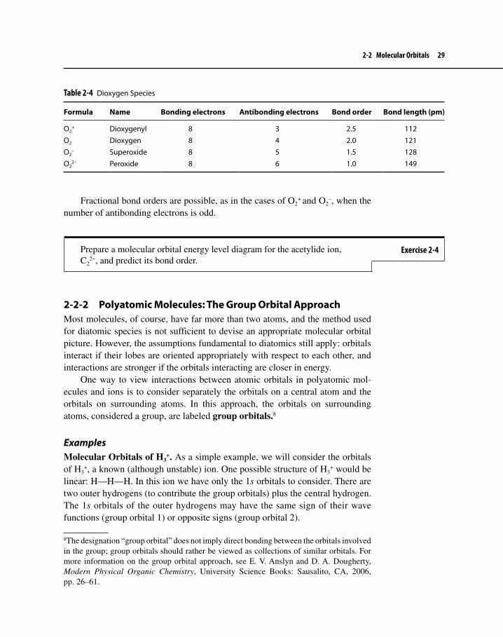
Second-Row Homonuclear Diatomic MoleculesSecond-row elements have 2s and 2p valence orbitals. Interactions between these orbitals give the molecular orbital energy level diagram shown in Figure 2-4. The molecule O2 is an example of this arrangement.
In O2, the 2s orbital interactions are similar to the 1s interactions in H2 and form σ2s and σ2s
* molecular orbitals. The 2p orbitals of the oxygens interact in both σ and π fashions.
One set of • σ interactions (involving 2pz orbitals) forms σ2p and σ2p* molec-
ular orbitals.Two sets of π interactions (one involving 2• px orbitals and the other involv-ing 2py orbitals) form two π2p orbitals and two π2p
* orbitals. Because the px
and py interactions are equivalent, the π2p orbitals have the same energy (are degenerate), and the π2p
* orbitals also have the same energy).
In general, σ interactions between 2p orbitals are stronger than π interactions; the σ interaction occurs directly between the atomic nuclei and has a somewhat stronger effect than the π interactions, which occur off to the side. Consequently,
Figure 2-4 Molecular Orbitals of O2
2s 2s
σ2s
σ2s∗
O O2 O
2p
σ2p
σ2p∗
2p
π2p∗
π2p

24 Chapter 2 Fundamentals of Structure and Bonding
the σ2p orbital is lower in energy than the π2p orbitals, and the σ2p* is higher in
energy than the π2p* orbitals, as shown.6
When the electrons are placed in the orbitals in order of increasing energy for O2, the first ten electrons fill the five lowest energy orbitals. The next highest orbitals in energy are the π2p
*. The final two electrons must occupy these orbitals in accordance with Hund’s rule, which states that electrons in such cases tend to occupy degenerate orbitals separately (to minimize electron–electron repul-sion by occupying separate regions in space) and with parallel spins (matching values of quantum number ms). The result is that the final two electrons in O2 occupy separate π2p
* orbitals and have parallel spins. Because these electrons are unpaired, O2 is paramagnetic; it behaves like a tiny magnet. Experiments have shown that O2 is, indeed, attracted by magnetic fields, lending support to the molecular orbital picture. The Lewis dot picture of O2, illustrated below, does not provide a way of predicting these unpaired electrons.
The bond order in O2 = 1–2 (8 − 4) = 2 (a double bond).
O O
The oxygen–oxygen distance of 120.7 pm in O2 is comparable to the distance expected for a double bond.
Heteronuclear DiatomicsMany diatomic molecules and ions contain two different elements; several play crucial roles in organometallic chemistry. Table 2-2 provides examples.
6The molecular orbital diagram illustrated in Figure 2-4 considers only interactions between atomic orbitals of identical energy: 2s with 2s and 2p with 2p. Interactions also occur between s and pz orbitals, however, as illustrated below. When these interactions are taken into account, the net effect is to raise the energy of the σ2p orbital relative to the π2p. In some cases, this interaction may be strong enough to push the σ2p higher than the π2p.
s pz
Table 2-2 Examples of Heteronuclear Diatomics of the Second-Row Elements
Formula Name Name as ligand
CO Carbon monoxide CarbonylCN− Cyanide CyanoNO+ Nitrosyl Nitrosyla
NO Nitric oxide Nitrosyl
aThe charge on the ligand when NO is bonded to a metal can be a matter of uncertainty. The name “nitrosyl” is used in general for NO ligands, without implications for the charge on the ligand or the oxidation state of the metal.

2-2 Molecular Orbitals 25
Molecular orbital energy level diagrams for these second-row heteronuclear diatomics can be drawn rather easily by modifying the homonuclear pattern slightly (as described for O2, Figure 2-4). The relative energies of the atomic orbitals should be shown, indicating that the more electronegative element has lower energy orbitals.
For example, in CO (Figure 2-5) the atomic orbitals of the more electronega-tive oxygen are lower, a reflection of the greater effective nuclear charge (oxygen has two more protons than carbon) pulling its orbitals to lower energy. The rela-tive energies of the molecular orbitals of CO are similar to those of O2.7
The shapes of the molecular orbitals should also be noted, especially because they have great chemical significance. In carbon monoxide, the bonding π orbit-als are skewed toward the more electronegative oxygen; the antibonding (and empty) π* orbitals are skewed toward the carbon. The large, empty lobes on carbon have immense importance in the numerous compounds containing CO bonded to metals (the order of atoms in these cases is almost always M−C−O), as
7The one exception: the σ2p orbital is higher in energy than the π2p orbitals in CO; the opposite is true in O2–see Footnote 6.
2s
2s
σ2s
σ2s∗
C CO O
2p
σ2p
σ2p∗
2pπ2p
∗
π2p
Figure 2-5 Molecular Orbitals of CO

26 Chapter 2 Fundamentals of Structure and Bonding
will be discussed in Chapter 4. In addition, the highest energy pair of electrons, in the σ2p orbital, is concentrated on the carbon; it also plays an important role in bonding to metals.
A useful reference is provided by the valence orbital potential energy; this is a measure of average potential energy of atomic orbitals. Valence orbital potential energies are negative, representing attractions between valence electrons and the nuclei; the more negative the value, the stronger the attraction and the lower the energy of the orbital. Valence orbital potential energies for the first 18 elements are given in Table 2-3.
In general, the more electronegative the element, the lower (more negative) the potential energies of the corresponding valence orbitals. For example, in CO the 2p orbitals of oxygen (−15.9 eV) are lower in potential energy than the 2p orbitals of carbon (−10.7 eV); this is shown in the molecular orbital diagram of CO (Figure 2-5) by indicating that the energies of the 2p atomic orbitals are lower in energy for oxygen than for carbon. The 2s orbital of oxygen is also much lower in energy than the 2s orbital of carbon.
Table 2-3 Valence Orbital Potential Energiesa
Orbital potential energy (eV)
Atomic number Element 1s 2s 2p 3s 3p
1 H −13.62 He −24.63 Li −5.44 Be −9.35 B −14.0 −8.36 C −19.4 −10.77 N −25.6 −13.28 O −32.4 −15.99 F −40.2 −18.710 Ne −48.5 −21.611 Na −5.112 Mg −7.613 Al −11.3 −6.014 Si −15.9 −7.815 P −18.8 −9.616 S −22.7 −11.617 Cl −25.2 −13.718 Ar −29.2 −15.8
aJ. B. Mann, T. L. Meek, and L. C. Allen, J. Am. Chem. Soc., 2000, 122, 2780.

2-2 Molecular Orbitals 27
Comparison of Atomic Orbitals with Molecular OrbitalsIn many ways molecular orbitals are like atomic orbitals.
1. Both types of orbitals have a definite energy and shape.2. Both types of orbitals can be occupied by up to two electrons; if two
electrons occupy the same orbital, they must have opposite spin (the Pauli exclusion principle applies).
3. In filling orbitals of the same energy (degenerate levels), electrons in both types of orbitals tend to occupy separate orbitals and have parallel spins (Hund’s rule applies).
4. Both types of orbitals describe probable locations of electrons, rather than exact locations (an orbital does not designate an orbit).
5. Both types of orbitals describe the wave nature of electrons; in some cases, a single orbital may have positive and negative portions (lobes) represent-ing positive and negative values of the corresponding wave functions (like peaks and valleys of waves on an ocean). For example, this is the case for π molecular orbitals and p atomic orbitals.
Molecular orbitals differ from atomic orbitals only in that the former arise from interactions between the latter, and molecular orbitals therefore describe the behavior of electrons in molecules rather than in single atoms.
A Suggested Procedure for Writing Molecular Orbital DiagramsThe molecular orbital concept is fundamental to organometallic chemistry. The exercises that follow provide useful practice in drawing MO energy level dia-grams. The following steps outline a recommended procedure:
1. Using valence orbital potential energies, indicate the relative energies of the atomic orbitals from which the molecular orbitals are derived. These are ordinarily shown on the far left and on the far right of the diagram (see Figures 2-3, 2-4, and 2-5). Generally, it is sufficient to use only the valence orbitals, especially in homonuclear diatomic molecules; the core electrons are located much closer to the nuclei than the valence electrons and, conse-quently, these inner electrons have only minor effects on the bonding (they are also filled with electrons and generate an equal number of bonding and antibonding electrons, giving no net effect on the bond order).
2. Show the bonding and antibonding molecular orbitals that result from interac-tions of the atomic orbitals. These are placed in the center of the diagram. (For convenience, the axis joining the nuclei is generally chosen as the z axis.)
3. Identify the molecular orbitals with appropriate labels:
σ for sigma interactions π for pi interactions

28 Chapter 2 Fundamentals of Structure and Bonding
4. Antibonding MOs are designated by an asterisk superscript. For example, an antibonding sigma orbital resulting from overlap of 2s atomic orbitals is designated σ2s
*.5. Place the appropriate number of electrons in the molecular orbital energy
levels by first determining the total number of valence electrons in the molecule or ion and then placing these in the molecular orbitals, starting with the lowest energy MO. Hund’s rule and the Pauli exclusion principle should be followed.
6. Check: Be sure that the total number of molecular orbitals is equal to the sum of the number of atomic orbitals used and that the total number of valence electrons in the molecular orbitals is correct.
Diatomic IonsHomonuclear diatomic ions can be treated in a manner similar to that used for neutral molecules. Although the relative energies of molecular orbitals in such ions may be somewhat different than in the neutral molecules, in general the molecular orbital diagram for the molecules may be used for the ions simply by adjusting the electron count. For example, the molecular orbitals of the ions O2
+, O2–, and O2
2– may be described using the orbitals for neutral O2 in Figure 2-4.
The results of this approach for O2 and its ions are shown in Table 2-4. As the number of electrons increases, the bond order decreases (the additional electrons occupy antibonding π* orbitals), and the oxygen–oxygen bond length increases.
Exercise 2-3 Prepare a molecular orbital energy level diagram of N2. Include labels for the molecular orbitals and all valence electrons. Predict the bond order for N2.
Example 2-3 Prepare a molecular orbital energy level diagram of the peroxide ion, O22−, and
predict the bond order of this ion.
Solution: The molecular orbital diagram is similar to that for O2, shown in Figure 2-4. The peroxide ion has two more antibonding electrons than neutral O2, giving a bond order of 1.
Bond order = 1–2 (8 – 6) = 1 (a single bond)
2-2 Molecular Orbitals 29
Fractional bond orders are possible, as in the cases of O2+ and O2
–, when the number of antibonding electrons is odd.
2-2-2 Polyatomic Molecules: The Group Orbital ApproachMost molecules, of course, have far more than two atoms, and the method used for diatomic species is not sufficient to devise an appropriate molecular orbital picture. However, the assumptions fundamental to diatomics still apply: orbitals interact if their lobes are oriented appropriately with respect to each other, and interactions are stronger if the orbitals interacting are closer in energy.
One way to view interactions between atomic orbitals in polyatomic mol-ecules and ions is to consider separately the orbitals on a central atom and the orbitals on surrounding atoms. In this approach, the orbitals on surrounding atoms, considered a group, are labeled group orbitals.8
ExamplesMolecular Orbitals of H3
+. As a simple example, we will consider the orbitals of H3
+, a known (although unstable) ion. One possible structure of H3+ would be
linear: H—H—H. In this ion we have only the 1s orbitals to consider. There are two outer hydrogens (to contribute the group orbitals) plus the central hydrogen. The 1s orbitals of the outer hydrogens may have the same sign of their wave functions (group orbital 1) or opposite signs (group orbital 2).
8The designation “group orbital” does not imply direct bonding between the orbitals involved in the group; group orbitals should rather be viewed as collections of similar orbitals. For more information on the group orbital approach, see E. V. Anslyn and D. A. Dougherty, Modern Physical Organic Chemistry, University Science Books: Sausalito, CA, 2006, pp. 26–61.
Table 2-4 Dioxygen Species
Formula Name Bonding electrons Antibonding electrons Bond order Bond length (pm)
O2+ Dioxygenyl 8 3 2.5 112
O2 Dioxygen 8 4 2.0 121O2
– Superoxide 8 5 1.5 128O2
2– Peroxide 8 6 1.0 149
Prepare a molecular orbital energy level diagram for the acetylide ion, C2
2−, and predict its bond order.Exercise 2-4

30 Chapter 2 Fundamentals of Structure and Bonding
In linear H3+, the only orbital available on the central hydrogen is its 1s. This
orbital is capable of interacting, in both a bonding and an antibonding fashion, with group orbital 1.
H H H H H H
Bonding interaction Antibonding interaction
The 1s orbital on the central hydrogen, however, cannot interact with group orbital 2; a bonding interaction on one side would be canceled by an antibonding interaction on the opposite side.
When sketching the molecular orbitals of polyatomic species, we begin by placing the valence orbitals of the central atom on the far left and the group orbitals of the surrounding atoms on the far right. We then show the resulting molecular orbital diagram in the middle. For H3
+ the molecular orbital energy level diagram is shown in Figure 2-6.9
In this ion, the single pair of electrons occupies the lowest-energy molecular orbital, a bonding orbital distributed over all three atoms. This implies a bond
9Note that the MO at the middle energy level in Figure 2-6 is group orbital 2. This MO is non-bonding. The nonbonding MO in this case is energy equivalent to a situation in which two 1s orbitals are positioned an infinite distance apart and incapable of interacting. Nonbonding energy levels typically result when an odd number of orbitals interact to form MOs.
Figure 2-6 Molecular Orbitals of Linear H3
+
Ene
rgy
H H H H H H
Central atom Group orbitals
H H H H H H
Group Orbital 1 Group Orbital 2

2-2 Molecular Orbitals 31
order of approximately one-half (half an electron pair per bond) and would be consistent with the observation that H3
+ is known, but not stable.10
Molecular Orbitals of CO2. In most cases of polyatomic molecules, p orbitals cause the orbital analysis to be much more complex than in the case of H3
+. Carbon dioxide is such a situation, involving valence p orbitals on both the central and the surrounding atoms. The group orbitals are on the oxygens and are of three types.
Type of group orbital Diagrams
s
O C O
px
py
pz (atomic orbitals pointedtoward each other)
px and py (atomic orbitalsparallel to each other)
To determine the types of interactions possible between the central carbon and the group orbitals, we must consider each of the types of group orbitals in turn.
1
2
2pz
1
σ
σ∗
Ene
rgy
• C • O C O O • O
2s
Group orbital 1 can interact with the 2pz orbital of carbon. (This interaction is likely to be weak, because the 2s orbitals of oxygen are much lower in energy than the 2p orbitals of carbon.)
2s
2
σ
σ∗
Ene
rgy
• C • O C O O • O
2s
Group orbital 2 can interact with the 2s orbital of carbon.
10H3+ is actually believed to be cyclic rather than linear, as will be discussed later in Chapter 2.
s Group Orbitals
O C O

32 Chapter 2 Fundamentals of Structure and Bonding
3
O C O
4
The interactions of the pz group orbit-als are similar to those in the case of the s group orbitals. Group orbital 3 can interact with the 2pz orbital of car-bon, and group orbital 4 can interact with the 2s orbital of carbon.
The px and py interactions differ only in their orientation. The px group orbit-als are as follows:
O C O
5
6
2px 6
π
π∗
Ene
rgy
2px
• C • O C O O • O
No orbital on the central carbon can interact with group orbital 5; this group orbital is nonbonding.
The 2px orbital of carbon, however, can interact with group orbital 6, as shown on the left.
The py interactions are similar to the px.
pz Group Orbitals
px and py Group Orbitals
2pz
3
σ
σ∗
Ene
rgy
2s
4
σ
σ∗
En e
rgy
• C • O C O O • O
• C • O C O O • O
2pz
2pz

2-2 Molecular Orbitals 33
The group orbitals are as follows:
7
O C O
8
2py8
π
π∗
Ene
rgy
2py
• C • O C O O • O
Because no atomic orbital on carbon is capable of interacting with group orbital 7, this group orbital is nonbonding.
Group orbital 8 can, however,interact with the 2py orbital of carbon in an interaction similar (except for orienta-tion) to that of group orbital 6.
The overall molecular orbital energy level diagram of CO2 is shown in Figure 2-7. The molecular orbital picture of other linear triatomic species, such
Figure 2-7Molecular Orbitals of CO2
For the linear ion FHF−, sketch the group orbitals on the fluorines and determine which of these orbitals can interact with the 1s orbital of hydrogen. Sketch a molecular orbital energy level diagram.
Exercise 2-5
1 2
3 4 5 6 7 8
2s
2p x y z
• C • O C O O • O

34 Chapter 2 Fundamentals of Structure and Bonding
as N3−, and CS2, can be determined similarly. A similar approach can also be
used in “linear” π systems, as described later in Chapter 2.
2-2-3 Ligands Having Extended π SystemsWhereas it is a relatively simple matter to describe pictorially how σ and π bonds occur between pairs of atoms, it is a somewhat more involved process to explain bonding between metals and organic ligands having extended π systems. How, for example, are the C5H5 rings attached to Fe in ferrocene (Figure 1-5) and how can such molecules as benzene and 1,3-butadiene bond to metals? To understand the bonding between metals and π systems, it is necessary to first consider the π bonding within the ligands themselves. Fortunately, the group orbital approach can be adapted to simplify these situations. In the following discussion, we first describe linear and then cyclic π systems; in later chapters we consider the question of how such systems can bond to metals.
ExamplesLinear π Systems. The simplest case of an organic molecule having a linear π system is ethylene, which has a single π bond resulting from the interactions of two 2p orbitals on its carbon atoms. Interactions of these p orbitals result in one bonding and one antibonding π orbital, as shown.
π*
π
p Orbitals Interacting Relative Energy
H2C CH2
The antibonding interaction has a nodal plane perpendicular to the internuclear axis, while the bonding interaction has no such nodal plane.
Next is the three-atom system, π–allyl, C3H5. In this case, there are three 2p orbitals to be considered, one from each of the carbon atoms participating in the π system. This situation can be viewed using the group orbital approach. The group orbitals here are derived from the parallel 2p orbitals on the terminal carbon atoms.
Group Orbital 1 Group Orbital 2

2-2 Molecular Orbitals 35
Group orbital 1 can interact, in both a bonding and an antibonding fashion, with the corresponding 2p orbital on the central carbon. Group orbital 2, on the other hand, is not suitable for interacting with any of the central carbon orbitals; this group orbital is nonbonding. The resulting molecular orbital energy level diagram for this three-atom π system is shown in Figure 2-8.
To extend this approach, we will find it useful to view these π interactions in a slightly different way. For the π–allyl system the possible interactions are as follows.
The lowest energy π molecular orbital for this system has all three p orbitals interacting constructively, to give a bonding molecular orbital. The nonbonding situation (πn), in which a nodal plane bisects the molecule, cutting through the
Figure 2-8 π Molecular Orbitals for π-C3H5
C C C C C C
Central atom Group orbitals
2p2p
π
π*
πn
C3H5
π
π*
πn
p Orbitals Interacting Relative Energy
CH2CH2C

36 Chapter 2 Fundamentals of Structure and Bonding
central carbon, is higher in energy. In this case, the p orbital on the central carbon does not participate in the molecular orbital (in general, nodal planes passing through the center of p orbitals and perpendicular to internuclear axes will “can-cel” these orbitals from participation in the π molecular orbitals). The antibonding π* orbital, in which there is an antibonding interaction between each neighboring pair of carbon p orbitals, is highest in energy. This can be compared with the π* orbital of ethylene, in which an antibonding interaction also occurs.
In these π systems, there is an increase in the number of nodes in going from lower energy to higher energy orbitals—for example, in the π–allyl sys-tem, the number of nodes increases from zero to one to two, from the lowest energy to the highest energy orbital.11 This is the same pattern of nodes as for linear H3
+ (Figure 2-6). This is a trend that will also occur in more extended π systems.
One additional example should suffice to illustrate this procedure. 1,3- Butadiene may exist in s-cis or s-trans forms (where s designates the central C−C σ bond). For our purposes, it will be sufficient to treat both as “linear” systems; the nodal behavior of the molecular orbitals will be the same in each case as in a linear π system of four atoms. As for ethylene and π–allyl, the 2p orbitals of the carbon atoms in the chain may interact in a variety of ways, with the lowest energy π molecular orbital having all constructive interactions between neighbor-ing p orbitals and the energy of the other π orbitals increasing with the number of nodes between the atoms.
p Orbitals Interacting Relative Energy
H2C CH CH CH2
11This does not include the nodal plane that is coplanar with the carbon chain, bisecting each p orbital participating in the π system.

2-2 Molecular Orbitals 37
This picture can also be derived by a group orbital approach, beginning with the π and π* orbitals of ethylene, as shown in Figure 2-9.12 The π orbitals of two interacting ethylenes form the two lowest energy π orbitals of butadiene and, similarly, the π* orbitals of the ethylenes can form the two highest energy π orbit-als of butadiene.
Similar patterns can be obtained for longer π systems.
Cyclic π Systems. The procedure for obtaining a pictorial representation of the orbitals of cyclic π systems of hydrocarbons is similar to the procedure for the linear systems described in the preceding section. Before discussing cyclic π sys-tems, however, let us consider again the simple case of H3
+, now examining a possible cyclic structure for this ion. One possible interaction for cyclo-H3
+ would have a bonding interaction between each participating 1s orbital.
12T. H. Lowry and K. S. Richardson, Mechanism and Theory in Organic Chemistry, Harper & Row: New York, 1987, p. 79.
Figure 2-9 Construction of π Orbitals of Butadiene from Group Orbitals of Ethylene
Ene
rgy
Sketch the π molecular orbitals for linear C5H7 and predict the relative energies of these orbitals.
Exercise 2-6

38 Chapter 2 Fundamentals of Structure and Bonding
Three atomic orbitals are involved; three molecular orbitals must also be formed. What are the other two? In the linear case, the middle molecular orbital had a single node and the highest energy molecular orbital had two nodes (Figure 2-6). Suppose the linear arrangement is wrapped into an equilateral triangle, with the nodes maintained.
The result is a pair of molecular orbitals in cyclic H3+, each with a single node.
Because they have the same number of nodes, they have the same energy (are degenerate), as illustrated in Figure 2-10. One pair of electrons occupies a bond-ing orbital, giving rise to the equivalent of a one-third bond between each pair of hydrogen atoms. This is believed to be the correct geometry of the highly reactive H3
+.
Cyclic HydrocarbonsThe smallest cyclic hydrocarbon having an extended π system is the cycloprope-nyl system, cyclo-C3H3. The lowest energy π molecular orbital for this system is the one resulting from constructive interaction between each of the 2p orbitals in the ring (top view).
Figure 2-10Molecular Orbitals of Cyclic H3
+
Ene
rgy

2-2 Molecular Orbitals 39
Two additional π molecular orbitals are needed (because the number of molecu-lar orbitals must equal the number of atomic orbitals used). Each of these has a single nodal plane that is perpendicular to the plane of the molecule and bisects the molecule; as in cyclo-H3
+, the nodes for these two molecular orbitals are per-pendicular to each other:
These molecular orbitals have the same energy; in general, π molecular orbit-als having the same number of nodes in cyclic π systems of hydrocarbons are degenerate. The total π molecular orbital diagram for cyclo-C3H3 can therefore be summarized as follows.
p Orbitals Interacting Relative Energy
cyclo-C3H3
A simple way to determine the p orbital interactions and the relative energies of the cyclic π systems having regular polygonal geometry is to inscribe the poly-gon inside a circle with one vertex pointed down; each vertex tangent to the circle then corresponds to the relative energy of a molecular orbital.13 Furthermore, the number of nodal planes bisecting the molecule (and perpendicular to the plane of the molecule) increases with higher energy, with the bottom orbital having zero nodes, the next pair of orbitals a single node, and so on. For example, the next cyclic π system, cyclo-C4H4 (cyclobutadiene), would be predicted by this scheme to have molecular orbitals as follows.14
13This operation is called the Frost–Hückel mnemonic or simply the circle trick.14This approach would predict a diradical for cyclobutadiene (one electron in each 1-node orbital). Although cyclobutadiene itself is very reactive (P. Reeves, T. Devon, and R. Pettit, J. Am. Chem. Soc.,1969, 91, 5890), complexes containing derivatives of cyclobutadiene are known. Cyclobutadiene itself is rectangular rather than square (D. W. Kohn and P. Chen, J. Am. Chem. Soc., 1993, 115, 2844) and at 8 K it has been isolated in a solid argon matrix (O. L. Chapman, C. L. McIntosh, and J. Pacansky, J. Am. Chem. Soc., 1973, 95, 614; A. Krantz, C. Y. Lin, and M. D. Newton, ibid., 1973, 95, 2746).
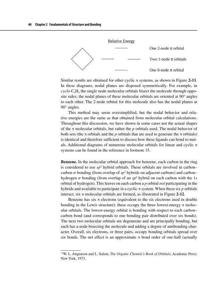
40 Chapter 2 Fundamentals of Structure and Bonding
Relative Energy
One 2-node π orbital
Two 1-node π orbitals
One 0-node π orbital
Similar results are obtained for other cyclic π systems, as shown in Figure 2-11. In these diagrams, nodal planes are disposed symmetrically. For example, in cyclo-C4H4 the single node molecular orbitals bisect the molecule through oppo-site sides; the nodal planes of these molecular orbitals are oriented at 90° angles to each other. The 2-node orbital for this molecule also has the nodal planes at 90° angles.
This method may seem oversimplified, but the nodal behavior and rela-tive energies are the same as that obtained from molecular orbital calculations. Throughout this discussion, we have shown in some cases not the actual shapes of the π molecular orbitals, but rather the p orbitals used. The nodal behavior of both sets (the π orbitals and the p orbitals that are used to generate the π orbitals) is identical and therefore sufficient to discuss how these ligands can bond to met-als. Additional diagrams of numerous molecular orbitals for linear and cyclic π systems can be found in the reference in footnote 15.15
Benzene. In the molecular orbital approach for benzene, each carbon in the ring is considered to use sp2 hybrid orbitals. These orbitals are involved in carbon–carbon σ bonding (from overlap of sp2 hybrids on adjacent carbons) and carbon–hydrogen σ bonding (from overlap of an sp2 hybrid on each carbon with the 1s orbital of hydrogen). This leaves on each carbon a p orbital not participating in the hybrids and available to participate in a cyclic π system. When these six p orbitals interact, six π molecular orbitals are formed, as illustrated in Figure 2-12.
Benzene has six π electrons (equivalent to the six electrons used in double bonding in the Lewis structure); these occupy the three lowest-energy π molec-ular orbitals. The lowest-energy orbital is bonding with respect to each carbon–carbon bond (and corresponds to one bonding pair distributed over six bonds). The next two molecular orbitals are degenerate and are principally bonding, but each has a node bisecting the molecule and adding a degree of antibonding char-acter. Overall, six electrons, or three pairs, occupy bonding orbitals spread over six bonds. The net effect is an approximate π bond order of one-half (actually
15W. L. Jorgenson and L. Salem, The Organic Chemist’s Book of Orbitals, Academic Press: New York, 1973.

2-2 Molecular Orbitals 41
Figure 2-11Molecular Orbitals for Cyclic π Systems
p Orbitals Interacting Relative Energy
cyclo-C3H3
cyclo-C4H4
cyclo-C5H5

42 Chapter 2 Fundamentals of Structure and Bonding
slightly less because of the nodes in the second and third orbitals), similar to the prediction of the Lewis model.
Many other cyclic molecules like benzene are known. Some of these are involved in another “classic” family of molecules: the sandwich compounds, in which atoms, most commonly of metals, are sandwiched between rings. These remarkable compounds have proven extraordinarily interesting since the proto-type, ferrocene, was synthesized in the 1950s. Examples of sandwich compounds are given in Chapter 1 (Figure 1-1); these are discussed further in Chapter 5.
2-3 COMPUTATIONAL ORGANOMETALLIC CHEMISTRYChemists have increasingly used computational chemistry to study aspects of organometallic chemistry. Although Chapter 2 and subsequent chapters make good use of qualitative molecular orbital theory, the ready availability of easy-to-use computational chemistry software and the powerful capability of modern desktop computers allow chemists to effectively model complex systems to obtain minimum energy geometry of molecules, determine transition state energies, and predict the course of chemical reactions, particularly if two or more isomeric products could form. Researchers have modeled entire catalytic cycles, which
Figure 2-12π Molecular Orbitals of Benzene
p Orbitals Interacting Relative Energy

2-3 Computational Organometallic Chemistry 43
is especially useful because intermediates in these cycles can be difficult to iso-late and characterize. Such studies have provided compelling evidence to support certain mechanistic hypotheses and have also allowed chemists to exclude other postulated mechanisms.
Computational chemistry can be divided into two major parts: (1) molecular mechanics (MM) and (2) MO theory. The MM approach is based on classical physics; MO theory is based on quantum mechanics. MM calculations are much less mathematically intensive than computations used for most MO methods; therefore, the former method is suitable for treating large molecules containing up to thousands of atoms. MM calculations are not suitable for locating transition states, however, because the parameters used in these calculations are derived from stable, isolable molecules. The MO approach is suitable for determining the energy and structure of a transition state because the method is designed to examine electron configurations of any molecular species.
2-3-1 Molecular MechanicsMM is based on the assumption that atoms in a molecule in the ground state adopt positions that will minimize the strain energy. Strain energy is caused by a number of factors, including: (1) bond deformation (the deviation of bond lengths in a molecule from “ideal” values; (2) angle deformation (the deviation of bond angles from “ideal” values; (3) torsional strain (dihedral angles that differ from “ideal” values give rise to torsional strain); (4) van der Waals strain (repulsion), which is also called steric hindrance; and (5) electrostatic repulsion (dipole– dipole interactions within a molecule are sometimes unfavorable). These factors comprise what is known as a force field.
Thus, the key part of a MM calculation is a systematic determination of the steric energy (Esteric) of a molecule, which is the sum of the five factors mentioned above as well as other components defined in the force field. The calculation uses equations derived from classical physics to either determine Esteric of the molecule, based on the input geometry, or compute this energy by systematically moving the atoms in the molecule and calculating the energy obtained after each movement. The latter process, called energy minimization, is an iterative procedure that uses mathematical criteria to determine when the minimum energy is reached.16 The higher the value of Esteric, the greater the deviation of the various factors, such as bond deformation, from ideal values. These ideal values are obtained from so-
16It must be pointed out that an energy minimum may be local, that is, it does not reflect the lowest energy geometry of the molecule, which is called the global minimum. Oftentimes MM calculations reach a local minimum according to preset criteria and then calculation ceases. Special efforts are then needed to prod the calculation to explore other geometries.

44 Chapter 2 Fundamentals of Structure and Bonding
called strain-free molecules and are entered into the computation as parameters. For example, an sp3-hybridized methyl carbon atom in an alkane has a different set of force field parameters than a methylidene carbon (=CH2). Thus, to perform a successful MM calculation, every atom in the molecule must have standard parameters of the force field assigned to it.
Different MM methods are available to chemists and abbreviations remi-niscent of the approach used to develop them are associated with each of them. Some of the methods suitable for use in organometallic chemistry are known as augmented MM2 and MM3, as well as UFF, which stand for molecular mechan-ics version 2 or 3 and universal force field, respectively. The force fields for each of these methods are parameterized for the transition metals as well as the ligands attached.
Esteric has no direct relationship to thermodynamic constants such as heat of formation (∆fHo). On the other hand, the difference in Esteric between two confor-mational isomers or two diastereomers is similar to ∆∆fHo for those isomers. This suggests that the application of MM to the prediction of which of two isomeric products is more likely to form is thermodynamically meaningful. MM serves as a quick method for determining minimum energy geometries of organometallic complexes as long as the user of such a method keeps in mind that sometimes the results are not in accord with experiment because improper parameters were used for the constituent atoms. MM has also been used to determine a quantity called the natural bite angle (βn) for bidentate ligands. The βn has been used to assess the efficacy of bidentate ligands involved in transition metal catalyzed reactions, which will be discussed in Chapter 9.
2-3-2 MO TheoryThe MO approach to molecular energy and other properties is fundamentally different than that of MM. In MM we assume that nuclei move and electrons are essentially “stationary,” that is, they are not explicitly considered in the force field calculations. Most MO approaches use the Born–Oppenheimer approximation, which considers nuclei relatively stationary compared with fast-moving elec-trons. Thus, the MO approach must somehow address electron motion and energy. Because the motion of electrons is governed by the Heisenberg Uncertainty Principle, quantum mechanical rather than classical physical calculations must be used.
An MO calculation is a many-body problem that cannot be solved exactly. Thus, various levels of approximation must be applied to determine MO energy levels and contours, molecular energy, and other characteristics of molecules. We will consider briefly these levels of approximation, which manifest themselves as MO methods that have acronyms associated with them, and also discuss how these methods can be applied to organometallic chemistry.

2-3 Computational Organometallic Chemistry 45
Ab initio MO TheoryAll MO calculations attempt to solve the Schrödinger equation (Ψ= EΨ) by setting up a Hamiltonian operator ( ) that contains terms for the potential and kinetic energy of the electrons in the molecule. The wave function Ψ is derived from a linear combination of basis set orbitals (typically atomic orbitals) from each atom in the molecule. The ab initio approach17 is the purest form of MO calculation, using the least degree of approximation, and it tries through itera-tive calculations to determine MO energy levels and other electronic molecular parameters by including the interactions of all atomic orbitals for the atoms in the molecule. The complexity of the calculation is a function of the complete-ness of the basis set of atomic orbitals. Most ab initio MO calculations divide pure atomic orbitals into a linear combination of wave functions such that even a simple molecule such as H2O can have a basis set as large as over 30 basis orbital wave functions.18 Clearly, the greater the complexity of the basis set of orbitals, the more intensive the calculation.19 Ab initio MO calculations using large, expanded basis sets are so computationally intensive that they are limited to molecules containing fewer than perhaps 50 atoms. On the other hand, high-level ab initio calculations can yield results for such characteris-tics as bond distance and dipole moment that are very close to experimental values.
Semi-empirical MO TheoryBefore the ready availability of high-speed computers, theoreticians realized that for them to perform MO calculations on anything but the very smallest mol-ecules, they would need to reduce the mathematical intensity of the computa-tion. They did this not only by making approximations that greatly reduced the size of the basis set (typically only the outer atomic orbitals are included in the calculation), but they also ignored the interaction of some of these basis set orbit-als, which often turned out to be small and thus could be neglected. To make the computation yield results that were close to experimental values, numerical parameters were added that were derived empirically by experiment, hence the term “semi-empirical.”
17Also known as Hartree–Fock (H–F) theory.18If only pure atomic orbitals were used for H2O, the basis set would consist of two 1s orbit-als for hydrogen and the 1s, 2s, and three 2p orbitals for oxygen, a total of seven orbitals.19Ab initio calculations scale by a factor of n4, where n is equal to the total number of basis orbitals. Contrast this with MM calculations, which scale by a factor of m2, where m is equal to the number of atoms in the molecule. The computational cost difference between these two methods is enormous for molecules containing 20 or more non- hydrogen atoms.

46 Chapter 2 Fundamentals of Structure and Bonding
Associated with semi-empirical MO theory are acronyms that indicate the various levels of approximation used. Some of these acronyms include CNDO, MINDO, MNDO, AM1, and PM3. These acronyms describe the level of mixing interactions of different atomic orbitals, not only on the same atom but also on adjacent atoms. The last three methods listed are most useful to organic chemists because, in addition to determining MO energy levels and providing chemists with pictorial representations of MOs, these procedures calculate ∆fHo directly. To do this, calculations are performed on “training sets” of organic molecules. Semi-empirical parameters are adjusted so that the calculation yields results that are equal to experimental heats of formation. If the semi-empirical calculations give reasonable heats of formation for every molecule in the training sets and if the training sets comprise a broad range of organic compounds, then semi-empirical calculations performed on almost any organic molecule, even those not included in the training sets, should yield accurate thermodynamic infor-mation. Work has continued to update training sets and modify semi-empirical parameters so that AM1 and PM3 calculations are generally quite reliable. Semi-empirical MO calculations can also be used as input for ab initio calcula-tions, thus saving computation time overall. Until quite recently, however, semi- empirical MO methods were not parameterized to include most of the transition metals. Thus, this approach has historically had limited value to organometallic chemistry.
Extended Hückel TheoryExtended Hückel Theory (EHT) uses the highest degree of approximation of any of the approaches we have already considered. The Hamiltonian operator is the least complex and the basis set of orbitals includes only pure outer atomic orbit-als for each atom in the molecule. Many of the interactions that would be con-sidered in semi-empirical MO theory are ignored in EHT. EHT calculations are the least computationally expensive of all, which means that the method is often used as a “quick and dirty” means of obtaining electronic information about a molecule. EHT is suitable for all elements in the periodic table, so it may be applied to organometallic chemistry. Although molecular orbital energy values and thermodynamic information about a molecule are not accessible from EHT calculations, the method does provide useful information about the shape and contour of molecular orbitals.
2-3-3 Electron CorrelationAll the MO methods that we have seen so far fail to consider explicitly the concept of electron correlation. Electron correlation addresses the tendency of electrons to repel one another and thus move about so that electron–electron repulsion is minimized. It accounts systematically for electrostatic interaction of electrons,

2-3 Computational Organometallic Chemistry 47
particularly those that are spin-paired in the same orbital. Thus, energies calcu-lated by ab initio MO methods give electronic energy levels that are too high. The difference between the calculated value and the true value is called the correlation energy. The ab initio approach does not address electron correlation directly, but instead treats one electron at a time in the presence of an average field composed of the remaining electrons in the molecule. Failure to account for electron cor-relation can lead to poor results, especially in the calculation of transition state energies.
Semi-empirical MO methods address electron correlation implicitly; they simply adjust parameters until the calculations give the “correct” answer com-pared with experiment. EHT does not address electron correlation at all, so quan-titative results from such calculations are almost always wrong unless fortuitous. There are, however, several approaches to explicitly account for electron cor-relation. One approach is to perform post-ab initio (post-H–F) calculations that in effect mix different electronic configurations involving the ground state and several excited states of the molecule. Such calculations are quite computation-ally intensive and can be performed only on relatively small molecules. Two commonly-seen acronyms associated with the post H–F approach to electron correlation are MP2 and CI, which stand for Møller–Plesset theory at the level of second-order and configuration interaction, respectively.
2-3-4 Density Functional TheoryDensity Functional Theory (DFT) is similar in some respects to high-level MO theory, but its approach is fundamentally different. DFT states that the total energy of a molecule and other useful properties can be derived from precise knowledge of the electron density (ρ) of a molecule. Instead of using wavefunctions that are comprised of basis atomic orbitals, DFT in principle can employ a function that describes the electron density at every point in a molecule. Although the concept is relatively simple, the derivation of appropriate functions that describe electron density and also thereby relate to total energy is not trivial. It turns out that ρ is a function of spatial coordinates (r). To relate ρ(r) to energy, DFT uses the mathematical concept of a functional, which is a function of a function. In other words, if f(r) = ρ (i.e., ρ is a function of r), then the functional that gives the energy is F[f(r)].
The exact form of F[f(r)] is impossible to determine exactly, but it can be approximated according to equation 2.1.
E = F[f(r)] = ET + EV + EJ + EXC 2.1
ET is a functional representing kinetic energy, EV gives the potential energy (nuclear–electron attraction and nuclear–nuclear repulsion), and EJ is a cou-lombic functional that represents electron–electron repulsion. The sum of the

48 Chapter 2 Fundamentals of Structure and Bonding
first three terms of equation 2.1 represents the classical energy of the charge distribution of the molecular system. The exchange-correlation term is given by EXC, which is not so straightforward to describe. Usually DFT calculations divide EXC into two parts, one representing exchange interactions of electrons based on the Pauli Exclusion Principle and the other representing electron cor-relation effects. The exchange functional is not based on classical notions, such as kinetic and potential energy, but instead derives from the quantum mechani-cal treatment of electron behavior. Because DFT explicitly includes an electron correlation term, the answers it provides automatically reflect the effects of electron correlation.
Now that we have a theoretically sound basis for determining molecular energy and other parameters on the basis of electron density, the task remains to put this theory into practice. Unfortunately, the functional EXC cannot be explicitly described and its value is not known. Theoreticians Kohn and Sham derived a set of equations that allows the evaluation of EXC.20 The exact proce-dure they developed goes beyond the scope of this text, but it can be described qualitatively. The Kohn–Sham equations use a basis set of orbitals, very simi-lar to those employed for ab initio MO theory, to determine a suitable repre-sentation of EXC. The process involves using a functional that incorporates the basis orbitals and first guessing at a trial solution. Then the result obtained using the trial solution is used to determine a new solution, and the process continues iteratively until self-consistency is reached. To augment the Kohn–Sham approach and make it more practical for actual computer calculations, approximations to EXC have been developed by several theoreticians using empirical data. Thus, DFT contains elements of a semi-empirical approach in these cases. Two acronyms attached to DFT calculations are B3LYP and PW91, where the letters refer to the individuals who developed the method. Often the DFT method chemists apply is abbreviated to indicate the method employed to determine EXC and the basis set of Kohn–Sham orbitals used, for example, B3LYP/6–31G.
A major advantage of DFT theory is its relatively low computational inten-sity compared with post-ab initio electron correlation calculations.21 Because DFT calculations can be augmented with empirical data relevant to the transition metals, they are now the preferred approach to theoretical studies of organotransi-tion metal chemistry. We must point out, however, that theoreticians still cannot know ahead of time which DFT method will work best for a particular situation;
20W. Kohn and I. J. Sham, Phys. Rev. A, 1965, 140, 1133.21The computational cost of most DFT calculations is approximately the same as that for ab initio methods using large basis sets of orbital functions.

Suggested Reading 49
often, more than one brand of calculation must be used for comparison purposes. Efforts to improve DFT by introducing variations that will behave in a predictable fashion are ongoing.
Table 2-5 compares the characteristics and utility of all of the methods we have just considered.
Suggested Reading
Atomic and Molecular OrbitalsH. B. Gray, Chemical Bonds: An Introduction to Atomic and Molecular Structure,
Benjamin: Menlo Park, CA, 1973.Y. Jean, F. Volatron, and J. Burdett, An Introduction to Molecular Orbitals, Oxford
University Press: New York, 1993.
Table 2-5 Comparison of Computational Chemistry Methods
Method Accuracy Utility
Suitability for organometallic chemistry
Computational cost
Molecular scale
Molecular Mechanics (MM)
Fair to good; depends on atom parameterization
Energy comparison of conformers and diastereomers
Good if augmented parameters for transition metals are used
Low Up to thousands of atoms
Ab initio MO Theory
Good if large basis sets of orbitals are used and post-H-F calculations are performed
Equilibrium and transition state geometries; reaction energy calculations
Poor Medium to high; depends on basis set; if post-H-F calculations are done, cost is very high
Up to 50 atoms
Semi-empirical MO Theorya
Now good for most organometallic molecules
Same as ab initio MO theory; ∆fHo values
Good; most transition metals are now parameterized
Medium Up to thousands of atoms
Extended Hückel Theory (EHT)
Poor Determining shapes of MOs
Good Low Up to 100 atoms or more
Density Functional Theory (DFT)
Generally good; depends on method
Same as ab initio MO theory
Good High Up to 50 atoms
aA new edition of semi-empirical MO software (PM6 from MOPAC2009TM) is available that is much more powerful than older editions, which were not suitable for calculations on organotransition metal complexes.

50 Chapter 2 Fundamentals of Structure and Bonding
J. G. Verkade, A Pictorial Approach to Molecular Bonding and Vibrations, 2nd ed., Springer–Verlag: New York, 1997.
J. K. Burdett, Chemical Bonds: A Dialog, Wiley: Chichester, England, 1997.
Computational ChemistryE. G. Lewars, Computational Chemistry: Introduction to the Theory and Applications of
Molecular and Quantum Mechanics, Kluwer Academic: Boston, 2003.C. J. Cramer, Essentials of Computational Chemistry: Theory and Models, Wiley:
Chichester, England, 2002.A. Leach, Molecular Modeling: Principles and Applications, 2nd ed., Prentice Hall:
Upper Saddle River, NJ, 2001.Computational Organometallic Chemistry, T. R. Cundari, Ed., Dekker: New York, 2001.W. Koch and M. C. Holthausen, A Chemist’s Guide to Density Functional Theory,
Wiley–VCH: Weinheim, Germany, 2000.F. Jensen, Introduction to Computational Chemistry, Wiley: Chichester, England,
1999.A. K. Rappe and C. J. Casewit, Molecular Mechanics across Chemistry, University
Science Books: Sausalito, CA, 1997.W. J. Hehre, L. Radom, P. v. R. Schleyer, and J. Pople, Ab Initio MO Theory, Wiley:
New York, 1986.
Problems2-1 What are possible values of the following?
a. Quantum number l for a shell having n = 3b. Quantum number ms for two electrons occupying the same orbitalc. Quantum number ml for p electronsd. Quantum number ml for electrons in a 4d subshell
2-2 Classify the interactions between orbitals on two adjacent atoms as σ, π, or nonbonding. Assume that the two atoms aligned along the horizontal axis (z-axis), and the y-axis is the vertical axis.
a. Atom 1: dyz; atom 2: dyz
b. Atom 1: py; atom 2: dxz
c. Atom 1: dz2; atom 2: s
2-3 Classify the interactions between orbitals on two adjacent atoms as σ, π, or nonbonding. Assume that the two atoms aligned along the horizontal axis (z-axis), and the y-axis is the vertical axis.
a. Atom 1: s; atom 2: py
b. Atom 1: pz; atom 2: dxy
c. Atom 1: py; atom 2: py

Problems 51
2-4 Prepare a molecular orbital energy level diagram for nitric oxide (NO) and predict the bond order of this molecule. On the basis of the molecu-lar orbital diagram, what do you predict for the bond orders of NO+ and NO–? Which of these diatomic species would you expect to have the shortest bond length? Why?
2-5 The shapes of the π and π* orbitals of diatomic ligands are important in organometallic chemistry.
a. Sketch the expected shapes of the π and π* orbitals of the following:
N2 CN– CO BO–
b. What trends do you predict in the shapes of these orbitals? Why do you expect such trends? (Hint: Consider relative electronegativity.)
2-6 Now use molecular modeling software to generate the shapes of the π and π* orbitals of the molecules and ions listed in the preceding prob-lem. What trends do you observe? Are these consistent with trends in electronegativities?
2-7 On the basis of molecular orbitals, predict the shortest bond in each set.
a. H2+ H2
b. NO+ NO NO–
c. CO+ CO
2-8 Is H4 a plausible molecule? Using the approach described in Chapter 2, sketch the molecular orbitals (show interacting orbitals, nodes of molec-ular orbitals, and relative energies of molecular orbitals) for the follow-ing geometries:
a. Linearb. Square
Which, if either, would you expect to be a more likely structure?2-9 For the linear azide ion, N3
−, sketch the group orbitals and deter-mine which of these orbitals can interact with the valence orbitals of the central nitrogen. Classify the possible interactions as σ, π, or nonbonding.
2-10 Sketch the π orbitals of 1,3,5-hexatriene, C6H8, and predict the relative energies of the orbitals. Indicate clearly the locations of the nodes.
2-11 Sketch the π orbitals of cyclo-C7H7 and predict the relative energies of these orbitals. Indicate clearly the locations of the nodes.
2-12 Now use molecular modeling software to calculate and display the π molecular orbitals of the following molecules:
a. π–Allyl, C3H5. Compare your results with Figure 2-8.

52 Chapter 2 Fundamentals of Structure and Bonding
b. 1,3,5-Hexatriene, C6H8. Compare your results with your sketches in problem 2-10.
c. Cyclobutadiene, C4H4. Compare your results with the diagrams shown for this molecule in Figure 2-11.
d. cyclo-C7H7. Compare your results with your sketches in problem 2-11.

TWO
53
In main group chemistry, electron counts in molecules are often described by the octet rule, in which electronic structures can be rationalized on the basis of a valence shell requirement of 8 electrons (two valence s electrons plus six valence p electrons). Similarly, in organometallic chemistry the electronic structures of many compounds are based on a total valence electron count of 18 on the cen-tral metal atom (ten valence d electrons in addition to the s and p electrons of the “octet”). As in the case of the octet rule, there are many exceptions to the 18-electron rule,1 but the rule nevertheless provides some useful guidelines tothe chemistry of many organometallic complexes. In Chapter 3 we first examinehow electrons are counted according to this rule. We then consider the basis forits usefulness (and some of the reasons why it is not always valid).
3-1 COUNTING ELECTRONSSeveral schemes exist for counting electrons in organometallic compounds. We will describe two of these using several examples. The first two examples are of classic 18-electron species.
3-1-1 Method A: Donor Pair MethodThis method considers ligands to donate electron pairs to the metal. To deter-mine the total electron count, one must take into account the charge on each
1Also called the effective atomic number (EAN) rule.
The 18-Electron RuleTHREE

54 Chapter 3 The 18-Electron Rule
ligand and determine the formal oxidation state of the metal. We will demonstrate this method using two examples of classic 18-electron complexes, Cr(CO)6 and (η5–C5H5)Fe(CO)2Cl.
Cr(CO)6
A chromium atom has six electrons outside its noble gas core. For transition met-als the only electrons that are counted are the s and d electrons beyond the noble gas core. Each CO is considered to act as a donor of 2 electrons (from an electron dot standpoint, :C≡O:, the donated electrons correspond to the lone pair on car-bon). Thus, the total electron count is
Cr
C
C CO
CC
C
O
O
O
O
O
Cr 6 electrons 6(CO) 6 × 2 electrons = 12 electrons
Total = 18 electrons
Cr(CO)6 is therefore considered an 18-electron complex. It is thermally stable; for example, it can be sublimed without decomposition. Cr(CO)5, a 16-electron species, is much less stable and known primarily as a reaction intermediate;2 20-electron Cr(CO)7 is not known. Likewise, the 17-electron [Cr(CO)6]+ and 19-electron [Cr(CO)6]– are much less stable than the neutral, 18-electron Cr(CO)6. The bonding in Cr(CO)6, which provides a rationale for the special stability of many 18-electron systems, is discussed in Section 3-2.
(η5-C5H5)Fe(CO)2ClAs usual, CO is counted as a two-electron donor. Chloride is considered Cl–, also a donor of two electrons (one of the four valence electron pairs in ). Pentahapto-C5H5 (see diagram on next page) is considered by this method as C5H5
–, a donor of three electron pairs; it is a six-electron donor. Therefore, because this complex3 is considered to contain the two negative ligands Cl– and C5H5
–, the oxidation state of iron in (η5–C5H5)Fe(CO)2Cl is 2+. In this case, iron (II) has six such electrons:4
Iron(0) has the electron configuration [Ar] 4s23d6
Iron(II) has the electron configuration [Ar] 3d6
2J. Kim, T. K. Kim, J. Kim, Y. S. Lee, and H. Ihee, J. Phys. Chem. A, 2007, 111, 4697, and references cited therein.3The η5 notation (read “pentahapto” and signifying that the ligand has a hapticity of 5) des-ignates that all five carbon atoms in the C5H5 ring are bonded to the iron (in general, the superscript in this notation indicates the number of atoms in a ligand bonded to a metal; this type of notation is discussed further in Chapter 5).4Oxidation states may be indicated by charges (2+) or by Roman numerals in parentheses (II).

3-1 Counting Electrons 55
The electron count in the molecule (η5–C5H5)Fe(CO)2Cl is therefore
FeCl C
C
O
O
Fe(II) 6 electrons η5–C5H5
– 6 electrons 2 (CO) 4 electrons Cl− 2 electrons
Total = 18 electrons
3-1-2 Method B: Neutral Ligand MethodThis method uses the number of electrons that would be donated by ligands if they were neutral. For neutral ligands such as CO, donated electrons are counted in the same way as in method A. For monatomic ligands derived from ions, ligands are considered to donate the number of electrons equal to their negative charge as free ions. For example,
Free ion Electron count by neutral ligand model
Cl− Cl 1-electron donorO2− O 2-electron donorN3− N 3-electron donor
To determine the total electron count by this method, one does not need to deter-mine the oxidation state of the metal.
Cr(CO)6
Because the only ligand in this compound is the neutral CO, the electron count by this method is identical to the count by method A.
(�5–C5H5)Fe(CO)2Cl In this method, η5–C5H5 is now considered as if it were a neutral ligand (or radical), in which case it would contribute five electrons; the electron count is identical to the hapticity (superscript). CO again is a two-electron donor and Cl (counted as if it were a neutral species) is a one-electron donor. An iron atom (considered neutral) has eight electrons beyond its noble gas core. The electron count is as follows:
FeCl C
C
O
O
Fe atom 8 electrons η5–C5H5 5 electrons 2 (CO) 4 electrons Cl 1 electron
Total = 18 electrons
Method B therefore gives the same result as method A: (η5–C5H5)Fe(CO)2Cl is an 18-electron species.

56 Chapter 3 The 18-Electron Rule
3-1-3 Other ConsiderationsChargeMany organometallic complexes are charged, and this charge must be included when determining the total electron count. We can verify, by either method of electron counting, that [Mn(CO)6]+ and [(η5–C5H5)Cr(CO)3]– are both 18-electron ions.
[Mn(CO)6]+
Method A: Mn+ has the configuration [Ar]3d6: 6 electrons outside the Ar core:
Mn(I): 6 electrons 6 CO 12 electrons
Total = 18 electrons
Method B: Mn 7 electrons 6 CO 12 electrons + charge – 1 electron (subtract electron for each + charge)
Total = 18 electrons
[(�5–C5H5)Cr(CO)3]–
Method A: Cr(0): 6 electrons 3 CO 6 electrons (η5–C5H5)– 6 electrons
Total = 18 electrons
Method B: Cr 6 electrons 3 CO 6 electrons η5–C5H5 5 electrons – charge 1 electron (add electron for each – charge)
Total = 18 electrons
Metal–Metal BondsA metal–metal bond is equivalent to an electron pair. In general, these electrons are assigned equally to the metal atoms.
M–M 2 electrons in bond 1 electron per metal M=M 4 electrons in bonds 2 electrons per metal M≡M 6 electrons in bonds 3 electrons per metal
For example, in the dimeric complex (CO)5Mn–Mn(CO)5 the electron count per manganese atom is (by both methods)

3-1 Counting Electrons 57
Table 3-1 Electron Counting Schemes for Common Ligands
Ligand Method A Method B
H 2 (:H–) 1F, Cl, Br, I 2 (:X–) 1OH 2 (:OH–) 1CN 2 (:C≡N:–) 1CH3 2 (:CH3
–) 1NO (bent M−N−O) 2 (:N=O:–) 1CO, PR3 2 2NH3, H2O 2 2=CRR’ (carbene) 2 2H2C = CH2 2 2= O, = S 4 (:O2–, :S2−) 2NO (linear M−N−O) 2 (:N≡O:+) 3η3–C3H5 (allyl) 2 (C3H5
+) 3≡CR (carbyne) 3 3≡N 6 (N3–) 3η4–C4H6 (butadiene) 4 4η5–C5H5 (cyclopentadienyl) 6 (C5H5
–) 5η6–C6H6 (benzene) 6 6η7–C7H7 (tropylium ion) 6 (C7H7
+) 7
Mn 7 electrons 5 (CO) 10 electrons Mn–Mn bond 1 electron
Total = 18 electrons
For future reference, the electron counts for common ligands according to both schemes are given in Table 3-1.
The electron counting method used is a matter of individual preference. Method A has the advantage of including the formal oxidation state of the metal but may tend to overemphasize the ionic nature of some metal–ligand bonds. Counting electrons for some otherwise simple ligands (such as O2− and N3−) may seem cumbersome and unrealistic. Method B is often quicker, especially for ligands having extended π systems; for example, η5 ligands have an electron count of 5, η3 ligands an electron count of 3, and so on (see Footnote 2). Also, method B has the advantage of not requiring that the oxidation state of the metal be assigned. Other electron counting schemes have also been developed. It is generally best to select one method and to use it consistently.

58 Chapter 3 The 18-Electron Rule
Example 3-1 Both methods of electron counting are illustrated for the following complexes.
Complex Method A Method B[Fe(CO)2(CN)4]2− Fe(II) 6 e− Fe 8 e−
2 CO 4 e− 2 CO 4 e−
4 CN– 8 e− 4 CN– 4 e−
2 – charge a 2 e−
18 e− 18 e−
(η5–C5H5)2Fe Fe(II) 6 e− Fe 8 e−
(ferrocene) 2 η5–C5H5– 12 e− 2 η5–C5H5 10 e−
18 e− 18 e−
[Re(CO)5(PF3)]+ Re(I) 6 e− Re 7 e−
5 CO 10 e− 5 CO 10 e−
PF3 2 e− PF3 2 e−
+ charge a + charge –1 e−
18 e− 18 e−
aCharge on ion is accounted for in assignment of oxidation state to Re.
Exercise 3-1 Determine the valence electron counts for the metals in the following, not all of which are 18-electon complexes.
a. [Fe(CN)6]3−
b. (η5–C5H5)Ni(NO) (has linear Ni−N−O)c. cis-Pt(NH3)2Cl2
d. W(CH3)6
Exercise 3-2 Identify the first-row transition metal for the following 18-electron species.
a. [M(CO)3(PPh3)]–
b. HM(CO)5
c. (η4–C8H8)M(CO)3
d. [(η5–C5H5)M(CO)3]2 (assume single M–M bond)
Electron counting (by any method) does not imply anything about the degree of covalent or ionic bonding; it is strictly a bookkeeping procedure, as are the metal oxidation numbers that may be used in the counting. Physical measure-ments are necessary to provide evidence about the actual electron distribution in molecules. Linear and cyclic organic π systems interact with metals in more complicated ways, as discussed in Chapter 5.

3-1 Counting Electrons 59
Covalent Bond Classification (L–X Notation)51
It is useful to introduce some symbolism that will appear often in later chapters in this book. Most ligands may be classified as “L-type” or “X-type.” L-type ligands are neutral, two-electron donors such as CO or PR3. Ligands such as Cl or CH3 are designated X-type ligands. X-type ligands typically carry a negative charge and would be two-electron donors according to the Donor Pair Method (method A) and one-electron donors according to the Neutral Ligand Method (method B). Some ligands, such as η5–C5H5, contain both types of classifications. If we consider the structure of η5–C5H5 to have the following structural representation, it would be symbolized in L–X notation as L2X.
–
In general, any organometallic complex containing L- and X-type ligands may be represented by the general formula
[MXaLb]c
where
a = the number of X-type ligands,
b = the number of L-type ligands,
and
c = the charge.
Several useful relationships result from this notation.
Electron count (EAN):1.
EAN = N + a + 2b – c
where N = the group number of the metal in the periodic table.
Example:
[HFe(CO)4]– ≡ [MXL4]–
EAN = 8 + 1 + 2(4) – (–1) = 18 electrons
Coordination number (CN):2.
CN = a + b
5For further details of the CBC (L–X) system and additional examples, see M. L. H. Green, J. Organomet. Chem., 1995, 500, 127.
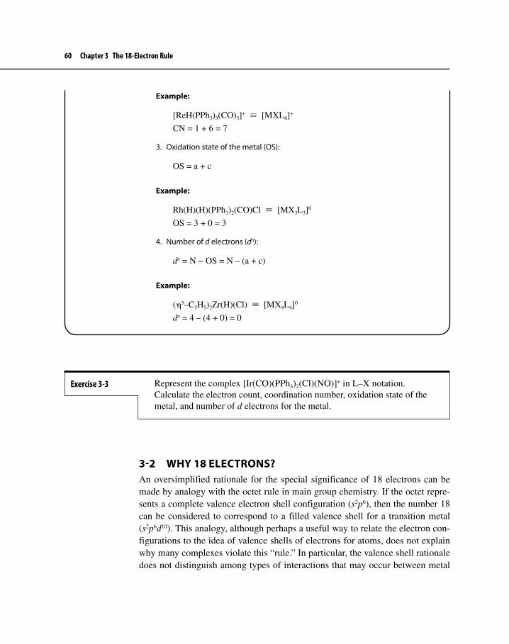
60 Chapter 3 The 18-Electron Rule
3-2 WHY 18 ELECTRONS?An oversimplified rationale for the special significance of 18 electrons can be made by analogy with the octet rule in main group chemistry. If the octet repre-sents a complete valence electron shell configuration (s2p6), then the number 18 can be considered to correspond to a filled valence shell for a transition metal (s2p6d10). This analogy, although perhaps a useful way to relate the electron con-figurations to the idea of valence shells of electrons for atoms, does not explain why many complexes violate this “rule.” In particular, the valence shell rationale does not distinguish among types of interactions that may occur between metal
Example:
[ReH(PPh3)3(CO)3]+ ≡ [MXL6]+
CN = 1 + 6 = 7
3. Oxidation state of the metal (OS):
OS = a + c
Example:
Rh(H)(H)(PPh3)2(CO)Cl ≡ [MX3L3]0
OS = 3 + 0 = 3
4. Number of d electrons (dn):
dn = N − OS = N – (a + c)
Example:
(η5–C5H5)2Zr(H)(Cl) ≡ [MX4L4]0
dn = 4 – (4 + 0) = 0
Exercise 3-3 Represent the complex [Ir(CO)(PPh3)2(Cl)(NO)]+ in L–X notation. Calculate the electron count, coordination number, oxidation state of the metal, and number of d electrons for the metal.

3-2 Why 18 Electrons? 61
and ligand orbitals; this distinction is an important consideration in determining which complexes obey the rule and which ones violate it.
3-2-1 Types of Metal–Ligand InteractionsMetal and ligand orbitals can interact in several ways. The type of interaction depends on the orientation of the orbitals with respect to each other. Most of these interactions can be classified into three types, based on the role of the ligands: σ donor, π donor, and π acceptor. These classifications are discussed in the follow-ing sections.
σ Donor LigandsThese ligands have an electron pair capable of being donated directly toward an empty (or partly empty) metal orbital. The following is an example of the interac-tion of a donor orbital of NH3, occupied by a lone pair of electrons, and an empty d orbital of suitable orientation on a metal.
NH3
M Sigma donor ligand
In a σ donor interaction, the electron pair on the ligand is stabilized by the forma-tion of a bonding molecular orbital, and the empty metal orbital (a d orbital in the example above) is destabilized in the formation of an antibonding orbital, as shown below.
d
σ
M Complex L

62 Chapter 3 The 18-Electron Rule
π Donor LigandsIn some cases, ligands may donate electrons in a π fashion, for example, using a filled p orbital as indicated below. Halide ions may participate in this type of interaction, with an electron pair donated in a π fashion to an empty metal d orbital (this d orbital must have a different orientation than the d orbital used in σ interactions).
M Pi donor ligand
L
The π donor interaction is in one respect similar to the σ donor case; the electron pair on the ligand is stabilized by the formation of a bonding molecular orbital, and the empty metal d orbital is destabilized in the formation of an antibonding orbital.
d
π
M Complex L
π Acceptor LigandsAlthough ligands are often thought of as donating electron pairs to metals, such is not always the case. For example, many types of ligands are known in which σ donation is complemented by the ability of a ligand to accept electron den-sity from a metal using suitable acceptor orbitals. The classic example of such a ligand is CO, the carbonyl ligand. The CO ligand can function as a σ donor using an electron pair in its highest occupied molecular orbital (HOMO), as shown on the next page.

3-2 Why 18 Electrons? 63
CM
Sigma donor orbital
O
Lobe of acceptor orbital
At the same time, CO has empty π* orbitals of suitable orientation to accept electron density from the metal.
M C O
CM O
The effect of the π acceptor interaction is the opposite of the σ interactions; an electron pair on the metal is now stabilized when a molecular orbital is formed, whereas the energy of the (empty) ligand orbital is destabilized as it becomes a higher energy (antibonding) molecular orbital.
d
π∗
M Complex L

64 Chapter 3 The 18-Electron Rule
These two ligand functions, σ donor and π acceptor, are synergistic. The more effective the σ donation, the greater the electron density on the metal. The result-ing electron-rich metal in turn is capable of donating electrons back to the ligand,56 which then acts as a π acceptor.
M C OSigma donor and piacceptor interactions
Examples of common ligands of all three types are given in Table 3-2. In many instances, ligands behave in more than one way. Hydroxide, for example, can be considered both a σ donor and a π donor, whereas a phosphine (PR3) is both a σ donor and a π acceptor.
3-2-2 Molecular Orbitals and the 18-Electron RuleOctahedral ComplexesAs we pointed out earlier in Chapter 3, Cr(CO)6 is a good example of a complex that obeys the 18-electron rule. The molecular orbitals of interest in this molecule are those that result primarily from interactions between the d orbitals of Cr and the σ donor (HOMO) and π acceptor orbitals (LUMO) of the six CO ligands. The molecular orbitals corresponding to these interactions are shown in Figure 3-1.7 (See Chapter 2, Figure 2-5, for a molecular orbital picture of CO.)
5
6This phenomenon is sometimes called “back-bonding” or “back-donation.”7Molecular orbitals are often designated by symmetry labels, such as the t2g and eg
* labels describing orbitals with significant d character in Figure 3-1. The method of assigning these labels is beyond the scope of this text. For further information on symmetry labels,
Table 3-2 Examples of Donor and Acceptor Ligands.
σ Donor π Donora π Acceptora
NH3 OH– COH2O Cl– CN–
H– RCO2– PR3
aThese ligands also act as σ donors.

3-2 Why 18 Electrons? 65
Figure 3-1 Molecular Orbitals of Cr(CO)6 (Only interactions between ligand (σ and π *) orbitals and metal d orbitals are shown.)Cr Cr(CO)6 6CO
d
eg∗
t2g
σ
π∗
Chromium(0) has six electrons outside its noble gas core. Each of the six CO ligands contributes a pair of electrons to give a total electron count of 18. In the molecular orbital energy level diagram these 18 electrons appear as the 12 σ electrons (the σ electrons of the CO ligands, stabilized by their interaction with the metal orbitals) and 6 metal–ligand bonding electrons (these electrons occupy orbitals having the symmetry label t2g).
Adding one or more electrons to Cr(CO)6 would populate metal–ligand anti-bonding orbitals (symmetry label eg
*); the consequence would be destabilization of the molecule. Removing electrons from Cr(CO)6 would depopulate the t2g orbitals. These are bonding in nature as a consequence of the strong π acceptor ability of the CO ligands; a decrease in electron density in these orbitals would also tend to destabilize the complex. The result is that the 18-electron configura-tion for this molecule is the most stable.
The shapes of the t2g and eg* orbitals support this description of bonding in
Cr(CO)6. One of the t2g orbitals is shown in Figure 3-2. An electron pair in this orbital spends the majority of its time in one of the four regions of overlap near the chromium as indicated in Figure 3-2 (these regions result from interaction of the dxy orbital of Cr with four π* orbitals of CO). Electrons in each of these regions would be expected to be attracted strongly by three nuclei, the chromium
see F. A. Cotton, Chemical Applications of Group Theory, 3rd ed., Wiley: New York, 1990, pp. 90–91.

66 Chapter 3 The 18-Electron Rule
Actual shape of π*CO
t2g
Cr
C
O
C
O
CO C O
π* of CO
dxy
Orbitals interacting
x
y
one regionof overlap
Figure 3-2A t2g Orbital of Cr(CO)6

3-2 Why 18 Electrons? 67
and two carbons; the resulting effect would be to hold these nuclei together, in effect keeping the CO ligands attached to the metal. The two other t2g orbitals have the same shape, but different orientations, than the one shown in Figure 3-2; these orbitals involve the dxz and dyz orbitals of the metal. Collectively, the electron pairs in the three t2g orbitals are crucial in bonding the six carbonyls to the chromium; in the absence of these electrons, the carbonyls would readily dissociate.
One of the eg* orbitals of Cr(CO)6 is shown in Figure 3-3. The principal
interaction in this case is antibonding between the σ orbitals of the carbonyls and the d orbital lobes of the chromium. Electrons in this orbital, or in the other eg
* orbital, would therefore destabilize the molecule, weakening Cr–CO bonds.
Continuing for the moment to consider 6-coordinate molecules of octahe-dral geometry, we can gain some insight as to when the 18-electron rule can be expected to be most valid. Cr(CO)6 obeys the rule because of two factors: the strong σ donor ability of CO raises the eg
* orbitals in energy, making them strongly antibonding; and the strong π acceptor ability of CO lowers the t2g orbit-als in energy, making them strongly bonding. Ligands that are both strong σ donors and π acceptors, therefore, should be the most effective at forcing adher-ence to the 18-electron rule. Other ligands, including some organic ligands, do not have these features and, consequently, their compounds may or may not adhere to the rule.
Examples of exceptions may be noted. [Zn(en)3]2+ is a 22-electron spe-cies; it has both the t2g and eg
* orbitals filled. Although en (ethylenediamine = NH2CH2CH2NH2) is a good σ-donor, it is not as strong a donor as CO. As a result, the eg
* orbital is not sufficiently antibonding to cause significant destabilization of the complex, and the 22-electron species, with 4 electrons in eg
* orbitals, is stable. An example of a 12-electron species is TiF6
2-. In this case, the fluoride ligand is a π donor as well as a σ donor. The π donor ability of F− destabilizes the t2g orbitals of the complex, making them slightly antibonding. The ion TiF6
2– has 12 electrons in the bonding σ orbitals and no electrons in the antibonding t2g or eg
* orbitals.These examples of exceptions to the 18-electron rule are shown schemati-
cally in Figure 3-4.8
Other GeometriesThe same type of argument can be made for complexes of geometries other than octahedral; in most, but not all cases there is an 18-electron configuration of special stability for complexes of strongly π accepting ligands. Examples include trigonal bipyramidal geometry [for example, Fe(CO)5] and tetrahedral geometry
8P. R. Mitchell and R. V. Parish, J. Chem. Ed., 1969, 46 , 311.

68 Chapter 3 The 18-Electron Rule
Figure 3-3An eg
* Orbital of Cr(CO)6
Cr
σ of CO
Orbitals interacting
x
y
C
O
C
O
CO C O
Actual shape of σCO
dx2-y2
eg*

3-3 Square Planar Complexes 69
[for example, Ni(CO)4]. The most common exception is square planar geometry, in which a 16-electron configuration may be the most stable, especially for com-plexes of d8 metals.
The relative energies of d orbitals of transition metal complexes can be pre-dicted approximately by the crystal field approach, a model of bonding that con-siders how the orbitals on a metal would interact with negative charges located at the sites of the ligands. By this model, the metal d orbitals pointing most directly toward the ligands will interact most strongly; electron pairs on the ligands will be stabilized, and a metal d orbital will be destabilized by such interactions. As a result, the more directly a d orbital points toward the ligands, the higher the energy of the resulting antibonding orbital.
For example, in octahedral geometry, the two d orbitals pointing most directly toward the ligands are the dx2–y2 and dz2. These metal orbitals interact more strongly with the ligands than the other d orbitals and give rise to the highest energy (anti-bonding) molecular orbitals (labeled eg
* ; see Figure 3-1). Similar reasoning can predict the relative energies of molecular orbitals derived from metal d orbitals for other geometries; examples of common geometries are shown in Figure 3-5.9
3-3 SQUARE PLANAR COMPLEXESChapter 9 discusses square planar complexes, which are particularly important in the field of catalysis. Examples include the d8, 16-electron complexes illustrated in Figure 3-6.
9Symbols such as a1, a1g, and b2g are additional symmetry labels useful in describing MOs with significant d character. See Footnote 7 in Chapter 3.
Figure 3-4Exceptions to the 18-Electron Rule (Although the six lowest energy MOs are shown as degenerate in the figure, this is an approximation that does not take into account interactions s and p orbitals of the metal.)M ML6 6L
d
eg∗
t2g
σ
Minimum of12 electrons
t2g nonbonding; fewerthan 18 electrons possible
eg∗ weakly antibonding; more
than 18 electrons possible

70 Chapter 3 The 18-Electron Rule
Figure 3-6 Examples of Square Planar d8 Molecules
Cl
Cl NH3
NH3
Pt
Cl
P PPh3
PPh3
Rh
Cl
P C
PPh3
Ir
C
C C
C
Ni
O
NN
N NPh3 Ph3
2–
Cisplatin Wilkinson's complex Vaska's complex
Figure 3-5 Relative Energies of Metal d Orbitals for Complexes of Common Geometries
M
L
L
L LL L ML L
L LM
L L
L L
Octahedral Square Planar Tetrahedral
eg
t2g
e
t2
eg
a1g
b1g
b2g
Ene
rgy
dz2 dx2–y2
dz2 dx2–y2
dxy dxz dyz
dxy dxz dyz
dx2–y2
dz2
dxy
dxz dyz
To understand why 16-electron square planar complexes might be especially stable, it is useful to examine the molecular orbitals of such a complex. An exam-ple of a molecular orbital energy level diagram for a square planar molecule of formula ML4 (L= ligand that can function as both s donor and π acceptor) is shown in Figure 3-7.
Four molecular orbitals of ML4 are derived primarily from the σ donor orbitals of the ligands; electrons occupying such orbitals are bonding in nature. Three additional orbitals are slightly bonding (derived primarily from dxz, dyz, and dxy orbitals of the metal) and one is essentially nonbonding (derived primarily from the dz
2 orbital of the metal). These bonding and nonbonding orbitals can be filled by 16 electrons. Additional electrons would occupy an antibonding orbital derived from the antibonding interaction of a metal dx
2–y2 orbital with the σ donor
orbitals of the ligands. Consequently, for square planar complexes of ligands hav-ing both σ donor and π acceptor characteristics, a 16-electron configuration may

Suggested Reading 71
Figure 3-7 Molecular Orbitals of Square Planar Complexes (Only σ donor and π acceptor interactions are shown.)M ML4 4L
d
dxy
σ
π∗
dxz, dyz
dz
dx –y2
2
2
be significantly more stable than an 18-electron configuration. Sixteen-electron square planar complexes may also be capable of accepting one or two ligands at the vacant coordination sites (along the z axis), thereby achieving an 18-electron configuration. As will be demonstrated in Chapter 7, this is a common reaction of 16-electron square planar complexes.
Verify that the complexes in Figure 3-6 are 16-electron species. Exercise 3-4
Sixteen-electron square planar complexes are most commonly found for d8 metals, in particular those metals having formal oxidation states of 2+ (Ni2+, Pd2+, Pt2+) and 1+ (Rh+, Ir+). Some of these complexes have important catalytic behavior, as discussed in Chapter 9.
Suggested Reading
General Background on the 18-Electron RuleP. R. Mitchell and R. V. Parish, J. Chem. Ed., 1969, 46, 811.W. B. Jensen, J. Chem. Ed., 2005, 82, 28.

72 Chapter 3 The 18-Electron Rule
More Recent Perspective and Related ConceptsP. Pyykkö, J. Organomet. Chem., 2006, 691, 4336.C. R. Landis, T. Cleveland, and T. K. Firman, J. Am. Chem. Soc., 1998, 120, 2641.D. Mingos and P. Michael, J. Organomet. Chem., 2004, 689, 4420.
Problems3-1 Octahedral transition metal complexes containing strong π acceptor
ligands obey the 18-electron rule much more often than complexes containing π donor ligands. Why?
3-2 Determine the valence electron counts on the transition metals.
a. [(η5-C5H5)2Co]+
b. Ir(CO)Cl(PMe3)2
c. [Fe(CO)4]2–
d. Rh(CO)(CS)(PPh3)2Br
3-3 Identify the first-row transition metal in the following 18-electron species.
a. (η4–C4H4)M(CO)3
b. [(η3–C3H5)M(CN)4]2–
c. (η3–C5H5)(η5–C5H5)M(CO)d. (η5–C5H5)M(NO) (has linear M–N–O)
3-4 Identify the second-row transition metal in the following 18-electron species.
a. [(η5–C5H5)M(CO)3]2 (has single M–M bond)b. [(η5–C5H5)M(CO)2]2 (has double M=M bond)c. [(η5–C5H5)M(CO)2(NO)]+ (has linear M–N–O)d. (η4–C8H8)M(CO)3
e. [M(CO)3(PMe3)]–
3-5 Identify the transition metal in the following 16-electron square planar species:
a. MCl(CO)(PPh3)2 (M = second-row transition metal)b. (CH3)2M(PPh3)2 (M = second-row transition metal)c. [MCl3(NH3)]– (M = third-row transition metal)
3-6 What charge, z, would be necessary for the following to obey the 18-electron rule?
a. [(η6–C6H6)2Ru]z
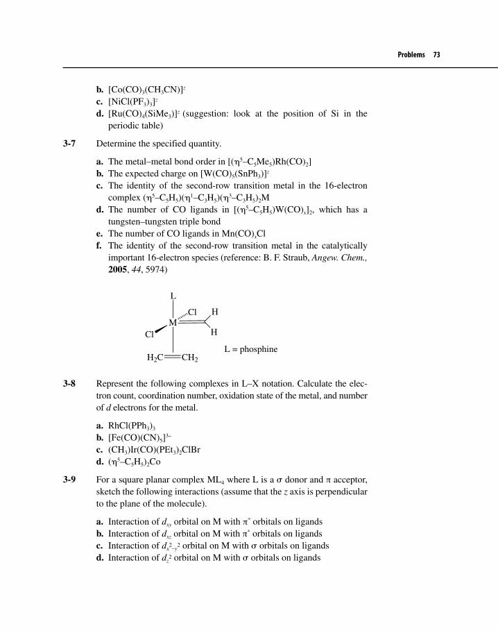
Problems 73
b. [Co(CO)3(CH3CN)]z
c. [NiCl(PF3)3]z
d. [Ru(CO)4(SiMe3)]z (suggestion: look at the position of Si in the periodic table)
3-7 Determine the specified quantity.
a. The metal–metal bond order in [(η5–C5Me5)Rh(CO)2]b. The expected charge on [W(CO)5(SnPh3)]z
c. The identity of the second-row transition metal in the 16-electron complex (η5–C5H5)(η1–C3H5)(η3–C3H5)2M
d. The number of CO ligands in [(η5–C5H5)W(CO)x]2, which has a tungsten–tungsten triple bond
e. The number of CO ligands in Mn(CO)xClf. The identity of the second-row transition metal in the catalytically
important 16-electron species (reference: B. F. Straub, Angew. Chem., 2005, 44, 5974)
M
L
Cl
H
H
C CH2
Cl
H2
L = phosphine
3-8 Represent the following complexes in L–X notation. Calculate the elec-tron count, coordination number, oxidation state of the metal, and number of d electrons for the metal.
a. RhCl(PPh3)3
b. [Fe(CO)(CN)5]3–
c. (CH3)Ir(CO)(PEt3)2ClBrd. (η5–C5H5)2Co
3-9 For a square planar complex ML4 where L is a σ donor and π acceptor, sketch the following interactions (assume that the z axis is perpendicular to the plane of the molecule).
a. Interaction of dxy orbital on M with π* orbitals on ligandsb. Interaction of dxz orbital on M with π* orbitals on ligandsc. Interaction of dx
2–y
2 orbital on M with σ orbitals on ligandsd. Interaction of dz
2 orbital on M with σ orbitals on ligands

74 Chapter 3 The 18-Electron Rule
3-10 What is the valence electron count for the blue ion NiCl42– ? Why does
this tetrahedral ion not obey the 18-electron rule?3-11 What is the valence electron count in (CH3)3Re(=O)2? Suggest a reason
why this compound does not obey the 18-electron rule. (See A. Haaland, W. Scherer et al., Organometallics, 2000, 19, 22.)

TWO
75
The carbonyl ligand, CO, is the most common ligand in organometallic chemistry. It may serve as the only ligand in binary carbonyls, such as Ni(CO)4, W(CO)6, and Fe2(CO)9, or, more commonly, in combination with other ligands, both organic and inorganic. CO may bond to a single metal or it may serve as a bridge between two or more metals. In Chapter 4 we consider the bonding between metals and CO, the synthesis and some reactions of CO complexes, and examples of the various types of CO complexes that form.
4-1 BONDINGIt is useful to begin by reviewing the bonding in CO itself. As described in Chapter 2 (Figure 2-5), the molecular orbital picture of CO is similar to that of N2 (Exercise 2-3); the molecular orbitals derived primarily from the 2p atomic orbitals of these molecules are illustrated in Figure 4-1.
4-1-1 CO as a Terminal LigandTwo features of the molecular orbitals of CO deserve particular attention. First, thehighest energy occupied orbital (the HOMO) has its largest lobe on carbon. It isthrough this orbital, occupied by an electron pair, that CO exerts its σ donor func-tion, donating electron density directly toward an appropriate metal orbital (suchas an unfilled p, d, or hybrid orbital). At the same time, CO has two empty π* orbit-als (LUMOs); these also have larger lobes on carbon than on oxygen. As a conse-quence of the localization of π* orbitals on carbon, the carbon acts as the principal
The Carbonyl LigandFOUR

76 Chapter 4 The Carbonyl Ligand
site of the π acceptor function of the ligand: a metal atom having electrons in a d orbital of suitable symmetry can donate electron density to these π* orbitals. These σ donor and π acceptor interactions are illustrated in Figure 4-2.
The overall effect is synergistic: CO can donate electron density via a σ orbital to a metal atom; the greater the electron density on the metal, the more effectively it is able to return electron density to the π* orbitals of CO. The net effect can be rather strong bonding between the metal and CO; however, as described later, the strength of this bonding is dependent on several factors, including the charge on the complex and the ligand environment of the metal.
Figure 4-1 Selected Molecular Orbitals of N2 and CO
σ
σ
π
π
∗
∗
CM O
Lobe of acceptor orbital
M C O
CM O
M C O
Sigma donation Pi acceptance Overall interaction
[Plus pi acceptance shown at left]
Figure 4-2σ and π Interactions between CO and a Metal Atom
Exercise 4-1 N2 has molecular orbitals slightly different from those of CO, as shown in Figure 4-1. Would you expect N2 to be a stronger or weaker π acceptor than CO?

4-1 Bonding 77
If this picture of bonding between CO and metal atoms is valid, it should be supported by experimental evidence. Two sources of such evidence are infrared spectroscopy (IR) and X-ray crystallography. First, any change in bonding between carbon and oxygen should be reflected in the C–O (carbonyl) stretching vibration as observed by IR. As in organic compounds, the C–O stretch in organometal-lic compounds is often intense (stretching the C–O bond results in a substantial change in dipole moment), and its energy often yields valuable information about the molecular structure. Free carbon monoxide has a C–O stretch at 2143 cm−1; Cr(CO)6, on the other hand, has its C–O stretch at 2000 cm−1. The lower energy for the stretching mode means that the C−O bond is weaker in Cr(CO)6.
The energy necessary to stretch a bond is proportional to km
, where
k = force constant, a measure of the rigidity of a bond µ = reduced mass; for atoms of mass m1 and m2 the
reduced mass is given by
µ = m m
m m
1 2
1 2+.
The stronger the bond between two atoms, the larger the force constant; consequently, the greater the energy necessary to stretch the bond and the higher the energy of the corresponding band (the higher the wave number, cm−1) in the infrared spectrum. Similarly, the more massive the atoms involved in the bond, as reflected in a higher reduced mass, the less energy necessary to stretch the bond and the lower the energy of absorption in the infrared spectrum.
Both σ donation (which donates electron density from a bonding orbital on CO) and π acceptance (which places electron density in CO antibonding orbitals) would be expected to weaken the C−O bond and to decrease the energy neces-sary to stretch that bond.
The charge on a carbonyl complex is also reflected in its infrared spectrum. Three isoelectronic hexacarbonyls have the following C−O stretching bands:1,2
Complex �(CO), cm−1
[V(CO)6]− 1858 [Cr(CO)6] 2000 [Mn(CO)6]+ 2095 (Free CO 2143)
1K. Nakamoto, Infrared and Raman Spectra of Inorganic and Coordination Compounds, 4th ed., Wiley: New York, 1986, pp. 292–293.2Positions of infrared absorptions may vary slightly depending on solvent, counterions, or other factors.

78 Chapter 4 The Carbonyl Ligand
Of these three, [V(CO)6]− has the metal with the smallest nuclear charge. Consequently, vanadium has the weakest ability to attract electrons and the great-est tendency to “back” donate electron density to CO. The consequence is strong population of the π* orbitals of CO and reduction of the strength of the C−O bond. In general, the more negative the charge on organometallic species, the greater the tendency of the metal to donate electrons to the π* orbitals of CO and the lower the energy of the C−O stretching vibrations.
Exercise 4-2 On the basis of the carbonyl complexes shown in the preceding table, predict the approximate position (in cm−1) of the C–O stretching band in [Ti(CO)6]2−.
Infrared Spectra of Carbonyl CationsLet’s examine one more series of isoelectronic transition metal carbonyl complexes:
Complex �(CO), cm−1
[W(CO)6] 1977 [Re(CO)6]+ 2085 [Os(CO)6]2+ 2190 [Ir(CO)6]3+ 2254
The same trend occurs as seen before: the more positive the charge in the com-plex, the less C–O backbonding and the higher the energy necessary to stretch C–O bonds. But how is it possible for C–O bands in carbonyl complexes to be stronger (have higher energy C–O stretches) than free CO, as in the cases of [Os(CO)6]2+ and [Ir(CO)6]3+? When the metal ion and CO interact in such metal carbonyls, the positive charge of the metal is believed to reduce the polarization of C–O molecular orbitals.3 The σ and π orbitals of CO in the free molecule are strongly polarized toward the much more electronegative oxygen atom. When a positively charged metal atom interacts with the carbon end of this molecule, the positive charge attracts electron density from the oxygen atom toward the carbon atom. The result is more covalent character in the carbon–oxygen bond and a stronger bond for the cationic complex than in free CO. The stronger this effect, the stronger the bond and the higher the energy of the C–O stretching vibration.
3A. J. Lupinetti, S. Fau, G. Frenking, and S. H. Strauss, J. Phys. Chem. A, 1997, 101, 9551 and R. K. Szilagyi and G. Frenking, Organometallics, 1997, 16, 4807. Additional aspects of bonding between transition metals and CO, using statistical data on metal–carbon and carbon–oxygen bond distances, are discussed in R. K. Hocking and T. W. Hambley, Organometallics, 2007, 26, 2815.

4-1 Bonding 79
Bond DistancesAdditional evidence on carbonyl ligand bonding to metals is provided by X-ray crystallography, which gives information on relative positions of atoms in mol-ecules. In carbon monoxide the C−O distance has been measured as 112.8 pm. Weakening of the C−O bond in carbonyl complexes by σ donation and π accep-tance would be expected to cause this distance to increase. Such an increase in bond length is found in complexes containing CO, with C−O distances of approximately 115 pm for many neutral carbonyl complexes. Although such measurements pro-vide definitive measures of bond distances, in practice it is far more convenient to use infrared spectra to obtain data on the strength of C−O bonds.4
4-1-2 Bridging Modes of COAlthough CO is most commonly found as a “terminal” ligand attached to a single metal atom, many cases are known in which CO forms bridges between two or more metals. Many such bridging modes are known; the most common are shown in Table 4-1 (on next page). Bridging ligands are designated using the Greek let-ter µ (mu), followed by a subscript indicating the number of atoms bridged. For example, µ2 indicates that a ligand bridges two atoms.
In addition to the symmetrical bridging modes of CO shown in Table 4-1, CO sometimes bridges metals asymmetrically; in these cases CO is considered semibridging (shown below).
A variety of factors can result in an asymmetric carbonyl bridge, including inherent asymmetry in molecules (such as CO bridging two or three different metals) and crowding (where moving of a CO away from a symmetrically bridg-ing position would help reduce crowding in part of a molecule).5
The bridging mode is strongly correlated with the position of the C−O stretch-ing band (Table 4-1). In cases where CO bridges two metal atoms, both metals can contribute electron density into π* orbitals of CO to weaken the C−O bond and lower the energy of the stretch. Consequently, the C−O stretch for doubly bridging
4Additional trends involving bond distances and charges in carbonyl complexes are discussed in R. K. Hocking and T. W. Hambley, Organometallics, 2007, 26, 2815.5For a discussion of various factors involved in asymmetrically bridging CO ligands, see F. A. Cotton and G. Wilkinson, Advanced Inorganic Chemistry, 5th ed., Wiley–Interscience: New York, 1988, pp. 1028–1032.
Semibridging Modes of CO
C
O
M MC
O
MMM

80 Chapter 4 The Carbonyl Ligand
CO is at a much lower energy than that for terminal carbonyls. For example, in Fe2(CO)9 there are three bridging and six terminal CO ligands (Figure 4-3). Infrared absorption caused by bridging carbonyls in this molecule occurs approximately 200 cm–1 lower than for terminal CO ligands; the bands for the terminal CO ligands in Fe2(CO)9 are similar to those reported for Fe(CO)5, 2034 and 2013 cm–1.6
Because the C–O bond is weaker in bridging CO ligands than in terminal COs, the carbon–oxygen bond in the bridging ligands is expected to be longer. This expectation is supported by the C–O bond distances in Fe2(CO)9 : 117.6 pm for the bridging ligands in comparison with an average of 115.6 pm for the terminal ligands.
6The infrared spectra and structures of Fe carbonyl complexes, with references to the original data, are discussed in J. H. Jang, J. G. Lee, H. Lee, Y. Xie, and H. F. Schaefer III, J. Phys. Chem. A, 1998, 102, 5298.
Table 4-1 Bonding Modes of CO
Type of COApproximate range for ν(CO) in neutralcomplexes (cm–1)
Terminal M−CO 1850–2120
Bridging Symmetrical µ2-CO 1700–1860
CM M
O
Symmetrical µ3-CO 1600–1700
C
O
MMM
µ4-CO Few examples are known; one is shown below.a
a P. Li and M. D. Curtis, J. Am. Chem. Soc., 1989, 111, 8279.
MoCp
S
CNiCp NiCp
MoS
Cp
1653 cm−1O
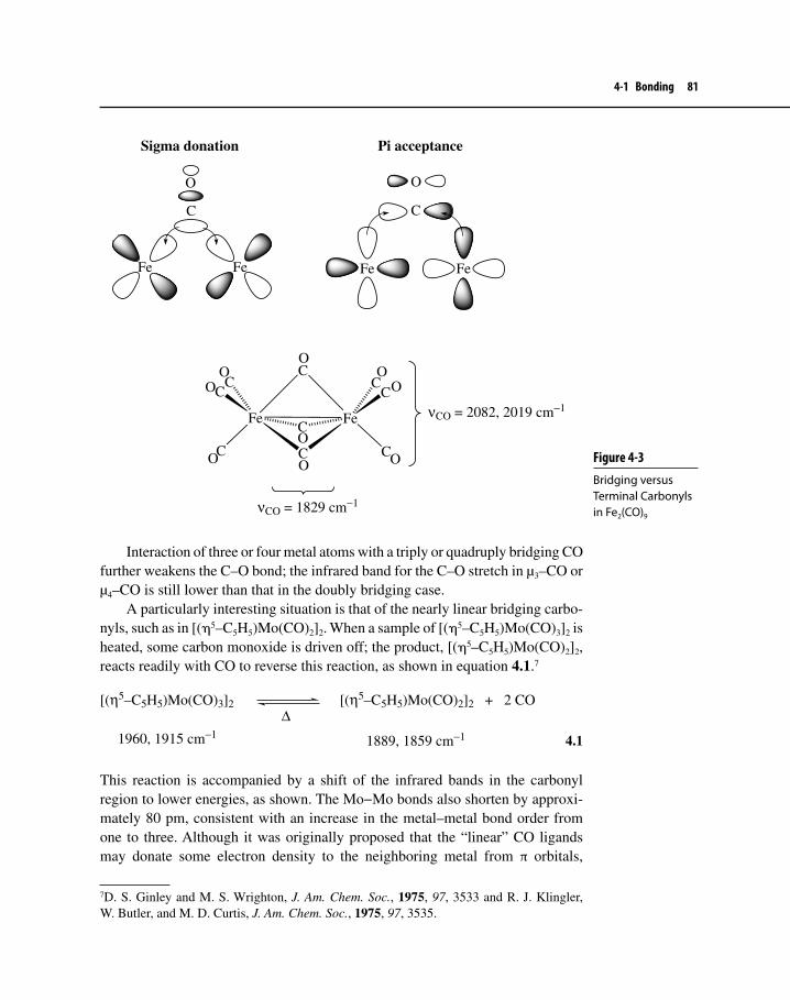
4-1 Bonding 81
Interaction of three or four metal atoms with a triply or quadruply bridging CO further weakens the C–O bond; the infrared band for the C–O stretch in µ3–CO or µ4–CO is still lower than that in the doubly bridging case.
A particularly interesting situation is that of the nearly linear bridging carbo-nyls, such as in [(η5–C5H5)Mo(CO)2]2. When a sample of [(η5–C5H5)Mo(CO)3]2 is heated, some carbon monoxide is driven off; the product, [(η5–C5H5)Mo(CO)2]2, reacts readily with CO to reverse this reaction, as shown in equation 4.1.7
[(η5–C [(η5–C5H5)Mo(CO)3]2∆
5H5)Mo(CO)2]2 + 2 CO
1960, 1915 cm−1 1889, 1859 cm−1
4.1
This reaction is accompanied by a shift of the infrared bands in the carbonyl region to lower energies, as shown. The Mo−Mo bonds also shorten by approxi-mately 80 pm, consistent with an increase in the metal–metal bond order from one to three. Although it was originally proposed that the “linear” CO ligands may donate some electron density to the neighboring metal from π orbitals,
7D. S. Ginley and M. S. Wrighton, J. Am. Chem. Soc., 1975, 97, 3533 and R. J. Klingler, W. Butler, and M. D. Curtis, J. Am. Chem. Soc., 1975, 97, 3535.
Figure 4-3 Bridging versus Terminal Carbonyls in Fe2(CO)9
Sigma donation Pi acceptance
C
O
C
O
Fe Fe Fe Fe
Fe
C
FeC
CC C
C CC C
OO
O
O
OO
O O
O
νCO = 2082, 2019 cm−1
νCO = 1829 cm−1

82 Chapter 4 The Carbonyl Ligand
subsequent calculations have indicated that a more important interaction is the donation from a metal d orbital to the π*. orbital of CO, as shown in Figure 4-4.8 Such donation weakens the C–O bond in the ligand and results in the observed shift of the C–O stretching bands to lower energy.
For purposes of electron counting, symmetrically bridging carbonyls, like terminal carbonyls, can most conveniently be counted as donating two electrons overall, with the electrons apportioned equally among the atoms bridged.9 For example, in Fe2(CO)9 (Figure 4-3) the electrons on either of the iron atoms can be counted as follows:
Fe 8 electrons Fe–Fe bond 1 electron 3 terminal COs 3 × 2 electrons = 6 electrons 3 µ2-CO 3 × 1–
2 × 2 electrons = 3 electrons 18 electrons
Additional examples of the utility of infrared spectra in characterizing carbonyl complexes are included in Section 4-5.
8A. L. Sargent and M. B. Hall, J. Am. Chem. Soc., 1989, 111, 1563, and references therein.9Triply bridging carbonyls also function as two-electron donors, formally two thirds of an electron per metal. In such cases it is often best to consider the two electrons donated to the complex as a whole rather than to specific metal atoms.
Figure 4-4 Bridging CO in [(η5–C5H5)Mo(CO)2]2
CO
Mo Mo
C
Mo
νCO = 1889, 1859 cm−1
O
CO
CC
O
O
Mo
Exercise 4-3 Determine the electron count of Co in the solid form of Co2(CO)8 (Figure 4-5 in the following section).

4-2 Binary Carbonyl Complexes 83
4-2 BINARY CARBONYL COMPLEXESBinary carbonyls, containing only metal atoms and CO, are fairly numerous. Structures of some representative binary carbonyl complexes are shown in Figure 4-5.
Most of these complexes obey the 18-electron rule. The cluster compounds Co6(CO)16 and Rh6(CO)16 do not obey the rule, however; more detailed analysis of the bonding in cluster compounds is necessary to satisfactorily account for the electron counting in these and other cluster compounds. This question is consid-ered in Chapter 13.
One other binary carbonyl does not obey the rule: the 17-electron V(CO)6. This complex, which is pyrophoric and much less thermally stable than the 18-electron Cr(CO)6, is one of a few cases in which strong π acceptor ligands do not succeed in requiring an 18-electron configuration. In V(CO)6 the vanadium is apparently too small to permit a seventh coordination site; hence, no metal–metal bonded dimer [which might potentially yield 18-electron (CO)6V–V(CO)6] is ordinarily possible.10 However, V(CO)6 is easily reduced to [V(CO)6]−, a well-studied 18-electron complex.
10In rare gas matrices and experiments involving laser photolysis, evidence has been reported for species that may contain two vanadiums and bridging carbonyls. See Z. Liu, Q. Li, Y, Xie, R. B. King, and H. F. Schaefer III, Inorg. Chem., 2007, 46, 1803, and references therein.
Figure 4-5Binary Carbonyl Complexes
M
•
•
•
M
C
C
C CC CO
O
O
O O
O
M
C
C
C
CC
O
O
O
O
OM
C
CC
C OOO
O
CoC
C
CC
O
O
OO
Co
C
C
CC
O
O
OO
Co
C
CC
O
OO
Co
CC
C
OO
OC COO
Fe
C
CC
O
OO
Fe
C C
C
O O
OC COO
CO
MC
C
CC
O
O
OO
M
C
C
CC
O
O
OO
C
C
O
O
M M
M
• •
••
•M M
M
• ••
••
•
Ir Ir
Ir
Ir
•
•M M
M
M
•
•
•
M
M
M
MM
•
•
Mononuclear
Binuclear
Polynuclear
M = Ni, Pd M = Fe, Ru, Os M = V, Cr, Mo, W
Co2(CO)8 (solid) Co2(CO)8 (solution)
Fe2(CO)9 M2(CO)10 [M = Mn, Tc, Re]
(• represents CO)
Fe3(CO)12 M3(CO)12 [M = Ru, Os]
M4(CO)12 [M = Co, Rh] Ir4(CO)12
M6(CO)16:[M = Co, Rh, Ir;triply bridging COligands on alternatefaces of octahedralcore; each M also has 2 terminal CO's]
••
••
•
•
•• ••
•
•
•
• •
•
••
••
•••
•••
• •
• •
•

84 Chapter 4 The Carbonyl Ligand
An interesting feature of the structures of binary carbonyl complexes is that the tendency of CO to bridge transition metals tends to decrease in moving down the periodic table from smaller metals to larger. For example, in Fe2(CO)9 there are three bridging carbonyls, but in Ru2(CO)9 and Os2(CO)9 there is a single bridging CO. Examples of the tendency of CO to act as a bridging ligand in first row transition metal complexes are also cited in later chapters.
4-2-1 SynthesisBinary carbonyl complexes can be synthesized in many ways. Several of the most common methods are described below.
1. Direct reaction of a transition metal with CO. The most facile of these reactions involves nickel, which reacts with CO at ambient temperature and 1 atm:
Ni + 4 CO Ni(CO)4 4.2
Ni(CO)4 is a volatile, toxic liquid that must be handled with great cau-tion. It was first observed by Mond, who found that CO reacted with nickel valves.11 The reverse reaction, involving thermal decomposition of Ni(CO)4, can be used to prepare nickel of high purity. Coupling of the forward and reverse reactions has been used commercially in the Mond process for obtaining purified nickel from ores.
Other binary carbonyls can be obtained from the direct reaction of metal powders with CO, but elevated temperatures and pressures are necessary.
2. Reductive carbonylation. In this procedure, a transition metal compound (with the metal in a positive oxidation state) is allowed to react with CO and a reducing agent. Examples:
CrCl3 + 6 CO + Al Cr(CO)6 + AlCl3 (catalyzed by AlCl3) 4.3
Re2O7 + 17 CO Re2(CO)10 + 7 CO2 (CO acts as reducing agent) 4.4
3. Thermal or photochemical reaction of other binary carbonyls. Examples:
Fe(CO)5 hν
Fe2(CO)9 (involves dissociation of CO) 4.5
11The original report by Mond [L. Mond, C. Langer, and F. Quincke, J. Chem. Soc. (London), 1890, 57, 749] is reprinted in J. Organomet. Chem., 1990, 383, 1.
Exercise 4-4 Verify the 18-electron rule for five of the binary carbonyls [other than Co6(CO)16 and Rh6(CO)16] shown in Figure 4-5.

4-2 Binary Carbonyl Complexes 85
Fe(CO)5 �
Fe3(CO)12 (involves dissociation of CO) 4.6
4-2-2 ReactionsDissociation of COThe most common reaction of carbonyl complexes is CO dissociation. This reaction, which may be initiated thermally or by absorption of ultraviolet light, characteristically involves a loss of CO from an 18-electron complex to give a 16-electron intermediate, which may react in a variety of ways depending on the nature of the complex and its environment. A common reaction is replacement of the lost CO by another ligand to form a new 18-electron species as product—a substitution reaction. The following are examples:12
Cr(CO)6 + PPh3 � or hν
Cr(CO)5(PPh3) + CO 4.7
Re(CO)5Br + en � fac-Re(CO)3(en)Br + 2 CO 4.8
Re
C
BrN CN C
Re
C
C
N BrN C
O
O
O
O
O
O
fac-ReBr(CO)3(en) mer-ReBr(CO)3(en)
This type of reaction, therefore, provides a pathway in which CO complexes can be used as precursors for a variety of complexes of other ligands. Additional aspects of CO dissociation reactions are discussed in later chapters.
Formation of Metal Carbonyl AnionsTransition metal carbonyl anions having charges of 1− through 4− are known. Originally such anions were prepared by the reaction of neutral metal carbonyls with bases, for example,13
Fe(CO)5 + 2 NaOEt Na2[Fe(CO)4] + OC(OEt)2 4.9
12The prefix fac designates a facial stereoisomer—in this case an octahedron with three CO groups at the corners of the same triangular face. Meridional isomers (abbreviated mer) cor-respond to stereoisomers in which three identical groups (e.g., COs) lie in the same plane.13The history of transition metal carbonyl anion synthesis, with extensive references, is described in J. E. Ellis, Organometallics, 2003, 22, 3322.

86 Chapter 4 The Carbonyl Ligand
Transition metal carbonyl anions are now synthesized primarily by the reduction of transition metal carbonyl compounds in donor solvents. For example, in liquid ammonia solvent Cr(CO)6 can be reduced by sodium to form the disodium salt of [Cr(CO)5]2– plus the explosive compound disodium acetylenediolate:
3 Na + Cr(CO)6 Na2[Cr(CO)5] + 1–2 NaOC≡CONa 4.10
The most commercially important metal carbonyl anion, [Fe(CO)4]2–, contained in Collman’s reagent (shown below), can be prepared from the following reaction in dioxane solvent.14
Fe(CO)5 + 2 Na[Ph2CO] � Na2[Fe(CO)4] • 3–2 dioxane + CO
(Collman’s reagent) 4.11
In solution, Na2[Fe(CO)4] can dissociate to yield anions such as [NaFe(CO)4]–
and species in which solvent molecules are attached to the anions. Collman’s reagent has broad applications in chemical synthesis.
The infrared spectra of transition metal carbonyl anions provide an excellent illustration of the effect on the charge of the π acceptor ability of CO; as expected, the more negative the charge, the stronger the π acceptance and the lower the energy of the C–O stretching vibrations (Table 4-2).
4-3 OXYGEN-BONDED CARBONYLSThis chapter would be incomplete without the mention of one additional aspect of CO as a ligand: it can sometimes bond through oxygen as well as carbon. This phenomenon was first noted in the ability of the oxygen of a metal carbonyl complex to act as a donor toward Lewis acids such as AlCl3, with the overall function of CO serving as a bridge between the two metals. Numerous examples are now known in which CO bonds through its oxygen to metal atoms, with
14J. P. Collman, R. G. Finke, J. N. Cawse, and J. I. Brauman, J. Am. Chem. Soc., 1977, 99, 2515.
Table 4-2 Positions of Strong C–O Absorptions in Binary Anionic Carbonyl Complexes
Charge Examples Range of C–O bands (cm–1)
1− [Co(CO)4]–, [Fe(CO)5]– 1852–19112− [Fe(CO)4]2–, [Ti(CO)6]2– 1730–17753− [Co(CO)3]3–, [V(CO)5]3– 1560–16904− [Cr(CO)4]4–, [Mo(CO)4]4– 1462–1478
Source: J. E. Ellis, Organometallics, 2003, 22, 3322.

4-4 Ligands Similar to CO 87
the C–O–metal arrangement generally bent. Attachment of a Lewis acid to the oxygen results in significant weakening and lengthening of the C−O bond. The result is a shift of the C–O stretching vibration to lower energy in the infrared. The magnitude of this shift is frequently between 100 and 200 cm−1 but may be greater. Examples of O–bonded carbonyls (sometimes called isocarbonyls) are shown in Figure 4-6. The physical and chemical properties of O–bonded carbonyls have been reviewed.15
4-4 LIGANDS SIMILAR TO COSeveral diatomic ligands similar to CO are worth brief mention. Two of these, CS (thiocarbonyl) and CSe (selenocarbonyl), are of interest in part for purposes of comparison with CO. Several other common ligands are isoelectronic with CO and, not surprisingly, exhibit structural and chemical parallels with CO. Two examples are CN− (cyanide) and N2 (dinitrogen). In addition, the NO (nitrosyl) ligand deserves discussion because of its similarities with CO. NS (thionitrosyl) and other ligands isoelectronic with NO also are considered briefly.
4-4-1 CS, CSe, and CTe ComplexesIn most cases, synthesis of CS (thiocarbonyl), CSe (selenocarbonyl), and CTe (tellurocarbonyl) complexes is somewhat more difficult than that for analogous CO complexes, since CS, CSe, and CTe do not exist as stable, free molecules and do not, therefore, provide a ready ligand source.16 Consequently, the compara-tively small number of such complexes should not be viewed as an indication of their stability; the chemistry of complexes of these three ligands may eventually rival that of CO complexes in breadth and utility. CS complexes are also of inter-est as possible intermediates in certain sulfur-transfer reactions in the removal of sulfur from natural fuels. In recent years, the chemistry of complexes containing
15C. P. Horwitz and D. F. Shriver, Adv. Organomet. Chem., 1984, 23, 219.16E. K. Moltzen, K. J. Klabunde, and A. Senning, Chem. Rev., 1988, 88, 391.
Figure 4-6 Oxygen-Bonded Carbonyls
WCC
CO Al(C6H5)3
O
O
1600 cm−1 Mo
C C
C O
O O
Mo
CC
CO
OO
Mg
N N
N
N
1667 cm−1

88 Chapter 4 The Carbonyl Ligand
these ligands has developed more rapidly as avenues for their synthesis have been devised.
CS, CSe, and CTe are similar to CO in their bonding modes; they behave as both σ donors and π acceptors and can bond to metals in terminal or bridging modes. Of these three ligands, CS has been studied the most closely. CS usually functions as a stronger σ donor and π acceptor than CO.17 The CTe ligand is rare, with only a handful of examples known. Nevertheless, a series of isoelectronic and isostructural complexes containing all four ligands, CO through CTe, was synthesized as early as 1980.18 These complexes and their C–E (E = element from group 16) stretching bands are listed in Table 4-3.
The decrease in C–E stretching energy in moving down this list is partly a consequence of increased reduced mass (Section 4-1-1) in going from oxygen to more massive outer atoms. In addition, the C–E bonds become progressively weaker moving down this series, a consequence of the general phenomenon that bonds between main group atoms tend to become weaker in descending the periodic table. In particular, π bonding is typically much weaker for elements found lower in the table (for example, Si=Si bonds are much weaker than C=C bonds). Consequently, C–S bonds are typically weaker than C–O bonds, and C–Se and C–Te bonds are even weaker. The C–O stretching bands in the series shown in Table 4-3 do not change significantly (complexes 2–4 all have bands near 2040 cm–1), suggesting that the overall interactions of these ligands with the osmium result in similar concentrations of electrons on the metal.
17P. V. Broadhurst, Polyhedron, 1985, 4, 1801.18G. R. Clark, K. Marsden, W. R. Roper, and L. J. Wright, J. Am. Chem. Soc., 1980, 102, 1206.
Table 4-3 Osmium Complexes Containing CO and Isoelectronic Ligands
Formula v(C–E) (cm–1)
(1) OsCl2(CO)2(PPh3)2 2040, 1975(2) OsCl2(CO)(CS)(PPh3)2 1315(3) OsCl2(CO)(CSe)(PPh3)2 1156(4) OsCl2(CO)(CTe)(PPh3)2 1046
OsCl
Cl C
C
PPh3
PPh3
E
O

4-4 Ligands Similar to CO 89
4-4-2 CN– and N2 ComplexesCyanide is a stronger σ donor and a somewhat weaker π acceptor than CO; over-all, it is similar to CO in its ability to interact with metal orbitals. Unlike most organic ligands, which bond to metals in low formal oxidation states, cyanide bonds readily to metals with higher oxidation states. As a good σ donor, CN− interacts strongly with positively charged metal ions; as a weaker π acceptor than CO (largely a consequence of the negative charge of CN− and the lower electro-negativity of N in comparison with O), cyanide is not as able to stabilize metals in low oxidation states. Therefore, its compounds are often studied in the con-text of “classical” coordination chemistry rather than organometallic chemistry. Dinitrogen is a weaker σ donor and π acceptor. However, N2 complexes are of great interest, especially as possible intermediates in reactions that may simulate natural processes of nitrogen fixation.19
4-4-3 NO ComplexesLike CO, the NO (nitrosyl) ligand is both a σ donor and a π acceptor and can be a terminal or bridging ligand; useful information can be obtained about its com-pounds by analysis of its infrared spectra. Unlike CO, however, terminal NO has two common coordination modes: linear (like CO) and bent. Useful information about the linear and bent bonding modes of NO is summarized in Figure 4-7.
A formal analogy is often drawn between the linear bonding modes of both ligands: NO+ is isoelectronic with CO; therefore, in its bonding to metals linear NO is considered NO+, a two-electron donor, by the donor pair (ionic) method (method A, Chapter 3). By the neutral ligand method (method B), linear NO is a three-electron donor (it has one more electron than the two-electron donor, CO).
The bent coordination mode of NO is often considered to arise formally from NO−, with the bent geometry suggesting sp2 hybridization at the nitrogen. By
19R. A. Henderson, G. J. Leigh, and C. J. Pickett, Adv. Inorg. Chem. Radiochem., 1983, 27, 197.
Figure 4-7Linear and Bent NO
N O N
O
M M
Linear Bent
M–N–O angle 165-180˚ 119-140˚ν(N–O) in neutral molecules 1620-1830 cm−1 1520-1720 cm−1
Electron donor count 2 (as NO+) 2 (as NO –)3 (as NO) 1 (as NO)

90 Chapter 4 The Carbonyl Ligand
electron counting method A, therefore, bent NO is considered the two-electron donor NO−; by the neutral ligand method it is considered a one-electron donor.
These views of bonding can be illustrated, as in Figure 4-8. In the neutral ligand model, which may be described as emphasizing the covalent nature of metal–ligand bonds, the electron configuration of NO is the starting point. NO has similar molecular orbitals to CO and one more electron, which occupies a π* orbital. When NO bonds in a bent fashion to a metal, the π* orbital interacts with a metal d orbital; if each of these orbitals has a single electron, a covalent bond between the ligand and metal is formed. In the linear coordination mode, the σ bonding orbital of NO, occupied by a pair of electrons, can donate this pair to a suitable empty orbital on the metal. In addition, the singly occupied π* orbital of NO can participate in covalent bonding with another d orbital on the metal. The result is the same type of synergistic σ donor-π acceptor bonding common in CO complexes.
In the donor pair model (method A), NO in the bent coordination mode is considered NO−. The nitrogen in NO− is considered sp2 hybridized and can donate an electron pair to a metal d orbital, as shown in Figure 4-8. In the linear mode, the ligand is considered NO+, with sp hybridization on nitrogen.20 An electron pair is donated through this hybrid. The metal (which is formally considered to have one more electron than in the covalent, neutral ligand case) can then donate an electron pair to an empty π* orbital on the ligand.
20In L–X notation, NO in a linear case is considered an LX ligand and in a bent case an X ligand. See M. L. H. Green, J. Organomet. Chem., 1995, 500, 127, for a discussion of this classification scheme.
Figure 4-8Covalent and Ionic Approaches to Bonding in NO Complexes
M
N O
M N O
Neutral Ligand Model (Covalent) Donor Pair Model (Ionic)
M N O
M
N Osp2
sp
NO–
NO+
Bent:
Linear:

4-4 Ligands Similar to CO 91
Numerous complexes containing each mode are known, and examples are also known in which both linear and bent NO occur in the same complex. Whereas linear coordination usually gives rise to N–O stretching vibrations at higher energy than in the bent mode, there is enough overlap in the ranges of these bands that infrared spectra alone may not be sufficient to distinguish between the two. Furthermore, the manner of packing in crystals may give rise to considerable bending of the metal−N−O bond from 180° in the “linear” coordination mode.
One compound containing only a metal and NO ligands is known:21 Cr(NO)4, a tetrahedral molecule isoelectronic with Ni(CO)4. Complexes containing bridg-ing nitrosyl ligands are also known, with the bridging ligand generally considered formally a 3-electron donor.
Sometimes NO plays more than one role in the same molecule; examples are shown in Figure 4-9.
4-4-4 NS and NSe Complexes
CrC
CNSO
O
In recent years, several dozen compounds containing the isoelectronic NS (thionitrosyl) ligand have been synthesized. Infrared data have indicated that, like NO, NS can function in linear, bent, and bridging modes. In general, NS is stronger than NO in its ability to act as a π acceptor ligand; the relative abilities of NO and NS to accept π electrons depend on the electronic environment of
21The term homoleptic has been coined to describe complexes in which all ligands are identi-cal. Cr(NO)4, Ni(CO)4, and W(CH3)6 are examples of homoleptic complexes.
Figure 4-9Examples of NO Playing Multiple Roles
RuN
Cl PPh3
N
O
OPh3P
138˚
178˚
Cr Cr
N
N
O
O
N
O
N
O

92 Chapter 4 The Carbonyl Ligand
the specific compounds being compared.22 Only a single NSe (selenonitrosyl) complex has been reported.23 Theoretical calculations are consistent with increas-ing metal–N bond order and decreasing N–E bond order in the series M–NO through M–NTe.24
4-5 IR SPECTRAIR spectra can be useful in two respects. The number of IR bands depends on molecular symmetry; consequently, by determining the number of such bands for a particular ligand (such as CO), one may be able to decide among several alter-native geometries for a compound—or at least reduce the number of possibilities. In addition, as we have seen, the position of the IR band can indicate the function of a ligand (for example, terminal vs. bridging modes) and, in the case of π accep-tor ligands, can describe the electron environment of the metal.
4-5-1 Number of IR BandsVibrational modes, to be IR-active, must result in a change in the dipole moment of the molecule. Not all vibrations give rise to a change in dipole moment; these consequently do not appear in the IR spectrum.
Carbonyl complexes provide convenient examples of vibrations that are vis-ible and invisible in the IR spectrum. Identical reasoning applies to other linear monodentate ligands (such as CN− and NO), and also to more complex ligands. We begin by considering several simple cases.
Monocarbonyl ComplexesThese complexes have a single possible C–O stretching mode. Consequently, they show a single band in the IR.
Dicarbonyl ComplexesTwo geometries, linear and bent, must be considered.
MCO C O
M
C
O
C
O
22H. W. Roesky and K. K. Pandey, Adv. Inorg. Chem. Radiochem., 1983, 26, 337.23T. J. Crevier, S. Lovell, J. M. Mayer, A. L. Rheingold, and I. A. Guzei, J. Am. Chem. Soc., 1998, 120, 6607.24C. M. Teague, T. A. O’Brien, and J. F. O’Brien, J. Coord. Chem., 2002, 55, 627, using the complexes CpCr(CO)2(NE), E = O, S, Se, and Te.

4-5 IR Spectra 93
In the case of two CO ligands arranged linearly, only an antisymmetric vibration of the ligands is IR-active; a symmetric vibrational mode results in no change in dipole moment and hence is inactive. If two COs are oriented in a nonlinear fash-ion, however, both symmetric and antisymmetric vibrations result in changes in dipole moment, and both are IR-active. These modes are shown below.
MCO C O
M
C
O
C
O
No change in dipole moment IR inactive
Change in dipole moment IR active
MCO C O
M
C
O
C
O
Change in dipole moment IR inactive
Change in dipole moment IR active
Therefore, an infrared spectrum can be a convenient tool for determining the structure for molecules known to have exactly two CO ligands: a single band indicates linear orientation of the carbonyls; two bands indicates nonlinear orientation.
Complexes Containing Three or More CarbonylsThe predictions in these cases are not quite so simple. The exact number of car-bonyl bands can be determined by the methods of group theory.25 For convenient reference, the numbers of bands expected for a variety of CO complexes are given in Table 4-4.
Several additional points relating to the number of infrared bands are worth noting. First, although one can predict the number of IR-active bands using Table 4-4, fewer bands may sometimes be observed. In some cases, bands may overlap to such a degree that they become indistinguishable; alternatively, one or more bands may have very low intensity and be difficult to observe. In some cases, iso-mers may be present in the same sample, and it may be difficult to sort out which
25G. L. Miessler and D. A. Tarr, Inorganic Chemistry, 3rd ed., Pearson Prentice Hall: Upper Saddle River, NJ, 2004, pp.103–110 and F. A. Cotton, Chemical Applications of Group Theory, 3rd ed., Wiley: New York, 1990, pp. 304–317 and 328–337.
Antisymmetric Stretch
Symmetric Stretch

94 Chapter 4 The Carbonyl Ligand
Table 4-4 Carbonyl Stretching Bandsa
aL = ligand other than CO.
M
C
L
L CL C
M
L
C
C LL C
M
L
L
C CC C
M
C
C
L CL C
M
L
C
C CC C
M
C
C
C CC C
O
OO
O
O
O
OOO
O
O
OO
O
OO
OO
O
O
O
O
O O
O
M
C
C
LL
M
L
L
CC
M
L
C
CL
M
L
CO
C
CC
M
C
L
C
CC
M
C
CO
C
CC
OO
O
O
O
O
OO
O
O
O
O
O
O
O
O
O
M
2 1 2
3
3
31 1
4 4
2 3
1
3
L
CC
C OOO
M
C
CC
C OOO
O
CO
CO
CO
Coordination number
4 5 6Numberof CO ligands
3
4
5
6
IR bands
IR bands
IR bands
IR bands
IR bands
IR bands
IR band

4-5 IR Spectra 95
IR absorptions belong to which compound. In carbonyl complexes the number of C−O stretching bands cannot exceed the number of CO ligands. The alterna-tive is possible in some cases (more CO groups than IR bands) when vibrational modes are not IR active (do not cause a change in dipole moment). Examples can be found in Table 4-2. The highly symmetric tetrahedral [M(CO)4] and octahe-dral [M(CO)6] complexes have a single carbonyl band in the IR spectrum. For a detailed survey of vibrational frequencies of transition metal carbonyl complexes, including cations and anions as well as neutral species, see footnote 26.26
4-5-2 Positions of Infrared BandsIn this chapter we have already encountered two examples in which the position of the carbonyl stretching band provides useful information. In the case of the isoelectronic species [Mn(CO)6]+, Cr(CO)6, and [V(CO)6]−, an increase in nega-tive charge on the complex causes a significant reduction in the energy of the C–O band as a consequence of additional π back bonding from the metal to the ligands. The bonding mode is also reflected in the infrared spectrum, with energy decreasing in the order
terminal CO > doubly bridging CO (μ2) > triply bridging CO (μ3).
The positions of infrared bands are also a function of other ligands present, as shown in the following examples.
Complex �(CO), cm–1
fac–Mo(CO)3(PF3)3 2074, 2026 fac–Mo(CO)3(PCl3)3 2041, 1989 fac–Mo(CO)3(PPh3)3 1937, 1841
Moving down this series, the σ donor ability of the phosphine ligands (PR3) increases, and the π acceptor ability decreases. PF3 is the weakest of the donors (as a consequence of the highly electronegative fluorines) and the strongest of the acceptors. As a result, the molybdenum in Mo(CO)3(PPh3)3 carries the greatest electron density; it is the most able to donate electron density to the π* orbitals of the CO ligands. Consequently, the CO ligands in Mo(CO)3(PPh3)3 have the weakest C−O bonds and the lowest energy stretching bands. Many comparable series are known.
The important point is that the position of the carbonyl bands can provide important clues to the electronic environment of the metal. The greater the electron density on the metal (and the greater the negative charge), the greater the back bonding to CO and the lower the energy of the carbonyl stretching
26 M. Zhou, L. Andrews, and C. W. Bauschlicher, Jr., Chem. Rev., 2001, 101, 1931.
96 Chapter 4 The Carbonyl Ligand
vibrations. Similar correlations between metal environment and infrared spectra can be drawn for a variety of other ligands, both organic and inorganic. NO, for example, has an infrared spectrum that is strongly correlated with environment in a manner similar to that of CO.27 In combination with information on the number of infrared bands, the positions of such bands for CO and other ligands can there-fore be extremely useful in characterizing organometallic compounds.
4-6 MAIN GROUP PARALLELS WITH BINARY CARBONYL COMPLEXESChemical similarities occur between main group and transition metal species that are “electronically equivalent” (i.e., species that require the same number of electrons to achieve a filled valence configuration).28 For example, a halogen atom, one electron short of a valence shell octet, may be considered electronically equivalent to Mn(CO)5, a 17-electron species one electron short of an 18-electron configuration. In this section we discuss briefly some parallels between main group atoms and ions and electronically equivalent binary carbonyl complexes.
Much of the chemistry of main group and metal carbonyl species can be rationalized from the way in which these species can achieve closed-shell (octet or 18-electron) configurations. These methods of achieving more stable configu-rations are illustrated for the following electronically equivalent species.
Electrons Examples of electronically equivalent speciesshort of � lled shell
Main group Metal carbonyl
1 Cl, Br, I Mn(CO)5, Co(CO)4
2 S Fe(CO)4, Os(CO)4
3 P Co(CO)3, Ir(CO)3
Halogen atoms, one electron short of a valence shell octet, exhibit chemical similarities with 17-electron organometallic species; some of the most striking are the parallels between halogen atoms and Co(CO)4, as summarized in Table 4-5. Both can reach filled-shell electron configurations by acquiring an electron or by dimerization to form either a Co−Co or a Cl−Cl bond. The neutral dimers are capable of adding across multiple carbon–carbon bonds and can undergo dispro-portionation by Lewis bases. Anions of both electronically equivalent species have a 1− charge and can combine with H+ to form acids: both HX (X = Cl, Br, or I) and
27Interpretation of infrared spectra of NO complexes is made more complicated, however, by the possibility of both bent and linear coordination modes of NO.28J. E. Ellis, J. Chem. Ed., 1976, 53, 2.
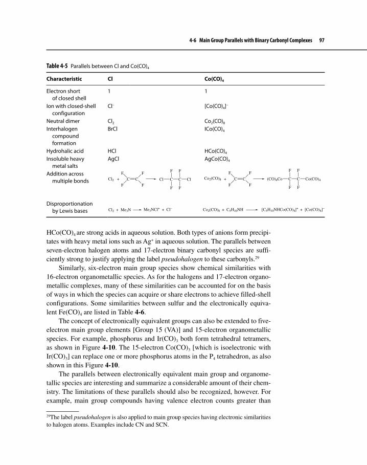
4-6 Main Group Parallels with Binary Carbonyl Complexes 97
Table 4-5 Parallels between Cl and Co(CO)4
Characteristic Cl Co(CO)4
Electron short of closed shell
1 1
Ion with closed-shell configuration
Cl– [Co(CO)4]–
Neutral dimer Cl2 Co2(CO)8
Interhalogen compound formation
BrCl ICo(CO)4
Hydrohalic acid HCl HCo(CO)4
Insoluble heavy metal salts
AgCl AgCo(CO)4
Addition across multiple bonds
Disproportionation by Lewis bases
HCo(CO)4 are strong acids in aqueous solution. Both types of anions form precipi-tates with heavy metal ions such as Ag+ in aqueous solution. The parallels between seven-electron halogen atoms and 17-electron binary carbonyl species are suffi-ciently strong to justify applying the label pseudohalogen to these carbonyls.29
Similarly, six-electron main group species show chemical similarities with 16-electron organometallic species. As for the halogens and 17-electron organo-metallic complexes, many of these similarities can be accounted for on the basis of ways in which the species can acquire or share electrons to achieve filled-shell configurations. Some similarities between sulfur and the electronically equiva-lent Fe(CO)4 are listed in Table 4-6.
The concept of electronically equivalent groups can also be extended to five-electron main group elements [Group 15 (VA)] and 15-electron organometallic species. For example, phosphorus and Ir(CO)3 both form tetrahedral tetramers, as shown in Figure 4-10. The 15-electron Co(CO)3 [which is isoelectronic with Ir(CO)3] can replace one or more phosphorus atoms in the P4 tetrahedron, as also shown in this Figure 4-10.
The parallels between electronically equivalent main group and organome-tallic species are interesting and summarize a considerable amount of their chem-istry. The limitations of these parallels should also be recognized, however. For example, main group compounds having valence electron counts greater than
29The label pseudohalogen is also applied to main group species having electronic similarities to halogen atoms. Examples include CN and SCN.
Cl2 + C C
F
F
F
FC C
F
F
Cl
F
Cl
F
Co2(CO)8 C C
F
F
F
F
C C
F
F
(CO)4Co
F
Co(CO)4
F
+
Cl2 + Me3N Me3NCl+ + Cl– Co2(CO)8 + C5H10NH [C5H10NHCo(CO)4]+ + [Co(CO)4]−
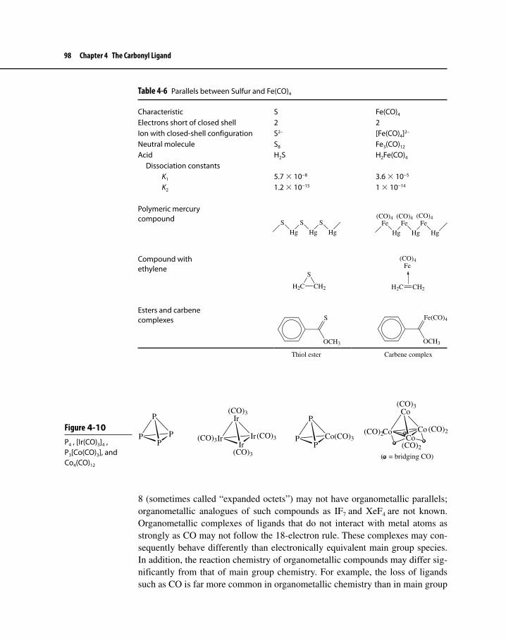
98 Chapter 4 The Carbonyl Ligand
Table 4-6 Parallels between Sulfur and Fe(CO)4
Characteristic S Fe(CO)4
Electrons short of closed shell 2 2Ion with closed-shell configuration S2– [Fe(CO)4]2–
Neutral molecule S8 Fe3(CO)12
Acid H2S H2Fe(CO)4
Dissociation constants K1 5.7 × 10⁻⁸ 3.6 × 10⁻⁵
K2 1.2 × 10⁻¹⁵ 1 × 10⁻¹⁴
Polymeric mercury compound
Compound with ethylene
Esters and carbene complexes
Ir Ir
Ir
Ir(CO)3
(CO)3
(CO)3
(CO)3
Co Co
Co
Co(CO)2
(CO)2
(CO)2
(CO)3
( = bridging CO)
P P
P
P P Co(CO)3
P
P
Figure 4-10 P4 , [Ir(CO)3]4 , P3[Co(CO)3], and Co4(CO)12
8 (sometimes called “expanded octets”) may not have organometallic parallels; organometallic analogues of such compounds as IF7 and XeF4 are not known. Organometallic complexes of ligands that do not interact with metal atoms as strongly as CO may not follow the 18-electron rule. These complexes may con-sequently behave differently than electronically equivalent main group species. In addition, the reaction chemistry of organometallic compounds may differ sig-nificantly from that of main group chemistry. For example, the loss of ligands such as CO is far more common in organometallic chemistry than in main group
S
Hg
S
Hg
S
HgFe
Hg
Fe
Hg
Fe
Hg
(CO)4(CO)4(CO)4
H2C CH2
S
H2C CH2
Fe(CO)4
OCH3
S
OCH3
Fe(CO)4
Thiol ester Carbene complex

Problems 99
chemistry. Therefore, as in any scheme based on a framework as simple as elec-tron counting, the concept of electronically equivalent groups, although useful, has its limitations. It serves as valuable background, however, for a potentially more versatile way to seek parallels between main group and organometallic chemistry—the concept of isolobal groups—to be discussed in Chapter 13.
Suggested Reading
Carbonyl and Other Complexes with Metals in Negative Oxidation StatesJ. E. Ellis, Inorg. Chem., 2006, 45, 3167.
Parallels with Main Group ChemistryJ. E. Ellis, J. Chem. Ed., 1976, 53, 2.
Bonding in CO ComplexesD. M. P. Mingos, “Bonding of Unsaturated Organic Molecules to Transition Metals,”
In Comprehensive Organometallic Chemistry, G. Wilkinson, F. G. A. Stone, and E. W. Abel, Eds., Pergamon Press: Oxford, 1982, Vol. 3, pp. 2–27.
NO ComplexesJ. A. Olabe and L. D. Slep, “Reactivity and Structure of Complexes of Small Molecules:
Nitric and Nitrous Oxide,” In Comprehensive Coordination Chemistry II, J. A. McCleverty and T. J. Meyer, Eds., Pergamon Press: Oxford, 2004, Vol. 1, pp. 603–623.
Problems4-1 V(CO)6 and [V(CO)6]– are both octahedral. Which has the shorter car-
bon–oxygen distance? The shorter vanadium–carbon distance?4-2 Predict the metal-containing products of the following reactions.
a. Mo(CO)6 + ethylenediamine [In this reaction two moles of gas are liberated for every mole of Mo(CO)6 reacting.]
b. V(CO)6 + NO [to give an 18-electron V complex]
4-3 Select the best choice in each of the following and briefly justify the reason for your selection.
a. Shortest C–O bond: Ni(CO)4 [Co(CO)4]– [Fe(CO)4]2–
b. Highest C–O stretching frequency: Ni(CO)3(PH3) Ni(CO)3(PF3)

100 Chapter 4 The Carbonyl Ligand
c. Strongest π acceptor ligand: NO– O2 O2– O2
2–
d. Shortest M–C bond: W(CO)6 [Re(CO)6]+ [Os(CO)6]2+ [Ir(CO)6]3+
4-4 In contrast to NO, few complexes of the phosphorus monoxide (PO) ligand have been reported.30 On the basis of what you know about NO as a ligand and on the relevant electron configurations, discuss possible ways in which PO might be likely to interact with transition metals. Be sure to include in your discussion the specific classification(s) of ligand–metal interactions most likely to occur.
4-5 When heated at low pressure, the compound (η5–C5Me5)Rh(CO)2 reacts to give a gas and another product having a single peak in the 1H-NMR and a single band near 1850 cm–1 in the infrared. Suggest a structure for this product.
4-6 The following questions concern the complex shown below.
M M
N N
M
NO
OO
NO
a. Identify the first-row transition metal.b. This complex shows infrared absorptions at 1320 and 1495 cm–1.
Account for these bands.c. Suppose each C5H5 ligand was replaced by C5Me5. Would you expect
the IR bands described in part b to shift to higher or lower energies? Why?
4-7 The ion [Ru(Cl)(NO)2(PPh3)2]+ has N–O stretching bands at 1687 and 1845 cm–1. The C–O stretching bands of dicarbonyl complexes are typically much closer than this in energy. Why are the N–O band fre-quencies so much farther apart?
4-8 Account for the observation that only a single carbonyl stretching band is observed for the ion [Co(CO)3(PPh3)2]+.
4-9 Remarkably, not until after more than a century of carbonyl chemistry were stable salts isolated containing the cations [M(CO)2]+ (M = Ag, Au)
30A. Bérces, et. al. Organometallics 2000, 19, 4336, and references therein.

Problems 101
and [M(CO)4]2+ (M= Pd, Pt).31 Where would you predict the carbonyl stretching bands in these ions to occur relative to other cationic carbonyl complexes?
4-10 An unusual bonding mode of the carbonyl ligand has carbon bridging two metals, whereas oxygen is bonded to a third.32 Would you predict the carbonyl stretching frequency in this bridging mode to be higher or lower than for ordinary doubly bridging CO ligands?
4-11 Photolysis of Fe2(CO)9 gives a product having IR bands at 2055, 2032, 2022, 1814, and 1857 cm–1. The product is less massive than Fe2(CO)9. Suggest a structure for this product.33
4-12 Predict the transition metal-containing product, an 18-electron species, of the following reaction.
Fe(CO)4I2 + n CN–
The product has two intense infrared bands. In addition, two weaker bands are also observed. No iodine is found in the product, and iron remains in its 2+ oxidation state. Finally, the product has the same num-ber of nitrogen and oxygen atoms.34
4-13 When molybdenum hexacarbonyl is refluxed in butyronitrile, C3H7CN, product X is formed first. Continued reflux converts X to Y, and very long reflux (several days) converts Y to Z.35 However, even refluxing for many weeks does not convert compound Z into another product. In addition,
In each step of reaction, a colorless gas is liberated.• X• , Y, and Z all follow the 18-electron rule.The following infrared bands are observed (cm• −1):
X: 2077 Y:36 2107 Z: 1910 1975 1898 1792 1938 1842
a. Propose (sketch) structures of X, Y, and Z.b. Suggest a reason why Z does not react further when refluxed in
butyronitrile.
31L. Weber, Angew. Chem. Int. Ed. Engl., 1994, 33, 1077.32R. D. Adams, Z. Li, J. C. Lii, and W. Wu, J. Am. Chem. Soc., 1992, 114, 4918.33S. C. Fletcher, M. Poliakoff, and J. J. Turner, Inorg. Chem., 1986, 25, 3597, provides origi-nal spectra of Fe2(CO)9 and this product.34J. Jiang and S. A. Koch, Inorg. Chem., 2002, 41, 158.35G. J. Kubas, Inorg. Chem. 1983, 22, 692.36A weak band in Y may be obscured by the other bands.
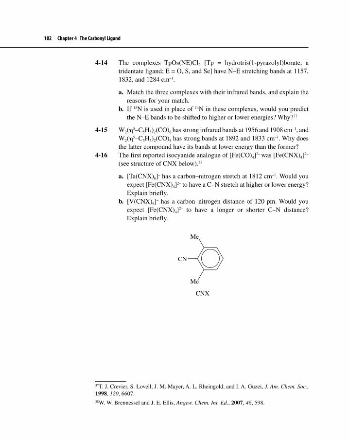
102 Chapter 4 The Carbonyl Ligand
4-14 The complexes TpOs(NE)Cl2 [Tp = hydrotris(1-pyrazolyl)borate, a tridentate ligand; E = O, S, and Se] have N–E stretching bands at 1157, 1832, and 1284 cm–1.
a. Match the three complexes with their infrared bands, and explain the reasons for your match.
b. If 15N is used in place of 14N in these complexes, would you predict the N–E bands to be shifted to higher or lower energies? Why?37
4-15 W2(η5–C5H5)2(CO)6 has strong infrared bands at 1956 and 1908 cm–1, and W2(η5–C5H5)2(CO)4 has strong bands at 1892 and 1833 cm–1. Why does the latter compound have its bands at lower energy than the former?
4-16 The first reported isocyanide analogue of [Fe(CO)4]2– was [Fe(CNX)4]2– (see structure of CNX below).38
a. [Ta(CNX)6]– has a carbon–nitrogen stretch at 1812 cm–1. Would you expect [Fe(CNX)4]2– to have a C–N stretch at higher or lower energy? Explain briefly.
b. [V(CNX)6]– has a carbon–nitrogen distance of 120 pm. Would you expect [Fe(CNX)4]2– to have a longer or shorter C–N distance? Explain briefly.
Me
Me
CN
CNX
37T. J. Crevier, S. Lovell, J. M. Mayer, A. L. Rheingold, and I. A. Guzei, J. Am. Chem. Soc., 1998, 120, 6607.38W. W. Brennessel and J. E. Ellis, Angew. Chem. Int. Ed., 2007, 46, 598.

TWO
103
Among the most distinctive aspects of organometallic chemistry is the ability of a wide variety of ligands containing π electron systems to form bonds to met-als. The most common of these π ligands are hydrocarbons, both linear (such as ethylene and butadiene) and cyclic (such as benzene and derivatives of the cyclo-propenyl group, C3H3); many π ligands containing “heteroatoms” such as sulfur, boron, and nitrogen are also known. In some cases, these π bonded ligands are far more stable when attached to metals than when free (some ligands are essentially unknown in the free state). In general, the ability of π ligands to undergo reac-tions is quite different than when these ligands are unattached to metals. Finally, the structures of many of these metal–π ligand complexes are striking, lending an almost artistic interest to this realm within organometallic chemistry.
In Chapter 5 we consider interactions between ligand π systems and metals, beginning with the simplest of the linear systems—ethylene—and then proceed-ing with more complex linear and cyclic systems. During this discussion, we pay special attention to the classic example of the compound ferrocene.
5-1 LINEAR PI SYSTEMS
5-1-1 π-Ethylene ComplexesMany complexes involve ethylene (C2H4) as a ligand, including the anion ofZeise’s salt, [Pt(η2–C2H4)Cl3]– (Figure 1-3)—one of the earliest organometalliccompounds to be synthesized. In such complexes, ethylene most commonly actsas a sidebound ligand with the following geometry with respect to the metal.
Pi LigandsFIVE

104 Chapter 5 Pi Ligands
Figure 5-1 Bonding in Ethylene Complexes
M M
π π∗
σ Donation π Acceptance
Acceptor lobe(may be from a d, p, or s orbital)
Ethylene donates electron density to the metal in a σ fashion, using its π bonding electron pair, as shown in Figure 5-1. At the same time, electron density can be donated back to the ligand in a π fashion from a metal d orbital to the empty π* orbital of the ligand. This is another example of the synergistic effect of σ dona-tion and π acceptance encountered earlier with the CO ligand.
This picture of bonding is in agreement with measured C–C distances. Free ethylene has a C–C distance of 133.7 pm, whereas the corresponding distance in the anion of Zeise’s salt is 137.5 pm. The lengthening of this bond can be explained by a combination of the two factors involved in the synergistic σ donor–π acceptor nature of the ligand: (a) donation to the metal in a σ fashion reduces the electron density in a filled π bonding orbital within the ligand, weak-ening the C–C bond; (b) the back-donation from the metal to the π* orbital of the ligand also reduces the C–C bond strength by populating this antibonding orbital. The net effect weakens and hence lengthens the C–C bond in the C2H4 ligand.
5-1-2 π–Allyl ComplexesThe allyl group can function as a trihapto ligand: using delocalized π orbitals as described previously; as a monohapto ligand, primarily σ bonded to a metal; or as a bridging ligand. Examples of these types of coordination are shown in Figure 5-2.
Bonding between η3–C3H5 and a metal atom is shown schematically in Figure 5-3. The lowest energy π orbital (Figure 2-8) can donate electron density to a suitable orbital on the metal (the bottom interaction illustrated in Figure 5-3). The next orbital, nonbonding in free allyl, can act as a donor or acceptor, depend-ing on the electron distribution between the metal and the ligand; frequently, its
C
C
H
H
H
H
Pt

5-1 Linear Pi Systems 105
Figure 5-2 Examples of Allyl Complexes
Ni Pd Pd
Cl
Cl
Mn
C
C
C CH2
C C
O
O
O
O
O
Mo Mo
η3–C3H5:
η1–C3H5: Bridging C3H5:
Ph
Ph
Figure 5-3Bonding in η3–Allyl Complexes
M
M
M
Other metal orbitalswith suitable symmetry
px
dyz
dz2, s
dxz
py
pz
Relative energyof allyl orbitals
π
πn
π∗
z
x
y
primary function is as a filled donor orbital. The empty, highest energy π orbital acts as an acceptor; thus, there can be synergistic σ and π interactions between allyl and the metal. In π–allyl complexes the carbon–metal distances reflect the overall environment of the metal. Whereas in the majority of cases the central carbon is closer to the metal than the end carbons, in some cases the reverse is true. The C–C–C angle within the ligand is generally near 120o, consistent with sp2 hybridization on the central carbon.
Allyl complexes (or complexes of substituted allyls) are intermediates in many reactions—some of which take advantage of the capacity of this ligand to function

106 Chapter 5 Pi Ligands
in both an η3 and an η1 fashion. Loss of CO from carbonyl complexes containing η1– allyl ligands often results in conversion of η1– to η3– allyl. For example,
∆ or hν[Mn(CO)5]– C3H5Cl (η1–C3H5)Mn(CO)5 (η3–C3H5)Mn(CO)4+
+ Cl– + CO
5.1
(Note that all manganese-containing species in this sequence of reactions are 18-electron species. The mechanism of this reaction is discussed in Chapter 7, Section 7-2-2.)
5-1-3 Other Linear π SystemsMany other such systems are known. Several examples of organic ligands hav-ing longer π systems are shown in Figure 5-4. Butadiene and longer conjugated
Figure 5-4 Examples of Molecules Containing Linear π Systems
Mo(CO)3
HH
Zr
PMe2
PMe2
H
s-cis-Butadiene Complex
Zr
s-trans-Butadiene Complex
CH3
H3C
FeH3C
H3C
Ti
Ti
Os(CO)3
Ni
1,3-COD Complex 1,5-COD Complex

5-2 Cyclic π Systems 107
π systems have the possibility of isomeric ligand forms (s-cis and s-trans for butadiene). Larger cyclic ligands may have a π system extending through part of the ring. An example is cyclooctadiene (COD): the 1,3-isomer has a four-atom π system comparable to butadiene; 1,5-cyclooctadiene has two isolated double bonds, one or both of which may interact with a metal in a manner similar to ethylene. A schematic diagram outlining the metal–ligand interactions for a cis-butadiene complex is shown in Figure 5-5.
5-2 CYCLIC π SYSTEMS
5-2-1 Cyclopentadienyl (Cp) ComplexesThe cyclopentadienyl group, C5H5, may bond to metals in a variety of ways, with examples known of the η1– and η3– modes, as well as the most common η5– bonding mode, shown below. As described in Chapter 1, the discovery of the first cyclopentadienyl complex, ferrocene, was a landmark in the development of organometallic chemistry and stimulated the search for other compounds contain-ing π-bonded organic ligands. Numerous substituted cyclopentadienyl ligands are also known, such as C5(CH3)5 (often abbreviated Cp*) and C5(benzyl)5.1
1Common abbreviations for cyclopentadienyl ligands include Cp = C5H5, Cp* = C5Me5, and Cp′ = C5EtMe4.
Figure 5-5Bonding in s-cis-Butadiene Complexes
M
M
M
Other metal orbitalswith suitable symmetry
px
dyz
dz2, s
dxz
py
pz
Relative energyof butadiene orbitals
M
z
x
y
dxy

108 Chapter 5 Pi Ligands
WC
CO
OTi Fe
Cl
CC
OO
η5–C5H5
η3–C5H5
η1–C5H5
Ferrocene
Fe
Ferrocene is the prototype of a series of sandwich compounds, called the metal-locenes, with the formula (C5H5)2M. The bonding in ferrocene can be viewed in a variety of ways. One possibility is to consider it an iron(II) complex with two cyclopentadienide (C5H5
–) ions, while another is to view it as iron(0) coor-dinated by two neutral C5H5 ligands. The actual bonding situation in ferrocene is much more complicated and requires an analysis of the various metal–ligand interactions in this molecule. As usual, orbitals on the central Fe and on the two C5H5 rings interact if they are of appropriate symmetry; furthermore, we expect interactions to be strongest if they are between orbitals of similar energy.
Figure 2-11 in Chapter 2 illustrates sketches of the molecular orbitals of a C5H5 ring; two of these rings are arranged in a parallel fashion in ferrocene to “sandwich in” the metal atom. The following discussion is based on the eclipsed conformation of ferrocene, the conformation consistent with gas phase and low-temperature data on this molecule.2,3 Theoretical calculations also indicate that the eclipsed conformation has slightly lower energy than the staggered form.4 Descriptions of the bonding in ferrocene based on the staggered geometry are common in the chemical literature, because this was once believed to be the molecule’s most stable conformation.5
2A. Haaland and J. E. Nilsson, Acta Chem. Scand., 1968, 22, 2653; see also A. Haaland, Acc. Chem. Res., 1979, 12, 415.3P. Seiler and J. Dunitz, Acta Crystallogr. Sect. B, 1982, 38, 1741.4S. Coriani, A. Haaland, T. Helgaker, and P. Jørgensen, ChemPhysChem, 2007, 7, 245, and references cited therein.5The C5(CH3)5 and C5(benzyl)5 analogs of ferrocene do have staggered geometries, as do several other metallocenes; see M. D. Rausch, W-M. Tsai, J. W. Chambers, R. D. Rogers, and H. G. Alt, Organometallics 1989, 8, 816, for some examples.

5-2 Cyclic π Systems 109
The group orbitals are derived from the π orbitals of the two C5H5 rings by pairing C5H5 orbitals of the same energy and same number of nodes, for example, pairing the zero-node orbital of one ring with the zero-node orbital of the other.6 The molecular orbitals must be paired in such a way that the nodal planes are coincident. Furthermore, in each pairing there are two pos-sible orientations of the ring molecular orbitals: one in which lobes of like sign are pointed toward each other and one in which lobes of opposite sign are pointed toward each other. For example, the zero-node orbitals of the C5H5 rings may be paired in the following ways to generate two of the group orbitals.
Orbital lobes oflike sign pointed toward each other
Orbital lobes ofopposite sign pointed
toward each other
The ten group orbitals arising from the C5H5 ligands are shown in Figure 5-6. Note that the two π systems for each group orbital do not interact directly with each other.
The process of developing the molecular orbital picture of ferrocene now becomes one of matching the group orbitals with the s, p, and d orbitals of appro-priate symmetry on Fe.
Determine which orbitals on Fe are appropriate for interaction with each of the group orbitals in Figure 5-6.
Exercise 5-1
6Not counting the nodal planes that are coplanar with the C5H5 rings.

110 Chapter 5 Pi Ligands
dyz
x
y
z
Bonding Antibonding 1 2
We illustrate one of these interactions: the interaction between the dyz orbital of Fe and its appropriate group orbital (one of the one-node group orbitals shown in Figure 5-6). This interaction can occur in a bonding and an antibonding fashion, as shown below.
Figure 5-6 Group Orbitals for the C5H5 Ligands of Ferrocene
2-Node Group Orbitals
1-Node Group Orbitals
0-Node Group Orbitals

5-2 Cyclic π Systems 111
In the bonding orbital resulting from interaction 1, the lobes of the dyz orbital of iron merge with the lobes of the group orbital to which they point, giving the striking appearance illustrated in Figure 5-7.
The nodal behavior of the interacting metal and group orbitals must be preserved in the molecular orbitals that result. Thus, the molecular orbital in Figure 5-7 must have two nodal planes, the same as those of the original dyz orbital: the xy plane (shown horizontally in Figure 5-7) and the xz plane (cut-ting vertically through the molecule in Figure 5-7). The antibonding interaction 2 gives the molecular orbital shown in Figure 5-8.
The complete energy-level diagram for the molecular orbitals of ferrocene is shown in Figure 5-9. The molecular orbital resulting from the dyz bonding interaction, labeled 1 in Figure 5-9, contains a pair of electrons. Its antibonding counterpart, 2, is empty. It is a useful exercise to match the other group orbitals from Figure 5-6 with the molecular orbitals in Figure 5-9 to verify the types of metal–ligand interactions that occur.
The most interesting orbitals of ferrocene are those having the greatest d orbital character; these are highlighted in the box in Figure 5-9. Two of these orbitals, having largely dxy and dx2–y2 character, are weakly bonding and are occu-pied by electron pairs; one, having largely dz2 character, is essentially non-bonding and occupied by one electron pair; and two, having primarily dxz and dyz character,
Figure 5-7 Bonding Molecular Orbital Formed from dyz Orbital of Iron in Ferrocene
z
y
x

112 Chapter 5 Pi Ligands
are empty. The relative energies of these orbitals and their d orbital–group orbital interactions are illustrated in Figure 5-10.7,8
The overall bonding in ferrocene can now be summarized. The occupied orbitals of the cyclopentadienyl ligands—the zero-node and one-node group orbitals—are stabilized by their interactions with iron. In addition, six electrons occupy molecular orbitals that are largely derived from iron d orbitals (as one would expect for d6 iron(II)), but these occupied orbitals, displayed in Figure 5-10, have significant ligand character too. The molecular orbital picture in this
7The relative energies of the lowest three orbitals shown in Figure 5-10 have been controversial. UV photoelectron spectroscopy indicates that the order is as shown, with the orbital having largely dz2 character slightly higher in energy than the degenerate pair having substantial dxy and dx2–y2 character. This order may be reversed for some metallocenes. (See A. Haaland, Accts. Chem. Res., 1979, 12, 415.) A recent report (Z. Xu, Y. Xie, W. Feng, and H. F. Schaefer III, J. Phys. Chem. A, 2003, 107, 2716) places the orbital having dz2 character lower in energy than the degenerate pair and discusses the energy levels for the metallocenes (η5-C5H5)2V through (η5-C5H5)2Ni.8J. C. Giordan, J. H. Moore, and J. A. Tossell, Acc. Chem. Res., 1986, 19, 281; E. Rühl and A. P. Hitchcock, J. Am. Chem. Soc., 1989, 111, 5069.
Figure 5-8 Antibonding Molecular Orbital Formed from dyz Orbital of Iron in Ferrocene
z
y
x

5-2 Cyclic π Systems 113
4p
4s
3d
0-node
1-node
2-node
dyz dxz
dz2
pz
pypx
pz
s
dx2-y2dxy
(nonbonding)
dyz dxz
px py
dxy dx2-y2
s, dz2
Fe Fe
Group Orbitals
1
2
Figure 5-9 Molecular Orbital Energy Levels in Ferrocene
case is consistent with the 18-electron rule; however, as is evident in other metal-locenes, the cyclopentadienyl ligand is not as effective as other ligands, notably CO, at favoring the 18-electron arrangement.
Other MetallocenesOther metallocenes have similar structures but do not necessarily obey the 18-electron rule. For example, cobaltocene, (η5–C5H5)2Co, and nickelocene, (η5–C5H5)2Ni, are structurally similar 19- and 20-electron species. The “extra”

114 Chapter 5 Pi Ligands
Figure 5-10 Molecular Orbitals of Ferrocene Having Greatest d Character*The three highest energy orbitals are antibonding; the corresponding bonding interactions have lower energy; see Figure 5-9.
dz2*
dxy dx2-y2
dyz* dxz
*
2
electrons have important chemical and physical consequences, as seen in comparative data in Table 5-1.9
The increase in metal–carbon distance in moving down this series is impor-tant because it is counter to the trend that radii of transition metal atoms and ions decrease from Sc through Ni. The explanation is that the 19th and 20th electrons of the metallocenes occupy antibonding orbitals (Figure 5-9). As a consequence, the metal–ligand distance increases (the ligands in cobaltocene and nickelocene are less tightly held to the metal), and ∆H for metal–ligand dissociation decreases.
9See Footnote 2.

5-2 Cyclic π Systems 115
The number of unpaired electrons in these three metallocenes is also consistent with the picture of bonding shown in Figure 5-9.
Would you predict the metal–carbon distances in (η5–C5H5)2V and (η5–C5H5)2Cr to be longer or shorter than in ferrocene?
Exercise 5-2
Ferrocene itself shows much more chemical stability than cobaltocene and nickelocene; many of the chemical reactions of the latter are characterized by a tendency to yield 18-electron products. For example, ferrocene is unreactive toward iodine and rarely participates in reactions in which other ligands sub-stitute for the cyclopentadienyl ligand. However, cobaltocene and nickelocene undergo the following reactions to give 18-electron products.
2 (η5–C5H5)2Co + I2 2 [(η5–C5H5)2Co]+ + 2 I – 19 e– 18 e–
cobalticinium ion 5.2(η5–C5H5)2Ni + 4 PF3 Ni(PF3)4 + organic products 20 e– 18 e– 5.3
Interestingly, cobalticinium, [(η5–C5H5)2Co]+, reacts with hydride to give a neutral, 18-electron sandwich compound in which one cyclopentadienyl ligand has been modified into η4-C5H6, as shown in Figure 5-11.
Ferrocene, however, is by no means chemically inert. It undergoes a variety of reactions, including many on the cyclopentadienyl rings. A good example is
Figure 5-11 Reaction of Cobalticinium with Hydride
CoCo + H–
+
Table 5-1 Ferrocene, Cobaltocene, and Nickelocene
∆H for M2+ – C5H5–
Dissociation (kcal/mol)Complex Color CountUnpaired electrons M–C Distance (pm)
(η5–C5H5)2Fe Orange 18 0 206.4 351(η5–C5H5)2Co Purple 19 1 211.9 335(η5–C5H5)2Ni Green 20 2 219.6 315

116 Chapter 5 Pi Ligands
electrophilic acyl substitution (Figure 5-12), a reaction paralleling Friedel–Crafts acylation of benzene and its derivatives. In general, electrophilic aromatic substi-tution reactions are much more rapid for ferrocene than for benzene, an indica-tion of a greater concentration of electron density in the rings of the sandwich compound than in benzene.
Manganocene, (η5–C5H5)2Mn, has an unusually long metal–carbon distance, 238.0 pm. This is because manganocene is a high spin complex; each orbital in the box in Figure 5-10 has a single unpaired electron. Because two of these elec-trons are in antibonding orbitals and each bonding orbital is just singly occupied, the manganese–carbon bonds are longer and weaker than that of the other metal-locenes in the series (η5–C5H5)2V through (η5–C5H5)2Ni.
One of the most remarkable of all metallocenes is an ion that does not contain carbon at all! This complex, [Ti(η5–P5)2]2–, illustrated in Figure 5-13, was syn-thesized by reacting [Ti(CO)6]2- with white phosphorus, P4; it represents the first “all-inorganic” metallocene.10
[Ti(CO)6]2– + 2.5 P4 [Ti(η5–P5)2]2– + 6 CO 5.4
10E. Urnezius, W. W. Brennessel, C. J. Cramer, J. E. Ellis, and P. v. R. Schleyer, Science, 2002, 295, 832.
Figure 5-13 Structure of [Ti(η5–P5)2]2–
Ti
PP
PP
P
PP
PP
P2–
Figure 5-12 Electrophilic Substitution with Acylium Ion on Ferrocene
FeFe
H
O
CH3
+
– H+Fe
O
CH3
H3CC O+

5-2 Cyclic π Systems 117
Figure 5-14 Complexes Containing C5H5 and CO
V(CO)4 Mn(CO)3TiC
CO
O
V CO
FeC
CO
O
Mo CO
Fe
CO
Fe
COC
C
O
O
CrCO
CrCO
C
C
C
CO
O
OO
Re Re
C
C
C
CO
O
OO
CO
Os Os
C
C
C
CO
O
OO
Mo
C
Mo
O
C O
CC
OO
Group 4 Group 5 Group 6 Group 7
Group 8 Group 9 Group 10 Group 11
Cu COCo CCO
O
Ni NiC
CO
O
Co Co
C
C
O
O
Similar structures for Zr, Hf Similar structures for Nb, Ta Similar structure for W
Similar structures for Mo, W
Similar structure for Cr
Similar structure for Ru
Similar structures for Tc, Re
5-2-2 Complexes Containing Cyclopentadienyl and CO LigandsNot surprisingly, many complexes containing both Cp and CO ligands are known. These include “half sandwich” compounds such as (η5–C5H5)Mn(CO)3 and dimeric and larger cluster molecules. Selected examples are illustrated in Figure 5-14. As

118 Chapter 5 Pi Ligands
for the binary CO complexes, complexes of the second- and third-row transition metals demonstrate a decreasing tendency of CO to act as a bridging ligand.
5-2-3 Other Cyclic π LigandsMany other cyclic π ligands are known. The most common cyclic hydrocar-bon ligands are listed in Table 5-2. Depending on the ligand and the electron requirements of the metal (or metals), these ligands may be capable of bonding in a monohapto or polyhapto fashion, and they may bridge two or more metals. The different sized rings have interesting features and are worth a brief survey.
Table 5-2 Cyclic π Ligands
Electron count
Formula Structure Name Method Aa Method B
C3H3 Cyclopropenyl R = alkyl, phenyl
2 (C3R3+) 3
C4H4 Cyclobutadiene 6 (C4H42–) 4
C5H5 Cyclopentadienyl (Cp) 6 (C5H5–) 5
C6H6 Benzene 6 (C6H6) 6
C7H7 Tropylium 6 (C7H7+) 7
C8H8 Cyclooctatetraene (COT) 10 (C8H82–) 8
aMethod A counts these cyclic π systems by assigning them the number of π electrons (2, 6, or 10) they would have as aromatic rings.
R
RR

5-2 Cyclic π Systems 119
Cyclo-C3R3
The number of cyclopropenyl complexes has remained relatively small; principally, these are of the phenyl derivative C3Ph3.11 The difficulty in synthesiz-ing these complexes has paralleled the difficulty in preparing the parent aromatic ions because they are small, highly strained ring systems. The first complex con-taining η3–C3Ph3 ligand was the dimeric nickel complex [(η3–C3Ph3)Ni(CO)Br]2, prepared by the following reaction.12
2 C3Ph3Br + 2 Ni(CO)4 + 6 CONi
Br
Ni
BrC
C
O
O
Ph
PhPh
Ph
Ph
Ph
5.5
Although the initial cyclopropenyl complexes reported were with first-row transition metals, second- and third-row transition metals are now known to also form η3–C3R3 complexes.13 In addition, second- and third-row transition metals can form unsymmetrical complexes with C3R3 in which the metal–carbon dis-tances differ significantly.
Cyclo-C4H4
Cyclobutadiene transition metal complexes were actually synthesized long before cyclobutadiene itself.14 Interestingly, one of these complexes was also a halogen-bridged dimeric nickel complex, as shown on the next page.
11A. Efraty, Chem. Rev., 1977, 77, 691.12S. F. A. Kettle, Inorg. Chem.,1964, 3, 604.13K. Komatsu and T. Kitagawa, Chem. Rev., 2003, 103, 1371, and references cited therein.14R. Criegee, Angew. Chem., 1959, 71, 70.
Sandwich compounds involving η3–C3Ph3 and larger rings are also known, and the rings may have dif-ferent sizes; one example is shown at right.
NiPhPh
Ph

120 Chapter 5 Pi Ligands
+ 2 Ni(CO)4 + 8 CONi
Cl
Ni
ClCl
Cl
Me
Me
Me
Me
Cl
Cl
Me
Me
Me
Me
Me
Me
Me
Me
5.6
The η4–C4H4 ligand is ordinarily square;15 its bonding to metals may be viewed in a manner similar to that observed in ferrocene, with the principal interaction between the π orbitals of the ring and d orbitals of the metal.16
One of the more intriguing ways to synthesize η4–C4H4 complexes is by the coupling of two acetylenes via a “template” reaction, such as that given below.17
+ 4 PhCNPd
Cl
Pd
ClCl
Cl
Ph
Ph
Ph
Ph
Ph
Ph
Ph
Ph2 PdCl2(PhCN)2 + 4 PhC≡CPh
5.7
Like ferrocene, η4–C4H4 complexes readily undergo electrophilic substitution at the ring; this is undoubtedly a consequence of significant electron donation from the metal to the ring. A particularly useful feature of η4–C4H4 complexes is that they undergo decomposition reactions that can be used as a source of free cyclob-utadiene for organic synthesis, as illustrated on the next page.18
15This is in contrast to the rectangular shape of free cyclobutadiene.16Reference to Figure 2-11 in Chapter 2 may be helpful.17 P. M. Maitlis, Acc. Chem. Res., 1976, 9, 93.18J. C. Barborak, L. Watts, and R. Pettit, J. Am. Chem. Soc., 1966, 88, 1328.
Exercise 5-3 Sketch the group orbitals on the ligands16 for the sandwich compound (η4–C4H4)2Ni. Identify the metal s, p, and d orbitals suitable for interaction with each of the group orbitals. (Assume that the rings are parallel and eclipsed.)

5-2 Cyclic π Systems 121
FeC C
COO
O
+ 3 Ce4+ Fe3+ + 3 Ce3+ + 3 CO +
5.8
Cyclo–C5H5
Cyclopentadienyl complexes, as previously discussed, are exceptionally numer-ous and have been the subject of extensive study. Several routes are available for introducing this ligand into a metal complex. One approach is to react a metal compound with the cyclopentadienide ion, C5H5
–. This ion can be purchased as the sodium salt in solution; it can also be prepared by the following two-step process.
1. Cracking of dicyclopentadiene (Diels–Alder dimer of cyclopentadiene). This is an example of a retro Diels–Alder reaction.
H H
HH
HH
2∆
5.9
2. Reduction of cyclopentadiene by sodium.
2 C5H6 + 2 Na 2 NaC5H5 + H2 5.10
The sodium salt can then react with the appropriate metal complex or ion.
Fe2+ + 2 C5H5– Fe(C5H5)2 Fe
5.11
A second method is by direct reaction of a metal or metal complex with the cyclo-pentadiene monomer. For example,
Mo(CO)6 + 2 C5H6 [(C5H5)Mo(CO)3]2 + H2 5.12
Many examples of cyclopentadienyl complexes will be found later in this text.

122 Chapter 5 Pi Ligands
3 CrCl3 + 2 Al + AlCl3 + 6 C6H6 3 [(C6H6)2Cr]+ + 3 AlCl4– 5.13
The cation is then reduced to the neutral (C6H6)2Cr using a reducing agent, for example, dithionite, S2O4
2–.Dibenzenechromium, like ferrocene, exhibits eclipsed rings in its most stable
conformation. The metal–ligand bonding in this compound may be interpreted using the group orbital approach applied to ferrocene earlier in Chapter 5.
Dibenzenechromium is less thermally stable than ferrocene. Furthermore, unlike ferrocene, (C6H6)2Cr is not subject to electrophilic aromatic substitution; the electrophile oxidizes the chromium(0) to chromium(I) instead of attacking the rings.
In some cases cyclization reactions occur in which three two-membered π systems fuse into a η6 six-membered ring. An example of this very interest-ing phenomenon is shown below;19 this type of mechanism is discussed in Chapter 12.
CrC C
COO
O
O R1
R2
OCH3
H
Cr
C
C
C
CC
C OCH3
Ph
OO
O
OO
+ R1C≡CR2 + CO
5.14
19K. H. Dötz, Angew. Chem. Int. Ed. Engl., 1984, 23, 587.
Exercise 5-4 Show how the dxy orbital of chromium can interact with a two-node group orbital derived from the benzene rings (see Figure 2-12) to form bond-ing and antibonding molecular orbitals. Sketch the shape of the bonding molecular orbital that would result from this interaction.
Cyclo–C6H6 (Benzene)Benzene and its derivatives are among the better known of the many η6–arene complexes. The best known of these is dibenzenechromium, (C6H6)2Cr. Like other compounds of formula (C6H6)2M, dibenzenechromium can be prepared by the Fischer–Hafner synthesis, using a transition metal halide, aluminum as a reducing agent, and the Lewis acid AlCl3:
Cr

5-2 Cyclic π Systems 123
Chromium and other metals also form 18-electron complexes containing linked and fused hexahapto six-membered rings with a variety of geometries; examples are illustrated in Figure 5-15. Many sandwich complexes containing η6–C6H6 and rings of other hapticity [for example, (η6–C6H6)(η5–C5H5)Mn] and half sandwich complexes containing η6–C6H6 and carbonyl ligands are also known (Figure 5-16). The structure of (η6–C6H6)Cr(CO)3 is sometimes referred to as a “piano stool.”
Predict the charges of the following 18-electron complexes containingη6–C6H6:
a. [(C6H6)2Ru]z b. [(C6H6)V(CO)4]z c. [(C6H6)(η5–C5H5)Co]z
Exercise 5-5
Cyclo–C7H7 (Tropylium20)Hexahapto cycloheptatriene complexes (η6–C7H8) can be treated with Ph3C+ BF4
– to abstract a hydrogen and yield the η7–C7H7 ligand. A well-studied example is the synthesis of [(η7–C7H7)Mo(CO)3]+, as shown below.
20“Tropylium” is the name of the aromatic cation, C7H7+.
Figure 5-15 Examples of Chromium Complexes Containing Linked and Fused Six-Membered Rings
Cr Cr CrCr
Figure 5-16 Half Sandwich Complexes Containing η6–C6H6
CrC
CC
OO
O
FeC CO O
Ni
CO

124 Chapter 5 Pi Ligands
MoC
CCO
OO
MoC
CCO
OO
+
Ph3C+ BF4–
H
H
+ BF4– + Ph3CH
5.15
A cation is produced in this reaction, making the ring susceptible to nucleo-philic addition by methoxide.
MoC
CCO
OO
MoC
CCO
OO
+
CH3O–
OCH3
H
5.16
In some cases, the seven-membered ring is subject to contraction, as in the example below.21
CrC C
COO
O
MoC
CCO
OO
+
NaC5H5+ + Na+
5.17
Few complexes containing a metal sandwiched between two η7–C7H7 rings are known. One example is [(η7–C7H7)2V]2+. Several sandwich complexes have, however, been synthesized containing η7–C7H7 in combination with rings of other sizes.
21J. D. Munro and P. L. Pauson, J. Chem. Soc., Dalton Trans., 1960, 3479.
Exercise 5-6 Identify the first-row transition metal in the following 18-electron sandwich complexes.
a. (η7–C7H7)(η5–C5H5)M b. [(η7–C7H6CH3)(η5–C5H5)M]+

5-2 Cyclic π Systems 125
Cyclo–C8H8 (Cyclooctatetraene, COT)COT has the most diverse array of bonding modes of any of the cyclic hydro-carbons of formula CnHn. In addition to the η8– mode of principal interest in Chapter 5 (formally involving C8H8
2–), this ligand can also function in η2–, η4–, and η6– modes and sometimes modes of odd hapticity; in addition, it can form a variety of bridges between metals. Examples of bonding modes of cyclo–C8H8 are illustrated in Figure 5-17.
Figure 5-17 Examples of Bonding Modes of Cyclooctatetraene
UMo
C CC
OO
O
Co Co
Mn
CCO
O
OsC C
CO
O
O
η8 η6 η4 bis-η2
η2 η1, η3
Although examples of molecules con-taining planar C8H8 ligands are known for some d block transition metals, the most interesting complexes of this ligand are with the actinide elements. These elements have 5f orbitals suitable for interaction with some π orbitals on the ligand rings. Among the most important interactions in these com-plexes are those between f orbitals and two-node group orbitals, as illustrated at right; in addition, weaker interactions may occur between other f orbitals and three-node group orbitals.
5f orbital

126 Chapter 5 Pi Ligands
The most famous of the sandwich compounds of cyclic C8H8 is uranocene, (η8–C8H8)2U. This air-sensitive compound is actually a 22-electron species—clearly the 18–electron rule does not apply in the realm of the actinides. A sche-matic diagram of selected orbital interactions in uranocene is given in Figure 5-18. Similar metallocenes are also known for other actinides, although their study is inhibited somewhat by the radioactivity of these elements.
Particularly interesting are the cases in which cyclic ligands can bridge metals resulting in “triple-decker” and higher-order sandwich compounds (Figure 5-19).
Exercise 5-7 Sketch the π orbitals for cyclooctatetraenide, C8H82–, and indicate the
positions of the nodal planes cutting through the ring.
Figure 5-18 Bonding in Uranocene
6d
0-node
1-node
2-node
Group Orbitals
3-node
4-node
5f
xy x2–y2
22 electrons
U U

5-3 Nuclear Magnetic Resonance Spectra of Organometallic Compounds 127
Complexes containing delocalized rings with hapticities higher than eight have not been reported. However, an interesting alternative would have a transi-tion metal at the center of a cyclic polyene coordinating system. Calculations have suggested that the 10-carbon ring all-trans-cyclodeca-1,3,5,7,9-pentaene might form a stable complex with iron(0) in the center of the ring (Figure 5-20).22 If synthesized, this complex would have the formula FeC10H10 and therefore be an isomer of ferrocene.
5-3 NUCLEAR MAGNETIC RESONANCE SPECTRA OF ORGANOMETALLIC COMPOUNDSNuclear magnetic resonance (NMR) is one of the most valuable tools in charac-terizing organometallic complexes. The advent of high-field NMR instruments using superconducting magnets has in many ways revolutionized the study of these compounds. Convenient NMR spectra can now be taken using many metal nuclei as well as the more traditional nuclei, such as 1H, 13C, 19F, and 31P; the com-bined spectral data of several nuclei make it possible to identify many compounds by their NMR spectra alone.
As in organic chemistry, chemical shifts, splitting patterns, and coupling constants are useful in characterizing the environments of individual atoms in
22K. Mashima, T. Oshima, and A. Nakamura, J. Organomet. Chem., 2005, 690, 4375.
Figure 5-19 Multiple–Decker Sandwich Compounds
Zn
MeMe
MeMe
Me
MeMe
MeMe
Me
ZnBB
Rh
Rh
MeMe
Me
Me
MeMe
Me
Me
Me
Me
Me
Me
SB B
Fe
BS
B
MnCC
COO
O
MnCC C OO
O
Figure 5-20 Proposed Isomer of Ferrocene
FeFe

128 Chapter 5 Pi Ligands
organometallic compounds. The reader may find it helpful to review the basic theory of NMR as presented in an organic chemistry text. More advanced discus-sions of NMR, especially relating to 13C, have been surveyed elsewhere.23
5-3-1 13C NMR13C NMR has become increasingly useful with the advent of modern instrumenta-tion. Although the isotope 13C has a low natural abundance (approximately 1.1 %) and low sensitivity for the NMR experiment (about 1.6% the sensitivity of 1H), Fourier transform techniques now make it possible to obtain useful 13C spectra for a wide range of organometallic complexes. Nevertheless, the time necessary to obtain a 13C spectrum may still be an experimental difficulty for compounds present in very small amounts or those having low solubility. Rapid reactions may also be inaccessible by this technique. Some useful features of 13C spectra include the following:
• An opportunity to observe organic ligands that do not contain hydrogen (such as CO and CF3)
• Direct observation of the carbon skeleton of organic ligands. This pos-sibility is enhanced when a spectrum is acquired with complete proton decoupling because decoupled spectra show singlets for atoms in each environment.
• 13C chemical shifts are much more widely dispersed than 1H shifts. Thus, proton decoupled 13C spectra may give well-separated singlets and lend themselves to more straightforward analysis than proton spectra, which are much more likely to have overlapping peaks. The consequence is that more complex structures may be elucidated by 13C than by 1H spectra. In addi-tion, the wide dispersion of chemical shifts often makes it easy to distin-guish different ligands in compounds containing several types of organic ligands.
• 13C NMR is also a valuable tool for observing rapid intermolecular rearrange-ment processes.24 Because 13C peaks are typically more widely dispersed than 1H peaks, faster exchange processes can be observed by 13C NMR.
Approximate ranges of chemical shifts for 13C spectra of some categories of organometallic complexes are listed in Table 5-3.25 Several features of these data deserve comment. The wide ranges of chemical shifts should be noted, a reflection
23(a) B. E. Mann, Adv. Organomet. Chem., 1974, 12, 135; (b) P.W. Jolly and R. Mynott, Adv. Organomet. Chem., 1981, 19, 257; and (c) E. Breitmaier and W. Voelter, Carbon 13 NMR Spectroscopy, VCH: New York, 1987.24E. Breitmaier and W. Voelter, Carbon 13 NMR Spectroscopy, VCH: New York, 1987.25For extensive tables of chemical shifts for organic ligands, see Footnote 23a.

5-3 Nuclear Magnetic Resonance Spectra of Organometallic Compounds 129
of the dramatic effect that the molecular environment can have. In addition, the following aspects of 13C spectra should be noted.
• Terminal carbonyl peaks are frequently in the range δ 195 to 225 ppm, a range sufficiently distinctive that the CO resonances are usually easy to distinguish from those of other ligands.
• One factor correlated with the 13C chemical shift is the strength of the C–O bond; in general, the stronger the bond, the lower the chemical shift.26
• Bridging carbonyls have slightly greater chemical shifts than terminal carbonyls and consequently may lend themselves to easy identification (however, infrared spectra are usually better able to distinguish between bridging and terminal carbonyls).
• Cyclopentadienyl ligands have a wide range of chemical shifts, with the value for ferrocene nearer the low end for such values. Other organic ligands may also have wide ranges in chemical shifts.
5-3-2 Proton NMRThe 1H spectra of organometallic compounds containing hydrogens can also provide useful structural information.27 For example, protons bonded directly to metals (hydride complexes, discussed in Chapter 6) are strongly shielded, with chemical shifts commonly in the approximate range −5 to −20 ppm relative to Si(CH3)4 (tetramethylsilane, commonly abbreviated TMS). Such protons are easy to detect, because few other protons typically appear in this region.
26P. C. Lauterbur and R. B. King, J. Am. Chem. Soc., 1965, 87, 3266.27The ranges mentioned are for diamagnetic complexes. Paramagnetic complexes may have much larger chemical shifts, sometimes several hundred parts per million relative to tetramethylsilane.
Table 5-3 13C Chemical Shifts for Organometallic Compounds
Ligand 13C Chemical shift rangea
M—CH3 −28.9 to +23.5M=CR2 190 to 400M≡CR 235 to 401M—CO 177 to 275 in neutral binary CO complexes 183 to 223M—(η5–C5H5) −790 to +1430 Fe—(η5–C5H5) 69.2M—(η3–C3H5) C2: 91 to 129 C1 and C3: 46 to 79
M—C6H5 M—C: 130 to 193 ortho: 132 to 141 meta: 127 to 130 para: 121 to 131
aParts per million relative to Si(CH3)4.

130 Chapter 5 Pi Ligands
Protons in methyl complexes (M–CH3, also discussed in Chapter 6) typically have chemical shifts between 1 and 4 ppm, similar to their positions in organic molecules. Cyclic π ligands such as η5–C5H5 and η6–C6H6 most commonly have 1H chemical shifts between 4 and 7 ppm and, because of the relatively large num-ber of protons involved, may lend themselves to easy identification. Protons in other types of organic ligands also have characteristic chemical shifts; examples are given in Table 5-4.
As in organic chemistry, integration of the various peaks in organometallic compounds can provide the ratio of atoms in different environments; it is usually accurate, for example, to assume that the area of a 1H peak (or set of peaks) is proportional to the number of nuclei giving rise to that peak. However, for 13C this approach is somewhat less reliable. For instance, relaxation times of differ-ent carbon atoms in organometallic complexes vary widely, which may lead to inaccuracy in the correlation of peak area with number of atoms (the correla-tion between area and number of atoms is dependent on rapid relaxation).28 The addition of paramagnetic reagents may speed up relaxation and thereby improve the validity of integration data; one compound often used is Cr(acac)3 [acac = acetylacetonate = H3CC(=O)CHC(=O)CH3
–].
5-3-3 Molecular Rearrangement ProcessesUnder certain conditions, NMR spectra may change signif-icantly as the temperature is changed. As an example of this phenomenon, consider a molecule having two hydrogens in nonequivalent environments, as shown at left. In this example, the carbon to which the hydrogens are attached is bonded to
28For more information on the problems associated with integration in 13C-NMR, see J. K. M. Sanders and B. K. Hunter, Modern NMR Spectroscopy, Saunders: New York, 1992.
Table 5-4 Examples of 1H Chemical Shifts for Organometallic Compounds
Complex 1H Chemical shifta
Mn(CO)5H −7.5W(CH3)6 1.80(η2–C2H4)3Ni 3.06(η5–C5H5)2Fe 4.04(η6–C6H6)2Cr 4.12(η5–C5H5)2Ta(CH3)(=CH2) 10.22
aParts per million relative to Si(CH3)4.
E C
H
HY
X

5-3 Nuclear Magnetic Resonance Spectra of Organometallic Compounds 131
another atom by a bond that has hindered rotation as a result of π bonding.
At low temperature, rotation about this bond is very slow, and the NMR shows two signals: one for each hydrogen. Because the mag-netic environments of these hydrogens are different, their corre-sponding chemical shifts are different.
As the temperature is increased, the rate of rotation about the bond increases. Instead of showing the hydrogens in their original positions, the NMR now shows the peaks beginning to merge, or “coalesce.”
At still higher temperatures, the rate of rotation about the bond becomes so rapid that the NMR can no longer distinguish the individual environments of the hydrogens; instead, it now shows a single signal corresponding to the average of the two original signals.
One of the most interesting of the complexes in Figure 5-14 is (C5H5)2Fe(CO)2. This compound contains both η1– and η5–C5H5 ligands (and consequently obeys the 18-electron rule). The 1H NMR spectrum at 30°C exhibits two singlets of equal area. A singlet would be expected for the five equivalent protons of the η5–C5H5 ring but is surprising for the η1–C5H5 ring, since the protons are not all equivalent. A “ring whizzer” mechanism (Figure 5-21) has been proposed by which the five ring positions of the monohapto ring interchange via 1,5-hydride shifts extremely rapidly, so rapidly that the NMR can see only the average signal for this ring.29 At lower temperatures this process is slower, and the different resonances for the protons of η1–C5H5 become apparent.
A more detailed discussion of NMR spectra in organometallic complexes, including nuclei not mentioned here, is available.30
29C. H. Campbell and M. L. H. Green, J. Chem. Soc. A, 1970, 1318.30C. Elschenbroich, Organometallics, 3rd ed., Wiley–VCH: Weinheim, Germany, 2005.

132 Chapter 5 Pi Ligands
Suggested Reading
Bonding between Transition Metals and π SystemsMetallocenes, A. Togni and R. L. Halterman, Eds., Wiley–VCH: Weinheim, Germany,
1998 (a two-volume set).Sandwich complexes: D. M. P. Mingos, “Bonding of Unsaturated Organic Molecules to
Transition Metals,” In Comprehensive Organometallic Chemistry, G. Wilkinson, F. G. A. Stone, and E. W. Abel, Eds., Pergamon Press: Oxford, 1982, Vol. 3, pp. 28–47.
Alkene, alkyne, and polyene complexes: D. M. P. Mingos, “Bonding of Unsaturated Organic Molecules to Transition Metals,” In Comprehensive Organometallic Chemistry, G. Wilkinson, F. G. A. Stone, and E. W. Abel, Eds., Pergamon Press: Oxford, 1982, Vol. 3, pp. 47–67.
Structural Determinations of Cyclopentadienyl ComplexesE. A. V. Ebsworth, D. W. H. Rankin, and S. Cradock, Structural Methods in Inorganic
Chemistry, 2nd ed., Blackwell: Oxford, 1991, pp. 414–425.
Pentadienyl Complex ReviewL. Stahl and R. D. Ernst, Adv. Organomet. Chem., 2008, 55, 137.
NMR TechniquesE. A. V. Ebsworth, D. W. H. Rankin, and S. Cradock, Structural Methods in Inorganic
Chemistry, 2nd ed., Blackwell: Oxford, 1991, pp. 28–105.
Problems5-1 Homoleptic complexes of the ethylene ligand are not common. The
simplest of these involving a transition metal observed to date is (η2–C2H4)2Ni, which can be trapped in cold matrices when (η2–C2H4)3Ni is photolyzed.
a. Assuming that the ethylene ligands are parallel (along the horizontal axis), sketch the group orbitals of these ligands. For each group orbital, list the atomic orbitals of Ni of appropriate shape and orientation for interaction (consider s, p, and d orbitals of Ni).
Figure 5-21Ring Whizzer Mechanism
MM M M M
M
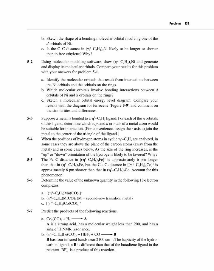
Problems 133
b. Sketch the shape of a bonding molecular orbital involving one of the d orbitals of Ni.
c. Is the C–C distance in (η2–C2H4)2Ni likely to be longer or shorter than in free ethylene? Why?
5-2 Using molecular modeling software, draw (η2–C2H4)2Ni and generate and display its molecular orbitals. Compare your results for this problem with your answers for problem 5-1.
a. Identify the molecular orbitals that result from interactions between the Ni orbitals and the orbitals on the rings.
b. Which molecular orbitals involve bonding interactions between d orbitals of Ni and π orbitals on the rings?
c. Sketch a molecular orbital energy level diagram. Compare your results with the diagram for ferrocene (Figure 5-9) and comment on the similarities and differences.
5-3 Suppose a metal is bonded to a η3–C3H3 ligand. For each of the π orbitals of this ligand, determine which s, p, and d orbitals of a metal atom would be suitable for interaction. (For convenience, assign the z axis to join the metal to the center of the triangle of the ligand.)
5-4 When the positions of hydrogen atoms in cyclic ηn–CnHn are analyzed, in some cases they are above the plane of the carbon atoms (away from the metal) and in some cases below. As the size of the ring increases, is the “up” or “down” orientation of the hydrogens likely to be favored? Why?
5-5 The Fe–C distance in [(η5–C5H5)2Fe]+ is approximately 6 pm longer than that in (η5–C5H5)2Fe, but the Co–C distance in [(η5–C5H5)2Co]+ is approximately 6 pm shorter than that in (η5–C5H5)2Co. Account for this phenomenon.
5-6 Determine the value of the unknown quantity in the following 18-electron complexes:
a. [(η6–C6H6)Mn(CO)2]z
b. (η6–C6H6)M(CO)3 (M = second-row transition metal)c. [(η6–C6H6)Co(CO)x]+
5-7 Predict the products of the following reactions.
a. Co2(CO)8 + H2 A A is a strong acid, has a molecular weight less than 200, and has a
single 1H NMR resonance.b. (η4–C4H6)Fe(CO)3 + HBF4 + CO B B has four infrared bands near 2100 cm–1. The hapticity of the hydro-
carbon ligand in B is different than that of the butadiene ligand in the reactant. BF4
– is a product of this reaction.

134 Chapter 5 Pi Ligands
c. Cr(CO)3(NCCH3)3 + cycloheptatriene C The number of infrared bands near 2000 cm–1 in the product is the
same as in the reactant.d. Cobaltocene + O2 D
The molecular weight of D is more than double that of cobaltocene. D has protons in four magnetic environments with relative NMR intensi-ties of 5:2:2:1. One half of D is a mirror image of the other half. D has an infrared band in the C–O single bond region.
5-8 Ferrocene reacts with the acylium ion, H3C–C≡O+, to give complex X, a cation; base extracts H+ from X to give Y, which has the formula C12H12FeO. Y reacts further with the acylium ion, followed by base, to give Z. Suggest structures for X, Y, and Z.
5-9 Heating [(η5–C5H5)Fe(CO)3]+ with NaH gives A, which has formula FeC7H6O2, plus colorless gas B. Molecule A reacts rapidly at room temperature to eliminate colorless gas C, forming solid D, which has empirical formula FeC7H5O2. Compound D has two strong IR bands, one near 1850 cm–1 and the other near 2000 cm–1. Treatment of D with iodine generates solid E of empirical formula FeC7H5O2I. Reaction of NaC5H5 with E yields solid F of formula FeC12H10O2. Upon heating, F gives off B, leaving a sublimable, orange solid G of formula FeC10H10. Propose structures for A through G.
5-10 Photolysis of (η5–C5H5)(η2–C2H4)2Rh in the presence of benzene in an unreacting solvent such as pentane yields a remarkable product having the following characteristics.
• It has the empirical formula RhC8H8.• It has a metal–metal bond and follows the 18-electron rule.• Although the 1H NMR spectrum has not been reported, it is likely to
have the following characteristics:• Three types resonances, with relative intensities 5:2:1• The largest peak should have a chemical shift similar to that of the
ring protons in the starting material. Finally, those who like to sail on the the sea might be particularly fond
of this molecule! Propose a structure for this product.31
5-11 The ring whizzer mechanism of rearrangement of (η4–C8H8)Ru(CO)3 is substantially slower than that for (η4–C8H8)Fe(CO)3 and can be observed by 1H NMR as well as 13C NMR. Suggest a reason for the slower rearrangement in the ruthenium compound.32
31J. Müller, P. E. Gaede, and K. Qiao, Angew. Chem. Int. Ed. Engl., 1993, 32, 1697.32F. A. Cotton and D. L. Hunter, J. Am. Chem. Soc., 1976, 98, 1413, and references therein.

Problems 135
5-12 Both the 1H and 13C variable temperature NMR spectra of (η4–C8H8)Fe(CO)3 have been reported. What information could be determined using 13C NMR that could not be determined using 1H NMR?33
5-13 Whereas the compound [(η5–C5H5)Fe(CO)]2 has bands in the infrared at 1904 and 1958 cm–1, [(η5–C5Me5)Fe(CO)]2 (Me = methyl) has bands at 1876 and 1929 cm–1.34
a. Account for the differences in position of these bands for the two compounds.
b. What does the appearance of two bands rather than a single band imply about the structures of these compounds?
5-14 (η5–C5H5)2Co(CO)3 has IR bands at 1965 and 1812 cm–1, but (η5–C5H5)2Co(CO)2 has only a single band, at 1792 cm–1. Account for this difference and provide sketches of both molecules that are consistent with the IR data and the 18-electron rule.
33F. A. Cotton, Acct. Chem. Res., 1968, 1, 257 and F. A. Cotton and D. L. Hunter, J. Am. Chem. Soc., 1976, 98, 1413.34M. Vitale, M. E. Archer, and B. E. Bursten, Chem. Commun. 1998, 179–180.

We have by no means exhausted the types of ligands encountered in organo-metallic chemistry. On the contrary, several additional classes of ligands are of immense importance. Three types of ligands containing metal–carbon σ bonds deserve particular attention: alkyl ligands; carbenes (containing metal–carbon double bonds), and carbynes (containing metal–carbon triple bonds). The latter two contain metal–carbon π interactions as well as σ interactions. In addition, several nonorganic ligands play important roles in organometallic chemistry. Examples include hydrogen atoms, dihydrogen (H2), phosphines (PR3), and the related arsenic and antimony compounds. In some cases these ligands exhibit behavior paralleling that of organic ligands; in other instances, their behavior is significantly different. In addition, complexes containing these ligands serve important functions in organometallic reactions, including catalytic processes.
6-1 COMPLEXES CONTAINING M–C, M=C,AND M��C BONDSComplexes containing direct metal–carbon single, double, and triple bonds have been studied extensively; the most important ligands having these types of bonds are summarized in Table 6-1.
6-1-1 Alkyl and Related ComplexesSome of the earliest known organometallic complexes were those having σ bonds between main group metal atoms and alkyl groups. Examples include
Other Important LigandsSIX
136

6-1 Complexes Containing M–C, M=C, and M��C Bonds 137
Table 6-1 Complexes Containing M–C, M=C, and M≡C Bonds
Ligand Formula Example
Alkyl —CR3
Carbene (alkylidene) =CRR′
Carbyne (alkylidyne) ≡CR
CrBr C
C
C
C
C
Ph
OO
OO
Grignard reagents, which have magnesium–alkyl bonds, and alkyl complexes with alkali metals, such as methyllithium. The syntheses and reactions of these main group compounds are typically discussed in detail in organic chemistry texts.
The first stable transition metal alkyls were synthesized in the first decade of the 20th century; many such complexes are now known. Examples of stable transition metal alkyls include Ti(CH3)4, W(CH3)6, and Cr[CH2Si(CH3)3]4. The metal– ligand bonding in these compounds may be viewed as primarily involving covalent sharing of electrons between the metal and the carbon in a σ fashion, as shown below.
M CR3 (R = H, alkyl, aryl)
sp3 orbital
In terms of electron counting, the alkyl ligand may be considered the two-electron donor, :CR3
– (method A), or the one-electron donor, .CR3 (method B). Significant ionic contribution to the bonding may occur in complexes of highly electroposi-tive elements such as the alkali metals and alkaline earths.
(CO)5Mn CH3
C(CO)5Cr
OCH3
Ph

138 Chapter 6 Other Important Ligands
Many synthetic routes to transition metal alkyl complexes have been developed. Four of the most important of these methods are as follows.
1. Reaction of transition metal halides with organolithium, organomagne-sium, or organoaluminum reagent.
Example: ZrCl4 + 4 PhCH2MgCl Zr(CH2Ph)4 + 4 MgCl2 6.1
2. Reaction of metal carbonyl anion with alkyl halide.
Example: Na[Mn(CO)5] + CH3I CH3Mn(CO)5 + NaI 6.2
3. Reaction of metal carbonyl anion with acyl halide. Example:
Fe O
CH3
CC
O
O
Fe
CH3CC
O
O
hνNa[(η5–Cp)Fe(CO)2]
+ CH3COCl
6.3
4. Reaction of metal halide with other non-transition metal alkyls.
Example: WF6 + 3 Zn(CH3)2 W(CH3)6 + 3 ZnF2 6.4
Although many complexes contain alkyl ligands, complexes containing alkyl groups as the only ligands1 are relatively few and have a tendency to be kineti-cally unstable and difficult to isolate;2 their stability is enhanced by structural crowding, which protects the coordination sites of the metal by blocking path-ways to decomposition. For example, the six-coordinate W(CH3)6 can be melted at 30 °C without decomposition, whereas the four-coordinate Ti(CH3)4 is subject to decomposition at approximately – 40 °C.3
1As previously mentioned, the term homoleptic has been coined to describe complexes in which all ligands are identical.2An interesting historical perspective on alkyl complexes is in G. Wilkinson, Science, 1974, 185, 109.3A. J. Shortland and G. Wilkinson, J. Chem. Soc., Dalton Trans., 1973, 872.
Exercise 6-1 Identify the transition metal in the following 18-electron complexes:a. CH3M(CO)4 M = First-row transition metalb. (η5-C5H5)CH3M(CO)2 M = First-row transition metalc. CH3M(CO)2(PMe3)2Br M = Third-row transition metal

6-1 Complexes Containing M–C, M=C, and M��C Bonds 139
Interestingly, homoleptic transition metal complexes of the methyl ligand and its derivatives tend to have geometries that are strikingly different from those of many other transition metal complexes. Re(CH3)6, for example, has trigonal prismatic geometry (Figure 6-1), and other six-coordinate methyl complexes, including W(CH3)6, have distorted trigonal prismatic geometry.4,5
In addition, alkyl complexes having β hydrogens tend to be much less stable (kinetically) than complexes lacking β hydrogens. Complexes with β hydrogens are subject to a method of decomposition called �-elimination, as illustrated in the following diagram.
CH2
CH2
H
LnM LnM
H
H2C
CH2
αβ
To provide stability, the β positions of alkyl ligands can be blocked in a variety of ways, for example:
C
CH3
CH3
CH3
CH2 CH2 CH2 CF3
β-Elimination reactions will be discussed in more detail in Chapter 8.Sometimes the kinetic instability of complexes containing β hydrogens can
be put to good use. As discussed in Chapter 9, the instability of alkyl complexes
4S. Kleinhenz, V. Pfennig, and K. Seppelt, Chem. Eur. J., 1998, 4, 1687.5For a discussion of the shapes of alkyl complexes related to the VSEPR model of molecular geometry, see G. S. McGrady and A. J. Downs, Coord. Chem. Rev., 2000, 197, 95.
Figure 6-1Structure of Re(CH3)6
Re
CH3
CH3
H3C CH3
CH3H3C
Re
CH3
H3C CH3
CH3H3C
CH3
Trigonal prismatic

140 Chapter 6 Other Important Ligands
having β hydrogens can be a useful feature in catalytic processes, where the rapid reactivity of an intermediate can be crucial to the effectiveness of the overall process. Many alkyl complexes, therefore, are important in catalytic cycles.
Several other ligands involve direct metal–carbon σ bonds. Examples are given in Table 6-2.
There are also many known examples of metallacycles, complexes contain-ing metals incorporated into rings.6 The following equation is an example of the synthesis of one metallacycle.
Pt
R3P
R3P+ 2 LiCl+
Li
Li
Metallacyclopentane
PtCl2(PR3)2
6.5
6B. Blom, H. Clayton, M. Kilkenny, and J. R. Moss, Adv. Organomet. Chem., 2006, 54, 149.
Table 6-2 Other Organic Ligands Forming σ Bonds to Metal
Ligand Formula Example
Aryl
Alkenyl (vinyl)
Alkynyl
H
H
Ta
C C
H H
H
Pt
PR3
Cl
PR3
C
H
CH2
C C Pt
PR3
Cl
PR3
C C

6-1 Complexes Containing M–C, M=C, and M��C Bonds 141
In addition to being interesting in their own right, metallacycles are proposed as intermediates in a variety of catalytic processes. More examples of metallacycles are provided in later chapters.
6-1-2 Carbene (Alkylidene) ComplexesCarbene complexes contain metal–carbon double bonds;7 they have the general structure shown below (X, Y = alkyl, aryl, H, or highly electronegative atoms such as O, N, S, or halogens). First synthesized in 1964 by Fischer and Maasböl,8 carbene complexes are now known for the majority of transition metals and for a wide range of ligands, including the prototype carbene :CH2.
C
X
Y
LnM
The original 1964 synthesis of a carbene complex was a classic in organome-tallic chemistry and generated the prototype of what are now known as Fischer carbene complexes. In this synthesis, W(CO)6 was allowed to react with phenyl-lithium in diethylether to form the anion [W(CO)5COC6H5]–. Reaction of this ion with diazomethane (CH2N2) yielded the carbene complex shown below in equation 6.6.
W(CO)6PhLiEt2O
(CO)5W C
O
Ph
Li+1) CH2N2 (CO)5W C
OCH3
Ph2) HOAc
+ LiOAc + N2
6.6
The chromium and molybdenum analogs to this tungsten carbene complex have subsequently been prepared.
The majority of carbene complexes, including those first synthesized by Fischer, contain one or two highly electronegative heteroatoms such as O, N, or S directly attached to the carbene carbon. These are commonly designated Fischer-type carbene complexes and have been studied extensively over the past four decades. Other carbene complexes contain only carbon and/or hydrogen attached to the carbene carbon. First synthesized several years after the initial Fischer
7IUPAC has recommended that the term “alkylidene” be used to describe all complexes containing metal–carbon double bonds and that “carbene” be restricted to free :CR2. For a detailed description of the distinction between these two terms (and between “carbyne” and “alkylidyne,” described later in this chapter), see W. A. Nugent and J. M. Mayer, Metal–Ligand Multiple Bonds, Wiley–Interscience: New York, 1988, pp. 11–16.8E. O. Fischer and A. Maasböl, Angew. Chem. Int. Ed. Engl., 1964, 3, 580.

142 Chapter 6 Other Important Ligands
carbenes, these have been studied extensively by Schrock’s research group as well as by many others; they are sometimes designated Schrock-type carbene complexes, commonly referred to as alkylidenes.9
Re
C
OC
C
C
O
OC
C
OO
OO
CH2
CH3
Ta
Fischer Carbene Complex Schrock Carbene (Alkylidene) Complex
In Chapter 6 we confine the discussion to a very qualitative view of the bond-ing in carbene complexes; more detail on the structure, bonding, and reaction chemistry of these complexes is discussed in Chapter 10.
The formal double bond in carbene complexes may be compared with the double bond in alkenes; in the case of the carbene complex, the metal must use a d orbital (rather than a p orbital) in forming the π bond with carbon, as illustrated in Figure 6-2.
Another important aspect of bonding in carbene complexes is that complexes having a highly electronegative “heteroatom” such as O, N, or S attached to the carbene carbon tend to be more stable than complexes lacking such an atom.
C
OCH3
Ph
(CO)5Cr C
H
Ph
(CO)5Cr
9R. R. Schrock, J. Am. Chem. Soc., 1974, 96, 6796; Acc. Chem. Res., 1979, 12, 98.
Figure 6-2 π Bonding in Carbene Complexes and in Alkenes
M C C C

6-1 Complexes Containing M–C, M=C, and M��C Bonds 143
For example, Cr(CO)5[C(OCH3)C6H5], with an oxygen on the carbene carbon, is much more stable than Cr(CO)5[C(H)C6H5]. The stability of the complex is enhanced if the highly electronegative atom can participate in the π bonding, with the result a delocalized, three-atom π system (analogous to the π–allyl system described in Chapter 2) involving a d orbital on the metal and p orbitals on carbon and on the heteroatom.10 An example of such a π system is illustrated in Figure 6-3. Such a delocalized three-atom system provides more stability than would a simple metal–carbon π bond. As discussed in Chapter 10, the presence of a highly electronegative atom can stabilize the complex by lowering the energy of the M−C−heteroatom bonding orbital.
The methoxycarbene complex Cr(CO)5[C(OCH3)C6H5], Figure 6–4, illustrates some important characteristics of bonding in transition metal carbene complexes.11 Evi dence for double bonding between chromium and carbon is provided by X-ray
10In some cases, d orbitals on the heteroatom can also participate.11E. O. Fischer, Adv. Organomet. Chem., 1976, 14, 1.
Figure 6-3 Delocalized π Bonding in Carbene Complexes. E Designates a Highly Electronegative Heteroatom such as O, N, or S.
M C
E
M C
E
M C
E
Antibonding
Nonbonding
Bonding

144 Chapter 6 Other Important Ligands
crystallography, which measures this distance at 204 pm, compared with a typical Cr–C single bond distance of approximately 220 pm.
One interesting aspect of this complex is its ability to exhibit a proton NMR spectrum that is temperature dependent. At room temperature a single resonance is found for the methyl protons; however, as the temperature is lowered, this peak first broadens and then splits into two peaks. How can this behavior be explained?
A single methyl proton resonance, corresponding to one magnetic environ-ment, is expected for the carbene complex as illustrated, with a double bond between chromium and carbon and a single bond (permitting rapid rotation about the bond) between carbon and oxygen. The room temperature NMR is therefore as expected, with a single methyl signal. The splitting of this peak at lower temperature into two peaks, however, suggests two different proton envi-ronments.12 Two environments are possible if there is hindered rotation about the C–O bond. A resonance structure for the complex can be drawn, showing some double bonding between carbon and oxygen; such double bonding is significant enough for cis and trans isomers, as illustrated in Figure 6-4, to be observable at low temperatures.
Evidence for double bond character in the C−O bond is also provided by crystal structure data, which exhibit a C–O bond distance of 133 pm, compared with a typical C–O single bond distance of 143 pm.13 The double bonding between carbon and oxygen, although weak (typical C=O bonds are much shorter, approx-imately 116 pm), is sufficient to slow down rotation about the bond so that at low temperatures proton NMR detects the cis and trans methyl protons separately. At higher temperature, there is sufficient energy to cause rapid rotation about the
12C. G. Kreiter and E. O. Fischer, Angew. Chem. Int. Ed. Engl., 1969, 8, 761.13O. S. Mills and A. D. Redhouse, J. Chem. Soc. A, 1968, 642.
Figure 6-4 Resonance Structures and cis and trans Isomers of Cr(CO)5[C(OCH3)C6H5]
(CO)5Cr C
OCH3
Ph
(CO)5Cr C
OCH3
Ph
–
+ (CO)5Cr C
Ph
O
H3C
(CO)5Cr C
Ph
O CH3
trans
cis

6-1 Complexes Containing M–C, M=C, and M��C Bonds 145
C–O bond so that the NMR sees only an average signal, which is observed as a single peak.
X-ray crystallographic data, as mentioned, show double bond character in both the Cr−C and C−O bonds. This supports the statement made early in the discussion of carbene complexes that π bonding in complexes of this type (con-taining a highly electronegative atom—in this case oxygen) may be considered delocalized over three atoms. Although not absolutely essential for all carbene complexes, the delocalization of π electron density over three or more atoms pro-vides an additional measure of stability to many of these compounds.14
6-1-3 Carbyne ComplexesNine years after Fischer’s report of the first stable transition metal–carbene complex, the first report was made of the synthesis of complexes containing a transition metal–carbon triple bond; fittingly this report was also made by the Fischer group.15 Carbyne complexes have metal–carbon triple bonds, and they are formally analogous to alkynes.16 Many carbyne complexes are now known; examples of carbyne ligands include the following.
M≡C−R R = aryl (first discovered), alkyl, H, SiMe3, NEt2, PMe3, SPh, and Cl
In Fischer’s original synthesis, carbyne complexes were obtained fortuitously as products of the reactions of carbene complexes with Lewis acids. For example, the methoxycarbene complex Cr(CO)5[C(OCH3)C6H5] reacts with the Lewis acids BX3 (X = Cl, Br, or I).
First, the Lewis acid attacks the oxygen, the basic site on the carbene.
C
OCH3
Ph
(CO)5Cr + BX3 [(CO)5Cr≡C–Ph]+X– + X2BOCH3
6.7
Subsequently, the intermediate loses CO, with the halogen coordinating in a position trans to the carbyne.
14Transition Metal Carbene Complexes, Verlag Chemie: Weinheim, Germany, 1983; pp 120–122.15E. O. Fischer, G. Kreis, C. G. Müller, G. Huttner, and H. Lorentz., Angew. Chem. Int. Ed. Engl., 1973, 12, 64.16Complexes containing metal–carbon triple bonds in which the metal is in a relatively high formal oxidation state are frequently designated alkylidynes. Carbyne complexes are also sometimes classified as Fischer-type or Schrock-type, as in the case of carbene complexes. The distinction between these is discussed in Chapter 10.

146 Chapter 6 Other Important Ligands
(CO)5Cr C−Ph + X2BOCH3 Cr C
C
CC
C
X Ph
OO
O O 6.8
The best evidence for the carbyne nature of the complex is provided by X-ray crystallography, which gives a Cr–C bond distance of 168 pm (for X = Cl), con-siderably shorter than the comparable distance for the parent carbene complex. The Cr≡C−C angle is, as expected, 180° for this complex; however, slight devia-tions from linearity are observed for many complexes in crystalline form—in part a consequence of the manner of packing in the crystal.
Bonding in carbyne complexes may be viewed as a combination of a σ bond plus two π bonds, as illustrated in Figure 6-5.
The carbyne ligand has a lone pair of electrons in an sp hybrid on carbon; this lone pair can donate to a suitable hybrid orbital on Cr to form a σ bond. In addition, the carbon has two p orbitals that can accept electron density from d orbitals on Cr to form π bonds. Thus, the overall function of the carbyne ligand is as both a σ donor and a π acceptor. For electron counting purposes a :CR+ ligand can be consid-ered a two-electron donor (an L ligand by method A); it is usually more convenient to count neutral CR as a three-electron donor (an LX ligand by method B).
Figure 6-5 Bonding in Carbyne Complexes
C R
C R
C R
M
M
M
Sigma:
Pi:

6-1 Complexes Containing M–C, M=C, and M��C Bonds 147
Carbyne complexes can be synthesized in a variety of ways in addition to Lewis acid attack on carbenes, as described previously. Synthetic routes for car-bynes and the reactions of these compounds have been reviewed in the literature.17 Reactions of carbynes will be discussed in more detail in Chapter 10.
In some cases molecules have been synthesized containing two or three of the types of ligands discussed in this section: alkyl, carbene, and carbyne. Such molecules provide an opportunity to make direct comparisons of lengths of metal–carbon single, double, and triple bonds, as shown in Figure 6-6.
17H. P. Kim and R. J. Angelici, “Transition Metal Complexes with Terminal Carbyne Ligands,” Adv. Organomet. Chem., 1987, 27, 51 and H. Fischer, P. Hoffmann, F. R. Kreissl, R. R. Schrock, U. Schubert, and K. Weiss, Carbyne Complexes, VCH Publishers: Weinheim, Germany, 1988.
Verify that Cr(CO)4Br(≡CPh) satisfies the 18-electron rule.
Method A Method BCr 6 electrons Cr 6 electrons4 CO 8 electrons 4 CO 8 electrons:Br– 2 electrons Br 1 electron:CC6H5
+ 2 electrons ≡CC6H5 3 electrons
18 electrons 18 electrons
Example 6-1
Identify the third-row transition metal in the following carbyne complexes.
a. (η5–C5Me5)M(CCMe3)(H)(PR3)2
b. M(C-o-tolyl)(CO)(PPh3)2Cl
Exercise 6-2
Figure 6-6 Complexes Containing Metal–Carbon Single, Double, and Triple Bonds
W
C
C
CMe3
P(CH3)2
CH3
CH2
(CH3)2P
H
Me3CTa
CH3H
H
W≡C: 178.5 pmW=C: 194.2 pmW−C: 225.8 pm
Ta=C: 202.6 pmTa−C: 224.6 pm
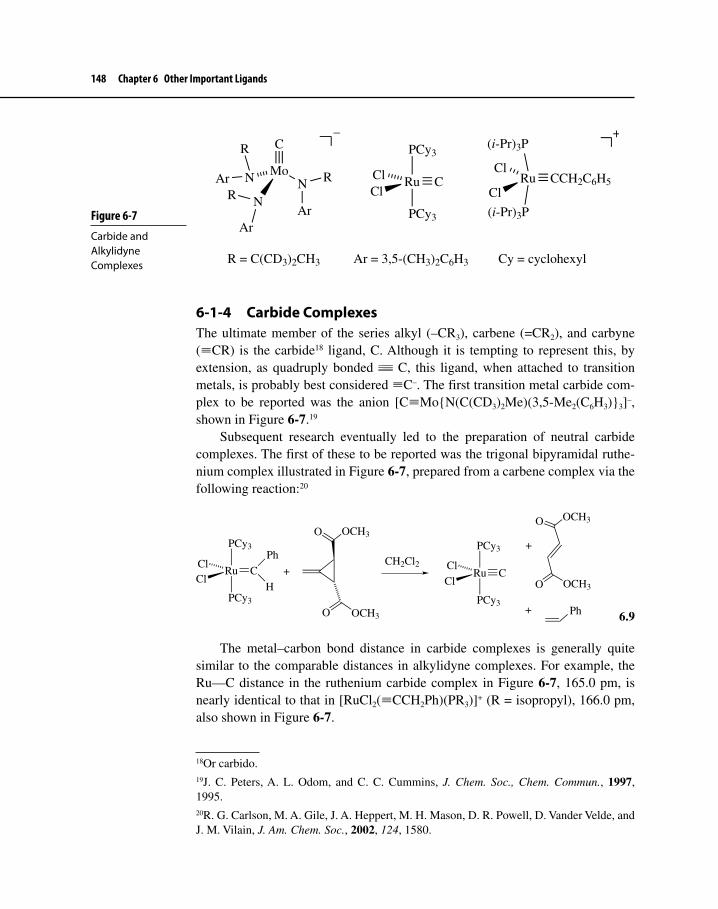
148 Chapter 6 Other Important Ligands
6-1-4 Carbide ComplexesThe ultimate member of the series alkyl (–CR3), carbene (=CR2), and carbyne (≡CR) is the carbide18 ligand, C. Although it is tempting to represent this, by extension, as quadruply bonded C, this ligand, when attached to transition metals, is probably best considered ≡C–. The first transition metal carbide com-plex to be reported was the anion [C≡Mo{N(C(CD3)2Me)(3,5-Me2(C6H3)}3]–, shown in Figure 6-7.19
Subsequent research eventually led to the preparation of neutral carbide complexes. The first of these to be reported was the trigonal bipyramidal ruthe-nium complex illustrated in Figure 6-7, prepared from a carbene complex via the following reaction:20
Ru
PCy3
C
PCy3
ClClRu
PCy3
PCy3
ClCl
C
Ph
H
O OCH3
O OCH3
CH2Cl2
O OCH3
O OCH3
Ph
+
+
+
6.9
The metal–carbon bond distance in carbide complexes is generally quite similar to the comparable distances in alkylidyne complexes. For example, the Ru—C distance in the ruthenium carbide complex in Figure 6-7, 165.0 pm, is nearly identical to that in [RuCl2(≡CCH2Ph)(PR3)]+ (R = isopropyl), 166.0 pm, also shown in Figure 6-7.
18Or carbido.19J. C. Peters, A. L. Odom, and C. C. Cummins, J. Chem. Soc., Chem. Commun., 1997, 1995.20R. G. Carlson, M. A. Gile, J. A. Heppert, M. H. Mason, D. R. Powell, D. Vander Velde, and J. M. Vilain, J. Am. Chem. Soc., 2002, 124, 1580.
Figure 6-7 Carbide and Alkylidyne Complexes
MoN
N
N
C
R
Ar
R
ArR
Ar
–
Ru
PCy3
C
PCy3
ClCl Ru
(i-Pr)3P
CCH2C6H5
(i-Pr)3P
Cl
Cl
+
R = C(CD3)2CH3 Ar = 3,5-(CH3)2C6H3 Cy = cyclohexyl

6-1 Complexes Containing M–C, M=C, and M��C Bonds 149
Carbide complexes themselves can act as σ donors, with this function carried through the carbon atom. In such circumstances the carbido carbon functions as a two-electron donor, for example:21
Ru
PCy3
PCy3
CCl
ClRu
PCy3
PCy3
CCl
ClMo
C
C
CO
C
C
OO
OO
(CO)5Mo(NMe3)
NMe3
6.10
One of the interesting characteristics of carbide complexes that can be useful in their characterization is their very large downfield 13C chemical shift, typically near 500 ppm.
Theoretical calculations on transition metal carbide complexes suggest that, as expected, both s and p components exist in the metal–C bonds and the π bond-ing component of the bonds is stronger than the σ bonding component.22
6-1-5 Other Organic LigandsThe list of ligands capable of bonding to metals through carbon is still in com-plete. Examples of several other important ligands not yet considered are given in Table 6-3.
Acyl complexes can be formed from migration of alkyl groups to CO ligands, as in the following example.
M
CH3
COM C
CH3
O
The formation of acyl complexes is an important step in carbonyl insertion reactions,23 as described in Chapter 8 (Section 8-1-1).
Trifluoromethyl, –CF3, and other perfluoroalkyl and perfluoroaryl complexes are, in general, much more thermally stable than their alkyl and aryl counterparts.
21A. Hejl, T. M. Trnka, M. W. Day, and R. H. Grubbs, J. Chem. Soc., Chem. Commun., 2002, 2524.22A. Krapp, K. K. Pandey, and G. Frenking, J. Am. Chem. Soc., 2007, 129, 7596.23As we will see, this name for this reaction is misleading!

150 Chapter 6 Other Important Ligands
For example, CF3Co(CO)4 can be distilled without decomposing at its boiling point, 91 °C, while CH3Co(CO)4 decomposes even at temperatures as low as –30 °C. The reasons for this enhanced stability in the perfluoro complexes are complex, but a major factor is clearly the greater bond dissociation energy of the M–ligand bond in the fluorine-containing ligands. In the perfluoroalkyl com-plexes, the highly electronegative fluorines cause the ligands to pull electrons away from the metal, inducing significant polarity into the M–C bond, a polarity that increases the bond strength. In the perfluoroaryl complexes, low-lying π* orbitals on the ligands are available to participate in back-bonding with the metal, likewise strengthening the M–C bond.
Table 6-3 Other Organic Ligands
Ligand Formula Example
Acyl
Perfluoroalkyl,perfluoroaryl
Vinylidene
Alkyne
C
O
R
Co
O
CH3
H3C
C
CC
C
O
O
OO
CF3 C6F5 Fe
F F
F
FFCCO
O
C CH2 Rh C C
H
PhR3P
C
C
R
R′
C
C
C(CH3)3
C(CH3)3
PtH3N
Cl
Cl

6-1 Complexes Containing M–C, M=C, and M��C Bonds 151
Vinylidene complexes are examples of carbene complexes having cumulated (consecutive) double bonds. Ligands with longer cumulated double bonds are called cumulenylidene ligands, and their complexes are called metallacumulenes. These ligands, with their long rod-like carbon chains, have been of considerable interest in recent years, partly because of possible applications as molecular wires and nonlinear optical materials in nano-devices.24,25 Metallacumulene complexes of general formula LnM(=C)mCR2 are well known for m = 1 (vinylidenes) and m = 2 (allenylidenes), but longer chains, especially for m = 3, have been more challenging. Examples having four and five carbon atoms in the chain have, however, been prepared. Selected examples of metallacumulene complexes are shown in Figure 6-8.
Many complexes containing alkyne ligands are known. Most commonly, these ligands act as two-electron donors, with a π orbital donating an electron pair in a manner analogous to a sidebound alkene. Bridging alkynes may be con-sidered to donate an electron pair to each of two metals (one pair from each of the alkyne’s two occupied π orbitals), acting as a two-electron donor to each. Alkyne complexes have been the subject of immense interest in the study of alkyne meth-athesis reactions, to be discussed in Chapter 11.26
24M. I. Bruce, Coord. Chem. Rev., 2004, 248, 1603.25K. Venkatesan, O. Blacque, and H. Berke, Organometallics, 2006, 25, 5190.26A. Fürstner and P. W. Davies, Chem. Commun., 2005, 2307.
Figure 6-8Metallacumulene Complexes
Mn C C C C
SnPh3
SnPh3PMe2P
CH3
Me2
Mn C C C C
PMe2PMe2
Me2P PMe2
Cl
+
C
Ph
Ph

152 Chapter 6 Other Important Ligands
6-2 HYDRIDE AND DIHYDROGEN COMPLEXES27,28
The simplest of all possible ligands is the hydrogen atom, H; similarly, the sim-plest possible diatomic ligand is the dihydrogen molecule, H2. It is perhaps not surprising that these ligands have gained attention, by virtue of their apparent simplicity, as models for bonding schemes in coordination compounds. Moreover, both ligands have played immense roles in the development of applications of organometallic chemistry to organic synthesis, especially catalytic processes. Although the hydrogen atom (ordinarily designated the hydride ligand) has been recognized as an important ligand for many years, the significance of the dihy-drogen ligand has become recognized relatively recently, and its chemistry is now developing rapidly.
6-2-1 Hydride ComplexesAlthough hydrogen atoms form bonds with nearly every element in the periodic table, we will specifically consider coordination compounds containing H atoms bonded to transition metals. Because the hydrogen atom has only a 1s orbital of suitable energy for bonding, the bond between H and a transition metal must, by necessity, be a σ interaction, involving metal s, p, and/or d orbitals (or a hybrid orbital). As a ligand, H may be considered a two-electron donor as hydride (:H–, method A) or a one-electron neutral donor (H atom, method B).
Although some homoleptic transition metal complexes of the hydride ligand are known—an example that is structurally interesting is the nine- coordinate [ReH9]2– ion29—we are principally interested in complexes containing H in combination with other ligands. Such complexes may be made in a variety of ways, as discussed in succeeding chapters. Probably the most common syn-thesis is by reaction of a transition metal complex with H2. The following are examples.
Co2(CO)8 + H2 2 HCo(CO)4 6.11
trans-Ir(CO)Cl(PEt3)2 + H2 Ir(CO)Cl(H)2(PEt3)2 6.12
The hydride ligand can often be readily recognized by 1H NMR because the H experiences strong shielding. Typical chemical shifts of hydrides are between ca. –2 and –12 ppm for terminal hydrides, with bridging hydrides absorbing at a still higher field.
27G. J. Kubas, Comments Inorg. Chem., 1988, 7, 17; R. H. Crabtree, Acc. Chem. Res., 1990, 23, 95; G. J. Kubas, Acc. Chem. Res., 1988, 21, 120.28J. K. Burdett, O. Eisenstein, and S. A. Jackson, “Transition Metal Dihydrogen Complexes: Theoretical Studies,” In Transition Metal Hydrides, A. Dedieu, Ed., VCH Publishers: New York, 1992.29S. C. Abrahams, A. P. Ginsberg, and K. Knox, Inorg. Chem., 1964, 3, 558.

6-2 Hydride and Dihydrogen Complexes 153
One of the most interesting aspects of transition metal hydride chemistry is the relationship between this ligand and the rapidly developing chemistry of the dihydrogen ligand, H2.
6-2-2 Dihydrogen ComplexesAlthough complexes containing H2 molecules coordinated to transition metals had been proposed for many years and many complexes containing hydride ligands had been prepared, the first structural characterization of a dihydrogen complex did not occur until 1984, when Kubas and co-workers synthesized the complexes M(CO)3(PR3)2(H2) (M = Mo, W; R = cyclohexyl, isopropyl).30 Subsequently, many H2 complexes have been identified, and the chemistry of this ligand has developed rapidly.
The bonding between dihydrogen and a transition metal can be described as shown in Figure 6-9. The σ electrons in H2 can be donated to a suitable empty orbital on the metal (such as a d orbital or a hybrid orbital), whereas the empty σ* orbital of the ligand can accept electron density from occupied d orbitals of the metal. The result is an overall weakening and lengthening of the H–H bond in comparison with free H2. Typical H–H distances in complexes containing coordinated dihydrogen are in the range 82–90 pm, in comparison with 74.14 pm in free H2.
This bonding scheme leads to interesting ramifications that are distinctive from other donor–acceptor ligands such as CO and cyclic π systems that are held together by multiple bonds. If the metal is electron rich and donates strongly to the σ* of H2, the H–H bond can rupture, giving separate H atoms as hydride ligands. Consequently, the search for stable H2 complexes has focused on metals likely to be relatively poor donors, such as those in high oxidation states or those surrounded by ligands that function as strong electron acceptors. In particular, good π acceptors such as CO and NO can be effective at stabilizing the dihydrogen ligand.
30G. J. Kubas, R. R. Ryan, B. I. Swanson, P. J. Vergamini, and H. J. Wasserman, J. Am. Chem. Soc., 1984, 106, 451.
Figure 6-9Bonding in Dihydrogen Complexes
M
H
HM
H
H
Sigma Donation Pi Acceptance

154 Chapter 6 Other Important Ligands
The dividing line between whether an M(H)2 or M(H2) structure will be favored is a narrow one, and subtle differences in environment can be important. For example, in {Rh[P(CH2CH2PPh2)3
](H2)}+, two isomers are found, as illus-trated below. If hydrogen occupies an apex of the trigonal bipyramidal isomer, it is present as H2; if hydrogen occupies cis positions of the octahedral isomer, it is present as separate H atoms.31 Calculations have demonstrated that there is less donation from the metal to the ligand at the apical site of the trigonal bipyramid than in the cis positions of the octahedral isomer.32
RhP
P
P
P
H H
Rh
P
P H
P
P H
+ +
Dihydrogen complexes have frequently been suggested as possible intermedi-ates in a variety of reactions of hydrogen at metal centers. Some of these reactions are steps in catalytic processes of significant commercial interest.
6-2-3 Agostic HydrogensIn some cases hydrogen atoms may form “bent” linkages between carbon atoms on ligands and metal atoms; such interactions have come to be described as agostic. Examples are illustrated in Figure 6-10.33 In the first structure, the Ti–C–C angle in the ethyl ligand is over 20° less than the regular tetrahedral angle for sp3 hybridized carbon. This has been interpreted as the consequence of a β hydrogen approaching the metal closely, forming a bridge between the β carbon and the metal.
Some such interactions have been substantiated by neutron diffraction; many others have been proposed, especially in reaction intermediates. The second
31C. Bianchini, C. Mealli, M. Peruzzini, and F. Zanobini, J. Am. Chem. Soc., 1987, 109, 5548.32F. Maseras, M. Duran, A. Lledos, and J. Bertran, Inorg. Chem., 1989, 28, 2984.33F. A. Cotton, Inorg. Chem., 2002, 41, 643 and M. Brookhart, M. L. H. Green, and G. Parkin, Proc. Nat. Acad. Sci., 2007, 104, 6908, and references cited therein.
Exercise 6-3 Explain why Mo(PMe3)5H2 is a dihydride (contains two separate H ligands), whereas Mo(CO)3(PR3)2(H2) contains the dihydrogen ligand (R = isopropyl).

6-3 Phosphines and Related Ligands 155
molecule in Figure 6-10 shows the first agostic interaction to be supported in this way.34 Because the hydrogen involved in an agostic interaction with a metal is, in effect, acting as a donor to form a weak bond with the metal, the C–H bond becomes elongated and the bond is weakened. The result is a tendency to “acti-vate” the C–H bond as a step toward further reaction. Several examples of these types of interactions are discussed in later chapters.
6-3 PHOSPHINES AND RELATED LIGANDSAmong the most important of all ligands are the phosphines, PR3.35 Together with other phosphorus-containing ligands and related compounds of arsenic and antimony, phosphines parallel the CO ligand in many ways. Like CO, phos-phines are σ donors (via a hybrid orbital containing a lone pair on phosphorus) and π acceptors. For many years it was thought that empty 3d orbitals of phos-phorus functioned as the acceptor orbitals, as shown in Figure 6-11. By this view, as the R groups attached to phosphorus become more electronegative, they withdraw electrons from phosphorus, making the phosphorus more positive and better able to accept electrons from the metal via a d orbital. The nature of the R groups, therefore, determines the relative donor/acceptor ability of the ligand. P(CH3)3, for example, is a strong σ donor by virtue of the electron-releasing
34R. K. Brown, J. M. Williams, A. J. Schultz, G. D. Stucky, S. D. Ittel, and R. L. Harlow, J. Am. Chem. Soc., 1980, 102, 981.35The IUPAC recommends that these compounds be called phosphanes, but the name phosphine is well established and commonly used.
Figure 6-10Examples of Agostic Interactions
Ti
Cl
Cl
P
P
Cl
H
Me2
Me2
229 pm
90.4˚86.3˚
Ru
PPh3
Cl PPh2
Ph3P Cl
H
Fe
PR3
R3P
R3P
H
R = OCH3
187 pm99.4˚
Figure 6-11 Bonding between Phosphines and Transition Metals (traditional view) Sigma Donation Pi Acceptance
M PR3M PR3

156 Chapter 6 Other Important Ligands
nature of the methyl groups; at the same time, it is a relatively weak π acceptor. PF3, on the other hand, is a strong π acceptor (and weak σ donor) and rivals CO in the overall strength of its interaction with metal d orbitals. Not surprisingly, complexes containing PF3 tend to obey the 18-electron rule. By changing the R groups, one can therefore “fine tune” the phosphine to be a donor/acceptor of a desired strength.
In 1985, a revised view of the bonding in phosphines was proposed.36 According to this proposal, the important acceptor orbital of the phosphine is not a pure 3d orbital, but rather a combination of a 3d orbital with a σ* orbital involved in the P−R bonding, as shown in Figure 6-12. This orbital has two acceptor lobes, similar to those of a 3d orbital, but is antibonding with respect to the P−R bond. To test this scheme, crystal structures of a variety of phosphine complexes in different oxidation states were compared. In most of these cases, as the charge on the metal became more negative, the P−R distance increased—as
36A. G. Orpen and N. G. Connelly, J. Chem. Soc., Chem. Commun., 1985, 1310.37 R. L. Harlow, R. J. McKinney, and J. F. Whitney, Organometallics, 1983, 2, 1839.
Figure 6-12Pi Acceptor Orbitals of Phosphines (revised view)
+
+
P P
PP
3d σ∗ Pπ Acceptor MOs
P
P
Exercise 6-4 The M–P distance in (η5–C5H5)Co(PEt3)2 is 221.8 pm and the P–C distance is 184.6 pm. The corresponding distances in [(η5–C5H5)Co(PEt3)2]+ are 223.0 pm and 182.9 pm.37 Account for the changes in these distances as the former complex is oxidized.

6-3 Phosphines and Related Ligands 157
Table 6-4 Selected Ligands of Phosphorus, Arsenic, and Antimony
Name Formula
Phosphine PR3
Phosphite P(OR)3
dppea (diphenylphosphinoethane)
diars
Ph2P PPh2
As(CH3)2
As(CH3)2
Arsine AsR3
Stibine SbR3
aThere are many similar ligands with four-letter acronyms to summarize their structures. For example: dmpe = dimethylphosphinoethane; depp = diethylphosphinopropane.
would be expected if additional electron density were pushed into an orbital having P−R antibonding character.
Similar interactions occur in other phosphorus-containing ligands and related ligands containing arsenic and antimony. Names and formulas of some of these ligands are given in Table 6-4.37
Steric ConsiderationsAn additional factor important in phosphine chemistry is the amount of space occupied by the R group. This factor is important in a variety of contexts; for example, the rate at which phosphine dissociates from a metal is related to the amount of space occupied by the phosphine and the resultant crowding around the metal. To describe the steric effects of phosphines and other ligands, Tolman has defined the cone angle as the apex angle θ of a cone that encompasses the van der Waals radii of the outermost atoms of a ligand, as shown in Figure 6-13.38 If the R group has substituents, these are folded back away from the metal. Values of cone angles of selected ligands are given in Table 6-5.39
38C. A. Tolman, J. Am. Chem. Soc. 1970, 92, 2953; Chem. Rev. 1977, 77, 313.39Values of cone angles have been revised on the basis of analysis of crystal structure information in the Cambridge Structural Database. For a review of these results and other

158 Chapter 6 Other Important Ligands
Figure 6-13Ligand Cone Angle M
P
θ
RR
R
228 pm
Table 6-5 Ligand Cone Angles
Ligand θ Ligand θ
PH3 87° P(CH3)(C6H5)2 136°PF3 104° P(CF3)3 137°P(OCH3)3 107° P(O-o-C6H4CH3)3 141P(OC2H5)3 109° P(C6H5)3 145°P(CH3)3 118° P(cyclo–C6H11)3 170°PCl3 124° P(t-C4H9)3 182°P(CH3)2(C6H5) 127° P(C6F5)3 184°PBr3 131° P(o-C6H4CH3)3 194°P(C2H5)3 132° P(mesityl)3 212°
As might be expected, the presence of bulky ligands can lead to more rapid ligand dissociation as a consequence of crowding around the metal. For example, the rate of the reaction
cis-Mo(CO)4L2 + CO Mo(CO)5L + L (L = phosphine or phosphite), 6.13
which is first order in cis-Mo(CO)4L2, increases with increasing ligand bulk, as shown by the cone angles in Table 6-6.40
Numerous other examples of the effect of ligand bulk on the dissociation of ligands have been reported in the chemical literature.41 We will see additional
considerations related to the steric effects of ligands on rates of substitution reactions, see K. A. Bunten, L. Chen, A. L. Fernandez, and A. J. Poë, Coord. Chem. Rev., 2002, 233–234, 41 and C. H. Suresh, Inorg. Chem., 2006, 45, 4982.40D. J. Darensbourg and A.H. Graves, Inorg. Chem., 1979, 18, 1257.41For example, M. J. Wovkulich and J. D. Atwood, Organometallics, 1982, 1, 1316 and J. D. Atwood, M. J. Wovkulich, and D. C. Sonnenberger, Acc. Chem. Res., 1983, 16, 350.

6-3 Phosphines and Related Ligands 159
examples of this effect as we examine reactions of organometallic complexes in later chapters.
Electronic EffectsIn addition to considering the steric bulk of phosphines and related ligands, Tolman developed a system for describing the electronic effects of such ligands. He based this system on the strong absorption band of A1 symmetry42 of com-plexes having the formula Ni(CO)3(PRR′R″), where the identity of the R, R′, and R″ groups had a strong influence on the position of this band.43 Considering a series of 70 ligands, Tolman chose P(t-Bu)3, the strongest donor ligand, as a refer-ence. Because the carbonyl ligands in Ni(CO)3[P(t-Bu)3] consequently exhibited the strongest back-bonding, the A1 absorption band of this complex occurred at the lowest energy, 2056.1 cm–1. Tolman defined a parameter χi to represent the effect of individual substituents (R, R′, R″) on this band:
νCO = 2056.1 cm–1 + ii=1
3
∑χ cm–1.
On the basis of spectra observed for complexes having particular ligands, a value of χi for each R substituent could then be determined. For example, the poorest donor ligand considered by Tolman was PF3. The A1 absorption band of Ni(CO)3(PF3) was at 2110.8 cm–1. Using this value for νCO in the equation above,
2110.8 cm–1 = 2056.1 cm–1 + ii=1
3
∑χ cm–1
54.7 cm–1 = ii=1
3
∑χ cm–1 = 3 × χi (for F) ; χi = 18.2 cm–1.
42This designates the totally symmetric vibration, in which all metal–ligand bonds stretch simultaneously.43C. A. Tolman, J. Am. Chem. Soc., 1970, 92, 2953.
Table 6-6 Rates of Reaction of cis-Mo(CO)4L2 a
Ligand Rate constant (×10–5s–1) Cone angle
P(OPh)3 < 1.0 128°PMePh2 1.3 136°P(O-o-tolyl)3 16 141°PPh3 320 145°PPh(cyclohexyl)2 6400 162°
aReactions were performed at 70 °C in CO-saturated tetrachloroethylene.

160 Chapter 6 Other Important Ligands
For phosphine ligands in which R, R′, and R″ are not identical, the values of χi for the individual R groups are summed to give the total effect on the A1 absorp-tion band.
Because the effect of different ligands on the position of the absorption band of the nickel complex is inherently related to the donor strength of the phospho-rus-containing ligand, a list of substituent groups R, R′, and R″ also shows the relative electron donating and accepting nature of these groups. Strongly donat-ing groups therefore have small values of χi (with the strongest donor, t-Bu, hav-ing χi = 0), and strongly electron withdrawing groups such as halogen atoms have large values. Representative values of χi are provided in Table 6-7.
31P NMRLike 1H and 13C, the 31P nucleus has a spin of ½. It is also the only stable isotope of phosphorus. Furthermore, the 31P chemical shift is highly sensitive to chemical structure and its chemical shift range is broad. As a consequence of these features, 31P NMR spectroscopy has had broad applications in the study of complexes of phosphines and other phosphorus-containing ligands. A recent review provides a variety of examples, including spectral analyses, of applications of 31P and 13C NMR to transition metal complexes with phosphorus-containing ligands.44
6-4 FULLERENE LIGANDSOne of the most fascinating developments in modern chemistry has been the syn-thesis of buckminsterfullerene, C60, and the related fullerenes (“buckyballs”) with their geodesic dome-like shapes. First reported as synthesized in the gas phase
44P. S. Pregosin, Coord. Chem. Rev., 2008, 252, 2156.
Table 6-7 Substituent χ Factors for Phosphine and Related Ligands
Substituent �i (cm–1) Substituent �i (cm–1)
–t-Bu 0.0 –OEt 6.8–Cyclohexyl 0.1 –OMe 7.7–i-Pr 1.0 –H 8.3–Et 1.8 –OPh 9.7–Me 2.6 –C6F5 11.2–Ph 4.3 –Cl 14.8–p-C6H4F 5.0 –F 18.2–m-C6H4F 6.0 –CF3 19.6

6-4 Fullerene Ligands 161
by Kroto, Smalley, and co-workers in 1985,45 C60, C70, and a variety of related species were soon synthesized; structures of C60 and C70 are shown in Figure 6-14. Subsequent work has been extensive, and many attempts have been made to coordinate fullerenes to metals.
6-4-1 Structures of FullerenesThe prototype fullerene, C60, consists of fused 5- and 6-membered carbon rings. Each 6-membered ring is surrounded, alternately, by hexagons and pentagons of carbons; each pentagon is fused to five hexagons. The consequence of this structural motif is that each hexagon is like the base of a bowl; the three penta-gons fused to this ring and linked by hexagons force the structure to curve (in contrast to graphite, in which each hexagon is fused to six surrounding hexagons in the same plane). This phenomenon, best seen by assembling a model, results in a dome-like structure that eventually curves around on itself to give a struc-ture resembling a sphere, the same shape as a soccer ball (which has an identi-cal arrangement of pentagons and hexagons on its surface).46 All 60 atoms are equivalent and give rise to a single 13C NMR resonance.
Although all atoms in C60 are equivalent, the bonds are not. Two types of bonds occur (best viewed using a model): at the fusion of two 6-membered rings and at the fusion of 5- and 6-membered rings. X-ray crystallographic studies on C60 complexes have indicated that the C–C bond length at the fusion of two 6-membered rings in these complexes is shorter, 135.5 pm, in comparison with the comparable distance at the fusion of 5- and 6-membered rings, 146.7 pm.47
45H. W. Kroto, J. R. Heath, S. C. O’Brien, R. F. Curl, and R. E. Smalley, Nature (London), 1985, 318, 162.46The structure of C60 has the same symmetry characteristics as an icosahedron.47S. Liu, Y. Lu, M. M. Kappes, and J. A. Ibers, Science, 1991, 254, 408.
Figure 6-14 C60 and C70
C60 C70

162 Chapter 6 Other Important Ligands
This is indicative of a greater degree of π bonding at the fusion of the 6-membered rings.
Surrounding each 6-membered ring with two pentagons (on opposite sides) and four hexagons (with each pentagon, as in C60, fused to five hexagons) yields a slightly larger, somewhat prolate structure with 70 carbon atoms. C70 is often obtained as a byproduct of the synthesis of C60 and is among the most stable of the fullerenes. Unlike C60, five different types of carbon are present in C70, giving rise to five 13C NMR resonances.48
6-4-2 Fullerene–Metal Complexes49
Although several types of compounds involving fullerenes and metals are known, we will focus on just one: complexes in which the fullerene itself behaves as a ligand. As a ligand, C60 appears to behave most commonly as an electron-defi-cient alkene (or arene) and to bond in a dihapto fashion. This type of bonding was observed in the first complex to be synthesized in which C60 acts as a ligand toward a metal, [(C6H5)3P]2Pt(η2–C60),50 illustrated in Figure 6-15.
A common route to the synthesis of fullerene complexes is by displacement of other ligands, typically those weakly coordinated to metals. Examples of such ligands include ethylene (equation 6.14) and CH3CN (equation 6.15).
[(C6H5)3P]2Pt(η2–C2H4) + C60 [(C6H5)3P]2Pt(η2–C60) (Figure 6–15) 6.14
3Cp*Ru(CH3CN)3+X– + C60 {[Cp*Ru(CH3CN)2]3C60}3+ + 3X–
(X– = O3SCF3–) 6.15
48R. Taylor, J. P. Hare, A. K. Abdul-Sada, and H. W. Kroto, J. Chem. Soc., Chem. Commun., 1990, 1423.49For a recent review of fullerene complexes, see A. Hirsch and M. Brettreich, Fullerenes, Wiley–VCH: Weinheim, Germany, 2005, pp. 231–250.50P. J. Fagan, J. C. Calabrese, and B. Malone, Science, 1991, 252, 1160.
Figure 6-15 Fullerene Complex of Platinum
PtPPh3
PPh3
Pt
PPh3
PPh3
41.3o
102.4o
or

6-4 Fullerene Ligands 163
Figure 6-16Bonding of C60 to Metal
MoFeC
C C
CO
O O
O
RhPh3P
C H
PPh3
O
Ti
M
The C60 ligand typically bonds to metals in a dihapto fashion, involving the carbon–carbon bond at the fusion of two 6-membered rings, as shown in Figure 6-16. Such a carbon–carbon bond is shorter, and thus has more π bonding charac-ter, than a bond at the fusion of 5- and 6-membered rings. Examples of complexes having this type of bonding mode are also shown in Figure 6-16.

164 Chapter 6 Other Important Ligands
Bonding of a fullerene to a metal leads to distortion at the site of attachment (also shown in Figure 6-16). This is similar to what happens when alkenes bond to metals: the four groups attached to the C=C bond of the alkene bend back away from the metal as d electron density from the metal is donated into the π* orbital of the alkene. Similarly, the d electron density of the metal can donate to an empty antibonding orbital of a fullerene and cause distortion. The effect is to pull the two carbons involved slightly away from the C60 surface. In addition, the distance between these carbons is elongated slightly as a consequence of this interaction. This increase in C–C bond distance is analogous to the elongation that occurs when ethylene and other alkenes bond to metals, as discussed in Chapter 5.
In some cases more than one metal can become attached to a fullerene sur-face. A spectacular example is [(Et3P)2Pt]6C60, illustrated in Figure 6-17.51 In this structure, the six (Et3P)2Pt units are arranged octahedrally around the C60. As usual, each platinum is bonded to two carbons at the juncture of two 6-membered rings; each of these pairs of carbons is pulled out slightly from the C60 surface.
Although complexes of C60 have been studied most extensively, some com-plexes of other fullerenes have also been prepared. An example is (η2–C70)Ir(CO)Cl(PPh3)2, shown in Figure 6-18.52 As in the case of the known C60 complexes, bonding to the metal occurs at the fusion of two 6-membered rings. The C70 ligand is prolate, elongated along the axis pointing toward the metal.
With its 5- and 6- membered rings, can C60 ever act as a pentahapto or hexa-hapto ligand? When Ru3(CO)12 and C60 are heated to reflux, the product shown in Figure 6-19 is formed, in which all three rutheniums are coordinated to a 6-membered ring of the fullerene. The C60 cannot satisfactorily be labeled as
51P. J. Fagan, J. C. Calabrese, and B. Malone, J. Am. Chem. Soc., 1991, 113, 9408.52A. L. Balch, V. J. Catalano, J. W. Lee, M. M. Olmstead, and S. R. Parkin, J. Am. Chem. Soc., 1991, 113, 8953.
Figure 6-17 [(Et3P)2Pt]6C60
(PPh3)2Pt
(Ph3P)2Pt Pt(PPh3)2
Pt(PPh3)2
(Ph3P)2Pt Pt(PPh3)2
: Denotes bond behind the C60 structure
C60center
Pt(PPh3)2
Pt(PPh3)2
Pt(PPh3)2
Pt(PPh3)2
(Ph3P)2Pt
(Ph3P)2Pt
Octahedral arrangementof η2–Pt(PPh3)2 groups
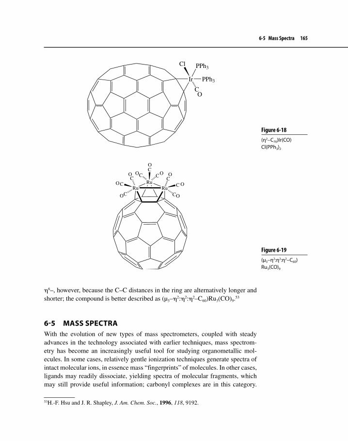
6-5 Mass Spectra 165
η6–, however, because the C–C distances in the ring are alternatively longer and shorter; the compound is better described as (µ3–η2:η2:η2–C60)Ru3(CO)9.53
6-5 MASS SPECTRAWith the evolution of new types of mass spectrometers, coupled with steady advances in the technology associated with earlier techniques, mass spectrom-etry has become an increasingly useful tool for studying organometallic mol-ecules. In some cases, relatively gentle ionization techniques generate spectra of intact molecular ions, in essence mass “fingerprints” of molecules. In other cases, ligands may readily dissociate, yielding spectra of molecular fragments, which may still provide useful information; carbonyl complexes are in this category.
53H.-F. Hsu and J. R. Shapley, J. Am. Chem. Soc., 1996, 118, 9192.
Figure 6-18(η2–C70)Ir(CO)Cl(PPh3)2
Ir
Cl
CO
PPh3
PPh3
Figure 6-19(µ3–η2:η2:η2–C60)Ru3(CO)9
RuRu
Ru
CCC
CC
C
CC
C
O
OOO
O
O
O
O
O

166 Chapter 6 Other Important Ligands
Table 6-8 Ionization Techniques in Mass Spectrometry
Type Ionization process Notes
Electron impact (EI) Collision of electron beam with molecule, causing ejection of electrons
“Hard” technique tends to cause fragmentation; samples must be vaporized
Fast atom bombardment (FAB)
Collision of beam of neutral atoms with solid sample
Less fragmentation than EI; spectra may include peaks from solid matrix
Atmospheric pressure ionization (API)
Continuous spray of sample solution at atmospheric pressure
Electrospray ionization (ESI)
High voltage yields aerosol of electrically charged droplets
Very soft technique, little fragmentation; useful for molecules of very high mass
Atmospheric pressure chemical ionization (APCI)
Plasma created by corona discharge causes gas phase ion– molecule reactions
Soft technique, little fragmentation
Matrix-assisted laser desorption ionization (MALDI)
UV laser pulse appliedto solid matrix containing sample
Soft technique, little fragmentation; used extensively for large biomolecules
In still other cases, structures may rearrange and/or fragment rapidly, yielding spectra that may be a true challenge to interpret. Sometimes compounds are not sufficiently volatile, do not ionize readily or decompose rapidly, or have other problems that result in their showing no mass spectra at all.
Our purpose is not to focus on the methods of mass spectrometry but rather to provide illustrations of some of the types of situations that may occur when this technique is used to characterize organometallic compounds. A brief but useful description of some of the techniques used in the mass spectrometry of coordina-tion compounds, including organometallic compounds, is available.54 Because mass spectrometry relies on the interaction of ions rather than neutral molecules with magnetic fields, the selection of ionizing techniques is an important consid-eration. Some of the most common ionizing techniques are listed in Table 6-8.
6-5-1 FragmentationMany organometallic complexes are subject to fragmentation during mass spec-trometry, especially if ionization occurs by a high-energy process such as electron impact. The most common type of fragmentation is the loss of one or more ligands.
54E. A. V. Ebsworth, D. W. H. Rankin, and S. Cradock, Structural Methods in Inorganic Chemistry, CRC Press: Boca Raton, FL, 1991, pp. 378–391.
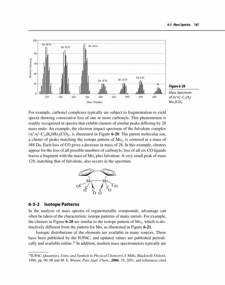
6-5 Mass Spectra 167
For example, carbonyl complexes typically are subject to fragmentation to yield specta showing consecutive loss of one or more carbonyls. This phenomenon is readily recognized in spectra that exhibit clusters of similar peaks differing by 28 mass units. An example, the electron impact spectrum of the fulvalene complex (η5:η5–C10H8)Mo2(CO)6, is illustrated in Figure 6-20. The parent molecular ion, a cluster of peaks matching the isotope pattern of Mo2, is centered at a mass of 488 Da. Each loss of CO gives a decrease in mass of 28. In this example, clusters appear for the loss of all possible numbers of carbonyls; loss of all six CO ligands leaves a fragment with the mass of Mo2 plus fulvalene. A very small peak of mass 128, matching that of fulvalene, also occurs in the spectrum.
Mo MoCC C
CCC
OO O
OOO
6-5-2 Isotope PatternsIn the analysis of mass spectra of organometallic compounds, advantage can often be taken of the characteristic isotope patterns of many metals. For example, the clusters in Figure 6-20 are similar to the isotope pattern of Mo2, which is dis-tinctively different from the pattern for Mo, as illustrated in Figure 6-21.
Isotopic distributions of the elements are available in many sources. These have been published by the IUPAC, and updated values are published periodi-cally and available online.55 In addition, modern mass spectrometers typically are
55IUPAC, Quantities, Units, and Symbols in Physical Chemistry, I. Mills, Blackwell: Oxford, 1988, pp. 90–98 and M. E. Wieser, Pure Appl. Chem., 2006, 78, 2051, and references cited
Figure 6-20 Mass Spectrum of (η5:η5–C10H8)Mo2(CO)6
320 400340 360 380 420 440 460 480
Mass Number
100
80
60
40
20
0
Rel
ativ
e In
tens
ity
M
M–COM–3CO
M–4COM–5COM–6CO
M–2CO

168 Chapter 6 Other Important Ligands
Mass Number Mass Number
RelativeAbundance
100
75
50
25
090 95 100 185 190 195 200
98 192
92
100
184
200
Mo Mo2
Figure 6-21Isotope Patterns of Mo and Mo2
equipped with software to calculate similated spectra based on distributions of isotopes. Mass spectra simulators are also available online.56
Many other ligands, especially those weakly bound and subject to dissocia-tion, can be lost during mass spectometry; examples include phosphines, N2, H2, and η2–C2H4. Cyclic π systems may also be lost, but often to a lesser extent; for example, the fulvalene ligand in Figure 6-20 remains attached to the metals, whereas the CO ligands are lost. In complexes containing both η5–Cp and CO ligands, the cyclopentadienyl ligands typically show a much stronger tendency to remain attached to transition metals than CO ligands.
Sometimes ligands themselves may fragment. For example, the electron impact spectrum of the dithiolate-bridged compound illustrated on the next page exhibits only a trace of a parent molecular ion cluster centered at m/z 534, but has an intense cluster at 478 corresponding to loss of ethylenes (mass of 28 each)
therein. Isotopic compositions of the elements and relative atomic masses of the isotopes can be found at http://physics.nist.gov/cgi-bin/Compositions/stand_alone.pl?ele=&ascii=html&isotope=some.56For example, http://www2.sisweb.com/mstools/isotope.htm.

6-5 Mass Spectra 169
from the diotholate bridges. There are no peaks corresponding to loss of the methylcyclopentadienyl ligands.
Mo
S
S S
SMo
CH3
CH3
6-5-3 Observing Molecular IonsComparatively “soft” ionization techniques such as electrospray and atmo-spheric pressure chemical ionization (APCI) may yield parent molecular ions with little or no fragmentation when other techniques fail. Clearly, such a tech-nique is the method of choice to determine the molecular mass in many situa-tions. An example of an APCI spectrum of a compound, [Cp(tfd)W(μ-S)2W(=O)Cp], shown below, that does not give a useful electron impact spectrum is shown in Figure 6-22.
W W
O
S
S
S
S
CF3
CF3
Figure 6-22APCI Spectrum of [Cp(tfd)W(μ-S)2W(=O)Cp] (Upper: Actual spectrum; lower: Calculated spectrum based on molecular formula and isotope distributions.)

170 Chapter 6 Other Important Ligands
Suggested Reading
Carbene (Alkylidene) ComplexesK. H. Dötz, H. Fischer, P. Hoffman, F. R. Kreissl, D. Schubert, and K. Weiss, Transition
Metal Carbene Complexes, Verlag Chemie: Weinheim, Germany, 1983.
Carbyne (Alkylidyne) ComplexesH. P. Kim and R. J. Angelici, “Transition Metal Complexes with Terminal Carbyne
Ligands,” Adv. Organomet. Chem., 1987, 27, 51.H. Fischer, P. Hoffman, F. R. Kreissl, R. R. Schrock, U. Schubert, and K. Weiss, Carbyne
Complexes, VCH: Weinheim, Germany, 1988.
MetallacyclesB. Blom, H. Clayton, M. Kilkenny, and J. R. Moss, “Metallacycloalkanes,” Adv.
Organomet. Chem., 2006, 54, 149.
Metallacumulenes and Other Molecules Containing Cn ChainsM. I. Bruce and P. J. Low, “Transition Metal Complexes Containing All-Carbon Ligands,”
Adv. Organomet. Chem., 2004, 50, 179.
Dihydrogen ComplexesG. J. Kubas, Proc. Natl. Acad. Sci. USA, 2007, 104, 6901.
Agostic InteractionsM. Brookhart, M. L. H. Green, and G. Parkin, Proc. Natl. Acad. Sci. USA, 2007, 104,
6908.W. Scherer, G. S. McGrady, Angew. Chem., Int. Ed., 2004, 43, 1782.
Phosphines and Cone AnglesK. A. Bunten, L. Chen, A. L. Fernandez, and A. J. Poë, Coord. Chem. Rev., 2002, 233–
234, 41.
31P NMRP. S. Pregosin, Coord. Chem. Rev., 2008, 252, 2156.
Fullerenes and Fullerene ComplexesA. Hirsch and M. Brettreich, Fullerenes, Wiley–VCH: Weinheim, Germany, 2005.
Mass SpectrometryE. Rosenberg, J. Chromatogr. A, 2003, 1000, 841.E. A. V. Ebsworth, D. W. H. Rankin, and S. Cradock, Structural Methods in Inorganic
Chemistry, CRC Press: Boca Raton, FL, 1991, pp. 378–391.

Problems 171
Problems6-1 Identify the first-row transition metal.
a. H3CM(CO)5
b. M(CO)(CS)(PF3)(PPh3)Brc. (CO)5M=C(OCH3)C6H5
d. (η5–C5H5)(CO)2M=C=C(CMe3)2
e. M(CO)5(COCH3)
6-2 Identify:
a. The third-row transition b. The second-row transition metal M: metal M′:
M
C
C
C
O
OC
Br
O
O
OO
M′
PPh3
PPh3
CCl
CO
6-3 Predict the transition metal-containing products of the following reactions.
a. [(η5–C5H5)W(CO)3]– + C2H5I b. Mn2(CO)10 + H2 c. Mo(CO)6 + PPh3 d. TaF5 + 5 LiCH3 A; A + LiCH3 B57
e. cis-Mo(CO)4(PPh3)2 + CO +
Would you predict that this reaction would be faster or slower if cis-Mo(CO)4(PMe2Ph)2 were used instead of cis-Mo(CO)4(PPh3)2?
Explain.6-4 Which complex would you predict to have the longer Fe–P bonds,
(η4–C4Ph4)Fe(CO)(PR3)2 or [(η4–C4Ph4)Fe(CO)(PR3)2]+, where R = OCH3? Explain.
6-5 Diphenylphosphinoethane (Table 6-4) reacts with W(CO)6 to yield a product having four infrared bands near 2000 cm–1. Provide a likely structure for this product.
6-6 Give likely structures for X and Y.
Fe(CO)5 + LiCH3 X
X + [(CH3)3O][BF4] Y
57S. Kleinhenz, V. Pfennig, and K. Seppelt, Chem. Eur. J., 1998, 4, 1687.

172 Chapter 6 Other Important Ligands
6-7 The complex Ir(CO)Cl(PEt3)2 reacts with H2 to give a product having two Ir–H stretching bands in the infrared and a single 31P NMR reso-nance. Suggest a structure for this product.
6-8 NaMn(CO)5 reacts with H2C=CHCH2Cl to give A + B. Compound A obeys the 18-electron rule and shows protons in three distinct mag-netic environments. Water-soluble compound B reacts with aqueous AgNO3 to form a white precipitate that turns gray on exposure to light. When heated, A gives off gas C and converts to D, which has protons in two distinct magnetic environments. Identify compounds A through D.
6-9 The complex [(η5–C5H5)Mo(CO)3]2 reacts with I2 to give a product A having three infrared bands near 2000 cm–1. This product reacts with triphenylphosphine to give B, which has two bands near 2000 cm–1. Identify A and B.
6-10 Reaction of [η5–C5(CH3)5]Ru(PR3)Br with H2 in toluene at 25°C yields a square pyramidal product with the η5–C5(CH3)5 ligand at the top of the pyramid. 1H NMR shows two peaks near δ = – 6 ppm but no evidence of H–H coupling or other indication of a bond between hydrogens [PR3 = P(isopropyl)2(C6H5)].
a. Propose a reasonable structure for the product.b. Suppose you wanted to prepare a dihydrogen complex using a similar
reaction. What type of phosphine would you use in your reactant and why?
6-11 For complexes having the formula trans-Rh(CO)ClL2 (L = phosphine), arrange the following phosphines in order of decreasing energy of the carbonyl stretching band in the IR for their corresonding complexes: PPh3, P(t-C4H9)3, P(p-C6H4F)3, P(p-C6H4Me)3, P(C6F5)3.
6-12 Equilibrium constants for the reaction Co(CO)Br2L2 CoBr2L2 + CO are given below. All values of K were measured at the same temperature.
L K PEt3 1 PEt2Ph 2.5 PEtPh2 24.2
a. Account for this trend in equilibrium constants.b. Of these three phosphines, which will give the cobalt complex with
the lowest energy carbonyl stretch in the infrared spectrum? Explain briefly.

Problems 173
6-13 Tolman’s cone angles for the phosphite ligands P(OMe)3, P(OEt)3, and P(OiPr)3 are, respectively, 107°, 109°, and 130°. However, examina-tion of crystal structures of complexes containing these ligands in the Cambridge Structure Database gave average angles, in the same order, of 124°, 125°, and 137°.58 Suggest why the Tolman angles may underes-timate the steric requirements of these ligands.
6-14 The compound [η5–C5Me5)Cr(CO)2]2 obeys the 18-electron rule. Exposure of this compound to ultraviolet light leads to the formation of X, which has the following characteristics.59
A single IR band at 1788 cm–1
A single 1H NMR resonance
a. What is the bond order between the Cr atoms?b. Propose a structure for X.
6-15 A Grignard reagent can be prepared from 1-bromobenzocyclobutene, shown below. When this Grignard reagent is allowed to react with Cp2Zr(CH3)Cl, the 16-electron complex 1 is formed. In the presence of P(CH3)3, 1 eliminates methane, forming 18-electron complex 2. Proton NMR of 2 shows resonances at δ 5.09 (relative area 5), 5.02 (5), 0.82 (9), multiple peaks at 6.31–6.78 (4), 3.40 (1), and 2.64–2.68 (1). The resonances at 5.09 and 5.02 are doublets, with the splitting attributable to P–H coupling. Elemental analysis of 2 indicated 63.12% carbon and 6.31% hydrogen. Propose structures for 1 and 2.60
Br
6-16 In a reaction that may have only one other example in the literature, the cation 1 reacts with the ion HB(sec-C4H9)3
– (a potential source of hydride) to form 2, a red–orange compound. The following data are reported for 2:61
58J. M. Smith and N. J. Coville, Organometallics, 2001, 20, 1210.59I. G. Virrels, T. F. Nolan, M. W. George, and J. J. Turner, Organometallics, 1997, 16, 5879.60T. V. V. Ramakrishna, S. Lushnikova, and P. R. Sharp, Organometallics, 2002, 21, 5685–5687.61I. Amor, D. García-Vivó, M. E. García, M. A. Ruiz, D. Sáez, H. Hamidov, and J. C. Jeffery, Organometallics, 2007, 26, 466.

174 Chapter 6 Other Important Ligands
Mo P Mo
t-Bu
t-Bu
t-Bu
CC
O
O
1
IR: strong bands at 1920, 1857 cm–1. 1H NMR: chemical shift (relative area):
5.46 (2) 5.28 (5) 5.15 (3) 4.22 (2) 0.7–2.0 (2) 1.31 (27)
13C NMR: resonance at 236.9 ppm, seven additional peaks and clusters of peaks between 32.4 and 115.7 ppm.
Propose (sketch) a structure for 2.
6-17 Reaction of Ir complex A with C60 yielded a black solid residue B with the following spectral characteristics: mass spectrum: M+ (m/z = 1056); 1H NMR: δ 7.65 (multiplet, 2H), 7.48 (multiplet, 2H), 6.89 (triplet, 1H, J = 2.7 Hz), and 5.97 ppm (doublet, 2H, J = 2.7 Hz); IR: vCO = 1998 cm–1.62
Ir CO
A
62R. S. Koefod, M. F. Hudgens, and J. R. Shapley, J. Am. Chem. Soc., 1991, 113, 8957.

Problems 175
a. Propose a structure for B.b. The carbonyl stretching frequency of A was reported as 1954 cm–1.
How does the electron density at Ir change in going from A to B? Explain.
c. When B was treated with PPh3, a new complex C rapidly formed along with some C60. What is the structure of C?
d. When B was treated with H2C=CH2, a new complex D formed along with C60. This time, however, the rate of formation of D was much slower than that for C. What is the structure of D? Why does it form much more slowly than C?

The diversity of the transition metals and also that of organic ligands indicates that the chemistry of organotransition metal complexes is indeed diverse, so much so that trying to understand the reactions of organotransition metal com-pounds would seem a daunting task. Over the past 40 years, much progress has been made in the study of organometallic reaction mechanisms. The good news from these investigations is that organometallic compounds undergo relatively few different kinds of reactions. Moreover, many of these reaction types have direct parallels with organic chemistry. We will try to point out these similarities during our discussion of basic kinds of reactions in this chapter and the next. Comprehension of these reaction types at this point in the text should greatly assist readers in grasping later topics in the textbook, such as catalysis and appli-cations of organometallic chemistry to organic synthesis.
In Chapter 7, we will consider reactions where the center of action occurs primarily at the metal and not the ligands. Reactions that occur mainly at the ligands will be discussed in Chapter 8.
Table 7-11 shows briefly several important kinds of organometallic reactions. Note that some of these reactions really are the same, although the forward reac-tion and the reverse reactions have different names (i.e., oxidative addition and
1A note on symbolism used throughout the remainder of the text is in order. Recall from Chapter 3 that the symbol L represents a ligand that donates two electrons to a complex (e.g., CO or phosphine). X (or sometimes Y or Z) represents a one-electron donor such as Cl or alkyl. To indicate a collection of unspecified L-type ligands (or sometimes L and X ligands) attached to a metal, the symbol Ln is used.
Organometallic Reactions IReactions That Occur at the Metal
SEVEN

Table 7-1 Common Reactions of Organotransition Metal Complexes
Reaction type Schematic example ∆ Oxidation state of M
∆ Coordination number of M
∆ e−
countText
section
Ligandsubstitution L'' + LnML' LnML'' + L' 0 0 0 7-1
Oxidativeaddition
LnM + X-Y LnM(X)(Y)
LnM(X)(Y) LnM + X−Y
+2 +2 +2 7-2
7-3−2
1,1-Insertiona
1,2-Insertiona
Y
LnM X Z LnM X
Z
Y1 1
Y
LnMZ
X 1LnM X Z
12Y
2
0 8-1-1
0 8-1-1
Nucleophilicadditionb
Nucleophilicabstractionb
Y
LnMZ
X+ Nuc:− 0c 0 0 8-2
LnM CR
O
+ Nuc−H LnM−H + Nuc CR
O
0 0 0 8-3
Electrophilicadditionb LnM−X=Z + E+ [LnM=X−Z−E]+
LnM−X−Z−Y + E+ LnM+
Z
X+ E-Y
0 0 0 8-4
8-4Electrophilicabstractionb
Reductiveelimination
0 0 0
π- and σ-Bondmetathesisd
C
C
R
R'
+C
C
R
R'
CC RR+
CC R'R'or
X
Y
W
Z+ or
X W
Y Z+
aThe reverse reaction, called deinsertion or elimination, is also possible.bThere is no one general reaction; several variations are possible.cDepends upon change in hapticity; e.g., X=Z going from η3 to η2 results in a 2 e− reduction.d∆ oxidation state, coordination number, and e− count are not applicable here, especially in π-bond metathesis where the metal complex is a catalyst.
11-1 and 11-4
[LnM−X−Z−Nuc]−
−2 −2
−2
−2
−1
−1

178 Chapter 7 Organometallic Reactions I
reductive elimination). Note also the change in electron count and oxidation state during the course of these reactions.2
7-1 LIGAND SUBSTITUTIONSometimes the first (and last) step in a catalytic cycle (to be discussed in Chapter 9), for example, ligand substitution is a common reaction type. This reaction is comparable in many ways to substitutions that occur at the carbon atom in organic chemistry. Equation 7.1 shows the general reaction.
LnML′ + L″ LnML″ + L′ 7.1
Much of the work on ligand substitution of organometallic complexes has involved metal carbonyls with a trialkyl or a triarylphosphine serving as the replacement ligand. Two main mechanistic pathways exist by which substitution may occur—associative (A) and dissociative (D).
Associative (A):
LnML' + L''slow
LnML'L''fast
LnML'' + L'
Dissociative (D):
LnML'slow
LnM+L'
fastLnML''
L''
The A pathway is characterized by a bimolecular rate-determining step involv-ing the substrate and incoming ligand (L″). Sixteen-electron complexes usually undergo ligand substitution by an A mechanism. D mechanisms, typically involv-ing 18-electron complexes, show a rate-limiting step in which one ligand on the substrate must depart before another can bind to the metal. Although there are clear-cut examples of dissociative and associative reactions, several ligand substi-tutions do not fit neatly into either type. The pathways of these reactions seem to lie between the mechanistic extremes of A and D. These mechanisms are called interchange (I) pathways, specifically labeled Ia (associative interchange) and Id (dissociative interchange), where, for example, Ia stands for interchange with an increase in coordination number in the rate-determining step. As in SN2 sub-stitution at carbon, I pathways go through no discrete, detectable intermediates.
2For a good discussion of a number of common types of organometallic reactions, see C. A. Tolman, Chem. Soc. Rev., 1972, 1, 337.

7-1 Ligand Substitution 179
The spectrum of pathways from D through I to A is analogous to the SN1–SN2 manifold found in organic chemistry.3
Another characteristic of ligand substitution reactions is the order of reac-tivity with respect to the metal in a triad such as Cr, Mo, W or Ni, Pd, Pt. The second-row transition metal complexes are usually more reactive than either of those containing first- or third-row elements. It is not completely clear why this trend exists, but certainly it must be a function of atomic covalent radius (for example, Cr < Mo ~ W; steric crowding among ligands decreases as one goes down the periodic table), nuclear charge (Cr < Mo < W; the incoming ligand is more attracted to the metal with higher nuclear charge), and M−L bond energy (bond dissociation energy for M—CO: Cr < Mo < W; the weaker the M−L bond, the more facile the substitution). The first two factors favor heavier atoms and the last favors the lightest atom in the triad. Considering these and possibly other grounds discussed later in Chapter 7, complexes containing the middle triad ele-ment are most reactive.
7-1-1 The trans Influence and trans EffectBefore we consider the mechanistic types of substitution reactions in more detail, it is worthwhile to consider a factor that can direct the course of ligand substi-tution known as the trans effect. It has long been known4 that, in square planar transition metal complexes especially, certain ligands seem to direct substitution preferentially to a position trans to themselves. Both thermodynamics and kinet-ics provide the basis for this tendency. When the reaction is controlled primarily by factors influencing the ground state energy of the complex, the trans effect is more correctly termed the trans influence.5 The kinetic trans effect is associated with reactions where factors affecting the transition state energy control the prod-uct outcome. Over the years, both phenomena have been lumped together as the trans effect. We will discuss in this section the two factors that govern the product distribution, dividing them into the trans influence and the kinetic trans effect.
Trans InfluenceLigands that form strong σ bonds, such as hydride and alkyl, or π acceptor ligands, such as CN–, CO, and PR3, which also bond strongly to the metal, tend
3D. T. Richens, Chem. Rev., 2005, 105, 1961. Although the review referenced here concerns ligand substitution in transition metal complexes that are more traditionally inorganic than organometallic in nature, it contains useful information on the mechanism of ligand substitu-tion that is relevant to organometallic chemistry.4I. I. Chernyaev, Ann. Inst. Platine, 1926, 4, 261.5Also called a structural trans effect. For a thorough discussion of the measurement and sig-nificance of the trans influence of ligands, see T. G. Appleton, H. C. Clark, and L. E. Manzer, Coord. Chem. Rev., 1973, 10, 335.

180 Chapter 7 Organometallic Reactions I
to weaken the metal–ligand bond trans to the first ligand. In the ground state, this is a thermodynamic property called the trans influence. Studies of square planar platinum complexes have demonstrated that a ligand does weaken the metal–ligand bond of the group situated trans to it.6 These investigations have indicated that a ligand with a strong trans influence causes, in the infrared region of the electromagnetic spectrum, a decrease in M−L stretching frequency of the ligand trans to it (thus indicating a weakening of the M−L bond).
Moreover, NMR studies have measured the coupling constant JPt–P of a num-ber of trialkylphosphine platinum complexes. Trialkyl phosphines, as shown in Figures 7-1a7 and b,8 have a greater trans influence than Cl, and this is reflected in the higher coupling constant (JPt–P) and lower IR Pt−Cl stretching frequency
6A. Pidcock, R. E. Richards, and L. M. Venanzi, J. Chem. Soc. A, 1966, 1707; L. M. Venanzi, Chem. Brit., 1968, 162; and F. Basolo, In Mechanisms of Inorganic Reactions, R. F. Gould, Ed., Advances in Chemistry Series, Vol. 49, American Chemical Society: Washington, D. C., 1965.7(a) Bond lengths (For PMe3 complex instead of PEt3) from X-ray data: G. G. Messner, E. L. Amma, and J. A. Ibers, Inorg. Chem., 1967, 6, 725; (b) IR stretching frequencies: P. L. Goggin and R. J. Goodfellow, J. Chem. Soc. A, 1966, 1462; NMR coupling constants (JPt–P): S. O. Grim, R. L. Keiter, and W. McFarlane, Inorg. Chem., 1967, 6, 1133.8(a) Bond lengths from X-ray data: G. G. Messner and E .L. Amma, Inorg. Chem., 1966, 5, 1775; (b) IR stretching frequencies: P. L. Goggin and R. J. Goodfellow, J. Chem. Soc. A,
Figure 7-1 Spectral and Structural Characteristics of Pt(II) Complexes
PtClEt3P
ClEt3P
238 pm
225 pm
ν (Pt-P) = 442 and 427 cm−1
ν (Pt-Cl) = 303 and 281 cm−1
J (Pt-P) = 3520 Hz
ν (Pt-P) = 415 cm−1
ν (Pt-Cl) = 341 cm−1
J (Pt-P) = 2400 Hz
PtPEt3Cl
ClEt3P229 pm
230 pm
PtClEt3P
CH3Et3P
a b
c
J (Pt-P, PEt3 trans to CH3) = 1719 HzJ (Pt-P, PEt3 trans to Cl) = 4179 Hz

7-1 Ligand Substitution 181
(vCl–Pt) present when Cl is trans to the phosphine rather than when PEt3 is trans to itself. The higher coupling constant in the cis isomer reflects the higher s char-acter of the ligand–metal bond. The methyl group (Figure 7-1c), on the other hand, has a higher trans influence than Cl, as reflected in the small JPt–P of 1719 Hz, when methyl is trans to the phosphine, and a JPt–P equal to 4179 Hz when phosphine is trans to Cl.9
Since the methyl group is a strong σ bonding ligand, it causes the σ bonding character of the Pt−P bond to decrease, thus decreasing the coupling constant. Phosphines in general have a high trans influence because they exert both strong σ donation and π acceptance from the metal, thereby weakening the bond trans to the phosphine.
Ligands that have a strong σ electron donating ability are listed10 in approxi-mate descending order of their effect.
H– > PR3 > SCN− > I−, CH3−, CO, CN− > Br− > Cl− > NH3 > OH−
Kinetic trans EffectThe tendency of certain ligands to direct incoming groups to the trans position also occurs with reactions under kinetic control. This case is known as the kinetic trans effect, whereby the influence of the ligand trans to the incoming one is felt due to the difference in energy between the ground state and the transition state in the rate-determining step. The σ donation effects are important, as well as the effect of π donation from the metal to the ligand. When a ligand forms strong π acceptor bonds with platinum, for instance, charge is removed from the metal. The effect on the energy of the ground state is relatively small, but it is significant on the transition-state energy because, during ligand substitution of a square planar Pt complex, we usually expect an increase in coordination to trigonal bipyramidal geometry in the transition state (see Section 7-1-2). A π bonding ligand originally present in the substrate (the complex undergoing substitution) can contribute to stabilizing the transition state, 1, via the dxz orbital from the metal.
X
Y
1
L
1966, 1462; NMR coupling constants (JPt–P): S. O. Grim, R. L. Keiter, and W. McFarlane, Inorg. Chem., 1967, 6, 1133. 9F. H. Allen and A. Pidcock, J. Chem. Soc. A, 1968, 2700.10F. R. Hartley, Chem. Soc. Rev., 1973, 163.

182 Chapter 7 Organometallic Reactions I
Overall, this effect increases the rate of reaction trans to the strong π acceptor ligand. The order of π bonding effects for various ligands is as follows.11
C2H4, CO > CN− > NO2− > SCN− > I− > Br− > Cl− > NH3 > OH−
When σ donation and π acceptance effects are combined, the overall trans effect list is as follows.12
CO, CN–, NO, C2H4, > PR3, H– > CH3–, S=C(NH2)2 > Ph–> NO2
–, SCN–, I–, > Br– > Cl– > Py, NH3, OH–, H2O
Ligands highest in the series are strong π acceptors, followed by strong σ donors. Ligands at the low end of the series possess neither strong σ nor π bond-ing abilities. The trans effect can be very large—rates in platinum complexes may differ as much as 104 between complexes with strong trans effect ligands and those with weak ones. Table 7-2 presents the relative rate of substitution of chloride(Cl) by pyridine (Py) on trans-Pt(PEt3)2(Cl)R when R is varied.13
To assess the nature of the trans effect, one must investigate the influence of a ligand in destabilizing the ground state (really the trans influence) and in stabilizing the transition state (the kinetic trans effect). Groups such as alkyl and hydride do not have π-acceptor orbitals and thus are unable to form π bonds to the metal that could effectively stabilize the trigonal bipyramidal transition state in an associative reaction involving a coordinatively unsaturated14 square planar com-plex. Presumably, these ligands are effective solely by lowering the bond energy of the M−X bond and destabilizing the reactant. Ligands such as CO and the phosphines can stabilize the trigonal bipyramidal transition state through π bond-ing and can also decrease the energy of the M−X bond in the ground state through
11See Footnote 10.12See Footnote 10.13F. Basolo, J. Chatt, H. B. Gray, R. G. Pearson, and B. L. Shaw, J. Chem. Soc., 1961, 2207.14A coordinatively unsaturated complex possesses less than 18 electrons and has sites avail-able for ligand bonding (e.g., a 16-electron square planar Pt complex). An octahedral, 18-electron complex, such as Cr(CO)6, is deemed coordinatively saturated.
Table 7-2 Effect of trans Ligand on Rate at 25 oC for the Reaction trans-Pt(Cl)(R)(PEt3)2 + Py → [trans- Pt(Py)(R)(PEt3)2]+ + Cl–
R k (M–1s–1)
H– 4.2CH3
– 6.7 × 10⁻²
Ph– 1.6 × 10⁻²
Cl– 4 × 10⁻⁴

7-1 Ligand Substitution 183
strong σ donation. It is sometimes difficult to determine the dominant effect, but Figure 7-2 summarizes the possible situations that could occur. When all is said and done, however, the phenomenon of selective labilization of ligands trans to other ligands is usually called the trans effect regardless of whether the reason for the effect of the directing ligand is kinetic or thermodynamic in origin.
The trans effect is somewhat different in octahedral complexes due to the smaller s character of each bond and possibly due to steric effects caused by the relatively greater crowding found in octahedral versus square planar environ-ments. In general, however, it appears that trans effects are related to the abil-ity of the ligand to stabilize the transition state during rate-limiting dissociation. Studies on octahedral Cr complexes15 indicate that the order of the trans effect is rather similar and follows the general trend as shown above.
Equations 7.2 and 7.3 provide two examples showing how one could perform a synthesis taking advantage of the trans effect. Equation 7.2 shows that Cl has a larger trans effect than NH3, but PEt3 has a larger trans effect than Cl according to equation 7.3.
NH3
Pt NH3H3N
NH3
Cl−
2+
NH3
Pt NH3Cl
NH3
+
Cl−NH3
Pt ClCl
NH3
7.2
15J. D. Atwood, M. J. Wovkulich, and D. C. Sonnenberger, Acc. Chem. Res., 1983, 16, 350 and B. J. Coe and S. J. Glenwright, Coord. Chem. Rev., 2000, 203, 5.
Figure 7-2Activation Energy and the trans EffectThe depth of the energy curve for the intermediate and the relative heights of the two maxima will vary with the specific reactants.
Ea
Ea
Ea
Higher energy ground state Lower energy transition state
Poor trans effect σ Bonding effect(trans influence)
π Bonding effect(kinetic trans effect)
E

184 Chapter 7 Organometallic Reactions I
PEt3
Pt PEt3Et3P
PEt3
Cl−
2+
PEt3
Pt PEt3Cl
PEt3
Cl−
+
Cl
Pt PEt3Cl
PEt3 7.3
7-1-2 Associative substitutionCoordinatively-unsaturated 16-electron complexes typically undergo associative substitution. Here the mechanism involves a slow bimolecular step where the incoming ligand and 16-electron complex combine to form a coordinatively satu-rated 18-electron intermediate. The intermediate rapidly expels the leaving group to give the new substituted 16-electron product. This is outlined in equation 7.4.
k1
k2 (fast)ML4 + Y ML4Y ML3Y + L 7.4
A two-term rate law lends support to the mechanism outlined above and often takes the following general form:
Rate = ks[ML4] + k1[ML4][Y].
The ks term arises because the solvent may also act as a nucleophile. Because a large excess of solvent is usually present in a reaction, the first term is called pseudo first order. The rate law expression is identical to that for an SN2 reaction in organic chemistry. These reactions typically have highly negative entropies of activation, which provides additional support for the associative nature of the reaction.16
16J. D. Atwood, Inorganic and Organometallic Reaction Mechanisms, 2nd ed., Brooks/Cole: Monterey, CA, 1997; pp. 55–66.
Exercise 7-1 Using the structure to the left of the reaction arrow as the starting material, propose a synthesis route to the structure on the right. You may use any reasonable reagents for your synthesis route.
a. PtI4
2− PtI
Py I
AsPh3
b. Cl
Rh
Cl
Rh
C
C
C
CRh
Cl
Ph3P C
PPh3(2 steps)
2
O
OO
OO

7-1 Ligand Substitution 185
Transition State Theory and Activation Volumes
The enthalpy of activation (ΔH‡) and the entropy of activation (ΔS‡), both derived from rate studies on reactions, are useful in providing information about the mechanism of a reac-tion. Both arise from transition-state theory (also known as absolute rate theory), which treats the activated complex at the transition state as a discrete entity in equilibrium with reactants. The value for ΔH‡ corresponds to Ea from the Arrhenius equation according to Ea = ΔH‡ + RT. Its magnitude is a measure of bond energy changes in going from reactants to the transition state. The entropy of activation indicates the change in order as the reac-tion proceeds to the transition state. A highly negative value for ΔS‡ implies that order increases on the way to the transition state, as exemplified by a bimolecular transforma-tion such as the Diels–Alder reaction. A reaction that gives a positive value for ΔS‡ indicates that the path to the transition state leads to greater disorder. Dissociative processes, such as the SN1 reaction, exhibit large positive values of ΔS‡.17
Another measure of the associative or dissociative nature of reactions is the activa-tion volume (∆V‡). The following equation shows the approximate relationship between the rate constant (kp or kobs) and the applied pressure.
ln kp ≈ ln ko − ∆V‡P/RT, where ko is the rate constant at zero pressure
Since measurable volume changes in solution require rather large changes in pressure, a special apparatus is required to measure ∆V‡. By plotting ln kobs vs. P, one can determine ∆V‡ from the slope. If kobs increases with increasing pressure (indicating that increasing pressure favors compaction of a transition state involving bond making), then the sign of ∆V‡ is negative. Dissociative reactions, on the other hand, resist increases in pressure. By increasing pressure, kobs should decrease because ∆V‡ is positive. Measurements of ∆V‡
have become increasingly common as a means of obtaining information about transition-state structure.18
Associative substitution is usually found with square planar d8 metal com-plexes such as those of Ni(II), Pd(II), Pt(II), Ir(I), and Au(III). Substitution reactions of these complexes have been thoroughly investigated.19 As in the
17For more information on absolute rate theory, see F. A. Carey and R. J. Sundberg, Advanced Organic Chemistry, Part A, 5th ed., Springer Science: New York, 2007, pp. 270–276.18See Footnote 3 and A. Drljaca, C. D. Hubbard, R. van Eldik, T. Asano, M. V. Basilevsky, and W. J. leNoble, Chem. Rev., 1998, 98, 2167.19A. Peloso, Coord. Chem. Rev., 1973, 10, 123; R. J. Cross, Chem. Soc. Rev., 1985, 14, 197; and J. P. Collman, L. S. Hegedus, J. R. Norton, and R. G. Finke, Principles and Applications of Organotransition Metal Chemistry, University Science Books: Mill Valley, CA, 1987, pp. 241–244, and references therein.

186 Chapter 7 Organometallic Reactions I
case of SN2 reactions, the rate of substitution depends upon several factors, including nucleophilicity (soft nucleophiles such as SCN– and PR3 are particu-larly effective when the metal center is soft [e.g., Pt(II)]), leaving group ability (a function of M−L bond strength or Brønsted–Lowry base strength; the weaker the base, the better the leaving group), the solvent,20 and the trans effect.
Hard and Soft Acids and Bases
The concept of hard and soft acids and bases needs some explanation here. We are really talking about the hardness or softness of Lewis acids or bases. Hard acids tend to be small in size, have a large positive charge, and possess an electron cloud that is not capable of significant distortion (non-polarizable). Examples of hard acids are H+, Al3+, or BF3. Soft acids are just the opposite, in that they tend to be of large size with respect to their charge and possess polarizable electron clouds. Species such as Hg2+, Tl+,.and low-valent transi-tion metals typify soft acids.
Hard and soft bases are similar to their acid counterparts except that they are electron rich species instead of electron poor. Hard bases would include F–, OH–, or NH3. Species such as I–, R2S, CO, or R3P constitute examples of soft bases. A good rule of thumb to apply when assessing the softness of an acid or base is to assume that softness increases as one proceeds down a column or group in the periodic table. Reactions between hard acids and hard bases readily occur because the two reacting partners have a strong coulombic attraction for each other. Soft acids and soft bases tend to react rapidly for a more subtle reason. Figure 7-3 indicates that soft acids and bases interact well because the HOMO (high-est occupied molecular orbital) of the base is close in energy to the LUMO (lowest unoccu-pied molecular orbital) of the acid, assuming that these orbitals have appropriate symmetry. Since the HOMO is filled with two electrons and the LUMO lacks electrons, the interaction between the two orbitals gives a doubly occupied bonding orbital and an empty antibond-ing orbital. Overall, the interaction of the two orbitals results in a significant energy lowering. This would not be the case if the acid were hard (the LUMO would be quite high in energy) and the base also hard (the HOMO is relatively low in energy). Then the HOMO and LUMO would be so far apart in energy that effective interaction between them would be negligible, resulting in very little energy lowering.
It is difficult to quantify the “hardness” or “softness” of a Lewis acid or base. We cannot measure a pKa value, as is the case when assessing the strength of Brønsted–Lowry acids.
20Solvents can have a profound effect on the rate of ligand substitution. For a recent article detailing the effect that ionic liquids (salts that are liquid at room temperature) can have on the rate of substitution, especially when the incoming ligand is anionic, see M. D. Singer, S. J. P’Pool, R. A. Taylor, J. McNeill III, S. H. Young, N.W. Hoffman, M. A. Klingshirn, R. D. Rogers, and K. H. Shaughnessy, J. Organomet. Chem., 2005, 690, 3540.

7-1 Ligand Substitution 187
R. G. Pearson has reported a scale of absolute hardness for acids and bases, defining hardness to be one-half the difference between the ionization potential and the electron affinity of an atom or species.21 He has obtained good agreement in many cases between the calculated values for hardness and the experimental behavior of the acid or base.
Unlike SN2 reactions in organic chemistry, associative substitution of square planar complexes usually results in retention of configuration and not inversion. Figure 7-4 indicates that the reaction is thought to proceed by attack of the incom-ing nucleophile Y (or solvent) from the top or up from the bottom to give a square–pyramidal intermediate that rearranges to a trigonal bipyramid. Note that the trans-directing ligand, Td, and the incoming and leaving ligands, Y and X, are all equatorial substituents of the trigonal bipyramid. Finally, the leaving group leaves and the final product is a square planar complex with the incoming ligand trans to Td. Equations 7.2 and 7.3 show typical associative ligand substitution reactions.22
21R. G. Pearson, Inorg. Chem. 1988, 27, 734. See also G. L. Miessler and D. A. Tarr, Inorganic Chemistry, 3rd ed., Prentice Hall: Upper Saddle River, NJ, 2004; pp. 183–192.22Not all square planar complexes of Pt undergo associative ligand substitution. Cis-(dimethyl)(dimethylsulfoxide)(triarylphosphine)platinum(II) undergoes displacement of DMSO by pyri-dine via dissociation of DMSO in the rate-determining first step. Retention of configuration is observed, presumably via a T-shaped intermediate. See R. Romeo, L. M. Scolaro, M. R. Plutino, F. F. de Biani, G. Bottari, and A. Romeo, Inorg. Chim. Acta., 2003, 350, 143.
Figure 7-3 HOMO–LUMO Interactions of Hard and Soft Acids and Bases
LUMO(Acid)
HOMO(Base)
LUMO(Acid)
HOMO(Base)
Soft-Soft Hard-Hard
∆E
∆E
E

188 Chapter 7 Organometallic Reactions I
Associative Substitution with 18-Electron SystemsThe 18-electron rule makes it unlikely that coordinatively-saturated, 18-electron complexes would undergo substitution by an A mechanism. An exception to this conventional wisdom was formulated by Basolo,23 who postulated that substitu-tion in 18-electron complexes may occur associatively if the metal complex can delocalize a pair of electrons onto one of its ligands.
For example, equation 7.5 shows substitution of an 18-electron molybdenum complex by phosphine ligand,24 which proceeds with a rate law first order in starting complex and first order in incoming ligand—exactly as would be dem-onstrated in an associative substitution of a 16-electron square planar complex as discussed earlier in Section 7-1-2. Note that the rate-determining step of this reaction involves a change in hapticity of the arene ligand from η6 to η4, coinci-dent with attachment of the incoming phosphine ligand.
MoMoC C
C
PPh3
Slow PPh3
CC
CPPh3 PPh3
MoC
C PPh3
PPh3
PPh3
C
+ PhH
O
O
O
O
O
O
O
OO
7.5
23F. Basolo, Inorg. Chim. Acta, 1981, 50, 65.24F. Zingales, A. Chiesa, and F. Basolo, J. Am. Chem. Soc., 1966, 88, 2707.
Figure 7-4 Ligand Substitution of a Square Planar Complex
M
LTd
XL
Y+ M
LTd
XL
Y
M
LTd
X
L
Y
M
LTd
YL
X+
Square planar Square pyramid
Trigonal bipyramidSquare planar

7-1 Ligand Substitution 189
Such a change preserves the electron count in the coordination sphere when the extra incoming ligand is attached. Studies on similar molybdenum–triene complexes have resulted in the isolation of 18-electron η4–(triene)Mo(CO)3(PR3); moreover, an η4–arene complex has been isolated and characterized in the solid state.25
Equations 7.6–7.9 provide examples of associative substitution reactions on 18-electron complexes. In all cases, modification of the electron contribu-tion of one of the ligands occurs. In reaction 7.6 the nitrosyl group rearranges from its 3- electron, linear form (an 18 e– complex) to a 1-electron, bent form (a 16-e– complex).26 This allows the phosphine to attack to give the 18 e– complex Co(CO)3(PR3)(NO). Finally, CO departs to give the product. The overall rate of the reaction is related to the nucleophilicity of the phosphine and follows the order PEt2Ph ~ PPh3 > P(OPh)3 (see Section 6–3).
Co(CO)3NO + PR3 Co(CO)2(PR3)(NO) + CO 7.6
Reaction 7.7 involves conversion from η5 to η1–Cp (via η3),27 and reaction 7.8 shows “slippage” of η5 to η3–indenyl. Such slippage is quite rapid compared with the η6 to η4 change observed with comparable metal complexes of η6–benzene or the η5 to η3 transformation when η5–Cp is the π ligand. This “indenyl ligand effect” was noted by Basolo, who attributed the enhanced reactivity to the greater resonance stabilization of the η3–indenyl group (with one aromatic ring intact) compared with η4–benzene or η3–Cp, which are no longer aromatic.28 One of the most interesting examples of this type involves reorganization of electrons in a tetrazole ligand attached to iron, shown in equation 7.9. The tetrazole changes from ligand-type L2 to X2 and finally back to L2. The ∆H‡ of 6.9 kcal/mol and ∆S‡ of −31.4 eu clearly support a rapid associative mechanism for the reaction.29
ReNC
Me
+ 2 PMe3 ReMe3P
C Me
PMe3
N
O
O
O
O
7.7
25D. J. Darensbourg, “Ligand Substitution in Metal Carbonyls,” In F. G. A. Stone and R. West, Eds., Advances in Organometallic Chemistry, Academic Press: New York, 1982, Vol. 21, p. 123.26J. S. Howell and P. M. Burkinshaw, Chem. Rev., 1983, 83, 557.27C. P. Casey and J. M. O’Connor, Organometallics, 1985, 4, 384 and C. P. Casey, J. M. O’Connor, and K. J. Haller, J. Am. Chem. Soc., 1985, 107, 1241.28M. E. Rerek, L. N. Ji, and F. Basolo, J. Chem. Soc., Chem. Commun., 1983, 1208 and L. N. Ji, M. E. Rerek, and F. Basolo, Organometallics, 1984, 2, 740.29C. Y. Chang, C. E. Johnson, T. G. Richmond, Y. T. Chen, W. C. Trogler, and F. Basolo, Inorg. Chem., 1981, 20, 3167 and Q. Z. Shi, T. G. Richmond, W. C. Trogler, and F. Basolo, Organometallics, 1982, 1, 1033.

190 Chapter 7 Organometallic Reactions I
RhC C
PPh3
SlowRh
C C
PPh3
RhC PPh3
Fast+ CO
η5–indenyl
O O O O O
7.8
NN
(CO)3Fe
NN
Me
Me
NN
(PMe3)(CO)2Fe
NN
Me
Me
NN
(Me3P)(CO)3Fe
NN
Me
Me
PMe3+ CO
7.9
7-1-3 Dissociative DisplacementsThe D mechanism requires the formation of an intermediate with reduced coor-dination number, and it is the most common pathway for 18-electron complexes, as outlined in equations 7.10 and 7.11.
k1ML6 ML5 + L 7.10 k–1
k2ML5 + Y ML5Y 7.11
Application of the steady state approximation30 produces a rate law for this mechanism as
30The steady-state approximation assumes that, in a multistep reaction, the concentration of intermediates is small and constant because the rate of their formation equals their rate of destruction. Application of the steady-state approximation for equations 7.10 and 7.11 proceeds as follows:
We first write the rate law as
Rate = k2[ML5][Y].
Since we do not know the concentration of the fleeting intermediate, ML5, we apply the steady-state approximation to find its concentration in terms of variables that are measurable. We assume that the change in concentration of ML5 with time is equal to zero (that is, the rate of
Exercise 7-2 a. Propose a structure for the starting material in equation 7.6.b. Calculate the electron count for each complex in equation 7.9.

7-1 Ligand Substitution 191
k1k2[ML6][Y]
Rate = ——————.
k–1[L] + k2[Y]
If the concentration of leaving group (L) is relatively small compared with that of the incoming nucleophile or if k–1 is small, then the rate law reduces to
Rate = k[ML6],
which is much like the rate law for a limiting SN1 reaction in organic chemis-try. Studies have shown, however, that the resulting 16-electron intermediates, formed upon ligand dissociation, are highly reactive and show little selectivity toward achieving coordinative saturation. Thus, k–1 is often comparable in magni-tude to k2,31 and the more complicated rate law holds unless the incoming ligand is in large concentration. Studies on the kinetics of ligand substitution reactions of metal carbonyl complexes have yielded significant information on the mech-anism of displacement of other neutral ligands (e.g., phosphines, alkenes, and amines) from low-valent metal centers. A typical example of a substitution that occurs by a D mechanism is shown in equation 7.12.32
Cr(CO)6 + PPh3 Cr(CO)5PPh3 + CO 7.12 130 oC
formation of intermediate is equal to the rate of disappearance; this is the approximation). Thus,
d[ML5]/dt = 0 = k1[ML6] − k–1[ML5][L] − k2[ML5][Y].
Rearranging terms in order to solve for [ML5], we have
[ML5]{k–1[L] + k2[Y]} = k1[ML6]
and
[ML5] = k1[ML6]/{k1[L] + k2[Y]}.
Plugging the value for [ML5] back into the original rate law expression, we have a new equation:
Rate = k1k2[ML6][Y]/{k–1[L] + k2[Y]}.
For more discussion of the steady-state approximation, see I. N. Levine, Physical Chemistry, 3rd ed., McGraw–Hill: New York, 1988, pp. 532–533; and F. A. Carey and R. J. Sundberg, Advanced Organic Chemistry, Part A, 5th ed., Springer Science: New York, 2007, pp. 282–283.31D. J. Darensbourg, “Ligand Substitution in Metal Carbonyls,” In F. G. A. Stone and R. West, Eds., Advances in Organometallic Chemistry, Academic Press: New York, 1982, Vol. 21, p. 115.32J. A. S. Howell and P.M. Burkinshaw, Chem. Rev., 1983, 83, 559, and references therein.

192 Chapter 7 Organometallic Reactions I
Relative RatesRates of substitution for various ML6 complexes (the carbonyl complexes have been the most studied) differ considerably depending on the metal and the ligands present. The 18-electron species [V(CO)6]– is resistant to substitution by even molten PPh3.33 Group 6 hexacoordinate complexes typically show k1 values rang-ing from 10–12 to 10–3 sec–1.34
As mentioned in Section 7-1, second-row complexes tend to react faster than first- or third-row complexes in simple ligand substitutions that occur by a dis-sociative mechanism.35 This trend has been well studied for Group 6 complexes and is often observed with d9 and d10 metals. For the series of metal carbonyls M(CO)6 where M = Cr, Mo, and W, the observed order of reactivity does not mirror the order of M−C bond energies, which are W > Mo > Cr. The order does seem to correspond to the calculated values for the force constants of M−C bonds in Group 6 metal carbonyls.36
Steric EffectsSteric effects play a role in the rate of ligand displacement. The rate of reaction for equation 7.13 has been measured for a number of phosphine ligands (PR3), and the results indicate that the rate of substitution is accelerated by bulky phos-phines. A good correlation between cone angle (see Section 6–3) of the phos-phine (or phosphite) ligand and rate of displacement by CO was obtained, as shown in Table 7-3.37
cis-Mo(CO)4(PR3)2 + CO Mo(CO)5(PR3) + PR3 7.13
The cis EffectOctahedral complexes of the general formula M(CO)5X often exhibit a tendency to lose a CO substituted cis to the X ligand (Group 6 and 7 metal complexes have
33A. Davidson and J. E. Ellis, J. Organomet. Chem., 1971, 31, 239.34D. J. Darensbourg, “Ligand Substitution in Metal Carbonyls,” In F. G. A. Stone and R. West, Eds., Advances in Organometallic Chemistry, Academic Press: New York, 1982, Vol. 21, p. 117.35D. J. Darensbourg, “Ligand Substitution in Metal Carbonyls,” In F. G. A. Stone and R. West, Eds., Advances in Organometallic Chemistry, Academic Press: New York, 1982, Vol. 21, p. 116.36Force constants (k) of bonds directly relate to the IR stretching frequency: the higher the value for k, the higher the value for the stretching frequency. See J. A. S. Howell and P. M. Burkinshaw, Chem. Rev., 1983, 83, 559, and references therein.

7-1 Ligand Substitution 193
been well investigated).38 This phenomenon of cis labilization is termed the cis effect.39 Loss of a carbonyl group from an octahedral complex provides two dis-tinct square pyramidal intermediates, a and b (Figure 7-5), depending on whether the CO is lost from a position cis (a) or trans (b) to X.
37D. J. Darensbourg, “Ligand Substitution in Metal Carbonyls,” In F. G. A. Stone and R. West, Eds., Advances in Organometallic Chemistry, Academic Press: New York, 1982, Vol. 21, p. 119.38J. D. Atwood and T. L. Brown, J. Am. Chem. Soc., 1976, 98, 3160.39Cis effects occur with square planar Pt complexes, but these are very small and the order of the effect with respect to ligand is variable. For a discussion, see J. D. Atwood, Inorganic and Organometallic Reaction Mechanisms, 2nd ed., VCH: New York, 1997, pp. 51–52.
Table 7-337 Rates of Ligand (L) Replacement by CO at 70 oC
L Cone angle (o) Rate constant (sec–1) ΔH‡ (kcal/mol) ΔS‡ (eu)a
Phosphines PMe2Ph 122 <1.0 x 10⁻⁶
PMePh2 136 1.33 x 10⁻⁵
PPh3 145 3.16 x 10⁻³ 29.7 14.4 PPhCy2
b 162 6.40 x 10⁻² 30.2 21.7Phosphites P(OPh)3 128 <1.0 x 10⁻⁵
P(O-o-tol)3c 141 1.60 x 10⁻⁴ 31.9 14.4
aeu = cal/mol-K.bCy = cyclohexyl.co-tol = ortho-toluyl (o-methylphenyl).
Figure 7-5 Intermediates in the Substitution of M(CO)5X Complexes
MC
C C
X
C
C
− CO
− CO
MC
C C
X
C+ Y M
C
C C
X
C
Y
MC
C
X
C
+ Y
a
b
a
b
O
CO
MC
C
X
CO
CO
Y
O
O
O O
M = Group 6 metal (m = −1)M = Group 7 metal (m = 0)
m
m m
mmO
O
O
O
O
O
O O
O
OO
O
O

194 Chapter 7 Organometallic Reactions I
Calculations show40 that a ligand such as a halogen (a poor σ donor and π acceptor) stabilizes the geometry shown in a more than b and thus as a conse-quence of the Hammond postulate (see below), the transition state leading to a is more stable than that leading to b. When cis ligands are present that do not share the electronic properties of the halogens (i. e., they are better σ donors and/or have the capacity for π acceptance), the preference for cis labilization is reduced. Ligands that are stronger π acceptors than CO (such as F2C=CF2) actually labilize preferential loss of the trans CO.
The Hammond Postulate
A mechanism is a description of events—primarily bond breaking and making—that occur during the transformation of reactant to product. It is important to have knowledge about the structure of transition states, especially the one involved in the rate-determining step. Such knowledge assists the chemist in predicting what effects different substituents will have on the rate of the reaction and the product distribution (if more than one product is possible) and in understanding the role of stereochemistry on the transformation of reactant to product.
Careful application of the Hammond postulate allows us to ascertain the structure of the transition state under certain conditions if we know something about the structure and energy of the next prior or later consecutive species, which could be an unstable inter-mediate, reactant, or product. Proposed originally by George Hammond,41 the postulate declares, “if two states, as for example, a transition state and an unstable intermediate, occur consecutively during a reaction process and have nearly the same energy content, their interconversion will involve only a small reorganization of molecular structure.”
We can apply this postulate by looking at three cases described in Figure 7-6. Figure 7-6a shows a highly exothermic overall reaction or step in a reaction coordinate-energy diagram. The energy of the reactant is very similar to that of the transition state. In this case, we can say that the transition state comes early in the reaction coordinate and the structure of the starting material closely resembles that of the transition state. Figure 7-6b shows the opposite situation where a highly endothermic step occurs. The transition state comes late in the reaction pathway and thus resembles that of the product. A good example here would be the ionization step that occurs in an SN1 reaction where a substrate undergoes dissociation to yield a leaving group and a carbocation intermediate (equation 7.14).
40M. Elian and R. Hoffmann, Inorg. Chem., 1975, 14, 1058 and J. K. Burdett, J. Chem. Soc., Faraday Trans. 2, 1974, 70, 1599.41G. S. Hammond, J. Am. Chem. Soc., 1955, 77, 334. The Hammond postulate is also dis-cussed in most organic chemistry textbooks and in F. A. Carey and R. J. Sundberg, Advanced Organic Chemistry, Part A, 5th ed., Springer Scientific: New York, 2007, pp. 289–293.

7-1 Ligand Substitution 195
(CH3)3−Br (CH3)3C+ + Br– 7.14
The last case, Figure 7-6c, indicates a transition state that is much higher in energy than either reactant or product. In this instance, we can say little about the nature of the transi-tion state as a function of the structure of reactant or product.
Other LigandsThe rate of substitution of a particular ligand is a function of ligand type. Carbon-donor L-type ligands, such as CO or arene, dissociate rather easily because they are neutral in the free state. LnX groups (such as Cp), on the other hand, dissociate more reluctantly as radicals or ions that are less stable.
ML5 and ML4 ComplexesML5 d8 systems involving Group 8 and 9 metals are typically trigonal bipyrami-dal in structure and, because of this, they have low energy barriers to exchange and interconversion between square–pyramidal and trigonal bipyramidal forms. The facility of these isomerizations makes mechanistic conclusions on the basis of product stereochemistries rather meaningless. Nevertheless, many ML5 com-plexes undergo substitution reactions, and kinetic parameters often demonstrate a D mechanism. Equations 7.15 to 7.17 serve as examples for ML5 substitutions.
Ru(CO)4PPh3 + PPh3 trans-Ru(CO)3(PPh3)2 + CO 7.15 ∆S‡ = +14 eu
(CO)4Fe(CH2=CHPh) + CO Fe(CO)5 + CH2=CHPh 7.16 ∆S‡ = +13 eu
Figure 7-6The Relationship of Transition State to Reaction Coordinate—the Hammond Postulate
E
Reactant
Product Reactant
Product
Reactant
Product
T. S. T. S. T. S.
a b c

196 Chapter 7 Organometallic Reactions I
Me(C=O)Co(CO)4 + PPh3 Me(C=O)Co(CO)3PPh3 + CO 7.17 ∆S‡ = +3.2 eu
The dissociative substitution of d10 ML4 complexes has been well studied, particularly with regard to M = Ni (equation 7.18).
Ni(CO)4 + 14CO Ni(CO)3(14CO) + CO 7.18 −10 oC
Here the geometry of the starting complex is invariably tetrahedral. Ni(CO)4 also reacts readily with phosphines to give mono- and disubstituted complexes. These then react incrementally more slowly than Ni(CO)4 toward further ligand exchange due to the stabilizing influence of phosphine ligands.
The rate of ligand dissociation of ML4 (L= PR3) complexes to give ML3 correlates strongly with the cone angle. Also, as we have seen previously, the dissociation is slower when phosphite ligands with the same cone angle as the corresponding phosphine are compared. This is due to the greater π -acceptance ability of phosphites compared with phosphines and results in ground state metal stabilization. For the Group 10 d10 ML4 series, the rate of substitution typically varies in the order Pd > Pt ~ Ni.
A picture emerges from several lines of investigation on the displacement of ligands from coordinatively saturated species. That is, the reaction appears to proceed by rate-determining loss of ligand to produce a highly reactive 16-elec-tron intermediate. This intermediate probably closely resembles the transition state occurring during the rate-determining step, according to the Hammond pos-tulate. The intermediate then captures a new nucleophile to complete the process of substitution.
7-1-4 The Interchange PathwayWe would not expect coordinatively saturated 18-electron complexes to increase coordination number or electron count during ligand substitution processes. Earlier in Chapter 7, the interchange (I) pathway was mentioned as a mechanistic possibility for ligand substitution. There is evidence that indicates that something like an I pathway can happen, in which there is an apparent increase in coordina-tion number on the way from coordinatively saturated reactant to product. This is illustrated in outline form in equation 7.19.
Kdiff k3
ML6 + L′ ML6·L′ ML5L′ + L 7.19 k–3
The best studied cases where interchange pathways may occur are those in which there is competition between I (actually an Id, dissociative interchange) and D mechanisms (Scheme 7.1)

7-1 Ligand Substitution 197
In the Id mechanism (as shown in equation 7.19), the substrate and L′ combine under diffusion control42 to give a “cage” complex (ML6·L′) in which ML6 and L′ are loosely bound together and confined inside a “cage” of solvent molecules. ML6·L′ then undergoes rate-determining formation of ML6L′, followed by rapid loss of leaving group, L. According to this scheme and using the steady-state approximation, the rate law would be
Rate = Kdiffk3[ML6][L′].
The Id mechanism may be further described as a process that proceeds through a transition state, 2:
[L′······ML5·············L] 2
Here the rate-determining step occurs when both the incoming and the depart-ing ligand are loosely held in the coordination sphere. The Id mechanism distin-guishes itself from the Ia in that there is considerable rupture of the M−L bond of the departing ligand and very little bond making between the metal and the incoming L′ group in the transition state. It is difficult to find hard evidence for such a mechanism because isolation of the intermediates ML6·L′ and ML6L′ would be problematic indeed. In fact, the inability to detect such intermediates is cause for chemists to suggest the possibility of the existence of an I mechanism, especially if there is a linear relationship detected between the observed rate and ligand concentration.
Kinetic evidence suggests that competing D and Id pathways (Scheme 7.1) can occur under some conditions. When L = amines, phosphines, or nitriles, experiments indicate that a two-term rate law applies:
Rate = k1[ML6] + k3[ML6][L′].
42Diffusion-controlled rate processes are very rapid and are influenced solely by the rate at which molecules can diffuse toward one another and collide.
Scheme 7.1Competing D and Id Pathways
ML6
ML5
ML5L'
D
Id
+ L'
k1
k−1
k3
k2
+ L'
+ L

198 Chapter 7 Organometallic Reactions I
In this expression, k1 refers to the rate constant for rate-determining dissocia-tion (equation 7.10) and k3 to that for the rate-determining step in an Id process (equation 7.19). Table 7-4 gives a few examples of Group 6 metal complexes that seem to undergo simultaneous D and Id substitutions. Note that the enthalpy of activation, ∆H3
‡, for the Id pathway is less than that for the corresponding purely dissociative process, ∆H1
‡. The ∆S‡ terms for the two pathways, more-over, are vastly different—the purely dissociative process shows a highly positive entropy of activation, whereas ∆S‡ for Id processes is clearly negative, as would be expected for a transition state that increases in order upon going from reactants to products.
The data in Table 7-4 also indicate that the activation enthalpy for both pathways is lowest when M = Mo, consistent with the general trend in rate of ligand substitution of first row, third row < second row for reasons discussed earlier in this Chapter.
Scheme 7.2, which describes another case where an Id process may occur, involves substitution on complexes containing a polyhapto ligand, such as a diene or triene. Application of the steady-state approximation with respect to the two intermediates, A and B, gives a rate law of the following form:
Rate = {k1k2[M(CO)4diene][L]/(k–1 + k2[L])} + k3[M(CO)4diene][L].
If k2[L] is large (i.e., there is a large concentration of incoming ligand), then the rate law reduces to
Rate = k1[M(CO)4diene] + k3[M(CO)4diene][L],
an expression that corresponds to simultaneous D and Id pathways.A specific example of such a reaction, using 1,5-cyclooctadiene (cod) as the
polyhapto ligand, is shown in equation 7.20.43
43F. Zingales, M. Graziani, and U. Belluco, J. Am. Chem. Soc., 1967, 89, 256.
Table 7-4a Activation Parameters for Ligand Substitution of M(CO)6 with PBu3
M ΔH1‡b ΔS1
‡c ΔH3‡ ΔS3
‡
Cr 40.2 22 25.5 −15Mo 31.6 6.7 21.7 −15W 39.9 14 29.2 −6.9
aR. J. Angelici and J. R. Graham, J. Am. Chem. Soc., 1966, 88, 3658 and R. J. Angelici and J. R. Graham, Inorg. Chem., 1967, 6, 2082.bkcal/mol.cEntropy units (eu), cal/mol-K.

7-1 Ligand Substitution 199
(cod)Mo(CO)4 + 2 AsPh3 (AsPh3)2Mo(CO)4 + cod ∆H1
‡ = 25.0 kcal/mol ∆S1‡ = 2.2 eu ∆H3
‡ = 17.0 kcal/mol ∆S3
‡ = −17.0 eu 7.20
Again, the ∆S1‡ represents the entropy of activation for the D pathway, while ∆S3
‡ corresponds to the Id process.44
There is likely a fine line between Id and Ia mechanisms. Reaction of W(CO)5(cyclohexane) with methylated and unmethylated tetrahydrofurans and furans (Equation 7.21) indicates evidence of an operative Ia pathway because ∆H‡ is low compared with the (CO)5W-CyH bond dissociation energy, ∆S‡ is negative, and the reaction rate changes not only as a function of the electronic and steric properties of the tetrahydrofuran and furan incoming ligands but also as a function of the ligand concentration. Although readers might consider the cyclohexane solvent ligand to be very weakly attached to the metal, making the tungsten complex actually coordinatively unsaturated, Schultz pointed out that such metal–solvent complexes have a weakly bound (bond dissociation energy of 10–15 kcal/mol) solvent ligand and may represent the true “coordinatively unsat-urated” species found in many catalytic cycles. Such species and the reactions
44For a more recent example of apparent competing D and Id pathways involving diphosphine substitution on M(CO)4(norbornadiene) (M = Cr, Mo, W), see A. Tekkaya and S. Özkar, J. Organmet. Chem., 1999, 590, 208.
Scheme 7.2 Substitution Involving a Substrate with a Polyhapto Ligand
(CO)4M (CO)4M
L(CO)4M
k1
k−1
+ Lk 2
+ Lk3
+ Lfast
L2(CO)4M +
A
B

200 Chapter 7 Organometallic Reactions I
they undergo can be studied by a variety of spectroscopic methods on the nano- and picosecond time scale.45
W(CO)5(cyclohexane) + L W(CO)5L
L = O
R
R
or O
R
R
R = H, CH3
+ cyclohexane
7.21
Reaction of CpMn(CO)2(cyclohexane) with L = cyclopentene, THF, furan, and pyrrolidine (equation 7.22), on the other hand, appears to proceed by a mechanistically ambiguous route that seems best described by an Id pathway. Again, fast kinetic methods were used to determine that there was not a strong dependence of the rate on the electronic and steric properties of different ligands, expected with A-type reactions (∆H‡ was relatively constant regardless of ligand), yet there was a linear dependence on ligand concentration. Although ∆S‡ was negative with all ligands investigated, it was not highly so.46
Cp(CO)2Mn(cyclohexane) + L Cp(CO)2MnL
L = , O O N−H, , or
+ cyclohexane
7.22
7-1-5 17-Electron ComplexesIn contrast to the 18-electron V(CO)6
–, which is extremely sluggish in its reac-tion with even molten PPh3, V(CO)6, a 17-e– complex, reacts with PPh3 readily at −70oC!47 (MeCp)Mn(CO)3 is unreactive to substitution by PPh3 after heating at 140 oC for over three days,48 yet it reacts with P(OEt)3 completely in milliseconds
45R. Krishnan and R. H. Schultz, Organometallics, 2001, 20, 3314, and references therein.46L. Lugovsky, J. Lin, and R. H. Schultz, Dalton Trans., 2003, 3103, and references therein.47J. E. Ellis, R. A. Faltynek, G. L. Rochfort, R.E. Stevens, and G. A. Zank, Inorg. Chem., 1980, 19, 1082.48R. J. Angelici and W. Loewen, Inorg. Chem., 1967, 6, 682.

7-1 Ligand Substitution 201
after 1-electron oxidation to [(MeCp)Mn(CO3)3]+.49 Corresponding 17-e– com-plexes generally seem to react much faster toward ligand substitution than their 18-e– analogs.50 Although dissociative or radical pathways are possible, more recent evidence points to an associative mechanism taking place in a number of cases involving Group 5 and 7 metals.
For example, in the substitution of V(CO)6 with phosphines, the rate of reac-tion varied with respect to change in phosphine nucleophile according to the order51
PMe3 > PBu3 > P(OMe)3 > PPh3.
If the reaction mechanism involved a D pathway, a change in nucleophile would be expected to have little effect on the overall reaction rate, analogous to the SN1 reaction in organic chemistry. The trend in reaction rate with respect to phosphine probably reflects a combination of steric and electronic factors. Trialkylphospines are more electron rich and thus better σ bases (σ donors) than triarylphosphines or phosphites. Steric effects seem to play a role, and we would expect this to be the case since an associative reaction would involve a sterically congested ML7 (19-e–) intermediate or transition state. That is apparently why PMe3 reacts faster than PBu3 when both have about the same σ basicity. The reaction also shows nega-tive values for the ∆S‡ regardless of the nucleophile, consistent with an A mecha-nism. Finally, 19-e– complexes, which typically have rather short lifetimes, have been generated electrochemically52 and their geometries calculated theoretically.53 Substitution reactions that have been documented for 19-e– complexes show a D mechanism.
Equation 7.2354 demonstrates another example of an associative ligand sub-stitution involving a 17-e– substrate; the resulting 17-e– substituted product then rapidly dimerizes.
49Y. Huang, G. B. Carpenter, D. A. Sweigert, Y. K. Chung, and B. Y. Lee, Organometallics, 1995, 14, 1423.50M. C. Baird, Chem. Rev., 1988, 88, 1217.51Q-Z. Shi, T. G. Richmond, W. C. Trogler, and F. Basolo, J. Am. Chem. Soc., 1984, 106, 71.52For example, see C. C. Neto, S. Kim, Q. Meng, D. A. Sweigert, and Y. K. Chung, J. Am. Chem. Soc., 1993, 115, 2077 and Y. Huang, C. C. Neto, K. A. Pevear, M. M. Banaszak Holl, D. A. Sweigert, and Y. K. Chung, Inorg. Chim. Acta., 1994, 226, 53.53One of the problems in characterizing 19-e– complexes is accounting for the location of the extra electron. Does it reside on the metal, or do the ligands “absorb” it? For more infor-mation on recent theoretical studies of 19-e– complexes, see D. A. Braden and D. R. Tyler, Organometallics, 2000, 19, 3762. 54T. R. Herrinton and T. L. Brown, J. Am. Chem. Soc., 1985, 107, 5700.

202 Chapter 7 Organometallic Reactions I
Table 7-5 Characteristics of Ligand Substitution Reactions
Mechanism Substrate Type Rate Lawa ∆S‡ (∆V‡) Stereochemistry
A 16-e– square planarb 2nd order Negative RetentionD 18-e–c,d 1st order Positive Not well-definedId 18-e–c Complex Negative Not well-definedIa 18-e–c Complex Negative Not well-defined
aLimiting cases.b17-e– complexes also undergo associative substitution.cDifferent geometries; octahedral is most common.d19-e– complexes undergo dissociative substitution.
hν
PPh3(CO)5Mn−Mn(CO)5 2 .Mn(CO)5 Mn(CO)4(PPh3) + CO
(17 e–) (17 e–)
2 Mn(CO)4(PPh3) [Mn(CO)4(PPh3)]2 7.23
Table 7-5 summarizes some of the characteristics of the types of ligand substitu-tion reactions we have covered in Section 7-1.
7-2 OXIDATIVE ADDITIONOxidative addition (OA) and its reverse-reaction counterpart, reductive elimina-tion (RE), play important roles as key steps in catalytic cycles (see Chapter 9) and in synthetic transformations (see Chapter 12). In the broadest sense, OA involves the attachment of two groups X−Y to a metal complex of relatively low oxidation state. This produces a new complex with an oxidation state two units higher than before, an increase in coordination number of two, and an electron count two higher than present in the starting material. Equation 7.24 outlines the essential changes present in an OA (and, of course, in the reverse direction, RE).
LnM + X−YOA
RELnM
X
Y(Ox. state = 0) (Ox. state = +2)
7.24
Readers familiar with organic chemistry will recognize that the formation of a Grignard reagent is really an OA, as illustrated in equation 7.25. Here phenyl magnesium bromide forms when the phenyl group and bromide add to elemental magnesium. Note that the oxidation state of the metal changes from zero to +2. Group 1 and 2 metals are capable of undergoing OA in the metallic state and

7-2 Oxidative Addition 203
differ from the mid to late transition metals, which require the prior association of ligands to the metal atom before reaction occurs.
Ph-Br + Mg(0) Ph-Mg(II)-Br 7.25 Ether
Oxidative additions typically occur on transition metal complexes with counts of 16 electrons or fewer. Addition is possible to 18-electron complexes; however, loss of a ligand (dissociation) must occur first (equation 7.26).55
OC IrC
C
L
L
L = PMePh2
H2Ir
C
H H
C
L
L
+ +
+ COO
O O O
7.26
A binuclear variant of OA may occur where each metal increases in oxidation state by one unit. Equation 7.27 shows one such example.56
(CO)5Mn−Mn(CO)5 + Br2 2 BrMn(CO)5 7.27
Finally, OA may occur intramolecularly, as equation 7.28 demonstrates. Intramolecular additions of this type are called cyclometallations or, more specifically, an orthometallation in the case shown.
Ir(Cl)(PPh3)2PPhPh
H
Ph2P Ir(Cl)(PPh3)2
H
7.28
55M. J. Church, M. J. Mays, R. N. F. Simpson, and F. P. Stephanini, J. Chem. Soc. A, 1970, 2909.56It should be pointed out that in equation 7.27 the metal undergoes oxidation, but the coor-dination number of the metal does not change.
Verify that equations 7.26 and 7.28 are oxidative additions. Exercise 7-3

204 Chapter 7 Organometallic Reactions I
One of the first detailed studies of OA was performed by L. Vaska57 on 16-electron square planar iridium complexes, the most notable of which is currently known as Vaska’s compound, the central compound in Scheme 7.3. The reactions portrayed in Scheme 7.3 indicate that several different kinds of molecules react with the iridium complex. Mechanistic pathways leading to the products shown and to products resulting from other metal complexes are many and varied. We will consider a few of these mechanistic types, trying to point out as we go along similarities to other reactions from the realm of organic chemistry.
7-2-1 3-Center Concerted AdditionAddition of H2
The addition of dihydrogen to Vaska’s compound (Scheme 7.3) is an excel-lent example of concerted, 3-center, syn addition in which the transition state is a three-membered ring consisting of the metal and the two hydrogen atoms. Addition of H2 to Wilkinson’s catalyst, an early step in the homogeneous catalytic hydrogenation of alkenes (to be discussed in Chapter 9), serves as another well-known example (equation 7.29).
57L. Vaska and J. W. Diluzio, J. Am. Chem. Soc., 1962, 84, 679.
Scheme 7.3 Oxidative Addition Reactions of Vaska’s Compound
IrC
Ph3P Cl
PPh3
H2
IrC
Ph3P H
PPh3
H
Cl
MeIIr
C
Ph3P Cl
PPh3
Me
IArSO2Cl
IrC
Ph3P Cl
PPh3
SO2Ar
Cl
IrC
Ph3P H
PPh3
SiMe3
Cl
Me3SiH
HX
IrC
Ph3P Cl
PPh3
H
X
IrC
Ph3P Cl
PPh3
HgCl
Cl
IrC
Ph3P O
PPh3
O
Cl
HgCl2
O2
(X = halogen)
O
O
O
O O
O
O
O

7-2 Oxidative Addition 205
RhCl
Ph3P PPh3
PPh3
+ H2 RhCl
Ph3P H
PPh3
H
PPh3 7.29
Addition of dihydrogen to Vaska’s compound is feasible thermodynamically when one compares the bond dissociation energy of dihydrogen (104 kcal/mol) with the energy released when two Ir−H bonds form (ca. 120 kcal/mol total). Because the reaction is of the associative type, the entropy change ought to be negative; experiment indicates ∆rSo = −30 eu. Thus, the free energy change turns out to be slightly negative (∆rGo = –7 kcal/mol at 25 oC), implying that the reac-tion could be reversible under suitable conditions.
Rate studies of H2 addition to square–planar complexes have been conducted.58 Measurements at room temperature in several aromatic solvents yield a bimolecular rate law:
Rate = kobs[(PPh3)2(CO)(Cl)Ir][H2].
The ∆H‡ is low (10–12 kcal/mol), the entropies of activation are negative (∆S‡ = −20 to −23 eu), and the reaction is exergonic, all of which suggest an early transition state (according to the Hammond postulate) and an OA reaction in the rate- determining step. Figure 7-7 shows a reaction coordinate-energy profile for concerted addition of dihydrogen to a metal complex.
Several theoretical investigations of dihydrogen addition have employed MO theory to show the interaction of H2 with the orbitals on the metal complex.59 Calculations involving square–planar molecules show that two interactions are most connected with the breaking of the H−H bond and the formation of two M−H bonds as dihydrogen approaches the metal in a “parallel” manner. Detailed analysis indicates that, when the square–planar geometry distorts to an angular geometry 3,60 two important interactions may occur that lower the energy of the pathway to the transition state as the dihydrogen molecule approaches the metal complex.
58P. Zhou, A. A. Vitale, J. San Filippo, Jr., and W. H. Saunders, Jr., J. Am. Chem. Soc. 1985, 107, 8049.59J. J. Low and W. A. Goddard, III, J. Am. Chem. Soc., 1984, 106, 6928. A recent study of H2 addition to a bis(2,2′-bipyridine)rhodium(I) complex yielded similar results for the structure of the transition state as well as values for ∆H‡, ∆S‡, ∆rHo, and ∆rSo comparable to those found for H2 addition to Vaska’s compound. See E. Fujita, B. S. Brunschwig, C. Creutz, J. T. Muckerman, N. Sutin, D. Szalda, and R. van Eldik, Inorg. Chem., 2006, 45, 1595.60A. Didieu and A. Strich, Inorg. Chem., 1979, 18, 2940.

206 Chapter 7 Organometallic Reactions I
3z
M
HH
1. The LUMO of the metal (dz2, also known as a dσ orbital), possessing a symmetry compatible with the σ bonding orbital of H2 (HOMO), interacts in a bonding manner.
2. The HOMO becomes much the same as a dxz (or dπ) orbital, allowing a bonding interaction with the σ* orbital of H2, which possesses the same symmetry.
Building on the discussion in Sections 6-2-1 and 6-2-2, we see that the interaction between the σ orbital of H2 and the LUMO of the metal in Figure 7-8 represents σ electron donation from H2 to the metal, and it is bonding.61 The second interaction is that between the HOMO of the metal and the σ* orbital of H2. This corresponds to a back-bonding π donation from the metal to H2, thus weakening the H−H
61Net repulsive interactions of the H2 σ orbital with filled metal orbitals are also possible and these would lower the overall effectiveness of the bonding; see J-Y. Saillard and R. Hoffmann, J. Am. Chem. Soc. 1984, 106, 2006.
Figure 7-7Reaction Progress-Energy Diagram for the Addition of H2 to Vaska’s Compound
∆rHo = −16 kcal/mol
∆H = 10-12 kcal/mol
Reaction Progress
E
IrC
L Cl
L+H2
Ir
C
LCl
L
HH
Ir
C
L H
L
H
Cl
O
O
O
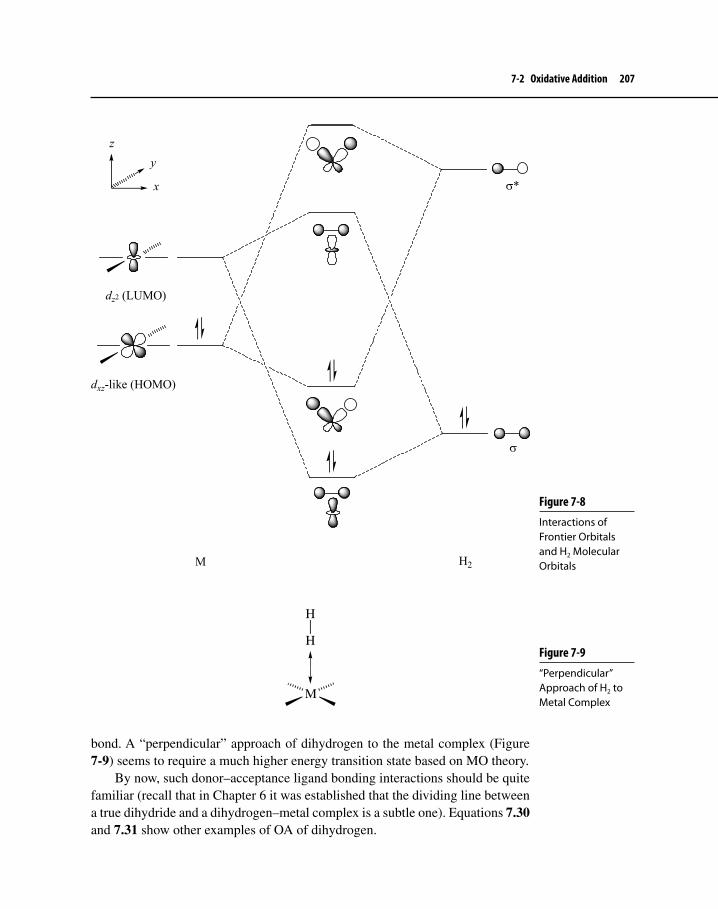
7-2 Oxidative Addition 207
Figure 7-8 Interactions of Frontier Orbitals and H2 Molecular Orbitals
dxz-like (HOMO)
dz2 (LUMO)
σ*
σ
M H2
z
y
x
bond. A “perpendicular” approach of dihydrogen to the metal complex (Figure 7-9) seems to require a much higher energy transition state based on MO theory.
By now, such donor–acceptance ligand bonding interactions should be quite familiar (recall that in Chapter 6 it was established that the dividing line between a true dihydride and a dihydrogen–metal complex is a subtle one). Equations 7.30 and 7.31 show other examples of OA of dihydrogen.
Figure 7-9“Perpendicular” Approach of H2 to Metal Complex
M
H
H

208 Chapter 7 Organometallic Reactions I
IrTPPMS
C TPPMS
Cl
TPPMS:
SO3− Κ+
Ph2P
H2
H2OIr
TPPMS
C TPPMS
H
H
Cl
O O
7.30
(dppe)Ir(CO)Br + H2
4
IrBr
HPh2P
PPh2
H
C
IrH
CPh2P
PPh2
H
Br
5 6
O
O
7.31
Equation 7.30 demonstrates the increasing use of the green solvent H2O (see Section 9-1-5 for more discussion on green chemistry) as a reaction medium for organometallic reactions; in this case the product is the result of syn addition of H2, which is exactly the same result observed in organic solvents.62 The TPPMS (triphenylphosphine m-monosulfonate) group attached to phosphorus makes both the phosphine and the resulting Ir complex water soluble.
The addition of H2 to complex 4 to yield 5 is interesting (equation 7.31). Originally, it was thought that 5 formed under kinetic control by parallel addi-tion of H2 along the P−Ir−CO axis. Rearrangement of 5 to its thermodynami-cally more stable diastereomer 6 occurred via reversible loss of H2, followed by OA again of H2 parallel to the P−Ir−Br axis. Closer examination of the reaction revealed that the rearrangement of 5 to 6 also involved a bimolecular reaction between 4 and 5.63
62D. R. Paterniti, P. J. Roman, Jr., and J. D. Atwood, Organometallics, 1997, 16, 3371.63C. E. Johnson and R. J. Eisenberg, J. Am. Chem. Soc., 1985, 107, 3148; and A. J. Kunin, C. E. Johnson, J. A. Maquire, W. D. Jones, and R. Eisenberg,., 1987, 109, 2963; for recent work involving addition of H2 to Ir complexes with chiral diphosphine ligands, see A. Ç. Atesin, S. B. Duckett, C. Flaschenriem, W. W. Brennessel, and R. Eisenberg, Inorg. Chem., 2007, 46, 1196.
Exercise 7-4 a. Verify that compound 5 forms by parallel addition of H2 along the P−Ir−CO axis and 6 forms as a result of H2 adding parallel to the P−Ir−Br axis.
b. Why is compound 6 more stable than 5?

7-2 Oxidative Addition 209
Addition of C–HAlthough intra- or intermolecular OA of a C−H bond to a metal (equation 7.32) is not, strictly speaking, the addition of a symmetrical addendum,64 it is a reaction where the C−H bond of the oxidizing agent possesses electronic characteristics similar to that of the H−H bond.
LnM + R−H LnM(R)(H)
or
LnMC
H
LnM
HC
R = alkyl, aryl, vinyl, alkynyl
7.32
The study of C−H bond OA, also called C–H bond activation, represents an area of research that has seen an enormous increase in activity over the past 20 years. These efforts have given us numerous examples of the addition of a C−H bond (especially intermolecular addition) to a transition metal and have increased our understanding of the reaction mechanisms involved.65 C−H acti-vation is important because it allows direct binding to occur between a metal and a relatively abundant and normally unreactive organic molecule (e.g., methane, ethane, or benzene). Subsequent transformations of the resulting C−M bond lead to substituted hydrocarbons containing a variety of functional groups that would be difficult to introduce directly on the free hydrocarbons themselves by conventional organic chemistry (for example, the conversion of CH4 to CH3OH). We will see several examples of such transformations in later chapters. Moreover, if C−H bond activation and subsequent transformation are catalytic in transition metals, then the process could become chemically selec-tive, economical, and green.
Examples of intramolecular C−H activation (or cyclometallation) were initially more common than intermolecular cases, probably due to the favor-able entropy effect of having both the metal and the C−H group within the same molecule, but work in recent years has provided numerous intermolecular C−H activation transformations. Regardless of the mode of addition, C−H activation is inherently more difficult than OA of dihydrogen for several reasons.
Table 7-6 shows that transition metal–hydrogen bonds are typically stronger (but not always significantly stronger) than M−C bonds, and both types of bonds
64The group, X−Y, adding to the metal is called the addendum or the oxidizing agent.65For reviews that give examples of C-H bond activation, see R. H. Crabtree, J. Chem.. Soc. Dalton Trans., 2001, 2437; V. Ritleng, C. Sirlin, and M. Pfeffer, Chem Rev., 2002, 102, 1731; and C.-H. Jun and J. H. Lee, Pure Appl. Chem., 2004, 76, 577.

210 Chapter 7 Organometallic Reactions I
usually increase in strength as one goes down a column in the periodic table.66 Because the H−H bond (BDE = 104 kcal/mol) and a C−H bond (BDE is up to 105 kcal/mol) are roughly comparable in energy, the resulting LnM(H)(H) adduct typically possesses more bond energy than the comparable LnM(R)(H) product. The former process is thus usually more feasible thermodynamically.
As the C−H bond approaches the metal, steric hindrance is greater than that from the approach of dihydrogen, so one might expect that steric hindrance may cause C−H activation to be kinetically less feasible than OA of H2. Indeed, work-ers have shown that it is the bond between a primary alkane carbon and hydrogen that is more likely to add to the metal rather than bonds between hydrogen and secondary or tertiary carbons.
From a molecular orbital standpoint, it is possible to do an analysis of C−H OA similar to that for addition of H2 (Figure 7-8). The non-spherical nature of the σ C−H bonding orbital, however, makes its overlap with the metal’s empty dz2-like orbital or dsp-hybridized orbital (dσ) of comparable symmetry less favorable than that of the σ (H2) orbital (Figure 7-10). Also, the interaction of the filled dxz-like metal orbital (dπ) with the C−H σ* orbital (back-bonding) is weaker because the latter orbital is unsymmetrical, not directed toward the metal, and less spherical in nature than the comparable dihydrogen orbital;
66The following two papers compare M−C and H−C bond strengths on the basis of high-level MO calculations: E. Clot, C. Mégret, O. Eisenstein, and R. N. Perutz, J. Am. Chem. Soc., 2006, 128, 8350 and M. Mitoraj, H. Zhu, A. Michalak, and T. Ziegler, Organometallics, 2007, 26, 1627.
Table 7-6 Selected Experimentally Derived M–H and M–C Bond Dissociation Energies (kcal/mol) Compared with Those of C–H and C–C Bondsa,b
C–H 85 → 105 (H–allyl → CH3–H)
Ti–Hc 45 Cp(CO)3Cr–H 62 (CO)4Co–H 66Cp*
2(H)Zr–H 78 Cp(CO)3Mo–H 69 Cp(CO)2Rh+–H 69Cp*
2(H)Hf–H 80 Cp(CO)3W–H 72 (CO)(PPh3)Cl2Ir–H 59
C–C 75 →93 (C–allyl → C–Ph)
Ti–CH3c 42 Cr–CH3
c 34 Co–CH3c 42
Cp* (CH3)2Zr–CH3 66 Cp(CO)3Mo–CH3 48 Rh+–CH3c 34
Cp*(CH3)2Hf–CH3 70 W+–CH3c 53 Ir+–CH3
c 75
aData taken from J. Uddin, C. M. Morales, J. H. Maynard, and C. R. Landis, Organometallics, 2006, 25, 5566.bDetermined at 298 K unless otherwise specified.cDetermined at 0 K by ion beam mass spectrometry.

7-2 Oxidative Addition 211
overall, therefore, C−H bonds tend to be weaker σ donors and π acceptors than H−H bonds.67
Based on the simple MO analysis described above and analogous to the addition of H2, the simplest mechanism for C−H activation would be a one-step, concerted three-center addition of the C−H bond to a metal complex. Calculations and experiment, however, suggest a more complicated picture. As the C−H bond approaches the metal, a σ-complex intermediate forms, which then goes through a three-center transition state to give the adduct (Scheme 7.4).68 If another hydrocarbyl group69 is already attached to the metal, an exchange of R groups
67K. Krogh-Jespersen and A. S. Goldman, “Transition States for Oxidative Addition to Three-Coordinate Ir(I): H−H, C−H, C−C, and C−F Bond Activation Energies,” In Transition State Modeling for Catalysis, D. G. Truhlar and K. Morokuma, Eds., ACS Symposium Series 721, American Chemical Society: Washington, D. C., 1999, pp. 151–172.68S. Sakaki, Topics in Organomet. Chem., 2005, 12, 31; E. S. Xavier, W. B. De Almeida, J. C. S. da Silva, and W. Rocha, Organometallics, 2005, 24, 2262; and S. Bi, Z. Zhang, and S. Zhu, Chem. Phys. Lett., 2006, 431, 385.69The word “hydrocarbyl” is used to describe a σ-bonded hydrocarbon ligand that may be an alkyl, aryl, or vinyl group, for example.
Figure 7-10 Interactions of Frontier Metal and C−H Molecular OrbitalsM
C H HC
M
dσ
σ (C−H) σ∗ (C−H)
dπ
Scheme 7.4C−H Activation Mechanistic Pathways
LnM CH3
R-H
LnM
CH3
R
HLnM
RH
CH3
LnM
RH
CH3
LnM R
+ CH4
REσ-complex
LnMCH3
R
H
OA-RE
σ-Bond Metathesis

212 Chapter 7 Organometallic Reactions I
can occur via a reductive elimination reaction (Section 7-3). Other mechanistic paths are possible, and one in particular is also shown in Scheme 7.4—σ-bond metathesis. Note that this mechanism does not require a change in oxidation state of the metal. This latter pathway is likely for early d0 transition metal complexes, where the OA mechanism is not available, but it has also been suggested as a mechanistic possibility for some C−H activations involving middle to late transi-tion metals.70 Sigma bond metathesis is a very important fundamental organome-tallic reaction, which we will see again in Chapter 11.
The reaction described in equation 7.33 exemplifies intramolecular C−H activation (cyclometallation) followed by reductive elimination (see Section 7-3) of neopentane.71 Another more recent example (equation 7.34) was designed to demonstrate intramolecular competition between aryl C−H and alkyl C−H bond activation.72 Interestingly, in this case, alkyl C−H addition to the metal occurred to the exclusion of aryl C−H addition, although other experimental work and theoretical investigations indicate that the preference for either intra or inter-molecular C−H activation is to be C−H (sp2 aryl or vinyl) > Io C−H (sp3) > IIo C−H (sp3) > IIIo C−H (sp3) > Io C−H (sp3 allyl or benzyl), a trend that is in accord with decreasing C−H bond dissociation energy.73 Relief of steric crowding when a C−H bond from the bulky tert-butyl group reacts rather than the aryl C−H group was offered as a possible explanation for the unusual preference shown.
The years 1982 and 1983 saw exciting new developments in direct intermolecular C−H activation when three research groups independently reported similar alkane C−H additions to electron-rich 16-electron Ir(I) and
70For a review and discussion of various C−H activation mechanisms, see M. Lersch and M. Tilset, Chem. Rev., 2005, 105, 2471; R. N. Perutz, B. A. Vastine and M. B. Hall, J. Am. Chem. Soc., 2007, 129, 12068; and S. Sabo-Etienne, Angew. Chem. Int. Ed., 2007, 46, 2578.71J. A. Ibers, R. DiCosimo, and G. M. Whitesides, Organometallics, 1982, 1, 13.72R. Corberán, M. Sanaú, and E. Peris, Organometallics, 2006, 25, 4002.73J. S. Owen, J. A. Labinger, and J. E. Bercaw, J. Am. Chem. Soc., 2006, 128, 2005 and M. Mitoraj, J. Zhu, A. Michalak, and T. Ziegler, Organometallics, 2007, 26, 1627.
(Et3P)2Pt
HPEt3
(Et3P)Pt
H
(Et3P)Pt
H
(Et3P)2Pt
+ Me4C
RE
Intramolecular OA
Ox. State: +2
e− Count: 16
+2
14
+4
16 16
PEt3
+2
7.33

7-2 Oxidative Addition 213
Rh(I) complexes. Equations 7.35,74 7.36,75 and 7.3776 show these results. All the examples first involve production of a reactive, electron-rich, 16-electron com-plex by photoactivated reductive elimination of H2 or loss of a neutral ligand. This is a rather general reaction for a variety of alkanes and arenes that react not only with Ir and Rh complexes, but also with low-valent Ru, Pt, and Os complexes.
MeMeMe
Me Me
IrMe3P
H
Hhν
MeMeMe
Me Me
IrMe3P H
+ H2
7.35
MeMeMe
Me Me
IrC
hν
MeMeMe
Me Me
IrC H
+ CO
C
H
O O O
7.36
74A. H. Janowisz and R. G. Bergman, J. Am. Chem. Soc., 1982, 104, 352.75J. K. Hoyano and W. A. G. Graham, J. Am. Chem. Soc., 1982, 104, 3723.76W. D. Jones and F. J. Feher, Organometallics, 1983, 2, 562.
N N1) Ag2O/CH2Cl2/25 oC
2) [IrCp*Cl2]2 Ir
Cp*
Cl
Cl
N
N
Cl−
Ir
Cp*
N
N
Cl + HCl
H
H
N
IrN
Cp*
Cl
+ HCl
(Transient intermediate)
AromaticC−H activation
Aliphatic C−H activation
PhPh
7.34

214 Chapter 7 Organometallic Reactions I
MeMeMe
Me Me
IrMe3P
H
H hν/−50o C
MeMeMe
Me Me
IrMe3P H
+ H2CH3CH2CH3
7.37
More recently, Bergman’s group has expanded the scope of C−H activation using Ir(III) complexes, which are not as electron rich as the Ir(I) complexes, as illus-trated in Scheme 7.5. The starting material contains a weakly coordinating ligand (CF3SO2
–, also known as triflate and abbreviated OTf), which is easily lost, pro-ducing a 16-e– reactive intermediate. The presence of a CH3 ligand in the starting material allows for loss of CH4 by reductive elimination, which is a driving force for the overall reaction whose last step is 1,2-elimination. Despite the lack of electron richness of the Ir(III) complex, the reaction produces a strong M−C bond because third-row transition metals tend to form the strongest M−C and M−H bonds (vide supra—Table 7-6). This is another driving force for the reaction. The initial oxidative addition product is not observed, but its existence is implied by the nature of the products obtained. Detailed experimental77 and theoretical investigations78 showed that the mechanism most likely goes through an Ir(V) intermediate after OA, which is followed by a reductive elimination to form CH4. The alternate pathway involving a σ bond metathesis probably does not occur.
In general, intermolecular C−H OA is favorable if (1) the metal complex is coordinatively unsaturated, (2) the metal complex is relatively sterically uncon-gested, (3) the metal is a second- or preferably a third-row element, (4) electron-rich PR3 ligands are attached to the metal such that the R groups on the phosphine are resistant to cyclometallation (e.g., R = CH3, and (5) the metal has a filled orbital capable of interacting with the σ* antibonding orbital of the C−H bond.79 C−H activation continues to be a very active area of research, and a major goal
77S. R. Klei, T. D. Tilley, and R. G. Bergman, J. Am. Chem. Soc., 2000, 122, 1816 and P. Burger and R. G. Bergman, J. Am. Chem. Soc., 1993, 115, 10462.78S. Niu and M. B. Hall, J. Am. Chem. Soc., 1998, 120, 6169.79R. H. Crabtree, Chem. Rev., 1985, 85, 245.
Exercise 7-5 Propose a structure for the final product in Scheme 7.5 if the hydrocarbon added in the first step were benzene instead of ethane.

7-2 Oxidative Addition 215
is now to make this reaction both specific for particular C−H bonds and catalytic with regard to the transition metal complex. The reactions above are stoichiometric, but we will see examples of transition metal-catalyzed C−H bond activations in later chapters.80
Addition of C–COxidative addition of a C−C bond (C−C bond activation) to a metal, like C−H addition, is potentially very important on both a laboratory and an industrial scale. If a metal complex were available that could react via OA with a specific alkane C−C bond, for example, the ultimate result would be exclusive functional-ization of a normally unreactive carbon atom. Once that occurs, there are numer-ous transformations available to convert the M−C bond to other functionalities. Catalytic activation of C−C bonds in long-chain hydrocarbons found in petro-leum could provide low-energy, efficient routes to production of compounds that are useful in gasoline refining. Unfortunately, unstrained C−C bonds—the type found in saturated hydrocarbons—typically do not readily undergo OA for the same reasons associated with lack of reactivity of C−H bonds. In fact, the situa-tion ought to be worse with C−C bond activation, because OA now produces not one but two M−C bonds at the expense of breaking a robust C−C bond. There should, moreover, be more steric hindrance created when a C−C bond approaches
80It must be pointed out that there are other complications regarding the addition of alkyl C−H bonds to a metal. The resulting metal alkyl complex could undergo either reductive elimination back to starting material (Section 7-3) or, if a β C−H bond is present, rapid 1,2-elimination (see Scheme 7.5, Section 6-1-1, and Chapter 8). The latter outcome may not be so bad, however, if the goal of C−H activation is to convert an alkane to an alkene, a compound possessing a functional group associated with a rich chemistry. See O. Eisenstein and R. H. Crabtree, New. J. Chem., 2001, 25, 665, for a discussion of the interplay between 1,2-elimination and RE after C−H activation has occurred.
Scheme 7.5 C−H Activation of an Ir(III) complex
MeMeMe
Me Me
IrMe3P
Me
OTf
CH3CH2−H
MeMeMe
Me Me
IrMe3P
MeOTf−CH2CH3
H
+OTf− Me
MeMe
Me Me
IrMe3P
CH2CH3
OTf
MeMeMe
Me Me
IrMe3P H
+OTf−
1,2-elimination
(V)(III) (III)
(III)
REOA
CH4

216 Chapter 7 Organometallic Reactions I
a metal complex compared with a C−H bond. Finally, the orbital interactions between a C(sp3)–C(sp3) bond and a metal are either not as favorable or about as favorable as those existing with the approach of C(sp3)−H to a metal complex. Most examples of C−C OA have involved the reaction of cyclic hydrocarbons with at least one highly strained, relatively weak C−C bond. Here, relief of ring strain is a driving force in the reaction. Several such examples follow.
Reaction of the platinum complex known as Zeise’s dimer with bicyclo[1.1.0]butane, which contains a highly strained bridging bond, gives the corresponding platinabicyclo[1.1.1]pentane (7) (equation 7.38) as a stable, crystalline solid.81
+ [PtCl2(H2C=CH2)]2
H2C=CH2
[PtCl2(C4H6)]nPyridine
(2 equivalents)
PtPy
PyCl
Cl7
7.38
Equation 7.39 describes a transformation with first the C−H bond of cyclopro-pane adding to the Rh complex, followed by RE of H2, and then rearrangement to give the rhodacyclobutane.82 Metallacyclobutanes are thought to be intermediates in some alkene polymerization and metathesis reactions; these compounds will appear again in Chapter 11.
(Cp*)(PMe3)RhH2 +
H2
hν(Cp*)(PMe3)Rh
H
H
(Cp*)(PMe3)Rh
7.39
Using the same Ir(III) complex shown in Scheme 7.5, Bergman was able to demonstrate that direct C−C bond activation occurred (equation 7.40).83
MeMeMe
Me Me
IrMe3P
Me
OTf
H
Ot-Bu (Me3P)Ir
Me
HOt-Bu
Cp*
C−C bondactivation
(Me3P)Ir
Me
H Ot-Bu
RE
Ir
Cp*
Me3P
Me
H
OTf−
Cp*
OTf−
7.40
Although readers might expect that C−H bond activation would lead to a more stable adduct than OA of a C−C bond, and thus always be preferred in systems where there is a choice between the two modes of activation, that is not
81A. Miyashita, M. Takahashi, and J. Takaya, J. Am. Chem. Soc., 1981, 103, 6257.82R. A. Periana and R. G. Bergman, J. Am. Chem. Soc., 1986, 108, 7346.83M. R. Anstey, C. M. Yung, J. Du, and R. G. Bergman, J. Am. Chem. Soc., 2007, 129, 776.

7-2 Oxidative Addition 217
always the case. The last 10–15 years have seen many more examples of C−C bond activation, some of which do not involve reaction of strained C−C bonds. The following two cases indicate that C−C bond activation is not only competitive with OA of C−H, but may even be preferred. Equation 7.41 shows the Rh com-plex first undergoing OA of an aryl C−H bond to give the first product. Further heating over time produces the thermodynamically-more-stable, five-membered ring metallacycle that resulted from C−C bond activation.84
+ Cp*Rh(PMe3)(Ph)(H)
Ph−HRh
Cp*
HMe3P
85 oC/5 days65 oC/12 h
Rh
Me3P Cp*
7.41
Milstein and co-workers85 have studied OA and RE reactions of Rh and Ir complexes containing tridentate pincer ligands, which are generalized as structure 7a; 7b shows a specific pincer ligand type called PCP (two phosphorous atoms and a carbon bond to the metal). Such ligands resist degradation at relatively high temperatures and possess a huge variety of steric and electronic properties as a result of varying the substituents on the heteroatom Y and Z groups.86 The high steric bulk of the tert-butyl groups on phosphorus of the particular t-BuPCP ligand used in Scheme 7.6 brings the substituted benzene into close proximity to the metal and allows direct comparison of the OA of a benzylic C−H bond and an aryl−CH3 bond.
Y
Z
M
Y, Z = P, N, S
7a
PR2
PR27b
84C. Perthuisot and W. D. Jones, J. Am. Chem. Soc., 1994, 116, 3647.85B. Rybtchinski and D. Milstein, Angew. Chem. Int. Ed., 1999, 38, 870 and B. Rybtchinski, A. Vigalok, Y. Ben-David, and D. Milstein, J. Am. Chem. Soc., 1996, 118, 12406.86For a recently-published book containing numerous examples of C−H and C−H activation as well as several other organometallic reactions involving pincer ligands, see D. Morales-Morales, The Chemistry of Pincer Compounds, Elsevier: Amsterdam, 2007.

218 Chapter 7 Organometallic Reactions I
Even at room temperature, product 8, the result of C−C bond activation, formed along with compound 9 (C−H activation). Continued reaction after several hours resulted in conversion of 9 to 8. The experiment suggested that the kinetic barri-ers to C−H and C−C activation were indeed similar, and that overall there was a thermodynamic preference for C−C activation.
In addition to the stoichiometric C−C OA reactions discussed so far, there are now numerous examples of catalytic transformations where at some point in the catalytic cycle a C−C bond activation occurs. Some of these are quite useful to synthesis chemists.87
87For a review of catalytic C−C bond activation, see C.-H. Jun, Chem. Soc. Rev., 2004, 33, 610.
CH3
Me
Me
P(t-Bu)2
P(t-Bu)2
Rh
Me
Me
P(t-Bu)2
P(t-Bu)2
Me
Me
P(t-Bu)2
P(t-Bu)2
Rh
H
Cl
Cl
H3C
Several hours25 oC
[RhL2Cl]2
25 oC
8
9
L = H2C=CH2
2 L
2 L
Scheme 7.6C–C Bond Activation with a PCP-Rh Complex
Exercise 7-6 Suggest two reasons why the reactions described in Equation 7.41 and Scheme 7.6 might be favorable thermodynamically compared with addition of a relatively unstrained C(sp3)−C(sp3) bond to the same metals.
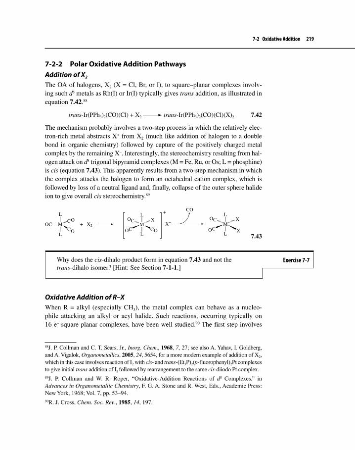
7-2 Oxidative Addition 219
7-2-2 Polar Oxidative Addition PathwaysAddition of X2
The OA of halogens, X2 (X = Cl, Br, or I), to square–planar complexes involv-ing such d8 metals as Rh(I) or Ir(I) typically gives trans addition, as illustrated in equation 7.42.88
trans-Ir(PPh3)2(CO)(Cl) + X2 trans-Ir(PPh3)2(CO)(Cl)(X)2 7.42
The mechanism probably involves a two-step process in which the relatively elec-tron-rich metal abstracts X+ from X2 (much like addition of halogen to a double bond in organic chemistry) followed by capture of the positively charged metal complex by the remaining X–. Interestingly, the stereochemistry resulting from hal-ogen attack on d8 trigonal bipyramid complexes (M = Fe, Ru, or Os; L = phosphine) is cis (equation 7.43). This apparently results from a two-step mechanism in which the complex attacks the halogen to form an octahedral cation complex, which is followed by loss of a neutral ligand and, finally, collapse of the outer sphere halide ion to give overall cis stereochemistry.89
OC MC
CL
L
+ X2 MC
C X
C
L
L
CO+
X− MC
C X
X
L
L
O
O
O
O O
O
O
7.43
Oxidative Addition of R–XWhen R = alkyl (especially CH3), the metal complex can behave as a nucleo-phile attacking an alkyl or acyl halide. Such reactions, occurring typically on 16-e– square planar complexes, have been well studied.90 The first step involves
88J. P. Collman and C. T. Sears, Jr., Inorg. Chem., 1968, 7, 27; see also A. Yahav, I. Goldberg, and A. Vigalok, Organometallics, 2005, 24, 5654, for a more modern example of addition of X2, which in this case involves reaction of I2 with cis- and trans-(Et3P)2(p-fluorophenyl)2Pt complexes to give initial trans addition of I2 followed by rearrangement to the same cis-diiodo Pt complex.89J. P. Collman and W. R. Roper, “Oxidative-Addition Reactions of d8 Complexes,” in Advances in Organometallic Chemistry, F. G. A. Stone and R. West, Eds., Academic Press: New York, 1968; Vol. 7, pp. 53–94.90R. J. Cross, Chem. Soc. Rev., 1985, 14, 197.
Why does the cis-dihalo product form in equation 7.43 and not the trans-dihalo isomer? [Hint: See Section 7-1-1.]
Exercise 7-7

220 Chapter 7 Organometallic Reactions I
nucleophilic displacement of the leaving group followed usually (but not always) by combination of the leaving group and substituted metal complex, the prototyp-ical example of which appeared in Scheme 7.3 (Section 7–2), where CH3I adds to Vaska’s compound. Another excellent example of OA of CH3I to a metal occurs as a key step in the Monsanto acetic acid synthesis (to be discussed in Chapter 9), shown in equation 7.44.
CH3I + [Rh(CO)2(I)2]− RhC
I C
I
CH3
I
O
O
7.44
The overall effect of the reaction results in the addition of R−X to the metal. Substrate types that will undergo this mode of OA are generally limited to R = benzyl, allyl, and methyl. Some acyl compounds [R(C=O)−X] also readily undergo OA. These are the same substrates that are most reactive in SN2 dis-placements or in nucleophilic acyl substitution. Other characteristics of these OA reactions associated with the SN2 pathway include the following:
second-order kinetics (first order with respect to metal complex and first • order in alkyl halide);dependence of rate on leaving group ability: X = CF• 3SO3 > I > tosylate ~Br > Cl;large negative entropies of activation (−40 to −50 eu);• increase in rate when phosphine ligands are present and modified to be • more electron releasing (e.g., PMe3 or PEt3);dependence of rate on solvent (polar solvents increase the rate);• retardation of the rate of reaction due to increasing steric bulk of ligands • already attached to the complex; andisolation, in certain instances, of ionic intermediates such as • 10,91 the result expected after the nucleophilic displacement of the leaving group.
IrR
PPh3
C
+I−
10
CpIr(CO)(PPh3) + R−I R = Me, BenzylO
91J. W. Kang and P. M. Maitlis, J. Organometal. Chem., 1971, 26, 393 and A. J. Oliver and W. A. G. Graham, Inorg. Chem., 1970, 9, 2653.

7-2 Oxidative Addition 221
The evidence described above is strongly suggestive of an SN2 displacement mechanism exactly analogous to its counterpart in organic chemistry. The one piece missing from this mechanistic puzzle is an examination of the stereochem-istry at the carbon atom of the substrate. Probably the most convincing evidence for an SN2 pathway would be the unambiguous demonstration of the occurrence of inversion of configuration at the carbon bearing the leaving group. Until about 30 years ago, clear-cut examples of inversion of configuration taking place upon OA of R−X were lacking. Making up for this deficiency, the detailed studies by Stille et al.92 on OA of substituted benzyl halides onto palladium complexes pro-vided the first unambiguous examples of inversion of configuration taking place during attack on the substrate by a metal.
Scheme 7.7 illustrates the reactions carried out by the Stille group. Up to the time of the study, the stereochemistry of all steps in the reaction sequences, except that of OA, had been established. Thus, inversion of configuration to yield 11 or 12 must have occurred in the first step, since (1) the next step going to 13 or 14 is carbonyl insertion (to be discussed in detail in Chapter 8), known to occur with retention of configuration, and (2) the final step, called metha-nolysis, proceeds without disturbing a bond at the carbon stereogenic center. The alternate sequence through the middle of the scheme shows a carbonylated complex, 15, reacting with the alkyl halide, producing an intermediate that already has a carbonyl ligand on the metal. Rearrangement involving carbonyl
92J. K. Stille and K. S. Y. Lau, Acc. Chem. Res., 1977, 10, 434.
Scheme 7.7 Stereospecific Reactions of Palladium Complexes
L
Pd XC
L
Ph
R
H
CC
Ph
R
H
O L
Pd X
L
CO
(retention)
CX
Ph
R
H
L 4Pd
(inve
rsion
)
L3PdCO
(inversion)
C
Pd XC
L
Ph
R
H
(rete
ntio
n)
CC
Ph
R
HOMe
O
MeOH
(retention)
11
L*
Pd XC
L*
Ph
R
H12
CO
(retention)CC
Ph
R
H
O L*
Pd X
L*
MeO
H(re
tentio
n)
16
13
14
15L *4 Pd
(inversion)
R = D or CH3; L = PPh3; L* = PEt3; X= Br or Cl
O

222 Chapter 7 Organometallic Reactions I
insertion resulting in retention of configuration of the migrating alkyl group fol-lowed by methanolysis yields the same product, 16. By comparing the optical purity and absolute configuration of the starting alkyl halides to those of 16, the change at the stereogenic center was clearly inversion of configuration. These studies also found that the order of reactivity of benzyl halides was PhCH2Br > PhCH2Cl > PhCHBrCH3 > PhCHClCH3. This is consistent with the order expected for an SN2 reaction, because Br is a better leaving group than Cl and primary substrates react faster than secondary substrates. Stille also reported that the more electron-rich the metal, the faster the reaction, again consistent with an SN2 pathway.
Within the past 10 years, there have been several reports on high-level molec-ular orbital calculations (mainly at the DFT level) being used to investigate the pathway of OA of CH3I to a variety of transition metal complexes. This work corroborates the work of Stille’s group by indicating that the SN2 mechanism is the lowest energy pathway.93
What about unactivated C−X bonds, such as those found in aryl halides, which also readily undergo OA? In Chapter 12 we will see many useful syn-thetic transformations where OA of an aryl C−X bond is the first step in a catalytic cycle. The SN2 pathway is not available for aryl halides, so another mode of addition must occur. Especially informative studies have been reported on the OA of Ar−X to L2Pd (L = phosphine), which is often involved in the catalytic cycles mentioned above. These investigations94 have shown that OA occurs after dissociation of one of the L ligands, and calculations95 not only corroborate the experimental work, but also suggest that the step involving OA is probably more like the three-centered, concerted step found with C−H and C−C addition.
7-2-3 Radical PathwaysMechanistic pathways that involve radical intermediates may accompany SN2-type polar oxidative additions. Under certain conditions, such pathways may
93M. Feliz, Z. Freixa, P. W. N. M. van Leeuwen, and C. Bo, Organometallics, 2005, 24, 5718; T. R. Griffin, D. B. Cook, A. Haynes, J. M. Pearson, D. Monti, and G. E. Morris, J. Am. Chem. Soc., 1996, 118, 3029; and M. Cheong, R. Schmid, and T. Ziegler, Organometallics, 2000, 19, 1973.94A. H. Roy and J. F. Hartwig, Organometallics, 2004, 23, 1533 and F. Barrios-Landeros and J. F. Hartwig, J. Am. Chem. Soc., 2005, 127, 6944.95M. Ahlquist, P. Fristrup, D. Tanner, and P.-O. Norrby, Organometallics, 2006, 25, 2066 and K. C. Lam, T. B. Marder, and Z. Lin, ibid., 2007, 26, 758.
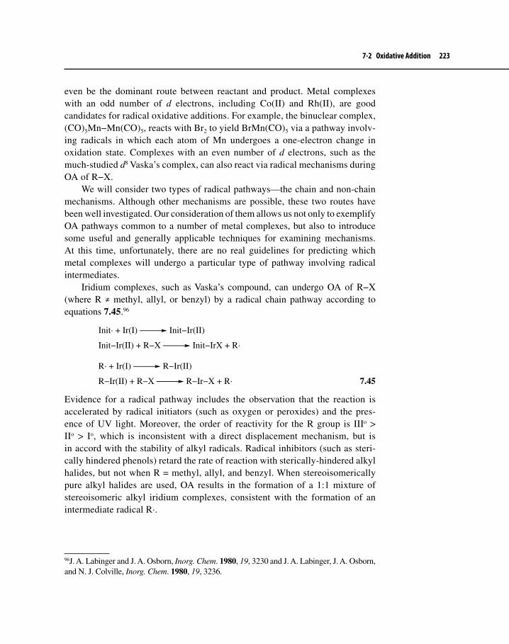
7-2 Oxidative Addition 223
even be the dominant route between reactant and product. Metal complexes with an odd number of d electrons, including Co(II) and Rh(II), are good candidates for radical oxidative additions. For example, the binuclear complex, (CO)5Mn−Mn(CO)5, reacts with Br2 to yield BrMn(CO)5 via a pathway involv-ing radicals in which each atom of Mn undergoes a one-electron change in oxidation state. Complexes with an even number of d electrons, such as the much-studied d8 Vaska’s complex, can also react via radical mechanisms during OA of R−X.
We will consider two types of radical pathways—the chain and non-chain mechanisms. Although other mechanisms are possible, these two routes have been well investigated. Our consideration of them allows us not only to exemplify OA pathways common to a number of metal complexes, but also to introduce some useful and generally applicable techniques for examining mechanisms. At this time, unfortunately, there are no real guidelines for predicting which metal complexes will undergo a particular type of pathway involving radical intermediates.
Iridium complexes, such as Vaska’s compound, can undergo OA of R−X (where R ≠ methyl, allyl, or benzyl) by a radical chain pathway according to equations 7.45.96
Init· + Ir(I) Init−Ir(II)
Init−Ir(II) + R−X Init−IrX + R·
R· + Ir(I) R−Ir(II)
R−Ir(II) + R−X R−Ir−X + R· 7.45
Evidence for a radical pathway includes the observation that the reaction is accelerated by radical initiators (such as oxygen or peroxides) and the pres-ence of UV light. Moreover, the order of reactivity for the R group is IIIo > IIo > Io, which is inconsistent with a direct displacement mechanism, but is in accord with the stability of alkyl radicals. Radical inhibitors (such as steri-cally hindered phenols) retard the rate of reaction with sterically-hindered alkyl halides, but not when R = methyl, allyl, and benzyl. When stereoisomerically pure alkyl halides are used, OA results in the formation of a 1:1 mixture of stereoisomeric alkyl iridium complexes, consistent with the formation of an intermediate radical R·.
96J. A. Labinger and J. A. Osborn, Inorg. Chem. 1980, 19, 3230 and J. A. Labinger, J. A. Osborn, and N. J. Colville, Inorg. Chem. 1980, 19, 3236.

224 Chapter 7 Organometallic Reactions I
Stereochemical Probes
The stereochemical outcome of a reaction can suggest much about its mechanistic pathway. If a molecular fragment, whose stereochemistry is clearly defined, can be attached to the reactant and remain attached during the course of the reaction without affecting the chemistry, then determination of product stereochemistry can be straight-forward using spectroscopic means.
For example, the two primary alkyl bromides, 17 and 18 (Figure 7-11), are diaste-reomerically related, the former is called erythro and the latter threo. The designations erythro and threo arise from the corresponding simple sugars, erythrose and threose, 19 and 20. These bromides serve as useful probes, because the possible stereochemical out-comes of retention, inversion, or racemization at the carbon bearing the bromide may be readily determined by NMR spectroscopy without requiring the use of optically active compounds. Starting with 18 (R = D, R* = tert-butyl), we would expect the stereochemistry found in 21 if retention of configuration occurred upon OA. Note that the only reasonable conformation for product requires that the bulky tert-butyl group be anti to the metal. Inversion of configuration would give 22. We can distinguish between 21 and 22 by the measuring the magnitude of the coupling constant between the two vicinal protons H1
Figure 7-11 Stereochemical Probes
R*
H R
Br
H D
CHO
H OH
CH2OH
H OH
CHO
HO H
CH2OH
H OH
HR
R*
DH
Br
R*
R HBr
DH
R*
R H
Br
H D
RH
R*
DH
Br
R*
H RBr
DH
R*
H2 DIrLn
DH1
R*
H2 DIrLn
H1D
17 Erythro 18 Threo
19 Erythrose 20 Threose
gauche orientationof protons
anti orientationof protons
21 22R* = tert-Bu or PhR = D or F

7-2 Oxidative Addition 225
and H2 and then applying the Karplus97 relationship. Finally, if racemization occurs, the NMR spectra of product will be identical, regardless of whether we start from 17 or 18, because equal molar amounts of 21 and 22 will be present.
Variations of 17 and 18 have also been used as probes where R = F and R* = phenyl. Fluorine, like hydrogen, has a spin of 1/2 and couples with the vicinal proton. Fluorine–hydrogen coupling constants are significantly larger than those for vicinal hydrogens. Using the Karplus relation, it is relatively easy to discern anti versus gauche orientation of adjacent protons.
Another mechanistic possibility involving radical intermediates is the non-chain mechanism as outlined in equations 7.46.98
M(PPh3)3 M(PPh3)2 + PPh3
M(PPh3)2 + R−X ·M(X)(PPh3)2 + R· (slow)
·M(X)(PPh3)2 + R· RM(X)(PPh3)2 (fast)
M = Pd, Pt 7.46
Two observations suggest a mechanism involving radical intermediates. First, a stereorandomization occurs at R. For instance, if R is chiral and one starts with the S enantiomer, the resulting product, RMXLn-1, is racemic. Second, the rates of reaction as a function of the structure of R decrease according to R = IIIo > IIo> Io. Since this also corresponds to the order of stability of alkyl radicals, the observation is consistent with the presence of radical intermediates. On the other hand, we can distinguish non-chain pathways from chain mechanisms because the former are not subject to rate change resulting from the addition of radical scavengers or initiators.
Oxidative addition is complex in terms of the mechanistic possibilities avail-able. Subtle variations in reaction conditions can result in a change in mechanism. Some symmetrical addenda (H2) or those with nonpolar bonds involving elec-tropositive non-metals (C−H or C−C) seem to undergo addition by a concerted
97M. Karplus, J. Am. Chem. Soc., 1963, 85, 2870. Karplus reported a relationship between the coupling constant of vicinal protons and the dihedral angle described by these adjacent nuclei. Coupling is maximal when the dihedral angle (ϕ) = 0o or 180o and minimal when ϕ = 90o.
H
H
φ
φ = dihedral angle
98A. V. Kramer, J. A. Labinger, J. S. Bradley, and J. A. Osborn, J. Am. Chem. Soc., 1974, 96, 7145 and A. V. Kramer and J. A. Osborn, J. Am. Chem. Soc., 1974, 96, 7832.

226 Chapter 7 Organometallic Reactions I
three-center process; others involving electronegative nonmetals—whether sym-metrical or non-symmetrical [e.g., C−O, C(sp3)−X, H−X, or X−X]—undergo OA via polar or radical pathways. Table 7-7 provides a summary of characteristics of some OA reactions that are classified on the basis of mechanism type.
7-3 REDUCTIVE ELIMINATIONRE is the reverse of OA, whereby oxidation state, coordination number, and electron count all decrease, usually by two units. According to the principle of microscopic reversibility, the mechanistic pathways for RE are exactly the same as those for OA, only now in the reverse sense (this principle corresponds to the idea that the lowest pathway over a mountain chain must be the same regardless of the direction of travel). Equation 7.47 shows an example of RE from a plati-num complex to give a silylalkyne.99 RE here likely goes through a concerted, three-centered transition state with both M−Si and M−C(alkynyl) bonds breaking and the new Si−C bond starting to form.
PhMe2P
Pt
PhMe2P SiPh3
Ph
PhMe2P
Pt
PhMe2P SiPh3
Ph
PhMe2P
Pt
PhMe2P
Ph
SiPh3
7.47
99F. Ozawa and T. Mori, Organometallics, 2003, 22, 3593.
Table 7-7 Oxidation Addition Pathways
Mechanism Type
Species Adding to MLn
Number of steps
Stereochemistry at carbon
Stereochemistry of new ligands on the metal
3-Center H–H, C–H, C–C, One Retention of cisConcerteda Ar–X, Vinyl–X configuration
Polar X–X Two N/A trans
SN2-like Me–X, Allyl–X,Benzyl–X
Two Inversion ofconfiguration
trans(usually)
Radical R–X (R≠Ar, vinyl, Me, allyl, benzyl)
Multiple Racemization Variable
aOther concerted mechanisms are possible (see Section 7-2-1).

7-3 Reductive Elimination 227
The schematic reaction shown in equation 7.48 could be considered a RE, although the halide attacks the CH3 ligand in an SN2 manner to give the alkyl halide and reduced metal complex. We saw the reverse of this reaction in Section 7-2-2.100
C PdL3
Br:−Br C + :PdL3
7.48
Reductive elimination is favored in complexes with bulky ligands (due to relief of steric hindrance upon ligand loss), a low electron density at the metal (high oxidation state), and the presence of groups that can stabilize the reduced metal fragment upon ligand loss (such as CO or P(OR)3). It is a reaction type that is perhaps more difficult to study than OA, because complexes that are suscep-tible to RE are often unstable. The reaction seems particularly facile for com-plexes of the late transition metals in Groups 8–10, particularly d8 nickel(II) and palladium(II), as well as for d6 platinum (IV), palladium (IV), rhodium (III), and iridium (III). Copper triad (Cu, Ag, or Au) complexes also have a tendency to undergo RE; indeed, some of the first compounds observed to do so were d8 gold (III) complexes.101
As chemists seek to discover new methods of producing C−C bonds, RE stands out as one of the best ways of accomplishing this task. Carbon–carbon coupling methods involving RE of transition metals complexes with two carbon fragments attached are now routinely used in synthesis and have largely sup-planted C−C bond-forming reactions involving Grignard reagents. Often the last step in a catalytic cycle designed to join two different carbon fragments, RE is part of the overall process of the synthesis of several different molecules with industrial or biological significance, as we shall see in Chapters 9 and 12. In addi-tion to producing hydrocarbons, R−R′ (R = alkyl or aryl and R′= alkyl, aryl, or vinyl), RE also provides a pathway to compounds with bonds of the following types: R−H (R = alkyl, aryl), RC(=O)−H (aldehydes), R(C=O)−R′ (ketones), and R−X (alkyl halides).
100Equation 7.48 could also be considered an example of a nucleophilic abstraction; this type of reaction is described in Section 8–3.101A. Buroway, C. S. Gibson, and S. Holt, J. Chem. Soc., 1935, 1024; W. L. G. Gent and C. S. Gibson, J. Chem. Soc., 1949, 1835; and M. E. Foss and C. S. Gibson, J. Chem. Soc., 1949, 3063. A more recent discussion of RE from Au complexes may be found in A. Tamaki, S. A. Magennis, and J. Kochi, J. Am. Chem. Soc., 1974, 96, 6154.

228 Chapter 7 Organometallic Reactions I
7-3-1 cis-EliminationMost synthetically-useful reductive eliminations occur by a concerted three- centered process (the reverse of three-center OA) outlined in equation 7.49.
Y
LnM
Z
Y
LnM
Z
Y
LnM
Z
YLnM
Z
+
η2–σ complex
7.49
Such a mechanism requires that the two leaving groups, Y and Z, be attached to the metal in a cis manner and strongly suggests, moreover, that retention of ste-reochemistry occurs at the leaving group atoms. Theoretical investigations on RE of alkanes from gold and palladium complexes indicate that cis-1,1-elimination is allowed by symmetry and takes place from either a tricoordinate Y-shaped (Au102 or Pd103) activated complex or transient intermediate 23 or a T-shaped (Pd) inter-mediate, 24, where the leaving groups are cis to each other. The T- or Y-shaped species forms upon prior dissociation of a ligand, typically a phosphine.
Au
L
RR
23
Pd R
R
L
24
For RE of d8, 16-e– cis-dihydrocarbyl complexes of the type LnM(R)(R′), where metals in the group 10 triad have been most studied, there are three reason-able mechanistic paths:104
1. Loss of an L ligand (usually a phosphine) to give a 14-e– complex (T- or Y-shaped), followed by concerted reductive elimination to form R−R′ (see preceding paragraph);
2. Direct loss of R and R′ from a 16-e– complex without first loss of L; and3. Association of an L ligand to the 16-e– complex, followed by formation
of R−R′.
102S. Komiya, T. A. Albright, R. Hoffmann, and J. Kochi, J. Am. Chem. Soc., 1976, 98, 7255.103K. Tatsumi, R. Hoffmann, A. Yamamoto, and J. K. Stille, Bull. Chem. Soc. Jpn., 1981, 54, 1857.104R. K. Merwin, R. C. Schnabel, J. D. Koola, and D. M. Roddick, Organometallics, 1992, 11, 2972.

7-3 Reductive Elimination 229
From the standpoint of thermodynamics, mechanism 3 is probably the most favorable, followed by mechanism 2 and then 1. Mechanism 3 involves an increase in steric hindrance, so RE involving second- and third-row transition metal complexes via that mechanism is less likely than those involving nickel, for example. For cis-NiMe2Ln (n = 1, 2, and 3) calculations demonstrated that the activation energy barrier for RE was lowest for mechanism 1, followed by mechanism 3 and then 2.105
An interesting variation of mechanism 2 is akin to migratory insertion, which is discussed in Chapter 8. Such reactions seem to occur when alkyl groups and unsaturated hydrocarbyl groups eliminate from L2Pd(R)(R′) complexes, R is alkyl and R′ is vinyl or aryl. Experimental results and calculations suggest that the Pd−alkyl bond breaks before the Pd−C(sp2) bond.106 The three-center tran-sition state also shows significant bonding of the relatively electron-rich alkyl group to the relatively electron-deficient sp2-hybridized carbon of the other leaving group. Equation 7.50 shows an example of such a reaction.107
PhEt2P
Pd
CH3
PhEt2P
Y
PhEt2P
PdCH3
PhEt2P
Y
Pd(PEt2Ph)2 + H3C Y
δ−
δ+
7.50
In addition to the considerations above, early, definitive experimental work clearly indicated that leaving groups must have a cis relationship for RE to occur. Equation 7.51 provides experimental evidence consistent with cis-elimination. The cis-ethyl complex gives butane directly, whereas the trans-isomer undergoes
105K. Tatsumi, A. Nakamura, S. Komiya, T. Yamamoto, and A. Yamamoto, J. Am. Chem. Soc., 1984, 106, 8181.106This is not too surprising based on relative M−C bond energies. See M. J. Calhorda, J. M. Brown, and N. A. Cooley, Organometallics, 1991, 10, 1431 and D. S. McGuinness, N. Saendig, B. F. Yates, and K. J. Caldwell, J. Am. Chem. Soc., 2001, 123, 4029.107F. Ozawa, K. Kurihara, M. Fujimori, T. Hidaka, T. Toyoshima, and A. Yamamoto, Organometallics, 1989, 8, 180.
What kind of substituents (Y) at the para postion of the phenyl group in Equation 7.50 should increase the rate of RE? Electron donating or withdrawing? Explain briefly why.
Exercise 7-8

230 Chapter 7 Organometallic Reactions I
facile 1,2-elimination to produce ethene and the ethylhydridopalladium complex, 25, which finally yields ethane108 after RE.
L Pd CH2−CH3
L
Et
L2Pd + CH3−CH2−CH2−CH3
Et Pd CH2−CH3
L
L
H2C=CH2 + L Pd H
L
Et
L2Pd + CH3−CH3
L = phosphine 25
7.51
The seminal investigations of Stille and co-workers,109 however, provided substantial information on the mechanism of RE. These studies established that, for the palladium complexes shown in Figure 7-12, the stereochemical relation-ship between the leaving groups was necessarily cis. The rates of reductive elimi-nation of these compounds were measured; those rates for the cis series are listed in Table 7-8. Two of the trans compounds, 27 and 29, were obliged to isomerize to the cis isomer before reductive elimination could occur, and their overall rates of RE were retarded. Addition of Ph3P retarded the rates of reaction of the cis com-plexes, because Stille’s group reported that ligand dissociation (mechanism 1) was required before reductive elimination could occur, with a solvent molecule (Solv) taking up the empty coordination site (equation 7.52). The order of reactivity of the cis complexes reflects the chelate effect110 (28 > 30) and the increased electron density of phosphine ligands upon alkyl substitution (26 > 28). Polar solvents seemed to enhance the rate of reductive elimination by assisting in the trans to cis isomerization (via psuedorotation through five-coordinate species) and in stabiliz-ing the reduced coordination product formed, as shown in equation 7.53.
PdL
L CH3
CH3
PdSolv
L CH3
CH3
Solv
L
Pd
L
Solv
+ CH3−CH3
L = PR3
7.52
108F. Ozawa, T. Ito, Y. Nakamura, and A. Yamamoto, Bull. Chem. Soc. Jpn., 1981, 54, 1868.109For a good example of this work, see A. Gillie and J. K. Stille, J. Am. Chem. Soc., 1980, 102, 4933.110Bidentate or chelating ligands tend to bind tightly to transition metals. A general ligand substitution reaction, involving displacement by a bidentate ligand (shown below), should have a positive ∆rSo, which therefore makes ∆rGo tend to be negative. A subsequent reaction of losing a bidentate ligand then becomes unfavorable thermodynamically.
LnM + L*−L* Ln-2M(L*−L*) + 2 L

7-3 Reductive Elimination 231
PdH3C
L CH3
LPd
H3C
L CH3
L
Solv Solv
Solv PdCH3
CH3
L
L
PdL
L CH3
CH3
Solv
PdL
L CH3
CH3
Solv
L = PR3
One of the trans compounds, 31, substituted with the TRANSPHOS ligand, did not undergo reductive elimination, even at 100o, because isomerization to the cis isomer would be difficult. Not only does the presence of a bidentate ligand
Table 7-8 Relative Rates of RE of Cis Complexes at 60 oC
cis-Complex k (sec–1)
26 1.041 × 10⁻³
28 9.625 × 10⁻⁵
30a 4.78 × 10⁻⁷
aRun at 80 oC.
Figure 7-12 Pd(II) Complexes Used for Reductive Elimination Studies
Me
Pd MePh3P
PPh3
Me
Pd PPh3Ph3P
Me
Me
Pd PPh2MeMePh2P
Me
Me
Pd MeMePh2P
PPh2Me
P
Pd
P Me
Me
Ph
Ph
Ph
PhP Pd P
Me
MePh Ph
Ph Ph
26 27
28 29
30 31
7.53

232 Chapter 7 Organometallic Reactions I
tend to retard isomerization due to the chelate effect, but also the rigidity of the TRANSPHOS group makes requisite first-step phosphine dissociation unlikely.
Although 31 did not undergo reductive elimination, the addition of methyl iodide immediately produced ethane. This suggested that methyl iodide under-went OA with the Pd(II) complex to yield 32, which then underwent RE of the adjacent cis methyl groups. The observation that CD3I reacts with 31 to give only CD3−CH3 lends further support to this hypothesis and to the overall notion of cis-elimination (via 32, shown below).
P Pd P
Me
MePh Ph
Ph Ph
32CH3 (CD3)
Crossover Experiments
Crossover experiments are helpful in determining whether a mechanistic pathway is intramolecular or intermolecular. In this type of experiment, two forms of the same reactant are used—one unlabeled and the other labeled with isotopes of atoms found in the origi-nal compound (e.g., hydrogen vs. deuterium). If the reaction is intermolecular, products should show scrambling of the label, such that some products will be completely labeled, some completely unlabeled, and some partially labeled. Intramolecular pathways should show no such scrambling. Crossover experiments performed by Stille’s group (equation 7.54) showed that, when equimolar mixtures of 26, 28, or 30 and their hexadeuterio coun-terparts were allowed to react, only ethane and CD3CD3 were produced. The absence of the crossover product, CD3CH3, and the presence of products that seemingly could form only via an intramolecular pathway gave strong support to the now well-accepted view that RE is a concerted, intramolecular reaction involving leaving groups that are cis with respect to each other.

7-3 Reductive Elimination 233
Ph3P Pd CD3
PPh3
CD3
+ Ph3P Pd CH3
PPh3
CH3
CD3−CD3 + CH3−CH3
7.54
Another example of dissociative trans to cis isomerization followed by RE occurs in a vinylic cross-coupling reaction, such as that illustrated in equation 7.55.111 Here again, addition of phosphines retards the rate of elimination.
PtPh3P
PPh3
t-Bu
CH3 ∆t-Bu
CH3
+ Pt(PPh3)2
7.55
Although the dissociative pathway for RE seems quite common (certainly those where the metals are from Groups 8–10), in some instances phosphine dissociation is not required for RE to occur.112 The addition of phosphines actu-ally accelerates the rate of RE of biaryls (Ar = Ph or CH3Ph) from cis-Pt(II) complexes,113 as shown in equation 7.56. It is possible that added phosphine coordinates with the Pt to give a 5-coordinate activated complex or intermediate that can rearrange to a cis-diaryl trigonal bipyramidal species, 33. RE from such 5-coordinate species is facile if the leaving groups are cis.114
(Ph3P)2PtAr2
PPh3
Ph3P PtAr
ArPPh3
PPh3
(Ph3P)3Pt + Ar−Ar
33
7.56
The contrast between the dissociative (mechanism 1) nature of RE from Pd(II) complexes and the apparent associative pathway (mechanism 3) for Pt(II) deserves comment. Palladium seems to have less of a tendency to form 18-electron
111P. J. Stang and M. H. Kowalski, J. Am. Chem. Soc., 1989, 111, 3356.112See J. P. Collman, L. S. Hegedus, J. R. Norton, and R. G. Finke, Principles and Applications of Organotrasition Metal Chemistry, University Science Books: Mill Valley, CA, 1987 pp. 329–330, for examples.113P. S. Braterman, R. J. Cross, and G. B. Young, J. Chem. Soc. Dalton, 1977, 1892.114See Footnote 105.
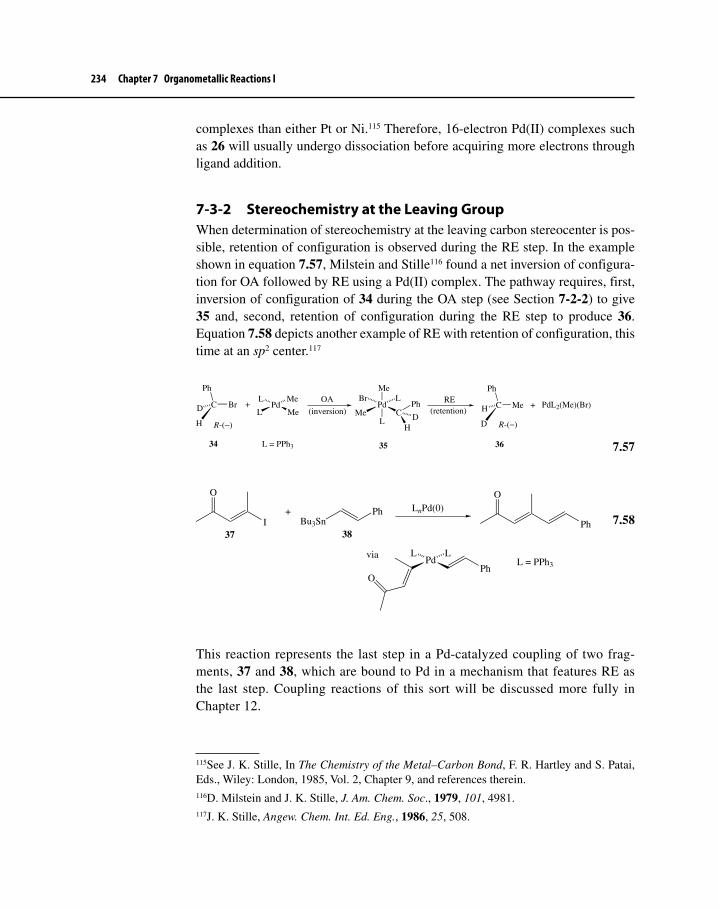
234 Chapter 7 Organometallic Reactions I
complexes than either Pt or Ni.115 Therefore, 16-electron Pd(II) complexes such as 26 will usually undergo dissociation before acquiring more electrons through ligand addition.
7-3-2 Stereochemistry at the Leaving GroupWhen determination of stereochemistry at the leaving carbon stereocenter is pos-sible, retention of configuration is observed during the RE step. In the example shown in equation 7.57, Milstein and Stille116 found a net inversion of configura-tion for OA followed by RE using a Pd(II) complex. The pathway requires, first, inversion of configuration of 34 during the OA step (see Section 7-2-2) to give 35 and, second, retention of configuration during the RE step to produce 36. Equation 7.58 depicts another example of RE with retention of configuration, this time at an sp2 center.117
C
Ph
Br
H
D PdL
L Me
Me+ Pd
Me
Br L
C
Me
L
Ph
DH
C
Ph
Me
D
H + PdL2(Me)(Br)
R-(−) R-(−)
OA
(inversion)RE
(retention)
34 35 36L = PPh3
7.57
I
O
+Bu3Sn
Ph LnPd(0)
Ph
O
37 38
via PdL L
OPh
L = PPh3
7.58
This reaction represents the last step in a Pd-catalyzed coupling of two frag-ments, 37 and 38, which are bound to Pd in a mechanism that features RE as the last step. Coupling reactions of this sort will be discussed more fully in Chapter 12.
115See J. K. Stille, In The Chemistry of the Metal–Carbon Bond, F. R. Hartley and S. Patai, Eds., Wiley: London, 1985, Vol. 2, Chapter 9, and references therein.116D. Milstein and J. K. Stille, J. Am. Chem. Soc., 1979, 101, 4981.117J. K. Stille, Angew. Chem. Int. Ed. Eng., 1986, 25, 508.

7-3 Reductive Elimination 235
7-3-3 C–H EliminationExamples of elimination of C−H are increasingly cited in the literature, and investigations of C−H RE elimination are used to help elucidate pathways of C−H bond activation, taking advantage of the principle of microscopic revers-ibility. Research with d8 rhodium and iridium complexes118 indicates that RE in these cases is concerted, intramolecular, and involves the loss of carbon and hydrogen that have a cis relationship to each other. In these cases, the now-familiar rate-determining loss of phosphine ligand (mechanism 1) occurs before a new C−H bond can form. In a simple way, we can view the loss of phosphine as both effectively reducing electron density at the metal (thus forcing the need for lowering the oxidation state through RE) and providing a less stable stereochemical configuration. RE of this unstable configuration is thus energetically favorable. Equations 7.59 and 7.60 provide two examples of C−H elimination.
RhL3Cl + RCHO RhCl
L C
L
H
L
R
OL
RhCl
L C
L
H
R
O
RhCl
L C
L
H
R
OA RhL2(CO)(Cl)
+ R−HL = PMe3 39 40 41
REO
7.59
RhCl
Me3P
PMe3
H
PMe3
CH3
O
Rh(PMe3)3Cl +H−CH2 CH3
O
7.60
As shown in equation 7.59, OA of the aldehyde yields the cis- hydridoacylrhodium complex, 39. Heating results in ligand dissociation to give 40, which undergoes migratory deinsertion (to be discussed in Chapter 8) to produce 41. Isomerization of 41 to a cis-hydridoalkyl complex presumably occurs before final the final RE step to yield the C−H elimination product. These reactions have applications in catalytic industrial process known as olefin hydroformylation (Section 9-2). Equation 7.60 illustrates straightforward RE to form a new C−H bond.
118D. Milstein, Acc. Chem. Res., 1984, 17, 223.

236 Chapter 7 Organometallic Reactions I
The timing of the breakage of the M−C and M−H bonds and the forma-tion of the C−H bond is of interest to chemists. Equation 7.61119 illustrates the commonly accepted and now-familiar pathway for RE to form C−H bonds, which first involves a three-centered transition state, followed by an η2–C−H metal complex 42 and finally production of the free alkane and reduced metal.
LnM
R
H
LnMR
HLnM
R
HLnM +
R
H
42
7.61
7-3-4 Dinuclear Reductive EliminationsRE is also possible when two complexes react according to equation 7.62.
M′−X + M−Y M′−M + X−Y 7.62
One well-known example (equation 7.63) involves the formation of dihydrogen from the reaction of two equivalents of HCo(CO)4. A radical mechanism appears to be operative in this case involving hydrogen atom transfer.120
2 HCo(CO)4 H2 + Co2(CO)8 7.63
Several other examples of this type of elimination have been discovered and a variety of mechanisms postulated. It is beyond the scope of this book to provide a
119For a discussion with extensive references of C−H bond formation involving reductive elimination of alkanes, see W. D. Jones, A. J. Vetter, D. D. Wick, and T. O. Northcutt, “Alkane Complexes as Intermediates in C−H Bond Activation Reactions,” In Activation and Functionalization of C–H Bonds, K. I. Goldberg and A. S. Goldman, Eds., ACS Symposium Series 885, American Chemical Society: Washington, D. C., 2004, pp. 56–69. See also another chapter in the same volume: “Kinetic and Equilibrium Deuterium Isotope Effects of C−H Bond Reductive Elimination and Oxidative Addition Reactions Involving the Ansa-Tungstenocene Methyl-Hydride Complex [Me2Si(C5Me4)2]W(Me)H,” pp. 86–104.120H. W. Sternberg, I. Wender, R. A. Friedel, and M. Orchin, J. Am. Chem. Soc., 1953, 75, 2717.
Exercise 7-9 Propose a mechanism for the conversion of 41 to RhL2(CO)Cl in equation 7.59. [Hint: Consider a mechanism involving loss of L to produce five-coordinate intermediates followed by addition of L.]

Suggested Reading 237
detailed investigation of these reactions, but the reader should be aware that they do occur.121
Suggested Reading
Trans Influence and trans EffectF. R. Hartley, Chem. Soc. Rev., 1973, 2, 163.F. Basolo and R. G. Pearson, “The Trans Effect in Metal Complexes,” Prog. Inorg.
Chem., 1962, 4, 381–453.
Associative Substitution on 18-Electron ComplexesF. Basolo, New J. Chem., 1994, 18, 19.J. M. O’Connor and C. P. Casey, Chem. Rev., 1987, 87, 307.F. Basolo, Inorg. Chim. Acta., 1985, 100, 33.
17- and 19-Electron ComplexesS. Sun and D. A. Sweigert, Adv. Organomet. Chem., 1996, 40, 171.
Oxidative Addition and Reductive EliminationF. Ozawa, “Reductive Elimination,” In Fundamentals of Molecular Catalysis, H. Kurosawa
and A. Yamamoto, Eds., Elsevier: Amsterdam, 2003, pp. 479–512.J. K. Stille, “Oxidative Addition and Reductive Elimination,” In The Chemistry of the
Metal–Carbon Bond, F. R. Hartley and S. Patai, Eds., Wiley: New York, 1985, Vol. 2, pp. 625–787.
C–H and C–C Bond ActivationK. I. Goldberg and A. S. Goldman, Eds., Activation and Functionalization of C–H Bonds,
ACS Symposium Series 885, American Chemical Society: Washington, D. C., 2004.
R. H. Crabtree and D.-H. Lee, “Activation of Substrates with Non-Polar Single Bonds,” In Fundamentals of Molecular Catalysis, H. Kurosawa and A. Yamamoto, Eds., Elsevier: Amsterdam, 2003, pp. 65–113.
J. A. Labinger and J. E. Bercaw, Nature, 2002, 417, 507.S. Murai, Ed., Activation of Unreactive Bonds and Organic Synthesis (Vol. 3 in
the Topics in Organometallic Chemistry series), Springer-Verlag: Heidelberg, 1999.
121For a review of dinuclear REs, see J. P. Collman, L. S. Hegedus, J. R. Norton, and R. G. Finke, Principles and Applications of Organotransition Metal Chemistry, University Science Books: Mill Valley, CA, 1987, pp. 333–343.

238 Chapter 7 Organometallic Reactions I
Problems7-1 Structure 1 below underwent ligand exchange with CO to give only
mer-2, which later rearranged to fac-2. Treatment of 1 with P(CD3)3 gave 3, showing that ligand exchange occurred only trans to the SiMe3 group. An X-ray analysis of 1 indicated that other than the length of the Ru−P bond located trans to H, the next longest Ru−P bond was situated trans to the SiMe3 group.122
RuL
L SiMe3
H
L
L
+ CO RuC
L SiMe3
H
L
L
RuL
L SiMe3
H
C
L
L
L = PMe31 mer-2 fac-2
P(CD3)3
Ru(CD3)3P
L SiMe3
H
L
L
3
O
O
a. How do the trans effect and trans influence of the SiMe3 group com-pare with those of phosphines? Explain?
b. What is the driving force for the rearrangement of mer-2 to fac-2?
7-2 Consider the data shown in the table on the next page. What do these data tell you about the relative trans influence of the σ carbon donor ligands (CH3–nRn) listed? What is the reason for the trend?123
PtH3C
Ph2P PPh2
CH3−nRn
JPt−P (trans)
122V. K. Dioumaev, L. J. Procopio, P. J. Carroll, and D. H. Berry, J. Am. Chem. Soc., 2003, 125, 8043.123T. G. Appleton and M. A. Bennett, Inorg. Chem., 1978, 17, 738.

Problems 239
Ligand n JPt-P (trans)
CH3 0 1794 Hz CH2(COCH3) 1 2346 Hz CH(COCH3)2 2 2948 Hz C(COCH3)3 3 4124 Hz
7-3 A ligand substitution reaction, LnML1 + L2 LnML2 + L1, has the rate law rate = k[LnML1][L2] + k′ [LnML1].
What does this rate law imply about the mechanism of this reaction?7-4 The rates of exchange of CO (labeled with 13C) on cis-[M(CO)2X2]–
complexes—where M = Rh, Ir and X = Cl, Br, I—have been measured, and the results are given in the table below.124
MX
X C
C+ 2 *CO M
X
X *C
*C+ 2 CO
* = 13C
O
O
O
O
a. What do the data suggest about the mechanistic pathway for CO exchange?
b. Why does the rate of exchange increase going from Cl to I?c. Why is the exchange rate faster for Rh complexes compared with Ir?
7-5 In a series of experiments, the rate of phosphine dissociation from cis-Mo(CO)4L2 (L = phosphine) was determined for several phosphines. The overall reaction in each case was of the form
cis-Mo(CO)4L2 + CO Mo(CO)5L + L.
124R. Churlaud, U. Frey, F. Metz, and A. E. Merbach, Inorg. Chem., 2000, 39, 304.
M X k (L/mol-s at 298 K)
∆H‡ ∆S‡ (eu) ∆V‡
(cm3/mol)
Ir Cl 1100 3.7 –32 –21
Br 13,000 3.2 –29
I 99,000 3.0 –26
Rh Cl 1700 4.2 –30 –17
Br 30,000 2.7 –29
I 850,000 2.4 –23

240 Chapter 7 Organometallic Reactions I
Rate data: Phosphine Rate constant (s–1)
PMe2Ph < 1.0 × 10⁻⁶
PMePh2 1.3 × 10⁻⁵
PPh3 3.2 × 10⁻³
Account for this trend in reaction rates. 7-6 Verify the rate law shown below and expressed in Section 7-1-4, relating
to Scheme 7.2.
Rate = k1k2[M(CO)4diene][L]/(k–1 + k2[L]) + k3[M(CO)4diene][L]
Also verify that when k2[L] is large, the rate law reduces to
Rate = k1[M(CO)4diene] + k3[M(CO)4diene][L].
7-7 When PEt3 reacts with Mo(CO)6 the final product is fac-Mo(CO)3
(PEt3)3. Substitution goes no farther than trisubstitution. Give two reasons why this might be so. Account for the stereochemistry of the product. [Hint: Why would production of the mer-isomer be not as likely?]
7-8 The chiral Mn complex below undergoes racemization according to the equation shown.
MnPPh3
Ph NO
OPhMe/25 oC
t1/2 = 21 min.Rate ∝ 1/[PPh3]
MnPPh3
Ph NO
O MnPh3P
NO
+
Ph
O
Propose a mechanism that is consistent with the rate being affected inversely by the concentration of PPh3.
7-9 The reaction below shows a rate law that is second order in substrate metal complex and first order in phosphine. The ∆S‡ is negative, and an intermediate was isolated and shown to be (PPh3)(CO)4Mn(NO). Propose a mechanism for the reaction. What is the nature of the bonding of the NO ligand at each stage of the reaction?
(CO)4Mn(NO) + PPh3 (PPh3)(CO)3Mn(NO)
7-10 Consider the reactions shown on the next page (M = Nb, Ta).

Problems 241
M CC
CC
M CC
CC
M CC
PBu3C
M CC
PBu3C
PBu3
PBu3
+ CO
+ CO
O
OO
O O
O
O
O
O
OO
OO
O
Regardless of the π ligand, the Nb complexes underwent ligand exchange over two times faster than the comparable Ta complex. The sign of the entropy of activation for ligand exchange was positive or slightly negative for the Nb– and Ta–Cp complexes, but highly negative for either indenyl (Ind) complex. Moreover, rates of ligand exchange were generally faster for the indenyl complexes than for the Cp complexes.125
Propose mechanistic pathways for ligand exchange that account for the differences in rate between Cp–M and Ind–M complexes.
7-11 Assign the oxidation states and valence electron counts for the transition metals in the following complexes:
a. Ir(CO)(PPh3)2Clb. (η5–C5H5)2TaH3
c. [Rh(CO)2I2]–
d. (η5–C5H5)(CH3)Fe(CO)2
e. CH3C(=O)Co(CO)3
7-12 Assign the oxidation states and valence electron counts for the transition metals in the following complexes:
a. The reactant and product in equation 7.29b. Structure 8 in Scheme 7.6c. Structure 31 in Figure 7.12d. Structure 33 and its reaction product in equation 7.56
125T. E. Bitterwolf, D. Lukmanova, S. Gallagher, A. L. Rheingold, I. A. Guzei, and L. Liable-Sands, J. Organomet. Chem., 2000, 605, 168.

242 Chapter 7 Organometallic Reactions I
7-13 Propose a stepwise mechanism for the formation of compounds 4 and 5.126
WNH
PPh2
XS PMe3
45 oC/4 hoursW
NPPh3
Me3P
WNH
PMe3
Ph2P
+
4 5
O O O
7-14 Shilov and co-workers were among the first to demonstrate intermolecu-lar C−H bond activation. Consider the reaction of CH4 to give CH3OH, which is stoichiometric in the Pt(IV) complex and catalytic in the Pt(II) complex.127
Such a reaction could be quite useful on an industrial scale, but unfor-tunately, it is stoichiometric in highly expensive Pt complex. Since its discovery in 1972, Shilov chemistry has been the focus of numerous investigations, many of which have sought to replace the Pt(IV) stoichio-metric oxidant with a cheaper alternative. In the course of this research, the mechanism of the Shilov C−H bond activation has been elucidated. The following scheme shows the catalytic cycle involved.
CH4 + PtCl62− H2O
PtCl42− (cat.)
H2O/120 oCCH3OH + PtCl4
2− + 2 HCl
Pt(II)
ClCH4
HCl
Pt(IV)Cl
2−
Pt(II)
CH3
2−CH3
Cl
2−
PtCl42− PtCl6
2−
HCl + CH3OH
H2O
(PtCl42−)
126D. J. Burkey, J. D. Debad, and P. Legzdins, J. Am. Chem. Soc., 1997, 119, 1139.127N. F. Gol’dshleger, V. V. Es’kova, A. E. Shilov, and A. A. Shteinman, Zhurnal Fizicheskoi Khimii, 1972, 46, 1353.

Problems 243
For each of the three steps, supply mechanistic detail that describes how the transformation occurs.
7-15 Supply mechanistic details for each of the steps involved in the reaction scheme shown below, which exemplifies the use of pincer ligands:128
CH3
Me
Me
PPh2
PPh2
Me
Me
PPh2
PPh2
Rh PPh3 Rh
Me
Me
PPh2
PPh2
PPh3
H
Me
Me
PPh2
PPh2
HRh(PPh3)4
3 PPh3 + H2
H2
CH4
PMe3 (XS)
HRh(PPh3)4
3 PPh3 + H2
HRh(PMe3)4
+ H2
128M. Gozin, A. Weisman, Y. Ben-David, and D. Milstein, Nature, 1993, 364, 699.

Once a ligand is attached to a metal, several events may occur. In Chapter 8 we will consider a few of the most common possibilities for reactions involving changes in the ligand. Such transformations are often integral parts of the catalytic cycles we will examine in Chapter 9. Reactions on ligands bound to a transition metal are also of great interest to the organic chemist, because transformations are now possible that would be difficult or impossible to do using conventional carbon-based chemistry. We will explore the basis for these new possibilities in Chapter 8, and then apply what we learn in Chapters 9, 10, 11, and 12. We will divide our discussion into two major parts: (1) insertion or deinsertion of a ligand with respect to a bond between a metal and another ligand and (2) attack on a ligand by a nucleophile or electrophile.
8-1 INSERTION AND DEINSERTIONEquations 8.1 and 8.2 describe the general process of insertion of a ligand into an M−Y bond. The former shows a process known as 1,1-insertion and the latter its 1,2 counterpart. The reverse reactions are known interchangeably as deinsertion, extrusion, or elimination.
Y
LnM X Z1
LnM X Y1
Z
1,1-Insertion
2
2
8.1
Organometallic Reactions IIReactions Involving Modi� cation of Ligands
EIGHT
244

8-1 Insertion and Deinsertion 245
Y
LnM
1
Z
X
2
1,2-Insertion
LnM X Z Y1 2
8.2
8-1-1 1,1-Insertion: “Carbonyl Insertion” (Alkyl Migration) ReactionsPerhaps the most well-studied example of the insertion–deinsertion reaction is that of the 1,1-insertion of carbon monoxide into a metal–alkyl (or aryl) bond. This reaction figures prominently as a key step in a number of catalytic processes. The numbering designation of 1,1 refers to the numbering on the CO ligand. If we designate the carbon of the CO ligand to be the 1-position, the insertion occurs such that both the metal and the original alkyl ligand are bonded to that carbon when insertion is complete, hence the numbers 1,1. Equation 8.3 illustrates inser-tion of a carbonyl ligand into a Pd−C bond, one of the reactions shown earlier in Scheme 7.7.
Pd Br
PPh3
PPh3
C
Ph
H
RCO
(Retention ofconfiguration)
Pd Br
PPh3
PPh3
C
Ph
H
R C
O
8.3
The prototypical example of carbonyl insertion, and the one most thoroughly investigated, involves reaction of CO with (CH3)Mn(CO)5 to yield the acetyl manganese complex, which is shown in equation 8.4.
CH3 Mn(CO)5 + CO CH3 C Mn(CO)5
O
8.4
From the net equation we might expect that the CO inserts directly into the Mn–CH 3 bond; if such were the case, the label “CO insertion” would be entirely appropriate for this reaction. Other mechanisms, however, are possible that would give the overall reaction stoichiometry while involving steps other than insertion of an incoming CO. The following three mechanisms have been suggested as plausible for this reaction.
Mechanism 1: CO insertionDirect insertion of CO into metal–carbon bond.

246 Chapter 8 Organometallic Reactions II
Figure 8-1Possible Mechanisms for CO Insertion Reactions
MnC
C
C
C
CH3OC MnC
C
C
C
COC
MnC
C
C
C
CH3OC
MnC
C
C
C
CH3OC
CH3
O
+ CO
Intermolecular, direct insertion
IntramolecularCO insertion
IntramolecularCH3 migration
MnC
CC
COC CH3
O
COMn
C
C
C
C
COC CH3
O
Mechanism 1:
Mechanism 2:
Mechanism 3:
MnC
C
C
C
OC
CH3
O
+ CO MnC
C
C
C
OC
CH3
O
CO
O
O
O
O
O
O
O O O
O
O
OO
O
OO
O
O
O O
O
O
O
O
O
O
O
O
O
O
C CH3New CO cis to
O
C CH3New CO cis to
Mechanism 2: CO migrationMigration of CO to give intramolecular CO insertion. This would give rise to a 5-coordinate intermediate, with a vacant site available for attachment of an incoming CO.
Mechanism 3: Alkyl migrationIn this case the alkyl group would migrate—rather than the CO—and attach itself to a CO cis to the alkyl. This would also give a 5-coordinate interme-diate with a vacant site available for an incoming CO.
These mechanisms are described schematically in Figure 8-1. In both mecha-nisms 2 and 3, the intramolecular migration is considered most likely to occur to the migrating group’s nearest neighbors, located in cis positions.

8-1 Insertion and Deinsertion 247
Experimental evidence that may be applied to evaluating these mechanisms includes the following.1
I. Reaction of CH3Mn(CO)5 with 13CO yields a product with the labeled CO in carbonyl ligands only—none is found in the acyl [CH3C(=O)] position.
II. When the reverse reaction (which occurs readily on heating CH3C(=O)Mn(CO)5) is carried out with 13C in the acyl position, the CH3Mn(CO)5 formed has the labeled CO entirely cis to CH3. No labeled CO is lost in this reaction.
CH3 Mn(C*O)(CO)4 + COCH3 C*
Mn(CO)5
O
∆
* = 13C
III. When the reverse reaction is carried out with a 13CO positioned cis to the acyl group, the product has a 2:1 ratio of cis to trans (cis and trans refer-ring to the position of labeled CO relative to CH3 in the product). Some labeled CO is also lost in this reaction.
The mechanisms can now be evaluated on the basis of these data. First, mechanism 1 is definitely ruled out by experiment I. Direct insertion of 13C must result in 13C in the acyl ligand; since none is found, the mechanism cannot be a direct insertion. Mechanisms 2 and 3, on the other hand, are both compatible with the results of this experiment.
The principle of microscopic reversibility (discussed in Chapter 7) is applicable when considering the information uncovered by experiment II. Let us assume that the acyl manganese complex contains a 13C-labeled carbonyl carbon (Figure 8-2). If the forward reaction is carbonyl migration (mechanism 2), the reverse reaction must proceed by loss of a CO ligand attached directly to the metal, resulting in an empty site, followed by migration of 13CO from the acyl ligand to the empty site. Because this migration is unlikely to occur to a trans position, all of the product should show a 13CO in a cis position relative to the alkyl ligand. If the mechanism is alkyl migration (mechanism 3), the reverse reaction must proceed by loss of a CO ligand attached directly to the metal, again providing an empty site, followed by migration of the alkyl portion of the acyl ligand to the vacant site. Because migration of an alkyl group to a trans position is also unlikely, all of the product should again show the 13CO situated cis to the alkyl group. Since both mechanisms
1T. C. Flood, J. E. Jensen, and J. A. Stadler, J. Am. Chem. Soc., 1981, 103, 4410, and references cited therein.

248 Chapter 8 Organometallic Reactions II
Figure 8-2Mechanisms of Reverse Reactions for CO Migration and Alkyl Migration Related to Experiment II
Mechanism 2 vs. Mechanism 3:
MnC
C
C
C
COC CH3
O
* MnC
CC
COC CH3
O
* MnC
C
C
CH3OC
*
cis
CO Migration
Mechanism 2:
MnC
C
C
C
COC CH3
O
* MnC
CCOC CH3
O
* MnC
C
CH3
C
COOC
cis
CH3 Migration
Mechanism 3:
*
O
O OCO
O
O
OCO O
O
O
O
O
O
O
O
O
O
O
O
O
MnC
C
C
CH3OCMnC
C
C
C
COC CH3
O
+ CO*
*
∆
100% cis
O
OCO
O
O
O
O
O
2 and 3 in effect transfer labeled CO in the acyl group to a cis position, they are consistent with the experimental data for experiment II.
The third experiment (Figure 8-3), which also invokes the principle of micro-scopic reversibility, allows a choice between mechanisms 2 and 3. The CO migra-tion of mechanism 2, starting with 13CO cis to the acyl ligand, requires migration of CO from the acyl ligand to the vacant site. As a result, 25% of the product should have no 13CO label, and 75% should have the labeled CO cis to the alkyl, as shown in Figure 8-3. On the other hand, alkyl migration (mechanism 3) should yield 25% with no label, 50% with the label cis to the alkyl, and 25% with the label trans to the alkyl. Because this is the ratio of cis- to trans-products found
Exercise 8-1 Show that heating of CH313C(=O)–Mn(CO)5 would not be expected to
yield the cis product by mechanism 1.

8-1 Insertion and Deinsertion 249
Figure 8-3Mechanisms of Reverse Reactions for CO Migration and Alkyl Migration Related to Experiment III
MnC
C
C
C
COC CH3
O
*12
34
MnC
C
C
C
COC CH3
O
*12
34
Mn C CH3
O
Mn C CH3
O
Mn C CH3
O
Mn C CH3
O
Mn CH3
Mn CH3
*
Mn CH3
*
Mn CH3
*
loss of 1
loss of 2
loss of 3
loss of 4
*
*
*
no *CO
cis
cis
cis
Mn C CH3
O
Mn C CH3
O
Mn C CH3
O
Mn C CH3
O
Mn
CH3
MnCH3
*
Mn
CH3
*
MnH3C
*
loss of 1
loss of 2
loss of 3
loss of 4
*
*
*
no *CO
cis
trans
cis
Mechanism 2:
Mechanism 3:
* :
:
C-13 labeled CO
unlabeled CO
O
O
O
O
O
O
O
O
in the experiment, the evidence supports mechanism 3, which continues to be the accepted pathway for this reaction.
One additional point about the mechanism of these reactions should be made. In the discussion of mechanisms 2 and 3 above, it was assumed that the intermediate was a square pyramid and that no rearrangement to other geom-etries (such as trigonal bipyramidal) occurred. Other labeling studies, involving reactions of labeled CH3Mn(CO)5 with phosphines, have supported a square–pyramidal intermediate.2
2See Footnote 1.

250 Chapter 8 Organometallic Reactions II
Stereochemical probes can provide useful information about the course of a reaction (see Section 7-2-3). Reaction of the threo iron complex (equation 8.5) with PPh3 resulted in the threo migratory insertion product (95% stereoselectiv-ity), which indicates that the alkyl group migrated with retention of configura-tion of the migrating center.3 This stereochemical result is consistent with that observed for alkyl migrations to carbocationic centers in organic reactions.
D H
C(CH3)3
HD
CpFe(CO)2
PPh3
C
D H
C(CH3)3
HD
CpFe(CO)(PPh3)
O
8.5
If CO insertion is really alkyl migration to CO, then the configuration of the metal center should not be retained upon migration when all ligands to the metal are different. In the CH 3Mn(CO)5 complexes studied, it is impossible to tell that the configuration at the metal center changed after alkyl migration and attachment of free CO to the metal. The pseudotetrahedral iron complex shown in Scheme 8.14 could serve as a useful stereochemical probe for examining the mechanism of carbonyl insertion–deinsertion.5 If the alkyl group migrates, we would expect 1 to form. If, on the other hand, the CO group migrates, enantiomeric complex 2 should be produced. Note that formation of 1 requires inversion of configuration at the metal, whereas 2 exhibits retention at the iron center. When the reaction was run in nitroethane solvent, 1 formed with 95% ee;6 however, when coordinating solvents such as hexamethylphosphoramide (HMPA) and acetonitrile were used,
3G. M. Whitesides and D. J. Boschetto, J. Am. Chem. Soc., 1969, 91, 4313 and P. L. Bock, D. J. Boschetto, J. R. Rasmussen, J. P. Demers, and G. M. Whitesides, J. Am. Chem. Soc., 1974, 96, 2814.4A comment on notation is in order here. A box (□) attached to a metal signifies an open coordination site available for ligand coordination.5T. C. Flood, Top. Stereochem., 1981, 12, 37.6The term “ee” stands for enantiomeric excess, that is the excess of one enantiomer over the other (%R – %S). For example, if a synthesis produced 90% S and 10% R, the ee = 90% – 10% = 80%. This means that the mixture consists of 80% S and 20% racemic modification (R + S). In the example used above, ee = 95% indicates the mixture consists of 97.5% S and 2.5% R.
Exercise 8-2 Predict the product distribution for the reaction of cis-CH3Mn(CO)4
(13CO) with PR3 (R = C2H5) (You may check your answer by consulting Footnote 1).

8-1 Insertion and Deinsertion 251
both 1 and 2 formed. In the latter cases, there was even an excess of product 2 observed compared with 1.7 It appears, unfortunately, that experiments designed to test the stereochemistry of the metal upon alkyl migration have produced con-flicting results (see also problem 8-3). Whether the experiments shown in Scheme 8.1 are the result of alkyl migration in nitroethane and net CO migration using coordinating solvents is unclear. It is also possible under some reaction conditions that the configuration of the intermediate upon alkyl migration is not fixed, thus leading to both inversion and retention of configuration at the metal center.
Other ConsiderationsWithin groups of transition metals, the tendency for CO insertion usually has the following order of reactivity: row 3 ~ row 4 > row 5.8 This trend reflects the strength of the M−C bond, which tends to increase as one goes down a column of the periodic table. Such results again lend support to the mechanism of insertion consisting of alkyl rather than CO migration. The observation that CO insertion into M−H bonds is less facile than insertion into M−C bonds also seems to reflect the typically higher bond strength of M−H bonds compared with M−C.
The presence of Lewis acids enhances CO insertion, not only by increasing the overall rate of reaction, but also by causing an alternative pathway of insertion to occur. The role of the Lewis acid is to complex with a CO ligand (thus making
7T. C. Flood and K. D. Campbell, J. Am. Chem. Soc., 1984, 106, 2853.8See, for example, M. Aubert, G. Bellachioma, G. Cardaci, A. Macchioni, G. Reichenbach, and M. C. Burla, J. Chem. Soc. Dalton Trans., 1997, 1759.
Scheme 8.1Investigations of Carbonyl Insertion on Chiral Iron Complexes
Fe
C
Ph3P Et
Et migrates
CO migrates
Fe
C
Ph3P
EtO
Fe
C
Ph3P C
EtO
CO
FePh3P C
Et
O Fe
C
Ph3P C
Et
OCO
1
2
Inversion at Fe
Retention at Fe
O
O
O

252 Chapter 8 Organometallic Reactions II
the carbonyl carbon more positive and more susceptible to attack by the relatively electron-rich alkyl group) and to stabilize the resulting unsaturated acyl complex after alkyl migration. Equation 8.6 shows a specific example of the role of AlBr3 in promoting CO insertion in alkyl metal carbonyl complexes, which actually occurs in the absence of free CO.9
MnC
C
C
C
CH3OCAlBr3
MnC
C
C
C
BrOC
H3CO
AlBr2
O
O
O
OO
O
O
8.6
More recently, there have been several investigations of CO insertion using high-level molecular orbital calculations at the DFT level. These have confirmed that CO insertion is indeed alkyl migration, and two intermediates, structures 3 and 4, have been shown to exist along the reaction path.10
Mn
C
C
C
COCCH3
O
3
O
OO
Mn
C
C
C
C
OC
O
C
H
H
H
4
O
O
O
Structure 3 is termed a coordinatively-saturated η2-complex with the carbonyl oxy-gen also bonding to the metal. Such complexes are especially important during CO insertion with early transition metal complexes, since the metals involved tend to be highly oxophilic.11 The η2-complex has also been detected during photochemically induced deinsertion of CO in CH3Mn(CO)5.12 Structure 4 is a coordinatively unsaturated complex that contains an agostic bond between the metal and the C−H hydrogen. Such interaction produces stabilization of the empty site.
It now seems clear that a reaction that initially appears to involve CO inser-tion, and is often so designated, does not involve CO insertion at all! In fact, it
9S. B. Butts, S. H. Strauss, E. M. Holt, R. E. Stimson, N. W. Alcock, and D. F. Shriver, J. Am. Chem. Soc., 1980, 102, 5093 and T. G. Richmond, F. Basolo, and D. F. Shriver, Inorg. Chem., 1982, 21, 1272.10A. Derecskei-Kovacs and D. S. Marynick, J. Am. Chem. Soc., 2000, 122, 2078 and X. Wang and E. Weitz, J. Organomet. Chem., 2004, 689, 2354.11Oxophilicity is a measure of the affinity of a metal for bonding with oxygen.12P. C. Ford and S. Massick, Coord. Chem. Rev., 2002, 226, 39 and S. M. Massick, V. Mertens, J. Marhenke, and P. C. Ford, Inorg. Chem., 2002, 41, 3553.

8-1 Insertion and Deinsertion 253
is really analogous to a 1,2-alkyl shift in organic chemistry where a relatively electron-rich alkyl carbon migrates (with retention of configuration) to a rela-tively electron-poor center in order to produce a more stable carbocation. It is not uncommon for reactions, on close study, to be found to differ substantially from how they might first appear. In this reaction, as in all chemical reactions, it is extremely important for chemists to undertake mechanistic studies and to keep an open mind with regard to possible alternative mechanisms. No mechanism can be proven; it is always possible to suggest alternatives consistent with the known data. It does appear, however, that for the vast majority of carbonyl insertions, the reaction involves migration of the alkyl group to the carbonyl ligand with reten-tion of configuration of the migrating center.
8-1-2 1,2-Insertion and Deinsertion (β-Elimination)1,2-Insertion into M–H BondsAlkenes and alkynes can undergo 1,2-insertion into M–H bonds. The numbering again refers to the numbers for the carbon atoms on the double or triple bond. A schematic insertion reaction is outlined below:
H
LnM1
C
C
2LnM C C H
1 2
H
LnM1
C
C
2LnM C C H
1 2
or
Complex A [ν(CO) = 1670 cm–1] rearranges cleanly to the isomeric compound B [ν(CO) = 2040 cm–1] at 30o in benzene. Draw a possible structure for B.
Ir
PhO
Cl PPh3
ClPh3P
A
Exercise 8-3

254 Chapter 8 Organometallic Reactions II
We can also think of 1,2-insertion as migration of the hydride to the β-position on the alkene or alkyne, much the same as we saw for 1,1-CO migratory insertion.
A useful 1,2-insertion reaction encountered in organic chemistry is hydrobo-ration of an alkene to form an alkylborane (equation 8.7), which subsequently undergoes treatment with alkaline H2O2 to yield an alcohol.
C CMe
Me H−BH2C C
BH2H
Me H
HMe
H2O2
OH− C C
OHH
Me H
HMeH
H
8.7
From the organic chemist’s standpoint, hydroboration is considered a syn addi-tion of a B−H bond across a C=C or C≡C bond. Categorizing the reaction as a 1,2-insertion is, however, equally valid.
We saw in Chapter 6 that a reaction that is the reverse of 1,2-insertion—called 1,2- or β-elimination—may also occur with metal alkyls, the product of insertion.13 Equation 8.8 details the insertion–elimination reaction that yields a vacant site for coordination in the forward direction (1,2-insertion) and requires a vacant site for the reverse (β-elimination) pathway.
LnM H
H2C CH2 H2C CH2
LnM H
H2C CH2
LnM HLnM CH2−CH3
α β
Insertion
β-Elimination
8.8
Experimental evidence and computational analysis point to a mechanism in which the alkene (or alkyne) carbons and the M–H bond must be nearly coplanar to react. Once the metal alkene complex has achieved such geometry, 1,2-insertion can occur. During insertion, the reactant proceeds through a four-center transition state.14 The reaction involves simultaneous breakage of the M−H and C−C π bonds, as well as the formation of an M−C σ bond and a C−H bond at the 2- position of the alkene (or alkyne). The result is a linear compound, LnM(CH2CH3), in the case of ethene insertion. The reverse reaction, β-elimination, follows the same pathway starting from a metal–alkyl complex with an open coordination site.
13The Greek letter α is used to designate the carbon atom (or other non-hydrogen atom) directly attached to the metal. The next position beyond the α-position is designated β and the next one beyond that γ, etc.14See H. Wadepohl, U. Kohl, M. Bittner, and H. Köppel, Organometallics, 2005, 24, 2097, for a recent computational study at the DFT level of the mechanism of C=C insertion into a Co–H bond, which shows a picture of the four-centered transition state determined by high-level MO calculations.

8-1 Insertion and Deinsertion 255
Note that the hapticity of the organic ligand decreases by one (η2 to η1) with insertion and increases by one (η1 to η2) during β-elimination.
Insertion is generally exothermic (but not highly so) according to the following analysis using the estimated energies of bonds made and broken (see Table 7-6) in the schematic equation 8.9.
H
M+ C C M C C H
8.9
Bond Energies:
Broken: Formed:
M–H: 65–80 kcal/mol M–C: 40–70 kcal/mol π-C=C: 50–60 kcal/mol C–H: 90–100 kcal/mol
Total: 115–140 kcal/mol Total: 130–170 kcal/mol
∆rH = –15 to –30 kcal/mol
Because ∆rS for insertion should be negative, the free energy of the reac-tion will be slightly negative. This, of course, means that the reverse reaction (β-elimination) should also have a ∆rG value that is slightly positive, since the positive ∆rS counterbalances the positive ∆rH. On the basis of thermodynamics, it is thus not surprising that both insertion and deinsertion are common compo-nents of catalytic cycles because the free energy barrier of either reaction is not insurmountable. Experiment and theory15 have demonstrated that 1,2-insertion tends to be more uphill thermodynamically as one goes from third-row to fifth-row transition metal complexes, probably due mainly to increasing M–H bond strength.
Transition metal alkyl complexes tend to be kinetically unstable and rapidly undergo β-elimination. Equation 8.10 shows the decomposition of a dibutylplati-num complex, first through β-elimination and then through the already-familiar mode of reductive elimination.
PtPh3P
Ph3P
β-eliminationPt
Ph3P
Ph3P
H+
αβ
β
α
RE+ (PPh3)2Pt
8.10
15Y. Han, L. Deng, and T. Ziegler, J. Am. Chem. Soc., 1997, 119, 5939, and references therein.

256 Chapter 8 Organometallic Reactions II
There are several ways to prevent or at least lessen the propensity for β-elimination to occur (especially after 1,2-insertion has occurred). Obviously, if there is no β-hydrogen atom, elimination cannot occur. Electron withdrawing atoms, such as fluorine, placed at the α- or β-alkyl positions (equation 8.11), will also lessen the tendency for β-elimination by strengthening the M−C σ bond.
RhPh3P
Ph3P C
H+ F2C=CF2 Rh
Ph3P
Ph3P
CF2α
βCF2
H
+ CO
1,2-Insertion
β-Elimination
O
8.11
Coordinatively-saturated metal–alkyl complexes tend not to undergo β-elimination, especially if they are in solution in the presence of an excess of L-type ligand, such as CO or PR3, or if ligands also bound to the complex, such as Cp or bidentate phosphines, are reluctant to leave and provide an open coor-dination site.
Metal alkyls in which the metal, C–C bond, and the β-hydrogen cannot become coplanar either do not undergo elimination or do so at a severely retarded rate. For example, the platinacyclopentane16 (5) is kinetically more stable than the corresponding dibutyl complex by a factor of 104.
PtPh3P
Ph3PPt
Ph3P
Ph3P
5
Equation 8.12 illustrates β-elimination from a rhodium complex, a reaction preceded by deinsertion of CO. The reaction is significant in demonstrating that the stereochemistry of the elimination is typically syn in which the dihedral angle (ϕ) defined by the C(β)−H bond and the M−C(α) bond is 0o. The stereochemistry of β-elimination is analogous to that observed in organic chemistry with the Cope reaction, which is a useful method of synthesizing alkenes, shown in equation 8.13. The success of this unimolecular, concerted reaction requires that the amine oxide group and the β hydrogen be coplanar (syn).
16J. X. McDermott, J. F. White, and G. M. Whitesides, J. Am. Chem. Soc., 1976, 98, 6521.
Exercise 8-4 Why does the presence of C–F bonds at the α- or β-positions of an alkyl ligand tend to strengthen the M–C bond of the metal alkyl complex?

8-1 Insertion and Deinsertion 257
Ph
H Me
HPhPh
H Me
Rh(CO)Cl2L2
HPh
RhCl2L2O
Bond rotationPh
H
Me
Rh(CO)Cl2L2
HPh
Me
H
Ph
Ph
φ = 0o
Z (90%)
+ E (10%)threo-6 7
L = PPh3
Me
H Ph
HPh
RhCl2L2O
erythro-6
Me
H Ph
Rh(CO)Cl2L2
HPhBond rotation
Me
H
Ph
Rh(CO)Cl2L2
HPh
Ph
H
Ph
Me
φ = 0o
E (100%)
7* 8.12
Me
HMe2N
Me
O
∆ MeMe+ Me2N−OH
8.13
Elimination from the rhodium complex is another example of the use of stereochemical probes to demonstrate syn orientation of the β-hydrogen and the metal–carbon bond. Starting with the threo-acylrhodium complex 6, the reaction first proceeds through 1,1-deinsertion of the CO with retention of configuration to give threo-alkylrhodium 7. β-Elimination yields (Z)-1-methyl-1,2-diphenylethene as 90% of the product (10% is the corresponding E-isomer). Starting with the erythro isomer, 1,1-deinsertion of CO (to give 7*) and elimina-tion provide exclusively the E-alkene.17 The results are entirely consistent with syn stereochemistry for β-elimination and also, by virtue of the principle of microscopic reversibility, correspond to a syn geometry for 1,2-insertion. The metal complex thus serves as a template allowing stereospecific insertion or deinsertion to occur.
Equation 8.14 illustrates how the equilibrium between insertion and elimination can be shifted in favor of the metal alkyl by adding an electron-rich trialkyl phosphine ligand to a Ru(II) complex.18 The alkyl complex is positively charged, but electron-rich phosphines stabilize it. This means that loss of one of the phosphines to create an open coordination site necessary for β-elimination is less likely than in a neutral complex.
17J. K. Stille, F. Huang, and M. T. Regan, J. Am. Chem. Soc., 1974, 96, 1518.18H. Werner and R. Werner, J. Organometal. Chem., 1979, 174, C63.

258 Chapter 8 Organometallic Reactions II
8.14
One of the more synthetically useful 1,2-insertions, hydrozirconation, is shown in equation 8.15. The starting material, known as Schwartz’s reagent,19 readily reacts with 1-alkenes to give the corresponding alkyl zirconium complex 8. This d0 Zr(IV) complex is stable and undergoes relatively little useful synthetic chemistry on its own, but ultimately it is a synthetically valuable intermedi-ate. One of the driving forces for β-elimination is thought to be the ability of the metal to donate d electrons to an antibonding σ orbital located mainly at the β C−H bond. Placing electrons in this orbital weakens the C−H bond, an event necessary for elimination to occur. Thus, the lack of d electrons on the Zr,20 which could back-donate into a β-C−H σ* orbital, serves as a major reason for the kinetic stability of 8. In addition, 1,2-insertion into M−H bonds tends to be more exothermic for early transition metal complexes compared with that for complexes involving mid- to late-transition metals because the difference between M–H bond energy in the reactant and the M–C bond energy of the product is less (ca. 20 kcal/mol vs. 30 kcal/mol for late transition metals), which results in a more negative ∆rG.
Cp2Zr
H
Cl
+ Cp2ZrH
8Cl
8.15
Hydrozirconation occurs with syn-addition of the Zr−H bond across a C=C or C≡C bond (equation 8.16). Due to lower steric hindrance, the addition also tends to be regiospecific, with the zirconium attached to the less substituted position (just as in hydroboration). Internal alkenes and alkynes isomerize to 1-alkyl and 1-alkenyl complexes, respectively—presumably by alternating reactions of inser-tion and deinsertion—until the complex with the least steric hindrance is formed.
C4H9 C C Ha + Cp2Zr(Hb)(Cl) C C
C4H9 Ha
Hb Zr(Cp)2(Cl)
8.16
19J. Schwartz and J. A. Labinger, Angew. Chem. Int. Ed. Eng., 1976, 15, 333.20High-valent, early transition metals such as Zr(IV) in general lack d electrons and M-alkyl complexes tend to be relatively kinetically stable.
RuMe3P
1) H+
2) NH4PF6
Ru
Me3P H
1,2-Insertion
+PF6
−
RuMe3P
+PF6
−
PMe3Ru
Me3P PMe3
+PF6
−

8-1 Insertion and Deinsertion 259
1,2-Insertion of alkynes into early transition metal M–H bonds is much more exothermic than corresponding alkene insertion. Explain. [Hint: See section 7-2-1.]
Exercise 8-5
Propose a mechanism for the following reaction.LnZr–H + (E)-2-butene LnZr–CH2CH2CH2CH3
Exercise 8-6
Equations 8.1721 and 8.18 indicate that zirconium alkyls do undergo cleavage by electrophiles (see Section 8-4-1), such as protic acids or halogens (X2), to give the corresponding hydrocarbon or alkyl (alkenyl) halide. Note that retention of configuration occurs at the carbon attached to the metal as the reaction proceeds to the organic product.
tert-Bu C C Ha + Cp2Zr(Hb)(Cl) C C
tert-Bu Ha
Hb Zr(Cp)2(Cl)
D2O
D2SO4C C
tert-Bu Ha
Hb D
8.17
C C−H Cp2Zr(H)(Cl) C4H9
H
H
Zr(Cp)2(Cl)
I2 C4H9
H
H
IC4H9
8.18
1,2-Insertion into an M–C BondThe insertion of a C=C bond between a metal and a carbon atom is of great importance in building long carbon chains. When the process occurs according to equation 8.19, giant molecules with masses well over 10,000 Da22 can result.
LnM−R + H2C=CH2 LnM−CH2−CH2−R
R = alkyl
8.19
The molecules are then processed into plastics such as polypropylene or high-density polyethylene. Chemists now agree that the key step in such polymeriza-tions involves a “classical” insertion of C=C into an M−C bond analogous to 1,2 M−H insertion.
21J. A. Labinger, D. W. Hart, W. E. Seibert, III, and J. Schwartz, J. Am. Chem. Soc., 1975, 97, 3851.22A dalton (Da) is the same as the atomic mass unit, 1/12 the mass of a 12C atom.

260 Chapter 8 Organometallic Reactions II
Although ∆rG is more negative than for M−H insertion,23 M−C insertion appears to be unfavorable kinetically. Computational analysis of M−C insertions indicates a higher kinetic barrier than that for M−H insertion, and this bar-rier increases as one goes down the periodic table. Why is this the case? If we assume that 1,2-insertion is actually migration of a hydrogen (or more accurately, a hydride) or a carbon (carbanion) to the β-position of the C=C bond (repre-sented by the empty π* orbital), then the reaction requires that as an M−H (or M−C) bond breaks, a C−H (or C−C) bond must form. The spherical nature of the hydrogen 1s orbital (occupied by two electrons) allows for smooth, continuous overlap among it, the appropriate metal orbital, and the developing sp3 orbital at the β-position (structure 9). The directional nature of the sp3 orbital (also doubly occupied) on the migrating carbon, on the other hand, makes such continuous overlap more difficult (structure 10).24 This analysis is very similar to that pre-sented in Section 7-2-2 that compared C−H to C−C bond activation.
LnMH
9
LnM
CH3
10
It appears that both thermodynamic and kinetic effects make 1,2-insertion into both M−H and M−C bonds more difficult going from third-row to fourth-row and finally to fifth-row transition metals.
In addition to the relatively high kinetic barrier to 1,2-insertion into M−C bonds, rapid β-elimination of the insertion product would normally preclude direct observation of the insertion. There have been reports, however, of a few examples of C=C insertion into an M−C bond. We will mention a couple of these after describing a key experiment that lent credence to the possibility that C=C insertion can occur in the “classical” manner.
Almost 30 years ago, Bergman25 reported on chemistry that is detailed in Scheme 8.2. Labeled cobalt complex A undergoes insertion of ethylene between the metal and CD3 group to give the intermediate propyl cobalt com-plex B. β-Elimination and subsequent reductive elimination ultimately provide CD3−CH=CH2 and CHD3, products that seem reasonable only as the result of
23Note that insertion into an M–C bond results in a new M–C bond with about the same energy as that in the starting material. Thus, this insertion is more favorable enthalpy-wise than C=C or C≡C insertion into a relatively strong M–H bond.24See Footnote 14 for a more complete analysis.25E. R. Evitt and R. G. Bergman, J. Am. Chem. Soc., 1979, 101, 3973.

8-1 Insertion and Deinsertion 261
Scheme 8.2 C=C Insertion into an M–C Bond
CpCo(*PPh3)(CD3)2 *PPh3 + CpCo
CD3
CD3
H2C=CH2CpCo
CD3
CD3
CH2
CH2
(1,2-Insertion)
CpCo
CH2−CH2−CD3
CD3
(β-Elimination)
CpCoCH2
CH
CH3
(RE)+ CD3HCpCo
CH2
CH
CD3
H2C=CH2
PPh3 CoPh3P
CH2
CH2
+ H2C=CH−CD3
(Ligand substitution)
*PPh3 = d15-PPh3
A
B
CpCo
CH2
CH3
H(α-Elimination)
CpCo=CH2
+ CH4
H2C=CH2
(Cycloaddition) CpCo
(β-Elimination)
CpCo
H(RE)
CpCoCH2
CH
CD3
CD3
H
H2C=CH2
PPh3
(Ligand substitution)
CoPh3P
CH2
CH2
+ H2C=CH−CH3
"Classical" Mechanism:
Alternate Mechanism:
direct insertion by the “classical” pathway. An alternative mechanism, also illustrated in Scheme 8.2, involves an early α-elimination step that would give CD4 and CD2=CH-CH3 instead starting from the same deuterated Co complex.
Show how the alternative mechanism in Scheme 8.2 would give CD4 and CD2=CH−CH3 starting with the hexadeuterodimethyl cobalt complex and ethene.
Exercise 8-7
If the mechanism of C=C insertion into an M−C bond is truly analogous to that for M−H bonds, then the stereochemistry should be the same (i.e., syn addi-tion of M−C to the double bond). If the R group (equation 8.19) constitutes a stereogenic center, moreover, retention of stereochemistry should be observed. Equation 8.20 demonstrates one of the few examples of stereospecific C=C

262 Chapter 8 Organometallic Reactions II
insertion where the metal and R group have no real alternative but to undergo syn addition with retention of configuration at R.26
Pd
OMe
H
Cl
1
2 Ph2PCH2CH2PPh2
Pd
OMe
H
Ph2P
1
2
Cl
PPh2
8.20
The sequence of reactions outlined in Scheme 8.327 shows a high degree of stereospecificity for C=C insertion.28 (Z)-1-Phenyl-1-propene yields finally (Z)-1,2-diphenylpropene as 90% of the products collected. Starting with (E)-1-phenyl-1-propene, the corresponding (E)-1,2-diphenyl-1-propene was obtained as virtually the only product. If one assumes that the last step, which is β-elimination, proceeds with syn stereochemistry only, then C=C insertion must also be syn.
Equation 8.21 demonstrates another reaction (this time catalytic in the Rh complex and also using a radical scavenger to prevent polymerization of the vinyl group) where C=C insertion into an M−C bond must have occurred. Scheme 8.4 follows up on this reaction by illustrating the results of an analysis of the mecha-nism of the catalytic cycle that involved first oxidative addition of one of two pos-sible C−C bonds to Rh, followed by C=C insertion. A labeling experiment using 13C indicated that an alternative rhodacyclic intermediate 11 was not involved and suggested that path a was the correct mechanism.29
26D. R. Coulson, J. Am. Chem. Soc., 1969, 91, 200.27The first step in Scheme 8.3 shows a metal–metal exchange, a reaction common in orga-nometallic chemistry. Such exchanges will be discussed in Chapter 12. The exchange shown in the scheme is reminiscent of the metal–metal exchange that occurs in the formation of Gilman reagents, For example,
2 R–Li + CuI [R–Cu–R]– Li+ + LiI.28R. F. Heck, J. Am. Chem. Soc., 1969, 91, 6707.29M. Murakami, T. Itahashi, and Y. Ito, J. Am. Chem. Soc., 2002, 124, 13976.
Exercise 8-8 Start with (E)-1-phenyl-1-propene instead of the Z-isomer in Scheme 8.3 and show that the corresponding E-diphenylpropene forms as the result of syn C=C insertion and syn β-elimination.

8-1 Insertion and Deinsertion 263
Scheme 8.3C=C Insertion into a Pd−Ph Bond
PhHgOAc + Pd(OAc)2 (Metal-metal exchange)PhPdOAc + Hg(OAc)2
Ph−Pd−OAc +Me Ph
(Z)-1-Phenyl-1-propene
PdAcO
Ph Me
Ph
(1,2-Insertion)
Pd
PhHPh
H Me
(C−C Bondrotation)
PdH
PhPhHMe
Pd
Ph
PhH
Me
(β-Elimination)
Me Ph
PhH
+ LnPd
(Z)-1,2-Diphenyl-1-propene
8.21O
[(norbonadiene)(dppp)Rh(I)]PF6 (5 mol%)
m-xylene/135 oC
(10 mol% BHT, a radical scavenger) O81%

264 Chapter 8 Organometallic Reactions II
Efforts to completely elucidate the mechanism of C=C insertion into an M−C bond remain an active area of research in organometallic chemistry. We shall again consider this reaction when we discuss metal-catalyzed polymerization in Chapter 11.
1,1- and 1,2-Insertion of SO2
SO2 may insert into an M−C bond in a variety of ways yielding structures 12–15. Only the S-sulfinate 12 and O-sulfinate 13 are usually observed, however. Whether the sulfur or the oxygen binds to the metal depends upon metal softness, with softer metals binding to sulfur and harder metals binding to oxygen (see Section 7-1-2). For most of the transition metals, the S-sulfinate form predomi-nates. Complexes of titanium and zirconium, on the other hand, often give the O-sulfinate insertion product, owing to the harder, more oxophilic nature of the early transition metals. A reaction to form 12 constitutes a formal 1,1-insertion, whereas overall 1,2-insertion leads to 13.
M S R
O
O
12
M O S
O
R
13
M S
O
O R
14
M
O
S
O
R
15
Exercise 8-9 Propose a mechanism for the formation of compound 11 in Scheme 8.4.
O
Rh
O
RhO
1
3
2
Path a:OA of the 1,2-bond
Path b:OA of the 2,3-bond
ORh
ORh
O
(RE)(OA)
11
12
3
3
2
1
1
2
3
12
3
O 1
3
1
2
32
or
(Path a)
(Path b)
LnRh(I)
Scheme 8.4 Rh-Catalyzed Formation of a Cyclic Ketone

8-1 Insertion and Deinsertion 265
The mechanism of SO2 insertion has been investigated extensively for 18-electron iron complexes.30 Scheme 8.5 outlines the general mechanism for insertion. Note that SO2 is a Lewis acid (electrophile), and it does not attack the metal in this case.31
The reaction is considered to proceed first via an SE232 pathway where, like its nucleophilic counterpart in organic chemistry, inversion of configuration is observed at the carbon attached to the metal (the α-carbon). After electrophilic attack, a tight or intimate ion pair, 16, forms that retains stereochemical integrity at the carbon. Collapse of 16 leads to the O-sulfinate. The O-sulfinate seems to be the kinetically-favored product that ultimately rearranges to the more thermody-namically stable S-sulfinate. The rate of the reaction is sensitive to the nature of substituents attached to the metal-bound carbon. Bulky alkyl groups decrease the rate, consistent with a bimolecular, concerted step involving a sterically congested transition state. Electron withdrawing substituents attached to the α-carbon also result in a rate retardation by making the carbon less nucleophilic.
Equations 8.22 and 8.23 illustrate the results of some studies designed to elucidate the stereochemistry involved in SO2 insertion into iron complexes. In 8.22, the threo Fe complex undergoes insertion to yield the corresponding erythro S-sulfinate with a high degree of stereospecificity. Unlike CO insertion, retention of configuration occurs at the metal center. Equation 8.23 illustrates an experi-ment designed to correlate stereochemistry of reactant and insertion product.
30A. Wojcicki, “Insertion Reactions of Transition Metal–Carbon σ-Bonded Compounds II. Sulfur Dioxide and Other Molecules.” In Advances in Organometallic Chemistry, F. G. A. Stone and R. West, Eds., Academic Press: New York, 1974, Vol. 12, pp. 31–81, and references therein.31In some cases, when the metal complex is electron rich, the initial reaction with SO2 con-sists of the metal acting as an electron-pair donor to the empty sulfur 3p orbital of SO2 to form an LnM–SO2 complex, which then undergoes insertion into an M–C bond.32SE2 stands for “substitution-electrophilic-bimolecular.”
Scheme 8.5 Mechanism of SO2 Insertion
Fe
C
Ph3P C SO2
C SO2LnFeδ+ δ+
Fe
C
Ph3P O S
O
C
inversion
Fe
C
Ph3P O S
O
CFe
C
Ph3P SC
O O
S-Sulfinate O-Sulfinate
16O O
OO
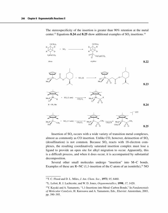
266 Chapter 8 Organometallic Reactions II
The stereospecificity of the insertion is greater than 90% retention at the metal center.33 Equations 8.24 and 8.25 show additional examples of SO2 insertions.34
H D
C(CH3)3
DH
CpFe(CO)2
threo
+ SO2
S
D H
C(CH3)3
DH
erythro
Fe(Cp)(CO)2O
O
8.22
Fe
Me3P
C O
O
+ SO2 (l) Fe
Me3P
C SO
O O O
O O
8.23
Rh
Cl
Me3P R
R = Ph, Me
+ SO2 (1 atm)CH2Cl2
Rh
Cl
Me3P SR
O O
8.24
Ir
TfO
Me3P CH3
+ SO2 (<1 atm)CD2Cl2
Ir
TfO
Me3P SCH3
O O
CH3CNIr
CH3CN
Me3P SCH3
O O
−OTf
8.25
Insertion of SO2 occurs with a wide variety of transition metal complexes, almost as commonly as CO insertion. Unlike CO, however, deinsertion of SO2 (desulfination) is not common. Because SO2 reacts with 18-electron com-plexes, the resulting coordinatively saturated insertion complex must lose a ligand to provide an open site for alkyl migration to occur. Apparently, this is a difficult process, and when it does occur, it is accompanied by substantial decomposition.
Several other small molecules undergo “insertion” into M−C bonds. Examples of these are R−NC (1,1-insertion of the C-atom of an isonitrile),35 NO
33T. C. Flood and D. L. Miles, J. Am. Chem. Soc., 1973, 95, 6460.34L. Lefort, R. J. Lachicotte, and W. D. Jones, Organometallics, 1998, 17, 1420.35Y. Kayaki and A. Yamamoto, “1,1-Insertions into Metal–Carbon Bonds,” In Fundamentals of Molecular Catalysis, H. Kurosawa and A. Yamamoto, Eds., Elsevier: Amsterdam, 2003, pp. 390–395.

8-2 Nucleophilic Addition to the Ligand 267
(1,1-insertion of the N-atom),36 and CO2 (1,2-insertion).37 Discussion of these and other insertions is beyond the scope of this text.
8-2 NUCLEOPHILIC ADDITION TO THE LIGANDA nucleophile may attack an organometallic complex—substituted with at least one unsaturated ligand (e.g., CO, alkene, polyene, arene)38—in a variety of ways, as shown in Scheme 8.6. Path a involves nucleophilic attack at the metal, which was already discussed in Chapter 7. Nucleophilic attack at the metal (via a four-centered transition state) is also of importance with regard to transmetallation reactions in which alkyl, alkenyl, alkynyl, and aryl groups may be transferred from either ionically bonded main group organometallic compounds, such as Grignard reagents, or more covalent compounds, such as R−Hg−Cl. These reactions were discussed in Section 6-1; we will see how they may be applied to organic synthesis in Chapter 12. Path b also involves nucleophilic attack at the metal, but instead of displacement, a syn insertion of an unsaturated ligand between the metal and the nucleophilic ligand can occur, some of the details of which we discussed earlier in Chapter 8. In contrast to the first two paths, path c shows the nucleophile attacking the ligand. It is this route that we shall consider in our discussion of nucleophilic reactions, because such a pathway offers the chemist numerous possibilities for accomplishing synthetic transformations that would be impossible without the presence of the metal. Note that with path c, the hapticity of the π ligand decreases by one and the overall charge on the complex becomes more negative by one unit.
Path c demonstrates a phenomenon that often occurs in organometallic chemistry—umpolung. Umpolung is a German word that translates into English approximately to mean “reversal of polarity.” One example of umpolung from the realm of organic chemistry is shown in equation 8.26 where an electrophile, CH3I, adds to a dithiane to give a ketone.
36S. Niu and M. B. Hall, J. Am. Chem. Soc., 1997, 119, 3077.37Transition metal-catalyzed insertion of CO2 into M–H and M–C bonds could be an impor-tant pathway toward utilization of this abundant C1 molecule in organic synthesis and for industrial-scale processes, potentially replacing the use of CO. For examples of CO2 inser-tion, see R. Johansson and O. F. Wendt, Dalton Transactions, 2007, 488; A. R. Cutler, P. K. Hanna, and J. C. Vites, Chem. Rev., 1988, 88, 1363; and W. J. Evans, C. A. Seibel, J. W. Ziller; and R. J. Doedens, Organometallics, 1998, 17, 2103. For another review, which discusses (in part) the utilization of CO2 by way of M–C insertion, see T. J. Marks, et al., Chem. Rev., 2001, 101, 953.38The latter three groups are generally also known as π ligands.

268 Chapter 8 Organometallic Reactions II
RC
H
OHS SH
BF3 RC
H
S S BuLi
RC
S S
CH3 I RC
CH3
S S Hg(II)/H2O
RC
CH3
O
Nucleophilic attack at carbon
Electrophilic attack at carbon
Hemithioacetal 8.26
The overall transformation represents formally the attack of an electrophile at the carbon of a carbonyl group. Normally, only nucleophiles attack carbonyl car-bon atoms (as indicated in the first step of equation 8.26) because these carbons represent electron-deficient sites. By converting the carbonyl to a hemithioacetal and pulling off the now relatively acidic proton with base, the carbonyl carbon becomes nucleophilic instead of electrophilic.
Alkenes, polyenes, arenes, and CO normally do not react with nucleophiles because these species are already electron rich. When these π ligands complex with a metal, however, (especially if the metal is electron deficient due to the presence of other electron-withdrawing ligands or due to a relatively high oxidation state), they are forced to give up some of their electron density to the attached metal com-plex fragment. The complexed ligands are now electron deficient compared with
Scheme 8.6Reactions of Nucleophiles with Metal Complexes
Ln(X)M
R
Nuc: −Nuc:−
Nuc:−
Ln(Nuc)M
R
R
Ln(Nuc)(X)M−
or
or
Ln−1(Nuc)(X)M−Ln(X)M
Nuc
Nuc
R
Ln(X)M
Ln(X)M
R
Nuc
ab
c
R
+
R

8-2 Nucleophilic Addition to the Ligand 269
their free state. Nucleophilic attack on them is now possible, giving a substituted ligand that can either stay attached to the metal or be released from the metal by numerous methods such as β-elimination or oxidative cleavage (Section 8-4-1).
The tendency for a nucleophile to attack an unsaturated ligand directly is a function of the electron density on the metal (i.e., complexes with a formal positive charge on the metal are more reactive than neutral ones), the degree of coordinative saturation of the metal (unsaturated metals have a higher probability of attack directly at the metal), and the presence of π-electron attracting ligands (such as CO) that can absorb some of the increased electron density on the metal after attack has occurred.
8-2-1 Addition at CO and Carbene LigandsEquations 8.27 to 8.29 illustrate that carbonyl and carbene ligands can undergo nucleophilic reactions. In equation 8.27, NaBEt3H delivers a hydride to the car-bonyl ligand to yield a relatively rare Pt–formyl complex.39 Attack by OH– on one of the CO ligands in Fe(CO)5 liberates CO2 in equation 8.28.40 This is a key step in the iron-catalyzed41 water–gas “shift reaction,” a process used to produce H2 from a mixture of CO and H2O. Equation 8.29 illustrates a Fischer carbene com-plex42 undergoing attack by a Io amine to yield a product that requires replacement of OMe by NRH2. This is analogous to a reaction in organic chemistry known as aminolysis (shown also for comparison in equation 8.30), where the amine nucleophile attacks the carbon to produce a tetrahedral intermediate. Breakdown of the intermediate yields the substituted product plus alcohol (or alkoxide) as the leaving group. The carbene complex in this case reacts as if it were a carboxylic acid derivative.
P(t-Bu)2
P(t-Bu)2
Pt CONaBEt3H
THF
P(t-Bu)2
P(t-Bu)2
Pt CH
O
8.27
39L. Schwartsburd, E. Poverenov, L. J. W. Shimon, and D. Milstein, Organometallics, 2007, 26, 2931. The steric bulk of the PCP pincer ligand helps to stabilize the Pt–CO complex, and the electronic properties of the naphthyl group enhance the susceptibility of the CO group toward reaction with a nucleophile.40This reaction is analogous to the loss of CO2 under thermal conditions from a β-carbonyl carboxylic acid such as malonic acid, CH2(COOH)2.41J. W. Reppe, Annalen, 1953, 582, 121.42H. Werner, E. O. Fischer, B. Heckl, and C. G. Kreiter, J. Organomet. Chem., 1971, 28, 367.

270 Chapter 8 Organometallic Reactions II
(CO)4Fe C O + :OH− (CO)4FeC
O
H
O
(CO)4Fe H + CO2
8.28
(CO)5Cr C
OCH3
Ph
+ N R
H
H
C NH2R
OCH3
Ph
(CO)5Cr (CO)5Cr C
NHR
Ph
+ CH3OH
8.29
O C
OCH3
Ph
+ RNH2 O C
NHR
Ph
+ CH3OH
8.30
8-2-2 Addition to π LigandsNumerous examples of nucleophilic addition to π hydrocarbyl ligands exist.43 The regiochemistry of these additions to cationic metal complexes has been well studied and summarized by Davies, Green, and Mingos44 (DGM) as a set of rules. These rules can be used to predict where the nucleophile will add to a variety of π-ligands when the reaction is under kinetic control. A summary of the rules follows.
1. Nucleophilic attack occurs preferentially at even instead of odd coordi-nated polyenes.
2. Nucleophilic addition to open coordinated polyenes is preferred over addition to closed polyenes.
3. For even, open polyenes, nucleophilic addition occurs preferentially at the terminal position; for odd, open polyenes, attack occurs at the terminal positions only if the metal fragment is strongly electron withdrawing.
Figure 8-4 provides some examples of ligands attached to the generic metal, M, according to their classification under the DGM scheme. Note that the DGM system classifies a ligand as even or odd depending on its hapticity and electron count, assuming that it is a neutral ligand. Thus, η3–allyl (3 e–) is an odd, open
43L. S. Hegedus, “Nucleophilic Attack on Transition Metal Organometallic Compounds,” In The Chemistry of the Metal–Carbon Bond, F. R. Hartley and S. Patai, Eds., Wiley–Interscience: New York, 1985, pp.401–512.44S. G. Davies, M. L. H. Green, and D. M. P. Mingos, Tetrahedron, 1978, 34, 3047; a simplified explanation of the rules and several examples are provided in S.G. Davies, Organotransition Metal Chemistry: Applications to Organic Synthesis, Pergamon Press: Oxford, 1982, pp. 116–186.

8-2 Nucleophilic Addition to the Ligand 271
ligand, and η4– cyclohexadienyl (4 e–) is even and also open.45 The first two rules may be simplified further.
Even1. before odd.Open 2. before closed.
Figure 8-5 expresses rules 1 and 2 another way by ranking the various ligands in terms of their relative reactivity to nucleophilic attack.
Equations 8.31 to 8.34 provide some examples of some cationic complexes, polysubstituted with π-ligands, that seem to obey the rules.
45Note that a cyclic conjugated system involving all atoms of a ring, such as benzene or Cp, is considered closed.
Figure 8-4 Classification of π Ligands
M M M
M M M
Odd closed Odd open Odd open
Even closed Even open Even open
η5 η5 η3
η6η4η6
Figure 8-5 Relative Reactivity of π Ligands
> > > > >>Even:
> > >Odd:
Open Closed
ClosedOpen

272 Chapter 8 Organometallic Reactions II
WMe PPhMe2
WMe
PPhMe2
8.31
RhMeO−
Rh
OMe
H
8.32
Mo MeS−Mo
SMe
8.33
CoCN−
Co
CN
H
8.34
DGM and others have attempted to explain the basis for these rules. Rule 1 may be explained on the basis of the reactions being under charge control. Consider the orbitals of the π ligand once attached to the metal (Figure 8-6). For even ligands the HOMO is doubly occupied.46 If the metal is quite electron deficient,
46One exception to this statement is cyclobutadiene. This molecule has two degenerate (equal energy) HOMOs, each of which is singly occupied with an electron. Nucleophilic attack on other even polyenes is preferred according to Rule 1. Cyclobutadiene is, however, attacked in preference to odd polyenyl ligands.

8-2 Nucleophilic Addition to the Ligand 273
Figure 8-6π MOs of Allyl and 1,3-Butadiene
Allyl
Butadiene
HOMO
LUMO
LUMO
HOMO
ψ1
ψ2
ψ3
ψ4
ψ3
ψ2
ψ1

274 Chapter 8 Organometallic Reactions II
up to two electrons could transfer from the HOMO of the ligand to the metal. The net charge on the ligand could then be as high as +2. Odd π ligands are singly occupied in the HOMO. With odd ligands, bonding electrons are contributed by both the ligand and the metal. At most, one electron may be transferred from the ligand to the metal, and thus the net charge on the ligand will be maximally +1. In a complex with both an even and an odd π ligand, the even ligand will be more positive (and thus more susceptible to attack by nucleophiles) than the odd by up to one unit of positive charge.
Rule 2 states than open ligands will undergo nucleophilic attack before closed ligands. Although not explicitly proven by DGM, it seems reasonable that, for cyclic, closed polyenes, the positive charge on the ring is more evenly distributed due to symmetry. As a consequence, any site on a closed ligand will have less positive charge than at least some sites on an open ligand with the same number of π electrons.
There does, however, seem to be an empirical basis for the increased reactivity of open over closed ligands when the reactivity of ethene and benzene ligands is compared. Work reported after DGM’s initial investigations by Bush and Angelici47 indicates that there is a relation between the tendency of a ligand to undergo nucleophilic attack and the effec-tive force constant,48 kCO
*, when reactions are under kinetic control. The reasoning goes as follows:
The electron-withdrawing nature of a positive metal center should have the same effect on a π ligand as it would on a carbonyl group. The IR stretching frequency of a car-bonyl (more accurately the force constant, k) is a reflection of the electronic interaction of the carbonyl group and the metal. Electron-poor metals (or metals also coordinated to π acids) do not backbond effectively to the carbonyl. Thus, the Lewis structure 17 makes a substantial contribution to the actual structure of the complex.
LnM COδ+
17
The more electron-withdrawing the metal fragment, the more complete the σ donation to the metal. This will increase the triple bond character of the C−O bond and thus increase the force constant. Bush and Angelici analyzed a number of cationic complexes containing π ligands for their tendency to undergo addition with a variety
47R. C. Bush and R. J. Angelici, J. Am. Chem. Soc., 1986, 108, 2735.48If we assume that bonds are analogous to springs with varying degrees of stiffness, the force constant, k, measures the stiffness of the bond; see Section 4-1 for more details.

8-2 Nucleophilic Addition to the Ligand 275
of nucleophiles. The force constant, kCO*, represents the effective force constant if the π
ligand were replaced by the equivalent number of carbonyl groups. For instance, [(C2H4)Rh(PMe3)2Cp]2+ would be equivalent to [(CO)Rh(PMe3)2Cp]2+, and [(η6–benzene)Mn(CO)3]+ would correspond to three CO ligands grouped in a facial arrangement on [Mn(CO)6]+. Bush and Angelici found, in general, that addition of a particular kind of nucleophile, such as an amine or a phosphine, would not occur in complexes when kCO
* was below a certain threshold value. One particularly interesting result from this analysis was that the threshold value of kCO
* for addition of a particular kind of nucleophile—phosphines, for instance—was lower when ethene (an open ligand) was coordinated to the metal than when ben-zene was (a closed ligand). In other words, the ethene ligand, attached to a number of different metals, seemed to be more susceptible to attack by a variety of nucleophiles than the benzene ligand. We must be careful not to extrapolate this analysis too far since nucleophilic addition could be influenced by both kinetic and thermodynamic factors. In this limited case, however, there does seem to be a way of predicting whether a complex containing either a benzene or ethene ligand (or both) will undergo addition. If addition does occur, the ethene reacts preferentially to benzene in accordance with Rule 2.
Rule 3 considers the regiochemistry of attack of the nucleophile. For even, open ligands, the nucleophile tends to attack at the terminal position of the ligand. Consider 1,3-butadiene as a typical example. The LUMO of butadiene, (Ψ3),49 has larger lobes at the termini of the orbital than in the middle (Figure 8-6). The incoming nucleophile (if it is reasonably soft) will be attracted to that part of the orbital with the biggest lobe.50
The picture is more complicated when we apply Rule 3 to odd, open ligands. Attack may occur at the termini or internal positions depending on the electron richness of the attached metal fragment. Usually attack occurs at the terminal carbons of η3–allyl ligands, but for relatively electron-rich metal complexes such as [Cp2Mo(η3–allyl)]+ (equation 8.3551) and [Cp*(PMe3)Rh(η3–allyl)]+ (equation 8.3652), addition occurs at C-2 to form metallacyclic products.
Cp2MoClMg Cp2Mo
H
8.35
49Assuming that there is still electron occupation of Ψ2.50R. Pankayatselvan and K. M. Nichols, J. Organomet. Chem., 1990, 384, 361. Nucleophilic attack at the terminal position of cationic η4–diene complexes almost invariably occurs. See J.-S. Fan and R.-S. Liu, Organometallics, 1998, 17, 1002, for an example of addition of Grignard reagents to the internal position of [CpW(CO)2(η4–1,3-cyclohexadiene)]+.51M. Ephretikine, B. R. Francis, M. L. H. Green, R. E. Mackenzie and M. J. Smith, J. Chem. Soc. Dalton Trans., 1977, 1131.52R. A. Periana and R. G. Bergman, J. Am. Chem. Soc., 1984, 106, 7272.

276 Chapter 8 Organometallic Reactions II
RhH BEt3 Li+
Rh
H
H
Cp*
Me3P
Cp*
Me3P 8.36
We can understand this difference in regiochemistry if we consider the molecular orbitals of the allyl system in Figure 8-6. For electron-rich metal fragments, the LUMO becomes ψ3, which has a large lobe (or high lack of electron density) at C-2. Nucleophiles thus would be attracted to the middle carbon of the allyl ligand in these cases. Electron-poor metal fragments, on the other hand, pull electron density out of the allyl ligand, and the LUMO becomes ψ2, an MO with the largest lobes at the ends of the system. Incoming nucleophiles thus tend to attack at these positions.53
The stereochemistry of addition in equation 8.36 is interesting. If LiEt3BD is used instead of its protium analog, the deuterium ends up at the C-2 of the allyl ligand syn to the Cp*. As we shall see in the examples to follow, nucleophilic addition onto π ligands almost always occurs anti to the metal fragment. This seems reasonable because anti addition involves a pathway with less steric hindrance than syn.
A more recent experimental and computational study of η3–allyl–Pd cationic complexes confirmed the tendency of nucleophiles to attack the terminal posi-tions of the allyl ligand as long as π-accepting ligands are present.54 If σ-donating ligands are attached to palladium, which would pump electron density into the allyl ligand, attack occurs mainly at the C-2 position. Equations 8.37 and 8.38 summarize these results.
Pd
CO2EtEtO2C
CH3
+
Cl
Pd
Cl
PdCO2Et
CO2Et
CH3
+
CO2EtEtO2CCH3
(+ Cl−)
98% 2%
8.37
53See also T. Suzuki, G. Okada, Y. Hioki, and H. Fujimoto, Organometallics, 2003, 22, 3649, for a theoretical treatment of nucleophilic addition to π–allyl–Mo cationic complexes. This study sheds light on the tendency for nucleophiles to attack primarily at the terminal posi-tions of the allyl ligand.54A. Aranyos, K. J. Szabó, A. M. Castano, and J.-E. Bäckvall, Organometallics, 1997, 16, 1058.
Exercise 8-10 Propose a mechanism that might explain why deuterium adds syn to the Cp* ligand in equation 8.36.

8-2 Nucleophilic Addition to the Ligand 277
Pd
NMe2Me2N CO2EtEtO2C
CH3
+
Cl
Pd
NMe2Me2N
Cl
PdCO2Et
CO2Et
CH3
+
CO2EtEtO2CCH3
(+ Cl−)
< 1% > 99%
NMe2Me2N
8.38
Pd(PR3)2
R2
R1
R1 = H or CH3R2 = OCH3 or CH3
18
When allyl ligands are unsymmetrically substituted, experiment shows that cationic (PR3)2Pd(η3–R1–R2–allyl) complexes 18 (one end of the allyl group is either substituted with two CH3 groups or one OCH3 group) undergo attack at the more-substituted terminal position as long as R1 and R2 are not sterically bulky. A theoretical study of such complexes (PR3 = PH3) using DFT calculations dupli-cated experimental results, especially when solvent effects were considered.55 Figure 8-7 suggests a qualitative explanation for this regiochemistry by showing the π MOs of the unsymmetrical allyl ligand where one or more electron-donating groups (Y) are substituted at C-1. The occupied π2 MO (HOMO) of the complex shows a relatively large lobe at C-3, which means an electron-rich ligand would not be attracted to this position compared with C-1 (i.e., the filled–filled repul-sive interaction is minimized if the nucleophile attacks at C-1). More important, the LUMO (π3) has a larger lobe at C-1 than at C-3, which means that there is a stronger HOMO (nucleophile)–LUMO (π3) interaction at C-1 than at C-3. Taken together, these two interactions direct the nucleophile to the more substituted position, C-1.
55F. Delbecq and C. Lapouge, Organometallics, 2000, 19, 2716, and references therein that discuss experimental work on these complexes.
Figure 8-7 π-MOs of Unsymmetrical Allyl Ligands
Y Y Y3 2 1 1 12 23 3
HOMO LUMOπ1 π2 π3
NucHOMO
NucHOMO
Morefavorable
Morefavorable
PdLnPdLnPdLn
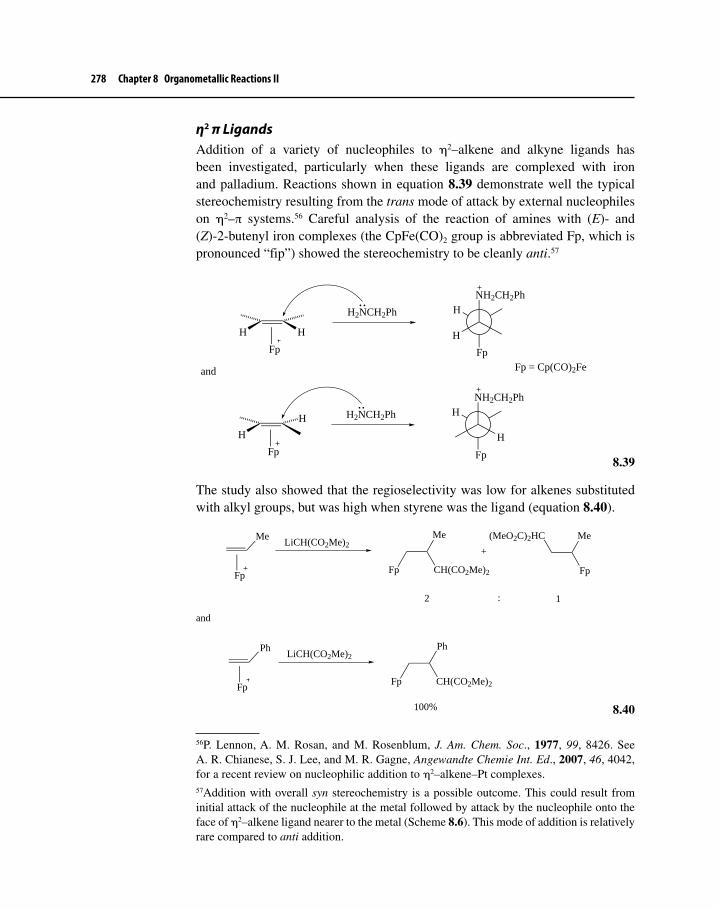
278 Chapter 8 Organometallic Reactions II
η2 π LigandsAddition of a variety of nucleophiles to η2–alkene and alkyne ligands has been investigated, particularly when these ligands are complexed with iron and palladium. Reactions shown in equation 8.39 demonstrate well the typical stereochemistry resulting from the trans mode of attack by external nucleophiles on η2–π systems.56 Careful analysis of the reaction of amines with (E)- and (Z)-2-butenyl iron complexes (the CpFe(CO)2 group is abbreviated Fp, which is pronounced “fip”) showed the stereochemistry to be cleanly anti.57
HH
Fp
H2NCH2Ph
Fp
H
NH2CH2Ph
H
and
H
H
Fp
H2NCH2Ph
Fp
H
NH2CH2Ph
H
Fp = Cp(CO)2Fe
8.39
The study also showed that the regioselectivity was low for alkenes substituted with alkyl groups, but was high when styrene was the ligand (equation 8.40).
Me
Fp
LiCH(CO2Me)2Me
CH(CO2Me)2Fp
Me
Fp
(MeO2C)2HC
+
2 1:
and
Ph
Fp
LiCH(CO2Me)2Ph
CH(CO2Me)2Fp
100%
8.40
56P. Lennon, A. M. Rosan, and M. Rosenblum, J. Am. Chem. Soc., 1977, 99, 8426. See A. R. Chianese, S. J. Lee, and M. R. Gagne, Angewandte Chemie Int. Ed., 2007, 46, 4042, for a recent review on nucleophilic addition to η2–alkene–Pt complexes.57Addition with overall syn stereochemistry is a possible outcome. This could result from initial attack of the nucleophile at the metal followed by attack by the nucleophile onto the face of η2–alkene ligand nearer to the metal (Scheme 8.6). This mode of addition is relatively rare compared to anti addition.

8-2 Nucleophilic Addition to the Ligand 279
Addition to unsymmetrical η2–alkenes seems to occur generally at the more substituted carbon, analogous to a reaction from the realm of organic chemis-try known as solvomercuration (equation 8.41). Computational analysis58 using extended Hückel theory of attack at alkene ligands has indicated that a “slip-page” occurs from the η2-complex (19) to the η1-complex (20) along the path to product, where ∆ is a measure of the slippage from η2 (∆ = 0) to η1 (∆ = 0.69). Calculations show that, for donor substituents such as alkyl groups, the energies of the pathways leading to attack at the more substituted position vis-a-vis the less substituted do not differ greatly. A phenyl group, on the other hand, is slightly electron withdrawing yet can effectively stabilize, through resonance, the posi-tive charge that would develop in the η1-complex (21). Attack, therefore, occurs exclusively at the benzylic position.
Me
Me
+ Hg(OAc)2HMe
HMe
Hg
OAc
HMe
HMe
Hg
OAc
δ+
δ+
ROHH
H
HgOAc
RO
MeMe
H
H
MLn
19
MLn
∆
20
HPh
HH
MLn
21
δ+
Although Pt–alkene complexes are normally not as reactive as the correspond-ing Pd complexes toward nucleophilic addition, platinum can serve usefully as a catalyst in these reactions.59 The following cyclization was mediated by a Pt–PPP–pincer complex 22, demonstrating Markovnikov addition at each step of the cycli-zation (equation 8.42).60 The reaction is stereoselective and mimics the cyclization of squalene epoxide to lanosterol, a key step in the biosynthesis of cholesterol.
Pt
PPh2
PhP
PPh2
(BF4−)2
2+
22
58O. Eisenstein and R. Hoffmann, J. Am. Chem. Soc., 1980, 102, 6148, and 1981, 103, 4308; A. D. Cameron, V. H. Smith, and M. C. Baird, J. Chem. Soc. Dalton Trans., 1988, 1037.59A. R. Chianese, S. J. Lee, and M. R. Gagné, Angew. Chem. Int. Ed., 2007, 46, 4042.60J. H. Koh and M. R. Gagné, Angew. Chem. Int. Ed., 2004, 43, 3459.
8.41

280 Chapter 8 Organometallic Reactions II
OMe
H
2+(PPP)Pt
OMe
H
+
OMe
H
(PPP)Pt (PPP)Pt
86 : 14
−H+
NaBH4/MeOH NaBH4/MeOH
OMe
MeH
+
OMe
MeH
8.42
η3–Allyl LigandsA wide variety of nucleophiles add to an η3–allyl ligand. Desirable nucleophiles typically include stabilized carbanions such as –:CH(COOR)2 or Io and IIo amines. Unstabilized nucleophiles such as MeMgBr or MeLi often attack the metal first and then combine with the π–allyl by reductive elimination. The Tsuji–Trost reaction, which is typified by the addition of stabilized carbanions to η3–allyl ligands complexed to palladium followed by loss of the resulting substituted alk-ene, comprises an extremely useful method of constructing new C−C bonds, and many applications of this reaction have appeared in the literature.61 Equation 8.43 illustrates an example of a Pd-catalyzed addition of a stabilized enolate to an allyl acetate.62 The initial step in the catalytic cycle is oxidative addition of the allyl acetate to the Pd(0) complex, followed by η1– to η3–allyl isomerization, and then attack by the nucleophile to a terminal position of the η3–allyl ligand. We will discuss the Tsuji–Trost reaction, especially in regard to its utility in chiral synthesis,63 more extensively in Chapter 12.
61B. M. Trost, Acc. Chem. Res., 1980, 13, 385; J. Tsuji, Tetrahedron, 1986, 42, 4361; L. S. Hegedus, Transition Metals in the Synthesis of Complex Organic Molecules, 2nd ed., University Science Books: Sausalito, CA, 1999, pp. 250–282; and J. Tsuji, Palladium Reagents and Catalysts, Wiley: Chichester, England, 2004, Chap. 4.62J. Tsuji, Pure Appl. Chem., 1989, 61, 1673.63See B. M. Trost and D. L. Van Vranken, Chem. Rev., 1996, 96, 395, for an account of the use of the Tsuji–Trost reaction in chiral synthesis.
Exercise 8-11 Propose a stepwise mechanism for the polycyclization reaction shown in equation 8.42. Does each ring closure step involve Markovnikov addition to a C=C bond? Explain.

8-2 Nucleophilic Addition to the Ligand 281
CO2Me
O
+ Me3Si Ph
OAc
5 mol% Pd(0)
PBu3/THF/25 oC
Me3Si
O
CO2Me
Ph
83%
via
Me3Si Ph
LnPdOAc 8.43
π–Arene Ligandsπ–Arene complexes offer interesting possibilities for demonstrating the utility of umpolung. Group 6 (especially Cr) metal–arene compounds64 have been particu-larly well investigated and exploited for their synthetic utility. Complexation of a transition metal to the arene results in the maintenance of the aromaticity of the ring, but this binding also provides enhanced reactivity to not only the metal but also the carbon atoms of the arene that are bonded to the metal and to even more remotely attached atoms.65 Figure 8-8 illustrates the changes in reactivity caused by metal complexation.
64(a) For reviews on the chemistry of Cr(0)–arene complexes see S. Maiorana, C. Baldoli, and E. Licandro, “Carbonylchromium(0) Complexes in Organic Synthesis,” In Metal Promoted Selectivity in Organic Synthesis, A. F. Noels et al., Eds., Kluver Academic: Amsterdam, 1991, pp. 261–286; (b) R. D. Pike and D. A. Sweigert, Coord. Chem. Rev., 1999, 187, 183; and (c) for a recent account of the utility of such complexes in organic synthesis, see A. R. Pape, K. P. Kaliappan, and E. P. Kündig, Chem. Rev., 2000, 100, 2917.65P. v. R. Schleyer, B. Kiran, D. V. Simion, and T. S. Sorenson, J. Am. Chem. Soc., 2000, 122, 510; for an account of computational studies on the reactivity of η6–arene–Cr complexes,
Figure 8-8 Reactivity at Different Sites on Metal–Arene Complexes
C R
H
X
Y
H
Enhancedacidity
Enhanced nucleophilicsubstitution
Enhanced nucleophilic
addition
MLn
Enhanced steric
hindrance
Enhanced tendencyfor solvolysis
Enhancedacidity

282 Chapter 8 Organometallic Reactions II
Table 8-1 Acidities of Chromium–Aryl Carboxylic Acids Compared with Noncomplexed Analogsa
Acid pKa Acid pKa
PhCOOH 5.68 PhCH2COOH 5.54(PhCOOH)Cr(CO)3 4.77 (PhCH2COOH)Cr(CO)3 5.02p-NO 2−C 6H 4−COOH 4.48 p-NO2−C6H4−CH2COOH 5.01
aData taken from Footnote 64a.
When M = Cr, profound effects on the acidity of arene and neighboring protons, electron density of the arene, and steric hindrance at the metal occur. As Table 8-1 indicates, the metal exerts an electron-withdrawing effect on an arene comparable to that of a para-NO2 group. Metallation of the ring using strong bases such as butyllithium occurs at even −78 oC, a much lower temperature than would be required in the noncomplexed arene.
The electron-withdrawing effect of the metal fragment is also manifested in the enhanced ability of complexed arenes to undergo nucleophilic aromatic substitution, a reaction normally requiring strong nucleophiles in noncomplexed arenes. The reaction of methoxide with the chloroarene chromium complex illus-trated in equation 8.44 gives the corresponding methoxyarene complex at a rate comparable to that for substitution by methoxide on noncomplexed 1-nitro-4-chlorobenzene. As with their noncomplexed counterparts in organic chemistry, nucleophilic substitutions on coordinated arenes go through an intermediate σ-complex, 23, known as a Meisenheimer complex.66
Cl
Cr(CO)3
CH3O−
OCH3
Cl
Cr(CO)3
OCH3
Cr(CO)3
+ Cl−
23
8.44
When a substituent is present that is not a good leaving group, the direct-ing effects of that substituent tend to be the reverse of what they would be for electrophilic substitution on the uncomplexed arene. For instance, in equation 8.45 the electron-donating OCH3 group directs primarily to the meta position, whereas in 8.46 the electron-withdrawing CF3 group directs to the para position
see also C. A Merlic, M. M. Miller, B. N. Hietbrink, and K. N. Houk, J. Am. Chem. Soc., 2001, 123, 4904.66See J. McMurry, Organic Chemistry, 7th ed., Thompson Brooks–Cole: Belmont, CA, 2008, pp. 572–576, for a concise discussion of nucleophilic aromatic substitution.

8-2 Nucleophilic Addition to the Ligand 283
primarily. The last step in these reactions involves oxidative cleavage (using I2) of the arene–metal bonds.
OCH3
Cr(CO)3
1) LiCH2CO2Et
2) I2
EtO2CCH2
OCH3
o : m : p = 4 : 96 : 0
8.45
CF3
Cr(CO)3
1) LiY
2) I2
Y
CF3
o : m : p = 0 : 30 : 70
Y = C
CN
Me
O
O
8.46
Again, the stereochemistry of attack is such that the nucleophile adds anti to the metal.
The rationalization for the regiochemistry of addition when a directing group is present and when the reaction is under kinetic control is based on inspection of the LUMO of the metal arene complex.67 If the LUMO of the arene complex and the HOMO of the base are reasonably close in energy, then inspection of the coefficients on the LUMO offers some insight into the ori-entation of attack on the aromatic ring. The LUMO, when the substituent is electron donating, is given by 24 and shows large coefficients at the ortho and meta positions. When the substituent is electron withdrawing, however, the coefficients are large mainly at the 1 and 4 positions as shown in 25. We would expect an incoming nucleophile to attack at the positions where the coeffi-cients are large because this would provide the best overlap with the lobe(s) of the nucleophile’s HOMO. This analysis is reasonable, however, only if the reaction is under kinetic control and if considerations of steric hindrance are unimportant.
67M. F. Semmelhack, G. R. Clark, R. Farina, and M. Saeman, J. Am. Chem. Soc., 1979, 101, 217; for a more recent discussion of orientation effects based on kinetic and thermodynamic control, see E. P. Kunding, V. Desobry, D. P. Simmons, and E. Wenger, J. Am. Chem. Soc., 1989, 111, 1804.

284 Chapter 8 Organometallic Reactions II
Y
24
Y is electrondonating
Topview
YSideview
Y
25
Y is electronwithdrawing
Y
Equations 8.47 to 8.49 illustrate other examples of nucleophilic addition to cyclic π ligands. The cationic Mn–arene complex in 8.47,68 produced by ligand substitution in the presence of a Lewis acid, undergoes nucleophilic substitution by a variety of alkoxide and amine nucleophiles. In equation 8.48, the molybde-num η4–diene complex undergoes attack by methyllithium to give an η3–allyl intermediate.69 Hydride abstraction with an electrophile known as trityl cation (Ph3C+) yields the product with the methyl group anti to the metal fragment. Reaction of the η6–trienyl Mn complex with a stabilized carbanion such as malonate results in an η5–pentadienyl complex, again showing the nucleophile anti to the metal (equation 8.49).70 Note that the last two cases explicitly show the typical pattern that accompanies nucleophilic addition to π ligands: the charge on the complex becomes more negative by one unit and the hapticity of the π ligand decreases by one.
Br
Mn(CO)3
PhBr + BrMn(CO)5AlCl3
∆Me2NH
NMe2
Mn(CO)3
8.47
68P. L. Pauson and J. A. Segal, J. Chem. Soc. Dalton, 1975, 1677, 1683.69J. W. Faller, H. H. Murray, D. L. White, and K. H. Chao, Organometallics, 1983, 2, 400.70A. J. Pearson, P. Bruhn, and I. C. Richards, Tetrahedron Lett., 1984, 25, 387.

8-3 Nucleophilic Abstraction 285
Mo COOC + CH3Li Mo COOC
H
H3C
H
HPh3C
Mo COOC
H3C
H H
+ Ph3CH 8.48
Mn(CO)3
+ :CH(CO2Me)2
Mn(CO)3
CH(CO2Me)2
H
8.49
8-3 NUCLEOPHILIC ABSTRACTIONInstead of simply adding to a ligand, the possibility exists for a nucleophile to attack the ligand in such a way that part or all of the original ligand is removed along with the nucleophile. We call this reaction nucleophilic abstraction.
Abstraction of alkyl groups by nucleophiles is relatively uncommon, because reduced metals are generally poor leaving groups. If the metal fragment is first oxidized, however, nucleophilic attack on alkyl ligands at the carbon attached to the metal becomes much more feasible. Oxidation makes the leaving metal frag-ment less basic and also weakens the M−C bond. The halogens Br2 and I2 serve effectively as M−C cleaving agents, for example in the oxidatively-driven, nucle-ophilic abstraction shown in equation 8.50.71
H D
C(CH3)3
DH
CpFe(CO)2
X2
X = Br, I X
D H
C(CH3)3
DH
8.50
Note that the reaction proceeds with inversion of configuration at the stereogenic center attached to the metal. It is not clear exactly what the initial function of the halogen is in the reaction, however. Scheme 8.7 presents two possible scenarios for the reaction. In path a, the halogen oxidatively adds to the metal to give a cat-ionic complex. The remaining nucleophilic halide ion attacks the complex at the
71G. M. Whitesides and D. J. Boschetto, J. Am. Chem. Soc., 1971, 93, 1529.

286 Chapter 8 Organometallic Reactions II
α-carbon of the alkyl group, giving inversion of configuration (note that RE with retention of configuration at the α-carbon is also possible). Path b, on the other hand, shows oxidation of the metal without addition, followed by nucleophilic attack by X–.
We can also envision the overall process of halogen cleavage as an electro-philic process if the first step is the addition of X+ (from X2) to the metal, analo-gous to the addition of halogen to a C=C bond in organic chemistry. Addition of halogen to alkenes is a two-step process where attack of the electrophile occurs first to form an intermediate halonium ion (equation 8.51), followed by attack by the nucleophile, X–. We see that sometimes the designation “nucleophilic” or “electrophilic” can be rather arbitrary, and it depends upon one’s perspective in describing the reaction. We shall consider electrophilic processes in more detail in Section 8-4.
Me
Me+ Br2
Me
MeBr
H
HH
H
Br−
Br
HH3C
Br
CH3H
8.51
Equation 8.52, which is one of the reactions listed in Scheme 7.7, demon-strates an important example of nucleophilic abstraction. Here CH3OH acts as a nucleophile that attacks the σ–acyl group. Breakdown of the resulting tetrahedral intermediate yields the methyl ester and a reduced Pd complex.
CC
Ph
R
H
O PMe3
Pd Br
PMe3
CC
Ph
R
HOMe
OMeOH
(retention)+ HBr + LnPd
8.52
Scheme 8.7 Pathways for Oxidatively-Driven Nucleophilic Abstraction
R CR'R'' Mn
X2
a (OA)
X2b (Oxidation)
R CR'R'' Mn+2 X
X
R CR'R'' Mn+1
or
X−
(Nucleophilic attack or RE)R−CR'R''−X
+ Mn−XR CR'R'' Mn+1 X X−
X−
(Nucleophilic attack)R−CR'R''−X
+ Mn
n, n+1, and n+2 represent different oxidation states of the metal

8-3 Nucleophilic Abstraction 287
Nucleophilic abstraction of σ–acyl ligands is quite useful synthetically, especially when the metal is Pd. Scheme 8.8 illustrates a sequence of reactions that may be either stoichiometric or catalytic in that metal.72 Palladium is the metal of choice here because it readily forms σ–M−C complexes, which then undergo facile CO insertion and subsequent σ–acyl−Pd bond cleavage with a variety of nucleophiles. The first step involves OA of a vinyl or aryl halide to a Pd(0) com-plex (shown as LnPd in Scheme 8.8). Migratory insertion of CO (Section 8-1) gives the σ–acyl complex, which undergoes nucleophilic abstraction with MeOH to give the corresponding methyl ester. This sequence of reactions has synthetic applicability, because intermolecular nucleophilic abstraction produces a variety of linear acyl derivatives, and intramolecular attack provides cyclic compounds such as lactones or lactams.
72R. F. Heck, Pure Appl. Chem., 1978, 50, 691.
Scheme 8.8Nucleophilic Abstraction of σ–Acyl–Pd Complexes
LnPd
L
Pd
L
XAr
Ar C
O
Pd
L
L
X
L
Pd
L
XH
L = PR3 R = Alkyl X = Cl, Br, I
Ar−X
Starthere
CO
ROH
Ar C
O
OR
H−X

288 Chapter 8 Organometallic Reactions II
Another example of nucleophilic abstraction is the use of trimethylamine N-oxide (Me3NO), a widely-used reagent for decarboxylation of metal carbonyl complexes (equation 8.53).73 Equation 8.54 describes a reaction where the irid-ium dihydride complex undergoes CO abstraction while a similar monohydride complex undergoes hydride extraction. The reason for the difference in reactivity of Me3NO is not clear.74
LnM C O
O NMe3
LnM C O
O
NMe3
LnM + CO2 + NMe3
8.53
IrC
Ph3P H
PPh3
H
NCCH3
Me3N−O/CH3CN IrH3CCN
Ph3P H
PPh3
H
NCCH3
+ CO2 + Me3N
IrC
Ph3P NCCH3
PPh3
H
NCCH3
Me3N−OIr
C
Ph3P NCCH3
PPh3
+ Me3NOH+ ClO4−
+ CH3CN
and
ClO4−
2 ClO4−
ClO4−
ClO4−2+
O
O O
8.54
Equation 8.55 can be considered a nucleophilic abstraction of H+ from the arene ligand by a strong nucleophile. An alternate interpretation of this trans-formation is that it represents a Brønsted–Lowry acid–base reaction. Regardless of the viewpoint of the observer, the reaction is facile mainly because of the electron-withdrawing nature of the metal fragment.
Cr(CO)3
+ BuLiH
Cr(CO)3
Li+ BuH
8.55
The last example of nucleophilic abstraction shows removal of a methyl group from a Fischer carbene complex (equation 8.56).75 The course of this reaction is unusual because normally nucleophiles add to the carbene carbon, as we shall see in Chapter 10. In this case, however, the apparent steric bulk of the abstracting
73See, for example, K. Yang, S. G. Bott, and M. G. Richmond, Organometallics, 1994, 13, 3788 and M. O. Albers and N. Coville, J. Coord. Chem. Rev., 1984, 53, 227.74C. S. Chin, M. Oh, G. Won, H. Cho, and D. Shin, Bull. Korean Chem. Soc., 1999, 20, 85.75L. M. Toomey and J. D. Atwood, Organometallics, 1997, 16, 490.

8-4 Electrophilic Reactions 289
agent directs the course of the reaction toward abstraction rather than addition. The anionic metal carbonyl complex acts as a nucleophile in attacking the methyl group via an SN2 mechanism. When the methyl group is substituted with ethyl, the reaction is 70 times slower, which would be expected for an SN2 displacement.
(OC)5W
O
Ph
R
+ [Mn(CO)4(PPh3)]− (OC)5W
O
Ph
+ R−Mn(CO)4(PPh3)
R = Me, Et
8-4 ELECTROPHILIC REACTIONSReactions involving a metal complex and an electron-deficient species (the electrophile, E+) are common in organometallic chemistry and often useful syn-thetically. There are several possibilities for interaction of a metal complex and E+, some of which we have already encountered. For example, the insertion of SO2 (equation 8.22), electron deficient at sulfur, begins with attack by the elec-trophile at the carbon attached to the metal.
Just where and with what stereochemistry the electrophile will attack a metal complex depends upon a number of factors. If the reaction is controlled by fron-tier orbital interactions, then the point of attack on the complex is dictated by the electron density of the complex’s HOMO. Major lobes of the HOMO could be on the ligand or the metal or both. The stereochemistry of attack may depend on such factors as the steric hindrance of the metal fragment or even the nature of the solvent. Extensive study of electrophilic attack on specific metal complexes has uncovered some general trends for use as a basis in predicting how an electro-phile will react. We will limit our treatment of electrophilic attack to a few well-defined examples that illustrate the major pathways of a reaction where E+ either directly or indirectly interacts with a coordinated ligand. Again, we distinguish between addition reactions, where all or part of the electrophilic species adds to the coordinated ligand, and abstractions, in which E+ attacks in such a manner that all or part of the ligand is removed from the metal complex (see Table 7-1).
ElectrophilesThe term electrophile is synonymous with Lewis acids. Classifying electrophiles on the basis of their “strength” is virtually impossible (see Section 7-2-2). It is useful, however, to point out that we can classify Lewis acids according to the three types as described on the next page.76
76M. D. Johnson, “Electrophilic Attack on Transition Metal η1–Organometallic Compounds,” In F. R. Hadley and S. Patai, Eds., The Chemistry of the Metal–Carbon Bond, Wiley: London, 1985, Vol. 2, p. 515.
8.56

290 Chapter 8 Organometallic Reactions II
1. Metallic electrophiles, such as Hg(II), Tl(I), Ag(I), Ce(IV), Pt(IV), Au(III), or Ir(V)—most of which also have accessible oxidation states one or two units lower in value from those given above
2. Organic electrophiles, such as R3O+, Ph3C+, R−X, or (NC)2C=C(CN)2
3. Non-metallic electrophiles, such as X2, SOx, CO2, NOx+, or H+
Each of these classes of electrophiles may attack transition metal complexes. We will encounter examples of all three classes during the remainder of the discus-sion in this section of Chapter 8.
8-4-1 Metal–Carbon σ Bond CleavageThe use of an electrophile (e.g., H+ or X2) to remove a σ-bonded hydrocarbyl ligand from a metal is common in organometallic chemistry. Such a reaction constitutes an electrophilic abstraction of the entire ligand. Scheme 8.9 diagrams some of the many pathways available for this type of abstraction. Stereochemical outcomes include retention, inversion, and racemization and depend upon such factors as the nature of the metal, steric hindrance, the nature of E+, where the HOMO is located on the complex, and characteristics of the solvent.
Pathways • a and b represent a mechanism called SE2, which we encountered earlier in the discussion on SO2 insertion. Inversion77 (path a) or retention (path b) of stereochemistry may occur at the stereogenic center78 attached to the metal.Pathway • c is oxidative addition to give intermediates 26 and 27, which may suffer several fates.Pathway • d, emanating from 26, is ligand dissociation to give a stable car-bocation followed by nucleophilic capture to give racemic79 product.Also originating from• 26 is pathway e, RE, from which we would expect retention of configuration.
77Inversion of configuration means transformation of R to S (or vice versa) or erythro to threo (or vice versa) if one or more stereogenic centers is present in the σ-bonded hydrocarbyl ligand.78A “chirality center” (or “chiral center”) is one type of “stereogenic center” or, simply, “stereocenter.” A stereogenic atom is defined as one bonded to several groups of such nature that interchange of any two groups produces a stereoisomer. See E. L. Eliel and S. H. Wilen, Stereochemistry of Organic Compounds, Wiley–Interscience: New York, 1994, p. 53.79The term “racemic” applies strictly if only one stereogenic center is present in the hydrocar-byl ligand. A more inclusive term for the stereochemical result upon formation of R+ would be “stereorandomization.” For example, if the hydrocarbyl ligand had two stereocenters, giving it the stereochemical designation threo, stereorandomization would provide roughly equal amounts of two diastereomers, threo and erythro. In the subsequent discussion we will use the terms “racemic” and “racemization” to indicate that stereorandomization has occurred.

8-4 Electrophilic Reactions 291
RE with retention (path • f) could also lead from 27; however, direct nucleophilic SN2 displacement (path g) would yield product with inversion of configuration (see equation 8.50).Path • h represents a general oxidation process of the metal that may occur by a single electron mechanism. It is likely that some electrophilic cleav-ages occur under these conditions, but experimental evidence is difficult to obtain. Discussion of such mechanisms is beyond the scope of this text.80
Table 8-2 summarizes the mechanistic type and stereochemical characteris-tics of each path.
Cleavage by H+
Protonolysis or the use of Brønsted–Lowry acids to cleave σ M−C bonds is an often-used method of σ M−C bond cleavage. The stereochemistry observed invari-ably seems to be retention of configuration at the stereocenter attached to the
80See J. K. Kochi, Organometallic Mechanisms and Catalysis, Academic Press: New York, 1978, Chap. 18.
M−X + E−R R
E
M
X δ−
δ+(SE2)
M−R + E−X
R
E
M
X δ−
δ+ (SE2)M−X + E−R
a b
c h
M
X
E
R
E
M R
X−
or26 27
R−E + M−X
(SN2)
g
M−E + R−XX
M−
E
+ R+
de f
Nuc:−
R−Nuc
+M R + E + X−
Various products
Racemization
Retention Inversion
Inversion Retention
R = alkyl, alkenyl, aryl
Scheme 8.9 Pathways for Electrophilic Abstraction of σ-bonded M-C Hydrocarbyl Ligands

292 Chapter 8 Organometallic Reactions II
metal. Equations 8.5781 and 8.5882 provide two examples of protolytic cleavage using deuterated acids to provide an indication of stereochemistry. The reactions probably occur via paths c and then f, that is, protonation of the metal followed by reductive elimination.
Me Fe(CO)2CpDCl
Me D
8.57
NiBr
Ph3P
PPh3Ph
D2SO4
D Ph 8.58
Unlike the metals in equations 8.57 and 8.58, the metal in equation 8.5983 is an early d0-transition metal. The OA–RE pathway is not possible from such a complex, because it is difficult to remove electrons from a d0 metal, yet proto-nolysis occurs again with retention. The mechanism for this reaction probably involves path b, a concerted SE2 reaction involving a 3-centered transition state, 28. This mechanism seems to be general for electrophilic cleavages involving the early transition metals because the HOMO is centered at the M–C σ bond, and oxidative pathways are not possible.84
81W. N. Rogers and M. C. Baird, J. Organomet. Chem., 1979, 182, C65.82D. Dodd and M. D. Johnson, J. Organomet. Chem., 1973, 52, 1.83J. S. Labinger, D. W. Hart, W. E. Seibert, III, and J. Schwartz, J. Am. Chem.. Soc., 1975, 97, 3851.84For example, MO calculations performed by the authors at the extended Hückel and DFT level on Cl3ZrCH3 show a large lobe centered at the Zr–CH3 bond.
Table 8-2 Characteristics of Electrophilic Abstraction Pathways
Pathway Reaction Type Stereochemistry
a SE2 Inversionb SE2 Retentionc OA Different
stereochemistries possible
d Ligand dissociation followed by nucleophilic capture
Racemization
e RE Retentionf RE Retentiong SN2 Inversionh Radical Several possible

8-4 Electrophilic Reactions 293
Cp2Zr
Cl
D2SO4
H
Cp2(Cl)ZrD
OSO3D
H H
D
28
+ Cp2ZrCl(OSO3D)
Cleavage by HalogensCleavage by halogens is a second important method of electrophilic cleavage. We have already encountered an example of this reaction (equation 8.50). Another example is shown in equation 8.60.
H D
Ph
DH
CpFe(CO)2
Cl2
Cl
H D
Ph
DH
H D
Ph
DH
CpFe(CO)2Cl
Cl−
8.60
In these reactions, rather different stereochemistry results depending upon the group attached to the β carbon of the σ–hydrocarbyl ligand. When the β group is Ph, retention of configuration is observed. Change the group to tert-butyl, and cleavage occurs with inversion of configuration at the carbon originally attached to the metal. Scheme 8.10 details the stereochemistry involved in the two reactions.
The reaction begins by the addition of X+ to the threo–Fe complex to give 29. If R = tert-butyl, then X– attacks at the α-carbon to produce the erythro-alkyl halide (path g, Scheme 8.9), 30. A change in R to Ph results in attack by X– with retention of configuration to yield threo-alkyl halide, 32. There are actually two pathways to consider when explaining how retention of configuration could occur when R = Ph. Direct reductive elimination (path e, Scheme 8.9) would provide 32, because we know that RE proceeds with retention of configuration. The other possibility proceeds through a symmetrical, bridged carbocation, 31, known generally as a phenonium ion. Attack by X– at either alkyl carbon of 31 produces threo-alkyl halide. The steric bulk of the bridged phenyl group forces attack from the same side to which the metal fragment was originally attached, thus ensuring retention of configuration.
There is much evidence for phenonium ions in the realm of organic chemistry.85 In the case described in equation 8.60, there is experimental support for the presence of 31 based on the following experiment: Analogous cleavage by
85See T. H. Lowry and K. S. Richardson, Mechanism and Theory in Organic Chemistry, 3rd ed., Harper & Row: New York, 1987, pp. 434–448 and F. A. Carey and R. J. Sundberg, Advanced Organic Chemistry, Part A, 5th ed., Springer Scientific: New York, 2007, pp. 423–425, for good discussions on the evidence for the existence of phenonium ions.
8.59

294 Chapter 8 Organometallic Reactions II
R
DH
FeCp(CO)2
DH
R = Ph, tert-Bu
X+ (from X2)
R
DH
FeCp(CO)2
DH
X X−
R
DH
X
DH
32
X−
S N2 (
Path g)
DH
DH
X:−
+ Cp(CO)2FeX
R
DH
X
DH
32threo
R
DH
X
HD
30
29
erythro31
X = Br, I
R = tert-butyl R = phenyl
RE (Path e)
threo
Scheme 8.10 Stereochemical Possibilities for Metal–Halogen Cleavage
Exercise 8-12 What is the stereochemical relationship between the alkyl halides produced when X– attacks at the two alkyl positions in 31? Note, only one isomer (structure 32) of the alkyl halides is shown in Scheme 8.10.

8-4 Electrophilic Reactions 295
X2 of CpFe(CO)2CD2CH2Ph led to the formation of a 1:1 mixture of XCD2CH2Ph and XCH2CD2Ph.86 Had the reaction occurred by concerted, one-step RE, only one isomer would have been observed. With this example we see that an appar-ent concerted RE with retention probably did not occur, but instead the reaction proceeded through a free carbocation to give the same stereochemical result as we would have expected from RE. This case, moreover, again points out the need for careful experimentation any time a mechanism is proposed.
Show that halogen cleavage of CpFe(CO)2CD2CH2Ph will give two different constitutional isomers in equal amounts if 31 is an intermediate in the reaction.
Exercise 8-13
The dichotomy between retention and inversion during halogenolysis occurs with a number of σ metal–alkyl and metal–alkenyl complexes. The factors men-tioned earlier, such as solvent polarity, steric hindrance, and the nature of the HOMO, are influential in directing the stereochemical outcomes. It is only with the early transition metals that rather consistent stereochemical outcomes occur. As in protonolysis, it appears that halogen cleavage occurs by an SE2 mechanism with retention of configuration (path b, Scheme 8.9). Equations 8.6187 and 8.6288 demonstrate this pathway for σ–alkyl and σ–alkenyl Zr complexes, respectively.
H D
C(CH3)3
HD
Cp2ZrCl
Br2
Br
H D
C(CH3)3
HD
8.61
Cp2Zr
Cl
BuH
+ N−X
O
O
X = Cl, Br
X
Bu X Bu
+
98 : 2
8.62
86T. C. Flood and F. J. DiSanti, J. Chem. Soc. Chem. Commun., 1975, 18.87J. S. Labinger, D. W. Hart, W. E. Seibert, III, and J. Schwartz, J. Am. Chem. Soc., 1975, 97, 3851.88D. W. Hart, T. F. Blackburn, and J. Schwartz, J. Am. Chem. Soc., 1975, 97, 679.

296 Chapter 8 Organometallic Reactions II
Cleavage by Metal IonsThe third and last method of σ M−C cleavage we will consider is that with metal ions. The metal ion most thoroughly studied is Hg(II), which is well known for its ability to reversibly transfer alkyl, alkenyl, and aryl groups to a variety of transi-tion metals. Investigations on the stereochemistry attendant cleavage of σ M−C bonds have been performed on a number of complexes involving Fe, Mn, W, Mo, and Co. There seems to be no single pathway preferred for cleavage, based on stereochemical results, although a pathway involving retention of configuration is common. Our discussion will focus on a few of these investigations.
In Scheme 8.11 the products formed upon treatment of CpFe(CO)2R with HgX2 (X = Cl, Br, or I) seem to depend on the nature of R. The stereochemistry of the liberated organic group, moreover, also depends on the structure of R. The scheme takes into account the involvement of HgX2 in the first two steps of the mechanism, giving an observed third-order rate law of
Rate = k[LnFeR][HgX2]2.
When the hydrocarbyl ligand is Io alkyl, the reaction proceeds with overall reten-tion of configuration to produce RHgX and LnFeX. When R = IIIo or benzyl, race-mization is the stereochemical outcome and the products are RX and LnFeHgX. Apparently two pathways are operative in this example. Path e (Schemes 8.9 and 8.11) gives retention by a reductive elimination pathway. As R becomes substi-tuted with groups that can stabilize a carbocation, path d (Schemes 8.9 and 8.11) takes over to produce free R+ that picks up X– from HgX3
–.The equations that follow show actual examples of electrophilic cleavage due
to Hg(II) salts. Cleavage of the two iron complexes (R = tert-butyl89 and phenyl90) with retention of stereochemistry is illustrated in equation 8.63. When R = phenyl, a phenonium ion could also form to give retention of configuration, as demonstrated in Scheme 8.10. The rate law showing second-order involvement of Hg(II), how-ever, argues for the mechanism involving path e. The trans-CpW(CO)2(PEt)3(alkyl) complex in equation 8.64 also undergoes cleavage with retention.91
Fe(CO)2Cl
H D
R
DH
HgCl2
HgCl
H D
R
DH
R = tert-Bu, Ph
8.63
89G. M. Whitesides and D. J. Boschetto, J. Am. Chem. Soc., 1971, 93, 1529.90D. Dong, D. A. Slack, and M. C. Baird, Inorg. Chem., 1979, 18, 188.91See Footnote 90.

8-4 Electrophilic Reactions 297
Scheme 8.11 Hg(II) Cleavage of Fe−C Bonds
Cp(CO)2Fe−R + HgX2
Cp Fe HgX2
C
C R
HgX2
Cp Fe HgX
C
CR
HgX3−
R = IIIo alkyl or benzyl:R = Io alkyl:
e (RE) d
OC Fe
Cp
HgX
CO + R+ + HgX3−
R−X + HgX2
Racemization
[CpFe(CO)2]+ HgX3− + R−HgX
OC Fe
Cp
X
CO + HgX2
Retention
X = Cl, Br
O
O
O
O

298 Chapter 8 Organometallic Reactions II
Ph
DH
W
DH
Cp
COC
Et3PHgCl2
Ph
DH
W
DH
Cp
HgClEt3P
CC
Cl−W
Cp
ClC
Et3PC
+
Ph
DH
HgCl
DH
O O O
O
O
8.64
Hg(II) cleavage of the Mn92 (equation 8.65) or the Co93 complex (equation 8.66), on the other hand, results in inversion of configuration, probably via an SE2 mechanism (path a, Scheme 8.9). Steric hindrance about the metal—especially in the case of the Co complex with its large, bidentate ligands—seems to be the reason that Hg(II) cleavage occurs with inversion of configuration in these cases. The investigators proposed a transition state, 33, as that involved for the Co complex.
Ph
DH
Mn
DH
C
CC
PEt3C
threo
HgCl2
Ph
DH
HgCl
HD
erythro
Mn
C
CC
PEt3C
Cl
+
O
O
OOO
O O
O
8.65
8.66
92See Footnote 90.93H. L Fritz, J. H. Espenson, D. A. Williams, and G. A. Molander, J. Am. Chem. Soc., 1974, 96, 2378.
Co
HD
CMe3
DH
Py
NN
NN
MeMe
MeMe
HgCl2Hg2+ C Co Py
HD
R N
NN
N
33
DH
CMe3
DH
HgCl
+
Co
Py
NN
NN
MeMe
MeMe
Cl

8-4 Electrophilic Reactions 299
Although electrophilic cleavage of σ-bonded hydrocarbyl ligands constitutes an important method for removing those ligands from the metal, we now see that the pathways available for this process are diverse indeed. A few generalizations regarding the stereochemical course of these abstractions can be made, such as retention of configuration with all electrophiles when early transition metals are involved or retention during protonolysis, but the stereochemistry of most cleav-ages is difficult to predict and depends on a balance of a number of interrelated factors.
8-4-2 Addition and Abstraction on Ligands with π BondsIn Section 8-2-2, much of the discussion centered on the attack by nucleo-philes on π ligands, such as monoolefins or arenes. In these reactions, hapticity (ηn → ηn–1) and the overall charge (+n → +n−1) tended to change by one unit. Similar events can occur with electrophiles, and sometimes the changes in haptic-ity and overall charge are just the opposite of those found in nucleophilic reac-tions. Although reports in the chemical literature of electrophilic attack on ligands containing π bonds are fewer than for nucleophilic counterparts, many examples of this kind of reaction do exist.
AdditionIn equation 8.67, attack of the electrophile occurs at the β position to give a car-bene complex as the intermediate; subsequent loss of CH3I produces the acyl–Re complex as the final product.94
RePPh3N
H
HOCH3
CH3 I
RePPh3N
C
CH3
HO
HCH3
:I−
RePPh3N
CH3
HO
H
+ CH3−I
O O O
8.67
A more recent example of this chemistry is shown in equation 8.68.95 Here the sterically-demanding Cp* and Tp (structure 34)96 ligands dictate the course of the
94D. E. Smith and J. A. Gladysz, Organometallics, 1985, 4, 1480.95N. J. Beach, A. E. Williamson, and G. J. Spivak, J. Organomet. Chem., 2005, 690, 4640.96The Tp ligand, hydridotris(pyrazoyl)borate, also known as a scorpionate, is sometimes abbreviated as HB(pz)3
–. A related, even more sterically-demanding ligand is known as Tp*, and its systematic name is hydridotris(3,5-dimethylpyrazoyl)borate. These ligands have a huge cone angle of at least 180o, compared with 146o for Cp* and 100o for Cp. Because Tp and Tp* are so sterically hindered, they can stabilize complexes that are electron deficient

300 Chapter 8 Organometallic Reactions II
electrophilic reaction. Both the Cp* and the Tp ruthenium vinylidene complexes undergo electrophilic addition with H+ at the β-position of the vinylidene moiety to give the corresponding carbyne complexes. Use of methyl triflate, on the other hand, results in loss of Cl in the form of CH3Cl. The investigators determined that the probable mode of reaction here was the electrophilic abstraction of Cl by “CH3
+.” The steric hindrance of the Cp* and Tp ligands probably prevented attack either directly at the metal or at the β-position of the vinylidene by the bulkier electrophile.
L*
RuC
CH
Ph
Cl
Ph3PMeOTf
L*
RuC
CH
Ph
TfO
Ph3P
+
CH3Cl
HBF4
L*
RuC
CH
Ph
Cl
Ph3P
H
BF4−
L* = Cp* or Tp
8.68
B
N
N
H
N
N
N
N
34
Equation 8.69 demonstrates addition to the γ position of the η1–allyl com-plex and represents simply the reverse of nucleophilic addition to [Fe(alkene)]+ reagents (see equations 8.39 and 8.40).97 The synthetic utility of this reaction is illustrated in equation 8.70, where the iron complex undergoes conjugate addi-tion to the α,β-unsaturated diester. The resulting η2–π ligand then undergoes
and protect complexes from undergoing reactions such as ligand substitution or decomposi-tion in other ways. Cp* and Tp are isoelectronic ligands (donor-pair method of e– counting) that form half-sandwich complexes. The η5 to η3 ring slippage of Cp* is comparable to the η3 to η2 (sometimes denoted κ3 to κ2, where κ denotes the hapticity of a kryptand ligand) bonding mode of Tp, in which one of the three arms of the ligand dissociates from the metal. The two ligands differ, however, in their mode of bonding to a metal—Cp* is a π-bonding ligand and Tp is a σ-donor. For more information on Tp ligands and other scorpionates, see S. Trofimenko, Chem. Rev., 1993, 93, 943.97For several examples of this type of electrophilic addition, see S. G. Davies, Organotransition Metal Chemistry: Applications to Organic Synthesis, Pergamon Press: Oxford, 1982, pp. 189–192, and references therein.

8-4 Electrophilic Reactions 301
intramolecular nucleophilic addition by the carbanion to give a substituted cyclopentane that may be converted to a number of different compounds.98
Fp
α
β
γCH3 C Cl
O
+Ag+ O
CH3
Fp+ + AgCl
8.69
Fp +
EtO2C CO2EtEtO2C
CO2Et
Fp Fp
CO2Et
CO2Et
8.70
Group 8 carbide complexes, which are relatively rare and were first mentioned in Section 6-1-4, undergo electrophilic addition, and there are subtle differences shown between the reactivities of Ru and Os complexes. Scheme 8.12 details some chemistry whereby metal carbides undergo electro-philic addition to yield carbyne complexes (which readers will encounter in Section 10-4).99 Both compounds 35 and 36 undergo methylation by reacting with MeOTf, which is not surprising since the carbide carbon tends to carry a partial negative charge. Both react with strong protic acids, but Ru carbides yield rearranged products upon protonation at the carbide carbon. In one case, however, the Os carbide reacted with HOTf to yield the corresponding electro-philic addition product 37. Electrophilic addition of acylium ion (R−C≡O+) was influenced by both steric hindrance and the Lewis basicity of the carbide carbon. Treatment of 35 with either acetyl chloride or pivaloyl chloride led to no reaction. Compound 36 was also unreactive with pivaloyl chloride but did react with benzoyl chloride to give the expected product of electrophilic addition at the carbide carbon. Johnson and co-workers ascribed the lack of reactivity with pivaloyl chloride to its high steric bulk, and the reactivity of the Os carbide over the Ru analog to the relatively higher Lewis basicity of the carbide carbon.
Equation 8.71 shows attack of the electrophile (“Et+”) at the carbonyl oxy-gen, the most electron-rich site on the η4–dienone ligand, to yield a product with η5 hapticity.100
98T. S. Abram, R. Baker, and C. M. Exon, Tetrahedron Lett., 1979, 4103. 99M. H. Stewart, M. J. A. Johnson, and J. W. Kempf, Organometallics, 2007, 26, 5102.100A. J. Birch and I. D. Jenkins, Tetrahedron Lett., 1975, 119.

302 Chapter 8 Organometallic Reactions II
Fe(CO)3
O
+ Et OEt2
Fe(CO)3
O Et
+ Et−O−Et
8.71
Finally, electrophilic addition of B(C6F5)3, a strong Lewis acid, to a Cp ligand yields an η4–Cp Re complex 38. Oxidative addition of a C−H bond (intramolecu-lar C−H bond activation) from the η4–Cp ring results in a zwitterionic rhenium dihydride, as shown in equation 8.72.101
Re HB(C6F5)3
Re H
B(C6F5)3
H
ReH
B(C6F5)3
H
(IntramolecularOA)
38
8.72
101L. H. Doerrer, A. J. Graham, D. Haussinger, and M. L. H. Green, J. Chem. Soc., Dalton Trans., 2000, 813.
Scheme 8.12 Electrophilic Addition Reactions of Group 8 Carbide Complexes
PCy3
Ru
PCy3
CCl
Cl
PCy3
Os
PCy3
CCl
Cl
35 36
MeO
TfMeOTf
PCy3
Os
PCy3
CCl
Cl
Me
PCy3
Ru
PCy3
CCl
Cl
Me
(unstable) (stable)
OTf−OTf−
HOTf
PCy3
Os
PCy3
CCl
Cl
H
(stable atlow temp.)
OTf−
HBF4Rearranged protonated products
R Cl
O
R Cl
O
R = Ph, tert-BuPCy3
Os
PCy3
CCl
Cl Ph
O
Cl
37
(No reaction when R = tert-Bu)
No reactionregardless of R

8-4 Electrophilic Reactions 303
AbstractionElectrophilic abstraction of a portion of a σ-bound hydrocarbyl or a coordinated π ligand may occur. The trityl cation, Ph3C+, is a commonly-used electrophile for this task. Equation 8.73 provides an example of abstraction at the β position of an alkyl ligand to provide an η2–alkene complex,102 a useful route for the synthesis of these compounds.
Fp
HD
H
DPh
HD
DPh
Ph3C
Fp
Fp
HD
D
PhH
HD
PhH
Ph3C
Fp
and
8.73
The reaction is stereospecific, as shown by the use of ligand deuterated at the β-position. Formation of these products requires anti elimination in a manner analogous to the E2 pathway in organic chemistry. The difference here, of course, is that abstraction occurs with an electrophile and not with a base, as we find in the organic analog. It is not surprising that trityl cation serves as the premier hydride abstracting agent in reactions such as 8.73. The cation is rather stable (trityl salts are commercially available) and easy to handle. Because of its steric bulk, it does not readily attack the metal directly. Finally, the reaction is thermo-dynamically feasible in terms of enthalpy change.
Hydride abstraction by Ph3C+ also occurs on the η3–allyl–Mo complex103 shown in equation 8.74, again causing an increase in hapticity of one unit.
102D. Slack and M. C. Baird, J. Chem. Soc., Chem. Commun., 1974, 701.103J. W. Faller and A. M. Rosan, J. Am. Chem. Soc., 1977, 99, 4858. For references to other hydride abstractions using Ph3C+, see D. Mandon, L. Toupet, and D. Astruc, J. Am. Chem. Soc., 1986, 108, 1320.

304 Chapter 8 Organometallic Reactions II
Mo
CC
H2CH
CPh3
η3
Mo
C
C
η4
+ Ph3C−HO
O O
O
8.74
Although we will encounter other types of reactions in later chapters, ligand substitution, oxidative addition, reductive elimination, insertion, elimination, and nucleophilic and electrophilic attack on ligands comprise most of the fundamental processes that encompass all of organometallic chemistry. Your understanding of these reactions will enable you to appreciate the many applications of organotran-sition metal chemistry to other areas of the chemical sciences. In Chapter 9 we consider the role of organometallic compounds as catalysts in pathways leading to industrially useful molecules. The individual steps involved in these transfor-mations are typically the basic reaction types we have just discussed in Chapter 8 and in Chapter 7.
Suggested Reading
1,1- and 1,2-InsertionY. Kayaki and A. Yamamoto, “1,1-Insertion into Metal-Carbon Bond,” In Fundamentals
of Molecular Catalysis, H. Kurosawa and A. Yamamoto, Eds., Elsevier: Amsterdam, 2003, Chap. 7.
P. Espinet and A. C. Albéniz, “1,2-Insertion and β-Elimination,” In Fundamentals of Molecular Catalysis, H. Kurosawa and A. Yamamoto, Eds., Elsevier: Amsterdam, 2003, Chap. 6.
J. M. Andersen and J. R. Moss, Adv. Organometal. Chem., 1995, 37, 169.J. P. Collman, L. S. Hegedus, J. R. Norton, and R. G. Finke, Principles and Applications
of Organotransition Metal Chemistry, University Science Books: Mill Valley, CA, 1987, Chap. 6.
F. Calderazzo, Angew. Chem. Int. Ed. Engl., 1977, 16, 299.
Nucleophilic Additions and AbstractionsH. Kurosawa, “Additions to Unsaturated Ligands,” In Fundamentals of Molecular
Catalysis, H. Kurosawa and A. Yamamoto, Eds., Elsevier: Amsterdam, 2003, Chap. 8.
J. P. Collman, L. S. Hegedus, J. R. Norton, and R. G. Finke, Principles and Applications of Organotransition Metal Chemistry, University Science Books: Mill Valley, CA, 1987, Chap. 7.
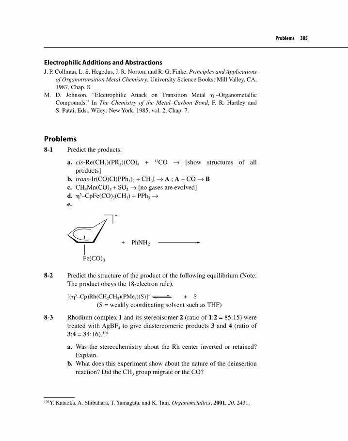
Problems 305
Electrophilic Additions and AbstractionsJ. P. Collman, L. S. Hegedus, J. R. Norton, and R. G. Finke, Principles and Applications
of Organotransition Metal Chemistry, University Science Books: Mill Valley, CA, 1987, Chap. 8.
M. D. Johnson, “Electrophilic Attack on Transition Metal η1–Organometallic Compounds,” In The Chemistry of the Metal–Carbon Bond, F. R. Hartley and S. Patai, Eds., Wiley: New York, 1985, vol. 2, Chap. 7.
Problems8-1 Predict the products.
a. cis-Re(CH3)(PR3)(CO)4 + 13CO → [show structures of all products]
b. trans-Ir(CO)Cl(PPh3)2 + CH3I → A ; A + CO → Bc. CH3Mn(CO)5 + SO2 → [no gases are evolved]d. η5–CpFe(CO)2(CH3) + PPh3 →e.
Fe(CO)3
+ PhNH2
8-2 Predict the structure of the product of the following equilibrium (Note: The product obeys the 18-electron rule).
[(η5–Cp)Rh(CH2CH3)(PMe3)(S)]+ + S (S = weakly coordinating solvent such as THF)
8-3 Rhodium complex 1 and its stereoisomer 2 (ratio of 1:2 = 85:15) were treated with AgBF4 to give diastereomeric products 3 and 4 (ratio of 3:4 = 84:16).104
a. Was the stereochemistry about the Rh center inverted or retained? Explain.
b. What does this experiment show about the nature of the deinsertion reaction? Did the CH3 group migrate or the CO?
104Y. Kataoka, A. Shibahara, T. Yamagata, and K. Tani, Organometallics, 2001, 20, 2431.
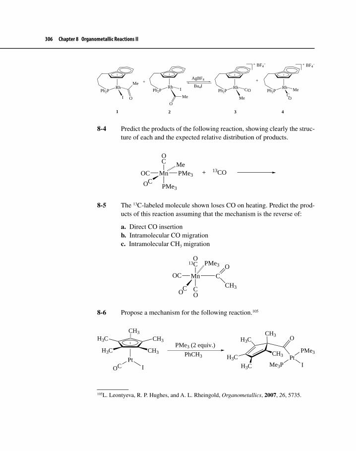
306 Chapter 8 Organometallic Reactions II
RhPh2P
I
Me
O
RhPh2P I Rh
Ph2P
Me
RhPh2P Me
CMe
O
C
BF4− BF4
−
++AgBF4
Bu4I
1 2 3 4
O
O
8-4 Predict the products of the following reaction, showing clearly the struc-ture of each and the expected relative distribution of products.
MnMe
C
C
PMe3
PMe3OC + 13CO
O
O
8-5 The 13C-labeled molecule shown loses CO on heating. Predict the prod-ucts of this reaction assuming that the mechanism is the reverse of:
a. Direct CO insertionb. Intramolecular CO migrationc. Intramolecular CH3 migration
Mn
PMe3
C
C
C
COC
CH3
O13
O
O O
8-6 Propose a mechanism for the following reaction.105
CH3
CH3
CH3
H3C
H3C
PtC I
PMe3 (2 equiv.)
PhCH3 PtPMe3
Me3P I
OCH3
CH3
H3C
H3C
H3C
O
105L. Leontyeva, R. P. Hughes, and A. L. Rheingold, Organometallics, 2007, 26, 5735.

Problems 307
8-7 Propose a mechanism for the following transformation.106
PPh2
Pt
PPh2 C
CH3
H2C=CH2
−80 oCPPh2
Pt
PPh2
O CH3
O
8-8 The complex [(η6–C6H6)Mn(CO)3]+ has carbonyl bands at 2026 and 2080 cm–1 and a single 1H NMR resonance at δ 6.90 ppm. This com-plex reacts with PBu3 to give product 5, which has infrared bands at 1950 and 2028 cm–1 and 1H NMR signals at δ 6.30 (relative area = 1),5.50 (2), 4.40 (1), 3.40 ppm (2), and signals corresponding to butyl groups. Complex 5 converts photochemically into 6, which has infrared bands at 1950 and 1997 cm–1 and only one signal, at δ 6.42 ppm, other than signals for the butyl groups. Suggest structures for 5 and 6.
8-9 Propose mechanisms for the two transformations shown.
a.
Mo CH2CH2CH2BrCCC
PPh3
Mo PPh3C
C
Br−
O
O
O O
O
O
b.
NHCH2Ph
OAc
PdL4
Et3NN
Ph
106C. S. Shultz, J. M. DeSimone, and M. Brookhart, J. Am. Chem. Soc., 2001, 123, 9172.

308 Chapter 8 Organometallic Reactions II
c.107
NMe
O
O
NMe
MeO
O
RuCp
RuCp
1) K2CO3
2) KO-t-Bu
3)
MeO S OMe
O
O
8-10 Consider the transformation shown below. When CH2Cl2 is the solvent, formation of 7 occurs exclusively. Use of toluene or diethyl ether as sol-vent results in a mixture of 7 and 8, with 7 usually predominating. The investigators postulated a mechanism for SO2 insertion that was different than the SE2 pathway discussed in Chapter 8.108
a. Propose an alternative step-wise mechanism for this reaction. [Hint: What positions on the Pd complex starting material are attractive for bonding with SO2?]
b. Why isn’t the SE2 mechanism a likely pathway for the formation of compound 7?
Pd
Me3P
Me3P
SO2
CH2Cl2
SO2PhMe or Et2O
Pd
SO
O
Me3P
Me3P
7
S
Pd
Me3P
Me3P
8
+ 7
OO
107F. C. Pigge, J. J. Coniglio, and S. Fang, Organometallics, 2002, 21, 4505.108J. Cámpora, J. A. López, P. Palma, D. del Rio, E. Carmona, P. Valerga, C. Graiff, and A. Tiripicchio, Inorg. Chem., 2001, 40, 4116.

Problems 309
8-11 Follow the step-wise reaction shown below. For each step, indicate what kind of fundamental organometallic reaction type is taking place.
PdX2L2 + CO Pd(CO)LX2
HO C C H
LX2Pd C O
C
C
H
O
O
OLX2Pd
H
H+
O
OLX2Pd
H
H
O
OH
HPdLX2 +
8-12 E-alkenes are more stable than their Z-isomers. When the (E)-3-hexene Ru complex 9 was treated with an excess of PPh3 or 4-substituted pyri-dines, the corresponding substituted complex 10 was produced as well as 3-hexene. If this were a simple ligand substitution, one would expect that only (E)–3-hexene would be released. Interestingly, both (E)- and (Z)-3-hexene were formed using the two types of nucleophiles. In fact, when 4-methoxypyridine was used as the nucleophile, the E/Z ratio was 13:87! Propose a mechanism that accounts for the formation of (Z)-3-hexene.109
Ru CC
L
L = PPh3, 4-picoline, 4-methoxypyridine
Ru CC
L
+ (Z)- and (E)-3-hexene
9 10
O O O O
8-13 Propose a mechanism for the following reaction.110
109K. M. McWilliams and R. J. Angelici, Organometallics, 2007, 26, 5111.110G. R. Hoel, R. A. Stockland, Jr., G. K. Anderson, F. T. Ladipo, J. Braddock-Wilking, N. P. Rath, and J. C. Mareque-Rivas, Organometallics, 1998, 17, 1155.

310 Chapter 8 Organometallic Reactions II
Pd
Me
ClPd
Cl
2
HH
C C
R R
Me
C C RR
R = CO2Me
8-14 Propose a mechanism for the following transformation [Hint: the mech-anism involves steps that are described in both Chapters 7 and 8.]111
RuPh3P
Ph3PC
CH2
PPh3
CH3CN/∆RuPh3P
PPh2
+ PPh3
8-15 Propose a mechanism for the following multi-step reaction that involves nucleophilic participation of a remote π bond. Assume that in the first step compound 11 acts as a nucleophile. [Fp = CpFe(CO)2; * = an arbitrary label to distinguish one Fp group from the other]
Fp+
Fp*Fp
Fp* +
Fp
Fp*
11
Fp*
Fp Fp*
Fp
111K. Onitsuka, M. Nishii, Y. Matsushima, and S. Takahashi, Organometallics, 2004, 23, 5630.

TWO
311
There are many reactions in chemistry that are favorable thermodynamically, yet they occur extremely slowly at room temperature. A few of these are shown in equations 9.1–9.3.
Water gas shift reaction:H2O (g) + CO (g) H2 (g) + CO2 (g)
9.1∆rGo = −6.9 kcal/mol
Alkene hydrogenation:CH3CH=CH2 (g) + H2 (g) CH3CH2CH3 (g)
9.2∆rGo = −20.6 kcal/mol
Glucose metabolism:C6H12O6 (glucose) + 6 O2 (g) 6 H2O (l) + 6 CO2 (g)
9.3∆rGo = −688 kcal/mol
The presence of a catalyst dramatically increases the rate of the reactions shown and countless others, even those that may not have negative free energies of reaction. Chapter 9 will consider the role transition metal complexes play as catalysts for several transformations, many of which are important industrially. As catalysts, transition metal complexes undergo most of the reactions we have just discussed in Chapters 7 and 8. We will encounter a number of different cata-lytic cycles in Chapter 9; other catalytic processes involving transition metals will be described in Chapters 11 and 12.
Homogeneous CatalysisThe Use of Transition Metal Complexes in Catalytic Cycles
NINE

312 Chapter 9 Homogeneous Catalysis
9-1 FUNDAMENTAL CONCEPTS OF HOMOGENEOUS CATALYSIS
The phenomenon of catalysis was recognized over 150 years ago by Berzelius, who referred to the “catalytic power of substances” that were able to “awake affinities that are asleep at this temperature by their mere presence and not by their own affinity.”1 Once the principles of thermodynamics were developed and the concept of equilibrium was established by the turn of the 20th century, scientists realized that catalysts are species that increase the rate of a reaction without affecting the equilibrium distribution of reactants and products. Exactly how catalysts are able to speed up reactions without changing the free energy of either reactants or products remained a mystery for many years. Only in the past few decades has it been possible to elucidate mechanistic pathways involving cat-alysts using such tools as kinetics, stereochemical studies, and spectroscopy. It is clear now that catalysts interact with reactants to provide a reaction pathway with a significantly lower free energy of activation than the corresponding uncatalyzed pathway. Figure 9-1 depicts this phenomenon, with the solid line representing the uncatalyzed reaction and the dashed line the catalyzed reaction path.
Typically, catalysts are intimately involved with reactants (often called substrates) in a cyclic series of associative (binding), bond making and/or break-ing, and dissociative steps (Scheme 9.1). During each cycle, the catalyst is regen-erated so that it may go through another cycle. Each cycle is called a turnover, and an effective catalyst may undergo hundreds, even thousands of turnovers before decomposing, with each cycle producing a molecule of product. The turnover number (abbreviated TON) is defined as the total number of reactant molecules a molecule of catalyst converts to product molecules. This is true if the catalyst is homogeneous and has one active site; if the catalyst has more than one active site, TON is calculated per active site. Turnover frequency (TOF) is the TON per unit time.2 In a stoichiometric reaction, on the other hand, the “catalyst” (actually reagent) undergoes only one turnover per molecule of product produced.
9-1-1 SelectivityThe laws of thermodynamics dictate that the product distribution resulting from a catalyzed or uncatalyzed reaction must be the same if enough time is allowed for the transformation to come to equilibrium. The presence of a catalyst, how-ever, can influence initial product distributions, allowing preferential forma-tion of a product that may be less stable thermodynamically than another. This
1Taken from a quotation in G. C. Bond, Homogeneous Catalysis, Oxford University Press: Oxford, 1987, p. 2.2For more information on TON and TOF, see G. P. Chiusoli and P. M. Maitlis, Eds., Metal Catalysis in Industrial Organic Processes, RSC Publishing: Cambridge, 2006, p. 270.

9-1 Fundamental Concepts of Homogeneous Catalysis 313
Figure 9-1Reaction Progress versus Energy Diagrams for a Catalyzed and Uncatalyzed Reaction
∆Gc
∆G
∆rGo
S+C
S-C
P-C
P+C
G
Reaction Progress
S: Substrate P: Product C: CatalystS-C: Substrate-Catalyst Complex P-C: Product-Catalyst Complex
is a phenomenon known as selectivity. There are several kinds of selectivity demonstrated by catalysts, such as chemoselectivity, regioselectivity, and ste-reoselectivity. Equation 9.4 illustrates an example of chemoselectivity, whereby hydrogenation occurs selectively at only one functional group in the reactant. In principle, hydrogenation could occur at the phenyl ring, the C=C bond, or the nitro group. In the presence of the Rh catalyst, however, H2 adds only to the alkene group.3
H2
(PPh3)3RhCl
NO2
O
O
NO2
O
O (80% yield)
9.4
3A. Jourdant, E. González-Zamora, and J. Zhu, J. Org. Chem., 2002, 67, 3163.

314 Chapter 9 Homogeneous Catalysis
The hydroformylation reaction (Section 9-2), shown in equation 9.5, demonstrates regioselectivity, whereby one regioisomer forms preferentially over another. The Co catalyst may be modified to increase the proportion of linear (anti-Markovnikov) over branched (Markovnikov) product.
R
CO/H2
HCo(CO)4 RC
H
OH
+
R
C
H
OH
major minor
9.5
The hydrogenation of disubstituted alkynes with Lindlar catalyst (equation 9.6) represents an example of the use of a stereoselective catalyst. Such catalysts promote the formation of one stereoisomer in preference to one or more oth-ers. In this particular example, the Z alkene is formed in great preference to the corresponding E isomer.
C C CH2CH3CH3CH2
H2
Pd/CaCO3/QuinolineC C
CH2CH3CH3CH2
H H
9.6
Scheme 9.1 A Schematic Picture of a Catalytic Cycle Showing C=C Bond Isomerization
LnM−H
L
Ln−1M−H
Starthere
H
Ln−1M
Ln−1M
Ln−1M
H
Ln−1M
Ligand associationLigand dissociation
β-Elimination 2,1-Insertion
1,2-Insertion
(Catalyst)

9-1 Fundamental Concepts of Homogeneous Catalysis 315
Catalysts also exhibit selectivity in their initial binding to reactants. Enzymes are well known for their ability to bind selectively to only one member of a pair of stereoisomers. The bound stereoisomer will undergo reaction, and the remain-ing isomer is inert to the reaction conditions. For example, the enantioselective addition of water to fumaric acid (the E isomer), which yields (S)-malic acid (equation 9.7), is catalyzed by an enzyme called fumarase. Isomeric maleic acid (the Z isomer) fails to react in the presence of fumarase.
C C
H
CO2HH
HO2CH2O
Fumarase
HO2CC
CH2−CO2H
HOH
(S)-Malic Acid
9.7
9-1-2 Homogeneous versus Heterogeneous CatalystsIn your study of chemistry thus far, you have probably encountered a number of catalyzed reactions. Those who are familiar with organic chemistry will recog-nize equation 9.2 as an alkene hydrogenation reaction that occurs at a reasonable rate only in the presence of a catalytic amount of Pd or Pt deposited on an inert solid. The synthesis of esters from alcohols and carboxylic acids (equation 9.8) is catalyzed by mineral acids such as H2SO4 or HCl.
COH
O
+ CH3CH2OHH+
COCH2CH3
O
+ H2O
9.8
The catalyst involved in the former reaction is known as a heterogeneous catalyst. Equation 9.8, on the other hand, demonstrates the use of a homogeneous catalyst. A heterogeneous catalyst exists as another phase in the reaction medium, typically as a solid in the presence of a liquid or gaseous solution of reactants. A homogeneous catalyst is dissolved in the reaction medium, along with the reac-tants. Homogeneous catalysts that are transition metal complexes find increasing importance in the chemical industry, where the use of heterogeneous catalysts has historically been predominant.4
4Despite the increasing use of homogeneous catalysts in the chemical industry, homogeneous catalysts are involved in processes that yield only about 15% of the total production of chemi-cals worldwide; J. Hagen, Industrial Catalysis: A Practical Approach, 2nd ed., Wiley–VCH Verlag: Weinheim, Germany, 2006, pp. 9 and 425.

316 Chapter 9 Homogeneous Catalysis
Table 9-1 summarizes the major differences between homogeneous and het-ereogeneous catalysts. The subsequent discussion assumes that the homogeneous catalysts being discussed contain transition metals.
Catalyst Composition and Nature of the Active SiteThe active sites on a heterogeneous catalyst are difficult to characterize because they are not discrete molecular entities. Instead, the active sites may be aggrega-tions of solid support material (e.g., silica gel or zeolites) coated with deposited metal atoms. Not all sites on the surface of the catalyst have the same activity and physical or chemical characteristics. Analytical techniques, such as Auger spec-troscopy and electron spectroscopy for chemical analysis, as well as scanning tunneling microscopy, have been applied in attempts to determine the nature of such catalytic surfaces. Much progress has been made, but much more informa-tion must be obtained before a complete and cogent understanding of heteroge-neous catalysis can emerge.
Homogeneous catalysts, on the other hand, are discrete molecules that are relatively easy to characterize by standard spectroscopic techniques, such as NMR, IR, etc. The active site consists of the metal center and adjoining ligands.
Determination of the Reaction MechanismBecause the constitution of the active site of a heterogeneous catalyst is difficult to determine, the elucidation of reaction mechanisms involving these catalysts can be troublesome indeed. The field of homogeneous catalysis, in contrast, has advanced rapidly over the past few decades because chemists have developed many techniques that are useful for studying reaction mechanisms. Elucidating the mechanism of a homogeneously-catalyzed reaction requires studying the mechanism of each individual step, in a series of relatively elementary chemical
Table 9-1 Major Differences between Homogeneous and Heterogeneous Catalysts
Characteristic Homogeneous Heterogeneous
1. Catalyst composition and nature of active site
Discrete molecules with well-defined active site
Nondiscrete molecular entities; active site not well defined
2. Determination of reaction mechanism
Relatively straightforward using standard techniques
Very difficult
3. Catalyst properties Easily modified, often highly selective, poor thermal stability, operates under mild reaction conditions
Difficult to modify, relatively unselective, thermally robust, operatesunder vigorous reaction conditions
4. Ease of separation from product Often difficult Relatively easy

9-1 Fundamental Concepts of Homogeneous Catalysis 317
reactions, by conventional methods. Each step must be shown to be kinetically and thermodynamically reasonable.5 Although this can be a daunting task for a reaction involving several catalytic steps, it is not at present as difficult as deter-mining exactly what goes on during a heterogeneous catalysis.
Catalyst Properties: Ease of Modification, Selectivity, Thermal Stability, and Reaction ConditionsBecause homogeneous catalysts are typically organotransition metal complexes, it is relatively easy to modify these compounds in order to increase selectivity. As we shall see, phosphines appear commonly as ligands in homogeneous catalysts. Phosphines offer a wide variety of stereoelectronic properties that can substan-tially influence the course of a catalyzed reaction.
Homogeneous catalysts are often much less thermally stable than their heterogeneous counterparts. The use of a homogeneous catalyst rather than a heterogeneous one requires milder conditions of temperature and pressure. If a sufficiently active homogeneous catalyst can be found that can do the job of a heterogeneous one, substantial savings in energy and initial capital cost (plants that run at high temperature and pressure are very expensive to build) accrue to the manufacturer that chooses to employ a homogeneously-catalyzed process.
Ease of Separation from Reaction ProductsHomogeneous catalysts suffer from one key disadvantage when compared with their heterogeneous counterparts. They are often quite difficult to separate from reaction products. Catalyst recovery is clearly important, not only in ensuring product purity but also in conserving often-used precious metals such as palladium and rhodium.
9-1-3 Enzymes: Homogeneous or Heterogeneous Catalysts?A discussion of catalysis would not be complete without a comparison of the catalysts we normally encounter in the laboratory or in industry with those that occur naturally (i.e., enzymes). Enzymes are proteins that are either soluble in the aqueous medium of the cell or attached to a cellular membrane. Soluble enzymes resemble homogeneous transition metal catalysts in ways other than their solubility characteristics. Enzymes have at least one region that serves as
5It should be pointed out that an individual step may be endothermic, even if the overall reaction is exothermic.

318 Chapter 9 Homogeneous Catalysis
an active site (see Figure 9-2) for substrate(s) to bind6 and thence to undergo transformation into product(s). Modification of the enzyme’s amino acid sequence can drastically alter the catalytic efficiency of the enzyme. Often, enzymes have sites remote from the active site where ligands other than substrate can bind. This binding can alter the nature of the active site by causing a conformational change in the structure of the protein. Binding at these remote sites may be a necessary precursor for catalytic activity. Similarly, transition metal complexes may change significantly in catalytic activity when modifications are made of ligands that are not directly involved in the overall chemical transformation (i.e., phosphines).
The active site of enzymes is not a discrete molecule, such as an organotran-sition metal complex, but instead is comprised of functional groups from several amino acids that are often positioned in the peptide chain rather distant from one another. These functional groups become neighboring only because of the folding of the polymeric chain of amino acids. Enzymes are large molecules that have a vast surface area compared with transition metal complexes and, as such, may have complex interactions with other cellular entities.
Membrane-bound enzymes loosely represent a hybrid between homogeneous and heterogeneous catalysts. The membrane represents a large surface area that supports catalytically active entities (the enzymes). The enzymes, however, are discrete molecules (although giant ones) in contrast to metal crystallites found in most heterogeneous catalysts.
Interestingly, one of the most active areas in transition metal catalysis concerns the use of a hybrid catalyst that resembles a membrane-bound enzyme. Much work has been reported in which transition metal complexes are bound to solid supports such as silica, alumina, or organic polymers. These catalytic systems have some of the advantages of both types of catalysts. Based on studies in homogeneous media, the transition metal complexes may be easily modified to increase selectivity. The complex, on the other hand, may be readily separated from product because it is bound to a solid support, a useful property indeed, as we discussed above. As promising as these hybrid catalysts are, however, their use in industry has not come to fruition. Such catalysts tend to suffer from “bleeding” of the active transi-tion metal away from the binding surface. Such bleeding lowers activity with time and is prohibitively costly if the active sites involve precious metals.
9-1-4 The Unique Fitness of the Transition MetalsAlthough many species serve as useful homogeneous catalysts (e.g., H+, OH–, Al3+, imidazole), complexes of transition metals are far and away the most selective.
6The binding energies involved in enzyme–substrate interactions are much less than ordinary chemical bonds. The cumulative effect, however, of several weak binding interactions is significant.

9-1 Fundamental Concepts of Homogeneous Catalysis 319
Figure 9-2 A Schematic View of the Mechanism of Chymotrypsin-Catalyzed Amide Hydrolysis Occurring at the Enzyme Active Site
O
O N N N
OHNH
O
NH
H
H
O
O N N
N
O
N
HO
NH
HHH
O
O N N
N
O
N
HO
NH2
H
O
O N N
N
O
N
HO
HHH
H
H
O
H
O
Enzyme
H
NH3+ + O
O
+ Enzyme
NH2
Asp102
His57
Ser195
Gly193

320 Chapter 9 Homogeneous Catalysis
Why is this so? The discussion in the next paragraphs attempts to shed some light on this very important question, in part by reminding readers of several concepts that we have already encountered.7
A Variety of Ligands Will Bind to Transition MetalsChapters 4–6 have shown that a host of different ligands will bind to metals and that these ligands may be classified as X- or L-type. In fact, transition metals will bind to virtually any other element in the periodic table and to almost all organic molecules. Ligands may either be directly involved in the catalytic pro-cess or indirectly affect catalysis by exerting steric and/or electronic effects on the complex.
Transition Metals Have the Ability to Bind to Ligands in a Number of WaysIn Chapters 4–6, we described how various ligands can bind to transition metals. The availability of d as well as s and p orbitals on the metal allows for the forma-tion of σ and π bonds from metal to ligand. A single ligand, such as an allyl group, may bind in an η1 or η3 manner, for example. The hapticity of such a ligand may change during a catalytic cycle, and the ease of this change facilitates ligand modification. Carbonyl ligands attach to a metal in a terminal or bridging bonding mode. Groups such as methyl or hydride may react as anionic, neutral (radical), or cationic species depending on the electron density of the metal. Finally, the strength of metal–ligand bonds is moderate (30–80 kcal/mol), allowing bonds between ligand and metal to form or break relatively easily—a necessity for the catalytic cycle to proceed.
A Variety of Oxidation States Is AvailableAs ligands are added to or removed from the metal by processes such as oxida-tive addition and reductive elimination, the oxidation state of the metal changes. Transition metals, with their d valence electrons, usually have a rather large num-ber of oxidation states available, particularly in comparison to main group metals. The elements in Groups 8–10 especially possess a tendency for rapid, reversible two-electron change (such as from 18 e– to 16 e– and back), and thus it is not surprising that they are often involved in homogeneous catalysis.
7An excellent discussion on the fitness of the transition metals for catalytic activity is found in C. Masters, Homogeneous Transition-Metal Catalysis—A Gentle Art, Chapman & Hall: London, 1981, pp. 5–20; see also J. Hagen, Industrial Catalysis: A Practical Approach, 2nd ed., Wiley–VCH Verlag: Weinheim, Germany, 2006, Chap. 2.

9-1 Fundamental Concepts of Homogeneous Catalysis 321
Transition Metal Complexes Exhibit Several Different GeometriesDepending on the coordination number, a variety of structural possibilities exists for transition metal complexes. Geometries such as square planar, octahedral, tet-rahedral, square pyramidal, and trigonal bipyramidal are common in complexes involving the transition metals. Much is already known about the behavior of ligands attached to metals in these geometries. For example, in square planar complexes, a ligand trans to another may cause the latter ligand to be quite labile and thus readily dissociate from the metal. If loss of the latter ligand is required for effective catalysis, then it is desirable to (1) design the catalytic cycle in such a way that a square planar complex is one of the intermediates along the path to the product and (2) have the directing group with a high trans effect positioned trans to the leaving group. Another example might involve a process where a key step is the reductive elimination of two ligands. We saw in Chapter 7 that RE requires the two leaving groups to be cis with respect to each other before the reaction may occur. The catalysis will be successful in this case if an intermediate forms readily, such that the two leaving groups are cis.
Transition metal complexes, with their well-defined geometries, serve as “templates” for the occurrence of reliable stereospecific or stereoselective ligand interaction. We know that alkyl migration to a carbonyl group occurs with retention of configuration at carbon, and that reductive elimination involves retention of configuration in the two leaving groups. In this way, transition metal complexes mimic the stereospecific reactions often catalyzed by enzymes.
Transition Metal Complexes Possess the “Correct” StabilityBy varying metal and ligands, transition metal complexes can be designed to serve as intermediates that are not too reactive or too unreactive. For a catalytic turn-over to occur, each intermediate in the cycle must be reactive enough to proceed to the next stage, yet not so reactive that other pathways (e.g., decomposition or a different bonding mode) become feasible.
We have just seen several reasons for the unique fitness of transition metals and their complexes as catalysts. The take-home lesson from all of this discussion is that the transition metals and the complexes derived from them are versatile. The stage is now set to examine several examples of homogeneous transition metal catalysis.
9-1-5 Catalysis and Green ChemistryWe have already made reference to green aspects of organometallic chemistry in Section 7-2-1, where environmentally-friendly characteristics of the activation of H−H, C−H, and C−C bonds were pointed out. In this section, we focus on the relationship between green chemistry and organometallic chemistry. Green chem-istry is defined as the “utilization of a set of principles that reduces or eliminates

322 Chapter 9 Homogeneous Catalysis
the use or generation of hazardous substances in the design, manufacture, and application of chemical products.”8 Among the 12 principles of green chemistry is the goal to maximize atom economy (i.e., to ensure that as many atoms of reac-tant as possible end up in the desired product). Other goals include reducing the use of hazardous materials; using renewable feedstocks for chemical processes (petroleum is not a renewable resource, at least in our lifetimes); using water as a solvent or using no solvent at all; producing useful, non-toxic, and biodegradable materials; and, most important for the discussion at hand, employing catalysts instead of stoichiometric reagents wherever possible.
Organotransition metal compounds play a key role in catalyzing “green” reactions and processes, especially when it comes to maximizing atom economy. The chemical industry has taken a lead role in promoting green chemistry, and we shall see examples of these developments in this and later chapters.
9-2 THE HYDROFORMYLATION REACTIONAmong all of the homogeneous processes catalyzed by transition metals, hydro-formylation stands out in three respects. It is the oldest process still in use today, it is responsible for producing the largest amount of material resulting from a homogeneous transition metal-catalyzed reaction,9 and it can be consid-ered a green process because it proceeds with almost 100% atom economy. The hydroformylation reaction was outlined already in equation 9.5.
Discovered in 1938 by Otto Roelen10 (of Ruhrchemie in Germany), cobalt-catalyzed hydroformylation (also known as the oxo11 reaction) was used successfully during World War II by the Germans to produce aldehydes from alkenes, H2, and CO. It was not until the mid 1950s, however, that hydroformy-lation became a large-scale industrial process worldwide. Two main factors then drove the production of hydroformylation-derived products: (1) the ready avail-ability of 1-alkenes from the petrochemical industry and (2) the large increase in production of plastics, which require plasticizing agents that are derived
8P. T. Anastas and J. C. Warner, Green Chemistry: Theory and Practice, Oxford University Press: New York, 1998, p. 11. This book is an excellent resource for those new to the field of green chemistry. 9In 2005, nearly 9.6 million metric tons (1 metric ton = 1000 kg or 1.1 U.S. tons) of hydro-formylation products were produced worldwide; S. Bizzari, M. Blagoev, and A. Kishi, “Oxo Chemicals,” in Chemical Economics Handbook, SRI Consulting: Menlo Park, CA, 2006.10O. Roelen, Ger. Patent, 849 548, 1938 O. Roelen, Angew. Chem., 1948, 60, 62; and J. Falbe, Carbon Monoxide in Organic Synthesis, Springer Verlag: New York, 1970.11The name oxo was given to the reaction because in German oxo means carbonyl, and carbonyl compounds (especially aldehydes) are the initial products of hydroformylation processes.

9-2 The Hydroformylation Reaction 323
from hydroformylation.12 Scheme 9.2 depicts some of the original applications of Co-catalyzed hydroformylation. Because of its economic importance and because it serves as a prototypical example of homogeneous transition metal catalysis, we will consider hydroformylation in more detail than some other catalytic processes that appear later in Chapter 9.
Propene is the most common feedstock for hydroformylation and is trans-formed into butanal and 2-methylpropanal, the former being the much more valuable product. Butanal may be hydrogenated in a separate step using a het-erogeneous catalyst to give 1-butanol, a useful solvent, or it may undergo aldol condensation followed by hydrogenation to give 2-ethyl-1-hexanol. The substi-tuted hexanol is used to make a diester of phthalic acid, which then serves as an agent (called a plasticizer) for making the normally rigid plastic, polyvinyl chloride (PVC), flexible.13 Hydroformylation converts C7–C9 alkenes to aldehydes
12C. Kohlpaintner, “Hydroformylation-Industrial,” in Encyclopedia of Catalysis, Vol 3, I. Horváth, Ed., Wiley: Hoboken, NJ, 2003, p. 787.13Tygon tubing, commonly used in laboratories, is an excellent example of plasticized PVC.
Scheme 9.2 Industrially Useful Compounds Produced by Hydroformylation
CO/H2
HCo(CO)4 H
OH
+H
OH
Propene:
C7−C9 Alkenes:
H2O
H
O
(via aldol condensation)
H2
OH
2-Ethyl-1-hexanol
CO/H2
HCo(CO)4
O
H
H21-Octanol
+H O
C11−C15 Alkenes:
CH3(CH2)10CH=CH2CO/H2
HCo(CO)3(PBu3)CH3(CH2)10CH2CH2CH2OH
OH
H2Ni or Pd cat.
Ni or Pd cat.

324 Chapter 9 Homogeneous Catalysis
containing one more carbon atom, which are then hydrogenated to give straight-chain alcohols, also useful as plasticizers. Alcohols containing 12 to 16 carbons result from hydroformylation–hydrogenation of corresponding alkenes with one less carbon atom. These alcohols serve as the basis for surfactant (detergent) compounds with several domestic and industrial uses.
9-2-1 Co-catalyzed HydroformylationScheme 9.3 illustrates the cycle of catalytic steps proposed by Heck and Breslow14 for cobalt-catalyzed hydroformylation. The mechanism they proposed
14R. F. Heck and D. S. Breslow, J. Am. Chem. Soc., 1961, 83, 4023.
Scheme 9.3 Heck–Breslow Mechanism for Hydroformylation
HCo(CO)3
Co(CO)3
H
Co(CO)4
CCo(CO)3
O
HCo(CO)4
CO
CO
H2
CH
O+
CH O
(minorproduct)
+
Co(CO)4
+Co(CO)3
C
O
1
2
4 or 5
7
8
a
b
cd
e
te
Starher

9-2 The Hydroformylation Reaction 325
resulted from studies on model organocobalt carbonyl complexes. The cycle shown is an excellent example of transition metal catalysis because it contains steps converting a precatalyst to the active complex, it consists of several sim-ple mono- and bimolecular steps involving the fundamental reactions of orga-nometallic chemistry, it demonstrates the validity of the 16- and 18-electron rules, and it shows intermediates with plausible geometries. It must be pointed out, however, that the mechanism for cobalt-catalyzed hydroformylation is not completely understood with regard to kinetic and thermodynamic parameters for each step.15 We will look at each step, commenting on its relation to the catalytic cycle and to material you have already encountered in this text, and we will also point out some of the more recent work aimed at elucidating the mechanism of hydroformylation.
Step aThe true catalytically-active species is probably HCo(CO)3, a 16-electron com-plex. This intermediate results from 18-electron HCo(CO)4, 1, which in turn ultimately comes from Co(0) or Co(II), via Co2(CO)8, in the presence of a 1:1 mixture of CO and H2 (synthesis gas).16 Sometimes 1 is prepared in a separate step and introduced to the alkene in the presence of synthesis gas; this allows the subsequent hydroformylation to be run at a lower temperature (90–120 oC rather than the usual 120–170 oC). The dissociation step to form the active catalyst occurs with a relatively high activation energy, and it is, of course, inhibited by a high concentration of CO (the overall rate law for hydroformylation typically shows the concentration of CO with a negative exponent, n, where 0 > n > −1). The reaction is run, however, under very high pressure (200–300 bar) to stabilize HCo(CO)3 and later intermediates in the catalytic cycle, thus demonstrating a balance in reaction conditions between the formation of sufficient HCo(CO)3 for hydroformylation to occur at a reasonable rate and the enhancement of the stabil-ity of catalytic intermediates.17 Calculations indicate that the preferred geometry
15For a recent summary of mechanistic work on Co-catalyzed hydroformylation, see P. W. N. M. van Leeuwen, Homogeneous Catalysis: Understanding the Art, Kluwer Academic: Dordrecht, The Netherlands, 2004, Chap. 7.16Mixtures of CO and H2 are called synthesis gas (sometimes referred to as “water gas”). Synthesis gas results from reaction of natural gas (or petroleum distillates) and steam over a nickel catalyst, and it is the basis for numerous organic molecules produced in large scale by the petrochemical industry.17For a good discussion of hydroformylation reaction conditions, see Footnotes 12 and 15 (Chapters 7 and 8); see also G. W. Parshall and S. D. Ittel, Homogeneous Catalysis, 2nd ed., John Wiley and Sons: New York, 1992, pp. 106–111, for a more concise treatment.

326 Chapter 9 Homogeneous Catalysis
for HCo(CO)3 is more likely to be 2 (loss of CO from an equatorial position) instead of 3 (loss of CO from an axial position).18
C Co CC
H
C
O
O
O
O
1
CoC
CH
C
O
O
O
2
C Co C
HC
OO
O
3
Step bThe next step involves binding of the alkene to 2, forming an 18-electron hydrido-alkene complex that can have several structures, two of which are shown as 4 and 5. Theoretical calculations at the DFT-B3LYP level19 by Jiao and co-workers demonstrated that Structure 4 is about 4 kcal/mol more stable than 5 (probably due to less steric hindrance), although only 5 has the requisite geometry (Co, H, and the double bond carbon atoms all coplanar) for a direct 1,2-insertion step (step c).20 Overall, therefore, steps a and b constitute a ligand substitution via a D mechanism.
CoC
CH
C
C
C
H
CH3
H
HO
OO
4
CoC
CH
C
O
OO
C
C
H CH3
H H
5
18(a) T. Ziegler and L. Versluis, “The Tricarbonylhydridocobalt-Based Hydroformylation Reaction,” in Homogeneous Transition Metal Catalyzed Reactions, W. R. Moser and D. W. Slocum, Eds., American Chemical Society: Washington, D.C., 1992, pp. 75–93, and references therein. (b) For a recent study reaching a similar conclusion to Ziegler but still refining the structures of 2 and 3, see C.-F. Huo, Y.-W. Li, G.-S. Wu, M. Bellar, and H. Jiao, J. Phys. Chem. A, 2002, 106, 12161.19C.-F. Huo, Y.-W. Li, M. Beller, and H. Jiao, Organometallics, 2003, 22, 4665.20See Footnotes 18a and 19.

9-2 The Hydroformylation Reaction 327
Step cOnce complexation of the alkenes occurs, 1,2-insertion is facile and reversible. Insertion gives initially a 16-electron complex, 6, which shows an agostic hydro-gen. The high concentration of CO quickly drives step c to completion, resulting in 18-electron intermediate 7. Structures 6 and 7 show the result of “anti-Markovnikov” insertion from which the linear aldehyde, rather than the branched isomer, will result.
It is this exothermic step that probably is the source of the preference for linear hydroformylation products over branched ones. The structure of the com-parable 18-electron branched intermediate 7′ is about 2 kcal/mol less stable than 7, according to Jiao’s calculations. This difference leads ultimately to the anti-Markovnikov, linear aldehyde over the branched-chain isomer. Although β-elimination is possible now, the high partial pressure of CO present in the reac-tion vessel tends to stabilize 7 and prevent loss of CO that would generate the vacant site necessary for elimination to occur.
CoC
C
H2C
C
O
O
O
CH
CH3
H
6
CoC
C
C
O
O
O
CO
CH2H2C
CH3
7
CoC
C
C
O
O
O
CO
C CH3
CH3H
7'
Step dStep d involves CO insertion, which really is, as we saw in Chapter 8, a 1,2-migration of the alkyl group to CO (equation 9.9). Calculations indicate that the rearrangement has a low activation energy and is endothermic.21 Under the reac-tion conditions of high CO partial pressure, the 16-electron alkyl η2–carbonyl complex (8) must reversibly add CO to form (RCO)Co(CO)4, which is the only detectable intermediate observed when the reaction has been followed using IR spectroscopy.22 The stage is now set for the addition of hydrogen to give the alde-hyde mixture as the final products of the catalytic cycle.
21See Footnote 19.22R. J. Whyman, J. Organomet. Chem., 1974, 66, C23, and 1974, 81, 97.

328 Chapter 9 Homogeneous Catalysis
CoC
C
C
O
O
O
CO
CH2H2C
CH3
7
CoC
C
C
O
O
O
O
8
C
CH2
CH2
CH3
9.9
Step eTwo pathways have been proposed for step e, which may be the rate-limiting stage in the cycle (this notion is supported by the observed overall rate law for hydroformylation, which is typically first-order in H2 concentration). Equation 9.10 illustrates an oxidative addition followed by reductive elimination sequence, as originally proposed. Since Heck and Breslow’s work, a bimolecular process described by equation 9.11 has been suggested.23
CoC
C
C
O
O
O
O
8
C
CH2
CH2
CH3
CoC
C H
H
C
C
O
O
O
O
H2
CH
O
+
HCo(CO)3
9
9.10
CH
O
8 + HCo(CO)4 Co2(CO)7H2
HCo(CO)3 + HCo(CO)4
9.11
Although the bimolecular process involving reaction of the acylcobalt com-plex with HCo(CO)4 occurs readily under stoichiometric conditions, the low
23N. H. Alemaroglu, J. M. L. Renninger, and E. Oltay, Monatsh. Chem., 1976, 107, 1043.

9-2 The Hydroformylation Reaction 329
concentration of the two required cobalt complexes under catalytic conditions probably argues against the process shown in equation 9.11 as a catalytic step. It has also been shown using IR spectroscopy that, under normal catalytic conditions in the presence of a mixture of D2/H2, H2 is the main source of hydro-gen in the aldehyde RE step, even in the presence of a high concentration of HCo(CO)4.24
Whether the OA–RE process occurs (equation 9.10) in the usual manner is still a matter of question because calculations indicate that a direct process involving the addition of H2 to 8 to give dihydride 9 occurs with a rather high activation energy. A lower-energy process seems to be possible according to most recent calculations if an η2–dihydrogen complex (10, equation 9.12), forms instead. Once 10 forms, bond rotation about the Co−C (carbonyl) bond occurs, followed by conversion of the η2–H2 complex into dihydride 11. Complex 11 then undergoes exothermic RE to give HCo(CO)3 and linear aldehyde predominantly.25 The detailed experimental verification of theoretical calculations for step e awaits further investigation.
CoC
C H
H
C
C
O
O
O
10
8H2
CoC
C
C
C
O
O
O
O
CH
O
+
HCo(CO)3
H
H
11
O
9.12
The original hydroformylation process described above is still used, espe-cially for the production of aldehydes and alcohols derived from alkenes with more than four carbon atoms. The process, however, is not without problems in actual practice. Some of these problems include the following.
1. The ratio of linear to branched aldehydes is at best only ca. 4 to 1, and because the linear isomer is far more valuable than its branched coprod-uct, improvement in this regard would be important from an economic standpoint.
2. The active catalyst is unstable, and its separation and recovery are difficult.3. The high partial pressure of CO required for the process means that plants
are expensive to build and operate.
24P. Pino, A. Major, F. Spindler, R. Tannenbaum, G. Bor, and I. T. Horváth, J. Organomet. Chem., 1991, 417, 65.25See Footnote 19 and references therein.

330 Chapter 9 Homogeneous Catalysis
9-2-2 Phosphine-Modified HydroformylationIn 1968, Slaugh and Mullineaux26 (Shell Oil Company) reported that adding tertiary phosphines, such as PBu3 or the bicylo tertiary phosphine 12 (used because this ligand confers thermal stability to the catalyst, allowing the catalyst to be heated to a higher temperature than is possible with PBu3), resulted in hydroformylation taking place at less than 100 bar (vs. the 200–300 bar nor-mally required). Although the phosphine-modified catalyst was not as active as HCo(CO)3 toward hydroformylation, it was a better hydrogenation catalyst. Thus, the two stages of hydroformylation and hydrogenation could be combined into one step (using a ratio of H2/CO = 2:1). The ratio of linear to branched product, moreover, was as high as 9 to 1. Finally, because the modified catalyst, HCo(CO)3(PR3), turned out to be more stable than the original, it was easier to separate it from product alcohols. The advantages of the Shell process are diminished somewhat because hydroformylation must occur at a higher tem-perature (160–200 oC) and some alkene (ca. 15%) is converted directly to the corresponding alkane, owing to the effectiveness of the catalyst in promoting hydrogenation.
PCH2(CH2)18CH3
12
The higher selectivity of the modified catalyst in producing anti-Markovnikov product versus branched probably is due mainly to steric factors. The large steric bulk of PBu3 or phosphine 12 (compared with that of CO), as measured by its cone angle (see Section 6-3), must influence the course of the insertion of the alkene into the Co−H bond as shown in transition state structures 13 and 14. Structure 13 illustrates the occurrence of 1,2-insertion that would lead ultimately to linear aldehyde or alcohol. The phosphine ligand points away from the R group on the alkene. Much more steric hindrance occurs with the other orientation, shown by 14, in which the R group and the phosphine are on the same side of the structure.
26L. H. Slaugh and R. D. Mullineaux, J. Organomet. Chem., 1968, 13, 469 and L. H. Slaugh and R. D. Mullineaux (to Shell Oil Company), U. S. Patents 3,239,569 and 3,239,570, 1966.

9-2 The Hydroformylation Reaction 331
CoC
Bu3P
H
CO
O
C
C
RH
H
H
13
CoC
Bu3P
H
CO
O
C
C
HH
H
R
14
Studies with a variety of phosphine ligands have indicated that electronic factors may also play a role in the rate and orientation of phosphine-modified hydroformylation. As σ-donors, phosphines (possessing low χ values; see Section 6-3 for a discussion on χ values) undoubtedly donate electron density to the Co center that can then be taken up by the CO ligands, thus providing overall stability to the catalyst complex.27 Investigations of phosphine-modified hydroformylation have attempted to identify key intermediates in the catalytic cycle. Instead of acyl- and alkylcobalt complexes typical of the unmodified pro-cess, only phosphine-substituted cobalt carbonyl species have been observed.28 We can only assume that the steps in the catalytic cycle are analogous to those for the unmodified process (Scheme 9.3), with the first step consisting of loss of a CO ligand, but that the rate-determining step occurs at a different stage, perhaps during alkene complexation.29 The Shell process and related phosphine-modified hydroformylations continue to be used in industry on a large scale to produce C12–C16 detergent alcohols.
9-2-3 Rhodium-Catalyzed HydroformylationMonodentate LigandsAs the development of suitable cobalt hydroformylation catalysts occurred, work was also carried out to create corresponding Rh complexes that could also serve as suitable catalysts. Under appropriate conditions in the presence of H2 and CO, HRh(CO)4 forms from Rh–carbonyl cluster compounds. The hydrido–Rh
27For a good discussion of the modified hydroformylation process including an analysis of phosphine ligand effects, see C. Masters, Homogeneous Transition-Metal Catalysis—A Gentle Art, Chapman & Hall: London, 1981, pp. 114–120.28F. Piacenti, M. Bianchi, and M. Bendetti, Chim. Ind. Milan, 1969, 49, 245.29For a recent review on high-pressure NMR studies of phosphine-modified, Co-catalyzed hydroformylation, see C. Dwyer, H. Assumption, J. Coetzee, C. Crause, L. Damoense, and M. Kirk, Coord. Chem. Rev., 2004, 248, 653.

332 Chapter 9 Homogeneous Catalysis
complex catalyzes hydroformylation, but it also serves as a good alkene hydrogenation catalyst. Ratios of linear to branched hydroformylation products tend to be low also. Several groups30 discovered in the 1960s that the addition of phosphines allowed hydroformylation to occur, even at atmospheric pressure and at relatively low temperature. With the appropriate phosphine and by adjusting other reaction parameters, high linear-to-branched aldehyde product ratios were achieved without extensive hydrogenation of either the alkene starting material or the aldehyde (to give alcohol). In 1976, Union Carbide first commercialized the use of phosphine-modified rhodium catalysts in hydroformylation.
Rhodium–phosphine catalysts offer many advantages over cobalt systems. Rhodium complexes are 100 to 1000 times more active than Co complexes, so much less rhodium needs to be present in the reactor.31 The pressure (15–25 bar) and temperature (80–120 oC) required for reaction are significantly lower than for either Co-based process, meaning that initial costs for plant construction are rela-tively low, as are energy expenses to keep the plant running. If the hydrocarbon starting material consists of only 1-alkenes, linear-to-branched aldehyde product ratios as high as 15 to 1 are obtained. Despite the need to carefully recover expen-sive catalyst, rhodium–phosphine-catalyzed hydroformylation is clearly the opti-mal process if linear aldehydes are the desired products. If alcohols are the goal, then using a phosphine-modified Co catalyst is preferred because hydroformyla-tion and hydrogenation occur in the same reaction vessel.32
Scheme 9.4 illustrates the steps involved in the phosphine–rhodium catalytic cycle. The immediate precursor to the active species is either HRh(CO)2(PR3)2 or HRh(CO)(PR3)3
33 depending on the concentration of CO with respect to phosphine.
In contrast to PBu3, used in the phosphine-modified Co process, the optimal phosphine for Rh-based catalysis appears to be PPh3 or a similar aryl phosphine. PBu3 is apparently too effective at donating electron density to the metal in the case of Rh, and the intermediate catalytic species are too stable for effective catalysis.
30J. A. Osborne, J. F. Young, and G. Wilkinson, J. Chem. Soc., Chem. Commun., 1965, 17; C. K. Brown and G. Wilkinson, J. Chem. Soc. A, 1970, 2753; R. L. Pruett and J. A. Smith, J. Org. Chem., 1969, 34, 327; and L. H. Slaugh and R. D. Mullineaux, U.S. Patent 3,239,566, 1966.31This is fortunate, because the cost per gram of Rh is over 1000 times higher than that of Co.32C. Masters, Homogeneous Transition-Metal Catalysis—A Gentle Art, Chapman & Hall: London, 1981, pp. 127–128.33It is interesting to note that HRh(CO)(PR3)3 is an efficient alkene hydrogenation catalyst. It also resembles the very effective hydrogenation catalyst, ClRh(PPh3)3 (Wilkinson’s catalyst, Section 9-4-2). Apparently, when the partial pressure of CO exceeds 10 bar, the capability of the complex to hydrogenate alkenes is suppressed.

9-2 The Hydroformylation Reaction 333
The triaryl phosphine seems to have the right combination of steric (to induce the formation of linear product at the 1,2-insertion stage) and electronic (to donate electron density to metal in order to stabilize CO ligands) properties. Studies indi-cate that the rate-determining step is likely to be hydrogenation of the acylrhodium intermediate (as with unmodified Co hydroformylation), but the mechanism of this apparent OA–RE step is not completely understood.34 DFT-level theoretical studies have suggested that the selection for linear versus branched aldehydes
34M. Garland and P. Pino, Organometallics, 1991, 10, 1693; J. H. Feng and M. Garland, Organometallics, 1999, 18, 417; G. Liu, R. Volken, and M. Garland, Organometallics, 1999, 18, 3429; and A. Oswald, D. E. Hendriksen, R. V. Kastrup, and E. J. Mozeleski, “Electronic Effects on the Synthesis, Structure, Reactivity, and Selectivity of Rhodium Hydroformylation Catalysts,” in Homogeneous Transition Metal Catalyzed Reactions, W. R. Moser and D. W. Slocum, Eds., American Chemical Society: Washington, D.C., 1992, pp. 395–417.
Scheme 9.4 Catalytic Cycle for Phosphine-Modified, Rh-Catalyzed Hydroformylation
HRh(CO)2L2
CO
RC
H
O
RhC
L H
LO
L Rh L
H
CO
R
RhC
L
LO
R
CORhL
L
CO
R
RhC
L C
LO
R
O
RhL
L
C
CO
H
H
R
O
RhC
L
LO
R
(Leads tobranchedproduct)
L = PPh3
CO
Starthere

334 Chapter 9 Homogeneous Catalysis
occurs early in the catalytic cycle during the alkene complexation and insertion stages.35
In the 1980s, Ruhr Chemie (now Celanese) and Rhone–Poulenc developed a now well-established Rh-catalyzed formylation involving a highly water-sol-uble Rh–phosphine complex where the aryl substituents of the phosphine were substituted with sulfonic acid groups at the meta-position, giving a ligand known as triphenylphosphinetrisulfonate, or tppts (structure 15).36 A two-stage process is involved, which is run under mild conditions at 18 bar and 85–90 oC, where the catalyst remains in the aqueous phase and the aldehyde product goes to the organic phase, where it may be easily separated. One major advantage of the two-phase reaction, in addition to producing a high linear-to-branched product ratio under mild conditions, is that catalyst loss is minimal. In contrast to a single-stage process, where a catalyst separation operation is necessary, the two-stage process finds the catalyst already separated from the product as it forms. The initial lack of solubility of alkenes—especially C5 and above—in the aqueous phase, how-ever, limits the two-phase process to hydroformylation of low-molecular-weight alkenes such as propene and 1-butene.
P
15
SO3−
−O3S
−O3S
35M. Sparta, K. J. Børve, and V. R. Jensen, J. Am. Chem. Soc., 2007, 129, 8487 and refer-ences therein.36E. Kuntz, CHEMTECH, 1987, 17, 570 and P. W. N. M. van Leeuwen, Homogeneous Catalysis: Understanding the Art, Kluwer Academic: Dordrecht, The Netherlands, 2004, pp. 150–152.
Exercise 9-1 Increasing the concentration of phosphine in the phosphine–rhodium cycle slows the reaction rate, but it also raises the linear/branched product ratio. Explain.

9-2 The Hydroformylation Reaction 335
Bidentate LigandsOver the past 20 years, much research on Rh-catalyzed hydroformylation has focused on the use of bidentate phosphine and phospite ligands. The presence of such ligands often results in high ratios of linear to branched aldehydes. In addi-tion to the cone angle and electronic factor χ, there is another parameter associ-ated with bidentate ligands called the bite angle. Casey and Whiteker37 were the first to define a concept known as the natural bite angle (βn), which is the P−M−P bond angle (Structure 16) determined from molecular mechanics calculations (see Section 2-4).38
L2P
M
PL2
(bridging backbone)
βn
16
There is potential for error in these calculations, because the value of βn for a particular ligand will vary as a function of the metal and the force field used in the molecular mechanics calculation. As long as the metal atom remains con-stant and the same force field is used for the calculation, the values of βn for a series of related bidentate phosphines and phosphites are self-consistent within the series.
One of the first-reported bidentate ligands that resulted in significant enhance-ment of the ratio of linear to branched aldehyde was 2,2′-bis[(diphenylphosphino)methyl]-1,1′-biphenyl, which is abbreviated BISBI (structure 17).39
37C. P. Casey and G. T. Whiteker, Isr. J. Chem., 1990, 30, 299.38Crystal structures of diphosphine–metal complexes may show bite angles that are differ-ent than βn, so the calculation of βn has built in with it the possibility of some flexibility in bond angle as long as the change in bite angle does not result in an increase of more than 3 kcal/mol of strain energy. See Footnote 37 and P. W. N. M. van Leeuwen, Homogeneous Catalysis: Understanding the Art, Kluwer Academic: Dordrecht, The Netherlands, 2004, pp. 16–19, and 153–166 for additional discussion of βn.39T. J. Devon, G. W. Phillips, T. A. Puckett, J. L. Stavinoha, and J. J. Vanderbilt (to Texas-Eastman), U.S. Patent 4,694,109, 1987.

336 Chapter 9 Homogeneous Catalysis
PPh2
PPh2
17
Casey observed a linear/branched ratio of 66:1 using a BISBI–Rh complex to hydroformylate 1-hexene. This is a huge increase over the linear/branched ratio of only 2.6, which Casey observed when a Rh–dppe40 complex is used for hydro-formylation of 1-alkenes.41 The βn of BISBI is 113–120o, whereas that of dppe is much lower, at 85o.
One explanation for the regioselectivity is related to the stereochemistry of the diphosphine–Rh catalyst complexed with the alkene. We have seen ear-lier that high linear-to-branch ratios in Rh-catalyzed hydroformylation, as with Co-catalyzed hydroformylation, stem from the alkene complexation–insertion step of the catalytic cycle, so differences in steric and electronic factors as a func-tion of stereochemistry could play a significant role in the regiochemical result of the reaction. There are two trigonal bipyramidal possibilities for the diphosphine–Rh–alkene complex, which are denoted a–e (apical–equatorial isomer 18) and e–e (diequatorial isomer 19).
RhPPh2
Ph2P
H
C
Y
O
R
Y = Bridging backbone
RhPh2P
CH
PPh2
Y
OR
18 (a-e) 19 (e-e)
Studies have shown that when βn is large, the bidentate ligand tends to bind with e–e stereochemistry. Because the bond angle described by two equatorial ligands in a trigonal bipyramid is expected to be 120o, e–e stereochemistry ought
40Another abbreviation for dppe is DIPHOS.41C. P. Casey, G. T. Whiteker, M. G. Melville, L. M. Petrovich, J. A. Garvey, Jr., and D. R. Powell, J. Am. Chem. Soc., 1992, 114, 5535.

9-2 The Hydroformylation Reaction 337
to be more feasible with ligands with large values of βn. On the other hand, the bond angle expected when two ligands are a–e with respect to each other is 90o, so bidentate ligands with βn values around 90o would tend to bond in that manner. Researchers have suggested that e–e bisphosphine complexes introduce more steric congestion than corresponding a–e complexes. This congestion, therefore, favors the transition state and product that are less congested, which are those associated with the pathway to produce linear aldehyde. A series of diphosphine ligands, one of which is shown in structure 20, was synthesized by van Leeuwen.42 He observed that there was a strong correlation between a high value of βn and a high linear-to-branched ratio, which lends support to the hypothesis that the more the catalyst–alkene complex exists as the e–-e ste-reoisomer, the higher the likelihood of the formation of linear over branched aldehyde.
O
PPh2 PPh2
20
At this time, however, there is still work to be done to completely under-stand the influence of βn on the regiochemistry of Rh-catalyzed hydroformyla-tion. For example, studies have demonstrated that electronic factors also play a key role in determining linear-to-branched ratio with substituted DIPHOS ligands, such as 21, showing a clear preference for linear product when the electron-withdrawing phosphine resided in the equatorial position and the electron-rich phosphine in the apical position of a trigonal bipyramidal Rh complex.43
42M. Kranenburg, Y. E. M. van der Burgt, P. C. J. Kramer, and P. W. N. M. van Leeuwen, Organometallics, 1995, 14, 3081; L. A. van der Veen, M. D. K. Boele, F. R. Bregman, P. C. J. Kramer, P. W. N. M. van Leeuwen, K. Goubitz, J. Fraanje, H. Schenk, and C. Bo, J. Am. Chem. Soc., 1998, 120, 11616; and L. A. van der Veen, P. H. Keeven, G. C. Schoemaker, J. N. H. Reek, P. C. J. Kramer, P. W. N. M. van Leeuwen, M. Lutz, and A. L. Spek, Organometallics, 2000, 19, 872.43C. P. Casey, E. L. Paulsen, E. W. Beuttenmueller, B. R. Proft, B. A. Matter, and D. R. Powell, J. Am. Chem. Soc., 1999, 121, 63.
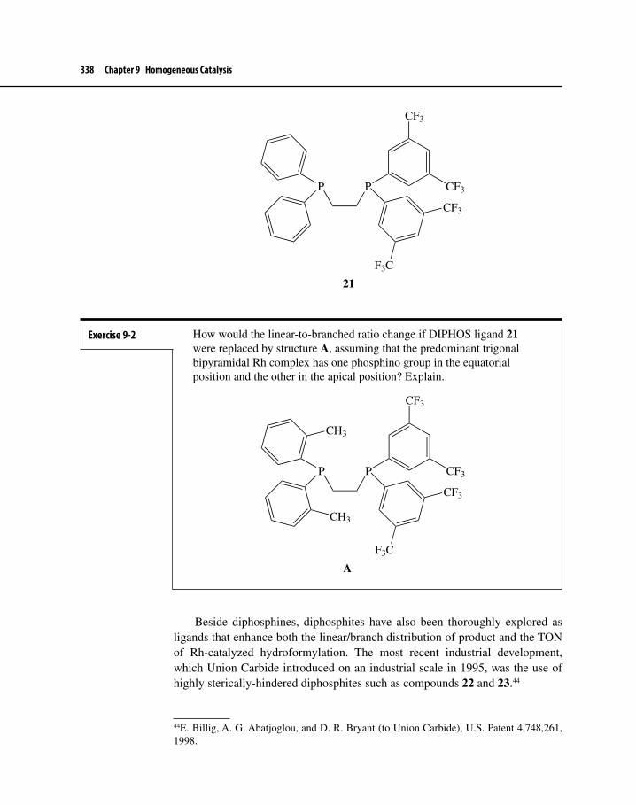
338 Chapter 9 Homogeneous Catalysis
P P
CF3
CF3
CF3
F3C
21
Beside diphosphines, diphosphites have also been thoroughly explored as ligands that enhance both the linear/branch distribution of product and the TON of Rh-catalyzed hydroformylation. The most recent industrial development, which Union Carbide introduced on an industrial scale in 1995, was the use of highly sterically-hindered diphosphites such as compounds 22 and 23.44
44E. Billig, A. G. Abatjoglou, and D. R. Bryant (to Union Carbide), U.S. Patent 4,748,261, 1998.
Exercise 9-2 How would the linear-to-branched ratio change if DIPHOS ligand 21 were replaced by structure A, assuming that the predominant trigonal bipyramidal Rh complex has one phosphino group in the equatorial position and the other in the apical position? Explain.
P P
CF3
CF3
CF3
F3C
A
CH3
CH3

9-2 The Hydroformylation Reaction 339
These ligands allow hydroformylation of propene to occur at 100 oC and less than 20 bar, resulting in a linear/branched ratio of 30:1 and a 98% conversion of pro-pene to product in one pass over the catalyst—truly an impressive achievement.
9-2-4 Other Aspects of HydroformylationOther metals may serve as the basis for hydroformylation catalysts. The overall effectiveness of these metals compared with Co and Rh is as follows.45
Rh > Co > Ir > Ru > Os > Mn > Fe > Cr, Mo, W, Ni, Re Rel. Reactivity: 104–103 1 10–1 10–2 10–3 10–4 10–6 < 10–6
Investigations of mechanistic steps in hydroformylation cycles and the effects of ligands continue to be an active area of interest for organometallic chemists. Later in Chapter 9 there will be an example of the use of hydroformylation in the green synthesis of a popular drug. The use of chiral diphosphine and diphosphite ligands for hydroformylation also shows promise for producing enantioenriched chiral aldehydes (section 12–3–1).
45K.-D. Wiese and D. Obst, Top. Organomet. Chem., 2006, 18, 1.
OMeMeO
O O
P(OAr)2P
OO
t-Bu
OMe
t-Bu
MeO
t-But-Bu
(OAr)2 =O O
22
OMeMeO
O O
P
O
O
t-But-Bu
P O
O
23

340 Chapter 9 Homogeneous Catalysis
9-3 THE WACKER–SMIDT SYNTHESIS OF ACETALDEHYDEEthanal (more commonly known as acetaldehyde) is another aldehyde of commercial importance. Oxidation to acetic acid and possible subsequent dehydra-tion to form acetic anhydride are the typical fates of this compound. Acetaldehyde was originally prepared by hydration of acetylene according to equation 9.13, a facile and high-yield route. This synthesis is now obsolete because of problems associated with the starting material, acetylene. Acetylene must be produced by heating a hydrocarbon gas stream to high temperature, sometimes in the pres-ence of an electric arc. All processes for producing it require large amounts of energy. Acetylene is also thermodynamically unstable, and it must be handled with extreme care to prevent explosion.
HC CH + H2OH+
Hg(II)H2C=CHOH CH3 C
O
H
9.13
The incentive, therefore, existed to develop a process for producing acetalde-hyde from a cheaper and less hazardous starting material. It had long been known that acetaldehyde formed directly from ethylene and water in the presence of a stoichiometric amount of PdCl2, according to equation 9.14.46 It was not until the 1950s, however, that a commercially-feasible process was developed by Smidt at Wacker Chemie in Germany.47 The Wacker–Smidt synthesis of acetaldehyde combines equation 9.14 with steps shown in equations 9.15 and 9.16. This allows deployment of Pd in catalytic amount because much less expensive reagents—CuCl2, HCl, and O2—are used to keep Pd in the proper oxidation state.
CH3 C
O
H
CH2=CH2 + PdCl2 + H2O + Pd(0) + 2 HCl
9.14
Pd(0) + 2 CuCl2 PdCl2 + 2 CuCl 9.15
2 CuCl + 2 HCl + 1/2 O2 2 CuCl2 + H2O
CH2=CH2 + 1/2 O2 CH3 C
O
H
9.16
46F. C. Phillips, J. Am Chem. Soc., 1894, 16, 255.47J. Smidt, W. Hafner, R. Jira, J. Sedlmeier, R. Sieber, R. Rütlinger, and H. Kojer, Angew. Chem., 1959, 71, 176 and J. Smidt, W. Hafner, R. Jira, R. Sieber , J. Sedlmeier, and S. Sabel, Angew. Chem. Internat. Edit. Engl., 1962, 1, 80.

9-3 The Wacker–Smidt Synthesis of Acetaldehyde 341
The overall reaction is equivalent to direct oxidation of ethylene by O2. The process is run in one or two stages depending on whether the catalyst is regenerated in situ or in a separate reactor. The former process uses pure oxygen in the presence of ethylene, Pd(II), CuCl2, and HCl. The latter process uses the chemistry described in equation 9.14 in one reactor and that described in equations 9.15 and 9.16 in another separate reaction vessel. Both processes have their advantages and dis-advantages and both were used commercially in the United States and Europe, producing acetaldehyde at about the same production cost. In terms of the amount of product produced, the Wacker–Smidt process represents an economically sig-nificant example of the use of transition metal homogeneous catalysis. The tech-nology also has been used to produce vinyl acetate (equation 9.17), a monomer that is subsequently polymerized to give polyvinylacetate films.48
CH2=CH2 + Cu(OAc)2 + KCl + KOAcO2
PdCl2CH2=CH−OAc + H2O
9.17
The Wacker–Smidt process—hereafter known simply as the Wacker oxida-tion, reaction, or process—enjoyed considerable success, yet its use has declined dramatically over the past 10 years for at least two reasons.49 First, manufacturing plants are expensive to build and maintain because they must be constructed to withstand a corrosive environment. Second, another procedure that yields acetic acid directly from synthesis gas was developed and now supplants the Wacker–Smidt process. This newer route also uses homogeneous catalysis involving Rh and Ir complexes and will be described in Section 9-5.
Although the Pd(II)-catalyzed route to acetaldehyde is no longer important to the chemical industry, the mechanistic basis of the process is interesting because it involves a number of fundamental kinds of organometallic reactions, such as ligand substitution, nucleophilic attack at a π ligand, and 1,2-insertion. The quest for under-standing the details of the catalytic mechanism has been extensive, and it has uncov-ered much useful information concerning not only the Wacker oxidation but also other organopalladium reactions. Moreover, the chemistry of the Wacker process has been adapted by synthesis chemists to convert terminal alkenes to methyl ketones.50
48For a good discussion of the Wacker–Smidt and related processes, see P. Wiseman, An Introduction to Industrial Organic Chemistry, Wiley: New York, 1976, pp. 97–103. A pro-cess using palladium-impregnated silica, developed later, is superior to the homogeneously-catalyzed process described in equation 9.17.49Acetaldehyde production via the Wacker process in North America has ceased; only China remains as a significant producer of this compound, presumably using, at least in part, the Wacker process (S. M. Malveda, K. Fujita, and B. Suresh, “Acetaldehyde,” in Chemical Economics Handbook, SRI Consulting: Menlo Park, CA, 2007).50For good reviews on the use of Wacker oxidation in organic synthesis, see J. M. Takacs and X.-T. Jiang, Curr. Org. Chem., 2003, 7, 369 and C. N. Cornell and M. S. Sigman, Inorg. Chem., 2007, 46, 1903.

342 Chapter 9 Homogeneous Catalysis
Scheme 9.5 illustrates an outline of the catalytic cycle involving organopal-ladium complexes. It also shows how Cu(II) and O2 couple with the Pd cycle to regenerate Pd(II). The scheme is consistent with the rate law51 observed for Wacker–Smidt oxidation:
k[CH2=CH2][PdCl42–]
Rate = ——————————[H+][Cl–]2
The exact pathway for acetaldehyde formation is still not completely clear. One difficulty rests with the instability of Pd–alkene and –alkyl intermediates (which goes hand in hand with Pd(II) being such an effective catalyst). We shall also see that some experiments involving Pd complexes were reported under condi-tions that did not exactly duplicate those for the Wacker process. Nevertheless, these experiments provided useful, although indirect, information. More recently, experiments by Henry and co-workers have been performed under conditions that replicate those that occur during the industrial process. These studies also provided key insight into the role of water in the catalytic cycle. Most recently, theoretical calculations have been brought to bear on most aspects of the catalytic cycle. These studies have provided some surprising results that call into question previous assumptions about certain catalytic steps, and reference will be made to them in the following discussion.
Step aThe first major transformation in the pathway probably consists of two steps in which two Cl– ions are displaced and substituted with alkene and H2O. These set the stage for nucleophilic attack on the bound alkene.
Step bThe mechanism of attack of the nucleophile (H2O) on the coordinated alkene was unclear for many years. Does the nucleophile attack externally in a manner trans to Pd to give the hydroxyalkylpalladium complex (anti attack, path b, Scheme 9.5) or does intramolecular 1,2-insertion of the alkene between the metal and a coordinated OH group (formed after deprotonation) occur with to OH cis to Pd (syn attack, path b', Scheme 9.5)? The observed rate law could be consistent with
51(a)J. E. Bäckvall, B. Åkermark, and S. O. Ljunggren, J. Am. Chem. Soc., 1979, 101, 2411 and (b) P. M. Henry, J. Am. Chem. Soc., 1964, 86, 3246. Later investigations found that the rate law for conditions of high concentrations of Cl– and CuCl2 was a function of [Cl–]–1 and zero order in [H+] (O. Hamed, C. Thompson, and P. M. Henry, J. Org. Chem., 1997, 62, 7082).

9-3 The Wacker–Smidt Synthesis of Acetaldehyde 343
either mechanism, although chemists now know that the rate law depends on the concentrations of Cl– and CuCl2.
To answer this question, researchers designed rather elegant experiments. The first, reported by Stille and Divakaruni (equation 9.18),52 showed cis- dideuterioethylene undergoing hydroxypalladation in the presence of CuCl2, followed by CO insertion to give lactone 24. The deuterium atoms in 24 ended
52J. K. Stille and R. Divakaruni, J. Am. Chem. Soc., 1978, 100, 1303.
Scheme 9.5 Catalytic Cycle of the Wacker–Smidt Synthesis of Acetaldehyde
PdCl2
PdCl
Cl Cl
Cl
CH2=CH2
Cl−
PdCl
Cl Cl
H2O
Cl−
PdH2O
Cl Cl
:OH2
PdH2O
Cl Cl
OH
2−
PdHO
Cl Cl
H2O
H+
2 CuCl2
2 CuCl
H2O
O2
Reprocessing catalyst
Pd(0)
H+
PdH2O
ClCH2
CHH
OH
α
β
PdH2O
Cl HOH
PdH2O
ClC
OH
α
β
CH3
H
CH3CHO + H2O + HCl
Starthere
a
b'
b
Cl−
c
d
e
f
Intramolecularattack of OH
Intermolecularattack of H2O
2 Cl−
g
36
37

344 Chapter 9 Homogeneous Catalysis
up trans to one another, meaning that inversion of configuration occurred. Since CO insertion is known to occur with retention of configuration (Section 8-1), inversion must have taken place during attack by H2O, which is exactly the result expected when nucleophiles attack π ligands (Section 8-2-1).
C CH H
D D
PdCl2
C CH H
D D
H2O:
− H+
C C
Pd
HO
HH
DD CO
C C
Pd
HO
HH
DD
CO
C C
Pd
HDH D
CO
OHO
CC
O
D HDH
LnPd(II) +
24
9.18
Another investigation (equation 9.19), reported by Bäckvall and Åkermark,53 described an anti attack on a trans-dideuterioethylene Pd complex. In the pres-ence of high concentrations of Cu(II) and Cl–, the final product after oxidative cleavage (Section 8-4-1) was the chlorohydrin, 25, rather than the aldehyde. Treatment of the chlorohydrin with base gave dideuterioethylene oxide, 26, in which the two deuterium atoms were cis. This result is again consistent with attack by an external nucleophile.
C CD H
H D PdCl4−
H2O
C CD H
H D
Pd
Cl
ClH2O
H2O:
− H+
C C
Pd
HO
HD
HD
ClH2O
Cl
Oxidative cleavagewith inversion CuCl2/LiCl
C C
HO
HD
H D
ClOH−
C
O
C
D
HH
D
2526
9.19
53See Footnote 51a.

9-3 The Wacker–Smidt Synthesis of Acetaldehyde 345
Despite these two experiments, convincing evidence exists that the syn- intramolecular route occurs for hydroxypalladation. Reports by Henry and Francis54 described experiments designed to probe both the kinetics and the ste-reochemistry of the Wacker process. Scheme 9.6 illustrates the two stereochemical outcomes possible starting with allylic alcohol 27, designed so that oxidation to form the ketone is not possible. When Cl– concentrations were low and compara-ble to Wacker conditions, 28 formed, a compound that indicated syn intramolecu-lar attack by a coordinated OH ligand had occurred. At higher Cl– concentrations, similar to those used by Bäckvall, compound 29, a product that must result from anti intermolecular attack by H2O, was produced instead.
54J. M. Francis and P. M. Henry, Organometallics, 1991, 10, 3498; 1992, 11, 2832.
Fill in the details of equation 9.19 by showing how the trans dideute-rioalkene complex ends up as threo-25 and then cis-dideuterioethylene oxide 26. What must be the stereochemistry at the carbon originally attached to Pd after oxidative cleavage by CuCl2 of the Pd−C bond? What would the stereochemistry of 26 be if intramolecular 1,2-insertion occurred instead?
Exercise 9-3
Scheme 9.6 Intramolecular syn-Attack of OH versus Intermolecular anti-Attack of H2O
C C
C
CF3H
CH3
OH
D3C
F3C
C CH CF3
C CH3
OHF3C
D3C
Pd(II)−OH2
Pd(II)
C CH CF3
C CH3
OHF3C
D3C
Pd(II)
(R)-(E)-27
:OH2
H+
C C
H CF3
C CH3
OHF3C
D3C
Pd(II)OH
CC
C
F3C H
D3C
HO
CH3
CF3
(S)-(E)-28
syn-attack
C CH CF3
C CH3
OHF3C
D3C
Pd(II)H+
OH
H+
H2O + Pd(II)
CC
C
D3C H
F3C
HO
CH3
CF3
(R)-(Z)-29
H+
H2O + Pd(II)
anti-attack
Bond rotation and syn-elimination
anti-Elimination

346 Chapter 9 Homogeneous Catalysis
Building on his work using the F- and D-labeled allylic alcohols above, Henry studied the Wacker reaction with chiral allylic alcohols that were suitable substrates for both allylic rearrangement (high Cl– concentration) and oxidation (low Cl– concentration). There results are shown in Scheme 9.7.55
To examine a pathway where only syn attack by a nucleophile occurs, Henry used allylic alcohols 30a and 30b as starting materials and a phenyl ligand bound to Pd as the nucleophile. He found that configuration of the stereogenic center was preserved regardless of whether the concentration of Cl– was low (31a) or high (31b). He used this as a reference system for determining the stereochemi-cal outcomes of his experiments with H2O (32 and 33) or CH3OH (34 and 35) as the nucleophile. At high Cl– concentrations, anti addition from an external nucleophile occurred when either H2O or CH3OH were the nucleophiles, which is demonstrated by inversion of stereochemistry at the chirality center. At low Cl– concentrations, which duplicate the industrial process, syn-intramolecular attack was the result, as evidenced by retention of stereochemistry at the chirality center.
Thus, it would seem that the issue of the stereochemistry associated with hydroxypalladation has been settled and that stereochemistry is dependent on Cl– concentration. This would explain Backvall’s results at high Cl– concentration and Henry’s results shown in Schemes 9.6 and 9.7.56
Steps c, d, and eThese steps represent β-elimination and 2,1-insertion reactions that result in Pd becoming attached to more substituted carbon. Loss of Cl– from 16-electron intermediate 36 (step c) to give 37, a 14-electron complex, could possibly precede β-elimination (step d). Once β-elimination has occurred, readers might imagine
55O. Hamed, P. M. Henry, and C. Thompson, J. Org. Chem., 1999, 64, 7745.56These two mechanistic paths are sometimes termed outer-sphere (the anti attack by an external molecule of H2O and inner-sphere (the syn attack by an OH group bound to Pd).
Exercise 9-4 Verify that the stereochemical outcomes are those outlined in Scheme 9.6.
Exercise 9-5 Convince yourself that the stereochemistry shown in Scheme 9.7 is consistent with anti attack by H2O at high concentrations of Cl– and syn addition of OH at low Cl– concentrations.

9-3 The Wacker–Smidt Synthesis of Acetaldehyde 347
Scheme 9.7 Stereochemical Outcomes for Rearrangement and Oxidation for the Wacker Oxidation
C CCH3C
H HHO
H3C H
C CCH3C
H HHO
HCH3
PdCl Ph
Cl
PdCl Ph
Cl
(R)-(Z)-30a
(S)-(Z)-30b
[Cl−] = 0.1 M
[Cl−] = 2.5 MC C
CH3C
H H
CH3
C CPh
O CH3H
(R)-31a
HH3C
Ph
(S)-(Z)-31b
C CHC
H CH2CH3HO
H3C H
C CCH3C
H HHO
CH3CH2H
PdCl OH
Cl
PdCl OH
Cl
(R)-(E)-32
(R)-(Z)-33
CH3
C COH
O CH2CH3H
(R)
[Cl−] = 0.1 M
[Cl−] = 2.5 MC C
CCH3CH2
H H
HH3C
OH
(S)-(Z)
syn Attack
syn Attack
syn Attack
anti Attack
C CCH3C
H HHO
H3C H
C CCH3C
H HHO
HCH3
PdCl OCH3
Cl
PdCl OH
Cl
(R)-(Z)-34
(S)-(Z)-35
CH3
C COCH3
O CH3H
(R)
[Cl−] = 0.1 M
[Cl−] = 2.5 MC C
CH3C
H H
CH3H
OCH3
(R)-(Z)
syn Attack
anti Attack
H
OCH3
H
OH

348 Chapter 9 Homogeneous Catalysis
that the complexed enol simply leaves the coordination sphere and goes directly to acetaldehyde by an enol–keto tautomerism. When the Wacker–Smidt reaction is run in D2O, however, there is no D-incorporation in the aldehyde, thus ruling out ligand dissociation–tautomerism.57
Step fStep f represents the last step in the formation of aldehyde, apparently as a result of β-elimination of a proton from the α-OH group. At the same time, the oxidation state of palladium drops from +2 → 0, possibly by reductive elimination of HCl.
Step gThe last step in the cycle regenerates Pd(II) at the expense of Cu(II). The Cu(I) species that results is reoxidized to Cu(II) by either pure O2 (single stage) or air (two stage process).
Theoretical StudiesThe Wacker oxidation has been the focus of numerous recent theoretical stud-ies.58 The most definitive of these are the work of Goddard and co-workers. They have studied the entire catalytic cycle using high-level DFT calculations, and the results of this work have provided some interesting insights into key mechanistic steps.
For example, calculations showed (Footnote 58c) that the activation energy barrier for step f (β-elimination of hydride) was about twice as high as the acti-vation energy observed (∆H‡ = 19.8 kcal/mol)59 for the overall oxidation pro-cess, strongly indicating that β-elimination could not occur during this step. Further investigation discovered an alternative transition state (structure 38) that was much lower in energy than that for β-elimination and was also less than 19.8 kcal/mol. This transition state shows a process that is akin to RE instead of
57See Footnote 47.58(a) P. E. M. Siegbahn, J. Phys. Chem., 1996, 100, 14672; (b) D. J. Nelson, R. B. Li, and C. Brammer, J. Am. Chem. Soc., 2001, 123, 1564; (c) J. A. Keith, J. Oxgaard, and W. A. Goddard, III, J. Am. Chem. Soc., 2006, 128, 3132; (d) J. A. Keith, R. J. Nielsen, J. Oxgaard, and W. A. Goddard, III, J. Am. Chem. Soc., 2007, 129, 12342; and (e) S. A. Beyramabadi, H. Eshtiagh-Hosseini, M. R. Housaindokht, and A. Morsali, Organometallics, 2008, 27, 72.59P. M. Henry, J. Am. Chem. Soc., 1964, 86, 3246.
Exercise 9-6 Why would deuterium incorporation be expected into acetaldehyde if enol simply dissociates after step c in D2O solvent?

9-3 The Wacker–Smidt Synthesis of Acetaldehyde 349
β-elimination. Here, a molecule of H2O assists in the RE of HCl and the loss of acetaldehyde from Pd.
PdO
H
H
ClH
O
C C
HH
HH
38
A second investigation by the Cal Tech group (Footnote 58d) attempted to discern why reaction products (aldehyde when [Cl–] is low and chorohydrin when [Cl–] is high) and rate laws (inverse dependence on [H+] and [Cl–]2 when [Cl–] is low and zero-order dependence on [H+] and inverse first-order dependence on [Cl–] when [Cl–] is high) for Wacker oxidation differ as a function of reaction conditions. The group reported that the mechanism suggested by steps b′ and c, involving syn attack by a coordinated OH ligand, could only involve reasonable activation energy barriers if the pathway shown in equation 9.20 occurred.
PdH2O
Cl ClPd
HO
Cl Cl
H
OH2
PdHO
Cl ClPd
HO
Cl ClH
PdCl Cl
OH
H
H
39 40 41 37'
δ−
δ+
9.20
For this alternative pathway to compound 37 (Scheme 9.5), assistance by a molecule of H2O is essential in lowering the energy of the first transition state 39. A second barrier involves rate-determining isomerization of intermediate 40 to 37′ (similar to structure 37, Scheme 9.5) via the second transition state 41. This analysis is consistent with the rate law for low Cl– concentration.
The external attack by H2O is also possible during step a (Scheme 9.5). Here, H2O directly attacks the intermediate [PdCl3(CH2=CH2)]–—in a rate-determining, anti manner—to give compound 43 (via transition state 42), which then goes on to either aldehyde or cholorhydrin (equation 9.21) according to the pathway
Why is the mechanism suggested by Keith and Goddard consistent with the rate law for Wacker oxidation when [Cl–] is low?
Exercise 9-7

350 Chapter 9 Homogeneous Catalysis
already described. Such a process would be consistent with the rate law observed for high concentrations of Cl–.60
PdCl
Cl Cl
:OH2
PdCl
Cl Cl
OH2
PdCl
Cl Cl
OH
H+ 2 CuCl2 2 CuClCH3 C
O
H+
HOCl
42 43
2−2−
9.21
At this stage of both computational and experimental analysis, it appears that there is a much clearer picture of the major details of the Wacker oxidation than that existing 10–20 years ago. No doubt additional work will appear that elabo-rates further details of the catalytic cycle.
9-4 HYDROGENATIONThe addition of H2 across a multiple bond, such as C=C, C≡C, or C=O, consti-tutes an important synthetic procedure both at laboratory and industrial scale. This reaction is usually run in the presence of a heterogeneous catalyst. In the following section, however, we will discuss the use of homogeneous catalysts that are capable of promoting the saturation of multiple bonds (especially C=C) under mild conditions. Although homogeneously-catalyzed hydrogenation is not used industrially on nearly the scale that is associated with hydroformylation (with the exception being the use of phosphine-modified cobalt catalysts in both hydroformylation and subsequent hydrogenation), it finds increasing use in the production of specialty (fine) chemicals and pharmaceuticals. This is especially true when chiral ligands are attached to the metal, which allows products to form enantiostereoselectively.
9-4-1 Hydrogenation Involving a Monohydride IntermediateTwo major pathways seem to occur with homogeneously-catalyzed hydrogena-tion—one involving metal monohydrides (M−H) and the other dihydrides (MH2). The M−H mechanism will be considered first in a rather limited manner, with much more detailed treatment reserved for the dihydride pathway.
RuCl2(PPh3)3 and related Ru(II) complexes serve usefully in the catalytic hydrogenation of alkenes as shown in equations 9.22 and 9.23,61 showing very high selectivity for terminal over internal double bonds.
60Further analysis by Goddard et al. provided an explanation for the effects of CuCl2 concentra-tion on the product distribution and rate laws, but this work is beyond the scope of this text.61P. S. Hallman, B. R. McGarvey, and G. Wilkinson, J. Chem. Soc., A, 1968, 3143.

9-4 Hydrogenation 351
H2
HRu(Cl)(PPh3)325 oC/1 bar
9.22
H2
HRu(Cl)(PPh3)325 ºC/1 bar
+
9.23
Equation 9.24 shows the chemoselectivity that the Ru–hydride catalysts offer when both a carbonyl group and a C=C bond exist in the same molecule.62 Here, use of a water-soluble Ru catalyst allows reduction of the carbonyl to the alco-hol in a two-phase solvent system. Ru–hydride catalysts are often used for the hydrogenation of polar double bonds.
H
OH2 (20 bar)
Ru−H (cat.)/PhMe/H2O/35 oCCH2OH
Ru−H catalyst: RuCl3/P
NaO3S SO3Na
SO3Na
9.24
The active catalytic species is probably the 16-electron complex, HRuCl(PPh3)3, 44, formed according to equation 9.25. The reaction begins with the addition of H2 to RuCl2(PPh3)3 to give a dihydrogen complex and not a dihy-dride (a dihydride would oblige Ru to take on a relatively unstable oxidation state of +4).63 The presence of Et3N accelerates the formation of the active species by serving as a proton sponge to trap the HCl that forms by heterolytic cleavage of M−H and M−Cl bonds.
Ru(Cl)2(PPh3)3H2
RuPh3P
Cl ClPPh3
Ph3P
H
H
HClEt3N
Et3NHCl
H−Ru(Cl)(PPh3)3
44
9.25
62J. M. Grosselin, C. Mercier, G. Allmang, and F. Grass, Organometallics, 1991, 10, 2126.63Hydrogenations involving Ru(IV) are known, however. For a summary of possible modes of Ru−H formation, see S. E. Chapman, A. Hadzovic, and R. H. Morris, Coord. Chem. Rev., 2004, 248, 2201. This review also discusses the many different mechanistic pathways avail-able for Ru-catalyzed hydrogenation.

352 Chapter 9 Homogeneous Catalysis
Exercise 9-8 Propose a mechanism for the conversion of the dihydrogen complex to HCl and 44, described in equation 9.25, and for the mechanism of the last step in Scheme 9.8.64
Monohydride 44, with its vacant site now available, can bind to the alkene, giving 45, which can then undergo 1,2-insertion to form alkylruthenium complex 46. Finally, heterolytic cleavage with H2 regenerates the catalyst and gives the alkane (Scheme 9.8).64
In Chapter 12 we shall encounter Ru–hydride hydrogenations again in the context of enantioselective transformations. In this case, chiral ligands provide an
64See R. H. Crabtree and D. G. Hamilton, J. Am. Chem. Soc., 1986, 108, 3124, for more insight into the mechanism.
Scheme 9.8 A Catalytic Cycle for Ru-Catalyzed Hydrogenation of a C=C Bond
RuPh3P
Ph3P ClH
Ph3P
RuPh3P
Ph3P ClH
Ph3P
RuPh3P
Ph3P Cl
Ph3P
RuPh3P
Ph3P Cl
Ph3P
H
H
H2
44
45
46
Starthere

9-4 Hydrogenation 353
asymmetric environment during hydrogenation so that selection of one enantiomer over the other is possible.65
9-4-2 Hydrogenation Involving a Dihydride IntermediateBy far the most well-studied and synthetically-useful catalyst systems involving dihydride (MH2) intermediates are those based upon Rh(I). The discovery by Wilkinson66 (and independently and nearly simultaneously by Coffey67) in 1965 that RhCl(PPh3)3 could catalyze the hydrogenation of alkenes at atmospheric pressure (in the presence of a wide variety of unsaturated functional groups that are unaffected by the reaction conditions) was a momentous event in the his-tory of organometallic chemistry. This breakthrough stimulated a great deal of research on the elucidation of catalytic mechanisms in general and in particular on both the determination of the mechanism and the definition of the synthetic utility of homogeneous hydrogenation using Rh(I) complexes, so much so that today RhCl(PPh3)3 is known as “Wilkinson’s catalyst.”
Equation 9.26 shows an example of hydrogenation using Wilkinson’s cata-lyst. The use of D2 rather than H2 clearly indicates the stereochemistry of syn addition typical of Rh-catalyzed hydrogenation.
Me
Me
H
H H
H
Me
Me
H
H H
H
Rh(Cl)(PPh3)3/25 oC
D2 (1 bar)H
H
D
D
9.26
The catalyst itself is prepared either from RhCl3·xH2O through treatment with excess PPh3 in hot ethanol (equation 9.27) or by first making a chlorine-bridged dialkene complex and then allowing it to react with phosphine (equation 9.28). The latter process allows phosphines other than PPh3 to be coordinated to Rh.
RhCl3(H2O)3 + 4 PPh3 + CH3CH2OHEtOH/80 oC
Rh(Cl)(PPh3)3 + PPh3=O + CH3CHO +
2 HCl + 3 H2O
[Rh(cyclooctene)2(µ-Cl)]2 + 6 PPh3 2 Rh(Cl)(PPh3)3 + 2 cyclooctene
65For a review of Ru-catalyzed reactions in organic synthesis, see T. Noata, H. Takaya, and S.-I. Muahashi, Chem. Rev., 1998, 98, 2599.66J. F. Young, J. A. Osborn, F. H. Jardine, and G. Wilkinson, J. Chem. Soc., Chem. Commun., 1965, 131. 67R. S. Coffey, Imperial Chemical Industries, Brit. Patent 1,121,642,1965.
9.27
9.28

354 Chapter 9 Homogeneous Catalysis
Steric hindrance about the C=C bond of the alkene seems to play a role in influencing the rate of hydrogenation, according to Table 9-2.
Interestingly, the rate of H2 addition to ethylene, a most sterically uncon-gested molecule, is quite slow relative to that for mono- and di substituted alkenes. Ethylene apparently binds tightly to Rh early in the catalytic cycle, inhibiting subsequent addition of H2 (see step j of Scheme 9.9).68
Scheme 9.9 depicts what most consider to be the mechanism for hydroge-nation with Wilkinson’s catalyst. The inner cycle of reactions (surrounded by the diamond-shaped dotted-line box) represents the key catalytic steps based on the work of Halpern69 and Tolman.70 They showed that compounds 52 to 55, while detectable and isolable, were not responsible for the actual catalytic process and, moreover, the buildup of these intermediates during hydrogenation may even slow down the overall reaction.71 This work provided a valuable lesson for chemists trying to determine a catalytic mechanism—compounds that are readily isolable are probably not true intermediates. Through careful kinetic and spectroscopic
68For an excellent discussion of the scope and limitations of Rh(I)-catalyzed hydrogenation, see A. J. Birch and D. H. Williamson, Org. React., 1976, 24, 1.69J. Halpern, T. Okamoto, and A. Zakhariev, J. Mol. Cat., 1976, 2, 65.70C. A. Tolman, P. Z. Meakin, D. L. Lindner, and J. P. Jesson, J. Am. Chem. Soc., 1974, 96, 2762.71Parahydrogen induced polarization (PHIP) NMR techniques have been used to study inter-mediates involved in hydrogenations catalyzed by Wilkinson’s catalyst, particularly those involved in the OA of H2 with various Rh species to give compounds such as 55. Although the detailed explanation of this technique is beyond the scope of this text, PHIP allows the use of 1H NMR, a relatively insensitive technique normally, to be used to detect intermedi-ates involved in catalytic cycles in low concentration due to enhanced signals resulting from induced polarization of hydrogen nuclei. For more information on this technique and results relevant to Wilkinson’s catalyst, see S. A. Colebrooke, S. B. Duckett, J. A. B. Lohman, and R. Eisenberg, Chem. Eur. J., 2004, 10, 2459 and S. B. Duckett, C. L. Newell, and R. Eisenberg, J. Am. Chem. Soc., 1994, 116, 10548. The principle of PHIP is reviewed in R. Eisenberg, Acc. Chem. Res., 1991, 24, 110.
Table 9-2 Relative Rates for Hydrogenation of C=C Bonds over Wilkinson’s Catalyst at 25 oCa
Substrate k X102 (L/mol/sec)
cyclohexene 31.61-hexene 29.12-methyl-1-pentene 26.6(Z)-4-methyl-2-pentene 9.9(E)-4-methyl-2-pentene 1.81-methylcyclohexene 0.63,4-dimethyl-3-hexene < 0.1
aF. H. Jardine, J. A. Osborne, and G. Wilkinson, J. Chem. Soc. A, 1967, 1574.

9-4 Hydrogenation 355
studies, Halpern showed by inference that structures 48 to 51 were the true inter-mediates in the catalytic cycle. The following discussion will include a look at some of the key steps in the catalytic cycle to see how they correspond to the over-all hydrogenation process.72
Steps a and bDissociation of 47 to 48, a 14-electron intermediate (unless we count solvent coor-dination), followed by oxidative addition of H2 seems at first glance implausible
72For a good discussions of the mechanism of hydrogenation catalyzed by RhCl(PPh3)3, see J. P. Collman, L. S. Hegedus, J. R. Norton, and R. G. Finke, Principles and Applications of Organotransition Metal Chemistry, University Science Books: Mill Valley, CA, 1987, pp. 531–535; R. Giernoth, “Hydrogenation,” in Homogeneous Catalysis. A Spectroscopic Approach, B. Heaton, Ed., Wiley–VCH Verlag: Weinheim, Germany, 2005, p. 359; and D. J. Nelson, R. Li, and C. Brammer, J. Org. Chem., 2005, 70, 761.
Scheme 9.9 Mechanism of Hydrogenation with Wilkinson’s Catalyst
RhCl
L Solv
L
Starthere
RhCl
L H
L
H
Solv
RhCl
L H
L
H
C C
C C
H2
RhCl
L C
L
H
C
HSolv
RhCl
L L
L
C C
H H
RhCl
L H
L
H
L
H2
H2
C CHH
HHL
RhCl
L
L
CC H
H
H
H
RhL
LRh
Cl
Cl L
L
RhL
LRh
Cl
Cl H
H
L
L
C CHH
HH
H2
L
L
Solv
C CHH
HH
H2
f
j
i
a
b
cd
e g
h
47
48
49
52
54
53
55
51
50
Key steps: a, b, c, d, and e
L = PPh3 ; Solv = EtOH, THF

356 Chapter 9 Homogeneous Catalysis
and unnecessary because the step is endothermic, and a scheme involving 16- and 18-electron intermediates (47 → 52 → 49, steps f and g) could also occur readily. Halpern estimated, however, that the rate of H2 addition to 48 was 10,000 times greater than to 47, although he had not actually isolated 48.73 Several years later, Wink and Ford74 generated 48 as a transient species and observed it spectro-scopically. They also measured the rate of H2 addition and found it to be close to Halpern’s value.75
There is a question regarding the stereochemistry of the phosphine ligands in 48: Are the groups cis or trans with respect to each other? Work by Brown suggests that they are cis, and that this stereochemistry continues throughout the cycle.76 Ab initio MO calculations77 using a small basis set suggest, however, that if cis stereochemistry is associated with later intermediates, the rate-determin-ing step occurs at step e rather than a step d (see below), which is inconsistent with Halpern’s results. It may be that with phosphines bulkier than PH3 and with alkenes other than those of low molecular weight (the conditions used in the theoretical studies), the pathway involving cis phosphines is operative. Also, it is possible that cis–trans isomerization of phosphine ligands among intermediates in the cycle could occur.
Dimerization of 48 to 53 followed by hydrogen addition to give 55 seems to occur (steps h and i). Complex 55, however, does not readily take part in the cata-lytic cycle. Under normal hydrogenation conditions, 48 reacts rapidly to give 49.
Step cStep c is a straightforward coordination of alkene ligand onto dihydride 49. Assuming that solvent only very weakly coordinates to Rh in 49, addition of the alkene to give 18-electron 50 should be facile. It should be pointed out that strongly coordinating alkenes such as ethylene, however, bind preferentially to 47 to give 54 (step j), a stable complex that does participate in the catalytic cycle.
73J. Halpern and C. S. Wong, Chem. Commun., 1973, 629.74D. A. Wink and P. C. Ford, J. Am. Chem. Soc., 1985, 107, 1794, and 1986, 108, 4838.75A recent computational study on the OA of the C-2−H bond of an imidazolim salt to Wilkinson’s catalyst indicated that both an associative (similar to 47 to 52 to 49) or a dis-sociative (47 to 48 to 49) mode of OA could occur, but the dissociative route was favored, especially if a solvent molecule was attached to the site vacated by the departing phosphine ligand. K. J. Hawkes, D. S. McGuinness, K. J. Cavell, and B. F. Yates, Dalton Trans., 2004, 2505.76J. M. Brown, P. L. Evans, and A. R. Lucy, J. Chem. Soc. Perkin Trans. 2, 1987, 1589 and J. M. Brown, Chem. Soc. Rev., 1993, 25.77N. Koga and K. Morokuma, Chem. Rev., 1991, 91, 823.

9-4 Hydrogenation 357
Step dThis step is rate-determining and actually is a combination of two fundamental steps. First, 1,2-insertion of the alkene ligand gives 56 (see equation 9.29; struc-tures 56 to 59 may be considered distorted square pyramids), where the alkyl and hydride ligands are trans. In order for step e, reductive elimination, to occur, these two ligands must be situated cis with respect to each other. This requires that an isomerization occur. Although it is not known just how this happens, ab initio MO calculations78 on a model system where PH3 is used instead of PPh3 indicated that a reasonable scenario for isomerization might take place accord-ing to equation 9.29. Here, 57 (56 if L = PPh3) undergoes sequential hydride and chloride migration (both occur with low activation energy) to yield 58 before Rh−C bond rotation in the ethyl group occurs to give 59 (51 if L = PPh3). The observation of a primary deuterium isotope effect79 (kobs
Rh–H/kobsRh–D = 1.15) pro-
vides additional evidence that the rate-determining step is one that involves M−H bond breaking.
RhR3P
PR3
Cl
C
H
C HR
H
H
R
RhR3P
PR3
C
Cl
C HR
H
H
R
HRh
HC
Cl
CHR
H
H
R
PR3
R3P
56: R = Ph57: R = H
58 59: R = H51: R = Ph
9.29
78C. Daniel, N. Koga, J. Han, X. Y. Fu, and K. Morokuma, J. Am. Chem. Soc., 1988, 110, 3773.79Primary kinetic deuterium isotope measurements are useful in determining whether bond breaking between a hydrogen and some other atom has occurred before or during the rate-determining step in a reaction mechanism. If so, the rate of reaction involving X−H bond breaking (X = a heavy atom) will be slower when deuterium is present than the case for hydrogen, and kobs
X–H/kobsX–D > 1. If kobs
X–H/kobsX–D = 1, then there is no isotope effect and
X−H bond breaking likely occurs after the rate-determining step. See T. H. Lowry and K. S. Richardson, Mechanism and Theory in Organic Chemistry, 3rd ed., Harper & Row: New York, 1987, pp. 232–244 and F. A. Carey and R. J. Sundberg, Advanced Organic Chemistry, Part A, 5th ed., Springer Scientific: New York, 2007, pp. 332–335, for good discussions of kinetic isotope effects.
Based on your knowledge of the trans and cis effects (Chapter 7), why should the rearrangement of 57 to 59 be energetically reasonable?
Exercise 9-9

358 Chapter 9 Homogeneous Catalysis
Step eNow that the hydride and alkyl groups are cis with respect to each other, reductive elimination readily occurs to yield alkane and regenerate 48. We know that RE takes place with retention of configuration. This result, combined with effective syn addition of Rh and hydrogen during the 1,2-insertion, means that both hydro-gens ultimately add to the same face of the alkene C=C bond.
Molecular orbital calculations,80 performed for each step of the catalytic cycle (solvent effects were neglected and L = PH3), verified that the mechanism postulated by Halpern is reasonable. The caveat to bear in mind with the Halpern mechanism or the mechanism of any catalytic process is that variations in alkene, solvent, and phosphine ligands may change the pathway or the rate-determining step (see above for the discussion regarding steps a and b).
9-4-3 Cationic Hydrogenation CatalystsRh CatalystsThe discovery of Wilkinson’s catalyst led to the development of a new class of complexes capable of promoting hydrogenation; these have the general formula LnM+ (M = Rh or Ir). The Rh series was first reported by Schrock and Osborn;81 equation 9.30 demonstrates how such a complex may be prepared. The cationic Rh(I) complex (60), interacts with a solvent such as THF or acetone to give a 12-electron, “unsaturated” diphosphine intermediate (61), which is considered the active catalyst. The catalytic cycle begins this time with alkene binding, followed by the oxidative addition of H2.
RhPh2P PPh2
60
THF or AcetoneRh
Ph2P PPh2
61
Solv Solv
+2 H2
9.30
Although cationic Rh complexes have found some use in reducing alkenes to alkanes, converting alkynes to cis-alkenes, and transforming ketones to alcohols, the most important function of these catalysts has been to promote asymmetric hydrogenation of a C=C bond. Equation 9.31 shows a key step that Knowles
80See Footnotes 77 and 78.81R. R. Schrock and J. A. Osborn, J. Am. Chem. Soc., 1976, 98, 2134, and references therein.

9-4 Hydrogenation 359
developed in his Nobel Prize-winning work on the industrial-scale synthesis of the drug L-Dopa (62), used to treat Parkinson’s disease.82 The reduction proceeds with remarkable stereoselectivity producing the S-enantiomer in 94% ee.83 Note that the diphosphine ligand DIPAMP (63) possesses two stereogenic centers at the phosphorus atoms and provides a chiral environment (when complexed with Rh) during the course of the catalytic cycle. A closer examination of the mecha-nism of asymmetric hydrogenation and its application to organic synthesis will appear in Chapter 12, where it is considered along with other methods for induc-ing chirality into molecules.
AcO
OMe
CO2H
HN
H
Me
O
H2
[Rh(DIPAMP)]+
AcO
OMe
CO2H
HN Me
O
H
HO
OH
CO2H
HN Me
O
H
62
P P
PhPh
* *
63
*: stereogenic center
OMeMeO
9.31
Ir CatalystsBecause Ir resides below Rh in the periodic table, we might expect it to paral-lel rhodium’s behavior as a hydrogenation catalyst. Unfortunately, the Ir ana-log of Wilkinson’s catalyst, IrCl(PPh3)3, is not effective in saturating C=C bonds because phosphine is more tightly bound to Ir (typical of third-row transition elements) than with Rh, and thus the catalytically active species, IrCl(PPh3)2, does not readily form. Cationic Ir complexes, on the other hand, are even more active in promoting hydrogenation than Wilkinson’s catalyst. Developed initially mainly by Crabtree,84 cationic Ir complexes of the general form (COD)Ir(L)(L')
82W. S. Knowles, J. Chem. Ed., 1986, 63, 222; for a more recent account, which is Knowles’ Nobel Lecture, see W. S. Knowles, Angew. Chem. Int. Ed., 2002, 41, 1998.83See Section 8-1-1 for the definition of the term “ee.”84R. H. Crabtree, H. Felkin, and G. E. Morris, J. Organomet. Chem., 1977, 141, 205 and R. H. Crabtree, Acc. Chem. Res., 1979, 12, 331.

360 Chapter 9 Homogeneous Catalysis
catalyze saturation of even tetrasubstituted double bonds almost as fast as that for the mono- and disubstituted variety. Apparently, in the presence of H2 and a non-coordinating solvent such as CH2Cl2, an active, transient, 12-electron species— “Ir(L)(L')+”—forms along with the conversion of the COD ligand to cyclooctane (equation 9.32).
IrPy
PCy3
2 H2
CH2Cl2 [(CH2Cl2)2Ir(Py)(PCy3)]
+ +
9.32
This highly unsaturated complex with its positive charge is a relatively hard Lewis acid, binding not only alkene and hydrogen but also polar ligands such as alcohol and carbonyl oxygen. Equation 9.33 shows85 the remarkable stereoselec-tivity obtained when enone 64 is hydrogenated in the presence of [Ir(COD)(Py)(PCy3)]PF6. The high preference for the isomer in which the methyl group is trans to H at the junction of the two rings is probably caused by the formation of inter-mediate 65 in which hydrogen, alkene, and alcohol group bind simultaneously to Ir. Such high stereoselectivity is typical in cyclic systems where a polar group resides near a C=C bond.
O
Me OH
O
[Ir(COD)(Py)(PCy3)]+/H2
Me
O
H
HIrL'H
H
L64 65
Me
O
H
H
H H
OH
CH2Cl2
9.33
More recent developments in improving the scope of iridium hydrogena-tion catalysts have involved the synthesis of ligands that make the Ir complex zwitterionic. One such complex is shown as structure 66. The complex has an overall charge of zero, yet the metal still retains a cationic center like Crabtree’s catalyst. Experiments showed that 66 was soluble in nonpolar solvents such as benzene and hexanes, unlike Crabtree’s catalyst. Although 66 is not as active as Crabtree’s catalyst in hydrogenating styrene, for example, there is the potential of modifying the P–N ligand structure to allow it and similar compounds to be more active.86
85G. Stork and D. E. Kahne, J. Am. Chem. Soc., 1983, 105, 1072.86J. Cipot, R. McDonald, M. J. Ferguson, G. Schatte, and M. Stradiotto, Organometallics, 2007, 26, 594.

9-5 Carbonylation of Methanol 361
IrP
N
MeMe
66
Since the initial discovery of Crabtree’s catalyst, the most intense research activity has centered on developing Ir catalysts that will promote asymmetric hydrogenations. This work will be discussed in more detail in Chapter 12.
9-5 CARBONYLATION OF METHANOL
9-5-1 Rh-catalyzed CarbonylationAcetic acid is produced industrially on a large scale. Although useful in some commercial processes as is, most of the acetic acid produced is subsequently converted to acetic anhydride, a valuable acetylating agent employed in synthe-sizing cellulose acetate films and aspirin. For many years, the major production method of acetic acid was through the Wacker process. The ready availability of CH3OH from synthesis gas using a heterogeneously-catalyzed reaction (equation 9.34), however, sparked interest in trying to discover a procedure to insert CO directly into the C−O bond of methanol (9.35). Such a process would then be based entirely on synthesis gas if a suitable catalyst could be found. Direct carbo-nylation of methanol is now a reality, and today almost all of the acetic acid and acetic anhydride produced worldwide results from this process.
2 H2 + CO CH3OH 9.34
CH3 OH
O
C
CH3 C OH
O
9.35
In the mid 1960s, the German-based chemical company BASF developed a methanol carbonylation process using a mixture of Co2(CO)8 and HI as catalyst. Unfortunately, severe conditions (210 oC and 700 bar) were required to produce CH3CO2H rapidly enough and in sufficient amount to be commercially accept-able. A few years later, Monsanto announced a significant breakthrough in the
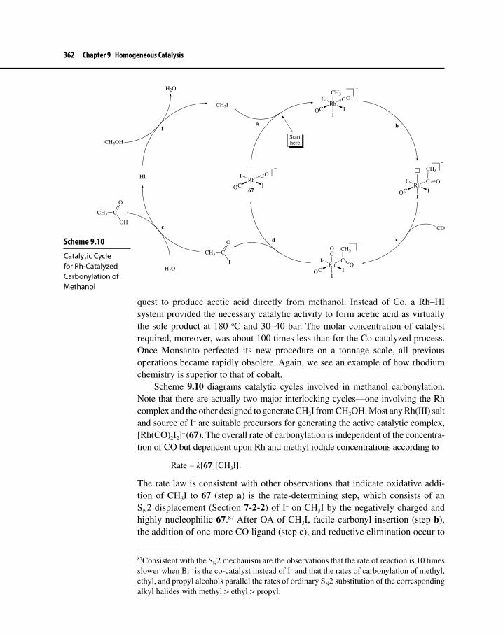
362 Chapter 9 Homogeneous Catalysis
quest to produce acetic acid directly from methanol. Instead of Co, a Rh–HI system provided the necessary catalytic activity to form acetic acid as virtually the sole product at 180 oC and 30–40 bar. The molar concentration of catalyst required, moreover, was about 100 times less than for the Co-catalyzed process. Once Monsanto perfected its new procedure on a tonnage scale, all previous operations became rapidly obsolete. Again, we see an example of how rhodium chemistry is superior to that of cobalt.
Scheme 9.10 diagrams catalytic cycles involved in methanol carbonylation. Note that there are actually two major interlocking cycles—one involving the Rh complex and the other designed to generate CH3I from CH3OH. Most any Rh(III) salt and source of I– are suitable precursors for generating the active catalytic complex, [Rh(CO)2I2]– (67). The overall rate of carbonylation is independent of the concentra-tion of CO but dependent upon Rh and methyl iodide concentrations according to
Rate = k[67][CH3I].
The rate law is consistent with other observations that indicate oxidative addi-tion of CH3I to 67 (step a) is the rate-determining step, which consists of an SN2 displacement (Section 7-2-2) of I– on CH3I by the negatively charged and highly nucleophilic 67.87 After OA of CH3I, facile carbonyl insertion (step b), the addition of one more CO ligand (step c), and reductive elimination occur to
87Consistent with the SN2 mechanism are the observations that the rate of reaction is 10 times slower when Br– is the co-catalyst instead of I– and that the rates of carbonylation of methyl, ethyl, and propyl alcohols parallel the rates of ordinary SN2 substitution of the corresponding alkyl halides with methyl > ethyl > propyl.
Scheme 9.10 Catalytic Cycle for Rh-Catalyzed Carbonylation of Methanol
RhC
I C
I
CH3
I
O
O
RhC
I C
I
C
IO
RhC
I C
II
CH3
O
ORhC
I C
I
O
O 67
CH3I
CH3 C
I
O
HI
CH3OH
H2O
CH3 C
OH
O
H2O
CO
a b
cd
e
f
Starthere
CH3O
O

9-5 Carbonylation of Methanol 363
regenerate 67 and produce acetyl iodide (step d), which subsequently undergoes rapid hydrolysis to acetic acid (step e). The by-product of the last step, HI, then reacts with additional CH3OH to yield CH3I (step f), allowing a new carbonyla-tion cycle to occur.88
Because acetic anhydride is more useful to the chemical industry than ace-tic acid, there was economic incentive to develop a process that would yield the anhydride directly without first producing the acid as a separate operation. By the early 1980s, Eastman Chemicals, in conjunction with Halcon Chemical Company, developed a procedure that provided acetic anhydride using technology similar to the Monsanto process, and since 1991 a plant run by Eastman has produced anhy-dride in excess of 500,000 metric tons per year.89 The Eastman–Halcon (E–H) operation amounts formally to inserting CO into the C−O bond of methyl acetate according to equation 9.36.90
CH3 O
O
C
CH3 C O
O
C
O
CH3 C CH3
O
9.36
88For a good discussion of the mechanism of Rh-catalyzed carbonylation, see articles written by chemists who were instrumental in developing the process at Monsanto: D. Forster, Adv. Organometal. Chem., 1979, 17, 255 and D. Forster and T. W. Dekleva, J. Chem. Ed., 1986, 63, 204, and references therein.89R. G. Smith, “Chemicals from Coal Operations,” Gasification Department, Eastman Chemical Company. A report presented at the 2000 Gasification Technologies Conference, San Francisco, Oct. 8–11, 2000.90S. W. Polichnowski, J. Chem. Ed., 1986, 63, 206 and J. R. Zoeller, J. D. Cloyd, J. L. Lafferty, V. A. Nicely, S. W. Polichnowski, and S. L. Cook, “Rhodium-Catalyzed Carbonylation of Methyl Acetate,” in Homogeneous Transition Metal Catalysis, W.R. Moses and D.W. Slocum, Eds., American Chemical Society: Washington, D.C., 1992, pp. 395–418.
The rate of carbonylation of 2-propanol to give a mixture of butanoic and 2-methylpropanoic acids is actually a little faster than that for carbonylation of ethanol and up to seven times more rapid than that for 1-propanol. If OA is still the rate-determining step in the pathway, what can be said about the mechanism of that step when 2-propanol is the starting material? [Hint: See Section 7-2-3]
Exercise 9-10
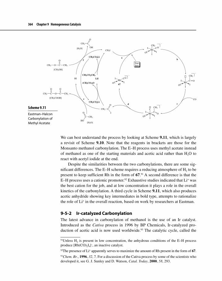
364 Chapter 9 Homogeneous Catalysis
We can best understand the process by looking at Scheme 9.11, which is largely a revisit of Scheme 9.10. Note that the reagents in brackets are those for the Monsanto methanol carbonylation. The E–H process uses methyl acetate instead of methanol as one of the starting materials and acetic acid rather than H2O to react with acetyl iodide at the end.
Despite the similarities between the two carbonylations, there are some sig-nificant differences. The E–H scheme requires a reducing atmosphere of H2 to be present to keep sufficient Rh in the form of 67.91 A second difference is that the E–H process uses a cationic promoter.92 Exhaustive studies indicated that Li+ was the best cation for the job, and at low concentration it plays a role in the overall kinetics of the carbonylation. A third cycle in Scheme 9.11, which also produces acetic anhydride showing key intermediates in bold type, attempts to rationalize the role of Li+ in the overall reaction, based on work by researchers at Eastman.
9-5-2 Ir-catalyzed CarbonylationThe latest advance in carbonylation of methanol is the use of an Ir catalyst. Introduced as the Cativa process in 1996 by BP Chemicals, Ir-catalyzed pro-duction of acetic acid is now used worldwide.93 The catalytic cycle, called the
91Unless H2 is present in low concentration, the anhydrous conditions of the E–H process produce [Rh(CO)2I4]–, an inactive catalyst.92The presence of Li+ apparently serves to maximize the amount of Rh present in the form of 67.93Chem. Br., 1996, 32, 7. For a discussion of the Cativa process by some of the scientists who developed it, see G. J. Sunley and D. Watson, Catal. Today, 2000, 58, 293.
Scheme 9.11 Eastman–Halcon Carbonylation of Methyl Acetate
RhC
I C
I
CH3
I
O
O
RhC
I C
I
O
O 67
CH3I
CH3 C
I
O
HI
[CH3OH]
CH3 C
OH
O
[H2O]
CO
ab
cd
e
fStarthere
CH3 C O
O
C CH3
O
CH3C
HO
O
CH3 O C
O
CH3
[H2O]
LiI
CH3CO2CH3
CH3CO2Li
CH3CO2Li
(CH3CO)2O
[CH3COOH]
RhC
I C
I
C
IO
CH3O
O
RhC
I C
II
CH3
O
O

9-5 Carbonylation of Methanol 365
anionic cycle and shown in Scheme 9.12, is quite similar to that for Rh-catalyzed carbonylation. Orginal work by Forster and others94 on the mechanism of Ir-catalyzed carbonylation demonstrated that there is actually an alternative path-way called the neutral cycle in which CH3I undergoes OA with neutral Ir(CO)3I or Ir(CO)2I instead of anionic [Ir(CO)2I2]–, analogous to the Rh-catalyzed reaction. Chemists consider the anionic cycle to be principally operative under industrial-scale conditions.95
Although the rate-determining step for Rh-catalyzed carbonylation is the OA of CH3I to [Rh(CO)2I2]–, the comparable step for the Cativa process (step a) is several hundred times faster. Migratory CO insertion, on the other hand, is very sluggish for [MeIr(CO)2I3]–, but studies have indicated that it is much faster if the
94D. Forster, J. Chem. Soc., Dalton Trans, 1979, 1639 and A. Haynes, et al., J. Am. Chem. Soc., 2004, 126, 2847.95M. Volpe, G. Wu, A. Iretskii, and P. C. Ford, Inorg. Chem., 2006, 45, 1861 and references therein.
Scheme 9.12The Anionic Cycle for Ir-Catalyzed Carbonylation of Methanol
IrI
I C
C
CH3
I
O
IrI
I C
C
I
C
CH3
O
IrI
I C
C
O
67
CO
a b
c
d
Starthere
O
CH3OH
HIH2O
CH3I
O
IrI
I CC
CH3
O
O
I−
IrI
I C
C
CH3
C
O
O
O
O
O
e
CH3COI CH3COOH
I−

366 Chapter 9 Homogeneous Catalysis
neutral intermediate MeIr(CO)3I2 forms first. This requires loss of I–, which is a slow step (step b). It is this loss of I– that is a bottleneck in the whole catalytic cycle, and until chemists discovered a way to unplug the bottleneck, Ir-catalyzed carbonylation was not feasible on an industrial scale.
A real breakthrough came with the discovery of promoter molecules that could be added to the reaction mixture. One such promoter is Ru(CO)3I2. Its mode of action seems to be in part to act as an I– abstractor from [MeIr(CO)2I3]– (equation 9.37), which has the effect of accelerating steps c and d. Several other transition metal carbonyl-iodo complexes will work, as will simple iodides of Zn, Cd, and Hg. Studies have shown that the iodinated promoter product is recycled by contributing its extra I– to the process for producing CH3I.
IrI
I C
C
CH3
I
O
OIr
II C
C
CH3
O
O
RuI
I C
CC
O
O
O
RuI
I C
C
I
C
O
O
O
9.37
The Cativa process offers several advantages over conventional Rh-catalyzed carbonylation, including the following:
• Employs an inherently more stable catalyst system (Ir−ligand bonds are usually stronger)
• Uses lower concentrations of H2O, thus minimizing the water gas shift reaction (see equation 9.1), and allows for easier separation of product
• The catalyst can exist over a wider range of conditions than comparable Rh catalysts before precipitating as IrI3
The Monsanto, E–H, and Cativa processes represent triumphs in the appli-cation of organotransition metal chemistry to catalysis, using homogeneous tran-sition metal compounds to promote production of valuable materials cheaply, efficiently, and selectively. Without question, fundamental work accomplished previously on the understanding of basic organometallic reaction types helped

9-6 Hydrocyanation 367
tremendously in the efforts required to unravel the intricacies of these and other cycles we have already considered. These catalytic processes and those consid-ered later in Chapter 9 and in following chapters provide beautiful illustrations of not only the basic reaction types in action, but also how scientific investigations can lead to practical applications of major economic significance.
9-6 HYDROCYANATIONHydrocyanation is the addition of HCN across a C=C bond. In 1971, Dupont reported a new process that added two equivalents of HCN, in an anti- Markovnikov manner, to 1,3-butadiene to yield adiponitrile (equation 9.38).96 The process is catalyzed overall by a Ni(0) triarylphosphite complex.
+ 2 H−CNNi[P(OAr)3]4
NCCN
H
H
9.38
Adiponitrile is an extremely important compound because it may be hydroge-nated over a heterogeneous catalyst to give 1,6-hexanediamine or hydrolyzed to yield adipic acid. Both products are used in the production of the polyamide nylon 66, one of the most common nylon polymers used today (Scheme 9.13).97
The mechanism of hydrocyanation turns out to be another classic example of a set of catalytic cycles that use many of the fundamental types of organometallic reactions that we have already encountered. In fact, the investigation of the details of this mechanism went hand in hand with the advancement of important general
96Chem. Eng. News, 1971, 49, 30.97Adipic acid is also made on an industrial scale through oxidation of cyclohexanone. The number 66 represents the number of carbons in the two different monomeric units of nylon 66; both adipic acid and 1,6-hexanediamine contain six carbon atoms. Nylon 6 is made from only one type of monomeric unit, which also contains six carbon atoms.
CC
N
N
H2
Ni(0) or Pd/C
1) NaOH/H2O
2) H+/H2O
H2NNH2
HO2CCO2H
(CH2)4
O O
HN (CH2)4 H
N
Nylon 66
Scheme 9.13 Conversion of Adiponitrile to Nylon 66

368 Chapter 9 Homogeneous Catalysis
concepts about basic organometallic reactions and catalytic cycles that we accept as valid today.98
Hydrocyanation of 1,3-butadiene occurs in three stages. Equation 9.39 shows the first stage, which produces a 2:1 mixture of the desired 3-pentenenitrile (68), produced by a 1,4-addition of HCN to 1,3-butadiene, and the branched isomer 2-methyl-3-butenenitrile (69), which results from Markovinikov 1,2-addition.
HCN
Ni(0) catalyst CN+
CN68 69
2 : 1
9.39
The next stage requires equilibration and isomerization of 69 to 68, giving a 9:1 ratio of desired to undesired product. A Ni catalyst is also used for this reaction. Finally, the third stage consists of two transformations, where 68 is first isomer-ized to 4-pentenenitrile (70) under kinetic control, fortunately without producing much of the thermodynamically more stable 2-pentenenitrile (71). Compound 70 then undergoes a second hydrocyanation with anti-Markovnikov orientation (equation 9.40). In this last Ni-catalyzed stage of the overall process, a Lewis acid, such as Ph3B, is added to ensure that linear rather than branched product (72) forms.
CN
68
CN
70
Ni(0)cat.
CN
71(not favored kinetically)
Ni(0) cat./BPh3CN
NC
+
CN
CN
(mostly)
72
HCN
9.40
98For an excellent overview, written by a Dupont chemist, of the development of the adiponitrile process and the investigation of its fundamental chemistry, see C. A. Tolman, J. Chem. Ed., 1986, 63, 199; for a key research paper on Tolman’s work, see C. A. Tolman, W. C. Seidel, J. D. Druliner, and P. J. Domaille, Organometallics, 1984, 3, 33.
Exercise 9-11 Why is formation of 68 favored over formation of 69? Why is 68 or 70 less stable than 71?

9-6 Hydrocyanation 369
Although details of the catalytic cycle that converts 1,3-butadiene to 68 remain proprietary information, a thorough study has been reported on the catalytic cycle for hydrocyanation of ethene to give propanenitrile.99 The buta-diene cycle must be quite similar in most aspects. Scheme 9.14 shows the major steps in propanenitrile formation. The L ligand is typically a phosphite, such as P(O-o-tolyl)3, which possesses a large cone angle (θ = 141o). Such a large value of θ seems to promote the dissociation of L in the precatalyst NiL4
99R. J. McKinney and D. C. Roe, J. Am. Chem. Soc., 1986, 108, 5167.
Scheme 9.14 Catalytic Cycle for Hydrocyanation of Ethene
L2Ni
NiL
LH
C
N
HCN
L
NiH
C LN
NiL
L
CH2CH2
C
N
NiCH3CH2
C LN
CN
a
b
c
d
e
L
Starthere
L = P(O-o-tolyl)3
370 Chapter 9 Homogeneous Catalysis
and also assists RE in the last step (step e). Phosphites also possess relatively high χ values, which helps to stabilize the electron-rich Ni(0) complex that forms after RE.
Step a involves OA of HCN to give an 18-electron complex. Steps b and c involve loss of phosphite ligand, followed by migratory 1,2-insertion of ethene into a Ni−H bond, which is driven by the presence of excess ethene. Step e requires a RE to give product and regenerate the active Ni(0) catalyst species. Investigation showed that step e must have been preceded by complexation of L (step d) to give an 18-electron intermediate. This amounts to RE by a relatively rare associative mechanism (see Section 7-3). Researchers pointed out that the addition of one more equivalent of phosphite both increased steric hindrance, which is relieved by RE, and provided another electron-withdrawing ligand that stabilized the electron-rich Ni(0) complex resulting from RE.
Scheme 9.15 shows the cycles that are assumed to represent conversion of 1,3-butadiene to either 68 or 69, which are quite similar to that for ethene hydro-cyanation.100 Intermediates in these cycles, however, consist of η2–butadiene complexes or η3–allyl complexes that form after insertion of one of the C=C bonds of the diene into the Ni−H bond.
The isomerization of 69 to 68 is of interest to chemists. A French group has studied the isomerization using a Ni(II) complex 73, which they generated in situ from a combination of Ni(COD)2, 69, and bis(diphenylphosphino)butane (dppb).101 Isomerization of 69 to 68 in the presence of a catalytic amount of 73 occurred with 97% conversion and 83% selectivity for the formation of 68. DFT-B3LYP MO calculations performed by the same group supported a catalytic cycle shown in Scheme 9.16. Here PH3 was substituted for dppb to make high-level calculations accessible. Steps b and e represent C−CN bond breaking (a relatively rare C−C bond activation, see Section 7-2-1) and formation (RE), respectively. Other experimental work has supported the feasibility of step b.102 Although the chemistry shown in Scheme 9.16 may not represent exactly the mechanism that occurs under the real-world circumstances of the Dupont process, it represents a reasonable scenario for a Ni(0)-catalyzed isomerization that could occur under mild conditions.
100See Footnote 99.101A. Chaumonnot, F. Lamy, S. Sabo-Etienne, B. Donnadieu, B. Chaudret, J.-C. Barthalat, and J.-C. Galland, Organometallics, 2004, 23, 3363.102N. M. Brunkan, D. M. Brestensky, and W. D. Jones, J. Am. Chem. Soc., 2004, 126, 3627.

9-6 Hydrocyanation 371
Scheme 9.15 Catalytic Cycles for Hydrocyanation of 1,3-Butadiene
NiL4
L
NiL3
HCN
HNiL
LL
C
N
NiH
CL
L
N L
NiL
LH
C
N
NiCL
L
N
NiL
L
NC
NiL
CN
CN
CN
LL
L
L
L
L = P(OAr)3
Starthere
68
69
NiCN
PPh2
Ph2P
73
Studies have shown that bidentate phosphine and phosphite ligands have improved selection for 68 over 69.103 Such ligands, with βn values of around 109o,
103P. W. N. M. van Leeuwen, Homogeneous Catalysis: Understanding the Art, Kluwer Academic: Dordrecht, The Netherlands, 2004, pp. 233–236, and references therein.

372 Chapter 9 Homogeneous Catalysis
seem to destabilize square planar Ni(II) complexes that might form according to equation 9.41. The resulting dicyano–Ni complexes that form here after a second OA of HCN are incapable of being regenerated to a catalytically active species, so it is vital that such reactions be suppressed. A Ni(0) complex of COD and bidentate ligand 74 proved to be particularly successful in catalyzing the conver-sion of 1,3-butadiene to a 97.5/2.5 ratio of 68 to 69.104
104L. Bini, C. Müller, J. Wilting, L. von Chrzanowski, A. L. Spek, and D. Vogt, J. Am. Chem. Soc., 2007, 129, 12622.
Scheme 9.16 Catalytic Cycle for Isomerization of 69 to 68
Ni(COD)2
2 COD
2 PH3
Ni(PH3)2
CN
Ni
PH3H3P
CN
CNNi
H3P PH3
NiH3P
H3P
CN
NiCN
PH3
H3P
NiPH3
PH3
NC
NCNi
PH3H3P
Ni
PH3H3P
NC
NC
a
b
cd
e
f
Starthere
68 69

9-6 Hydrocyanation 373
NiH
CNL
LNi
CN
CNL
L
HCN H2
or
NiCH2CH3
CNL
L
HCN CH3CH3
NiCN
CNL
L
L
LO
PPh2
PPh2
:
9.41
Ph2PPh2P
74
The last steps in hydrocyanation of 1,3-butadiene involve first isomerization to 70 and then anti-Markovnikov addition of HCN to the remaining C=C bond,
Why does the incorporation of a rigid, diphospine ligand with βn of about 110o cause destabilization of square planar Ni(II) complexes?
Exercise 9-12

374 Chapter 9 Homogeneous Catalysis
according to a catalytic cycle presumably similar to that shown in Scheme 9.14. The role of a Lewis acid promoter such as BPh3 in these end steps is not completely clear. BPh3 may bind to the nitrogen end of a CN ligand (Scheme 9.17), causing dissocia-tion of the CN–BPh3 ligand from the Ni to give a cationic nickel hydride complex 75 that can bind 68 to yield complex 76. 1,2-Insertion and β-elimination complete the cycle to give 70. The presence of the sterically bulky CN–BPh3 ligand also favors formation of the less sterically hindered complex 78 over more sterically congested 77, thus allowing adiponitrile to form in the last step as a result of RE.105
105G. W. Parshall and S. D. Ittel, Homogeneous Catalysis, 2nd ed., Wiley–Interscience: New York, 1992, pp. 42–47.
Scheme 9.17 The Final Steps in Hydrocyanation of 1,3-Butadiene
HNiL3(CN-A)
HNiL3+ −CN-A
NiLL
H
L
CN
−CN-A
NiL
L
CN-A
CN
NiLL
H
CN-A
CN
CN
NiL
L
CN-A
CN
L
A = BPh3L = P(OAr)3
NiL4
HCN/A
L
Starthere
CN68
75
76
7778
NC
70
HCN/A

9-7 Specialty Chemicals 375
9-7 SPECIALTY CHEMICALSAs the science of organometallic chemistry has developed over the past decades, it has become apparent that transition metal complexes can serve as extremely efficient and highly selective catalysts. These catalysts can control not only the chemoselectivity of the reaction but also its regio- and, more important, stereoselectivity.
The demand for new compounds that can alleviate human ailments and safely control agricultural pests continues to increase. Many of these compounds are chiral, sometimes possessing several stereogenic centers. Usually only one enantiomer or diastereomer is active. Racemic modifications are often unaccept-able because 50% of the drug or pesticide is at best useless and sometimes even toxic to the patient or the environment. The chemical industry and especially manufacturers of pharmaceuticals and agricultural chemicals have focused their efforts recently on developing homogeneous catalysts that can control the selec-tivity of key steps in the synthesis of these specialty compounds.106 Although the expense of catalyst material and the cost of developmental research are both high in designing these selective catalysts, the payoff resulting from successful efforts can be enormous.
In these endeavors, therefore, selectivity becomes ever more important because unselective reactions generate waste products that sometimes cost more to dispose of than the original cost of the starting materials.107 Moreover, these waste materials are often quite toxic. The atom economy principle of green chemistry dictates that the sustainable approach is to design chemical processes so that all or almost all of the atoms put into a chemical reaction end up in the desired product. The use of homogenous transition metal catalysts can be of tremendous benefit in maximizing atom economy, enhancing all three types of selectivity, and minimizing waste production. The rest of this section will briefly explore three examples where homogeneous catalysis played a major role in the successful synthesis of biologically important molecules of commercial significance.
106Specialty chemicals are also called fine chemicals. Fine chemicals possess relatively complex structures, sometimes with several stereogenic centers; are produced on a smaller scale than bulk petrochemicals, such as acetic acid (<10,000 tons/year); and their synthesis often involves several chemical steps. For a good summary on the role of Pd catalysts in the synthesis of fine chemicals, see A. Zapf and M. Beller, Top. Catal., 2002, 19, 101. 107There is an inverse relationship between the scale of chemical production and the percent-age of waste products generated. Synthesis of petrochemicals on a scale of billions of pounds generates a very small amount of waste compared with the volume of starting material. On the other hand, for every pound of a drug produced there could be hundreds of pounds of waste generated (resulting in a very unfavorable E-factor, which is the ratio of the total mass of waste to the total mass of desired product).
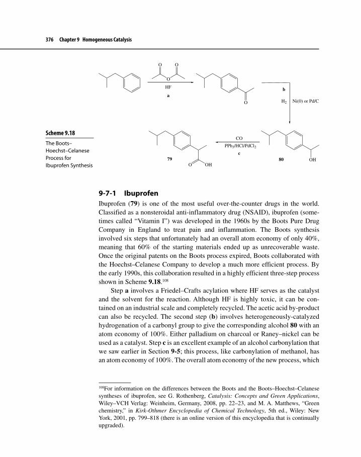
376 Chapter 9 Homogeneous Catalysis
9-7-1 IbuprofenIbuprofen (79) is one of the most useful over-the-counter drugs in the world. Classified as a nonsteroidal anti-inflammatory drug (NSAID), ibuprofen (some-times called “Vitamin I”) was developed in the 1960s by the Boots Pure Drug Company in England to treat pain and inflammation. The Boots synthesis involved six steps that unfortunately had an overall atom economy of only 40%, meaning that 60% of the starting materials ended up as unrecoverable waste. Once the original patents on the Boots process expired, Boots collaborated with the Hoechst–Celanese Company to develop a much more efficient process. By the early 1990s, this collaboration resulted in a highly efficient three-step process shown in Scheme 9.18.108
Step a involves a Friedel–Crafts acylation where HF serves as the catalyst and the solvent for the reaction. Although HF is highly toxic, it can be con-tained on an industrial scale and completely recycled. The acetic acid by-product can also be recycled. The second step (b) involves heterogeneously-catalyzed hydrogenation of a carbonyl group to give the corresponding alcohol 80 with an atom economy of 100%. Either palladium on charcoal or Raney–nickel can be used as a catalyst. Step c is an excellent example of an alcohol carbonylation that we saw earlier in Section 9-5; this process, like carbonylation of methanol, has an atom economy of 100%. The overall atom economy of the new process, which
108For information on the differences between the Boots and the Boots–Hoechst–Celanese syntheses of ibuprofen, see G. Rothenberg, Catalysis: Concepts and Green Applications, Wiley–VCH Verlag: Weinheim, Germany, 2008, pp. 22–23, and M. A. Matthews, “Green chemistry,” in Kirk-Othmer Encyclopedia of Chemical Technology, 5th ed., Wiley: New York, 2001, pp. 799–818 (there is an online version of this encyclopedia that is continually upgraded).
Scheme 9.18 The Boots–Hoechst–Celanese Process for Ibuprofen Synthesis
O
O O
HF
O Ni(0) or Pd/CH2
OH
CO
PPh3/HCl/PdCl2
OHO79
ab
c80

9-7 Specialty Chemicals 377
produces about 3500 tons/year of ibuprofen, is 77%; however, if the recycling of acetic acid is taken into account, the atom economy is close to 100%.109
The homogenously-catalyzed process involved with step c will be the focus of the following discussion. Note here that a Pd catalyst was used instead of one containing Rh or Ir, but the steps of the catalytic process are very similar to those for methanol carbonylation. Scheme 9.19 outlines the catalytic cycle.
109In 1997, the developers of the Boots–Hoechst–Celanese process were awarded the Presidential Green Chemistry Award, sponsored by the U.S. Environmental Protection Agency.
PdCl2(PPh3)2
CO
2 Cl−
Pd(CO)(PPh3)2
PdC
Ph3P Cl
O
Pd
C
Ph3P PPh3
ClO
PPh3
Cl
O
Ibuprofen
HCl
H2O
HO
H2O
Cl
PPh3
CO
81
a
b
c
d
e
82
80
Scheme 9.19 Catalytic Cycle for the Carbonylation Step of the Boots–Hoechst–Celanese Synthesis of Ibuprofen

378 Chapter 9 Homogeneous Catalysis
The precatalyst is PdCl2(PPh3)2, which is converted to Pd(CO)(PPh3)2 under the reducing conditions of the reaction. Once the catalyst is generated, benzyl chloride 81, generated from a secondary cycle involving steps d and e, enters the cycle and undergoes OA (step a). Migratory CO insertion (step b) precedes RE (step c), which regenerates the catalyst and produces acid chloride 82. Hydrolysis of 82 (step d) yields ibuprofen and HCl, which then reacts with alcohol 80 to produce 81.110
Ibuprofen possesses a stereogenic center, and studies have shown that (S)-ibuprofen is the active enantiomer. A chiral synthesis of (S)-ibuprofen, which is suitable for an industrial scale, has been developed by the Cheminor Company in India.111 Subsequent biochemical studies of racemic ibuprofen in mammalian tissue, however, have shown that there is an isomerase enzyme available in the body that can convert the R-enantiomer to (S)-ibuprofen.112 Since this discovery, enthusiasm for the production of chiral ibuprofen has waned. Racemic ibuprofen is the only form of the drug that is currently readily available.
9-7-2 (S)-Metolachlor(S)-Metolachlor is the active ingredient of the herbicides Dual and Bicep, which are widely applied in the United States and were developed by the Swiss company Ciba–Geigy (now Novartis). The steric hindrance near the aryl−N bond restricts rotation about that bond. This restricted rotation results in a type of stereoisomer-ism called atropisomerism, resulting in aR and aS configurations about the chiral aryl−N bond axis.113 There is also a stereogenic center (position 1) on a carbon next to the N-atom in the amino side chain. All four possible stereoisomers of metolachlor are shown in Figure 9-3.
It turns out that only the isomers with the S-configuration at position 1 are active herbicides, regardless of the configuration of the chiral axis (aR or aS).
Scheme 9.20 illustrates the last key steps in the synthesis of (S)-metolachlor. Early on, researchers at Novartis turned their attention to creating conditions for an asymmetric, homogeneous, metal-catalyzed hydrogenation of imine 83 to
110For more details on the catalytic cycle, see R. A. Sheldon, I. Arends, and U. Henefeld, Green Chemistry and Catalysis, Wiley–VCH Verlag: Weinheim, Germany, 2007, pp. 247–249 and E. J. Jang, K. H. Lee, and Y. G. Kim, J. Mol. Catal. A, 1999, 138, 25.111A. S. Bommarius and B. R. Riebel-Bommarius, Biocatalysis: Fundamentals and Applications, Wiley–VCH Verlag: Weinheim, Germany, 2004, p. 578.112C. Reichel, R. Brugger, H. Bang, G. Geisslinger, and K. Brune, Mol. Pharmacol., 1997, 51, 576.113The descriptor “a” stands for axis or axial. Molecules that exhibit atropisomerism are chi-ral because of the presence of a chiral axis rather than a chirality center. For a discussion of chiral axes and atropisomerism, see E. L. Eliel and S. H. Wilen, Stereochemistry of Organic Compounds, Wiley–Interscience: New York, 1994, Chap. 14.

9-7 Specialty Chemicals 379
amine 84. It took considerable effort over almost a 20-year period for Novartis chemists to determine that a cationic Ir catalyst would be most suitable. For chi-rality to be induced during the hydrogenation, a chiral environment must exist during the addition of H2 to the C=N bond. Chiral bisphosphine ligands, such as DIPAMP used in the synthesis of L-Dopa, must be attached to the metal catalyst to provide that environment. A search of possible ligands eventually zeroed in on bisphosphine 85, a so-called Josiphos ligand that is a ligand based on ferrocene and is also known as xyliphos.114 Equation 9.42 details the final reaction conditions developed for asymmetric hydrogenation of 83.
Regardless of the ultimate success of (S)-metolachlor as a herbicide, the development of the key asymmetric hydrogenation step was a significant tri-umph in transition metal homogeneous catalysis on an industrial scale. The pro-cess is considered the largest application of asymmetric catalysis in terms of amount of product produced (a production capacity of 10,000 tons/year). The process is characterized by an extremely high TOF (>1.8 × 10⁶/hour) and a very favorable substrate/catalyst ratio of 106 to 1. Even though the ee of the process is only about 80%, this is acceptable for the final application in the field; higher
114For an article on the discovery and development of Josiphos ligands, eponymously derived from the first name of the chemist who first synthesized them, see H.-U. Blaser, W. Brieden, B. Pugin, F. Spindler, M. Studer, and A. Togni, Top. Catal., 2002, 19, 3.
Figure 9-3 Stereoisomers of Metolachlor
aR,S
N CH2Cl
OMeO
N CH2Cl
OMeO
Me
H N CH2Cl
OMeO
aR,R
N CH2Cl
OMeO
Me
H
Me
H
1 1 1 1
aS,S aS,R
Active isomers
Me
H
Scheme 9.20 Final Steps in the Synthesis of (S)-Metolachlor
NMe
MeO
H2
Ir-Xyliphos (cat.)HOAc/I−
NHMe
MeO
HClCH2COCl
NMe
MeO
H CH2Cl
O
83 84 (S)-Metolachlor

380 Chapter 9 Homogeneous Catalysis
values of ee can be achieved, but with less favorable TOF and substrate/catalyst ratios.115
9-7-3 (–)-Menthol(−)-Menthol (88) is an important fragrance ingredient that finds use as a food additive and in cold remedies. Although it is obtainable from natural sources, workers at the Takasago Perfumery in Japan developed a route to 88 outlined in Scheme 9.21.116 Run on a 3000–4000 ton/year scale, the process now accounts for about one third of the world’s supply of (−)-menthol. The key step in the synthesis is the stereoselective isomerization of (E)-vinylamine 86 to enamine 87. This step induces chirality at the 3-position and is catalyzed by [Rh(S)-(−)-BINAP(COD)]ClO4, where (S)-(−)-BINAP (89) is a now well-known chiral bis-phosphine ligand. The enantiomeric (R)-(+) ligand is also shown as structure 90 in Scheme 9.21.
Double bond migration such as that involved in 86 going to 87 is an impor-tant reaction, useful on both an industrial and a laboratory scale; its mechanism has been well studied. Equations 9.43 and 9.44 describe two major pathways for migration, the former involving metal hydride insertion and β-elimination steps
115For a rendition of the story behind the research and development of the asymmetric hydrogenation in the synthesis of (S)-metolachlor, see H.-U. Blaser, Adv. Synth. Catal., 2002, 344, 17.116S. Inoue, H. Takaya, K. Tani, S. Otsuka, T. Sato, and R. Noyori, J. Am. Chem. Soc., 1990, 112, 4897 and R. Noyori and H. Takaya, Acc. Chem. Res., 1990, 23, 345.
83 84[Ir-85]+/HOAc/I−/50 oC/4 h
H2 (80 bar)
Fe
PPh2
P
MeMe
Me
Me
Me
H
85: Xyliphos (Josiphos)
9.42

9-7 Specialty Chemicals 381
and the latter a 1,3-hydride shift via a η3 π–allyl intermediate. The researchers at Takasago proposed a third mechanism for bond migration, outlined in equation 9.45, which they termed “nitrogen triggered.”
H−M
H H
M M−H
9.43
HM M H H M
9.44
NR2
M+
H
NR2
MH
NR2
H M
9.45
Scheme 9.21 Chiral Synthesis of (−)-Menthol
Et2NH
Li
Me
NEt2 Rh[(S)-(−)-BINAP]*
THF
Me
NEt2
H2O
Me
H
O
ZnBr2
∆
Me
OH
H2
Me
OH
88
8786
(−)-Menthol *Actual catalyst: Rh[(S)-(−)-BINAP][THF]2+ ClO4
−
Ni(0)
PPh2
PPh2
(R)-(+)-BINAP
PPh2
PPh2
(S)-(−)-BINAP
89 90

382 Chapter 9 Homogeneous Catalysis
Scheme 9.22 describes the nitrogen-triggered pathway. Steps a and b provide an activated Rh–BINAP complex (91) by associative substitution of solvent (EtOH or THF) and substrate followed by β-elimination to form an iminium complex. The stereochemically key step, c, adds a proton to the 3-position and gives the complexed enamine. In step d, the η3 enamine ligand shifts to η1 as a new molecule of allyl amine adds to the complex. The nitrogen plays a key role in activating the Rh, particularly in step d, the rate-determining step of the overall cycle. Step e liberates enamine product and regenerates 91.117
117A later paper by workers associated with the Takasago process reported on ab initio MO calculations for the catalytic cycle. Their work suggested that steps b and c (Scheme 9.22) involved an intramolecular OA of C−H, followed by a RE in which the hydride ligand attached itself to the terminal carbon of the allyl group. See M. Yamakawa and R. Noyori, Organometallics, 1992, 11, 3167. It is not clear which pathway is correct because the theoretical study used only PH3 and not BINAP to model the Rh-catalyzed isomerization. See also C. Chapuis, M. Barthe, and J.-Y. de Saint Laumer, Helv. Chim. Acta, 2001, 84, 230.
Scheme 9.22 Rh–BINAP-Catalyzed Double Bond Isomerization
RhP
P Solv
Solv
NR2
Solv
RhP
P NR2
Solv
1
2Solv
3
RhP
P
H
NR2
RhP
PNR2
H
RhP
P
R2N
NR2
3
21
3
2
1
RhP
P
R2N
NR2
91
a
b
c
d
eNR2
NR2

9-7 Specialty Chemicals 383
Predict the product of the following transformation. Indicate the expected stereochemistry of the product.
NEt2
Me
Rh[(+)-BINAP]+
Exercise 9-13
The isomerization of the double bond in the synthesis of (−)-menthol is stereospecific. Evidence obtained using vinyl amine specifically deuterated at C-1 indicates that the transfer of a proton from C-1 to C-3 is suprafacial,118 as indicated by equation 9.46. Equation 9.47 illustrates how the chirality of the BINAP ligand and the stereochemistry of the trisubstituted double bond in 86 control the stereo-chemistry of the methyl group at C-3 in 87 upon double bond migration.
NEt2
Me Me D H
12
3 Rh[(S)-(−)-BINAP]+ NEt2
Me Me
12
3
H D
9.46
R
NEt2
Me
Rh[(S)-(−)-BINAP]+ R NEt2
Me
R NEt2
Me
Rh[(S)-(−)-BINAP]+
Rh[(R)-(+)-BINAP]+
R NEt2
Me
R =
Me
1
2
3
12
3
12
332
1
(Z)-86
(E)-86
(S)-87
(R)-87
9.47
118With regard to sigmatropic shifts such as a 1,3-hydride shift, the word “suprafacial” means that the migrating group moves along the same face of the π system from one end to the other. An “antarafacial” migration results in the movement of the group to the opposite face of the π system. See J.E. McMurry, Organic Chemistry, 7th ed., Thompson–Brooks/Cole: Belmont, CA, 2008, Chapter 30, especially pp. 1191–1195, and F. A. Carey and R. J. Sundberg, Advanced Organic Chemistry Part A, 5th ed., Springer Scientific: New York, 2007, Chap. 10, especially pp. 911–935, for a more detailed definition accompanied by other examples.

384 Chapter 9 Homogeneous Catalysis
A Biological Double Bond Migration
It is interesting to note that this Rh-catalyzed isomerization mimics a similar double bond migration found in nature in the biosynthesis of cholesterol and terpenes in which isopen-tenyl diphosphate (92) is converted reversibly to dimethylallyl diphosphate (93), shown in equation 9.48.119 The stereochemistry of this reaction is also suprafacial.
HZ
HE
CH3
OPPHS HR HS
CH3
HE
HZ
HR
OPP
92 93
OPP = diphosphate
Isomerase
9.48
The Rh-catalyzed isomerization step of the Takasago synthesis of (−)- menthol is highly efficient. With modification of the catalyst precursor (still based on BINAP and its derivatives), the % ee has risen to 99% with a TON of up to 400,000 (if catalyst recycling occurs). The isomerization step is also useful in producing precursors to (+)-cis-p-menthane-3,8-diol (94), which shows promise as an insect repellant that could replace DEET, the most common repellant sold today.120
Me
OH
94
OH
119For a good discussion of the role of double bond isomerization in steroid and terpene biosynthesis, see C. D. Poulter and H. C. Rilling, “Prenyl Transferases and Isomerases,” In Biosynthesis of Isoprenoid Compounds, Vol. 1, J. W. Porter and S. L. Spurgeon, Eds., Wiley: New York, 1981, pp. 161–224.120For more information on the Takasago (−)-menthol synthesis, see H. Kumobayashi, Recl. Trav. Chim. Pays-Bas, 1996, 115, 201; C. Chapuis and D. Jacoby, Appl. Catal. A, 2001, 221, 93; and G. P. Chiusoli and P. M. Maitlis, Metal-Catalysis in Industrial Organic Processes, RSC Publishing: Cambridge, 2006, pp. 103–107.

Suggested Readings 385
The syntheses of ibuprofen, (S)-metolachlor, and (−)-menthol represent only three of the numerous uses of soluble transition metal complexes to catalyze, often stereoselectively, key steps in the production of biologically important com-pounds in the laboratory or on an industrial scale. Discussions in Chapter 12, especially with regard to asymmetric conditions, will explore more fully the use of these catalysts in the synthesis of other organic compounds.
Suggested Readings
General References on Homogeneous CatalysisG. Rothenberg, Catalysis: Concepts and Green Applications, Wiley–VCH: Weinheim,
Germany, 2008. An excellent resource for those interested in green chemistry.R. A. Sheldon, I. Arends, and U. Hanefeld, Green Chemistry and Catalysis, Wiley–
VCH: Weinheim, Germany, 2007.J. Hagen, Industrial Catalysis: A Practical Approach, 2nd ed., Wiley–VCH: Weinheim,
Germany, 2006.G. P. Chiusoli and P. M. Maitlis, Metal-Catalysis in Industrial Organic Processes, RSC
Publishing: Cambridge, 2006.P. W. N. M. van Leeuwen, Homogeneous Catalysis: Understanding the Art, Kluwer
Academic: Dordrecht, The Netherlands, 2004.Applied Homogeneous Catalysis with Organometallic Compounds: A Comprehensive
Handbook in Three Volumes, 2nd ed., B. Cornils and W. A. Herrmann, Eds., Wiley–VCH: Weinheim, Germany, 2002.
HydroformylationK.-D. Wiese and D. Obst, “Hydroformylation,” Top. Organometal. Chem., 2006, 18, 1.F. Ungváry, “Hydroformylation—Homogeneous,” in Encyclopedia of Catalysis,
I. T. Horváth, Ed., Wiley–Interscience: New York, 2003, Vol. 3, pp. 734–787.C. Kohlpaintner, “Hydroformylation—Industrial,” in Encyclopedia of Catalysis,
I. T. Horváth, Ed., Wiley–Interscience: New York, 2003, Vol. 3, pp. 787–808.Rhodium Catalyzed Hydroformylation, P. W. N. M. van Leeuven and C. Claver, Eds.,
Kluwer Academic: Boston, 2002.J. J. Carbó, F. Maseras, and C. Bo, “Rhodium Diphosphine Hydroformylation,” in
Computational Modeling of Homogeneous Catalysis, F. Maseras and A. Lledós, Eds., Kluwer Academic: Dordrecht, The Netherlands, 2002, pp. 161–187.
Wacker OxidationP. M. Henry, “Palladium-Catalyzed Reactions Involving Nucleophilic Attack on
π-Ligands of Palladium-Alkene, Palladium-Alkyne, and Related Derivatives,” in Handbook of Organopalladium Chemistry for Organic Synthesis, E.-i. Negishi, Ed., Wiley–Interscience: New York, 2002, pp. 2119–2139.

386 Chapter 9 Homogeneous Catalysis
HydrogenationJ. G. de Vries and C. J. Elsevier, Eds., Homogeneous Hydrogenation, Wiley–Interscience:
New York, 2007, Vol. 1–3.
Carbonylation of MethanolA. Haynes, “Acetic Acid Synthesis by Catalytic Carbonylation of Methanol,” Top.
Organomet. Chem., 2006, 18, 179.
HydrocyanationK. Huthmacher and S. Krill, “Reactions with Hydrogen Cyanide (Hydrocyanation),”
in Applied Homogeneous Catalysis with Organometallic Compounds, 2nd ed., B. Cornils and W.A. Herrmann, Eds., Wiley–VCH: Weinheim, Germany, 2002 Vol. 1, pp. 468–490.
Specialty ChemicalsE. J. Jang, K. H. Lee, J. S. Lee, and Y. G. Kim, J. Mol. Catal. A, 1999, 138, 25
[Ibuprofen].H.-U. Blaser, Adv. Synth. Catal., 2002, 344, 17 [(S)-Metolachlor].S. Otsuka, Acta Chim. Scand., 1996, 50, 353 [(−)-Menthol and related compounds].
Problems9-1 The complex Rh(H)(CO)2(PPh3)2 can be used in the catalytic synthe-
sis of pentanal from an alkene having one less carbon atom. Propose a mechanism for this synthesis. In your mechanism, indicate the reaction type of each step. Identify the catalytic species.
9-2 Increasing the concentration of CO during Co-catalyzed hydroformyla-tion not only retards the reaction rate, but also suppresses the tendency of the reaction to add a formyl group (CHO) to a carbon other than those contained in the C=C bond of the starting alkene (i.e., an isomer-ization of the double bond does not occur during the catalytic cycle). Explain.
9-3 Propose a catalytic cycle for hydrogenation step in the production of (S)-metolachlor using the cationic Ir complex described in Section 9-7-2.
9-4 Propose a mechanism for step e of Scheme 9.22. This transformation requires more than one step. Be sure to count electrons for each species in your pathway.
9-5 On the next page is the catalytic cycle associated with the Heck olefina-tion reaction. For each step marked with a letter, attach the name of one of the fundamental types of organometallic reactions (e.g., nucleophilic abstraction or ligand substitution).

Problems 387
Pd(II)
Pd(0)
R−Pd(II)−X
Y
Pd(II)R X
H
R
H
Pd(II)−X
Y
H−Pd(II)−X
H−XEt3N
Et3NH+ Cl− R−X
Y
Y
R
a
b
c
d
e
9-6 Consider the transformation of an alkyl bromide to an aldehyde shown below.
1-bromobutane pentanal + HBr
Assume that the reaction is catalyzed by HFe(CO)4– in an atmosphere
rich in CO and H2. Propose a catalytic cycle that would show this cataly-sis and account for the formation of the two products. Label each step in your cycle with terms corresponding to the fundamental organometallic reaction types.
9-7 The transformation below is reminiscent of Wacker chemistry described in Chapter 9.
H
O
Ph
O
+ CuCl2 + LiCl
O
H
Cl
Ph
Cl
O
Pd(II) (cat.)
A catalytic cycle has been proposed and is shown on the next page.121 One of the steps is an example of a relatively rare type of reaction discussed in
121S. Ma and X. Lu, J. Org. Chem., 1993, 58, 1245.

388 Chapter 9 Homogeneous Catalysis
Section 8-1-2. Describe in detail what is happening in each of the four major transformations in the cycle. What is the function of CuCl2?
H
O
Ph
O
H
O
Ph
O
Cl
Pd
Cl
L2PdCl2
O
PhCl
HPd
Cl
O
L
2 L
O
H
Cl
Ph
PdL2Cl
O
2 CuCl2
O
H
Cl
Ph
Cl
O
+ 2 CuCl
L
L
a
b
c
d
9–8 Catalytic, selective functionalization of hydrocarbons is one of the most important goals of organometallic chemistry. A report in the literature describes the Rh-catalyzed conversion of benzene to benzaldehyde under photochemical conditions.122
Rh(PMe3)2(CO)ClPh−H + CO Ph C
H
Ohν
Assuming that the first step in the catalytic cycle is photoactivation of the Rh complex, propose a possible mechanism for the transformation above.
9-9 The transformation on the next page is called hydroaminomethylation, first reported by Reppe over 60 years ago. There are four stages to this process,
122G. P. Rosini, W. T. Boese, and A. S. Goldman, J. Am. Chem. Soc., 1994, 116, 9498.

Problems 389
all of which occur in the same reaction vessel! Three of these are catalyzed by the same Rh catalyst. First, internal alkenes are isomerized to termi-nal alkenes. Next, the terminal alkene undergoes hydroformylation with a preference for formation of linear instead of branched aldehyde. Third, the aldehyde reacts with an amine (without catalysis) to give the imine, which undergoes Rh-catalyzed hydrogenation to the amine in the last step. Assuming that the active catalyst is of the form shown in structure 1, pro-pose mechanisms for the isomerization of internal to terminal alkenes and for hydrogenation of the imine to amine.123
R'
R'
R'
CO/H2/HNR2
[L2Rh(I)]+ R' NR2
[Rh(I)L2]+
1
L2:
P
P
CF3F3C
CF3
CF3
CF3
CF3
CF3F3C
123A. Seayad, M. Ahmed, H. Klein, R. Jackstell, T. Gross, and M. Bellar, Science, 2002, 297, 1676, and references therein. See also J. F. Hartwig, Science, 2002, 297, 1653.

390 Chapter 9 Homogeneous Catalysis
9-10 Another promoter for step b (Scheme 9.12) of the Ir-catalyzed carbon-ylation of methanol (Cativa process) is [PtI2(CO)]2. First, draw out the structure of the Pt complex and then show how it could effect promo-tion of step b of Scheme 9.12. What is the fate of the Pt complex dur-ing the promotion process?124 [Hint: A diodo-bridged Ir–Pt complex first forms.]
9-11 An interesting variation of the Wacker oxidation of an alkene is shown below.125
NO D
D
Me
O
i-Pr
O
Ox
PdCl2/CuCl/O2
MeOH/DMEOx OMe
OMe
Me
OD
D
A mechanism was proposed for the transformation, the last two steps of which are shown in the following scheme.
Ox OMe
OMe
Me
OD
D
Ox Me
MeOD
O
PdD
Cl
OxMe
MeO
D
O
PdCl
D
MeOH
Pd(0)+
H+ + Cl−
Propose a more detailed, stepwise mechanism for the last two steps. What kind(s) of fundamental organometallic reaction(s) do the steps demonstrate?
9-12 Consider the reaction scheme shown on the next page.
124S. Gautron, et al., Organometallics, 2006, 25, 5894.125T. Hosakowa, T. Yamanaka, M. Itotani, and S.-I. Murahashi, J. Org. Chem., 1995, 60, 6159.

Problems 391
L2Ni
CN
L2Ni
CN
NCL2Ni
CN
L2Ni
3
4
2 5
L2Ni
CN
6
BPh3
BPh3 (1 equiv.)
THF/−30 oC
L2:
P(i-Pr)2
P(i-Pr)2
Jones and co-workers used this scheme to study C−C versus C−H bond cleavage reactions involving Ni(0) complex 2, which is reminiscent of the chemistry involved with hydrocyanation of 1,3-butadiene.126 At room temperature, compounds 3 and 4 form more rapidly than 5. Over time, especially at temperatures above 25 oC, compound 5 disap-pears from the reaction mixture and compounds 3 and 4 are the only products. When BPh3 was added to complex 2, compound 6 formed exclusively and rapidly, even at −30 oC. There was no formation of complexes 3 and 4, which would involve C−H activation, indicating that in the presence of a Lewis acid, C−C activation is faster than OA of a C−H bond.
a. Show with a mechanism how compound 2 goes to 5 involving C−C bond cleavage.
b. Show how the transformation of 2 to 3 and 4 involves C−H bond activation.
c. Which product, 2 or 3, ought to predominate under equilibrium conditions?
d. How are the results involving the use of BPh3 important for understanding the mechanism of the final stages of hydrocyanation of 1,3-butadiene?
126N. M. Brunkan, D. M. Brestensky, and W. D. Jones, J. Am. Chem. Soc., 2004, 126, 3627.

392 Chapter 9 Homogeneous Catalysis
9-13 The Pd-catalyzed amidation shown is used to synthesize Lazabemide, a monoamine oxidase inhibitor, in 65% yield.127 This transformation replaced an eight-step synthesis route to the same drug. Propose a cata-lytic cycle for this aminocarbonylation by assuming that the first step is OA of the pyridyl chloride.
N
Cl
Cl
+H2N
NH2CO
LnPd(0)
N
Cl
C
HN
O
Cl−
Lazabemide
NH3
127R. Schmid, Chimia, 1996, 50, 110.

TWO
393
Disubstituted carbon atoms may bind directly to a transition metal, producing a formal double bond between the metal and the carbon. The divalent carbon ligand possesses distinctive properties in comparison to most of the ligands discussed in Chapters 4–6, not only with regard to its structure and bonding characteristics but also in terms of its chemistry. Complexes containing these ligands are called metal–carbene complexes. Metal–carbene complexes have the general structure shown in 1, where X and Y may be alkyl, aryl, H, or heteroatoms (O, N, S, halogens). The first carbene complex (2, M=W) was reported by Fischer and Maasböl in 1964,1 and since then chemists have learned much about these interesting compounds (see Section 6-1-2 for an introductory discussion of metal–carbene complexes).
LnM C
X
Y1
(CO)5M C
OCH3
R2
R = CH3, Ph
Metal–carbene complexes undergo numerous reactions, several of which are useful in the synthesis of complex organic molecules. These complexes are also intermediates in processes such as metathesis and ring-opening metathesis polym-erization (Chapter 11). In Chapter 10 we will discuss the structure, synthesis, and
1E. O. Fischer and A. Maasböl, Angew. Chem. Int. Ed. Engl., 1964, 3, 580.
Transition Metal–Carbene and –Carbyne ComplexesStructure, Preparation, and Chemistry
TEN

394 Chapter 10 Transition Metal–Carbene and –Carbyne Complexes
chemistry of carbene complexes. Metal–carbene complexes will appear again in Chapters 11 and 12, where some of the applications of their chemistry to organic synthesis will be discussed.
10-1 STRUCTURE OF METAL CARBENESThe word “carbene” derives from the name given to free, disubstituted carbon compounds with general structure 3 (X and Y same as in 1).2 Because the central carbon atom does not possess an octet of electrons, free carbenes are electron defi-cient and extremely reactive. They are so reactive that some carbenes insert them-selves into normally inert alkane C−H bonds (equation 10.1) or react with alkenes to form cyclopropanes (equation 10.2), a synthetically useful transformation.
C
X
Y3
CH3 CH2 CH CH2 H
H CH3 CH2 CH CH2 H
CH2
CH3 CH2 CH2 CH2 CH2
H
H
+:CH2
10.1
C CCH3
HHC C
C
H3C CH3
HH
Cl Cl
:CCl2
H3C
10.2
Transition metal–carbene complexes are not normally produced from free carbenes;3 moreover, they do not produce free carbenes. It is, however, useful to think of metal–carbene complexes as a construct of a free carbene and a metal
2We will call such compounds free carbenes to distinguish them from metal complexes possessing divalent carbon ligands.3There is one exception to this statement. One route to the synthesis of N-heterocyclic car-bene complexes involves complexation of the free carbene with a metal salt. Such complexes will be discussed later in this section.

10-1 Structure of Metal Carbenes 395
fragment. Before we actually discuss the structure of carbene complexes, we will review some information regarding free carbenes.
Free carbenes exist in two different electronic states, singlet and triplet,4 which are represented in structures 4 and 5. The singlet state has one lone electron pair, whereas the triplet state has two unpaired electrons.
C
YXX C Y
4 5
singlet triplet
We can think of the singlet state of a free carbene, in terms of localized hybrid orbitals, as a bent molecule (6) harboring three sp2 orbitals (one of which is doubly occupied and non-bonding) and an empty, perpendicularly-situated 2p orbital. A triplet carbene (really a diradical) would be a less bent species (7) with two singly-occupied, orthogonal 2p orbitals and two sp orbitals that are involved in bonding to substituents.
CY
X
6
C YX
7
Figure 10-1 illustrates the molecular orbital picture of a free carbene. Note that for the singlet state (shown on the right side of Figure 10–1) there are two bonding orbitals, MO-1 and MO-2 (the HOMO resembles an sp2 orbital) and a relatively low-lying empty orbital, MO-3 (the LUMO resembles a 2p orbital). If MO-2 and MO-3 are close in energy, the two orbitals tend to be singly occupied and a triplet state exists (shown on the left side of Figure 10–1). If the energy gap widens, then the ground state of the carbene consists of a doubly-occupied MO-2 and an empty MO-3, indicating a singlet state.
4The designations singlet and triplet refer to the spin multiplicity of the electronic state. Spin multiplicity is calculated by 2S + 1 = multiplicity, where S is the total spin for all the electrons. The spin of the first electron in a pair is arbitrarily designated + 1–2 , with the second as − 1–2. For every electron pair, S = 1–2 + (− 1–2) = 0. If all electrons in a species are paired, S = 0, and the multiplicity is 2(0) + 1 = 1, which signifies a singlet. On the other hand, if two electrons are unpaired, S = 1–
2 + 1–2 = 1. The multiplicity is 2(1) + 1 = 3, which designates a
triplet.
1–2

396 Chapter 10 Transition Metal–Carbene and –Carbyne Complexes
Whether a free carbene exists in the ground state as a singlet or as a triplet depends upon the nature of the substituents, X and Y, which bind to carbon. When X, Y = alkyl or H, the triplet state is usually the ground state. A singlet ground state occurs, on the other hand, when X and Y are heteroatoms such as N, O, S, or the halogens. Figure 10-2 illustrates the influence of a heteroatomic substituent such as Cl (the MOs shown on the left side of Figure 10-2 are the same as those in Figure 10-1). Imagine that a Cl atom mixes with a free carbene (:CH2 in this case) to give :CHCl. The mixing results in drastic lowering in energy of MO-3 to give a new π MO called MO-3′. MO-2 is lowered slightly because of the electronega-tivity of Cl to give a new σ MO designated MO-2′. The result is a considerable energy gap between MO-2′ (the HOMO) and MO-3′ (the LUMO). The gap is large enough that a singlet (no unpaired electrons) now becomes the ground state when Cl is attached to carbon. This effect is general for all heteroatoms such as
Figure 10-1 Molecular Orbital Diagram for Triplet and Singlet Free Carbene
CX
Y
C
X
YC
X
Y
MO-1
MO-2
MO-3
triplet singlet
X, Y = H, alkyl (usually a triplet)
X, Y = Cl, O, N, S (usually a singlet)
HOMO
LUMO

10-1 Structure of Metal Carbenes 397
N, O, S, and the halogens. Substituents such as a hydrogen atom or an alkyl group have approximately the same electronegativity as carbon and also lack filled π orbitals, so the interactions to lower the σ and raise the π MOs do not occur; a triplet state results.
It was mentioned in Section 6-1-2 that, just as there are two types of free carbenes, there are also two fundamental kinds of metal–carbene complexes. As with free carbenes, the two varieties of metal–carbene complexes depend upon the nature of the substituents X and Y. When either substituent bound to Ccarbene
5 is
5The carbon atom directly attached to the metal in a metal–carbene complex is called Ccarbene.
Figure 10-2 Influence of a Heteroatom Substituent on the Electronic State of a Free Carbene
3p
MO-3'* (π*)
MO-2' (σ)
MO-3' (π)
MO-1'
MO-1
MO-2
MO-3
CX
Y
CX
Y
X
Y
C
H
Cl
CCl
H
C
CCl
H
C
H
Cl
MOs from Figure 10-1(X, Y = H)/triplet state
MOs from mix of MOs of CH2and AOs of Cl (X = Cl, Y = H)/
singlet state
AOs of Cl
CH
HC
H
Cl Cl

398 Chapter 10 Transition Metal–Carbene and –Carbyne Complexes
heteroatomic, the resulting structure is called a Fischer carbene complex (struc-ture 2 below). Several years after the first Fischer-type carbene was reported, Schrock6 discovered species where the substituents X and Y attached to Ccarbene were H or alkyl. Such metal–carbene complexes have since become known as Schrock carbene complexes or alkylidenes; structure 8 shows an example of a Schrock-type carbene complex. A third type of metal–carbene complex has grown in importance, especially over the past 20 years. This type shows binding of a metal to an N-heterocyclic carbene (NHC). Structure 9 illustrates a generalized example of such an NHC–metal complex, which resembles a Fischer carbene in that Ccarbene is attached to two heteroatomic nitrogen atoms. We will consider the unique properties of NHC–metal complexes in Section 10-1-1.
(CO)5M C
OCH3
R
2 (Fischer carbene complex)
R = CH3, Ph
CH3Ta
CH2
8 (Schrock carbene complex)
LnM C
NX
N
X = C or NR = alkyl, aryl, or silyl
A single C−Cbond is also
possible here.
9 (NHC complex)
R
R
LnM C
NX
N
R
R
9 is also shown as:
The three kinds of carbene complexes differ in several ways. As will be discussed in Section 10-3, Fischer carbene complexes tend to undergo attack at Ccarbene by nucleophiles and thus are termed electrophilic (equation 10.3). Schrock carbene complexes, on the other hand, undergo attack by electrophiles at Ccarbene and are considered nucleophilic species (equation 10.4). Because of their
6R. R. Schrock, J. Am. Chem. Soc., 1974, 96, 6796.

10-1 Structure of Metal Carbenes 399
chemical behavior, Fischer carbene complexes are more properly called electro-philic metal–carbene complexes and Schrock carbenes are called nucleophilic metal–carbene complexes. Both names for these two carbene types are often seen in the chemical literature. Standing apart in reactivity from Fischer and Schrock carbene complexes are NHC–metal complexes. Ccarbene is relatively unreactive in these complexes, and the NHC ligand serves more as a supporting ligand for the rest of the metal complex than as a center of reactivity. Table 10-1 summarizes several differences among the three carbene complex types. Finally, we must point out that the fundamental distinctions among carbene complex types shown in Table 10-1 can break down, and it is difficult at times to distinguish among the three fundamental types. Section 10-3-3 will examine some of these less well-defined cases.
(OC)5W C
OMe
Ph
+ :Nuc− C
OMe
Ph
Nuc(OC)5W
10.3
Cp2(CH3)Ta CH2 + E+ Cp2(CH3)Ta CH2 E
10.4
Table 10-1 Fischer, Schrock, and NHC–Carbene Complexesa
Characteristic Fischer Schrock (Alkylidenes) NHC Metal Complexes
Typical metal[ox. state]
Middle to late transition metal [Fe(0), Mo(0), Cr(0)]
Early- to mid-transition metal [Ti(IV), Ta(V), Mo(VI)]
Variable
Substituentsattached to Ccarbene
At least one electronegative heteroatom, e.g., O or N
H or alkyl 2 N-atoms that are often part of a ring
Typical ligands also attached to metal
Good π acceptor,e.g., CO
Good σ or π donor, e.g., Cp, Cl, alkyl, O-alkyl, PR3
Variable
Electron count 18 e− 10–18 e− Variable, but complexes are usually coordinatively-saturated
Typical chemicalbehavior
Nucleophile attacks at Ccarbene
Electrophile attacks at Ccarbene
Usually unreactive at Ccarbene; NHCs serve as supporting ligands
Ligand type L X2 LM−C bond order 1–2 2 ca. 1
aThis table describes limiting cases. Many metal–carbene complexes exist that do not neatly fit into any of these three formalisms.

400 Chapter 10 Transition Metal–Carbene and –Carbyne Complexes
Several approaches exist to understanding the structure of metal carbenes. Perhaps the simplest and most familiar is resonance theory. Structures 10-13 represent several possible contributing resonance structures of metal carbenes. Structures 10-12 seem to be important contributors for Fischer carbene com-plexes, as indicated by experiment and calculations.
LnM C
X
Y
LnM C
X
Y
LnM C
X
Y
LnM C
X
Y
10 11 12
13
For example, calculations indicate that the barrier to rotation about the M−C bond of (CO)5Cr=C(OH)(H) is less than 1 kcal/mol.7 In carbene complex 14 the barrier to rotation about the C−N bond is considerably higher, at 25 kcal/mol. The C−N bond distance, moreover, is significantly less than that expected for nitrogen attached to an sp2-hybridized carbon by a single bond (suggesting a C=N bond, structure 12 above or 14b below).
(CO)5Cr C
NMe2
Me
(CO)5Cr C
NMe2
Me
14a 14b
It should be pointed out, however, that resonance theory is misleading regarding the true nature of the M−C bond in a Fischer-type carbene complex. It turns out that the barrier to rotation about the M−C bond is low because a π bond exists, regardless of the degree of rotation. Molecular orbital theory (described later in Chapter 10) does a much better job of explaining the apparent dichotomy between the presence of a formal M=C bond and a low-rotational-energy barrier.
7H. Nakatsuji, J. Ushio, S. Han, and T. Yonezawa, J. Am. Chem. Soc., 1983, 105, 426.

10-1 Structure of Metal Carbenes 401
The picture is quite different for nucleophilic metal–carbene complexes. Here, contributing structures 10 and 13 seem to make the most contribution to the overall structure. Support for this observation comes from temperature-dependent NMR measurements8 of the M–C rotational barriers of various Ta–carbene com-plexes. The values obtained range from 12 to 21 kcal/mol, and seem to indicate considerable double bond character (structure 10).
Another approach toward understanding the bonding and structure of metal carbenes involves the interaction of localized orbitals of the metal and carbon atom. We may envision electrophilic carbene complexes as the result of bonding of a singlet free carbene to the metal (Figure 10-3a). The free carbene acts as a σ donor to an empty metal p or dz2 orbital through its filled sp2 orbital (MO-2, Figure 10-1) and a π acceptor via back-donation of electrons from a filled metal d orbital to the empty 2p orbital (MO-3, Figure 10-1) of the free carbene. The picture is exactly analogous to bonding of a CO ligand, except that carbene is a better σ donor and poorer π acceptor than CO (which makes the M−Ccarbene bond weaker than an M−CO bond). The carbon in a Fischer carbene is, therefore, for-mally an L-type ligand, donating two electrons to the metal. Upon addition of the free carbene to the metal, the metal’s oxidation state remains unchanged.
Figure 10-3b illustrates the formation of a Schrock carbene. Here, a triplet free carbene interacts with the metal, and the double bond forms because two singly-occupied 2p orbitals from carbon and two singly-occupied metal orbitals contribute one electron to form both a σ and a π bond. Because highly oxidized early transition metals typically are involved, we can think of the carbon frag-ment as both a σ and a π donor, contributing a total of four electrons to the metal (still two electrons, according to the neutral ligand scheme). The carbon is thus an X2-type ligand that causes an oxidation state change of +2 on the metal.
Ab initio MO calculations have been reported on complexes 15 and 16; the former is a good example of a Fischer carbene complex and the latter is a Schrock-type.9
8J. D. Fellmann, G. A. Rupprecht, C. D. Wood, and R. R. Schrock, J. Am. Chem. Soc., 1978, 100, 5964.9T. E. Taylor and M. B. Hall, J. Am. Chem. Soc., 1984, 106, 1576; see also the follow-ing papers, which investigate the structure and bonding of high-valent metal–alkylidene
Figure 10-3 (a) Interaction between a Singlet Free Carbene and a Metal; (b) Interaction between a Triplet Free Carbene and Metal
M Ccarbene M carbeneC
a b

402 Chapter 10 Transition Metal–Carbene and –Carbyne Complexes
(CO)5Mo C
OH
H
Nb C
H
HCl
Cl
15 16
Figure 10-4a shows the interaction of the carbene fragment with appropriate metal orbitals. For the sake of simplification, the free carbene orbitals are shown without interaction of the heteroatom (see Figure 10-1). The key features of this interaction include σ donation from the carbon (MO-2) to the dz2 metal orbital
complexes: T. R. Cundari and M. S. Gordon, J. Am. Chem. Soc, 1991, 113, 5231 and 1992, 114, 539.
Figure 10-4a Molecular Orbital Picture of a Fischer Carbene Complex
C
C
CX
Y
σ*
π*
σ
πdxy
dxz (π) dyz (π)
dz2 (σ)
y
z
x
Mo(CO)5 (CO)5Mo=CH2 CH2
MOs from Fig. 10-1MO-1 (π)
MO-2 (σ)
MO-3 (π)
X
Y
X
Y

10-1 Structure of Metal Carbenes 403
and back-donation of π electrons from the filled dyz metal orbital to the ligand (MO-3). There is significant energy separation of the frontier orbitals10 in both metal and ligand, which leads to all electrons being paired.
When the metal is niobium, the two metal frontier orbitals, dyz and dz2, are closer in energy and match the corresponding orbitals of triplet free carbene. Figure 10-4b provides a picture of the interactions involved (only the important orbital interactions are shown). The electrons in the M−C bond are much more equally distributed between the metal and Ccarbene (because the energy levels of the metal and carbon orbitals are comparable) than with an electrophilic carbene com-plex. In resonance terminology, this means that structure 10 becomes an important contributor to the overall structure of this particular Schrock carbene complex.11
10The HOMO and the LUMO comprise the frontier orbitals.11There exists a relevant analogy between Schrock carbene complexes and ylides. The term ylide typically refers to a dipolar compound where carbon is attached to a nonmetal such as N, P, or S. An ylide shows nucleophilic character at the carbon, with two resonance structures providing significant contribution to the overall structure of the molecule, (i.e., RnY=CR2 ↔ RnY+−–CR2). For an introduction to the chemistry of ylides, see M. B. Smith,
Figure 10-4b Molecular Orbital Picture of a Schrock Carbene Complex
dyz (π)
dz2 (σ)
CX
Y
MO-3 (π)
C
MO-2 (σ)
MOs from Fig. 10-1
σ*
π*
π
σ
y
z
x
Cp(Cl)2Nb Cp(Cl)2Nb=CH2 CH2
X
Y

404 Chapter 10 Transition Metal–Carbene and –Carbyne Complexes
10-1-1 N-Heterocyclic Carbene ComplexesNHC complexes, which are generalized by structure 9, are seemingly related to Fischer carbene complexes because heteroatoms occupy the two positions next to Ccarbene. They possess many unique properties, however, that require them to be treated as a separate class. NHC–metal complexes first appeared in the litera-ture in 1968 (compounds 1712 and 1813); however, interest in these compounds languished until 1991, when the isolation of the first free NHC carbene (20) was reported (equation 10.5).14 Amazingly, free carbene 20 is a thermally-stable, crys-talline solid with a melting point above 200 oC, and its structure was determined by X-ray crystallography. It is, however, moisture- and air-sensitive. Since the discovery of 20, there has been a great deal of research activity directed toward exploiting the chemistry of it and more-recently reported, related free carbenes.
C Cr(CO)5
N
N
Me
Me
C Hg
N
N
Ph
Ph
C
N
N
Ph
Ph
2+
2 ClO4−
17 18
N
N
Ad
Ad
HNaH
DMSO (cat.)N
N
Ad
Ad
Cl−+ H2 (g) + NaCl (s)
19 20
10.5
Organic Synthesis, 2nd ed., McGraw–Hill: New York, 2002, pp. 656-682, and references therein.12K. Öfele, J. Organomet. Chem., 1968, 12, P42.13H.-W. Wanzlick and H.-J. Schönherr, Angew. Chem., Int. Ed. Engl., 1968, 7, 141.14A. J. Arduengo III, R. L. Harlow, and M. Kline, J. Am. Chem. Soc., 1991, 113, 361.
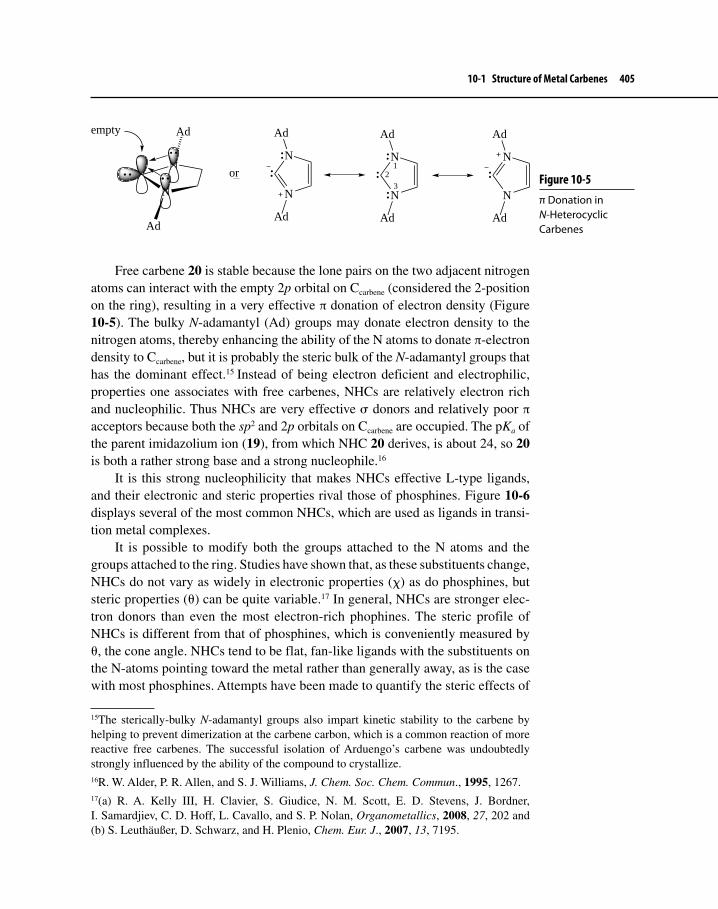
10-1 Structure of Metal Carbenes 405
Free carbene 20 is stable because the lone pairs on the two adjacent nitrogen atoms can interact with the empty 2p orbital on Ccarbene (considered the 2-position on the ring), resulting in a very effective π donation of electron density (Figure 10-5). The bulky N-adamantyl (Ad) groups may donate electron density to the nitrogen atoms, thereby enhancing the ability of the N atoms to donate π-electron density to Ccarbene, but it is probably the steric bulk of the N-adamantyl groups that has the dominant effect.15 Instead of being electron deficient and electrophilic, properties one associates with free carbenes, NHCs are relatively electron rich and nucleophilic. Thus NHCs are very effective σ donors and relatively poor π acceptors because both the sp2 and 2p orbitals on Ccarbene are occupied. The pKa of the parent imidazolium ion (19), from which NHC 20 derives, is about 24, so 20 is both a rather strong base and a strong nucleophile.16
It is this strong nucleophilicity that makes NHCs effective L-type ligands, and their electronic and steric properties rival those of phosphines. Figure 10-6 displays several of the most common NHCs, which are used as ligands in transi-tion metal complexes.
It is possible to modify both the groups attached to the N atoms and the groups attached to the ring. Studies have shown that, as these substituents change, NHCs do not vary as widely in electronic properties (χ) as do phosphines, but steric properties (θ) can be quite variable.17 In general, NHCs are stronger elec-tron donors than even the most electron-rich phophines. The steric profile of NHCs is different from that of phosphines, which is conveniently measured by θ, the cone angle. NHCs tend to be flat, fan-like ligands with the substituents on the N-atoms pointing toward the metal rather than generally away, as is the case with most phosphines. Attempts have been made to quantify the steric effects of
15The sterically-bulky N-adamantyl groups also impart kinetic stability to the carbene by helping to prevent dimerization at the carbene carbon, which is a common reaction of more reactive free carbenes. The successful isolation of Arduengo’s carbene was undoubtedly strongly influenced by the ability of the compound to crystallize.16R. W. Alder, P. R. Allen, and S. J. Williams, J. Chem. Soc. Chem. Commun., 1995, 1267.17(a) R. A. Kelly III, H. Clavier, S. Giudice, N. M. Scott, E. D. Stevens, J. Bordner, I. Samardjiev, C. D. Hoff, L. Cavallo, and S. P. Nolan, Organometallics, 2008, 27, 202 and (b) S. Leuthäußer, D. Schwarz, and H. Plenio, Chem. Eur. J., 2007, 13, 7195.
Figure 10-5 π Donation in N-Heterocyclic Carbenes
N
Ad
Ad
N
empty
N
N
Ad
Ad
N
N
Ad
Ad
N
N
Ad
Ad
or1
23

406 Chapter 10 Transition Metal–Carbene and –Carbyne Complexes
NHCs, but work still remains before a definitive, simple-to-use, and universally-accepted parameter like θ is available to chemists.18
The bonding picture for NHC–metal complexes is rather different than exists for Fischer or Schrock complexes. Calculations show that the amount of back-bonding from the metal to the ligand is quite small, and that bonding is almost entirely due to σ-donation from the relatively electron rich Ccarbene.19 As such, most consider the bond between ligand and metal to be closer to a single bond rather than a formal double bond, and NHC–metal complexes are typically drawn with an M−Ccarbene single bond. According to the resonance treatment, which was discussed in Section 10-1, the structure of NHC–metal complexes would be most closely approximated by structure 12.
NHC–transition metal complexes find increasing use in the field of organic synthesis. Structure 21, known as a second-generation Grubbs catalyst used in
18See Footnote 17a.19G. Frenking, M. Solà, and S. F. Vyboishchikov, J. Organomet. Chem., 2005, 690, 6178.
Figure 10-6 Some Important N-Heterocyclic Carbenes
N NRR
N NRR
N NRR
Typical R groups: Isopropyl (i-Pr)Adamantyl (Ad)Cyclohexyl (Cy)tert-Butyl (t-Bu)
Mesityl (Mes):
Me
Me
Me
N
N NRR
R
X X
X= H, F, OMe
Exercise 10-1 Why is varying substituents on NHCs, either the groups attached to the N-atoms or the groups attached to the ring, less likely to cause large variation in χ than is the case with phosphines?

10-2 Synthesis of Metal Carbene Complexes 407
reactions that form C=C bonds, is perhaps the most famous of these compounds.20 Note that this catalyst is both an NHC-complex and an alkylidene. We will con-sider the role of compound 21 and related complexes in C=C bond formation in Chapter 11.
CRuCl
Cl
PCy3
NN
H
PhMe
Me
Me
Me
Me
Me
21
10-2 SYNTHESIS OF METAL CARBENE COMPLEXES
10-2-1 Fischer (Electrophilic) Carbene ComplexesThere are numerous synthetic routes to Fischer carbene complexes.21 We may classify these routes as fundamentally of two kinds:
A. Replacement or modification of an existing non-carbene ligand.B. Modification of an existing carbene ligand.
In this section, our discussion focuses on the type A pathway. Because modifica-tion of an existing carbene ligand to produce a new carbene is an example of a type of reaction carbenes may undergo, we will postpone discussion of type B reactions until Section 10-3.
Following are a few general methods for the preparation of Fischer-type car-bene complexes.
Formation of Carbene Complexes by Nucleophilic Attack at a Carbonyl LigandEquation 10.6 shows the original work of Fischer and Maasböl in preparing the first reported metal–carbene complex. Attack by the carbanion (see equation 8.28
20M. Scholl, S. Ding, C. W. Lee, and R. H. Grubbs, Org. Lett., 1999, 1, 953.21Several good reviews exist that describe synthetic routes to electrophilic carbene complexes. These include F. J. Brown, Prog. Inorg. Chem., 1980, 27, 1; K. H. Dötz, et al., Transition Metal Carbene Complexes, Verlag Chemie: Deerfield Beach, FL, 1983, pp. 1-68; and M. A. Gallop and W. R. Roper, Adv. Organomet. Chem., 1986, 25, 121.

408 Chapter 10 Transition Metal–Carbene and –Carbyne Complexes
in Section 8-2-1) at the carbon atom of a carbonyl ligand, followed by methyla-tion, yields the corresponding carbene.
W(CO)6RLi
(CO)5W C
O− Li+
R
(CO)5W C
OMe
R
(CO)5W C
OH
R
Me3O+ BF4−
MeOH
H+
H2OR = Me, Ph
10.6
This is a versatile reaction because one may use different attacking carbanionic groups (RLi, R = alkyl, aryl, or silyl) and different O-alkylating agents. Carbonyl complexes of several different metals, such as Mo, Mn, Rh, Fe, and Ni, undergo this transformation.
Formation of Cyclic Carbene ComplexesThe cyclic carbene complex (23) formed in equation 10.722 is analogous to the original Fischer-type carbene complex. The ring, however, offers an added complexity that has utility in the realm of organic synthesis.
(CO)nM Br
CO
I−(CO)n−1M
I
O
Br (CO)n−1M
I
O
M = Mo, n = 2M = Fe, n = 1
23+ Br−
CO
10.7
The first step involves formation of an anionic acyl complex, which then under-goes intramolecular SN2 displacement of bromide to yield 23.
22H. Adams, N. A. Bailey, M. Grayson, C. Ridgway, A. J. Smith, P. Taylor, M. J. Winter, and C. E. Housecroft, Organometallics, 1990, 9, 2621.
Exercise 10-2 Propose a synthetic route to 22, a silicon-containing carbene.
(CO)5Mo C
OEt
SiPh322

10-2 Synthesis of Metal Carbene Complexes 409
Synthesis of N-Substituted Carbene ComplexesNitrogen often appears attached directly to carbon in Fischer-type carbene complexes. Equations 10.823 and 10.924 provide two examples of N-substituted carbene complex synthesis. The first procedure involves attack by the amide on one of the carbonyls (analogous to equation 10.6) followed by alkylation.
Cr(CO)6 (CO)5Cr C
OEt
NEt2
1) Et2NLi
2) Et3O+ BF4
−
10.8
Et3P(Br)2Pt C N Me
Et3P(Br)2Pt C N Me
Isonitrile form
R Y H Y = O, S, N
Et3P(Br)2Pt C
NMe
Y H
R
Et3P(Br)2Pt C
NMe
Y R
H
10.9
The second case involves attack of R−Y−H on the electron-deficient carbon of the isonitrile ligand, followed by proton transfer. It is adjustable with regard to nucleophile since amines (Y = N), unhindered alcohols (Y = O), and thiols (Y = S) add to the isonitrile carbon to form the corresponding diamino, aminoalkoxy, and aminothio carbenes. Isonitrile complexes of several different metals undergo this reaction, although Pd and Pt complexes have been the most thoroughly investigated.25
10-2-2 Schrock (Nucleophilic) CarbenesCompared with electrophilic carbene complexes, relatively few procedures exist for preparing nucleophilic carbene complexes (alkylidenes).26 Generally, these
23E. O. Fischer and H.-J. Kollmeier, Angew. Chem. Int. Ed. Eng., 1970, 9, 309.24E. M. Badley, J. Chatt, and R. L. Richards, J. Chem. Soc., A, 1971, 21.25H. Fischer, In The Chemistry of the Metal-Carbon Bond, F. R. Hartley and S. Patai, Eds., Wiley–Interscience: New York, 1982, Vol. 1, p. 185.26For a recent survey on the synthesis of high-valent metal–alkylidene and –alkylidyne com-plexes, see R. R. Schrock, Chem. Rev., 2002, 102, 145.
What is the mechanism of the first step in equation 10.7? Exercise 10-3

410 Chapter 10 Transition Metal–Carbene and –Carbyne Complexes
complexes are more reactive than corresponding Fischer carbene complexes because of the lack of stabilizing heteroatom substituents. Obvious precursors for alkylidenes ought to be alkyl ligands; loss of an α-H would give the correspond-ing carbene, as shown in equation 10.10.
LnM CHR
H:B−
LnM CHR + BHα
10.10
One problem with this approach is the ever-present, rapid, competing side reaction of β-elimination (Section 8-1-2). As we shall see, α-elimination is indeed used to produce alkylidenes, but the circumstances of this reaction are unique. Other approaches that we will discuss include decomposition of bridged alkylidenes and direct attack of a free carbene precursor on a metal.
Loss of the � HydrogenThe early work of Schrock and co-workers27 involved the synthesis and character-ization of Group 5 alkylidenes involving Ta and Nb. Scheme 10.1 describes some of the first preparations of alkylidenes. The key reaction here is loss of a proton attached to Cα to form an M=C bond (α-elimination). In all cases, β-elimination is blocked because of the lack of a β-hydrogen.
Sequence 1. The first sequence of reactions in the scheme begins when 10-electron 24 reacts with neopentyllithium to give the tetraalkylchloro complex 25 via a ligand substitution reaction. Intermediate 25 either reacts directly with additional neo-pentyllithium to give 27 [via (neopentyl)5M] or it decomposes to the chloroalky-lidene complex 26, which then reacts with another equivalent of neopentyllithium, replacing the chloro group with a neopentyl ligand. Regardless of the pathway, the reaction is remarkable because somehow an alkane (2,2-dimethylpropane) and an alkylidene form as products. Equation 10.11 shows how this may occur.
(Me3CCH2)M
CH2
CCl
H
H (Me3CCH2)M CH
Cl
+ CH3
2526
via
(Me3CCH2)M
CH2
CCl
H
H
38
10.11
27For a good summary of this work, see R. R. Schrock, Acc. Chem. Res., 1979, 12, 98, and references therein.

10-2 Synthesis of Metal Carbene Complexes 411
Scheme 10.1 Preparation of Group 5 Schrock Carbene Complexes
M
Cl
Cl
ClM(CH2CMe3)4LiCH2CMe3
Cl(Me3CCH2)2M(Me3CCH2)3MLiCH2CMe3
LiCH2CMe3
27 26
25
24
Sequence 1:
M = Nb, Ta
Sequence 2:
Cl3(Me3CCH2)2MTlCp
M
ClCl
TlCpM
Cl
PMe3
MMe3P
Cl
Cl
MCl PMe3
Cl
Cl
Cl
Ta
CH2Ph
PhCl2(PhCH2)3Ta2 TlCp
Sequence 3:
Cl2Me3Ta2 TlCp
Cp2Me3TaPh3C+ BF4
−[Cp2Me2Ta]+ BF4
− + MeCPh3
Ta
CH3
CH2
2829
30
31
32
33
34 35 36
37
Ph3P=CH2
α
β
The driving force for the reaction clearly must be the reduction of steric hin-drance that occurs upon expulsion of one of the sterically-demanding neopentyl groups. Protons attached at the α-position of the neopentyl groups also may be somewhat agostic (structure 38; see Section 6-2-3), because the Group 5 metal is

412 Chapter 10 Transition Metal–Carbene and –Carbyne Complexes
electron deficient [M(V) and d0]. If so, the α C−H bond would already be weak-ened, making hydrogen transfer to alkyl more favorable energetically.
Sequence 2. Treatment of the dineopentyl complex (28) with cyclopentadienylide ion displaces one of the chloro groups with a Cp ligand with simultaneous expul-sion of alkane to give 29. Again, the steric bulkiness of the Cp group actuates the loss of alkane by α-elimination. A second Cp−Cl ligand exchange results in formation of 30 (an 18-e– complex). Conversion of 32 to 33 is analogous and demonstrates that the reaction also occurs with a benzyl ligand.
Conversion of 28 to 31 is possible because of the steric and electronic prop-erties of PMe3. The dimeric 31 contains 14 electrons/metal atom, and its elec-tron deficiency is stabilized by the presence of the phosphine, a strong σ donor. The phosphine also has sufficient steric bulk so that, as it attaches to the metal, steric hindrance increases sufficiently to allow intramolecular α-elimination to occur. An X-ray structure of 31 (shown partially as structure 39, M = Ta) is inter-esting.28 It shows that the bond angle involving the metal, α-, and β-carbons is 161.2o, much higher than the expected 120o for the sp2 alkylidene α carbon. The bond angle involving metal, Ccarbene, and attached hydrogen is 84.8o—significantly less than 120o! The bond distance between Ta and C is only 189.8 pm, consid-erably shorter than Ta=C bond distances in other Ta–carbene complexes (aver-age distance = 204 pm). Structure 40 illustrates a possible explanation for these observations. Steric hindrance apparently forces the M−Ccarbene−Cβ bond angle to increase beyond that expected for an sp2-hybridized carbon. The electron defi-ciency at Ta (14 e–) provides an opportunity for extra electron density to be sup-plied through an agostic interaction between the α-hydrogen and an empty d orbital on the metal. In effect, the bond between Ta and carbon is a three-center, six-electron bond.29
Ta
Me3P Cl
ClC
39
H θ
φθ = 84.8o
φ = 161.2o
Ta C
H
40
28A. J. Schultz, J. M. Williams, R. R. Schrock, G. A. Rupprecht, and J. D. Fellmann, J. Am. Chem. Soc., 1979, 101, 1593.29For a recent review on agostic interactions of early- to mid-transition metal methylidenes, see L. Andrews and H.-G. Cho, Organometallics, 2006, 25, 4040.

10-2 Synthesis of Metal Carbene Complexes 413
Sequence 3. The last reaction sequence in Scheme 10.1 details the preparation of a methylidene complex (37) starting with 34. Attempts to observe α-elimination analogous to the reactions described above in 35 were unsuccessful; only decom-position was observed. Electrophilic abstraction of a methyl group from 35 using trityl cation (Ph3C+), however, produced tantalonium salt 36. Schrock realized here the analogy between the tantalonium salt and phosphonium salts, the precur-sors to ylides in the Wittig reaction. Protons attached to the α-carbon in phos-phonium salts are relatively acidic and may be abstracted with bases of varying strength depending upon the nature of other substituents attached to the α-carbon. Schrock reasoned that a methyl proton (the α-proton) in 36 could be removed by a strong base. Use of a phosphorus ylide,30 (CH3)3P=CH2, as well as other bases successfully confirmed his prediction, yielding methylidene 37 as a pale-green crystalline solid.
A more recent example involving α-elimination is shown in equation 10.12. Here, Ag(I) is used to induce alkylidene formation by first oxidizing Ti to a d0 state, which is followed by α-elimination and then RE of alkane. Similar chemis-try occurs with vanadium and niobium complexes.31
TiCH2
N
NMe
Me
Ar
Ar
t-Bu
t-Bu
AgOTfTi
OTfN
NMe
Me
Ar
Ar
t-Bu
+ CH3−CMe3 + Ag(0)
10.12
Decomposition of Bridged Alkylidene ComplexesAnother approach to alkylidenes involves Group 4 metals, particularly Zr. Treatment of a vinyl Cp2Zr complex (41) with diisobutylaluminum hydride gives bridged alkylidene 42 where the alkylidene group is shared (μ-bonding) between Zr and Al (equation 10.13).32 The dialkylaluminum hydride’s Al−H bond adds across the vinyl C=C in a manner analogous to hydroboration such that the chloro ligand (attached to Zr) can act as a Lewis base complementary to electron- deficient Al.
30See Footnote 11.31F. Basuli, B. C. Bailey, L. A. Watson, J. Tomaszewski, J. C. Huffman, and D. J. Mindiola, Organometallics, 2005, 24, 1886; for a review of oxidatively induced alkylidene formation involving Ti and other early transition metals, see D. J. Mindiola, Acc. Chem. Res., 2006, 39, 813.32F. W. Hartner Jr. and J. Schwartz, J. Am. Chem. Soc., 1981, 103, 4979.

414 Chapter 10 Transition Metal–Carbene and –Carbyne Complexes
Cp2ZrCH=CHCH3
Cl AlH
Cp2Zr
Cl
Al
CH
Et
41 42
10.13
Once 42 forms, treatment first with Ph3P and then with hexamethylphosphor-amide (HMPA) results in the formation of alkylidene 43 (phosphines are good ligands for electron-deficient Zr(IV) complexes such as 42). First the phosphine binds to Zr, and then HMPA (a highly polar molecule and a Lewis base) attacks Al (equation 10.14).33 Fragmentation results in formation of the alkylidene and an HMPA–Al complex.
Cp2Zr
Cl
Al
CH
Et
42
Ph3PCp2Zr
Cl
Al
CH
Et:O=P(NMe2)3
Cp2(PPh3)Zr=CH−Et43
+
HMPA-AlCl(i-Bu)2Ph3P
10.14
One of the most famous Ti carbene complexes is methylidene 44. Although 44 probably occurs fleetingly as an intermediate in Schrock carbene reactions, it is too reactive to be isolated or observed spectroscopically. Two related com-pounds, however, have been synthesized:34 Cp2TiCH2(PEt3), in which the phos-phine donates electrons to Ti to stabilize the complex, and the immediate precursor to 44, known as Tebbe’s reagent (45, equation 10.1535).
CH2Ti
44
33F. W. Hartner Jr., J. Schwartz, and S. M. Clift, J. Am. Chem. Soc., 1983, 105, 640.34S. H. Pine, Org. Reactions, 1993, 43, 1.35F. N. Tebbe, G. W. Parshall, and G. S. Reddy, J. Am. Chem. Soc., 1978, 100, 3611.

10-2 Synthesis of Metal Carbene Complexes 415
Ti
45
CAl
Cl
Me
Me
H H
Cp2TiCl2 + 2 AlMe3 CH4 +
10.15
Equation 10.15 provides another example of the use of Al compounds to form bridging alkylidenes, providing stabilization for the very reactive Group 4 car-bene complexes. Later in Chapter 10 (Section 10-3-2), we shall encounter some of the synthetically useful chemistry of Tebbe’s reagent.
Direct Attack of a Free Carbene Precursor onto a MetalDiazoalkanes, RR'C=N=N (R,R' = H, alkyl, aryl), serve as precursors to free carbenes through thermal- or photochemical-induced loss of N2, according to equation 10.16.
C N NR'
R
C N NR'
R
hνC
R'
R+ N N
10.16
Although transition metal complexes do not usually react directly with free carbenes (with the exception of the formation of NHC–metal complexes, Section 10-2-3), low-valent Group 7 to 9 metal complexes in particular react with diazoalkanes to produce alkylidenes. Equation 10.17 shows a general example of this reaction. The complex must either be unsaturated or possess a labile L-type ligand so that the reac-tion can occur. The intermediate in this reaction is unlikely to be a free carbene.
LnM + RCHN2 ∆ Ln−1M C
R
H
+ L + N2 (g)
10.17
A good example of this type of metal carbene synthesis appears in equation 10.18, which shows that a variety of diazoalkanes react with the Os complex.36 We will encounter more diazoalkane chemistry in Section 10-3-3.
36A. F. Hill, W. R. Roper, J. M. Waters, and A. H. Wright, J. Am. Chem. Soc., 1983, 105, 5939; see also M. A. Gallop and W. R. Roper, Adv. Organomet. Chem., 1986, 25, 121–198, especially pp. 156–159.

416 Chapter 10 Transition Metal–Carbene and –Carbyne Complexes
OsCl(NO)(PPh3)3
RCHN2Cl(NO)(PPh3)2Os C
R
H
+ N2 (g) + PPh3
R = H, Me, p-tolyl 10.18
10-2-3 Synthesis of N-Heterocyclic Carbene ComplexesThere are many approaches to the synthesis of NHC–metal complexes, and a few of these will be discussed in this section. Among the most commonly-used strategies for producing these complexes are the following: 1) inserting a metal into the C=C bond of an NHC dimer, 2) allowing a metal complex to react with a protected form of the NHC, 3) generating an NHC in situ via a Brønsted–Lowry acid–base reaction in the presence of a metal complex, and 4) directly combining a free NHC with a metal complex.37
Metal Insertion into the C=C Bond of an NHC DimerProducing NHC–metal complexes by C=C scission of an NHC dimer is one method that is fairly general and interesting mechanistically. Equation 10.19 indi-cates the overall pathway to complex 46.38
N
N
N
N
R
R
R
R
R = Me, Et
Mo(CO)6 +
N
N
(CO)5Mo
R
R
+
N
N
R
R46
10.19
A plausible mechanism for this reaction is shown in Scheme 10.2, which consists of a stepwise sequence of several fundamental types of organometallic reactions.
37A fifth method, which now sees increasing use, involves first formation of a Ag–NHC complex, which then undergoes reaction with another metal complex (typically involving a Group 10 metal). The NHC ligand is transferred from the Ag complex to the other metal. For a review of this method and the others mentioned above, see E. Peris, Top. Organomet. Chem., 2007, 21, 83 and J. C. Garrison and W. J. Youngs, Chem. Rev., 2005, 105, 3978.38For a review of this method for formation of NHC–metal complexes, see M. F. Lappert, J. Organomet. Chem., 1988, 358, 185.
Exercise 10-4 Propose a synthesis of (NO)(PMe3)3Ir=C(H)(Me) starting with an appropriate Ir complex.

10-2 Synthesis of Metal Carbene Complexes 417
Beside complexes of the Group 6 triad, Ru, Os, and Ir carbonyl complexes also undergo this reaction.
Reaction of Protected NHCs with Metal ComplexesNHC precursors 47a and 47b may be used to generate the corresponding free carbene because an alcohol or chloroform readily eliminates from carbon (equa-tion 10.20). Chemists can synthesize and isolate these precursors before allow-ing them to react with metal complexes or simply generate them in situ in the presence of the metal complex.
N NR R
H Y
MLn N NR R+ H−Y + L
MLn−1
47a: Y = OR' (R' = alkyl)47b: Y = CCl3
10.20
Equation 10.21 shows how Grubbs and co-workers used this method to gener-ate compound 21, the second-generation catalyst mentioned earlier. Here, the
Scheme 10.2 A Possible Mechanistic Pathway for Alkene Scission
N
N
N
N
R
R
R
R
Mo(CO)6 +
CON N
N N
RR
RR
(CO)5Mo
CO
N N
N N
RR
RR
(CO)4Mo
CO
N
N
(CO)5Mo
R
R+
N
N
R
R
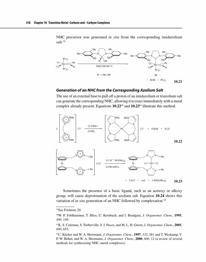
418 Chapter 10 Transition Metal–Carbene and –Carbyne Complexes
NHC precursor was generated in situ from the corresponding imidazolium salt.39
CRuCl
Cl
PCy3
NN
H
PhMe
Me
Me
Me
Me
21
CRuCl
Cl
PCy3H
Ph
PCy3
NN
Me
Me
Me
Me
Me
Me
ORH
R = t-Bu, Me
PhH/THF/80 oC
+ ROH + PCy3
Me
10.21
Generation of an NHC from the Corresponding Azolium SaltThe use of an external base to pull off a proton of an imidazolium or triazolium salt can generate the corresponding NHC, allowing it to react immediately with a metal complex already present. Equations 10.2240 and 10.2341 illustrate this method.
N
NMe
N
NMe
2 I−21) 4 BuLi
2) PdI2
N
NMe
N
NMe
N
MeN
N
MeN
Pd 2 I− + 4 BuH + 4 LiI
10.22
Fe
N
N
N
N
t-Bu
t-Bu
2 Cl−1) 2 K+ −N(SiMe3)2
2) Pd(cod)Cl2
Fe
N
N
N
N
t-Bu
t-Bu
Pd ClCl
+ 2 KCl + cod + 2 HN(SiMe3)2
10.23
Sometimes the presence of a basic ligand, such as an acetoxy or alkoxy group, will cause deprotonation of the azolium salt. Equation 10.24 shows this variation of in situ generation of an NHC followed by complexation.42
39See Footnote 20.40W. P. Fehlhammer, T. Bliss, U. Kernbach, and I. Brudgam, J. Organomet. Chem., 1995, 490, 149.41K. S. Coleman, S. Turberville, S. I. Pascu, and M. L. H. Green, J. Organomet. Chem., 2005, 690, 653.42C. Köcher and W. A. Herrmann, J. Organomet. Chem., 1997, 532, 261 and T. Weskamp, V. P. W. Böhm, and W. A. Herrmann, J. Organomet. Chem., 2000, 600, 12 (a review of several methods for synthesizing NHC–metal complexes).

10-3 Reactions of Metal–Carbene Complexes 419
RhO
Et
2
+
N
N
CHPh2
CHPh2
EtOH/25 oCRh
Cl
N
N
CHPh2
Ph2CH
+ EtOH
10.24
Reaction of a Free NHC with a Metal ComplexBecause free NHCs bind so strongly to a metal, it is not necessary to use an excess amount of these ligands to make NHC–metal complexes. This contrasts with the synthesis of metal phosphine complexes, where often an excess of the ligand is required for success. There are numerous examples of simple combina-tion of the free carbene and a suitable metal complex. Equation 10.25 illustrates one example.43
RhCl
2NN+ 2 2 Rh
Cl
N
N
10.25
Because back-donation of electron density to ligands is not likely with high-valent, early transition metals, it seems reasonable that complexes between such metals and strong σ donor ligands such as NHCs, which are not good π acceptors, could be synthesized. Synthesis of such complexes is indeed possible, as equation 10.26 demonstrates.44
N
NTiCl4
N
N
TiCl4
10.26
10-3 REACTIONS OF METAL–CARBENE COMPLEXESTransition metal–carbene complexes possess several sites where nucleophiles, electrophiles, oxidizing agents, and protic acids might attack; these are depicted
43See Footnote 17a.44N. Kuhn, T. Kratz, D. Blaser, and R. Boese, Inorg. Chim. Acta, 1995, 238, 179.

420 Chapter 10 Transition Metal–Carbene and –Carbyne Complexes
in Figure 10-7. In the following discussion, we will focus primarily on the reaction of nucleophiles at Ccarbene (site a), at the substituents attached to Ccarbene (sites b and c), and at the metal (site d). We will also discuss reactions of electrophiles at sites a and d.
A Caveat Regarding the Reactivity of Metal Carbenes
As mentioned in Section 10-1, it is convenient to classify carbene complexes on the basis of their reactivity at Ccarbene (site a). Fischer carbene complexes tend to undergo nucleophilic attack at this position, whereas Schrock carbene complexes (alkylidenes) undergo attack by electrophiles at site a. Although this is a useful generalization, applicable in most cases, there are several exceptions to this pattern of reactivity. For example, we shall encoun-ter alkylidenes that undergo attack by nucleophiles at Ccarbene, indicating that there is a spectrum of reactivities possessed by metal–carbene complexes. Metal oxidation state, overall charge on the complex, position of the metal in the periodic table, and electronic properties of ligands all influence the reactivity of the metal carbene such that the line of demarcation between the reactivity patterns of Fischer and Schrock carbene complexes is indistinct at times.
10-3-1 Nucleophilic Reactions45
Site aDespite the caveat expressed above, the most common reaction that Fischer car-bene complexes undergo is attack by a nucleophile at Ccarbene. It is interesting that such reactivity should occur, because partial charge calculations typically indicate a higher positive charge at the carbon in CO ligands than at Ccarbene.46 The key to understanding the electrophilicity of these complexes, however, is the
45For a recent, comprehensive discussion on the mechanism of reactions of Fischer carbene complexes, see C. F. Bernasconi, Adv. Phys. Org. Chem., 2002, 37, 137.46T. F. Block, R. F. Fenske, and C. P. Casey, J. Am Chem. Soc., 1976, 98, 441 and N. M. Kostic and R. F. Fenske, Organometallics, 1982, 1, 974.
Figure 10-7 Reactive Sites of Transition Metal–Carbene Complexes
LnM C
X
Y
a
d
b
c

10-3 Reactions of Metal–Carbene Complexes 421
application of frontier molecular orbital theory. Electrophilic carbene complexes usually have a relatively low-energy LUMO with a large lobe on Ccarbene and a much smaller lobe on M. Thus, as the nucleophile approaches the carbene com-plex, there is a much better bonding overlap between the HOMO of the nucleo-phile and the carbene LUMO at Ccarbene than at the metal. Figure 10-8 illustrates this concept for attack on (CO)5Cr=C(H)(OH).
It is noteworthy that the LUMO of a Fischer type carbene resembles the LUMO (determined using semi-empirical MO theory) of a typical ester such as methyl ace-tate (Figure 10-9a) or a ketone such as acetone (Figure 10-9b). In fact, the analogy between Fischer carbenes and carbonyl compounds should be useful to readers already familiar with organic chemistry. Indeed, the chemistry of these two types of compounds, seemingly so different in structure, is similar in several ways.
Equation 8.29 (Section 8-2-1 and reproduced below) already has provided an illustration of nucleophilic attack on a Fischer-type carbene and the analogy with aminolysis.
(CO)5Cr C
OCH3
Ph
+ N R
H
H
C NH2R
OCH3
Ph
(CO)5Cr (CO)5Cr C
NHR
Ph
+ CH3OH
(CO)5Cr C
NHR
Ph48
The driving force for the exchange of groups at Ccarbene is formation of a C−N bond that is stronger than C−O. Structure 48 (comparable to resonance contribu-tor 11 in Section 10-1), which shows considerable double bond character between Ccarbene and the heteroatom, takes on increasing importance when nitrogen is
Figure 10-8 Frontier Orbital Interaction in Nucleophilic Attack on Fischer Carbene Complexes
LnCr CH
OH
Nuc (HOMO)
(LUMO)
8.29

422 Chapter 10 Transition Metal–Carbene and –Carbyne Complexes
present instead of oxygen because a positively-charged nitrogen atom is more stable than the correspondingly charged oxygen.
Fischer measured the kinetics of carbene aminolysis (specifically for the reaction shown in equation 8.29) and derived a rate law according to the following:47
Rate = k[MeNH2][HX][Y][carbene].where HX = a proton donor e.g., the amine or a protic solvent Y = a proton acceptor e.g., the amine or solvent
47B. Heckl, H. Werner, and E. O. Fischer, Angew. Chem. Int. Ed. Eng., 1968, 7, 817 and H. Werner, E. O. Fischer, B. Heckl, and C. G. Kreiter, J. Organomet. Chem., 1971, 28, 367.
Figure 10-9 The LUMOs of (a) Methyl Acetate and (b) Acetone
a
b
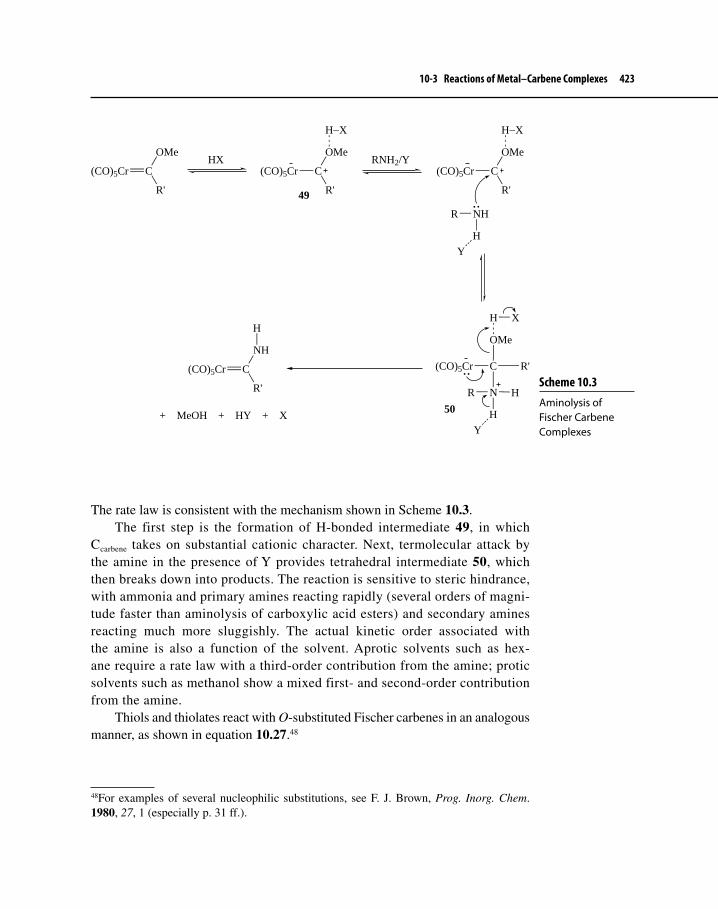
10-3 Reactions of Metal–Carbene Complexes 423
The rate law is consistent with the mechanism shown in Scheme 10.3.The first step is the formation of H-bonded intermediate 49, in which
Ccarbene takes on substantial cationic character. Next, termolecular attack by the amine in the presence of Y provides tetrahedral intermediate 50, which then breaks down into products. The reaction is sensitive to steric hindrance, with ammonia and primary amines reacting rapidly (several orders of magni-tude faster than aminolysis of carboxylic acid esters) and secondary amines reacting much more sluggishly. The actual kinetic order associated with the amine is also a function of the solvent. Aprotic solvents such as hex-ane require a rate law with a third-order contribution from the amine; protic solvents such as methanol show a mixed first- and second-order contribution from the amine.
Thiols and thiolates react with O-substituted Fischer carbenes in an analogous manner, as shown in equation 10.27.48
48For examples of several nucleophilic substitutions, see F. J. Brown, Prog. Inorg. Chem. 1980, 27, 1 (especially p. 31 ff.).
Scheme 10.3 Aminolysis of Fischer Carbene Complexes
(CO)5Cr C
OMe
R'
HX(CO)5Cr C
OMe
R'
H−X
RNH2/Y(CO)5Cr C
OMe
R'
H−X
R NH
H
Y
(CO)5Cr C
OMe
R'
H
R N
H
Y
H
X
(CO)5Cr C
NH
R'
H
+ MeOH + HY + X
49
50

424 Chapter 10 Transition Metal–Carbene and –Carbyne Complexes
(CO)5M
OMe
R
+ R'SH
SR'
R
+ MeOH
M = Cr, W; R = Me, Ph; R' = Me, Et, Ph
C (CO)5M C
10.27Organolithium compounds can serve as sources of carbon nucleophiles
to drive substituent group exchange at Ccarbene—thus providing a route to alkylidenes— according to equation 10.28.49 The reaction is limited to lithium reagents that do not possess H atoms attached to the carbon bonded to Li; other-wise, rearrangement (equation 10.29) occurs to give an alkene.50
(CO)5W C
OMe
Ph
PhLi−78 oC
(CO)5W C
OMe
Ph
PhHCl
−78 oC(CO)5W C
Ph
Ph
+ MeOH
10.28
(CO)5W C
OMe
Ph
1) MeLi/−78 oC2) HCl/−78 oC
(CO)5W C
H2C
Ph
H
+ MeOH
25 oC(CO)5W
Ph
10.29
Sites b and cIn organic chemistry, carbonyl compounds can undergo reaction at the carbon next to a C=O group (the α carbon) as well as nucleophilic attack on the car-bonyl carbon. The electron-withdrawing nature of the carbonyl group renders protons at the α-position acidic. In Fischer carbene complexes, hydrogen atoms α to Ccarbene are analogously acidic. Such reactivity is synthetically useful. Loss of an α-hydrogen generates a carbanion analogous to an enolate ion that then undergoes reaction with electrophiles such as D+, R+, or R−C=O+, the last two affording routes to new carbenes. Equation 10.3051 shows specific deuteration, 10.3152 alkylation using allyl bromide, and 10.3253 an aldol condensation.
49C. P. Casey and T. J. Burkhardt, J. Am. Chem. Soc., 1973, 95, 5833.50C. P. Casey, L. D. Albin, and T. J. Burkhardt, J. Am. Chem. Soc., 1977, 99, 2533.51C. P. Casey, R. A. Boggs, and R. L. Anderson, J. Am. Chem. Soc., 1972, 94, 8947.52C. P. Casey, “Metal–Carbene Complexes in Organic Synthesis,” in Transition Metal Organometallics in Organic Synthesis, H. Alper, Ed., Academic Press: New York, 1976, Vol. 1., pp. 189–233.53C. P. Casey and W. R. Brunsvold, J. Organomet. Chem., 1974, 77, 345.

10-3 Reactions of Metal–Carbene Complexes 425
C
OMe
CH3
1) BuLi
2) DClC
OMe
(CO)5Cr (CO)5Cr
CH2−D 10.30
C
1) BuLi
2)
O
Br
C
O
(CO)5Cr (CO)5Cr
10.31
(CO)5Cr C
OMe
CH3
1) BuLi
2) PhCHO(CO)5Cr C
OMe
Ph
O (CO)5Cr C
OMe
Ph
Protonation followedby elimination of Η2Ο
10.32
Site dCarbonyls are the most common ligand found in electrophilic carbene complexes. They may be exchanged readily for other ligands, usually by a dissociative sub-stitution pathway (see Section 7-1-3). Equation 10.33 describes studies involving ligand substitution with phosphines, perhaps the most typical nucleophile used. Interestingly, the reaction shows two mechanistic pathways: (1) dissociative substi-tution of CO by PR3 (SN1-like) and (2) rate-determining attack by PR3 at Ccarbene to produce a tetrahedral intermediate (the phosphorus analogue of structure 50), which is followed by rearrangement to the product shown in equation 10.33 (SN2-like).54
54H. Fischer, E. O. Fischer, C. G. Kreiter, and H. Werner, Chem. Ber., 1974, 107, 2459; see also Footnote 45.
Propose a synthesis of spirocyclic carbene complex B starting from A.
(CO)5W C
O(CO)5W C
O
A B
Exercise 10-5

426 Chapter 10 Transition Metal–Carbene and –Carbyne Complexes
(CO)5M C
R'
OMePR3 cis- + trans-(CO)4(R3P)M C
OMe
R'
M = Cr, Mo, W; R' = Ph, Me; R = Me, Et, Bu, Ph 10.33
It is worth noting that the presence of a carbene ligand in Cr carbonyl complexes provides a kinetic stimulus toward CO dissociation, especially compared with non-carbene analogs. Table 10-2 illustrates the effect of the carbene ligand on the tendency for CO to dissociate in Cr complexes according to equation 10.34.
The driving force for such high CO ligand lability probably rests with the ability of the heteroatom attached to Ccarbene to donate electrons by resonance to the metal, which becomes electron deficient upon loss of CO.
(CO)5CrL + PCy3Decane/59 oC
(CO)4CrL(PCy3) + CO
10.34
10-3-2 Electrophilic ReactionsCertain metal–carbene complexes, especially alkylidenes involving the early- transition metals, behave as nucleophiles, reacting with electron-deficient spe-cies at Ccarbene. Figure 10-10 illustrates the HOMO (determined using DFT) of F3Nb=CH2, a hypothetical Schrock-type carbene. Note the high electron den-sity at Ccarbene, indicating a position readily susceptible to attack by electrophiles. Resonance theory also indicates that Schrock-type metal carbenes possess sub-stantial negative charge density at Ccarbene, with structures 9 and 12 (Section 10-1) having the greatest contribution to the overall structure. We again emphasize that it is useful to think of alkylidenes as behaving like phosphorus ylides (see Footnote 11).
Table 10-2a Rate Parameters for Ligand Dissociation of Cr Complexes
L krel ΔH (kcal/mol)
=C(OMe)(Me) 240,000 27.6CO 11 38.7P(Cy)3
b 1 40.4
aF. J. Brown, Prog. Inorg. Chem. 1980, 27, 1 (especially p. 45).bCy = cyclohexyl.

10-3 Reactions of Metal–Carbene Complexes 427
In our discussion we will focus on electrophilic reactions that occur at Ccarbene, site a. Equations 10.35, 10.36, and 10.37 provide some examples of alkylidene chemistry.
Cp2(CH3)Ta=CH2 + AlMe3 Cp2(CH3)Ta CH2 AlMe3
10.35
HClCl(NO)(PPh3)2Os=CH2 + AlMe3 Cl2(NO)(PPh3)2OsCH2H
10.36
Cp2(CH3)Ta=CH2 + CD3I Cp2(CH3)(I)Ta CH2 CD3 ICp2TaCD2
CH2
+ CH3D
10.37
In equation 10.35, the Ta–carbene complex is a Lewis base (at Ccarbene), com-plexing strongly with the acidic AlMe3. The metal in the Os complex (10.36) is relatively electron rich and bonded to a carbon lacking heteroatom substituents. AlMe3 either complexes directly with Os, followed by protonation with HCl, or reacts with HCl to give AlMe3Cl– H+, which then protonates Ccarbene. The alky-lidene behaves, therefore, as a nucleophilic Schrock carbene. In equation 10.37, a Ta complex again reacts with an electrophile initially via SN2 substitution at Ccarbene.
In equation 10.37, some steps are missing. Provide these steps, emphasizing the transformation from the intermediate to the final products.
Exercise 10-6
Figure 10-10 The HOMO of F3Nb=CH2

428 Chapter 10 Transition Metal–Carbene and –Carbyne Complexes
Schrock carbene complexes undergo reaction with multiple bonds via four-center metallacyclic intermediates (51). Chapter 11 will consider what occurs when alkylidenes react with alkenes, a reaction known as alkene metathesis. Below are examples of Schrock carbenes reacting with polar multiple bonds such as C–N and C=O.
LnM CR2 + Y CR'2LnM
Y CR'2
CR2
51
Equation 10.38 shows a Ta alkylidene reacting with benzonitrile to give 53 as a mixture of E and Z isomers. Presumably, the reaction goes through metallacycle 52 as an intermediate. Ring opening of 52 gives 53. The driving force behind this last step is probably because Ta, as an early transition metal, prefers to bond to the more electronegative nitrogen rather than the less electronegative carbon.55
Cl2(Cp)Ta=CHCMe3 +Cl2(Cp)Ta
N C
C
H
CMe3
Ph
H
CMe3
N
Ph
Cl2(Cp)Ta
or
CMe3
H
N
Ph
Cl2(Cp)Ta
53
52
C NPh
10.38
In Section 10-2-2, we discussed the synthesis of Tebbe’s reagent, a bridged Ti methylidene complex. This reagent converts a C=O group to an alkene in a manner analogous to that of a phosphorus ylide (Wittig reagent).56 Conversion of a carbonyl to a terminal alkene may seem to be of limited utility until one realizes that, unlike phosphorus ylides that react only with aldehydes and ketones, Tebbe’s
55R. R. Schrock, Acc. Chem. Res., 1979, 12, 98.56Over 30 years ago, Schrock reported that Ta alkylidenes react with a variety of carbonyl compounds—including aldehydes, ketones, and carboxylic acid derivatives—to give alkenes in exactly the same manner as Wittig reagents (except that Wittig reagents do not give alkenes from carboxylic acid derivatives). See R. R. Schrock, J. Am. Chem.. Soc., 1976, 98, 5399.
Exercise 10-7 Assuming that alkylidenes act as nucleophiles, show how metallacycles such as 51 could form when an organic compound containing a C=O bond reacts with LnM=CR2.

10-3 Reactions of Metal–Carbene Complexes 429
reagent will react with a variety of carbonyl compounds such as esters, thioesters, and amides, in addition to aldehydes and ketones. Equation 10.39 provides an example of alkene formation from an ester reacting with Tebbe’s reagent.57
O
O +Cl
AlMe2
CH2Cp2Ti
O
CH2
Wittig reaction:
O + CH2=PPh3 CH2 + O=PPh3
10.39
There are disadvantages associated with the use of Tebbe’s reagent, however. It is air- and moisture-sensitive and pyrophoric; moreover, products resulting from its use are contaminated with aluminum salts. Attempts to extend the scope of this reagent to formation of higher alkenes, such as ethylidenes using triethyla-luminum, have been unsuccessful.58 Fortunately, more recent work has indicated that dimethyltitanocene (compound 54, now known as Petasis reagent) is rela-tively stable in the presence of air and moisture and is not pyrophoric; it is eas-ily produced from titanocene dichloride and methyllithium or methylmagnesium chloride (equation 10.40).59 Compound 54 then forms Cp2Ti=CH2 (44) in situ upon heating, which goes on to react with carbonyl compounds to form meth-ylidenes that are free of Al contamination. Equation 10.41 shows an example of this process.
Ti
Cl
Cl 2 MeMgCl
THFTi
Me
Me
THF or PhCH3
60 to 75 oC
Ti CH2 + CH4
54 44
10.40
57For a comprehensive review detailing the scope and utility of methylenation of carbonyl compounds using Tebbe’s reagent, see S. H. Pine, Org. React., 1993, 43, 1; for a more recent review, see R. H. Hartley and G. J. McKiernan, J. Chem. Soc., Perkin Trans. 1, 2002, 2763.58F. N. Tebbe and L. J. Guggenberger, J. Chem. Soc., Chem. Commun., 1973, 227.59N. A. Petasis and E. I. Bzowej, J. Am. Chem. Soc., 1990, 112, 6392 and J. F. Payack, D. L. Hughes, D. Cai, I. F. Cottrell, and T. R. Verhoeven, Org. Synth., 2002, 79, 19.

430 Chapter 10 Transition Metal–Carbene and –Carbyne Complexes
Ti
Me
Me
THF/60 oC+
O O
O
O O
CH2
80% yield 10.41
The use of Petasis reagent extends beyond methylidenation. Equation 10.42 shows a transformation where it is possible to convert a lactone carbonyl group to a benzylidene.60
Ti +
Cl
Cl
O
O
(3 equivalents)
O
Cl
100% yieldonly Z-isomer forms
PhCH3/50 oC
10.42
10-3-3 The Chemistry of Mid- to Late Transition Metal Fischer Carbene Complexes and AlkylidenesAlthough early transition metal–alkylidene complexes have rather well-defined chemistry involving the nucleophilicity of Ccarbene, mid- to late transition metal alkylidenes and Fischer carbene complexes sometimes have a different chemistry associated with them. In this section, we will look at some of this chemistry, some of which has significant impact on modern organic synthesis methodology. We will compare the chemistry of these complexes with that of traditional Fischer carbene complexes.
60N. A. Petasis and E. I. Bzorej, J. Org. Chem., 1992, 57, 1327.
Exercise 10-8 Propose a mechanism for how Petasis reagent, upon heating, forms Cp2Ti=CH2.

10-3 Reactions of Metal–Carbene Complexes 431
SynthesisOne of the most general approaches has already been mentioned and exemplified by equation 10.16. In this approach, diazoalkanes are used as free carbene pre-cursors. These are photochemically or thermally decomposed to the free carbene, which reacts with a low-valent, mid- to late transition metal complex to give the alkylidene. Although general, this method suffers from the difficulty in handling often unstable diazo compounds.
Milstein and co-workers recently developed a general metal alkylidene syn-thesis that is outlined in Scheme 10.4.61 The carbon attached to sulfur (the ylide carbon) is transferred to the metal in key step c, which is called transylidation.
This method has several advantages over previously reported methodology: (1) Sulfur ylides are easy to prepare; simple variation of the R group yields sev-eral different ylides and subsequent carbene complexes. (2) All of the reaction steps, from sulfonium salt to alkylidene, occur in one reaction vessel under very mild conditions. (3) The overall transformation exhibits high atom economy because Milstein’s group demonstrated that the Ph2S by-product can be recy-cled.62 Equation 10.43 shows the near-quantitative synthesis of Grubbs’ first-gen-eration catalyst (55), which we will later encounter in Chapter 11.
61M. Gandelman, B. Rybtchinski, N. Ashkenazi, R. M. Gauvin, and D. Milstein, J. Am. Chem. Soc., 2001, 123, 5372 and M. Gandelman, K. M. Naing, B. Rybtchinski, E. Poverenov, Y. Ben-David, N. Ashkenazi, R. M. Gauvin, and D. Milstein, J. Am. Chem. Soc., 2005, 127, 15265.62Recycling occurs in the following way. Ph2S is tethered to a polymeric resin so that the sulfonium salt and subsequent ylide are made in the usual way, but they are also tethered to the resin. Once the ylide has been made, the metal complex is introduced and the alky-lidene forms. The Ph2S by-product that also appears, however, is tethered to the resin and may be reused in the next cycle. This method also allows for facile separation and purifica-tion of the desired alkylidene because by-product is not in the same phase as product. The
Scheme 10.4 A General Synthesis of Metal–Alkylidene Complexes
Ph2S + RCH2BrAgBF4 (or Me3SiOTf)
[Ph2SCH2R]+ X− + AgBr or Me3SiBr
R = Ph, CH=CH2, CO2CH3, CH3, H
X = BF4, OTf
Base = KN(Me3Si)2, LiN(i-Pr)2, NH3
Base
Ph2S CHR
LnM
LnM=CHR + Ph2S
a
b
c
Ph2S CHR

432 Chapter 10 Transition Metal–Carbene and –Carbyne Complexes
Ru(PPh3)3Cl2Ph2S=CHPh
−30 oCCRu
Cl
ClPPh3
PPh3
Ph
H
PCy3
25 oCCRu
Cl
ClPCy3
PCy3
Ph
H
(96% overall yield)
55
10.43
A Spectrum of ReactivityAt the beginning of Section 10-3, we commented that metal–carbene complexes exhibit a spectrum of reactivities with nucleophiles and electrophiles, especially at Ccarbene. Carbene complexes of mid-transition metals (Groups 7–9) without heteroatomic substituents at Ccarbene may show electrophilic behavior depending upon the nature of other ligands, oxidation state of the metal, and overall charge on the complex. From some observations listed below, we may be able to discern a pattern of reactivity.63
1. Cl(NO)(PPh3)2Os=CH2 reacts with the electrophile H+ (equation 10.36) but not with CH3I, indicating a relatively weak reactivity toward electro-philes. [I(CO)2(PPh3)2Os=CH2]+ readily reacts with nucleophiles.
2. (CO)2(PPh3)2Ru=CF2 reacts with electrophiles, but Cl2(CO)(PPh3)2Ru=CF2 reacts with nucleophiles and not at all with electrophiles.
3. [Cp(NO)(PPh3)Re=CH2]+ and [Cp(CO)2Re=C(H)(alkyl)]64 react with both electrophiles and nucleophiles.
4. [Cp(CO)3M=CH2]+ (M = Cr, Mo, W) reacts with nucleophiles but not electrophiles, although neutral methylene complexes involving these met-als are nucleophilic.
Observation 1 indicates that the overall charge is important in determin-ing the reactivity of Group 7–9 carbene complexes; adding a positive charge makes the Os complex electrophilic. The Ru complexes compared in observa-tion 2 differ in oxidation state of Ru (assuming that the carbene is an L-type ligand), with the latter an electrophilic Ru(II) complex and the former nucle-ophilic and Ru(0). The Re complex, described in observation 3, is transitional between nucleophilic and electrophilic reactivity. There apparently is a balance
Milstein procedure is thus analogous to the use of heterogeneous catalysts, where separation of reaction product from catalyst is straightforward.63M. A. Gallop and W. R. Roper, Adv. Organomet. Chem., 1986, 25, 121 (especially pp. 127–129).64Such carbene complexes are called amphiphilic; see C. P. Casey, P. C. Vosejpka, and F. R. Askham, J. Am. Chem. Soc., 1990, 112, 3713.

10-3 Reactions of Metal–Carbene Complexes 433
between the electron-donating properties of the Cp and phosphine ligands and the overall charge on the complex, giving the carbene borderline reactivity. Simply increasing the overall charge to +1 in normally nucleophilic Group 6 metal carbenes causes these complexes to be electrophilic, according to obser-vation 4. On the basis of these observations, the largest influence upon reactiv-ity at Ccarbene is the overall charge on the complex; the more positive the charge, the more electrophilic the species.
Another example of electrophilic alkylidene chemistry involves cationic Fe species, which typically react with a variety of nucleophiles at Ccarbene. Several routes are available to synthesize these carbene complexes; equations 10.4465 and 10.4566 demonstrate two of these.
Cp(CO)2Fe−CH2−OCH3H+
[Cp(CO)2Fe=CH2]+ + CH3OH
10.44
Cp(CO)2FeHBF4
−78 ºC Cp(CO)2Fe
+
BF4−
10.45
The first procedure involves ionization of a leaving group attached to Ccarbene (perhaps more accurately described as an electrophilic abstraction, Section 8-4-2). The second procedure occurs when an electrophile (usually H+) under-goes electrophilic addition (Section 8-4-2) to a η1–vinyl complex. The cationic iron complexes produced are usually thermally unstable and may either react with a nucleophile or rearrange at low temperature to an alkene complex via a 1,2-H-shift (Scheme 10.5).
65P. W. Jolly and R. Pettit, J. Am. Chem. Soc., 1966, 88, 5044.66C. P. Casey, W. H. Miles, and H. Tukada, J. Am. Chem. Soc., 1985, 107, 2924.
Scheme 10.5 Reactions of Electrophilic Fe Alkylidenes
Cp(CO)2Fe
+ P(OMe)3
H+
Cp(CO)2Fe
Cp(CO)2Fe
P(OMe)3

434 Chapter 10 Transition Metal–Carbene and –Carbyne Complexes
Cyclopropane FormationThe cycloaddition of free carbenes to alkenes to give cyclopropanes is well known (see equation 10.2). Transition metal–carbene complexes, acting either stoichiometrically or catalytically, promote cyclopropanation, sometimes in a synthetically-useful manner. Several mechanistic pathways have been observed, some of which involve mid-transition metal alkylidenes. Two of the most com-mon of these are outlined in Scheme 10.6.67
67For discussions on pathways available for cyclopropanation, see (a) C. P. Casey, “Metal–Carbene Complexes in Organic Synthesis,” in Transition Metal Organometallics in Organic Synthesis, H. Alper, Ed, Academic Press: New York, 1976, Vol. 1, pp. 189–233; (b) M. Brookhart and W. B. Studabaker, Chem. Rev., 1987, 87, 411; and (c) R. H. Grubbs, T. M. Trnka, and M. S. Sanford, “Transition Metal-Carbene Complexes in Olefin Metathesis and Related Reactions,” in Fundamentals of Molecular Catalysis, H. Kurosawa and A. Yamamoto, Eds, Elsevier: Amsterdam, 2003, pp. 187–231.
Scheme 10.6 Mechanistic Pathways for Metal–Carbene-Promoted Cyclopropanation
LnM
R
R'
Ln−1M
R
R'
HE
EH
HE
EH
Ln−1M
R
R'
+ L
Ln−1M
RR'
H
E
E
HRE
RR'
HE
H E
56 57
58
R'R
EH
E H
+
59a 59b
Ln-1M
H E
+
R R'
EH
60 61
LnM
R
R'
LnM
R'''
δ−
δ+LnM
R' Rδ−
δ+
R'
R
+ LnM
R'''R''
HH R''H
H
R'''
R''
H
H
Path a:
Path b:
E = electron-withdrawing group
= stereochemistry not specified
R' R
R''
R'''
H
H

10-3 Reactions of Metal–Carbene Complexes 435
Path a shows loss of an L-type ligand first (giving complex 56), which allows complexation of the alkene to the metal to yield 57. Rearrangement of 57 to metal-locyclobutane 58 amounts to a formal 2+2 cycloaddition of alkene to compound 56. Intermediate 58 can then undergo RE to give cyclopropane 59, or it may decompose to give 60 and a new alkene 61. Cyclopropanation is stereospecific with respect to the substitution pattern of the alkene, but two stereomeric products (59a and 59b) are possible if two different substituents were originally attached to Ccarbene.
The sequence of steps from 56 to 61 is the pathway that occurs during π bond metathesis. We will consider closely the mechanism and importance of this important transformation in Chapter 11.
A more common, alternative path (b) is a direct cycloaddition mechanism, which involves interaction with Ccarbene with one or both carbons of the C=C bond of the alkene. Here, Ccarbene acts as a “carbenoid” species in a manner analogous to what occurs in the Simmons–Smith reaction, which involves addition of CH2 (derived from an organozinc complex) to alkenes.68 Again, stereochemistry orig-inally associated with the C=C bond is generally preserved in the cyclopropane. Studies by Casey69 and Brookhart,70 using cationic Fe–alkylidene complexes, have shown that inversion of configuration, similar to an SE2 mechanism (Chapter 8), occurs at Ccarbene during cyclopropanation resulting from attack of the more remote γ-carbon (equation 10.46).
LnFe X
D H
DHAg+
LnFe X
D H
DH
Ag
H
H
D
D
+ LnFe + AgX
α
β
γ
Alkene
+
Fe-alkylidene
(Path b)
δ+
δ−δ− δ+
10.46
Equations 10.47 to 10.51 demonstrate several examples of cyclopropana-tion reactions. As shown in equation 10.47, reaction of Group 6 Fischer carbene complexes with an electron-poor alkene—at a temperature high enough to pro-mote CO dissociation—gives diastereomeric mixtures of cyclopropanes.71 Path a (Scheme 10.6) is the likely mechanism for this reaction, and the first of the two diastereomeric products tends to be favored.
68For a brief discussion of the Simmons–Smith reaction, see M. B. Smith, Organic Synthesis, 2nd ed., McGrawHill: New York, 2002, pp. 1212–1215.69C. P. Casey and L. J. Smith Vosejpka, Organometallics, 1992, 11, 738.70M. Brookhart, et al., J. Am. Chem. Soc., 1991, 113, 927 and M. Brookhart and Y. Liu, J. Am. Chem. Soc., 1991, 113, 939.71K. H. Dötz and E. O. Fischer, Chem. Ber., 1972, 105, 1356.

436 Chapter 10 Transition Metal–Carbene and –Carbyne Complexes
(CO)5Cr
OMe
Ph
+
CO2Et
H
EtO2C
H110 oC
OMePh
EtO2C CO2Et
HH
PhMeO
EtO2C CO2Et
HH+
10.47
Electron-rich alkenes also react with electrophilic carbene complexes, as equa-tion 10.48 shows. Although reaction temperatures tend to be lower than necessary for cyclopropanation of electron-poor alkenes, the distribution of products is a function of CO pressure. In the absence of CO, alkene 62 forms predominantly.72 At 100 bar CO pressure, cyclopropane formation predominates. Presumably, at low CO pressure a metathesis pathway (Chapter 11) can occur. At high CO pressure, loss of CO is unlikely, so RE elimination to form cyclopropane predominates.
(CO)5Cr
OMe
Ph
+ O
OMe
Ph
+OR
PhMeO
OR
OMePh
+
4.4 : 162
10.48
Fischer carbene complexes do not normally react with simple alkenes that are not substituted with either electron-donating or withdrawing groups. Recently, work with α,β-unsaturated carbene complexes, which also possess π electron-rich substituents such as p-methoxyphenyl or ferrocenyl, has shown that cyclopropa-nation of unactivated alkenes is possible. Equation 10.49 (using p-methoxyphenyl as the electron-rich substituent) shows an example of this kind of cyclopropane formation that seems to occur via path a (Scheme 10.6).73 Barluenga proposed that the Fischer carbene complex is more reactive than is typical because the fer-rocenyl and p-methoxyphenyl groups act as electron donors. This donated elec-tron density ends up on Ccarbene and the Cr(CO)5 fragment, which can absorb any extra negative charge.
72E. O. Fischer and K. H. Dötz, Chem. Ber., 1972, 105, 3966; for a more recent paper on reactions of Fischer carbene complexes with electron-rich alkenes, see W. D. Wulff, D. C. Yang, and C. K. Murray, Pure Appl. Chem., 1988, 60, 137.73J. Barluenga, S. López, A. A. Trabanco, A. Fernandez-Acebes, and J. Flórez, J. Am. Chem. Soc., 2000, 122, 8145.
Exercise 10-9 Path a in Scheme 10.6 shows two initial steps whereby a CO ligand is replaced by the alkene. Why are these steps unlikely for the reaction of electrophilic carbenes with electron-rich alkenes at high CO pressure?

10-3 Reactions of Metal–Carbene Complexes 437
(CO)5Cr
OMe
OMe
1-hexene Bu OMe
ArH
Mainly trans
+ cis-isomer100 oC
10.49
Although the use of Fischer carbene complexes for cyclopropanation is some-what limited, there are other procedures that are more general. One such method is the use of cationic alkylidene complexes, with Fe complexes being perhaps the most thoroughly studied. These react at low temperature with a variety of alk-enes bearing alkyl and aryl substituents; equation 10.50 shows a typical example with the cationic alkylidene precursor usually generated in situ.74 Path b (Scheme 10.6) has been shown to be the operative mechanism for these reactions.75
Cp(CO)2Fe CHPh + Ph−CH=CH2CH2Cl2/−78 oC Ph Ph
HH
(88% yield, >99% cis-isomer)
10.50
Another cyclopropanation procedure that is quite general involves the use of Rh–carbene complexes, which can act catalytically to effect ring formation. Scheme 10.7 shows some of the details of this method. Ccarbene is derived from cor-responding diazo compounds, which were traditionally used directly as sources of free carbenes. The scheme includes a catalytic cycle for conversion of the diazo compound to the Rh–carbene complex, which then delivers Ccarbene to the alkene. Transfer of Ccarbene regenerates an active catalyst that can react with another mole of diazo compound. The detailed mechanism of step c in the cycle resembles path b from Scheme 10.6.
The precursor to the Rh–carbene complex is a dirhodium system that typi-cally has four bidentate ligands attached. One example of the dirhodium complex is shown as structure 63, which was discovered by Doyle and co-workers and is abbreviated Rh2(5S-MEPY)4.76 Here the 5S-MEPY ligand is chiral carboxami-date, which is derived from the amino acid l-proline. The use of 63 and similar complexes makes it possible to induce chirality into the cyclopropane prod-uct. Equation 10.51 is an example of an intramolecular chiral cyclopropanation
74M. Brookhart, M. B. Humphrey, H. J. Kratzner, and G. O. Nelson, J. Am. Chem. Soc., 1980, 102, 7802.75For information on the scope and synthetic utility of cyclopropanation using electrophilic alkylidenes, see Footnote 67b.76M. P. Doyle, , W. R. Winchester, J. A. A. Hoorn, V. Lynch, S. H. Simonsen, and R. Ghosh, J. Am. Chem. Soc., 1993, 115, 9968.

438 Chapter 10 Transition Metal–Carbene and –Carbyne Complexes
catalyzed by compound 63.77 The use of diazo alkanes to generate both Rh and Cu carbene catalysts to effect intermolecular and intermolecular cyclopropana-tion is now a widely-used method in synthesis.78
Rh Rh
O
N
N
OO
N
O
N
H
CO2Me
63
O N
77M. P. Doyle, et al., J. Am. Chem. Soc., 1995, 117, 5763.78For comprehensive reviews that provide numerous examples of cyclopropanation based on Rh– and Cu–carbene catalysis, see M. P. Doyle, M. A. McKervey, and T. Ye, Modern Catalytic Methods for Organic Synthesis with Diazo Compounds, Wiley: New York, 1998; M. P. Doyle and D. C. Forbes, Chem. Rev., 1998, 98, 911; and M. P. Doyle, J. Org. Chem., 2006, 71, 9254.
Scheme 10.7 Catalytic Cycle for Rh-Catalyzed Cyclopropanation
Rh
Rh
XC
Y
N2
Rh
RhC
X Y
N2+
Rh
RhC
X
Y
R
H R
X Y
R = alkyl, arylX = various groupsY = electron-withdrawing group
a
b
c

10-4 Metal–Carbyne Complexes 439
Me
Me
H
O CHN2
O 63 (cat.)
CH2Cl2/40 oCO
O
Me MeH
H
(89% yield; 98% ee) 10.51
10-3-4 Chemistry of NHC–Metal ComplexesMetal complexes of NHCs are extremely important as catalysts in reactions of importance to the field of organic synthesis. Section 10-1-1 has already addressed the electronic and steric properties of NHC ligands that enhance the catalytic activity of NHC–metal complexes, and section 10-2-3 discussed methods of syn-thesis. Very little chemistry, however, occurs at Ccarbene. Instead, NHCs act mainly as supporting ligands, so that useful chemistry can take place at other positions on the catalyst complex. We will see applications of the use of NHC–metal com-plexes for synthesis in Chapters 11 and 12.
10-4 METAL–CARBYNE COMPLEXES
10-4-1 StructureFollowing his pioneering work in the preparation of the first stable metal–carbene complexes, Fischer79 reported the first syntheses of complexes containing an M≡C bond nine years after his metal–carbene articles appeared. Complexes 64, called metal–carbyne complexes or alkylidynes (if R = alkyl or aryl), were discovered serendipitously in the course of attempts to develop new methods for preparing carbene complexes.
MC
C C
C
C
X
R
O
OO
O
64
M = Cr, Mo, W; X = Cl, Br, I; R = Me, Et, Ph
79E. O. Fischer, G. Kreis, C. G. Kreiter, J. Müller, G. Huttner, and H. Lorenz, Angew. Chem. Int. Ed. Eng., 1973, 12, 564.

440 Chapter 10 Transition Metal–Carbene and –Carbyne Complexes
Since Fischer’s breakthrough, numerous new carbyne complexes involving mainly Group 5, 6, 7, 8, and 9 metals have been prepared, their structures deter-mined, and their chemistry explored. Some examples of metal carbynes appear as structures 65, 66, and 67.
C
W Re Re
C
C
OO
OO
Cp(CO)2W
W(CO)2Cp
W(CO)2Cp
C
Me
65 66 67
Tungsten alkylidyne 65 was first reported by Schrock80 in 1978, and it represents a very different type of carbyne complex than that first synthesized by Fischer. Structure 66 portrays a dirhenium–dicarbyne complex, also prepared by Schrock,81 and is rather unusual in that it lacks bridging ligands that support the metal–metal bonding. The μ3–bridging carbyne complex82 (67) demonstrates that the carbyne ligand may bond to more than one metal atom. Although 67 is interesting structurally,83 we will confine our discussion to terminal carbyne com-plexes (non-bridging) as represented by structures 64–66.
There are several parallels between the chemistries of the carbene and car-byne ligands. The classification of carbyne complexes into two major structural types—Fischer and Schrock—is perhaps the most obvious of these parallels. Complex 64 represents the prototypical Fischer carbyne complex: Ccarbyne bonded to a low-valent metal with π-accepting CO ligands attached. Structure 65, on the other hand, is a classic example of a Schrock carbyne complex because a high- valent metal is present with electron-donating ligands attached. Atoms attached to Ccarbyne, helpful in distinguishing between Fischer and Schrock carbene complexes (i.e., heteroatoms for the former and H and C for the latter), are less important in the case of carbyne complexes. It is convenient to classify carbyne complexes
80D. N. Clark and R. R. Schrock, J. Am. Chem. Soc., 1978, 100, 6774.81R. Toreki, R. R. Schrock, and M. G. Vale, J. Am. Chem. Soc., 1991, 113, 3610.82M. Green, S. J. Porter, and F. G. A. Stone, J. Chem. Soc., Dalton Trans., 1983, 513.83Bridging carbynes are important ligands in metal cluster compounds (Chapter 13) and may play a role in surface-catalyzed reactions. Methine (C−H), bound to more than one metal atom, is considered to be involved in intermediate stages of the Fischer–Tropsch reaction, which is used to convert basic hydrocarbon starting materials, such as those from coal, into gasoline and diesel fuel (M. J. Overett, R. O. Hill, and J. R. Moss, Coord. Chem. Rev., 2000, 206–207, 581).

10-4 Metal–Carbyne Complexes 441
according to these two types, but some caution must be exercised because the scheme breaks down for some of these complexes. For example, the metal in tungsten–benzylidyne complex 68 is low valent and relatively electron rich, yet the ligands attached are neither strong π donors nor π acceptors.84 Another exam-ple of a carbyne complex intermediate between the classical Fischer and Schrock structural types would be Cl(CO)(PPh3)2Os≡C−Ph, which is analogous to the Group 8 carbene complexes mentioned in Section 10-3-3.
W C
Me2P
PMe2
Me2P
PMe2
Br Ph
68
Figure 10-11a provides a rationalization for the bonding of a univalent car-bon fragment to a metal in Fischer carbyne complexes. The carbon fragment possesses three electrons,85 two in an sp orbital and one distributed between two degenerate 2p orbitals. The metal fragment has filled and unfilled orbitals of comparable symmetry such that one σ and two π bonds form. Under the neutral ligand method of electron counting, the carbyne ligand is considered an LX ligand.
A similar bonding scheme could accommodate Schrock carbyne complexes involving high-oxidation-state metals. In this case, we consider the carbyne ligand to be R–C3– or an X3 ligand (still a 3-e– ligand according to the neutral ligand model). Acting as both a σ and a π donor, the carbyne fragment forms three bonds to the electron-deficient metal (Figure 10-11b).86
The triple bond in metal carbynes is shorter than the comparable double bond in metal carbenes (ca. 165–185 pm vs. >200 pm). The M−C−R bond angle, although not exactly 180o, is usually larger than 170o.
84J. Manna, T. M. Gilbert, R. E. Dallinger, S. J. Geib, and M. D. Hopkins, J. Am. Chem. Soc., 1992, 114, 5870.85Some models for carbyne bonding use a two-electron +C−R ligand bonded to a LnM– fragment. Use of a three-electron carbon ligand is more consistent with the electron count (a 3-e– LX ligand according to the neutral ligand method) associated with carbyne ligands. 86For a recent summary of the use of MO calculations on carbyne complexes, see G. Frenking and N. Fröhlich, Chem. Rev., 2000, 100, 717; see also H. Fischer, P. Hofmann, F. R. Kreissl, R. R. Schrock, U. Schubert, and K. Weiss, Carbyne Complexes, VCH Publishers: New York, 1988, pp. 60–98.

442 Chapter 10 Transition Metal–Carbene and –Carbyne Complexes
Exercise 10-10 The M≡C bond distance for Br(CO)4Cr≡C−Ph is 168 pm, whereas that for Br(CO)4Cr≡C−NEt2 is 172 pm. Consider the nature of the two sub-stituents attached to Ccarbyne and explain the difference in bond lengths in terms of resonance theory.
10-4-2 SynthesisEquation 10.52 shows the chemistry used to produce 64 and similar complexes; this not only is the original procedure employed by Fischer, but also constitutes perhaps the most versatile method for the preparation of Fischer carbyne com-plexes. The reaction begins with an electrophilic abstraction of the alkoxy group from starting carbene 69 to give the cationic carbyne 70. Carbyne ligands are such powerful π acceptors that they exert a strong trans effect (Section 7-1-1). If
Figure 10-11a Molecular Orbital Bonding Scheme for a Fischer Carbyne Complex
dxz (π)dyz (π)
dxy
"sp" (σ)
sp (σ)
py (π) px (π)
y
z
x
M M C C RR
σ
π π
σ*
π* π*
Triplebond

10-4 Metal–Carbyne Complexes 443
the group trans to Ccarbyne is a π acceptor such as CO or PR3, the M−CO or M−P bond is relatively weak. A halide displaces the phosphine ligand to give the final neutral carbyne complex 71. Now a π-donating halogen group is situated trans to the carbyne ligand, which stabilizes the complex overall.
MC
C C
C
C
PR3
O
OO
OM
C
C C
C
C
X
R
O
OO
O
71
MeO R
2 BX3M
C
C C
C
C
PR3
R
O
OO
O
70
+ MeO−BX2
BX4−
69
+ PR3 + BX3
R = alkyl, aryl; M = Mo, W; X = Cl, Br
10.52
Figure 10-11b Molecular Orbital Bonding Scheme for a Schrock Carbyne Complex
dxz (π) dyz (π)
"sp" (σ)
sp (σ)
py (π) px (π)
y
z
x
W
RO
RO
C C RR
σ
π π
σ*
π* π*
Triplebond
dxy
dz2 (σ)
dx2−y2
WRORO
RO3+
RO
3−

444 Chapter 10 Transition Metal–Carbene and –Carbyne Complexes
In Chapter 8 we described how metal carbides (first mentioned in Section 6-1-4) could serve as precursors to carbyne complexes by way of electrophilic addition. Scheme 10.8 revisits a portion of Scheme 8.12, showing Os–carbide complex 72—with its nucleophilic Ccarbide atom—reacting with methyl triflate or tropylium ion to give alkylidynes 73 and 74, respectively. Comparable reactions occur with the corresponding Ru–carbide complex.87 This method may become more general after the synthesis of additional carbide complexes occurs.
Scheme 10.9 shows routes that Schrock88 used to produce Ta–carbyne com-plex 77 involving either α-hydrogen abstraction or α-elimination, two widely-used methods for producing alkylidynes. Path a involves addition of one equivalent of PMe3 to give 75. Deprotonation of 75 with an ylide in the presence of excess PMe3 yields 77. Path b involves displacement of one Cl ligand with neopen-tyl to give 76. Attachment of PMe3 to Ta creates sufficient steric hindrance for an intramolecular α-elimination to occur yielding 77 and one equivalent of 2,2-dimethylpropane.
87M. H. Stewart, M. J. A. Johnson, and J. W. Kampf, Organometallics, 2007, 26, 5102.88S. J. McLain, C. D. Wood, L. W. Messerle, R. R. Schrock, F. J. Hollander, W. J. Youngs, and M. R. Churchill, J. Am. Chem. Soc., 1978, 100, 5962.
Exercise 10-11 If the ligand trans to Ccarbene in 69 is NR2 (R = alkyl, aryl), a stable, cationic carbyne analogous to 70 may be isolated. Explain.
Scheme 10.8 Use of Carbide Complexes as Precursors to Alkylidynes
PCy3
M
PCy3
CCl
Cl
72
MeOTf
PCy3
M
PCy3
CCl
Cl
Me
OTf−
BF4−
PCy3
M
PCy3
CCl
Cl
CH2 Ph
73
74
M = Ru, Os (compounds 72-74)
BF4−

10-4 Metal–Carbyne Complexes 445
A route to Os alkylidyne (78), which has both Schrock and Fischer character-istics, is shown in equation 10.53. The reaction resembles an E2 elimination from the corresponding alkylidene complex.89
Os
Cl
(i-Pr)3P Ph
H
NaOMe
Os(i-Pr)3P
Ph
+ NaCl + MeOH
78
10.53
A route to alkylidynes containing metals with high oxidation states involves a metathesis exchange reaction that we have referred to briefly in earlier sections of Chapter 10. Scheme 10.10 shows the triply-bonded ditungsten complex 79 reacting with either alkynes or nitriles to give the corresponding metal carbyne (path a)90 or metal–carbyne plus nitride complex (path b).91 Scheme 10.10 also shows results of molecular orbital calculations at the DFT level.92 In the case
89M. A. Esteruelas, A. I. González, A. M. López, and E. Oñate, Organometallics, 2003, 22, 414, and 2004, 23, 4858.90(a) R. R. Schrock, M. L. Listemann, and L. G. Sturgeoff, J. Am. Chem. Soc., 1982, 104, 4291 and (b) M. L. Listemann and R. R. Schrock, Organometallics, 1985, 4, 74.91M. H. Chisholm, J. C. Huffman, and N. S. Marchant, J. Am. Chem.. Soc., 1983, 105, 6162, and reference 90a. 92S. Fantacci, N. Re, M. Rosi, A. Sgamellotti, M. F. Guest, P. Sherwood, and C. Floriani, J. Chem. Soc., Dalton Trans., 1997, 3845.
Scheme 10.9Two Routes to Schrock Carbyne Complexes
Ta
ClCl Ta
Me3P
Cl
Ta
H2C
Cl
H
PMe3
Ta
Cl
Cl PMe3
75
77
76
Path a:
Path b:
1 PMe3
2 PMe3
LiCH2CMe3
XS PMe3Ph3P=CH2
Ph3P+−CH3 (path a)
or
CMe4 (path b)
+
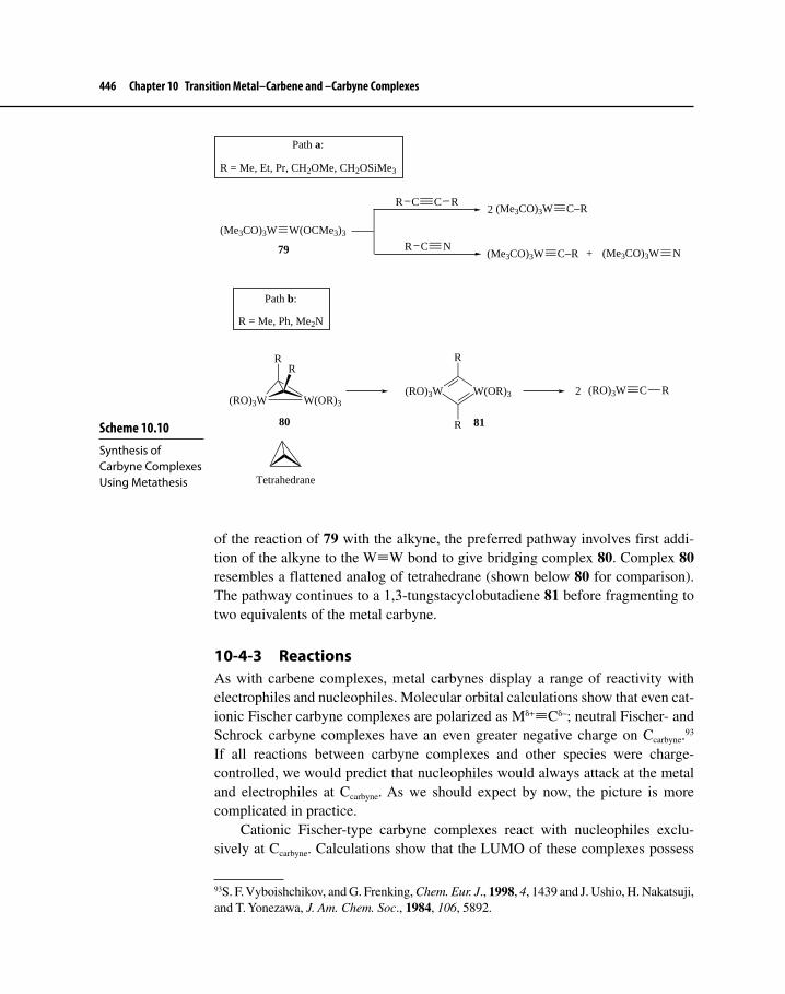
446 Chapter 10 Transition Metal–Carbene and –Carbyne Complexes
of the reaction of 79 with the alkyne, the preferred pathway involves first addi-tion of the alkyne to the W≡W bond to give bridging complex 80. Complex 80 resembles a flattened analog of tetrahedrane (shown below 80 for comparison). The pathway continues to a 1,3-tungstacyclobutadiene 81 before fragmenting to two equivalents of the metal carbyne.
10-4-3 ReactionsAs with carbene complexes, metal carbynes display a range of reactivity with electrophiles and nucleophiles. Molecular orbital calculations show that even cat-ionic Fischer carbyne complexes are polarized as Mδ+≡Cδ–; neutral Fischer- and Schrock carbyne complexes have an even greater negative charge on Ccarbyne.93 If all reactions between carbyne complexes and other species were charge- controlled, we would predict that nucleophiles would always attack at the metal and electrophiles at Ccarbyne. As we should expect by now, the picture is more complicated in practice.
Cationic Fischer-type carbyne complexes react with nucleophiles exclu-sively at Ccarbyne. Calculations show that the LUMO of these complexes possess
93S. F. Vyboishchikov, and G. Frenking, Chem. Eur. J., 1998, 4, 1439 and J. Ushio, H. Nakatsuji, and T. Yonezawa, J. Am. Chem. Soc., 1984, 106, 5892.
Scheme 10.10 Synthesis of Carbyne Complexes Using Metathesis
(Me3CO)3W W(OCMe3)3
79
Path a:
R = Me, Et, Pr, CH2OMe, CH2OSiMe3
Path b:
R = Me, Ph, Me2N
(RO)3W W(OR)3
RR
W(OR)3(RO)3W
R
R
(RO)3W C R2
80 81
Tetrahedrane
C C RR
C NR
(Me3CO)3W C−R
(Me3CO)3W C−R
2
+ (Me3CO)3W N

10-4 Metal–Carbyne Complexes 447
a large lobe centered about Ccarbyne and a much smaller lobe at the metal (Figure 10-12a). Instead of being controlled by charge density, such reactions are frontier orbital controlled. Equation 10.5494 shows an example of cationic Group 7 metal carbynes reacting with a variety of nucleophiles, a transformation that is also an excellent method for converting carbynes to carbenes.
Cp(CO)2M C PhNuc:
Cp(CO)2M C
Nuc
Ph
Nuc:− = F −, Cl−, Br−, I−; M = Mn, Re
10.54
Nucleophiles react differently with neutral Fischer carbyne complexes because now the LUMO and next higher unoccupied orbital (close to the LUMO in energy) of these complexes do not show a distinct region of electron deficiency at Ccarbyne. In addition to Ccarbyne, the metal and the ligands (such as the carbon of a CO ligand) offer sites suitable for nucleophilic attack (Figure 10-12b, which shows only the lobes on Ccarbyne and Cr). Equation 10.55 shows the attack of a phosphine or phosphite on the metal of neutral Group 6 carbynes.95
trans-Br(CO)4M C Ph + L mer-Br(CO)3(L)M C Ph + CO
L = PPh3, P(OPh)3; M = Cr, W
10.55
The reaction is first order in the presence of excess phosphine with a positive entropy of activation, suggesting that ligand substitution occurs via a dissociative pathway.
94E. O. Fischer, C. Jiabi, and S. Kurt, J. Organomet. Chem., 1983, 253, 231 and E. O. Fischer and J. Chen, Huaxue Xeubao, 1985, 43, 188.95M. H. Chisholm, K. Folting, D. M. Hoffman, and J. C. Huffman, J. Am. Chem. Soc., 1984, 106, 6794.
Figures 10-12a LUMO of a Cationic Fischer Carbyne Complex
Cr C HCO
[(CO)5Cr CH]+

448 Chapter 10 Transition Metal–Carbene and –Carbyne Complexes
Figure 10-12b LUMOs of a Neutral Fischer Carbyne Complex Showing Only the M−Ccarbyne Interactions
Cr C HCl Cr C HCl
LUMO LUMO + 1
Cl(CO)4Cr C−H
On the other hand, neutral Os alkylidyne 82 undergoes reaction with metha-nol to give carbene complex 83 (equation 10.56).96 It would appear that 82 under-goes reaction with nucleophilic methanol at Ccarbyne first, which is followed by proton transfer to Os. Such reactivity would be consistent with that associated with Fischer carbyne complexes, yet the metal center is more electron-rich than the group 6 metal complex reactant in equation 10.55.
Os(i-Pr)2P
Ph
82
MeOHOs
Ph
83
OMeH
(i-Pr)2P
10.56
Schrock carbynes and Group 8 (M = Os, Ru) alkylidynes react with electrophiles, typically at Ccarbyne. Equation 10.57 shows the electrophilic addi-tion of HCl across the M≡C of an Os carbyne complex in a manner reminiscent of Markovnikov addition of HCl across an unsymmetrical C≡C bond. The reac-tion presumably begins by attack of H+ at Ccarbyne, followed by ligand attachment of Cl–.97
COsC
C
PPh3
PPh3
MeO
O
HClOs
Ph3P
Ph3P
CCl
C H
Me
O
Cl:
Os
Ph3P
PPh3
CCl
C H
Me
O
Cl
+ CO
10.57
96See Footnote 89.97G. R. Clark, K. Marsden, W. R. Roper, and L. J. Wright, J. Am. Chem. Soc., 1980, 102, 6570.

Suggested Readings 449
Reaction of the Mo Schrock carbyne complex in equation 10.58 with HBF4 results in protonation at Ccarbyne, followed by rearrangement to the thermodynamically more stable Mo−H complex. The BF4
– ion is such a weakly coordinating ligand that substitution at the metal does not occur.98
Mo C(MeO)3P
(MeO)3P
Mo C(MeO)3P
(MeO)3P H
HBF4
−78 oC
BF4−
Mo C(MeO)3P
(MeO)3P H
BF4−
10.58
Other Lewis acids react with metal carbynes. Although the initial attack often occurs at Ccarbyne, the final product may be the result of subsequent reactions that may be difficult to rationalize mechanistically.99 Some of the problems at the end of Chapter 10 will depict more of the chemistry of carbyne complexes. Perhaps the most significant reaction of carbyne complexes is π bond metathesis, which has been alluded to in the discussion on procedures for metal–carbyne synthesis. We will see more consideration of this reaction in Chapter 11.
Suggested Readings
Metal Carbene Complex StructureG. Frenking, M. Solà, and S. F. Vyboishchikov, “Chemical Bonding in Transition Metal
Carbene Complexes,” J. Organomet. Chem., 2005, 690, 6178.T. Strassner, “Electronic Structure and Reactivity of Metal Carbenes,” Top. Organomet.
Chem., 2004, 13, 1.G. Frenking and N. Fröhlich, “Bonding in Transition–Metal Compounds,” Chem. Rev.,
2000, 100, 717.
Fischer Carbene ComplexesC. F. Bernasconi, “The Physical Organic Chemistry of Fischer Carbene Complexes,”
Adv. Phys. Org. Chem., 2002, 37, 137.K.-H. Dötz, H. Fischer, P. Hofmann, F. R. Kreissl, U. Schubert, and K. Weiss, Transition
Metal Carbene Complexes, Verlag Chemie: Weinheim, Germany, 1983.
98M. Bottrill, M. Green, A.G. Orpen, D. R. Saunders, and I. D. Williams, J. Chem. Soc., Dalton Trans., 1989, 511.99The synthesis and reactivity of metal carbynes has been comprehensively reviewed. See M. A. Gallop and W. R. Roper, Adv. Organomet. Chem., 1986, 25, 121; H. P. Kim and R. J. Angelici, Adv. Organomet. Chem., 1987, 27, 51; and A. Mayr and H. Hoffmeister, Adv. Organomet. Chem., 1991, 32, 227. More recent summaries of carbyne reactions appear annu-ally in the journal Coordination Chemistry Reviews; see, for example, G. Jia, Coord. Chem. Rev., 2007, 251, 2167, for a recent review of the chemistry of Os carbyne complexes.

450 Chapter 10 Transition Metal–Carbene and –Carbyne Complexes
F. J. Brown, “Stoichiometric Reactions of Transition Metal Carbene Complexes,” Prog. Inorg. Chem. 1980, 27, 1.
Schrock Carbene Complexes (Alkylidenes)R. R. Schrock, “High Oxidation State Multiple Metal–Carbon Bonds,” Chem. Rev.,
2002, 102, 145.R. C. Hartley and G. J. McKiernan, “Titanium Reagents for the Alkylidenation of
Carboxylic Acids and Carbonic Acid Derivatives,” J. Chem. Soc., Perkin Trans. 1, 2002, 2763.
N-Heterocyclic Carbene ComplexesF. E. Hahn and M. C. Jahnke, “Heterocyclic Carbenes: Synthesis and Coordination
Chemistry,” Angew. Chem. Int. Ed., 2008, 47, 3122.E. Peris, “Routes to N-Heterocyclic Carbene Complexes,” Top. Organomet. Chem.,
2007, 21, 83.F. Glorius, “N-Heterocyclic Carbenes in Catalysis—An Introduction,” Top. Organomet.
Chem., 2007, 21, 1.
CyclopropanationM. P. Doyle, M. A. McKervey, and T. Ye, Modern Catalytic Methods for Organic
Synthesis with Diazo Compounds, Wiley: New York, 1998.
Metal Carbyne ComplexesP. F. Engel and M. Pfeffer, “Carbon–Carbon and Carbon–Heteroatom Coupling
Reactions of Metallacarbynes,” Chem. Rev., 1995, 95, 2281.H. Fischer, P. Hofmann, F. R. Kreissl, R. R. Schrock, U. Schubert, and K. Weiss,
Carbyne Complexes, VCH Publishers: New York, 1988.H. P. Kim and R. J. Angelici, “Transition Metal Complexes with Terminal Carbyne
Ligands,” Adv. Organomet. Chem., 1987, 27, 51.See also the Schrock Chemical Review (2002) paper from above.
Problems10-1 Assuming that Fischer-type carbene complexes react similarly to ketones
and that phosphorus ylides are good carbon nucleophiles, predict the products in the following reaction:
(CO)5W=C(Ph)(Ph) + Ph3P=CH2 +
10-2 The chemistry outlined on the next page was used to produce a cyclic arene–chromium carbene complex.100
100C. A. Merlic, D. Xu, and S. I. Khan, Organometallics, 1992, 11, 412.

Problems 451
I 1) BuLi2) Cr(CO)6
3) MeOTf
OMe
Cr(CO)5 MeO
Cr
C
CO
O
∆
a. Describe in detail what happens in each reaction step.b. The carbene complex above is interesting because it was unreac-
tive toward nucleophiles under conditions that cause ordinary Fischer-type carbene complexes to react readily (for example, it did not undergo the chemistry shown in equations 10.27–10.29). X-ray analysis showed that the M−Ccarbene bond distance was 195.3 pm and the bond distance between the metal and carbonyl carbon (M−CO) was 184 pm. This contrasts with M−Ccarbene and M−CO bond distances of 200–210 pm and 180 pm, respectively, for Fischer carbene complexes such as (CO)5Cr=C(OCH3)(Ph). Explain why the cyclic arene–Cr carbene complex is not electrophilic in its chemical behavior.
10-3 A method for producing Group 10 metal–NHC complexes is the follow-ing. What kind of fundamental organometallic reaction is involved in each step with this method?101
N NMeMe
Cl
Cl−
Pd(PPh3)4Pd ClPh3P
PPh3
NNMeMe
Pd PPh3Ph3P
Cl
NNMeMe
Cl− Cl−
+ 2 PPh3
10-4 Propose a reasonable mechanism for the transformation shown below. Assume that the first step is protonation at Ccarbyne.
(t-BuO)3W C CH2CH3 + 2 RCO2H Wt-BuO
t-BuOO2CR
O2CR
CH3
+ t-BuOH
101D. Kremzow, G. Seidel, C. W. Lehmann, and A. Fürstner, Chem. Eur. J., 2005, 11, 1833.
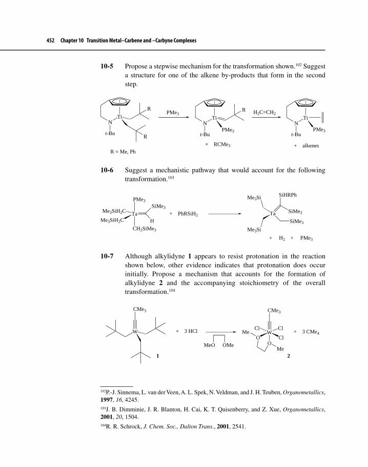
452 Chapter 10 Transition Metal–Carbene and –Carbyne Complexes
10-5 Propose a stepwise mechanism for the transformation shown.102 Suggest a structure for one of the alkene by-products that form in the second step.
TiN
R
Rt-Bu
PMe3Ti
NPMe3
R
t-Bu
+ RCMe3
H2C=CH2Ti
NPMe3
t-Bu
+ alkenesR = Me, Ph
10-6 Suggest a mechanistic pathway that would account for the following transformation.103
TaMe3SiH2C
Me3SiH2C
PMe3
CH2SiMe3
SiMe3
H+ PhRSiH2 Ta
SiHRPh
SiMe3
Me3Si
Me3Si
SiMe3
+ H2 + PMe3
10-7 Although alkylidyne 1 appears to resist protonation in the reaction shown below, other evidence indicates that protonation does occur initially. Propose a mechanism that accounts for the formation of alkylidyne 2 and the accompanying stoichiometry of the overall transformation.104
W
CMe3
+ 3 HCl WO
Cl Cl
ClO
CMe3
Me
Me + 3 CMe4
MeO OMe
1 2
102P.-J. Sinnema, L. van der Veen, A. L. Spek, N. Veldman, and J. H. Teuben, Organometallics, 1997, 16, 4245.103J. B. Dimminie, J. R. Blanton, H. Cai, K. T. Quisenberry, and Z. Xue, Organometallics, 2001, 20, 1504.104R. R. Schrock, J. Chem. Soc., Dalton Trans., 2001, 2541.

Problems 453
10-8 Predict the organic product that would result from the following reaction.105
TiPhMe/50 oC
+
O O
10-9 Consider the reaction shown in which I– replaces the trans Br– in complex 3. The rate law for this reaction was determined to be
rate = k[3][I–].
Kinetic parameters measured included ∆H‡ = 13.5 kcal/mol and ∆S‡ = −7.9 eu. The rate of reaction was insensitive to the leaving group, so when the relative rate of reaction (1,1,2-trichloroethane solvent) when Br– was the leaving group was compared with I– as the leaving group, k(Br)/k(I) = 1.2. What kind of fundamental organometallic reaction occurs here? Propose a mechanism for this reaction.106
trans-Br(CO)4Cr≡C−Ph + LiI trans-I(CO)4Cr≡C−Ph + LiBr 3
10-10 Propose a mechanism for the transformation shown.107
OsC
H
Ph(i-Pr)3P
Cl
CH3LiOsH
(i-Pr)3P
Ph
+ LiCl
10-11 Reaction of dihydrogen complex 4 with phenylethyne gives vinylidene 5 as shown. No other reagents are required for this reaction. Propose a pathway from 4 to 5. [Hint: The first step probably involves elimination of HCl.]108
105N. A. Petasis and E. I. Bzowej, Tetrahedron Lett., 1993, 34, 943.106H. Fischer and S. Friedrich, J. Organomet. Chem., 1984, 275, 83.107See Footnote 89.108M. L. Buil, O. Eisenstein, M. A. Esteruelas, C. García-Yebra, E. Gutiérrez-Puebla, M. Oliván, E. Oñate, N. Ruiz, and M. A. Tajada, Organometallics, 1999, 18, 4949.

454 Chapter 10 Transition Metal–Carbene and –Carbyne Complexes
OsCl
Cl
C
(i-Pr)3P
(i-Pr)3P
H
H
O
4
C CHPh
5
Os C
H
Ph
(i-Pr)3P
(i-Pr)3P
C
Cl
Cl
O
10-12 The reaction below follows a first-order rate law to form carbyne complex 6, and it is faster when X = Br than when X = Cl. When R is changed from methyl to isopropyl, the rate increases by a factor of 107. Although increases in rate occur when solvents become more polar, these rate enhancements are modest compared with solvent effects on reactions that generate intermediates with full-fledged charges. Adding more Cl– or increasing the pressure of CO has no effect on reaction rate. Finally, the addition of high concentrations of PPh3 does not affect reac-tion rate, but it does result in the formation of compound 7 (R = Et, X = Br). Spectral characteristics of 7 were as follows: IR: ν = 2043, 1980, 1950, and 1570 cm–1 (1575 cm–1 in the starting material when X = Br and R = Et); NMR: δ = 7.6 (multiplet, 15 H), 3.1 (quartet, 4 H), and 1.2 ppm (triplet, 6 H). The rate of reaction for treatment of 6 with PPh3 to form 7 is much faster than the rate of formation of 7 from the carbene complex starting material.109
a. Propose a structure for compound 7.b. Propose a stepwise mechanism for the formation of compound 6 and
for the formation of compound 7 from both the starting material and compound 6.
(CO)5Cr C
X
NR2
∆X(CO)4Cr C NR2 + CO
7
R = alkylX = Cl, Br
PPh3
+ CO
6
(C26H25BrNO3PCr)
109C. F. Bernasconi, Adv. Phys. Org. Chem., 2002, 37, 137.

Problems 455
10-13 Predict the structure of product (8) for the following dirhodium- catalyzed reaction.110
Rh2(OAc)48 + N2CHN2
OHAcO
OAc
Spectral characteristics of compound 8:
IR: ν = 1795 and 1751 cm–1
1H NMR: δ = 4.93 (singlet, 4H), 2.16 (singlet, 2H), and 2.02 ppm (singlet, 6 H)
110P. Dowd, P. Garner, R. Schappert, H. Irngartinger, and A. Goldman, J. Org. Chem., 1982, 47, 4240.
In Chapter 11 we will see how metal–carbene complexes are involved in a pro-cess known as metathesis, which we encountered briefly in Chapter 10. Metathesis is now used to synthesize everything from low-molecular-weight hydrocarbons to complex drugs to high-molecular-weight materials that are useful in everyday life. We will discover in Chapter 11 that these giant molecules result from polym-erization reactions, which are catalyzed not only by metal–carbene complexes but also by early- and late-transition metal compounds that are not metal carbenes.
11-1 π BOND METATHESISEquation 11.1 shows a formal interchange of substituent groups (typically alkyl groups or H) attached to the C=C bond of either the same or two different alkenes. Such a reaction is termed π bond metathesis, olefin1 metathesis, or simply metath-esis.2 Alkynes can also undergo these interchange reactions by a similar path-way; these transformations will be discussed in a subsequent section in Chapter 11. Another type of metathesis (equation 11.2), which involves reorganization ofsingle bonds, is called σ bond metathesis; we will discuss this reaction toward theend of Chapter 11.
1Olefin is an older, but still commonly-used term for alkene. The name derives from two Latin words—oleum (oil) and ficare (to make)—that were combined to describe the reaction of ethene (a gas) with Cl2 to give ClCH2−CH2Cl (a liquid or “oil”). Chemists, especially those employed in industrial settings, often use the word olefin interchangeably with alkene.2The word metathesis was coined from two Greek words: meta (change) and thesis (position).
Metathesis and Polymerization Reactions
ELEVEN
456

11-1 π Bond Metathesis 457
C
C
H R1
R2H
2
C C
C C
H
R1R1
H
H
R2R2
H+
C
C
H R1
R2H
+C
C
H R3
R4H
C C
C C
H
R3R1
H
H
R4R1
H+
+ E-isomers
C C
C C
H
R3R2
H
H
R4R2
H++ + E-isomers
11.1
LnM R
Y Z
+LnM
Y
R
Z
+
11.2
Discovered independently in the mid 1950s by workers at DuPont, Standard Oil of Indiana,3 and Phillips Petroleum,4 olefin metathesis is a reaction catalyzed, either homo- or heterogeneously, primarily by complexes of Ru, Mo, W, Re, and some Group 4 and 5 metals. The reaction often occurs under very mild conditions (room temperature and pressure). The original metathesis reactions involved the transformation of low-molecular-weight alkenes into other simple alkenes. Equation 11.3 shows conversion of propene to ethene and 2-butenes (known as the Triolefin Process) which was commercialized in 1966. Later the Triolefin Process was discontinued because ethylene and butenes became available less expensively from other processes.5 Today, chemical engineers take advantage of the reversibility of this and most other olefin metathesis reactions, and they run the Triolefin Process (now also known as Olefin Conversion Technology or OCT) such that the more economically valuable propene is produced from mixtures of ethene and 2-butenes.
+ H2C CH2LnM
+2
11.3
3E. F. Peters and B. L. Evering, US Patent 2,963,447, assigned to Standard Oil of Indiana, 1960.4R. L. Banks and G. C. Bailey, Ind. Eng. Chem. Prod. Res., 1964, 3, 170 (Phillips Petroleum).5For a summary of the history of the metathesis reaction written by two of its co-discoverers, see R. L. Banks, Chemtech, 1986, 16, 112 and H. Eleuterio, Chemtech, 1991, 21, 92 (DuPont).

458 Chapter 11 Metathesis and Polymerization Reactions
Equations 11.1 and 11.3 depict a type of metathesis known as cross- metathesis (CM). Several other types are known, and these are summarized in Scheme 11.1. Path a in Scheme 11.1 outlines ring-closing metathesis (RCM), which has become extremely useful in making rings of many different sizes. The reverse reaction (path b), known as ring-opening metathesis (ROM), is most useful when run under con-ditions that allow polymerization of the diene monomer to occur (path c). Under such conditions, we have a transformation called ring-opening metathesis polym-erization (ROMP). Path d shows a type of CM, but this time the starting material is a diene that can undergo polymerization under a process known as acyclic diene metathesis polymerization (ADMET). Later in Chapter 11 we shall encounter several examples and applications of these types of metathesis reactions.
Metathesis is now used in the production of specialty chemicals, agricultural chemicals, drugs, and polymers with unique properties, and interest in using it as a means to generate other new materials remains strong. The economic importance of olefin metathesis to the chemical industry has been a stimulus for research on the mechanism of this reaction. In addition to providing obvious monetary benefits, basic study on the metathesis reaction promoted a synergistic melding of the disciplines of catalysis and organometallic chemistry, the result of which was significant advance-ment of our knowledge of the chemical properties of metal carbene complexes and of understanding their role in alkene interchange and polymerization. Green benefits of metathesis reactions are high atom economy and mild reaction conditions. On an industrial scale, it is often possible to recycle by-products in subsequent metathesis exchange reactions so that the highest possible yields of desired products result.6
6C. L. Dwyer, “Metathesis of Olefins,” in Metal-Catalysis in Industrial Organic Processes, G. P. Chiusoli and P. M. Maitlis, Eds., Royal Society of Chemistry: Colchester, UK, 2006, pp. 201–217.
Scheme 11.1 Major Types of Olefin Metathesis Reactions
CnCn
a Ring-closing metathesis (RCM)
bRing-opening metathesis (ROM)
+
Cn
mCat.
Cn
Cat
Cn Cn
CR2
m−2
E or Z stereochemistry results
Cnm
Cat. Cn
CnCnm−2
: No stereochemistry specified
c
d
Ring-opening metathesispolymerization (ROMP)
Acyclic diene metathesispolymerization (ADMET)
+ m−2

11-1 π Bond Metathesis 459
In 2005, Yves Chauvin, Robert Grubbs, and Richard Schrock were awarded the Nobel Prize in Chemistry for their fundamental studies on the mechanism and applications of metathesis. We will encounter much of their work in the following sections.
11-1-1 The Mechanism of π Bond MetathesisEquation 11.1 shows only two possibilities for exchange of alkyl substituents during CM. Several other product combinations are possible and, given enough time for the reaction to reach equilibrium, all possible products form in amounts based upon their relative free energies (see equation 11.4 below and Exercise 11-1 for examples). The reaction may be manipulated to achieve desired product combinations, however. For example, a self-metathesis of a terminal alkene will produce ethene as one of the products. The reaction may be driven toward forma-tion of ethene and an internal alkene by collecting volatile ethene as it forms. The presence of high concentrations of ethene during metathesis, on the other hand, converts an internal alkene to a terminal one.
+LnM
+ + +
Elucidation of the mechanism of metathesis, as with any mechanistic pathway, requires knowing which bonds are broken and which are formed. Over the years, investigators of this mechanism have considered several pathways, three of which are:7
1. Mechanism 1: Transfer of alkyl groups from one C=C bond to another as shown in equation 11.5.8
7See also R. Grubbs and T. K. Brunck, J. Am. Chem. Soc., 1972, 94, 2538 and C. G. Biefield, H. A. Eick, and R. H. Grubbs, Inorg. Chem., 1973, 12, 2166, for an alternative proposal for involvement of a metallocyclopentane as an intermediate in CM.8N. Calderon, H. Y. Chen, and K. W. Scott, Tetrahedron Lett., 1967, 3327. Calderon was the first to coin the term olefin metathesis for the olefin exchange reaction that is typified by the Triolefin Process.
Assume 2-pentene and 2-hexene undergo metathesis. At equilibrium, what are all the possible alkenes that could be present, neglecting stereochemistry about the double bond? Remember to consider self-metathesis reactions.
Exercise 11-1
11.4

460 Chapter 11 Metathesis and Polymerization Reactions
R CH CH R
R' CH CH R'
+
R CH CH R'
R' CH CH R
+LnM
(Only one exchange possibility shown)
Mechanism 1:
11.5
2. Mechanism 2: A pairwise breakage of C=C bonds followed by the con-struction of new C=C bonds, pictured in equation 11.6.9
LnM
R CH CH R
R' CH CH R'
LnMR' R'
RRR
CH
CH
R'
R
CH
CH
R'
LnM
1
Mechanism 2:
11.6
3. Mechanism 3: A non-pairwise breakage of C=C bonds followed by formation of new C=C bonds outlined in Scheme 11.2.
A single experiment (Scheme 11.3), involving self metathesis of a symmetri-cal alkene, clearly indicated that Mechanism 1 could not occur.10 A mechanism involving alkyl group transfer by C−C bond cleavage should give several differ-ent labeled 2-butene isomers, whereas cleavage of the C=C bond would give only one structure (neglecting stereoisomers). Because the only product isolated upon equilibrium contained four deuterium atoms (d4-2-butene), the results are consis-tent with cleavage of the double bond (Mechanisms 2 or 3).
The study of organic chemistry, however, tells us that C=C bonds are rather strong (145–150 kcal/mol), and yet metathesis, remarkably, is a reaction capable of breaking these bonds and forming new ones under rather mild conditions. The question remains: how do C=C bonds break and then reform?
In 1967, Bradshaw11 proposed (equation 11.6) that metathesis occurs first by coordination of the two alkenes to the metal followed by cycloaddition of
9C. P. C. Bradshaw, E. J. Howman, and L. Turner, J. Catal. 1967, 7, 269.10N. Calderon, E. A. Ofstead, J. P. Ward, W. A. Judy, and K. W. Scott, J. Am. Chem. Soc., 1968, 90, 4133.11See Footnote 9.
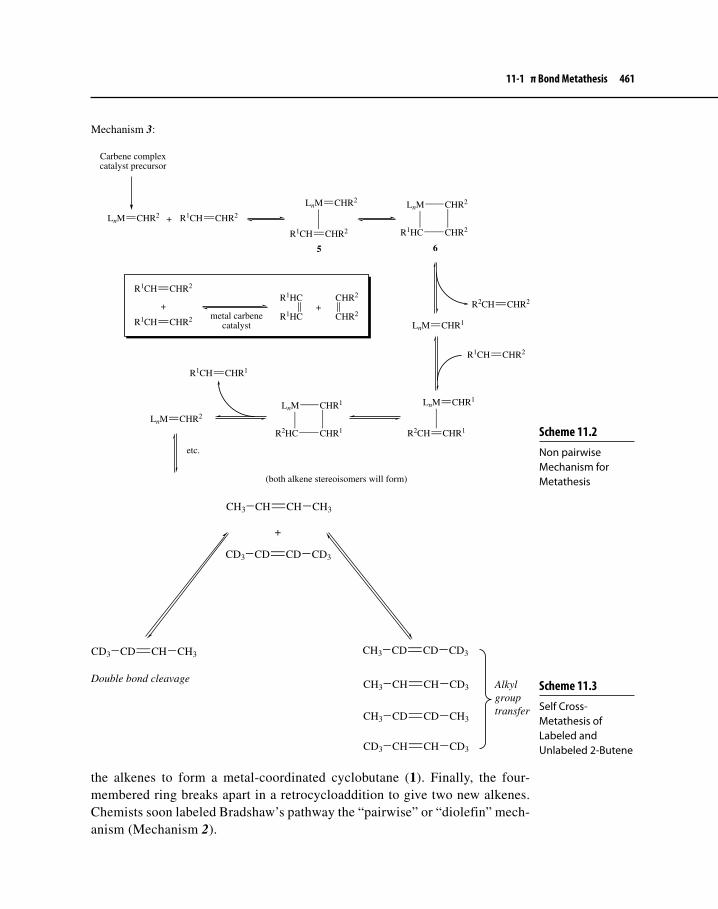
11-1 π Bond Metathesis 461
Scheme 11.2 Non pairwise Mechanism for Metathesis
LnM CHR2 R1CH CHR2
LnM CHR2
R1CH CHR2
+
LnM
R1HC CHR2
CHR2
5 6
Mechanism 3:
Carbene complexcatalyst precursor
LnM CHR1
R2CH CHR2
R1CH CHR2
LnM CHR1
R2CH CHR1
LnM
R2HC CHR1
CHR1
R1CH CHR1
LnM CHR2
etc.
(both alkene stereoisomers will form)
R1CH CHR2
R1CH CHR2
+R1HC
R1HC+
CHR2
CHR2metal carbenecatalyst
Scheme 11.3 Self Cross-Metathesis of Labeled and Unlabeled 2-Butene
CH3 CH CH CH3
CD3 CD CD CD3
CD3 CD CH CH3 CH3 CD CD CD3
CH3 CH CH CD3
CH3 CD CD CH3
CD3 CH CH CD3
+
Alkylgrouptransfer
Double bond cleavage
the alkenes to form a metal-coordinated cyclobutane (1). Finally, the four-membered ring breaks apart in a retrocycloaddition to give two new alkenes. Chemists soon labeled Bradshaw’s pathway the “pairwise” or “diolefin” mech-anism (Mechanism 2).

462 Chapter 11 Metathesis and Polymerization Reactions
In 1971, Hérisson and Chauvin12 performed an experiment described in equation 11.7. They isolated three major products, 2 (C10), 3 (C9), and 4 (C11), upon tungsten-catalyzed CM of cyclopentene and 2-pentene. Product 2 is expected as the direct result of pairwise metathesis of the two starting materials; the other two products could result from subsequent reactions of 2 with 2-pentene. At equi-librium, all products would be present in nearly statistical distribution accord-ing to the pairwise mechanism. What troubled Hérisson and Chauvin, however, was the observation that, upon quenching the reaction well before equilibrium could be achieved, a statistical distribution of the three products was already present.
Me
Et
+
Me
Et
Me
Me
Et
Et
+ +
432
2 1 1: :
11.7
Mechanism 3 shows a pathway that was strongly influenced by the results of Hérisson and Chauvin and is outlined in Scheme 11.2. Two key intermediates in this pathway are an alkene–metal carbene complex (5) and a metallacyclobu-tane (6), formed through concerted cycloaddition of the M=C and C=C bonds. A highly significant feature of the mechanism, caused by the unsymmetrical struc-ture of 6, is its explanation of randomization early in the course of reaction. The Hérisson–Chauvin mechanism does not require a specific pair of alkenes to interact directly for metathesis to occur, hence the name “non-pairwise” mechanism.
12J. L. Hérisson and Y. Chauvin, Makromol. Chem., 1971, 141, 161. This paper does not propose the discrete intermediates, 5 and 6, but it does suggest that carbene complexes could interact with alkenes separately in a non-pairwise manner such that a new alkene and a new carbene complex could form after a bond reorganization. The mechanism shown in Scheme 11.2 is the non-pairwise mechanism that was elucidated after much work by other chemists, and it is discussed later in this section and in Section 11-1-2.
Exercise 11-2 Show how 3 and 4 (equation 11.7) could form using the pairwise mecha-nism for metathesis.

11-1 π Bond Metathesis 463
The early development of Mechanism 3 was bold for its day because Fischer carbene complexes had just been discovered a few years earlier, and alkylidenes were not yet known. The carbene complexes prepared before 1971 also did not catalyze olefin metathesis. With the discovery of Schrock carbene complexes and the demonstration that some alkylidenes could promote metathesis, the non- pairwise mechanism became more plausible (Section 11-1-2). It was, however, the elegant work of Katz and co-workers that provided early substantial support for the Hérisson–Chauvin mechanism.
First, Katz13 conducted an experiment similar to that of Hérisson and Chauvin (equation 11.8), which he termed the “double cross” metathesis. If Mechanism 2 were operative, the product ratios [8]/[7] and [8]/[9] should be zero when concen-trations were extrapolated back to the very beginning of the reaction (t0), because 8—the double cross product—would have to form after the symmetrical products 7 and 9.
CH3CH=CHCH3
(C4)
CH3(CH2)2CH=CH(CH2)2CH3
+
(C8)
+
Me
Me7 (C12)
Pr
Pr9 (C16)
+
Me
Pr8 (C14)
+
+ Me−CH=CH−Pr
+ Other products
Mo-Alcat.
11.8
The non-pairwise mechanism (Mechanism 3) should provide some of the unsym-metrical 8 quickly, thus making the ratios [8]/[7] and [8]/[9] non-zero at t0. When the experiment was run, Katz found values of [8]/[7] = 0.40 and [8]/[9] = 11.1 at t0.
Despite this strong evidence supporting the non-pairwise mechanism, others objected that the pairwise mechanism could explain the results of Katz’s experi-ment if another step in the pairwise mechanism were rate determining. Consider Scheme 11.4, in which initial “single cross” metathesis is rapid to form the C12 alkene (7). If 7 sticks to the metal and 4-octene attacks in a rate-determining step
13T. J. Katz and J. McGinness, J. Am. Chem. Soc., 1975, 97, 1592, and 1977, 99, 1903.
Starting with LnM=CH−Me or LnM=CH−Et, cyclopentene, and 2-pentene, show how the non pairwise mechanism could account for initial formation of 3 and 4 as well as 2 (equation 11.7).
Exercise 11-3

464 Chapter 11 Metathesis and Polymerization Reactions
Scheme 11.4 “Sticky Olefin” Hypothesis
+ MLn
MLn
MLn
MLn
MLn
MLn
7 (C12) 8 (C14)
7-M
10
LnM
fasta
b bslow slow
fast fast
fastfast

11-1 π Bond Metathesis 465
(step b) to displace one of the alkene groups to give 10, then metathesis would give double cross product 8. If 7 sticks to the metal long enough, several displace-ments and subsequent metatheses could occur, providing a statistical distribution of products even at the beginning of the reaction. If, on the other hand, pairwise metathesis (step a) is rate determining, even this modified pairwise mechanism fails to explain the results of Katz and the earlier results of Hérisson and Chauvin, because the rate-determining step would produce only the single cross-product. The proposition that an alkene could stick to the metal and subsequently be dis-placed by another alkene was called the “sticky olefin” hypothesis, and it consti-tutes a modification of Mechanism 2.14
At this point, the non-pairwise (Mechanism 3) and sticky olefin-modified pairwise process (Mechanism 2) both could explain the double cross experiment. More definitive proof was required, and this was provided independently by Grubbs and Katz through some clever experiments. In one experiment,15 metath-esis of a 1:1 mixture of dialkene 11 and deuterated partner 12 gives cyclohexene and three ethenes with different amounts of deuterium incorporation (equation 11.9). The design of the experiment was astute in at least two respects. First, cyclohexene, although a simple disubstituted alkene, is a notable exception to the rule that sterically unhindered alkenes undergo metathesis; in this case, it does not react with starting material or other products in the presence of the W-catalyst. Second, the ethenes are sufficiently volatile that they could be removed and col-lected as formed, thus preventing their reaction with starting material. Because of these constraints, the initial products observed would truly be those formed dur-ing the first metathesis. For example, secondary reactions that could occur via the sticky olefin-modified pairwise pathway (Mechanism 2) and lead to scrambled products would not take place at the initial stages of the reaction. A non-pairwise mechanism predicts that the ratio of d0:d2:d4-ethenes should be 1:2:1, whereas the sticky-olefin-metathesis mechanism does not; experiment showed results close to the 1:2:1 ratio.
CH2
CH2
+
CD2
CD2
+
H2C=CH2
+
H2C=CD2
+
D2C=CD2
PhWCl3-AlCl3
11 12
11.9
14N. Calderon, Acc. Chem. Res., 1972, 5, 127.15R. H. Grubbs, P. L. Burk, and D. D. Carr, J. Am. Chem. Soc., 1975, 97, 3265.

466 Chapter 11 Metathesis and Polymerization Reactions
Addition of excess d0-ethene to the reaction mixture did not affect the ethene-d2/d4 product ratio, which means that the ethene products do not react with each other once formed. Moreover, mass spectral analysis of 11 and 12 both before the reaction started and after a short reaction time showed no scrambling of label between the two starting materials. This suggests that 11 and 12 must interact separately with the metal catalyst during metathesis and do not inter-act with each other before metathesis. Mechanism 3 best explains all of these results.
Equation 11.10 describes another experiment, performed by Katz, which is similar to Grubbs’ earlier work.16 A 1:1 ratio of d0- and d4-divinylbiphenyls gave a 1:2:1 ratio of ethenes as above. Again, the products are such that secondary metatheses do not occur.
CH2
CH2
+
CD2
CD2
+
H2C=CH2
+
H2C=CD2
+
D2C=CD2
Mo or Wcatalyst
Mo or W catalyst: M(NO)2Cl2[P(octyl)3]2/Al2Me3Cl3
11.10
Since the definitive experiments of Katz and Grubbs appeared in the literature, the non-pairwise mechanism has become the accepted pathway for metathesis. Subsequent investigations have supported this pathway.17,18 Key inter-mediates in the non-pairwise mechanism are metal–carbene and metallacyclo-butane complexes. Both have been prepared and shown to catalyze metathesis, and more recently both species have actually been observed in the same reaction mixture and shown to interconvert during it, thus offering additional support for Mechanism 3.19 The next section will cover the discovery of discrete metal-carbene complexes that do serve as metathesis catalysts.
16T. J. Katz and R. Rothchild, J. Am. Chem. Soc., 1976, 98, 2519.17For general reviews covering the mechanism of metathesis, see R. H. Grubbs, Prog. Inorg. Chem., 1978, 24, 1; T. J. Katz, Adv. Organomet. Chem., 1977, 16, 283; and R. H. Grubbs, “Alkene and Alkyne Metathesis Reactions,” in Comprehensive Organometallic Chemistry, G. Wilkinson, Ed., Pergamon Press: New York, 1982, Vol. 8, pp. 499–551.18For more modern reviews on the development of the mechanism of metathesis, see the following: A. M. Rouhi, Chem. Eng. News, 2002, 80, 34; D. Astruc, New J. Chem, 2005, 29, 42; T. J. Katz, New J. Chem., 2006, 30, 1844; D. Astruc, New J. Chem., 2006, 30, 1848; and C. P. Casey, J. Chem. Ed., 2006, 83, 192.19J. Kress, J. A. Osborn, R. M. E. Greene, K. J. Ivin, and J. J. Rooney, J. Am. Chem. Soc., 1987, 109, 899.

11-1 π Bond Metathesis 467
11-1-2 Metathesis CatalystsMetathesis catalysts may be either homo- or heterogeneous. Although complexes of Ru, Mo, and W seem to show the most activity, metathesis may be catalyzed in some instances by Ti and Ta species. Heterogeneous substances, such as WO3/silica or MoO3 and Mo(CO)6 supported on alumina, catalyze the Triolefin Process and others performed on an industrial scale. Mechanistic studies of the type described in the previous section were essentially impossible to do with heterogeneous catalysts because the nature of these catalysts was so ill defined. Further discussion of the mechanism of metathesis under heterogeneous catalysis is beyond the scope of this textbook.
The work on elucidating the mechanism of metathesis that occurred dur-ing the 1970s involved use of homogeneous catalysts, but even these were often mixtures of compounds, such as WCl6/AlEt2Cl or WCl6/BuLi. Even today, it is not clear how these mixtures, let alone heterogeneous catalysts, react to form the meta–carbene and metallacyclobutane intermediates that are now accepted as part of the mechanism of metathesis. Chauvin and Hérisson never observed carbene complexes or metallacyclobutanes in their seminal research, so it was not until later that other workers determined that these species were indeed interme-diates in the metathesis reaction and that carbene complexes did, in fact, catalyze metathesis.
The first definitive work that showed that a metal–carbene complex could promote metathesis was that of Casey and Burkhardt.20 They synthesized diphenyl tungsten–carbene complex 13 and demonstrated that the stoichiometric exchange process in equation 11.11 occurred.
(CO)5W
Ph
Ph
+
OMe
Ph
(CO)5W
OMe
Ph
+
Ph
Ph13
11.11
20C. P. Casey and T. J. Burkhardt, J. Am. Chem. Soc., 1974, 96, 7808.
Based upon your knowledge of alkene metathesis, what is the mechanism of the following transformation?
Ph C C HMoO3/SiO2
500 oCPh C C Ph H C C H+
Exercise 11-4

468 Chapter 11 Metathesis and Polymerization Reactions
Casey and Burkhardt reasoned that the metathesis mechanism influenced by Chauvin and Hérisson’s work was sufficient to explain their results. Complex 13 is interesting in that the pentacarbonyl substitution makes it similar to a traditional Fischer carbene complex, yet it also possesses Schrock character because both substituents at Ccarbene are hydrocarbon fragments.
In a series of papers that appeared in the mid to late 1970s, Katz and co-workers showed that complex 13 could catalyze metathesis reactions,21 not only CM reactions but also ROMPs of small-ring cycloalkenes.22 Although 13 was not a highly active catalyst, its use clearly demonstrated that metal–carbene complexes could be the true catalytically active species.
Up to this time, because complex 13 was not a highly active catalyst, there was concern that it may not be the true catalytic species in Katz’s CM and ROMP experiments. It was suspected that 13 could first transform to a carbene complex with W in a high oxidation state before metathesis occurred. Further advancement in the field occurred a few years later, with Schrock’s report in 1980 of alkylidenes 14 (M = Nb and Ta), which were active catalysts that led to productive metathesis.23 It was Schrock’s opinion that true metathesis catalysts consisted of alkylidenes with metals in high oxidation states and that the discov-ery of complex 14 was significant because it was the first carbene complex to catalyze productive metathesis. To this day, there is disagreement about who can claim to have first discovered a metal–carbene complex that was a true metathesis catalyst.24
(t-BuO)2(PMe3)(Cl)M C
14
Me = Nb, Ta
H
21See Footnote 13.22(a) T. J. Katz, S. J. Lee, and N. Acton, Tetrahedron Lett., 1976, 4247; (b) T. J. Katz and N. Acton, Tetrahedron Lett., 1976, 4251; and (c) T. J. Katz, S. J. Lee, and M. A. Shippey, J. Mol. Catal., 1980, 8, 219.23R. Schrock, S. Rocklage, J. Wengrovius, G. Rupprecht, and J. Fellmann, J. Mol. Catal., 1980, 8, 73 and S. M. Rocklage, J. D. Fellmann, G. A. Rupprecht, L. W. Messerle, and R. R. Schrock, J. Am. Chem. Soc., 1981, 103, 1440.24See Footnote 18.

11-1 π Bond Metathesis 469
Schrock’s group also looked into tungsten catalysts, such as compound 15. Although 15 also catalyzed metathesis, it required the presence of a Lewis acid such as AlCl3 to be effective.25
WCl
ClPEt3
PEt3CHCMe3
O
15
Continued work by Schrock’s group led to some very active catalysts. By replacing the oxo group of 15 with an imido ligand (to enhance steric hindrance), changing the metal to Mo, and replacing some ligands with finely-tuned alkoxy groups (containing fluorinated alkyl fragments to modify the electronic nature of these groups), Schrock was able to construct alkylidene 16 and numerous other structurally-related complexes, some of the most active catalysts for all types of metathesis detailed in Scheme 11.1.26
Mo
N
O
O
CF3F3CCH3
F3C
F3CH3C
CMe2Ph
H
16
25J. H. Wengrovius, R. R. Schrock, M. R. Churchill, J. R. Missert, and W. J. Youngs, J. Am. Chem. Soc., 1980, 102, 4515.26J. H. Oskam, H. H. Fox, K. B. Yap, D. H. McConville, R. O’Dell, B. J. Lichtenstein, and R. R. Schrock, J. Orgmetal. Chem., 1993, 459, 185.

470 Chapter 11 Metathesis and Polymerization Reactions
A chiral version of 16 (alkylidene 17), containing a biphenyldiolate ligand, is effective in producing metathesis products that exhibit high yields and excellent % ee values under mild conditions (equation 11.12).27
O
Mo
N
OO
MeMe
CMe2Ph
H
17
O O
O
CH3
CMe3
Me
Me
Me
MeCMe3
H
H
98% ee and 84% yield
< 25 oC
11.12
Parallel to Schrock’s efforts were those of Grubbs and co-workers.28 They studied Tebbe’s reagent and found that titanacyclobutanes derived from the reagent could be isolated. For example, they found that titanacycle 18 was in direct equilibrium with metal carbene 19 (equation 11.13). This system was not an active metathesis catalyst, but the work showed that both intermediates were important in the metathesis pathway. Further work found that reaction of Tebbe’s reagent with norbornene resulted in metallacycle 20, which promoted ROMP of additional equivalents of norbornene and produced a polymer that was relatively monodisperse29 (equation 11.14).30
27G. S. Weatherhead, J. G. Ford, E. J. Alexanian, R. R. Schrock, and A. H. Hoveyda, J. Am. Chem. Soc., 2000, 122, 1828.28For a nice summary of metathesis catalysis development from the Grubbs research group, see R. H. Grubbs, Tetrahedron, 2004, 60, 7117.29Polymers are often characterized by their polydispersity index (PDI), which is determined by dividing the weight average molecular weight (Mw) of a polymer sample by its number average molecular weight (Mn). The value of the PDI is ≥ 1, and large values of the PDI correspond to a polymer sample containing highly variable chain lengths for the individual polymer strands. A polymer is said to be relatively monodisperse when its PDI approaches the value of unity, indicating that all chain lengths are about the same. The mechanical prop-erties of a polydisperse polymer may be quite different from the same polymer whose MDI approaches unity.30L. R. Gilliom and R. H. Grubbs, J. Am. Chem. Soc., 1986, 108, 733.

11-1 π Bond Metathesis 471
Ti
Cp
Cp
Me
Me
Ti CH2
Cp
Cp
Me
Me
+
18 19
AlMe2
ClTi
Cp
Cp
Me
Me
AlClMe2
11.13
AlMe2
ClTi
Cp
Cp
Cp2Ti
Cp2Ti
etc. n
20
11.14
Although the Ti complexes served to help elucidate the true nature of metathesis catalysts, they were not useful in a practical sense because they were not as active as other catalysts and the oxophilic nature of Ti prevented their use in metathesis of alkenes containing oxygen groups.
It was Grubbs’ work with ruthenium, however, that led to numerous metathesis catalysts that are especially useful in the field of organic synthe-sis. Grubbs showed that ROMP of 7-oxanorbornene (21) amazingly could occur using a RuCl3 catalyst in H2O,31 and this work led to the development of Ru–alkylidene catalysts, the first of which was complex 22.32 Further mod-ification produced alkylidene 23,33 which is now called the first-generation Grubbs’ catalyst. A more active form of 23 is complex 24,34 which has an NHC (Section 10-1-1) as one of its ligands and is known as a second-generation cat-alyst. Organic chemists have made extensive use of the last two catalysts for CM and RCM reactions.
31B. M. Novak and R. H. Grubbs, J. Am. Chem. Soc., 1988, 110, 960.32S. T. Nguyen, L. K. Johnson, R. H. Grubbs, and J. W. Ziller, J. Am. Chem. Soc., 1992, 114, 3974 and S. T. Nguyen, R. H. Grubbs, and J. W. Ziller, 1993, 115, 9858.33P. Schwab, R. H. Grubbs, and J. W. Ziller, J. Am. Chem. Soc., 1996, 118, 100.34M. Scholl, T. M. Trnka, J. P. Morgan, and R. H. Grubbs, Tetrahedron Lett., 1999, 40, 2247.

472 Chapter 11 Metathesis and Polymerization Reactions
O
21
CRuCl
Cl
PCy3
PCy3Ph
Ph
22
H
CRuCl
Cl
PCy3
PCy3
Ph
H
23
CRuCl
Cl
PCy3
Ph
H
NNMeMe
MeMe
MeMe
24
It is interesting that the Ru alkylidenes that Grubbs discovered are both alkylidenes and complexes with the metal in a relatively low oxidation state (+2).35 As Grubbs has mentioned in his writings and conversations, there is a whole spectrum of reactivity in metal–carbene complexes, and it is difficult to classify the reactivity of many of these as being either Fischer type or Schrock type.36
The mechanism of Ru–alkylidene-catalyzed reactions has been investigated. Note that Grubbs’ first- and second-generation catalysts are 16-electron species, so if the first step involves complexation of an alkene to the metal, this process could occur in an associative or dissociative manner. Evidence suggests (see Scheme 11.5) that this occurs in a dissociative manner, however, first forming a 14-electron intermediate 25 and then 26a or 26b after complexation of the alkene. Gas-phase mass spectral evidence supports the initial formation of 25. Complexes similar to 26a and b have been isolated from reaction mixtures under appropriate conditions, but ruthenacyclobutane 27 has not been directly observed until quite recently.37
35It can be argued that, if one considers Grubbs catalysts to be true alkylidenes (Schrock carbene complexes), the oxidation state of Ru is +4.36R. H. Grubbs, T. M. Trnka, and M. S. Sanford, “Transition Metal–Carbene Complexes in Olefin Metathesis,” in Fundamentals of Molecular Catalysis, H. Kurosawa and A. Yamamoto, Eds., Elsevier: Amsterdam, 2003, pp. 187–193.37A recent NMR study characterized a ruthenacyclobutane anolog related to structure 27 starting with the methylidene analog of Grubbs’ second-generation catalyst. See E. F. van der Eide, P. E. Romero, and W. E. Piers, J. Am. Chem. Soc., 2008, 130, 4484.

11-1 π Bond Metathesis 473
There was speculation that this species existed as a transition state rather than a discrete intermediate.38
RCM and cross metathesis, using both Grubbs Ru–alkylidenes and Schrock’s Mo-catalysts, are routinely used in both academic and industrial research labo-ratories to produce complex organic molecules.39 These reactions constitute one of the greatest advances in synthetic methodology to occur in the past 15 years, and they play a significant role in the synthesis of molecules that exhibit phar-maceutical activity. Although the Schrock catalysts are often more active than the Grubbs variety, the latter complexes are more tolerant of different functional groups already in place on substrates and are easier to use. For example, Schrock catalysts typically must be used in glove boxes or manipulated on Schlenk lines, and Grubbs catalysts may be employed under standard conditions for running organic reactions.
11-1-3 Industrial Uses for Metathesis: Small MoleculesBesides the Triolefin Process or OCT, metathesis is a key step in a number of other industrial transformations used to produce small molecules. By far the most important application of metathesis for this task is connected with the Shell
38For a discussion of mechanistic studies of Ru–alkylidene catalysis of metathesis, see M. S. Sanford and J. A. Love, “Mechanism of Ruthenium-Catalyzed Olefin Metathesis Reactions,” in Handbook of Metathesis, Vol. 1, R. H. Grubbs, Ed., Wiley–VCH: Weinheim, Germany, 2003, pp. 112–131.39For a comprehensive review on the use of metathesis for the synthesis of complex organic molecules, see J. A. Love, “Olefin Metathesis Strategies in the Synthesis of Biologically Relevant Molecules,” in Handbook of Metathesis, Vol. 2, R. H. Grubbs, Ed., Wiley–VCH: Weinheim, Germany, 2003, pp. 296–360.
Scheme 11.5 Mechanism of Catalysis for Ru–Alkylidene Complexes
RuCl
Cl
PCy3
PCy3
R
HRu
Cl
Cl
PCy3
R
H
PCy3
+
RuCl
Cl
PCy3
R
H
R
R
RuCl
Cl
PCy3
R
H
RuCl
Cl
Cy3P R
R25
26a
26b
27

474 Chapter 11 Metathesis and Polymerization Reactions
Higher Olefin Process (SHOP), which was developed over 30 years ago by the Shell Oil Company and produces about a million tons per year of linear C12–C15 alcohols derived from C11–C14 alkenes.40 Most of these alcohols are subsequently converted into detergents and plasticizers.
Scheme 11.6 diagrams this process, which begins with a Ni-catalyzed41 oligomerization42 to give alkenes of various chain lengths. These are distilled into three different fractions corresponding to short-, medium-, and long-chain alkenes. The medium chains are used in the later stages of the process, but the short- and long-chain olefins are isomerized from terminal to internal alkenes. These then undergo metathesis over a heterogeneous catalyst of MoO3/Al2O3 or one that is Re-based. The resulting medium-weight alkenes (combined with a medium-length fraction from above) finally undergo hydroformylation, using a phosphine-modified Co catalyst, for which Shell is renowned (see Section 9-2-2). The catalyst promotes isomerization of internal double bonds to terminal before hydroformylation and subsequent hydrogenation occur.
A metathesis similar to OCT came on stream about the same time as the SHOP process. Ethenolysis43 of a mixture of 2,4,4-trimethyl-2-pentene and 2,4,4-trimethyl-1-pentene yields 3,3-dimethyl-1-butene (commonly called neohexene) plus isobutylene (equation 11.15).
+H2C=CH2
MoO3/SiO2/MgO
MoO3/SiO2/MgO
11.15
40A. J. Berger, U.S. Patent 3,726,938, 1973; P. A. Verbrugge and G. J. Heiszwolf, U.S. Patent, 3,776,975, 1973; E. R. Freitas and C. R. Gum, Chem. Eng. Progr., 1979, 75, 73; W. Keim, F. H. Kowaldt, R. Goddard, and C. Krüger, Angew. Chem. Int. Ed. Eng., 1978, 17, 466; and B. Reuben and H. Wittcoff, J. Chem. Ed., 1988, 65, 605.41For a discussion of the nature of the Ni oligomerization catalyst, see W. Keim, Angew. Chem., 1990, 102, 251.42Oligomers are low-molecular-weight polymers. They are analogous to peptides in the realm of biochemistry whereas proteins would be analogous to high-molecular-weight polymers.43Ethenolysis refers to methathesis involving ethene as one of the reactants. Such a reaction will liberate two terminal alkenes from the non-ethenylinic metathesis partner.

11-1 π Bond Metathesis 475
The process is quite atom economical because the isobutylene is recycled to undergo dimerization to the starting mixture of trimethylpentene isomers, and the metathesis catalyst, typically a mixture of WO3/silica and MgO, also promotes isomerization of the 1-pentene to the desired 2-isomer.44
This process, now run by the Chevron Phillips Chemical Company, produces over a million pounds of neohexene annually. Neohexene is a raw material used
44R. L. Banks, D. S. Banasiak, P. S. Hudson, and J. R. Norell, J. Mol. Catal., 1982, 15, 73.
Scheme 11.6 The Shell Higher Olefin Process (SHOP)
H2C=CH2"Ni-H" catalyst
CH3(CH2)2-5 CH CH2
CH3(CH2)11-16 CH CH2
+ CH3(CH2)6-10 CH CH2+
+(C18)
(C7)
MoO3/Al2O3CM
+
(C13)(C12)
Separated bydistillation
CH3(CH2)8-12 CH2OH
IsomerizationHydroformylationHydrogenation
Isomerization
For example:
Ni-H:
O
Ni−H
PPhPh
(mainly linear alcohols)

476 Chapter 11 Metathesis and Polymerization Reactions
for production of synthetic perfume ingredients (called musks) and Terbinafine, an antifungal pharmaceutical that is also called Lamisil (28).45
N
Me
28
Pheromones are chemicals that are used by animals and plants for commu-nication. Insects utilize pheromones extensively to indicate their availability for reproduction, to sound alarms, and to make known the presence of food. The use of pheromones in small amounts in traps can interfere with the reproduc-tion of harmful insects in an environmentally friendly manner. Recently, Grubbs’ second-generation catalyst (24) was used to synthesize on an industrial scale the sex attractant pheromone of the peach twig borer, a pest that attacks peach, plum, nectarine, and almond crops.46 Equation 11.16 shows how Ru-catalyzed metath-esis of 5-decene and 1,10-diacetoxy-5-decene produces a 50% yield of E–Z mixture (the desired E-isomer predominates, and the presence of small amounts of Z-isomer does not lower the activity of the pheromone) of the desired phero-mone at low temperature. The unreacted starting materials are recovered by vac-uum distillation and recycled.
AcOOAc
+ OAcE : Z = 84 : 1624
11.16
Other pheromones have been synthesized using this technology.Over the past 15 years, chemists have vigorously investigated the synthesis
and reactivity of one important class of cancer-fighting drugs called epothilones (29 and 30), which show more promise in treating stubborn breast and uterine
45L. Delaude and A. F. Noels, “Metathesis,” in Kirk–Othmer Encyclopedia of Chemical Technology, Wiley: New York, 2005, Vol. 26, pp. 939–941.46R. L. Pederson, I. M. Fellows, T. A. Ung, H. Ishihara, and S. P. Hajela, Adv. Synth. Catal., 2002, 344, 728.

11-1 π Bond Metathesis 477
cancers than the highly touted taxols that are already in use.47 RCM has been used by different research groups as a means of constructing 16-membered rings that are a characteristic part of the epothilone family of related compounds. Equation 11.17 shows one spectacular use of RCM.48
O
OH
OHO
O
R
S
N
30
R = H: Epothilone CR = CH3: Epothilone D
O
OH
O
OHO
O
R
S
N
29
R = H: Epothilone AR = CH3: Epothilone B
O
OH
OHO
O
S
N
O
OH
OHO
O
S
N
100% E
Hydrogenationwith diimide
Epothilone D
24 (10 mol%)
11.17
Up to this point, our discussion has centered on industrial applications of metathesis in which petrochemical-derived starting materials have been used.
47For reviews on the biology and chemistry of the epothilones, see K. C. Nicolaou, F. R. Roschangar, and D. Vourloumis, Angew. Chem. Int. Ed., 1998, 37, 2014; M. Wartmann and K.-H. Altmann, Curr. Med. Res.-Anti-Cancer Agents, 2002, 2, 123; and R. Zhang and Z. Liu, Curr. Org. Chem., 2004, 8, 267.48K. Biswas, S. J. Danishefsky, et al., J. Am. Chem. Soc., 2002, 124, 9825.

478 Chapter 11 Metathesis and Polymerization Reactions
Naturally-occurring fatty acids, such as oleic acid, could serve as feedstocks for metathesis-centered transformations. For example, workers at Dow Chemical Company explored the use of Grubbs’ first-generation catalyst (23) to promote ethenolysis of methyl oleate (equation 11.18) to form C10 alkenes, which might serve as feedstocks for some of the processes that have already been mentioned in this section.49
OMe
H2C=CH223
+OMe
O
O
11.18
Although issues of catalyst activity, stability, and selectivity have not yet allowed such processes to be economically feasible, the Dow study provided a basis for development of these transformations on an industrial scale in the near future. With the price and availability of petroleum fluctuating rapidly, the use of plant-derived starting materials is especially attractive and, under the right condi-tions, ultimately a good example of green chemistry.
11-1-4 Industrial Uses for Metathesis: PolymersROMPMost cyclic alkenes (cyclohexene being the notable exception because of its stability) undergo metathesis, but instead of dimerizing to form cyclodienes (equation 11.19), they usually polymerize instead to form polyalkenamers (path c, Scheme 11.1). Because this kind of metathesis involves rupturing the C=C and opening up the ring, the process is called ROMP.
Cn Cn+ LnM + CnCn
11.19
This remarkable reaction is used today in the chemical industry and continues to be an important means toward the production of interesting new materials.
The first good example of ROMP involved cyclopentene.50 Depending upon the catalyst, good stereoselectivity was possible, producing either all cis (catalyzed
49K. A. Burdett, L. D. Harris, P. Margl, B. R. Maughon, T. Mokhtar-Zadeh, P. C. Saucier, and E. P. Wasserman, Organometallics, 2004, 23, 2027.50G. Natta, G. Dall’asta, and G. Mazzanti, Angew. Chem. Int Ed. Engl., 1964, 3, 723 and N. Calderon and R. L. Hinrichs, Chemtech, 1974, 4, 627.

11-1 π Bond Metathesis 479
by MoCl5/AlEt3) or all trans (catalyzed by WCl6/AlEt3) polymer (equation 11.20). The reasons for this selectivity are not well understood, although several research groups have proposed models that explain how cis or trans double bonds may form.51
R2AlCl/MoCl5
R3Al/WCl6
(CH2)3 (CH2)3
(CH2)3
(CH2)3
11.20
Equation 11.21 shows another example, where 1-methylcyclobutene polym-erizes to form polyisoprene primarily with cis stereochemistry about the C=C. The properties of this polymer are quite similar to those of natural rubber, which is also cis-polyisoprene.52 In this case, Katz used a discrete metal–carbene com-plex to catalyze the polymerization. One reason why there has been general inter-est in ROMP is because cycloalkenes often polymerize to give materials with elastomeric (rubber-like) properties.
Me
(CO)5W=CPh2
Me Me
11.21
Among the most interesting examples of ROMP is the polymerization of norbornene (31, Scheme 11.7), which is also shown in part in equation 11.14 but is worth revisiting. There is much more ring strain in norbornene compared with cyclopentene, so the real driving force for this polymerization is the release of
51N. Calderon, J. P. Lawrence, and E. A. Ofstead, Adv. Organomet. Chem., 1979, 17, 449; see especially pp. 481–482.52T. J. Katz, J. Mcginnis, and C. Altus, J. Am. Chem. Soc., 1976, 98, 606.
Draw the structure of the polymer that would result from ROMP of 2,5-dihydrofuran. Show at least three repeating units and assume that the C=C bonds that form have trans-stereochemistry.
Exercise 11-5

480 Chapter 11 Metathesis and Polymerization Reactions
that strain. Using a variation of Tebbe’s reagent as a catalyst, Grubbs53 was able to prepare titanobicyclopentane 32. Complex 32 is a catalyst for polymerization of 31, but there is an interesting twist to this special kind of chain-growth poly-merization.54 Grubbs termed the process an example of a “living” polymerization because chain growth continued until the supply of monomer was exhausted. Chain growth was also linear as a function of the number of equivalents of 31, providing polymer chains with PDIs close to unity.55 Chain termination in this case was very slow compared with initiation and chain propagation. Therefore, lacking any factors that could interfere with chain growth (presence of oxygen or moisture) and once all monomer was consumed, the polymer chain awaited “feeding” with additional monomer. This process makes it possible to create polymers that have homogeneous blocks. For instance, after a certain number of equivalents of 31 were added, another substituted norbornene (33) could be intro-duced to give a polymer consisting of two different blocks. Block copolymers often have properties entirely different from those consisting of only one type of monomer (homopolymers). Scheme 11.7 also shows a block polymerization process starting with 31.
Recent years have seen rapid advancements in development of W, Mo, and Ru carbene complexes that serve not only as catalysts for metathesis of small molecules (Section 11-1-3) but also as ROMP catalysts. Grubbs’ use of a Ru(III) catalyst for ROMP in aqueous medium helped pave the way for devel-opment of his first- and second-generation Ru alkylidenes, which also catalyze ROMP. The Schrock catalysts that we have encountered already (compounds 15
53R. H. Grubbs and W. Tumas, Science, 1989, 243, 907, and references therein.54Chain-growth polymers form in linear fashion by growing, one monomer at a time, from one end of the polymer chain.55Schrock has prepared alkylidene complexes of Mo and W whose activity is tuned so that they are unreactive to ordinary internal alkenes but actively catalyze polymerization of strained cyclic alkenes, such as norbornene. See R. R. Schrock, Acc. Chem. Res., 1990, 23, 158, and references therein.
Exercise 11-6 Chain-growth polymerization can cease or be highly modified by chain transfer processes, which may occur in an intra- or intermolecular manner. Propose mechanistic pathways that show the following:
1. Metathesis of a metal carbene at the end of a growing polymer chain with a C=C bond in the middle of another polymer chain.
2. Metathesis of a terminal metal carbene with a C=C bond in the same chain.

11-1 π Bond Metathesis 481
and 16) are also effective. Some of the newer catalysts, especially the Ru–alkylidenes, permit the presence of polar substituents in the molecules undergoing metathesis, which is difficult with older catalysts because of their strong Lewis acidity.
The stereochemistry resulting from ROMP is of interest because this can influence the properties of the material produced. For polymerization of nor-bornene and related bicyclic alkene, there are four possible stereochemical results (other than random stereochemistry). These are presented in Figure 11-1, which shows stereochemical relationships for two adjacent monomeric units (dyads).
Both the cis- and the trans-racemo arrangements are termed syndiotac-tic, whereas the two meso possibilities are considered isotactic stereochem-istries. We will see isotactic–syndiotactic terminology again in Section 11-3. The stereochemistry of the C=C bond and the tacticity can be determined by spectroscopic means, primarily NMR. When alkenamer chains have mainly trans C=C bonds, the melting point of the polymer tends to be higher than is the case with cis-polymers. The influence of the tacticity is less clear, but certainly there are some effects. It should be noted that most polyalkenamers do not have only one C=C configuration or tacticity throughout the poly-mer chain, but there seems to be a tendency to produce cis-syndiotactic and trans-isotactic stereochemistries instead of the other two possibilities. Figure 11-2
Scheme 11.7 “Living” ROMP of Norbornenes
+ Cp2Ti75 oC
TiCp2
n-1n
m
n−1
TiCp2m−1
31 32
33
Benzo-norbornene (33) block
Norbornene (31)block
75 oC

482 Chapter 11 Metathesis and Polymerization Reactions
diagrams how cis-syndiotactic or trans-isotactic stereochemistry could result during ROMP of norbornene.56
56For good discussions of ROMP and the stereochemistry associated with it, see G. Black, D. Maher, and W. Risse, “Living Ring-Opening Olefin Metathesis Polymerization,” in Handbook of Metathesis, Vol. 3, R. H. Grubbs, Ed., Wiley–VCH: Weinheim, Germany, 2003, pp. 2–71 and J. G. Hamilton, “Stereochemistry of Ring-Opening Metathesis Polylmerization,” in Handbook of Metathesis, Vol. 3, R. H. Grubbs, Ed., Wiley–VCH: Weinheim, Germany, 2003, pp. 143–179.
Figure 11-1 Possible Dyad Tacticity and Double Bond Configuration Associated with ROMP of Norbornene
Isotactic
Syndiotactic
cis-meso
trans-meso
cis-racemo
trans-racemo
R S R S
R S
R S
R S S R
R S
S R
Figure 11-2 Cis-Syndiotactic and trans-Isotactic Configurations during ROMP of Norbornene
M M M
M
or etc.
M M MM
or etc.
SS
S
RR
R
S
R
R
S
R
S
cis-Syndiotactic:
trans-Isotactic:

11-1 π Bond Metathesis 483
Commercial applications of ROMP do exist, but their scale is limited com-pared with the volume of polymers produced by Ziegler–Natta (Z–N) catalysis or those formed by radical, cationic, or anionic mechanisms. These applications, however, serve as unique and useful niches within the entire polymer industry because ROMP of cyclopentene, cyclooctene (sold as Vestenemer), and nor-bornene (Norsorex) produces elastomeric materials that act as shock insulators, for example. Like polyisoprene in natural rubber, some of these polyalkenamers can undergo vulcanization, which gives the resulting polymer a memory upon stretching and adds to the durability of the elastomer. Although well-defined Schrock and Grubbs carbene complexes can catalyze ROMP to produce poly-alkenamers, industrial-scale applications typically use ill-defined heterogeneous catalysts or a homogeneous catalyst such as RuCl3/HCl.
One area where Grubbs’ first- and second-generation catalysts play a role in a commercial application of ROMP is in the polymerization of dicyclopentadiene (34), often abbreviated DCPD. Although polyDCPD could exist as a single chain polymer, it more likely undergoes ROMP to give a highly branched and cross-linked material. As such, polyDCPD may be formed in situ as a fairly rigid, tough material that exhibits, for instance, impenetrability to bullets. PolyDCPD also has unique properties that find use in sporting goods, where toughness and corrosion resistance are important.57
34
Acyclic Diene Metathesis PolymerizationAnother means of metathesis polymerization involves an intermolecular CM of terminal diene monomers, and this pathway is called ADMET. Path d of Scheme 11.1 outlines the general process, which has a positive value of ∆rSo to
57For more information about commercial applications for ROMP, see M. S. Trimmer, “Commercial Applications of Ruthenium Olefin Metathesis Catalysis in Polymer Synthesis,” in Handbook of Metathesis, Vol. 3, R. H. Grubbs, Ed., Wiley–VCH: Weinheim, Germany, 2003, pp. 407–418; and J. C. Mol, J. Mol. Catal., 2004, 213, 39.
Suggest a structure for a portion of polyDCPD that shows chain branching and cross-linking.
Exercise 11-7

484 Chapter 11 Metathesis and Polymerization Reactions
serve as a thermodynamic driving force. Moreover, if ethene can be removed during polymerization, Le Chatelier’s principle dictates that the equilibrium will be shifted toward the production of polymer. Scheme 11.8 outlines a mechanism for ADMET polymerization that is fully consistent with the Chauvin mechanism for metathesis.
ADMET differs from ROMP in one major respect. Whereas ROMP is a chain-growth polymerization, ADMET is a step-growth, condensation process.58
Manifestation of this difference lies in both the molecular weights and the molecular weight distributions of polymer chains that result from the two path-
58Step-growth (or condensation) polymers result from reaction of monomers that have functional groups at two or three positions on the molecule (such as the diester of succinic acid, RO2CCH2CH2CO2R). These functional groups react with functional groups on another monomer (ethylene glycol, HOCH2CH2OH, for example) such that growth can occur at two or three positions on the original monomeric unit. The new, larger molecule that results still has multiple functional groups available for further reaction with additional monomers or polymer fragments. The process continues in steps such that high-molecular-weight polymers form only at the end of the reaction. The reaction of two molecules to produce a larger molecule plus a small molecule, such as H2O, an alcohol, HCl, or ethene is called a condensation.
Scheme 11.8 A Mechanistic Pathway for ADMET Polymerization
Cm MLn
LnM=CH2
Cm
LnM
Cm
Cm
LnMCm
Cm
Pre-catalyst
H2C=CH2
Cm
Cm

11-1 π Bond Metathesis 485
ways. Early in ROMP processes, the molecular weights of the polymer chains are large, even while the degree of polymerization is small. Just the opposite is true with ADMET polymerizations, where the degree of polymerization must be high before high-molecular-weight polymer chains form. Because both ROMP and ADMET can produce the same polyalkenamer, the lower-molecular-weight distributions that usually occur under ADMET can result in different properties, such as lower melting point and mechanical strength but more flexibility, than are attainable with ROMP. The PDIs of polymers resulting from ADMET tend to be larger as well.
The stereochemistry of the C=C bond in the polymer chains that result from ADMET of dienes of the type H2C=CH−(CH2)n−CH=CH2 tends to be mostly trans in contrast to the result from ROMP of simple cycloalkenes, where trans C=C bond content may not be the predominant stereochemistry. For example, ADMET polymerization of 1,5-hexadiene gave a linear polymer with a trans C=C bond content of over 70% (catalyzed by Schrock catalyst 35), which is close to the value expected on the basis of thermodynamics.59 Earlier (equation 11.21), we saw that a similar polyalkenamer results from ROMP of methylcyclobutene (catalyzed by (CO)5W=CPh2); this time the stereochemistry of the C=C bond was 93% cis.60
Mo
N
O
O
CF3F3CCH3
F3C
F3CH3C
CMe3
H
35
The ADMET process involves metathesis of terminal dienes just like RCM. Why does ADMET occur and not RCM? The answer is that RCM can be quite competitive with ADMET unless reaction conditions are adjusted properly. Because RCM is an intramolecular process and ADMET is intermolecular, one obvious solution is to run ADMET polymerizations at high concentrations of
59K. B. Wagener, J. M. Boncella, and J. G. Nel, Macromolecules, 1991, 24, 2649.60See Footnotes 22b and 52.

486 Chapter 11 Metathesis and Polymerization Reactions
monomer. Another option is to avoid use of dienes that will undergo RCM to form stable rings (e.g., C5, C6, and C7 cycloalkenes).
ADMET polymerization of dienes containing functional groups has been explored to some extent. It appears that diene ethers such as 36 are tolerant of Schrock’s W-alkylidene catalysts when undergoing ADMET polymerization, but Grubbs’ first-generation catalyst is required to successfully polymerize diene alcohol 37,61 because the OH group is too Lewis basic for catalysis by W- and Mo-alkylidenes.62
O
36
OH
37
Chemists continue to explore ADMET using well-defined carbene complex cat-alysts, but the use of this mode of metathesis polymerization on a significant industrial scale awaits further research and development.63
11-2 ALKYNE METATHESISMechanism and CatalystsWe first encountered alkyne metathesis in Chapter 10 in connection with reactions of metal–carbyne complexes. The mechanism of alkyne metathesis, first proposed by Katz,64 is analogous to that for alkenes, and it is shown in Scheme 11.9.
61K. Brzezinska and K. B. Wagener, Macromolecules, 1991, 24. 5273.62D. J. Valenti and K. B. Wagener, Macromolecules, 1998, 31, 2764.63For more information on ADMET, see S. E. Lehman Jr. and K. B. Wagener, “ADMET Polymerization,” in Handbook of Metathesis, Vol. 3, R. H. Grubbs, Ed., Wiley–VCH: Weinheim, Germany, 2003, pp. 283–353.64T. J. Katz and J. McGinnis, J. Am. Chem. Soc., 1975, 97, 1592.
Exercise 11-8 Which cycloalkene using ROMP and which terminal diene using ADMET polymerization will both produce poly(1-octene)?

11-2 Alkyne Metathesis 487
Parallel to the development of catalysts for olefin metathesis, the first alkyne metathesis catalysts were W and Mo metal oxides or carbonyls suspended on alumina or silica.65 The first homogeneous catalysts were developed by Mortreux and consisted of a mixture of Mo(CO)6 and substituted phenols.66 It was not until the work of Schrock and his collaborators, however, that a well-defined, isolable alkylidyne catalyst (38) was synthesized, characterized, and shown to catalyze alkyne metathesis.67 Later modifications on 38 included substituting the alkoxy groups with fluorinated analogs, and for the corresponding Mo alkylidynes (39), the fluorinated alkoxy groups are essential for catalytic activity.68
W
C
OO
O
t-Bu
CH3H3CCH3
H3C
H3CH3C
38
CH3
CH3
CH3
Mo
C
OO
O
t-Bu
CF3F3CCH3
F3C
F3CH3C
39
CF3
CF3
CH3
To this day, the most effective alkyne metathesis catalysts are Group 6 alkylidynes; however, there are drawbacks to use of these carbyne complexes.
65F. Pennella, R. L. Banks, and G. C. Bailey, Chem. Commun., 1968, 1548.66A. Mortreux and M. Blanchard, J. Chem. Soc., Chem. Commun., 1974, 786.67J. H. Wengrovius, J. Sancho, and R. R. Schrock, J. Am. Chem. Soc., 1981, 103, 3932.68L. G. McCullough, R. R. Schrock, J. C. Dewan, and J. C. Murdzek, J. Am. Chem. Soc., 1985, 107, 5987.
Scheme 11.9 The Mechanism of Alkyne Metathesis
C
C
R
R
+C
LnM
R'
C
C MLn
C
R'R
R
C
C MLn
C
R'R
R
C CR R'
C MLnR
+
C
C MLn
C
R'R
R
Also shown as:

488 Chapter 11 Metathesis and Polymerization Reactions
Although synthesis of 38 and related W-alkylidynes is relatively straightforward according to equation 11.22, the analogous Mo alkylidynes like 39 are more dif-ficult to synthesize.
[ [Cl4W C CMe3 Et4N + 3 LiOCMe3 (Me3CO)3W C CMe3 + 3 LiCl + Et4NClTHF
+
11.22
One approach to synthesis of active Mo catalysts was reported by Fürstner. Complex 40 is not an alkylidyne, but it is instead considered a precatalyst, which, when placed in CH2Cl2 solvent, actively promotes metathesis. There is some evi-dence that during the course of the reaction, the precatalyst converts to some ill-defined, high-oxidation-state Mo complex that could be an alkylidyne. One advantage of the Fürstner catalysts is that they are tolerant of the presence of polar functional groups on substrates, which the Schrock alkylidynes are not.69
Mo
N
NN
40
Another method for producing an analog to 39 was developed recently by Gdula and Johnson.70 Here, a Mo nitride, which is easier to synthesize than an alkylidyne, reacts (equation 11.23) with a sacrificial, symmetrical, and inexpen-sive alkyne to produce the corresponding Mo alkylidyne complexed with dime-thoxyethane (DME) (41). Alkylidyne 41, first synthesized by Schrock,71 is an active metathesis catalyst that can be produced on a multigram scale.
[(CH3)(CF3)2CO]3W N Et−C C−Et+DME (1 equiv.)
[(CH3)(CF3)2CO]3(DME)W C−Et + Et C N−41 11.23
69A. Fürstner, C. Mathes, and C. W. Lehmann, J. Am. Chem. Soc., 1999, 121, 9453 and A. Fürstner, C. Mathes, and C. W. Lehmann, Chem. Eur. J., 2001, 7, 5299.70R. L. Gdula and M. J. A. Johnson, J. Am. Chem. Soc., 2006, 128, 9614.71See Footnote 68.

11-2 Alkyne Metathesis 489
Applications of Alkyne MetathesisThe use of alkyne metathesis in organic synthesis is not as extensive as alkene metathesis. Nevertheless, there are some interesting applications that have been reported over the past decade. We will briefly consider a couple of these here.
Analogous to RCM for alkenes, ring-closing alkyne metathesis (RCAM) is a useful method of producing rings of a size large enough to accommodate the strain of containing a triple bond (typically C10 cycloalkynes and above). Scheme 11.10 shows RCAM in principle, and it highlights one advantage of RCAM over RCM of dienes: stereocontrol of the E/Z ratio of the C=C bond is much easier because there are well-known techniques for converting disubstituted triple bonds to either E or Z C=C bonds with high stereoselectivity (see also Section 12-4-4 for more information on stereoselective reduction of triple bonds).
Scheme 11.11 shows the high-yield formation a 13-membered cycloalkyne by RCAM and the subsequent reduction of the C≡C bond. These were key steps in the synthesis of the 1,15-lactone of prostaglandin E2, which is a powerful defense chemical stored in mucous membranes of a species of nudibranch.72 This lactone is also important because hydrolysis yields prostaglandin E2, a potent bio-mediator in mammals that regulates uterine contractions and gastric secretion.
Enyne metathesis, which combines alkene and alkyne metathesis, is a means of forming a 1,3-diene system by interaction of a C=C and a C≡C bond with an
72A. Fürstner, K. Grela, C. Mathes, and C. W. Lehmann, J. Am. Chem. Soc., 2000, 122, 11799.
Scheme 11.10 RCAM of Diynes
n > 5
LnM C−RR'
R'
Cn +
R'
R'Na or Li/NH
3 (l)H 2/Lind
lar ca
talys
t
CnCn
Z E
Cn

490 Chapter 11 Metathesis and Polymerization Reactions
appropriate catalyst. First reported by Katz in 1985,73 it is finding increasing use in organic synthesis. Scheme 11.12 diagrams a reasonable mechanism for the transformation. Most alkene metathesis catalysts will promote this reaction, but Grubbs’ first- and second-generation Ru–alkylidenes seem to be most commonly employed.
The most likely scenario for enyne metathesis is an intramolecular combina-tion of the alkene and alkyne moieties to form a ring, which is really a variation of RCM. Examples of intermolecular enyne metathesis (CM) have been success-ful if they are run in an atmosphere of ethene, using it as the alkene component. Even for some intramolecular enyne metatheses, preequilibration of the catalyst with ethene caused vastly improved yields.74 Equations 11.2475 and 11.2576 show
73T. J. Katz and T. M. Sivavec, J. Am. Chem. Soc., 1985, 107, 737.74A. Mori, N. Sakakibara, and A. Kinoshita, J. Org. Chem., 1998, 63, 6082.75J. S. Clark, G. P. Trevitt, D. Boyall, and B. Stammen, Chem. Commun., 1998, 2629.76A. Kinoshita, N. Sakakibara, and M. Mori, J. Am. Chem. Soc., 1997, 119, 12388.
Scheme 11.11 Synthesis of Prostaglandin E2-1,15-lactone
R3SiO
O
O
O
40
CH2Cl2
R3SiO
O
O
O
H2 Lindlar cat.
R3SiO
O
O
O
HFH2O
HO
O
O
O
Prostaglandin E2 (1,15-lactone)

11-2 Alkyne Metathesis 491
examples of intra- and intermolecular enyne metathesis, respectively; in both cases Grubbs’ first-generation catalyst (23) was used.
O
OH
HO
MeR
H
R = p-methoxyphenyl
H2C=CH2
23 O
O
O
Me
HHR
H
77%
11.24
O
OAc H2C=CH2
23
OAc
O
74%
11.25
Scheme 11.12 Mechanism of Enyne Metathesis
Cn
Cn
X
CR2
CR
X = C or heteroatomLnM CR2
Cn
Cn
X
CR2
CR
CR2LnM
Cn
Cn
X
CR2
RC CR2
MLn
Cn
Cn
X
CR2
CR
CR2LnM
Cn
Cn
XCR2
MLn
RC CR2
Cn
Cn
X
CR2

492 Chapter 11 Metathesis and Polymerization Reactions
Although alkyne metathesis has been used in polymerization reactions, these applications are not nearly as well advanced as those involving ROMP or ADMET polymerization of alkenes. Further discussion of alkyne metathesis polymeriza-tions is beyond the scope of this text.
11-3 ZIEGLER–NATTA AND RELATED POLYMERIZATIONS OF ALKENESConsumers encounter polyethylene (PE) every day in the form of packaging material. The chemical industry worldwide produces literally billions of pounds of the polymer each year, not only because ethene is relatively cheap and readily available from the petrochemical industry, but also because the resulting poly-mer has so many useful applications. Over 50 years ago, interest was strong among chemists in finding ways of polymerizing ethene and other alkenes under mild conditions. In 1952, Karl Ziegler in Germany reported a method of pro-ducing oligomers of ethene under conditions of low temperature and pressure in the presence of trialkylaluminum compounds. A year later, he discovered that by adding small amounts of TiCl4 to the system, he could obtain samples of high-molecular-weight PE with useful mechanical properties. Italian chemist Giulio Natta seized upon Ziegler’s discovery by using a Ti–Al system to cata-lyze polymerization of propene, yielding a high-molecular-weight polymer with good mechanical strength.77 Up to this time, attempts to polymerize propene
77See P. Pino and R. Mülhaupt, Angew. Chem. Int. Ed. Engl., 1980, 19, 857, for a brief history of early work in transition-metal catalyzed polymerization.
Exercise 11-9 Propose a mechanism for the following transformation, which is catalyzed by Grubbs catalyst 22 (S. H. Kim, W. J. Zuercher, N. B. Bowden, and R. H. Grubbs, J. Org. Chem., 1996, 61, 1073):
CH3
OSiEt3
22
OSiEt3
CH3
95%

11-3 Ziegler–Natta and Related Polymerizations of Alkenes 493
under the same high-temperature, radical conditions possible to make PE always produced low-molecular-weight, gooey material (often called “road tar” by frustrated chemists) with no commercial value. The years that followed Ziegler and Natta’s original discoveries brought the commercialization of processes to manufacture both “high density”78 PE and polypropylene (PP), as well as other polyolefins, using early-transition metals as cocatalysts mixed with alkylalumi-num compounds. The scientific and commercial importance of their work was so significant that in 1963 Ziegler and Natta shared the Nobel Prize in chemistry.
11-3-1 The Mechanism of Ziegler–Natta PolymerizationThe mechanism of Z–N catalysis was unclear for decades after the original reports by Ziegler and Natta. The active catalyst forms from a mixture of high-valent Ti or V halides and an alkyl or chloroalkylaluminum compound, with either com-ponent being an ineffective catalyst when present alone. Catalysis may either be homogeneous79 or heterogeneous, with the latter preferred on an industrial scale. Cossee proposed a mechanism in 196480 that is outlined in Scheme 11.13a. The essential features of Cossee’s mechanism require that a coordinatively unsatu-rated Ti- or V-alkyl (the alkyl group arising from the aluminum alkyl cocata-lyst) complex forms followed by 1,2-insertion of an alkene into the Ti−C bond. Eventually, chain termination occurs, most likely by β-elimination or chain trans-fer. Chain transfer occurs by complexation of another chain, 1,2-insertion, and β-elimination (see Scheme 11.13a).
Although the Cossee mechanism accounted for much of the experimental data related to Z–N polymerization, it was a bold proposal because 1,2-inser-tions into M−C bonds of early transition metal complexes were unknown at the time. Metal alkyls, should they form by 1,2-insertion into an M−C bond, ought to have a high propensity to undergo loss of a β-hydrogen by 1,2-elimination. Thus,
78PE produced under high-temperature, radical conditions (called “low-density” PE) has lower density, poorer mechanical strength, and a lower temperature range for use than the PE resulting from Z–N catalysis. Low-density PE has a great deal of chain branching along the polymer backbone, whereas the high-density variety is much more linear. The lack of chain branching in high-density PE means that carbon chains can fit together into regular, repeating “crystalline” regions similar to the regular packing patterns of monomeric crystals. The “crystalline” regions of high-density PE provide high mechanical strength and higher density because of the close packing of atoms in the aligned chains. For more information about the relationship between the molecular structure and physical properties of polymers, see H. R. Alcock and F. W. Lampe, Contemporary Polymer Chemistry, 2nd ed., Prentice Hall: Englewood Cliffs, NJ, 1990, Chapter 17.79There are indications that even catalysts that appear to be soluble are actually present as small aggregate particles.80P. Cossee, J. Catal., 1964, 3, 80 and E. J. Arlman and P. Cossee, J. Catal., 1964, 3, 99.

494 Chapter 11 Metathesis and Polymerization Reactions
M
CH2
P
+
RLigand association
M
CH2
P
R
Chain growth
H2C
M
RP
1,2-Insertion
CH2
M
R
P
After many insertions, chain termination occurs:
CH2
M
R
P
n
β-EliminationCH2
R
P
n−1
R
+H
M
Chain transfer:
CH2
RR
P
m
Ligandassociation
CH2
M
R
P
n
CH2
R
R
P
m
1,2-Insertion
CH2
R
R
R
M
n
m
P
P
CH2
R
R
Rn
m
P
P
β-Elimination
+
H
M
P : Polymer chain
: Empty coordination site
M : Ti or V
Scheme 11.13a The Cossee Mechanism for Z–N Polymerization
chemists asked, even if insertion could occur into the M−C bond, how could the polymer grow in light of facile β-elimination? The answer, we now know, prob-ably rests in the reluctance of some high-valent, early transition metal alkyls to undergo β-elimination due to the lack of d electrons (see Section 8-1-2).
Nevertheless, the paucity of evidence for direct M−C alkene insertion was a nagging problem associated with the Cossee mechanism. Several years later,

11-3 Ziegler–Natta and Related Polymerizations of Alkenes 495
Green and Rooney81 proposed an alternative mechanism (Scheme 11.13b) that also accounted for Z–N catalysis. The mechanism resembles a metathesis-like pathway by starting with α-elimination to give a metal–carbene hydride fol-lowed by cycloaddition with the alkene monomer to form a metallacyclobutane. Reductive elimination finally yields a new metal alkyl with two more carbon atoms in the growing chain. The Green–Rooney mechanism, although plausible overall, requires an α-elimination, a process that is difficult to demonstrate.
Elucidating mechanistic pathways for catalytic processes is always demanding work, but trying to make sense of Z–N catalysis was especially dif-ficult because the structures of neither the active catalysts nor the intermediates and products were completely determined when Cossee and later Green and Rooney proposed their routes. In recent years, the efforts of several research groups strongly support the Cossee mechanism as the correct pathway. For instance, Watson82 reported that an alkyl Lu(III) complex83 could undergo a 1,2-insertion of propene. The new Lu–alkyl could continue to grow in length or undergo reversible reactions of both β-hydride and β-alkyl elimination (Scheme 11.14).
Eisch84 showed that an alkyne could insert into a Ti−C bond under Z–N-like conditions, the first such demonstration of this phenomenon (equation 11.26).
81K. J. Ivin, J. J. Rooney, C. D. Stewart, M. L. H. Green, and J. R. Mahtab, J. Chem. Soc., Chem. Commun., 1978, 604 and M. L. H. Green, Pure Appl. Chem., 1978, 100, 2079.82P. L. Watson, J. Am. Chem. Soc., 1982, 104, 337.83Lanthanides resemble early transition metals in their chemistry.84J. J. Eisch, A. M. Piotrowski, S. K. Brownstein, E. J. Gabe, and F. L. Lee, J. Am. Chem. Soc., 1985, 107, 7219.
Scheme 11.13b The Green–Rooney Mechanism for Z–N Polymerization
LnM
CH2
P
α-EliminationLn−1M
CH
P
+ L
R
Ln−1M
CH
P
MLn−1
R
H H
H
PP
CH2
MLn−1
R
Reductive elimination
R

496 Chapter 11 Metathesis and Polymerization Reactions
C CPh SiMe3 + Cp2TiCl2/MeAlCl2
Ph SiMe3
H3C TiCp2 11.26
The experiments just described point out the feasibility of the 1,2-M−C inser-tion described by the Cossee mechanism, but they fail to distinguish between it and the Green–Rooney pathway. Grubbs85 reported definitive evidence in support of the Cossee mechanism when he measured the rate of polymerization (in the presence of catalyst 42) of a 1:1 mixture of H2C=CH2 and D2C=CD2 (equation 11.27). There was no kinetic isotope effect, thus supporting the Cossee mechanism.
D2C=CD2
+
H2C=CH2
(1 : 1)
Cp2(Et)(Cl)Ti/EtAlCl2 (42)CH3CH2(CH2CH2)m(CD2CD2)nH
m : n = 1 : 1
(Random order of deuterated and undeuterated C2 units)
11.27
85J. Soto, M. Steigerwald, and R. H. Grubbs, J. Am. Chem. Soc., 1982, 104, 4479.
Scheme 11.14 Insertion of Propene into a Lu−C Bond
Cp*2Lu CH3 +
1,2-Insertion
Cp*2Lu CH2 CH
CH3
CH3
n
Cp*2Lu CH2 CH CH2
CH3
CH CH3
CH3
n
(Oligomerization)
Cp*2Lu CH3
(β-Alkyl elimination)
Cp*2Lu
H
(β-Hydride elimination)

11-3 Ziegler–Natta and Related Polymerizations of Alkenes 497
Although the lack of a kinetic isotope effect argued against the Green–Rooney pathway, the conclusion was based upon negative evidence rather than direct sup-port for the Cossee scheme. Later, Grubbs86 reported an ingenious experiment that clearly supported the Cossee mechanism and excluded the other. Schemes 11.15a and b show the experiment in some detail. The starting material was alk-enyl titanocene 43, which, in the presence of EtAlCl2, cyclized to give 44 by intramolecular insertion of the remote alkene group into the Ti−C bond (equa-tion 11.28). The mixture of 43 and EtAlCl2 was an appropriate catalyst mimic of Z–N polymerization because the system also reacted with ethene to give ethene oligomers capped with a ring (equation 11.29).
Cp2Ti
(CH2)n
Cl
1) EtAlCl2/−78 oC
2) Bipy/−100 oCCp2Ti
Cl(CH2)n
43 (n = 4 or 5) 44
11.28
Cp2Ti
(CH2)4
Cl
1) EtAlCl2/−78 oC+ n H2C=CH2 Cp2Ti
Cl
(CH2−CH2)n
2) Bipy/−100 oC
Grubbs reasoned that the tethered alkene group would react at the Ti center by either a direct insertion of the alkene into the Ti−C bond (the Cossee mechanism, Scheme 11.15a) or by an α-hydrogen-activated pathway (the Green–Rooney mechanism, Scheme 11.15b). The experiment was designed to measure a “stereochemical” isotope effect as well as a kinetic isotope effect according to the following logic:
If α-elimination to the metal is the required first step, then it will make a difference whether H or D is lost at the α-position. The resulting monosubstituted cyclohexanes will form according to the ease of loss of H with respect to D. In other words, the ratio of cis
86L. Clawson, J. Soto, S. L. Buchwald, M. L. Steigerwald, and R. H. Grubbs, J. Am. Chem. Soc., 1985, 107, 3377.
Explain how Grubbs’ observation of a lack of deuterium isotope effect during polymerization in the presence of 42 would argue for the Cossee mechanism and against that of Green and Rooney.
Exercise 11-10
11.29
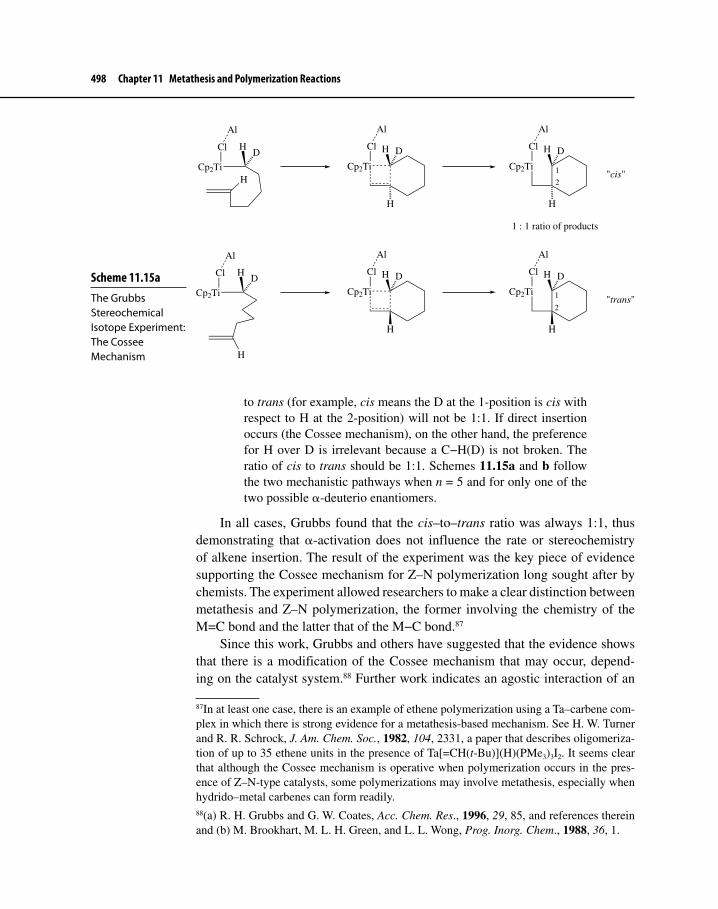
498 Chapter 11 Metathesis and Polymerization Reactions
to trans (for example, cis means the D at the 1-position is cis with respect to H at the 2-position) will not be 1:1. If direct insertion occurs (the Cossee mechanism), on the other hand, the preference for H over D is irrelevant because a C−H(D) is not broken. The ratio of cis to trans should be 1:1. Schemes 11.15a and b follow the two mechanistic pathways when n = 5 and for only one of the two possible α-deuterio enantiomers.
In all cases, Grubbs found that the cis–to–trans ratio was always 1:1, thus demonstrating that α-activation does not influence the rate or stereochemistry of alkene insertion. The result of the experiment was the key piece of evidence supporting the Cossee mechanism for Z–N polymerization long sought after by chemists. The experiment allowed researchers to make a clear distinction between metathesis and Z–N polymerization, the former involving the chemistry of the M=C bond and the latter that of the M−C bond.87
Since this work, Grubbs and others have suggested that the evidence shows that there is a modification of the Cossee mechanism that may occur, depend-ing on the catalyst system.88 Further work indicates an agostic interaction of an
87In at least one case, there is an example of ethene polymerization using a Ta–carbene com-plex in which there is strong evidence for a metathesis-based mechanism. See H. W. Turner and R. R. Schrock, J. Am. Chem. Soc., 1982, 104, 2331, a paper that describes oligomeriza-tion of up to 35 ethene units in the presence of Ta[=CH(t-Bu)](H)(PMe3)3I2. It seems clear that although the Cossee mechanism is operative when polymerization occurs in the pres-ence of Z–N-type catalysts, some polymerizations may involve metathesis, especially when hydrido–metal carbenes can form readily.88(a) R. H. Grubbs and G. W. Coates, Acc. Chem. Res., 1996, 29, 85, and references therein and (b) M. Brookhart, M. L. H. Green, and L. L. Wong, Prog. Inorg. Chem., 1988, 36, 1.
Scheme 11.15a The Grubbs Stereochemical Isotope Experiment: The Cossee Mechanism
Cl
Cp2Ti
Al
H
HD
Cp2Ti
Cl
Al
H D
H
Cp2Ti
Cl
Al
H D
H
"cis"
Cl
Cp2Ti
Al
HD
H
Cp2Ti
Cl
Al
H D
H
Cp2Ti
Cl
Al
H D
H
"trans"
1
2
1
2
1 : 1 ratio of products
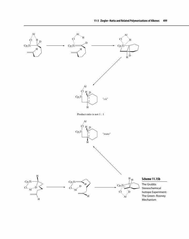
11-3 Ziegler–Natta and Related Polymerizations of Alkenes 499
Scheme 11.15b The Grubbs Stereochemical Isotope Experiment: The Green–Rooney Mechanism
Cl
Cp2Ti
Al
H
HD
Cl
Cp2Ti
Al
H
H
DCl
Cp2Ti
Al
H
H
D
Cp2Ti
Cl
Al
H D
H
"cis"
Cp2Ti
Cl
Al
H D
H
"trans"
1
2
1
2
Product ratio is not 1 : 1
Cp2Ti
H
H
ClAl
D
Cp2TiH
H
ClAl
D Cp2Ti
HH
DCl
Al

500 Chapter 11 Metathesis and Polymerization Reactions
α-hydrogen may occur before or during the M−C insertion step. Scheme 11.16 shows this modification.
For example, use of a neutral Sc–metallocene catalyst (45) shows kinetic deuterium isotope effects that were not present with Grubbs Ti system.89 It appears that deuterium isotope effects occur if insertion is rate-determining and if overall the rate of polymerization is relatively slow.
ScHPMe3
Me2Si
45
11-3-2 Stereochemistry of Z–N PolymerizationPolymerization of monosubstituted alkenes introduces stereogenic centers along the carbon chain at every other position. When, for example, propene undergoes Z–N polymerization, several possible geometries are possible, including isotactic, syndiotactic, heterotactic, hemiisotactic, and atactic (Figure 11-3).90
89W. E. Piers and J. E. Bercaw, J. Am. Chem. Soc., 1990, 112, 9406 and J. E. Bercaw, et al., In Ziegler Catalysts, G. Fink, R. Mühlhaupt, and H. H. Brintzinger, Eds., Springer–Verlag: Berlin, 1995, pp. 317–331.90G. W. Coates, Chem. Rev., 2000, 100, 1223.
Scheme 11.16 Modified Cossee Mechanism Showing an α-Agostic Interaction
M
P
+
R
M
P
R
M
H
H RP H
H
α-Agosticinteraction
M
RH
H
P
M
R
PH
H
H
H

11-3 Ziegler–Natta and Related Polymerizations of Alkenes 501
Note that isotactic polymers have all substituent groups (called pendant groups) on the same side of the chain; syndiotactic polymers maintain alternating stereochemistry for the pendant groups; heterotactic chains have alternating ste-reochemistry for each dyad, hemiisotactic polymers show the same stereochem-istry at every other pendant group, but the intervening pendant group has random stereochemistry; and atactic polymers display a random stereochemical arrange-ment of substituents throughout the polymer chain (the stereochemistries that are perhaps most common and well studied are isotactic and syndiotactic). All of these types of PP have been prepared, each with rather different mechanical properties. The potential existed early on to produce hundreds of polyalkenes, not only with different composition caused by change in pendant group, but also with several different kinds of tacticities. In the years since Natta’s first discovery of isotactic PP, progress in the design of catalysts capable of producing polymers with specific stereochemistry has been substantial.
Even today, however, there is not complete understanding of how different stereochemistries result from different catalyst systems, especially under hetero-geneous conditions. In general, Ti–Al catalysts tend to give isotactic and atactic PP, whereas VCl4–AlEt2Cl gives mainly the syndiotactic polymer.
A real advancement in the development of Z–N catalysts came when metal-locene catalysts were discovered.91 Now discrete, single-site complexes of early-transition metal metallocenes could be synthesized and characterized. These not only were potentially useful on an industrial scale, but also served as useful model systems for studying the mechanism and stereochemistry of Z–N catalysis. With the advent of high-level DFT–MO methods that were parameterized for all tran-sition metals, metallocene catalysts and the attendant polymerization processes could be easily modeled to help understand the stereochemical outcomes of Z–N
91For some reviews on metallocene Z–N catalysts, see H. Sinn, W. Kaminsky, H.–J. Vollmer, and R. Woldt, Angew. Chem. Int. Ed. Engl., 1980, 19, 390; H. H. Brintzinger, D. Fischer, R. Mühlhaupt, B. Rieger, and R. M. Waymouth, Angew. Chem. Int. Ed. Engl., 1995, 34, 1143; and G. G. Hlatky, Coord. Chem. Rev., 1999, 181, 243.
Figure 11-3 Some Common Stereochemistries Resulting from Z–N Polymerization of Propene and Other 1-Alkenes
MeZ-N catalyst
Isotactic
Syndiotactic
Heterotactic
Hemiisotactic
Atactic

502 Chapter 11 Metathesis and Polymerization Reactions
catalysis and to verify the mechanistic work of Cossee, Green and Rooney, and Grubbs.
For example, homogeneous Zr complexes, with rigid, cyclic π ligands, mixed with methylalumoxane ([Al(CH3)-O]n, abbreviated MAO) catalyze Z–N polymerization to give stereoregular polymers. MAO acts as an in situ methy-lating agent that replaces a Cl ligand on Zr with CH3. Equation 11.30 shows formation of isotactic PP using the chiral, ethano-bridged, bis-tetrahydroindenyl Zr complex 46.92
ZrCl
Cl
46
MAOMe
n
11.30
Syndiotactic polymerization, shown in equation 11.31, occurs with the Cp–fluorenyl Zr complex 47.93 Note that 47 possesses a plane of symmetry bisecting the two cyclic π ligands, whereas 46 is a chiral molecule, possessing a C2 symmetry axis94 but no symmetry plane.
XMe
Me
Zr
Cl
Cl
X = C, Si
47Men
MAO
11.31
There has been a great deal of effort reported designed to make sense of how different metallocene complexes regulate polymer tacticity as a function of the symmetry properties of the catalyst. To begin to understand this, we must look at stereochemical possibilities of approach by propene to the metal. Figure 11-4 shows four such options, which may be classified as re-primary, si-primary, si-secondary, and re-secondary. The designations re and si refer to the faces of the propene C=C bond, and Figure 11-4 also details the difference between si
92W. Kaminsky, W. K. Kulper, H. H. Brintzinger, and F. R. W. P. Wild, Angew. Chem. Int. Ed. Engl., 1985, 24, 507.93J. A. Ewen, R. L. Jones, and A. Razavi, J. Am. Chem. Soc., 1988, 110, 6255.94A molecule that possesses a C2 symmetry axis may be rotated by 360o/2 (or 180o) to obtain a geometry equivalent to the starting geometry. In general, a Cn axis corresponds to rotation by 360o/n. Chiral molecules typically possess no elements of symmetry or only Cn axes. Molecules that possess a plane of symmetry are necessarily achiral.

11-3 Ziegler–Natta and Related Polymerizations of Alkenes 503
and re.95 The primary and secondary descriptors designate whether the polymer chain grows with a primary carbon attached to the metal or a secondary carbon (Figure 11-5). The primary approach seems more likely, based on a lower steric effect, for metallocene catalysts.
We can generalize, based on our understanding of the different approach modes of the alkene to the metal, by saying that isotactic polymers result from multiple insertions of the alkene to the same enantioface (re or si) and syn-diotactic chains form from regular alternations for complexation and insertion
95The terms re and si describe the prochiral nature of the two faces of an alkene such as pro-pene. To determine which term applies, one looks at a face of the alkene and assigns priori-ties (using the Cahn–Ingold–Prelog rules) to the substituents attached to the more substituted carbon of the C=C bond. The =CH2 group has the highest priority, followed by CH3, and finally by H. If a clockwise motion connects these groups on the basis of highest, medium, and lowest priorities, then the face that the observer is looking at is designated re. A counter-clockwise motion would give si. For additional information, see E. L. Eliel and S. H. Wilen, Stereochemistry of Organic Compounds, Wiley: New York, 1994, pp. 484–486.
Figure 11-4 Modes of Approach and Insertion of Prochiral Propene onto a Metal Site and Growing Polymer Chain
Me
M P
P
M P
Me
M P
Me
M P
Me
: Growing polymer chain
si-primary
re-primary
re-secondary
si-secondary
Figure 11-5 Primary and Secondary Insertion of Propene in a Growing Polymer Chain
Me
M P M Me
P
M P
Me
M
PMe
Primary insertion:
Secondary insertion:

504 Chapter 11 Metathesis and Polymerization Reactions
of the alkene at the metal enantioface (re then si then re, etc.).96 Scheme 11.17 shows a possible mechanism for the origin of syndiotacticity in a polymerization catalyzed by Zr metallocene 48, which is similar in structure to 47.97 Isotactic polymerization shows influence of both the metal enantioface and the steric bulk of the growing polymer chain.98
Metallocene-catalyzed Z–N polymerization is finding increased use on an industrial scale. One application is the production of linear low-density polyeth-ylene (mLLDPE),99 which is a linear polymer with short branches incorporated deliberately at various points along the chain. Short branches are produced by Z–N copolymerization of ethene with 1-butene, 1-pentene, and 1-hexene rather than through radical mechanisms of chain transfer and backbiting. Thus, the process is
96P. Corradini, G. Guerra, and L. Cavallo, Acc. Chem. Res., 2004, 37, 231.97See Footnote 88a.98For additional discussion of the factors that direct either isotactacity or syndiotacticity, see Footnotes 88a, 90, 96, and A. Motta, I. L. Fragalà, and T. J. Marks, J. Am. Chem. Soc., 2007, 129, 7327.99The letter m refers to the use of metallocene catalysts for the production LLDPE. Other Z–N catalysts could also be used, but metallocenes provide LLDPE with superior mechanical properties.
Scheme 11.17 A Possible Mechanism for Syndiotactic Polymerization of Propene
Zr
Cp'
Fr
H
PH
H Me
Me Zr
Cp'
Fr
MeH
H MeP
Zr
Cp'
Fr
H MeP
MeH
Zr
Cp'
Fr P
H Me
HMe
H
H
Zr
Cp'
Fr H
Me
HMeMe
HP
Zr
Cp'
Fr
H
Me
MeHH
MeP
Fluorene (Fr)
MeMe
ZrClCl
Isopropylcyclopentadiene (Cp')
P = P or P
H MeMe H
re-insertion
si-insertion
R
RR
S
S
R
R
R S
SR
48

11-3 Ziegler–Natta and Related Polymerizations of Alkenes 505
a linear polymerization, except there is more than one monomer present. Several oil and petrochemical companies have invested heavily in this technology to pro-duce mLLDPE, a material that has better properties than low-density PE for use as films and packaging materials.
11-3-3 Polymerizations Catalyzed by Late Transition Metal ComplexesOver the past 15 years, a very active area of organometallic chemistry has devel-oped, which has the goal of using late transition metal catalysts to promote polymerization of ethene and 1-alkenes.100 We have seen already in the SHOP process the use of a Ni catalyst in the oligomerization of ethene. Extending this to the polymerization of ethene to high molecular weights could have several advan-tages over other means of polymerization: (1) unlike Z–N catalysts, late transition metal catalysts should be tolerant of oxygen and nitrogen functional groups on monomers. Thus, copolymerization with acrylate esters or vinyl acetate, which is normally done using radical catalysts and which produces commercially useful materials, could be accomplished by such catalysts. (2) Late transition metal cata-lysts also accommodate the presence of air and moisture, which is not the case with Z–N catalysts. (3) Highly active late-transition metal catalysts should allow polymerization of ethene under mild conditions, which is in contrast to the high temperature and pressures used to do this reaction using radical catalysts.
Late-transition metal catalysts became a reality as a result of the efforts of Brookhart and co-workers, who discovered a number of highly active cationic Ni
100Also known as α-olefins.
Using the transformations described in equations 11.30 and 11.31 as a guide, what stereochemistry would you expect for PP when 49 (the meso form of 46) is used as a co catalyst instead of one of the enantiomers of 46? Explain (see Footnote 90).
ZrCl
Cl
49
Exercise 11-11

506 Chapter 11 Metathesis and Polymerization Reactions
and Pd catalysts and first reported on these in 1995.101 These compounds pro-moted polymerization of ethene to materials of high molecular weight and were well suited for this task for several reasons: (1) the soft, cationic metal centers are of sufficient electrophilicity that they readily bind to π bonds and subsequently allow for 1,2-insertion. (2) The presence of sterically bulky diimine ligands helps to prevent β-elimination, which normally occurs with late transition metal alkyl ligands. (3) The presence of a non- or weakly- coordinating ligand allows for ease of binding of ethene. Structures 50, 51, and 52 show examples of these catalysts or precatalysts (MAO or Na[B(ArF)4], where ArF = 3,5-bis(trifluoromethyl)phe-nyl, is also present as needed to remove a halide ligand and to create an open coordination site).
N N
Ni
Br Br
50
N N
PdO
MeO
51
N N
NiAr'
Ar'Ar'
Ar' BrBr
52
Ar' = t-Bu
Scheme 11.18 shows a reasonable mechanism for polymerization that con-sists of first complexation of alkene, followed by 1,2-insertion. Ideally, the two steps will continue until synthesis of high-molecular-weight polymer occurs. Chain growth will cease if chain transfer occurs. Scheme 11.19 indicates two possible mechanisms for chain transfer, both of which are reasonable and indis-tinguishable by experiment. In both cases, the steric bulk of the diimine ligand seems to hinder the transfer process.102
101L. K. Johnson, C. M. Killian, and M. Brookhart, J. Am. Chem. Soc., 1995, 117, 6414. 102S. D. Ittel, L. K. Johnson, and M. Brookhart, Chem. Rev., 2000, 100, 1169 and S. Mecking, Angew. Chem. Int. Ed., 2001, 40, 534.

11-4 σ Bond Metathesis 507
α-Olefins also polymerize in the presence of Ni and Pd catalysts, and the properties of these materials are quite different from those resulting from Z–N polymeriza-tion. So far, there has not been a significant commercial application of Ni- or Pd-catalyzed α-olefin or ethene polymerization. On the other hand, there has been much serious and useful collaboration already between industry and aca-demia on the use of such processes. The ease of producing materials that could have useful commercial application suggests that there will be industrial uses for this process in the future.103
11-4 σ BOND METATHESISIn Chapter 7 (Section 7-2-1), we discussed activation of nonpolar bonds, such as C−H, C−C, and H−H via oxidative addition to a metal center, as having
103For additional information on olefin polymerization, catalyzed by late transition metals, see G. W. Coates, P. D. Hustad, and S. Reinartz, Angew. Chem. Int. Ed., 2002, 41, 2236.
Scheme 11.18 Mechanism of Ethene Polymerization Catalyzed by Late-Transition Metal Complexes
N
M
R'
N
R
R
N
M
R'
N
R
R
N
M
N
R
RH
R'
N
M
N
R
R
R'N
M
N
R
RH
R'etc.
Chain branching in ethene polymerization is catalyzed by Ni and Pd complexes through a process called “chain migration” or “walking.” A series of β-eliminations and 2,1-insertions occurs as the metal “walks” along the growing polymer chain. A pause in this process allows 1,2-insertion to continue from the point of metal attachment along the polymer chain; thus, branching results. Show with a mechanism how this could give chain branches of three ethylene units.
Interestingly, as the pressure of ethene increases, the amount of chain branching decreases. Explain.
Exercise 11-12
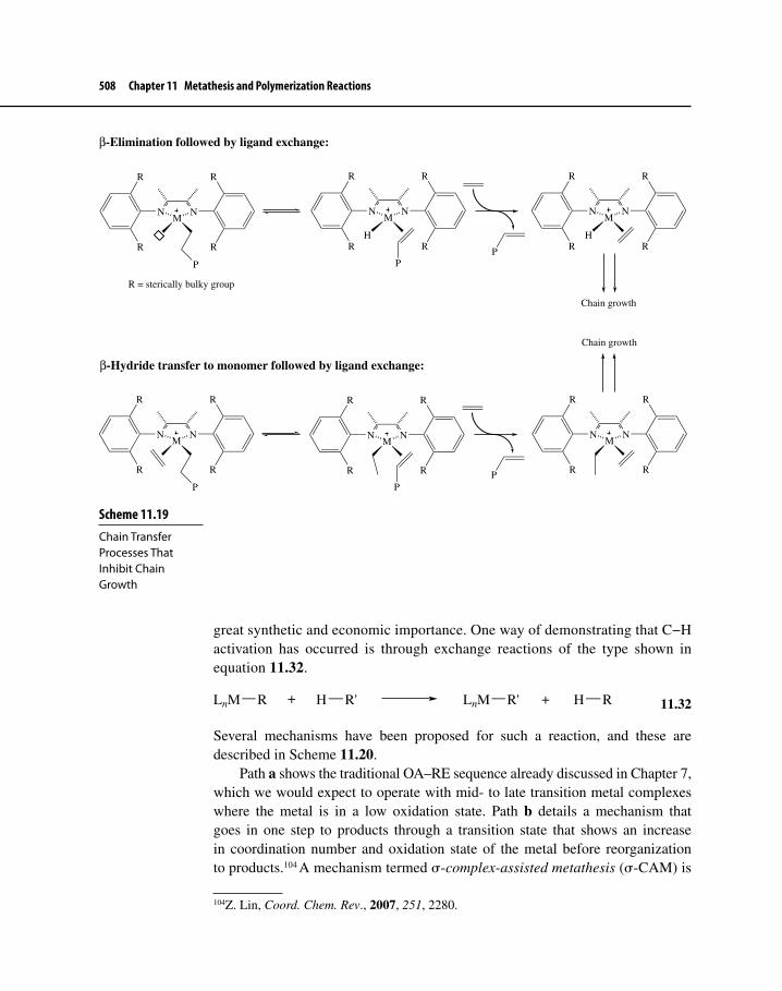
508 Chapter 11 Metathesis and Polymerization Reactions
great synthetic and economic importance. One way of demonstrating that C−H activation has occurred is through exchange reactions of the type shown in equation 11.32.
LnM R + H R' LnM R' + H R
11.32
Several mechanisms have been proposed for such a reaction, and these are described in Scheme 11.20.
Path a shows the traditional OA–RE sequence already discussed in Chapter 7, which we would expect to operate with mid- to late transition metal complexes where the metal is in a low oxidation state. Path b details a mechanism that goes in one step to products through a transition state that shows an increase in coordination number and oxidation state of the metal before reorganization to products.104 A mechanism termed σ-complex-assisted metathesis (σ-CAM) is
104Z. Lin, Coord. Chem. Rev., 2007, 251, 2280.
Scheme 11.19 Chain Transfer Processes That Inhibit Chain Growth
NM
N
R
R
R
R
P
NM
N
H
R
R
R
R
PP
NM
N
H
R
R
R
R
Chain growth
NM
N
R
R
R
R
P
NM
N
R
R
R
R
PP
NM
N
R
R
R
R
Chain growth
β-Hydride transfer to monomer followed by ligand exchange:
β-Elimination followed by ligand exchange:
R = sterically bulky group

11-4 σ Bond Metathesis 509
Scheme 11.20 Mechanisms for C−H activation
LnM R + H R' LnMR
R'H
LnM
R
H
R'
LnM
R'
R
HLnM R' + H R
LnM R + H R' LnM
R
H
R'
LnM R' + H R
LnM R + H R'
LnM
RR'H
LnM
RR'H
LnMR
R' HLnM R' + H R
LnM R + H R'
R'
H
R
LnM LnM R' + H R
Path a:
Path b:
Path c:
Path d:
outlined in path c. This pathway shows no change in oxidation state of the metal, and it requires the presence of discrete intermediates.105 Finally, path d portrays a one-step pathway that goes through a four-center transition state where the oxida-tion state of the metal does not change. This last pathway, called σ- bond metath-esis (SBM), is associated with d0 complexes of early transition metals as well as lanthanides and actinides, which cannot undergo OA. It is clear from intense research interest in SBM as well as in other paths to C−H and C−C bond activa-tion over the past 20 years that a continuum of mechanistic possibilities exists for the type of exchange reaction that is shown in equation 11.32, with paths a and d existing at the two ends of the mechanistic spectrum.
Although it is not obvious that the following reaction (equation 11.33) actu-ally occurs via path b, theoretical analysis using DFT of the reaction (PR3 = PH3) indicates that a one-step OA pathway occurs that goes through a transition state as shown in Scheme 11.20.106
Tp(PH3)M
CH3
CH3
H Tp(PH3)M CH3
H3C H
M = Fe, Ru
11.33
105R. N. Perutz and S. Sabo-Etienne, Angew. Chem. Int Ed., 2007, 46, 2578.106W. H. Lam, G. Jia, Z. Lin, C.P. Lau, and O. Eisenstein, Chem. Eur. J., 2003, 9, 2775.

510 Chapter 11 Metathesis and Polymerization Reactions
Reactions of the type shown in equation 11.34 have been run by Hartwig and thoroughly analyzed by theory at the DFT level. A reasonable explanation for the borylation of alkanes and arenes is the σ-CAM mechanism via path c.107
Cp*(CO)2Fe B
O
O
hνCp*(CO)2Fe H + B
O
O
11.34
The remainder of this section will focus on true SBMs, which have been the subject of vigorous research. Despite the electron deficiency of early tran-sition metal, lanthanide, and actinide complexes, several groups reported that some of these d0f n complexes do react with the H−H bond from dihy-drogen and C−H bonds from alkanes, alkenes, arenes, and alkynes in a type of exchange reaction shown in equation 11.32. So many examples of SBM involving early, middle, and late transition metal complexes have appeared in the chemical literature over the past 20 years that chemists now consider this reaction to be another fundamental type of organometallic transformation along with oxidative addition, reductive elimination, and others that we have already discussed.
As with olefin metathesis, we may consider a true SBM to be formally a 2 + 2 cycloaddition, but unlike its π bond counterpart, SBM does not require the forma-tion of a four-membered ring intermediate. Instead, a four-center, four-electron transition state occurs along the reaction coordinate, which calculations have shown to be kite-shaped. In ordinary organic reactions, 2 + 2 cycloadditions— whether they involve σ or π bonds—are disallowed108 under thermal conditions. Organometallic metatheses, on the other hand, involve a metal that has the ability to utilize not only s and p orbitals but also d and f (in the case of the lanthanides and actinides) orbitals, singly or in combination. Figure 11-6 shows how molec-ular orbitals of starting material, transition state, and products correlate well in a pathway involving a low-energy transition state.109 There is continuous bond-ing along the reaction coordinate for all the occupied orbitals, the hallmark of
107C. E. Webster, Y. Fan, M. B. Hall, D. Kunz, and J. F. Hartwig, J. Am. Chem. Soc., 2003, 125, 858 and J. F. Hartwig, K. S. Cook, M. Hapke, C. D. Incarvito, Y. Fan, C. E. Webster, and M. B. Hall, J. Am. Chem. Soc., 2005, 127, 2538.108The term “disallowed” means that, for the reaction to occur in a concerted fashion, the reaction coordinate must pass through a high-energy transition state. Lower-energy paths may be possible, but these would involve a non-concerted mechanism with radical or charged intermediates.109Note that the MOs for the transition state represent a σ bond analogy to the bonding and non-bonding π MOs of the allylic system.

11-4 σ Bond Metathesis 511
a concerted, thermally allowed reaction. Note how the hydrogen appears at the position farthest to the right or the top of the “kite,” also known as the B-position, in the transition state. This is caused by the spherical nature of the hydrogen s orbital that can best accommodate the angular overlap required at that position. Were carbon to occupy this position, the orbitals available would be shaped to point in a specific direction and thus unable to overlap smoothly with other orbitals
Figure 11-6 Molecular Orbital Correlation Diagram for σ Bond Metathesis
Cp2Sc CH3 + H−R Cp2Sc R + H−CH3
R = Alkyl
Sc
C
R
H
R
C
Sc H
C
R
HSc
C
Sc
R
H
R
C
HSc
Sc
R
C
H
R
HCp2Sc
CH3 CH3
HCp2Sc
R
CH3
H
R
Cp2Sc
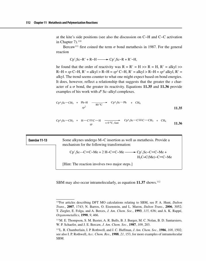
512 Chapter 11 Metathesis and Polymerization Reactions
at the kite’s side positions (see also the discussion on C−H and C−C activation in Chapter 7).110
Bercaw111 first coined the term σ bond metathesis in 1987. For the general reaction
Cp*2Sc−R′ + R−H Cp*
2Sc−R + R′−H,
he found that the order of reactivity was R = R′ = H >> R = H, R′ = alkyl >> R−H = sp C−H, R′ = alkyl > R−H = sp2 C−H, R′ = alkyl > R−H = sp3 alkyl, R′ = alkyl. The trend seems counter to what one might expect based on bond energies. It does, however, reflect a relationship that suggests that the greater the s char-acter of a σ bond, the greater its reactivity. Equations 11.35 and 11.36 provide examples of his work with d0 Sc–alkyl complexes.
Cp*2Sc CH3 + Ph−H80 oC
Cp*2Sc Ph + CH4
sp2
11.35
Cp*2Sc CH3 +< 0 oC, fast
Cp*2Sc C + CH4
spC C HH C CH3
11.36
SBM may also occur intramolecularly, as equation 11.37 shows.112
110For articles describing DFT MO calculations relating to SBM, see P. A. Hunt, Dalton Trans., 2007, 1743; N. Barros, O. Eisenstein, and L. Maron, Dalton Trans., 2006, 3052; T. Ziegler, E. Folga, and A. Berces, J. Am. Chem. Soc., 1993, 115, 636; and A. K. Rappé, Organometallics, 1990, 9, 466.111M. E. Thompson, S. M. Baxter, A. R. Bulls, B. J. Burger, M. C. Nolan, B. D. Santarsiero, W. P. Schaefer, and J. E. Bercaw, J. Am. Chem. Soc., 1987, 109, 203.112L. R. Chamberlain, I. P. Rothwell, and J. C. Huffman, J. Am. Chem. Soc., 1986, 108, 1502; see also I. P. Rothwell, Acc. Chem. Res., 1988, 21, 153, for more examples of intramolecular SBM.
Exercise 11-13 Some alkynes undergo M−C insertion as well as metathesis. Provide a mechanism for the following transformation:
Cp*2Sc—C≡C−Me + 2 H−C≡C−Me Cp*
2Sc−C≡C−Me + H2C=C(Me)−C≡C−Me
[Hint: The reaction involves two major steps.]

11-4 σ Bond Metathesis 513
D3C TaCD3
CD3
O
O
H
∆ D3C TaCD3
CD3
O
O
H
D3C TaCD3
O
O
CH2
+ CD3H
11.37
The involvement of SBM in alkene polymerization is another area of research interest. Although chain growth in Z–N polymerization occurs by 1,2-insertion into an M−C bond, chain termination may involve SBM. For example, H2 is some-times added to curtail the length of polymer chains. Watson113 observed that H2 reacts with Lu–alkyls according to equation 11.38. The reaction is undoubtedly a SBM and, as such, may provide a good model for what actually occurs when H2 is used to limit polyalkene chain length.
Cp*2Lu (CH2CH)nR'
R
H2Cp*2Lu H H (CH2CH)nR'
R
+
11.38
Silyl hydrides also undergo SBM, and equations 11.39 and 11.40 show some recent results. In the second example the silane is more sterically hindered.
Cp*2Sc CH3 + PhSiH3 Cp*2Sc H + PhSi(CH3)H2
11.39
Cp*2Sc CH3 +
Me
Me
Me SiH3
Cp*2Sc SiH2
Me
Me
Me + CH4
11.40
113P. L. Watson and G. W. Parshall, Acc. Chem. Res., 1985, 18, 51, and references therein.
Besides β-elimination and the addition of dihydrogen, another mechanism to limit chain length during Z–N polymerization is called chain transfer (see Scheme 11.13a). In this process, the growing polymer detaches from the metal center by exchanging places with monomer or another free polymer chain. Could a mechanism involving SBM rationalize this phenomenon? Explain.
Exercise 11-14

514 Chapter 11 Metathesis and Polymerization Reactions
DFT calculations showed that a four-center transition state was involved in both cases, but the transition states must be different for there to be two different sets of products. For the simplified reactions shown in Scheme 11.21, these calcu-lations also showed that the transition states (structures 53 and 54) leading to the two different product outcomes are remarkably similar in energy.114
Metathesis reactions that involve carbene complexes as intermediates have many useful industrial applications, and they play a key role in the synthesis of a large number of molecules of biological interest. Metathesis polymerizations lead to the production of materials with unique physical and chemical proper-ties. Although we now know that the production of stereoregular polymers by Z–N catalysis does not involve metal–carbene complexes, the chemistry associ-ated with this type of polymerization is linked to that of metal carbenes through early mechanistic investigations. The last section of Chapter 11 demonstrated that another type of metathesis exists in which σ M−C bonds, especially those involv-ing the early-transition metals, interact with other σ bonds. σ Bond metathesis now ranks with oxidative elimination and 1,2-insertion as a fundamental organo-metallic reaction type.
Suggested Readings
π Bond Metathesis—GeneralL. Delaude and A. F. Noels, “Metathesis,” in Kirk–Othmer Encyclopedia of Chemical
Technology, Wiley: New York, 2005, Vol. 26, pp. 920–958.R. H. Grubbs, Tetrahedron, 2004, 60, 7117.Handbook of Metathesis, R. H. Grubbs, Ed., Wiley–VCH: Weinheim, Germany, 2003,
Vol. 1–3. This compendium has chapters on all aspects of π bond metathesis.
114The silicon atom is bigger than carbon, so it can exist at the position at the top of the “kite” more readily than carbon. For more details, see A. D. Sadow and T. D. Tilley, J. Am. Chem. Soc., 2005, 127, 643.
Scheme 11.21 Two Product Outcomes from SBM of Cp2ScCH3 + SiH4
Cp2ScCH3 + SiH4
CH3
SiH3
H
Cp2Sc
CH3
H
SiH3
Cp2Sc
Cp2ScH
+
H3SiCH3
Cp2ScSiH3
+
CH4
Exercise 11-15 Reexamine the two different outcomes shown in equations 11.39 and 11.40. Propose an explanation for this difference.

Problems 515
R. H. Grubbs, T. M. Trnka, and M. S. Sanford, “Transition Metal–Carbene Complexes in Olefin Metathesis and Related Reactions,” in Fundamentals of Molecular Catalysis, H. Kurosawa and A. Yamamoto, Elsevier: Amsterdam, 2003, Chap. 4.
A. M. Rouhi, Chem. Eng. News, December 23, 2002, pp. 29–33.
π Bond Metathesis Mechanism and CatalystsC. P. Casey, J. Chem. Ed., 2006, 83, 192.D. Astruc, New J. Chem., 2005, 29, 42.R. R. Schrock and A. H. Hoveyda, Angew. Chem. Int. Ed., 2003, 42, 4592.A. M. Rouhi, Chem. Eng. News, December 23, 2002, pp. 34–38.
π Bond Metathesis ApplicationsA. H. Hoveyda and A. R. Zhugralin, Nature, 2007, 450, 243.J. C. Mol, J. Mol. Catal. A, 2004, 213, 39.K. J. Ivin and J. C. Mol, Olefin Catalysis and Metathesis Polymerization, Academic
Press: New York, 1997.
Alkyne MetathesisSee Chap. 1.12, 2.5, 2.12, 3.10, and 3.11 in the Handbook of Metathesis listed above.
Ziegler–Natta and Related Olefin PolymerizationsP. Corradini, J. Polym. Sci., Part A. Polym. Chem., 2004, 42, 391.R. Blom, A. Follestad, E. Rytter, M. Tilset, and M. Ystenes, Eds., Organometallic
Catalysts and Olefin Polymerization, Springer Verlag: New York, 2001.S. D. Ittel, L. K. Johnson, and M. Brookhart, Chem. Rev., 2000, 100, 1169.
Problems11-1 Propose a mechanism that would explain the following transformation.
Note that no other reagents are required for the reaction.
(CO)5Cr
Ph
OOMe (CO)5Cr
H
OMe
+
O
Ph
11-2 Propose a mechanism for the following transformation, which was cat-alyzed by Grubbs’ second-generation catalyst (structure 24, Section 11-1-2).115
115K. C. Nicolaou, J. A. Vega, and G. Vassiligiannakis, Angew. Chem. Int. Ed., 2001, 40, 4441.

516 Chapter 11 Metathesis and Polymerization Reactions
O
O O
OH
H
H
H
24
O
OO
O
H
H
H
H
HH
11-3 Grubbs’ second-generation catalyst also catalyzes cross metathesis of compound A with 2-methyl-2-butene. Predict the products of this trans-formation. The 1H NMR spectrum of one of the products (B) showed four singlets, each integrating to three protons, in the range δ 1.55 to 1.71 ppm in addition to a three-proton singlet at δ 4ppm. The other prod-uct (C) gave a simple 1H NMR spectrum with only four signals. Propose structures for compounds B and C.116
H O
O
H3C
CH3
OMe
A
11-4 The ROM polymerization of norbornene, catalyzed by Schrock catalyst D, is a living polymerization that can be halted by the addition of benz-aldehyde. This gives a polymer terminated at one end by CH=CH−Ph and at the other end by CH=CH−t-Bu. The byproduct is a tungsten oxide complex. Propose an explanation for the chain termination step.117
116S. J. Spessard and B. M. Stoltz, Org. Lett., 2002, 4, 1943.117G. Black, D. Maher, and W. Risse, “Living Ring-Opening Metathesis Polymerization,” in Handbook of Metathesis, Vol. 3, R. H. Grubbs, Ed., Wiley–VCH: Weinheim, Germany, 2003, p. 20.

Problems 517
n D W
N
t-BuOt-BuO
t-Bu
n
PhCHO
W
N
t-BuOt-BuO
t-Bu
n
Ph
O
+
W
N
t-BuOt-BuO
t-BuD
11-5 Metallacyclobutadienes are proposed as intermediates in metathesis reactions of alkynes. They formally may be considered derived from a metal and an allyl group:118
+
M M
y
x
a. Sketch the π orbitals of the allyl group. Also indicate the relative energies of these orbitals.
b. For each of the π orbitals, determine the metal orbitals suitable for interaction.
c. Which orbital on the metal would you expect to be most strongly involved in σ bonding with the end carbons?
11-6 The reaction conditions on the next page were used to produce a polymer by ROMP. Predict what the structure of the polymer will be.119
118Although there are two more hydrogen atoms in the system LnM + allyl than are present in a metallacyclobutadiene, the operative word in this problem is “formal.” Here, you are asked to interact only the orbitals from the metal and the allyl system that would produce the cor-responding orbitals in the metallacyclobutadiene.119T. M. Swager and R. H. Grubbs, J. Am. Chem. Soc., 1987, 109, 894.

518 Chapter 11 Metathesis and Polymerization Reactions
Ti CH2 +
(generated in situ)
11-7 Propose a reasonable catalytic cycle for the Ni-catalyzed oligomeriza-tion of ethene that occurs during the first stage of SHOP. Assume that the active catalyst is L(X)Ni−H.
11-8 Polyacetylene synthesis has long been a goal of polymer chemists and materials scientists because its rigid conjugated system could be an organic electrical conductor. Two approaches are outlined below. Propose mechanisms for how polyacetylene forms in both approaches. What are the structures of byproducts E and F?120
O ∆E +
n
n
F3C CF3
n
∆F + n
11-9 Draw the structure of a copolymer that could result from reaction with diene G and cyclooctene. Assume that the polymerization is catalyzed by Grubbs’, second-generation catalyst.
G
11-10 Consider the following transformation:
2 Ar−C≡N + Et−C≡C−Et Ar−C≡C−Ar + 2 Et−C≡N
120A. L. Safir and B. M. Novak, Macromolecules, 1993, 26, 4072 and L. Y. Park, R. R. Schrock, S. G. Stieglitz, and W. E. Crowe, Macromolecules, 1991, 24, 3489.

Problems 519
Ar = p-methoxyphenyl
The reaction is catalyzed by W complex H. Propose a mechanism for the reaction that accounts for both products and the overall stoichiometry.121
WO
O O
O
N
O
F3C
CF3
MeMe
F3C
F3C
Me
CF3F3C
Me
Me
H
11-11 Terminal dienes (also called α,ω-diolefins) are useful in ADMET polymerization. The scheme below shows a number of processes that were patented by Shell Oil Company and were designed to produce terminal dienes. The name FEAST (Further Exploitation of Advanced Shell Technology) was coined to describe these reactions, most of which involve metathesis. Assume that the catalyst is a generic carbene com-plex, LnM=CRR. Propose mechanisms for the transformations indicated by an asterisk near the reaction arrow.
H2C=CH2 H2C=CH2
3 H2C=CH2
n
2 H2
H2C=CH2
H2
H2C=CH2
*
*
*
121A. M. Geyer, R. L. Gdula, E. S. Wiedner, and M. J. A. Johnson, J. Am. Chem. Soc., 2007, 129, 3800.

520 Chapter 11 Metathesis and Polymerization Reactions
11-12 The copolymerization of ethene and CO produces an interesting polar material with alternating C2 alkane and carbonyl groups. If a monosub-stituted alkene is used, isotactic and syndiotactic polymers can result. The usual catalyst for such a process is a Pd–phosphine complex. If the phosphine ligand is chiral, stereoregularity with reference to the pendant group from the alkene can result.
a. Propose a mechanism for the copolymerization of ethene and CO, assuming that the catalyst is one of the cationic Brookhart complexes shown in Section 11-3-3.
b. Draw pictures of the isotactic and syndiotactic versions of a copolymer of styrene and CO.
11-13 Consider the C−H bond activation reaction involving a Tp–Ru complex shown. As the substituent X varies from an electron-donating group to an electron-withdrawing group, the rate of exchange increases. The authors of the study concluded that this result ruled out a classical OA–RE mech-anism and instead supported a mechanism resembling a SBM. Why did the researchers reach that conclusion? Explain.122
Tp
Ru
Me
Me3P
X
Tp
RuNCCH3
Me
Me3P
CH3CN
Ph−XTp
RuMe3P
X
+ Me−H
11-14 When Cp*2Sc−Me was allowed to react with d6-benzene (C6D6) at 125 oC,
a 1:1:1:1 mixture of CH3D, CH4, I, and J was obtained. Explain.
Cp*2ScD5
Sc
D5
Me
MeMe
MeMe
Me
CH2−D
Me
Me
Me
I
J
122N. J. DeYonker, N. A. Foley, T. R. Cundari, T. B. Gunnoe, and J. L. Petersen, Organometallics, 2007, 26, 6604.

Problems 521
11-15 The following reaction is catalyzed by Cp*2ScH.
Ph2SiH2 + CH4 Ph2MeSiH + H2
Two catalytic cycles were proposed for the overall transformation, one of which involved participation of one of the Cp* methyl groups and the other that did not. Draw the two possible catalytic cycles.123
123See Footnote 114.

Organic synthesis is the science and art practiced by chemists who concern themselves with the construction of carbon-containing molecules, many of which possess biological significance. Nature, of course, constitutes the pre-mier laboratory for the creation of organic compounds. Natural products—representing targets for laboratory synthesis—have provided chemists with tremendous challenges, which have been difficult and even impossible to meet using yesterday’s technology. The past 2 decades have seen an explosion of papers reporting new synthetic methods and descriptions of successful total syntheses of highly complex molecules. Of considerable assistance to synthesis chemists has been the development of new reagents and reaction conditions involving organometallic compounds, particularly complexes of the transition metals.
There are several approaches to describing the application of organotransi-tion metal chemistry to organic synthesis. For example, one could examine the field—metal by metal—reporting on uses for each element. Another strategy might be to scrutinize several syntheses of interesting molecules, each of which includes the use of organometallic reagents in key steps. The approach of Chapter 12, however, will be different. It will build upon the coverage in previous chapters of fundamental reaction types, catalytic processes, and metal–carbene complex chemistry and then use that knowledge to discuss some basic kinds of synthetic transformations. These transformation types are not necessarily tied to the use of only one of the transition metals; usually several different ones could work. Although coverage of the entire field of synthetic applications is impossible in
Applications of Organometallic Chemistry to Organic Synthesis
TWELVE
522

Chapter 12 Applications of Organometallic Chemistry to Organic Synthesis 523
one chapter,1 it is possible for the reader to appreciate the utility of transition metals by considering the following kinds of transformations, which are accom-panied by a typical example:
1. Enantioselective functional group interconversions.
MeO OMe
H CO2H
HN
Me
O
H2
[Rh-DIPAMP]+
MeO OMe
H CO2H
HN
Me
OH
(95% ee)
H
2. Carbon–carbon bond formation via nucleophilic attack on a π ligand.
OCO2Me
+MeO OMe
O− Na+O
L*Pd(II)
MeO2CCO2Me
(98% ee)
L* = chiral ligand
3. Carbon–carbon bond formation via carbonyl or alkene insertion
O
O
Me
Me
MeMe
OTf
CO/MeOH/DMF
Pd(OAc)2 (cat.)PPh3/Et3N O
O
Me
Me
MeMe
CO2Me
(75% yield)
1Entire books or major parts of some books cover the application of organometallic chemistry to organic synthesis. For some examples, see J. P. Collman, L. S. Hegedus, J. R. Norton, and R. G. Finke, Principles and Applications of Organotransition Metal Chemistry, University Science Books: Mill Valley, CA, 1987; Chap. 13–20; L. S. Hegedus, Transition Metals in the Synthesis of Complex Organic Molecules, 2nd ed., University Science Books: Mill Valley, CA, 1999; Handbook of Organopalladium Chemistry for Organic Synthesis, E. Negishi and A. DeMeijere, Eds., Wiley: New York, 2002; and Comprehensive Asymmetric Catalysis,E. N. Jacobsen, A Pfaltz, and H. Yamamoto, Eds., Supplement 1, Springer: New York, 2003. See the Suggested Readings section at the end of Chapter 12 for more sources on this topic.

524 Chapter 12 Applications of Organometallic Chemistry to Organic Synthesis
4. Carbon–carbon bond formation via transmetalation reactions
N
Ph
IEtO2C
CHO
SnBu3+
PdCl2(PPh3)3
DMF/80 oC/3 h N
Ph
EtO2C
CHO
(93% yield)
5. Carbon–carbon bond formation through cyclization reactions
NTs N
H
OTsCo2(CO)8 (cat.)
(S)-BINAP (cat.)
MeOCH2CH2OMe/∆(93% ee, 60% yield)
12-1 ENANTIOSELECTIVE FUNCTIONAL GROUP INTERCONVERSIONSThe ability to interconvert one functional group into another is of fundamental importance in organic synthesis. Often, these interconversions involve reduction or oxidation of a functional group, and such transformations also may either cre-ate or destroy a stereogenic center. The first part of Section 12-1 will explore transition metal-catalyzed hydrogenations of C=C and C=O bonds, which can exhibit a high degree of stereoselectivity. The second part will consider oxidation reactions that are also catalyzed by transition metal complexes, which can lead to enantioenriched products.
12-1-1 Asymmetric HydrogenationsThe double bond in an alkene is rich in its chemistry, and it undergoes transfor-mation to alcohols, alkyl halides, and alkanes depending upon reaction condi-tions. Although C=O and C=C bonds are planar and provide an achiral reaction site, the interaction of these functional groups with specific reagents often cre-ates one or more stereogenic centers in the reaction product, as reaction 12.1 shows.
ONaBH4
MeOH
HO H H OH
+
1 : 1
12.1

12-1 Enantioselective Functional Group Interconversions 525
In this case, the achiral reagents reacting via an achiral (or racemic) interme-diate in an achiral solvent should produce racemic product. Over 40 years ago, this is all we could expect of such a reaction in terms of stereoselectivity. If the purpose of the transformation was to obtain one or the other enantiomer, then special and often tedious methods were required to resolve the racemic product. Today, the goal of synthesis chemists often is to produce molecules that are not only chiral, but also enantiomerically pure. Biologically active molecules typi-cally exist in only one enantiomeric form. Efficacious drugs are also often most effective if they exist as only one enantiomer in order to interact properly with a chiral active site. A racemic drug is a mixture of enantiomers, only 50% of which is usually efficacious. The other 50% is at best worthless and at worst toxic, sometimes severely so.2
With the goal in mind of mimicking Nature or producing materials even more efficacious than those naturally occurring, chemists have discovered sev-eral methods for obtaining a particular enantiomer of a chiral compound. Among these are the following:
1. Chemical resolution of a racemate2. Chiral chromatography3. Use of chiral natural products as starting materials4. Stoichiometric use of chiral auxiliaries5. Asymmetric catalysis
Method 1 represents the oldest technique for producing selectively one enantiomer, and readers should already be familiar with it.3 A chromatography column normally is an achiral environment; elution of a racemate through the column should result in no separation into enantiomers. In Method 2, however, columns are modified by attaching chiral, enantioenriched groups to the solid support. Now a chiral environment does exist such that the two enantiomers exhibit diastereomerically different interactions with the column; this is the basis for separation. Chiral column chromatography can sometimes resolve
2The classic example of a racemic drug, one enantiomer of which is beneficial and the other toxic, is thalidomide. The efficacious enantiomer is a tranquilizer and the other isomer causes severe birth defects when given to pregnant women. Another example is naproxen, the (S)-enantiomer of which is an effective NSAID; the (R)-enantiomer, although modestly effective, is also a liver toxin at its therapeutically effective dose (which is much higher than the dose for the (S)-isomer). It was necessary to design a synthesis of naproxen that produced the (S)-enantiomer with high stereoselectivity. One approach to synthesis of (S)-naproxen involves an asymmetric hydrogenation as a key step.3For a brief discussion, see P. Y. Bruice, Organic Chemistry, 5th ed., Pearson Prentice Hall: New York, 2007, pp. 232–233, or almost any other current undergraduate-level organic chemistry textbook for similar information.

526 Chapter 12 Applications of Organometallic Chemistry to Organic Synthesis
racemates quite effectively, providing either enantiomer with a high degree of enantio purity.4
Allowing Nature to do part of the work is the central theme of Method 3. Numerous chiral molecules, isolated from natural sources and often available commercially, already contain much of the appropriate stereochemistry required in an enantioselective synthesis. These compounds are called the pool of chiral compounds. One reported synthesis of biotin (2), a molecule involved in enzy-matic transfer of CO2, used the methyl ester of the amino acid cysteine (1) as starting material.5 Note how 1 possesses a key stereocenter that later appears in biotin.
H−O2C
+H3N
HS
1
NHHN
S
O
CO2H
HHH
2
Attaching a chiral group to a reagent and then performing a reaction that goes through two possible diastereomeric transition states is the basis for Method 4. The presence of a chiral auxiliary provides an environment in which two path-ways—diastereomerically related—are possible between reactant and product. One pathway is usually lower in energy due to steric hindrance, and it is more favorable. The result, upon removal of the chiral auxiliary, is selection for one enantiomer over the other. Absence of the chiral auxiliary during the transforma-tion would produce a racemate because the transition state would be racemic. Scheme 12.1 shows an alkylation of a carboxylic acid to yield preferentially the R-enantiomer. The acid is first converted to a derivative, known as an oxazoline (3), which is non-racemic. Treatment of 3 with lithium diisopropyl amide (LDA), a very strong base, provides the enolate (4) that is then allowed to react with an electrophile (1-bromobutane in this case). The lithium ion can coordinate not only to the nitrogen and to the methoxy group but also to the halide ion of the incom-ing electrophile (if it attacks on the bottom face of the enolate). The bulky phenyl group, pointing upward, also tends to prevent attack on the top face of 4. These two factors raise the energy of the transition state that involves top face attack.
4For a discussion on chiral chromatography, see E. Juaristi, Introduction to Stereochemistry and Conformational Analysis, Wiley: New York, 1991, pp. 132–136.5E. J. Corey and M. M. Mehrotra, Tetrahedron Lett., 1988, 29, 57.

12-1 Enantioselective Functional Group Interconversions 527
The result, upon removal of the chiral auxiliary by hydrolysis, favors selection of the R-enantiomer in this case. There are several examples of use of Method 4 in the chemical literature,6 but the technique does suffer from one disadvantage—one reaction is required to add the chiral auxiliary and another to remove it.
Method 5, asymmetric catalysis, is similar to the fourth technique except that enantioselectivity results catalytically without requisite separate stoichiomet-ric steps for adding and later removing a chiral auxiliary. In light of increasing interest in applying the principles of green chemistry to organic transformations, Method 5 is perhaps the most environmentally benign approach to enantioselec-tivity. Atom economy is maximized, and the E-factor (see Section 9-1-5 for a
6For a review on the use of oxazoline chiral auxiliaries, see K. A. Lutonski and A. I. Meyers, “Asymmetric Syntheses via Chiral Oxazolines,” in Asymmetric Syntheses, Vol. 3, J. D. Morrison, Ed., Academic Press: San Diego, 1984, pp. 213-274; A. I. Meyers, Asymmetric Synth., 2007, 37, 37; and H. Nishiyama, J. Ito, T. Shiomi, T. Hashimoto, T. Miyakawa, and M. Kitase, Pure Appl. Chem., 2008, 80, 743.
Scheme 12.1 Enantioselective Synthesis Using a Chiral Auxliary
O
NCH2CH3
Ph
OMe 3
Steps
CH3CH2CO2H
LDA
THF
O
N
Ph
HO
Li 4
CH3
H
1-Bromobutane
O
N
Ph
O
LiMe
CH3
H
Br
O
N
Ph
OMe
H
CH3H3O+HO2C
H
CH3
(R)-

528 Chapter 12 Applications of Organometallic Chemistry to Organic Synthesis
discussion of atom ecomomy and E-factor) is minimized. Method 5, moreover, mimics Nature such that enzymes serve as giant chiral auxiliaries that bind sub-strates to active sites where chemical transformation can occur enantioselectively before the release of product. Organotransition metal catalysts in some cases duplicate the high stereoselectivity of enzymatic systems, and the remainder of Section 12-1 and later sections in Chapter 12 (see also some examples in Sections 9-7-2 and 9-7-3) will describe some of the most successful examples of asym-metric catalysis using organometallic complexes.
Asymmetric Hydrogenation Using Rhodium ComplexesSection 9-4-3 discussed an example of asymmetric hydrogenation in the synthesis of l-Dopa, pioneered by Knowles.7 We now have a good understanding of how Rh (I) complexes can catalyze the enantioselective addition of H2 across an unsym-metrical C=C bond, thanks to the work of Halpern and Brown.8 Scheme 12.2
7W. S. Knowles, Acc. Chem. Res., 1983, 16, 106, and references therein to his earlier work.8J. Halpern, Science, 1982, 217, 401; J. M. Brown and P. A. Chaloner, J. Am. Chem. Soc., 1980, 102, 3040; and J. M. Brown and D. Parker, Organometallics, 1982, 1, 950.
Scheme 12.2 Rh–DIPHOS-Catalyzed Hydrogenation of EAC
Rh
Ph2P
PPh2
2 H2
CH3OH (Solv)
Rh
Ph2P
PPh2
Solv
Solv
Rh(I)
RhPPh2
Ph2P
H
PhCO2Et
NH
MeO
Rh(I)
CO2Et
NHCOMe
H
Ph
6
5
7
H2
RhPPh2
Ph2P
H
H
Ph CO2Et
NH
Me
O
8
H
SolvRh
PPh2
Ph2P
CH2Ph
CO2EtNH
Me
O
Solv
HRh(III) Rh(III)
9
CO2Et
NHCOMe
PhCH2 H
10
DIPHOS
Solv

12-1 Enantioselective Functional Group Interconversions 529
shows the catalytic cycle for hydrogenation of ethyl (Z)-1-acetamidocinnamate (EAC, 5) using a cationic Rh(I)–DIPHOS complex (6) as the catalyst.
Because DIPHOS (or dppe) is an achiral ligand, the environment at the ini-tial stages in the cycle is racemic, and no enantioselectivity is possible. The most common ligands used in asymmetric hydrogenation are, however, chiral diphos-phines that usually possess a C2 symmetry axis; Figure 12-1 shows just a few of the hundreds and hundreds of diphosphine and related ligands that have been reported in the literature.
Halpern reasoned that if he could work out the essential features of the catalytic cycle using readily available DIPHOS, he could then apply this knowl-edge to hydrogenations using chiral ligands. Employing a combination of tech-niques, he was able to determine the rate constant for each step in the cycle and to characterize all intermediates except dihydride 8, formed during the rate- determining step. The formation of 8 does seem reasonable, however, based upon previous studies encountered already in Chapter 7 on the oxidative addi-tion of H2 to square planar Rh complexes. The other steps in the cycle should be quite familiar by now: 6 to 7 (ligand binding), 8 to 9 (1,2-insertion), and 9 to 6 (reductive elimination).
The presence of a chiral ligand, such as CHIRAPHOS, complicates the cycle because now there are two parallel pathways that are diastereomeric,9
9Because the CHIRAPHOS ligand possesses two stereocenters, the intermediates 7′ and 7″ are diastereometric and not mirror images.
Figure 12-1 Chiral Diphosphine Ligands
(S,S)-DIPAMP
p p
OMe
MeOPh2P PPh2
OO
H H
(R,R)-DIOP
PPh2
PPh2
(R)-BINAP
Me
Ph2P PPh2
MeH H
(S,S)-CHIRAPHOS
P P
Et
Et
Et
Et
(S,S)-Et-DuPHOS
O
O
O
O PPh2
PPh2
(R)-SEGPHOS

530 Chapter 12 Applications of Organometallic Chemistry to Organic Synthesis
Scheme 12.3 Mechanism of Asymmetric Hydrogenation Using Rh–CHIRAPHOS
NHCOMe
CO2EtH
Ph
RhPO
P
Me
HN
CO2Et
PhRh
P O
P
Me
NH
EtO2C
Ph
RhPO
H
Me
HN
CO2Et
Ph
P
H
RhP O
H
Me
NH
EtO2C
Ph
P
H
Rh
H
PSHNO
P
Me
EtO2C
Ph
Rh
H
P S NHO
P
Me
CO2Et
Ph
RhP
P S
S "Major" Manifold"Minor" Manifold
HN Me
O
EtO2C
Ph
HHNMe
O
CO2Et
Ph
H
6
8'8''
7'' 7'
9'9''
10'' 10'
Major Product
MinorProduct
H2H2
S(solvent)
S(solvent)
SS
k−1
k1
k−1
k1k2k2
k3 k3k4k4
5
(R) (S)
as shown in Scheme 12.3. Efforts to understand the chiral catalytic cycle were boosted by Halpern’s success in isolating 7′ and obtaining its crystal structure.
If hydrogen adds to 7′ in accord with the mechanism depicted in Scheme 12.2, then the final hydrogenation product should be N-acetyl-(S)-phenylalanine ethyl ester (10, Scheme 12.3). Halpern found, however, that the predominant product in the presence of CHIRAPHOS was the R-enantiomer (10″, Scheme 12.3)! Based on this result and other evidence, it was possible for Halpern to say that 7′ and 7″ form as an equilibrium mixture rapidly and reversibly from reaction of 5 and 6. Although 7′ is more stable than 7″, and thus is part of what Halpern termed the “major” manifold shown in Scheme 12.3, the less stable “minor” man-ifold isomer (7″) reacts much faster during rate-determining oxidative addition of H2, eventually leading to the R-amino acid derivative.

12-1 Enantioselective Functional Group Interconversions 531
The origin of enantioselectivity is thus the lower ∆G‡ for the path 7″ to 8″ than for 7′ to 8′. Figure 12-2 shows a free-energy versus reaction progress dia-gram for the rate-determining step.
Calculations show that 7′ is probably more stable than 7″ because the alkene ligand fits better into the pocket formed by the phenyl groups of the CHIRAPHOS ligand in 7′. The difference in free energy alone between 7′ and 7″ is insufficient to explain the relative rate difference leading to an enantiomeric excess of R- versus S-amino acid of 96%, that is if one assumes that ∆G is approximately equal to ∆∆G‡. To explain an ee of 96%, Halpern also speculated that there was a reversal in stability of the two products 8′ and 8″, with 8″ being more stable than 8′. More recent calculations show this to be the case.10 As Figure 12-2 shows, the higher energy of 7″ and the lower energy of 8″, when compared with their diastereomers, act synergistically to provide a much lower pathway for 7″ going to 8″ than for 7′ to 8′ (this is in agreement with the Hammond Postulate, see Section 7-1-3).
10Calculations performed using a different bisphosphine ligand showed a similar kinetic preference for the less stable diastereomer of the type shown above as 7″. See S. Feldgus and C. R. Landis, J. Am. Chem. Soc., 2000, 122, 12714.
Based on the stereochemistry associated with 1,2-insertion and reductive elimination, verify that, in Scheme 12.3, 8′ will transform ultimately into the S-amino acid derivative and 8″ into the R-enantiomer.
Exercise 12-1
Figure 12-2 Free-Energy versus Reaction Progress Diagram for the Rate-Determining Step of Asymmetric Hydrogenation
∆∆G
∆Gproducts
8'
8''
7''
7' ∆Greactants
Free
Ene
rgy
Reaction Progress
∆G (7' to 8')∆G (7'' to 8'')

532 Chapter 12 Applications of Organometallic Chemistry to Organic Synthesis
Later, Halpern conducted the same experiments using a Rh–DIPAMP com-plex to catalyze hydrogenation of methyl-(Z)-1-acetamidocinnamate (MAC), and the results were entirely analogous to the CHIRAPHOS system.11 The important lesson learned in Section 9-4-2 again applies in the mechanism for asymmetric hydrogenation—isolable intermediates such as 7′ are typically not the active spe-cies involved in a catalytic cycle.12
Table 12-1 lists several early examples of asymmetric hydrogenations. The highest enantioselectivity seems to result when the substrate is a (Z)-α-amidocinnamic
11C. R. Landis and J. Halpern, J. Am. Chem. Soc., 1987, 109, 1746.12Some have termed the kinetic preference for the less stable diastereomer—that is, the diastereomer characterized by a poorer substrate-metal fit than is the case with the more stable isomer—the “anti-lock-and-key behavior” of catalytic asymmetric hydrogenation. See also Footnote 10.
Table 12-1 Asymmetric Rh-catalyzed Hydrogenation of Alkenes
R3
R4
R1
R2
H2
[Rh−L]+
R3
H
R4
R1
R2
H *
Entry No. R1 R2 R3 R4 L % eeConfiguration at * position
1a H Ph CO2H NHCOMe (S,S)-CHIRAPHOS 99 R2a H Ph CO2H NHCOMe (R,R)-DIPAMP 96 S3b H Ph CO2H NHCOPh (R)-BINAP 100 S4a H Ph CO2H NHCOMe (S,S)-DIOP 82 S5b Ph H CO2H NHCOPh (S)-BINAP 87 S6a H H CO2H NHCOMe (S,S)-CHIRAPHOS 92 R7a H H CO2H NHCOMe (R,R)-DIOP 71-88 R8a H Ph CO2Me NHCOMe (R,R)-DIPAMP 97 S9a Me Me CO2Me NHCOMe (R,R)-DIPAMP 55 S10c H i-Pr CH2CO2H CO2Et (R,R)-Et-DuPHOS 99 R
a Data taken from K. E. Koenig, “The Applicability of Asymmetric Homogeneous Catalytic Hydrogenation in Asymmetric Syntheses,” in Asymmetric Synthesis, Vol. 5, J. D. Morrison, Ed., Academic Press: San Diego, 1985, pp. 71–101.b Data taken from S. L. Blystone, Chem. Rev., 1989, 89, 1663.c Data taken from M. J. Burk, F. Bienewald, M. Harris and A. Zanotti-Gerosa, Angew. Chem. Int. Ed., 1998, 37, 1931.
Exercise 12-2 Based upon the mechanism depicted in Schemes 12.2 and 12.3, what would the effect on enantioselectivity be if the pressure of H2 were increased?

12-1 Enantioselective Functional Group Interconversions 533
acid derivative (11), as shown below. Entry 3 shows perfect enantioselection, which was achieved through use of the BINAP ligand that Noyori and co-workers synthesized almost 30 years ago.13 Unfortunately, the finicky reaction conditions necessary to achieve this remarkable result and the overall rate of the hydrogena-tion were too slow for it to have practical use.14
CO2H
HNPh
H
R
O
11
Divergence from this “ideal” substrate tends to lower % ee values (entries 7 and 9, Table 12-1). For catalysis to be efficient, it is necessary to have a group attached to the alkene double bond that can bind to the metal (e.g., the amide carbonyl group). This secondary binding helps to lock the C=C in a rigid conformation in the presence of the chiral diphosphine ligand, thus enabling stereoselection to occur. Ordinary unsymmetrical alkenes, with only alkyl substituents attached to the double bond, usually undergo hydrogenation with much less enantioselectiv-ity. Substituents attached to the carboxyl and amido groups may have some effect on the overall enantioselectivity, but their impact is relatively difficult to predict. Despite the limited number of alkenes that undergo highly stereoselective hydro-genation, it is amazing that in some cases enantioselectivity can be greater than 95%. This selectivity is possible sometimes under mild conditions (ca. 1 atm. H2 and 25–50 oC) at rates that are quite high for transition metal catalysis (over 100 turnovers/s). Such results compare well with those obtained from enzymatic systems.
More recent work on new Rh-based catalysts indicates that even better enantioselectivity, especially on reactions run on large scale, is possible during hydrogenation under mild conditions of α-amidoacrylic acid derivatives. Burk at DuPont15 synthesized several chiral diphosphines (12a–d)—the first three collectively called DuPHOS ligands and the last termed Me-BPE (methyl bis-phospholanoethane)16—that promote high enantioselectivity when bound to Rh(I). When R = Et (12b), protected amino acids of either absolute configuration (obtained with an ee of at least 99%) result depending on whether the (S,S)- or
13A. Miyashita, A. Yasuda, H. Takaya, K. Toriumi, T. Ito, T. Souchi, R. Noyori, J. Am. Chem. Soc., 1980, 102, 7932.14R. Noyori, M. Kitamura, and T. Ohkuma, Proc. Natl. Acad. Sci. U.S.A., 2004, 101, 5356.15M. J. Burk, J. Am. Chem. Soc., 1991, 113, 8518.16The cyclic phosphine group is known as a phospholane.
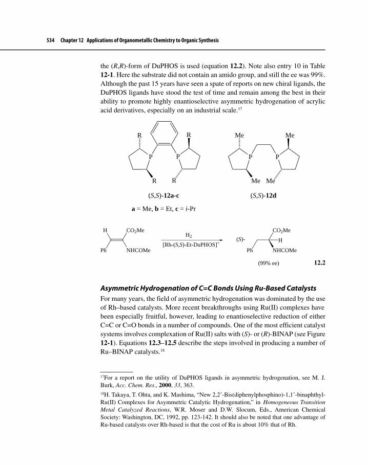
534 Chapter 12 Applications of Organometallic Chemistry to Organic Synthesis
the (R,R)-form of DuPHOS is used (equation 12.2). Note also entry 10 in Table 12-1. Here the substrate did not contain an amido group, and still the ee was 99%. Although the past 15 years have seen a spate of reports on new chiral ligands, the DuPHOS ligands have stood the test of time and remain among the best in their ability to promote highly enantioselective asymmetric hydrogenation of acrylic acid derivatives, especially on an industrial scale.17
P P
R
R
R
R
P P
Me
Me
Me
Me
(S,S)-12a-c (S,S)-12d
a = Me, b = Et, c = i-Pr
CO2Me
NHCOMePh
H
[Rh-(S,S)-Et-DuPHOS]+
H2
Ph
CO2Me
NHCOMe
H(S)-
(99% ee)
12.2
Asymmetric Hydrogenation of C=C Bonds Using Ru-Based CatalystsFor many years, the field of asymmetric hydrogenation was dominated by the use of Rh–based catalysts. More recent breakthroughs using Ru(II) complexes have been especially fruitful, however, leading to enantioselective reduction of either C=C or C=O bonds in a number of compounds. One of the most efficient catalyst systems involves complexation of Ru(II) salts with (S)- or (R)-BINAP (see Figure 12-1). Equations 12.3–12.5 describe the steps involved in producing a number of Ru–BINAP catalysts.18
17For a report on the utility of DuPHOS ligands in asymmetric hydrogenation, see M. J. Burk, Acc. Chem. Res., 2000, 33, 363.18H. Takaya, T. Ohta, and K. Mashima, “New 2,2�-Bis(diphenylphosphino)-1,1�-binaphthyl-Ru(II) Complexes for Asymmetric Catalytic Hydrogenation,” in Homogeneous Transition Metal Catalyzed Reactions, W.R. Moser and D.W. Slocum, Eds., American Chemical Society: Washington, DC, 1992, pp. 123-142. It should also be noted that one advantage of Ru-based catalysts over Rh-based is that the cost of Ru is about 10% that of Rh.

12-1 Enantioselective Functional Group Interconversions 535
[RuCl2(COD)]n + (S)-BINAPEt3N
PhCH3Ru2Cl4[(S)-BINAP]2 NEt3
(Ru-(S)-BINAP) 12.3
Ru-(S)-BINAPRCO2
− Na+
t-BuOH
Ph2P
PPh2
Ru
O
O
R
O
R
O
12.4
Ph2P
PPh2
RuX
X−RuX2
2
(S)-BINAP
1) RuX3-nH2O EtOH/H2O
2) KX/EtOH H2O
X = Cl, Br, I
12.5
We encountered Rh–BINAP as a hydrogenation catalyst earlier in Chapter 12 (Table 12-1) and as a catalyst for double bond isomerization in Section 9-7-3. As the examples below will show, Ru–BINAP catalysts are indeed even more versatile and selective than corresponding Rh complexes. In general, like Rh(I) catalysts, Ru(II) catalysts usually must have a chelating heteroatom (O or N) positioned close to the C=C bond undergoing saturation for effective stereose-lection to occur. Equation 12.6 shows an early example of the work of Noyori,19 who pioneered in the development of Ru(II) hydrogenation catalysts, showing enantioselective hydrogenation of an amidocinnamate ester.20
PhCO2Me
NHCOMe
[(R)-BINAP]Ru(OAc)2
H2
MeOHPh
CO2Me
NHCOMe
H(R)-
92% ee
The mechanism of asymmetric C=C hydrogenation, shown in Scheme 12.4, probably involves the formation of a Ru−H species 13 (see also Scheme 9.8
19R. Noyori shared the Nobel Prize in Chemistry in 2001 with W. S. Knowles, who pioneered the use of Rh-catalyzed asymmetric hydrogenation, and K. B. Sharpless, who is known for fundamental work on asymmetric epoxidation and dihydroxylation of alkenes involving transition metal catalysis.20T. Ohta, H. Takaya, and R. Noyori, Inorg. Chem., 1988, 27, 566 and M. Kitamura, M. Tokunaga, and R. Noyori, J. Org. Chem., 1992, 57, 4053.
12.6

536 Chapter 12 Applications of Organometallic Chemistry to Organic Synthesis
for non-asymmetic hydrogenation by the monohydride mechanism), which contrasts with the dihydride mechanism that is prevalent with hydrogenation by cationic Rh(I) complexes. The carbonyl oxygen atom also coordinates to the Ru.
The stereochemistry of the stereogenic center is fixed in going from structure 15 to 13. It appears that, unlike the case with Rh-catalysis, the stereochemistry of the major product corresponds to the higher stability of one of the diastereo-meric complexes 14 compared with 14′. The relative stability of 14 results from lack of steric interactions between the CO2Me group at the α-position and one of the phenyl groups attached to P, and this diastereomer goes on smoothly to give the (R)-dihydrocinnamate.21 In general, Ru–(R)-BINAP catalyzes formation of (R)-hydrogenated product and Ru–(S)-BINAP gives (S)-product, which is oppo-site to the results for Rh–BINAP hydrogenation catalsyts.
21See Footnote 14.
Scheme 12.4 Mechanism of Asymmetric Hydrogenation of C=C Bonds
(P−P)Ru(OAc)2
HOAc
H2
RuP
POAc
H
(P−P)Ru(H)(OAc)
RuP
POAc
H2
Ph
CO2MeMeCONHH
MeO2C NHCOMe
Ph
P−P = (R)-BINAP
R
13
1415
RuP
POAc
H
CO2Me
NH
MeO
Ph
14'
Me
NH
O
CO2MePhPh
NH
OMe
CO2Me
+
Major
Minor
α
β

12-1 Enantioselective Functional Group Interconversions 537
Allylic and homoallylic22 alcohols undergo asymmetric hydrogenation (Scheme 12.5).23 The Ru(O2C−CF3)2–BINAP catalyst (equation 12.4) used in these reactions is extremely specific in many respects. Both enantiomers of citronellol result with high % ee starting with either geraniol or nerol, depend-ing on whether (S)- or (R)-BINAP is the ligand. The reaction shows double bond face selectivity, since the same catalyst, Ru–(S)-BINAP, transforms gera-niol into (R)-citronellol and nerol into (S)-citronellol. Note that the remote double bond is unreactive to the hydrogenation conditions, indicating that the allylic alcohol group probably provides necessary secondary chelation during the reaction. Further demonstration of this chelation is also shown in Scheme 12.5, whereby homogeraniol reacts to give (R)-homocitronellol. Extending the carbon chain by just one more carbon, however, results in no reaction because the OH group is too far removed from the C=C double bond to effectively also bind to Ru.
22Homoallylic systems have one more carbon atom than allylic systems. For example, CH2=CH-CH2- is allylic, whereas CH2=CH-CH2-CH2- is homoallylic.23H. Takaya, T. Ohta, N. Sayo, H. Kumobayashi, S. Akutagawa, S. Inoue, I. Kasahara, and R. Noyori, J. Am. Chem. Soc., 1987, 109, 1596.
Scheme 12.5 Ru(II)–BINAP-Catalyzed Hydrogenation of Allylic and Homoallylic Alcohols
OH
H2
Ru-(S)-BINAP OH
Me H
H2/Ru-(R)-BINAP
OH
H Me
OH
Geraniol
Nerol
(R)-Citronellol(96% ee from geraniol
98% ee from nerol)
(S)-Citronellol(93% ee from geraniol
98% ee from nerol)
H2
Ru-(S)-BINAP
Homogeraniol
OHH2
Ru-(S)-BINAP
(R)-Homocitronellol(92% ee)
OH
Me H
H2
Ru-(S)-BINAPOHNo reaction
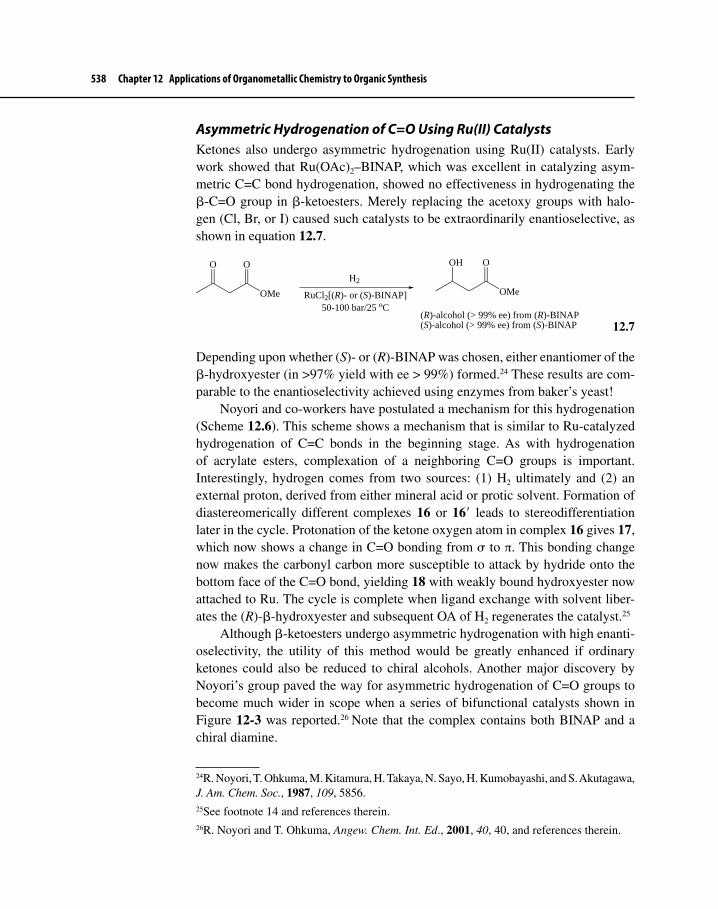
538 Chapter 12 Applications of Organometallic Chemistry to Organic Synthesis
Asymmetric Hydrogenation of C=O Using Ru(II) CatalystsKetones also undergo asymmetric hydrogenation using Ru(II) catalysts. Early work showed that Ru(OAc)2–BINAP, which was excellent in catalyzing asym-metric C=C bond hydrogenation, showed no effectiveness in hydrogenating the β-C=O group in β-ketoesters. Merely replacing the acetoxy groups with halo-gen (Cl, Br, or I) caused such catalysts to be extraordinarily enantioselective, as shown in equation 12.7.
OMe
O O
H2
RuCl2[(R)- or (S)-BINAP]50-100 bar/25 oC
OMe
OH O
(R)-alcohol (> 99% ee) from (R)-BINAP(S)-alcohol (> 99% ee) from (S)-BINAP
12.7
Depending upon whether (S)- or (R)-BINAP was chosen, either enantiomer of the β-hydroxyester (in >97% yield with ee > 99%) formed.24 These results are com-parable to the enantioselectivity achieved using enzymes from baker’s yeast!
Noyori and co-workers have postulated a mechanism for this hydrogenation (Scheme 12.6). This scheme shows a mechanism that is similar to Ru-catalyzed hydrogenation of C=C bonds in the beginning stage. As with hydrogenation of acrylate esters, complexation of a neighboring C=O groups is important. Interestingly, hydrogen comes from two sources: (1) H2 ultimately and (2) an external proton, derived from either mineral acid or protic solvent. Formation of diastereomerically different complexes 16 or 16′ leads to stereodifferentiation later in the cycle. Protonation of the ketone oxygen atom in complex 16 gives 17, which now shows a change in C=O bonding from σ to π. This bonding change now makes the carbonyl carbon more susceptible to attack by hydride onto the bottom face of the C=O bond, yielding 18 with weakly bound hydroxyester now attached to Ru. The cycle is complete when ligand exchange with solvent liber-ates the (R)-β-hydroxyester and subsequent OA of H2 regenerates the catalyst.25
Although β-ketoesters undergo asymmetric hydrogenation with high enanti-oselectivity, the utility of this method would be greatly enhanced if ordinary ketones could also be reduced to chiral alcohols. Another major discovery by Noyori’s group paved the way for asymmetric hydrogenation of C=O groups to become much wider in scope when a series of bifunctional catalysts shown in Figure 12-3 was reported.26 Note that the complex contains both BINAP and a chiral diamine.
24R. Noyori, T. Ohkuma, M. Kitamura, H. Takaya, N. Sayo, H. Kumobayashi, and S. Akutagawa, J. Am. Chem. Soc., 1987, 109, 5856.25See footnote 14 and references therein.26R. Noyori and T. Ohkuma, Angew. Chem. Int. Ed., 2001, 40, 40, and references therein.

12-1 Enantioselective Functional Group Interconversions 539
Equations 12.8, 12.9, and 12.10 demonstrate the range of ketones that undergo asymmetric hydrogenantion using bifunctional catalysts.27
CH3
O
KO-t-Bu/i-PrOH
H2/Ru-[(S)-XylBINAP][(S)-DAIPEN]
CH3
OH
H
(96% yield; 95% ee)
(R)-
12.8
Me
O
KO-t-Bu/i-PrOH
H2/Ru-[(S)-XylBINAP][(S)-DAIPEN] Me
OHH
(R)-
(99% yield; 100% ee)
12.9
27T. Ohkuma, M. Koizumi, H. Doucet, T. Pham, M. Kozawa, K. Murata, E. Katayama, T. Yokozawa, T. Ikariya, and R. Noyori, J. Am. Chem. Soc., 1998, 120, 13529.
Scheme 12.6 Mechanism of Asymmetric Hydrogenation of β-Ketoesters
(P−P)RuCl2(S)2
HCl
H2
RuP
PCl
H
(P−P)RuHCl(S)2
H2
P−P = (R)-BINAP16
16'
OMeO
OMe
+
Major
Minor
S = protic solvent
OMe
Me
O
O
2 S
RuP
PCl
H
MeO
OOMe
RuP
PCl
H
OMeO
O MeH
RuP
P SCl
SS
H+/S
S
RuP
PCl OMe
O
O MeH
H
OMe
Me
HO
O
R
HA
A−
A−
A−
Hydride transfer
17
18

540 Chapter 12 Applications of Organometallic Chemistry to Organic Synthesis
Me
O
KO-t-Bu/i-PrOH
H2/Ru-[(R)-XylBINAP][(R,R)-DPEN] Me
HHO
(S)-
(100% yield; 96% ee)
F F
12.10
Equation 12.9 exemplifies excellent chemoselectivity, whereby a C=C bond conjugated with a C=O bond does not undergo hydrogenation under these condi-tions. There is a good reason for this effect. When bifunctional catalysts are used to hydrogenate the C=O bond, the mechanism of C=O hydrogenation is differ-ent than that we have seen earlier using monofunctional catalysts. Scheme 12.7 shows a catalytic cycle for C=O hydrogenation in which two H atoms are trans-ferred to the C=O group by an “outer sphere” mechanism that takes place through a six-membered ring transition state during step d, a mechanism termed “non-classical” by Noyori. The diamine ligand can donate a proton to the carbonyl oxygen while a hydride ligand attaches to one or the other face of the carbonyl
Figure 12-3 Ru(II)–BINAP/Diamine Catalysts
RuP
PH2N
NH2
Cl
ClAr
Ar
Ar
ArR2
R1
R3
H
Ru(II)-diphosphine-diamine catalyst
Diphosphines:
(S)-BINAP (Ar = Ph)
(S)-TolBINAP (Ar = 4-MePh)
(S)-XylBINAP (Ar = 3,5-(Me)2Ph)
(S,S)-DIOP
(S,S)-CHIRAPHOS
Diamines:
Ph
Ph
H2N
H2N
H2N
H2N
H2N
H2N
OMe
OMe
H
(S,S)-DPEN (S,S)-Cyclohexane-1,2-diamine
(S)-DAIPEN

12-1 Enantioselective Functional Group Interconversions 541
Scheme 12.7 Mechanism for Asymmetric Hydrogenation of C=O Bonds in the Presence of Bifunctional Ru(II) Catalysts
RuP
PH2N
NH2
Cl
Cl
H2
HCl + Cl−
RuP
PH2N
NH2
H
RuP
PH2N
NH2
H
H H
RuP
P N
NH2
H
H
RuP
P N
NH2
H
H2
H+
H2
H+
H H
H
C O
C O
HH
RuP
P N
NH2
H
H
HH
C O
a
b
cd
e
("Non-classical" transition state for step d)
Groups normally attached to the diphosphine anddiamine are not shown in order to enhance clarity.
group at carbon. At no time is binding of the C=O bond to the Ru required during hydrogenation, yet stereoselectivity is governed by the asymmetric bias of both the BINAP and the diamine.28
28Previous catalytic pathways for hydrogenation have involved transfer of a metal-bound hydride to the substrate containing the double bond, which is also bonded to the metal. This

542 Chapter 12 Applications of Organometallic Chemistry to Organic Synthesis
Hydrogenation is an excellent example of green chemistry. Atom economy is high because the addition of H2 across a multiple bond yields only one con-stitutional isomer. Under conditions of asymmetric catalysis, one enantiomer is strongly preferred, so little material is wasted in separation procedures (resulting in a low E-factor). Often, such reactions are also carried out under mild condi-tions involving low temperature and pressure, which means that energy consump-tion is minimized. Recent research has shown that water, the premier example of an environmentally benign solvent, can serve as a reaction medium for asymmet-ric hydrogenation of ketones under conditions of transfer hydrogenation (TH or ATH when the hydrogenation is asymmetric).
TH is an indirect form of hydrogenation that can be catalyzed by transition metal complexes.29 Equation 12.11 outlines the concept where 2-propanol is the hydrogen transfer agent, which means that H2 does not have to be pres-ent. Two hydrogens are transferred from 2-propanol, and the by-product is acetone.
R1
C
R2
O[Ru−H]
C O
HHMe
Me Me
C
Me
O
R1
C
R2
O
HH
12.11
Another source of hydrogen is formate ion, HCOO–, which can donate its hydrogen atom to a substrate, forming CO2 as a by-product. Xiao has shown that acetophe-none can undergo ATH with nearly quantitative conversion when it is converted to the corresponding (R)-alcohol in 95% ee (equation 12.12).30 The reaction only takes one hour when it is run at 40o C in aqueous formate solution using a chiral η6–arene–Ru catalyst with a modified DPEN ligand, mild conditions indeed. The most likely mechanism involves transfer of two hydrogen atoms to the ketone via a transition state that was already shown in Scheme 12.7.
is called an “inner-sphere” mechanism. For more details on this non-classical hydrogenation, see Footnote 26.29For a recent review on transfer hydrogenation involving Ru complexes, see S. E. Clapham, A. Hadzovic, and R. H. Morris, Coord. Chem. Rev., 2004, 248, 2201.30(a) X. F. Wu, X. G. Li, W. Hems, F. King, and J. Xiao, Org. Biomol. Chem., 2004, 2, 1818; and (b) X. G. Li, X. F. Wu, W. P. Chen, F. E. Hancock, F. King, and J. Xiao, Org. Lett., 2004, 6, 3321.

12-1 Enantioselective Functional Group Interconversions 543
Me
O
HCO2−/H2O/40 oC
[L*2Ru−Cl] Me
H OH
(R)-
RuCl N
H2
N
TsPh
Ph
(R,R)-TsDPEN
(99% conversion; 95% ee)
[L*2Ru−Cl]:
12.12
Other alkyl aryl ketones show similar results with this catalyst. Because the cata-lyst is mostly water insoluble, it is possible that catalysis occurs on water rather than in water.
Even Rh(I) and Ir(I) complexes of diamines similar to that shown in equa-tion 12.12 are very effective catalysts for ATH of C=O groups. At present, how-ever, the scope of the reaction is limited to aryl ketones and imines. Nevertheless, the potential for the success or ATH under green chemistry conditions remains strong.31
Asymmetric Hydrogenation Using Cationic Ir(I) CatalystsIn Section 9-4-3, we mentioned that cationic Ir catalysts (sometimes called Crabtree catalysts) are quite active for hydrogenation of highly substituted C=C bonds. Moreover, asymmetric Ir-catalyzed hydrogenation of an imine is a key step in the industrial-scale synthesis of the herbicide (S)-metolachlor (Section 9-7-2). In addition to these applications, relatively recent work has shown that cationic Ir(I) complexes bonded to chiral ligands can catalyze asymmetric hydrogenation of unfunctionalized C=C bonds (i.e., C=C bonds to which no polar functional groups, such as C=O, are attached).
Largely through efforts of Pfaltz and co-workers, a series of chiral ligands was developed that allowed unfunctionalized alkenes to undergo asymmetric hydrogenation;32 structures 19 (tBuPHOX ligand), 20, and 21 show a few of these.
31For a recent summary of ATM in green solvents, see X. Wu and J. Xiao, Chem. Comm., 2007, 2449.32For recent reviews of this work, see (a) S. J. Roseblade and A. Pfaltz, C. R. Chemie, 2007, 10, 178 and (b) K. Källström, I. Munslow, and P. G. Andersson, Chem. Eur. J., 2006, 12, 3194.
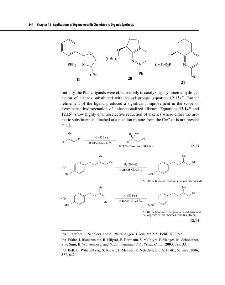
544 Chapter 12 Applications of Organometallic Chemistry to Organic Synthesis
N
O
PPh2
t-Bu19
N
Ph
O
(t-Bu)2P
20
N
O
(o-Tol)2P
Ph21
Initially, the Pfaltz ligands were effective only in catalyzing asymmetric hydroge-nation of alkenes substituted with phenyl groups (equation 12.13).33 Further refinement of the ligand produced a significant improvement in the scope of asymmetric hydrogenation of unfunctionalized alkenes. Equations 12.1434 and 12.1535 show highly enantioselective reduction of alkenes where either the aro-matic substituent is attached at a position remote from the C=C or is not present at all.
Me
PhPh
H2 (50 bar)
Ir-19/CH2Cl2/23 oC
Me
PhPh
H
(> 99% conversion; 98% ee)
12.13
Me
Me
MeO
(E)-H2 (50 bar)
Ir-21/CH2Cl2/23 oC
Me
Me
MeO
*
*: 93% ee (absolute configuration not determined)
Me
MeO
(Z)-H2 (50 bar)
Ir-21/CH2Cl2/23 oC
Me
Me
MeO
*
*: 98% ee (absolute configuration not determinedbut opposite to that obtained from (E)-alkene)
Me
12.14
33A. Lightfoot, P. Schnider, and A. Pfaltz, Angew. Chem. Int. Ed., 1998, 37, 2897.34A. Pfaltz, J. Blankenstein, R. Hilgraf, E. Hörmann, S. McIntyre, F. Menges, M. Schönleber, S. P. Smit, B. Würstenberg, and N. Zimmermann, Adv. Synth. Catal., 2003, 345, 33.35S. Bell, B. Würstenberg, S. Kaiser, F. Menges, T. Netscher, and A. Pfaltz, Science, 2006, 311, 642.

12-1 Enantioselective Functional Group Interconversions 545
MeH2 (50 bar)
Ir-20/CH2Cl2/23 oC
*: 92% ee (absolute configuration not determined)
Me
Me
Me
*
12.15
One proposal for the catalytic cycle involves an Ir(III)–dihydride intermedi-ate that forms after OA of H2 onto an Ir(I)–alkene complex. Experimental results seem to support this cycle,36 but computational studies suggest that the cycle involves Ir(III) and Ir(V) intermediates.37 The details of neither proposal have been elucidated. Work continues to expand the scope of this reaction to include asymmetric hydrogenation of any unfunctionalized alkene that could yield a chiral alkane.
12-1-2 Asymmetric OxidationsOne of the most exciting developments in asymmetric catalysis over the past 25 years has been the discovery of transition metal complexes that catalyze the oxi-dation of alkenes to chiral epoxides and 1,2-diols. Equations 12.16, 12.17, and 12.18 show examples of epoxidation and 1,2-dihydroxylation.
CH2OH (+)-Diisopropyl tartrate
Ti(O-i-Pr)4/t-BuOOHCH2OH
O
H
H
(80% yield; 95% ee)
12.16
36R. Dietiker and P. Chen, Angew. Chem. Int. Ed., 2004, 43, 5513.37Y. Fan, X. Cui, K. Burgess, and M. B. Hall, J. Am. Chem. Soc., 2004, 126, 16688 and P. Brandt, C. Hedberg, and P. G. Andersson, Chem. Eur. J., 2003, 9, 339.
Propose a catalytic cycle for Ir-catalyzed asymmetric hydrogenation that involves Ir(I) and Ir(III) complexes as intermediates. Assume that the starting point of the cycle is a cationic Ir(I) complex, which is bonded to a general aminophosphine ligand and solvent molecules as needed to form a square planar complex. OA of H2 is then followed by ligand displacement of solvent by alkene. Which step introduces a stereogenic center?
Exercise 12-3

546 Chapter 12 Applications of Organometallic Chemistry to Organic Synthesis
OMe
Me NaOCl
Mn-salen/CH2Cl2/4 oCNC
OMe
Me
NCO
(96% yield; 97% ee)
OMn
N
O
N
ClR R
An example of a Mn-salen ligand (R = alkyl):
12.17
PhCO2Et
K3Fe(CN)6/OsO4 (cat.)
Dihydroquinine (cat.)
PhCO2Et
OH
OH
(95% ee)
12.18
Equation 12.16 is an example of the Sharpless–Katsuki asymmetric epoxi-dation of allylic alcohols, which is catalyzed by a Ti complex bound to a chiral tartrate ligand.38 A Mn–salen39 complex serves as catalyst for asymmetric epoxi-dation (Jacobsen–Katsuki reaction) of a wide variety of unfunctionalized alkenes, shown in equation 12.17.40 OsO4 complexed with chiral alkaloids, such as qui-nine derivatives (equation 12.18), catalyzes asymmetric 1,2-dihydroxylation of alkenes (known as the Sharpless asymmetric dihydroxylation).41 The key step of all these transformations is the transfer of metal-bound oxygen, either as a single atom or as a pair, to one face of the alkene.
It should be pointed out, however, that these heteroatom transfer reactions do not typically involve true organometallic complexes; traditional carbon-based
38T. Katsuki and K. B. Sharpless, J. Am. Chem. Soc., 1980, 102, 5974 and B. E. Rossiter, T. Katsuki, and K. B. Sharpless, J. Am. Chem. Soc., 1981, 103, 464; for a comprehensive review of the reaction, see T. Katsuki and V. S. Martin, Org. React., 1996, 48, 1; for the Sharpless Nobel Prize in Chemistry (2001) lecture, see K. B. Sharpless, Angew. Chem. Int. Ed., 2002, 41, 2024.39Salen is an abbreviation for the name of a ligand composed of salicylic acid (sal) and ethylenediamine (en).40W. Zhang, J. L. Loebach, S. R. Wilson, and E. N. Jacobsen, J. Am. Chem. Soc., 1990, 112, 2801; E. N. Jacobsen, W. Zhang, A. R. Muci, J. R. Ecker; and L. Deng, J. Am. Chem. Soc., 1991, 113, 7063; T. P. Yoon and E. N. Jacobsen, Science, 2003, 299, 1691; and R. Irie, K. Noda, Y. Ito, and T. Katsuki, Tetrahedron Lett., 1991, 32, 1055.41E. N. Jacobsen, I. Marko, W. S. Mungall, G. Schroeder, and K. B. Sharpless, J. Am. Chem. Soc., 1988, 110, 1968 and H. C. Kolb, M. S. VanNieuwenhze, and K. B. Sharpless, Chem. Rev., 1994, 94, 2483.

12-1 Enantioselective Functional Group Interconversions 547
ligands (e.g., CO, alkenes, and Cp, or other ligands considered “organometallic,” such as hydride or PR3), are not bound to the metal during the catalytic cycle. Despite the high significance of these reactions to the field of organic synthe-sis, we will limit our discussion of asymmetric oxidation to reactions in which traditional organometallic complexes are involved during catalysis.42
Pd-Catalyzed Oxidation of Secondary AlcoholsOver the past 10 years, there have been great strides reported in the Pd-catalyzed oxidation of secondary alcohols to ketones using O2 as the ultimate oxidizing agent. Often, these reactions exhibit many of the tenets of green chemistry by occurring under very mild conditions, even using air instead of pure O2. Reactions 12.1943 and 12.2044 reveal typical conditions for such reactions, which were developed by Uemara and Sheldon almost simultaneously. Primary alcohols also react to give aldehydes, but lower yields and overoxidation are problems. Recently reported work by Sigman has shown, by replacing pyridine with triethylamine, that a wide range of secondary and primary alcohols can be oxidized to ketones and aldehydes in very high yield using O2 or even air as the ultimate oxidant.45 These reactions seem general enough to obviate the use of carcinogenic and environmentally hazardous Cr(VI) reagents, which have been used traditionally for alcohol oxidations.
t-Bu OHO2 (1 bar)
Pyridine/PhMeMol. sieves/80 oC
Pd(OAc)2 (5 mol%)
t-Bu O
(93% yield)
12.19
OH
Air (30 bar)
H2O/DMSO/100 oC
N
N
Me
Me
Pd(OAc)2
(0.5 mol%)
O
(90% conversion)
12.20
42The references cited above should point readers to current work in the chemical literature that is associated with asymmetric heteroatom transfer oxidations. 43For a review of Uemura’s work, see T. Nishimura and S. Uemura, Synlett, 2004, 2, 201.44For a review of green oxidations by Sheldon’s group, see G.-J. ten Brink, I. W. C. E. Arends, M. Hoogenraad, G. Verspui, and R. Sheldon, Adv. Synth. Catal., 2003, 345, 1341.45M. J. Schultz, S. S. Hamilton, D. R. Jensen, and M. S. Sigman, J. Org. Chem., 2005, 70, 3343.

548 Chapter 12 Applications of Organometallic Chemistry to Organic Synthesis
Over the last several years, Stoltz and Sigman simultaneously reported on the potential of using asymmetric versions of such oxidations to selectively oxi-dize racemic secondary alcohols so that one enantiomer undergoes conversion to the corresponding ketone and the other remains unreacted. This process, called a kinetic resolution, allows isolation of one enantiomer in up to 50% yield,46 and it mimics enzyme-catalyzed resolution (whereby the enzyme interacts with only one enantiomer). It is thus typically more efficient than chemical resolution pro-cesses that form diastereomeric derivatives of each enantiomer, which then must be laboriously separated and purified. The method also is often superior to sepa-ration on chiral chromatography columns, which is usually amenable to use only on a small scale. If the unreacted enantiomer is the one desired, the technique is even more attractive when there is a way of recycling the ketone product back to racemic alcohol and then oxidizing this material. Yields higher than 50% can then be realized.
To incorporate a chiral environment into the oxidation, both Stoltz and Sigman employed (−)-sparteine (22a) as a bidentate ligand to replace pyri-dine, which was used for the achiral versions of alcohol oxidation mentioned above.
46Stoltz terms such reactions stereoablative. Ablation is the effect of taking something away. For example, the heat shield of the Space Shuttle burns away (ablates) sacrificially during reentry after a mission in order to preserve the spacecraft. An ablative reaction is one where an existing stereogenic element in a molecule is eliminated. For more information on abla-tive reactions, see J. T. Mohr, D. C. Ebner, and B. M. Stoltz, Org. Biomol. Chem., 2007, 5, 3571.
Exercise 12-4 Consider Stoltz’s stereoablative kinetic resolution of a naphthylic secondary alcohol shown in the following equation.
OH
(�)-O2 (1 bar)
PdL2Cl2/L*2
PhMe/80 oC
L*2: (−)-sparteine, a chiral diamine
O OH
+
(99% ee)
Suggest a means for recycling the unreacted ketone back to racemic alcohol so that overall yield of the desired (S)-alcohol is greater than 50% (see Footnote 46).

12-1 Enantioselective Functional Group Interconversions 549
NN
22a: (−)-Sparteine
NN
22b: (−)-α-Isosparteine
Careful work on the mechanism of Pd-(−)-sparteine oxidation has pinned down most of the details of the process, resulting in the catalytic cycle shown in Scheme 12.8.47
The rate-determining step occurs during β-hydride elimination. One model for enantioselection is shown in Figure 12-4, where the diamine ligand, (−)-spar-teine, exhibits C1 symmetry48 instead of C2. C2 symmetry is associated with dia-stereomeric structure 22b, (−)-α-isosparteine). C2 is also the inherent symmetry of chiral bisphosphine ligands used for asymmetric hydrogenation.49
In this model, only one enantiomer of the racemic alcohol yields a complex that is readily suitable for β-elimination, whereas the diastereomerically related complex, with the other enantiomer bonded to Pd, is energetically unfavorable. An energetically unsuitable complex (23a) is shown by the interference of the larger group GL, attached to C-1 of the alcohol, interfering with sterically encum-bered quadrant III of the (−)-sparteine ligand. The energetically more favorable diastereomeric complex (23b) shows the smaller group, GS, pointing to quad-rant III and GL filling the void denoted in Figure 12-4 as quadrant IV. It is this complex that is set up favorably for β-elimination to form the corresponding ketone. The energetically unsuitable complex breaks apart under the reaction conditions and releases unreacted, but enantiomerically pure, alcohol. Table 12-2 (on p. 552) shows the range and enantioselectivity of this oxidation.
There are challenges that remain for optimization of the Pd-(−)-sparteine-catalyzed asymmetric oxidation of secondary alcohols—including accelerating the relatively slow reaction rate, finding a general method for recycling oxidized product, and using air rather than O2 as oxidant in all cases. Nonetheless, this
47R. J. Nielsen, J. M. Keith, B. M. Stoltz, and W. A. Goddard, III, J. Am. Chem. Soc., 2004, 126, 7967 and M. J. Schultz, R. S. Adler, W. Zierkiewicz, T. Primolov, and M. S. Sigman, J. Am. Chem. Soc., 2005, 127, 8499.48Meaning that there are no elements of symmetry present except rotation about an axis by 360o.49R. Trend and B. M. Stoltz, J. Am. Chem. Soc., 2004, 126, 4482; see also J. A. Mueller, A. Cowell, B. D. Chandler, and M. S. Sigman, J. Am. Chem. Soc., 2005, 127, 14817 for additional work on the origin of enantioselectivity.

550 Chapter 12 Applications of Organometallic Chemistry to Organic Synthesis
Scheme 12.8 Catalytic Cycle for Pd-(−)-Sparteine Asymmetric Oxidation of Secondary Alcohols
PdX2(NBD)
(−)-L2
NBD
PdX
N N
X
(−)-L2 = N N = (−)-Sparteine
X = Cl or OAc
B = (−)-Sparteine or Cs2CO3
NBD = Norbornadiene
PdX
N N
XO
C H
Me
Ph
H
PdO
N N
X
CH
Ph
Me
B
BH+ X−
PdO
N N
H
CPh Me
X−
O
CPh Me
β-Elimination
PdN N
HX
PdN N
Pd(0)
Pd(II)
2 HX + 1/2 O2
H2O
PhCH(OH)CH3
HX
RE
method has promise as a means of kinetic resolution of secondary alcohols with enantioselectivities approaching those achieved using enzymes.
Oxidative CyclizationsAs we saw in Chapter 9 (Section 9-3), the Wacker Chemie process converts eth-ene to ethanal under Pd(II) catalysis. This process has potential in the realm of organic synthesis as a general means of converting alkenes to aldehydes or ketones. Since the original discovery of the Wacker Chemie process, there has been recent, renewed interest in making the process simpler and greener by using only O2 as the ultimate and sole oxidizing agent. Recall that the origi-nal Wacker process required the use of stoichiometric amounts of Cu(II), which served to oxidize Pd(0) back to Pd(II) in a connected, separate cycle. The use of

12-1 Enantioselective Functional Group Interconversions 551
Figure 12-4 A Predictive Model for Enantioselection in Asymmetric Oxidation of Secondary Alcohols
NNNN
22a: (−)-Sparteine 22b: (−)-α-Isosparteine
N N
Bottom view
N N
IIV
III II
IIV
III II
Bottom view
Bottom view translated into quadrants: shaded areas depict the steric bulk of the carbonframework of (−)-sparteine or (−)-α-isosparteine; unshaded areas indicate the lack of steric hindrance.
Side view Side view
N N
PdClO
C1 HGL
GS
N N
PdClO
C1 HGS
GL
23a 23b
(−)-Sparteine interactions: (−)-α-Isosparteine interactions:
O2 as the sole oxidant would obviate the use of relatively expensive Cu(II) as a co-oxidant and would be consistent with the tenets of green chemistry, especially if air instead of pure O2 were employed.
Kaneda recently reported a major step toward this goal, which involved run-ning the oxidation using O2 at a pressure of 6 bar and at a temperature 80 oC in dimethylacetamide(DMA)–H2O solvent (equation 12.21).50
50T. Mitsudome, T. Umetani, N. Nosaka, K. Mori, T. Mizugaki, K. Ebitani, and K. Kaneda, Angew. Chem. Int. Ed., 2006, 45, 481.
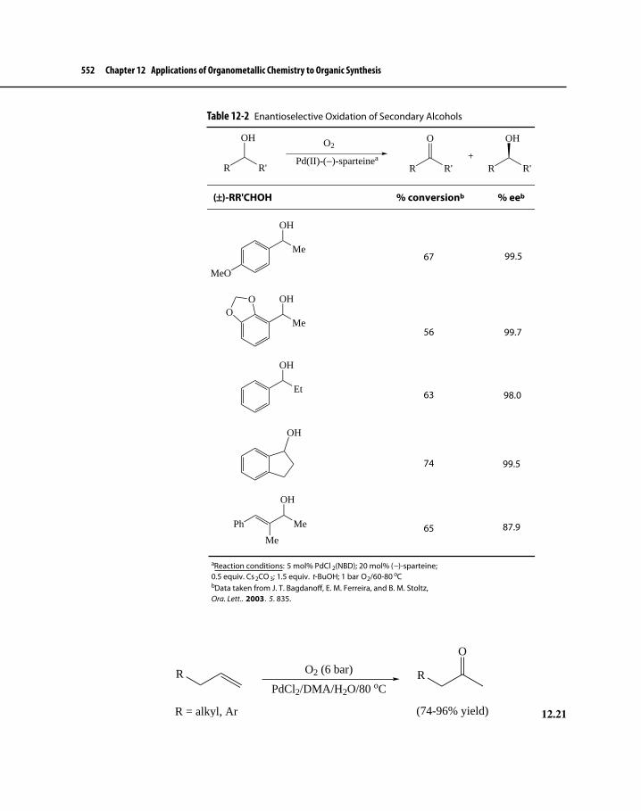
552 Chapter 12 Applications of Organometallic Chemistry to Organic Synthesis
O2 (6 bar)
PdCl2/DMA/H2O/80 oCR
R = alkyl, Ar
R
O
(74-96% yield) 12.21
Table 12-2 Enantioselective Oxidation of Secondary Alcohols
(±±)-RR'CHOH
R R'
OH
R R'
O
R R'
OH
+Pd(II)-(−)-sparteinea
O2
MeO
Me
OH
Me
OHOO
Et
OH
Ph Me
Me
OH
OH
67 99.5
56 99.7
63 98.0
74 99.5
65 87.9
aReaction conditions: 5 mol% PdCl 2(NBD); 20 mol% (−)-sparteine;0.5 equiv. Cs 2CO 3; 1.5 equiv. t-BuOH; 1 bar O2/60-80 oCbData taken from J. T. BagdanoI, E. M. Ferreira, and B. M. Stoltz,Org. Lett., 2003 , 5, 835.
% conversionb % eeb

12-1 Enantioselective Functional Group Interconversions 553
A wide range of terminal alkenes were converted to methyl ketones in 70–90% yield under the same reaction conditions. Shortly after Kaneda published his results, Sigman reported that using a PdCl2((−)-sparteine) as catalyst allowed the reaction to occur, albeit more slowly, under a balloon of O2 at 70 oC, also in DMA–H2O.51
A variation on Kaneda’s Wacker oxidation of terminal alkenes involves oxidative cyclization, shown generally in equation 12.22. Although this pro-cess does not show conversion of an alkene to a ketone, a formal oxidation occurs because there is a net loss of two hydrogen atoms in going to the cyclic ether.
OH
O2 (6 bar)
PdCl2/DMA/H2O/80 oCO
Me
(95% yield)
12.22
Presumably the reaction is Wacker-like because the tethered OH group must act as a nucleophile to attack the alkene group attached to Pd, which is analogous to H2O or Pd-bound OH attacking the ethene in the Wacker process. Recently, Stoltz and co-workers52 developed an elegant, mild Pd(II)-catalyzed cyclization process involving both cyclooxygenation and cycloamination under 1 bar of O2 at 80 oC in anhydrous toluene. Equation 12.23 outlines the scope of the reaction, and Scheme 12.9 shows a plausible mechanism for cyclization, along with an additional cycle designed to covert Pd(0) back to Pd(II) (see also Scheme 12.8). The details of the second cycle were elaborated on by Stahl53 for a similar Pd-catalyzed oxida-tion involving O2 as the sole oxidant. Stoltz reported that the cyclooxygenations involved syn attack of the OH group (attached as an alkoxide ligand to Pd) onto the complexed alkene, which is reminiscent of a Wacker oxidation. For reasons that remain unclear, the cyclization involving carboxyl OH proceeded with anti attack onto the alkene.
51C. N. Cornell and M. S. Sigman, Org. Lett., 2006, 8, 4117; for a summary of the progress to date in developing Wacker oxidations where O2 is the sole oxidant, see C. N. Cornell and M. S. Sigman, Inorg. Chem., 2007, 46, 1903.52R. M. Trend, Y. K. Ramtohul, E. M. Ferreira, and B. M. Stoltz, Angew. Chem. Int. Ed., 2003, 42, 2892.53B. A. Steinhoff, S. R. Fix, and S. S. Stahl, J. Am. Chem. Soc., 2002, 124, 766; B. A. Steinhoff and S. S. Stahl, Org. Lett., 2002, 4, 4179; and S. S. Stahl, J. L. Thorman, R. C. Nelson, and M. A. Kozee, J. Am. Chem. Soc., 2001, 123, 7188.

554 Chapter 12 Applications of Organometallic Chemistry to Organic Synthesis
Scheme 12.9 Pd(II)-Catalyzed, Wacker-Type Oxidative Cyclizations Where O2 Is the Sole Oxidant
LnPdX2
OH
PdLnX
X−
O
PdLnX
H
O
PdLnX
H
LnPdHX
LnPd(0)
LnPdO
O
2 HX
H2O2
O2
H2O
HX
OH
B
BH+ X−
O
L = Pyridine, (−)-SparteineX = CF3CO2
− (TFA)B = L or OH−, CO3
2−
X−
R = C=O or CH2YH = NHTs, NHOBn, OH
R
Me
Y
(63-90% yield)
O2 (1bar)
Pd(TFA)2/PyridinePhMe (dry)/80 oC
RY
Me
12.23

12-2 Carbon–Carbon Bond Formation via Nucleophilic Attack on an η3–π Ligand: the Tsuji–Trost Reaction 555
The cyclizations reported by Stoltz typically produce a stereogenic center. Accordingly, he was able to develop an asymmetric version of this cyclization in the case where the OH group is phenolic.54 Equation 12.24 shows an example of this cyclization, again using (−)-sparteine to create a chiral environment during the cyclization process.
OH
MeOO2 (1 bar)
[(−)-sparteine]Pd(TFA)2
PhMe/80 oC/mol. sieves O
MeO
(64% yield; 88% ee)
12.24
Although this cyclization is not yet general, there is potential for expanding the scope of this reaction to other systems. At present, the details of asymmetric oxidations are not as well characterized as those of hydrogenation, but the range of synthetically useful possibilities for transition metal catalyzed oxidation is larger.
12-2 CARBON–CARBON BOND FORMATION VIA NUCLEOPHILIC ATTACK ON AN η3–π LIGAND: THE TSUJI–TROST REACTIONThe remainder of Chapter 12 will explore how organotransition metal complexes are particularly useful in promoting the formation of a C−C bond, which is the most important reaction in organic synthesis. In the course of this treatment, we will see how fundamental types of organometallic reactions are involved in C−C bond formation. Section 12-2 considers a particularly useful and widely applica-ble method of C−C bond creation that features nucleophilic attack by carbanions on η3-allyl ligands. Later sections will draw attention to (1) 1,1- and 1,2-migratory insertion; (2) a sequence of oxidative addition, transmetallation, and reductive elimination; and (3) a variety of multiple C−C bond formations that produce rings, all involving fundamental organometallic reaction types and occurring in one grand chemical step.
54R. M. Trend, Y. K. Ramtohul, and B. M. Stoltz, J. Am. Chem. Soc., 2005, 127, 17778.
The stereochemical course of Wacker-type cyclization, when the nucleophile OH comes from an alcohol or a phenol, is different than it is when the OH originates from a carboxylic acid. How does the OH group of a carboxyl group differ from that of a phenol or alcohol? Consider in your answer such factors as pKa, stereochemical constraints, and nucleophilicity.
Exercise 12-5

556 Chapter 12 Applications of Organometallic Chemistry to Organic Synthesis
12-2-1 General Considerations: Mechanism and Achiral ExamplesIn organic chemistry, allylic substrates are relatively reactive toward some nucleophiles, as shown in equation 12.25. The reaction suffers, however, from a number of disadvantages, including unpredictable stereochemistry, poor control of regiochemistry, and the possibility of carbon-skeleton rearrangements.
R XNuc:
R Nuc + (±)-R
Nuc
+ X:
Nuc: = OR−, SR−, PR3, halide ionsX = halide ions, OTs
12.25
In contrast, η3–π–allyl metal complexes—especially cationic ones—are more reactive toward a variety of nucleophiles, usually with predictable regio- and stereochemistry. Carbon nucleophiles, moreover, react with these complexes, forming the all-important C−C bond. Since its discovery over 40 years ago, this transformation, now termed the Tsuji–Trost reaction (see Section 8-2-2 for a brief introduction to the Tsuji–Trost reaction and some leading early references), has seen increasing use as a means of enantioselective synthesis of chiral molecules. Palladium is by far the metal of choice to bind to η3–allyl ligands, forming rela-tively stable (but not too stable for catalytic reactions) complexes that are poten-tially isolable but rarely isolated.55 Commonly used leaving groups are listed below on the basis of their relative reactivity.
Cl and Br > O(C=O)OR (carbonates) > O(C=O)R (esters)
Considerations of stereochemistry and regiochemistry resulting from com-plexation of the allylic system and subsequent attack by a nucleophile are of great importance to the utility of the Tsuji–Trost reaction in organic synthesis. Schemes 12.10a and b show two catalytic cycles for the Tsuji–Trost allyla-tion reaction that result in two different stereochemical outcomes depending on the basicity of the nucleophile.56 Allylation by unstabilized or “hard” nucleo-philes (pKa of the conjugate acid > 25—typically organometallic compounds of Mg, Li, and Zn) generally results in an overall inversion of configuration at the allylic site (Scheme 12.10a), whereas stabilized or “soft” nucleophiles (pKa of the conjugate acid < 25—typically stabilized enolate ions such as the one derived from diethylmalonate) react to give net retention of configuration (Scheme 12.10b).
55Other metals that bond to allylic substrates with subsequent, synthetically useful nucleo-philic attack include Mo, W, Fe, and especially Ni.56B. M. Trost and D. L. Van Vranken, Chem. Rev., 1996, 96, 395.

12-2 Carbon–Carbon Bond Formation via Nucleophilic Attack on an η3–π Ligand: the Tsuji–Trost Reaction 557
Schemes 12.10a and 12.10b Catalytic Cycles Showing the Stereochemistry Associated with the Tsuji–Trost Reaction
LnPd(0)
LnPd
R
X
LnPd
R X−
LnPd
R
Nuc
LnPd
R
a
b
cd
e
R X R Nuc
Nuc−Μ
M−X
LnPd
R
LnPd
R X−
LnPd
R
Nuc
Nuc
R Nuc
X
R X
Scheme 12-10a
Scheme 12-10b
Nuc−M
M−X
a
b c
d
The steps leading to net inversion follow after complexation of the π ligand (step a, Scheme 12.10a) and begin with OA (Section 7-2-2) of the allyl−X bond onto Pd (inversion of configuration, step b), which is followed by a transmeta-lation (retention of configuration via possibly a σ bond metathesis, step c) and then reductive elimination of the nucleophile and allyl ligands (retention of

558 Chapter 12 Applications of Organometallic Chemistry to Organic Synthesis
configuration, step d). Decomplexation (step e) involves retention of stereochemis-try, so overall the one inversion step sets the stereochemistry for the entire cycle.
With soft nucleophiles, steps a and b of Scheme 12.10b are the same as those in Scheme 12.10a. The crucial difference between the two pathways originates in the next steps. Soft nucleophiles attack the η3–allyl complex anti to the metal (step c, Scheme 12.10b), which results in another inversion of configuration. This is fol-lowed by decomplexation (step d), which occurs with retention of configuration. Overall, therefore, two inversions followed by retention result in a net retention of configuration. Equations 12.26 and 12.27 illustrate the stereochemistry attendant to the reaction of diastereomeric allylic acetates with malonate ion.57
AcO CO2Me
Na+ −CH(CO2Me)2
Pd(PPh3)4CO2Me
CO2Me
MeO2C
12.26
AcO CO2Me
Na+ −CH(CO2Me)2
Pd(PPh3)4CO2Me
CO2Me
MeO2C
12.27
Nucleophiles, especially those that are sterically bulky and soft, tend to attack at the less substituted terminal position of unsymmetrically substituted η3–allyl ligands. This tendency is enhanced if substituents at a terminal allylic position are also bulky. Unfortunately, this is not a “hard and fast rule” (see discussion in Section 8-2-2 on regiochemistry at the terminal positions of η3–allyl ligands when electron donating groups occupy one of the terminal positions), and the regiochemistry of attack is complicated by a phenomenon chemists have termed a memory effect. Sometimes leaving groups seem to be reluctant to depart before nucleophilic attack, so attack occurs predominantly at the position where the leaving group was originally attached, although this position is more sterically hindered. Equations 12.28 and 12.2958 show the typical preference for nucleo-philic attack at the less substituted allylic position, when either the nucleophile is a separate molecule or it is already tethered to the allylic substrate, whereas equa-tion 12.30 demonstrates a memory effect. Studies of memory effects as a function of leaving groups are ongoing.59
57B. M. Trost and T. R. Verhoeven, J. Org. Chem., 1976, 41, 3215.58Loss of the carbethoxy group and conversion of CN to COOH in the product leads ultimately to synthesis of chrysanthemic acid, derivatives of which serve as effective insecticides known as pyrethrins. J. P. Genet and F. Piau, J. Org. Chem., 1981, 46, 2414.59For a recent study of memory effects in Tsuji–Trost allylation reactions, see P. Fristrup, T. Jensen, J. Hoppe, and P.-O. Norrby, Chem. Eur. J., 2006, 12, 5352; for some experimental

12-2 Carbon–Carbon Bond Formation via Nucleophilic Attack on an η3–π Ligand: the Tsuji–Trost Reaction 559
OAcPh + NaCH(CO2Me)2[(η3–allyl)PdCl]2
THF/25 oC(R)-MeO-MOP
NucPh
(NaNuc)
Ph
Nuc
+
(79 : 21)OMe
PPh2
(R)-MeO-MOP 12.28
MeO2C
CNAcOPd(PPh3)4
MeO2C
CN
LnPd
H
Na+ H:− LnPd
MeO2C
CN
12.29
Ph+ NaCH(CO2Me)2
[(η3–allyl)PdCl]2
THF/25 oC(R)-MeO-MOP
NucPh
(NaNuc)
Ph
Nuc
+
(23 : 77)
OAc
12.30
12-2-2 Asymmetric Tsuji–Trost AllylationsIt was not long after the original work on the Trost–Tsuji reaction that asym-metric examples were reported.60 In recent years, numerous cases have appeared where this reaction was used to create chiral substituted allylic compounds in high % ee. Enhancement of chirality in allyl substrates is challenging because chem-istry on the allylic ligand occurs remotely from the chiral ligand also attached to the metal. There are several different points in the catalytic cycles depicted in Schemes 12.10a and b where asymmetric induction could occur.61 These scenar-ios include the following:
1. Enantiotopic faces of the alkene: initial selective complexation of one or the other prochiral faces of the π bond of the allyl group to Pd will lead to one or the other enantiomer of the product (step a, Scheme 12.10a or b).62
2. Enantiotopic leaving groups: enantioselective ionization of the allylic leaving group during OA of a meso allylic system will lead to one or the other enantiomer of the product (step b, Scheme 12.10a or b).
studies, see T. Hayashi, M. Kawatsura, Y. Uozumi, J. Am. Chem. Soc., 1998, 120, 1681.60For accounts of early efforts in asymmetric Tsuji–Trost reactions, see B. M. Trost and P. E. Strege, J. Am. Chem. Soc., 1977, 99, 1650 and G. Consiglio and R. M. Weymouth, Chem. Rev., 1989, 89, 257.61See Footnote 56.62See Footnote 95 in Chapter 11 for a brief discussion on prochiral faces of a π bond.

560 Chapter 12 Applications of Organometallic Chemistry to Organic Synthesis
3. Enantioface exchange in the η3–allyl complex: enantioselection occurs because only one of the two π faces of the η3–allyl ligand is presented to the attacking nucleophile (just prior to step c, Scheme 12.10a or b).
4. Attack at enantiotopic termini of the η3–allyl ligand: when the η3–allyl ligand is symmetrically substituted at the two terminal positions, the two allylic positions are equivalent except in the chiral environment of the Pd complex and one position is more reactive (step d, Scheme 12.10a, or step c, Scheme 12.10b).
5. Attack by different enantiofaces of prochiral nucleophiles: if the nucleophile is an enolate ion, it has two prochiral faces that could attack the η3–allyl ligand; attack from the top face will lead to one enantiomer and attack from the bottom face will lead to the other (step c, Scheme 12.10a or b).
We will consider a couple of these scenarios; readers are directed to literature references in Footnote 56 and the Suggested Readings section at the end of Chapter 12 for additional examples.
Enantioselective Ionization of Leaving Groups in meso-Disubstituted Allylic CompoundsEquation 12.31 shows an example of enantioselective displacement (desymme-trization) by azide ion of one of the two methyl carbonate ligands of meso com-pound 24 to yield 25 in 82% yield with >95% ee.63 This was accomplished using a Pd complex also bound to chiral diamide–diphosphine ligand (26).64 Other Trost ligands include structures 27 and 28.
OCO2Me
OCO2Me
O
O[(η3–allyl)PdCl]2
(R,R)-26CH2Cl2/25 oC
+ Me3Si−N3
OCO2Me
N3
O
O
(82% yield; > 95% ee)
24 25
12.31
63B. M. Trost and S. R. Pulley, J. Am. Chem. Soc., 1995, 117, 10143.64Trost and co-workers have synthesized a series of these ligands, and now they are often called “Trost ligands.” For reports on the synthesis and reactivity of these ligands, see B. M. Trost, D. L. Van Vranken, and C. Bingel, J. Am. Chem. Soc., 1992, 114, 9327 and B. M. Trost, B. Breit, S. Peukert, J. Zambrano, and J. W. Ziller, Angew. Chem. Int. Ed. Engl., 1995, 34, 2386.

12-2 Carbon–Carbon Bond Formation via Nucleophilic Attack on an η3–π Ligand: the Tsuji–Trost Reaction 561
Trost has developed a predictive tool for deciding which prochiral leaving group reacts in meso-disubstituted allylic systems. This mnemonic is based on whether the relationship of the two phosphine groups is clockwise or counterclockwise (Figure 12-5) as one sights along the major C−C bond axis in the ligand that is perpendicular to its C2 axis. A “clockwise” ligand (27) gives rise to clockwise ionization, and a counterclockwise ligand (26) induces “counterclockwise” ion-ization according to Figure 12-5.65
Interestingly, when the order of the amide linkage was reversed to give ligand 28, the enantioselectivity with respect to sense of orientation was just the oppo-site as obtained by the “normal” Trost ligands such as 26 and 27.66 It is apparent that work remains to be done in developing a predictive model that works for all C2-symmetric ligands.
Attack at Enantiotopic Termini of the η3–Allyl ComplexThe symmetric 1,3-diphenyl allylic substrate 29 is typically used as a standard for testing the enantioselection potential of chiral ligands. Table 12-3 shows some results for a variety of ligands for this standard reaction. The reaction is quite sensitive to reaction conditions and the method of generating the nucleophile from diester 30.
Good results were obtained with one of the PHOX ligands, which were developed by Pfaltz, Helmchen, and Williams and also used in Ir-catalyzed
65(a) B. M. Trost and C. Lee, “Asymmetric Allylic Alkylation Reactions,” in Catalytic Asymmetric Synthesis, 2nd ed., I. Ojima, Ed., Wiley–VCH: New York, 2000, pp. 593–649 and (b) B. M. Trost and D. L. Van Vranken, Chem. Rev., 1996, 96, 395.66See Table 2 in footnote 65b.
NH HN
OO
PPh2 Ph2P
(R,R)-26
NH
HN
Ph2P
PPh2
O
O
HH
(S,S)-27
HN
NH
Ph2P
PPh2
HH
O
O
(S,S)-28

562 Chapter 12 Applications of Organometallic Chemistry to Organic Synthesis
Y Y
O O
PPh2 Ph2P
Y Y
O O
PPh2 Ph2P
Y = NH, O
P
PP
P
P
P P
P
Clockwise orientation Counterclockwise orientation
ORRO
Clockwise motion of ligandtwist and leaving group loss
Counterclockwise motion of ligand twist and leaving group loss
= Pd ORRO
OOO
TsHN
O
NHTs
O
N
Ts
O
N
O
Ts
O
CounterclockwiseMotion
ClockwiseMotion
Ligands 26 and 28Ligand 27
LnPdCl2 LnPdCl2
(−)- (+)-
Example:Figure 12-5 The Relationship of Enantioselective Desymmetrization to Sense of Phosphine Orientation in C2-Symmetric Bisphosphine–Bisamide Ligands
asymmetric hydrogenation (Section 12-1-1).67 (S)-BINAP and (S,S)-Chiraphos also gave good results. C1-symmetric sparteine produced somewhat better
67G. Helmchen and A. Pfaltz, Acc. Chem. Res., 2000, 33, 336 and J. M. J. Williams, Synlett, 1996, 705.

12-2 Carbon–Carbon Bond Formation via Nucleophilic Attack on an η3–π Ligand: the Tsuji–Trost Reaction 563
Table 12-3 Yield and Enantioselectivity for Allylic Alkylation of a substrate that Binds to Pd as a η3–Allyl Liganda
Ph Ph
OAc
( )- +LnPd(II)
L*/SolventPh Ph(R)- or (S)-
MeO OMe
O O
29 30CO2MeMeO2C
±
Ligand (L*) Nuc: Solvent % Yield % ee
(S,S)-Chiraphos Na-enolate of 30 THF 86 90(−)-Sparteine Na-enolate of 30 DMF 81 95(−)-α-Isosparteine Na-enolate of 30 DMF 87 82(S)-i-Pr-PHOX 30/BSAb DMF 98 98(S)-(−)-BINAP Na-enolate of 3-NHAc-30 CD2Cl2 92 95
aData taken from Table 8, Footnote 65b.bBSA: N,O-bis(trimethylsilyl)acetamide.
results than its C2-symmetric diastereomer (−)-isosparteine. It has been pointed out, however, that high % ee values obtained using the standard reaction do not always translate to other systems that are similar.68
Use of the Tsuji–Trost Reaction for Asymmetric Creation of Quaternary CentersOne of the most challenging tasks in organic synthesis has long been the installa-tion of quaternary centers, especially if that center is also a chirality center. The inherent high degree of steric hindrance associated with quaternary carbon atoms present a daunting challenge to chemists who attempt to create them. One recent and exciting development associated with research on the Tsuji–Trost reaction has been the development of a general means of enantioselectively creating qua-ternary centers adjacent to carbonyl groups. Equation 12.32 outlines the general procedure.69
Pd(0)/L*
L* = Chiral ligand
O OR
O
O
R
+ CO2THF
O
RO
Base
Cl
O
12.32
68J. Tsuji, Palladium Reagents and Catalysts, Wiley: Chichester, England, 2004, p. 446.69D. C. Behanna and B. M. Stoltz, J. Am. Chem. Soc., 2004, 126, 15044.

564 Chapter 12 Applications of Organometallic Chemistry to Organic Synthesis
In this reaction, the nucleophile (an enolate ion) comes from the enol ester part of the system, which is connected to the allyl group by a carbonate ester. Scheme 12.11 shows the steps in the catalytic process.
Complexation of allyl C=C bond to Pd is followed by OA and decarboxyla-tion, which also produces an equivalent of CO2 and an enolate. The enolate ion then complexes with Pd, so that both the η3-allyl group and the enolate are in close proximity to each other. RE of these two groups produces the quaternary center. Equation 12.33 shows that the position of the C=C bond in the enol group is preserved during allylation.70
70J. Tsuji, I. Minimani, and I. Shimizu, Tetrahedron Lett., 1983, 24, 1793.
Scheme 12.11 General Mechanism for Tsuji–Trost Synthesis of Quaternary Carbons via Intramolecular Allylation of Enolates
PdO
L L
PdL L
O
O
O
R
O
OR
PdL L
O
R
PdL L
RO
R
O O
O
CO2

12-2 Carbon–Carbon Bond Formation via Nucleophilic Attack on an η3–π Ligand: the Tsuji–Trost Reaction 565
O
Me
O
O
O
Me
O
O
+[Pd2(dba)3]
PPh3
OMe
O
Me
+
93 : 7 mixture1 : 99 mixture
95 : 5 mixture; 82% yield2 : 98 mixture; 83% yield
12.33
In 2004, Stoltz reported the first asymmetric synthesis of ketone 31 (equation 12.34) in 90% yield with an ee of 89%, using the (S)-t-BuPHOX ligand.71
O O
R1
O
R2
(S)-t-BuPHOX
[Pd2(dba)3]THF/25 oC
R1O R2
R1 = Me, R2 = H: 90% yield; 89% eeR1 = Et, R2 = H: 96% yield; 92% eeR1 = Me, R2 = Me: 89% yield; 91% ee
31
12.34
This procedure was extended to a number of related starting materials where the R1 group, the substitution on the ring, and even the ring size were varied. In all cases studied, both the yield and the % ee were generally very high.
Shortly after Stoltz’s report, Trost also showed that Pd catalysis in presence of Trost ligands such as 26 could also convert a wide variety of enol allyl car-bonates into ketones with quaternary centers at the α-position in an analogous manner to that demonstrated in equation 12.34. In almost all cases reported, both yield and % ee values were high.
Trost was able to extend the scope of this reaction by investigating use of acyclic (Z)-enolate starting materials, such as compound 31 in equation 12.35.72 Again, both yield and % ee were quite good. Stoltz expanded his work to deter-mine that β-ketoesters also give ketones with highly enantioenriched quaternary centers at the α-position (equation 12.36).73
O
R2
O
R1
O
(R,R)-26[Pd2(dba)3]-CHCl3
1,4-dioxane/23 oC R1
O
R2
(Z)-
R1 = 1-cyclohexenyl, R2 = Me: 94% yield; 88% eeR1 = phenyl, R2 = Me: 94% yield; 94% eeR1 = phenyl, R2 = pentyl: 93% yield; 92% ee
31
12.35
71D. C. Behenna and B. M. Stoltz, J. Am. Chem. Soc., 2004, 126, 15044.72B. M. Trost and J. Xu, J. Am. Chem. Soc., 2005, 127, 17180.73J. T. Mohr and B. M. Stoltz, Chem. Asian J., 2007, 2, 1476.

566 Chapter 12 Applications of Organometallic Chemistry to Organic Synthesis
R1
O
O
R2
O
( )-(S)-t-BuPHOX
[Pd2(dba)3]THF or Et2O/25 oC
R1
R2
O
R1 = Me, R2 = H: 89% yield; 88% eeR1 = Me, R2 = Cl: 87% yield; 91% eeR1 = CH2Ph, R2 = H: 99% yield; 85% ee
±
12.36
The enantioselectivity associated with quaternary allylation is connected with scenario 5 above (one of the five points associated in the catalytic cycles shown by Schemes 12.10a and b where chirality could be induced), which is where enantioselection of one of two faces of the nucleophile (the enolate ion) occurs. Theoretical studies of the transformation using the PHOX ligand have shown support for an inner sphere mechanism, where nucleophilic attack of the enolate onto the η3–allyl ligand occurs from the Pd-bound enolate and not from an external nucleophile.74 These studies have not been able to definitively deter-mine the step that defines the enantioselectivity of the reaction, and it is not clear how these results would carry over to reactions involving the Trost ligands. At this time, selection of which ligand one should use not only to induce enantiose-lectivity but also to predict the sense of absolute configuration of any asymmetric Tsuji–Trost allylation is mostly based on empirical results. Work continues on this
74J. A. Keith, D. C. Behenna, J. T. Mohr, S. Ma, S. C. Marinescu, J. Oxgaard, B. M. Stoltz, and W. A. Goddard III, J. Am. Chem. Soc., 2007, 129, 11876.
Exercise 12-6 Propose a stepwise mechanism that shows how compound A goes to B, which is a 4:1 mixture of two diastereomers, the more abundant of which has a ee of 92% and the other is achiral. What is the structure of the achiral diastereomer?
Me
O
O
OMe
O
O
(S)-t-BuPHOX
[Pd2(dba)3]THF/25 oC
( )-
MeO
Me
(−)-
(76% yield; 92% ee)
A B
±

12-3 Carbon–Carbon Bond Formation via Carbonyl and Alkene Insertion 567
useful transformation to widen its scope with respect to determining the range of starting materials allowed and leaving groups harboring sufficient reactivity.
Scheme 12.12 shows an example of where asymmetric installation of a quaternary center was a key step in the synthesis of the enantiomer of a chiral natural product, which occurred in 4% overall yield without the use of protecting groups.75
12-3 CARBON–CARBON BOND FORMATION VIA CARBONYL AND ALKENE INSERTIONThis section focuses on the second important means of C−C bond construction: migratory insertion. As discussed in Chapter 8, transition metal-catalyzed 1,1-carbonyl insertion (more properly called alkyl migration to a carbonyl ligand)
75R. M. McFadden and B. M. Stoltz, J. Am. Chem. Soc., 2006, 128, 7738.
Scheme 12.12 Use of Tsuji–Trost Allylation Reaction in Generating a Key Quaternary Center during Synthesis of (+)-Dichroanone
O
O
O
(S)-t-BuPHOX
[Pd2(dba)3]THF or Et2O/25 oC O
(83% yield; 91% ee)
PdCl2O2Cu(OAc)2-H2O
OO
KOH∆ON
NH
H2N
O
H2N
O
NH
NH2-HCl
(97% ee after 2 recrystallizations) (91% ee)
HCl/H2O
O
(97% ee)
Steps
OHO
O
a
b
cd
e
(+)-Dichroanone
a. What kind of reaction occurs during step b of Scheme 12.12?b. Propose a mechanism for the transformation described in step c.
Exercise 12-7

568 Chapter 12 Applications of Organometallic Chemistry to Organic Synthesis
and 1,2-migratory alkene insertion are general, stereospecific methods of forming new C−C bonds.
12-3-1 Carbonyl InsertionsPd-Catalyzed Formation of Derivatives of Carboxylic Acidsσ–Alkyl (lacking β hydrogens), –alkenyl, and –aryl complexes of Pd readily undergo carbonyl insertion. In principle, any species with a C−X (X = leaving group) bond that can undergo oxidative addition with Pd(0) (without readily under-going subsequent β-elimination) is capable of conversion to a product containing a C(C=O)Nuc (Nuc = nucleophile) functionality. This extremely versatile reaction is catalytic in Pd and occurs both inter- and intramolecularly. Scheme 12.13 depicts the likely catalytic cycle, involving a series of steps that should be familiar.76
76A. M. Trzeciak and J. J. Ziolkowski, Coord. Chem. Rev., 2005, 249, 2308.
Scheme 12.13 Catalytic Insertion of CO into a Pd−C Bond
LnPd(II)Y2
2 Y−
CO
LnPd(0)
PdR
L L
X
PdC
L L
XR
ONuc−H
RC
Nuc
O
PdH
L L
X
Et3N
Et3NH+ X−R−X
R = aryl, vinyl, benzyl, allylX = I, Br, Cl, OTfNuc−H = H2O, R'OH, amines, R''SH
CO

12-3 Carbon–Carbon Bond Formation via Carbonyl and Alkene Insertion 569
Although Pd(0) complexes are catalytically active as is, Pd(II) salts have also been used; the reducing atmosphere of CO converts Pd(II) to Pd(0) in situ. A “pro-ton sponge” such as Et3N also must be present to tie up the acidic byproduct, HX. Equations 12.37,77 12.38,78 and 12.3979 provide a few examples of Pd-catalyzed carbonylation.
H
H
Me
CO2Me
OTf
Pd(OAc)2/PPh3
CO/Et3N/MeOH
H
H
Me
CO2Me
C
(93% yield)
OMe
O
12.37
O
O
TBDPSO
TBDPSO
Me
I
I
Me
OH
OH
PdCl2(PPh3)2
H2NNH2/K2CO3
O
O
TBDPSO
TBDPSO
O
O
Me
Me
O
O
(81% yield)TBDPS = t-Butyldiphenylsilyl
CO
12.38
NH I
TBDMSO
OTBDMSOCH2Ph
MeO2C
Pd(PPh3)4/CO (1 bar)
Et3N/DMA/65 oC
TBDMS = t-Butyldimethylsilyl
N
TBDMSO
OTBDMSOCH2Ph
MeO2C
(78% yield)
O
12.39
Equation 12.37 shows an intermolecular carbonylation of a vinyl group and subsequent nucleophilic attack by alcohol to form an ester. Intramolecular car-bonylation occurs in dual fashion (equation 12.38) to yield lactones at the ends of the carbon skeleton. This reaction was the key step in the synthesis of the natural product (+)-parviflorin, which is a plant-derived compound possessing significant antitumor activity. Carbonylation also occurred in the cycloamidation
77S. K. Thompson and C. H. Heathcock, J. Org. Chem., 1990, 55, 3004.78T. R. Hoye and Z. Ye, J. Am. Chem. Soc., 1996, 118, 1801.79B. M. Trost and M. K. Ameriks, Org. Lett., 2004, 6, 1745.

570 Chapter 12 Applications of Organometallic Chemistry to Organic Synthesis
reaction shown in equation 12.39. The resulting eight-membered ring lactam is considered a strategic precursor in the synthesis of a series of compounds that have activity against solid tumors.
The examples above are just a few of the countless applications of Pd-catalyzed carbonylation that have been reported. Although other metals will catalyze carbo-nylation, catalytic systems involving Pd continue to be the most widely used.80
Asymmetric HydroformylationWe considered at length in Chapter 9 the hydroformylation reaction, which is the largest application of organometallic homogeneous catalysis on an industrial scale and is also a reaction involving carbonylation. Moreover, hydroformylation generally is a green reaction because it exhibits high atom economy, uses cheap and readily available starting materials, and occurs under close to neutral condi-tions.81 Much of the past efforts to improve this process have focused on enhanc-ing hydroformylation’s regioselectivity, ensuring that the linear-to-branched ratio of products is as high as possible while at the same time trying to maintain the mildest possible reaction conditions.
If, on the other hand, the regiochemistry of hydroformylation of mono-substituted alkenes were adjusted so that the branched aldehyde now becomes the predominant product, the possibility then exists to create enantioenriched aldehydes (equation 12.40) through catalysis in the presence of chiral, biden-tate ligands. Hydroformylation of 1,1- and 1,2-disubstituted alkenes (equations 12.41 and 12.42) can also lead to chiral aldehydes, and these reactions present
80J. Tsuji, Palladium Reagents and Catalysts, Wiley: Chichester, England, 2004, pp. 265–288.81J. Klosin and C. R. Landis, Acc. Chem. Res., 2007, 40, 1251.
Exercise 12-8 Propose a stepwise mechanism for the transformation shown below.
N
NHCH2Ph
CO2Et
I
CO/PdCl2(PPh3)2
Et3N/DMF/45 oCN
CO2Et
NO
CH2Ph
(82% yield)

12-3 Carbon–Carbon Bond Formation via Carbonyl and Alkene Insertion 571
less of a problem in terms of regiochemistry. Unfortunately, the latter two cases have been less well investigated, and the available studies have produced results that show relatively modest enantioselectivies in the presence of chiral ligands.82 This section will, therefore, focus on efforts to develop Rh-catalyzed asymmetric hydroformylation (AH) of monosubstituted alkenes—where the most extensive work has occurred—as a useful, green synthesis tool that is accessible on both a laboratory and an industrial scale.
RLnRhL*
CO/H2
L* = Chiral ligand
R
CHO
+R
CHO
(major) (minor)
12.40
LnRhL*
CO/H2
L* = chiral ligand
R
R'
R
R' CHO
H(R)- or (S)- *
12.41
R'R
LnRhL*
CO/H2
L* = Chiral ligand
(R)- or (S)-R
R'
CHO
+ (R)- or (S)-R
R'
CHO
* *
12.42
Because the aldehyde group is an extremely versatile functionality, AH constitutes a useful entrée into chiral biologically active compounds such as the nonsteroidal antiinflammatory drug (S)-naproxen (32), commonly called Aleve. Section 9-7-1 highlighted a racemic hydrofomylation that was a key step in the synthesis of ibu-profen. naproxen is quite similar to ibuprofen in structure, but the toxic nature of racemic Naproxen in the body demands that it be synthesized and administered as the much less toxic (S)-enantiomer. Scheme 12.14 shows a possible route to 32, first involving AH of the vinyl naphthalene in the presence of BINAPHOS (34, Fig. 12-6) to create the chiral branched aldehyde and then subsequent oxidative conversion of the aldehyde to the carboxylic acid.83 AH of vinylnaphthalene (33)
82For a good summary of asymmetric hydroformylation of di- and trisubstituted alkenes, see K. Nozaki and I. Ojima, “Asymmetric Carbonylations,” In Catalytic Asymmetric Synthesis, 2nd ed., I. Ojima, Ed., Wiley–VCH: New York, 2000, pp. 429–463.83For a critical analysis of the possible routes to (S)-naproxen, see P. J. Harrington and E. Lodewijk, Org. Proc. Res. Dev., 1997, 1, 72. For a recent, green racemic synthesis of naproxen involving hydroformylation, see K. B. Rajurkar, S. S. Tonde, M. R. Didgikar, S. S. Joshi, and R. V. Chaudhari, Ind. Eng. Chem. Res., 2007, 46, 8480.

572 Chapter 12 Applications of Organometallic Chemistry to Organic Synthesis
has been only modestly successful so far (low % ee values and low branched-to-linear ratios), but continued development of chiral ligands may make the process more amenable to industrial scale.
The most successful AHs have indeed involved use of styrene and related vinyl aromatic compounds as the starting material. Here, branched-to-linear ratios generally favor the branched aldehyde, for reasons that are not clear at this time.84 The mechanism of AH is presumed to be the same as the achiral variety of Rh-catalyzed hydroformylation in the presence of bidentate ligands (Section 9-2-3). Three steps in the catalytic cycle are points where asymmetric induction could occur: (1) complexation of the alkene with the metal with π facial selec-tion, (2) migratory insertion of the alkene to form the metal–alkyl complex, and (3) migratory insertion of the alkyl group onto a CO ligand. It seems likely that there is no one mechanistic step that produces asymmetric induction in all cases, although calculations have supported a model for predicting enantioselectivity of AH of styrene in the presence of specific bidentate ligands. This model correlates the sense of enantioselectivity as a function of which face of the prochiral alkene approaches the metal.85
Some chiral ligands that have shown the most promise in providing both high regio- and enantioselectivity are illustrated in Figure 12-6. Phosphine–phosphite ligand 34 (R,S-BINAPHOS) was reported in 1993, and that event represented a breakthrough in AH, which up to that time had been relatively unsuccessful.86 Ligand 35, (S,S)-kelliphite, demonstrates an example of a chiral version of the diphosphites developed by Union Carbide in 1995 to promote linear
84The aryl group attached to a C=C bond, of course, presents to the bidentate ligand attached to Rh different steric and electronic effects than would occur with small linear alkyl groups, so factors that favored hydroformylation to give linear aldehydes with simple, monosub-stitued alkenes may not be applicable to monosubstituted aryl alkenes. Studies have shown that the most favorable enantio- and regioselectivities for AH of styrene result when biden-tate chiral ligands bind to Rh in an e–e fashion (see related material in Section 9-2-3, Bidentate Ligands, for a discussion on e–a versus e–e trigonal bipyramid intermediates during Rh-catalyzed hydroformylation. See also M. Diéguez, O. Pàmies, and C. Claver, Tetrahedron: Asymmetry, 2004, 15, 2113).85For a brief discussion on the origin of enantioselectivity during AH, see footnote 82, pp. 437–439.86N. Sakai, S. Mano, K. Nozaki, and H. Takaya, J. Am. Chem. Soc., 1993, 115, 7033.
Scheme 12.14 A Chiral Synthesis Route to Naproxen Using Asymmetric Hydroformylation
MeORh(I)/L*
CO/H2
MeO
Me
CHO
L* = BINAPHOS
30% H2O2
Na2WO4 (cat.) MeO
Me
CO2H
(S)-Naproxen (32)33

12-3 Carbon–Carbon Bond Formation via Carbonyl and Alkene Insertion 573
hydroformylation of propene and other low-molecular-weight alkenes at low temperature and pressure.87 One of the DuPHOS family of phospholanes (R,R-Ph-DPE, 36), which we encountered earlier in Section 12-1 as a very effective ligand for Rh-catalyzed asymmetric hydrogenation, has also been used success-fully for AH. The last example (37) is known as a diazaphospholane, which is a member of a class of ligands created by Landis and co-workers.88
Table 12-4 shows both regio- and enantioselectivity attendant Rh-catalyzed AH using the ligands shown in Figure 12-6. In addition to styrene, AH of other vinyl compounds listed in Table 12-4 shows something of the scope of the reac-tion. The results indicate that ligand 34 is an effective regio- and enantioselective ligand overall, but the reactions it promotes are rather sluggish compared with those run in the presence of ligands 36 or 37, which also seem to possess the
87C. J. Cobley, J. Klosin, C. Qin, and G. T. Whiteker, Org. Lett., 2004, 6, 3277.88C. R. Landis, W. Jin, J. S. Owen, and T. C. Clark, Angew. Chem. Int. Ed., 2001, 40, 3432 and T. C. Clark and C. R. Landis, Tetrahedron: Asymmetry, 2004, 15, 2123.
Figure 12-6 Chiral Ligands That Promote Asymmetric Hydroformylation
PPh2
O O
O
P
34 (R,S)-BINAPHOS
O O
P PO
O
O
O
t-Bu
t-Bu
t-Bu
t-Bu
35 (S,S)-Kelliphite
PP
Ph
Ph
Ph
Ph
36 (R,R)-Ph-BPE
N
NP P
N
N
O
O
R R O
ORR
37 Bis-diazaphospholane
R =
NH
Ph
MeO

574 Chapter 12 Applications of Organometallic Chemistry to Organic Synthesis
broadest scope of effectiveness of any ligands tested. Diphosphite ligand 35 also successfully promotes AH of styrene, but its activity is not general.
AH of other simple alkenes has also been studied, but the results have not been as promising as we have seen above. Although enantioselectivities can be high, depending on the bidentate ligand chosen, branched-to-linear alde-hyde ratios generally are unfavorable. Overall, AH offers an attractive means of producing chiral aldehydes from some monosubstituted alkenes with enantiose-lectivities comparable to asymmetric hydrogenation. The reaction, however, still does not have the broad substrate scope that chemists have seen with asymmetric hydrogenation.
12-3-2 Carbon–Carbon Double Bond Insertion: The Heck ReactionChapters 8 and 11 emphasized that there are relatively few instances of insertion of a C=C bond into an M−C bond, with Z–N polymerization serving as the most significant example. Perhaps the migratory C=C insertion most useful to syn-thesis chemists is the Heck reaction, which is also known as Heck olefination.89
89The first report of C−C bond formation by C=C insertion, which we now call Heck olefination, was reported by Mizoroki in Japan in 1971 about a year before Heck’s first paper appeared. Some refer to the Heck reaction as the Mizoroki-Heck reaction, but Mizoroki unfortunately died shortly after his original work was published. Since Heck and his co-workers vigorously pursued research on the mechanism and scope of this transforma-tion after 1972, Heck’s name is the only one usually attached to the process. T. Mizoroki, K. Mori, and A. Ozaki, Bull. Chem. Soc. Jpn., 1971, 44, 581 and R. F. Heck and J. P. Nolley, Jr., J. Org. Chem., 1972, 37, 2320.
Table 12-4 The Scope of Regio- and Enantioselectivity of Asymmetric Hydroformylationa
R
R = Ph, NCCH2, OAc
1 : 1 CO/H2 (10 bar)
RhL*/3 hr/80 oC/PhMe R Me
CHO
RCHO
(branched) (linear)
+
Styrene Allyl cyanide Vinyl acetate
Ligand Conversion % b/lb % ee Conversion % b/l % ee Conversion % b/l % ee
34 35 4.6 81 (R) 58 2.1 68 (R) 23 7.1 58 (S)35 32 9.2 3 (S) 99 10.1 66 (R) 32 100 75 (R)36 33 45.0 92 (R) 67 7.6 90 (R) 34 263 82 (S)37 73 5.7 80 (R) 100 3.9 80 (R) 92 47 95 (S)
aData taken from Footnote 81; percent conversion obtained after 3 hours of reaction time.bb/l: branched-to-linear ratio.

12-3 Carbon–Carbon Bond Formation via Carbonyl and Alkene Insertion 575
Equation 12.43 shows an example of the reaction. The transformation is similar in scope to Pd-catalyzed carbonylation, only instead of CO insertion, migratory insertion C=C into a Pd−C bond occurs.
Me2N Br MeCO2Me+
[Pd2(dba)3]/P(t-Bu)3
Cy2NMe/1,4-dioxane25 oC Me2N
CO2Me
Me
12.43
One approach to discussing Heck olefination is to link it to cross-coupling reac-tions, another very useful C−C bond forming transformation that we will cover in Section 12-4. Like the Heck reaction, cross-couplings involve oxidative addition as the first step in the catalytic cycle. This is followed by transmetalation and reductive elimination to form new a C−C bond. After OA, the Heck olefination, on the other hand, proceeds through olefin coordination, migratory insertion of a C=C bond, and β-elimination. Because insertion is a key step in the overall process, the Heck reac-tion will be considered in the same section along with migratory carbonyl insertion.
Heck olefination typically involves the oxidative addition of R−X—where R = aryl, vinyl, benzyl, or allyl (i.e., a substrate lacking β hydrogens attached to an sp3 hybridized carbon) and X = Cl, Br, I, or OTf—followed by alkene complexa-tion and 1,2-insertion of an alkene.90 The last step is β-elimination. The Heck reac-tion is catalytic in Pd, and Scheme 12.15a shows what is traditionally considered the catalytic cycle under most reaction conditions (known as the neutral pathway). Complete understanding of some aspects of the mechanism, however, still awaits further experimentation, and the large variability in reaction conditions used means that a universal, all-encompassing mechanism for the reaction is quite unlikely.91 Scheme 12.15b shows a very similar cycle, called the cationic cycle, which occurs when the substrate is an unsaturated triflate. Vinyl or aryl halides, allowed to react in the presence of a halide scavenger such as Ag(I), also transform via the cationic cycle.92 This seems to be the pathway of choice when, in addition to the leaving group characteristics mentioned above, the reaction is set up to undergo intramolec-ular Heck olefination in the presence of a Pd–bisphosphine catalyst.
Recent work suggests that there could be even another version of the cycle, when Pd(OAc)2 is used as the Pd source, which involves formation of anionic Pd
90For most Heck reactions, the order of reactivity is I > OTf > Br >> Cl.91(a) For a recent, lucid discussion of the mechanism, see J. P. Knowles and A. Whiting, Org. Biomol. Chem., 2007, 5, 31. For two reviews of some of the early mechanistic work on the Heck reaction that include summaries of its scope, see (b) R. F. Heck, Acc. Chem. Res., 1979, 12, 146 and (c) R. F. Heck, Org. React., 1982, 27, 345.92W. Cabri, I. Candiani, S. DeBernardis, F. Francalanci, and S. Penco, J. Org. Chem., 1991, 56, 5796 and F. Ozawa, A. Kubo, and T. Hayashi, J. Am. Chem. Soc., 1991, 113, 1417.

576 Chapter 12 Applications of Organometallic Chemistry to Organic Synthesis
complexes along the pathway to the final product.93 These findings also suggest that anionic, pentacoordinate Pd complexes are involved in the mechanism, but this is counter to the known reluctance of Pd to form five-coordinate structures with monodentate ligands.94 The anionic variation does not seem to apply, how-ever, when other sources of Pd are used and when common leaving groups such as X = I or OTf are present.
The rate of reaction and regioselectivity of Heck olefination are sensitive to steric hindrance about the C=C bond of the vinylic partner. For simple aryl halides reacting with alkenes, the rate of reaction as a function of alkene substi-tution varies95 according to
CH2=CH2 > CH2=CHR > RCH=CHR ~ RRC=CH2 > RCH=CRR
93C. Amatore and A. Jutand, Acc. Chem. Res., 2000, 33, 314.94M. Bröring and C. D. Brandt, Chem. Commun., 2003, 2156 and S. Hansson, P.-O. Norrby, M. P. T. Sjögren, B. Åkermark, M. E. Cucciolito, F. Giordano, and M. Vitagliano, Organometallics, 1993, 12, 4940.95See Footnote 91c.
Scheme 12.15a The Neutral Catalytic Cycle of the Heck Reaction
LnPd(II)
LnPd(0)
[Red]
PdL
X L
R
R'
PdL
X
R
R'Pd
L
X
RR'
LH
PdL
X H
L
L
B:
BH+ X−
R
R'
R−X
L

12-3 Carbon–Carbon Bond Formation via Carbonyl and Alkene Insertion 577
Scheme 12.15b The Cationic Catalytic Cycle of the Heck Reaction
[Red]
Solv
B:
BH+ TfO−
PdY
P P
Y
PdP P
2 Y−
PdP P
TfO
Solv
TfO−
PdP P
TfO−Pd
P P
Solv
TfO−
SolvSolv
2 Solv
PdP P
SolvSolv
X
X = I, Br
PdP P
XPd
P PTfO−
AgOTf AgX
Alternate pathway:
H
PdH
P P
Solv
TfO−
Y = halide ion
Figure 12-7 shows the regioselectivity of alkene attachment to aryl groups for a number of alkenes.96 The arrows with numbers attached indicate the relative tendency of the aryl group to add to the two carbons of the alkene. Although elec-tronic effects may play a small role in directing attack by the metal in the inser-tion step, steric effects seem to be the dominant factor by far.
The stereochemistry associated with the Heck reaction is consistent with what we now expect with a process involving 1,2-insertion and β-elimination—syn addi-tion to the olefin and syn elimination to form a new alkene. When monosubstituted
96See Footnote 91c.

578 Chapter 12 Applications of Organometallic Chemistry to Organic Synthesis
alkenes react with aryl halides, the β hydrogen removed (Scheme 12.15a) is the one that leads preferentially to an E-double bond (equation 12.44).97
+Pd(OAc)2
PPh3/TMEDA125 oC
Br
(85% yield)
CO2Me
TMEDA: tetramethylethylenediamine
CO2Me
12.44
1,2-Disubstituted alkenes insert to give a mixture of E- and Z-trisubstituted olefins, with usually the more stable isomer predominating. If a choice of β hydrogens is available, the most acidic is lost in the β-elimination step.
Although Pd(0) is the active oxidation state for catalysis and some procedures use Pd(0) catalysts such as Pd(PPh3)4 or [Pd2dba3], typical Heck olefination pro-cedures utilize Pd(II) salts (such as PdCl2, Pd(OAc)2, or Na2PdCl4) and a reducing
97See Footnote 91b and H. A. Dieck and R. F. Heck, J. Am. Chem. Soc., 1974, 96, 1133.
Figure 12-7 Regioselectivity of Addition of an Aryl Halide to Various Alkenes during Heck Olefination
CO2Me CN Ph CO2Me Ph
HO Me
Ph
Me Me100 100 100
99
1 100
80
20 100
90 10
79
21
Exercise 12-9 Consider the mechanistic pathway shown in Scheme 12.15a and show that (E)-1,2-diphenyl-1-propene ought to result as the major product, analogous to the conversion shown in the equation below, if the starting material is (E)-1-phenyl-1-propene.
+Me Pd(OAc)2
PPh3
BrPh PhPh
Me
(73% yield)
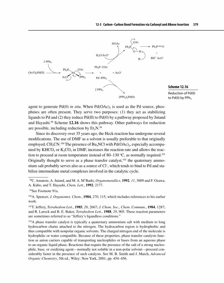
12-3 Carbon–Carbon Bond Formation via Carbonyl and Alkene Insertion 579
agent to generate Pd(0) in situ. When Pd(OAc)2 is used as the Pd source, phos-phines are often present. They serve two purposes: (1) they act as stabilizing ligands to Pd and (2) they reduce Pd(II) to Pd(0) by a pathway proposed by Jutand and Hayashi.98 Scheme 12.16 shows this pathway. Other pathways for reduction are possible, including reduction by Et3N.99
Since its discovery over 35 years ago, the Heck reaction has undergone several modifications. The use of DMF as a solvent is usually preferable to that originally employed, CH3CN.100 The presence of Bu4NCl with Pd(OAc)2, especially accompa-nied by KHCO3 or K2CO3 in DMF, increases the reaction rate and allows the reac-tion to proceed at room temperature instead of 80–130 oC, as normally required.101 Originally thought to serve as a phase transfer catalyst,102 the quaternary ammo-nium salt probably serves also as a source of Cl–, which tends to bind to Pd and sta-bilize intermediate metal complexes involved in the catalytic cycle.
98C. Amatore, A. Jutand, and M. A. M’Barki, Organometallics, 1992, 11, 3009 and F. Ozawa, A. Kubo, and T. Hayashi, Chem. Lett., 1992, 2177. 99See Footnote 91a.100A. Spencer, J. Organomet. Chem., 1984, 270, 115, which includes references to his earlier work.101T. Jeffery, Tetrahedron Lett., 1985, 26, 2667; J. Chem. Soc., Chem. Commun., 1984, 1287; and R. Larock and B. E. Baker, Tetrahedron Lett., 1988, 29, 905. These reaction parameters are sometimes referred to as “Jeffery’s ligandless conditions.”102A phase transfer catalyst is typically a quaternary ammonium salt with medium to long hydrocarbon chains attached to the nitrogen. The hydrocarbon region is hydrophobic and thus compatible with nonpolar organic solvents. The charged nitrogen end of the molecule is hydrophilic or water compatible. Because of these properties, phase transfer catalysts func-tion as anion carriers capable of transporting nucleophiles or bases from an aqueous phase to an organic liquid phase. Reactions that require the presence of the salt of a strong nucleo-phile, base, or oxidizing agent—normally not soluble in a non-polar solvent—proceed con-siderably faster in the presence of such catalysts. See M. B. Smith and J. March, Advanced Organic Chemistry, 5th ed., Wiley: New York, 2001, pp. 454–456.
Scheme 12.16 Reduction of Pd(II) to Pd(0) by PPh3
(AcO)2Pd(II)
2 PPh3
Pd
AcO
Ph3P OAc
PPh3 Pd−PPh3
Ph3P−OAc
+ + AcO−
2 PPh3
(PPh3)3Pd(0)
H2O/AcO−
HOAcPh3P
OAc
O H
B:
Ph3P O
+
BH+ AcO−

580 Chapter 12 Applications of Organometallic Chemistry to Organic Synthesis
Equations 12.45103 and 12.46104 show two examples of intramolecular Heck olefination. In the first case, under Jeffrey’s ligandless conditions, the Pd catalyst also acts to isomerize a C=C bond to give a final product that has the C=N bond in conjugation with the aromatic ring. The second example demonstrates how the Heck reaction can cause alkynes as well as alkenes to undergo 1,2-insertion. The transformation is also a nice application of tandem Pd-catalyzed reactions to create a rather complex ring system.
NH
NI
Me
H
Pd2(OAc)2
KOAc/Bu4NClDMF N
H
N
MeH
LnPd(II) Isomerization
N
N
MeH
(79% yield)
12.45
N
Et2N
CO2Et
CO2Et
Ac
IPd(OAc)2/PPh3
Ag2CO3/HCO2NaMeCN/80 oC N
Et2N
CO2Et
CO2EtI−Pd
Ac
N
Et2NCO2Et
CO2Et
Ac
I−Pd
N
EtO2C
CO2Et
Ac
Et2N
(ca. 60% yield)
12.46
103V. H. Rawal and C. Michoud, J. Org. Chem., 1993, 58, 5583.104R. Grigg, V. Loganathan, and V. Sridharan, Tetrahedron Lett., 1996, 37, 3399.

12-3 Carbon–Carbon Bond Formation via Carbonyl and Alkene Insertion 581
Asymmetric Heck ReactionsThe first examples of asymmetric Heck reactions (AHRs) appeared around 20 years ago, reported almost simultaneously by Shibasaki and Overman. Equations 12.47105 and 12.48106 show these first efforts. Despite the modest enantioselectivi-ties observed, the transformations are notable because they show that tertiary and especially difficult to build quaternary centers can be constructed in a stereo- and regioselective manner. Equation 12.48 also shows an example of tandem Heck reactions in which two cyclizations occur in sequence.
I
CO2Me
Pd(OAc)2(R)-BINAP
N-MePyrrolidoneAg2CO3/60 oC
CO2Me
H
(74% yield; 46% ee)
12.47
O
OTf Pd(OAc)2(R,R)-DIOP
Et3N/PhH/25 oC
O
(90% yield; 45% ee)
12.48
Studies suggest that the mechanism of AHRs is quite similar to the achiral version, which includes the same fundamental steps in the catalytic cycles that we have seen already. The major difference is the presence of chiral bidentate ligands, such as bisphosphines [R2P–Y–PR2], phosphine-phosphites [R2P–Y–P(OR)2], bisphospites [(RO)2P–Y–P(OR)2], aminophosphines [R2N–Y–PR2], or diamines (such as (−)-sparteine), which we encountered earlier in Chapter 12. The bidentate variation of the cationic cycle, shown in Scheme 12.15b, seems to explain most aspects of the mechanism of AHR when X = OTf or I (in the presence of halide scavengers). Throughout the cycle, the ligand remains bidentate, and this factor seems to enhance enantioselectivity. The neutral cycle variant, which ought to be
105Y. Sato, M. Sodeoka, and M. Shibasaki, J. Org. Chem., 1989, 54, 4738.106N. E. Carpenter, D. J. Kucera, and L. E. Overman, J. Org. Chem., 1989, 54, 5846.
How does the last intermediate in equation 12.46 transform to the final product? What kind of reaction must occur in this step?
Exercise 12-10

582 Chapter 12 Applications of Organometallic Chemistry to Organic Synthesis
similar to Scheme 12.15a, may involve the dissociation of one chelating atom from Pd, and this could diminish enantioselectivity. Although either coordination of the alkene to Pd or migratory insertion could lead to enantiodifferentiation, a recent theoretical (DFT) and experimental study, using chiral aminophosphines (R)- and (S)-36 as the bidentate ligand, indicated that the migratory insertion of alkene is the step responsible for asymmetric induction.107 The study also found that the less favored of the diastereomeric complexes leading to insertion was more reactive than the more stable complex, exactly the same kind of situation observed by Halpern in his investigation of asymmetric hydrogenation. It is not clear at this time whether these results apply to other systems.
S
N
Ph
PPh2
(R)-36
S
N
Ph
PPh2
(S)-36
Besides enantioselectivity, another concern in AHRs is the regioselectivity of β-hydride elimination. Scheme 12.17 shows two scenarios that could result once migratory alkene insertion occurs to give intermediate 37.108 Path b results in the destruction of the chirality center, whereas path a preserves it. This is a serious problem for intermolecular AHRs, but less so for the intramolecular ver-sion. Thus, it is not surprising that most good examples of AHR involve intramo-lecular cyclization to form five- and six-membered rings, as Scheme 12.17 (path a) shows. Elimination of HPdX from carbons 2 and 3 gives the more substituted alkene, which destroys the chirality center, but this is not likely because that would involve anti elimination.109 Loss of hydrogen from C1, on the other hand, involves syn elimination; the chirality center is preserved.
Another scenario for AHRs is the formation of quaternary chirality centers. Here, β-elimination via path b is impossible (when Hb is replaced by a hydrocar-byl group). The downside, however, is that construction of such centers is diffi-cult because it requires the insertion of trisubstituted C=C bonds, which normally react sluggishly in Heck reactions. Some of this lack of reactivity, however, can
107S. T. Henriksen, P.-O. Norrby, P. Kaukoranta, and P. G. Andersson, J. Am. Chem. Soc., 2008, 130, 10414.108A. B. Dounay and L. E. Overman, Chem. Rev., 2003, 103, 2945, and Footnote 91a.109In the intermolecular process, rotation about the C2−C3 bond could occur, leading to syn-elimination. With a rigid ring system as shown in Scheme 12.17, this is not possible.

12-3 Carbon–Carbon Bond Formation via Carbonyl and Alkene Insertion 583
be overcome in intramolecuar Heck reactions because entropy constraints are minimized. Judicious choice of solvent and coreactants can also enhance yields, making this transformation one of the best ways of creating quaternary centers (see also Section 12-1-2). A rather spectacular demonstration of the use of Heck olefination to create a quaternary center, albeit a racemic transformation, was used in the synthesis of the alkaloid (±)-gelsemine (equation 12.49).110
MeO2CNOMe
N
I
O
Y
Y = CH2OCH3
MeO2CN
[Pd2(dba)3-CHCl3]
Ag3PO4/Et3N/THF
(78% yield of major product;11 : 1 mixture of products)
NY
OMeO
Br
MeO2CNOMe
Br
Br
N
Y
O
+
(±)-gelsemine
12.49
Equation 12.50 demonstrates an application of AHR to form a quaternary chiral-ity center using (R)-tol-BINAP (same as BINAP except o-tolyl replaces Ph) as the bidentate ligand.111 Another good example is shown in equation 12.51, where
110A. Madin, C. J. O’Donnell, T. Oh, D. W. Old, L. E. Overman, and M. J. Sharp, J. Am. Chem. Soc., 2005, 127, 18054.111S. Honzawa, T. Mitzutani, and M. Shibasaki, Tetrahedron Lett., 1999, 40, 311 and T. Mitzutani, S. Honzawa, S.-Y. Tosaki, and M. Shibasaki, Angew. Chem. Int. Ed., 2002, 41, 4680.
Scheme 12.17 Regioselectivity and the Heck Reaction
+ RPdX
R = aryl, vinyl
PdX
HbH
Ha R1 2 3
a
b
R
R
3
21
1 2
3
+ HaPdX
+ HbPdX
syn-Elimination
anti-Elimination
37

584 Chapter 12 Applications of Organometallic Chemistry to Organic Synthesis
(S)-BINAP is used as the chiral ligand.112 The AHR continues to find wide use in synthesis as a means of installing tertiary and quaternary chirality centers.113
OO
OTBDPS
Me
TfO
MeYO
H
Y = CH2OCH3TBDPS = t-Butyldiphenylsilyltol-BINAP = o-tolyl replaces Ph
Pd(OAc)2(R)-tol-BINAP
K2CO3/PhMe
O
OMeYO
MeTBDPSO
H
+ diastereomer
(96% ee)
11 : 1
12.50
OMe
OMe
Me
TBDPSO
OTf Pd(OAc)2(S)-BINAP
K2CO3/THF/60 oC
MeOTBDPS
OMe
OMe
(78% yield; 87% ee)
12.51
12-4 CARBON–CARBON BOND FORMATION VIA TRANSMETALATION REACTIONS (CROSS-COUPLING REACTIONS)
12-4-1 IntroductionRepresenting the third important method of C−C bond formation covered in Chapter 12, cross-coupling reactions constitute one of the most powerful and widely used tools available today to the synthesis chemist. Equation 12.52 shows the general overall reaction, which involves combination of two carbon fragments (R and R′), one typically originating from an organohalide and the other from a metal hydrocarbyl compound. A transition metal complex serves as catalyst and template for the coupling to occur.
R′−X + M′−R → R′−R + M′−X 12.52
112A. Kojima, T. Takemoto, M. Sodeoka, and M. Shibasaki, J. Org. Chem., 1996, 61, 4876.113For reviews of the AHR, see Footnote 108 and M. Shibasaki, E. M. Vogl, and T. Oshima, Adv. Synth. Catal, 2004, 346, 1533.

12-4 Carbon–Carbon Bond Formation via Transmetalation Reactions (Cross-Coupling Reactions) 585
The variety of carbon fragments that can join and the general tolerance of the reaction conditions to functional groups already present on these fragments lead to countless possibilities for rapid construction of complex molecules, especially biologically active compounds. One key difference between cross-coupling reac-tions and the Tsuji–Trost allylation or Heck olefination is the occurrence of a transmetalation step during the catalytic cycle.
Transmetalation, according to general equation 12.53, is an excellent method for introducing σ-bonded hydrocarbon ligands into the coordination sphere of transition metals. The equilibrium is thermodynamically favorable from left to right if the electronegativity of M (usually a mid- to late-transition metal) is greater than that of M′ (often a main group or early-transition metal) and is kinet-ically favorable if an empty orbital is available on both metals.114
M′−R + M−X M−R + M′−X 12.53
Table 12-5 shows a portion of the periodic table with Pauling electronegativities listed below each element.115 Use of these electronegativity values in conjunction with equation 12.53 allows one to predict whether a particular transmetalation is favorable or unfavorable.
Organolithium and magnesium reagents (containing highly electropositive metals, M′) are the most reactive transmetalation reagents. Unfortunately, these compounds are too reactive toward many functional groups, which might also be present in the substrates that are joined in cross-coupling. Less reactive organozir-conium, zinc, tin, boron, and aluminum compounds often possess just the right amount of reactivity to be useful in transferring σ-bonded hydrocarbyl ligands to M without affecting functional groups on ligands already attached to M. Even if transmetalation is not favorable thermodynamically, based on electronegativity differences between M and M′, the reaction is often useful because even small concentrations of transmetalation product can react in a subsequent irreversible step, thus driving the equilibrium.
114E-i. Negishi, Organometallics in Organic Synthesis, Wiley: New York, 1980, pp. 54–56.115It should be pointed out that the Pauling electronegativities listed in Table 12-5 indeed support the theory that transmetalation among Pd, Rh, Ru, or Pt and a variety of more elec-tropositive metals should readily occur based on thermodynamic grounds. It must also be emphasized, however, that more recent determinations of electronegativities, based on both high-level theoretical calculations and experiment, indicate that Pauling-scale electronega-tivity values of second- and third- row transition metals of Groups 8, 9, and 10 are probably too high (see J. B. Mann, et al., J. Am. Chem. Soc., 2000, 122, 5132, and references therein). It may be that transmetalations to Pd, for example, which appear to be infeasible on the basis of electronegativity differences, are feasible because of the irreversibility of subsequent steps in a catalytic cycle.

586 Chapter 12 Applications of Organometallic Chemistry to Organic Synthesis
Table 12-5 Electronegativitiesa of Selected Elements Useful in Synthesis
Li B C0.98 2.04 2.55Na Mg Al Si0.93 1.31 1.61 1.90K Ca Sc Ti V Cr Mn Fe Co Ni Cu Zn0.82 1.00 1.36 1.54 1.63 1.66 1.55 1.83 1.88 1.91 1.90 1.65
Zr Mo Ru Rh Pd Ag Sn1.33 2.16 2.2b 2.28 2.20 1.93 1.96
W Os Ir Pt Au Hg Tl Pb 2.36 2.2b 2.20 2.28 2.54 2.00 1.62 2.33
aPauling electronegativities taken from A.L. Allred, J. Inorg. Nucl. Chem., 1961, 17, 215.bEstimated.
Transmetalation may proceed via a concerted σ bond metathesis, involving a four-center transition state (38) (or even a metallacyclobutane intermediate) that leads to transfer of the organic group R to M with retention of configuration.
M'
X M
R
38
Other mechanisms are possible, however. For example, the original mechanism proposed for the transmetalation step in Stille coupling (Section 12-4-2) involved an acyclic SE2 (Section 8-4-1) pathway (equation 12.54), which proceeds through transition state 39 such that R is transferred with inversion of configuration.116 We will further discuss this dichotomy in Section 12-4-2.
C SnR''3Pd
HD
Cl
L
R'
L2PdR'Cl C SnR''3
Ph
H D
+ L2R'Pd C
Ph
HD
+ ClSnR''3
39
δ+
δ−
δ+L
L
12.54
Palladium is by far the most useful transition metal (M) involved as the acceptor metal in synthetically useful cross-coupling reactions. There are several different types of cross-couplings involving transmetalation to Pd, and the rest of this section will consider four of the most commonly used and useful of these.
116J. K. Stille, Angew. Chem. Int. Ed. Engl., 1986, 25, 508.

12-4 Carbon–Carbon Bond Formation via Transmetalation Reactions (Cross-Coupling Reactions) 587
Table 12-6 lists these four types, showing both the differences and the similarities among them.
Scheme 12.18 outlines the general catalytic cycle for cross-coupling, the key steps of which are (a) oxidative addition of R′−X to Pd(0), (b) cis–trans isomeri-zation of a square planar Pd complex (if necessary), (c) transmetalation of R−M′ to give R′−Pd−R, (d) trans–cis isomerization (if necessary), and (e) reductive elimination of R′−R and regeneration of Pd(0).
12-4-2 Stille Cross-CouplingEarly efforts by Eaborn117 and Kosugi,118 who independently studied transmetala-tions between Pd and organotin compounds, laid the groundwork for extensive research by Stille into the mechanism and scope of Pd-catalyzed cross-coupling involving stannanes as transmetalating agents.119 In honor of his widely encom-passing investigations, the reaction is now known as Stille cross-coupling, or the Stille reaction. In addition to allowing a variety of carbon fragments to join, Stille cross-coupling is broadly useful as a means of constructing new C−C bonds for
117D. Azarian, S. S. Dua, C. Eaborn, and D. R. M. Walton, J. Organometal. Chem., 1976, 117, C55.118M. Kosugi, K. Sasazawa, Y. Shimizu, and T. Migita, Chem. Lett., 1977, 301 and M. Kosugi, Y. Shimizu, and T. Migita, Chem. Lett., 1977, 1423.119First report: D. Milstein and J. K. Stille, J. Am. Chem. Soc., 1978, 100, 3636; see also Footnote 116.
Table 12-6 Synthetically Useful Pd-Catalyzed Cross Coupling Reactionsa
R′−X + M′−R R′−R + M′−X LnPd(0)
Name M′ L First reported
Stille Sn PY3b 1976–1978
Suzuki B PY3c 1979
Sonogashira Cu PY3d 1975
Negishi Zn PY3e 1977
aX = I, Br, Cl, OTf, or OPO(OR″)2 (R″ = simple alkyl group); R and R′ are typically aryl, vinyl, allyl, benzyl, or acyl (R only), although alkyl groups can be used if β-elimination can be suppressed.bY = Ph, 2-furyl; PdCl2(MeCN)2 and [Pd2(dba)3] are also useful catalysts.cY=Ph, o-tolyl; PdCl2(dppf) is also a useful catalyst [dppf = 1,1′-bis(diphenylphosphino)ferrocene].dY=Ph; PdCl2(MeCN)2 and PdCl2(PPh3)2 are also widely used.eY = Ph, 2-furyl; [Pd2(dba)3] is also widely used.
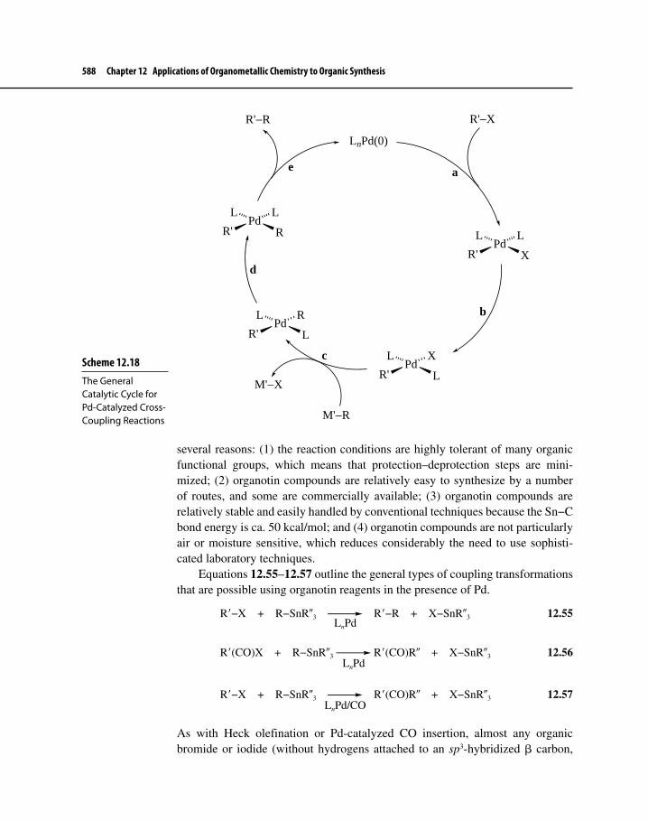
588 Chapter 12 Applications of Organometallic Chemistry to Organic Synthesis
several reasons: (1) the reaction conditions are highly tolerant of many organic functional groups, which means that protection–deprotection steps are mini-mized; (2) organotin compounds are relatively easy to synthesize by a number of routes, and some are commercially available; (3) organotin compounds are relatively stable and easily handled by conventional techniques because the Sn−C bond energy is ca. 50 kcal/mol; and (4) organotin compounds are not particularly air or moisture sensitive, which reduces considerably the need to use sophisti-cated laboratory techniques.
Equations 12.55–12.57 outline the general types of coupling transformations that are possible using organotin reagents in the presence of Pd.
R′−X + R−SnR″3 R′−R + X−SnR″3 12.55LnPd
R′(CO)X + R−SnR″3 R′(CO)R″ + X−SnR″3 12.56LnPd
R′−X + R−SnR″3 R′(CO)R″ + X−SnR″3 12.57LnPd/CO
As with Heck olefination or Pd-catalyzed CO insertion, almost any organic bromide or iodide (without hydrogens attached to an sp3-hybridized β carbon,
Scheme 12.18 The General Catalytic Cycle for Pd-Catalyzed Cross-Coupling Reactions
LnPd(0)
PdR'
L L
X
PdR'
L X
L
PdR'
L R
L
PdR'
L L
R
R'−X
M'−R
M'−X
R'−R
a
b
c
d
e

12-4 Carbon–Carbon Bond Formation via Transmetalation Reactions (Cross-Coupling Reactions) 589
of course) will serve as an electrophile and undergo coupling with the organo-tin reagent (equation 12.55). Usually, the organotin compound is designed so that one group will transfer preferentially over the rest. The order of transfer is approximately as follows.
RC≡C > RCH=CH > aryl > allyl – benzyl > CH3(C=O)CH2 > alkyl
Methyl or butyl groups typically comprise the remaining, nontransferable groups in the stannane (the R″ groups in equations 12.55-12.57).120 Acyl chlorides react to give ketones (equation 12.56), or alternatively, R′−X reacts in the presence of CO to yield the same result (equation 12.57). Use of the alternate path to ketones works when the acid chloride is not readily available or if the presence of an acyl chloride group is incompatible with the presence of protic functional groups such as OH or NH2. Pd(PPh3)4 or PdCl2(MeCN)2 are particularly useful catalysts for Stille coupling (the latter Pd(II) complex is likely reduced in situ). Table 12-7 summarizes the broad scope of Stille cross-coupling. In general, any electrophile listed in the first column will couple with any stannane from the second column.
Reaction MechanismAmong all four cross-coupling reactions we will consider, the Stille reaction has been the most investigated. Although any of the five steps in the general cycle
120Tetraalkyltin reagents will react—albeit more slowly than those containing Sn—C(sp2) or Sn—C(sp) bonds—if the transfer of a simple alkyl group is desired.
Propose a catalytic cycle for the cross-coupling plus carbonylation described by equation 12.57.
Exercise 12-11
Table 12-7 Electrophiles and Organotin Reagents Suitable for Coupling Reactions
Electrophile Organotin reagent
R′(C=O)Cl H−SnR3
R′R″C=CR‴−CH2−X (allyl) R‴C≡C−SnR3
ArCH2−X (benzyl) R′R″C=CR‴−SnR3
R′R″C=CR‴−X Ar−SnR3
Ar−X R′R″C=CR‴−CH2−SnR3
R′−C(H)(X)−CO2R″ Ar−CH2−SnR3
R′−SnR3 (R′ = alkyl)X = Br, I (Cl also works, but special conditions are required)
R′, R″, R‴ = a wide variety of hydrocarbyl groups; R = Me, Bu

590 Chapter 12 Applications of Organometallic Chemistry to Organic Synthesis
shown in Scheme 12.18 could be the slow step, transmetalation is most often rate determining. If that is the case, transferable groups attached to Sn may have β-hydrogens attached to sp3 carbons, because steps subsequent to transmetalation are rapid.
Experimental evidence points to two different modes of oxidative addition. For R′−X, when R′ is sp2 hybridized, a three-centered mechanism seems to apply (see also Section 7-2-2). This leads to an intermediate where R′ and X are cis. Because of the high trans effect of R′, a rapid cis–trans rearrangement likely occurs to give the more stable stereoisomer (equation 12.58).121
X
Pd
L
L
+ Pd
L
L XPd
L
L X
Pd
L
X L
12.58
When R = allyl, OA seems to involve either an SN2 mechanism (inversion of configuration) or a mechanism that goes through a three-centered transition state (retention of configuration). Inversion is the stereochemical outcome in polar, coordinating solvents such as DMSO or acetonitrile, whereas retention is found with use of less polar and less coordinating solvents such as THF, benzene, and CH2Cl2.122
The attachment of a new carbon ligand to Pd during transmetalation amounts to a ligand substitution, and mechanistic studies show support for an associa-tive mechanism overall, which is typical for square planar Pd complexes. Details of the transmetalation step have been elucidated experimentally and compu-tationally at the DFT level, and two major pathways seem to be operative.123 Transmetalations run in less coordinating solvents, such as toluene, CH2Cl2, or THF, go via path a (Scheme 12.19), which involves cyclic transition state 40 and intermediate 41. This route results in retention of configuration at the α carbon of R. This path seems especially favorable for X = Br or I and also when Cα is sp2 hybridized. For Stille couplings run in coordinating polar, aprotic solvents, such as HMPA or DMSO, an “open” pathway (path b, Scheme 12.19) is preva-lent, especially if X = OTf. The stereochemical consequence of path b is inversion
121A. L. Casado and P. Espinet, Organometallics, 1998, 17, 954.122H. Kurosawa, S. Ogoshi, Y. Kawasaki, S. Murai, M. Miyoshi, and I. Ikeda, J. Am. Chem. Soc., 1990, 112, 2813; H. Kurosawa, H. Kajimura, S. Ogoshi, H. Yoneda, K. Miki, N. Kasai, S. Murai, and I. Ikeda, J. Am. Chem. Soc., 1992, 114, 8417; and A. Vitagliano, B. Åkermark, and S. Hansson, Organometallics, 1991, 10, 2592.123(a) A. Nova, G. Ujaque, F. Maseras, A. Lledós, and P. Espinet, J. Am. Chem. Soc., 2006, 128, 14571; (b) R. Álvarez, O. N. Faza, A. R. de Lera, and D. J. Cárdenas, Adv. Synth. Catal., 2007, 349, 887; (c) M. H. Pérez-Temprano, A. Nova, J. A. Casares, and P. Espinet, J. Am. Chem.. Soc., 2008, 130, 10518; and (d) R. Álvarez, M. Pérez, O. N. Faza, and A. R. de Lera, Organometallics, 2008, 27, 3378.

12-4 Carbon–Carbon Bond Formation via Transmetalation Reactions (Cross-Coupling Reactions) 591
of configuration. The poor coordinating ability of triflate ion and the presence of highly polar solvents lend support to formation of cationic intermediate 42 and cis- and trans-transmetalation products 44 and 45. Transition state 43 connects intermediate 42 with these products via an SE2 transmetalation route.
Reductive elimination (Section 7-3) must necessarily proceed from an inter-mediate where R′ and R are cis to each other. Between transmetalation and reduc-tive elimination, trans–cis isomerization (45 → 44) must occur, although it is interesting to note that path a in Scheme 12.19 yields reactive T-shaped complex 46 directly from cyclic intermediate 41. We would, therefore, expect that RE would not be the rate-determining step in cross-coupling reactions going through path a. RE as a result of path b may be slow, especially if the carbon group transferred from Sn is allyl.124 Although the general scheme for cross-coupling (Scheme 12.18) gives a good overview of the catalytic cycle for Stille cross-coupling, it does not explain many of the subtleties of the transformation including different stereochemical outcomes as a function of reaction conditions. Scheme 12.19 sheds some light on the stereochemical characteristics of the transmetala-tion step, such as retention of configuration throughout coupling of two vinyl
124It may be that the relatively weak allyl–R′ bond makes RE less favorable both thermo-dynamically and kinetically. For an excellent summary of recent mechanistic studies of the Stille cross-coupling reaction, see P. Espinet and A. M. Echavarren, Angew. Chem. Int. Ed., 2004, 43, 4704.
Scheme 12.19 A Mechanism for Stille Cross-Coupling
R'
Pd LL
X
R'
PdR
XR''3Sn
RSnR''3R'
Pd LR
XR''3Sn
R Pd
R'
L
Solv
R'
Pd LL
Solv
X−
L
L
LR''3Sn−X
OARE
Pd
R'
SolvL
L
C SnR''3
R'
Pd
L
CL
C SnR''3
δ+
δ+X−
R''3Sn−X+
Solv
L
Pd
L
CR'
Path a:
Path b:
40
X = I, Br; R is sp2 hybridized
X = OTf; R is sp3 hybridized
46
41
42434445
R−R' + LnPd
RE
LnPd + R'−X

592 Chapter 12 Applications of Organometallic Chemistry to Organic Synthesis
groups, but fleshing out all the details of the Stille cross-coupling mechanism will likely engage chemists for years to come.
Synthesis ApplicationsWe have just seen that Stille coupling occurs chemo- and regioselectively and with predictable stereochemistry, especially when aryl and vinyl groups are pres-ent as either R′ or R. Chemists have put this selectivity to good use in hundreds and hundreds of examples that have appeared in the chemical literature over more than two decades.
Equations 12.59–12.62 show a few examples of the utility and enormous potential of Stille cross-coupling in the construction of key C−C bonds found in complex natural products.125
O
SnBu3
Me
OTf
Me
O Me
Me
Me O
Me
Me
O Me
Me
Me
O47
(53% yield)
Pd(MeCN)2(PPh3)2
DMF/LiClCO (3 bar)
125For a nice summary of the use of Stille cross-coupling in natural product synthesis, see K. C. Nicolaou, P. G. Bulger, and D. Sarlah, Angew. Chem. Int. Ed., 2005, 44, 4442.
Exercise 12-12 Complete the following reactions and specify the stereochemistry of the coupled product.
I
MeO
+Bu3Sn
PhLnPd(0)
Cl
CO2Me
+Bu3Sn CO2CH2Ph LnPd(0)
12.59

12-4 Carbon–Carbon Bond Formation via Transmetalation Reactions (Cross-Coupling Reactions) 593
I
NCbz
NCbz
CO2t-BuTBDMSO
H
TBDMS = t-Butyldimethylsilyl
+
Me3Sn
NCbz
NCbz
CO2t-BuTBDMSO
H
[Pd2(dba)3]
AsPh3/DMF/45 oC
NCbz
NCbz
CbzN
CbzN
H
OTBDMS
TBDMSO
Ht-BuO2C
CO2t-Bu
(83% yield)
C
O
OCH2PhCbz = 12.60
O
OAc
O
O
O
O
AcO
TBDMSO
Me
Me
OHH
Me
H
HHO
NO
Me
Me
OSiEt3
Me
SnMe3
Teoc
+
[Pd2(dba)2]AsPh3/i-Pr2NEtLiCl/NMP
O
OAc
O
O
O
O
TBDMSO
Me
Me
OHH
Me
H
HH
ON
O
Me
Me
OSiEt3
Me
Teoc
(55% yield)
NMP = N-Methylpyrrolidone
Teoc =O
O
SiMe3
H
H
12.61
Equation 12.59 shows an intramolecular cross-coupling combined with a carbonylation, which was used in the synthesis of (±)-epi-jatrophone (47), a diter-pene that possesses antitumor activity.126 Early in investigations on the reactivity
126A. C. Gyorkos, J. K. Stille, and L. S. Hegedus, J. Am. Chem. Soc., 1990, 112, 8465.

594 Chapter 12 Applications of Organometallic Chemistry to Organic Synthesis
I
MeN
OI
Me
Me
OH
Me
H
OH
H
OMe
OMe
Me
OMe
Me
OHH
O
Me
O
O
O
O
+Bu3Sn
SnBu3
PdCl2(MeCN)2
i-Pr2NEtDMF/THF/25 oC
I
MeN
O
Me
Me
OH
Me
H
OH
H
OMe
OMe
Me
OMe
Me
OHH
O
Me
O
O
O
O
SnBu3
MeN
O
Me
Me
OH
Me
H
OH
H
OMe
OMe
Me
OMe
Me
OHH
O
Me
O
O
O
O
(27% overall yield)
48
49
Addedfragment
12.62
of triflate esters, the addition of LiCl was found to enhance reactivity of R′−OTf, but the reason for this is still not completely understood.127 An intermolecular
127Some recent work has shed light on the efficacy of LiCl. Theoretical investigation of the reaction of vinyl triflates in Stille cross-coupling has shown that LiCl reacts with LnPd(0) to

12-4 Carbon–Carbon Bond Formation via Transmetalation Reactions (Cross-Coupling Reactions) 595
aryl–aryl coupling is pictured in equation 12.60.128 This transformation was an important step in the synthesis of himastatin, a microbial metabolite with anti-bacterial and antitumor properties. Another intermolecular Stille reaction is detailed in equation 12.61.129 Here coupling involves R′−X attaching to Pd in an η3-manner, so the reaction demonstrates features of both Stille cross-coupling and the Tsuji–Trost reaction. A rather spectacular example of cascading inter- and intramolecular Stille reactions appears in equation 12.62,130 and this was used to synthesize the antibiotic rapamycin (49). Note the lack of protecting groups on the oxygen functional groups attached to diiodide 48.
12-4-3 Suzuki Cross-CouplingFirst reported in 1979 by Suzuki and Mayaura, Suzuki cross-coupling (also called the Suzuki–Mayaura reaction) is an extremely versatile and useful means of forming C−C bonds.131 Typical reaction conditions are shown in equation 12.63. Although the transmetalating agent, R−B(R″)2, is different, the scope of the reaction is quite similar to that of Stille cross-coupling (see Table 12-7). This is not surprising on the basis of electronegativity differences between Pd and M′ because the eletronegativities of B and Sn are nearly equal according to Table 12-5.
form an anionic complex [L2PdCl]–, which then is more reactive in OA of vinyl triflates than LnPd(0). See Footnote 123d.128T. M. Kamenecka and S. J. Danishefsky, Chem. Eur. J., 2001, 7, 41. Note that Ph3As is used in this reaction. Sometimes it is used instead of phosphine ligands because it is less strongly coordinating to Pd. Because L-type ligands must attach and depart from Pd during the catalytic process, use of Ph3As can sometimes speed up cross-coupling.129K. C. Nicolaou, T. V. Koftis, S. Vyskocil, G. Perovic, T. Ling, Y. M. A. Yamada, W. Tang, and M. O. Frederick, Angew. Chem. Int. Ed., 2004, 43, 4318.130K. C. Nicolaou, A. D. Piscopio, P. Bertinato, T. K. Chakraborty, N. Minowa, and K. Koide, Chem Eur. J., 1995, 1, 318.131N. Miyaura and A. Suzuki, J. Chem. Soc. Chem. Comm., 1979, 866 and N. Miyaura, K. Yamada, and A. Suzuki, Tetrahedron Lett., 1979, 3437.
What are the starting materials required to synthesize compound 50 using a Stille cross-coupling reaction?
O
50
Exercise 12-13

596 Chapter 12 Applications of Organometallic Chemistry to Organic Synthesis
R, R', L: see Tables 12-6 and 12-7R'': alkyl, OH, O-alkylBase: MOH (M = Na, Tl), M2CO3 (M = Na, K, Cs), MF (M = K, Cs), NaOMe, K3PO4
R'−X R−BR''2LnPd(0)
R'−R X−BR''2Base
+ +
12.63
Organoboranes, borates, and boronic acids are readily available (hundreds are sold commercially) or they are easily synthesized (for example, hydroboration of the 1-position of terminal alkynes yields 1-borylalkenes). These compounds react with R′−X under mild Pd-catalyzed conditions, and the inorganic byproducts are easily removed at the end of the reaction. Moreover, boranes, borate esters, and boronic acids are tolerant of most common functional groups and are sometimes even compatible with water, which is one of the green aspects of Suzuki cross-coupling. Another important characteristic of organoboron reagents, which makes the Suzuki cross-coupling a greener reaction than the Stille version, is their rela-tively low toxicity, especially comparedwith highly toxic organotin compounds.132
Although Stille cross-coupling still finds wide use among synthesis chemists, the Suzuki reaction has become the method of choice in recent years.133
Reaction MechanismThe first two and last two steps for the catalytic cycle of Suzuki cross-coupling are much the same as those for the Stille reaction (Scheme 12.18); the transmeta-lation step, however, is unique. Transmetalation involves transfer of R to Pd from a borane, borate ester, or boronic acid. Both recent experimental investigations and analysis using DFT calculations indicate that transmetalation is not simply a concerted process as suggested by transition state structure 38.
Early in his investigation of the reaction, Suzuki determined that the addi-tion of base was necessary for smooth cross-coupling.134 Although many different bases will work, the simplest bases (OY–), OH–, and alkoxides, seem to act in either of two ways. Scheme 12.20 shows how OY– can either react with the borate
132Recent research has uncovered reaction conditions that allow coupling of vinyl and aryl halides with a vinyltin partner, which is generated in situ using a catalytic amount of Me3SnCl. These conditions drastically reduce the toxic hazard posed by handling, use, and disposal of stoichiometric amounts of organotin coupounds. Although it remains to be seen whether this method will be general, preliminary results were encouraging. See W. P. Gallagher and R. E. Malezcka Jr., J. Org. Chem., 2005, 70, 841.133A search of the literature by one of the authors for years 2006–2008 found 176 hits for Stille cross-coupling and 961 hits for the Suzuki reaction.134For a brief summary of Suzuki’s work in discovering and developing Suzuki cross- coupling, see A. Suzuki, Chem. Commun., 2005, 4749.

12-4 Carbon–Carbon Bond Formation via Transmetalation Reactions (Cross-Coupling Reactions) 597
or boronic acid to give an anionic species, which then undergoes transmetala-tion with Pd (path a), or react directly with LnR′PdX, displacing X– and giving LnR′PdOY.135 This latter path continues via transmetalation of R−B(OY)2 to Pd to yield LnPdRR’ and B(OY)3 (path b).
Several steps are apparently involved in transmetalation according to calculations, and these investigations also suggest that different mechanistic path-ways exist during transmetalation beginning with either a cis- or trans-L2R′PdX intermediate.136 As we found with Stille cross-coupling, transmetalation seems more likely to proceed through an associative pathway rather than dissociative. At some point during transmetalation, a cyclic transition state occurs (not necessarily a four-centered one) that allows transfer of R to Pd.
135N. Miyaura, Top. Curr. Chem., 2002, 219, 11.136(a) A. A. C. Braga, G. Ujaque, and F. Maseras, Organometallics, 2006, 25, 3467; (b) L. J. Goossen, D. Koley, H. Hermann, and W. Thiel, Organometallics, 2006, 25, 54; (c) C. Sirce, A. A. C. Braga, F. Maseras, and M. M. Cid, Tetrahedron, 2008, 64, 7437; and (d) Y.-L. Huang, C.-M. Weng, and F.-E. Hong, Chem. Eur. J., 2008, 14, 4426.
Scheme 12.20Pathways for the Action of Base during Transmetalation
LnPd(0)
PdR'
L L
RPd
R'
L X
L
R B
OR''
OR''OY−
OY
BR
OR''OR''
B(OR'')2(OY) + X−
trans-to cis-isom. OY−
X−
PdR'
L OY
L
R−B(OR'')2
(R''O)2B
YO Pd
R
L
L
R'
B(OR'')2(OY)
R'−XR'−R
Path a
Path b
trans-to cis-isom.

598 Chapter 12 Applications of Organometallic Chemistry to Organic Synthesis
Synthesis ApplicationsAs with Stille cross-coupling, use of the Suzuki reaction has had a dramatic effect on organic synthesis.137 The chemo-, regio-, and stereoselectivity observed with Suzuki cross-coupling are quite similar to those observed for the Stille reaction. Equations 12.64–12.67 show some of the scope of Suzuki cross-coupling.
PhCH2O
BO
O
OMeO
NCbz
+
NH
O
NBoc
O
Me
Me
I
NH
O
NBoc
O
Me
Me
PhCH2O
OMe
O
NHCbz
(75% yield)
PdCl2(dppf)
CH2Cl2/DMEK2CO3/80 oC
Boc: t-Bu-O(C=O)O-DME: MeOCH2CH2OMe
12.64
B
O
O
Me MeMe Me
Me
+
NH
OH
I
Me
O Me
NH
Me
Me
Me
Me
O
Me OH
Me
Me
51
(44% yield)
Pd(OAc)2/TPPTSi-PrNEt2MeCN/H2O/25 oC
12.65
137For example, Suzuki cross-coupling was a key step in the synthesis of palytoxin, per-haps the most potent nonpeptide toxin known, which is isolated from coral. Palytoxin pos-sesses over 70 stereogenic centers (which means that the number of stereoisomers possible approaches Avogadro’s number!) and has a molecular weight of 2680 Da, making it the heaviest secondary metabolite to be synthesized to date. For a report on the synthesis of palytoxin, see E. M. Suh and Y. Kishi, J. Am. Chem. Soc., 1994, 116, 11205.

12-4 Carbon–Carbon Bond Formation via Transmetalation Reactions (Cross-Coupling Reactions) 599
OH
BF3K
O
O
OCH2Ph
Br
OMOMPd(PPh3)4
Cs2CO3/THF/H2OReflux
O
OH O OMOM
PhCH2O
(42% yield)52 12.66
S
N Me
Me
I
OAc
OTBDMS
Me Me
PhCH2O OTBDMS
Me Me
B
+
OTBDMS
Me Me
PhCH2O OTBDMS
Me Me
OAc
Me
S
N
Me
Pd(dppf)Cl2
Cs2CO3/DMFH2O/25 oC
53
(60% yield)
12.67
The Suzuki reaction is today the most widely used method for aryl–aryl coupling, and equation 12.64 demonstrates one example. In this case, aryl–aryl coupling was a key step in the synthesis of proteasome inhibitor TMC-95A.138 Equation 12.65 shows a vinyl–vinyl coupling that leads to myxalamide A (51), a potent antibacterial and antifungal compound.139 Here, the R group is transferred from a borate ester. Intramolecular Suzuki cross-coupling is read-ily feasible, and equation 12.66 shows a nice example, which was employed for the synthesis of the antitumor compound oximidine II.140 Fluoroborate salt 52 found use here, instead of the usual borate ester or boronic acid, because it is relatively stable and easily handled. Suzuki cyclization occurred under mild conditions at high dilution of substrate in order to prevent intermolecular cross-coupling.
138S. Lin and S. J. Danishefsky, Angew. Chem. Int. Ed., 2002, 41, 512. Proteasome inhibitors block the breakdown of proteins in the cell, and these may be effective in fighting the growth of tumor cells.139A. K. Mapp and C. H. Heathcock, J. Org. Chem., 1999, 64, 23.140G. A. Molander and F. Dehmel, J. Am. Chem. Soc., 2004, 126, 10313; see also G. A. Molander and N. Ellis, Acc. Chem. Res., 2007, 40, 275, for a recent review on the use of organotrifluoroborates in Suzuki cross-coupling.

600 Chapter 12 Applications of Organometallic Chemistry to Organic Synthesis
The last example (equation 12.67) shows so-called B-alkyl cross-coupling in which an sp3 hybridized carbon is transferred from boron to Pd.141 This reaction produced fragment 53, which was used to synthesize epothilone A. Epothilones were mentioned in Section 11-1-3, and they are a family of macrocyclic compounds that appear to be very effective in fighting breast and uterine cancers. Reaction conditions were adjusted for B-alkyl cross-coupling such that β-elimination of the alkyl group transferred to Pd was suppressed. One way of doing this is to use the diphosphine complex PdCl2(dppf). The naturally large bite angle (βn) of dppf is such that when R and R′ are cis to one another, they are closer than would be in the case when monodentate or other bidentate phosphines are attached to Pd. Reductive elimination is then quite facile and occurs before β-elimination can occur. R-BBN derivatives are also quite reactive during transmetalation if the base is carefully chosen. Note that the group transferred in equation 12.67 is pri-mary. Secondary alkyl groups will transfer, although at a much slower rate, thus making this reaction not nearly as useful synthetically. This is, however, an active area of research.
Further DevelopmentsOne of the key problems associated with the Suzuki cross-coupling was the lack of reactivity of aryl chlorides. This is unfortunate, because chlorinated aromat-ics are usually much cheaper and more readily available than other haloarenes. Equation 12.68 shows a solution to this problem where the addition of the base Cs2CO3 and P(t-Bu)3, a sterically hindered and electron-rich phosphine, led to successful coupling of an aryl chloride and arylboronic acid.142
Me Cl (HO)2B+[Pd2(dba)3]
P(t-Bu)3
Cs2CO3
1,4-dioxane/80 oC
Me
(86% yield)
12.68
Buchwald also developed favorable conditions for coupling aryl chlorides. Instead of using P(t-Bu)3, which is pyrophoric, he reported that phosphine 54 in the pres-ence of the base K3PO4 allowed cross-coupling of aryl chlorides and arylboronic acids (equation 12.69).143
141B. Zhu and J. S. Panek, Org. Lett., 2000, 2, 2575.142A. F. Littke and G. C. Fu, Angew. Chem. Int. Ed., 1998, 37, 3387 and A. F. Littke, C. Dai, and G. C. Fu, J. Am. Chem. Soc., 2000, 122, 4020.143J. P. Wolfe and S. L. Buchwald, Angew. Chem. Int. Ed., 1999, 38, 2413; for more recent work, see S. D. Walker, T. E. Barder, J. R. Martinelli, and S. L. Buchwald, Angew. Chem. Int. Ed., 2004, 43, 1871.

12-4 Carbon–Carbon Bond Formation via Transmetalation Reactions (Cross-Coupling Reactions) 601
Me Cl (HO)2B+Pd(OAc)2
54K3PO4/PhMe/100 oC
Me
(95% yield)
P(t-Bu)2
54 12.69
Aryl borate esters are usually produced from the corresponding aryl halide by first metalating the carbon bearing the halide (typically with R−Li) and then treating the metalated arene with B(O-alkyl)3 (equation 12.70).
Br
R−Li LiBr
Li
B(O-alkyl)3 LiO-alkyl
B(O-alkyl)2
12.70
More recently, a protocol was elucidated by Malezcka and Smith to produce aryl borate esters directly without first producing aryl halides.144 The reaction involves an Ir-catalyzed C−H activation (Section 7-2-1) to yield the aryl borate, which can then be used directly in Suzuki cross-coupling (equation 12.71). This new devel-opment adds another green aspect to Suzuki cross-coupling, which is already a relatively green synthesis tool.
Me
Me
+ H B
O
O Ir(η5–indenyl)(COD)
dppe/150 oC
Me
Me
B
O
O
Suzuki cross-coupling
Cross-coupled product
(Typically notisolated)
+ H2
12.71
12-4-4 Sonogashira Cross-CouplingSonogashira reported in 1975 the first synthetically useful transfer of a ter-minal alkyne to sp2 hybridized carbons.145 His discovery, which consists of a
144V. A. Kallepalli, S. M. Preshlock, P. C. Roosen, R. E. Maleczka, Jr., and M. R. Smith, III, “Iridium-Catalyzed C–H Borylation: Recent Synthetic Advances,” Abstracts of Papers, 237th ACS National Meeting, Salt Lake City, UT, March 22–26, 2009. See also G. A. Chotana, V. A. Kallepalli, R. E. Malezcka Jr., and M. R. Smith, Tetrahedron, 2008, 64, 6103. Malezcka and Smith were honored in 2008 as winners of the Presidential Green Chemistry Challenge Award.145K. Sonogashira, Y. Tohda, and N. Hagihara, Tetrahedron Lett., 1975, 4467.

602 Chapter 12 Applications of Organometallic Chemistry to Organic Synthesis
Cu-catalyzed alkynation of LnPd and cross-coupling with R′−X, has developed into a widely used method for forming new C−C bonds between alkynyl and aryl or vinyl groups. This transformation is now called Sonogashira cross-coupling. Equation 12.72 shows a typical example of the Sonogashira reaction.146
Br + C C SiMe3H
Me
OPd(PPh3)2Cl2
CuI/Et3N/THF25 oC
C
Me
O
C SiMe3
(92% yield)
12.72
Because one partner must be a terminal alkyne, the scope of Sonogashira cross-coupling is more limited than that of either the Stille or the Suzuki reactions. Overall, the reaction often requires fairly high loadings of the Cu and Pd catalysts and relatively high reaction temperature, so R′−X is generally limited to R′ = aryl, heteroaryl, or vinyl and X = I, Br, or OTf (vinyl and aryl chlorides usually react sluggishly). Within these parameters, however, the reaction is extremely useful. For example, although R is limited to terminal alkynes, the installed triple bond upon cross-coupling is a versatile functional group. Such bonds may be readily hydrogenated stereoselectively to either Z- or E-alkenes, as shown in equations 12.73147 and 12.74.148
(i-Pr)3SiO
OCH2-p-Ph-OMeH2
Pd/CaCO3/PbO(Lindlar catalyst)
quinoline (>90% yield)
OSi(i-Pr)3 OCH2-p-Ph-OMe
12.73
CO2Me (EtO)3SiH
[Cp*Ru(MeCN)3]PF6 CO2Me
(83% yield)
CO2Me
CO2Me
Si(OEt)3
Si(OEt)3
+CuI
(t-Bu)4NF/THF
12.74
Sometimes organoboranes or stannanes are either unavailable or too unstable under Suzuki or Stille cross-coupling conditions. The Sonogashira reaction, how-ever, does not involve the synthesis or handling of stoichiometric amounts of M′−R
146S. Thorand and N. Krause, J. Org. Chem., 1998, 63, 8551.147D. S. Coffey, A. I. Mcdonald, L. E. Overman, M. H. Rabinovitz, and P. A. Renhowe, J. Am. Chem. Soc., 2000, 122, 4893.148For recent work on the stereoselective transition metal-catalyzed hydrogenation of alkynes to E-alkenes, see B. M. Trost, Z. T. Ball, and T. Jöge, J. Am. Chem. Soc., 2002, 124, 7922 and A. Fürstner and K. Radkowski, Chem. Commun, 2002, 2182.

12-4 Carbon–Carbon Bond Formation via Transmetalation Reactions (Cross-Coupling Reactions) 603
transmetalating agents. Instead, Cu–alkynes are formed in catalytic amounts in situ, and then the terminal alkyne is transferred over to Pd. The two-step protocol of first Sonogashira alkene–alkyne coupling followed by stereoselective hydro-genation can be a highly useful alternative to formation of conjugated polyenes, as Scheme 12.21 shows.149
Reaction MechanismScheme 12.22 shows the generally accepted mechanism for Sonogashira cou-pling. It features three interconnecting cycles.150 Cycle a lies at the heart of the mechanism and should by now be quite familiar. Cycle b shows a plausible scheme for converting Pd(II) complexes, the usual form of the precatalyst, to Pd(0). Other mechanisms for this reduction may apply, however, especially since tertiary amine bases are commonly present in the reaction (see Section 12-3-2). Cycle c connects with cycle a, and it suggests how Cu catalyzes the formation of the Cu−alkyne, which then transmetalates with Pd.
As we have seen before, we should expect that the mechanistic details of the first two and last two steps of cycle a are similar to what we have seen ear-lier in the first two cross-coupling reactions. Again, mechanistic information on
149K. C. Nicolaou, C. A. Veale, S. E. Webber, and H. Katerinopoulos, J. Am. Chem. Soc., 1985, 107, 7515; see also footnote 129.150(a) For a concise historical account of the Sonogashira reaction, including a discussion of the mechanism, see K. Sonogashira, J. Organomet. Chem., 2002, 653, 46 and (b) for a good recent review of the use of Sonogashira cross-coupling in synthesis, which includes a discus-sion of mechanism, see R. Chinchilla and C. Nájera, Chem. Rev., 2007, 107, 874.
Scheme 12.21 Use of Sonogashira Coupling in the Stereoselective Synthesis of Polyenes
TBDMSO
Br
+
CO2Me
TBDMSO OTBDMS
Pd(PPh3)4/CuI
PrNH2/PhH/25 oC
CO2Me
OTBDMS
TBDMSO OTBDMS
H2Lindlar catalyst
CO2Me
OTBDMS
TBDMSO OTBDMS
Steps
CO2Me
OH
HO OH
(96% yield)
Lipoxin A4

604 Chapter 12 Applications of Organometallic Chemistry to Organic Synthesis
Scheme 12.22 Mechanism of the Sonogashira Cross-Coupling Reaction
LnPd(0)
PdR'
L L
X
PdR'
L X
L
PdR'
L
L
PdR'
L L
R'−X
RCu
CuX
RH
CuX
RH
R''3N
R''3NH+ X−
R
R
R' R
R
Cu
2 CuX
RH
CuX
2 R''3N
2 R''3NH+ X−
PdL
LR
RR R
2
RH2
2
PdL
L X
X
LnPd(0) =Pd(PPh)3 or
[Pd(PPh3)2X]−
Cycle b
Cycle a
Cycle c

12-4 Carbon–Carbon Bond Formation via Transmetalation Reactions (Cross-Coupling Reactions) 605
transmetalation is sketchy.151 It seems reasonable that the alkyne must complex with Cu (cycle c)—making the terminal hydrogen more acidic—before the rel-atively weak amine base can pull off the proton (a nucleophilic abstraction). Otherwise, acid–base reaction between a tertiary amine and a terminal alkyne (pKa ~ 25) is quite unlikely. The overall mechanism pictured above also accom-modates the presence of [Pd(0)L2X]–, which could form in the presence of excess halide ion or if Pd(OAc)2 were used as the precatalyst.
Synthesis ApplicationsOver the past 25 years, there have been numerous uses of Sonogashira cross-coupling in synthesis. Equations 12.75–12.78 highlight a small sampling of these applications.
HN
NH
O
I
O
SiMe3
PdCl2(PPh3)2/CuIEt3N/EtOAc/25 oC
HN
NH
O
O
SiMe3
NaOH HN
NH
O
O
(93% yield) Eniluracil (55)
12.75
OH
I
Cl
R
R = Ph, Bu
+Pd(OAc)2(PPh3)2
CuI/DMF/piperidine60 oC
OH
Cl
R
O
R
Cl
56
(61-73% yield)
12.76
N
OH
Cl
SiMe3
+PdCl2(PPh3)2/CuI
Et3N/DMF/25 oCN
OH
SiMe3(98% yield)
12.77
MeO
Cl
O
SiMe3
PdCl2(PPh3)2/CuIEt3N/THF/25 oC MeO
O
SiMe3
(82% yield)
12.78
151For a recent study of the mechanism of Sonogashira cross-coupling, see M. R. an der Heiden, H. Plenio, S. Immel, E. Burello, G. Rothenberg, and H. C. J. Hoefsloot, Chem. Eur. J., 2008, 14, 2857.

606 Chapter 12 Applications of Organometallic Chemistry to Organic Synthesis
Sonogashira cross-coupling is key to the synthesis on an industrial scale of enilu-racil (55), an anticancer drug used to treat breast and colorectal cancers (equation 12.75).152 Halogenated heterocyclic aromatic compounds are often used as the R′−X component of these coupling reactions. Equation 12.76 shows the relative reactivity of Cl vs. I in the regioselective alkynylation of 3-chloro-2-iodophe-nol.153 After cross-coupling occurs, the catalyst system also promotes cycliza-tion to produce benzofuran 56. Even aryl chlorides can react under Sonogashira reaction conditions (equation 12.77), but the electron-withdrawing nitrogen atom in the pyridine ring is most likely the reason that the Ar−Cl bond is reactive toward facile oxidative addition.154 The last example shows that acyl chlorides can undergo cross-coupling to form ynones, which are useful intermediates in synthesis (equation 12.78).155
Further DevelopmentsNumerous researchers have investigated modifications of Sonogashira cross- coupling, mainly to determine whether both catalytic metals must be in place. The so-called Cu-free and Pd-free versions of this reaction have been reported, but concern has been expressed by others that the reaction conditions are not really free of one or the other element. For example, a Pd-free Suzuki cross- coupling using Na2CO3 as the base was reported, but it was later determined that the car-bonate contained trace amounts of Pd.156 The same situation obtains for some Cu-free versions.157 Even if these modifications are not entirely free of Pd or Cu, however, they serve as useful reactions because the amount of at least one metal present is drastically reduced. Sonogashira reactions run using microwave heating have become popular of late, allowing standard cross-coupling reactions to be run
152J. W. B. Cooke, R. Bright, M. J. Coleman, and K. P. Jenkins, Org. Process Res. Dev., 2001, 5, 383.153R. Sanz, M. P. Castroviejo, Y. Fernández, and F. J. Fañanas, J. Org. Chem., 2005, 70, 6548.154M. Toyota, C. Komori, and M. Ihara, J. Org. Chem., 2000, 65, 7110.155A. S. Karpov, and T. J. J. Müller, Org. Lett., 2003, 5, 3451.156R. K. Arveda, N. E. Leadbeater, M. S. Sangri, V. A. Williams, P. Granados, and R. D. Singer, J. Org. Chem., 2005, 70, 161.157J. Gil-Moltó and C. Nájera, Adv. Synth. Catal., 2006, 348, 1874.
Exercise 12-14 Propose a mechanism for the second step in equation 12.76, which converts the arylalkyne to benzofuran 56.

12-4 Carbon–Carbon Bond Formation via Transmetalation Reactions (Cross-Coupling Reactions) 607
much more quickly than under conventional heating methods.158 Greener solvents have been used, such as poly(ethylene glycol), with good results.159 Although there is still much work to be done to fill in the mechanistic details of Sonogashira coupling, continued effective application of this reaction in synthesis, especially in light of the further developments just mentioned, ensures that this mode of cross-coupling will long remain a useful synthesis tool.
12-4-5 Negishi Cross-CouplingAlthough the Negishi cross-coupling reaction160 is less used in synthesis applica-tions than the Suzuki reaction, it is a versatile method for joining two carbon frag-ments together. It is often the method of choice for synthesis of acyclic di-, tri-, and higher-order terpenoid systems. Organozinc reagents are typically involved in Negishi cross-coupling, but the reaction is also interesting from an organome-tallic chemistry standpoint because other metals beside Zn also can be involved in a cascade of transmetalations that finally yield the cross-coupled product. Equation 12.79 shows a typical example of the Negishi reaction.161
II
Me
BrZn
SiMe3
+PdCl2(dppf)
THF/23 oC I
Me SiMe3
12.79
The scope of the Negishi reaction is broad, similar to that of Stille and Suzuki cross-coupling. The reaction seems to work if R′ = aryl, vinyl, alkynyl, acyl, allyl, benzyl, homoallyl (-CH2−CH2−CH=CH2) and homobenzyl (-CH2−CH2−Ph), or even primary alkyl, and if X = I, Br, or OTf (Cl works, but often sluggishly). Correspondingly, R = aryl, vinyl, alkynyl, allyl, benzyl, and primary alkyl. The organozinc reagent may either be used as a preformed compound, such as R2Zn
158For some examples of Sonogashira cross-coupling reactions under microwave heat-ing, see N. E. Leadbeater and M. Marco, Org. Lett., 2002, 4, 2973; G. W. Kabalka, L. Wang, V. Namboodiri, and R. M. Pagni, Tetrahedron Lett., 2000, 41, 5151; and E. Petricci, M. Radi, F. Corelli, and M. Botta, Tetrahedron Lett., 2003, 44, 9181.159G. O. Spessard, “Recent developments in green chemistry education at St. Olaf College.” Abstracts of Posters, 1st International IUPAC Conference on Green-Sustainable Chemistry, Dresden, Germany, September 10–15, 2006, Poster V-002 and G. O. Spessard, T. Drake, D. Harris, and D.Vock, “Use of polyethylene glycols as green solvents in organic reactions,” Gordon Research Conference on Green Chemistry, Oxford, England, August 27–September 1, 2006.160First reports of the Negishi cross-coupling: E. Negishi and S. Baba, J. Chem. Soc. Chem. Commun., 1976, 596 and S. Baba and E. Negishi, J. Am. Chem. Soc., 1976, 98, 6729; for historical accounts of the discovery and development of the reaction, see E. Negishi, J. Organomet. Chem., 2002, 653, 34 and E. Negishi, Bull. Chem. Soc. Jpn., 2007, 80, 233.161E. Negishi, S. Y. Liou, C. Xu, and S. Huo, Org. Lett., 2002, 4, 261.
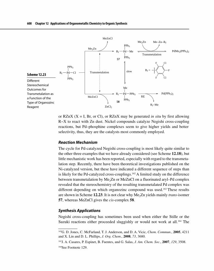
608 Chapter 12 Applications of Organometallic Chemistry to Organic Synthesis
or RZnX (X = I, Br, or Cl), or RZnX may be generated in situ by first allowing R−X to react with Zn dust. Nickel compounds catalyze Negishi cross-coupling reactions, but Pd–phosphine complexes seem to give higher yields and better selectivity, thus, they are the catalysts most commonly employed.
Reaction MechanismThe cycle for Pd-catalyzed Negishi cross-coupling is most likely quite similar to the other three examples that we have already considered (see Scheme 12.18), but little mechanistic work has been reported, especially with regard to the transmeta-lation step. Recently, there have been theoretical investigations published on the Ni-catalyzed version, but these have indicated a different sequence of steps than is likely for the Pd-catalyzed cross-couplings.162 A limited study on the difference between transmetalation by Me2Zn or MeZnCl on a fluorinated aryl–Pd complex revealed that the stereochemistry of the resulting transmetalated Pd complex was different depending on which organozinc compound was used.163 These results are shown in Scheme 12.23. It is not clear why Me2Zn yields mainly trans-isomer 57, whereas MeZnCl gives the cis-complex 58.
Synthesis ApplicationsNegishi cross-coupling has sometimes been used when either the Stille or the Suzuki reactions either proceeded sluggishly or would not work at all.164 The
162G. D. Jones, C. McFarland, T. J. Anderson, and D. A. Vicic, Chem. Commun., 2005, 4211 and X. Lin and D. L. Phillips, J. Org. Chem., 2008, 73, 3680.163J. A. Casares, P. Espinet, B. Fuentes, and G. Salas, J. Am. Chem. Soc., 2007, 129, 3508.164See Footnote 129.
Scheme 12.23 Different Stereochemical Outcomes for Transmetalation as a Function of the Type of Organozinc Reagent
PPh3
Pd
PPh3
ClRf
PPh3
Pd
PPh3
MeRf
Me
Pd
PPh3
PPh3Rf
Me2Zn
MeZnCl
Me2Zn Me−Zn−Rf
PdMe2(PPh3)2
slow
Pd(PPh3)2
57
58
Rf =
F Cl
F
ClF
Rf−Me
Transmetalation
RE
Transmetalation
ZnCl2
MeZnCl

12-4 Carbon–Carbon Bond Formation via Transmetalation Reactions (Cross-Coupling Reactions) 609
reaction, however, is often less tolerant of acidic or carbonyl-containing func-tional groups already present on R and R′. Organozinc reagents are also sensitive to oxygen and moisture, which is not too surprising because Zn is more electro-positive than either B or Sn. Equations 12.80–12.82 hint at the utility of Negishi cross-coupling.
N F
Br1) BuLi
2) ZnCl2N F
ClZn
Pd(PPh3)4
THF/65 oC
NO
O
OTf+
NO
O
N
F
5960
(77% yield)
12.80
O
PPh2 PPh2
Bis(2-(diphenylphosphino)phenyl) Ether (DPE-Phos)
Ph ZnCl + PhCH2−XPdCl2(DPE-phos)
X = Cl, Br
Ph CH2−Ph
(89-96% yield)THF/23 oC
61
12.81
N
I
Boc
Zn
N
ZnI
Boc
N Br
[Pd2(dba)3]P(2-furyl)3
THF/25 oC
N
NBoc
6263
(63% yield)
12.82
Equation 12.80 shows a vinyl–aryl cross-coupling, which is apparently toler-ant of the vinyl carbamate group on compound 59. The organozinc reagent (60)

610 Chapter 12 Applications of Organometallic Chemistry to Organic Synthesis
was prepared by first treatment of 5-bromo-2-fluoropyridine with BuLi to give the corresponding 5-lithiopyridine, which then was allowed to react with ZnCl2 to produce 60 (a typical procedure for making aryl and vinylzinc compounds).165 An alkynylzinc reagent combines with benzyl bromide in equation 12.81 to yield coupled product.166 The best precatalyst for this transformation was the com-plex Pd(DPE–phos)Cl2 (61), which was far superior to Pd(dppf)Cl2—a normally very effective, general catalyst for stubborn cross-couplings. A highly strained alkyl iodide (62) reacts with Zn dust in equation 12.82 to give the corresponding organozinc reagent. Cross-coupling with 2-bromopyridine, catalyzed by Pd[P(2-furyl)3]2, yields the N-protected pyridylazetidine 63.167
Scheme 12.24 highlights a spectacular cascade of transmetalations that begins with Zr-catalyzed formation of alkynylalane 64, followed by transmeta-lation to the corresponding organozinc reagent, which then undergoes Negishi cross-coupling with a vinyl bromide. The resulting product 65 was deprotected to give terminal alkyne 66, then the transmetalation cascade was repeated, and the final step was a bis-Negishi cross-coupling to yield β-carotene (67). The overall yield going from the starting point in the scheme to β-carotene was 48%, truly a remarkable example of the power of the Negishi reaction and a nice demonstra-tion of a Zr → Al → Zn → Pd transmetalation cascade.168
Further DevelopmentsResearch is active to produce precatalysts that are stable in air, highly active, well-defined, and possess a broad spectrum of activity. One such precatalyst is complex 68, which consists of Pd complexed with a sterically hindered NHC carbene (Section 10-1-1). Also present is a substituted pyridine ligand (a so-called “throw-away” ligand). Complex 68 is a member of the PEPPSI (pyridine- enhanced precatalyst preparation, stabilization, and intitiation) family
165A. Sutherland, T. Gallagher, C. G. V. Sharples, and S. Wonnacott, J. Org. Chem., 2003, 68, 2475.166M. Qian and E. Negishi, Tetrahedron Lett., 2005, 46, 2927.167S. Billotte, Synlett, 1998, 379.168F. Zeng and E. Negishi, Org. Lett., 2001, 3, 719.
Exercise 12-15 Propose a mechanism for Zr-catalyzed methyl-alumination of the terminal alkyne starting material in Scheme 12.24. Your mechanism should account for the stereochemistry of the transformation.

12-4 Carbon–Carbon Bond Formation via Transmetalation Reactions (Cross-Coupling Reactions) 611
(“generation”) of precatalysts. This particular precatalyst is active in promoting Negishi cross-coupling between a wide variety of aryl and alkyl groups (R′ = aryl or alkyl; R = aryl or alkyl).169 PEPPSI catalysts have also shown activity for Suzuki cross-coupling,170 so their versatility will no doubt increase over the years.
169M. G. Organ, S. Avola, I. Dubovyk, N. Hadei, E. A. B. Kantchev, C. J. O’Brien, and C. Valente, Chem. Eur. J., 2006, 12, 4749.170C. J. O’Brien, E. A. B. Kantchev, C. Valente, N. Hadei, G. A. Chass, A. Lough, A. C. Hopkinson, and M. G. Organ, Chem. Eur. J., 2006, 12, 4743.
Scheme 12.24 Cascading Transmetalations and Negishi Cross-Coupling Used in the Synthesis of β-Carotene
Me
MeMe
AlMe3/Cp2ZrCl2
CH2Cl2/23 oCMe
MeMe
AlMe2
Me
SiMe3
Br
ZnCl2
Me
MeMe
ZnCl
Me
[Pd2(dba)3]/P(2-furyl)3
DMF/23 oCMe
MeMeMe R
R = SiMe3 (65)
AlMe3/Cp2ZrCl2CH2Cl2/23 oC
Me
MeMeMe Me
AlMe2
1) ZnCl2
2) BrI
[Pd2(dba)3]/P(2-furyl)3
DMF/23 oC
Me
MeMeMe Me
Me MeMe Me
Me
64
67
(48% yield overall)
R = H (66)
Deprotection

612 Chapter 12 Applications of Organometallic Chemistry to Organic Synthesis
Pd ClCl
N
Cl
NN
68
It is now possible to couple chlorophenols, haloanilines, and halovinyl alco-hols with organozinc reagents without concern that protic groups found in R′−X will react with the transmetalating agent. Equation 12.83 outlines this procedure, which also shows another variation in the synthesis of organozinc compounds—direct insertion of Zn into a C−X bond in the presence of LiCl.171
Cl
ZnCl-LiCl Pd(OAc)2
SPhos (69)THF/25 oC
Cl
Br
OH
O
H+
OH
O
H
(81% yield)
OMeMeO
PCy2
69
12.83
A key to the success of this transformation is the use of a relatively new ligand for Pd called SPhos (69), which Buchwald found especially useful for speeding up normally sluggish cross-coupling reactions.172
The discovery, use, and further development of cross-coupling reactions have mightily advanced the field of organic synthesis. Today, chemists routinely use Stille, Suzuki, Sonogashira, and Negishi reactions to construct new C−C bonds, and this step is often the key to successful synthesis of incredibly complex
171G. Manolikakes, M. A. Schade, C. M. Hernandez, H. Mayr, and P. Knochel, Org. Lett., 2008, 10, 2765.172S. D. Walker, T. E. Barder, J. R. Martinelli, and S. L. Buchwald, Angew. Chem. Int. Ed., 2004, 43, 1871.

12-5 Carbon–Carbon Bond Formation through Cyclization Reactions 613
molecules. It is clear that investigations on the utility of cross-coupling reactions will continue to be an active area of research for many years to come.
12-5 CARBON–CARBON BOND FORMATION THROUGH CYCLIZATION REACTIONSPreviously in Chapter 12 we have seen several examples of cyclization reactions that have involved transition metal catalysis. In Chapter 11, we introduced Mo- and Ru-catalyzed RCM as a means of converting acyclic dienes, alkene–alkynes, and dialkynes into rings containing carbon–carbon double and triple bonds. Section 12-5 will cover a few cases where organotransition metal complexes effectively promote the construction of rings where two or more C−C bond connections occur during the same transformation. Some examples will be extensions of reac-tions already covered, whereas others will entail “new” chemistry.
12-5-1 Cyclizations Involving Fischer Carbene Complexes: The Dötz Arene SynthesisFischer chromium carbene complexes have numerous applications to organic synthesis. Beginning about 25 years ago, Dötz,173 Wulff,174 and several other groups discovered and developed a procedure for synthesizing substituted phe-nols, naphthols, and higher polycyclic aromatic homologs that amounts to a [3 + 2 + 1] cyclization involving three partners: a Cr –carbene complex (contributing three of the ring atoms), an alkyne (contributing two ring atoms), and CO (con-tributing the sixth ring atom). Equation 12.84 shows a schematic representation of the cyclization, indicating how the reactant fragments fit together. Note that the methoxy group attached to Ccarbene ends up para to the phenolic OH group. If the alkyne is unsymmetrically substituted, the larger substituent usually ends up ortho to the phenolic OH.175
C C
COMe
Cr(CO)5
C C R'''R''
R' R
O C O
R' R
R'''R''
OMe
H
HO OMe
R' R
R'''R''
1
2 3
4
56
12.84
173For a summary of work on the use of Cr carbenes to synthesize arenes, see K. H. Dötz, Angew. Chem. Int. Ed. Engl., 1984, 23, 587.174W. D. Wulff, P.-C. Tang, K.-S., Chan, J. S. McCullum, D. C. Yang, and S. R. Gilbertson, Tetrahedron, 1985, 41, 5813.175Electronic effects also play a role in directing regiochemistry. Electron-withdrawing sub-stituents tend to end up ortho to the phenol group, whereas electron-donating groups (such as ethers) prefer the meta position. See F. J. McQuillan, D. J. Parker, and G. R. Stephenson, Transition Metal Organics for Organic Synthesis, Cambridge University Press: Cambridge, 1991, pp. 419–420.

614 Chapter 12 Applications of Organometallic Chemistry to Organic Synthesis
Scheme 12.25 shows the generally accepted mechanism for the cyclization. First, carbene complex 70 loses one CO ligand, which provides an open coordi-nation site for the incoming alkyne and formation of 71 (overall a dissociative ligand substitution, which is considered the rate-determining step).176 An early proposal for the next step suggested that rearrangement of 71 would lead to chro-macyclobutene 72, a reaction that should be familiar from Chapters 10 and 11. Calculations indicated, however, that this was not likely,177 and instead direct
176H. Fischer and P. Hofmann, Organometallics, 1999, 18, 2590, and references therein.177P. Hofmann and M. Hämmerle, Angew. Chem. Int. Ed. Engl, 1989, 28, 908; for an examination of the entire mechanism of the Dötz reaction at the DFT level of theory, see
Scheme 12.25 Mechanism of the Dötz Reaction
CC
C
OMe
Cr
R'R
C
C
H
C
C
OC
O
O
O
O CO
CC
C
OMe
Cr
R'R
C
C
H
C
OC
OO
O
CC
C
OMe
Cr
R'R
C
C
H
C
OC
OO
OC C RSRL
C C RSRL
(CO)4Cr
RSRL
R'R
OMeMigratory
CO insertion
C
RSRL
R'R
OMeO
Cr(CO)3
C
RSRL
R'R
OMeO
Cr(CO)3
H
C
RSRL
R'R
OMeHO
Cr(CO)3
(NH4)2Ce(NO3)6C
RSRL
R'R
OMeHO
Keto-enol tautomerism
70 71
Migratory1,2-alkyneinsertion
(CO)4Cr
RSRL
OMe
R'R72
737475
76 77
RL = larger substituentRS = smaller substituent
Ligand substitution
Electrocyclicring closing
Oxidative decomplexation

12-5 Carbon–Carbon Bond Formation through Cyclization Reactions 615
insertion of the alkyne between Cr and Ccarbene occurs to yield 73. Next, migratory CO insertion occurs to produce ketene 74, which is followed by electrocyclic ring closure to give cyclohexadienone complex 75.178 The driving force for the reaction, regardless of prior mechanistic steps, is the highly exothermic and rapid keto–enol tautomerism to yield phenol–Cr complex 76.179 Several methods exist to remove the metal from the η6–π ligand of 76 to produce highly substituted aromatic compound 77. These include oxidative treatment with air or Ce(IV) and carbonylation of Cr in an atmosphere of CO.180
For unsymmetrical alkynes, there are two orientations possible for the alkyne substituents in the final six-membered ring product. Assume that 1-hexyne reacts with (CO)5Cr=C(OMe)(Ph) to give a naphthol derivative. Follow the reaction through according to Scheme 12.25 and determine the predominant regioisomer based upon the difference in steric hindrance of the substituents attached to the triple bond of the alkyne.
Exercise 12-16
The Dötz arene synthesis is an excellent technique for construction of complex, densely functionalized aromatic ring systems. Equations 12.85–12.87 present three examples.
(CO)5Cr
OMe
+ Ph
1) THF/45 oC
2) Ac2O/Et3N THF/60 oC
HO OMe
Ph
(93% yield)
12.85
M. M. Gleichmann, K. H. Dötz, and B. A. Hess, J. Am. Chem. Soc., 1996, 118, 10551. For a recent theoretical investigation of the Dötz reaction, which supports earlier work, see S. Ketrat, S. Müller, and M. Dolg, J. Phys. Chem. A, 2007, 111, 6094.178For additional information on electrocyclic ring openings and closures, see P. Y. Bruice, Organic Chemistry, 5th ed., Pearson/Prentice Hall: Upper Saddle River, NJ, 2007, pp. 1269–1275 and F.A. Carey and R.J. Sundberg, Advanced Organic Chemistry, Part A, 5th ed., Springer Scientific: New York, 2007, Chap. 10, especially pp. 892–911.179Keto–enol tautomerism will not occur if there are two substituents at C-6.180For a good summary of mechanistic investigations on the Dötz reaction, see A. de Meijere, H. Schirmer, and M. Duetsch, Angew. Chem. Int. Ed., 2000, 39, 3964, and refer-ences therein; see also M. L. Waters, M. E. Bos, and W. D. Wulff, J. Am. Chem. Soc., 1999, 121, 6403.

616 Chapter 12 Applications of Organometallic Chemistry to Organic Synthesis
N
Me
Me
OMe
Cr(CO)5
+ Prhexane/50 oC
N
Me
Me
O
OMe
Pr
(85% yield) 12.86
Cr(CO)5MeO
+
O
OTBDPS
TBDPSO
OTBDPS
1) THF/55 oC
2) air exposure/30 min3) Ac2O/pyridine/ DMAP/CH2CH2
O
OTBDPS
TBDPSO
OTBDPS
OMe
OAc
(62% yield)
12.87
Equation 12.85181 shows a benzoannulation to produce a substituted naphthalene in very good yield. The phenol is acetylated in the same reaction vessel, and apparently the reaction conditions, including the presence of acetic anhydride and Et3N, cause the chromium carbonyl fragment to depart. Formation of a sub-stituted indole occurs in equation 12.86.182 Because a methyl group resides at the 3-position on the indole–carbene complex, the keto form is the end product. A naphthyl glycoside results in the reaction shown by equation 12.87, which also demonstrates that monosaccharide units survive typical Dötz reaction conditions. Again, the phenolic group is intercepted by acetic anhydride to form the phenyl acetate product. Exposure to air is used for decomplexation.183
12-5-2 Cyclizations Involving PalladiumDiscovered over 60 years ago184 and analogous to the renowned Diels–Alder reac-tion, the ene reaction (equation 12.88) is a concerted transformation that brings together two partners, one of which is a simple π system, called the ene (typically an isolated C=C or C=O bond with at least one hydrogen at the allylic position) and the other an isolated π bond, termed the enophile (enophiles with electron-withdrawing groups attached to the π system work best). The reaction resembles a cycloaddition, proceeding through a six-electron, six-membered-ring transition state (78), and both intra- and intermolecular versions are known. Because the reaction
181J. Bao, W. D. Wulff, et al., J. Am. Chem. Soc., 1996, 118, 3392.182W. E. Bauta, W. D. Wulff, S. F. Pavkovic, and E. J. Zaluzec, J. Org. Chem., 1989, 54, 3249.183S. R. Pulley and J. P. Carey, J. Org. Chem., 1998, 63, 5275.184K. Alder, F. Pascher, and A. Schmitz, Chem. Ber., 1943, 76, 27.

12-5 Carbon–Carbon Bond Formation through Cyclization Reactions 617
results in the formation of a new C−C bond with the stereoselectivity attendant con-certed processes, the ene reaction has great potential as a useful synthetic procedure. Intramolecular versions, moreover, produce rings. The utility of the transformation was limited for many years, however, because of the high temperatures required compared with those used for its more famous analog, the Diels–Alder reaction.
H
R2
R1
+
R3
∆H
R2
R3R1
78
H
R1
R2
R3
12.88
The discovery that Lewis acids catalyze ene reactions greatly increased the utility of the transformation.185 Equations 12.89186 and 12.90187 demonstrate the effect of a Lewis acid, ZnBr2, in not only decreasing the severity of reactions conditions required, but also increasing the stereoselectivity observed.
HEtO2C
CO2Et
Me
255 oC
Me
CO2Et
EtO2C
Me
CO2Et
EtO2C
+
(13 : 87)
12.89
HEtO2C
CO2Et
Me
25 oC
Me
CO2Et
EtO2C
Me
CO2Et
EtO2C+
ZnBr2
Me Me Me
(97 : 3)
12.90
Palladium is effective as a catalyst for the ene reaction. Two research groups, Trost’s188 in the United States and Oppolzer’s189 in Switzerland, used slightly different approaches to synthesize five-membered rings via a Pd-catalyzed ene reaction. Scheme 12.26 shows an example of Trost’s procedure. The starting
185For a review of acid-catalyzed ene reactions, see B. B. Snider, Acc. Chem. Res., 1980, 13, 426.186S. K. Ghosh and T. K. Sarkar, Tetrahedron Lett., 1986, 27, 525.187L. F. Tietze, V. Beifuss, and M. Ruther, J. Org. Chem., 1989, 54, 3120.188B. M. Trost, Acc. Chem. Res., 1990, 23, 34, and references therein.189W. Oppolzer, Angew. Chem. Int. Ed. Engl., 1989, 28, 38.

618 Chapter 12 Applications of Organometallic Chemistry to Organic Synthesis
material for the ene reaction is a 1,6-enyne (80), which results from a nice application of chemistry we have already seen—attack of a stabilized carban-ion on a Pd–allyl complex (79) (the Tsuji–Trost reaction, Section 12-2). Once formed, 80 undergoes the ene reaction in the presence of Pd(II) to give 81.
Research on the mechanism of the Pd(II)-catalyzed ene reaction points to a hydropalladation cycle shown in Scheme 12.27, which first involves compl-exation of Pd to both π ligands of the substrate to yield 82 (step a). Migratory 1,2-insertion of the alkyne into the Pd−H bond provides 83 (step b), and then 1,2-insertion of the η2-coordinated double bond occurs to yield 84 (step c). Finally, step d is β-elimination, which yields two possible regioisomers (85 and 86).
Several applications of the Trost ene reaction have appeared in the litera-ture. A spectacular extension of this reaction involves a cascade of reactions, first using the ene reaction to construct a five-membered ring and then utilizing the remaining functionality to initiate a subsequent ene reaction followed by an elec-trocyclic ring closure.190 Scheme 12.28 describes this transformation in which an acyclic molecule is transformed in one operation into a tricyclic species.
190B. M. Trost and Y. Shi, J. Am. Chem. Soc., 1992, 114, 791.
Scheme 12.26 Trost’s Pd-Catalyzed Ene Reaction
OAc
CO2Me
LnPd
CO2Me
PdL2
OAc−MeO2C
CO2Me
CO2Me
HH
H
Pd(II)PhH/66 oC
CO2Me
CO2Me
CO2Me
H
H
(85% yield)
79 80
81
CO2Me
CO2Me
Exercise 12-17 The reaction below is another impressive example of cascading intramolecular ene reactions. Show how the transformation occurs by writing down all the intermediates formed after each ene reaction.
OMe
R
R
MeO
RR
[Pd2(dba)3]
PPh3/HOAc
R = SO2Ph

12-5 Carbon–Carbon Bond Formation through Cyclization Reactions 619
Oppolzer’s approach to Pd-catalyzed ene reactions starts with an allyl acetate that is part of a 1,6-diene system. Scheme 12.29 details a plausible mechanism that involves a Pd(0) species as the active catalyst. The cycle begins with oxida-tive addition of the allyl acetate portion of 87 to give 88. Next, η1– to η3–allylic rearrangement leads to 89, and allylic rearrangement again gives 90. Insertion of a 1,2-C=C bond follows, yielding 91. The last step, as in the Trost procedure, is β-elimination.
Equation 12.91 shows an application of Oppolzer’s approach in which two five-membered rings result from consecutive ene reactions.191
191W. Oppolzer and R. J. DeVita, J. Org. Chem., 1991, 56, 6256. Oppolzer has also used Rh(I) complexes to catalyze the ene reaction. Yields are similar, but the stereochemical results are opposite those obtained with Pd catalysts. This difference may be a function of the octahe-dral geometry of Rh(III) intermediates, presumably generated during the catalytic cycle. See W. Oppolzer and A. Fürstner, Helv. Chim. Acta., 1993, 76, 2339.
Scheme 12.27 The Hydropalladation Mechanism for the Ene Reaction
Pd(OAc)2
H−Pd−X
H
H
H
H
PdX
H
H
H
Pd X
H
Pd X
H
H
HX
X = OAc− or halogen
H
H
+
a
bc
d
85 86
82
83
84

620 Chapter 12 Applications of Organometallic Chemistry to Organic Synthesis
Scheme 12.28 Pd-Catalyzed Ene Cascade of Cyclization Reactions
Me
Me
TBDMSO
R
R'
E E HPdX
PPh 3
PdX
R'
R
H
Me
Me
TBDMSO
E
E
Complexation and hydropalladatio n
R
Me
Me PdX
R'
E
E
TBDMSO
R'
R
TBDMSO
Me
Me
E E
R
R' Me
Me
E E
TBDMSO
(57-70% yield)
E = CO 2 Me R = H, E R' = H, Ph
1,2-Insertio n
1) 1,2-Insertion
2) β-Elimination
Electrocyclic ring closur e
OAc
CO2Me
CO2Me
MeO2C
MeO2C
H
HH
H
HMe
MeO2C
MeO2C CO2Me
CO2Me
(70% yield)
(PPh3)4Pd
12.91
An Oppolzer cyclization was used in the stereoselective synthesis of (−)-eryth-rodiene (95), a sesquiterpenoid isolated from Caribbean coral (Scheme 12.30).192
192W. Oppolzer and F. Flaschmann, Tetrahedron Lett., 1998, 39, 5019.

12-5 Carbon–Carbon Bond Formation through Cyclization Reactions 621
An interesting twist here is to use a stoichiometric excess of Et2Zn to transmeta-late the η3–allyl–Pd intermediate 92, which can then react with a variety of elec-trophiles (see Section 8-4). In this case, iodination of dialkylzinc compound 93 yields alkyl halide 94, which is nicely set up to give only one E2 elimination product—(−)-erythrodiene. The use of Et2Zn allowed Oppolzer to run the metal–ene cyclization at a low temperature.
Equation 12.92 highlights a recent example of Trost metal–ene cycliza-tion where enyne 96 yielded azacyclopentane 97.193 The addition of a catalytic amount of an acetylated amino acid (N-acetylphenylalanine) provides just the right amount of acidity to speed up the reaction. If the reaction occurs in the presence of a secondary amine, the ketone that initially forms from the cycliza-tion becomes an enamine. Subsequent hydrogenation over the Pd catalyst already present produces amine 98.
193C. J. Kressierer and T. J. J. Müller, Org. Lett., 2005, 7, 2237.
Scheme 12.29 Oppolzer’s Pd-Catalyzed Ene Reaction
H−Pd−OAc Pd(0)
AcO−Pd
Pd
OAc
Pd
OAc
H
PdOAc
HOAc
AcO
87
88
8990
91
η1 to η3
Rearrangement
η3 to η1
Rearrangement
1,2-Insertion
β-Elimination
REOA

622 Chapter 12 Applications of Organometallic Chemistry to Organic Synthesis
TsN
OH
SiMe3 [Pd2(dba)3]-CHCl3
N-Ac-phenylalanineCH2Cl2/25 oC
TsN
SiMe3
OH
TsN
SiMe3
O
NH
TsN
SiMe3
N
(96% yield)
(76% yield)
96 97
98
1)
2) H2 (1 bar)/Pd(0)
Scheme 12.30 Use of the Oppolzer Metal–Ene Reaction for the Synthesis of (−)-Erythrodiene
OAc
LnPd(0)
PdLn
Et2Zn
ZnEt
H
ZnEt
I2
H
I
KOt-Bu
DMSO
(−)-erythrodiene
92 93
9495+ EtZnI
Exercise 12-18 Propose a mechanism to explain how the metal–ene cyclization followed by reaction with piperidine and subsequent hydrogenation, shown in equation 12.92, produced amine 98.
12.92
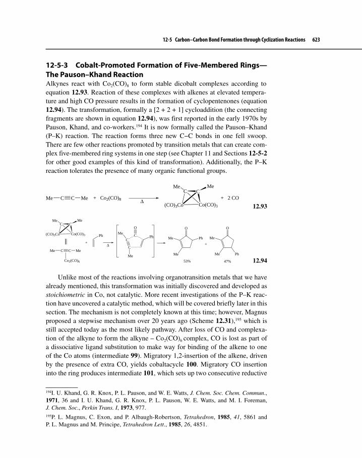
12-5 Carbon–Carbon Bond Formation through Cyclization Reactions 623
12-5-3 Cobalt-Promoted Formation of Five-Membered Rings—The Pauson–Khand ReactionAlkynes react with Co2(CO)8 to form stable dicobalt complexes according to equation 12.93. Reaction of these complexes with alkenes at elevated tempera-ture and high CO pressure results in the formation of cyclopentenones (equation 12.94). The transformation, formally a [2 + 2 + 1] cycloaddition (the connecting fragments are shown in equation 12.94), was first reported in the early 1970s by Pauson, Khand, and co-workers.194 It is now formally called the Pauson–Khand (P–K) reaction. The reaction forms three new C−C bonds in one fell swoop. There are few other reactions promoted by transition metals that can create com-plex five-membered ring systems in one step (see Chapter 11 and Sections 12-5-2 for other good examples of this kind of transformation). Additionally, the P–K reaction tolerates the presence of many organic functional groups.
C
Co(CO)3
C CMe Me + Co2(CO)8 ∆(CO)3Co
CMeMe
+ 2 CO
12.93
C
Co(CO)3(CO)3Co
CMeMe
Co2(CO)6
C C MeMe
+
Ph
∆ C
CC
O
PhMe
Me
Me
Me
Ph
O
Me
Me
O
Ph
+
53% 47%
12.94
Unlike most of the reactions involving organotransition metals that we have already mentioned, this transformation was initially discovered and developed as stoichiometric in Co, not catalytic. More recent investigations of the P–K reac-tion have uncovered a catalytic method, which will be covered briefly later in this section. The mechanism is not completely known at this time; however, Magnus proposed a stepwise mechanism over 20 years ago (Scheme 12.31),195 which is still accepted today as the most likely pathway. After loss of CO and complexa-tion of the alkyne to form the alkyne – Co2(CO)6
complex, CO is lost as part of a dissociative ligand substitution to make way for binding of the alkene to one of the Co atoms (intermediate 99). Migratory 1,2-insertion of the alkene, driven by the presence of extra CO, yields cobaltacycle 100. Migratory CO insertion into the ring produces intermediate 101, which sets up two consecutive reductive
194I. U. Khand, G. R. Knox, P. L. Pauson, and W. E. Watts, J. Chem. Soc. Chem. Commun., 1971, 36 and I. U. Khand, G. R. Knox, P. L. Pauson, W. E. Watts, and M. I. Foreman, J. Chem. Soc., Perkin Trans. I, 1973, 977.195P. L. Magnus, C. Exon, and P. Albaugh-Robertson, Tetrahedron, 1985, 41, 5861 and P. L. Magnus and M. Principe, Tetrahedron Lett., 1985, 26, 4851.

624 Chapter 12 Applications of Organometallic Chemistry to Organic Synthesis
eliminations to finally give cyclopentenone 102. Finally, it should be noted that although the P–K reaction occurs primarily at only one of the two Co atoms, the other cobalt carbonyl fragment seems to serve as an anchor to stabilize the reactions occurring at the reactive Co center.196
Theoretical studies demonstrated that the Magnus mechanism is a reasonable pathway, and they further indicated that the loss of CO before alkene complexa-tion, as is the case with the Dötz cyclization, is probably the rate-determining step. Calculations showed that 1,2-alkene insertion also has a relatively high energy barrier, is irreversible, and may be rate limiting in some cases.197 It is this step that determines both the regio- and the stereoselectivity of the alkene fragment in the cyclopentenone. Special mass spectrometric techniques have observed in the gas phase some of the intermediates postulated by Magnus.198
The P–K reaction is regioselective for cycloaddition of substituted alkynes, yielding a cyclopentenone in which the larger alkyne substituent is usually adjacent to the keto group. Stereochemistry about 1,2-disubstituted alkenes is typically preserved upon cycloaddition; however, if the substituents are differ-ent, both regioisomers will form. The reaction is quite sensitive to the nature of the alkene. Tri- and tetra-substituted olefins are unreactive, and the order of
196For a good review of the mechanism of the P–K reaction, see S. Laschat, A. Becheanu, T. Bell, and A. Baro, Synlett, 2005, 2547.197(a) M. Yamanaka and E. Nakamura, J. Am. Chem. Soc., 2001, 123, 1703 and (b) T. J. M. de Bruin, A. Millet, A. E. Greene, and Y. Gimbert, J. Org. Chem., 2004, 69, 1075.198Y. Gimbert, D. Lesage, A. Milet, F. Fournier, A. E. Greene, and J.-C. Tabet, Org. Lett., 2003, 5, 4073.
Scheme 12.31 Mechanism of the Pauson–Khand Reaction
Co(CO)3(CO)3Co
RL
RS CO
R'
Co(CO)3(CO)2Co
RL
RSR'
Co(CO)3(CO)3Co
RL
RSR'
CO
Co(CO)3(CO)3Co
RL
RS
R'
Co(CO)3
Co(CO)3
RL
RS
O
R'
O RL
RSR'
Dissociative ligand substitution
Migratory1,2- insertion
MigratoryCO insertion
RERE
99 100
101102
O
CO

12-5 Carbon–Carbon Bond Formation through Cyclization Reactions 625
reactivity for cycloalkenes is the following: cyclohexene < cyclopentene < nor-bornene (bicylo[2.2.1]hept-2-ene); cyclopropenes are also reactive.199
The first examples of the P–K reaction required high temperatures and pres-sures to succeed. Several improvements in yield and reaction rate have resulted from continued research efforts over the past 30 years. These include the addition of silica gel200 to the reaction mixture (adsorption of the alkyne–Co complex onto silica may restrict molecular motion, allowing the ene–yne system to interact more readily; also, lack of solvent would allow bimolecular reactions to proceed faster); the use of tertiary amine N-oxides;201,202 the application of photochemical conditions to ease departure of CO in the rate-determining step; and the inclusion of various Lewis bases, which help stabilize intermediate Co complexes.203
Despite various improvements and enhancements, the intermolecular P–K reaction suffers from a number of problems including relatively harsh reaction conditions, poor regioselectivity at the alkene region of the five-membered ring, and diversion of product into side reactions.204 The intramolecular version of the P–K reaction is much more useful as a means of five-membered ring synthe-sis for several reasons: (1) the problem of regiochemistry is eliminated because only one orientation of the alkene with respect to the alkyne–Co complex is possible; (2) both reactants are positioned in the same molecule, so unfavorable entropy effects are diminished and the need for high concentrations of reactants is removed; (3) stereochemistry in the alkene region of the new ring is easier to
199There is a correlation between the energy of the LUMO of the alkene (the π* orbital) and its reactivity. The lower the LUMO energy, the faster the reaction. When a LUMO is low in energy, it is easier for Co to back-donate some of its electron density into the π* orbital of the alkene. This means less electron density that is available for back-donation to the CO ligands. The CO ligands are thus less tightly bound to Co, which means they come off the metal more rapidly as needed and the overall reaction speeds up. See Footnote 197b for more explanation.200S. O. Simonian, W.A. Smit, A. S. Gybin, A. S. Shashkov. G. S. Mikaelian, V. A. Tarasov, I. I. Ibragimov, R. Caple, and D. E. Froen, Tetrahedron Lett., 1986, 27, 1245.201S. Shambayani, W. E. Crowe, and S. L. Schreiber, Tetrahedron Lett., 1990, 31, 5289.202Remember that N-oxides remove CO ligands by formation of CO2 (Section 8-3); this probably opens a site on Co for complexation of the alkene fragment. More recent advances here include tethering the amine N-oxide onto a polymer support, which obviates the neces-sity of using 3-6 equivalents of amine N-oxide in solution. See W. J. Kerr, D. M. Lindsay, and S. P. Watson, Chem. Commun., 1999, 2551.203For good reviews on recent advances in improving the efficacy of intermolecular P–K reactions, see Footnote 196 and S. E. Gibson and N. Mainolfi, Angew. Chem. Int. Ed., 2005, 44, 3022.204For a review focusing on P–K side reactions, see L. V. R. Boñaga and M. E. Krafft, Tetrahedron, 2004, 60, 9795.
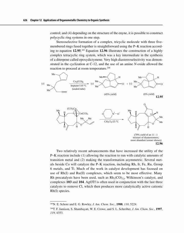
626 Chapter 12 Applications of Organometallic Chemistry to Organic Synthesis
control; and (4) depending on the structure of the enyne, it is possible to construct polycyclic ring systems in one step.
Stereoselective formation of a complex, tricyclic molecule with three five-membered rings fused together is straightforward using the P–K reaction accord-ing to equation 12.95.205 Equation 12.96 illustrates the construction of a highly complex tetracyclic ring system, which was a key intermediate in the synthesis of a diterpene called epoxydictymene. Very high diastereoselectivity was demon-strated in the cyclization at C-12, and the use of an amine N-oxide allowed the reaction to proceed at room temperature.206
Me
Me
Me
Co2(CO)8
heptane/110 oC(sealed tube)
OMe
Me
H
OMe
Me
H
+
(45% yield) (6% yield)
Me Me
( ) (±) (±)±
Co(CO)3
(CO)3Co
O
Me Me
MeH
H H
NO O
CH2Cl2/25 oCO
Me H
H
O
Me
Me
H
H12
(70% yield of an 11 : 1mixture of diastereomers;
more abundant isomer shown)
12.96
Two relatively recent advancements that have increased the utility of the P–K reaction include (1) allowing the reaction to run with catalytic amounts of transition metal and (2) making the transformation asymmetric. Several met-als beside Co will catalyze the P–K reaction, including Rh, Ir, Fe, Ru, Group 6 metals, and Ti. Much of the work in catalyst development has focused on use of Rh(I) and Ru(II) complexes, which seem to be most effective. Many Rh precatalysts have been used, such as Rh3(CO)12, Wilkinson’s catalyst, and complexes 103 and 104. AgOTf is often used in conjunction with the last three catalysts to remove Cl, which then produces more catalytically active cationic Rh(I) species.
205N. E. Schore and E. G. Rowley, J. Am. Chem. Soc., 1988, 110, 5224.206T. F. Jamison, S. Shambayati, W. E. Crowe, and S. L. Schreiber, J. Am. Chem. Soc., 1997, 119, 4353.
12.95

12-5 Carbon–Carbon Bond Formation through Cyclization Reactions 627
RhC
Cl P
P
PhPh
Ph Ph
O
103
RhCl PPh2
C
RhPPh2
Cl PPh2
C
Ph2P O
O
104
Equation 12.97 illustrates use of catalyst 104 in the synthesis of a bicyclic ring system.207 Note that the presence of a catalyst also allows the transforma-tion to occur under a CO pressure of 1 bar. Equation 12.98 demonstrates a clever application of the so-called “traceless tether” method for running a Ru-catalyzed P–K reaction.208 Although this is an intermolecular P–K reaction, the alkene is tethered to a pyridylsilyl group (compound 105), which directs regioselective reaction of the alkene fragment with the alkyne. The presence of residual H2O in the reaction mixture removes the silyl group, which can be recycled.
PhEtO2C
EtO2C
CO (1 bar)
104 (cat.)/PhMe/110 oC
EtO2C
EtO2CO
Ph
(99% yield)
N
SiMe2
Ph
1) CO (1 atm)
2)
O
Ph
Me
Me
(75% yield)105
Ru3(CO)12/100 ºC
12.98
Chemists have investigated asymmetric P–K reactions, using chiral diphos-phine and diphosphite ligands to induce enantioselectivity. When (S)-BINAP was added to a catalytic amount of Co4(CO)12, (S)-bicyclic ketone 106 formed in 55% yield with an ee of 88% (equation 12.99). Experimental evidence suggested that the active catalyst was dicobalt complex 107, in which BINAP binds in bidentate
207N. Jeong, B. K. Sung, J. S. Kim, S. B. Park, S. D. Seo, J. Y. Shin, K. Y. In, and Y. K. Choi, Pure Appl. Chem., 2002, 74, 85.208K. Itami, K. Mitsudo, K. Fujita, Y. Ohashi, and J. Yoshida, J. Am. Chem. Soc., 2004, 126, 11058.
12.97

628 Chapter 12 Applications of Organometallic Chemistry to Organic Synthesis
fashion to one of the Co atoms.209 Equation 12.100 shows an asymmetric P–K reaction in which a chiral Ir catalyst (108), based on a modified (R)-BINAP ligand, was used to desymmetrize meso-dienyne 109; the resulting bicycloketone 110 formed with an ee of 96%.210
TsN TsN
H
O
106
Co Co(CO)3
OC
CO
C
PPh2
O
107
Co4(CO)12 (cat.)
(S)-BINAP/CO (1 bar)1,2-dimethoxyethane
75 ºC
(55% yield; 88% ee)
(S)-BINAP
Ph2P
12.99
P
P
OMe
OMe
OMe
OMe
108
[Ir(COD)Cl]2
TsN
Me108 (cat.)/CO (1 bar)
THF/90 oC
109
TsN
H
O
Me
TsN
H
O
Me
+
110
(75% yield; 96% ee)
(75 : 1)
12.100
209S. E. Gibson, K. A. C. Kaufmann, J. A. Loch, and A. Miyazaki, Pure Appl. Chem., 2008, 80, 903.210N. Jeong, D. H. Kim, and J. H. Choi, Chem. Commun., 2004, 1134.

Suggested Readings 629
Chapter 12 serves as an introduction to a huge area of chemistry devoted to the use of organometallic compounds for the construction of complex mol-ecules. The material covered in Chapter 12 exemplifies several of the most important applications of organotransition metal chemistry to organic synthe-sis. Thousands of articles have appeared over the past 10 years that report on either the use of transition metal compounds in key steps of syntheses, which would be difficult or even impossible to carry out without transition metals, or on the development of novel methodology that may have many applications to synthesis down the road. Research on the connection between organometallic chemistry and synthesis remains active and fruitful, and there is every indica-tion that this endeavor will continue to hold the interest of chemists for many years to come.
Suggested Readings
General References on Organometallic SynthesisJ. J. Li and G. W. Gribble, Palladium in Heterocyclic Chemistry, 2nd ed., Elsevier:
Amsterdam, 2007.F. A. Carey and R. J. Sundberg, Advanced Organic Chemistry Part B: Reactions and
Synthesis, 5th ed., Springer: New York, 2007, Chap. 8.C. Elschenbroich, Organometallics, 3rd. ed., Wiley–VCH: Weinheim, Germany, 2006,
Chap. 18.J. Tsuji, Palladium Catalysts and Reagents, Wiley: Chichester, UK, 2004.L. F. Tietze, H. Ila, and H. P. Bell, Chem. Rev., 2004, 104, 3453.M. B. Smith, Organic Synthesis, 2nd ed., McGraw–Hill: New York, 2002, Chap. 12.L. S. Hegedus, Transition Metals in the Synthesis of Complex Organic Molecules, 2nd
ed., University Science Books: Sausalito, CA, 1999.
Enantioselective Functional Group InterconversionsW. S. Knowles and R. Noyori, Acc. Chem. Res., 2007, 40, 1238, and references
therein.J. T. Mohr, D. C. Ebner, and B. M. Stoltz, Org. Biomol. Chem., 2007, 5, 3571.R. Noyori, Chem. Commun., 2005, 1807.B. M. Trost, Proc. Natl. Acad. Sci., USA, 2004, 101, 5348.R. Noyori, Angew. Chem. Int. Ed., 2002, 41, 2008.
Carbon–Carbon Bond Formation via Nucleophilic Attack on a π LigandL. F. Tietze and T. Kinzel, Pure Appl. Chem., 2007, 79, 629.J. T. Mohr and B. M. Stoltz, Chem. Asian J., 2007, 2, 1476.B. M. Trost and M. Crawley, Chem. Rev., 2003, 103, 2921.J. Tsuji, Tetrahedron, 1986, 42, 4361.

630 Chapter 12 Applications of Organometallic Chemistry to Organic Synthesis
Carbon–Carbon Bond Formation via Carbonyl and Alkene InsertionC. Claver, M. Diéguez, O. Pàmies, and S. Castillión, Top. Organomet. Chem., 2006,
18, 35.A. M. Trzeciak and J. J. Ziolkowski, Coord. Chem. Rev., 2005, 249, 2308.A. B. Dounay and L. E. Overman, Chem. Rev., 2003, 103, 2945.
Carbon–Carbon Bond Formation via Transmetalation ReactionsJ. B. Johnson and T. Rovis, Angew. Chem. Int. Ed., 2008, 47, 840.R. Chinchilla and C. Nàjera, Chem. Rev., 2007, 107, 874.E. Negishi, Bull. Chem. Soc. Jpn., 2007, 80, 233.K. C. Nicolaou, P. G. Bulger, and D. Sarlah, Angew. Chem. Int. Ed., 2005, 44, 4442.A. de Meijere and F. Diederich, Eds., Metal-Catalyzed Cross-Coupling Reactions, 2nd
ed., Wiley–VCH: Weinheim, Germany, 2004.S. Kotha, K. Lahiri, and D. Kashinath, Tetrahedron, 2002, 58, 9633.N. Miyaura, Top. Curr. Chem., 2002, 219, 11.
Carbon–Carbon Bond Formation through Cyclization ReactionsD. Strübling and M. Beller, Top. Organomet. Chem., 2006, 18, 165.K. H. Dötz and J. Stendel Jr., “The Chromium-Templated Carbene Benzannulation
Approach to Densely Functionalized Arenes,” In Modern Arene Chemistry, D. Astruc, Ed., Wiley–VCH: Weinheim, Germany, 2002, pp. 250–296.
N.E. Schore, Org. React., 1991, 40, 1.B. M. Trost, Angew. Chem. Int. Ed. Engl, 1989, 28, 1173.
Problems12-1 Calculate the difference in free energies of activation, ∆∆G‡, at 25 °C
for conversion of 7′ to 8′ and 7″ to 8″ that would be required to lead to an enantiomeric excess (ee) of 96% for the R-amino acid ester, 10″ (Scheme 12.3).
12-2 Propose a stepwise mechanism for the following transformation.211
O+
Bu3Sn CO2Me
PdCl2(MeCN)2
DMF/H2O
CO2Me
HO
211J. D. White and M. S. Jensen, Synlett, 1996, 31.

Problems 631
12-3 The equation below shows a very useful method for converting aryl halides to aryl amines (or phenol derivatives). Propose a mechanism for this transformation.212
IMeO + H2N[Pd2(dba)3]/dppf
NaOt-Bu/PhMe80 oC
MeOHN
(HO) (O)
12-4 Consider the first oxidative cyclization shown to produce A. It was pro-posed originally that the cyclization proceeded through η3–allyl–Pd intermediate B. Treatment of C, however, which was predicted to form B under the same reaction conditions, led to A in less than 5% yield, even after 21 hours of reaction time. The researchers involved were forced to come up with another mechanism. Propose an alternate catalytic path-way that involves complexation of the phenolic oxygen and side chain C=C bond to Pd and then oxypalladation of the C=C bond.213
OHPy2Pd(TFA)2/Pyridine
Na2CO3/3A mol. sievesO2/PhMe/80 oC/3 hr
O H
(74% yield)
OHLnPd
? ?
OH O H
(< 5% yield)
Py2Pd(TFA)2/Pyridine
Na2CO3/3A mol. sievesO2/PhMe/80 oC/21 hr
??
A
B
C
12-5 The equation on the next page demonstrates a clever transfer of the chi-rality at one stereocenter to another during a Pd(0)-catalyzed nucleo-philic attack on an allyl ligand.214 Try to correlate the stereochemistry of the starting material D with that of the final product E. Is the stereo-chemistry of the new stereocenter in E the result of overall retention or
212J. F. Hartwig, Angew. Chem. Int. Ed., 1998, 37, 2046.213R. M. Trend, Y. K. Ramtohul, and B. M. Stoltz, J. Am. Chem. Soc., 2005, 127, 17778.214B. M. Trost and T. P. Klun, J. Am. Chem. Soc., 1979, 101, 6756.

632 Chapter 12 Applications of Organometallic Chemistry to Organic Synthesis
inversion of configuration? Explain. [Hint: consider lactone D to be a masked allyl acetate.]
OMe
H
H
O
*
1) Pd(PPh3)4
2) NaCH(CO2Me)2
CO2HCO2EtEtO2C
HMe
MeH
*
D E
12-6 The reaction scheme shown is a nice application of the use of several important transition metal-catalyzed methods for producing C−C and C=C bonds.215
a. For step 1, supply the reagents that would be necessary to complete the reaction. [Hint: Note that the hydrogen atom at C-2 is rather acidic.]
b. For step 2, name the reaction type that occurs.c. For step 3, propose a mechanism for the transformation.
MeO
O O
I
OMe
+
Br
OMe
MeO2C
MeO
O
I
OMeOMe
MeO2C
MeOMeO2C
2
Grubbs 2nd-generation catalyst
AcO OAc
O
I
OMeOMe
MeO2C
MeOMeO2C
OAc
OMe
OMeO2C
OMe
MeO2C
MeO
H
Pd(OAc)2/dppe
NaH/DMF
12-7 Supply the reagents necessary to carry out the two-step transformation shown on the next page.216
215L. F. Tietze, T. Redert, H. P. Bell, S. Hellkamp, and L. M. Levy, Chem. Eur. J., 2008, 14, 2527.216J. T. Mohr and B. M. Stoltz, Chem. Asian J., 2007, 2, 1476.

Problems 633
Me
O
Me Me
Me
O
Me Me
O
Me
O
Me Me
12-8 For the intramolecular olefination shown below, provide a pathway that accounts for the formation of the ketone.
Br
MeO2C
MeO2C
OH
Pd(OAc)2
PPh3/NEt3MeCN/80 oC
O
H
H
MeO2C
CO2Me
12-9 Transmetalation and CO insertion reactions play key roles in the follow-ing Pd-catalyzed transformation, shown below in general form.217
a. Propose a mechanism for this transformation.b. Starting with F and G, propose a synthesis of compound H.
I
Y
Me Pd/COArSnR3
Y
Me
Ar
O
Y = (CH2)n, NR', or O
O Me
I OBr
F G
O
Me O
O
O
H
O
12-10 The transformation shown on the next page has been described as a Heck olefination followed by nucleophilic attack by the enolate on the η3–allyl–Pd
217R. Grigg, J. Redpath, V. Sridharan, and D. Wilson, Tetrahedron Lett., 1994, 35, 7661.

634 Chapter 12 Applications of Organometallic Chemistry to Organic Synthesis
intermediate. Propose a mechanism that is consistent with the above description.218
Me
OTf
Pd(OAc)2/(S)-BINAP
NaCH(CO2Et)2
DMSO/25 oC
EtO2CCO2Et
Me
H
(87% yield; 70% ee)
12-11 The cyclization shown below is another example of Heck olefination; however, because a quaternary center forms that makes β-elimination impossible, a reducing agent (HCO2
–) was also required to reduce Pd(II) to Pd(0).219 Propose a catalytic cycle for the reaction. How does HCO2
– act as a reducing agent?
O
MeMe
Me Me
I
CO2Me
MeMe
Me Me
OMe
CO2Me
Pd(OAc)2(R)-BINAP
Ag-zeoliteCaCO3
HCO2NaMeCN/60 oC (42% yield; 81% ee)
12-12 Propose two synthesis routes for each transformation, all of which use Pd chemistry.
a.
I
OMe
+ Ph
OMe
O
Ph
218T. Ohshima, K. Kagechika, M. Adachi, M. Sodeoka, and M. Shibasaki, J. Am. Chem. Soc., 1996, 118, 7108.219P. Diaz, F. Gendre, L. Stella, and B. Charpentier, Tetrahedron, 1998, 54, 4579.

Problems 635
b.
MeMe
Me
MeMe
Me Me
Me
c.
NH
Br
Br
CO2Me
OMe
MeO
N
OMe
MeO
O
12-13 The transformation shown below is a desymmetrization that provides product I in modest % ee.220 Propose a mechanism-based explanation for the reaction assuming that only one B-alkyl side chain participates in the first step. What is the purpose of the second step?
TfO
OTBDMSB
THF
TfO
OTBDMS
1) [Pd2(dba)3]-CHCl3Chiral bidentateligandK2CO3/THF
2) 30% H2O2/OH−
OH
OTBDMS
B(42% yield; 31% ee)
I
HB
220S. Y. Cho and M. Shibasaki, Tetrahedron: Asymmetry, 1998, 9, 3751.
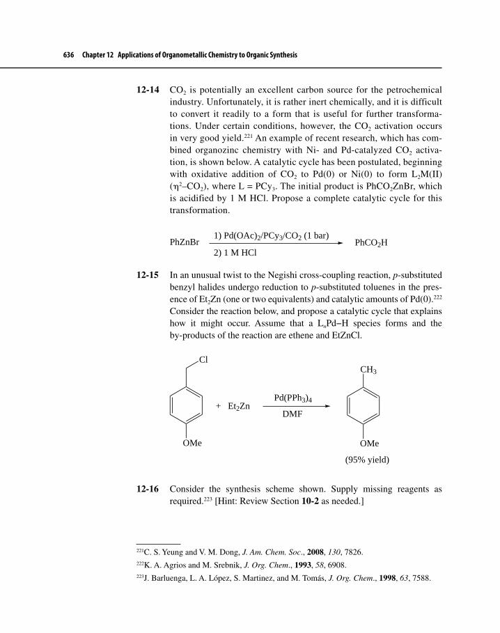
636 Chapter 12 Applications of Organometallic Chemistry to Organic Synthesis
12-14 CO2 is potentially an excellent carbon source for the petrochemical industry. Unfortunately, it is rather inert chemically, and it is difficult to convert it readily to a form that is useful for further transforma-tions. Under certain conditions, however, the CO2 activation occurs in very good yield.221 An example of recent research, which has com-bined organozinc chemistry with Ni- and Pd-catalyzed CO2 activa-tion, is shown below. A catalytic cycle has been postulated, beginning with oxidative addition of CO2 to Pd(0) or Ni(0) to form L2M(II)(η2–CO2), where L = PCy3. The initial product is PhCO2ZnBr, which is acidified by 1 M HCl. Propose a complete catalytic cycle for this transformation.
PhZnBr1) Pd(OAc)2/PCy3/CO2 (1 bar)
2) 1 M HClPhCO2H
12-15 In an unusual twist to the Negishi cross-coupling reaction, p-substituted benzyl halides undergo reduction to p-substituted toluenes in the pres-ence of Et2Zn (one or two equivalents) and catalytic amounts of Pd(0).222
Consider the reaction below, and propose a catalytic cycle that explains how it might occur. Assume that a LnPd−H species forms and the by-products of the reaction are ethene and EtZnCl.
Cl
OMe
+ Et2ZnPd(PPh3)4
DMF
CH3
OMe
(95% yield)
12-16 Consider the synthesis scheme shown. Supply missing reagents as required.223 [Hint: Review Section 10-2 as needed.]
221C. S. Yeung and V. M. Dong, J. Am. Chem. Soc., 2008, 130, 7826.222K. A. Agrios and M. Srebnik, J. Org. Chem., 1993, 58, 6908.223J. Barluenga, L. A. López, S. Martinez, and M. Tomás, J. Org. Chem., 1998, 63, 7588.

Problems 637
(CO)5Cr
OMe
CH3
(CO)5Cr
N
CH3
(CO)5Cr
N
CO2Et
MeO2C
HO N
Ph H
Cr(CO)3MeO2C
HO N
Ph H
12-17 The reaction shown can be considered a combination of a Pd-catalyzed ene reaction and a Suzuki cross-coupling.224 Propose a catalytic cycle for the reaction. One of the key intermediates is structure J.
NTs
Bu
Cl
+
B(OH)2
Pd(PPh3)4
PhMe/KF/60 oCNTs
OO
Ph
Bu
NTs
Pd
Bu
Cl
O
J
12-18 The ene reaction was used to convert acyclic compound K to bicyclic ketone L, as shown on the next page.225 The reaction is catalytic in Pd(0). Propose a catalytic cycle that accounts for the formation of two fused five-membered rings. Assume that one of the intermediates in the cycle is M.
224G. Zhu, X. Tong, J. Cheng, Y. Sun, D. Li, and Z. Zhang, J. Org. Chem., 2005, 70, 1712.225N. H. Ihle and C. H. Heathcock, J. Org. Chem., 1993, 58, 560.

638 Chapter 12 Applications of Organometallic Chemistry to Organic Synthesis
MeO2C
MeO2C
OAc
LnPd/CO
THF
PdLn(OAc)
OMeO2C
MeO2C
MeO2C
MeO2C
O
K LM
12-19 Two different catalysts were required for the transformation shown.226 Propose a mechanism-based explanation for the transformation, clearly stating what the role of each catalyst is.
HO
Ph
+
OAc
[Pd2(dba)3]
[RhCl(COD)2]O
Ph
O
CO
12-20 A Rh-catalyzed Pauson–Khand reaction is shown below. Sometimes an aldehyde (RCHO) is used as a source of CO.227 Assume that the Rh catalyst is of the form LnRh(I), and the by-product of the P–K reaction is R−H.
MeO2C
MeO2C LnRh(I)/RCHO
xylenes/130 oC MeO2C
MeO2C
O
Ph
Ph
+ R−H
a. Propose a catalytic cycle for the carbonylation of the Rh catalyst by RCHO prior to the P–K reaction.
b. It is possible to achieve maximum atom economy if the aldehyde is not only the source of CO, but also is one of the reacting partners in the P–K reaction. What two reactants are necessary to produce cyclopentenone N?
O
PhH
Me
N
226N. Jeong, S. D. Seo, and J. Y. Shin, J. Am. Chem. Soc., 2000, 122, 10220.227T. Shibata, Adv. Synth. Catal., 2006, 348, 2328.

Problems 639
12-21 Show the intermediates and final product that result after the reagents shown are used.228
O
1) Co2(CO)8
2) Grubbs’ first-generation catalyst3) morpholine-N-oxide
The final product was determined to be tricyclic with the following spec-tral information observed:
IR: ν = ca. 1700 (strong) and 1100 cm–1 (medium)1H-NMR: δ 5.97 (singlet, 1H), 4.5 (doublet of doublets, 2H, J = 15–20 Hz), 4.35 ppm (multiplet, 1H); several other peaks13C-NMR: δ 213, 182, 122, 75, 65, 48, 47, 29, 25, 21 ppmElemental analysis: %C = 73.01; %H = 7.25
228M. Rosillo, L. Casabubios, G. Domínguez, and J. Pérez-Castells, Org. Biomol. Chem., 2003, 1, 1450.

13-1 THE ISOLOBAL ANALOGYIn earlier chapters, there have been a variety of examples of similarities between organometallic chemistry and organic chemistry. Such similarities can be envisioned on a broader scale by considering frontier orbitals of the molecular fragments of which organometallic compounds are composed. In his 1981 Nobel lecture, Hoffmann described molecular fragments as isolobal,
if the number, symmetry properties, approximate energy and shape of the frontier orbitals and the number of electrons in them are similar—not identical, but similar.1
To illustrate this definition, we will use of one of Hoffmann’s examples, com-paring fragments of methane with fragments of an octahedrally coordinated transition metal complex ML6. For simplicity, we will consider only σ interac-tions between the metal and the ligands in this complex.2 The fragments to be considered are shown in Figure 13-1.
The parent compounds have filled valence-shell electron configurations, eight electrons (an “octet”) for CH4 and 18 electrons for ML6. Methane is con-sidered to use sp3 hybrid orbitals in bonding, with eight electrons occupying bonding pairs formed from interactions between the hybrids and 1s orbitals on the hydrogens. The metal in ML6, by similar reasoning, uses d2sp3 hybrids to bond to the ligands, with 12 electrons occupying bonding orbitals and six
1R. Hoffmann, Angew. Chem. Int. Ed. Engl., 1982, 21, 711.2Pi interactions can also be considered; see Footnote 1 and H.-J. Krause, Z. Chem., 1988, 28, 129.
Isolobal Groups and Cluster Compounds
THIRTEEN
640

13-1 The Isolobal Analogy 641
nonbonding electrons occupying dxy, dxz, and dyz orbitals. These orbitals are shown in Figure 13-2.
Molecular fragments containing fewer ligands than the parent polyhedra can now be described; for the purpose of the analogy, these fragments are assumed to preserve the original geometry of the remaining ligands.
Tetrahedral CH4 and octahedral ML6 can form 7- and 17-electron fragments having the orbital characteristics shown in Figure 13-3. To form the fragments used in this example, the C–H and M–L bonds are assumed to cleave homolytically.
For example, in the 7-electron fragment CH3, three of the sp3 orbitals of carbon are involved in σ bonding with the hydrogens. The fourth hybrid is sin-gly occupied and at higher energy than the σ bonding pairs of CH3, as shown in Figure 13-3. The frontier orbitals of the 17-electron fragment Mn(CO)5 are similar to those of CH3. The σ interactions between the ligands and Mn in this fragment may be considered to involve five of the metal’s d2sp3 hybrid orbitals. The sixth hybrid is singly occupied and at higher energy than the five σ bonding orbitals; in this respect, it is similar to the singly occupied hybrid in CH3.
Figure 13-1 Octahedral and Tetrahedral Fragments
Parentstructures
ML6 CH4
CH3
CH2
ML5
ML4
–L
–L
–H
–HFragments
Figure 13-2 Orbitals of Parent Structures CH4 and ML6
MCML6CH4
C CH4 4H M ML6 6L
1ssp3
d 2sp3
σ donor...............................dxy dxz dyz

642 Chapter 13 Isolobal Groups and Cluster Compounds
Each of these fragments has a single electron in a hybrid orbital at the vacant site of the parent polyhedron. These orbitals are sufficiently similar to meet Hoffmann’s isolobal definition. Using Hoffmann’s symbol to designate groups as isolobal, we may therefore write the following.
CH3 ML5
7 electrons 17 electrons
Similarly, 6-electron CH2 and 16-electron ML4 are isolobal, as shown in Figure 13-4.
Each of these fragments represents the parent polyhedron, with single elec-trons occupying two hybrid orbitals at otherwise vacant sites; each fragment also has two electrons fewer than the filled shell octet or 18-electron configurations.
CH2 ML4
6 electrons 16 electrons
The absence of a third ligand from the parent polyhedra also gives a pair of iso-lobal fragments, CH and ML3.
CH ML3
5 electrons 15 electrons
These relationships are summarized in Table 13-1.
Figure 13-4 Six- and 16-Electron Fragments
ML4CH2
C CH2 2H M ML4 4L
1ssp3
d 2sp3
σ donor............................dxy dxz dyz
CM
Figure 13-3 Seven- and 17-Electron Fragments
ML5CH3
C CH3 3H M ML5 5L
1ssp3
d 2sp3
σ donor...............................dxy dxz dyz
C M
.........................
...........................

13-1 The Isolobal Analogy 643
Isolobal fragments can be formally combined into molecules, as shown in Figure 13-5. For example, two CH3 fragments, when linked, form ethane, and two Mn(CO)5 fragments form the dimeric (OC)5Mn–Mn(CO)5. Furthermore, organic and organometallic fragments can be intermixed; an example is H3C–Mn(CO)5, also a known compound.
Organic and organometallic parallels are not always this complete. For example, whereas two 6-electron CH2 fragments form ethylene, H2C=CH2, the dimer of the isolobal Fe(CO)4 is not nearly as stable; it is known as a transient
Table 13-1 Isolobal Fragments
Organic InorganicVertices missing from
parent polyhedron Electrons short
of filled shellOrganometallic examplea
Parent: CH4 ML6 0 0 Cr(CO)6
Fragments: CH3 ML5 1 1 Mn(CO)5
CH2 ML4 2 2 Fe(CO)4
CH ML3 3 3 Co(CO)3
aThese examples involve π interactions between the metal and the ligands (affecting the energies of the dxy, dxz, and dyz orbitals); however, the overall electronic structures of the fragments shown are still consistent with their being considered isolobal.
Mn
C
C
CC
CO
O
O
OO
Mn
C
C
CC
CO
O
O
OO
Mn
CC
CC
C
O O
O
OO
+ Mn
C
C
CC
CO
O
O
OO
Mn
CC
CC
C
O O
O
OO
Mn
C
C
CC
CO
O
O
OO
C
H
H
H
+ C
H
H
HC
H
H
HC
H
H
H
C
H
H
H+ C
H
H
HFigure 13-5 Molecules Resulting from the Combination of Isolobal Fragments

644 Chapter 13 Isolobal Groups and Cluster Compounds
species obtained thermally or photochemically from Fe2(CO)9.3 Both CH2 and Fe(CO)4, however, form three-membered rings: cyclopropane and Fe3(CO)12. Although cyclopropane is a trimer of CH2 fragments, Fe3(CO)12 has two bridg-ing carbonyls and is therefore not a perfect trimer of Fe(CO)4. The isoelectronic Ru3(CO)12, on the other hand, is a trimeric combination of three Ru(CO)4 frag-ments (which are isolobal with both Fe(CO)4 and CH2) and can correctly be described as [Ru(CO)4]3. These structures are shown in Figure 13-6.
The 15-electron fragment Ir(CO)3 forms [Ir(CO)3]4, which has an Ir4 core in the shape of a regular tetrahedron. In this complex all the carbonyl groups are terminal. The isoelectronic complexes Co4(CO)12 and Rh4(CO)12 have nearly tetrahedral arrays of metal atoms, but three carbonyls bridge one of the triangu-lar faces in each of these clusters. Compounds are also known having a central tetrahedral core, with one or more Co(CO)3 fragments [isolobal and isoelectronic with Ir(CO)3] replaced by the isolobal CR fragment (shown in Figure 13-7). More simply, individual phosphorus atoms, with five valence electrons, may also be considered isolobal with 15-electron organometallic fragments. Phosphorus atoms readily arrange themselves into tetrahedra; tetrahedral P4 is in fact the most
3M. Poliakoff and J. J. Turner, J. Chem. Soc. A, 1971, 2403.
Figure 13-6 Isolobally Related Three-Membered Rings
CC
C
H
H
H
HH
H
RuRu
RuFe
Fe
Fe
C
CO
O( = terminal CO)
C3H6 Fe3(CO)12 Ru3(CO)12
Figure 13-7 Isolobally Related Tetrahedral Molecules
R
R
Ir Ir
Ir
Ir(CO)3
(CO)3
(CO)3
(CO)3
Co Co
Co
Co(CO)2
(CO)2
(CO)2
(CO)3
( = bridging CO)
Co Co
C
Co(CO)3
(CO)3
(CO)3
R
C Co
C
Co(CO)3
(CO)3
P P
P
PP Co(CO)3
P
P
C C
C
C
H
H H
H

13-1 The Isolobal Analogy 645
common molecular form of this element. Tetrahedral combinations of phospho-rus atoms and isolobal 15-electron organometallic fragments such as Co(CO)3 have also been prepared; one example is shown in Figure 13-7.
13-1-1 Extensions of the AnalogyThe concept of isolobal fragments can be extended beyond the examples given so far, to include charged species, a variety of ligands other than CO, and organome-tallic fragments based on structures other than octahedral. Some of the ways of extending the isolobal parallels can be summarized as follows.
1. The isolobal definition may be extended to isoelectronic fragments having the same coordination number. For example,
Re(CO)5
Because Mn(CO)5 CH3, [Fe(CO)5]+ CH3
[Cr(CO)5]–
2. Gain or loss of electrons from two isolobal fragments yields isolobal fragments. For example,
Because Mn(CO)5 CH3, [Mn(CO)5]+ CH3+
17-electron 7-electron 16-electron 6-electronfragment fragment fragment fragment
[Mn(CO)5]– CH3–
18-electron 8-electronfragment fragment
3. Other two-electron donors are treated similarly to CO.
Mn(CO)5 Mn(NCR)5 [MnCl5]5– CH3
17-electron fragments 7-electron fragment
Co(CO)3 Co(PR3)3 [Co(CN)3]3– CH15-electron fragments 5-electron fragment
4. η5–Cp is considered to occupy three coordination sites and to be a six-electron donor (as C5H5
–).
(η5–C5H5)Fe(CO)2 [Fe(CO)5]+ Mn(CO)5 CH3
17-electron fragments
(η5–C5H5)Re(CO)2 [Re(CO)5]+ Cr(CO)5 CH2
16-electron fragments
Examples of isolobal fragments containing CO and η5–Cp ligands are given in Table 13-2.
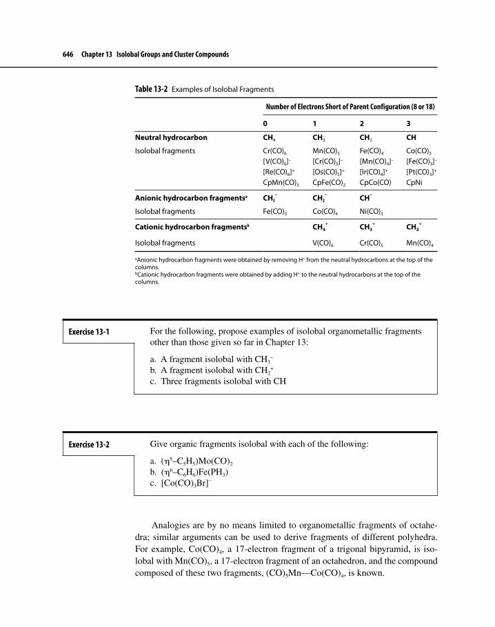
646 Chapter 13 Isolobal Groups and Cluster Compounds
Table 13-2 Examples of Isolobal Fragments
Number of Electrons Short of Parent Configuration (8 or 18)
0 1 2 3
Neutral hydrocarbon CH4 CH3 CH2 CH
Isolobal fragments Cr(CO)6 Mn(CO)5 Fe(CO)4 Co(CO)3
[V(CO)6]– [Cr(CO)5]– [Mn(CO)4]– [Fe(CO)3]–
[Re(CO)6]+ [Os(CO)5]+ [Ir(CO)4]+ [Pt(CO)3]+
CpMn(CO)3 CpFe(CO)2 CpCo(CO) CpNi
Anionic hydrocarbon fragmentsa CH3– CH2
– CH–
Isolobal fragments Fe(CO)5 Co(CO)4 Ni(CO)3
Cationic hydrocarbon fragmentsb CH4+ CH3
+ CH2+
Isolobal fragments V(CO)6 Cr(CO)5 Mn(CO)4
aAnionic hydrocarbon fragments were obtained by removing H+ from the neutral hydrocarbons at the top of the columns.bCationic hydrocarbon fragments were obtained by adding H+ to the neutral hydrocarbons at the top of the columns.
Exercise 13-1 For the following, propose examples of isolobal organometallic fragments other than those given so far in Chapter 13:
a. A fragment isolobal with CH3–
b. A fragment isolobal with CH2+
c. Three fragments isolobal with CH
Exercise 13-2 Give organic fragments isolobal with each of the following:
a. (η5–C5H5)Mo(CO)2
b. (η6–C6H6)Fe(PH3)c. [Co(CO)3Br]–
Analogies are by no means limited to organometallic fragments of octahe-dra; similar arguments can be used to derive fragments of different polyhedra. For example, Co(CO)4, a 17-electron fragment of a trigonal bipyramid, is iso-lobal with Mn(CO)5, a 17-electron fragment of an octahedron, and the compound composed of these two fragments, (CO)5Mn—Co(CO)4, is known.

13-1 The Isolobal Analogy 647
Mn
C
C
CC
CO
O
O
OO
O Co
CC
CC
O
O
O
O
Examples of electron configurations of isolobal fragments of polyhedra having five through seven vertices are given in Table 13-3.4
13-1-2 Examples of Applications of the AnalogyThe isolobal analogy can, in principle, be extended to any molecular fragment having frontier orbitals of suitable size, shape, symmetry, and energy. In many cases, the characteristics of frontier orbitals are not as easy to predict as in the examples cited above, and calculations are necessary to determine the symmetry and energy of molecular fragments. For example, Au(PPh3), a 13-electron frag-ment, has a single electron in a hybrid orbital pointing away from the phosphine.5
This electron is in an orbital that has similar symmetry but somewhat higher energy than the singly occupied hybrid in the Mn(CO)5 fragment.
O Mn
C
C
CC
CO
O
O
OO
P Au
Ph
Ph Ph
4For analysis of the energies and symmetries of fragments of a variety of polyhedra, see R. Hoffmann, Footnote 1; M. Elain and R. Hoffmann, Inorg. Chem., 1975, 14, 1058; and T. A. Albright, R. Hoffmann, J. C. Thibeault, and D. L. Thorn, J. Am. Chem. Soc., 1979, 101, 3801.5D. G. Evans and D. M. P. Mingos, J. Organomet. Chem., 1982, 232, 171.
Table 13-3 Isolobal Relationships for Fragments of Polyhedra
Coordination number of transition metal for parent polyhedron
Organic fragment 5 6a 7Valence electrons of
transition metal fragment
CH3 d9-ML4 d7-ML5 d5-ML6 17CH2 d10-ML3 d8-ML4 d6-ML5 16CH d9-ML3 d7-ML4 15
aExamples have already been considered (Table 13-2).

648 Chapter 13 Isolobal Groups and Cluster Compounds
The Au(PPh3) fragment can be combined with the isolobal Mn(CO)5 and CH3
fragments to form (OC)5Mn—Au(PPh3) and H3C—Au(PPh3).Even a hydrogen atom, with a single electron in its 1s orbital, can in some
cases be viewed as a fragment isolobal with such species as CH3, Mn(CO)5, and Au(PPh3). Hydrides of the first two [i.e., CH4 and HMn(CO)5] are very well known. In addition, in some cases Au(PPh3) and H show surprisingly similar behavior, such as in their ability to bridge triosmium clusters6,7 (Figure 13-8) and the capacity of a gold phosphine fragment to replace hydrogen in fluorescent organic molecules.8
A practical use of isolobal analogies is in suggesting syntheses of new com-pounds. For example, CH2 is isolobal with 16-electron Cu(η5–Cp*) (extension 4 of the analogy, as described previously) and with 14-electron PtL2 (L = PR3, CO);9 all three of these fragments are two ligands and two electrons short of their par-ent polyhedra. Recognition that these fragments are isolobal has been exploited in preparing new organometallic compounds composed of fragments isolobal with fragments of known compounds. Examples of compounds obtained in these studies are shown on the next page.10,11
6A. G. Orpen, A. V. Rivera, E. G. Bryan, D. Pippard, G. Sheldrick, and K. D. Rouse, J. Chem. Soc.,Chem. Commun., 1978, 723. 7B. F. G. Johnson, D. A. Kaner, J. Lewis, and P. R. Raithby, J. Organomet. Chem., 1981, 215, C33. 8T. G. Gray, Comments Inorg. Chem., 2007, 28, 181. 9In a manner similar to the relationship between the “18-electron rule” for octahedra and other structures, and the “16-electron rule” for square planar complexes, isolobal relation-ships between 16-electron fragments of octahedra and 14-electron fragments of square pla-nar structures can also be demonstrated.10G. A. Carriedo, J. A. K. Howard, and F. G. A. Stone, J. Organomet. Chem., 1983, 250, C28.11N. J. Fitzpatrick, P. J. Groarke, and N. M. Tho, Polyhedron, 1992, 11, 2517.
Figure 13-8 Isolobal Au(PPh3) and H
OsOs
Os
C
C
CC
C
C
H
H
C
CC
O
OO
O
O
O
O
O
O
C
OsOs
Os
C
C
CC
C
C
Au
H
C
CC
O
OO
O
O
O
O
O
O
O
C
PPh3
O

13-1 The Isolobal Analogy 649
Previously New compounds known compounds composed of isolobal fragments
Rh
C
Cu
P(C6H5)3
CH H
P(C6H5)3
RhPt
CPPh3
C
O
OO
Rh
CRhCu
CO
O
P Co(CO)3
P
PP Ni
P
P
Another example is provided by recognition of the isolobal nature of the (η5–C5H5)Fe+ and (η4–C4H4)Co+ fragments12 as background for the synthesis of a variety of cyclobutadiene cobalt analogues of ferrocene, including the examples shown below.13
Co Co
12R. Gleiter, H. Schimanke, S. J. Silverio, M. Büchner, and G. Huttner, Organometallics, 1996, 15, 5635.13E. V. Mutseneck, D. A. Loginov, D. S. Perekalin, Z. A. Starikova, D. G. Golovanov, P. V. Petrovskii, P. Zanello, M. Corsini, F. Laschi, and A. R. Kudinov, Organometallics, 2004, 23, 5944.

650 Chapter 13 Isolobal Groups and Cluster Compounds
13-2 CLUSTER COMPOUNDSTransition metal cluster chemistry has developed rapidly during the past several decades. Beginning with simple dimeric molecules such as Co2(CO)8 and Mn2(CO)10,14 chemists have developed syntheses of far more complex clusters, some with interesting and unusual structures and chemical properties. Large clus-ters have been studied with the objective of developing catalysts that may dupli-cate or improve upon the properties of heterogeneous catalysts; the surface of a large cluster may in these cases mimic in some degree the behavior of the surface of a solid catalyst.
Before considering organometallic clusters, we will find it useful to examine the capacity of boron to form clusters. The types of orbital interactions involved in boron-based clusters will provide useful background to understand the types of interactions that occur in organometallic clusters containing transition metals.
13-2-1 BoranesThere are a great many neutral and ionic species composed of boron and hydro-gen, far too numerous to consider in this text.15 For the purposes of illustrating parallels between these species and transition metal organometallic clusters, we will first consider one category of boranes, closo (“cage-like”) boranes, which have the formula BnHn
2–. These boranes are closed polyhedra having n corners; their faces are all triangular (triangulated polyhedra). Each corner is occupied by a BH group; an example, the highly symmetric B6H6
2–, is shown below.
H
BB
B
B
BB
H
H
HH
H
2–
14Some chemists define clusters as having at least three metal atoms.15For a more detailed introductory outline of boron cluster chemistry, see N. N. Greenwood and A. Earnshaw, Chemistry of the Elements, 2nd Ed., Butterworth–Heinemann: Oxford, 1997, pp. 141–181.

13-2 Cluster Compounds 651
Molecular orbital calculations have shown that closo boranes have two types of molecular orbitals that are instrumental in holding the boron framework together:
n orbitals involving interactions between boron orbitals in the outer frame-work (or skeleton) of the structure
1 orbital involving interactions of boron orbitals at the center of the cluster
In total, therefore, there are n + 1 bonding orbitals in the central core.16 These orbitals, occupied by electron pairs, are primarily responsible for holding the core framework of the cluster together.
In addition, there are n boron–hydrogen bonding orbitals involved in the σ bonds between these atoms on the outside of the cluster. Adding these to the n + 1 bonding orbitals in the central core gives a total of 2n + 1 bonding orbitals overall in the cluster.
The B6H62– ion is a useful example; a convenient set of coordinate axes for its
boron atoms is shown in Figure 13-9. Each boron has four valence orbitals (s, px, py, and pz), a total of 24 boron valence orbitals for the cluster. It is convenient to assign the z axis of each boron to point toward the center of the octahedron, with the x and y axes oriented as shown.
The pz and s orbitals of the borons collectively have the same symmetry and may therefore be considered to combine to form sp hybrid orbitals. These hybrid orbitals point in toward the center of the cluster and out toward the hydrogen atoms. The unhybridized 2p orbitals (px and py) of the borons remain to participate in bonding within the B6 core.
16K. Wade, Electron Deficient Compounds, Nelson: London, 1971, pp. 50–59.
Figure 13-9 Coordinate System for Bonding in B6H6
2– (Adapted with permission from G.L. Miessler and D.A. Tarr, Inorganic Chemistry, 3rd ed., Pearson Education: Upper Saddle River, NJ, 2004, p. 573.)
B
B
B
B
B
Bx
x
x
x
x
x
y
y
y
y
y
y
z
z
z
z
z
z

652 Chapter 13 Isolobal Groups and Cluster Compounds
Seven orbital combinations (n + 1) lead to bonding interactions within the B6 core; these are shown in Figure 13-10. Constructive overlap of all six hybrid orbitals at the center of the octahedron yields one framework bonding orbital, labeled A1g.17 Additional bonding interactions are of two types: overlap of two sp hybrid orbitals with parallel p orbitals on four boron atoms (three such inter-actions, symmetry label T1u) and overlap of p orbitals on four boron atoms within the same plane (three interactions, symmetry label T2g). The remaining orbitals form antibonding molecular orbitals or are nonbonding. A summary follows.
17The symmetry label A1g designates the highly symmetric interaction that occurs when all sp hybrids point toward the center of the polyhedron. For an explanation of symmetry labels, see F. A. Cotton, Chemical Applications of Group Theory, 3rd ed., Wiley: New York, 1990, pp. 231–238.
Figure 13-10 Bonding in B6H6
2–
A1g:
T1u:
T2g:

13-2 Cluster Compounds 653
From the 24 valence atomic orbitals of boron the following are formed:
13 bonding orbitals (2n+1), consisting of:7 framework molecular orbitals (n+1):
1 bonding orbital from overlap of sp hybrid orbitals6 bonding orbitals from overlap of p orbitals of boron with sp hybrid
orbitals or with other boron p orbitals 6 boron–hydrogen bonding orbitals (n)11 antibonding or nonbonding orbitals
Similar descriptions of bonding can be derived for other closo boranes. In each case, one particularly useful similarity can be found: there is one more framework bonding pair than the number of vertices in the polyhedron. The extra framework bonding pair is in a highly symmetric orbital resulting from overlap of atomic (or hybrid) orbitals at the center of the polyhedron, similar to the interac-tion labeled A1g in Figure 13-10. In addition, there is a significant gap in energy between the HOMO and the LUMO.18 The numbers of bonding pairs for several closo boranes are shown in Table 13-4.
Together, the closo structures make up only a small fraction of all known borane species. Additional structural types can be obtained by removing one or more corners from the closo framework. Removal of one corner yields a nido (“nest-like”) structure, removal of two corners an arachno (“spiderweb-like”) structure, and removal of three corners a hypho (“net-like”) structure.19 Examples
18K. Wade, “Some Bonding Considerations” in B.F.G. Johnson, Ed., Transition Metal Clusters, Wiley: New York, 1980, p. 217.19Detailed rules for classifying boranes and related compounds are provided in G. J. Leigh, Ed., Nomenclature of Inorganic Chemistry, Blackwell Scientific: Oxford, England, 1990, pp. 207–237.
Table 13-4 Bonding Pairs for Closo Boranes
Framework bonding pairs
FormulaTotal valence electron pairs
A Symmetrya
(overlap at center)Other
frameworkB–H bonding
pairs
B6H62– 13 1 6 6
B7H72– 15 1 7 7
B8H82– 17 1 8 8
BnHn2– 2n + 1 1 n n
aThese are bonding pairs occupying the highly symmetric orbital that results from the combination of all sp hybrid orbitals pointing directly toward the center of the polyhedron. The actual designation (such as A1g) depends on the overall symmetry of the cluster.

654 Chapter 13 Isolobal Groups and Cluster Compounds
of three related closo, nido, and arachno borane structures are shown in Figure 13-11, and the structures of the boron core of selected additional boranes are shown in Figure 13-12.
The classification of structural types can often be done more conveniently on the basis of valence electron counts. Various schemes for relating electron counts to structures have been proposed, with most proposals based on the set of rules formulated by Wade in 1971.20 A classification scheme based on these rules is summarized in Table 13-5.
20K. Wade, Adv. Inorg. Chem. Radiochem., 1976, 18, 1.
Figure 13-11Closo, Nido, and Arachno Borane Structures
B
B
BB
B
B
BH
H
H
H
H
H
H
B
B
BB
BB
HH
H
H
H
H
B
B
B
BB
H
H
H2
H2
H2
closo nido arachnoB7H7
2– B6H10 B5H11
( = bridging H)
Figure 13-12 Structures of Closo, Nido, and Arachno Boranes
6:
9:
12:
closo nido arachno

13-2 Cluster Compounds 655
In addition, it is sometimes useful to relate the total valence electron count in boranes (and, as we shall see, organometallic clusters) to the structural type. In closo boranes, the total number of valence electron pairs is equal to the sum of the number of vertices in the polyhedron (at each boron, one electron pair is involved in boron–hydrogen bonding) and the number of framework bond pairs. For example, in B6H6
2– there are 26 valence electrons, or 13 pairs (=2n + 1, as mentioned previously). The number of vertices in the parent polyhedron (an octa-hedron) is six, and the number of framework bond pairs is seven (n + 1; see Figure 13-10). The total of 13 pairs corresponds to the 6 pairs involved in bonding to the hydrogens (one per boron) and the 7 pairs involved in framework bonding. These electron counts are summarized for two sets of examples, based on six and 12 vertices in parent polyhedra, in Table 13-6.
13-2-2 Method for Classifying StructuresFrom a practical standpoint, it is useful to have a classification scheme based on molecular formulas rather than parent polyhedra (which may not immediately be obvious). In addition, such a classification scheme should ideally be adaptable to other clusters, whether or not they involve the element boron. Here is one such scheme.
Table 13-5 Classification of Cluster Structures
Label Corners occupied Pairs of framework bonding electrons Empty corners
closo n corners of n-cornered polyhedron n + 1 0nido (n – 1) corners of n-cornered polyhedron n + 1 1arachno (n – 2) corners of n-cornered polyhedron n + 1 2hypho (n – 3) corners of n-cornered polyhedron n + 1 3
Table 13-6 Examples of Electron Counting in Boranes
Vertices in parent polyhedron Classification
Boron atoms in cluster
Valence electrons
Framework electron pairs Examples
Formally derived from
6 closo 6 26 7 B6H62– B6H6
2–
6 nido 5 24 7 B5H9 B5H54–
6 arachno 4 22 7 B4H10 B4H46–
12 closo 12 50 13 B12H122– B12H12
2–
12 nido 11 48 13 B11H132– B11H11
4–
12 arachno 10 46 13 B10H15– B10H10
6–

656 Chapter 13 Isolobal Groups and Cluster Compounds
Classi� cation Formally derived from21
closo BnHn2–
nido BnHn4–
arachno BnHn6–
hypho BnHn8–
For boranes, the matching formulas above can be obtained by subtracting a sufficient number of H+ ions (such that the number of boron atoms becomes equal to the number of hydrogen atoms) from the actual formulas (except for the closo clusters, the number of hydrogen atoms in general is greater than the number of boron atoms). For example, to classify B5H11, subtract six H+ ions from the formula
B5H11 – 6 H+ B5H56–
The resulting formula matches the arachno classification.
13-2-3 HeteroboranesThe electron counting schemes described for boranes can be extended to isoelec-tronic species such as carboranes,22 clusters containing both carbon and boron as framework atoms. The CH+ unit is isoelectronic with BH; many compounds are known in which one or more BH groups have been formally replaced by CH+ (or by C, which has the same number of electrons as BH). For example, the replace-ment of two BH groups in closo-B6H6
2– with CH+ yields closo-C2B4H6.
B6H62– – 2 BH = B4H4
2–
B4H42– + 2 CH+ = C2B4H6
21This is a formalism only and does not, except for the closo classification, imply that ions of the given formula (such as BnHn
8–) actually exist.22Also known as carbaboranes.
Example 13-1 The following examples illustrate this method for classifying boranes according to structural type:
a. B10H14 B10H14 – 4 H+ = B10H104– Classification: nido
b. B2H7– B2H7
– – 5 H+ = B2H26– Classification: arachno
c. B8H16 B8H16 – 8 H+ = B8H88– Classification: hypho
Exercise 13-3 Classify the following boranes by structural type.
a. B5H8– b. B11H11
2– c. B10H18

13-2 Cluster Compounds 657
Closo, nido, and arachno carboranes are all known, most commonly containing two carbon atoms; examples are shown in Figure 13-13. Examples of chemical formulas corresponding to these designations are as follows.
Type Borane Example Carborane Example
closo BnHn2– B12H12
2– C2Bn–2Hn C2B10H12
nido BnHn+423 B10H14 C2Bn–2Hn+2 C2B8H12
arachno BnHn+624 B9H15 C2Bn–2Hn+4 C2B7H13
Carboranes may be classified structurally using the same method as for boranes. Because a carbon atom has the same number of valence electrons as a boron atom plus a hydrogen atom, each C can be converted to BH in the classifi-cation scheme. For example, for a carborane having the formula C2B7H13,
C2B7H13 (BH)2B7H13 = B9H15
B9H15 – 6 H+ B9H96–
The classification of C2B7H13 is therefore arachno.Many derivatives of boranes containing other main group atoms (heteroa-
toms) are also known. These “heteroboranes” may be classified by formally converting the heteroatom to a BHx group having the same number of valence electrons and then proceeding as in previous examples. For some of the most common heteroatoms, the following substitutions can be used.
Heteroatom Replace with
C, Si, Ge, Sn BH N, P, As BH2
S, Se BH3
23Nido boranes may also have the formulas BnHn+3– and BnHn+2
2–.24Arachno boranes may also have the formulas BnHn+5
– and BnHn+42–.
Figure 13-13 Examples of Heteroboranes
C
H
B B
C
B
C
H
H
H
H
H
C2B3H5
closo
C
BB
B
B
H H
H
H
H
H
H
C2B4H8
nido
BB
B
B
B
B
BB
B
N
B
H H
NB10H13
(each B and N also has one terminal H atom)
nido
B
B
B
B
CH2C
B
B
B
C2B7H13arachno
H2
HH
(each B also has one terminal H atom)

658 Chapter 13 Isolobal Groups and Cluster Compounds
For example, to classify the heteroborane having the formula B10H12Se,
B10H12Se B10H12(BH3) = B11H15
B11H15 – 4 H+ B11H114–
The classification of B10H12Se is therefore nido.
Although it may not be surprising that the same set of electron counting rules can be used to satisfactorily describe such similar compounds as boranes and carboranes, it is of interest to examine how far the comparison can be extended. Can Wade’s rules, for example, be used effectively on compounds containing organometallic fragments in place of boron, carbon, or other atoms? Can the rules be extended even further, to describe the bonding in polyhedral organometallic clusters?
13-2-4 Metallaboranes and MetallacarboranesThe CH group of a carborane is isolobal with 15-electron fragments of an octahedron such as Co(CO)3 and Ni(η5–Cp). Similarly, BH, which has four valence electrons, is isolobal with 14-electron fragments such as Fe(CO)3 and Co(η5–Cp). These organometallic fragments have been found in substituted boranes and carboranes in which the organometallic fragments substitute for the isolobal CH and BH groups. For example, the organometallic derivatives of B5H9 shown in Figure 13-14 have been synthesized.
Theoretical calculations on the iron derivatives have supported the view that Fe(CO)3 bonds in a manner isolobal with BH.25 In both fragments, the orbitals involved in framework bonding within the cluster are similar (Figure 13-15). In BH, the orbitals participating in framework bonding are an spz hybrid pointing toward the center of the polyhedron and px and py orbitals tangential to the surface of the cluster. In Fe(CO)3, an spzdz2 hybrid points toward the center, and pd hybrid orbitals are oriented tangentially to the cluster surface.
25R. L. DeKock and T. P Fehlner, Polyhedron, 1982, 1, 521.
Exercise 13-4 Determine formulas of boranes isoelectronic with the following.
a. closo-C2B3H5
b. nido-CB5H9
c. SB9H9 (classify as closo, nido, or arachno)d. CPB10H11 (classify as closo, nido, or arachno)

13-2 Cluster Compounds 659
Figure 13-15 Orbitals of Isolobal Fragments BH and Fe(CO)3
BH Fez
x
y
x
z
ypy
pxpd hybrid
spz hybrid spzdz2 hybrid
Figure 13-14 Organometallic Derivatives of B5H9
HB B
B
B B
FeC C
C
Co
OO
O
HH H
HB B
B BH
H HH
B B
B BH
H H
(each B also has one terminal H atom)
Examples of metallaboranes and metallacarboranes are numerous.26 Selected examples with closo structures are given in Table 13-7.
Anionic boranes and carboranes can also act as ligands toward metals in a manner resembling that of cyclic organic ligands. For example, nido carboranes of formula C2B9H11
2– have p orbital lobes pointing toward the “missing” site of the icosahedron (remember that the nido structure corresponds to a closo struc-ture [which in this case is the 12-vertex icosahedron] with one vertex missing). This arrangement of p orbitals can be compared with the p orbitals of the cyclo-pentadienyl ring, as shown in Figure 13-16.
The similarity between these ligands is sufficient that C2B9H112– can bond
to iron to form a carborane analogue of ferrocene, [Fe(η5–C2B9H11)2]2–. A mixed ligand sandwich compound containing one carborane and one cyclopentadienyl ligand, [Fe(η5–C2B9H11)(η5–C5H5)], has also been made (Figure 13-17),27 and the chemistry of sandwich compounds involving carboranes as ligands is now exten-sive.28 Numerous other examples of boranes and carboranes serving as ligands to transition metals are also known.29
26A useful brief review of boranes as ligands is in N. N. Greenwood, Coord. Chem. Rev., 2002, 226, 61.27M. W. Hawthorne, D. C. Young, and P. A. Wegner, J. Am. Chem. Soc., 1965, 87, 1818.28M. Corsini, F. Fabrizi de Biani, and P. Zanello, Coord. Chem. Rev., 2006, 250, 1351.29K. P. Callahan and M. F. Hawthorne, Adv. Organomet. Chem., 1976, 14, 145.

660 Chapter 13 Isolobal Groups and Cluster Compounds
Figure 13-16 Comparison of C2B9H11
2– with C5H5–.
Each B and C atom also has a terminal H atom, not shown.
CC
= boron
2–
nido-C2B9H112– C5H5
–
–
Table 13-7 Metallaboranes and Metallacarboranes with Closo Structures
Number of framework atoms Shape Examples
6 Octahedron B4H6(CoCp)2
C2B3H5Fe(CO)3
7 Pentagonal C2B4H6Ni(PPh3)2
bipyramidC2B3H5(CoCp)2
8 Dodecahedron C2B4H4[(CH3)2Sn]CoCp
12 Icosahedron C2B7H9(CoCp)3
C2B9H11Ru(CO)3
Metallaboranes and metallacarboranes can be classified structurally by a procedure similar to that for boranes and their main group derivatives.30 In this scheme, the valence electron count of the metal-containing fragment is first deter-mined and then compared with the requirements of the 18-electron rule. This fragment can then be considered equivalent to a BHx fragment needing the same number of electrons to satisfy the octet rule. For example, a 15-electron fragment
30D. M. P. Mingos, Acc. Chem. Res., 1984, 17, 311.

13-2 Cluster Compounds 661
such as Co(CO)3 is three electrons short of 18; this fragment may be considered the equivalent of the five-electron fragment BH2, which is three electrons short of an octet. Examples of organometallic fragments and their corresponding BHx fragments are given in Table 13-8.
Figure 13-17 Carborane Analogues of Ferrocene
CC
= boron
Fe
CC
Fe
CC
2–
Table 13-8 Organometallic and Borane Fragments
Valence electrons in organometallic fragment Example
Valence electrons in borane fragment Borane fragment
13 Mn(CO)3 3 B
14 Co(η5-Cp) 4 BH15 Co(CO)3 5 BH2
16 Fe(CO)4 6 BH3
The following examples illustrate that the method described previously for classifying boranes can also be used for metallaboranes.
B4H8(CoCp)B4H8(CoCp) B4H8(BH) = B5H9
B5H9 – 4 H+ = B6H64– Classification: nido
[C2B9H11Re(CO)3]–
[C2B9H11Re(CO)3]– [(BH)2B9H11(B)]– = B12H13–
B12H13– – H+ = B12H12
2– Classification: closo
Example 13-2

662 Chapter 13 Isolobal Groups and Cluster Compounds
13-2-5 Carbonyl ClustersMany carbonyl clusters have structures similar to boranes; it is therefore of inter-est to determine to what extent the approach used to describe bonding in boranes may also be applicable to bonding in carbonyl clusters.
According to Wade, in addition to the obvious relation shown in equation 13.1 below, the valence electrons in a cluster can be assigned to framework and metal–ligand bonding, as shown in equation 13.2.31
Total number of Number of valence Number of valence valence electrons = electrons contributed + electrons contributedin cluster by metal atoms by ligands 13.1
Total number of Number of electrons Number of electronsvalence electrons = involved in framework + involved in metal–in cluster interactions ligand interactions 13.2
As we have seen previously, the number of electrons involved in framework inter-actions in boranes is related to the classification of the structure as closo, nido, etc. Rearranging equation 13.2 gives the following.
Number of electrons Total number of Number of electronsinvolved in framework = valence electrons – involved in metal–interactions in cluster ligand interactions 13.3
For a borane, two electrons are assigned to each boron–hydrogen bond (including each 3-center, 2-electron bond for bridging hydrogens). For a tran-sition metal–carbonyl complex, Wade suggests that 12 electrons per metal are either involved in metal–carbonyl bonding (to all carbonyls on a metal) or are nonbonding and therefore unavailable for participation in framework bonding. The result is that there is a net difference of 10 electrons per framework atom in comparing boranes with transition metal carbonyl clusters. A metal–carbonyl analogue of closo-B6H6
2–, which has 26 valence electrons, would therefore need a total of 86 valence electrons to adopt a closo structure. An 86-electron cluster that satisfies this requirement is Co6(CO)16. Like B6H6
2–, Co6(CO)16 has an octa-hedral framework. As in the case of boranes, nido structures correspond to closo
31K. Wade, Adv. Inorg. Chem. Radiochem., 1976, 18, 1.
Exercise 13-5 Classify the following by structural type.a. B3H7[Fe(CO)4]2 b. C2B9H11(CoCp)2

13-2 Cluster Compounds 663
Table 13-9 Electron Counting in Main Group and Transition Metal Clusters
Structure type Main group cluster Transition metal cluster
closo 4n + 2 14n + 2nido 4n + 4 14n + 4arachno 4n + 6 14n + 6hypho 4n + 8 14n + 8
geometries from which one vertex is empty; arachno structures lack two vertices, and so on. The valence electron counts corresponding to the various structural classifications for main group and transition metal clusters are summarized in Table 13-9.
Examples of closo, nido, and arachno borane and transition metal clus-ters are given in Table 13-10. In each case, the transition metal cluster has an electron count exceeding the matching borane cluster by 10 valence electrons per framework atom. For example, for four framework atoms per cluster, the transition metal clusters exceed the matching borane clusters by 40 valence electrons.
Transition metal clusters formally containing seven metal–metal framework bonding pairs are among the most common; examples illustrating the structural diversity of these clusters are given in Table 13-1132 and Figure 13-18.
Predicted structures of transition metal–carbonyl complexes using Wade’s rules are often, but not always, accurate.33 For example, the clusters M4(CO)12 (M = Co, Rh, Ir) have 60 valence electrons and are predicted to be nido complexes (14n + 4 valence electrons). A nido structure would be a trigo-nal bipyramid (the parent structure) with one position vacant. X-ray crystal-lographic studies, however, have shown these complexes to have tetrahedral metal cores.34
13-2-6 Carbon-Centered ClustersIn recent years, many compounds have been synthesized, often fortuitously, inwhich one or more atoms have been partially or completely encapsulated within
32K. Wade, “Some Bonding Considerations,” In B.F.G. Johnson, Ed., Transition Metal Clusters, Wiley: New York, 1980, p. 232.33Limitations of Wade’s rules are discussed in R. N. Grimes, “Metallacarboranes and Metallaboranes,” In G. Wilkinson, F. G. A. Stone, and W. Abel, Eds., Comprehensive Organometallic Chemistry, Vol. 1, Pergamon Press: Elmsford, NY, 1982, p. 473.34The metal cores of Co4(CO)12 and Rh4(CO)12 are slightly distorted; as mentioned earlier in Chapter 13 (see Figure 13-4), these complexes have three bridging carbonyls on one triangular face.
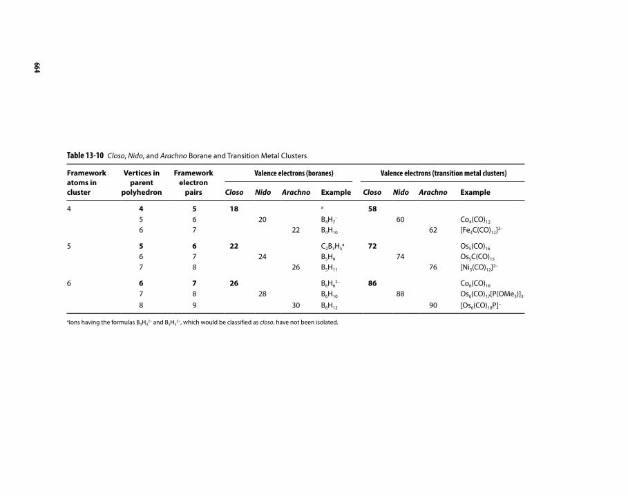
664
Table 13-10 Closo, Nido, and Arachno Borane and Transition Metal Clusters
Framework atoms in cluster
Vertices in parent
polyhedron
Framework electron
pairs
Valence electrons (boranes) Valence electrons (transition metal clusters)
Closo Nido Arachno Example Closo Nido Arachno Example
4 4 5 18 a 585 6 20 B4H7
– 60 Co4(CO)12
6 7 22 B4H10 62 [Fe4C(CO)12]2–
5 5 6 22 C2B3H5a 72 Os5(CO)16
6 7 24 B5H9 74 Os5C(CO)15
7 8 26 B5H11 76 [Ni5(CO)12]2–
6 6 7 26 B6H62– 86 Co6(CO)16
7 8 28 B6H10 88 Os6(CO)17[P(OMe3)]3
8 9 30 B6H12 90 [Os6(CO)18P]–
aIons having the formulas B4H42– and B5H5
2–, which would be classified as closo, have not been isolated.

13-2 Cluster Compounds 665
Table 13-11 Clusters That Formally Contain Seven Metal–Metal Framework Bond Pairs
Number of framework atoms
Cluster type Shape Examples
7 Capped closoa
Capped octahedron
[Rh7(CO)16]3–
6 closo Octahedron Rh6(CO)16
6 Capped nidob
Capped square pyramid
H2Os6(CO)18
5 nido Square pyramid
Ru5C(CO)15
4 arachno Butterfly [HFe4(CO)13]– c
aA capped closo cluster has a valence electron count equivalent to neutral BnHn.bA capped nido cluster has the same electron count as a closo cluster, equivalent to BnHn
2–.cThis complex has an electron count matching a nido cluster, but it adopts the butterfly structure expected for arachno. This is one of many examples in which structures of metal complexes are not predicted accurately by Wade’s rules.
Rh Rh
Rh
Rh Rh
Rh
Rh Rh
Rh
Rh Rh
Rh Rh
Ru Ru
Os Os
Os Os
Os Os
CRu Ru
Ru
Fe
Fe
Fe
Fe
metal clusters. The most common of these cases have been carbon-centered clusters (sometimes called carbide clusters), with carbon exhibiting coordination numbers and geometries not found in classical organic structures. Other nonmetals

666 Chapter 13 Isolobal Groups and Cluster Compounds
such as nitrogen have also been found encapsulated in clusters. Examples of these unusual coordination geometries are shown in Figure 13-18.
Encapsulated atoms contribute their valence electrons to the total electron count. For example, carbon contributes its four valence electrons in Ru6C(CO)17 to give a total of 86 electrons, corresponding to a closo electron count.
How is it possible for carbon or other atoms having only four valence orbitals to form bonds to more than four surrounding transition metal atoms? Ru6C(CO)17 is again a useful example. The octahedral Ru6 core has framework
molecular orbitals (Figure 13-19) similar to those of B6H62– (Figure 13-10). The
key point is that carbon is not restricted to forming bonds with individual atoms (as is commonly described in organic compounds of carbon), but can partici-pate in the formation of molecular orbitals extending through carbon from the surrounding metals. Figure 13-19 shows the orbitals from which four of the most important bonding orbitals in the central Ru6C core are derived. The 2s orbital of carbon can interact with six metal orbitals (hybrid orbitals, involving significant d character) in a σ fashion, as shown in the top diagram in Figure 13-19 (labeled A1g). In addition, each of the carbon’s 2p orbitals can participate in more complex interactions, as shown in the three lower diagrams in Figure 13-19 (labeled T2u). The net result of these interactions is the formation of four C–Ru bonding orbitals, occupied by electron pairs to hold the carbon in the center of the “cage.”
Figure 13-18 Carbon- and Nitrogen-Centered Clusters (Adapted with permission from G.L. Miessler and D.A. Tarr, Inorganic Chemistry, 3rd ed., Pearson Education: Upper Saddle River, NJ, 2004, p. 587.)
Fe
Fe
Fe
Fe
Ru Ru
Ru
Ru Ru
Ru
Ru RuN
Ru Ru
Ru
CoCo
Co
Co
Co
C C CCo Co
Co
Fe4C(CO)13 Ru6C(CO)17 [Co8C(CO)18]2– [Ru5N(CO14)]–
Exercise 13-6 Verify the electron counts and cluster type of the clusters listed in Table 13-11.

Problems 667
Figure 13-19 Bonding Interactions between Central Carbon and Octahedral Ru6
A1g:
T2u:
pz py
px
s
Suggested Readings
The Isolobal AnalogyR. Hoffmann, Angew. Chem. Int. Ed. Engl., 1982, 21, 711–724 (Nobel lecture).
BoranesK. Wade, Electron Deficient Compounds, Nelson: New York, 1971.N. N. Greenwood and A. Earnshaw, Chemistry of the Elements, 2nd ed., Butterworth–
Heinemann: Oxford, 1997, pp. 141–181.As ligands: N. N. Greenwood, Coord. Chem. Rev., 2002, 226, 61–69.
MetallacarboranesR. N. Grimes, in E. W. Abel, F. G. A. Stone, and G. Wilkinson, eds., Comprehensive
Organometallic Chemistry II, Pergamon Press: Oxford, 1995, Vol. 1, Chap. 9, pp. 373–430.
Analogues of metallocenesM. Corsini, F. Fabrizi de Biani, P. Zanello, Coord. Chem. Rev., 2006, 250, 1351.
Problems13-1 Propose organic fragments isolobal with the following:
a. [Re(CO)4]b. Tc(CO)4(PPh3)
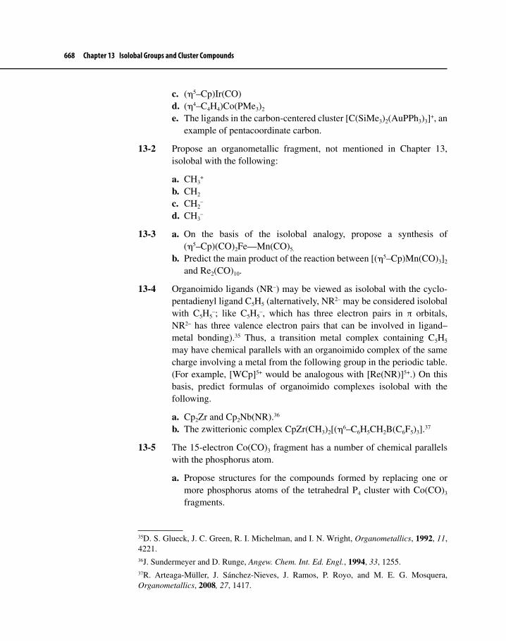
668 Chapter 13 Isolobal Groups and Cluster Compounds
c. (η5–Cp)Ir(CO)d. (η4–C4H4)Co(PMe3)2
e. The ligands in the carbon-centered cluster [C(SiMe3)2(AuPPh3)3]+, anexample of pentacoordinate carbon.
13-2 Propose an organometallic fragment, not mentioned in Chapter 13, isolobal with the following:
a. CH3+
b. CH2
c. CH2–
d. CH3–
13-3 a. On the basis of the isolobal analogy, propose a synthesis of(η5–Cp)(CO)2Fe—Mn(CO)5.
b. Predict the main product of the reaction between [(η5–Cp)Mn(CO)3]2
and Re2(CO)10.
13-4 Organoimido ligands (NR–) may be viewed as isolobal with the cyclo-pentadienyl ligand C5H5 (alternatively, NR2– may be considered isolobal with C5H5
–; like C5H5–, which has three electron pairs in π orbitals,
NR2– has three valence electron pairs that can be involved in ligand–metal bonding).35 Thus, a transition metal complex containing C5H5
may have chemical parallels with an organoimido complex of the same charge involving a metal from the following group in the periodic table. (For example, [WCp]5+ would be analogous with [Re(NR)]5+.) On this basis, predict formulas of organoimido complexes isolobal with the following.
a. Cp2Zr and Cp2Nb(NR).36
b. The zwitterionic complex CpZr(CH3)2[(η6–C6H5CH2B(C6F5)3].37
13-5 The 15-electron Co(CO)3 fragment has a number of chemical parallels with the phosphorus atom.
a. Propose structures for the compounds formed by replacing one ormore phosphorus atoms of the tetrahedral P4 cluster with Co(CO)3
fragments.
35D. S. Glueck, J. C. Green, R. I. Michelman, and I. N. Wright, Organometallics, 1992, 11, 4221.36J. Sundermeyer and D. Runge, Angew. Chem. Int. Ed. Engl., 1994, 33, 1255.37R. Arteaga-Müller, J. Sánchez-Nieves, J. Ramos, P. Royo, and M. E. G. Mosquera, Organometallics, 2008, 27, 1417.

Problems 669
b. Like Co(CO)3, the (η5–Cp)Mo(CO)2 fragment may substitute forphosphorus atoms in P4. Propose formulas and structures for the clusters that would result from such substitution.38
13-6 Classify as closo, nido, or arachno.
a. B10H142–
b. C3B5H7
c. PCB10H11
d. B4H6(RhCp)2
e. B3H8Re(CO)3
f. C2B9H11Os(CO)3
13-7 Classify as closo, nido, or arachno.
a. B8H12
b. C2B7H12–
c. AsCB9H11–
d. B4H6(CoCp)2
e. C2B7H9(CoCp)3
f. C2B4H6Ni(PPh3)2
13-8 Azaboranes are derivatives of boranes in which nitrogen atoms occupyone or more structural positions. Classify the following azaboranes as closo, nido, or arachno.39
a. B3H2(CMe3)3(NCMe3)b. B3H2(CMe3)2(NEt2)(NCMe3)
13-9 Determine the electron counts for the clusters in Figure 13-18 (except forRu6C(CO)17), and classify as closo, nido, or arachno.
13-10 The fragment Co(η4–C4H4) is isolobal with Fe(η5–C5H5).
a. What compound would result by replacing part of ferrocene by thiscobalt fragment?
b. A solution of sodium cyclopentadienide in THF was added to a stirredsolution of (η4–C4Me4)Co(CO)2I, also in THF. After reaction, the solvent was removed under vacuum, and the residue was extractedinto petroleum ether. Removal of solvent and purification by subli-mation yielded a yellow–orange solid. This product showed two 1HNMR resonances, at chemical shifts of 1.55 and 4.53 ppm; it had no
38T. Kilthau, B. Nuber, and M. L. Ziegler, Chem. Ber., 1995, 128, 197.39M. Müller, T. Wagner, U. Englert, and P. Paetzold, Chem. Ber., 1995, 128, 1.

670 Chapter 13 Isolobal Groups and Cluster Compounds
infrared bands between 1800 and 2100 cm–1. Suggest a structure of this product.
c. In a separate reaction, a solution containing the ion C4Me4P– was added to a stirred solution of (η4–C4Me4)Co(CO)2I, with THF again used as the solvent. Isolation by a similar procedure as in b gave a product with a single 31P NMR resonance and no infrared bands between 1800 and 2100 cm–1. Elemental analysis gave 62.91% C and 8.05% H by mass. Propose a structure of this product.40
P
MeMe
MeMe
–
C4Me4P–
13-11 The ligand In[C(SiMe3)3] is known to occupy positions similar to terminal carbonyl ligands; for example, like Ni(CO)4, the complex Ni[In{C(SiMe3)3}4] is tetrahedral.41 Are CO and In[C(SiMe3)3] isolobal? [Suggestion: Consider the potential donor and acceptor orbitals of the ligands.]
13-12 Ligands having the formula GaR (R = alkyl) exhibit similarities to the carbonyl ligand. Show how a GaR ligand could act as both a σ donor and a π acceptor. What would be the formula of an 18-electron Zr complex containing only η5–Cp and GaR ligands?42
13-13 Identify the first-row transition metal in the following closo complexes:43
a. [CB7H8M(CO)3]–b. C2B9H11M(CO)2
13-14 Cp2Zr(CH3)2 reacts with the highly electrophilic borane HB(C6F5)2 to form a product having stoichiometry (CH2)[HB(C6F5)2]2(ZrCp2); the product is an example of pentacoordinate carbon.44
40E. V. Mutseneck, D. A. Loginov, D. S. Perekalin, Z. A. Starikova, D. G. Golovanov, P. V. Petrovskii, P. Zanello, M. Corsini, F. Laschi, and A. R. Kudinov, Organometallics, 2004, 23, 5944.41W. Uhl, M. Pohlmann, and R. Wartchow, Angew. Chem. Int. Ed., 1998, 37, 961.42X. Yang, B. Quillian, Y. Wang, P. Wei, and G. H. Robinson, Organometallics, 2004, 23, 5119.43A. Franken, T. D. McGrath, and F. G. A. Stone, Organometallics, 2005, 24, 5157; B. E. Hodson, T. D. McGrath, and F. G. A. Stone, Inorg. Chem., 2004, 43, 3090.44R. E. von H. Spence, D. J. Parks, W. E. Piers, M-A. MacDonald, M. J. Zaworotko, and S. J. Rettig, Angew. Chem. Int. Ed. Engl., 1995, 34, 1230.

Problems 671
a. Propose a structure for this product. [Useful information: The 1H NMR spectrum has singlets at δ = 5.23 (relative area = 5) and 2.29 ppm (rel. area = 1) and a broad signal at δ = –2.05 ppm (rel. area = 1); the 19F NMR spectrum has three resonances; and the 11B NMR has a single peak.]
b. An isomer of this product, [Cp2ZrH]+[CH2{B(CF5)2}2(μ–H)]–, has been proposed as a potential Z–N catalyst. Suggest a mechanistic pathway by which this isomer might serve as a catalyst for the polym-erization of ethylene.45
13-15 Refluxing Ru3(CO)12 with the tetramethyldisilylene compound shown below in xylene solvent gives several products. The most interesting of these has the following characteristics:
IR (cm–1): 1934–1985 (4 peaks), 1807, 1779 1H NMR: multiple peaks between 6.82 and 4.41 ppm; no peaks
in the range 0–1 ppm Composition by mass: 25.67% C, 0.914% H, 14.51% O Additional information: each oxygen is attached to carbon; one
carbon is significantly different from all the rest. Finally, some would say that this molecule wears three caps!
Propose a structure for this product.46
Si SiMe2 Me2
45See also L. Jia, X. Yang, C. Stern, and T. J. Marks, Organometallics, 1994, 13, 3755.46D. Chen, B. Mu, S. Xu, and B. Wang, J. Organomet. Chem., 2006, 691, 3823.

TWO
A-1
List of Abbreviations
□ Empty coordination site
Isolobal symbol
A bond line that indicates stereochemistry is not specified
Io, IIo, IIIo Primary, secondary, tertiary
α Position on carbon chain attached to metal; α denotes carbondirectly attached to metal
β Position on carbon chain attached to metal; β denotes one carbon beyond the α position
βn Natural bite angle; a measure of the P−M−P bond angle ofdiphosphine and diphosphite ligands
ηn Descriptor of hapticity (the number of binding sites on a ligand);the superscript designates the number of binding sites
θ Cone angle; a measure of the steric bulk of phosphine ligands
μ Descriptor for bridging ligand(s)
ν Frequency
χ A measure of the electronic properties of PR3 ligands; each Rgroup has a different χ value. The lower the value of χ, the moreelectron donating the R group and thus the phosphine.
A Associative substitution
ADMET Acyclic diene metathesis
Ar Aryl
Bn Benzyl (PhCH2-)
Boc or t-Boc tert-butoxycarbonyl; a protecting group, typically used to protect amines
Bu Butyl (previously known as n-butyl)
APPENDIX A

A-2 Appendix A List of Abbreviations
t-Bu tert-Butyl or tert-Bu
CO Carbonyl ligand
COD (or cod) 1,5-Cyclooctadiene
COT (or cot) 1,3,5,7-Cyclooctatetraene
Cp Cyclopentadienide ion, C5H5–
Cp* Pentamethylcyclopentadienide ion, C5(Me)5–
Cp′ Ethyltetramethylcyclopentadienide ion, C5(Et)(Me)4–
Cy Cyclohexyl
D Dissociative substitution
dba Dibenzylideneacetone (Ph−CH=CH−C(=O)−CH=CH−Ph); a useful ligand for Pd-catalyzed reactions in organic synthesis
DMA N,N-Dimethylacetamide
DMAP 4-Dimethylaminopyridine; used as a basic catalyst
DMF N,N-Dimethylformamide
DMSO Dimethylsulfoxide
dppf [1,1′-bis(Diphenylphosphino)ferrocene, Fe(C5H4PPh2)2]; a useful bidentate ligand
dn Formal d-electron configuration
E or E+ Electrophile
E-factor The environmental factor (the ratio of the total mass of waste to the mass of the desired product); a measure of how green a reaction or process is
ee or % ee Percent enantiomeric excess
Et Ethyl
Et2O Diethyl ether
EtOH Ethanol
eu Entropy units (cal/mol K)
en Ethylenediamine
fac Facial stereochemistry (three ligands occupy the same face of an octahedral complex)
Fp CpFe(CO)2; pronounced “fip”
HMPA Hexamethylphosphoric triamide or, commonly, hexameth-ylphosphoramide, (Me2N)3P−O
Appendix A List of Abbreviations A-3
HOMO Highest occupied molecular orbital
I Interchange mechanism of ligand substitution
IR Infrared
L A generalized ligand, most often a 2-e– neutral ligand
LDA Lithium diisopropylamide
LnM A generalized metal complex fragment with n L-type ligands attached
Ln Lanthanide
LUMO Lowest unoccupied molecular orbital
M Central metal in a complex
Me Methyl
MeOH Methanol
mer Meridional stereochemistry (three ligands arranged to define a plane through an octahedral complex)
MO Molecular orbital
MOM Methoxymethyl; a protecting group for alcohols
NHC N-heterocyclic carbene
NMR Nuclear magnetic resonance
Nuc or Nuc:– Nucleophile
OA Oxidative addition
OAc– Acetate ion
O.S. Oxidation state
OMs Mesylate, CH3SO3–
OTf Triflate, CF3SO3–
OTs Tosylate, p-CH3-C6H4-SO3– (Ts = tosyl)
PE Polyethylene
Ph Phenyl
pm Picometer
PP Polypropylene
Pr Propyl
i-Pr Isopropyl

A-4 Appendix A List of Abbreviations
PR3 Phosphine
Py Pyridine
R Usually a generalized alkyl group
RE Reductive elimination
ROMP Ring-opening metathesis polymerization
S or Solv Solvent
SBM σ bond metathesis
SHOP Shell higher olefin process
TBDMS tert-Butyldimethylsilyl [(CH3)3C(CH3)2Si-]
TBDPS tert-Butyldiphenylsilyl [(CH3)3C(Ph)2Si-]
TFA Trifluoroacetic acid
THF or thf Tetrahydrofuran
TMS Trimethylsilyl, (CH3)3Si-
Tp A trispyrazolylborate ligand ([HB(C3N2H3)3], hydridotris(pyrazoyl)borate); a highly sterically bulky ligand used to protect metals from attack by other ligands
Tp* Hydridotris(3,5-dimethylpyrazoyl)borate; similar to Tp but sterically more bulky
X A generalized X-type ligand (1 e– in the neutral ligand counting method)
Z-N Ziegler–Natta

INDEX
Index Terms Links
A
Ab initio MO calculations 45–49
Absolute rate theory 185
Acceptor ligand (π) 62–64
Acetaldehyde (from Wacker Chemie process) 340–341
Acetic acid process (Monsanto) 361–363
Acetic anhydride 340 363–364
Acetone, LUMO 422
Actinides 125–126 509–510
Activation enthalpy (ΔH‡) 185
Activation entropy (ΔS‡) 185
Activation of ligands
C-C 215–218
C-H 209–215
Activation volume (ΔV‡) 185
Acyclic diene metathesis (ADMET) polymerization 458 483–486
Acyl complexes 149–150 245–253
Agostic interaction 154–155 252–253 327 411–412
498 500
Alkene-metal complexes 103–104
Reactions of 278–280
Alkenes
Hydroformylation of 314 322–339 570–574
(asymmetric)

Index Terms Links
Alkenes (Cont.)
Hydrogenation of 313 350–361 524–545
(asymmetric)
Isomerization of 314 259 380–384
(N-triggered)
Metathesis of 456–492
(see also π-Bond metathesis)
Oligomerization of 474 492 496–498 505
Polymerization of 9 478–486 492–507
Alkenyl (vinyl)-metal complexes 140
Alkylidene complexes 141–142 398–399
(see also Metal-carbene complexes)
Bridged 413–414
Electrophilic, reactions of 426–430
Synthesis of 409–416
Alkylidyne complexes 137 141 145 148
439 ff
(see also Metal-carbyne complexes)
Alkyl migration 245–253
Stereochemistry 245–251
Alkynes
Hydrogenation of 314 602
Metal-alkyne complexes 150
Use in synthesis 489–492
(metathesis) 601–607
(Sonogashira cross coupling) 623–628
(Pauson-Khand reaction)
Alkyne metathesis 486–492
Synthesis applications 489–492
Allowed and disallowed reactions 510–511

Index Terms Links
Allyl ligand, nucleophilic attack on 276–277 280–281
Alpha(α)-elimination (see Elimination, α)
Alpha(α)-hydrogen abstraction 410–413 444–445
Aminolysis 269–270 422–423
Arene-metal complexes 122–123 281–285
Bonding 42
Cr complexes 122–123 282–283
Nucleophilic reactions of 282–285
Organic synthetic applications 282–285
Preparation 122
Aryl-metal complexes 140
Associative (A) ligand substitution 178–180 184–190
Eighteen-electron complexes 188–190
Kinetics 190–192
Mechanism 178–180 184 190 197–198
Seventeen-electron complexes 201–202
Stereochemistry 187–188 202
trans Effect 179–184
Asymmetric C=C migration 381–384
Asymmetric Heck reaction (AHR) 581–584
Asymmetric hydroformylation (AH) 570–574
Asymmetric hydrogenation 7 524 ff
Cationic Ir(I) complexes 543–545
C=O, using Ru(II) 538–543
Rh catalysts 528–534
Ru catalysts 534–543
Asymmetric metathesis 470
Asymmetric oxidations 545–555
Green aspects 547
Asymmetric Pauson-Khand reaction 627–628
Asymmetric Tsuji-Trost reaction 559–567

Index Terms Links
Atactic polymers 500–501
(see also Ziegler-Natta polymerization)
B
Back bonding (back donation) 64
To carbene ligands 401
To CO 63–64 95
To NO 90
To phosphines 156–157
To pi ligands 104–107
Bidentate ligands in hydroformylation 335–339
BINAP ligand 7–8 381 529
BINAPHOS ligand 571–573
Binary carbonyls 70 83–86
Biotin 526
BISBI (2,2'-bis[(diphenylphosphino)
methyl]-1,1'-biphenyl) ligand 335
Bite angle (βn) 335
(also known as natural bite angle)
Block copolymers 480–481
Bond energies
M-C 210 255
M-H 210 255
Boots-Hoechst-Celanese ibuprofen
synthesis 376–378
Borane clusters 650–661
Heteroboranes 656–658
Metallaboranes and
metallacarboranes 658–661
Born-Oppenheimer approximation 44

Index Terms Links
Bridging ligands
Alkylidene 440
CO 79–82
Hydride 648 654
NO 91
µ-symbol 79
Brookhart ligands 506
Buckyball (see Fullerenes)
Buckminsterfullerene (see Fullerenes)
η4-Butadiene-metal complexes 106–107 272–273
C
Carbene (also known as a free
carbene) 394–397
Influence of heteroatom on 396–397
MO diagrams for 396–397
Carbene complexes (see Metal-carbene
complexes)
Carbide clusters 3 663–667
Carbide ligands 148–149 301–302
Carbon-carbon bond formation via
CO and C=C insertion 567–584
Cross coupling 584–613
Cyclization 613–628
Metathesis 473–478
Tsuji-Trost reaction 555–567
Carbon-centered (carbide) clusters 3 663–667
Carbon monoxide
Bonding of (MO picture) 24–26 63 75–76
Ligand properties (see Carbonyls)
Carbonyl clusters 662–667

Index Terms Links
Carbonyl insertion
(see also 1,1-insertion) 245–253
Carbonyls, metal 75–87 92–96
Back bonding to metal 64 95
Binary 70 83–86
Bridging 79–82
Infrared spectra 77–80 92–96
Metal carbonyl cluster compounds 83 662–667
Migratory insertion to 245–253
Nucleophilic attack on
ligand 269–270 288
Number of IR bands and
symmetry 92–95
Oxygen-bonded 86–87
Preparation of 84–87
Reactions of 85–86
Semibridging complexes 81–82
Special bridging in [(η5-Cp)
Mo(CO)2]2 82
Stretching frequencies of CO 77–80
Carbonylation of methanol 361–367
Cativa Process 364–365
Ir-catalyzed 364–367
Rh-catalyzed 361–364
Carbonylation of methyl acetate
(Eastman-Halcon Process) 363–364
Carbonylation, use in synthesis 568–574
Asymmetric hydroformylation 570–574
Carboxylic acid derivative formation (Pd-catalyzed) 568–570
Carbynes (alkylidynes) (see Metal-carbyne complexes)
Cascade carbometallations 611 622

Index Terms Links
Catalysis 311 ff
Active site 316
Catalytic cycles 312–314
C=C bond isomerization 314
Chemoselectivity 313
Enzymes 315 317–319
Fitness of transition
metals for 318–321
General principles of 311–321
Green chemistry in
relation to 321–322
Heterogeneous 315–318
Homogeneous 315–318
Hydrocyanation 367–374
Hydroformylation 314 322 ff
Hydrogenation 350–361
Mechanistic studies 316–317
(see also mechanistic aspects of
various reactions catalyzed by
organometallic compounds)
Selectivity 312–315
Cativa process 364–366
C-C bond activation 215–218
C-F bond interactions with metal 150 255–256
CF3 group (stability as alkyl group) 150 255–256
C-H bond activation 209–215
Chain transfer (in polymerization) 493–494 504–506 508 513
Chelate effect 230 232
Chemoselectivity 313
Chi (χ) factor for phosphines 159–160
Chiral auxiliary 526–527

Index Terms Links
Chiral chromatography 525–526
Chiral ligands 529 534 543 561
573
Chiral synthesis 8 524–528
(see also various other sections of Chapter 12)
CHIRAPHOS ligand 529–532
Chymotrypsin 319
cis Effect 192–194
Citronellol 557
Cluster compounds 2–3 650 ff
Arachno 654
Boranes 650–664
Carbide 2–3 663–667
Carbonyl 662–663
Carboranes 658–662
Classification of structures 654–657 660–663
Closo 654
Electron counting in 651 ff
Encapsulated atoms 663–666
Hypho 655
Metallaboranes 659–661
Nido 654
Cobalticinium ion 115
Cobaltocene [(η5-Cp)2Co] 113–115
CO complexes (see Carbonyls, metal)
Coenzyme B12 9–10
Collman’s reagent 85–86
σ-Complex-assisted metathesis (σ-CAM) 508–509
Computational organometallic chemistry 42–49
Cone angle (θ) of phosphine
ligands 157–159

Index Terms Links
Coordination geometries 64–71
Coordination number 59
Coordinative saturation and unsaturation 266
Cope reaction (elimination) 256–257
Cossee mechanism for Ziegler-Natta
polymerization 493–500
Covalent bond classification (L-X notation) 59–60 176–177
L-type ligand 59
X-type ligand 59
Cr(CO)6 54–55 64–67
Cr(NO)4 91
Crabtree’s catalyst 359–360
Cross coupling reactions 584 ff
Negishi 607–613
Sonogashira 601–607
Stille 587–595
Suzuki 595–601
Transmetalation 584–587
Cross metathesis (CM) 458
Crossover experiments 232–233
Crystal field theory 69
Cyano (CN) complexes 89
Cyclization 613 ff
Dötz reaction 613–616
Pauson-Khand reaction 623–628
Pd-catalyzed 616–622
Ring-closing metathesis (RCM) 458 477
Cyclobutadiene complexes 118–121
Cycloheptatriene complexes 123–124
Cyclometalation 140 203 209 212

Index Terms Links
Cyclooctatetraene (COT) complexes 125–126
Cyclopentadienyl ligand (Cp) 107–117
Bonding in 41 109–114
Cp vs Cp* 107
Cp' 107
Synthesis of Cp-metal complexes 121
Cyclopropane formation 434–439
Using Rh-carbene complexes 437–439
Cyclopropenyl complexes 118–119
D
dn Configuration 60
Davies-Green-Mingos (DGM) rules
for nucleophilic reactions on π
ligands 270–277
Deinsertion (see Elimination)
Density functional theory (DFT) 47–49
Kohn-Sham equations 48
Deuterium isotope effect (primary kinetic
isotope effect) 357
Dicyclopentadiene (DCPD)
polymerization 483
Dibenzenechromium [(η6-C6H6)2Cr] 122
Diels-Alder reaction 616–617
Dienes (see η4-Butadiene-metal complexes)
Diffusion-controlled rate processes 197
Dihydrogen metal complexes 152–154 204–208
Dimethyltitanocene (Petasis reagent) 429–430
Dinitrogen as a ligand 89
Dioxygen, bonding in 23–24
DIPAMP ligand 529 532

Index Terms Links
DIPHOS (diphos, also known as dppe)
ligand 157 336 528
Diphosphine ligands (chiral) 529
Diphosphite ligands 338–339 573
Dissociative (D) ligand
substitution 190–196
cis Effect 192–194
Effect of cone angle 193 196
Kinetics 190–191
Mechanism 178 190–191
Nineteen-electron complexes 201–202
Stereochemistry 192–193 202
Donor ligands
π 62
σ 61
L-Dopa 359
Dötz-Wulff synthesis of arenes 613–616
Double bond isomerization (migration) 258–259 312 314 380–384
(N-triggered)
Double cross experiment (in olefin metathesis) 463–466
dppe (also known as DIPHOS)
ligand 157 336 528
duPHOS ligand 533–534 573–574
E
eg* orbital 68
Eastman-Halcon process 363–364
Effective atomic number (EAN) rule 53
Eighteen electron rule 53–60
Covalent bond classification (L-X
notation) 59–60
Index Terms Links
Eighteen electron rule (Cont.)
Donor pair method 53–55
Exceptions to 67
Justification for 60–69
L-X notation (see Covalent bond
classification)
Molecular orbital theory and 60–71
Neutral ligand method 55–58
Pi-acceptor ligands 62–64
Pi-donor ligands 62 64
Sigma donor ligands 61 64
Sixteen electron rule 69–71
Electrocyclic ring closure 614–615 618 620
Electron correlation 46–47
Electron counting (see Eighteen electron
rule, Cluster compounds)
Electronegativities of transition
metals (table of) 586
Electrophilic abstraction and addition 116 124 289–304
Hapticity change 299
M-C Cleavage by H+ 291–293
M-C Cleavage by halogens 293–295
M-C Cleavage by Hg(II) 296–298
Mechanistic pathways for M-C
cleavage 290–293
Reactions on π ligands 299–304
Stereochemistry of 291–303
With trityl (Ph3C+) cation 303–304
Electrophilic carbene
complexes 401 403
Reactions of 420–426

Index Terms Links
Electrophilic carb ne (Cont.)
Synthesis of 407–408
Electrophilic reagents 289–290
Elimination (Deinsertion) 139 253–259
α- 261 410–413
β- 139–140 253–259 263
Mechanism 254
Stereochemistry 254–257
Enantiomer isolation 525–528
Enantiomeric (ee) excess (% ee) 251
Enantioselective reactions 524 ff
Ene reaction 616–622
Lewis acid-catalyzed 617
Pd-catalyzed Oppolzer
approach 619–622
Pd-catalyzed Trost approach 617–619
Enthalpy of activation (see Activation
enthalpy)
Entropy of activation (see Activation
entropy)
Enyne metathesis 489–492
Mechanism 490–491
Use in synthesis 490–492
Enzymes 317–319
Epothilones 476
Biological activity 476–477
Synthesis 477 599–600
Erythro 224 257
Ethenolysis 474–476
Ethylene-metal complexes 103–104
Ethyltetramethylcyclopentadienyl ligand (Cp') 107
e

Index Terms Links
Extended Hückel theory 46 49
F
fac vs mer stereochemistry 85
Fe(CO)5 67
Ferrocene [(η5-Cp)2Fe] 6–7 108–116
Bonding 109–113
Discovery of 6
Isomer 127
Reactions of 115–116
Synthesis 6 121
Fischer-Hafner synthesis of
dibenzenechromium 122
Fischer carbene complexes 141–142 398–400
(see also Metal-carbene complexes or
Electrophilic carbene complexes)
Fischer-Tropsch reaction 440
Fluxional processes 131–132
Force constant 77 275
Related to nucleophilic attack 274–275
Fp [(η5-Cp)(CO)2Fe] (Fip) 278 301 303
Free carbene (see Carbene)
Free energy of activation (∆G‡) 312–313
Frontier orbitals 186–187 207
Frost circle trick (mnemonic) 39–40
Fullerenes 160–165
As ligands 162–165
Buckminsterfullerene (C60) 160–161
C70-fullerenes 161–162
Metal complexes 162–165
Structure 160–162

Index Terms Links
Fumarase 315
Further Exploitation of Advanced Shell
Technology (FEAST) 519
G
Geraniol 537
Green chemistry 208–209 321–322 375
Applications in catalysis 322 478 542 547
551 596
Applications in synthesis
design 376–378 527 571 601
607
Atom economy 322
C-H Activation 209
E-factor 375 527–528 542–543 673
(definition)
Green solvents 208 543 607
Hydroformylation 322 570–571
Hydrogenation 542–543
Pd-Catalyzed oxidation of secondary
alcohols 547–550
Presidential Green Chemistry
Awards 377 601
Green-Rooney mechanism
for Ziegler-Natta
polymerization 495–500
Grignard reagents 5–6 202–203
Group orbitals 29 ff
Grubbs’ catalyst 471–473
1st Generation 471–472
2nd Generation 406–407 471–472

Index Terms Links
Grubbs’ catalyst (Cont.)
Mechanism of catalysis 472–473
Synthesis applications 476–478
Use as a polymerization
catalyst 483–486
H
H2 21–22
(see Dihydrogen metal complexes)
H3+ 29–30 37–38
Half sandwich compounds 117
Hammond Postulate 194–196 205
Hapticity 54–55
Hard and soft acids and bases (HSAB) 186–187
Hartree-Fock theory 45
Hartwig C-N coupling 631
Heck-Breslow mechanism 324–329
(see also Hydroformylation)
Heck reaction (olefination) 574–584
Anionic cycle 576
Asymmetric 581–584
Cationic cycle 577
Intramolecular 417
Neutral cycle 576
Regioselectivity 577–578
Hemiisotactic polymers 500–501
Hérrison-Chauvin experiment
relating to the mechanism of
alkene metathesis 462
Heteroatoms 393
Heteroboranes 141–145 656–658

Index Terms Links
Heterogeneous catalyst 315–317
Heterotactic polymers 500–501
Homogeneous catalyst 315–317
Homoleptic complexes 91 138
Hund’s rule 24 27–28
Hydride complexes 152–154
Acidity 96–97
Agostic 154–155
Bonding 152
Bridging 648 654
Preparation 152
Hydride mechanism for
hydrogenation 350–353 535–539
Hydroboration 254 258
Hydrocarbyl 211 270 290 292–293
296 299 303
Hydrocyanation 367–374
Butadiene 370–371
DuPont process 367
Ethene as a model 369–370
Mechanism 367–374
Nylon synthesis 367
Hydroformylation 314 322–339
Asymmetric 570–574
Bidentate phosphines and
phosphites 335–339
Bite angle 335
Catalytic cycle 324 333
Green chemistry aspects 322 570
Linear to branched ratio 329–330 332 335–338
Phosphine-modified 330–331
Index Terms Links
Hydroformylation (Cont.)
Rhodium-catalyzed 331–339
Synthetic applications 570–574
Hydrogenation 350–361
Asymmetric 358–359 524–545
Dihydride mechanism 353–361
Iridium-catalyzed 359–361
Monohydride mechanism 350–353
Rhodium-catalyzed 353–359
Ruthenium-catalyzed 351–353
Using cationic complexes 358–360
Using Wilkinson’s catalyst 353–358
Hydrozirconation 258
I
Ibuprofen 376–378
Boots-Hoechst-Celanese
process 377–378
Green aspects 376–377
Pd-catalyzed carbonylation of an
alcohol 377
Indenyl complexes (slippage in) 189–190
Indenyl ligand effect 189
Infrared spectroscopy
Carbonyls 77–78
Nitrosyls 91
Symmetry of structure and number of IR
bands 92–95
Insertion 177 244–267
1,1- 244–253 264–267
1,2- 245 253–264 265–267

Index Terms Links
Insertion (Cont.)
Alkenes into M-C 259–264
Alkenes into M-H 253–259
Applications to organic
synthesis 258–259 567–584
CO into M-C 244–253
Involving lanthanides 496
Mechanism 245–256
SO2 into M-C 264–267
Stereochemistry 245–251 254 257 262
Interchange mechanism for ligand substitution 178 196–200
Ia mechanism 199–200
Id mechanism 196–200
Ionic liquids 186
Ir(PPh3)2(CO)Cl (Vaska’s compound) 204–207
Isolobal analogy 640–649
Applications 647–649
Isolobal molecular fragments 641–645
Isotactic polymers 482 500–503
(see also Ziegler-Natta polymerization)
Isotope effect (see Kinetic isotope effect)
J
Jacobsen-Katsuki asymmetric
epoxidation 546
(±)-epi-Jatrophone 592–593
K
K[Pt(η2-CH2=CH2)Cl3]XH2O
(Zeise’s salt) 4 103–104

Index Terms Links
Karplus relation 225
Kinetic isotope effect 357 496–497 500
Kinetic resolution of enantiomers 548
Kinetic trans effect 181–182
Kinetics, use in elucidating
mechanisms 190–200
Kinetic vs. thermodynamic control 265
Kohn-Sham equations 48
L
L-X notation (see Covalent bond
classification)
Lanthanides 495 509–510
Late transition metal-catalyzed
polymerization 505–507
Leaving group ability 186 220
Ligands (see individual ligands)
Definition 1
Ligand substitution 178–202
Lindlar catalyst 314 602–603
Linear low density polyethylene (mLLDPE) 504–505
Living polymerization 480
M
Main group chemistry and
organotransition metal
complexes 96–99
Mass spectra 165–169
APCI mass spectra 166 169
Fragmentation 166–167

Index Terms Links
Mass spectra (Cont.)
Isotope patterns 167–169
Observing molecular ions 169
Techniques 166
Me3N-O 288 625–626
(-)-Menthol 380–383
5S-MEPY ligand 437
Mercury
Cleavage of M-C bond 296–298
Solvomercuration 279
Metal-alkyl complexes 136–141
Agostic 154–155
Bridging 414–415
d0 258 292–293
Electrophilic abstraction 290–299
β-Elimination 139–140 253–259
Metallacycles 140
Preparation of 138
Stability of 138–139
Metal-allyl complexes 104–106
η1- to η3-Rearrangement 106
Molecular orbital description of 104–105
Nucleophilic addition to 275–278 280–281
Preparation of 106
Synthetic applications 280–281 555–567
Metal-carbene complexes 141–145 393 ff
Bonding in 142–145 394–407
Classification 399
Diazomethane as a reagent for synthesis of 415
Electrophilic (Fischer) 398
Fischer 141–145 398–399

Index Terms Links
Metal-carbene complexes (Cont.)
Fischer vs. Schrock (table of
characteristics) 399
Involvement in metathesis 467–473
Metallacyclobutanes (formation of from
carbene complexes) 428 462 466–467 495
Mid- to late-transition metal carbene
complexes 430–439
N-heterocyclic (NHC) 398–399 404–407 416–419
Nucleophilic (Schrock) 398–399 403
Reactions of 419 ff
Electrophilic reactions 426–430
Nucleophilic reactions 420–426
Reactive sites 419–420
Rotation of M=C bond 400
Schrock 141–142 398–403 409–415 426–420
Synthesis of 407–419
Synthetic applications of 473–478
Use in polymerization 478–486
Metal-carbyne complexes (alkyli-dynes) 145–148 439–449
Bonding and structure 146–148 441–443
Bridging 440
Fischer 145 439
Involvement in metathesis 486–489
Reactions 446–449
Schrock 145 440
Synthesis 145–146 442–446
Metallaboranes 658–662
Metallacarboranes 658–662
Metallacumulene complexes 150–151

Index Terms Links
Metallacycles 140 209 217
(see also Cyclometalation)
Formation in carbene complexes 428 462 466–467 495
In alkyne metathesis 487
In enyne metathesis 490–491
Metallocenes 108 113–116 126
“All-inorganic” 116
Bonding 109–114
Catalysts for Ziegler-Natta
polymerization 501–505
Reactions of 115–116
Metal-metal bonds
Cluster compounds 467–472
Electron counting 56–57 662–666
Metathesis 8 456 ff
ADMET polymerization 483–486
Alkene 456–459
Alkyne 486–492
Catalysts 467–473
σ -Complex-assisted (CAM) 508–509
Cross metathesis (CM) 457–458
Enyne 489–492
Industrial uses for 473–486
Mechanisms for 459–467
Hérisson and Chauvin
(non-pairwise) 462–467
Pair-wise (diolefin) 460–462
Sticky olefin hypothesis 464–465
Ring-opening metathesis polymeriza-
tion (ROMP) 478–483
(see also Polymerization)

Index Terms Links
Metathesis (Cont.)
Sigma bond 507–514
Methyl acetate, LUMO 422
Methylmalonyl-CoA 9
(S)-Metolachlor 378–380
Stereoisomers 379
Xyliphos (Josiphos) ligand 380
Microscopic reversibility
principle 226 235
Migratory insertion involving carbonyls
(see also 1,1-Insertion) 245–253
Molecular mechanics (MM) 43–44 49
Use in bite angle calculation 44 335
Molecular orbital theory 17 ff
Alkenes 34 104
Allyl 34–36 273 277
Atomic orbital interactions 17–20
Bond order 22
Butadiene 34 36–37 273
Carbonyl ligands 24–25 76 81
C-C activation 216
C-H activation 211
CO2 31–34
Cr(CO)6 64–68
Cyclic π ligands 33 ff
C3H3 40–41
C4H4 39–40
C5H5 41 109–114
C6H6 40–42
C7H7 51–52
C8H8 40 106–107

Index Terms Links
Molecular orbital theory (Cont.)
Cyclopentadienyl 41 109–114
Diatomic molecules 23–29
Dihydrogen 21–22 153
Dioxygen 23–24
Ferrocene 108–113
Group orbitals 29 ff
H3+ 29–31 37–39
HOMO and LUMO 186–187 272–276
Metal-carbene complexes 143 401–403
Metal-carbyne complexes 146 442–443
MO diagrams 18 ff
N2 76
NO ligands 89–90
Nonbonding molecular orbitals 20 30
Pi molecular orbitals 19 23 34 ff
Procedure for generating molecular
orbitals 21 ff
Sigma bond metathesis 511
Sigma molecular orbitals 16–18
Multiple-decker sandwich
compounds 2 127
Myxalamide A 598–599
N
Naproxen synthesis 571–572
Natural bite angle (see Bite angle)
Negishi cross coupling 607–613
Further developments 610–613
Mechanism 608
Scope 607–608 .

Index Terms Links
Negishi cross coupling (Cont.)
Synthesis applications 608–610
Neopentyl ligands 411–412
Nerol 537
N-heterocyclic carbene (NHC) complexes 398–399 404–407 416–419
Synthesis 416–419
Ni(CO)4 5 75 84 91
Nickelocene [(η5-Cp)2Ni] 114–115
Nineteen-electron complexes
substitution of 201–202
Nobel Prize in Chemistry 7–9 359 459 493
535 546 640
NO (nitrosyl) ligands 89–92
Bent vs. linear 90–91
Bonding 89–91
Bridging 91
Electron counting 89–90
IR spectrum 91
Related ligands (NS, NSe) 91–92
Norbornene (polymerization of) 481–482
Nuclear magnetic resonance
spectroscopy 127–132
Carbon-13 128–129
Chemical shift values 129–130
Fluxional processes 130–132
Karplus relation 225
Phosphorus-31 160
Proton 129–130
Temperature-dependent 130–131
trans-Influence 180–181
Index Terms Links
Nucleophilic metal-carbene
complexes 399 426–430
Nucleophilic reactions on
ligands 115 267–289
Abstraction 285–289
Addition 267–285
Carbonyl ligands 269–270
DGM rules for predicting
reactivity 270–277
Influence of force constants on
selectivity 274–275
Metal carbene complexes 269–270
On alkenes 278–280
On allyl complexes 275–277 280–281
On arenes 281–285
On polyenes 270–274
Oxidatively-driven abstraction 285–286
Regiochemistry 270–285
Stereochemistry 275–282 285–286
O
Octahedral complexes 64–69
Olefin (see Alkenes)
Definition 456
Olefin Conversion Technology (OCT) 457 474
Oligomers 474 492 496 505
Open (vacant) coordination site 266
Oppolzer cyclization 619–622
Orbitals
Antibonding
Atomic
18–20
13–16

Index Terms Links
Orbitals (Cont.)
Bonding 18
Molecular 17 ff
Nonbonding 20
Potential energy 26
Organoaluminum reagents 611
Organocopper reagents (Gilman
reagents) 262
Organolanthanide chemistry (see Lanthanides)
Organolithium reagents 137–138 141
Organomagnesium reagents 5–6 202–203
(see also Grignard reagents)
Organotin reagents 588–589
Organozinc reagents 607–608
Oxidation (see Pd-catalyzed oxidation)
Oxidation state 54 60
Oxidative addition (OA) 202–226
Addition of C-C 215–218
Addition of C-H 209–215
Addition of H-H 204–208
Addition of halogens 219
Addition of R-X 219–222
Binuclear 203
Intramolecular 203
Pathways, table of 226
Polar 219–222
Radical mechanism 222–226
Substitution (SN2) mechanism 219–222
Stereochemistry 208 219–225
Three-center mechanism 204–218

Index Terms Links
Oxidative cleavage of M-C
bonds 285–286
Oxidative cyclization 550–555
Oximidine II 599
Oxophilic species 252
Oxo reaction 322
(see also Hydroformylation)
Oxymercuration (solvomercuration) 279
P
Palytoxin 598
Paramagnetic 23–24
Parkinson’s disease 359
Pauli Exclusion Principle 15 27–28 48
Pauson-Khand reaction 623–628
Asymmetric 627–628
Catalytic 626–628
Intermolecular 623–625
Intramolecular 625–628
Pd-catalyzed oxidation 547–555
Asymmetric 548–552
Cyclization 550 553–555
Green aspects 547
Oxidation of secondary
alcohols 547–550
Wacker-type 552–555
Pentamethylcyclopentadienyl (Cp*)
ligand 107
Petasis reagent
(dimethyltitanocene) 429–430
Pfaltz (PHOX) ligands 543–545.
561 563 566

Index Terms Links
Phase transfer catalyst 579
Phenonium ion 293–296
Pheromone synthesis 476
Phosphine ligands 155–160
(see also DIPHOS, Diphosphine ligands)
Bidentate 335–338
Bonding 155–157
Chiral 529
Cone angle (θ) 157–159
Electron-donating properties 155
Electronic effects (χ factor) 159–160
Involvement in
hydroformylation 330–338
P-31 NMR 160
Photochemical reactions 85 252 307 388
415 431 625
PHOX ligands 543–544 561 563 566
Pi-bond metathesis 456 ff
(see also Metathesis for
detailed subcategories)
Pi ligand complexes 103 ff
Bonding (see particular ligand)
Chemistry of (see Chapters 8 and 11)
Pincer ligands 217–218 269
Polyene (odd, even, open closed) 270–272
Polyethylene (PE) 492
Polyethylene glycol (PEG) 607
Polymerization 478–486 492 ff
Alkene (see Ziegler-Natta polymerization)
Block 480–481
Dicyclopentadiene (DCPD) 483

Index Terms Links
Polymerization…(Cont.)
Living 480–481
Ring-opening metathesis
(ROMP) 478–483
Tacticity 481–482 500–505
Using late transition metal (Brookhart)
catalysts 505–507
Ziegler-Natta 9 492–505
Polypropylene (PP) 9 492–493 500–504
Prostaglandin E2 (1,15-lactone) 489–490
Protection-deprotection in organic
synthesis 588
Pseudohalogen 97
Pseudotetrahedral Fe complexes 250–251
Q
Quantum numbers 14–15
R
Racemization 224 291
Radical pathways (in oxidative addition) 222–226
Chain 223
Non-chain 223 225–226
Stereochemical test for 224–225
Rapamycin 594–595
re and si terminology 502–503
Reaction types 177
Reductive elimination (RE) 226–237
C-C elimination 228–234
(see also Cross coupling reactions)

Index Terms Links
Reductive elimination (RE) (Cont.)
C-H elimination 235–236
Dinuclear 236–237
Mechanism of 228–234
Stereochemistry of 228–234
Regiochemistry
In electrophilic and nucleophilic reac-
tions at ligands 272–280 281–285
In hydroformylation 335–339 570–574
Regioselectivity 313–314
Resolution of enantiomers 525
Rh(PPh3)3Cl (Wilkinson’s compound) 70 353–354
Ring-closing metathesis (RCM) 458 471 473 477
485–486 489–490
Ring fusion 122
Ring-opening metathesis (ROM) 458
Ring-opening metathesis polymerization (ROMP) 458 470–471 478–486
(see also Polymerization)
Ring whizzers 131–132
Ru6C(CO)17 666
S
Sandwich compounds 1–2 7 108 119
126–127
Schrock carbene complexes 141–142 396–397
(see also Metal-carbene complexes;
Nucleophilic metal-carbene
complexes)
Schrödinger wave equation 13–15 45
Schwartz’ reagent [Zr(η5-Cp)2(H)(Cl)] 258–259
Index Terms Links
Scorpionate ligand 299–300
Tp (hydridotris(pyrazoyl)borate) 299–300 509 520
Tp* (hydridotris(3,5-dimethylpyrazoyl) borate) 299–300
Selenocarbonyl complexes 87–88
Semibridging CO complexes 82
Semi-empirical MO theory 45–46 49
Seventeen electron complexes 200–202
Sharpless-Katsuki asymmetric
epoxidation 545–546
Shell Higher Olefin Process (SHOP) 473–475
Shell hydroformylation
process (phosphine-modified
hydroformylation) 330–331
1,2-Shifts 9 245–253
(CO insertion)
Sigma bond metathesis 211 507–514
Intramolecular 513
Mechanism 508–511
MO diagram for 511
Sigmatropic shifts 383
Singlet state 395
Sixteen electron complexes 69–71
Slippage in π ligands 189 279
SE2 reaction 262 290–291
SN1 reaction 179 185 191 194
SN2 reaction 178–179 184 187 291
SO2 insertion 264–267
Stereochemistry 265–266
Solvents as ligands 199–200 230 355 358
Solvomercuration (oxymercuration) 279

Index Terms Links
Sonogashira cross coupling 601–607
Further developments 606–607
Mechanism 603–605
Scope 601–602
Synthesis applications 605–606
Specialty (fine) chemicals 375–385
Ibuprofen 376–378
(-)-Menthol 380–384
(S)-Metolachlor 378–380
Square planar complexes 69–71
Stability of alkyls 139–141
Stannanes 588–589
Steady state approximation 190–191 197–198
Stereochemical isotope effect 497–498
Stereochemical probes 224–225 250 257
Stereochemistry (see reaction type, e.g.
Insertion)
Stereogenic center (stereocenter, stereo-
genic atom) 290
Stereorandomization 225 290
Stereoselectivity 314
Steric effects (cone angle) 157–159
Stille cross coupling 587–595
Mechanism 589–592
Scope 588–589
Synthesis applications 592–595
Succinyl-CoA 9
O-Sulfinate 264–265
S-Sulfinate 264–265
Sulfur dioxide insertion (see SO2 insertion)

Index Terms Links
Suzuki cross coupling 595–601
Further developments 600–601
Mechanism 596–597
Scope 595–596
Synthesis applications 598–600
Symmetry and number of IR stretching
bands 93–95
Syndiotactic polymers 9 482 500–505
(see also Ziegler-Natta polymerization)
Synthesis gas (H2/CO) 325 361
T
t2g orbital 65–66
T vs. Y geometry (in reductive
elimination) 228
Tacticity of polymers 481–482 500–504
Takasago process for (-)-menthol
synthesis 380–381
Tebbe’s Reagent [Ti(η5-Cp)2(µ-CH2)(µ-Cl)
AlMe2] 414–415
Structure 415
Use in organic synthesis 428–429
Use in polymerization 470 480
Tellurocarbonyl complexes 87–88
Terpenes 384 593 626
Tetrahedral complexes 67–70
Thalidomide 525
Thiocarbonyl complexes 87–88
Thionitrosyl ligand 91–92
Threo 224 257
[Ti(η5-P5)2]2– 116

Index Terms Links
Tolman χ factor 159–160
tppts ligand (triphenylphosphinesulfonate)
ligand 334
trans Effect 179–184 442
Kinetic trans effect 181–182
trans Influence 179–181
Transition metal complex analogs 96–99
Transition state theory 185
Transmetalation 584–587
Electronegativity and 585–586
Use in organic synthesis 587 ff
TRANSPHOS ligand 231–232
Triflate (OSO2CF3) 214
As leaving group 214
Use in cross coupling 575 591 594–595
Use in Heck reaction 575–577
Trigonal bipyramid geometry 67 181–182 187–188 195
219 233
Trigonal prismatic geometry 139
Trimethylamine-N-oxide 288 625–626
Triolefin process 457
Triple decker sandwich compounds 2 127
Triplet state 395
Tropylium (C7H7) complexes 51 123–124 271
Trost ligands 560–561
Tsuji-Trost reaction 280–281 556–567
Asymmetric version 559–563
Creation of quaternary centers 563–567
Mechanism 555–559
Turnover frequency (TOF) 312
Turnover in catalysis 312

Index Terms Links
Turnover number (TON) 312
U
Umpolung 267 281
Uranocene [(η8-COT)2U] 125–126
V
V(CO)6 192 200–201
Vacant coordination site 246–248 254
Valence orbital potential energy 26
Vaska’s compound [Ir(PPh3)2(CO)Cl] 204–207
Vinyl-metal complexes 140
Vinylidene-metal complexes 150–151
(see also Metallacumulene complexes)
Vitamin B12 coenzyme 9–10
W
Wacker Chemie (Wacker-Smidt) oxidation
process 340–350
Catalytic cycle 343
Industrial significance 340–341
Mechanism 342–350
Stereochemistry 346–348
Synthesis applications 341 553
Theoretical studies 348–350
Wade’s rules 654–655 662–663
(see also Cluster compounds, Electron
counting in)
Water Gas Shift (WGS) Reaction 269 311 366
Wilkinson’s catalyst [Rh(PPh3)3Cl] 70 204

Index Terms Links
Wittig reagents (see Ylides)
X
Xyliphos (Josiphos) ligand 380
Y
Ylides 403 413
Comparison with nucleophilic carbene
complexes 403 426
Comparison with Tebbe’s
reagent 428–430
Use in synthesis of
alkylidenes 431–432
Use in synthesis of
alkylidynes 444–445
Z
Zeise’s salt, K[Pt(η2-CH2=CH2)Cl3]
XH2O 4 103–104
Ziegler-Natta polymerization 9 492–505
Catalysts for 492–493 501–505
Cossee mechanism 495
Green-Rooney mechanism 495
Grubbs’ stereochemical isotope
experiment 497–500
Industrial importance 492–493
Metallocene catalysts 501–505
Modified Cossee mechanism 500
Stereoregular polymers (atactic, isotactic
syndiotactic, etc.) 500–505

Index Terms Links
Zr(η5-Cp)2(H)(Cl) (Schwartz’ reagent) 258–259