Embed Size (px)
Citation preview

Bi-fold Doors
Installation Guide

2
Installation GuideComponents box
4. Top trolley
5. Magnetic keep
6. D-handle
Contents
(x 2 if door height is greater than 2499mm)
1. Fixing plugs
2. Wedge gasket
3. Bottom trolley
6. D-handle
7. Cill end cap
8. Long back plate lever/lever handle
1.
2. 3.
4.
8.
5.
6.
7.

3
Bi-
fold
Do
ors
1.1. Fixing kit to install up to 8 door leaves, including a selection of packers 1mm-6mm, 35 4mm x 40mm glazing packers and screws.
1. Tools list
25mm self-tapping screws
Appropriate fixings for lintel
Mixed selection of frame packers
4mm glazing packers (min 32mm wide)
Appropriate drill bits for drilling lintel and jamb packers
13mm HSS or blade type drill bit
Long series 3.5mm drill bit
SDS drill with appropriate size drill bits for your
preferred frame fixings
Battery screwdriver
Saw for cutting aluminium cill
Long straight edge
Long spirit level
If it is necessary to pack the outer frame by more than 6mm, a solidplastic or hardwood packer should be used.
Note
String line
Measuring staff
Phillips 2, Pozi 2 & large flat head screw drivers
4mm Allen key
2.5mm Allen key
3mm Allen key
Flat bar
Plastic/ rubber hammer
Glazing paddle
Gasket sheers
Foam gun
Sealant & gun
T30 torx key / small 1/4 ratchet with T30 bit

4
2A
3A
2. Preparation
FIG 2A FIG 3A
2.1. Measure the opening and check it fits with all measurements on your Origin paperwork.
2.2. Carefully unpack the tracks and jambs.
2.3. On the hinge jamb, place a jamb packer level with each hinge. Position the jamb packers within 150mm of corner, and 600mm apart on centre. Repeat this for locking jamb.
2.4 On the locking jamb, place a jamb packer 50mm down and 50mm up from the top and bottom of the jamb. With the remaining jamb packers, place one above and one below the centre keep.
2.5. Secure jamb packers by inserting a screw either side, see FIG 2A.
2.6. Spaced at a maximum of 500mm apart, place the correct frame packers along the length of the opening, creating a level, well supported platform for the track/cill to sit.
Installation guide
2A
3A

5
Bi-
fold
Do
ors
3. Cill (if no cill, move to step 4.) 3.1. Cut the cill to the correct length to fit the opening with
or without horns.
3.2. Using an appropriate sealant, fill the ends of the cill section and install the end caps.
3.3. Place the cill on the prepared frame packers in the opening.
3.4. Recheck for level, adjust if necessary.
NOTE: Move on to step 4 if the width is under 3600mm.
3.5. Using a string line, make sure the cill does not have a bow.
3.6. Fix the cill through the thermal break every 1000mm (shown in FIG 3A) using your preferred fixings. Fill each hole with suitable sealant before inserting the fixing.
3.7. Recheck for level, adjust if necessary.
The cill should be positioned with the back edge overhanging the building cavity; the distance specified by the local authority building regulations.
Note
6
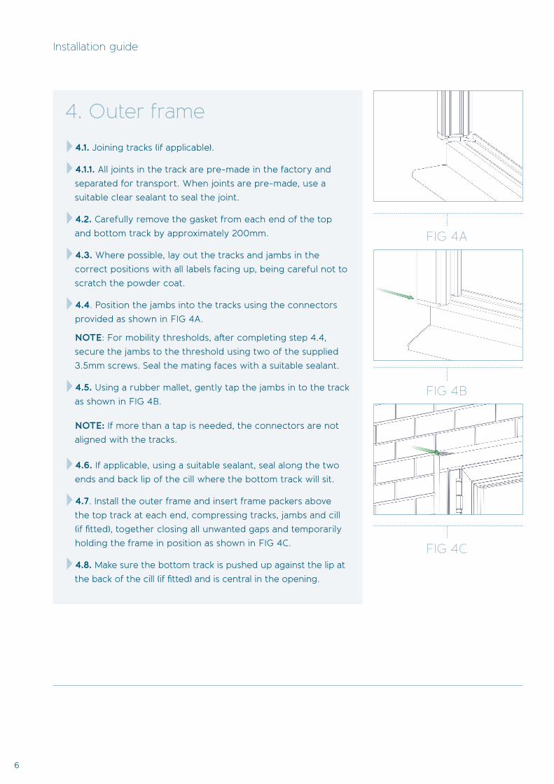
4. Outer frame
4.1. Joining tracks (if applicable).
4.1.1. All joints in the track are pre-made in the factory and separated for transport. When joints are pre-made, use a suitable clear sealant to seal the joint.
4.2. Carefully remove the gasket from each end of the top and bottom track by approximately 200mm.
4.3. Where possible, lay out the tracks and jambs in the correct positions with all labels facing up, being careful not to scratch the powder coat.
4.4. Position the jambs into the tracks using the connectors provided as shown in FIG 4A.
NOTE: For mobility thresholds, after completing step 4.4, secure the jambs to the threshold using two of the supplied 3.5mm screws. Seal the mating faces with a suitable sealant.
4.5. Using a rubber mallet, gently tap the jambs in to the track as shown in FIG 4B. NOTE: If more than a tap is needed, the connectors are not aligned with the tracks.
4.6. If applicable, using a suitable sealant, seal along the two ends and back lip of the cill where the bottom track will sit.
4.7. Install the outer frame and insert frame packers above the top track at each end, compressing tracks, jambs and cill (if fitted), together closing all unwanted gaps and temporarily holding the frame in position as shown in FIG 4C.
4.8. Make sure the bottom track is pushed up against the lip at the back of the cill (if fitted) and is central in the opening.
4A
4B
4C
4B
4C
Installation guide
FIG 4A
FIG 4C
FIG 4B

7
Bi-
fold
Do
ors
5B
5C
5B
5C
FIG 5A
5. Fixing the outer frame
FIG 5B
FIG 5C
5.1. Fix the bottom track and cill as shown in FIG 5A. Position the fixings approximately 100mm in from each end of the track and one fixing every door width along the length. If there is no cill, fix the bottom track to the brick/ block below, making sure it is straight and remains level
5.2. Using a 13mm drill bit, make a hole in the outer layer of polyamide, level with the centre of each jamb packer. This will allow installation of the fixing plug as shown in FIG 5B.
5.3. Using the correct size HSS bit for your preferred fixing, drill through each jamb packer. To protect your drill bit, place a putty knife (or similar) between the jamb packer and brick.
5.4. Align the bottom of the jambs with the end of the bottom track. Using frame packers between the jamb packers and the wall, level out the jambs in all directions and fix into position with your preferred fixings as shown in FIG 5C.
5A

8
5E
FIG 5D
5. Fixing the outer frame continued
FIG 5E
FIG 5F
Installation guide
5.5. Align the end of the top track with the top of the jamb as shown in FIG 5D.
5.6. Install a fixing in the top track approximately 100mm in from the jamb as shown in FIG 5E, being careful not to lift the track from the top of the jamb when the fixing is tightened.
5.7. Using the string line and pinch rod or measuring staff, make sure the track does not bow inside to out, or up and down, as shown in FIG 5F.
5.8. Install the remaining fixings into the top track in line with the bottom track fittings, being careful not to bow or twist the track.
5.9. Trim and reinstall the track gasket.
5D
5F

9
Bi-
fold
Do
ors
6C
6. Top and bottom fork
6.1. Remove the bottom carriage and fork assembly from its packaging, and using a 4mm frame packer, check the ride height is set correctly as shown in FIG 6A.
6.2. Place the bottom carriage and fork assembly into the bottom track as shown in FIG 6B. The fork should point to the outside if the doors are open out, and inside if the doors open in. Repeat this process until all bottom carriage assemblies have been installed.
6.3. Install all top fork guide wheels and move down the track to the opposite end. The thicker side of the wheel should be on top as shown in FIG 6C.
6.4. Insert the top fork between two guide wheels and lower down to locate the pins into them from above, as shown in FIG 6D&E. Repeat this process until all top forks are installed.
6B
6D
6E
FIG 6A
FIG 6B
FIG 6D
FIG 6EFIG 6C
6A

10
7. Door leaves
Installation guide
7.1. Locate the fork pins and bolts from the components bag.
7.2. Hang the first door on the hinge jamb as shown in FIG 7 A&B with the label at the top and facing out.
7.3. Hang the second door onto the hinges of the first door, again with the label at the top and facing out as shown in FIG 7C.
7.4. Close the two doors across the track and lock into place with the slave handle, being careful not to scratch the track as the doors cross it.
7.5. Hang the third door onto the centre hinge and insert a screwdriver through the top hinge; this will support the door whilst the forks are located as seen in FIG 7D.
7.6. With the third door completely open, locate the bottom fork around the bottom hinge between the second and third doors.
7.7. Remove the screw and insert the fork pin into the bottom fork and hinge using a plastic hammer to gently tap the pin in fully, being careful to align the hinge and fork as the pin goes through as shown in FIG 7E.
7.8. Reinstall the screw and tighten using a t30 Torx key.
7.9. Remove the screwdriver from the top hinge and locate the top fork around the hinge.
7.10. Insert the second fork pin bolt as described in points 7.8. and 7.9.
7.11. Repeat steps 7.1 to 7.12 until all door leaves are hung.When closing the master/lead door for the first time, ensure that contact with the locking jamb or stile does not occur. If contact occurs, adjust the doors as described in section 14.
Note

11
Bi-
fold
Do
ors
7D
7A
7E
7B
FIG 7CFIG 7B
FIG 7E
FIG 7A
FIG 7D
7C
12
Installation guide
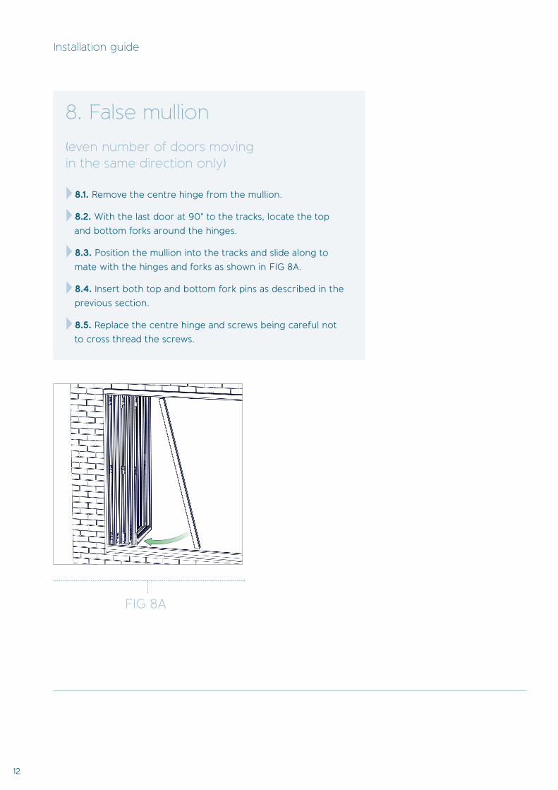
8. False mullion
(even number of doors moving in the same direction only)
8.1. Remove the centre hinge from the mullion.
8.2. With the last door at 90° to the tracks, locate the top and bottom forks around the hinges.
8.3. Position the mullion into the tracks and slide along to mate with the hinges and forks as shown in FIG 8A.
8.4. Insert both top and bottom fork pins as described in the previous section.
8.5. Replace the centre hinge and screws being careful not to cross thread the screws.
8A
FIG 8A

13
Bi-
fold
Do
ors
D-handles (open out only)
Hafi Stainless Steel Handles (separate handle and barrel)
Long Back Plate Lever/ Lever Handles
9.1. Position the D-handle over the centre hinge above the slave handle.
9.2. Fix the handle top and bottom using the D-handle fi xings. These may need a gentle tap to locate the thread.
9. Handles
9.3. Remove the screws from the lever handle, allowing the two halves to be separated.
9.4. Insert the spindle and a return spring (if supplied) into the outer part of the handle. (The outer handle will have the thread for the handle screws).
9.5. Making sure the lever is across the glass, insert the spindle into the lock.
9.6. Locate the handle around the barrel and fl ush against the door.
9.7. Install the internal part of the handle and second return spring (if supplied), again with the lever across the glass.
NOTE: Always keep a hand on the external handle to prevent damage.
NOTE: It may be necessary to slacken the retaining screw on the barrel to help alignment. Always re tighten.
9.8. Install the two screws and carefully tighten with a hand screwdriver only.
9.9. Locate the handles and 4 no. 20mmxM5 screws from the components box.
9.10. Remove the escutcheons from both handles.
9.11. Insert the spindle into one lever and nip the grub screw using a 3mm Allen key.
9.12. Install the handle and spindle into the door with the lever across the glass.
9.13. Insert the 20mm x M5 screws and tighten using a Pozi 2 hand screwdriver only, being careful not to cross thread the screws.
9.14. Install the remaining lever onto the door and secure in place, as described in the previous step and nip the remaining grub screw.
9.15. Install both inner and outer escutcheons with the small cut out pointing down.
NOTE: It may be necessary to use a rubber mallet to gently tap the escutcheons
fully into position.
(Style 253/280) (Style 251/280)
(Style 301/280) (Style 303/280)
Hafi handles
D-handle
14
Installation guide
10. Centre hinge (open in only)
10.1. Open the doors and locate the missing centre hinges.
10.2. Making sure the two halves of the top and bottom hinges are together, install the centre hinge, being careful not to cross thread the screws.
NOTE: All hinges will be found in the
components box.
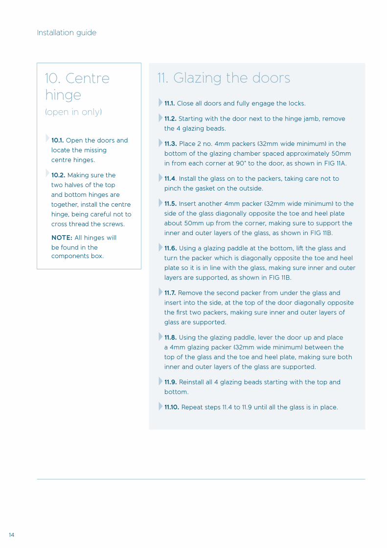
11. Glazing the doors
11.1. Close all doors and fully engage the locks.
11.2. Starting with the door next to the hinge jamb, remove the 4 glazing beads.
11.3. Place 2 no. 4mm packers (32mm wide minimum) in the bottom of the glazing chamber spaced approximately 50mm in from each corner at 90° to the door, as shown in FIG 11A.
11.4. Install the glass on to the packers, taking care not to pinch the gasket on the outside.
11.5. Insert another 4mm packer (32mm wide minimum) to the side of the glass diagonally opposite the toe and heel plate about 50mm up from the corner, making sure to support the inner and outer layers of the glass, as shown in FIG 11B.
11.6. Using a glazing paddle at the bottom, lift the glass and turn the packer which is diagonally opposite the toe and heel plate so it is in line with the glass, making sure inner and outer
layers are supported, as shown in FIG 11B.
11.7. Remove the second packer from under the glass and insert into the side, at the top of the door diagonally opposite the first two packers, making sure inner and outer layers of glass are supported.
11.8. Using the glazing paddle, lever the door up and place a 4mm glazing packer (32mm wide minimum) between the top of the glass and the toe and heel plate, making sure both inner and outer layers of the glass are supported.
11.9. Reinstall all 4 glazing beads starting with the top and bottom.
11.10. Repeat steps 11.4 to 11.9 until all the glass is in place.

15
Bi-
fold
Do
ors
11C
2A
11A
11B
11C
FIG 11A
FIG 11B
FIG 11C
The packer positions will always be set by the location of the toe and heel plate and will be opposite to the adjoining door, as shown in FIG 11C.
If the glass is not square or stepped, it may be necessary to use a thinner packer between the glass and toe and heel plate. These should always be a minimum of 32mm wide.
Notes

16
Installation guide
12. Installing the wedge gasket 12.1. Starting with the bottom bead, use the glazing paddle to gently lever the bead away from the glass and into the correct position whilst lifting the side beads.
12.2. Place the gasket between the glass and bead with the concave side against the glass.
12.3. Feed the gasket behind the side bead until it stops and then continue along the bottom bead compressing the gasket towards the start point.
12.4. Repeat steps 12.1 to 12.3 with the top bead.
12.5. Cut a slight angle on the end of the gasket and insert behind the side bead pushing up to meet the top gasket.
12.6. Continue to feed the gasket along the side bead, compressing towards the starting point.
12.7. Once the bottom is reached, cut the gasket approximately 5mm past the bottom gasket again with a slight angle to meet the bottom gasket.
12.8. Repeat steps 12.5 to 12.7 with the remaining side.
12.9. Repeat steps 12.1 to 12.8 with the remaining doors.
13. Toe and heel adjustment
13.1. If adjustment is needed, you will find a toe and heel device in the top of each door.
13.2. Open the doors so that you can get access to the toe and heel device at the top of the door. Using a 4mm Allen key, wind the bolt clockwise, causing the side of the door to rise.
13.3. Re-close the doors and check that they run parallel and evenly to the top and bottom tracks. If they do not, then repeat as necessary.
13.4. Once you have adjusted the doors, make sure that each toe and heel plate is tight to the glass in each door, this will prevent the doors from settling over time.

17
Bi-
fold
Do
ors
14. Adjustment
14.1. To check the top and bottom tracks are parallel, open all the door leaves completely.
14.2. At this point, the pins in the centre of the top guide wheel should be fairly flush with the visible face of the guide wheel, as shown in FIG 14A. Move the doors along the track whilst monitoring the pins in the top guide wheels. If the top and bottom tracks are parallel, the visible pin should remain the same as at the start.
14.3. If the visible pin decreases at any point, the top track will need repacking to raise it up at these points.
14.4. If the visible pin increases at any point, the top track will need repacking to lower it at these points.
NOTE: The bottom track must be well supported and level for the description above to be correct.
NOTE: All adjustment comes from the outer frame.
Tracks Jambs
14.5. When the lead door is closed, there should be a visible gap of 4mm between itself and the jamb or locking style, adjust as follows if necessary.*
14.6. Remove the two centre fixings from one jamb.
14.7. Remove the top fixing from that jamb.
14.8. Repack the top of the jamb to give a 4mm gap between the edge of the lead door and jamb.
14.9. Replace the fixing in the top of the jamb.
14.10. Remove the bottom fixing from the jamb.
14.11. Repack the bottom of the jamb to give a 4mm gap between the edge of the lead door and jamb.
14.12. Replace the fixing in the bottom of the jamb.
14.13. Pack and replace the remaining two fixings, keeping the even 4mm gap.
14A
FIG 14A
*This is temperature dependent. When installing in particularly hot weather, the gap along the slam and rebate may need reducing slightly. In particularly cold weather, this gap may require increasing slightly. This accounts for the minimal potential expansion and contraction with the aluminium profile.
14A
FIG 14B

18
Installation guide
15. Magnetic keep
15.1 Locate the magnetic keep from the components box.
15.2 Open the lead door almost 180° until the handle is approximately 10mm from the adjoining door and hold
in position.
15.3 Position the complete magnetic keep up between the top of both doors and move along until it is wedged between them, as shown in FIG 15A.
15.4 Using a pencil, mark the magnet holder position on the lead door.
15.5 Close the lead door.
15.6 Return the magnet holder to your mark and move up or down to position in the centre of the door profile. The centre of the hole should be 26mm down from the top of the door.
15.7 Using a 3.5mm drill bit, mark the door through the hole in the magnet holder, as shown in FIG15B.
15.8 Remove the holder and using the 3.5mm drill bit, drill a hole on the previously made mark.
15.9 Install the magnet and cover plate.
15.10 Place the two halves of the magnetic keep together.
15.11 Open the lead door against the adjoining door to locate the second half and mark with a pencil.
15.12 Fix in position as previously described.
15.13 Install cover plate.
15A
15B
FIG 15A
FIG 15B

19
Bi-
fold
Do
ors
16. Finishing touches
16.1 Insert fixing plugs provided into the 13mm holes drilled into the jambs.
16.2. Insert the hinge plugs into the top and bottom of all open hinges.
16.3. We recommend you use expanding foam to fill the gaps between the outer frame and building on all 4 sides.
NOTE: The weather seal around the outer frame to the building is the responsibility of the installer. Sealant and trim kits are available from Origin.
20
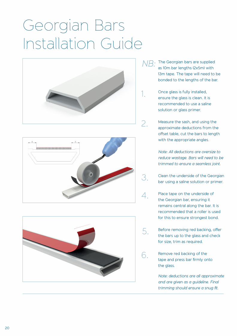
The Georgian bars are supplied as 10m bar lengths (2x5m) with 13m tape. The tape will need to be bonded to the lengths of the bar.
Once glass is fully installed, ensure the glass is clean. It is recommended to use a saline solution or glass primer.
Measure the sash, and using the approximate deductions from the off set table, cut the bars to length with the appropriate angles.
Note: All deductions are oversize to reduce wastage. Bars will need to be trimmed to ensure a seamless joint.
Clean the underside of the Georgian bar using a saline solution or primer.
Place tape on the underside of the Georgian bar, ensuring it remains central along the bar. It is recommended that a roller is used for this to ensure strongest bond.
Before removing red backing, off er the bars up to the glass and check for size, trim as required.
Remove red backing of the tape and press bar fi rmly onto the glass.
Note: deductions are all approximate and are given as a guideline. Final trimming should ensure a snug fi t.
1.
2.
3.
4.
5.
6.
NB:
Georgian Bars Installation Guide
21
Bi-
fold
Do
ors
45°
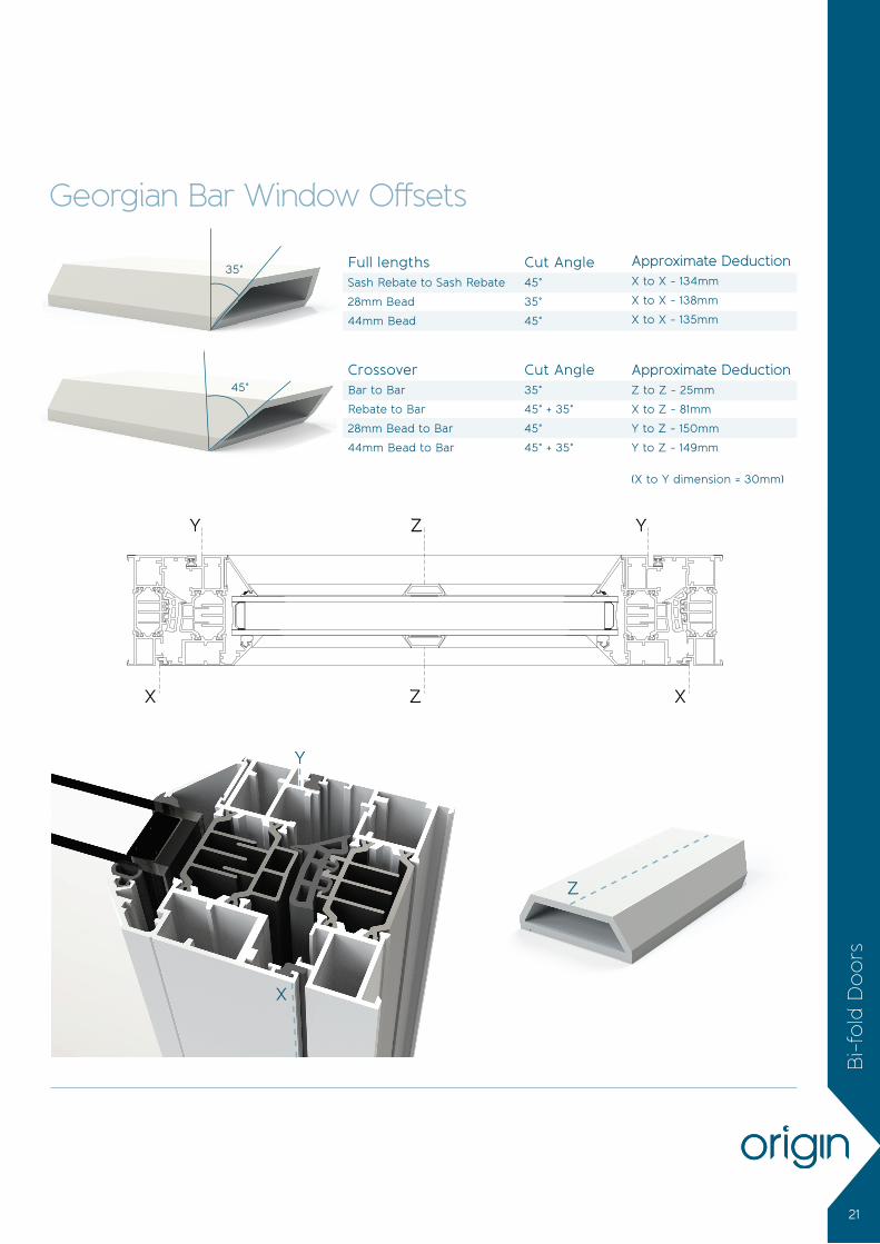
Full lengthsSash Rebate to Sash Rebate
28mm Bead
44mm Bead
CrossoverBar to Bar
Rebate to Bar
28mm Bead to Bar
44mm Bead to Bar
Cut Angle45°
35°
45°
Cut Angle35°
45° + 35°
45°
45° + 35°
Approximate DeductionX to X - 134mm
X to X - 138mm
X to X - 135mm
Approximate DeductionZ to Z - 25mm
X to Z - 81mm
Y to Z - 150mm
Y to Z - 149mm
Georgian Bar Window Off sets
35°
Z
X
Y
X XZ
Y YZ
(X to Y dimension = 30mm)

22
Full lengthsRebate to Rebate
24mm Bead
28mm Bead
CrossoverBar to Bar
Rebate to Bar
24mm Bead to Bar
28mm Bead to Bar
Cut Angle45°
35°
35°
Cut Angle35°
45° + 35°
35°
45° + 35°
Approximate DeductionX to X - 143mm
X to X - 150mm
X to X - 151mm
Approximate DeductionZ to Z - 25mm
X to Z - 84mm
X to Z - 90mm
X to Z - 88mm
Georgian Bar Door Off sets
Z
X
X
ZX X
ZX X
45°
35°
Georgian Bar Installation Guide

23
Bi-
fold
Do
ors
Fit the handle to the sash rebate furthest from the mullion on the last door on the even door set.
Position the handle on the sash rebate so that the centre is 1020mm from the bottom of the sash and fi x as shown below using two 3.9 x 30mm zinc coated self-drilling screws.
1.
2.
Finger Pull HandleInstallation GuideTo be fi tted on open-in even door sets only.
NB: It is recommended that
the glass be removed before
installation to avoid shattering it.

OFDL_18.21.4
Origin Global HQ, Stuart House, Castle Estate, Coronation Road, High WycombeBuckinghamshire, HP12 3TA
t 0808 168 5816 e [email protected] www.origin-global.com
Origin Northern Centre of Excellence,Taurus Park, Europa Boulevard, Westbrook, Warrington, Cheshire, WA5 7ZT
t 01925 907 907e [email protected] w www.origin-global.com
Contact
Accounts
t 08448 802 371 or 01494 416 895 e [email protected]
Marketing
t 08448 802 374 or 01494 416 897 e [email protected]
Sales Operations
t 0808 168 5816 or 01494 686 868 e [email protected]
Solutions
t 08448 802 373 or 01494 416 896 e [email protected]
Fleet and Logistics
t 08448 802 378 or 01494 416 898 e [email protected]