Embed Size (px)
Citation preview

FUSION ACTIVE CONTROL TECHNOLOGY
BLADE ACTIVE MANAGEMENT TECHNOLOGY
Core Alignment Fusion splicer 90S+ kit
Enhanced Splice Quality

Freq
uen
cy
Freq
uen
cy
[dB] [dB]
1. Active Fusion control by cleave condition
2. Active Fusion control by fiber brightness
3. Active Fusion control by fiber discrimination
Fusion is easily affected by changes in the environment. The 90S+ uses real-time fusion parameter control by analyzing the fiber’s brightness intensity during fusion. It contributes to stable, reduced splice loss.
Adequate splice parameters may differ depending on fiber type. The 90S+ automatically applies the optimum splice parameters depending on the fiber type.
FUSION ACTIVE
CONTROL TECHNOLOGY
One of main causes of high splice loss is bad cleave end face. The 90S+ analyzes the condition of both L and R cleave end faces and performs optimal fusion control. This new technology improves splice loss significantly and reduces the risk of re-installation.
θ
Splice loss with large cleave angle : 3 <θ< 5 degree
*G.652 splicing result measured with a cut-back method. The splicing result changes depending on the fiber type and fiber characteristics.
Active Fusion Control Technology
Left:G.652-Right:G.651 G.651
Left:G.652-Right:G.657 G.651

Active Blade Management Technology
Motorized blade
2. Active Blade life management
1. Active Blade rotation by motor The 90S+ and CT50 fiber cleaver are enabled with wireless data connectivity. This capability allows automatic cleaver blade rotation when the 90S+ judges the blade is worn. The 90S+ can connect to two CT50s simultaneously.
The 90S+ displays the remaining blade life and informs the user when a blade height change, position change, or new blade is required.
Replace
BLADE ACTIVE
MANAGEMENT TECHNOLOGY

1,000 cleaves 1,500 cleaves
Large cleave angle
Bad cleave shape
Did not cleave
Example of cleave failure frequency
7
The below graphs show the number of cleaves on the horizontal line with frequency of large cleave angle, bad cleave shape and no cleave at all. When the frequency of large cleave angle increases, Active Blade Management Technology can detect this increasing ratio point and rotate the blade position automatically. Active Blade Management Technology significantly reduces frequency of large cleave angles occurring but even when it does occur Active Fusion Control Technology can reduce high splice loss by precise fusion control. The 90S+ can minimize the occurrence of high splice loss and contribute to reduce the risk of re-Installation by using these 2 key technologies together.
Enhanced Splice Quality

The shape of the sheath clamp is optimized for 60mm length protection sleeves. The length from splice point to the edge of the sheath clamp is 30mm. Therefore, it is easy to center the protection sleeve over the splice by using your fingers to reference the splice point.
The faster automated features of the 90S+ reduce installation times. With this splicer, an operator can complete the entire splice process from splicing to heating without touching the 90S+ and only moving the fiber.
Operation Time Reduction
Automatic Open-Close wind protectors
Automatic heater clamp
Fiber retention clamps
The fiber retention clamps support the automated operations. When the sheath clamps open automatically after splicing, the fiber retention clamps gently hold the spliced fiber to keep it from flying out. The retention clamps release when the fiber is lifted by the operator.
These functions enable the 90S+ to reduce operation time by 50% over the previous model.
Easy centering
Time for operation time
70S+ 90S+
50% lower
1. Automatic Open-Close Wind protectors 3. Fiber retention clamp
4. Operation time reduction
2. Operation time reduction

The newly designed work tray has many functions. There are two drawers for storage which are large enough to store tools or battery packs. Also, the work tray can be divided in two, so it is configurable to fit your work space.
There are multiple ways to utilize the 90S carrying case. The 90S+ is ready to use just by opening the case, but it is also possible to use the 90S+ on top of the carrying case or only with the work tray depending on the work environment.
User Friendly
Open
Ready to use
Lid of carrying case becomes a work tray
Separable Work Tray
Plenty of space
in work tray
Battery packs Cleaver & Stripper
Large storage space under work tray
1. Carrying Case 2. Work Tray

User Friendly
Protrusion for loose tube fiber
70S+ 90S+
Protrusion Switch
Wider Illumination range Protrusion can fix fiber position
3. Loose tube Compatibility 4. Tool-less Electrodes and illumination The sheath clamp of the 90S+ is compatible with loose tube fiber. The Protrusion part on of the sheath clamp for loose tube fiber engages or retracts by simply changing the switch position with your finger.
The 90S+ electrodes come as an “assy” including the fixing screw. You can rotate the screw by hand without tools, enabling easy electrode replacement.
The transparent electrode covers support wider illumination of the v-groove. As the sheath clamp opens on the opposite side of the illumination lamp, the sheath clamp area is illuminated without shadow.
Protrusion Switch Green
Protrusion Switch Red
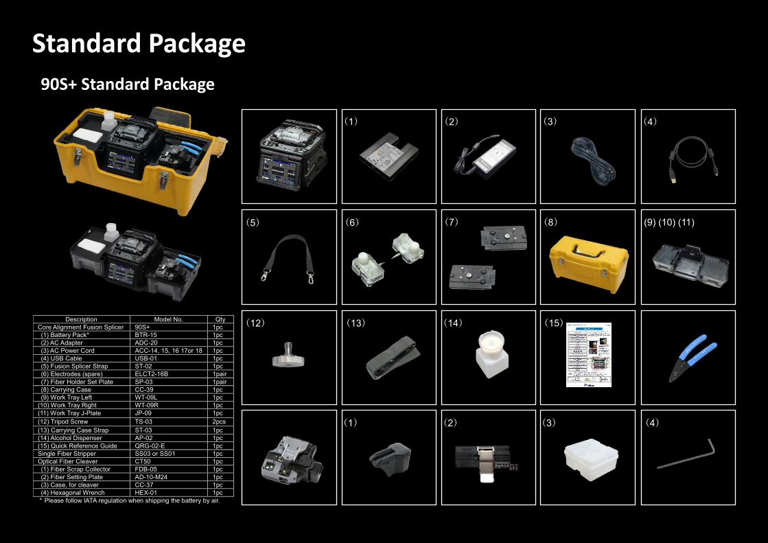
Standard Package
90S+ Standard Package
(1) (2)
(6) (5)
(4) (3)
(14) (13) (12)
(9) (10) (11) (8) (7)
(4) (3) (2) (1)
(15) Description Model No. Qty
Core Alignment Fusion Splicer 90S+ 1pc
(1) Battery Pack* BTR-15 1pc
(2) AC Adapter ADC-20 1pc
(3) AC Power Cord ACC-14, 15, 16 17or 18 1pc
(4) USB Cable USB-01 1pc
(5) Fusion Splicer Strap ST-02 1pc
(6) Electrodes (spare) ELCT2-16B 1pair
(7) Fiber Holder Set Plate SP-03 1pair
(8) Carrying Case CC-39 1pc
(9) Work Tray Left WT-09L 1pc
(10) Work Tray Right WT-09R 1pc
(11) Work Tray J-Plate JP-09 1pc
(12) Tripod Screw TS-03 2pcs
(13) Carrying Case Strap ST-03 1pc
(14) Alcohol Dispenser AP-02 1pc
(15) Quick Reference Guide QRG-02-E 1pc
Single Fiber Stripper SS03 or SS01 1pc
Optical Fiber Cleaver CT50 1pc
(1) Fiber Scrap Collector FDB-05 1pc
(2) Fiber Setting Plate AD-10-M24 1pc
(3) Case, for cleaver CC-37 1pc
(4) Hexagonal Wrench HEX-01 1pc
* Please follow IATA regulation when shipping the battery by air.

Specifications 90S+ Specifications 90S+ Options Item Specification
Fiber alignment method Active core alignment
Fiber count can be spliced Single fiber
Applicable fiber
Fiber type Single mode optical fiber
Multi mode optical fiber
Cladding dia. 80 to 150μm
Applicable coating
Sheath clamp Coating dia. : Max. 3000μm
Cleave length : 5 to 16mm *1
Fiber splice performance
Splice loss *2
ITU-T G.652 : Avg. 0.02dB
ITU-T G.651 : Avg. 0.01dB
ITU-T G.653 : Avg. 0.04dB
ITU-T G.654 : Avg. 0.04dB
ITU-T G.655 : Avg. 0.04dB
ITU-T G.657 : Avg. 0.02dB
Splice time *3 SM FAST mode : Avg. 7 to 9sec.
AUTO mode : Avg. 14 to 16sec.
Applicable protection sleeve
Sleeve type Heat shrinkable sleeve
Sleeve length Max. 66mm
Sleeve dia. Max. 6.0mm before shrinking
Sleeve heat performance
Heat time *4 60mm slim mode : Avg. 9 to 10sec.
60mm mode : Avg. 13 to 15sec.
Fiber tensile test force Approx. 2.0N
Electrode life *5 Approx. 5000 splices
Physical description
Dimensions W Approx.170mm without projection
Dimensions D Approx.173mm without projection
Dimensions H Approx.150mm without projection
Weight Approx. 2.8kg including battery
Environmental condition
Temperature Operate : -10 to 50 degreeC
Storage : -40 to 80 degreeC
Humidity Operate : 0 to 95%RH non-condensing
Storage : 0 to 95%RH non-condensing
Altitude Max. 5000m
AC adaptor Input AC100 to 240V, 50/60Hz, Max. 1.5A
Battery pack
Type Rechargeable Lithium Ion
Output Approx. DC14.4V, 6380mAh
Capacity *6 Approx. 300 splice and heat cycles
Temperature Recharge : 0 to 40 degreeC
Storage : -20 to 30 degreeC
Battery life *7 Approx. 500 recharge cycles
Display LCD monitor TFT 4.9 inches with touch screen
Magnification 200 to 320x
Illumination V-grooves LED lamp
Interface
PC USB2.0 Mini B type
External LED lamp
USB2.0 A type Approx. DC5V, 500mA
Ribbon Stripper Mini DIN 6pin DC12V, Max. 1A
Wireless *8 Bluetooth 4.1 LE
Data storage
Splice mode 100 splice modes
Heat mode 30 heat modes
Splice result 20000 splices
Splice image 100 images
Screw hole for tripod 1/4-20UNC
Other features
Automatic functions
Splice mode selected using fiber type analysis
Fusion power calibration
Wind protector : open and close
Sheath clamp : open
Heater lid : open and close
Heater clamp : open and close
Reference guide Video and PDF file stored in splicer
Sheath clamp Easy sleeve positioning clamp
Electrode Replaceable without tool
Item Model Remark
Fiber holder
FH-70-200 200μm coating diameter
FH-70-250 250μm coating diameter
FH-70-900 900μm coating diameter
FH-FC-20 900μm in 2mm diameter cable
FH-FC-30 900μm in 3mm diameter cable
DC Adapter DCA-03 Connect AC adapter not through battery
DC power cord DCC-20 Car cigar socket to BTR-15/DCA-03
DCC-21 Car battery to BTR-15/DCA-03
Transfer Clamp CLAMP-DC-12 Transferring drop cable on work tray
J-Plate JP-10 Attaching to splicer, not to work tray
JP-10-FC JP-10 with fiber clamps
Protection sleeve
FP-03 60mm, Max. 900μm coating diameter
FP-03(L=40) 40mm, Max. 900μm coating diameter
FP-03M FP-03 with non-magnetic material
Notes *1 Cleave length range depending on fiber type 5 to 16mm : 125μm cladding dia. and 250μm coating dia. 10 to 16mm : 125μm cladding dia. and 400 or 900μm coating dia. 5 to 10mm : 80μm cladding dia. and 160μm coating dia. 5 to 16mm : 150μm cladding dia. and 250μm coating dia. *2 Measured with a cut-back method relevant to ITU-T and IEC standard after splicing Fujikura
identical fibers. The average splice loss changes depending on the environmental condition and fiber characteristics.
*3 Measured at room temperature. The definition of splice time is from the fiber image appearing on LCD monitor to the estimated loss displayed. The average splice time changes depending on the environmental conditions, fiber type, and fiber characteristics.
*4 Measured at room temperature with the AC adapter. The heat time is defined from the start beep sound to the finish beep sound. The average heat time changes depending on the environmental conditions, sleeve type and battery pack condition.
*5 The electrode life changes depending on the environmental conditions, fiber type and splice modes.
*6 Test condition (1) Splice and heat time : 1 minute cycle (2) Using the splicer power save settings (3) Using a not degraded battery (4) At room temperature The battery capacity changes when testing with different conditions from the above.
*7 The battery capacity decreases to a half after approx. 500 discharge and recharge cycles, The battery life is shortened further when using outside of the storage temperature range, operating temperature range, if completely discharged by storing for a long time without recharging.
*8 Bluetooth® mark and logos are the registered trademarks of Bluetooth SIG, Inc.

Specifications
CT50 Specifications CT50 Options Item Model Remark
Fiber Setting Plate
AD-50 Optional fiber setting plate
Blade CB-08 Blade for replacement
Clamp Arm ARM-CT50-01 Clamp arm with anvil for replacement
Fiber Scrap Collector
FDB-05 Spare scrap collector
Side cover SC-CT50-01 Side cover instead of scrap collector
Spacer
SPA-CT08-10 Cleave length 10mm
SPA-CT08-09 Cleave length 9mm
SPA-CT08-08 Cleave length 8mm
Fujikura Ltd. 1-5-1, Kiba, Koto-ku, Tokyo 135-8512, JapanGeneral inquiries : +81-3-5606-1164 Service & support : +81-43-484-3962 https://www.fujikura.com
91330-2104-0074-01 Specifications and descriptions are subject to change without prior notice. Ⓒ 2021 Fujikura Ltd.
Item Specification
Applicable fiber
Fiber type Single mode optical fiber
Multi mode optical fiber
Fiber count Up to 16 fiber ribbon
Cladding dia. Approx. 125μm
Applicable coating
Fiber setting plate
AD-10-M24 : Max. 900µm coating diameter
AD-50 : Max. 3mm coating diameter
Fiber holder Coating shape. : Refer to splicer options
Cleave length
Fiber setting plate
AD-10-M24 : 5 to 20mm *1
AD-50 *C.D. : coating diameterC.D. = 250µm or less : 5 to 20mm *1 250µm < C.D. < =900µm : 10 to 20mm900µm < C.D. < =3mm : 14 to 20mm
Fiber holder Approx. 10mm
Cleave angle *2 Single fiber Avg. 0.3 to 0.9 degrees
Fiber ribbon Avg. 0.3 to 1.2 degrees
Blade life *3 Approx. 60000 fiber cleaves
Physical description
Dimensions W Approx. 117mm without projection *4
Dimensions D Approx. 94mm without projection *4
Dimensions H Approx. 59mm without projection *4
Weight Approx. 306g including battery and AD-10-M24
Environmental condition
Temperature Operate : -10 to 50 degreeC
Storage : -40 to 80 degreeC
Humidity Operate : 0 to 95%RH non-condensing
Storage : 0 to 95%RH non-condensing
Battery 2 pieces of LR03, AAA dry battery
Wireless interface *5 Bluetooth 4.1 LE
Screw hole for tripod 1/4-20UNC
Other features
Blade rotation Motorized rotation
Manual rotation dial
Replaceable parts
Blade
Clamp arm
Notes *1 When the cleave length is less than 10mm, the coating diameter should be
250µm or less. Also, a blade height adjustment is required before cleaving. The average cleave angle is worse than the specification when the cleave length is less than10mm.
*2 Measured with an interferometer at room temperature, not with a splicer. A new blade was used to cleave both the single fibers and ribbon fibers. The averagecleave angle changes depending on the environmental conditions, blade condition, operating method, and cleanliness.
*3 The blade life changes depending on the environmental conditions, operating method, and the fiber type cleaved.
*4 Measured in a condition when closing the lever.*5 Bluetooth® mark and logos are the registered trademarks of Bluetooth SIG, Inc.
Visit our web site!
www.opternus.de/lwl-produkte/spleisstechnik/spleissgeraete/
C51 Barwell Business Park, Leatherhead Road, Chessington, Surrey, KT9 2NY, UK General inquiries : +44-20-8240-2000 Service & support : +44-20-8240-2020 https://www.fujikura.co.uk
Fujikura Europe Ltd. Bahnhofstraße 5, 22941 Bargteheide, Deutschland Offizieller Distributor und Servicepartner für Deutschland, Österreich und Luxemburg Tel.: +49 (0) 4532-2044-100, [email protected], https://www.opternus.de Opternus GmbH