Embed Size (px)
Citation preview

1Motorola Optoelectronics Device Data
" ! ! (400 Volts Peak)
The MOC3020 Series consists of gallium arsenide infrared emitting diodes,optically coupled to a silicon bilateral switch.
• To order devices that are tested and marked per VDE 0884 requirements, thesuffix ”V” must be included at end of part number. VDE 0884 is a test option.
They are designed for applications requiring isolated triac triggering.
Recommended for 115/240 Vac(rms) Applications:
• Solenoid/Valve Controls • Static ac Power Switch
• Lamp Ballasts • Solid State Relays
• Interfacing Microprocessors to 115 Vac Peripherals • Incandescent Lamp Dimmers
• Motor Controls
MAXIMUM RATINGS (TA = 25°C unless otherwise noted)
Rating Symbol Value Unit
INFRARED EMITTING DIODE
Reverse Voltage VR 3 Volts
Forward Current — Continuous IF 60 mA
Total Power Dissipation @ TA = 25°CNegligible Power in Triac Driver
Derate above 25°C
PD 100
1.33
mW
mW/°C
OUTPUT DRIVER
Off–State Output Terminal Voltage VDRM 400 Volts
Peak Repetitive Surge Current(PW = 1 ms, 120 pps)
ITSM 1 A
Total Power Dissipation @ TA = 25°CDerate above 25°C
PD 3004
mWmW/°C
TOTAL DEVICE
Isolation Surge Voltage(1)
(Peak ac Voltage, 60 Hz, 1 Second Duration)VISO 7500 Vac(pk)
Total Power Dissipation @ TA = 25°CDerate above 25°C
PD 3304.4
mWmW/°C
Junction Temperature Range TJ –40 to +100 °C
Ambient Operating Temperature Range(2) TA –40 to +85 °C
Storage Temperature Range(2) Tstg –40 to +150 °C
Soldering Temperature (10 s) TL 260 °C
1. Isolation surge voltage, VISO, is an internal device dielectric breakdown rating.1. For this test, Pins 1 and 2 are common, and Pins 4, 5 and 6 are common.2. Refer to Quality and Reliability Section in Opto Data Book for information on test conditions.
Preferred devices are Motorola recommended choices for future use and best overall value.GlobalOptoisolator is a trademark of Motorola, Inc.
Order this documentby MOC3020/D
SEMICONDUCTOR TECHNICAL DATA
GlobalOptoisolator
Motorola, Inc. 1995
*Motorola Preferred Device
SCHEMATIC
[IFT = 15 mA Max]
STANDARD THRU HOLECASE 730A–04
[IFT = 10 mA Max]
[IFT = 5 mA Max]
1. ANODE2. CATHODE3. NC4. MAIN TERMINAL5. SUBSTRATE5. DO NOT CONNECT6. MAIN TERMINAL
1
2
3
6
5
4
61
STYLE 6 PLASTIC
REV 1

2 Motorola Optoelectronics Device Data
ELECTRICAL CHARACTERISTICS (TA = 25°C unless otherwise noted)
Characteristic Symbol Min Typ Max Unit
INPUT LED
Reverse Leakage Current(VR = 3 V)
IR — 0.05 100 µA
Forward Voltage(IF = 10 mA)
VF — 1.15 1.5 Volts
OUTPUT DETECTOR (IF = 0 unless otherwise noted)
Peak Blocking Current, Either Direction(Rated VDRM(1))
IDRM — 10 100 nA
Peak On–State Voltage, Either Direction(ITM = 100 mA Peak)
VTM — 1.8 3 Volts
Critical Rate of Rise of Off–State Voltage (Figure 7, Note 2) dv/dt — 10 — V/µs
COUPLED
LED Trigger Current, Current Required to Latch Output(Main Terminal Voltage = 3 V(3)) MOC3021
MOC3022MOC3023
IFT———
8——
15105
mA
Holding Current, Either Direction IH — 100 — µA
1. Test voltage must be applied within dv/dt rating.2. This is static dv/dt. See Figure 7 for test circuit. Commutating dv/dt is a function of the load–driving thyristor(s) only.3. All devices are guaranteed to trigger at an IF value less than or equal to max IFT. Therefore, recommended operating IF lies between max3. IFT (15 mA for MOC3021, 10 mA for MOC3022, 5 mA for MOC3023) and absolute max IF (60 mA).
–800
TYPICAL ELECTRICAL CHARACTERISTICS
TA = 25°C
Figure 1. LED Forward Voltage versus Forward Current
2
1.8
1.6
1.4
1.2
11 10 100 1000
IF, LED FORWARD CURRENT (mA)
V F, F
ORW
ARD
VO
LTAG
E (V
OLT
S)
85°C
25°C
Figure 2. On–State Characteristics
–3VTM, ON–STATE VOLTAGE (VOLTS)
I
–400
0
+400
+800
–2 –1 0 1 2 3
TM, O
N-S
TATE
CU
RR
ENT
(mA)
TA = –40°C
PULSE ONLYPULSE OR DC
3Motorola Optoelectronics Device Data
TA, AMBIENT TEMPERATURE (°C)– 40
100
1– 30 – 20 –10 0 10 20 30 40 50 60 70 80
10
I DR
M, L
EAKA
GE
CU
RR
ENT
(nA)
0.7
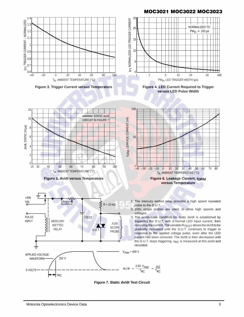
Figure 3. Trigger Current versus Temperature
–40
TA, AMBIENT TEMPERATURE (°C)
0.8
1.1
1.3
1.4
–20 0 20 40 60 80
FTI
0.6100
5
1
PWin, LED TRIGGER WIDTH (µs)
10
15
20
25
2 5 2010 500
100
FTI, N
OR
MAL
IZED
LED
TR
IGG
ER C
UR
REN
T
NORMALIZED TO:PWin 100 µs
Figure 4. LED Current Required to Triggerversus LED Pulse Width
2
40
TA, AMBIENT TEMPERATURE (°C)
4
6
8
10
25 30 50 7060 800
10090
12
STATIC dv/dtCIRCUIT IN FIGURE 7
Figure 5. dv/dt versus Temperature
+400Vdc
PULSEINPUT MERCURY
WETTEDRELAY
RTEST
CTEST
R = 10 kΩ
X100SCOPEPROBED.U.T.
APPLIED VOLTAGEWAVEFORM 252 V
0 VOLTSRC
Vmax = 400 V
dvdt 0.63 Vmax
RC
252RC
1. The mercury wetted relay provides a high speed repeatedpulse to the D.U.T.
2. 100x scope probes are used, to allow high speeds andvoltages.
3. The worst–case condition for static dv/dt is established bytriggering the D.U.T. with a normal LED input current, thenremoving the current. The variable RTEST allows the dv/dt to begradually increased until the D.U.T. continues to trigger inresponse to the applied voltage pulse, even after the LEDcurrent has been removed. The dv/dt is then decreased untilthe D.U.T. stops triggering. RC is measured at this point andrecorded.
, TR
IGG
ER C
UR
REN
T –
NO
RM
ALIZ
ED
0.9
1
1.2
µdv
/dt,
STAT
IC (V
/s)
Figure 6. Leakage Current, I DRMversus Temperature
Figure 7. Static dv/dt Test Circuit

4 Motorola Optoelectronics Device Data
Rin 1
2
6
4
360
MOC3021/3022/3023
470
0.05 µF
Figure 8. Typical Application Circuit
3
5
0.01 µF
39
HOT
240VAC
GROUNDLOAD
VCC
* This optoisolator should not be used to drive a load directly. It is in-tended to be a trigger device only.
In this circuit the “hot” side of the line is switched and theload connected to the cold or ground side.
The 39 ohm resistor and 0.01 µF capacitor are for snub-bing of the triac, and the 470 ohm resistor and 0.05 µF ca-pacitor are for snubbing the coupler. These componentsmay or may not be necessary depending upon the particu-lar triac and load used.
Additional information on the use of optically coupled triacdrivers is available in Application Note AN–780A.

5Motorola Optoelectronics Device Data
PACKAGE DIMENSIONS
CASE 730A–04ISSUE G
NOTES:1. DIMENSIONING AND TOLERANCING PER ANSI
Y14.5M, 1982.2. CONTROLLING DIMENSION: INCH.3. DIMENSION L TO CENTER OF LEAD WHEN
FORMED PARALLEL.
6 4
1 3
–A–
–B–
SEATINGPLANE
–T–
4 PLF
K
CN
G
6 PLD6 PLE
MAM0.13 (0.005) B MT
L
M
6 PLJMBM0.13 (0.005) A MT
DIM MIN MAX MIN MAXMILLIMETERSINCHES
A 0.320 0.350 8.13 8.89B 0.240 0.260 6.10 6.60C 0.115 0.200 2.93 5.08D 0.016 0.020 0.41 0.50E 0.040 0.070 1.02 1.77F 0.010 0.014 0.25 0.36G 0.100 BSC 2.54 BSCJ 0.008 0.012 0.21 0.30K 0.100 0.150 2.54 3.81L 0.300 BSC 7.62 BSCM 0 15 0 15 N 0.015 0.100 0.38 2.54
STYLE 6:PIN 1. ANODE
2. CATHODE3. NC4. MAIN TERMINAL5. SUBSTRATE6. MAIN TERMINAL
CASE 730C–04ISSUE D
–A–
–B–
SEATINGPLANE
–T–J
K
L
6 PL
MBM0.13 (0.005) A MT
C
D 6 PL
MAM0.13 (0.005) B MT
H
GE 6 PL
F 4 PL
31
46
NOTES:1. DIMENSIONING AND TOLERANCING PER ANSI
Y14.5M, 1982.2. CONTROLLING DIMENSION: INCH.
DIM MIN MAX MIN MAXMILLIMETERSINCHES
A 0.320 0.350 8.13 8.89B 0.240 0.260 6.10 6.60C 0.115 0.200 2.93 5.08D 0.016 0.020 0.41 0.50E 0.040 0.070 1.02 1.77F 0.010 0.014 0.25 0.36G 0.100 BSC 2.54 BSCH 0.020 0.025 0.51 0.63J 0.008 0.012 0.20 0.30K 0.006 0.035 0.16 0.88L 0.320 BSC 8.13 BSCS 0.332 0.390 8.43 9.90
*Consult factory for leadform option availability

6 Motorola Optoelectronics Device Data
*Consult factory for leadform option availability
NOTES:1. DIMENSIONING AND TOLERANCING PER ANSI
Y14.5M, 1982.2. CONTROLLING DIMENSION: INCH.3. DIMENSION L TO CENTER OF LEAD WHEN
FORMED PARALLEL.
CASE 730D–05ISSUE D
6 4
1 3
–A–
–B–
N
C
KG
F 4 PL
SEATING
D 6 PL
E 6 PL
PLANE
–T–
MAM0.13 (0.005) B MT
L
J
DIM MIN MAX MIN MAXMILLIMETERSINCHES
A 0.320 0.350 8.13 8.89B 0.240 0.260 6.10 6.60C 0.115 0.200 2.93 5.08D 0.016 0.020 0.41 0.50E 0.040 0.070 1.02 1.77F 0.010 0.014 0.25 0.36G 0.100 BSC 2.54 BSCJ 0.008 0.012 0.21 0.30K 0.100 0.150 2.54 3.81L 0.400 0.425 10.16 10.80N 0.015 0.040 0.38 1.02
Motorola reserves the right to make changes without further notice to any products herein. Motorola makes no warranty, representation or guarantee regardingthe suitability of its products for any particular purpose, nor does Motorola assume any liability arising out of the application or use of any product or circuit,and specifically disclaims any and all liability, including without limitation consequential or incidental damages. “Typical” parameters can and do vary in differentapplications. All operating parameters, including “Typicals” must be validated for each customer application by customer’s technical experts. Motorola doesnot convey any license under its patent rights nor the rights of others. Motorola products are not designed, intended, or authorized for use as components insystems intended for surgical implant into the body, or other applications intended to support or sustain life, or for any other application in which the failure ofthe Motorola product could create a situation where personal injury or death may occur. Should Buyer purchase or use Motorola products for any suchunintended or unauthorized application, Buyer shall indemnify and hold Motorola and its officers, employees, subsidiaries, affiliates, and distributors harmlessagainst all claims, costs, damages, and expenses, and reasonable attorney fees arising out of, directly or indirectly, any claim of personal injury or deathassociated with such unintended or unauthorized use, even if such claim alleges that Motorola was negligent regarding the design or manufacture of the part.Motorola and are registered trademarks of Motorola, Inc. Motorola, Inc. is an Equal Opportunity/Affirmative Action Employer.
How to reach us:USA / EUROPE: Motorola Literature Distribution; JAPAN : Nippon Motorola Ltd.; Tatsumi–SPD–JLDC, Toshikatsu Otsuki,P.O. Box 20912; Phoenix, Arizona 85036. 1–800–441–2447 6F Seibu–Butsuryu–Center, 3–14–2 Tatsumi Koto–Ku, Tokyo 135, Japan. 03–3521–8315
MFAX: [email protected] – TOUCHTONE (602) 244–6609 HONG KONG: Motorola Semiconductors H.K. Ltd.; 8B Tai Ping Industrial Park, INTERNET: http://Design–NET.com 51 Ting Kok Road, Tai Po, N.T., Hong Kong. 852–26629298
MOC3020/D
◊

This datasheet has been download from:
www.datasheetcatalog.com
Datasheets for electronics components.

- 1 - - when you need to be sure...
pHTheory and Practice

- 2 -
Preface
The importance of pH
Many of nature's processes are highly dependent on pH. This is also thecase for the chemical reactions which take place in industry or in a labo-ratory. In 1909, the founder of the modern pH concept, S.P.L. Sørensen,proved that pH is essential for many enzymatic processes. One exampleis the cleavage of cane sugar using invertase.
pH can also have an influence on the colour of certain dyestuffs. For ex-ample, although cyanidin chloride gives the cornflower its blue hue, it isthe same dyestuff which gives a rose its red colour. The explanation isthat cyanidin chloride is blue at a high pH while it is red at a low pH.
It is essential as regards living organisms that the pH of the biologicalfluids is maintained within a narrow pH range.
Swimming pool water is disinfected using a chlorine compound. The chlo-rine's optimal effectiveness and the avoidance of eye irritation can onlybe assured at a specific pH level.
In galvanic baths, quality and current efficiency is critically dependent onthe correct pH. When the residual metals in the rinse water from suchbaths are precipitated, pH also plays a very important role.
These few though wide-ranging examples illustrate the importance of pH.It is appropriate to mention at this point that it is the pH value which is ofsignificance and therefore not the total concentration of acid or alkalinespecies.
The booklet
The subject of this booklet is the potentiometric measurement of pH.This is the way in which pH is defined and is the optimal method for ob-taining precise results. Reliable and accurate measurements depend ona number of factors: the quality of the equipment used, the electrodetype, the accuracy of the calibration, the maintenance level, good labora-tory practice and so forth.
The scope of this booklet is to discuss these various factors and theirimportance. Hints and recommendations are given and short theoreticalsections are included. All the necessary information is therefore at handto help you to obtain precision results in practice.

- 3 -
Contents
Definition of pH ....................................................................................... 4
pH measurements ................................................................................... 5
Electrode types ..................................................................................... 10
Choosing the right electrode .................................................................. 13
Electrode maintenance.......................................................................... 15
The pH meter ........................................................................................ 19
Buffers .................................................................................................. 21
Calibration ............................................................................................. 23
Temperature influence ........................................................................... 24
Measuring precautions .......................................................................... 26
Checking the meter ............................................................................... 27
Appendix ............................................................................................... 28
References ........................................................................................... 33
- 4 -
Definition of pH
pH is an abbreviation of “pondus hydrogenii” and was proposed by theDanish scientist S.P.L. Sørensen in 1909 in order to express the verysmall concentrations of hydrogen ions.
In 1909, pH was defined as the negative base 10 logarithm of the hydro-gen ion concentration. However, as most chemical and biological reac-tions are governed by the hydrogen ion activity, the definition wasquickly changed. As a matter of fact, the first potentiometric methodsused actually resulted in measurements of ion activity.
The definition based on hydrogen ion activity is the definition we use to-day:
pH = - log10aH+
This definition is closely related to the operational pH definition which iscurrently defined using a standardised hydrogen electrode setup andbuffers standardised in accordance with IUPAC recommendations.
Fig. 1. MeterLab® - the complete pH measuring setup

- 5 -
pH measurements
The electrode chain
pH is measured using a setup with two electrodes: the indicator elec-trode and the reference electrode. These two electrodes are often com-bined into one - a combined electrode.
When the two electrodes are immersed in a solution, a small galvaniccell is established. The potential developed is dependent on both elec-trodes.
Ideal measuring conditions exist when only the potential of the indicatorelectrode changes in response to varying pH, while the potential of thereference electrode remains constant.
The measured voltage can be expressed by the Nernst equation in thefollowing way:
E = Eind - Eref = E'T - R • T/F • ln aH+
where
E = Measured voltage (mV)
Eind = Voltage of indicator electrode (mV)
Eref = Voltage of reference electrode (mV)
E'T = Temperature dependent constant (mV)
R = Gas Constant (8.3144 J/K)
T = Absolute Temperature (K)
F = Faraday's constant (96485 C)
By using the base ten logarithm, the formula can be written as:
E = E'T - 2.303 • R • T/F • log aH+
By introducing the pH definition as pH = -log aH+, pH can be expressed atthe temperature T as follows:
pHT = pHT° - ER' • S • T

- 6 -
where
R' = constant = 0.1984 mV/K
S = sensitivity, a correction factor which takes into accountthat the electrode response may differ from the theoreticalvalue.
pH° = zero pH which is defined as the pH value at which themeasured potential is zero. Figure 2 illustrates that the pH°will change with temperature and that another slope will beobserved.
Fig. 2. The mV/pH relation at two different temperatures

- 7 -
Electrode construction
The construction of glass indicator electrodes and reference electrodescan be made in various ways. A typical glass electrode and a typicalcalomel reference electrode are shown below.
Fig. 3. Typical electrode constructions
Salt-bridgesolution
'Red Rod'Referenceelement
Crystals
Filling hole
Porous pin
Shield
Red Rod inner
electrode encap-
sulated by red
glass tube
Inner buffer
solution
saturated with KCl
pH sensitive
glass bulb
Glass electrode Reference electrode

- 8 -
Both the composition of the glass electrode's pH-sensitive glass andthe composition of the glass electrode's inner solution have an influenceon the potential which will develop.
The response of the electrode is the voltage developed between the in-side and outside of the membrane. This voltage is proportional to the dif-ference in pH in the inner solution and in the sample. The response iscaused by an exchange at both surfaces of the swollen membrane be-tween the ions of the glass and the H+ ions of the solution - an ion ex-change which is controlled by the concentration of H+ in both solutions.As the structure of the glass membrane may not be uniform, an asym-metry potential may develop even if pH is the same on both sides.
The reference electrode shown on the previous page is a saturated sil-ver/silver chloride electrode (Ag/AgCl) where the two components andthe KCl are encapsulated in a red tube. The red tubing affords protectionfrom the harmful effects of light. Contact with the chamber is made bymeans of a platinum wire and the Ag/AgCl is surrounded by a saturatedsolution of KCl. The liquid junction, i.e. contact to the measuring solu-tion, is achieved through a porous ceramic pin. The potential which oc-curs is determined by the solubility product of the silver chloride and theconcentration of the KCl solution and is therefore constant.
A similar electrode construction can be made using mercury andmercurous chloride (calomel) instead. Such electrodes are not suitablefor varying temperatures or temperatures above 60°C.
The potential of the reference electrode should be independent of thesample solution. This ideal situation will occur if all transport in the po-rous pin only involves the K+ and Cl- ions, and if they move at the samespeed. This is the case in most samples in the pH range 1 to 13 andwhen a saturated or 3 M KCl salt-bridge solution is used. Deviation fromthis optimal situation creates the so-called liquid junction potential.
Red Rod electrodes should always used saturated KCl.
Table 1 lists the liquid junction potentials in different samples obtainedwith saturated KCl as the salt-bridge solution. The liquid junction poten-tial's dependence on sample composition and especially on pH is obvi-ous.

- 9 -
Table 1. Liquid junction potentials in different samples
The table below shows the equivalent conductivity in infinitely diluted so-lutions (λ) of the ions commonly used in salt-bridge solutions. Equal con-ductivity of the cation and anion, used as a measure of their mobility, re-sults in the lowest liquid junction potentials.
Cation λλλλλ Anion λλλλλ
Li+ 38.7 CH3COO- 40.9
Na+ 50.1 ClO4- 67.4
K+ 73.5 NO3- 71.5
NH4+ 73.6 Cl- 76.4
Br- 78.11/2 SO4
- - 80.0
H+ 349.8 OH- 198.3
Table 2. Equivalent conductivity of ionsin infinite dilutions (S • cm2/equivalent) at 25°C
Sample Liquid Junction Potential
1M HCl 14.1 mV
0.1M HCl 4.6 mV
0.01M HCl 3.0 mV
0.1M KCl 1.8 mV
pH 1.68 buffer 3.3 mV
pH 4.01 buffer 2.6 mV
pH 4.65 buffer 3.1 mV
pH 7.00 buffer 1.9 mV
pH 10.01 buffer 1.8 mV
0.01M NaOH 2.3 mV
0.1M NaOH -0.4 mV
1M NaOH -8.6 mV

- 10 -
Electrode types
Fig. 4. Different glass electrodes for different applications
Glass electrodes
The types shown in Figure 4 are examples of glass electrodes. However,glass electrodes are available in a number of different shapes andlengths to fit a wide range of applications. There are very thin electrodes,spear types, electrodes with a flat membrane for surface measurementsand so forth. The shape, size and type of the inner electrode can vary,as can the glass composition of the membrane. The composition of thepH-sensitive glass will, to a large extent, determine the electrode's re-sponse time and its sensitivity to ions other than H+. Sodium and lithiumions and, to a lesser extent, potassium ions, may interfere at high pHvalues (> pH 11). This is normally called the salt or alkaline error. Ifthere is an abundance of sodium ions and few hydrogen ions, they maypenetrate into the swollen glass surface layer. This means that the elec-trode will sense a higher ion concentration and therefore a pH valuewhich is too low will be obtained by the pH meter.
Two disadvantages of glass electrodes are that measuring solutions candamage the glass membrane and that the glass membrane is easily bro-ken. Alternatives to the glass electrode are available but are seldomused as they have other drawbacks, e.g. a long response time. The anti-mony electrode is the most widely used alternative. The thin oxide layerformed on the surface of the antimony metal is sensitive to pH.

- 11 -
Reference electrodes
A number of different reference electrodes are available. These varia-tions relate to:
• the physical construction of the liquid junction
• the composition of the salt-bridge solution
• the electrode's electrochemical composition
The most common type of liquid junction is formed by a porous pin.However, depending on the application, other types can be used: circularceramic junctions, sleeve junctions or an open junction through a thinglass tube. These will ensure a higher outflow of salt-bridge solutionwhich is beneficial when measuring in solutions of very high or very lowionic strength. Certain buffers and samples, for example, tris buffer andslurry also require these types of liquid junctions.
Four different liquid junctions are shown in Fig. 5. The typical outflow ofKCl salt-bridge solution for each type is also stated.
Fig. 5. Liquid junction constructions with typical KCl outflow
< 10 µl/h
FibrePorous pin Double junction Annular Reversed sleeve
10 µl/h 10 µl/h 10-100 µl/h 1 ml/h

- 12 -
KCl should not be used as the salt-bridge solution if:
• it will interfere with the measuring solution
• if there is a risk that the liquid junction will become blocked dueto precipitation
• if it is immiscible with the sample.
Two alternatives are available: a double junction system, i.e. with a sec-ond salt-bridge which does not contain KCl, or a modified electrode sys-tem can be used. A system with mercurous sulfate and potassiumsulfate is one example. An overview of some of the combinations is pro-vided in Table 3.
Type of Salt- Potential vs. Potential vs.reference bridge standard H2 sat. calomelelectrode solution(s) electrode electrode
Hg/Hg2Cl2 sat. KCl 244 mV 0 mV
Ag/AgCl sat. KCl 200 mV - 44 mV
Hg/Hg2SO4 sat. K2SO4 640 mV 408 mV
Calomel sat. LiCl ~ 200 mV ~ - 45 mV
Hg/Hg2Cl2 sat. KCl/KNO3 244 mV ~ 0 mV
Table 3. Potentials for different reference electrodes
Combined electrodes
Since it is easier to handle one electrode instead of two, combined elec-trodes (single stem) are very popular. The indicating glass electrode andthe reference electrode are simply built into a single physical entity. Thishelps to ensure that the two electrodes have the same temperature dur-ing operation.
Combined electrodes with symmetrical electrode chains are the optimalconstruction for obtaining temperature equality in the two electrodes. Inthese electrodes the inner electrode of the glass electrode is the sametype (Ag/AgCl) and has the same dimensions as the reference electrode,and the inner solutions are as identical as possible (saturated with KCl).

- 13 -
Choosing the right electrode
Choosing the right physical dimensions is straightforward as the samplesize and sample vessel will dictate the type you should use. If the elec-trodes are to be used under harsh conditions, types with a plastic stemand protection cap will be suitable. Measurements which are to be per-formed directly on a surface require a flat electrode and so forth.
Fig. 6. Selection of the correct reference electrodefor different measuring conditions

- 14 -
Measurements at high temperatures restrict your choice of electrodes asonly certain electrochemical systems can withstand higher temperatures.Calomel electrodes, for example, cannot withstand temperatures above60°C. However, certain Ag/AgCl reference electrodes can be used in-stead. The temperature range used may also be restricted depending onwhat the electrode is made of. Low temperature prolongs the responsetime of the electrodes. Long response times are often caused by mem-branes with high electric resistance which occurs in small or thick mem-branes and in glass compositions which are alkali-resistant.
High pH and high salt concentrations call for electrodes with alkali-resist-ant glass membranes. In all other cases, an electrode with a standardglass composition should be used.
When measuring in emulsions or fatty solutions, it is important to selectthe correct type of liquid junction. It is also important that the junction iseasy to renew and clean. Open liquid junctions or sleeve junctions cantherefore be recommended. These types can in some cases also beused for measurements in non-aqueous solutions. However, a salt-bridgesolution containing lithium chloride is often preferable. LiCl is soluble inmany organic media whereas KCl has a very limited solubility.
If there is a risk that chloride will interfere/contaminate, a reference elec-trode with a chloride-free reference system must be used (e.g. Hg/Hg2SO4 with K2SO4 salt-bridge), or a reference electrode with a doublesalt-bridge construction.
Measuring pH in pure water and other solutions with low ionic strengthcan pose problems. Although contamination of the measuring solutionmust be avoided, a fairly high outflow of KCl is necessary to minimisethe liquid junction potential. Junctions with annular rings are thereforerecommended. Sleeve junctions can also be used although their junctionpotential is less stable.
High ionic strength solutions and certain buffers also require a high out-flow to ensure that the ionic transport in the junction is still dominated bythe KCl ions. Open liquid junctions and sleeve junctions are recom-mended (see figure 5). High precision measurements can sometimes befacilitated by using open liquid junctions with a controlled and small out-flow.

- 15 -
Electrode maintenance
Proper electrode maintenance ensures:
• a faster response
• more reliable measurements
• a longer lifetime.
The glass electrode and the reference electrode have different mainte-nance requirements and will therefore be described separately. The infor-mation concerning glass and reference electrodes also applies to com-bined electrodes.
The GK ANNEX Electrode Maintenance Kit from Radiometer Analyticalcontains all the items necessary for maintaining glass electrodes pluscombined and reference electrodes with saturated KCl as the salt-bridgesolution.
Glass electrode
The glass membrane must always be clean. For measurements in aque-ous solutions, rinsing with distilled water will often suffice. Rinsing theelectrode with a mild detergent solution once a week, such as Radio-meter Analytical's RENOVO•N, will be beneficial. Measurements per-formed in solutions containing fat or protein require stronger cleaningagents, e.g. alkaline hypochlorite solution. RENOVO•X has been devel-oped to meet these requirements.
The glass electrode should be stored in distilled water or in a weak acidicbuffer between measurements. Prolonged use of strong alkaline solu-tions or even weak solutions of hydrofluoric acid will severely reduce thelifetime of the electrode as the glass membrane will gradually be dis-solved. This occurs more rapidly at high temperatures.
For overnight storage, combined electrodes should be stored in refillingsolution.
If the electrode is not to be used for 2 weeks or more, dry storage is rec-ommended. Remember to soak the electrode well before use.
No air bubbles must be trapped around the inner reference electrode asunstable readings may result. Tap the electrode gently or swing it in cir-

- 16 -
cles by its cable. If the air bubbles are trapped by KCl crystals, heatingthe electrode gently to max. 60°C in a water bath may also prove neces-sary.
To establish a stable, swollen, glass layer around the pH-sensitiveglass, new or dry-stored glass electrodes have to be soaked in distilledwater or an acidic buffer for some hours before use. Normal responsetimes will be achieved after approx. 24 hours, although a longer soakingperiod may be needed for small electrodes. If measurements are neededbefore this time, calibrations should be repeated often due to drifting po-tentials.
If the response of a glass electrode has become sluggish, slight etchingof the outer glass layer may help. The recommended treatment (whichshould only be performed when other measures have failed) consists of1 minute in 20% ammonium bifluoride solution followed by 15 seconds in6 M hydrochloric acid. Care should be exercised when carrying out thistreatment as the risk of the formation of hydrofluoric acid is present. Theelectrode should then be thoroughly rinsed and soaked for 24 hours inwater or in an acidic buffer solution.
In aqueous solutions, the function of the glass electrode depends on thehydration (swelling) of the glass layer which takes place on the surfaceof the pH-sensitive glass during soaking and measurement. However,measurements in non-aqueous or partly non-aqueous solutions are alsopossible as long as the electrode is frequently rehydrated, i.e. soaked inwater or an acidic buffer. Between measurements in a non-aqueous sol-vent which is immiscible with water and before soaking, the electrodeshould first be rinsed with a solvent which is miscible with both waterand the solvent before finally rinsing with water.
Because of the extremely small currents which pass through the glasselectrode, the cable, plug and connector must be kept clean and dry ifreliable measurements are to be obtained.
The lifetime of a glass electrode depends on a number of factors and istherefore highly individual. Good maintenance will prolong the lifetimewhereas high temperatures, alkaline solutions, repeated etchings and im-proper maintenance will reduce the electrode's lifetime. However, thecomposition of the glass membrane will gradually deteriorate even duringdry storage. As a guide, standard glass electrodes in normal use canlast for a year or two.

- 17 -
Reference electrode
It is also important that the reference electrode is kept clean. As a mat-ter of fact, most electrode problems canbe traced to the reference electrode. Itcan be rinsed in the same solutions asthose used for the glass electrode.
The reference electrode must always benearly filled with salt-bridge solution. Po-tassium chloride in a high concentration isnormally used.Calomel and red rod electrodes from Radi-ometer Analytical require saturated potas-sium chloride solution (KCl•L). Thismeans that KCl crystals should always bepresent in the salt-bridge solution.
The special reference electrodes for chlo-ride-free solutions or for non-aqueous so-lutions should, of course, be filled with theappropriate solution. This will normally bepotassium sulfate and lithium chloride re-spectively. Reference electrodes with a double salt-bridge contain potas-sium chloride in the inner one and a suitable salt in the outer one (highconcentrations of KNO3, NH4NO3 and Li-Acetate are some of the mostoften used solutions).
If the reference electrode is not capped and stored dry, it should prefer-ably be stored in a beaker containing salt-bridge solution. The ability ofconcentrated KCl solutions to creep should, however, be kept in mind.
The direction of flow in the reference electrode should always be fromthe electrode to the measuring solution. As this one-way flow can onlybe partly achieved, the salt-bridge solution should be changed regularly,e.g. once a month.
Liquid junctions with fibres or ceramic pins can occasionally becomeblocked due to crystallisation (e.g. of KCl). If soaking in KCl solutiondoes not solve the problem, raising the temperature to the maximum al-lowable for the reference system will often help. Other types of blockagecan also occur, for example, in the form of a precipitate (black) of silverchloride or mercury sulfide in the porous pin. Gentle use of abrasive pa-per can sometimes remove the precipitate. In other cases, chemical pro-
Saturated KClinner reservoir
Secondsalt-bridgeouter reservoir
Fig. 7. Double junctionreference electrode

- 18 -
cedures such as soaking the electrode for a few hours in an acidic solu-tion of thiourea (1 M thiourea in 0.1 M HCl) can be used.
A malfunction can also be caused by trapped air bubbles. These bubblescan be removed by gently tapping the electrode. If this does not alleviatethe problem, the electrode shaft should be dipped in salt-bridge solutionand heated to 60°C.
The lifetime of reference electrodes also depends on maintenance andespecially on the liquid junction zone not becoming blocked. The elec-trode must never dry out and should therefore always be filled with theproper and uncontaminated, salt-bridge solution. A lifetime of 2 years ormore is, in most cases, obtainable.
If the above recommendations have been followed, a proper calibrationshould be able to be performed easily. If this is not the case, the elec-trodes should be exchanged or examined more closely. The responsetime of the electrodes can be checked during a calibration.
The pH reading obtained in each of the two buffers should be stablewithin approx. one minute, otherwise the electrode's condition is poor.
It is strongly recommended that the zero pH and sensitivity are noteddown after each calibration since a large deviation from one calibration tothe next indicates that there is a problem. Radiometer Analytical recom-mends the use of the GLP•LOGBOOK for this purpose. It is part of theGK ANNEX kit.
- 19 -
The pH meter
A pH meter measures the potential difference (in mV) between the elec-trodes and converts it to a display of pH.
In order to obtain a correct measurement, the input amplifier and theconverting circuit must meet certain requirements. The principal con-struction of a pH meter can be seen in the simplified diagram below.
Fig. 8. Simplified pH meter diagram.
The potential difference between the reference electrode and the glasselectrode is amplified in the mV amplifier before the A/D converter feedsthe signal to the microprocessor for result calculation.
As the glass electrode typically has an inner resistance of the order of108Ω, the amplifier’s input resistance, Ri, must be considerably higher. Avalue of 1012 is required. For the same reason it is also important thatthe amplifier does not send any current through the glass electrode asthis will give an error potential and could even disturb the electrode. Theso-called terminal or bias current, Iterm, should therefore be below 10-12A.
When Ri >> Rg, Iterm = 10-12 A and Rg = 108Ω, the error introduced can becalculated according to Ohm's Law:
Verror = 10-12A • 108Ω = 10-4V = 0.1 mV
To attain reliable and consistent results, the amplifier and other circuitsmust have a small temperature coefficient, i.e. the influence of tempera-ture variations must be under control.

- 20 -
Fig. 9. The PHM240 pH/Ion Meterfor high-precision pH measurements
Normally, the result is displayed in numeric form although a few pH me-ters with pointers are still available. The term analog or digital pH metersis often used to distinguish between these two forms of display. How-ever, it is also used to differentiate between control convert circuitry inanalog or digital form.
In an analog pH meter, the adjustment of zero pH and sensitivity is car-ried out using adjustable resistances (dials) and the amplification factoris under direct manual control. The signal is then sent through an A/Dconverter. The output is a digital signal for the numeric display. In a dig-ital pH meter, the amplifier works under the same conditions all the timeand is directly connected to an A/D converter. The converter's output isthen manipulated by digital circuitry (microprocessor-based) and the cal-culated pH is then displayed. Use of a temperature sensor provides bothtemperature correction and a temperature display. For microprocessorsystems, the software will often provide automatic recognition of thecalibration buffers and even automatic stability control of the electrodesignal. To avoid interference, the following points should be checked:
• Proper grounding of all types of pH meters will alleviate a lot ofproblems related to noisy electrode signals.
• If the pH meter is part of a larger measuring system, all the instru-ments should be connected to the same point.
• If the wall power outlet does not include a proper ground, a separategrounding lead must be used.
• The electrode cables should not run parallel to power lines as theymay pick up noise.
• If the measuring solution is grounded (e.g. through pipes or stirrers),the pH meter circuitry must be isolated from ground and connectionto other instruments (e.g. recorders or printers) should be performedwith great care (galvanic insulation is required). Otherwise there is agreat risk of current being passed through the reference electrode,disturbing the measurement and causing irreparable damage.

- 21 -
Buffers
A calibration is required to match the pH meter to the electrodes. Forthis purpose a solution with a precisely known pH has to be used. Sucha solution must have a certain insensitivity to being lightly contaminatedwith acid or alkaline species, i.e. it must have a buffering capacity. Thisis where the terms buffer solution or buffer originate from.
The chemicals used in buffer solutions must be pure and stable, the pHvalues should be well-defined and the liquid junction potential should bethe same size as the one for the unknown sample solutions. As theserequirements partly contradict each other, two kinds of buffer solutionshave been developed: the so-called technical buffers with a high buffercapacity and IUPAC/NIST buffers with a lower buffer capacity. The latterones are, however, directly in accordance with the pH definition thus en-suring better accuracy, and the different buffers in the series have a highdegree of consistency.
Fig. 10. IUPAC Series certified standards in thick, plastic bottles placedin tins assure long shelf life

- 22 -
The problem of varying liquid junction potentials is minimal as regardsnormal, diluted sample solutions. Radiometer Analytical buffers aretherefore based on this concept.
It should be mentioned in this connection that the Radiometer Analyticalbuffers are defined using the hydrogen electrode measuring setup.Radiometer Analytical buffers are directly traceable to the hydrogen elec-trode measuring setup at one of the few Primary Laboratories (includingNIST and Radiometer Medical A/S). For further information, please referto the References at the end of the booklet).
The buffers used today have evolved over the years. However, it is inter-esting to note that it was actually S.P.L. Sørensen who proposed manyof them. R.G. Bates (formerly employed at the National Bureau of Stand-ards) has made research on a number of buffers and it is his work whichforms the basis of the current series of IUPAC/NIST buffers. The seriesconsists of 10 buffers which are listed in the Appendix, together with thetemperature dependency of the pH values.
The temperature dependency of the buffers can be expressed using theformula: pH = A/T + B + C • T + D •T2, where T is the temperature inKelvin. The coefficients A, B, C and D are also listed for each buffer.
High precision buffers have only a limited stability. It is therefore recom-mended that they are used within a short period of time, dependingthough on how precise your measurements have to be. A solution in anopened (but, of course, capped) bottle will only last for a limited period oftime. It is the alkaline buffers which pose most problems because theyabsorb carbon dioxide from the atmosphere. Therefore, even buffers inunopened, thin, plastic bottles have a relatively short shelf life. For thebest protection and long shelf life, thick, plastic bottles placed in tins arethe optimal solution.
Addition of small amounts of germicide is necessary in order to avoidmicrobiological growth as several of the buffers are excellent culture me-dia. On the other hand, addition of other substances should be avoidedas they could disturb the pH value or the stability of the solution. Somecolour compounds may cause problems as they have an adverse effecton the liquid junction.

- 23 -
Calibration
Electrodes cannot be produced with exactly identical characteristics.Zero pH and sensitivity will vary with time and different manufacturersproduce electrodes with different nominal values. The calibrationmatches the pH meter to the current characteristics of the electrodes.The calibration process is generally performed by measuring in two dif-ferent buffer solutions. This enables both pH° (zero pH) and the slope(sensitivity) to be determined.
Fig. 11. Calibration curve
If the last calibration was performed recently or if you are in a hurry, aone-point calibration with measurement in only one buffer solution can becarried out. In this case, only pH° will be determined and the former sen-sitivity will be used.
The sensitivity is usually stated as a percentage of the theoretical valueand should be independent of temperature. However, as mentioned be-fore, the slope expressed as mV/pH is directly dependent on tempera-ture. As an alternative to the sensitivity in %, a slope at 25°C is oftenused (100% = 59 mV/pH).
pH° is generally used to describe the electrode characteristics. However,the potential at pH 0 or pH 7 at 25 °C can also be given.

- 24 -
The calibration should be performed in a consistent manner, i.e. alwayswith the same stirring and the same stability criteria or waiting time. Thetwo buffers should also have the same temperature and this must beclose to the temperature of the unknown samples. The two buffersshould bracket the measuring interval, i.e. for sample measurements be-tween pH 4.5 and 6.7, it would be appropriate to use buffers with pH 4.01and pH 7.00. Still, the same buffers could also be used in the pH 3 - 8sample range.
The buffer pH values can be entered from a keyboard or by means of ad-justing dials. However, a number of microprocessor-controlled instru-ments allow autocalibration. This means that the instrument itself will se-lect the right buffer value from a preprogrammed list. The temperaturedependency will also be taken into account. It is obvious that the buffersused in autocalibration must have significantly different pH values. Usinga buffer which is not included in the list, e.g. a pH 6.86 instead of a pH7.00 buffer, will result in an incorrect calibration.
Temperature influence
Temperature plays an important role as regards sample and buffer pHand an electrode's characteristics. The temperature dependency of thebuffers is fully known and is shown on the rear of the buffer bottles fromRadiometer Analytical. The pH variation due to temperature is minimalfor inorganic acid buffers, whereas it is significant for alkaline buffersand some organic buffers (please see the buffer tables in the Appendix).As regards the electrodes, compensation can be made for the influenceof temperature on the slope. On the other hand, no compensation canbeen made for the pH shifts caused by altered reference potentials or achange of pH in the inner solution in the glass bulb. Finally, almost noth-ing is known about the influence of temperature on a sample's pH. It istherefore essential that the temperature is registered together with thepH value.
To sum up, samples, buffers and electrodes should all have the sametemperature. Some compensation can be performed but it is not possibleto calculate the pH of a sample measured at one temperature back tothe sample pH at another (reference) temperature.
Theoretically speaking, the sample measurements and calibration shouldbe performed at the same temperature. However, a temperature differ-ence of 2 to 5°C will be acceptable in most cases.

- 25 -
Plotting the pH versus mV at a number of different temperatures will, formost electrodes, reveal that the lines intersect at almost the same point(see Figure 12). This point is called the iso potential point or iso-pH. If,by electrical circuitry or calculation, the pH° and iso-pH are made to co-incide, compensation is made for the electrode's temperature depend-ence and measurements in a fairly large temperature range will be possi-ble. The errors can be controlled if sample measurement and calibrationare performed at two distinct temperatures. If the glass and referenceelectrode comprise the same electrochemical system like, for example,the Radiometer Analytical pHC2xxx series of electrodes, the tempera-ture range allowed is larger than it would be with an unequal electrodeconstruction.
The iso-pH is usually determined after a normal two-point calibration bymaking a third calibration. The third buffer should be the same as one ofthe first two buffers but the calibration temperature must differ by atleast 20°C.
When pH°, sensitivity and iso-pH have all been determined, the pH canbe calculated using the following formula:
pHT = pH° • - + pHiso (1- Tcal / T)
Fig. 12. Definition of iso-pH.The intersection points do not coincide for isotherms
at great variations in temperature
ER' • S • T
Tcal
T

- 26 -
Measuring precautions
The obtainment of reliable measurement results depends on:
• the use of high quality equipment• the maintenance of electrodes• a meter in good condition• proper procedures being followed.
This means that the calibrations should be performed regularly and thatthe results should be documented. It is of the utmost importance thatthe same procedure is used for measurements of the same type. For ex-ample, the stirring conditions should be the same during both calibrationand sample measurement. Similarly, the electrode signal's stability crite-ria should not vary within the same measuring situation. This is mosteasily achieved using modern microprocessor pH meters as the elec-trode signal's stability is monitored automatically.
Odd results are sometimes obtained in suspensions and colloids. Infact, three different pH values may be measured. If the solution is stirredthoroughly, one value is obtained. On the other hand, in a sample whichhas not been stirred and in which the sediment is precipitated, two othervalues may be measured: one when the electrode(s) is dipped into thelayer of sediment, and another if the electrode(s) is only in contact withthe liquid above the sediment.
The electrodes should be held firmly in place and the sample beakershould be in a secure position. Use of an electrode stand specificallyconstructed to fulfill these requirements is therefore recommended.
Temperature should be controlled and, for accurate research measure-ments, a thermostatting bath should be used.
For measurements in solutions with a very low conductivity (these areusually non-aqueous), metal screening of the measuring beaker may benecessary. The alternative, adding a conductive (soluble) salt, is only al-lowed in special cases as the pH may change. These cases also requirespecial reference electrodes which are compatible with the non-aqueoussolutions, or which have a large outflow of salt-bridge solution.

- 27 -
Checking the meter
If problems occur, e.g. during calibration, it is recommended that youcheck the meter without electrodes in order to separate the two possibleproblem areas. Electrode simulators exist but are not readily availableand are often rather expensive. A less expensive yet still effectivecheck can be made using only simple items and is described below.
1. First of all, check the pH meter in the mV range. Connect the highimpedance input (for the glass electrode) to the low input (for thereference electrode). For Radiometer Analytical pH meters suppliedwith both a black and red banana bushing, use the black one.
2. The pH meter should now display only a few mV, ideally 0.0 mV.Now connect a normal 1.5 V dry cell to the same electrode inputs.The meter should, depending on the state of the dry cell, display areading in the vicinity of 1.5 V.
3. Switch the pH meter to pH mode and connect the high and lowimpedance inputs to each other again. The red banana bushing mustbe used for Radiometer Analytical pH meters.
4. Adjust the temperature to 25°C and (if adjustable) the sensitivity to100% (59 mV/pH). Most meters will now display a value between pH5.5 and 8.0. If the meter has a buffer adjustment (standardising) dial,turning this dial should alter the display value.
5. Connect the 1.5 V dry cell again. The display should go off range. As60 mV is approximately 1 pH, the 1.5 V correspond to pH 25.
The above checks indicate that the pH meter is operating correctly andthat the display and microprocessor, if any, are working. However, anymisalignment and need for internal calibration will not be revealed. Theinput circuitry of the input amplifier may also be faulty, i.e. low input im-pedance and high terminal current. This can be checked if a high ohmicresistor is available. Perform the check in the following way:
1. Short-circuit the high and low impedance inputs as above (mVrange). Note the reading on the display.
2. Now repeat this action but use a resistance of 1GΩ (1000 MΩ). Notethe reading on the display. The difference should not be more thanapprox. 1 mV.
3. Connect the 1.5 V dry cell again and note the reading on the display.
4. Connect the dry cell through the 1 GΩ resistor and note the displayreading. The difference should not be more than a few mV.

- 28 -
Appendix
pH values of buffer solutions at different temperatures
The tables below list the coefficients describing the temperature depend-ency for the buffers: pH 1.094, 1.679, 3.557, 3.776, 4.005, 4.650, 6.865,7.000, 7.413, 7.699, 9.180, 10.012 and 12.454 at 25°C. The pH valuesat different temperatures are listed on the following pages.
The coefficients A, B, C and D refer to the formula:
pH = A/T + B + C • T + D •T2
where T is the temperature in Kelvin.
BUFFER
HCl Saturated Citrate
0.1 M Oxalate Tartrate 0.05 m
pH, 25°C 1.094 1.679 3.557 3.776
A 0 -362.76 -1727.96 1280.40
B 1.0148 6.1765 23.7406 -4.1650
102 • C 0.0062 -1.8710 -7.5947 1.2230
105 • D 0.0678 2.5847 9.2873 0
BUFFER
Phthalate Acetate Phosphate Phosphate
0.1 M
pH, 25°C 4.005 4.650 6.865 7.000
A 0 0 3459.39 1722.78
B 6.6146 7.4245 -21.0574 -3.6787
102 • C -1.8509 -1.8746 7.3301 1.6436
105 • D 3.2721 3.1665 -6.2266 0

- 29 -
BUFFERPhosphate Tris Borate Carbonate Ca(OH)2
0.01/0.05pH, 25°C 7.413 7.699 9.180 10.012 12.454
A 5706.61 3879.39 5259.02 2557.10 7613.65B -43.9428 -12.9846 -33.1064 -4.2846 -38.5892
102 • C 15.4785 3.5539 11.4826 1.9185 11.9217105 • D -15.6745 -3.2893 -10.7860 0 -11.2918
Fig. 13. The pH at different temperatures is clearly shownon the buffer bottles from Radiometer Analytical

- 30 -
BUFFER / pH
Temp. HCl Oxalate Tartrate Citrate
0°C 1.082 1.666 3.8635°C 1.085 1.668 3.840
10°C 1.087 1.670 3.82015°C 1.089 1.672 3.80318°C 1.090 1.674 3.79319°C 1.091 1.675 3.79120°C 1.091 1.675 3.78821°C 1.092 1.676 3.78522°C 1.092 1.677 3.78323°C 1.093 1.678 3.78024°C 1.093 1.678 3.77825°C 1.094 1.679 3.557 3.77626°C 1.094 1.680 3.556 3.77427°C 1.094 1.681 3.555 3.77228°C 1.095 1.681 3.554 3.77029°C 1.095 1.682 3.553 3.76830°C 1.096 1.683 3.552 3.76635°C 1.098 1.688 3.549 3.75937°C 1.099 1.690 3.548 3.75640°C 1.101 1.694 3.547 3.75445°C 1.103 1.700 3.547 3.75050°C 1.106 1.707 3.549 3.74955°C 1.108 1.715 3.55460°C 1.111 1.723 3.56065°C 1.113 1.732 3.56970°C 1.116 1.743 3.58075°C 1.119 1.754 3.59380°C 1.121 1.765 3.61085°C 1.124 1.778 3.62890°C 1.127 1.792 3.65095°C 1.130 1.806 3.675

- 31 -
BUFFER / pH
Temp. Phthalate Acetate Phosphate Phosphate
0°C 4.000 4.667 6.984 7.1185°C 3.998 4.660 6.951 7.087
10°C 3.997 4.655 6.923 7.05915°C 3.998 4.652 6.900 7.03618°C 3.999 4.651 6.888 7.02419°C 4.000 4.651 6.884 7.02020°C 4.001 4.650 6.881 7.01621°C 4.001 4.650 6.877 7.01322°C 4.002 4.650 6.874 7.00923°C 4.003 4.650 6.871 7.00624°C 4.004 4.650 6.868 7.00325°C 4.005 4.650 6.865 7.00026°C 4.006 4.650 6.862 6.99727°C 4.007 4.651 6.860 6.99428°C 4.008 4.651 6.857 6.99229°C 4.009 4.651 6.855 6.98930°C 4.011 4.652 6.853 6.98735°C 4.018 4.655 6.844 6.97737°C 4.022 4.656 6.841 6.97440°C 4.027 4.659 6.838 6.97045°C 4.038 4.666 6.834 6.96550°C 4.050 4.673 6.833 6.96455°C 4.064 4.683 6.833 6.96560°C 4.080 4.694 6.836 6.96865°C 4.097 4.706 6.840 6.97470°C 4.116 4.720 6.845 6.98275°C 4.137 4.736 6.852 6.99280°C 4.159 4.753 6.859 7.00485°C 4.183 4.772 6.867 7.01890°C 4.208 4.793 6.876 7.03495°C 4.235 4.815 6.886 7.052

- 32 -
BUFFER / pH
Temp. Phosphate Tris Borate Carbonate Ca(OH)2
0°C 7.534 8.471 9.464 10.317 13.4245°C 7.500 8.303 9.395 10.245 13.207
10°C 7.472 8.142 9.332 10.179 13.00315°C 7.448 7.988 9.276 10.118 12.81018°C 7.436 7.899 9.245 10.084 12.69919°C 7.432 7.869 9.235 10.073 12.66320°C 7.429 7.840 9.225 10.062 12.62721°C 7.425 7.812 9.216 10.052 12.59222°C 7.422 7.783 9.207 10.042 12.55723°C 7.419 7.755 9.197 10.032 12.52224°C 7.416 7.727 9.189 10.022 12.48825°C 7.413 7.699 9.180 10.012 12.45426°C 7.410 7.671 9.171 10.002 12.42027°C 7.407 7.644 9.163 9.993 12.38728°C 7.405 7.617 9.155 9.984 12.35429°C 7.402 7.590 9.147 9.975 12.32230°C 7.400 7.563 9.139 9.966 12.28935°C 7.389 7.433 9.102 9.925 12.13337°C 7.386 7.382 9.088 9.910 12.07240°C 7.380 7.307 9.068 9.889 11.98445°C 7.373 7.186 9.038 9.857 11.84150°C 7.367 7.070 9.010 9.828 11.70555°C 8.985 11.57460°C 8.962 11.44965°C 8.94170°C 8.92175°C 8.90280°C 8.88485°C 8.86790°C 8.85095°C 8.833

- 33 -
The composition of the buffers is as follows:
Available from Radiometer Analytical:
Oxalate (pH 1.679): 0.05 m KH3C4O8,, part no. S11M001.
Phthalate (pH 4.005): 0.05 m KHC8H4O4,part no. S11M002.
Phosphate (pH 6.865): 0.025/0.025 m KH2PO4/Na2HPO4,part no. S11M003.
Phosphate (pH 7.000): KH2PO4/Na2HPO4, part no. S11M004.
Phosphate (pH 7.413): 0.008695/0.03043 m KH2PO4/Na2HPO4,part no. S11M005.
Borate (pH 9.180): 0.01 m Na2B4O7, part no. S11M006
Carbonate (10.012): 0.025/0.025 m NaHCO3/Na2CO3, part no. S11M007.
Ca(OH)2 (pH 12.45): Saturated (at 25°C) and filtered,part no. S11M008.
The second phosphate buffer is Radiometer Analytical's own recipe. Theother buffers are specified by IUPAC/NIST and DIN 19266.
Not available from Radiometer Analytical:
Tartrate (pH 3.557): Saturated (at 25°C) KHC4H4O6.Citrate (pH 3.776): 0.05 m KH2C6H5O7.Acetate (pH 4.650): 0.1/0.1 M C2H4O2/C2H302Na.Tris (pH 7.699): 0.01667/0.05 m Tris/Tris-HCl.Ca(OH)2 (pH 12.454): Saturated (at 25°C) and filtered.
References
1. S.P.L. Sørensen, Comptes-Rendus des Travaux du Laboratoire deCarlsberg 8me Volume 1re Livraison, Copenhague, 1909.
2. R.G. Bates, Determination of pH, Wiley, New York, 1965.
3. Hans Bjarne Christensen, Arne Salomon and Gert Kokholm,
International pH Scales and Certification of pH,
Anal. Chem. vol. 63, no. 18, 885A - 891A ,1991.
MeterLab® is a registered trademark of Radiometer Anayltical S.A.

- 34 -
918-
518
• P
rinte
d by
Rad
iom
eter
Ana
lytic
al S
.A.
• F
ranc
e •
2001
-03D
All
right
s re
serv
ed

full line
PH ELECTRODEModel : PE-03, PE-11, PE-01 ISO-9001, CE, IEC1010PE-06HD, PE-04HD, PE-03K7, PE-05T
PE-11 PE-03 PE-01 PE-06HD PE-05T PE-03K7
PE-6HD
LUTRON ELECTRONIC

full line
pH ELECTRODEPH ELECTRODE * General purpose, laboratory and field usage.Model : PE-03 * 12.3 mm dia. x 160 mm.
* Epoxy body, 1 - 13 pH.PH ELECTRODE * General purpose, laboratory and field usage.Model : PE-11 * 10 mm dia. x 130 mm.
* Epoxy body. * 1 - 13 pH. (0 - 14 pH typical)
PH ELECTRODE * Professional, laboratory and field usage. * 9.5 mm dia. x 130 mm. * Epoxy body. * 0 - 14 pH.
SPEAR TIP * The " Spear Tip pH electrode " is perfect for those pHPH ELECTRODE measurements in applications where sample piercing
is required. Meat, sausage and cheese are idealModel : PE-06HD applications. The electrodefeatures a very durable PE-04HD glass measuring spear packaged in a rugged virtually
unbreakable epoxy body. * Range : 0 to 14 pH ( PE-04HD) * Range : 1 to 13 pH ( PE-06HD)
pH ELECTRODE + Temp. PROBE * One kit combine of PH electrode PE-03 and Temp. ( combination kit of pH electrode ) probe TP-07 as a whole unit.
* Easy operation for the pH measurement underModel : PE-03K7 the ATC ( Automatic Temp. Compensation ).
* Available for PH-208, PH-207, PH-207HA, PH-221YK-2005WA.pH electrode build in Temp. thermister inside.
pH electrode build in Temp. * pH meter when make the temperature compensation,thermister inside. * the extra optional Temp. probe is not necessary.
Available for PH-207, PH-208, PH-207HA, PH-221,Model : PE-05T YK-2005WA,
General purpose, laboratory & field usage. 1 to 13 pH * ( typical 0 to 14 pH ).
pH Operation Temp. : 5 to 60 ( 41 to 140 ). * Temp. Probe Range : 0 to 60 ( 32 to 140 ). * Epoxy Body Material. * Connector : * BNC plug for pH, ear phone plug for Temp.
* Appearance and specifications listed in this brochure are subject to change without notice. 0609-PHELECTRODE

pH Sensor (Order Code PH-BTA or PH-DIN1) Our pH Sensor can be used for any lab or demonstration that can be done with a traditional pH meter. This sensor offers the additional advantages of automated data collection, graphing, and data analysis. Typical activities using our pH sensor include studies of household acids and bases, acid-base titrations, monitoring pH change during chemical reactions or in an aquarium as a result of photosynthesis, investigations of acid rain and buffering, and investigations of water quality in streams and lakes. Vernier Software & Technology also publishes the following lab books that offer a wide variety of experiments using the pH Sensor:
• Chemistry with Computers and Chemistry with Calculators • Water Quality with Computers and Water Quality with Calculators • Biology with Computers and Biology with Calculators • Physical Science with Computers and Physical Science with Calculators • Middle School Science with Computers and Middle School Science with
Calculators • Science with Handhelds • Advanced Chemistry with Vernier NOTE: This product is to be used for educational purposes only. It is not appropriate for industrial, medical, research, or commercial applications.
Using the pH Sensor with a Computer This sensor can be used with a computer and any of the following lab interfaces: Vernier LabPro®, Go!® Link, Universal Lab Interface, or Serial Box Interface. Here is the general procedure to follow when using the pH Sensor with a computer: 1. Connect the pH Sensor to any of the analog ports on the interface. 2. Start the Logger Pro® or Logger Lite® software on the computer. 3. You are now ready to collect data. Logger Pro or Logger Lite will identify the pH
Sensor and load a calibration.2 Click Collect and begin collecting data. 4. If you are using Logger Pro software, an alternative to Step 3 is to open an
experiment file for the pH Sensor in the Probes & Sensors folder. 5. Measure the pH of some known solutions or pH buffers. 6. For the best accuracy, you may want to calibrate your pH sensor. Follow the
• 1 If you purchased a PH-DIN, you have received a PH-BTA with a BTA-DIN adapter. 2 If your system does not support auto-ID, open an experiment file in Logger Pro, and you are ready to collect data.
2
calibration instructions on the screen. Additional calibration tips are described in the next section.
Using the pH Sensor with TI Graphing Calculators This sensor can be used with a TI graphing calculator and any of the following lab interfaces: LabPro, CBL 2™, and Vernier EasyLink®. Here is the general procedure to follow when using the pH Sensor with a graphing calculator: 1. Connect the data-collection interface to the graphing calculator. 2. Connect the pH Sensor to any of the analog ports on the interface or to EasyLink. 3. Start the EasyData® or DataMate App—the application you choose to use
depends on your calculator and interface. See the chart for more information.
4. The pH Sensor will be identified automatically, and you are ready to collect data. If the data-collection application is not on your calculator, use the following
instructions to load it onto the calculator. • EasyData App–This program may already be installed on your calculator.
Check to see that it is EasyData version 2.0 or newer. If it is not installed or is an older version, it can be downloaded to your computer from the Vernier web site, www.vernier.com/easy/easydata.html. It can then be transferred from the computer to the calculator using TI-Connect and a TI unit-to-computer cable or TI-GRAPH LINK cable. See the Vernier web site, www.vernier.com/calc/software/index.html for more information on the App and Program Transfer Guidebook.
• DataMate program–This program can be transferred directly from LabPro or CBL 2 to the TI graphing calculator. Use the calculator-to-calculator link cable to connect the two devices. Put the calculator into Receive mode, and then press the Transfer button on the interface.
Using the pH Sensor with Palm Powered™ Handhelds This sensor can be used with a Palm Powered handheld and the LabPro. 1. Connect the Palm Powered handheld, LabPro and the pH sensor. 2. Start DataPro. 3. Tap New or choose New from the Data Pro menu. Tap New again. Tap Setup and

3
set up a new experiment. The pH Sensor will be identified automatically. 4. You are now ready to collect data.
pH Electrode Specifications Type: Sealed, gel-filled, epoxy body, Ag/AgCl Response time: 90% of final reading in 1 second Temperature range: 5 to 80°C 12 mm OD Range: pH 0-14 12-bit Resolution (LabPro, ULI II, Serial Box Interface) 0.005 pH units 10-bit Resolution (CBL 2): 0.02 pH units Isopotential pH: pH 7 (point at which temperature has no effect on output) Output: 59.2 mV/pH at 25°C How the pH Sensor Works The pH Amplifier inside the handle is a circuit which allows a standard combination pH electrode (such as the Vernier 7120B) to be monitored by a lab interface. The cable from the pH Amplifier ends in a BTA plug. The pH Sensor will produce a voltage of 1.75 volts in a pH 7 buffer. The voltage will increase by about 0.25 volts for every pH number decrease. The voltage will decrease by about 0.25 volts/pH number as the pH increases. The Vernier gel-filled pH Sensor is designed to make measurements in the pH range of 0 to 14. A polycarbonate body that extends below the glass sensing bulb of the electrode makes this probe ideal for the demands of a middle school, high school, or university level science class or for making measurements in the environment. The gel-filled reference half cell is sealed—it never needs to be refilled.
This sensor is equipped with circuitry that supports auto-ID. When used with LabPro, Go! Link, EasyLink, or CBL 2, the data-collection software identifies the sensor and uses pre-defined parameters to configure an experiment appropriate to the recognized sensor.
Preparing for Use To prepare the electrode to make pH measurements, follow this procedure: • Remove the storage bottle from the electrode by first unscrewing the lid, then
removing the bottle and lid. Thoroughly rinse the lower section of the probe, especially the region of the bulb, using distilled or deionized water.
• When the probe is not being stored in the storage bottle, it can be stored for short periods of time (up to 24 hours) in pH-4 or pH-7 buffer solution. It should never be stored in distilled water.
• Connect the pH Sensor to your lab interface, load or perform a calibration (as described in the next section), and you are ready to make pH measurements. Note: Do not completely submerge the sensor. The handle is not waterproof.
When you are finished making measurements, rinse the tip of the electrode with
4
distilled water. Slide the cap onto the electrode body, then screw the cap onto the storage bottle. Note: When the level of storage solution left in the bottle gets low, you can replenish it with small amounts of tap water the first few times you use the probe (but not indefinitely!). A better solution is to prepare a quantity of pH-4 buffer/KCl storage solution (see the section on Maintenance and Storage) and use it to replace lost solution.
Do I Need to Calibrate the pH Sensor? We feel that you should not have to perform a new calibration when using the pH Sensor for most experiments in the classroom. We have set the sensor to match our stored calibration before shipping it. You can simply use the appropriate calibration file that is stored in your data-collection program from Vernier in any of these ways: 1. If you ordered the PH-BTA version of the sensor, and you are using it with a
LabPro or CBL 2 interface, then a calibration (in pH) is automatically loaded when the pH Sensor is connected. Note: Each pH Sensor (PH-BTA version) is now calibrated at Vernier. This custom calibration is then stored on the sensor. This means that when you first use it, you will very likely see pH readings that are accurate to +/- 0.02 pH units, without calibration! With time, you may see some minor loss of the initial custom calibration accuracy, but for most purposes (see below), it should not be necessary to calibrate the pH Sensor.
2. If you are using Logger Pro software (version 2.0 or newer) on a Macintosh or Windows computer, open an experiment file for the pH Sensor, and its stored calibration will be loaded at the same time. Note: If you have an earlier version of Logger Pro, a free upgrade is available from our web site.
3. Any version of the DataMate program (with LabPro or CBL 2) has stored calibrations for this sensor.
4. Any version of Data Pro has stored calibrations for this sensor. Stored Calibration Values for the pH Sensor: Intercept (k0): 13.720 Slope (k1): –3.838 If you are performing a chemistry experiment, or doing water quality testing that requires a very accurate calibration, you can calibrate the Vernier pH Electrode following this procedure: • Use the 2-point calibration option of the Vernier data-collection program. Rinse
the tip of the electrode in distilled water. Place the electrode into one of the buffer solutions (e.g., pH 4). When the voltage reading displayed on the computer or calculator screen stabilizes, enter a pH value, “4”.
• For the next calibration point, rinse the electrode and place it into a second buffer solution (e.g., pH 7). When the displayed voltage stabilizes, enter a pH value, “7”.
• Rinse the electrode with distilled water and place it in the sample to be measured.

5
pH Buffer Solutions In order to do a calibration of the pH Sensor, or to confirm that a saved pH calibration is accurate, you need to have a supply of pH buffer solutions that cover the range of pH values you will be measuring. We recommend buffer solutions of pH 4, 7, and 10. • Vernier sells a pH buffer kit (order code PHB, $10.00). The kit has 10 tablets:
two tablets each of buffer pH 4, 7, and 10. Each tablet is added to 100 mL of distilled or deionized water to prepare respective pH buffer solutions.
• Flinn Scientific (www.flinnsci.com, Tel: 800-452-1261) sells a wide variety of buffer tablets and prepared buffer solutions.
• You can prepare your own buffer solutions using the following recipes:
• pH 4.00 • Add 2.0 mL of 0.1 M HCl to 1000
mL of 0.1 M potassium hydrogen phthalate.
• pH 7.00 • Add 582 mL of 0.1 M NaOH to
1000 mL of 0.1 M potassium dihydrogen phosphate.
• pH 10.00 • Add 214 mL of 0.1 M NaOH to
1000 mL of 0.05 M sodium bicarbonate.
Maintenance and Storage Short-term storage (up to 24 hours): Place the electrode in pH-4 or pH-7 buffer solution. Long-term storage (more than 24 hours): Store the electrode in a buffer pH-4/KCl storage solution in the storage bottle. The pH Electrode is shipped in this solution. Vernier sells 500 mL bottles of replacement pH Storage Solution (order code PH-SS, $12.00), or you can prepare additional storage solution by adding 10 g of solid potassium chloride (KCl) to 100 mL of buffer pH-4 solution. Flinn Scientific (800- 452-1261) sells a Buffer Solution Preservative (order code B0175) that can be added to this storage solution. By storing the electrode in this solution, the reference portion of the electrode is kept moist. Keeping the reference junction moist adds to electrode longevity and retains electrode response time when the unit is placed back into service. If the electrode is inadvertently stored dry (we don’t recommend this!), immerse the unit in soaking solution for a minimum of eight hours prior to service. When testing a pH Sensor, it is best to place it into a known buffer solution. This allows you to see if the sensor is reading correctly (e.g., in a buffer pH 7, is the sensor reading close to pH 7). Do not place your sensor into distilled water to check for readings—distilled water can have a pH reading anywhere between 5.5 and 7.0, due to variable amounts of carbon dioxide dissolved from the atmosphere. Furthermore, due to a lack of ions, the pH values reported with the sensor in distilled water will be erratic. If your pH Sensor is reading slightly off of the known buffer pH (e.g., reads 6.7 in a buffer 7), you may simply need to calibrate the sensor. You can calibrate the sensor
6
in two buffer solutions for two calibration points. If you do not remember or know how to perform a calibration, refer to the booklet that came with the pH sensor. If your readings are off by several pH values, the pH readings do not change when moved from one buffer solution to another different buffer, or the sensor’s response seems slow, the problem may be more serious. Sometimes a method called "shocking" is used to revive pH electrodes. To shock your pH Sensor, perform the following: 1. Let the pH Electrode soak for 4-8 hours in an HCl solution between 0.1 and
1.0 M. 2. Rinse off the electrode and let it sit in some buffer pH 7 for an hour or so. 3. Rinse the electrode and give it another try. Mold growth in the buffer/KCl storage solution can be prevented by adding a commercial growth inhibitor. This mold will not harm the electrode and can easily be removed using a light detergent solution. This sensor is designed to be used in aqueous solutions. The polycarbonate body of the sensor can be damaged by many organic solvents. In addition, do not use the sensor in solutions containing: perchlorates, silver ions, sulfide ions, biological samples with high concentrations of proteins, or Tris buffered solutions. Do not use it in hydrofluoric acid or in acid or base solutions with a concentration greater than 1.0 molar. The electrode may be used to measure the pH of sodium hydroxide solutions with a concentration near 1.0 molar, but should not be left in this concentration of sodium hydroxide for periods longer than 5 minutes. Using or storing the electrode at very high temperatures or very low temperatures (near 0°C) can damage it beyond repair.
Warranty Vernier warrants this product to be free from defects in materials and workmanship for a period of five years from the date of shipment to the customer. This warranty does not cover damage to the product caused by abuse or improper use. Additionally, the warranty does not cover accidental breakage of the glass bulb of the pH Sensor.

7
8
Vernier Software & Technology
13979 S.W. Millikan Way • Beaverton, OR 97005-2886 Toll Free (888) 837-6437 • (503) 277-2299 • FAX (503) 277-2440
[email protected] • www.vernier.com Rev 12/27/06 Logger Pro, Logger Lite, Vernier LabPro, Go! Link, Vernier EasyLink and other marks shown are our registered trademarks in the United States. CBL 2, TI-GRAPH LINK, and TI Connect are trademarks of Texas Instruments. All other marks not owned by us that appear herein are the property of their respective owners, who may or may not be affiliated with, connected to, or sponsored by us.
Printed on recycled paper.