Embed Size (px)
Citation preview

Order No. PHAT101101CE(Revision : Jul. 2011)
Service ManualElectronic Warm Jar
SR-DE103 / SR-DE183SR-MS103 / SR-MS183
Product ColourWhite (W)
DestinationThailand, Hong Kong, Malaysia,
Singapore (RBD), Indonesia, PSV,Singapore (DBD), Taiwan,USA & Canada, Panama,Australia & New Zealand.
© Panasonic Home Appliances (Thailand) Co., Ltd. 2010.All rights reserved. Unauthorized copying and distributionis a violation of law.
There are special components used in this equipment which are important for safety. These parts are marked by in the Schematic Diagrams, Circuit Board Diagrams, Exploded Views and Replacement Parts List. It is essential thatthese critical parts should be replaced with manufacturer’s specified parts to prevent shock, fire or other hazards. Donot modify the original design without permission of manufacturer.
IMPORTANT SAFETY NOTICE
SR-MS103 / SR-MS183SR-DE103 / SR-DE183

- 2 -
CONTENT
Page
34
5678
99
101112
131313
14 - 161718
1920
21 - 2223 - 24
1. Warning 2. Specification 3. Diagram 3.1 Circuit Diagram 3.1.1 SR-DE103 / SR-DE183 3.2.1 SR-MS103 / SR-MS183 3.2 Block Diagram 3.3 Wiring Diagram 4. Troubleshooting 4.1 Before troubleshooting 4.2 Self-diagnosing 5. Troubleshooting-Part I (for the main unit) 6. Quick Check Test for the Control Board 7. Troubleshooting-Part II (for the P.C.B.) 8. Test Method 8.1 Bubble Test 8.2 Steaming Test 8.3 Keep Warm Test 9. Replacing of P.C.B. (Comp.)10. Replacing of Cast Heater11. Replacing of Pan Sensor and Thermal Fuse12. Parts Exploded View and Replacement Parts List 12.1 Part Exploded View 12.2 Packing View 12.3 Replacement Parts List : SR-DE103 / SR-DE183 12.4 Replacement Parts List : SR-MS103 / SR-MS183
SR-DE103, 183 / SR-MS103, 183

SR-DE103, 183 / SR-MS103, 183
- 3 -
1. WARNING
Accessory
The service information is designed for experienced repair technicians only and is not designed for use by the generalpublic. It does not contain warnings or cautions to advise non-technical individuals of potential dangers in attemptingto service a product. Products powered by electricity should be serviced or repaired only by experienced professionaltechnicians. Any attempt to service or repair the product or products dealt within this service information by anyoneelse could result in serious injury or death.
WARNING
Scoop Measuring cup Steamingbasket
Power cord
Outer lid
Pan
Handle
Body

- 4 -
2. SPECIFICATION
MODEL SR-DE103 SR-DE183 SR-MS103 SR-MS183
Colour Name
Colour Code
Power Consumption
White White White White
W W W W
120V/50Hz USA & CanadaPanama
-
220V/50Hz ThailandHong Kong
ThailandHong Kong, PSVSingapore (RBD)
Indonesia
USA & Canada USA & Canada
Cooking 750W 750W 750W 750W
Cooking Capacity White Rice 1 ~ 5 cups 1 ~ 5 cups2 ~ 10 cups 2 ~ 10 cups
Product Dimension Width 274 mm 274 mm274 mm 274 mm
Weight Approx. 2.8 Kg 2.6 Kg3.1 Kg
Thermal Fuse Specification
Accessories* If any change occurted to the appearance, wiring or other parts of the warm jar due to property improvement or other reasons, there will be additional notice.
Keep WarmTemperature
Others 75 ± 4 ˚C
Indonesia 77 ± 4 ˚C
3.0 Kg
Depth 351 mm 351m351 mm 351 mm
Height 197 mm 197 mm245 mm 245 mm
Keeping Warm 70W 80W 77W 87W
ThailandHong Kong, PSVSingapore (RBD)
ThailandHong Kong, PSVSingapore (RBD)
USA & CanadaPanama
73 ± 4 ˚C
127 ± 6 ˚CCenter Thermostat Working Temperature
172 ˚C
Steaming basket, Scoop, Measuring cup, Power cord
230V/50Hz Singapore (DBD) Singapore (DBD)
Malaysia, AUS/NZ
Singapore (DBD) Singapore (DBD)
240V/50Hz Malaysia, AUS/NZ AUS/NZ AUS/NZ
Power Supply 110V/60Hz Taiwan Taiwan Taiwan Taiwan
SR-DE103, 183 / SR-MS103, 183

SR-DE103, 183 / SR-MS103, 183
- 5 -
3. DIAGRAM
3.1 Circuit Diagram3.1.1 SR-DE103 / SR-DE183

- 6 -
3.1.2 SR-MS103 / SR-MS183
SR-DE103, 183 / SR-MS103, 183

SR-DE103, 183 / SR-MS103, 183
- 7 -
3.2 Block Diagram
NL
Lid heater
Control board (Power side)
Socket
Grounding wire
Cast heaterControl board (Operating side)
Side heater
Lid earth lead wire
Lid sensor

- 8 -
3.3 Wiring Diagram
SR-DE103, 183 / SR-MS103, 183
Ter
min
al e
ject
or s
houl
d be
oppo
site
to th
e co
mpo
nent
2
2
2
Lead
wire
A fo
r th
e th
erm
al fu
se a
ssy
B
Ear
th le
ad w
ire
Lead
wire
A
Lead
wire
C fo
r th
erm
al fu
se a
ssy
B
The
rmis
ter
eart
h le
ad w
ire
Lead
wire
ass
y
Lid
sens
or a
ssy
Lead
wire
B a
ssy
Hin
ge e
arth
lead
wire
Lid
eart
h le
ad w
ire
Lid
heat
er a
ssy
Lead
wire
A fo
rth
erm
al fu
se a
ssy

SR-DE103, 183 / SR-MS103, 183
- 9 -
4. TROUBLESHOOTING
Before repairing the warm jar from users, please confirm whether it is complete (pan, lid, keep warm pin, etc.)and inquiry the user for specific malfunctions. Please turn off the power before checking the circuit orcomponent.
Troubleshooting will be proceeded in two steps, one for the main unit and the other for control circuit board.Please refer to part I before any checking. If the malfunctioned item is unavailable in the troubleshootingtable, please proceed the basic test to check the control circuit board (refer to page 7). Then decide proper measures according to the troubleshooting description in part II. The malfunctioned component and its location are indicated in the right side of trouble symptom.Each component is designated with a number of checking sequence, please refer to it. Please refer to page 7for information of diagnosing the malfunctioned parts on panel (for reference only).
4.1 Before troubleshooting
4.2 Self-diagnosing
Display
Symbol Symptom
The “Keep Warm” function is cut offautomatically when the operation exceeds 96 hours.
All the buttons are inoperative.
Press [ Keep Warm / Off ] button to resume keeping warm (Do not set keeping warm for more than 12 hours).
Replace the pan sensor (pan sensor is broken off), orcheck the branch component of pan sensor on thecomputer panel.
All the buttons are inoperative. Replace the pan sensor (pan sensor is broken off), orcheck the branch component of lid sensor on thecomputer panel.
All the buttons are inoperative. Replace relay or P.C.B. (Cause : The relay is in fault).
Remedy
Precautions for operating microprocessor or control circuit
• The handling personnel should be well grounded.• The iron should be grounded. Do not use the iron with poor insulation. The iron with microcomputer control is suggested.• Do not touch the IC pin or other components before grounded. Do not put the circuit board on conductive surface that may be charged.• Do not insert the components from reverse side of the circuit board.• Do not apply high resistance (x10k) when proceeding continuous measurement with multi-meter, otherwire, the IC and other components on the circuit board may be damaged due to the high voltage.• Try to shorten the welding time (within several seconds).• Please turn off the power before replacing any component.• The transformer for control panel has a voltage of AC 110V, 120V, 220V, 230V, 240V, so please take care when handling the electric control board to avoild electric shock or hurt.
The microcomputer is composed of CMOS digital IC and MOS FET, so it is quite sensitive to electrostatic,such as electrostatic from body, clothes, iron, etc. Please handle it carefully as per following instructions :
The following symbols will appear on LCD automatically when it is abnormal.
- 10 -
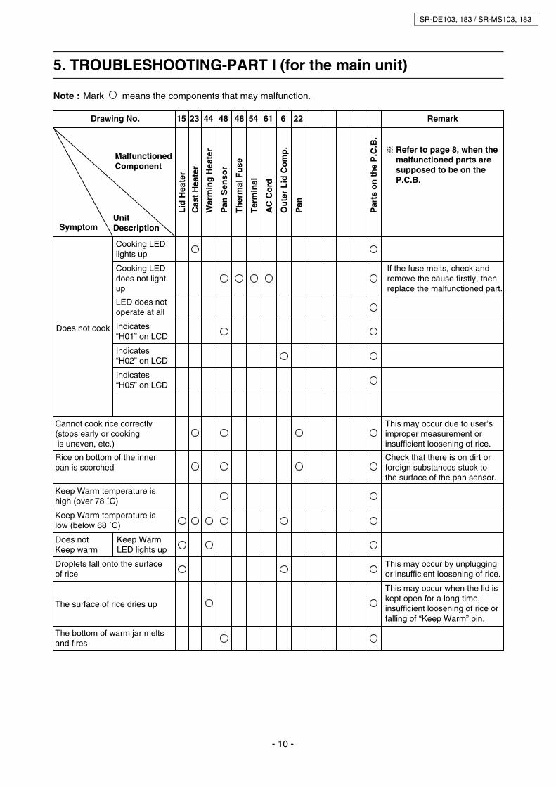
5. TROUBLESHOOTING-PART I (for the main unit)
Note :
Drawing No. Remark
MalfunctionedComponent
15 23 44 48 48 54 61 6 22
Lid
Hea
ter
Cas
t H
eate
r
War
min
g H
eate
r
Pan
Sen
sor
Th
erm
al F
use
Ter
min
al
AC
Co
rd
Ou
ter
Lid
Co
mp
.
Pan
Par
ts o
n t
he
P.C
.B.
Refer to page 8, when themalfunctioned parts aresupposed to be on the P.C.B.
Does not cook
Cooking LEDlights up
UnitDescriptionSymptom
Cannot cook rice correctly(stops early or cooking is uneven, etc.)
This may occur due to user’simproper measurement orinsufficient loosening of rice.
Rice on bottom of the innerpan is scorched
Keep Warm temperature ishigh (over 78 ˚C)
Check that there is on dirt orforeign substances stuck tothe surface of the pan sensor.
This may occur by unpluggingor insufficient loosening of rice.
This may occur when the lid iskept open for a long time, insufficient loosening of rice orfalling of “Keep Warm” pin.
Mark means the components that may malfunction.
SR-DE103, 183 / SR-MS103, 183
LED does notoperate at all
Indicates“H01” on LCD
Indicates“H02” on LCD
Indicates“H05” on LCD
Cooking LEDdoes not lightup
If the fuse melts, check and remove the cause firstly, thenreplace the malfunctioned part.
Keep Warm temperature islow (below 68 ˚C)
Does notKeep warm
Keep WarmLED lights up
Droplets fall onto the surfaceof rice
The surface of rice dries up
The bottom of warm jar meltsand fires

SR-DE103, 183 / SR-MS103, 183
- 11 -
6. QUICK CHECK TEST FOR THE CONTROL BOARD
Check performance of the P.C.B. in the following procedure. If any failure detected, repeat the performanceagain. (Refer to page 8). If still abnormal, replace spare parts on the control panel or the whole control board(comp.) according to “Troubleshooting-Part II” on page 12 and “Problem Diagnosing Table” under subject of“4.2 Self-diagnosing” on page 9.
Connect the unit to a power source by inserting theplug into an outlet. In the stand-by mode, press the[Start], [Menu Select] and [Keep Warm] button simultaneously with fingers.
1.
With the keys pressed, if all areas on the LCD panellight up, as shown at right in Fig. B, the control boardcan be judged to be normal. (Releasing any or all of the three keys will cancel the test condition)
2.
[Fig. A]
[Fig. B]
When releasing the three keys, the [Hour] lights up asshown in right Fig. C and the buzzer sounds, then cookingstarts. When the pan sensor temperature reaches the cooking end level, the heating operation switches to thewarming mode.
Press the [Keep Warm] button. Operate and check whether other function buttons are normal.
If the above 1 to 4 operation proves to be normal, the P.C.B. comp. can be judged as OK.
3.
4.
[Fig. C]
Start
SR-MS103
FUZZY
Off
MenuSelect
KeepWarm Timer hour min Cooking
Timer
Start
SR-MS103
FUZZY
Off
MenuSelect
KeepWarm Timer hour min Cooking
Timer
Start
SR-MS103
FUZZY
Off
MenuSelect
KeepWarm Timer hour min Cooking
Timer

- 12 -
7. TROUBLESHOOTING-PART II (for the P.C.B.)
Note :
Drawing No. Remark
MalfunctionedComponent
38 SW LCD X1 BZ T RL TR1 BAT
P.C
.B. (
com
p.)
Tac
t S
wit
ch
LC
D
Parts on the control panel
Cer
mic
Res
on
ato
r
Bu
zzer
Tra
nsf
orm
er
Rel
ay
Tri
ac
Fla
t C
able
Li B
atte
ry
Does not cook
Cooking LEDlights up
UnitDescriptionSymptom
Cannot cook rice correctly(stops early or cooking is uneven, etc.)
Rice on bottom of the innerpan is scorched
Keep Warm temperature ishigh (over 78 ˚C)
Mark means the components that may malfunction.
SR-DE103, 183 / SR-MS103, 183
LED does notoperate at all
Cooking LEDdoes not lightup
Keep Warm temperature islow (below 68 ˚C)
Does notKeep warm
Keep WarmLED lights up
Does not keep warmcontinuously
Droplets fall onto the surfaceof rice
Buzzer doesnot sound
Part of the LCD is blank
The clock display disappearsafter unplugging
Other operationsare normal

SR-DE103, 183 / SR-MS103, 183
- 13 -
8. TEST METHOD
1. Insert the pan into the cooker main body and turn it slightly clockwise and anti-clockwise to place the pan properly on top of the cast heater.2. Pour small quantity of water into the pan so that the bottom of the pan is immersed with water. Close the lid completely.3. After connecting to power, select [Quick] from [Menu Select] and then press [Start] button.4. When the water boils, the cooker will blow off steam. When you see the steam, open the lid, and then press the brim of the pan to completely touch it to the cast heater. Then check the water bubbling condition.
8.1 Bubble test
After confirming the bubble test is acceptable, spread twoor three sheets of tissue paper (or gauze) over bottom of the pan to leave the cooker on without closing the lid.
Note :
• Be sure to fully open the lid to protect the plastic parts from thermal distortion caused by steam.• Make holes in the tissue paper (or gauze), as shown, so that it will not float up during steaming.
8.2 Steaming test
See the right figures :
8.3 Keep Warm test
• Water bubbles appear at three areas and are distributed evenly around the circle..............Acceptable• Water bubbles are distributed unevenly and not around the circle......................................Unacceptable• The unacceptable result is possibly due to incomplete contact of bottom of pan and the cast heater. So please check the heater surface for foreign material and remove them or replace the defective part (pan or cast heater).
1. Place a mercury thermometer between urethane foam blocks as shown below. Urethane foam blocks (ASN-300) and the thermometer (ASN-150H) are supplied as spare parts.2. Place the urethane foam blocks holding the thermometer into central bottom of the pan and allow the cooker to run in the “Keep Warm” condition for more than 1 hour.3. More than 1 hour later, open the lid and read the temperature within 10 seconds. - If it is within 69˚C - 77˚C, then considered as normal. - If the warming temperature is out of this range, check whether there is any dirt of foreign material stuck on the pan sensor or bottom of the pan, if so, please remove them. - If nothing is found, adjust the warming temperature and replace the control circuit board (comp.)
Inner pan (top view)
Holes oftissue paper
Brim of pan
Bubble
Tissue paper
Mercury thermometer
Urethane foam blocks
Mercury thermometer
Pan

- 14 -
SR-DE103, 183 / SR-MS103, 183
9. REPLACING OF P.C.B. (Comp.)
• Open the lid and place the cooker upside down on a rubber sheet to protect it, as shown in the right figure.
• Unplug the power cord.
• Remove the screw (1) on power socket cover and take out the power socket and its cover (comp.)
• Remove the wiring of power socket (3 places).
1. Remove the power socket (comp.)
Remove the retaining screw of the body
Remove the hinge cover
• Remove the 4 retaining screws of the body.
2.
• Remove the retaining screw first, and then insert the screwdriver between hinge cover and body, as shown in the right figure.
• Pry the screwdriver outward like a lever to disconnect the hinge cover.
3.

SR-DE103, 183 / SR-MS103, 183
- 15 -
• Place the cooker upside down on a rubber sheet, then insert the screwdriver upright for about 30 - 40 mm., as shown in the right figure.
• Turn the screwdriver in arrow direction to remove the body, as shown in the right figure.
• Do not knock at the screwdriver, othewise the parts contacted with screwdriver will be damaged. Please follow the above procedures to remove.
4.
Note :
• For connectors or thing like this, please pull outward directly. If pulled out in different directions, the coil may be damaged or P.C.B. cracks due to the pressure applied on it.
• When pulling out the fastening terminal, please press the pin down in arrow direction while pulling. Otherwise, the terminal can not be pulled out.
Note :
Please wear an anti-static wring strap or take relativemeasures to prevent electric shock.
Remove the body of cooker
Remove the wiring of P.C.B. component
Remove the P.C.B. base (comp.)
• Pull out each connector with a pincers.
• Pull out the fastening terminals (3 places) with a pincers.
5.
• Remove the fire-retardant tape attached on the P.C.B.
• Unplug the wiring connected to P.C.B.
• Remove the retaining screw on P.C.B. base (3 places).
• Take out the P.C.B. base directly with hand.
• Remove another fire-retardant tape attached on the P.C.B.
6.

- 16 -
SR-DE103, 183 / SR-MS103, 183
• Remove the tabs at (a) gently, then take out the P.C.B. (operating side) while lifting.
• Remove another fire-retardant tape attached on the bottom of the P.C.B.
• Remove the retaining screws gently. Then take out the P.C.B. (power side) while lifting.
7. Take out the P.C.B. component
Assembly of P.C.B. base (comp.)
• When assembling the P.C.B. base (comp.), please proceed in reverse to disassembly.
• When reassembling, make sure to attach the fire-retardant tapes as what they are before removing.
8.
Note :

SR-DE103, 183 / SR-MS103, 183
- 17 -
10. REPLACING OF CAST HEATER
• Remove the power socket and body in referring to replacing of P.C.B. base (comp.)
1.
• Remove the retaining screw of cast heater (3 pieces).
• Take out the cast heater from protection frame.
• Please reassemble the cast heater in reverse to disassembly.
Note :• When reassembling, make sure to attach the fire-retardant tapes as what they are before removing.
3.
4.
Remove the power socket (comp.) and body
• Tear off the retaining tapes (2 places) on the wiring of the pan sensor.
• Remove the connections (2 places) between pan sensor and P.C.B.
• Remove the wiring (1 place) connected between pan sensor and cast heater.
• Remove the connection (1 place) between cast heater and P.C.B.
• Remove the grounding wire.
• Remove the connections (3 places) on base of sensor.
• Take out the base of sensor.
2. Remove the base of sensor
Remove the cast heater
Reassembly

- 18 -
SR-DE103, 183 / SR-MS103, 183
11. REPLACING OF PAN SENSOR AND THERMAL FUSE
• Remove the cast heater in referring to replacing of cast heater.
1. Remove the cast heater
Remove the pan sensor
Replacing of thermal fuse
• Upright the tabs (3 places) as shown in the right figure, then take out the pan sensor.
Note :• Do not deform the spring when removing.
2.
• The procedure of replacing of pan sensor is actually a procedure of replacing of thermal fuse A/B, for they both fixed inside of pan sensor.
• Please reassemble the pan sensor in reverse to disassembly.
Note :• Do not deform the spring when assembling.• Do not slant the spring when assembling.• Check the direction of pan sensor.
3.
Reassembly4.

SR-DE103, 183 / SR-MS103, 183
- 19 -
12. PARTS EXPLODED VIEW AND REPLACEMENT PARTS LIST
12.1 Parts Exploded View
19
20
33
3
2
1
4
5
6
7
9
8
11
15
16
14
13
12
10
22
23
24
25
27
3217
18
31
30
28
29
21
XTN4+8GFJ
XTB4+12GFJ
(FOR MS SERIES) (FOR DE SERIES)
XTL4+10RTW
XTL4+16AVW
(FOR MS SERIES) (FOR DE SERIES)
XYM4+E10FNS
XYC4+CF8FJ
XTB4+12GFJ
XTB4+12GFJ
26

- 20 -
SR-DE103, 183 / SR-MS103, 183
12.2 Packing View
(FOR MS SERIES ONLY)
3
1
4
7
6
2
5

SR-DE103, 183 / SR-MS103, 183
- 21 -
12.3 Replacement Parts List : SR-DE103 / SR-DE183
Important safety notice :
Parts List
REF.NO.
PART NAME PART NO. SAFETY
S
S
S
S
S
S
S
DE103 DE183
MODEL
STEAM VENT ASSY1 ARB54T977-0U
Components identified by mark have special characteristics important for safety.When replacing any of these components, use only manufacturer’s specified part.
• •
REMARKTH HK PSV SIN-
RBDUSA/CND
AU/NZ
INDO SIN-DBD
MY TW PAN
COUNTRY / Q’TY
1
OUTER LID ASSY2
LID CAUTION LABEL3
ARB01T977W9U • •ARB01H977W9U • •ARB01V977W9U •ARB01L977W9U
••
ARB01S977W9U •ARB01M977W9U • •ARB01U977W9U • •ARB01A978W9U •ARB01B978W9U
ARB32T975
ARB32H975
ARB32V975
ARB32L977
ARB32A975
ARB32B978
ARB32U975
INNER PAN5 ARE50T9771
•
1
1 1 1 1 1 1 1 1 1 1
1 1 1 1 1
CAST HEATER ASSY6 ARL20T975-0U 1 1
1
1 1 1
1 1 1 1
1
1
1
1 1
1
• •• •
• •
S • •ARL20S975-0U S • •
ARL20U975-0U S • •
ARL20M977-0U S • •
ARL20A975-0U S
S
S
S
S
S
S
S
•
ARE50T978 1 1 1 1••
PAN PACKING HOLDER4 ARH69T977-W9 1 1 1 1 1 1 1 1 1 1
1 1 1
1• •
UPPER FRAME ASSY8 ARE00T977W9U 1 1 1 1 1 1 1 1 1•ARE00A978W9U •
•
HINGE COVER7 ARE40T975-W9 1 1 1 1 1 1 1 1 1 1
1 1
1• •
HANDLE9 ARB10T975-W9 1 1 1 1 1 1 1 1 1 1 1• •
HOOK BUTTON SPRING12 ARE06EA29 1 1 1 1 1 1 1 1 1 1 1• •
LEAD WIRE B ASSY18 ARN98T975-0U 1 1 1 1 1 1 1 1 1 1 1• •
PROTECTING FRAMECOMPLETE
20 ARE20T975
ARE20T976
1 1 1 1 1 1 1 1
1 1
1
1 1 1 1 1 1• •S
S
S
S
S
HINGE EARTH LEAD WIRE21
THERMOSTAT ASSY22
ARE46T962
ARE46H962
ARE46T976
ARE46S976
ARS10T975-0U
1
1
1
1
1
1 1 1 1 1 1 1
1 1 1 1 1 1 1
1 1 1 1
••
••
•SARS10H975-0U •
PCB BASE ASSY19 ARH01T977-0U
ARH01L977-0U
ARH01U977-0U
ARH01A978-0U
ARH01H977-0U
1
1
1 1
1
1 1
1
1 1
1• •• •
••
••
LEAD WIRE A ASSY17 ARN97T975-0U 1 1 1 1 1 1 1 1 1 1 1• •
HOOK BUTTON10 ARE05T977-W9 1 1 1 1 1 1 1 1 1 1 1• •
UPPER FRAME13 ARE00T977-W9
ARE00A978-W9
1 1 1 1 1 1 1 1
1 1
1••
•
DECORATIVE PANEL16 ARN21T977-AV
ARN21U977-AV
ARN21T978-AV
ARN21U978-AV
ARN24U977-NK
1 1 1 1 1 1 1
1 1 1 1
1
1
1 1
1
1••
••
DECORATIVE PANEL B15 ARN24T977-NK 1 1 1 1 1 1 1
1
1 1
1
• •• •
ARN24Z977-NK • •
•
•
•
•
1
1
1 1
1
1 1
1
1
1
1
1
1 1
1
1
1
1
1
1
1
ENGLISH / THAI
ENGLISH
ENGLISH / VIETNAM
INDONESIAN
ENGLISH / FRENCH
ENGLISH / SPAIN
CHINESE
CHANGE WATER LEVEL

- 22 -
SR-DE103, 183 / SR-MS103, 183
Parts List
REF.NO.
PART NAME PART NO. SAFETY
S
S
S
S
S
S
S
S
S
S
S
S
S
S
S
S
S
S
S
S
DE103 DE183
MODEL
ARS10H976-0U
ARS10U976-0U
ARS10A976-0U
AQS61T2701
•
REMARKTH HK PSV SIN-
RBDUSA/CND
AU/NZ
INDO SIN-DBD
MY TW PAN
COUNTRY / Q’TY
1
1
OUTER SPRING23
ARY30T977-W9
ARY30H977-W9
ARY30V9771W9
ARY30Y977-W9
ARY30L977-W9
ARY30S977-W9
ARY30M9771W9
ARY30U977-W9
ARY30Z977-W9
ARY30T978-W9
ARY30H978-W9
ARY30S978-W9
ARY30M9781W9
ARY30U978-W9
ARY30A9781W9
ARY30B9781W9
ARY30Z978-W9
ARE10T975-W9
ARE10T976-W9
NAME PLATE24
••• •
••••••
1
1 1 1 1 1 1 1
1
1 1
1 1
1
1
1
1
1
1
1
1
1
1
1
1 1 1
BODY25
ARH90E7221FOOT RUBBER26
ARG10T92010U
ARF19T93410U
INLET27
••
•
•
• •
•ARE10A976-W9 •
•
S
S
S
S
S
S
S
S
S
S
•
•
1
1
1
1
1
1
1 1
1 1
1 1 1 1 1 1
1 1 CHANGE MATERIAL TO PP NH601
1
1 1 1 1
••
1 1 1 1 1 1 1 1 1
1 1 1 1 1 1 1 1
•ARK53T975-W9
ARF27T975-W9
•••
1ARK53ED37WQU • •
1 1
1 1
1 1
1 1 1 1 1 1 1 1 1
2 2 2 2 2 2 2 2 2 2 2
••
MEASURING CUP30
INLET PLATE28
STEAMING BASKET
STEAMING BASKET ASSY
29
ASR792-454BK 1 1 1 1 1 1 1 1 1 1 1• •
POWER CORD ASSY (C-3)32 ARQ00T959-0U
SPOWER CORD ASSY (SH-3) ARQ00T920-0U
SPOWER CORD ASSY (S-3) ARQ00M96110U
SPOWER CORD ASSY (S-3) ARQ00S975-0U
SPOWER CORD ASSY (A-3) AQQ00U526-0U
SPOWER CORD ASSY (A-2P) ARQ00A97510U
SPOWER CORD ASSY (A-3) ARQ00Z975-0U
1• •
1 1
1 1 1••
••
SIDE HEATER ASSY33 1 1 1
1
1
••
RICE SCOOP31 ARK02T975-W9 1 1 1 1 1 1 1 1 1 1 1• •
1 1 1
••
ARL10T975-0U
ARL10S975-0U
ARL10U975-0U
ARL10T976-0U
ARL10S976-0U
ARL10U976-0U
ARL10A976-0U
1 1
1 1
1 1
1 1
1
1• ••
1
1 1
1
• ••
••
•
••
•
•
1•SARS10T976-0U
1SARS10U975-0U •

- 23 -
SR-DE103, 183 / SR-MS103, 183
Screws
REF.NO.
PART NAME PART NO. SAFETYDE103 DE183
MODEL
XTB4+12GFJ
XTB4+12GFJ
XTB4+12GFJ
XYC4+CF8FJ
XTN4+16AVW
XYN4+C10FNS
XYN4+C7FNS
•
REMARKTH HK PSV SIN-
RBDUSA/CND
AU/NZ
INDO SIN-DBD
MY TW PAN
COUNTRY / Q’TY
1
TAPPING SCREW
TAPPING SCREW
SEMS TAPPING SCREW
SEMS TAPPING SCREW
SEMS SCREW
TAPPING SCREW
TAPPING SCREW
••••••
••••
•••
1 1 1 1 1 1 1 1 1 1
1 1 1 1 1 1 1 1 1 1 1
1 1 1 1 1 1 1 1 1 1 1
2 2 2 2 2 2 2 2 2 2 2
1 1 1 1 1 1 1 1 1 1 1
4 4 4 4 4 4 4 4 4 4 4
3 3 3 3 3 3 3 3 3 3 3
FIX BODY
FIX PCB BASE ASSY
FIX EARTH CONNECTION
FIX HINGE COVER
FIX INLET PLATE
FIX CAST HEATER ASSY
FIX INTERNAL WIRING
Packing List
REF.NO.
PART NAME PART NO. SAFETY
S
S
S
S
S
S
S
S
S
S
S
S
DE103 DE183
MODEL
ARZ19T977
ARZ19H977
ARZ19V977
ARZ19L9771
ARZ19S977
ARZ19M977
ARZ19U977
ARZ19A978-A
ARZ19A978-B
ARZ19Z9771
ARZ04T975-0U
•
REMARKTH HK PSV SIN-
RBDUSA/CND
AU/NZ
INDO SIN-DBD
MY TW PAN
COUNTRY / Q’TY
OPERATION INSTRUCTION
OPERATION INSTRUCTION A
OPERATION INSTRUCTION B
OPERATION INSTRUCTION
UPPER PAD ASSY
1
2
ASR762T929-KPOLYETHYLENE SHEET3
ASR758T344BRUST PROOF PAPER4
ARZ11T975-0ULOW PAD ASSY5
ARZ01T977-W9
ARZ01H977-W9
ARZ01V977-W9
ARZ01Y977-W9
ARZ01L977-W9
ARZ01S977-W9
ARZ01M977-W9
ARZ01U977-W9
ARZ01Z977-W9
ARZ01T978-W9
ARZ01H978-W9
ARZ01S978-W9
ARZ01M978-W9
ARZ01U978-W9
ARZ01A978-W9
ARZ01B978-W9
ARZ01Z978-W9
INNER PACKING CASE6
•
••••••
••••
•••
• •• •• ••
••••••••
•
•
••••••••
•
1
1
1
1
1 1
1 1
1
1 1 1 1 1 1 1 1 1 1 1
1 1 1 1 1 1 1 1 1 1 1
1 1 1 1 1 1 1 1 1 1 1
1 1 1 1 1 1 1 1 1 1 1
1
1
1
1
1
1
1
1
1
1
1
1
1
1
1
1
1
1
1
1 1
ENGLISH / THAI
ENGLISH / CHINESE
ENGLISH / VIETNAMESE
INDONESIAN
ENGLISH / CHINESE
ENGLISH / CHINESE/ MALAYSIA
CHINESE
ENGLISH / FRENCH / CHINESE
KOREAN / SPANISH
ENGLISH / CHINESE

SR-DE103, 183 / SR-MS103, 183
- 24 -
12.4 Replacement Parts List : SR-MS103 / SR-MS183Parts List
REF.NO.
PART NAME PART NO. SAFETY
S
S
S
S
S
S
S
S
S
S
REMARKMS103 MS183 TH HK PSV SIN-
RBDSIN-DBD
TW USA/CND
AU/NZ
MODEL COUNTRY / Q’TY
STEAM VENT ASSY1 ARC00T975W9U
OUTER LID ASSY2
LID CAUTION LABEL3
INNER LID ASSY4
INNER PAN COMPLETE5
ARB01T975W9U
ARB01H975W9U
ARB01V975W9U
ARB01S975W9U
ARB01U975W9U
ARB01A975W9U
ARB01Z975W9U
ARB32T975
ARB32H975
ARB32V975
ARB32U975
ARB32A975
ARC80T975-0U
ARE50T97510U
CAST HEATER ASSY6 ARL20T975-0U
ARL20S975-0U
ARL20U975-0U
ARL20A975-0U
ARL20M977-0U
ARE50T976-0U
ENGLISH / THAI
ENGLISH
ENGLISH / VIETNAM
CHINESE
CHANGE WATER LEVEL
ENGLISH / FRENCH
1
1
1
1
1 1 1 1 1 1
1 1 1 1 1 1 1 1
1 1 1 1 1
1
1
1 1 1 1 1 1
1 1
1
1 1 1 1 1 1 1 1
1 1 1 1 1 1
1
1
1 1 1 1 1 1 1 1
1 1 1 1 1 1 1 1
1 1 1 1 1 1 1 1
1 1 1 1 1 1 1 1
1 1 1 1 1 1 1
1 1 1 1 1 1 1
1
1
1 1 1 1 1
1
1
1
1 1 1 1 1
1
1 1
1 1 1 1 1
1
1 1
1 1 1 1 1 1 1 1
1 1 1 1
1
1
1
1
1 1
1
1
1 1
1
1
1
1
1
1
1
1
1 1 1 1 1 1 1 1
• •• •• •• •• •• •• •• •• •• •• •• •• •• •
••• •
HINGE COVER7 ARE40T975-W9 • •UPPER FRAME ASSY8 ARE00T975W9U
ARE00A975W9U
• •• •
HANDLE9 ARB10T975-W9 • •HOOK BUTTON10 ARE08T975-W9 • •HOOK BUTTON SHAFT11 ARE05T975-W9 • •HOOK BUTTON SPRING12 ARE09ED37 • •UPPER FRAME13 ARE00T975-W9
ARE00A975-W9
• •• •
• •
ESCUTCHEON SEAL14 ARN34T975 • •DECORATIVE PANEL B15 ARN24T975-OG
ARN24U975-OG
••
ESCUTCHEON16 ARN11T975-AV
LEAD WIRE A ASSY17 ARN97T975-0U
ARN11U975-AV
ARN11T976-AV
ARN11U976-AV
•
••
•ARN24Z975-OG • •
• •• •• •• •
S • •
1
1
1 1 1
1
1
1PCB BASE ASSY19 ARH01T97510U
PROTECTING FRAMECOMPLETE
20 ARE20T975
ARE20T976
HINGE EARTH LEAD WIRE21
THERMOSTAT ASSY22
OUTER SPRING23
ARE46T962
ARE46H962
ARE46T976
ARE46S976
ARS10T975-0U
ARS10H975-0U
ARS10U975-0U
ARS10A975-0U
ARS10T976-0U
ARS10H976-0U
ARS10U976-0U
ARS10A976-0U
AQS61T2701
S • •ARH01H975-0U S • •ARH01U975-0U S • •ARH01A975-0U S
S
S
S
S
S
S
S
S
S
S
S
S
•
•
•
•••••
•
•
•••
••••
•
1 1 1 1 1 1 1 1
1 1 1 1 1 1 1 1
1 1 1 1 1 1 1 1
1
1 1 1 1 1 1
1
1 1 1 1 1
1
1
1
1
1
1
1
1
1 1 1 1
1 1 1 1
1
LEAD WIRE B ASSY18 ARN98T975-0U S • •

- 25 -
SR-DE103, 183 / SR-MS103, 183
Parts List
REF.NO.
PART NAME PART NO. SAFETY
S
S
S
S
S
S
S
S
S
S
S
S
S
S
S
S
S
REMARKMS103 MS183 TH HK PSV SIN-
RBDSIN-DBD
TW USA/CND
AU/NZ
MODEL COUNTRY / Q’TY
ARY30V9751W9
ARY30Y975-W9
ARY30S975-W9
ARY30U975-W9
ARY30A9751W9
ARY30Z975-W9
ARY30T976-W9
ARY30H976-W9
ARY30V9761W9
ARY30Y976-W9
ARY30S976-W9
ARY30U976-W9
ARY30A9761W9
ARY30Z976-W9
BODY25 ARE10T975-W9
FOOT RUBBER26 ARH90E7221
INLET27 ARG10T92010U
INLET PLATE28 ARF27T975-W9
STEAMING BASKET
STEAMING BASKET ASSY
29 ARK53T975-W9
MEASURING CUP30 ASR792-454BK
RICE SCOOP31 ARK02T975-W9
POWER CORD ASSY (C-3)32 ARQ00T959-0U
SIDE HEATER ASSY33 ARL10T975-0U
ARL10S975-0U
ARL10U975-0U
ARL10A975-0U
ARL10T976-0U
ARL10S976-0U
ARL10U976-0U
ARL10A976-0U
POWER CORD ASSY (SH-3) ARQ00T920-0U
POWER CORD ASSY (S-3) ARQ00M96110U
POWER CORD ASSY (S-3) ARQ00S975-0U
POWER CORD ASSY (A-3) AQQ00U526-0U
POWER CORD ASSY (A-2P) ARQ00A97510U
POWER CORD ASSY (A-3) ARQ00Z975-0U
ARF19T93410U
ARE10T976-W9
1
1
1 1 1 1 1 1
1
1
1 1 1 1 1 1
1
1
1 1 1 1 1 1 1
1
1
1 1 1 1 1 1
1
1
1 1 1 1 1 1 1 1
1 1 1 1 1 1 1
1 1 1 1 1 1 1
1
1 1
1
1
1
1
1 1 1 1
1
1
1
1
1
1 1 1 1
1
1
1
1
2 2 2 2 2 2 2 2
1
1
1
1
1
1
1
1
1
1
1
1
••
S
S
••
••••
••••••••
•ARE10A975-W9 CHANGE MATERIAL TO PP NH601
CHANGE MATERIAL TO PP NH601
••
ARE10A976-W9 •• •
• •• •• •• •• •• •• •• •• •
••
•
••
•
•
• •• •• •• •
ARK53ED37WQU 1• •
S •
S
S
S
S
S
S
S
S
S
S
S
S
S
1ARY30H975-W9
1NAME PLATE24 ARY30T975-W9

- 26 -
SR-DE103, 183 / SR-MS103, 183
Screws
REF.NO.
PART NAME PART NO. SAFETY REMARKMS103 MS183 TH HK PSV SIN-
RBDSIN-DBD
TW USA/CND
AU/NZ
MODEL COUNTRY / Q’TY
TAPPING SCREW
XTB4+12GFJ
XTB4+12GFJ
TAPPING SCREW
XYC4+CF8FJSEMS TAPPING SCREW
XTN4+16AVWTAPPING SCREW
XTB4+12GFJTAPPING SCREW
XYN4+C10FNSSEMS TAPPING SCREW
XYN4+C7FNSSEMS SCREW
1
2
FIX BODY
FIX PCB BASE ASSY
FIX EARTH CONNECTION
FIX HINGE COVER
FIX INLET PLATE
FIX CAST HEATER ASSY
FIX INTERNAL WIRING
4 44 4 4 4 4 4
3 33 3 3 3 3 3
1 11 1 1 1 1
1 11 1 1 1 1 1
1 11 1 1 1 1 1
1 11 1 1 1 1 1
2 22 2 2 2 2 2
•••••••
•••••••
Packing List
REF.NO.
PART NAME PART NO. SAFETY
S
S
S
S
S
S
S
REMARKMS103 MS183 TH HK PSV SIN-
RBDSIN-DBD
TW USA/CND
AU/NZ
MODEL COUNTRY / Q’TY
OPERATION INSTRUCTION
ARZ19H975
ARZ19T975
ARZ19V975
ARZ19S975
ARZ19U9751
ARZ19A975-AOPERATION INSTRUCTION A
OPERATION INSTRUCTION B
OPERATION INSTRUCTION
ARZ19A975-B
ARZ19Z9751
UPPER PAD ASSY ARZ04T975-0U
3 POLYETHYLENE SHEET ASR762T929-K
4 RUST PROOF PAPER ASR758T344B
5 LOW PAD ASSY
6 INNER PACKING CASE
7 MENU BOOK
ARZ11T975-0U
ARZ01T975-W9
ARZ01H975-W9
ARZ01V975-W9
ARZ01Y975-W9
ARZ01S975-W9
ARZ01U975-W9
ARZ01A975-W9
ARZ01Z975-W9
ARZ01T976-W9
ARZ01H976-W9
ARZ01V976-W9
ARZ01Y976-W9
ARZ01S976-W9
ARZ01U976-W9
ARZ01A976-W9
ARZ01Z976-W9
ARZ20T9751
ARZ20S9752
ARZ20A975
ENGLISH / THAI
ENGLISH / CHINESE
ENGLISH / VIETNAMESE
ENGLISH / CHINESE
ENGLISH / CHINESE
CHINESE
ENGLISH / FRENCH / CHINESE
KOREAN / SPANISH
THAI / ENGLISH / VIETNAMESE
ENGLISH / CHINESE (HK) / CHINESE (TW)
FRENCH / KOREAN / SPANISH
ENGLISH / CHINESE
1 1
1
1
1
1
1
1
1
1 11 1 1 1 1 1
1 11 1 1 1 1 1
1 11 1 1 1 1 1
1 11 1 1 1 1 1
1 11
1 1 1
1
1
1
1
1
1
1
1
1
1
1
1
1
1
1
1
1
1
1
•••••••
•••••••
S
S
S
•••••••••••••••••
••
•
•••
•
•••
••ARZ20Z975 ••
•
••

SR-DE103, 183 / SR-MS103, 183
- 27 -
DETAIL CHANGE NOTICE
REVISION ITEM NO. PAGE DETAIL REMARK
MAR. 2011
JUN. 2011
1 1 REVISE ADD. REVISION AND DESTINATION
ADD. COUNTRIES FOR SALES AS TW, USA/CND, PANAMA AND AU/NZ
2 4 REVISE SPEC. ADD. DATA OF NEW COUNTRIES
3 19 CUTTING INLET CASE BUT ADD.FOOT RUBBER IN EXPLODE VIEWNO. 26
REVISE PARTS TO USE ASSEMBLY
4 21 - 26 ADD. COUNTRIES & PART LIST ADD. COUNTRIES AND PART LIST FOR TW, USA/CND, PANAMA AND AU/NZ
5 22, 25 ADD. PART NO. OF STEAMING BASKET
REVISE FOR HONG KONG MODEL ONLY
6 26 REVISE PART NO. OF OPERATIONINSTRUCTION
PRODUCT NAME IS WRONG
1 21 - 23 REV. REF. NO. 2, 5, 13, 22, 24, 29AND PACKING LIST
REV. NEW PART NO. FOR MODELSR-DE103, 183
JUL. 2011 1 21, 24 ADD PART NO. OF REF. NO. 15 FOR MODEL AUS-NZ ONLY
2 23, 26 REVISE PART NO. OF OPERATION INS. FOR MODEL AUS-NZ
3 26 ADD PART NO. OF MENU BOOK FOR MODEL AUS-NZ
2 24 - 26 REV. REF. NO. 5, 13, 19, 29 ANDPACKING LIST
REV. NEW PART NO. FOR MODELSR-MS103, 183