Embed Size (px)
Citation preview

Orange Pi PC User Manual Shenzhen Xunlong Software CO., Limited
www.orangepi.org www.xunlong.tv
Orange Pi PC
User Manual < V0.9.1 >
�
�
�
�
�
�
�
�
�
�
�

Orange Pi PC User Manual Shenzhen Xunlong Software CO., Limited
www.orangepi.org www.xunlong.tv
What’s Orange Pi PC?
It’s an open-source single-board computer. It can run Android 4.4, Ubuntu, Debian, Rasberry Pi
Image, as well as the Banana Pi Image. It uses the AllWinner H3 SoC, and has 1GB DDR3 SDRAM.
What can I do with Orange Pi PC? Build…
A computer
A wireless server
Games
Music and sounds
HD video
A speaker
Android
Scratch
Have much more functions, because Orange Pi PC is open source.
Whom is it for?
Orange Pi PC is for anyone who wants to create with technology
– not just consuming. It's a simple, fun, useful tool and you can use it to take control of the world
around you.
Orange Pi PC User Manual Shenzhen Xunlong Software CO., Limited
www.orangepi.org www.xunlong.tv
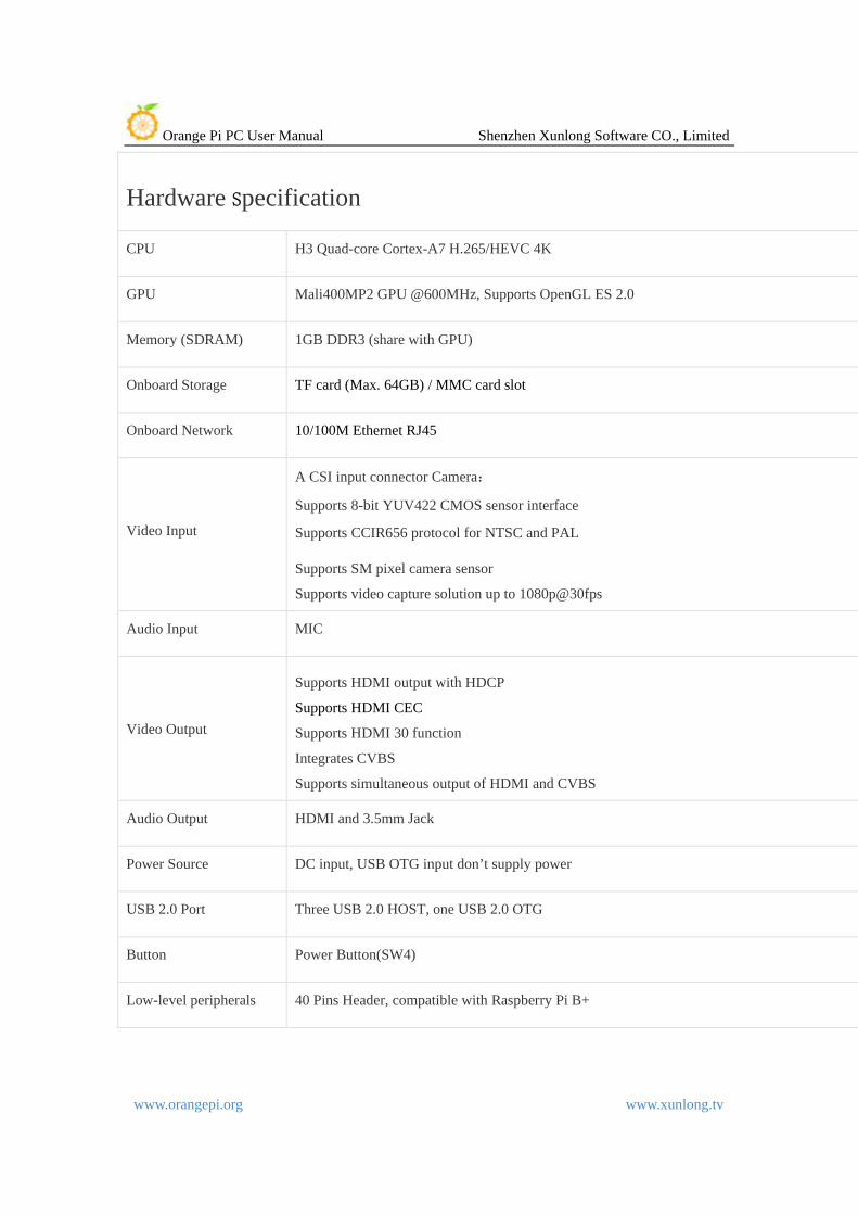
Hardware Specification
CPU H3 Quad-core Cortex-A7 H.265/HEVC 4K
GPU Mali400MP2 GPU @600MHz, Supports OpenGL ES 2.0
Memory (SDRAM) 1GB DDR3 (share with GPU)
Onboard Storage TF card (Max. 64GB) / MMC card slot
Onboard Network 10/100M Ethernet RJ45
Video Input
A CSI input connector Camera:
Supports 8-bit YUV422 CMOS sensor interface
Supports CCIR656 protocol for NTSC and PAL
Supports SM pixel camera sensor
Supports video capture solution up to 1080p@30fps
Audio Input MIC
Video Output
Supports HDMI output with HDCP
Supports HDMI CEC
Supports HDMI 30 function
Integrates CVBS
Supports simultaneous output of HDMI and CVBS
Audio Output HDMI and 3.5mm Jack
Power Source DC input, USB OTG input don’t supply power
USB 2.0 Port Three USB 2.0 HOST, one USB 2.0 OTG
Button Power Button(SW4)
Low-level peripherals 40 Pins Header, compatible with Raspberry Pi B+

Orange Pi PC User Manual Shenzhen Xunlong Software CO., Limited
www.orangepi.org www.xunlong.tv
GPIO(1x3) pin UART, ground.
LED Power led & Status led
Key IR, POWER
Supported OS Android, Ubuntu, Debian, Rasberry Pi Image
Cosmetic Specification
Product size 85mm × 55mm
Weight 38g
Orange Pi™ is a trademark of the Shenzhen Xunlong Software CO., Limited
Hardware Top view
Bottom view

Orange Pi PC User Manual Shenzhen Xunlong Software CO., Limited
www.orangepi.org www.xunlong.tv
Interface instructions

Orange Pi PC User Manual Shenzhen Xunlong Software CO., Limited
www.orangepi.org www.xunlong.tv
Using method You can use your Orange Pi PC quickly if you follow the following steps, it takes only three steps to boot your Orange Pi PC. Step 1 Necessary Accessories

Orange Pi PC User Manual Shenzhen Xunlong Software CO., Limited
www.orangepi.org www.xunlong.tv
Following accessories are required if it is the first time you use Orange Pi PC.
No. Items Requirements and Instructions
1 TF card • 4Gb min.; class 4 (the class indicates how fast the card is). • Branded TF cards which are much more reliable are the good choice.
2a HDMI to HDMI cable or HDMI to DVI cable
• HDMI to HDMI cable is used to connect HD TV or HD monitor; • HDMI to DVI cable is used to connect DVI monitor.
2b AV video cable A standard AV video cable can be used to connect stimulated monitor if a HDMI monitor is unavailable.
3 Keyboard and mouse
Any keyboard and mouse with USB port is applicable; Keyboard and mouse are high-power, so a USB concentrator is required.
4 Ethernet cable/USB
WiFi(Optional)
Network is optional, It makes more convenient to mount
and upgrade software in your Orange Pi PC.
5 DC power adapter
5V,2V min. high qualified power adaptor,
OTG can not used a power supply.
6 Audio cable (Optional)
• You can select an audio cable with 3.5mm jack to feel stereo audio.

Orange Pi PC User Manual Shenzhen Xunlong Software CO., Limited
www.orangepi.org www.xunlong.tv
HDMI to HDMI cable HDMI to DVI cable AV video cable
TF card DC power adapter
Step 2 Prepare TF card for Orange Pi PC Operation System (OS) should be installed in a TF card before using an Orange Pi PC. In the following we will tell you how to program an OS image file into a TF card Under Windows and Linux OS. How to Program an OS into a TF card? Windows:
1. Insert your TF card into your computer. The capacity of a TF card should be larger than OS image, generally 4GB min. 2. Format the TF card.
i. Download a format tool of TF card, such as TF Formatter. You can download it from the following link, https://www.sdcard.org/downloads/formatter_4/eula_windows/.
ii. Unzip the downloaded file and run the setup.exe to install the tool on your machine.
iii. In the "Options" menu, set "FORMAT TYPE" option to "QUICK”, and “FORMAT SIZE ADJUSTMENT" option should be "ON".

Orange Pi PC User Manual Shenzhen Xunlong Software CO., Limited
www.orangepi.org www.xunlong.tv
iv. Make sure the inserted TF card codes are in accordance with the chosen codes.
v. Click the “Format” button.
3. Download the OS image from the website, the Website is http://www.orangepi.org/downloadresour the ces/
4. Unzip the downloaded file to get the OS image (except android os
image).
5. Program the image file into the TF card.
i. Download a tool,such as Win32 Diskimager, the website is
http://sourceforge.net/projects/win32diskimager/files/Archive/
ii. Open the unzipped image file.
iii. Click “Write” button. Please wait a moment until the image is written.
IV. Click “Exit” button after image is written.
Linux: 1. Insert your TF card into your computer. The capacity of TF should be
larger than the OS image, generally 4GB min..

Orange Pi PC User Manual Shenzhen Xunlong Software CO., Limited
www.orangepi.org www.xunlong.tv
2. Format the TF card. i. Run fdisk –l /dev/sdx command to confirm the TF card code. ii. Run umount /dev/sdxx to un-mount all the partitions of the TF card. iii. Run sudo fdisk /dev/sdx command to configure TF card. Use o command to delete all partitions of TF card and use n command to add a new partition. Then use w command to save and exit. iv. Run sudo mkfs.vfat /dev/sdx1 command to format the new generated partition of TF card as FAT32. (x should be replaced according to your TF card code) You can also skip this step under Linux, because dd command under Linux will format TF card automatically.
3. Download the OS image from the Website http://www.orangepi.org/downloadresources/
4. Unzip the downloaded file (except android os image).
5. Write the image file into the TF card. i. Run fdisk –l /dev/sdx command to confirm the TF card code. ii. Please make sure the hash key of image file is in accordance with the downloaded one (optional). sha1sum [path]/[imagename] A series of numbers will be output and it is the same as the “SHA-1” on the downloaded image page.
iii. Run umount /dev/sdxx to un-mount all the partitions of the TF card.
iv. Run sudo dd bs=4M if=[path]/[imagename] of=/dev/sdx command to write image file to TF card. Please wait a moment until the image written. If 4M is not applicable, please use 1M instead, although it will take much more time.You can use sudo pkill –USR1 –n –x dd command to check progress.
How to write an Android OS image into your TF card?
It is impossible for Android image file to be written into TF card by using dd command under Linux or by using Win32 Diskimager under Windows. PhoenixCard is applicable. (Note : If your laptop card slot cannot burn the TF card, you can use the TF card reader. )
1. Download the Android OS image and PhoenixCard. Download PhoenixCard from https://drive.google.com/file/d/0B_VynIqhAcB7NTg2UkRDdHRWX2s/edit?usp=sharing

Orange Pi PC User Manual Shenzhen Xunlong Software CO., Limited
www.orangepi.org www.xunlong.tv
Download Android OS image from http://www.orangepi.org/downloadresources/
2. Format the TF card
3. Please make sure the inserted TF card is in accordance with the chosen, click “restore” button for TF card format.

Orange Pi PC User Manual Shenzhen Xunlong Software CO., Limited
www.orangepi.org www.xunlong.tv
Successfully to format the TF card to normal, click the “OK” button.
4. Then burn the Android OS image to your TF card. Please pay attention to the following with red marks.

Orange Pi PC User Manual Shenzhen Xunlong Software CO., Limited
www.orangepi.org www.xunlong.tv
Click the “Burn” button.
Burn Android OS image to TF card successfully. Click “Exit”.
Orange Pi PC User Manual Shenzhen Xunlong Software CO., Limited
www.orangepi.org www.xunlong.tv
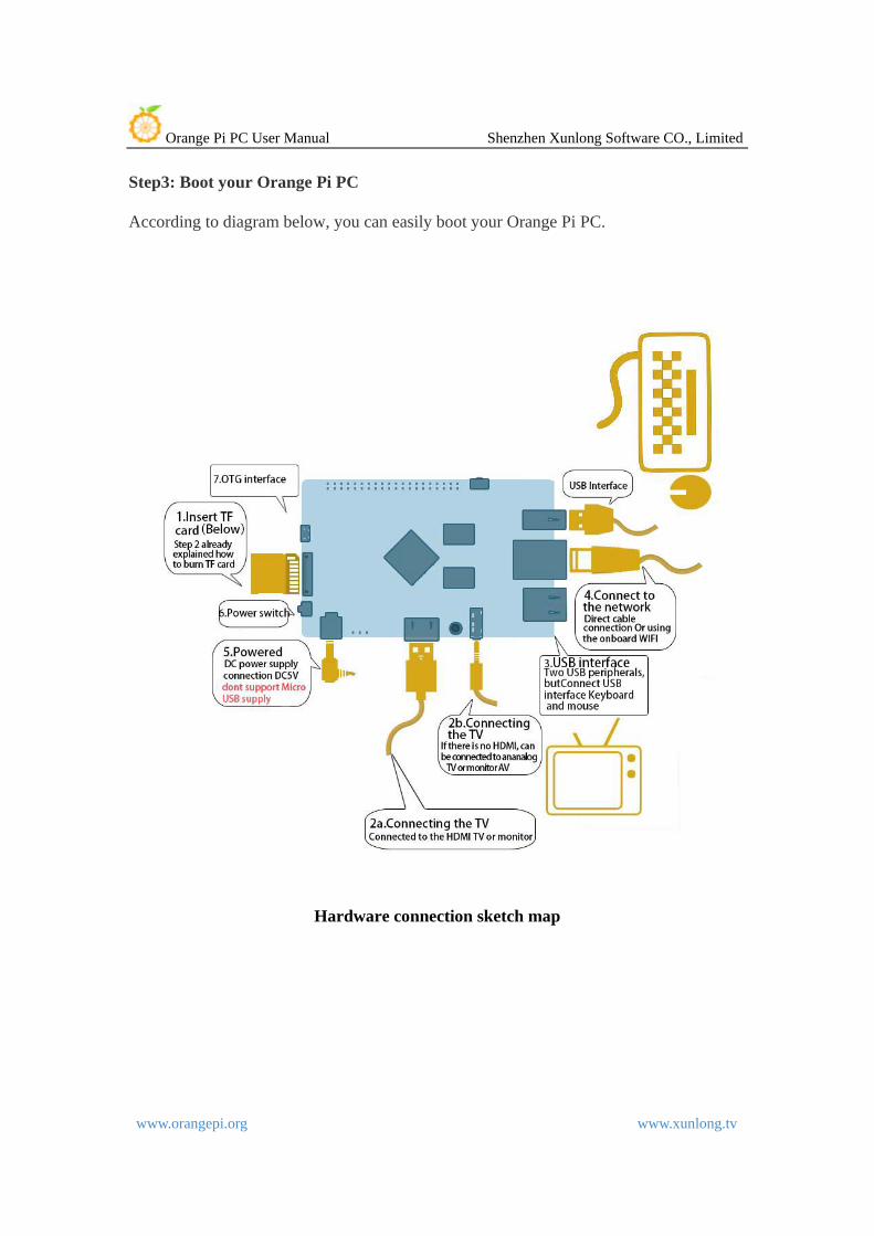
Step3: Boot your Orange Pi PC
According to diagram below, you can easily boot your Orange Pi PC.
Hardware connection sketch map

Orange Pi PC User Manual Shenzhen Xunlong Software CO., Limited
www.orangepi.org www.xunlong.tv
Hardware real objects picture-top view

Orange Pi PC User Manual Shenzhen Xunlong Software CO., Limited
www.orangepi.org www.xunlong.tv
Hardware real objects picture-bottom view
1. Insert the TF card with written-image into the TF card slot on the left edge of the board.
2. In the middle of lower edge of the board is the HDMI Type A (Full sized) port which is used to your Orange Pi PC, HDMI TV or monitor.
If you don’t have a monitor with HDMI or DVI port, you can output audio and video to stimulated TV or monitor with the help of Yellow AV port in the middle of the upper part of the board and audio port on the right side of the board
3. Plug the USB port of the keyboard and mouse into the USB port on the right edge of the board.
4. Ethernet connector is in the middle of the three USB ports, you can link your Orange Pi PC with cable network

Orange Pi PC User Manual Shenzhen Xunlong Software CO., Limited
www.orangepi.org www.xunlong.tv
5. On the right side of the Lower part of the board is the power input port, 5V 2A min. power adapter is applicable. Please do not use low-powered GSM cellphone charger, even though it is marked”5V 2A”.
Note : Micro USB OTG cannot be used as a power supply, which will freeze the board. Only a DC power port can be used to supply power.
If everything in the above-mentioned steps goes very well, the Orange PC will booted in a few minutes. The screen will display the OS GUI(Graphical User Interface). The first boot of a new OS will take a long time. So be patient! Subsequent boots will be much quicker.
Step 4 Turn off your Orange Pi PC You can turn off your Orange Pi PC safely with the help of “OFF” button on the screen. Also you can input command sudo halt or sudo shutdown –h. in the shell to turn off the system. In this case, your Orange Pi PC will be turned off safely, I you just turn off the power supply, it will damage the system of TF card. You’d better press the Power button for 5 seconds at least to cut off the power. . If everything goes very well, you can use orange pi pc now. GPIO specification Orange Pi PC 40-pin GPIO A 40-pin GPIO interface on the Orange Pi PC is the same as Model A and Model B of Raspberry Pi. The picture below is GPIO pin define of Orange Pi PC.
Orange_Pi-PC(H3)
CON3-P01 VCC-3V3 CON3-P02 VCC-5V CON3-P03 TWI0-SDA PA12

Orange Pi PC User Manual Shenzhen Xunlong Software CO., Limited
www.orangepi.org www.xunlong.tv
CON3-P04 VCC-5V CON3-P05 TWI0-SCK PA11 CON3-P06 GND CON3-P07 PWM1 PA6 CON3-P08 UART3_TX PA13 CON3-P09 GND CON3-P10 UART3_RX PA14 CON3-P11 UART2_RX PA1 CON3-P12 PD14 PD14 CON3-P13 UART2_TX PA2 CON3-P14 GND CON3-P15 UART2_CTS PA3 CON3-P16 PC4 PC4 CON3-P17 VCC-3V3 CON3-P18 CAN_RX PC7 CON3-P19 SPI0_MOSI PC0 CON3-P20 GND CON3-P21 SPI0_MISO PC1 CON3-P22 UART2_RTS PA2 CON3-P23 SPI0_CLK PC2 CON3-P24 SPI0_CS0 PC3 CON3-P25 GND CON3-P26 PA21 PA21 CON3-P27 TWI1-SDA PA19 CON3-P28 TWI1-SCK PA18 CON3-P29 PA7 PA7 CON3-P30 GND CON3-P31 PA8 PA8 CON3-P32 UART1_RTS PG8 CON3-P33 PA9 PA9 CON3-P34 GND CON3-P35 PA10 PA10 CON3-P36 UART1_CTS PG9 CON3-P37 PA20 PA20 CON3-P38 UART1_TX PG6 CON3-P39 GND CON3-P40 UART1_RX PG7
Specification of CSI Camera Connector CSI Camera Connector The CSI Camera Connector is a 24-pin FPC connector which can connect external camera module with proper signal pin mappings. The pin of CIS connector can be defined as follows. The connector marked with “CON 1” on the Orange Pi PC is camera connector.

Orange Pi PC User Manual Shenzhen Xunlong Software CO., Limited
www.orangepi.org www.xunlong.tv
OrangePi PC-CSI CON1-P01 NC CON1-P02 GND CON1-P03 TWI2-SDA PE13 CON1-P04 VCC-CSI CON1-P05 TWI2-SCK PE12 CON1-P06 CSI-RESET# PE15 CON1-P07 CSI-VSYNC PE3 CON1-P08 CSI-STBY-EN PE15 CON1-P09 CSI-HSYNC PE2 CON1-P10 VDD1V8-CSI CON1-P11 VCC-CSI CON1-P12 CSI-D7 PE11 CON1-P13 CSI-MCLK PE1 CON1-P14 CSI-D6 PE10 CON1-P15 GND CON1-P16 CSI-D5 PE9 CON1-P17 CSI-PCLK PE0 CON1-P18 CSI-D4 PE8 CON1-P19 CSI-D0 PE4 CON1-P20 CSI-D3 PE7 CON1-P21 CSI-D1 PE5 CON1-P22 CSI-D2 PE6 CON1-P23 GND CON1-P24 AFVCC-CSI