Embed Size (px)
Citation preview

Oracle® Fusion MiddlewareHigh Availability Guide for Oracle Identity and Access Management
11g Release 2 (11.1.2.3)
E56759-02
June 2015
Documentation for administrators, developers, and others that describes high availability concepts as well as administration and configuration procedures to deploy and manage Oracle Fusion Middleware with high availability requirements.

Oracle Fusion Middleware High Availability Guide for Oracle Identity and Access Management 11g Release 2 (11.1.2.3)
E56759-02
Copyright © 2015, Oracle and/or its affiliates. All rights reserved.
Primary Author: Christine Ford
Contributing Author: Fermin Castro, Michael Blevins, Pradeep Bhat, Michael Rhys, Samrat Ray, Jeni Ferns, Richard Delval, Bharath K. Reddy, Susan Kornberg, Joe Paul, Ajay Keni, Amit Sharma, Vasuki Ashok, Olaf Stullich, Jingjing Wei, Olfat Aly, Eileen He, Ramaprakash Sathyanarayan, Apurv Chandra, Atika Jain, Buddhika Kottahachchi, Arun Theebaprakasam, Rajiv Jaisankar, Vinay Kalra, Daniel Shih, Pratima Gogineni, Russ Hodgson, Christopher Johnson, Pramodini Gattu, Gururaj BS, Ben Gelernter, Peter Jacobsen.
Contributor: Van Sioung Ng Yan Tun, Eric Cloney, Fiona Zheng, Ruchica Behl, David J. Jones, Don Biasotti, Vinaye Misra, Dhaval Shah, Herbert Stiel, Albert Tam, Pushkar Kapasi, Shail Goel, Rahul Menezes, Satheesh Amilineni, Ratheesh Pai, Jan Carlin, Tim Melander, Simon Kissane.
This software and related documentation are provided under a license agreement containing restrictions on use and disclosure and are protected by intellectual property laws. Except as expressly permitted in your license agreement or allowed by law, you may not use, copy, reproduce, translate, broadcast, modify, license, transmit, distribute, exhibit, perform, publish, or display any part, in any form, or by any means. Reverse engineering, disassembly, or decompilation of this software, unless required by law for interoperability, is prohibited.
The information contained herein is subject to change without notice and is not warranted to be error-free. If you find any errors, please report them to us in writing.
If this is software or related documentation that is delivered to the U.S. Government or anyone licensing it on behalf of the U.S. Government, the following notice is applicable:
U.S. GOVERNMENT RIGHTS Programs, software, databases, and related documentation and technical data delivered to U.S. Government customers are "commercial computer software" or "commercial technical data" pursuant to the applicable Federal Acquisition Regulation and agency-specific supplemental regulations. As such, the use, duplication, disclosure, modification, and adaptation shall be subject to the restrictions and license terms set forth in the applicable Government contract, and, to the extent applicable by the terms of the Government contract, the additional rights set forth in FAR 52.227-19, Commercial Computer Software License (December 2007). Oracle USA, Inc., 500 Oracle Parkway, Redwood City, CA 94065.
This software or hardware is developed for general use in a variety of information management applications. It is not developed or intended for use in any inherently dangerous applications, including applications that may create a risk of personal injury. If you use this software or hardware in dangerous applications, then you shall be responsible to take all appropriate fail-safe, backup, redundancy, and other measures to ensure its safe use. Oracle Corporation and its affiliates disclaim any liability for any damages caused by use of this software or hardware in dangerous applications.
Oracle is a registered trademark of Oracle Corporation and/or its affiliates. Other names may be trademarks of their respective owners.
This software or hardware and documentation may provide access to or information about content, products, and services from third parties. Oracle Corporation and its affiliates are not responsible for and expressly disclaim all warranties of any kind with respect to third-party content, products, and services unless otherwise set forth in an applicable agreement between you and Oracle. Oracle Corporation and its affiliates will not be responsible for any loss, costs, or damages incurred due to your access to or use of third-party content, products, or services, except as set forth in an applicable agreement between you and Oracle.

iii
Contents
Preface ............................................................................................................................................................... xiii
Intended Audience.................................................................................................................................... xiiiDocumentation Accessibility ................................................................................................................... xiiiRelated Documentation............................................................................................................................ xiiiConventions ............................................................................................................................................... xiii
1 Introduction to High Availability
1.1 What is High Availability .......................................................................................................... 1-11.1.1 High Availability Problems................................................................................................ 1-11.1.2 High Availability Solutions................................................................................................ 1-21.2 How To Use This Guide............................................................................................................. 1-41.2.1 What's New In this Guide .................................................................................................. 1-41.2.2 Oracle Fusion Middleware Documentation Libraries.................................................... 1-61.3 High Availability Information in Other Documentation...................................................... 1-6
2 Oracle Fusion Middleware High Availability Framework
2.1 Key Oracle Fusion Middleware Concepts .............................................................................. 2-12.1.1 What is a WebLogic Server Domain? ............................................................................... 2-22.1.1.1 What Is the Administration Server? .......................................................................... 2-32.1.1.2 About Managed Servers and Managed Server Clusters......................................... 2-42.1.1.3 What Is Node Manager?.............................................................................................. 2-42.1.2 What Is a System Component Domain?........................................................................... 2-42.1.3 What Is a Middleware Home? ........................................................................................... 2-52.1.4 What Is an Oracle Home? ................................................................................................... 2-52.1.4.1 What Is an Oracle Common Home? .......................................................................... 2-52.1.5 What Is a WebLogic Server Home?................................................................................... 2-52.2 Oracle Fusion Middleware High Availability Terminology ................................................ 2-52.3 Oracle Fusion Middleware High Availability Solutions....................................................... 2-72.3.1 Local High Availability....................................................................................................... 2-72.3.2 Oracle Fusion Middleware High Availability Technologies......................................... 2-82.3.2.1 Server Load Balancing .............................................................................................. 2-112.3.3 Active-Passive Deployment ............................................................................................ 2-122.3.4 About Active-Active and Active-Passive Solutions .................................................... 2-132.3.5 Disaster Recovery ............................................................................................................. 2-152.4 Protection from Planned and Unplanned Down Time ...................................................... 2-16

iv
3 High Availability for WebLogic Server
3.1 What Is a WebLogic Server Cluster?........................................................................................ 3-13.2 WebLogic Server Clusters and WebLogic Server Domains.................................................. 3-23.3 Benefits of Clustering ................................................................................................................. 3-23.4 Key Capabilities of a Cluster ..................................................................................................... 3-23.4.1 Application Failover............................................................................................................ 3-33.4.2 Server Migration .................................................................................................................. 3-33.4.3 Load Balancing..................................................................................................................... 3-33.5 Types of Objects That Can Be Clustered ................................................................................. 3-43.6 Communications in a Cluster.................................................................................................... 3-43.7 Cluster-Wide JNDI Naming Service ........................................................................................ 3-53.8 Failover and Replication in a Cluster....................................................................................... 3-53.8.1 Session Replication .............................................................................................................. 3-63.9 Whole Server Migration............................................................................................................. 3-63.9.1 Node Manager's Role in Whole Server Migration.......................................................... 3-63.9.2 Server Migration Processes and Communications ......................................................... 3-73.9.2.1 Startup Process in a Cluster with Migratable Servers............................................. 3-73.9.2.2 Automatic Whole Server Migration Process ............................................................ 3-93.9.2.3 Manual Whole Server Migration Process .............................................................. 3-103.9.2.4 Administration Server's Role in Whole Server Migration................................... 3-113.9.2.5 Migratable Server Behavior in a Cluster ................................................................ 3-123.9.2.6 Cluster Master's Role in Whole Server Migration ................................................ 3-123.10 JMS and JTA High Availability.............................................................................................. 3-133.10.1 User-Preferred Servers and Candidate Servers............................................................ 3-133.10.2 Considerations for Using File Stores on NFS ............................................................... 3-143.11 Administration Server and Node Manager High Availability ......................................... 3-173.11.1 Administration Server Failure ........................................................................................ 3-183.11.2 Node Manager Failure ..................................................................................................... 3-183.12 Load Balancing ......................................................................................................................... 3-183.13 GridLink Data Sources ............................................................................................................ 3-193.14 Multi Data Sources................................................................................................................... 3-193.15 Cluster Configuration and config.xml .................................................................................. 3-193.16 About Singleton Services ........................................................................................................ 3-203.17 WebLogic Server and LDAP High Availability .................................................................. 3-20
4 Considerations for High Availability Oracle Database Access
4.1 Oracle Real Application Clusters and Fusion Middleware .................................................. 4-14.1.1 Java-Based Oracle Fusion Middleware Components Deployed to Oracle WebLogic
Server 4-24.1.2 GridLink Data Sources and Oracle RAC.......................................................................... 4-24.1.3 Using Multi Data Sources with Oracle RAC ................................................................... 4-34.1.3.1 Configuring Multi Data Sources for MDS Repositories ......................................... 4-44.1.3.2 Oracle RAC Configuration Requirements ................................................................ 4-54.1.3.3 Configuring Schemas for Transactional Recovery Privileges................................ 4-64.1.4 Configuring GridLink Data Sources with Oracle RAC.................................................. 4-64.1.5 Configuring Multi Data Sources with Oracle RAC ....................................................... 4-74.1.6 JDBC Clients ......................................................................................................................... 4-9

v
4.1.7 System Clients ................................................................................................................... 4-104.2 Protecting Idle Connections from Firewall Timeouts......................................................... 4-104.3 Troubleshooting ...................................................................................................................... 4-114.4 Using SCAN Addresses with Oracle Database 11g (11.2) ................................................. 4-11
5 Configuring High Availability for Oracle Identity Manager Components
5.1 Oracle Identity Manager Component Architecture............................................................... 5-15.1.1 Oracle Identity Manager Component Characteristics.................................................... 5-25.1.2 Runtime Processes ............................................................................................................... 5-35.1.3 Component and Process Lifecycle .................................................................................... 5-35.1.4 Starting and Stopping Oracle Identity Manager ............................................................. 5-35.1.5 Configuration Artifacts ....................................................................................................... 5-45.1.6 External Dependencies........................................................................................................ 5-45.1.7 Oracle Identity Manager Log File Locations ................................................................... 5-55.2 Oracle Identity Manager High Availability Concepts........................................................... 5-55.2.1 Oracle Identity Manager High Availability Architecture.............................................. 5-55.2.2 Starting and Stopping the OIM Cluster............................................................................ 5-85.2.3 Cluster-Wide Configuration Changes .............................................................................. 5-85.2.4 Considerations for Synchronizing with LDAP ............................................................... 5-85.3 High Availability Directory Structure Prerequisites ............................................................. 5-85.4 Oracle Identity Manager High Availability Configuration Steps........................................ 5-85.4.1 Prerequisites for Configuring Oracle Identity Manager ................................................ 5-95.4.1.1 Running RCU to Create the OIM Schemas in a Database ...................................... 5-95.4.1.2 Installing Oracle WebLogic Server ......................................................................... 5-105.4.1.3 Installing Oracle SOA Suite on OIMHOST1 and OIMHOST2............................ 5-105.4.1.4 Installing Oracle Identity and Access Management on OIMHOST1 and
OIMHOST2 5-105.4.1.5 Creating wlfullclient.jar Library on OIMHOST1 and OIMHOST2.................... 5-105.4.2 Creating and Configuring a WebLogic Domain for OIM, SOA, and BI Publisher on
OIMHOST1 5-105.4.3 Configuring the Database Security Store for the Domain .......................................... 5-105.4.4 Post-Installation Steps on OIMHOST1 .......................................................................... 5-105.4.4.1 Creating boot.properties for the Administration Server on OIMHOST1.......... 5-115.4.4.2 Update Node Manager on OIMHOST1 ................................................................. 5-115.4.4.3 Start Node Manager on OIMHOST1 ...................................................................... 5-115.4.4.4 Start the Administration Server on OIMHOST1................................................... 5-115.4.5 Configuring Oracle Identity Manager on OIMHOST1 ............................................... 5-125.4.5.1 Prerequisites for Configuring Oracle Identity Manager...................................... 5-125.4.5.2 Updating the Coherence Configuration for the Coherence Cluster .................. 5-155.4.5.3 Running the Oracle Identity Management Configuration Wizard.................... 5-165.4.5.4 Post-Configuration Steps: Start WLS_SOA1, WLS_OIM1, and WLS_BIP1 Managed
Servers on OIMHOST1 5-185.4.6 Validate the Oracle Identity Manager Instance on OIMHOST1................................ 5-185.4.7 Propagating Oracle Identity Manager to OIMHOST2 ................................................ 5-195.4.8 Post-Installation Steps on OIMHOST2 .......................................................................... 5-195.4.8.1 Update Node Manager on OIMHOST2 ................................................................. 5-195.4.8.2 Start Node Manager on OIMHOST2 ...................................................................... 5-19

vi
5.4.8.3 Start WLS_SOA2, WLS_OIM2, and WLS_BIP2 Managed Servers on OIMHOST2.... 5-20
5.4.9 Validate Managed Server Instances on OIMHOST2 ................................................... 5-205.4.10 Configuring BI Publisher................................................................................................. 5-205.4.10.1 Setting Scheduler Configuration Options.............................................................. 5-215.4.10.2 Configuring JMS for BI Publisher ........................................................................... 5-215.4.10.3 Validating the BI Publisher Scheduler Configuration ......................................... 5-225.4.11 Configuring Oracle Internet Directory using the LDAP Configuration Post-setup Script
5-235.4.12 Configuring Server Migration for OIM, SOA, and BI Publisher Managed Servers 5-245.4.12.1 Setting Up a User and Tablespace for the Server Migration Leasing Table ..... 5-245.4.12.2 Creating a GridLink Data Source ........................................................................... 5-255.4.12.3 Editing Node Manager's Properties File ................................................................ 5-255.4.12.4 Setting Environment and Superuser Privileges for the wlsifconfig.sh Script .. 5-265.4.12.5 Configuring Server Migration Targets ................................................................... 5-275.4.12.6 Testing the Server Migration ................................................................................... 5-285.4.13 Configuring a Default Persistence Store for Transaction Recovery .......................... 5-295.4.14 Install Oracle HTTP Server on WEBHOST1 and WEBHOST2................................... 5-295.4.15 Configuring Oracle Identity Manager to Work with the Web Tier........................... 5-305.4.15.1 Prerequisites to Configure OIM to Work with the Web Tier .............................. 5-305.4.15.2 Configuring Oracle HTTP Servers to Front End OIM, SOA, and BI Publisher
Managed Servers 5-305.4.16 Validate the Oracle HTTP Server Configuration ......................................................... 5-335.4.17 Oracle Identity Manager Failover and Expected Behavior ........................................ 5-335.4.18 Scaling Up Oracle Identity Manager.............................................................................. 5-345.4.19 Scaling Out Oracle Identity Manager ............................................................................ 5-395.4.19.1 Configuring Oracle HTTP Server to Recognize New Managed Servers........... 5-45
6 Configuring High Availability for Oracle Access Management Access Manager Components
6.1 Access Manager Component Architecture ............................................................................. 6-16.1.1 Access Manager Component Characteristics .................................................................. 6-26.1.2 Access Manager Configuration Artifacts ......................................................................... 6-36.1.3 Access Manager External Dependencies.......................................................................... 6-46.1.3.1 Access Manager Log File Location............................................................................. 6-46.2 Access Manager High Availability Concepts ......................................................................... 6-56.2.1 Access Manager High Availability Architecture ............................................................ 6-56.2.2 Protection from Failures and Expected Behaviors.......................................................... 6-86.2.2.1 WebLogic Server Crash ............................................................................................... 6-96.2.2.2 Node Failure.................................................................................................................. 6-96.2.2.3 Database Failure ........................................................................................................... 6-96.3 High Availability Directory Structure Prerequisites ............................................................. 6-96.4 Access Manager High Availability Configuration Steps ................................................... 6-106.4.1 Access Manager Configuration Prerequisites .............................................................. 6-116.4.2 Running the Repository Creation Utility to Create the Database Schemas ............. 6-116.4.3 Installing Oracle WebLogic Server................................................................................. 6-116.4.4 Installing and Configuring the Access Manager Application Tier............................ 6-11

vii
6.4.5 Configuring the Database Security Store ...................................................................... 6-126.4.6 Creating boot.properties for the Administration Server on OAMHOST1 ............... 6-126.4.7 Starting OAMHOST1 ....................................................................................................... 6-126.4.7.1 Create the Node Manager Properties File on OAMHOST1 ................................ 6-136.4.7.2 Start Node Manager .................................................................................................. 6-136.4.7.3 Start Access Manager on OAMHOST1 .................................................................. 6-136.4.8 Validating OAMHOST1................................................................................................... 6-136.4.9 Configuring OAM on OAMHOST2............................................................................... 6-136.4.10 Starting OAMHOST2 ....................................................................................................... 6-146.4.10.1 Create the Node Manager Properties File on OAMHOST2 ................................ 6-146.4.10.2 Start Node Manager .................................................................................................. 6-146.4.10.3 Start Access Manager on OAMHOST2 .................................................................. 6-146.4.11 Validating OAMHOST2................................................................................................... 6-146.4.12 Configure Access Manager to Work with Oracle HTTP Server ................................ 6-146.4.12.1 Update Oracle HTTP Server Configuration .......................................................... 6-156.4.12.2 Restart Oracle HTTP Server ..................................................................................... 6-166.4.12.3 Make OAM Server Aware of the Load Balancer .................................................. 6-166.4.13 Configuring Access Manager to use an External LDAP Store................................... 6-166.4.13.1 Extending Directory Schema for Access Manager ............................................... 6-176.4.13.2 Create Users and Groups in LDAP......................................................................... 6-186.4.13.3 Create a User Identity Store ..................................................................................... 6-206.4.13.4 Set LDAP to System and Default Store .................................................................. 6-206.4.13.5 Set Authentication to Use External LDAP ............................................................. 6-216.4.14 Validating the Access Manager Configuration ............................................................ 6-216.4.15 Configuring Oracle Coherence to Keep Configuration Files in Sync ....................... 6-216.4.16 Scaling Up Access Manager Topology .......................................................................... 6-226.4.16.1 Scaling Up Access Manager ..................................................................................... 6-226.4.16.2 Registering the New Managed Server.................................................................... 6-236.4.16.3 Configuring WebGate with the New OAM Managed Server............................. 6-236.4.17 Scaling Out Access Manager........................................................................................... 6-246.4.17.1 Registering the Managed Server with OAM ......................................................... 6-256.4.17.2 Configuring WebGate with the New OAM Access Server ................................. 6-25
7 Configuring High Availability for Oracle Adaptive Access Manager Components
7.1 Oracle Adaptive Access Manager Component Architecture ............................................... 7-17.1.1 Oracle Adaptive Access Manager Component Characteristics .................................... 7-37.1.1.1 Oracle Adaptive Access Manager State Information .............................................. 7-47.1.1.2 Oracle Adaptive Access Manager Runtime Processes............................................ 7-47.1.1.3 Oracle Adaptive Access Manager Process Lifecycle ............................................... 7-47.1.1.4 Oracle Adaptive Access Manager Configuration Artifacts.................................... 7-67.1.1.5 Oracle Adaptive Access Manager Deployment Artifacts....................................... 7-67.1.1.6 Oracle Adaptive Access Manager External Dependencies .................................... 7-67.1.1.7 Oracle Adaptive Access Manager Log File Location .............................................. 7-67.2 Oracle Adaptive Access Manager High Availability Concepts ........................................... 7-67.2.1 Oracle Adaptive Access Manager High Availability Architecture .............................. 7-67.2.1.1 Starting and Stopping the Cluster.............................................................................. 7-8
viii
7.2.1.2 Cluster-Wide Configuration Changes ....................................................................... 7-87.2.2 Protection from Failures and Expected Behaviors.......................................................... 7-97.3 Oracle Adaptive Access Manager High Availability Configuration Steps ........................ 7-97.3.1 Prerequisites for Oracle Adaptive Access Manager Configuration .......................... 7-107.3.2 Run the Repository Creation Utility to Create the OAAM Schemas in a Database 7-107.3.3 Installing Oracle WebLogic Server................................................................................. 7-107.3.4 Installing and Configuring the Oracle Adaptive Access Manager Application Tier ........
7-117.3.4.1 Install Oracle Fusion Middleware for Identity Management ............................. 7-117.3.4.1.1 Configure Oracle Access Manager on OAAMHOST1.................................. 7-117.3.5 Configuring the Database Security Store for the Domain .......................................... 7-177.3.6 Creating boot.properties for the Administration Server on OAAMHOST1............ 7-177.3.7 Create the Oracle Adaptive Access Manager Administration User.......................... 7-187.3.8 Start OAAMHOST1.......................................................................................................... 7-197.3.8.1 Create the Node Manager Properties File on OAAMHOST1............................. 7-197.3.8.2 Start Node Manager .................................................................................................. 7-197.3.8.3 Start Oracle Adaptive Access Manager on OAAMHOST1 ................................. 7-197.3.9 Validating OAAMHOST1 ............................................................................................... 7-197.3.10 Configure Oracle Adaptive Access Manager on OAAMHOST2............................... 7-197.3.11 Start OAAMHOST2.......................................................................................................... 7-207.3.11.1 Create the Node Manager Properties File on OAAMHOST2............................. 7-207.3.11.2 Start Node Manager .................................................................................................. 7-207.3.11.3 Start Oracle Adaptive Access Manager on OAAMHOST2 ................................. 7-207.3.12 Validating OAAMHOST2 ............................................................................................... 7-207.3.13 Configure Oracle Adaptive Access Manager to Work with Oracle HTTP Server .. 7-217.3.13.1 Update Oracle HTTP Server Configuration .......................................................... 7-217.3.13.2 Restart Oracle HTTP Server ..................................................................................... 7-217.3.13.3 Change Host Assertion in WebLogic...................................................................... 7-227.3.14 Validating the Oracle Adaptive Access Manager Configuration .............................. 7-237.3.15 Scaling Up and Scaling Out the Oracle Adaptive Access Manager Topology ........ 7-237.3.15.1 Scaling Up Oracle Adaptive Access Manager....................................................... 7-247.3.15.2 Scaling Out Oracle Adaptive Access Manager ..................................................... 7-25
8 Configuring High Availability for Oracle Access Management Security Token Service
8.1 Security Token Service High Availability Architecture ........................................................ 8-28.1.1 Clients and Client Connections ......................................................................................... 8-28.1.2 Cluster Wide Configuration Changes .............................................................................. 8-38.2 Security Token Service Component Characteristics .............................................................. 8-38.2.1 Security Token Service Component Lifecycle ................................................................. 8-38.2.2 Runtime Processes ............................................................................................................... 8-48.2.2.1 Starting and Stopping Security Token Service......................................................... 8-48.2.2.2 J2EE Components and Subcomponents .................................................................... 8-48.2.2.3 Session State Information ............................................................................................ 8-58.2.3 Configuration Artifacts ....................................................................................................... 8-58.2.4 External Dependencies........................................................................................................ 8-58.3 Security Token Service High Availability Configuration Steps........................................... 8-6

ix
8.4 Validating Security Token Service High Availability............................................................ 8-68.5 Security Token Service Failover and Expected Behavior...................................................... 8-68.5.1 Death Detection and Restart .............................................................................................. 8-68.5.2 Node Failure ......................................................................................................................... 8-78.6 Disabling and Enabling Security Token Service .................................................................... 8-78.7 Troubleshooting Security Token Service................................................................................. 8-78.8 Log File Location......................................................................................................................... 8-78.9 Additional Considerations ........................................................................................................ 8-7
9 Configuring High Availability for Identity Federation Components
9.1 Identity Federation Component Architecture ........................................................................ 9-19.1.1 Identity Federation Component Characteristics ............................................................. 9-29.1.1.1 Runtime Processes........................................................................................................ 9-29.1.1.2 Process Lifecycle ........................................................................................................... 9-29.1.1.3 Request Flow ................................................................................................................. 9-39.1.1.4 Configuration Artifacts................................................................................................ 9-39.1.1.5 External Dependencies ................................................................................................ 9-39.1.1.6 Identity Federation Log File Location ....................................................................... 9-49.2 Identity Federation High Availability Concepts .................................................................... 9-49.2.1 Identity Federation High Availability Architecture ....................................................... 9-49.2.1.1 Starting and Stopping the Cluster.............................................................................. 9-59.2.1.2 Cluster-Wide Configuration Changes ....................................................................... 9-69.2.2 Identity Federation Prerequisites ...................................................................................... 9-69.3 Identity Federation High Availability Configuration ........................................................... 9-69.3.1 Setting the Hostname and Port.......................................................................................... 9-69.3.2 Changing the ProviderID Value........................................................................................ 9-69.3.3 Tuning Identity Federation Parameters ........................................................................... 9-69.4 Identity Federation Failover and Expected Behavior ............................................................ 9-89.5 Troubleshooting Identity Federation High Availability ....................................................... 9-8
10 Configuring High Availability for Oracle Entitlements Server
10.1 Oracle Entitlements Server High Availability Concepts.................................................... 10-110.1.1 Oracle Entitlements Server High Availability Architecture....................................... 10-210.1.1.1 Oracle Entitlements Server Administration Server High Availability .............. 10-210.1.1.2 Security Module (OES Client)/Policy Information Point High Availability.... 10-310.1.1.3 Security Module in Proxy Mode Working Against Web Service / RMI Security
Module in Controlled-Push Mode High Availability 10-510.1.1.4 Security Module in Proxy Mode Working Against Web Service / RMI Security
Module in Controlled Pull Mode High Availability 10-610.1.1.5 Oracle Entitlements Server WebLogic Server Security Module High Availability ....
10-710.1.2 Oracle Entitlements Server Security Module High Availability................................ 10-910.1.3 Load Balancing.................................................................................................................. 10-910.1.4 Failover Considerations ................................................................................................. 10-1010.1.5 Protection from Failures and Expected Behaviors..................................................... 10-1010.1.5.1 Expected Client Application Behavior When Failure Occurs........................... 10-1010.1.5.2 Node failure.............................................................................................................. 10-10

x
10.1.5.3 Database failure ....................................................................................................... 10-1110.1.6 Starting and Stopping the Oracle Entitlements Server Cluster................................ 10-1110.1.7 Cluster-Wide Configuration Changes ......................................................................... 10-1110.1.8 Considerations for Synchronizing with LDAP .......................................................... 10-1110.2 Configuring Oracle Entitlements Server High Availability ............................................ 10-1110.2.1 Prerequisites for Oracle Entitlements Server Configuration.................................... 10-1210.2.2 Configure Weblogic Domain for OES Administration Server on OESHOST1...... 10-1210.2.3 Post-Configuration and Verification............................................................................ 10-1510.2.3.1 Starting Node Manager .......................................................................................... 10-1510.2.3.2 Validating the WebLogic Administration Server ............................................... 10-1510.2.3.3 Creating a Separate Domain Directory for Managed Servers in the Same Node as
the Administration Server 10-1510.2.3.3.1 Propagate Changes to Remote Server ........................................................... 10-1610.2.3.4 Start Node Manager on Remote Hosts................................................................. 10-1610.2.3.5 Stop and Start the WebLogic Administration Server and start oes_server1 and oes_
server2 10-1610.2.4 Configure OES Security Module in Controlled-push Mode with Oracle Entitlements
Server Administration Server High Availability 10-1710.2.5 Configure Oracle Entitlements Server Security Module in Proxy Mode with PDP High
Availability 10-1710.2.6 Configure Oracle Entitlements Server Policy Information Point with High Availability
10-1810.2.7 Configuring Oracle Entitlements Server Web Service Security Module on WebLogic
High Availability 10-1810.2.8 Configuring Oracle Entitlements Server WebLogic Security Module High Availability.
10-2110.2.9 Using RAC Datasource for Security Module in Controlled-pull Mode and
Non-controlled Mode 10-2410.2.10 Configuring Oracle Entitlements Server to Work with the Web Tier..................... 10-2410.2.10.1 Prerequisites ............................................................................................................. 10-2410.2.10.2 Configuring Oracle HTTP Servers to Front End the OES Managed Servers . 10-2510.2.10.3 Validate the Oracle HTTP Server Configuration ............................................... 10-25
11 Configuring High Availability for Mobile and Social
11.1 Oracle Access Management Mobile and Social Component Architecture...................... 11-111.1.1 Session State Information ................................................................................................ 11-211.1.2 Component Lifecycle........................................................................................................ 11-211.1.3 Component Configuration Artifacts .............................................................................. 11-211.1.4 Mobile and Social Deployment Artifacts ...................................................................... 11-311.2 Mobile and Social Component Characteristics.................................................................... 11-311.3 Mobile and Social High Availability Concepts ................................................................... 11-311.3.1 Mobile and Social High Availability Architecture....................................................... 11-311.3.2 Mobile and Social High Availability and Node Failover............................................ 11-411.3.2.1 Load Balancing Requirements and Characteristics .............................................. 11-511.3.2.2 Session State Replication and Failover ................................................................... 11-511.3.2.3 Client Application Startup ....................................................................................... 11-511.3.2.3.1 Death Detection / Restart ................................................................................. 11-511.4 Configuring Mobile and Social High Availability .............................................................. 11-5

xi
11.4.1 Mobile and Social High Availability Requirements .................................................... 11-511.4.2 Modifying the WebGate Profile Configuration............................................................ 11-611.4.3 Modifying Token Service Provider Configuration in Mobile Security..................... 11-611.4.4 Modifying OAuth Service Provider Configuration in Federation ........................... 11-7
12 Configuring High Availability for Oracle Privileged Account Manager Components
12.1 Oracle Privileged Account Manager Component Architecture........................................ 12-112.1.1 Runtime Processes ............................................................................................................ 12-312.1.2 Process Lifecycle ............................................................................................................... 12-312.1.3 Session State....................................................................................................................... 12-412.1.4 External Dependencies..................................................................................................... 12-412.1.5 Deployment Artifacts ....................................................................................................... 12-412.1.6 Log File Locations............................................................................................................. 12-412.2 Oracle Privileged Account Manager High Availability Concepts ................................... 12-412.3 Oracle Privileged Account Manager High Availability Architecture.............................. 12-412.3.1 Starting and Stopping the Cluster .................................................................................. 12-512.4 Oracle Privileged Account Manager High Availability and Node Failure..................... 12-612.5 Oracle Privileged Account Manager High Availability Configuration........................... 12-612.5.1 Appropriate Development Environment...................................................................... 12-612.5.2 Components Deployed .................................................................................................... 12-612.5.3 Dependencies .................................................................................................................... 12-612.5.4 High Availability Configuration Procedure ................................................................. 12-712.5.4.1 Configuring Oracle Identity and Access Management on OPAMHOST1........ 12-712.5.4.1.1 Configuring the Database Security Store...................................................... 12-1012.5.4.1.2 Starting Administration Server on OPAMHOST1 ...................................... 12-1012.5.4.2 Starting OPAMHOST1............................................................................................ 12-1012.5.4.2.1 Starting Oracle Privileged Account Manager on OPAMHOST1 .............. 12-1012.5.4.3 Configuring OPAM on OPAMHOST2................................................................. 12-1112.5.4.4 Starting OPAMHOST2............................................................................................ 12-1112.5.5 OHS Load Balancer Configuration .............................................................................. 12-1112.5.5.1 Configure SSL .......................................................................................................... 12-1212.5.5.2 Update the Oracle HTTP Server Configuration.................................................. 12-1212.5.5.3 Restart the Oracle HTTP Server ............................................................................ 12-13
13 Configuring High Availability for Oracle Mobile Security Suite
13.1 About Oracle Mobile Security Suite High Availability...................................................... 13-113.2 Oracle Mobile Security Suite High Availability Architecture ........................................... 13-213.3 Required Installations for Oracle Mobile Security Suite .................................................... 13-313.4 Configuring High Availability for Oracle Mobile Security Manager .............................. 13-413.4.1 Configuring Oracle Mobile Security Manager on OAMHOST1................................ 13-413.4.2 Starting OAMHOST1 ....................................................................................................... 13-813.4.3 Starting Oracle Mobile Security Manager on OAMHOST1 ....................................... 13-913.4.4 Configuring Oracle HTTP Server ................................................................................... 13-913.4.5 Starting Managed Servers and Node Manager on OAMHOST2 ............................ 13-1013.5 Configuring High Availability for Oracle Mobile Security Access Server ................... 13-11

xii
13.5.1 High Availability Requirements................................................................................... 13-1113.5.2 Starting OMSM Managed Server ................................................................................. 13-1213.5.3 Configuring Physical MSAS Instances ........................................................................ 13-1213.5.4 Starting MSAS Instances................................................................................................ 13-1213.5.5 Configuring the Load Balancer for MSAS .................................................................. 13-1213.5.5.1 Requirements ........................................................................................................... 13-1313.5.5.2 Updating the MSAS SSL Certificate...................................................................... 13-1313.5.5.3 Configuring Load Balancing.................................................................................. 13-14
14 Oracle Unified Directory
A Setting Up Auditing with an Oracle RAC Database Store
A.1 Using WebLogic Server to Configure Audit Data Sources and Multi Data Sources ....... A-2A.2 Configuring the JDBC String for the Audit Loader .............................................................. A-3
B Recommended Multi Data Sources
B.1 JDBC Multi Data Source-0 ........................................................................................................ B-1B.2 JDBC Data Source-0 (non-XA) ................................................................................................. B-1B.3 JDBC Data Source-0 (XA).......................................................................................................... B-2
C Oracle Identity Management Workbook
C.1 Workbook Tables for Oracle Identity Management ............................................................. C-1
D ascrsctl Online Help
D.1 start............................................................................................................................................... D-1D.2 stop............................................................................................................................................... D-2D.3 status ............................................................................................................................................ D-2D.4 switch........................................................................................................................................... D-3D.5 delete............................................................................................................................................ D-4D.6 create/disk .................................................................................................................................. D-4D.7 update/disk ................................................................................................................................ D-6D.8 create/vip.................................................................................................................................... D-8D.9 update/vip.................................................................................................................................. D-9D.10 create/dblsnr ............................................................................................................................ D-10D.11 update/dblsnr .......................................................................................................................... D-11D.12 create/db................................................................................................................................... D-12D.13 update/db................................................................................................................................. D-14D.14 create/as.................................................................................................................................... D-16D.15 update/as.................................................................................................................................. D-17
E Configuring Distributed Notifications for MDS

xiii
Preface
This preface contains these sections:
■ Intended Audience
■ Documentation Accessibility
■ Related Documentation
■ Conventions
Intended AudienceThe High Availability Guide is intended for administrators, developers, and others whose role is to deploy and manage Oracle Fusion Middleware with high availability requirements.
Documentation AccessibilityFor information about Oracle's commitment to accessibility, visit the Oracle Accessibility Program website at http://www.oracle.com/pls/topic/lookup?ctx=acc&id=docacc.
Access to Oracle SupportOracle customers that have purchased support have access to electronic support through My Oracle Support. For information, visit http://www.oracle.com/pls/topic/lookup?ctx=acc&id=info or visit http://www.oracle.com/pls/topic/lookup?ctx=acc&id=trs if you are hearing impaired.
Related DocumentationFor more information, see these Oracle resources:
■ Oracle Fusion Middleware Concepts
■ Administrator's Guide
ConventionsThe following text conventions are used in this document:

xiv
Convention Meaning
boldface Boldface type indicates graphical user interface elements associated with an action, or terms defined in text or the glossary.
italic Italic type indicates book titles, emphasis, or placeholder variables for which you supply particular values.
monospace Monospace type indicates commands within a paragraph, URLs, code in examples, text that appears on the screen, or text that you enter.

1
Introduction to High Availability 1-1
1 Introduction to High Availability
A high availability architecture is one of the key requirements for any Enterprise Deployment. Oracle Fusion Middleware has an extensive set of high availability features, which protect its components and applications from unplanned down time and minimize planned downtime.
The solutions and procedures in this book are designed to eliminate single points of failure for Oracle Fusion Middleware components with no or minimal down time. These solutions help ensure that applications deployed with Oracle Fusion Middleware meet the required availability to achieve your business goals.
This guide describes how to configure Identity and Access Management (IAM) products for high availability in an active-active configuration.
This chapter includes the following sections:
■ Section 1.1, "What is High Availability"
■ Section 1.2, "How To Use This Guide"
■ Section 1.3, "High Availability Information in Other Documentation"
1.1 What is High AvailabilityHigh availability refers to the ability of users to access a system without loss of service. Deploying a high availability system minimizes the time when the system is down, or unavailable and maximizes the time when it is running, or available. This section provides an overview of high availability from a problem-solution perspective. This section includes the following topics:
■ Section 1.1.1, "High Availability Problems"
■ Section 1.1.2, "High Availability Solutions"
1.1.1 High Availability ProblemsMission critical computer systems need to be available 24 hours a day, 7 days a week, and 365 days a year. However, part or all of the system may be down during planned or unplanned downtime. A system's availability is measured by the percentage of time that it is providing service in the total time since it is deployed. Table 1–1 provides an example.
Table 1–1 Availability Percentages and Corresponding Downtime Values
Availability Percentage Approximate Downtime Per Year
95% 18 days

What is High Availability
1-2 Oracle Fusion Middleware High Availability Guide
System downtime may be planned or unplanned. Unplanned downtime is any sort of unexpected failure. Planned downtime refers to scheduled operations that are known in advance and that render the system unavailable. The effect of planned downtime on end users is typically minimized by scheduling operational windows when system traffic is slow. Unplanned downtime may have a larger effect because it can happen at peak hours, causing a greater impact on system users.
These two types of downtimes are usually considered separately when designing a system's availability requirements. A system's needs may be very restrictive regarding its unplanned downtimes, but very flexible for planned downtimes. This is typical for applications with high peak loads during working hours, but that remain practically inactive at night and during weekends. You may choose different high availability features depending on the type of failure being addressed.
1.1.2 High Availability SolutionsHigh availability solutions can be categorized into local high availability solutions that provide high availability in a single data center deployment, and disaster recovery solutions, which are usually geographically distributed deployments that protect your applications from disasters such as floods or regional network outages.
local high availability solutions can protect failures such as process, node, and media failures as well as human errors. Geographically distributed disaster recovery solutions can protect local physical disasters that affect an entire data center.
To solve the high availability problem, a number of technologies and best practices are needed. The most important mechanism is redundancy. High availability comes from redundant systems and components. You can categorize local high availability solutions by their level of redundancy, into active-active solutions and active-passive solutions (see Figure 1–1):
■ Active-active solutions deploy two or more active system instances and can be used to improve scalability and provide high availability. In active-active deployments, all instances handle requests concurrently.
■ Active-passive solutions deploy an active instance that handles requests and a passive instance that is on standby. In addition, a heartbeat mechanism is set up between these two instances. This mechanism is provided and managed through operating system vendor-specific clusterware. Generally, vendor-specific cluster agents are also available to automatically monitor and failover between cluster nodes, so that when the active instance fails, an agent shuts down the active instance completely, brings up the passive instance, and application services can successfully resume processing. As a result, active-passive roles switch. The same procedure can be done manually for planned or unplanned downtime. Active-passive solutions are also generally referred to as cold failover clusters.
You can use Oracle Cluster Ready Services (CRS) to manage the Fusion Middleware Active-Passive (CFC) solutions.
99% 4 days
99.9% 9 hours
99.99% 1 hour
99.999% 5 minutes
Table 1–1 (Cont.) Availability Percentages and Corresponding Downtime Values
Availability Percentage Approximate Downtime Per Year

What is High Availability
Introduction to High Availability 1-3
Figure 1–1 Active-Active and Active-Passive High Availability Solutions
In addition to architectural redundancies, a comprehensive high availability system requires the following technologies:
■ Process death detection and automatic restart
Processes may die unexpectedly due to configuration or software problems. A proper process monitoring and restart system should monitor all system processes constantly and restart them should problems appear.
A system process should also maintain the number of restarts within a specified time interval. This is also important since continually restarting within short time periods may lead to additional faults or failures. Therefore a maximum number of restarts or retries within a specified time interval should also be designed as well.
■ Clustering
Clustering components of a system together enables the components to be viewed functionally as a single entity from the perspective of a client for runtime processing and manageability. A cluster is a set of processes running on single or multiple computers that share the same workload. There is a close correlation between clustering and redundancy. A cluster provides redundancy for a system.
If failover occurs during a transaction in a clustered environment, the session data is retained as long as there is at least one surviving instance available in the cluster.
■ State replication and routing
For stateful applications, client state can be replicated to enable stateful failover of requests in the event that processes servicing these requests fail.
■ Failover
With a load-balancing mechanism in place, instances are redundant. If any instances fail, requests to the failed instance can be sent to the surviving instances.
■ Server load balancing
When multiple instances of identical server components are available, client requests to these components can be load balanced to ensure that the instances have roughly the same workload.
■ Server Migration
Some services can only have one instance running at any given point of time. If the active instance becomes unavailable, the service is automatically started on a different cluster member. Alternatively, the whole server process can be automatically started on a different system in the cluster.
Active-Active System
Node 1(Active)
Node 2(Active)
ClientRequests
Active-Passive System
Node 1(Active)
Node 2(Passive)
ClientRequests On
Failover

How To Use This Guide
1-4 Oracle Fusion Middleware High Availability Guide
■ Integrated High Availability
Components depend on other components to provide services. The component should be able to recover from dependent component failures without any service interruption.
■ Rolling Patching
Patching product binaries often requires down time. Patching a running cluster in a rolling fashion can avoid downtime. Patches can be uninstalled in a rolling fashion as well.
■ Configuration management
A clustered group of similar components often need to share common configuration. Proper configuration management ensures that components provide the same reply to the same incoming request, enables these components to synchronize their configurations, and provides high availability configuration management for less administration downtime.
■ Backup and Recovery
User errors may cause a system to malfunction. In certain circumstances, a component or system failure may not be repairable. A backup and recovery facility should be available to back up the system at certain intervals and restore a backup when an unrepairable failure occurs.
1.2 How To Use This GuideThis guide covers the architecture, interaction, and dependencies of Oracle Fusion Middleware components in 11g Release 2 (11.1.2.3), and explains how you can deploy them in a high availability architecture.
This section describes changes in this guide and where to find component documentation for 11g Releases 1 and 2.
■ Section 1.2.1, "What's New In this Guide"
■ Section 1.2.2, "Oracle Fusion Middleware Documentation Libraries"
1.2.1 What's New In this GuideThis version of the High Availability Guide includes a new chapter, Chapter 13, "Configuring High Availability for Oracle Mobile Security Suite."
Previous versions of the High Availability Guide covered components that are not Identity and Access Management (IAM) components, such as Oracle SOA Suite. This version of the guide describes only Oracle Identity and Access Management 11g Release 2 components. See the following tables for more information.
■ Table 1–2 lists 11g R2 components that this guide includes.
■ Table 1–3 lists 11g R2 components that are not in this guide.
Note: There is no high availability guide for Oracle Forms and Reports 11g Release 2. Oracle recommends that you refer to the chapter "Configuring High Availability for Oracle Portal, Forms, Reports, and Discoverer" in the 11g Release 1 High Availability Guide.

How To Use This Guide
Introduction to High Availability 1-5
■ Table 1–4 lists 11g R1 components that the Release 1 High Availability Guide includes.
For all remaining Oracle Fusion Middleware products not released with 11g Release 2 (11.1.2.3), use the latest Oracle Fusion Middleware High Availability Guide, 11g Release 1. Table 1–4 lists components that 11g Release 1 includes:
Table 1–2 11g R2 Components in the 11g R2 High Availability Guide
11g Release 2 (11.1.2.3) Components See...
Oracle Identity Manager (OIM) Chapter 5, "Configuring High Availability for Oracle Identity Manager Components"
Oracle Access Management Access Manager (OAM)
Chapter 6, "Configuring High Availability for Oracle Access Management Access Manager Components"
Oracle Adaptive Access Manager (OAAM) Chapter 7, "Configuring High Availability for Oracle Adaptive Access Manager Components"
Oracle Access Management Security Token Service (STS)
Chapter 8, "Configuring High Availability for Oracle Access Management Security Token Service"
Oracle Access Management Identity Federation (IF)
Chapter 9, "Configuring High Availability for Identity Federation Components"
Oracle Entitlements Server (OES) Chapter 10, "Configuring High Availability for Oracle Entitlements Server"
Oracle Access Management Mobile and Social Chapter 11, "Configuring High Availability for Mobile and Social"
Oracle Privileged Account Manager (OPAM) Chapter 12, "Configuring High Availability for Oracle Privileged Account Manager Components"
Oracle Mobile Security Suite (OMSS) Chapter 13, "Configuring High Availability for Oracle Mobile Security Suite"
Oracle Unified Directory (OUD) Chapter 14, "Oracle Unified Directory"
Table 1–3 11g R2 Components not in the 11g R2 High Availability Guide
11g Release 2 (11.1.2.3) Component
See this chapter in the Oracle Fusion Middleware High Availability Guide, 11g Release 1
Oracle Forms and Reports "Oracle Portal, Forms, Reports, and Discoverer"
Table 1–4 Components in the 11g Release 1 High Availability Guide
ComponentsSee this chapter in the Oracle Fusion Middleware High Availability Guide, 11g Release 1
Oracle SOA Suite, including: Oracle SOA Service Infrastructure, Oracle BPEL Process Manager, Oracle BPM Suite, Oracle Mediator, Oracle JCA Adapters, Oracle B2B, Oracle Web Services Manager (WSM), Oracle User Messaging Service (UMS)
"Configuring High Availability for Oracle SOA Suite"
Oracle ADF and Oracle WebCenter Portal
"Configuring High Availability for Oracle ADF and Oracle WebCenter Portal"

High Availability Information in Other Documentation
1-6 Oracle Fusion Middleware High Availability Guide
1.2.2 Oracle Fusion Middleware Documentation LibrariesThis section provides links to the documentation library for the Oracle Fusion Middleware release(s) that you are running.
1.3 High Availability Information in Other DocumentationTable 1–6 lists other Oracle Fusion Middleware guides with high availability information.
Oracle Data Integrator (ODI) "Configuring High Availability for Oracle Data Integrator (ODI)"
Oracle Business Intelligence (BI) and EPM
"Configuring High Availability for Oracle Business Intelligence and EPM"
Oracle Web Tier "Configuring High Availability for Web Tier Components"
Oracle WebCenter Content "Configuring High Availability for WebCenter Content"
Oracle Portal and Discoverer "Configuring High Availability for Oracle Portal, Forms, Reports, and Discoverer"
Table 1–5 Oracle Fusion Middleware Documentation Libraries
If you are running... See this library for documentation...
Oracle Fusion Middleware 11g Release 1 Release 1, 11.1.1.8
Oracle Fusion Middleware 11g Release 2 (11.1.2.3)
Release 2, 11.1.2.2
Table 1–6 High Availability Information in Oracle Fusion Middleware Documentation
Component Location of Information
Oracle SOA Suite Oracle Fusion Middleware Administrator's Guide for Oracle SOA Suite
Oracle Fusion Middleware Installation Guide for Oracle SOA Suite
Oracle Fusion Middleware Enterprise Deployment Guide for Oracle SOA Suite
Oracle WebCenter Portal Oracle Fusion Middleware Administrator's Guide for Oracle WebCenter Portal
Oracle Fusion Middleware Installation Guide for Oracle WebCenter
Oracle Fusion Middleware Enterprise Deployment Guide for Oracle WebCenter Portal
Oracle ADF Oracle Fusion Middleware Fusion Developer's Guide for Oracle Application Development Framework
Oracle Fusion Middleware Web User Interface Developer's Guide for Oracle Application Development Framework
Oracle Data Integrator Oracle Fusion Middleware Developer's Guide for Oracle Data Integrator
Oracle Fusion Middleware Connectivity and Knowledge Modules Guide for Oracle Data Integrator
Oracle Fusion Middleware Knowledge Module Developer's Guide for Oracle Data Integrator
Oracle WebLogic Server Clusters Oracle Fusion Middleware Using Clusters for Oracle WebLogic Server
Table 1–4 (Cont.) Components in the 11g Release 1 High Availability Guide
ComponentsSee this chapter in the Oracle Fusion Middleware High Availability Guide, 11g Release 1

High Availability Information in Other Documentation
Introduction to High Availability 1-7
Oracle Fusion Middleware Backup and Recovery
Oracle Fusion Middleware Administrator's Guide
Oracle Web Cache Oracle Fusion Middleware Administrator's Guide for Oracle Web Cache
Oracle Identity Management Oracle Fusion Middleware Installation Guide for Oracle Identity Management
Oracle Fusion Middleware Enterprise Deployment Guide for Oracle Identity Management
Oracle Virtual Directory Oracle Fusion Middleware Administrator's Guide for Oracle Virtual Directory
Oracle HTTP Server Oracle Fusion Middleware Administrator's Guide for Oracle HTTP Server
Oracle Internet Directory Oracle Fusion Middleware Administrator's Guide for Oracle Internet Directory
Oracle Access Manager Administrator's Guide for Oracle Access Management
Oracle Authorization Policy Manager Oracle Fusion Middleware Authorization Policy Manager Administrator's Guide
Oracle Identity Manager Administering Oracle Identity Manager
Oracle Adaptive Access Manager Administering Oracle Adaptive Access Manager
Oracle Real Application Clusters (Oracle RAC)
Oracle Real Application Clusters Installation Guide
Oracle WebCenter Content Oracle Fusion Middleware Overview Guide for Oracle Enterprise Content Management
Oracle WebCenter Content: Imaging Oracle WebCenter Content Administrator's Guide for Imaging
Oracle WebCenter Content Oracle WebCenter Content System Administrator's Guide for Content Server
Oracle WebCenter Content: Records Oracle Fusion Middleware Administrator's Guide for Universal Records Management
Oracle Repository Creation Utility (RCU)
Oracle Fusion Middleware Repository Creation Utility User's Guide
Oracle Portal Oracle Fusion Middleware Administrator's Guide for Oracle Portal
Oracle Forms Oracle Fusion Middleware Forms Services Deployment Guide
Oracle Reports Oracle Fusion Middleware Oracle Reports User's Guide to Building Reports
Oracle Business Intelligence Discoverer
Oracle Fusion Middleware Administrator's Guide for Oracle Business Intelligence Discoverer
Oracle Business Intelligence Enterprise Edition
Oracle Fusion Middleware System Administrator's Guide for Oracle Business Intelligence Enterprise Edition
Oracle Real-Time Decisions Oracle Fusion Middleware Administrator's Guide for Oracle Real-Time Decisions
Table 1–6 (Cont.) High Availability Information in Oracle Fusion Middleware Documentation
Component Location of Information

High Availability Information in Other Documentation
1-8 Oracle Fusion Middleware High Availability Guide

Part IPart I High Availability Features and Capabilities
Part I provides information on Oracle Fusion Middleware high availability features, capabilities, and database access.
This part contains the following chapters:
■ Chapter 2, "Oracle Fusion Middleware High Availability Framework"
■ Chapter 3, "High Availability for WebLogic Server"
■ Chapter 4, "Considerations for High Availability Oracle Database Access"


2
Oracle Fusion Middleware High Availability Framework 2-1
2Oracle Fusion Middleware High AvailabilityFramework
This chapter describes the Oracle Fusion Middleware features that are important in high availability topologies. It contains the following topics:
■ Section 2.1, "Key Oracle Fusion Middleware Concepts"
■ Section 2.2, "Oracle Fusion Middleware High Availability Terminology"
■ Section 2.3, "Oracle Fusion Middleware High Availability Solutions"
■ Section 2.4, "Protection from Planned and Unplanned Down Time"
2.1 Key Oracle Fusion Middleware Concepts Oracle Fusion Middleware provides two types of components:
■ Java components: A Java component is a peer of a system component but is deployed as one or more Java EE applications and a set of resources. Java components are deployed to an WebLogic Server domain as part of a domain template. Examples of Java components are Oracle SOA Suite and Oracle WebCenter Portal: Spaces.
■ System components: A system component is a manageable process that is not deployed as a Java application. Instead, a system component is managed by the Oracle Process Manager and Notification (OPMN). Examples of system components include Oracle HTTP Server and Oracle Internet Directory.
A Java component and a system component are peers.
After you install and configure Oracle Fusion Middleware, your Oracle Fusion Middleware environment contains the following:
■ An WebLogic Server domain, which contains one Administration Server and one or more managed servers.
■ If your environment includes system components, one or more system component domains.
■ An Oracle Metadata Repository, if the components you installed require one.
Figure 2–1 shows an Oracle Fusion Middleware environment with an Oracle WebLogic Server domain with an Administration Server and two managed servers, a system component domain, and an Oracle Metadata Repository.

Key Oracle Fusion Middleware Concepts
2-2 Oracle Fusion Middleware High Availability Guide
Figure 2–1 Oracle Fusion Middleware Environment
Your environment also includes a Middleware home, which consists of the Oracle WebLogic Server home, and, optionally, one or more Oracle homes.
2.1.1 What is a WebLogic Server Domain?A WebLogic Server administration domain is a logically related group of Java components. A domain includes a special WebLogic Server instance called the Administration Server, which is the central point from which you configure and manage all resources in the domain. Usually, you configure a domain to include additional WebLogic Server instances called managed servers. You deploy Java components, such as Web applications, EJBs, and Web services, and other resources to the managed servers and use the Administration Server for configuration and management purposes only.
Managed servers in a domain can be grouped together into a cluster.
An WebLogic Server Domain is a peer of a system component domain. Both contain specific configurations outside of their Oracle homes.
The directory structure of an WebLogic Server domain is separate from the directory structure of the WebLogic Server Home. It can reside anywhere; it need not be within the Middleware home directory.
Administration Server
Adminstration Console
Fusion Middleware Control
Managed Server
Oracle SOA Suite Applications
Domain
Oracle Instance
Oracle HTTP Server
Managed Server
Oracle WebCenter Applications
Host A
MetadataRepository
Oracle Web Cache

Key Oracle Fusion Middleware Concepts
Oracle Fusion Middleware High Availability Framework 2-3
Figure 2–2 shows a Oracle WebLogic Server domain with an Administration Server, three standalone managed servers, and three managed servers in a cluster.
Figure 2–2 Oracle WebLogic Server Domain
The following topics describe entities in the domain:
■ What Is the Administration Server?
■ About Managed Servers and Managed Server Clusters
■ What Is Node Manager?
2.1.1.1 What Is the Administration Server?The Administration Server operates as the central control entity for the configuration of the entire domain. It maintains the domain's configuration documents and distributes changes in the configuration documents to managed servers. You can use the Administration Server as a central location from which to monitor all resources in a domain.
Each WebLogic Server domain must have one server instance that acts as the Administration Server.
To interact with the Administration Server, you can use the Oracle WebLogic Server Administration Console, Oracle WebLogic Scripting Tool (WLST), or create your own JMX client. In addition, you can use Oracle Enterprise Manager Fusion Middleware Control for some tasks.
Fusion Middleware Control and the WebLogic Administration Console run in the Administration Server. Fusion Middleware Control is a Web-based administration console used to manage Oracle Fusion Middleware. The Administration Console is the Web-based administration console used to manage the resources in an Oracle WebLogic Server domain, including the Administration Server and managed servers.
See Also: Oracle Fusion Middleware Understanding Domain Configuration for Oracle WebLogic Server for more information about domain configuration
Administration Server
Managed Server
Managed Server
Managed Server
Managed Server
Managed Server
Managed Server
Domain
Cluster

Key Oracle Fusion Middleware Concepts
2-4 Oracle Fusion Middleware High Availability Guide
2.1.1.2 About Managed Servers and Managed Server ClustersManaged servers host business applications, application components, Web services, and their associated resources. To optimize performance, managed servers maintain a read-only copy of the domain's configuration document. When a managed server starts up, it connects to the domain's Administration Server to synchronize its configuration document with the document that the Administration Server maintains.
When you create a domain, you create it using a particular domain template. That template supports a particular component or group of components, such as the Oracle SOA Suite. The Managed Servers in the domain are created specifically to host those particular Oracle Fusion Middleware system components.
Java-based Oracle Fusion Middleware system components (such as Oracle SOA Suite, Oracle WebCenter Portal, and some Identity Management components) and customer-developed applications are deployed to Managed Servers in the domain.
If you want to add other components, such as Oracle WebCenter Portal, to a domain that was created using a template that supports another component, you can extend the domain by creating additional Managed Servers in the domain, using a domain template for the component which you want to add.
For production environments that require increased application performance, throughput, or high availability, you can configure two or more Managed Servers to operate as a cluster. A cluster is a collection of multiple WebLogic Server server instances running simultaneously and working together to provide increased scalability and reliability. In a cluster, most resources and services are deployed identically to each Managed Server (as opposed to a single Managed Server), enabling failover and load balancing. A single domain can contain multiple WebLogic Server clusters and multiple Managed Servers that are not configured as clusters. The key difference between clustered and non-clustered Managed Servers is support for failover and load balancing. These features are available only in a cluster of Managed Servers.
2.1.1.3 What Is Node Manager?Node Manager is a Java utility that runs as separate process from WebLogic Server and enables you to perform common operations for a Managed Server, regardless of its location with respect to its Administration Server. While use of Node Manager is optional, it provides valuable benefits if your WebLogic Server environment hosts applications with high-availability requirements.
If you run Node Manager on a system that hosts Managed Servers, you can start and stop the Managed Servers remotely using the Administration Console or the command line. Node Manager can also automatically restart a Managed Server after an unexpected failure.
2.1.2 What Is a System Component Domain?A system component domain contains one or more system components, such as Oracle Web Cache, Oracle HTTP Server, or Oracle Internet Directory. The system components in a system component domain must reside on the same system. A
See Also: Understanding WebLogic Server Clustering" in Oracle Fusion Middleware Using Clusters for Oracle WebLogic Server
See Also: Oracle Fusion Middleware Node Manager Administrator's Guide for Oracle WebLogic Server

Oracle Fusion Middleware High Availability Terminology
Oracle Fusion Middleware High Availability Framework 2-5
system component domain directory contains files that can be updated, such as configuration files, log files, and temporary files.
A system component domain is a peer of a WebLogic Server domain. Both contain specific configurations outside of their Oracle homes.
The directory structure of a system component domain is separate from the directory structure of the Oracle home. It can reside anywhere; it need not be within the Middleware home directory.
2.1.3 What Is a Middleware Home?A Middleware home consists of the Oracle WebLogic Server home, and, optionally, one or more Oracle homes.
A Middleware home can reside on a local file system or on a remote shared disk that is accessible through NFS.
See Section 2.1.4, "What Is an Oracle Home?" for information about Oracle homes. See Section 2.1.1, "What is a WebLogic Server Domain?" for information about Oracle WebLogic Server homes.
In a high availability installation where two or more hosts are clustered, the Middleware Home binaries must be installed into directories with the exact same directory paths on all the hosts in the cluster.
2.1.4 What Is an Oracle Home?An Oracle home contains installed files necessary to host a specific product. For example, the SOA Oracle home contains a directory that contains binary and library files for Oracle SOA Suite.
An Oracle home resides within the directory structure of the Middleware home. Each Oracle home can be associated with multiple system component domains or Oracle WebLogic Server domains.
In a high availability installation where two or more hosts are clustered, the Oracle Home binaries must be installed into directories with the exact same directory paths on all the hosts in the cluster.
2.1.4.1 What Is an Oracle Common Home?The Oracle Common home contains the binary and library files required for the Oracle Enterprise Manager Fusion Middleware Control and Java Required Files (JRF). There can be only one Oracle Common home within each Middleware home.
2.1.5 What Is a WebLogic Server Home?A WebLogic Server home contains installed files necessary to host a WebLogic Server. The WebLogic Server home directory is a peer of Oracle home directories and resides within the directory structure of the Middleware home.
2.2 Oracle Fusion Middleware High Availability TerminologyThe definitions of terms listed in this section are useful in helping to understand the concepts presented in this book:
■ failover: When a member of a high availability system fails unexpectedly (unplanned downtime), the system undergoes a failover operation to continue

Oracle Fusion Middleware High Availability Terminology
2-6 Oracle Fusion Middleware High Availability Guide
offering services to its consumers. For an active-active system, the load balancer entity serving requests to the active members performs the failover. If an active member fails, the load balancer detects the failure and automatically redirects requests for the failed member to surviving active members.
■ failback: A planned operation after unplanned downtime. After a system undergoes a successful failover operation, you can repair the original failed member and re-introduce into the system as a standby member. You can initiate a failback process to activate this member and deactivate the other. This process reverts the system back to its pre-failure configuration.
■ shared storage: Although each node in a cluster is a standalone server that runs its own set of processes, there are some file system based data and configuration elements which need uniform access from all nodes in a cluster. Shared storage refers to the ability of the cluster to be able to access the same storage, usually disks, from any node in the cluster.
For SAN based deployments, a clustered file system, such as OCFS, may also be needed. Some examples of this usage are, JMS file based persistence store, transaction logs persistence store, domain configuration in case of cold failover cluster setup.
■ primary node: The node that is actively running Oracle Fusion Middleware at any given time in a cluster. If this node fails, Oracle Fusion Middleware fails over to the secondary node. Because the primary node runs the active Oracle Fusion Middleware installation(s), if this node fails, Oracle Fusion Middleware fails over to the secondary node. See the definition for secondary node in this section.
■ secondary node: When the primary node that runs the active Oracle Fusion Middleware installation(s) fails, Oracle Fusion Middleware fails over to this node. See the definition for primary node in this section.
■ network hostname: A name assigned to an IP address either through the /etc/hosts file or through DNS resolution. This name is visible in the network that the system to which it refers to is connected. Often, the network hostname and physical hostname are identical. However, each system has only one physical hostname but may have multiple network hostnames. Thus, a system's network hostname may not always be its physical hostname.
■ physical hostname: This guide differentiates between the terms physical hostname and network hostname. This guide uses physical hostname to refer to the internal name of the current system. On UNIX, this is the name returned by the hostname command.
■ switchover and switchback: Planned operations. During normal operation, active members of a system may require maintenance or upgrading. You can start a switchover process to enable a substitute member to take over the workload performed by the member that requires maintenance, upgrading, or any planned downtime. The switchover operation ensures continued service to system consumers.
When the maintenance or upgrade is complete, you can perform a switchback operation to activate the upgraded member and bring the system back to the pre-switchover configuration.
■ virtual IP: To present a single system view of a cluster to network clients, a virtual IP serves as an entry point IP address to the group of servers that are cluster members. You can assign a virtual IP to a server load balancer.
A load balancer also uses a virtual IP as the entry point to a set of servers. These servers tend to be active at the same time. This virtual IP address is not assigned to

Oracle Fusion Middleware High Availability Solutions
Oracle Fusion Middleware High Availability Framework 2-7
any individual server but to the load balancer which acts as a proxy between servers and their clients.
■ virtual hostname: In a cluster, a network hostname assigned to virtual IP bound to one of the nodes in the cluster at any given time.
2.3 Oracle Fusion Middleware High Availability SolutionsThis section describes local high availability concepts, and Oracle Fusion Middleware high availability technologies. This section includes the following topics:
■ Section 2.3.1, "Local High Availability"
■ Section 2.3.2, "Oracle Fusion Middleware High Availability Technologies"
■ Section 2.3.3, "Active-Passive Deployment"
■ Section 2.3.4, "About Active-Active and Active-Passive Solutions"
■ Section 2.3.5, "Disaster Recovery"
2.3.1 Local High AvailabilityLocal high availability solutions can be categorized as either active-active or active-passive solutions. Oracle Fusion Middleware supports both active-active deployments and active-passive deployments.
Figure 2–3 shows an Oracle Fusion Middleware high availability active-active deployment topology.
Note: When this document uses the term virtual hostname, it is assumed to be associated with a virtual IP address. In cases where just the IP address is needed or used, it is explicitly stated.

Oracle Fusion Middleware High Availability Solutions
2-8 Oracle Fusion Middleware High Availability Guide
Figure 2–3 Oracle Fusion Middleware Enterprise Deployment Architecture
As shown in Figure 2–3, this topology represents a multi-tiered architecture. Users access the system from the client tier. Requests go through a hardware load balancer, which then routes them to a Web server cluster that is running Oracle HTTP Server and Oracle Web Cache in the web tier. Web servers use Proxy Plug-in (mod_wl_ohs.conf) to route the requests to the WebLogic cluster in the application tier. Applications running on the WebLogic cluster in the application tier then interact with the database cluster in the data tier to service the request.
2.3.2 Oracle Fusion Middleware High Availability TechnologiesThe Oracle Fusion Middleware infrastructure has these high availability features:
■ Process death detection and automatic restart
For Java EE components running on WebLogic Server, Node Manager monitors the Managed Servers. If a Managed Server goes down, Node Manager tries to restart it for a configured number of times.
Internet
Admin Server Application Server
Appplication Server
Oracle HTTP Server
Oracle WebCache
Oracle HTTP Server
Oracle WebCache
External UsersWireless & Mobile
Active / Active Cluster
Active / Active Cluster
DirectoryServer
Database Servers
Firewall
Firewall
Firewall
Client Tier
Web Tier DMZ
App Tier DMZ
Data Tier / Intranet
Internal UsersNetwork Dispatcher LBR
BLACKBERRY

Oracle Fusion Middleware High Availability Solutions
Oracle Fusion Middleware High Availability Framework 2-9
For system components, OPMN monitors the processes. If a system component process goes down, OPMN attempts to restart it for a configurable number of times.
■ Clustering
Oracle Fusion Middleware Java EE components leverage underlying powerful WebLogic Server clustering capabilities to provide clustering. Oracle Fusion Middleware uses WebLogic clustering capabilities, such as redundancy, failover, session state replication, cluster-wide JNDI services, Whole Server Migration, and cluster wide configuration.
These capabilities provide for seamless failover of all Java EE Oracle Fusion Middleware system components transparent to the client preserving session and transaction data as well as ensuring data consistency. For further description of these features, see Chapter 3, "High Availability for WebLogic Server."
System components can also be deployed in a run time cluster. They are typically front-ended by a load balancer to route traffic.
■ State replication and routing
Oracle WebLogic Server can be configured for replicating the state of stateful applications. It does so by maintaining a replica of the state information on a different Managed Server, which is a cluster member. Oracle Fusion Middleware components, such as ADF and WebCenter, which are stateful, leverage this feature to ensure seamless failover to other members of the cluster.
System components, such as Oracle Internet Directory, Oracle HTTP Server, Oracle Web Cache are stateless.
Some Oracle Fusion Middleware components, which have part of the functionality implemented in C, such as Oracle Forms and Oracle Reports, are stateful and do not have state replication capabilities. Please refer to following paragraph for information about failover of these components.
■ Failover
Typically, a Managed Server running Oracle Fusion Middleware Java EE components has a Web server, such as Oracle HTTP Server, clustered in front of it. The Web server proxy plug-in (mod_wl_ohs.conf) is aware of the run time availability of different Managed Servers and the location of the Managed Server on which the state replica is maintained. If the primary Managed Server becomes unavailable, the plug-in routes the request to the server where the application is available. If stateful, applications such as Oracle ADF and WebCenter Portal, the location of the replica is also taken into account while routing to the new Managed Server.
For stateless system components, their multiple instances deploy as a runtime cluster behind a load balancer. The load balancer is configured to do a periodic health check of the component instances. If an instance is unavailable, the load balancer routes the subsequent requests to anther available instance and the failover is seamless.
For stateful components, which have parts based on C, and do not have state replication, sticky routing ensures that the subsequent requests go to the cluster member where the state was initially established. This is ensured by a Web server proxy plug-in and the Java EE parts of the components. If the component instance fails, subsequent requests route to another available member in the cluster. In this situation, the state information is lost and the user must recreate the session.

Oracle Fusion Middleware High Availability Solutions
2-10 Oracle Fusion Middleware High Availability Guide
Some of the internal implementation of components use EJBs. EJB failover is seamlessly handled by replica aware WebLogic Server stubs.
Where needed, components are JTA compliant and data consistency is preserved in case of failover.
Singleton services leverage built-in failover capabilities, such as singleton SOA adapters, or use the underlying WebLogic Server infrastructure, such as Whole Server Migration.
■ Server Migration
Oracle Fusion Middleware components, such as SOA, which uses pinned services, such as JMS and JTA, leverage WebLogic Server capabilities to provide failover an automatic restart on a different cluster member.
■ Integrated High Availability
Oracle Fusion Middleware has a comprehensive feature set around load balancing and failover to leverage availability and scalability of Oracle RAC databases. All Oracle Fusion Middleware components have built-in protection against loss of service, data or transactions as a result of Oracle RAC instance unavailability due to planned or unplanned downtime. This is achieved by using WebLogic Server multi data sources. Additionally, components have proper exception handling and configurable retry logic for seamless failover of in-flight transactions at the time of failure.
For XA compliant applications, such as Oracle SOA components, WebLogic server acts as a Transaction coordinator and ensures that all branches of a transaction are pinned to one of the Oracle RAC instances.
In case of a Managed Server failure the transaction service is automatically migrated over to another node in the cluster and performs the transaction recovery.
For communication between Web servers and application servers, the proxy plug-in has a built-in load balancing and failover capability to seamlessly reroute client requests to an available cluster member.
■ Rolling Patching
Oracle WebLogic Server allows for rolling patching where a minor maintenance patch can be applied to the product binaries in a rolling fashion without having to shut down the entire cluster.
During the rolling patching of a cluster, each server in the cluster is individually patched and restarted while the other servers in the cluster continue to host your application. You can also uninstall a patch, maintenance pack, or minor release in a rolling fashion.
■ Configuration Management
Most of the Oracle Fusion Middleware component configuration can done at the cluster level. Oracle Fusion Middleware uses WebLogic Server's cluster wide- configuration capabilities for server configuration, such as data sources, EJBs, and JMS, as well as component application artifacts, and ADF and WebCenter custom applications.
■ Backup and Recovery
Oracle Fusion Middleware backup and recovery is a simple solution based on file system copy for Middle-tier components. RMAN is used for Oracle databases. There is also support for online backups. With Oracle Fusion Middleware, you can

Oracle Fusion Middleware High Availability Solutions
Oracle Fusion Middleware High Availability Framework 2-11
integrate with existing backup and recovery tools, or use scheduled backup tasks through oracle Fusion Middleware Enterprise Manager or cron jobs.
2.3.2.1 Server Load BalancingTypically, Oracle Fusion Middleware high availability deployments are front ended by a load balancer which can be configured to distributed incoming requests using various algorithms.
Oracle Fusion Middleware also has built-in load balancing capabilities for intra component interaction. For example, Web server to application server, or application server to database server.
Oracle Fusion Middleware 11g does not provide external load balancers. To ensure that your external load balancer is compatible with Oracle Fusion Middleware, check that your external load balancer meets the requirements listed below:
■ Virtual servers and port configuration: The load balancer should have the ability to configure virtual server names and ports on your external load balancer. The virtual server names and ports must meet the following requirements.
– The load balancer should enable configuration of multiple virtual servers. For each virtual server, the load balancer should enable configuration of traffic management on more than one port. For example, for Oracle Fusion Middleware Identity Management, the load balancer needs to be configured with a virtual server and port for HTTP / HTTPS traffic, and separate virtual servers and ports for LDAP and LDAPS traffic.
– The virtual server names must be associated with IP addresses and be part of your DNS. Clients must be able to access the external load balancer through the virtual server names.
■ Persistence/stickiness: Some Oracle Fusion Middleware components use persistence or stickiness in an external load balancer. If your external load balancer does not allow you to set cookie persistence at the URI level, set the cookie persistence for all HTTP traffic. In either case, set the cookie to expire when the browser session expires. See your external load balancer documentation for details.
The recommended architecture for Oracle Fusion Middleware is a load balancer fronting Oracle HTTP Servers in the web tier, with Oracle WebLogic Server behind the Oracle HTTP Servers in the application tier.
If WebLogic Server is deployed directly behind a load balancer in the web tier, then review the information in the "Load Balancers and the WebLogic Session Cookie" in the Oracle Fusion Middleware Using Clusters for Oracle WebLogic Server. Note that this is not a recommended deployment architecture for Oracle Fusion Middleware.
■ Resource monitoring/port monitoring/process failure detection: Configure the external load balancer to detect service and node failures (through notification or some other means) and to stop directing traffic to the failed node. Your external load balancer may have the ability to automatically detect failures.
For example, for Oracle Fusion Middleware Identity Management, the external load balancer should monitor Oracle Internet Directory, Oracle Fusion Middleware Single Sign-On, and Oracle Delegated Administration Services. To monitor these components, set up monitors for the following protocols:
– LDAP and LDAPS listen ports
– HTTP and HTTPS listen ports (depending on the deployment type)

Oracle Fusion Middleware High Availability Solutions
2-12 Oracle Fusion Middleware High Availability Guide
These monitors use the respective protocols to monitor the services, meaning they use LDAP for the LDAP port, LDAP over SSL for the LDAP SSL port, and HTTP/HTTPS for the Oracle HTTP Server port. If your external load balancer does not offer these monitors, consult your external load balancer documentation for the best method of configuring it to automatically stop routing incoming requests to a service that is unavailable.
■ Network Address Translation (NAT): The load balancer should have the capability to perform network address translation (NAT) for traffic being routed from clients to the Oracle Fusion Middleware nodes.
■ Port translation configuration: The load balancer should have the ability to perform port translation, where it enables incoming requests received on one port to be routed to a server process running on a different port. For example, a request received on port 80 can be routed to port 7777.
■ Protocol translation: The load balancer should support protocol translation between systems running different protocols. It enables users on one network to access hosts on another network, despite differences in the native protocol stacks associated with the originating device and the targeted host. For example, incoming requests can be HTTPS, and outgoing requests can be HTTP.
This feature is recommended but not required.
■ SSL acceleration: SSL acceleration is a method of offloading the processor-intensive public key encryption algorithms involved in SSL transactions to a hardware accelerator.
This feature is recommended but not required.
■ Fault tolerant mode: Oracle highly recommends configuring the load balancer to be in fault-tolerant mode, otherwise the load balancer becomes a single point of failure for the system. This rules out most software load balancers that are based on a single process/interceptor as reliable solutions.
■ Ability to preserve the client IP addresses: The load balancer must have the capability to insert the original client IP address of a request in an X-Forwarded-For HTTP header or a similar feature to preserve the client IP address.
■ Other: Oracle highly recommends configuring the load balancer virtual server to return immediately to the calling client when the back-end services to which it forwards traffic are unavailable. This configuration is preferred over the client disconnecting on its own after a timeout, based on the TCP/IP settings on the client system.
You may not need to meet all of the requirements in the previous listed. The requirements for external load balancers depend on the topology you are considering, and on the Oracle Fusion Middleware components you are load balancing.
2.3.3 Active-Passive DeploymentOracle Fusion Middleware provides an active-passive model for all its components using Oracle Fusion Middleware Cold Failover Clusters. In an Oracle Fusion Middleware Cold Failover Cluster configuration, two or more application server instances are configured to serve the same application workload but only one is active at any particular time.
Figure 2–4 shows an example active-passive deployment.

Oracle Fusion Middleware High Availability Solutions
Oracle Fusion Middleware High Availability Framework 2-13
Figure 2–4 Example Active-Passive Cold Failover Cluster Deployment
In Figure 2–4, the Administration Server runs on Node 1 and Node 2. The Administration Server is listening on the Virtual IP or hostname. The Middleware Home and the domain directory is on a shared disk that is mounted on Node 1 or Node 2 at any given point. Both the Middleware home and the domain directory should be on the same shared disk or shared disks that can fail over together. If an enterprise has multiple Fusion Middleware domains for multiple applications or environments, this topology is well suited for Administration Server high availability. Each Administration Server can use its own virtual IP and set of shared disks to provide high availability of domain services.
2.3.4 About Active-Active and Active-Passive SolutionsOracle recommends using active-active solutions when possible. This is the primary recommendation for maximum availability. Active-active solutions provide faster failover, scalability, and protection against node, instance and component failures. In addition, active-active solutions also offer transparent failover and the easy addition of resources for scaling up vertically and horizontally.
Scalability requirements are an important consideration when designing an Oracle Fusion Middleware high availability solution. Active-active solutions scale up (vertically) by adding more instances or components inside the same node.
Adding multiple redundant services in the same node improves the availability of a system, but only against instance failures and not against node failures. In addition, as described in Section 2.3.2, "Oracle Fusion Middleware High Availability Technologies," Oracle Fusion Middleware provides death detection and automatic restart of components. Active-active high availability solutions include multiple active instances installed on different nodes. As a result, when a node is completely lost other instances are available to keep the system going, uninterrupted. Using multiple instances in different nodes provides what is known as horizontal scalability, or scaling out.
Active-active solutions require logic to load balance and failover requests among the active Oracle Fusion Middleware instances. Load balancing is provided by distributing the incoming requests to different service providers. Failover is achieved by detecting any failures in this service providers and re-routing the request to other available service providers. This logic is implemented in different ways:
Node1
AdminServer
Admin Server FMW Control
CRS
Node2
AdminServer
Admin Server FMW Control
CRS
SharedStorage
Middleware Home
Interconnect
cfcvip.mycompany.com

Oracle Fusion Middleware High Availability Solutions
2-14 Oracle Fusion Middleware High Availability Guide
■ Direct implementation: The logic is implemented directly by the client making a request to the system. For example, a JDBC client implements load balancing and failover logic to connect to multiple instances of an Oracle database (Real Application Cluster). It can be implemented by an external hardware load balancer.
■ Third party implementation: The logic is provided by third party components that intercept the client requests and distribute the load to the multiple Oracle Instances. When several Oracle Instances are grouped to work together, they present themselves as a single virtual entry point to the system, which hides the multiple instance configuration. External load balancers can send requests to any application server instance in a cluster, as any instance can service any request.
Unlike the scalability properties of an active-active configuration, in active-passive configurations the passive component is used only when the active component fails. In active-active solutions all instances handle requests concurrently. As a result, active-active systems provide higher transparency and have greater scalability than an active-passive system.
Active-passive solutions are limited to vertical scalability, with just one node remaining active. Active-passive solutions also have an implicit failover time when failure occurs. This failover time is usually determined by the time it takes to restart the components in the node that becomes active post-failure. However, the operational and licensing costs of an active-passive model are lower than that of an active-active deployment.
There are situations where active-passive solutions are appropriate. Oracle recommends using hardware-cluster based active-passive solutions in the following scenarios:
■ The licensing, management, and the total cost of ownership of a load balancer excludes an active-active solution.
■ You may have concurrency issues with Singleton services. With Singleton services, only one active instance can exit at runtime. Singleton services may be important in relation to other components. They typically provide basic services to multiple components, so if they are not available, then many other services or processes may not be available. Here are some issues to consider when protecting Singleton services:
– Recovery Time: Singleton services or components can not run in active-active configurations. Client requests are not transparently load balanced to multiple instances of the service. This implies that, in case of a failure, there is an implicit recovery time. This recovery time varies depending on the type of Singleton protection model you adopt.
– Reliability in failure detection: The system must prevent false positives. Most singleton services access data repositories that may or may not be designed for concurrent access. If a singleton service is reported as 'dead' and the system decides to start a new instance, a 'split brain' scenario could arise. The dead service must be analyzed for implications of this concurrency and how likely a false positive is to happen based on the failure detection mechanism.
– Consistency in service across restarts: Singleton components must provide consistent service after a failover. These components must maintain the same behavior after recovering from a failure. The configuration and persistent repositories used by the service must be available during failures. Also, start dependencies must be accounted for upon failover. For example, if the singleton service needs to be restarted it may have start dependencies on other services and these must be preserved.
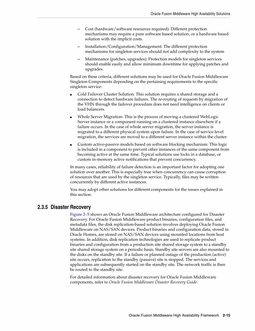
Oracle Fusion Middleware High Availability Solutions
Oracle Fusion Middleware High Availability Framework 2-15
– Cost (hardware/software resources required): Different protection mechanisms may require a pure software based solution, or a hardware based solution with the implicit costs.
– Installation/Configuration/Management: The different protection mechanisms for singleton services should not add complexity to the system
– Maintenance (patches, upgrades): Protection models for singleton services should enable easily and allow minimum downtime for applying patches and upgrades.
Based on these criteria, different solutions may be used for Oracle Fusion Middleware Singleton Components depending on the pertaining requirements to the specific singleton service:
■ Cold Failover Cluster Solution: This solution requires a shared storage and a connection to detect hardware failures. The re-routing of requests by migration of the VHN through the failover procedure does not need intelligence on clients or load balancers.
■ Whole Server Migration- This is the process of moving a clustered WebLogic Server instance or a component running on a clustered instance elsewhere if a failure occurs. In the case of whole server migration, the server instance is migrated to a different physical system upon failure. In the case of service-level migration, the services are moved to a different server instance within the cluster.
■ Custom active-passive models based on software blocking mechanism: This logic is included in a component to prevent other instances of the same component from becoming active at the same time. Typical solutions use locks in a database, or custom in-memory active notifications that prevent concurrency.
In many cases, reliability of failure detection is an important factor for adopting one solution over another. This is especially true when concurrency can cause corruption of resources that are used by the singleton service. Typically, files may be written concurrently by different active instances.
You may adopt other solutions for different components for the issues explained in this section.
2.3.5 Disaster RecoveryFigure 2–5 shows an Oracle Fusion Middleware architecture configured for Disaster Recovery. For Oracle Fusion Middleware product binaries, configuration files, and metadata files, the disk replication-based solution involves deploying Oracle Fusion Middleware on NAS/SAN devices. Product binaries and configuration data, stored in Oracle Homes, are stored on NAS/SAN devices using mounted locations from host systems. In addition, disk replication technologies are used to replicate product binaries and configuration from a production site shared storage system to a standby site shared storage system on a periodic basis. Standby site servers are also mounted to the disks on the standby site. If a failure or planned outage of the production (active) site occurs, replication to the standby (passive) site is stopped. The services and applications are subsequently started on the standby site. The network traffic is then be routed to the standby site.
For detailed information about disaster recovery for Oracle Fusion Middleware components, refer to Oracle Fusion Middleware Disaster Recovery Guide.

Protection from Planned and Unplanned Down Time
2-16 Oracle Fusion Middleware High Availability Guide
Figure 2–5 Production and Standby Site for Oracle Fusion Middleware Disaster Recovery Topology
2.4 Protection from Planned and Unplanned Down TimeThe following tables list possible planned and unplanned downtime and suggested solutions for these downtime possibilities. Table 2–1 describes planned downtime:
Table 2–1 Planned Down Time Solutions
Operations Solutions
Deploying and redeploying applications
Hot Deployment
Production / Active Site Standby / Passive Site
PRODSTOR
FirewallDMZ (Public Zone)Web Tier
WebHosts
ApplicationCluster
SecurityCluster
DiscReplication
OracleData Guard
SharedStorageSystem
DatabaseCluster
FirewallDMZ Secure Zone(Application Tier)
FirewallIntranet(Data Tier)
Internet
Application
Database
SecurityWeb
WANLoad Balancer
WEBHOST1 WEBHOST2
APPHOST1 APPHOST2
OIDHOST1 OIDHOST2
DBHOST1 DBHOST2
Load Balancer
STBYSTOR
WebHosts
ApplicationCluster
SecurityCluster
SharedStorageSystem
DatabaseCluster
Application
Database
SecurityWeb
Load Balancer
WEBHOST1 WEBHOST2
APPHOST1 APPHOST2
OIDHOST1 OIDHOST2
DBHOST1 DBHOST2
Load Balancer

Protection from Planned and Unplanned Down Time
Oracle Fusion Middleware High Availability Framework 2-17
Table 2–2 describes unplanned downtime:
Patching Rolling Patching
Configuration Changes Online configuration Changes
Change Notification
Batching of changes
Deferred Activation
Scalability and Topology Extensions
Cluster Scale-Out
Table 2–2 Unplanned Down Time Solutions
Failures Solutions
Software Failure Death Detection and restart using Node Manager for Java EE and OPMN for system components.
Server Clusters & Load Balancing
Cold Failover Clusters
Server Migration
Service Migration
State Replication and Replica aware Stubs
Hardware Failure Server Clusters & Load Balancing
Server Migration
Data Failure
Human Error
Backup and Recovery
Site Disaster Oracle Fusion Middleware Disaster Recovery Solution
Note: The architectures and deployment procedures defined in this guide enable simple clustered deployments. The procedures described in these chapters can be used as a building block to enable this and other similar high availability topologies for these Fusion Middleware components. It is also expected that production deployments will use other required procedures, such as associating security policies with a centralized LDAP server. For complete details of secured, multi-tiered architecture, and deployment procedures, please refer to the Enterprise Deployment Guide for the component you are configuring.
Table 2–1 (Cont.) Planned Down Time Solutions
Operations Solutions

Protection from Planned and Unplanned Down Time
2-18 Oracle Fusion Middleware High Availability Guide

3
High Availability for WebLogic Server 3-1
3High Availability for WebLogic Server
This chapter describes the Oracle WebLogic Server high availability capabilities that provide Oracle Fusion Middleware high availability.
■ Section 3.1, "What Is a WebLogic Server Cluster?"
■ Section 3.2, "WebLogic Server Clusters and WebLogic Server Domains"
■ Section 3.3, "Benefits of Clustering"
■ Section 3.4, "Key Capabilities of a Cluster"
■ Section 3.5, "Types of Objects That Can Be Clustered"
■ Section 3.6, "Communications in a Cluster"
■ Section 3.7, "Cluster-Wide JNDI Naming Service"
■ Section 3.8, "Failover and Replication in a Cluster"
■ Section 3.9, "Whole Server Migration"
■ Section 3.10, "JMS and JTA High Availability"
■ Section 3.11, "Administration Server and Node Manager High Availability"
■ Section 3.12, "Load Balancing"
■ Section 3.13, "GridLink Data Sources"
■ Section 3.14, "Multi Data Sources"
■ Section 3.15, "Cluster Configuration and config.xml"
■ Section 3.16, "About Singleton Services"
■ Section 3.17, "WebLogic Server and LDAP High Availability"
For complete documentation of WebLogic Server clustering, see Oracle Fusion Middleware Using Clusters for Oracle WebLogic Server.
3.1 What Is a WebLogic Server Cluster?A WebLogic Server cluster consists of multiple WebLogic Server server instances running simultaneously and working together to provide increased scalability and reliability. A cluster appears to clients to be a single WebLogic Server instance. The server instances that constitute a cluster can run on the same system, or be located on different systems. You can increase a cluster's capacity by adding additional server instances to the cluster on an existing system, or you can add systems to the cluster to host the incremental server instances. Each server instance in a cluster must run the same version of WebLogic Server.

WebLogic Server Clusters and WebLogic Server Domains
3-2 Oracle Fusion Middleware High Availability Guide
3.2 WebLogic Server Clusters and WebLogic Server DomainsA cluster is part of a particular WebLogic Server domain. A domain is an interrelated set of WebLogic Server resources that are managed as a unit. A domain includes one or more WebLogic Server instances, which can be clustered, non-clustered, or a combination of clustered and non-clustered instances. A domain can include multiple clusters. A domain also contains the application components deployed in the domain and the resources and services required by those application components and the server instances in the domain. Examples of the resources and services used by applications and server instances include system definitions, optional network channels, connectors, and startup classes.
In each domain, one WebLogic Server instance acts as the Administration Server—the server instance which configures, manages, and monitors all other server instances and resources in the domain. Each Administration Server manages one domain only. If a domain contains multiple clusters, each cluster in the domain has the same Administration Server.
All server instances in a cluster must reside in the same domain; you cannot split a cluster over multiple domains. Similarly, you cannot share a configured resource or subsystem between domains. For example, if you create a JDBC connection pool in one domain, you cannot use it with a server instance or cluster in another domain. Instead, you must create a similar connection pool in the second domain.
Clustered WebLogic Server instances behave similarly to non-clustered instances, except that they provide failover and load balancing. The process and tools you use to configure clustered WebLogic Server instances are the same as those to configure non-clustered instances. However, to achieve the load balancing and failover benefits that clustering enables, you must adhere to certain guidelines for cluster configuration.
3.3 Benefits of ClusteringA WebLogic Server cluster provides these benefits:
■ Scalability
The capacity of an application deployed on a WebLogic Server cluster can be increased dynamically to meet demand. You can add server instances to a cluster without interruption of service—the application continues to run without affecting clients and end users.
■ High Availability
In a WebLogic Server cluster, application processing can continue when a server instance fails. You cluster application components by deploying them on multiple server instances in the cluster—so, if a server instance on which a component is running fails, another server instance on which that component is deployed can continue application processing.
The choice to cluster WebLogic Server instances is transparent to application developers and clients. However, understanding the technical infrastructure that enables clustering helps programmers and administrators maximize the scalability and availability of their applications.
3.4 Key Capabilities of a ClusterThis section defines key clustering capabilities that enable scalability and high availability. This section includes the following topics:

Key Capabilities of a Cluster
High Availability for WebLogic Server 3-3
■ Section 3.4.1, "Application Failover"
■ Section 3.4.2, "Server Migration"
■ Section 3.4.3, "Load Balancing"
3.4.1 Application FailoverFailover means that when an application component, typically referred to as an object in the following sections, doing a particular job—some set of processing tasks—becomes unavailable for any reason, a copy of the failed object finishes the job.
For the new object to be able to take over for the failed object, there must be:
■ A copy of the failed object available to take over the job.
■ Information, available to other objects and the program that manages failover, defining the location and operational status of all objects—so that it can be determined that the first object failed before finishing its job.
■ Information, available to other objects and the program that manages failover, about the progress of jobs in process—so that an object taking over an interrupted job knows how much of the job was completed before the first object failed. For example: what data changed and what steps in the process were completed.
WebLogic Server uses standards-based communication techniques and facilities— including IP sockets and the Java Naming and Directory Interface (JNDI)—to share and maintain information about the availability of objects in a cluster. These techniques allow WebLogic Server to determine that an object stopped before finishing its job, and where there is a copy of the object to complete the interrupted job.
Information about what has been done on a job is called state. WebLogic Server maintains state information using techniques called session replication and replica-aware stubs. When an object unexpectedly stops doing its job, replication techniques enable a copy of the object to pick up where the failed object stopped and finish the job.
3.4.2 Server MigrationWebLogic Server supports automatic and manual migration of a clustered server instance from one system to another. The server migration process relocates a Managed Server in its entirety, including IP addresses and hosted applications, to one of a predefined set of available host systems. This feature is designed for environments with requirements for high availability. Server migration is useful for:
■ Ensuring uninterrupted availability of singleton services—services that must run on only a single server instance at any given time, when the hosting server instance fails. A Managed Server configured for automatic migration automatically migrates to another system if a failure occurs.
■ Facilitating the process of relocating a Managed Server and all services it hosts, as part of a planned system administration process. You initiate the Managed Server migration from the Administration Console or command line.
3.4.3 Load BalancingLoad balancing is the even distribution of jobs and associated communications across the computing and networking resources in your environment. Load balancing requires:
■ Multiple copies of an object that can do a particular job.

Types of Objects That Can Be Clustered
3-4 Oracle Fusion Middleware High Availability Guide
■ Information about the location and operational status of all objects.
WebLogic Server allows objects to be clustered—deployed on multiple server instances—so that there are alternative objects to do the same job. WebLogic Server shares and maintains the availability and location of deployed objects using unicast, IP sockets, and JNDI.
3.5 Types of Objects That Can Be ClusteredA clustered application or application component is one that is available on multiple WebLogic Server instances in a cluster. If an object is clustered, failover and load balancing for that object is available. Deploy objects homogeneously—to every server instance in your cluster—to simplify cluster administration, maintenance, and troubleshooting.
Web applications can consist of different types of objects, including Enterprise Java Beans (EJBs), servlets, and Java Server Pages (JSPs). Each object type has a unique set of behaviors related to control, invocation, and how it functions within an application. For this reason, the methods that WebLogic Server uses to support clustering—and hence to provide load balancing and failover—can vary for different types of objects. In a WebLogic Server deployment, you can cluster these object types:
■ Servlets
■ JSPs
■ EJBs
■ Remote Method Invocation (RMI) objects
■ Java Messaging Service (JMS) destinations
Different object types can have certain common behaviors. When this is the case, the clustering support and implementation considerations for similar object types may be same. The following sections combine explanations and instructions for these objects:
■ Servlets and JSPs
■ EJBs and RMI objects
3.6 Communications in a ClusterWebLogic Server instances in a cluster communicate with one another using two basic network technologies:
■ IP sockets, which are the conduits for peer-to-peer communication between clustered server instances.
■ IP unicast or multicast, which server instances use to broadcast availability of services and heartbeats that indicate continued availability. When creating a new cluster, Oracle recommends that you use unicast for messaging within a cluster. For backward compatibility with previous versions of WebLogic Server, you must use multicast for communications between clusters.
Note: When using the unicast protocol for a WebLogic Server cluster, servers that are part of the cluster must specify a listen address. The servers cannot be listening on ANY, which is equivalent to leaving the Listen Address field in the Administration Console blank.

Failover and Replication in a Cluster
High Availability for WebLogic Server 3-5
3.7 Cluster-Wide JNDI Naming ServiceClients of a non-clustered WebLogic Server server instance access objects and services by using a JNDI-compliant naming service. The JNDI naming service contains a list of the public services that the server instance offers, organized in a tree structure. A WebLogic Server instance offers a new service by binding into the JNDI tree a name that represents the service. Clients obtain the service by connecting to the server instance and looking up the bound name of the service.
Server instances in a cluster use a cluster-wide JNDI tree. A cluster-wide JNDI tree is similar to a single server instance JNDI tree, insofar as the tree contains a list of available services. In addition to storing the names of local services, however, the cluster-wide JNDI tree stores the services offered by clustered objects (EJBs and RMI classes) from other server instances in the cluster.
Each WebLogic Server instance in a cluster creates and maintains a local copy of the logical cluster-wide JNDI tree. Creation of a cluster-wide JNDI tree begins with the local JNDI tree bindings of each server instance. As a server instance boots (or as new services are dynamically deployed to a running server instance), the server instance first binds the implementations of those services to the local JNDI tree. The implementation is bound into the JNDI tree only if no other service of the same name exists.
Once the server instance successfully binds a service into the local JNDI tree, additional steps are performed for clustered objects that use replica-aware stubs. After binding the clustered object's implementation into the local JNDI tree, the server instance sends the object's stub to other members of the cluster. Other members of the cluster monitor the multicast or unicast address to detect when remote server instances offer new services.
3.8 Failover and Replication in a ClusterFor a cluster to provide high availability it must be able to recover from service failures. WebLogic Server instances in a cluster detect failures of their peer server instances by monitoring:
■ Socket connections to a peer server
WebLogic Server instances monitor the use of IP sockets between peer server instances as an immediate method of detecting failures. If a server connects to one of its peers in a cluster and begins transmitting data over a socket, an unexpected closure of that socket causes the peer server to be marked as "failed," and its associated services are removed from the JNDI naming tree.
■ Regular server heartbeat messages
If clustered server instances do not have opened sockets for peer-to-peer communication, failed servers may also be detected via the WebLogic Server heartbeat. All server instances in a cluster use multicast or unicast to broadcast regular server heartbeat messages to other members of the cluster.
Each heartbeat message contains data that uniquely identifies the server that sends the message. Servers broadcast their heartbeat messages at regular intervals of 10 seconds. In turn, each server in a cluster monitors the multicast or unicast address to ensure that all peer servers' heartbeat messages are being sent.
If a server monitoring the multicast or unicast address misses three heartbeats from a peer server (i.e., if it does not receive a heartbeat from the server for 30 seconds or longer), the monitoring server marks the peer server as "failed." It then

Whole Server Migration
3-6 Oracle Fusion Middleware High Availability Guide
updates its local JNDI tree, if necessary, to retract the services that were hosted on the failed server.
3.8.1 Session ReplicationUser session data can be stored in two standard ways in a Java EE application: stateful session EJBs or HTTP sessions. By themselves, they rarely impact cluster scalability. However, when coupled with a session replication mechanism required to provide high-availability, bottlenecks are introduced. If a Java EE application has Web and EJB components, you should store user session data in HTTP sessions:
■ HTTP session management provides more options for handling fail-over, such as replication, a shared database or file.
■ Superior scalability.
■ Replication of the HTTP session state occurs outside of any transactions. Stateful session bean replication occurs in a transaction which is more resource intensive.
■ The HTTP session replication mechanism is more sophisticated and provides optimizations a wider variety of situations than stateful session bean replication.
3.9 Whole Server MigrationIn a WebLogic Server cluster, most services are deployed homogeneously on all server instances in the cluster, enabling transparent failover from one server to another. In contrast, pinned services such as JMS and the JTA transaction recovery system are targeted at individual server instances within a cluster—for these services, WebLogic Server supports failure recovery with migration as opposed to failover.
Migration in WebLogic Server is the process of moving a clustered WebLogic Server instance or a component running on a clustered instance elsewhere if failure occurs. In the case of whole server migration, the server instance is migrated to a different physical system upon failure. In the case of service-level migration, the services are moved to a different server instance within the cluster.
WebLogic Server provides a feature for making JMS and the JTA transaction system highly available: migratable servers. Migratable servers provide for both automatic and manual migration at the server-level, rather than the service level.
When a migratable server becomes unavailable for any reason, for example, if it hangs, loses network connectivity, or its host system fails—migration is automatic. Upon failure, a migratable server automatically restarts on the same system if possible. If the migratable server cannot restart on the system it failed on, it is migrated to another system. In addition, an administrator can manually initiate migration of a server instance.
3.9.1 Node Manager's Role in Whole Server MigrationServer migration requires Node Manager—it must run on each system that hosts, or is intended to host.
Node Manager supports server migration in these ways:
■ You must use Node Manager for the initial startup of migratable servers.
When you initiate the startup of a Managed Server from the Administration Console, the Administration Server uses Node Manager to start the server instance. You can also invoke Node Manager to start the server instance using the

Whole Server Migration
High Availability for WebLogic Server 3-7
stand-alone Node Manager client; however, the Administration Server must be available so that the Managed Server can obtain its configuration.
■ You must use Node Manager to suspend, shutdown, or force shutdown of migratable servers.
■ Node Manager tries to restart a migratable server with an expired lease on the system where it was running at the time of failure.
Node Manager performs the steps in the server migrate process by running customizable shell scripts, provided with WebLogic Server, that start, restart and stop servers; migrate IP addresses; and mount and unmount disks. The scripts are available for Solaris and Linux.
– In an automatic migration, the cluster master invokes Node Manager to perform the migration.
– In a manual migration, the Administration Server invokes Node Manager to perform the migration.
3.9.2 Server Migration Processes and CommunicationsThe following sections describe key processes in a cluster that contains migratable servers:
■ Section 3.9.2.1, "Startup Process in a Cluster with Migratable Servers"
■ Section 3.9.2.2, "Automatic Whole Server Migration Process"
■ Section 3.9.2.3, "Manual Whole Server Migration Process"
■ Section 3.9.2.4, "Administration Server's Role in Whole Server Migration"
■ Section 3.9.2.5, "Migratable Server Behavior in a Cluster"
■ Section 3.9.2.6, "Cluster Master's Role in Whole Server Migration"
3.9.2.1 Startup Process in a Cluster with Migratable ServersFigure 3–1 shows the processing and communications that occur during startup of a cluster that contains migratable servers.
The example cluster contains two Managed Servers, both of which are migratable. The Administration Server and the two Managed Servers each run on different machines. A fourth machine is available as a backup—in the event that one of the migratable servers fails. Node Manager is running on the backup machine and on each machine with a running migratable server.
Note: Migration of a server instance that was not initially started with Node Manager will fail.

Whole Server Migration
3-8 Oracle Fusion Middleware High Availability Guide
Figure 3–1 Startup of Cluster with Migratable Servers
These are the key steps that occur during startup of the cluster illustrated in Figure 3–1:
1. The administrator starts up the cluster.
2. The Administration Server invokes Node Manager on Machines B and C to start Managed Servers 1 and 2, respectively. See Section 3.9.2.4, "Administration Server's Role in Whole Server Migration."
3. The Node Manager on each machine starts up the Managed Server that runs there. See Section 3.9.1, "Node Manager's Role in Whole Server Migration."
4. Managed Servers 1 and 2 contact the Administration Server for their configuration. See Section 3.9.2.5, "Migratable Server Behavior in a Cluster."
5. Managed Servers 1 and 2 cache the configuration they started up.
6. Managed Servers 1 and 2 each obtain a migratable server lease in the lease table. Because Managed Server 1 starts up first, it also obtains a cluster master lease. See

Whole Server Migration
High Availability for WebLogic Server 3-9
Section 3.9.2.6, "Cluster Master's Role in Whole Server Migration."
7. Managed Server 1 and 2 periodically renew their leases in the lease table, proving their health and liveness.
3.9.2.2 Automatic Whole Server Migration ProcessFigure 3–2 shows the automatic migration process after the failure of the machine hosting Managed Server 2.
Figure 3–2 Automatic Migration of a Failed Server
1. Machine C, which hosts Managed Server 2, fails.
2. Upon its next periodic review of the lease table, the cluster master detects that Managed Server 2's lease has expired. See Section 3.9.2.6, "Cluster Master's Role in Whole Server Migration."
3. The cluster master tries to contact Node Manager on Machine C to restart Managed Server 2, but fails, because Machine C is unreachable.

Whole Server Migration
3-10 Oracle Fusion Middleware High Availability Guide
4. The cluster master contacts Node Manager on Machine D, which is configured as an available host for migratable servers in the cluster.
5. Node Manager on Machine D starts Managed Server 2. See Section 3.9.1, "Node Manager's Role in Whole Server Migration."
6. Managed Server 2 starts up and contacts the Administration Server to obtain its configuration.
7. Managed Server 2 caches the configuration it started up with.
8. Managed Server 2 obtains a migratable server lease.
During migration, the clients of the migrating Managed Server may have a brief interruption in service; it may be necessary to reconnect. On Solaris and Linux operating systems, you reconnect using ifconfig command. The clients of a migrated server do not need to know the particular machine the server migrates to.
When a machine that previously hosted a server instance that was migrated becomes available again, the reversal of the migration process—migrating the server instance back to its original host machine—is known as failback. WebLogic Server does not automate the failback process. You can accomplish failback by manually restoring the server instance to its original host.
The general procedures to restore a server to its original host are:
■ Gracefully shutdown the new instance of the server.
■ After you restart the failed machine, restart Node Manager and the managed server.
The exact procedures you follow depend on your server and network environment.
3.9.2.3 Manual Whole Server Migration ProcessFigure 3–3 shows what happens when an administrator manually migrates a migratable server.
Note: If the Managed Server 2's lease had expired because it was hung, and Machine C was reachable, the cluster master would use Node Manager to restart Managed Server 2 on Machine C.

Whole Server Migration
High Availability for WebLogic Server 3-11
Figure 3–3 Manual Whole Server Migration
1. An administrator uses the Administration Console to initiate the migration of Managed Server 2 from Machine C to Machine B.
2. The Administration Server contacts Node Manager on Machine C. See Section 3.9.2.4, "Administration Server's Role in Whole Server Migration."
3. Node Manager on Machine C stops Managed Server 2.
4. Managed Server 2 removes its row from the lease table.
5. The Administration Server invokes Node Manager on Machine B.
6. Node Manager on Machine B starts Managed Server 2.
7. Managed Server 2 obtains its configuration from the Administration Server.
8. Managed Server 2 caches the configuration it started up with.
9. Managed Server 2 adds a row to the lease table.
3.9.2.4 Administration Server's Role in Whole Server MigrationIn a cluster that contains migratable servers, the Administration Server invokes Node Manager on each system:
■ That hosts cluster members to start the migratable servers. This is a prerequisite for server migratability—if Node Manager did not initially start a server instance, you cannot migrate the server.
■ Involved in a manual migration process to stop and start the migratable server.

Whole Server Migration
3-12 Oracle Fusion Middleware High Availability Guide
■ That hosts cluster members to stop server instances during a normal shutdown. This is a prerequisite for server migratability—if a server instance is shut down directly without using Node Manager, when the cluster master detects that the server instance is not running, it will call Node Manager to restart it.
The Administration Server also provides its regular domain management functionality, persisting configuration updates issued by an administrator and providing a run-time view of the domain, including the migratable servers it contains.
3.9.2.5 Migratable Server Behavior in a ClusterA migratable server is a clustered Managed Server that is configured as migratable. These are the key behaviors of a migratable server:
■ If you are using a database to manage leasing information, during startup and restart by Node Manager, a migratable server adds a row to the lease table. The row for a migratable server contains a timestamp, and the machine where it is running.
■ When using a database to manage leasing information, a migratable server adds a row to the database as a result of startup, it tries to take on the role of cluster master, and succeeds if it is the first server instance to join the cluster.
■ Periodically, the server renews its "lease" by updating the timestamp in the lease table.
By default a migratable server renews its lease every 30,000 milliseconds—the product of two configurable ServerMBean properties:
– HealthCheckIntervalMillis, which by default is 10,000.
– HealthCheckPeriodsUntilFencing, which by default is 3.
■ If a migratable server fails to reach the lease table and renew its lease before the lease expires, it terminates as quickly as possible using a Java System.exit—in this case, the lease table still contains a row for that server instance. For information about how this relates to automatic migration, see Section 3.9.2.6, "Cluster Master's Role in Whole Server Migration."
■ During operation, a migratable server listens for heartbeats from the cluster master. When it detects that the cluster master is not sending heartbeats, it attempts to take over the role of cluster master, and succeeds if no other server instance has claimed that role.
3.9.2.6 Cluster Master's Role in Whole Server MigrationIn a cluster that contains migratable servers, one server instance acts as the cluster master. Its role is to orchestrate the server migration process. Any server instance in the cluster can serve as the cluster master. When you start a cluster that contains migratable servers, the first server to join the cluster becomes the cluster master and starts up the cluster manager service. If a cluster does not include at least one migratable server, it does not require a cluster master and the cluster master service does not start up. In the absence of a cluster master, migratable servers can continue to operate, but server migration is not possible. Key cluster master functions are:
■ Issues periodic heartbeats to the other servers in the cluster.
■ Periodically reads the lease table to verify that each migratable server has a current lease. An expired lease indicates to the cluster master that the migratable server should be restarted.

JMS and JTA High Availability
High Availability for WebLogic Server 3-13
■ Upon determining that a migratable server's lease is expired, waits for period specified by the FencingGracePeriodMillis on the ClusterMBean, and then tries to invoke the Node Manager process on the machine that hosts the migratable server whose lease is expired, to restart the migratable server.
■ If unable to restart a migratable server whose lease has expired on its current machine, the cluster master selects a target machine in this fashion:
■ If you configure a list of preferred destination machines for the migratable server, the cluster master chooses a machine on that list in the order the machines are listed. Otherwise, the cluster master chooses a machine on the list of those configured as available for hosting migratable servers in the cluster.
A list of machines that can host migratable servers can be configured at two levels: for the cluster as a whole, and for an individual migratable server. You can define a machine list at both levels. You must define a machine list at least one level.
■ To migrate a server instance to a new machine, the cluster master invokes the Node Manager process on the target machine to create a process for the server instance.
The time required to perform the migration depends on the server configuration and startup time.
■ The maximum time taken for cluster master to restart the migratable server is (HealthCheckPeriodsUntilFencing * HealthCheckIntervalMillis) + FencingGracePeriodMillis.
■ The total time before the server becomes available for client requests depends on the server startup time and the application deployment time.
3.10 JMS and JTA High AvailabilityYou can configure JMS and JTA services for high availability by using a migratable target, a special target that can migrate from one server in a cluster to another. A migratable target provides a way to group migratable services that should move together. When a migratable target migrates, all services the target hosts also migrate.
To configure a migratable JMS service for migration, it must be deployed to a migratable target. A migratable target specifies a set of servers that can host a target, and can optionally specify a user-preferred host for the services and an ordered list of candidate backup servers should the preferred server fail. Only one of these servers can host the migratable target at any one time.
After you configure a service to use a migratable target, the service is independent from the server member that is currently hosting it. For example, if a JMS server with a deployed JMS queue is configured to use a migratable target then the queue is independent of when a specific server member is available. That is, the queue is always available when the migratable target is hosted by any server in the cluster.
An administrator can manually migrate pinned migratable services from one server instance to another in the cluster in response to a server failure or as part of regularly scheduled maintenance. If you do not configure a migratable target in the cluster, migratable services can be migrated to any WebLogic Server instance in the cluster.
3.10.1 User-Preferred Servers and Candidate ServersWhen deploying a JMS service to the migratable target, you can select a user-preferred server (UPS) target to host the service. When configuring a migratable target, you can also specify constrained candidate servers (CCS) that can host the service if the

JMS and JTA High Availability
3-14 Oracle Fusion Middleware High Availability Guide
user-preferred server fails. If the migratable target does not specify a constrained candidate server, you can migrate the JMS server to any available server in the cluster.
WebLogic Server enables you to create separate migratable targets for JMS services. This allows you to always keep each service running on a different server in the cluster, if necessary. Conversely, you can configure the same selection of servers as the constrained candidate servers for both JTA and JMS, to ensure that the services remain co-located on the same server in the cluster.
3.10.2 Considerations for Using File Stores on NFSIf JMS messages and transaction logs are stored on an NFS-mounted directory, Oracle strongly recommends that you verify the behavior of a server restart after abrupt machine failures. Depending on the NFS implementation, different issues can arise post failover/restart.
To verify server restart behavior, abruptly shut down the node that hosts WebLogic servers while the servers are running.
■ If you configured the server for server migration, it should start automatically in failover node after the failover period.
■ If you did not configure the server for server migration, you can manually restart the WebLogic Server on the same host after the node completely reboots.
If WebLogic Server does not restart after abrupt machine failure, the following error entry may appear in server log files:
<MMM dd, yyyy hh:mm:ss a z> <Error> <Store> <BEA-280061> <The persistent store "_WLS_server_soa1" could not be deployed: weblogic.store.PersistentStoreException: java.io.IOException: [Store:280021]There was an error while opening the file store file "_WLS_SERVER_SOA1000000.DAT" weblogic.store.PersistentStoreException: java.io.IOException: [Store:280021]There was an error while opening the file store file "_WLS_SERVER_SOA1000000.DAT" at weblogic.store.io.file.Heap.open(Heap.java:168) at weblogic.store.io.file.FileStoreIO.open(FileStoreIO.java:88)...java.io.IOException: Error from fcntl() for file locking, Resourcetemporarily unavailable, errno=11
This error occurs when the NFSv3 system does not release locks on the file stores. WebLogic Server maintains locks on files that store JMS data and transaction logs to prevent data corruption that can occur if you accidentally start two instances of the same managed server. Because the NFSv3 storage device doesn't track lock owners, NFS holds the lock indefinitely if a lock owner fails. As a result, after abrupt machine failure followed by a restart, subsequent attempts by WebLogic Server to acquire locks may fail.
How you resolve this error depends on your NFS environment: (See Oracle Fusion Middleware Release Notes for updates on this topic.)
■ For NFSv4 environments, you can set a tuning parameter on the NAS server to release locks within the approximate time required to complete server migration; you do not need to follow the procedures in this section. See your storage vendor's documentation for information on locking files stored in NFS-mounted directories on the storage device, and test the results.

JMS and JTA High Availability
High Availability for WebLogic Server 3-15
■ For NFSv3 environments, the following sections describe how to disable WebLogic file locking mechanisms for: the default file store, a custom file store, a JMS paging file store, a diagnostics file store.
Disabling File Locking for the Default File StoreTo disable file locking for the default file store using the Administration Console:
1. If necessary, click Lock & Edit in the Change Center (upper left corner) of the Administration Console to get an Edit lock for the domain.
2. In the Domain Structure tree, expand the Environment node and select Servers.
3. In the Summary of Servers list, select the server you want to modify.
4. Select the Configuration > Services tab.
5. Scroll down to the Default Store section and click Advanced.
6. Scroll down and deselect the Enable File Locking check box.
7. Click Save. If necessary, click Activate Changes in the Change Center.
8. Restart the server you modified for the changes to take effect.
The resulting config.xml entry looks like the following:
<server> <name>examplesServer</name> ... <default-file-store> <synchronous-write-policy>Direct-Write</synchronous-write-policy> <io-buffer-size>-1</io-buffer-size> <max-file-size>1342177280</max-file-size> <block-size>-1</block-size> <initial-size>0</initial-size> <file-locking-enabled>false</file-locking-enabled> </default-file-store> </server>
WARNING: NFSv3 file locking prevents severe file corruptions that occur if more than one managed server writes to the same file store at any point in time.
If you disable NFSv3 file locking, you must implement administrative procedures / policies to ensure that only one managed server writes to a specific file store. Corruption can occur with two managed servers in the same cluster or different clusters, on the same node or different nodes, or on the same domain or different domains.
Your policies could include: never copy a domain, never force a unique naming scheme of WLS-configured objects (servers, stores), each domain must have its own storage directory, no two domains can have a store with the same name that references the same directory.
If you configure a managed server using a file store for server migration, always configure the database- based leasing option. This option enforces additional locking mechanisms using database tables and prevents automated restart of more than one instance of a particular managed server.

JMS and JTA High Availability
3-16 Oracle Fusion Middleware High Availability Guide
Disabling File Locking for a Custom File StoreTo disable file locking for a custom file store using the Administration Console:
1. If necessary, click Lock & Edit in the Change Center (upper left corner) of the Administration Console to get an Edit lock for the domain.
2. In the Domain Structure tree, expand the Services node and select Persistent Stores.
3. In the Summary of Persistent Stores list, select the custom file store you want to modify.
4. On the Configuration tab for the custom file store, click Advanced.
5. Scroll down and deselect the Enable File Locking check box.
6. Click Save. If necessary, click Activate Changes in the Change Center.
7. If the custom file store was in use, restart the server for the changes to take effect.
The resulting config.xml entry looks like the following:
<file-store> <name>CustomFileStore-0</name> <directory>C:\custom-file-store</directory> <synchronous-write-policy>Direct-Write</synchronous-write-policy> <io-buffer-size>-1</io-buffer-size> <max-file-size>1342177280</max-file-size> <block-size>-1</block-size> <initial-size>0</initial-size> <file-locking-enabled>false</file-locking-enabled> <target>examplesServer</target> </file-store>
Disabling File Locking for a JMS Paging File StoreTo disable file locking for a JMS paging file store using the Administration Console:
1. If necessary, click Lock & Edit in the Change Center (upper left corner) of the Administration Console to get an Edit lock for the domain.
2. In the Domain Structure tree, expand the Services node, expand the Messaging node, and select JMS Servers.
3. In the Summary of JMS Servers list, select the JMS server you want to modify.
4. On the Configuration > General tab for the JMS Server, scroll down and deselect the Paging File Locking Enabled check box.
5. Click Save. If necessary, click Activate Changes in the Change Center.
6. Restart the server you modified for the changes to take effect.
The resulting config.xml file entry will look like the following:
<jms-server> <name>examplesJMSServer</name> <target>examplesServer</target> <persistent-store>exampleJDBCStore</persistent-store> ... <paging-file-locking-enabled>false</paging-file-locking-enabled> ... </jms-server>

Administration Server and Node Manager High Availability
High Availability for WebLogic Server 3-17
Disabling File Locking for a Diagnostics File StoreTo disable file locking for a Diagnostics file store using the Administration Console:
1. If necessary, click Lock & Edit in the Change Center (upper left corner) of the Administration Console to get an Edit lock for the domain.
2. In the Domain Structure tree, expand the Diagnostics node and select Archives.
3. In the Summary of Diagnostic Archives list, select the server name of the archive that you want to modify.
4. On the Settings for [server_name] page, deselect the Diagnostic Store File Locking Enabled check box.
5. Click Save. If necessary, click Activate Changes in the Change Center.
6. Restart the server you modified for the changes to take effect.
The resulting config.xml file will look like this:
<server> <name>examplesServer</name> ... <server-diagnostic-config> <diagnostic-store-dir>data/store/diagnostics</diagnostic-store-dir> <diagnostic-store-file-locking-enabled>false</diagnostic-store-file-locking-enabled> <diagnostic-data-archive-type>FileStoreArchive</diagnostic-data-archive-type> <data-retirement-enabled>true</data-retirement-enabled> <preferred-store-size-limit>100</preferred-store-size-limit> <store-size-check-period>1</store-size-check-period> </server-diagnostic-config> </server>
3.11 Administration Server and Node Manager High AvailabilityThe Administration Server is the WebLogic Server instance that configures and manages the WebLogic Server instances in its domain.
A domain can include multiple WebLogic Server clusters and non-clustered WebLogic Server instances. A domain can consist of only one WebLogic Server instance—however, in this case that sole server instance would be an Administration Server because each domain must have exactly one Administration Server.
There are a variety of ways to invoke the services of the Administration Server to accomplish configuration tasks. Whichever method is used, the Administration Server for a cluster must be running when you modify the configuration.
Note: Oracle recommends that you set the Administration Server listen address to the hostname that its clients need to access it on, particularly for systems with multiple Middleware homes or Oracle homes.

Load Balancing
3-18 Oracle Fusion Middleware High Availability Guide
3.11.1 Administration Server FailureThe failure of an Administration Server for a domain does not affect the operation of managed servers in the domain. If an Administration Server for a domain becomes unavailable while the server instances it manages—clustered or otherwise—are up and running, those managed servers continue to run. If the domain contains clustered server instances, the load balancing and failover capabilities supported by the domain configuration remain available, even if the Administration Server fails.
For instructions on re-starting an Administration Server, see the Oracle Fusion Middleware Using Clusters for Oracle Server.
3.11.2 Node Manager FailureIf Node Manager fails or is explicitly shut down, upon restart, it determines the server instances that were under its control when it exited. Node Manager can restart any failed server instances as needed.
3.12 Load BalancingLoad balancing configuration consists of three pieces of information: the load-balancing algorithm to use, an indicator of whether local affinity should be applied, and weights that are assigned to each member of the topology to influence any routing algorithms that use weights.
The load-balancing algorithm specifies how requests are load balanced across components. Oracle Fusion Middleware uses three load-balancing methods:
■ Round Robin - Requests are balanced across a list of available servers by selecting from the list sequentially.
■ Random - Requests are balanced across a list of available servers by selecting a random server on each request.
■ Weighted - Requests are balanced across a list of available servers using weights assigned to each server to determine the percentage of requests sent to each
Local affinity determines whether clients show a preference to servers that run on the same machine to avoid network latency. If the flag is set to true, then requests are routed across the list of servers on the local machine using the load-balancing algorithm if any local servers are available. If no local servers are available, requests are routed to all available remote servers according to the load-balancing algorithm. If local affinity is set to false, requests are routed across all available servers (local and remote) based on the load-balancing algorithm.
You configure weights as single integer values that are associated with component instances. You can assign weights to components that are not currently in a group,
Note: If an Administration Server fails because of a hardware or software failure on its host machine, other server instances on the same machine may be similarly affected. However, the failure of an Administration Server itself does not interrupt the operation of managed servers in the domain.
Note: It is advisable to run Node Manager as an operating system service, so that it restarts automatically if its host machine is restarted.

Cluster Configuration and config.xml
High Availability for WebLogic Server 3-19
however, the weight is not used unless you later configure the component as a member of a group and select the weighted load-balancing algorithm. The weight is a unitless number. The percentage of requests to be sent to each member is calculated by summing the weights of all available members and dividing the weight for each member by the sum of the weights.
3.13 GridLink Data SourcesA single GridLink data source provides connectivity between WebLogic Server and an Oracle Database Real Application Clusters (RAC). It uses the Oracle Notification Service (ONS) to respond adaptively to state changes in an Oracle RAC. It responds to FAN events to provide Fast Connection Failover (FCF), Runtime Connection Load-Balancing (RCLB), and RAC instance graceful shutdown. It also provides capabilities of Affinities.
Oracle recommends GridLink data sources when you use an Oracle RAC database. For other databases, use multi data sources for high availability.
See Using GridLink Data Sources in the Oracle Fusion Middleware Configuring and Managing JDBC Data Sources for Oracle WebLogic Server guide for more information about GridLink data sources.
3.14 Multi Data SourcesA multi data source is an abstraction around a group of data sources that provides load balancing or failover processing at the time of connection requests, between the data sources associated with the multi data source. Multi data sources are bound to the JNDI tree or local application context just like data sources are bound to the JNDI tree. Applications look up a multi data source on the JNDI tree or in the local application context (java:comp/env) just as they do for data sources, and then request a database connection. The multi data source determines which data source to use to satisfy the request depending on the algorithm selected in the multi data source configuration: load balancing or failover.
A multi data source can be thought of as a pool of data sources. Multi data sources are best used for failover or load balancing between nodes of a highly available database system, such as redundant databases or Oracle RAC.
3.15 Cluster Configuration and config.xmlThe config.xml file is an XML document that describes the WebLogic Server domain configuration. The domain element in config.xml is the top-level element, and all elements in the domain descend from the domain element. The domain element includes child elements such as the server, cluster, and application elements. These child elements may have children of their own. For example, the server element can include the child elements WebServer, SSL and Log. The Application element includes the child elements EJBComponent and WebAppComponent.
Each element has one or more configurable attributes. An attribute defined in config.dtd has a corresponding attribute in the configuration API. For example, the Server element has a ListenPort attribute, and likewise, the Weblogic.management.configuration.ServerMBean has a ListenPort attribute. Configurable attributes are readable and writable, that is, ServerMBean has a getListenPort() and a setListenPort() method.

About Singleton Services
3-20 Oracle Fusion Middleware High Availability Guide
To learn more about config.xml, see the Oracle Fusion Middleware Using Clusters for Oracle WebLogic Server.
3.16 About Singleton ServicesA singleton service is a service that must run on only a single server instance at any given time, such as JMS and the JTA transaction recovery system, when the hosting server instance fails. A managed server configured for automatic migration automatically migrates to another machine if a failure occurs.
3.17 WebLogic Server and LDAP High AvailabilityIn a high availability environment, WebLogic Server must be able to access LDAP for these reasons:
■ To access users and groups stored in LDAP for which WebLogic Server supports failover.
For information about configuring failover for LDAP authentication providers, see "Configuring Failover for LDAP Authentication Providers" in the Oracle Fusion Middleware Securing Oracle WebLogic Server manual.
■ To access the LDAP-based policy store and credential store.
For information about configuring a domain to use an LDAP-based policy store, see "Configuring a Domain to Use an LDAP-Based Policy Store" in the Oracle Fusion Middleware Application Security Guide manual.
For information about configuring a domain to use an LDAP-based credential store, see "Configuring a Domain to Use an LDAP-Based Credential Store" in the Oracle Fusion Middleware Application Security Guide manual.

4
Considerations for High Availability Oracle Database Access 4-1
4 Considerations for High Availability OracleDatabase Access
This chapter describes considerations for high availability Oracle database access.
The sections in this chapter are as follows:
■ Section 4.1, "Oracle Real Application Clusters and Fusion Middleware"
■ Section 4.2, "Protecting Idle Connections from Firewall Timeouts"
■ Section 4.3, "Troubleshooting"
■ Section 4.4, "Using SCAN Addresses with Oracle Database 11g (11.2)"
4.1 Oracle Real Application Clusters and Fusion MiddlewareMost Fusion Middleware components use a database as the persistent store for their data. You can configure the Oracle database back end in any number of high availability configurations, including Cold Failover Clusters, Oracle Real Application Clusters, Oracle Data Guard, or Oracle Streams. For more information, see the Oracle Database High Availability Overview. This chapter describes considerations for Oracle Fusion Middleware configured with a high availability Oracle database, Oracle Real Application Clusters.
Oracle Real Application Cluster (Oracle RAC) is a computing environment that harnesses the processing power of multiple, interconnected computers. Along with a collection of hardware (cluster), it unites the processing power of each component to become one robust computing environment. Oracle RAC simultaneously provides a highly scalable and highly available database for Oracle Fusion Middleware.
Every Oracle RAC instance in the cluster has equal access and authority, therefore, node and instance failure may affect performance, but doesn't result in downtime; the database service is available or can be made available on surviving server instances.
For more information on Oracle RAC, see the Oracle Real Application Clusters Administration and Deployment Guide.
Oracle Fusion Middleware provides the best integration with an Oracle database in a high availability environment. When Oracle Fusion Middleware behaves as a client for the database (either as a java or system client) it uses special communication and monitoring capabilities that provide fast failover and minimal middle tier disruption in reaction to database failure scenarios.
You can categorize Oracle Fusion Middleware components that access the database as follows:
■ Java-based components deployed to Oracle WebLogic Server

Oracle Real Application Clusters and Fusion Middleware
4-2 Oracle Fusion Middleware High Availability Guide
■ Java-based components that are standalone Java Clients
■ Non-Java components
This chapter contains the following sections:
■ Section 4.1.1, "Java-Based Oracle Fusion Middleware Components Deployed to Oracle WebLogic Server"
■ Section 4.1.2, "GridLink Data Sources and Oracle RAC"
■ Section 4.1.3, "Using Multi Data Sources with Oracle RAC"
■ Section 4.1.4, "Configuring GridLink Data Sources with Oracle RAC"
■ Section 4.1.5, "Configuring Multi Data Sources with Oracle RAC"
■ Section 4.1.6, "JDBC Clients"
4.1.1 Java-Based Oracle Fusion Middleware Components Deployed to Oracle WebLogic Server
All Oracle Fusion Middleware components deployed to Oracle WebLogic Server support Oracle RAC. For establishing connection pools, Oracle Fusion Middleware supports GridLink data sources and multi data sources for the Oracle RAC back end for both XA and non-XA JDBC drivers. Oracle Fusion Middleware deployments do not support other connection failover features supported by Oracle JDBC drivers for Oracle RAC. See component specific guides for multi data source configuration details.
When an Oracle RAC node or instance fails, WebLogic Server or the Oracle Thin driver redirect session requests to another node in the cluster. There is no failover of existing connections, however, new connection requests from the application are managed using existing connections in the Oracle WebLogic pool or by new connections to the working Oracle RAC instance. When the database is the transaction manager, in-flight transactions typically roll back. When the WebLogic Server is the transaction manager, in-flight transactions fail over; they are driven to completion or rolled back based on the transaction state when failure occurs. If the application requires load balancing across Oracle RAC nodes, WebLogic Server supports this capability by using JDBC GridLink data sources or JDBC multi data sources configured for load balancing. See Run Time Connection Load Balancing in the Oracle Fusion Middleware Configuring and Managing JDBC Data Sources for Oracle WebLogic Server guide for more information on GridLink load balancing.
4.1.2 GridLink Data Sources and Oracle RACA GridLink data source includes the features of generic data sources plus the following support for Oracle RAC:
■ Fast Connection Failover
■ Runtime Connection Load Balancing
■ Graceful Handling for Oracle RAC Outages
■ XA Affinity
■ Single Client Access Name (SCAN) Addresses
■ Secure Communication Using Oracle Wallet
Oracle provides GridLink data sources and multi data sources to support high availability, load balancing, and failover of database connections. Oracle recommends

Oracle Real Application Clusters and Fusion Middleware
Considerations for High Availability Oracle Database Access 4-3
the following data source types depending on the Oracle RAC Database version you have:
■ If you use Oracle RAC database version 11g Release 2 and later, use GridLink data sources.
■ If you use an Oracle RAC database version earlier than 11g Release 2 or a non-Oracle database, use multi data sources.
See Using GridLink Data Sources in the Oracle Fusion Middleware Configuring and Managing JDBC Data Sources for Oracle WebLogic Server guide for more information on the following topics:
■ What is a GridLink Data Source?
■ Using Socket Direct Protocol for a GridLink Data Source
■ Configuring Connection Pool Features
■ Configuring Oracle Parameters
■ Configuring an ONS Client
■ Tuning GridLink Data Source Connection Pools
■ Setting Database Security Credentials
■ Monitoring GridLink JDBC Resources
4.1.3 Using Multi Data Sources with Oracle RAC When you deploy Oracle Fusion Middleware against an Oracle RAC back end it is configured out of the box with multi data sources. The multi data sources have constituent data sources for each RAC instance providing the database service. Oracle recommends that you add an additional data source to the multi data source on the Fusion Middleware tier when you configure additional RAC instances that offer the database service. Ensure that each constituent data source that you create for the multi data source are configured identically for properties in Section 4.1.5, "Configuring Multi Data Sources with Oracle RAC."
When you migrate the database from a non-RAC to a RAC database, you must create an equivalent, new multi data source for each data source that is affected. The multi data source that you create must have consistent data sources for each RAC instance. The data source values must be identical to the original single instance data source for the properties in Section 4.1.5, "Configuring Multi Data Sources with Oracle RAC." For example, if the single instance data source driver is oracle.jdbc.xa.client.OracleXADataSource, it must be oracle.jdbc.xa.client.OracleXADataSource for each constituent data source of the new multi data source.
Note: Oracle recommends using the GridLink data sources with Oracle RAC database for maximum availability. For versions of Oracle RAC databases where GridLink data sources are not supported, Oracle recommends using multi data sources for high availability.

Oracle Real Application Clusters and Fusion Middleware
4-4 Oracle Fusion Middleware High Availability Guide
Figure 4–1 Multi Data Source Configuration
4.1.3.1 Configuring Multi Data Sources for MDS RepositoriesApplications that use an MDS database-based repository can be configured for high availability Oracle database access. With this configuration, failure detection, recovery, and retry by MDS, as well as by the WebLogic infrastructure, result in the application's read-only MDS operations being protected from Oracle RAC database planned and unplanned downtimes.
Multi data sources are exposed as MDS repositories in the Fusion Middleware Control navigation tree. These multi data sources can be selected during deployment plan customization of application deployment, and can be used with MDS WLST commands.
■ Configuring an application to retry read-only operations
To configure an application to retry the connection, you can configure the RetryConnection attribute of the application's MDS AppConfig MBean. See the Oracle Fusion Middleware Administrator's Guide for more information.
■ Registering an MDS multi data source
In addition to the steps specified in Section 4.1.5, "Configuring Multi Data Sources with Oracle RAC," consider the following:
– The child data sources that constitute a multi data source used for an MDS repository must be configured as non-XA data sources.
– The multi data source's name must be pre-fixed with mds-. This ensures that the multi data source can be recognized as an MDS repository that can be used
WebLogic Server
SharedStorage
Multi Data Source
RACNode 1
Interconnect
RACNode 2
Data Source Data Source
WebLogic Server
Multi Data Source
Data Source Data Source

Oracle Real Application Clusters and Fusion Middleware
Considerations for High Availability Oracle Database Access 4-5
for MDS management functionality through Fusion Middleware Control, WLST, and JDeveloper.
■ Converting a data source to a multi data source
There are two considerations when converting an data source to a multi data source to make sure the application is configured correctly:
– To create a new multi data source with a new, unique name, redeploy the application and select this new multi data source as the MDS repository during deployment plan customization.
– To avoid redeploying the application, you can delete the data source and recreate the new multi data source using the same name and jndi-name attributes.
4.1.3.2 Oracle RAC Configuration RequirementsThis section describes requirements for Oracle RAC configuration:
■ XA Requirements: Many Oracle components participate in distributed transactions, or are part of container managed transactions. These components require the back-end database setup for XA recovery by Oracle WebLogic Transaction Manager. For repositories created using RCU, this is done automatically. For other databases participating in XA transactions, ensure that XA pre-requisites are met:
1. Log on to SQL*Plus as a system user, for example:
sqlplus "/ as sysdba"
2. Grant select on sys.dba_pending_transactions to public.
3. Grant run on sys.dbms_xa to public.
4. Grant force any transaction to user.
■ Server-side Load Balancing: If the server-side load balancing feature is enabled for the Oracle RAC back end (using remote_listeners), the JDBC URL used in the data sources of a multi data source configuration should include the INSTANCE_NAME. For example, you can specify the URL in the following format:
jdbc:oracle:thin:@(DESCRIPTION=(ADDRESS=(PROTOCOL=TCP)(HOST=host-vip)(PORT=1521))(CONNECT_DATA=(SERVICE_NAME=dbservice)(INSTANCE_NAME=inst1)))
Note: When an MDS data source is added as a child of a multi data source, this data source is no longer exposed as an MDS repository. For example, it does not appear under the Metadata Repositories folder in the Fusion Middleware Control navigation tree, you cannot perform MDS repository operations on it, and it does not appear in the list of selectable repositories during deployment.
Note: Ensure that the distributed_lock_timeout parameter for the Oracle database is set to a value higher that the JTA timeout. It should be higher than the highest value on the middle tier - between the default for WebLogic Server, a specific configuration for a data source, or one used by a component for a transaction.)

Oracle Real Application Clusters and Fusion Middleware
4-6 Oracle Fusion Middleware High Availability Guide
By default, the out-of-box installation assumes that remote_listener has been configured and creates the URL for data sources in a multi data source accordingly. Any multi data source created outside of the typical installation and configuration should follow the format described in this section.
If remote_listeners cannot be specified on the Oracle RAC side, and server side load balancing has been disabled, specifying the INSTANCE_NAME in the URL is not necessary. To disable remote listeners, delete any listed remote listeners in spfile.ora file on each Oracle RAC node. For example:
*.remote_listener="
In this case, the recommended URL that you use in the data sources of a multi data source configuration is:
jdbc:oracle:thin:@host-vip:port/dbservice
Or
jdbc:oracle:thin:@(DESCRIPTION=(ADDRESS=(PROTOCOL=TCP)(HOST=host-vip)(PORT=1521))(CONNECT_DATA=(SERVICE_NAME=dbservice)))
■ Services: When configuring Oracle Fusion Middleware for the Oracle database and specifically for Oracle RAC, Oracle recommends using the Oracle Services feature. Create the service_name provided as part of the database service location specifically for the application.
4.1.3.3 Configuring Schemas for Transactional Recovery PrivilegesYou need the appropriate database privileges to enable the Oracle WebLogic Server transaction manager to query for transaction state information and issue the appropriate commands, such as commit and rollback, during recovery of in-flight transactions after a WebLogic Server container failure.
To configure the schemas for transactional recovery privileges:
1. Log on to SQL*Plus as a user with sysdba privileges. For example:
sqlplus "/ as sysdba"
2. Grant select on sys.dba_pending_transactions to the appropriate_user.
3. Grant force any transaction to the appropriate_user.
4.1.4 Configuring GridLink Data Sources with Oracle RACHow you configure a GridLink data source depends on the Oracle component that you are working with and the domain you are creating. For detailed procedures, go to the section that describes the component type you are working with.
Note: Grant these privileges to the soainfra schema owner, as determined by the RCU operations.

Oracle Real Application Clusters and Fusion Middleware
Considerations for High Availability Oracle Database Access 4-7
For a generic overview of how to configure a GridLink data source, see Creating a GridLink Data Source in the Oracle Fusion Middleware Configuring and Managing JDBC Data Sources for Oracle WebLogic Server guide.
4.1.5 Configuring Multi Data Sources with Oracle RAC You can configure multi data sources using the following:
■ Oracle Fusion Middleware Configuration Wizard during WebLogic Server domain creation
■ Oracle Universal Installer Java EE component configuration for Identity Management.
■ Oracle WebLogic Server Administration Console
■ WLST Commands
Multi data sources support load balancing for both XA and non-XA data sources, including all Oracle database versions that Oracle Fusion Middleware components support.
Multi data sources encapsulate individual data sources that pool connections to specific instances of Oracle RAC. For multi data sources created manually, or modified after initial configuration, Oracle strongly recommends the following XA and Non-XA data source property values for optimal high availability behavior. Make changes only after careful consideration and testing if your environment requires that you do so:
For individual data sources, Oracle recommends the following for high availability environments. Oracle recommends that you set any other parameters according to application requirements.
Note: Oracle recommends that you use Oracle Single Client Access Name (SCAN) addresses to specify the host and port for both the TNS listener and the ONS listener in the WebLogic console. You do not need to update a GridLink data source containing SCAN addresses if you add or remove Oracle RAC nodes. Contact your network administrator for appropriately configured SCAN URLs for your environment. See SCAN Addresses in the Oracle Fusion Middleware Configuring and Managing JDBC Data Sources for Oracle WebLogic Server guide.
Table 4–1 Recommended Multi Data Source Configuration
Property Name Value
test-frequency-seconds 5
algorithm-type Load-Balancing

Oracle Real Application Clusters and Fusion Middleware
4-8 Oracle Fusion Middleware High Availability Guide
For examples of recommended multi data sources, see Appendix B, "Recommended Multi Data Sources."
Increasing Transaction Timeout for XA Data SourcesIf you see WARNING messages in the server logs that include the following exception:
javax.transaction.SystemException: Timeout during commit processing
[ javax.transaction.SystemException: Timeout during commit processing
Table 4–2 XA Data Source Configuration
Property Name Value
Driver oracle.jdbc.xa.client.OracleXADataSource
Property command <property>
<name>oracle.net.CONNECT_TIMEOUT</name>
<value>10000</value>
</property>
initial-capacity 0
connection-creation-retry-frequency-seconds 10
test-frequency-seconds 300
test-connections-on-reserve true
test-table-name SQL SELECT 1 FROM DUAL
seconds-to-trust-an-idle-pool-connection 0
global-transactions-protocol TwoPhaseCommit
keep-xa-conn-till-tx-complete true
xa-retry-duration-seconds 300
xa-retry-interval-seconds 60
Table 4–3 Non-XA Data Source Configuration
Property Name Value
Driver oracle.jdbc.OracleDriver
Property to set <property>
<name>oracle.net.CONNECT_TIMEOUT</name>
<value>10000</value>
</property>
initial-capacity 0
connection-creation-retry-frequency-seconds
10
test-frequency-seconds 300
test-connections-on-reserve true
test-table-name SQL SELECT 1 FROM DUAL
seconds-to-trust-an-idle-pool-connection
0
global-transactions-protocol None

Oracle Real Application Clusters and Fusion Middleware
Considerations for High Availability Oracle Database Access 4-9
This message may indicate the XA timeout value you have in your setup must be increased. You can increase XA timeout for individual data sources when these warnings appear.
To increase this setting, use Administration Console:
1. Access the data source configuration.
2. Select the Transaction tab.
3. Set XA Transaction Timeout to a larger value, for example, 300.
4. Select the Set XA Transaction Timeout checkbox. You must select this checkbox for the new XA transaction timeout value to take effect.
5. Click Save.
Repeat this configuration for all individual data sources of an XA multi data source.
4.1.6 JDBC ClientsJava J2SE-based Oracle Fusion Middleware components are optimized to work with the high availability features of Oracle RAC. You can deploy the components to use both the Oracle thin JDBC driver or the OCI based JDBC drivers.
The JDBC Thin client is a pure Java, Type IV driver. It is lightweight, easy to install and provides high performance, comparable to the performance of the JDBC Oracle Call Interface (OCI) driver. The JDBC Thin driver communicates with the server using TTC, a protocol developed by Oracle to access data from Oracle database. The driver enables a direct connection to the database by providing an implementation of TCP/IP that implements Oracle Net and TTC on top of Java sockets. The JDBC OCI client is a Type II driver and provides connections to JDBC clients over the Oracle Net. It uses the client side installation of Oracle Net and a deployment can customize behavior using Oracle Net configuration on the middle tier.
Oracle Virtual DirectoryWhen used with database adapters, Oracle Virtual Directory connects to a database, and the connections are not pooled. For details about configuring database adapters for Oracle RAC, see "Creating Database Adapters" in the Oracle Fusion Middleware Administrator's Guide for Oracle Virtual Directory.
Database URLTo configure an Oracle Virtual Directory database adapter for an Oracle RAC database using the Oracle Directory Services Manager:
1. In the Connection screen, select Use Custom URL from the URL Type list.
2. In the Database URL field, enter the URL to connect to the Oracle RAC database, for example:
JDBC Thin
jdbc:oracle:thin:@(DESCRIPTION=(ADDRESS_LIST=(LOAD_BALANCE=ON)(ADDRESS=(PROTOCOL=TCP)(HOST=host-name-1)(PORT=1521))(ADDRESS=(PROTOCOL=TCP)(HOST=host-name-2)(PORT=1521)))(CONNECT_DATA=(SERVER=DEDICATED)(SERVICE_NAME=database-service-name)))
Note: These JDBC clients are used as part of standalone Java J2SE programs.

Protecting Idle Connections from Firewall Timeouts
4-10 Oracle Fusion Middleware High Availability Guide
JDBC OCI
jdbc:oracle:oci:@(DESCRIPTION=(ADDRESS_LIST=(LOAD_BALANCE=ON)(ADDRESS=(PROTOCOL=TCP)(HOST=host-name-1)(PORT=1521))(ADDRESS=(PROTOCOL=TCP)(HOST=host-name-2)(PORT=1521)))(CONNECT_DATA=(SERVER=DEDICATED)(SERVICE_NAME=database-service-name)))
Connection Timeout ConfigurationTo configure the connection timeout for an Oracle RAC database using the Oracle Directory Services Manager:
1. In the Connection screen, for JDBC Thin, specify the database adapter parameter oracleNetConnectTimeout for the timeout parameter in seconds.
2. For JDBC OCI, specify TCP.CONNECT_TIMEOUT=n in the sqlnet.ora in ORACLE_INSTANCE/config directory.
4.1.7 System ClientsOracle Fusion Middleware 11g includes some non-Java components, such as Oracle Internet Directory. These components use the Oracle Call Interface layer to interact with Oracle databases. For Oracle RAC-based systems, some components integrate with the Oracle high availability Event Notification database feature.
High availability Event Notification provides a signal to the non-Java application if database failure occurs. The applications can register a callback on the environment to monitor the database connection. When a database failure related to the non-Java client occurs, the callback is invoked. This callback contains information about the database failure, including the event payload, and a list of connections (server handles) that were disconnected as a result of the failure.
If another instance, for example, instance C, of the same database, goes down, the client is not notified, since it does not affect any of the client's connections.
High availability Event Notification improves the application response time if database failure occurs. Without Event Notification, database failure would result in the connection being broken only after the TCP time out expired, which could take minutes. With high availability Event Notification, OCI automatically breaks and cleans up standalone, connection pool, and session pool connections and the application callback is invoked within seconds of failure. If any server handles are TAF-enabled, OCI automatically engages failover.
The following section describes the recommended setting for non-Java client connections to Oracle RAC databases.
4.2 Protecting Idle Connections from Firewall TimeoutsBecause most production deployments involve firewalls and database connections are made across firewalls, Oracle recommends configuring the firewall not to timeout the database connection. For Oracle RAC case, this specifically means not timing out the connections made on Oracle RAC VIPs and the database listener port.
If such a configuration is not possible, on the database server side, set SQLNET.EXPIRE_TIME=n in ORACLE_HOME/network/admin/sqlnet.ora. For Oracle RAC, this needs to be set on all the Oracle Homes. The n is in minutes. It should be set to less than the known value of the network device (firewall) timeout.

Using SCAN Addresses with Oracle Database 11g (11.2)
Considerations for High Availability Oracle Database Access 4-11
Since the order of these times is normally more than ten minutes, and in some cases hours, the value should be set to the highest possible value.
4.3 Troubleshooting If an Oracle RAC instance goes down, WebLogic Server determines the database status using a SELECT 1 FROM DUAL query. This query typically takes less than a few seconds to complete. However, if the database response is slow, WebLogic Server gives up and assumes the database is unavailable. The following is an example of the type of exception that results in the logs:
<Mar 30, 2009 2:14:37 PM CDT> <Error> <JDBC> <BEA-001112> <Test "SELECT 1 FROM DUAL" set up for pool SOADataSource-rac1" failed with exception: oracle.jdbc.xa.OracleXAException".> [TopLink Warning]: 2009.03.30 14:14:37.890--UnitOfWork(14568040)--Exception [TOPLINK-4002] (Oracle TopLink - 11g Release 1 (11.1.1.1.0) (Build 090304)): oracle.toplink.exceptions.DatabaseException Internal Exception: java.sql.SQLException: Internal error: Cannot obtain XAConnection Creation of XAConnection for pool SOADataSource failed after waitSecs:30 : weblogic.common.ResourceException: SOADataSource(SOADataSource-rac1): Pool SOADataSource-rac1 has been @ disabled because of hanging connection tests, cannot allocate resources to applications. We waited 10938 milliseconds. A typical test has been taking 16.
You can set the WebLogic Server parameter, -Dweblogic.resourcepool.max_test_wait_secs=30 to increase the time WebLogic Server waits for a response from the database. This parameter is located in the setDomainEnv.sh file. By setting this parameter, WebLogic Server waits 30 seconds for the database to respond to the SELECT 1 FROM DUAL query before giving up.
4.4 Using SCAN Addresses with Oracle Database 11g (11.2)If your 11.2 RDBMS Oracle RAC database is not configured with Single Client Access Name (SCAN), you can provide details of the Oracle RAC instances in the Configuration Wizard and Oracle Universal Installer, just as you entered them for previous database releases. The instance address is in the host:port format.
If your 11.2 RDBMS Oracle RAC database is configured with SCAN, provide Oracle RAC instance details with the SCAN address. In Fusion Middleware wiring to an Oracle RAC instance, each Oracle RAC instance is uniquely identified using the service name, instance name, host, and port. Because the host:port address of all such instances is the SCAN host:port, Oracle recommends that you use this same common address for all instances.
Follow these guidelines based on the installation type:
■ In RCU installations against an Oracle RAC database, specify the hostname as scan-hostname-address.
■ In Oracle Universal Installer installations, specify the following for Oracle RAC databases depending on the input format Oracle Universal Installer requires.
scan-address-hostname:port:instance1^scan-address-hostname:port:instance2@servicename
or:
scan-address-hostname:port^scan-address-hostname:port@servicename

Using SCAN Addresses with Oracle Database 11g (11.2)
4-12 Oracle Fusion Middleware High Availability Guide
■ In Configuration Wizard installations that use a multi data source, the scan-address-hostname,port,service-name must be the same for each constituent data source. The instance names must be specific for each constituent data source and targeted to the Oracle RAC end instances.
GridLink with SCAN does not use an instance name. The following example shows a GridLink connection string that does not use the RAC instance:
jdbc:oracle:thin:@(DESCRIPTION=(ENABLE=BROKEN)(ADDRESS_LIST=(ADDRESS=(PROTOCOL=TCP)(HOST=<scan-host-name>)(PORT=<scan-port>)))(CONNECT_DATA=(SERVICE_NAME=rac-service-name)))
■ If the connect string is specified explicitly, use the following base format:
(DESCRIPTION=(ADDRESS_LIST=(ADDRESS=(PROTOCOL=TCP)(HOST=scan-hostname-address)(PORT=port)))(CONNECT_DATA=(SERVICE_NAME=service-name))) when the whole OracleRAC database needs to be specified
(DESCRIPTION=(ADDRESS_LIST=(ADDRESS=(PROTOCOL=TCP)(HOST=scan-hostname-address)(PORT=port)))(CONNECT_DATA=(SERVICE_NAME=service-name)(INSTANCE_NAME=inst1)))when a specific Oracle RAC instance needs to be specified
SCAN Run Time Implications and LimitationsTable 4–4 describes supported scenarios when you configure against RAC:
Note: For more information about SCAN, see Single Client Access Name (SCAN) for the Cluster in the Oracle Grid Infrastructure Installation Guide and SCAN Addresses for Simplified Client Access in the Oracle Real Application Clusters Installation Guide.
Table 4–4 SCAN Run Time Implications and Limitations
Scenario DescriptionHigh Availability Run time Outcome and Limitations
1. Non SCAN Multi data source with each subordinate multi data source pointing to a separate RAC instance
Gives run time High Availability of the database connections, which the WLS multi data source implementation manages.
2. SCAN Multi data source with each subordinate data source pointing to the SCAN address
Gives run time High Availability of the database connections, which the WLS multi data source implementation manages.
Limitation: Even if you reference a SCAN address, you are using the limited High Availability features of the WLS multi data source.
3. SCAN A single data source pointing to the SCAN address.
Does not give runtime High Availability of the database Connections.
Limitation: A SCAN address virtualizes the entry point to the RAC instances, however, if you specify a single Data Source on WLS, doing so does not provide High Availability. The reason for this is that each server is effectively bound to a single RAC instance.
4. SCAN GridLink data source pointing to the SCAN address
You must have the correct database version that supports SCAN and set up ONS correctly, using the FAN enabled setting to receive the ONS status messages that the database sends.

Part IIPart II Configuring High Availability for Oracle
Identity and Access ManagementComponents
Part II describes procedures that are unique to certain component products.
This part contains the following chapters:
■ Chapter 5, "Configuring High Availability for Oracle Identity Manager Components"
■ Chapter 6, "Configuring High Availability for Oracle Access Management Access Manager Components"
■ Chapter 7, "Configuring High Availability for Oracle Adaptive Access Manager Components"
■ Chapter 8, "Configuring High Availability for Oracle Access Management Security Token Service"
■ Chapter 9, "Configuring High Availability for Identity Federation Components"
■ Chapter 10, "Configuring High Availability for Oracle Entitlements Server"
■ Chapter 11, "Configuring High Availability for Mobile and Social"
■ Chapter 12, "Configuring High Availability for Oracle Privileged Account Manager Components"
■ Chapter 13, "Configuring High Availability for Oracle Mobile Security Suite"
■ Chapter 14, "Oracle Unified Directory"


5
Configuring High Availability for Oracle Identity Manager Components 5-1
5Configuring High Availability for OracleIdentity Manager Components
This chapter describes how to design and deploy a high availability environment for Oracle Identity Manager.
Oracle Identity Manager (OIM) is a user provisioning and administration solution that automates the process of adding, updating, and deleting user accounts from applications and directories. It also improves regulatory compliance by providing granular reports that attest to who has access to what. OIM is available as a stand-alone product or as part of Oracle Identity and Access Management Suite.
For details about OIM, see the Oracle Fusion Middleware Administrator's Guide for Oracle Identity Manager.
This section includes the following topics:
■ Section 5.1, "Oracle Identity Manager Component Architecture"
■ Section 5.2, "Oracle Identity Manager High Availability Concepts"
■ Section 5.3, "High Availability Directory Structure Prerequisites"
■ Section 5.4, "Oracle Identity Manager High Availability Configuration Steps"
5.1 Oracle Identity Manager Component ArchitectureFigure 5–1 shows the Oracle Identity Manager architecture:

Oracle Identity Manager Component Architecture
5-2 Oracle Fusion Middleware High Availability Guide
Figure 5–1 Oracle Identity Manager Component Architecture
5.1.1 Oracle Identity Manager Component CharacteristicsOracle Identity Manager Server is Oracle's self-contained, standalone identity management solution. It provides User Administration, Workflow and Policy, Password Management, Audit and Compliance Management, User Provisioning and Organization and Role Management functionalities.
Oracle Identity Manager (OIM) is a standard Java EE application that is deployed on WebLogic Server and uses a database to store runtime and configuration data. The MDS schema contains configuration information; the runtime and user information is stored in the OIM schema.
OIM connects to the SOA Managed Servers over RMI to invoke SOA EJBs.
OIM uses the human workflow module of Oracle SOA Suite to manage its request workflow. OIM connects to SOA using the T3 URL for the SOA server, which is the front end URL for SOA. Oracle recommends using the load balancer or web server URL for clustered SOA servers. When the workflow completes, SOA calls back OIM web services using OIMFrontEndURL. Oracle SOA is deployed along with the OIM.
Several OIM modules use JMS queues. Each queue is processed by a separate Message Driven Bean (MDB), which is also part of the OIM application. Message producers are also part of the OIM application.
OIM uses embedded Oracle Entitlements Server, which is also part of the OIM engine. Oracle Entitlements Server (OES) is used for authorization checks inside OIM. For
WebLogic Server
OIM UI Component
SPML Web Service
T3 URL
Remote Manager
BI Publisher
OVD
OAM
OIM
SOA
MDSBIP
OPSS
OES
O
SOSOSOA
S
OOESES
O SSOOIM PSSSOIM
MMMDSBIP
OOPPSS
MMDSBIP
Oracle Database
OimFrontEndURL
SPML Callback Web Service
OimFrontEndURL
Policy Config URL
SPML CLIENT
Browser
Design Console
SOA
BIPublisherURL
LDAP URL
OAM ssoConfig
SOA Rmiurl
SOA Callback Web Service
OimFrontEndURL
OIM Engine
MDBs
Scheduler OES
JMSQueues
Message Producer

Oracle Identity Manager Component Architecture
Configuring High Availability for Oracle Identity Manager Components 5-3
example, one of the policy constraints determines that only users with certain roles can create users. This is defined using the OIM user interface.
OIM uses a Quartz based scheduler for scheduled activities. Various scheduled activities occur in the background, such as disabling users after their end date.
You deploy and configure Oracle BI Publisher as part of the OIM domain. BI Publisher uses the same OIM database schema for reporting purposes. Oracle recommends that you locate BI Publisher in a different domain from OIM or the same domain to facilitate integration; that is, integration will consist of integrating a static URL. There is no interaction between BI Publisher and OIM runtime components. BI Publisher is configured to use the same OIM database schema for reporting purposes.
When you enable LDAPSync to communicate directly with external Directory Servers such as Oracle Internet Directory, ODSEE, and Microsoft Active Directory, support for high availability/failover features requires that you configure the Identity Virtualization Library (libOVD).
To configure libOVD, use the WLST command addLDAPHost. To manage libOVD, see Managing Identity Virtualization Library (libOVD) Adapters in Oracle Fusion Middleware Administrator's Guide for Oracle Identity Manager for a list of WLST commands.
5.1.2 Runtime ProcessesOracle Identity Manager deploys on WebLogic Server as a no-stage application. The OIM server initializes when the WebLogic Server it is deployed on starts up. As part of application initialization, the quartz-based scheduler is also started. Once initialization is done, the system is ready to receive requests from clients.
You must start Remote Manager and Design Console as standalone utilities separately.
5.1.3 Component and Process LifecycleOracle Identity Manager deploys to a WebLogic Server as an externally managed application. By default, WebLogic Server starts, stops, monitors and manages other lifecycle events for the OIM application.
OIM starts after the application server components start. It uses the authenticator which is part of the OIM component mechanism; it starts up before the WebLogic JNDI initializes and the application starts.
OIM uses a Quartz technology-based scheduler that starts the scheduler thread on all WebLogic Server instances. It uses the database as centralized storage for picking and running scheduled activities. If one scheduler instance picks up a job, other instances do not pick up that same job.
You can configure Node Manager to monitor the server process and restart it in case of failure.
The Oracle Enterprise Manager Fusion Middleware Control is used to monitor as well as to modify the configuration of the application.
5.1.4 Starting and Stopping Oracle Identity ManagerYou manage OIM lifecycle events with these command line tools and consoles:
■ Oracle WebLogic Scripting Tool (WLST)
■ WebLogic Server Administration Console

Oracle Identity Manager Component Architecture
5-4 Oracle Fusion Middleware High Availability Guide
■ Oracle Enterprise Manager Fusion Middleware Control
■ Oracle WebLogic Node Manager
5.1.5 Configuration ArtifactsThe OIM server configuration is stored in the MDS repository at /db/oim-config.xml. The oim-config.xml file is the main configuration file. Manage OIM configuration using the MBean browser through Oracle Enterprise Manager Fusion Middleware Control or command line MDS utilities. For more information about MDS utilities, see the MDS utilities section in Developing and Customizing Applications for Oracle Identity Manager.
The installer configures JMS out-of-the-box; all necessary JMS queues, connection pools, data sources are configured on WebLogic application servers. These queues are created when OIM deploys:
■ oimAttestationQueue
■ oimAuditQueue
■ oimDefaultQueue
■ oimKernelQueue
■ oimProcessQueue
■ oimReconQueue
■ oimSODQueue
The xlconfig.xml file stores Design Console and Remote Manager configuration.
5.1.6 External DependenciesOracle Identity Manager uses the Worklist and Human workflow modules of the Oracle SOA Suite for request flow management. OIM interacts with external repositories to store configuration and runtime data, and the repositories must be available during initialization and runtime. The OIM repository stores all OIM credentials. External components that OIM requires are:
■ WebLogic Server
– Administration Server
– Managed Server
■ Data Repositories
– Configuration Repository (MDS Schema)
– Runtime Repository (OIM Schema)
– User Repository (OIM Schema)
– SOA Repository (SOA Schema)
– BI Publisher Repository (BIPLATFORM Schema)
■ External LDAP Stores (when using LDAP Sync)
■ BI Publisher
The Design Console is a tool used by the administrator for development and customization. The Design Console communicates directly with the OIM engine, so it relies on the same components that the OIM server relies on.

Oracle Identity Manager High Availability Concepts
Configuring High Availability for Oracle Identity Manager Components 5-5
Remote Manager is an optional independent standalone application, which calls the custom APIs on the local system. It needs JAR files for custom APIs in its classpath.
5.1.7 Oracle Identity Manager Log File LocationsAs a Java EE application deployed on WebLogic Server, all server log messages log to the server log file. OIM-specific messages log into the WebLogic Server diagnostic log file where the application is deployed.
WebLogic Server log files are in the directory:
DOMAIN_HOME/servers/serverName/logs
The three main log files are serverName.log, serverName.out, and serverName-diagnostic.log, where serverName is the name of the WebLogic Server. For example, if the WebLogic Server name is wls_OIM1, then the diagnostic log file name is wls_OIM1-diagnostic.log. Use Oracle Enterprise Manager Fusion Middleware Control to view log files.
5.2 Oracle Identity Manager High Availability ConceptsThis section includes the following topics:
■ Section 5.2.1, "Oracle Identity Manager High Availability Architecture"
■ Section 5.2.2, "Starting and Stopping the OIM Cluster"
■ Section 5.2.3, "Cluster-Wide Configuration Changes"
■ Section 5.2.4, "Considerations for Synchronizing with LDAP"
5.2.1 Oracle Identity Manager High Availability ArchitectureFigure 5–2 shows OIM deployed in a high availability architecture.
Note: Note the following when you deploy OIM:
■ You can deploy OIM on an Oracle RAC database, but Oracle RAC failover is not transparent for OIM in this release. If Oracle RAC failover occurs, end users may have to resubmit requests.
■ OIM always requires the availability of at least one node in the SOA cluster. If the SOA cluster is not available, end user requests fail. OIM does not retry for a failed SOA call. Therefore, the end user must retry when a SOA call fails.

Oracle Identity Manager High Availability Concepts
5-6 Oracle Fusion Middleware High Availability Guide
Figure 5–2 Oracle Identity Manager High Availability Architecture
On OIMHOST1, the following installations have been performed:
■ An OIM instance is installed in the WLS_OIM1 Managed Server and a SOA instance is installed in the WLS_SOA1 Managed Server.
■ A BI Publisher instance is installed in the WLS_BI1 Manager Server.
OIMHOST2
Firewall
Firewall
OIMHOST1
OIM_CLUSTER
OVDHOST1
OVD
OVD_INST1
OVDHOST2
OVD
OVD_INST2
OIDHOST1
OID
OID_INST1
OIDHOST2
OID
OID_INST2
OIMVHN1 OIMVHN2
SOA_CLUSTER
SOAVHN2
VIP: ovd.example.com VIP: oid.example.com
Administration Server Administration Server
SOAVHN1
WLS_SOA2
SOA
BI_CLUSTER
BIVHN2BIVHN1
WLS_BI2
BI
WLS_BI1
BI
WLS_SOA1
SOA
WLS_OIM1
OIM
WLS_OIM2
OIM
RAC Database
TLogs VHN
JMS

Oracle Identity Manager High Availability Concepts
Configuring High Availability for Oracle Identity Manager Components 5-7
■ The Oracle RAC database is configured in a GridLink data source to protect the instance from Oracle RAC node failure.
■ A WebLogic Server Administration Server is been installed. Under normal operations, this is the active Administration Server.
On OIMHOST2, the following installations have been performed:
■ An OIM instance is installed in the WLS_OIM2 Managed Server, a SOA instance is installed in the WLS_SOA2 Managed Server, and a BI Publisher instance is installed in the WLS_BI2 Managed Server.
■ The Oracle RAC database is configured in a GridLink data source to protect the instance from Oracle RAC node failure.
■ The instances in the WLS_OIM1 and WLS_OIM2 Managed Servers on OIMHOST1 and OIMHOST2 are configured as the OIM_Cluster cluster.
■ The instances in the WLS_SOA1 and WLS_SOA2 Managed Servers on OIMHOST1 and OIMHOST2 are configured as the SOA_Cluster cluster.
■ The instances in the WLS_BI1 and WLS_BI2 Managed Servers on OIMHOST1 and OIMHOST2 are configured as the BI_Cluster cluster.
■ An Administration Server is installed. Under normal operations, this is the passive Administration Server. You make this Administration Server active if the Administration Server on OIMHOST1 becomes unavailable.
Figure 5–2 uses these virtual host names in the OIM high availability configuration:
■ OIMVHN1 is the virtual hostname that maps to the listen address for the WLS_OIM1 Managed Server, and it fails over with server migration of the WLS_OIM1 Managed Server. It is enabled on the node where the WLS_OIM1 Managed Server is running (OIMHOST1 by default).
■ OIMVHN2 is the virtual hostname that maps to the listen address for the WLS_OIM2 Managed Server, and it fails over with server migration of the WLS_OIM2 Managed Server. It is enabled on the node where the WLS_OIM2 Managed Server is running (OIMHOST2 by default).
■ SOAVHN1 is the virtual hostname that is the listen address for the WLS_SOA1 Managed Server, and it fails over with server migration of the WLS_SOA1 Managed Server. It is enabled on the node where the WLS_SOA1 Managed Server is running (OIMHOST1 by default).
■ SOAVHN2 is the virtual hostname that is the listen address for the WLS_SOA2 Managed Server, and it fails over with server migration of the WLS_SOA2 Managed Server. It is enabled on the node where the WLS_SOA2 Managed Server is running (OIMHOST2 by default).
■ BIPVHN1 is the virtual hostname that is the listen address for the WLS_BI1 Managed Server, and it fails over with server migration of the WLS_BI1 Managed Server. It is enabled on the node where the WLS_BI1 Managed Server is running (OIMHOST1 by default).
■ BIPAVHN2 is the virtual hostname that is the listen address for the WLS_BI2 Managed Server, and it fails over with server migration of the WLS_BI2 Managed Server. It is enabled on the node where the WLS_BI2 Managed Server is running (OIMHOST2 by default).
■ VHN refers to the virtual IP addresses for the Oracle Real Application Clusters (Oracle RAC) database hosts.
High Availability Directory Structure Prerequisites
5-8 Oracle Fusion Middleware High Availability Guide
5.2.2 Starting and Stopping the OIM ClusterBy default, WebLogic Server starts, stops, monitors, and manages lifecycle events for the application. The OIM application leverages high availability features of clusters. In case of hardware or other failures, session state is available to other cluster nodes that can resume the work of the failed node.
Use these command line tools and consoles to manage OIM lifecycle events:
■ WebLogic Server Administration Console
■ Oracle Enterprise Manager Fusion Middleware Control
■ Oracle WebLogic Scripting Tool (WLST)
5.2.3 Cluster-Wide Configuration ChangesFor high availability environments, changing the configuration of one OIM instance changes the configuration of all the other instances, because all the OIM instances share the same configuration repository.
5.2.4 Considerations for Synchronizing with LDAPSynchronization information between LDAP and the OIM database is handled by reconciliation, a scheduled process that runs in the background. If an LDAP outage occurs during the Synchronization process, the data which did not get into OIM will be picked up during the next run of the reconciliation task.
5.3 High Availability Directory Structure PrerequisitesBefore you configure high availability, verify that your environment meets the requirements that Section 6.3, "High Availability Directory Structure Prerequisites" describes.
5.4 Oracle Identity Manager High Availability Configuration StepsThis section provides high-level instructions for setting up a high availability deployment for OIM and includes these topics:
■ Section 5.4.1, "Prerequisites for Configuring Oracle Identity Manager"
■ Section 5.4.2, "Creating and Configuring a WebLogic Domain for OIM, SOA, and BI Publisher on OIMHOST1"
■ Section 5.4.3, "Configuring the Database Security Store for the Domain"
■ Section 5.4.4, "Post-Installation Steps on OIMHOST1"
■ Section 5.4.5, "Configuring Oracle Identity Manager on OIMHOST1"
■ Section 5.4.6, "Validate the Oracle Identity Manager Instance on OIMHOST1"
■ Section 5.4.7, "Propagating Oracle Identity Manager to OIMHOST2"
■ Section 5.4.8, "Post-Installation Steps on OIMHOST2"
■ Section 5.4.9, "Validate Managed Server Instances on OIMHOST2"
■ Section 5.4.10, "Configuring BI Publisher"
■ Section 5.4.11, "Configuring Oracle Internet Directory using the LDAP Configuration Post-setup Script"

Oracle Identity Manager High Availability Configuration Steps
Configuring High Availability for Oracle Identity Manager Components 5-9
■ Section 5.4.12, "Configuring Server Migration for OIM, SOA, and BI Publisher Managed Servers"
■ Section 5.4.13, "Configuring a Default Persistence Store for Transaction Recovery"
■ Section 5.4.14, "Install Oracle HTTP Server on WEBHOST1 and WEBHOST2"
■ Section 5.4.15, "Configuring Oracle Identity Manager to Work with the Web Tier"
■ Section 5.4.16, "Validate the Oracle HTTP Server Configuration"
■ Section 5.4.17, "Oracle Identity Manager Failover and Expected Behavior"
■ Section 5.4.18, "Scaling Up Oracle Identity Manager"
■ Section 5.4.19, "Scaling Out Oracle Identity Manager"
5.4.1 Prerequisites for Configuring Oracle Identity ManagerBefore you configure OIM for high availability, you must:
■ Install the Oracle Database. See "Database Requirements" in Installation Guide for Oracle Identity and Access Management.
■ Run the Repository Creation Utility to create the OIM schemas in a database. See Section 5.4.1.1, "Running RCU to Create the OIM Schemas in a Database."
■ Install the JDK on OIMHOST1 and OIMHOST2. See "Preparing for Installation" in Oracle Fusion Middleware Installation Guide for Oracle WebLogic Server.
■ Install WebLogic Server on OIMHOST1 and OIMHOST2. See Section 5.4.1.2, "Installing Oracle WebLogic Server.".
■ Install the Oracle SOA Suite on OIMHOST1 and OIMHOST2. See Part 5.4.1.3, "Installing Oracle SOA Suite on OIMHOST1 and OIMHOST2.".
■ Install the Oracle Identity Management software on OIMHOST1 and OIMHOST2. See Section 5.4.1.4, "Installing Oracle Identity and Access Management on OIMHOST1 and OIMHOST2".
■ Ensure that a highly available LDAP implementation is available.
OIM does not communicate directly with Oracle Internet Directory (OID). It communicates with Oracle Virtual Directory, which communicates with OID.
■ Create the wlfullclient.jar file on OIMHOST1 and OIMHOST2. See Section 5.4.1.5, "Creating wlfullclient.jar Library on OIMHOST1 and OIMHOST2."
5.4.1.1 Running RCU to Create the OIM Schemas in a DatabaseThe schemas you create depend on the products you want to install and configure. Use a Repository Creation Utility (RCU) that is version compatible with the product you install. See the Oracle Fusion Middleware Installation Planning Guide for Oracle Identity and Access Management and Oracle Fusion Middleware Repository Creation Utility User's Guide to run RCU.
Note: This is required only for LDAPSync-enabled OIM installations and OIM installations that integrate with Oracle Access Management. Skip this section if you don't plan to enable LDAPSync or integrate with Oracle Access Management.

Oracle Identity Manager High Availability Configuration Steps
5-10 Oracle Fusion Middleware High Availability Guide
5.4.1.2 Installing Oracle WebLogic ServerTo install Oracle WebLogic Server, see Oracle Fusion Middleware Installation Guide for Oracle WebLogic Server.
5.4.1.3 Installing Oracle SOA Suite on OIMHOST1 and OIMHOST2See Installing Oracle SOA Suite (Oracle Identity Manager Users Only) in Installation Guide for Oracle Identity and Access Management.
5.4.1.4 Installing Oracle Identity and Access Management on OIMHOST1 and OIMHOST2See "Installing and Configuring Identity and Access Management" in Installation Guide for Oracle Identity and Access Management.
5.4.1.5 Creating wlfullclient.jar Library on OIMHOST1 and OIMHOST2Oracle Identity Manager requires the wlfullclient.jar library for some operations. For example, the Design Console uses the library for server connections. Oracle does not ship this library; you must create it manually. Oracle recommends creating this library under the MW_HOME/wlserver_10.3/server/lib directory on all machines in your environment application tier. You don't need to create this library on directory tier machines such as OIDHOST1, OIDHOST2, OVDHOST1 and OVDHOST2. See Developing a WebLogic Full Client in the guide Oracle Fusion Middleware Programming Stand-alone Clients for Oracle WebLogic Server for more information.
To create the wlfullclient.jar file:
1. Go to the MW_HOME/wlserver_10.3/server/lib directory.
2. Set your JAVA_HOME to your JDK path and ensure that your JAVA_HOME/bin directory is in your path.
3. Create the wlfullclient.jar file by running:
java -jar wljarbuilder.jar
5.4.2 Creating and Configuring a WebLogic Domain for OIM, SOA, and BI Publisher on OIMHOST1
To create a domain, see the topic "Creating a new WebLogic Domain for Oracle Identity Manager, SOA, and BI Publisher" in Oracle Fusion Middleware Installation Guide for Oracle Identity and Access Management.
5.4.3 Configuring the Database Security Store for the DomainYou must configure the database security store after you configure the domain but before you start Administration Server. See "Configuring Database Security Store for an Oracle Identity and Access Management Domain" in Installation Guide for Oracle Identity and Access Management for more information.
5.4.4 Post-Installation Steps on OIMHOST1This section describes post-installation steps for OIMHOST1. It includes these topics:
Note: On 64-bit platforms, the JDK does not install when you install WebLogic Server using the generic jar file. You must install the JDK separately, before installing WebLogic Server.

Oracle Identity Manager High Availability Configuration Steps
Configuring High Availability for Oracle Identity Manager Components 5-11
■ Section 5.4.4.1, "Creating boot.properties for the Administration Server on OIMHOST1"
■ Section 5.4.4.2, "Update Node Manager on OIMHOST1"
■ Section 5.4.4.3, "Start Node Manager on OIMHOST1"
■ Section 5.4.4.4, "Start the Administration Server on OIMHOST1"
5.4.4.1 Creating boot.properties for the Administration Server on OIMHOST1The boot.properties file enables the Administration Server to start without prompting for the administrator username and password.
To create the boot.properties file:
1. On OIMHOST1, create the following directory:
MW_HOME/user_projects/domains/domainName/servers/AdminServer/security
For example:
$ mkdir -p MW_HOME/user_projects/domains/domainName/servers/AdminServer/security
2. Use a text editor to create a file named boot.properties under the security directory. Enter the following lines in the file:
username=adminUserpassword=adminUserPassword
5.4.4.2 Update Node Manager on OIMHOST1Before you start Managed Servers, Node Manager requires that the StartScriptEnabled property be set to true.
To do this, run the setNMProps.sh script located under the following directory:
MW_HOME/oracle_common/common/bin
5.4.4.3 Start Node Manager on OIMHOST1Start Node Manager on OIMHOST1 using the startNodeManager.sh script located under the following directory:
MW_HOME/wlserver_10.3/server/bin
5.4.4.4 Start the Administration Server on OIMHOST1To start the Administration Server and validate its startup:
1. Start the Administration Server on OIMHOST1 by issuing the command:
DOMAIN_HOME/bin/startWebLogic.sh
Note: When you start Administration Server, username and password entries in the file get encrypted. For security reasons, minimize the time that file entries are left unencrypted. After you edit the file, start the server as soon as possible so that entries get encrypted.

Oracle Identity Manager High Availability Configuration Steps
5-12 Oracle Fusion Middleware High Availability Guide
2. Validate that the Administration Server started up successfully by opening a web browser and accessing the following pages:
■ Administration Console at:
http://oimhost1.example.com:7001/console
■ Oracle Enterprise Manager Fusion Middleware Control at:
http://oimhost1.example.com:7001/em
Log into these consoles using the weblogic user credentials.
5.4.5 Configuring Oracle Identity Manager on OIMHOST1This section includes the following topics:
■ Section 5.4.5.1, "Prerequisites for Configuring Oracle Identity Manager"
■ Section 5.4.5.2, "Updating the Coherence Configuration for the Coherence Cluster"
5.4.5.1 Prerequisites for Configuring Oracle Identity ManagerBefore configuring OIM, verify the following tasks are completed:
1. "Extending the Directory Schema for Oracle Identity Manager"
2. "Creating Users and Groups for Oracle Identity Manager"
Extending the Directory Schema for Oracle Identity ManagerPre-configuring the Identity Store extends the schema in the back end directory regardless of directory type.
To pre-configure the Identity Store, perform these steps on OIMHOST1:
1. Set the environment variables MW_HOME, JAVA_HOME and ORACLE_HOME.
Set ORACLE_HOME to IAM_ORACLE_HOME.
2. Create a properties file extend.props that contains the following:
IDSTORE_HOST : idstore.example.comIDSTORE_PORT : 389IDSTORE_BINDDN: cn=orcladminIDSTORE_USERNAMEATTRIBUTE: cnIDSTORE_LOGINATTRIBUTE: uidIDSTORE_USERSEARCHBASE: cn=Users,dc=example,dc=comIDSTORE_GROUPSEARCHBASE: cn=Groups,dc=example,dc=comIDSTORE_SEARCHBASE: dc=example,dc=comIDSTORE_SYSTEMIDBASE: cn=systemids,dc=example,dc=com
Where:
Note: This section is required only for LDAPSync-enabled OIM installations and for OIM installations that integrate with Oracle Access Management.
If you do not plan to enable the LDAPSync option or to integrate with Oracle Access Management, skip this section.

Oracle Identity Manager High Availability Configuration Steps
Configuring High Availability for Oracle Identity Manager Components 5-13
■ IDSTORE_HOST and IDSTORE_PORT are the host and port of your Identity Store directory. If you are using a non-OID directory, then specify the Oracle Virtual Directory host (which should be IDSTORE.example.com.)
■ IDSTORE_BINDDN is an administrative user in the Identity Store Directory
■ IDSTORE_USERSEARCHBASE is the directory location where Users are Stored.
■ IDSTORE_GROUPSEARCHBASE is the directory location where Groups are Stored.
■ IDSTORE_SEARCHBASE is the directory location where Users and Groups are stored.
■ IDSTORE_SYSTEMIDBASE is the location of a container in the directory where users can be placed when you do not want them in the main user container. This happens rarely but one example is the OIM reconciliation user, which is also used for the bind DN user in Oracle Virtual Directory adapters.
3. Configure Identity Store using the command idmConfigTool, located at IAM_ORACLE_HOME/idmtools/bin.
The command syntax is:
idmConfigTool.sh -preConfigIDStore input_file=configfile
For example:
idmConfigTool.sh -preConfigIDStore input_file=extend.props
After the command runs, the system prompts you to enter the password of the account with which you are connecting to the ID Store.
Sample command output:
./preconfig_id.sh Enter ID Store Bind DN password : Apr 5, 2011 3:39:25 AM oracle.ldap.util.LDIFLoader loadOneLdifFileINFO: -> LOADING:
/u01/app/oracle/product/fmw/IAM/idmtools/templates/oid/idm_idstore_groups_template.ldifApr 5, 2011 3:39:25 AM oracle.ldap.util.LDIFLoader loadOneLdifFileINFO: -> LOADING:
/u01/app/oracle/product/fmw/IAM/idmtools/templates/oid/idm_idstore_groups_acl_template.ldifApr 5, 2011 3:39:25 AM oracle.ldap.util.LDIFLoader loadOneLdifFileINFO: -> LOADING:
/u01/app/oracle/product/fmw/IAM/idmtools/templates/oid/systemid_pwdpolicy.ldifApr 5, 2011 3:39:25 AM oracle.ldap.util.LDIFLoader loadOneLdifFileINFO: -> LOADING:
/u01/app/oracle/product/fmw/IAM/idmtools/templates/oid/idstore_tuning.ldifApr 5, 2011 3:39:25 AM oracle.ldap.util.LDIFLoader loadOneLdifFileINFO: -> LOADING:
/u01/app/oracle/product/fmw/IAM/idmtools/templates/oid/oid_schema_extn.ldifThe tool has completed its operation. Details have been logged to automation.log
4. Check the log file for any errors or warnings and correct them.

Oracle Identity Manager High Availability Configuration Steps
5-14 Oracle Fusion Middleware High Availability Guide
Creating Users and Groups for Oracle Identity ManagerTo add oimadmin user to the Identity Store and assign it to an OIM administrative group. You must also create a user outside of the standard cn=Users location to perform reconciliation. Oracle recommends that you select this user as the bind DN when connecting to directories with Oracle Virtual Directory.
To add the xelsysadm user to the Identity Store and assign it to an administrative group, perform the following tasks on OIMHOST1:
1. Set the Environment Variables: MW_HOME, JAVA_HOME, IDM_HOME, and ORACLE_HOME
Set IDM_HOME to IDM_ORACLE_HOME
Set ORACLE_HOME to IAM_ORACLE_HOME
2. Create a properties file oim.props that contains the following:
IDSTORE_HOST : idstore.example.comIDSTORE_PORT : 389IDSTORE_BINDDN : cn=orcladminIDSTORE_USERNAMEATTRIBUTE: cnIDSTORE_LOGINATTRIBUTE: uidIDSTORE_USERSEARCHBASE:cn=Users,dc=example,dc=comIDSTORE_GROUPSEARCHBASE: cn=Groups,dc=example,dc=comIDSTORE_SEARCHBASE: dc=example,dc=comPOLICYSTORE_SHARES_IDSTORE: trueIDSTORE_SYSTEMIDBASE: cn=systemids,dc=example,dc=comIDSTORE_OIMADMINUSER: oimadminIDSTORE_OIMADMINGROUP:OIMAdministrators
Where:
■ IDSTORE_HOST and IDSTORE_PORT are, respectively, the host and port of your Identity Store directory. Specify the back-end directory here, rather than OVD.
■ IDSTORE_BINDDN is an administrative user in the Identity Store Directory
■ IDSTORE_OIMADMINUSER is the name of the administration user you would like to use to log in to the OIM console.
■ IDSTORE_OIMADMINGROUP is the name of the group you want to create to hold your OIM administrative users.
■ IDSTORE_USERSEARCHBASE is the location in your Identity Store where users are placed.
■ IDSTORE_GROUPSEARCHBASE is the location in your Identity Store where groups are placed.
■ IDSTORE_SYSTEMIDBASE is the location in your directory where the OIM reconciliation user are placed.
■ POLICYSTORE_SHARES_IDSTORE is set to true if your Policy and Identity stores are in the same directory. If not, it is set to false.
3. Configure Identity Store. Go to idmConfigTool at IAM_ORACLE_HOME/idmtools/bin:
idmConfigTool.sh -prepareIDStore mode=OIM input_file=configfile
Note: This command also creates a container in your Identity Store for reservations.

Oracle Identity Manager High Availability Configuration Steps
Configuring High Availability for Oracle Identity Manager Components 5-15
For example:
idmConfigTool.sh -prepareIDStore mode=OIM input_file=oim.props
When the command runs, the system prompts you for the account password and requests passwords you want to assign to the accounts:
IDSTORE_OIMADMINUSERoimadmin
Oracle recommends that you set oimadmin to the same value as the account you create as part of the OIM configuration.
Sample command output:
Enter ID Store Bind DN password : *** Creation of oimadmin ***Apr 5, 2011 4:58:51 AM oracle.ldap.util.LDIFLoader loadOneLdifFileINFO: -> LOADING:
/u01/app/oracle/product/fmw/IAM/idmtools/templates/oid/oim_user_template.ldifEnter User Password for oimadmin: Confirm User Password for oimadmin: Apr 5, 2011 4:59:01 AM oracle.ldap.util.LDIFLoader loadOneLdifFileINFO: -> LOADING:
/u01/app/oracle/product/fmw/IAM/idmtools/templates/oid/oim_group_template.ldifApr 5, 2011 4:59:01 AM oracle.ldap.util.LDIFLoader loadOneLdifFileINFO: -> LOADING:
/u01/app/oracle/product/fmw/IAM/idmtools/templates/oid/oim_group_member_template.ldifApr 5, 2011 4:59:01 AM oracle.ldap.util.LDIFLoader loadOneLdifFileINFO: -> LOADING:
/u01/app/oracle/product/fmw/IAM/idmtools/templates/oid/oim_groups_acl_template.ldifApr 5, 2011 4:59:01 AM oracle.ldap.util.LDIFLoader loadOneLdifFileINFO: -> LOADING:
/u01/app/oracle/product/fmw/IAM/idmtools/templates/oid/oim_reserve_template.ldif*** Creation of Xel Sys Admin User ***Apr 5, 2011 4:59:01 AM oracle.ldap.util.LDIFLoader loadOneLdifFileINFO: -> LOADING:
/u01/app/oracle/product/fmw/IAM/idmtools/templates/oid/oam_user_template.ldifEnter User Password for xelsysadm: Confirm User Password for xelsysadm: The tool has completed its operation. Details have been logged to /home/oracle/idmtools/oim.log
4. Check the log file for errors and warnings and correct them.
5.4.5.2 Updating the Coherence Configuration for the Coherence ClusterTo update the Coherence configuration for the SOA Managed Servers:
1. Log into the Administration Console.
2. Click Lock and Edit in the top left corner.
3. In the Domain Structure window, expand the Environment node.

Oracle Identity Manager High Availability Configuration Steps
5-16 Oracle Fusion Middleware High Availability Guide
4. Click Servers. The Summary of Servers page appears.
5. Click the name of the server (represented as a hyperlink) in the Name column of the table. The settings page for the selected server appears.
6. Click the Server Start tab.
7. Enter the following for WLS_SOA1 and WLS_SOA2 into the Arguments field.
For WLS_SOA1, enter the following (on a single line, without a carriage return):
-Dtangosol.coherence.wka1=soahost1vhn1 -Dtangosol.coherence.wka2=soahost2vhn1 -Dtangosol.coherence.localhost=soahost1vhn1
For WLS_SOA2, enter the following (on a single line, without a carriage return):
-Dtangosol.coherence.wka1=soahost1vhn1 -Dtangosol.coherence.wka2=soahost2vhn1 -Dtangosol.coherence.localhost=soahost2vhn1
8. Click Save and activate the changes.
Start WLS_SOA1 from the Administration Console.
5.4.5.3 Running the Oracle Identity Management Configuration WizardYou must configure the OIM server instances before you can start the OIM Managed Servers. You perform these configuration steps only once: during the initial creation of the domain, for example. The Oracle Identity Management Configuration Wizard loads OIM metadata into the database and configures the instance.
Before running the Configuration Wizard, you must verify the following:
■ The administration server is up and running.
■ You updated the Coherence configuration for the Coherence cluster, as Section 5.4.5.2, "Updating the Coherence Configuration for the Coherence Cluster" describes.
■ wls_soa1 is running.
■ The environment variables DOMAIN_HOME and WL_HOME are not set in the current shell.
The Oracle Identity Management Configuration Wizard is located under the Identity Management Oracle home. Enter:
IAM_ORACLE_HOME/bin/config.sh
To run the OIM Configuration Wizard:
1. On the Welcome screen, click Next
2. On the Components to Configure screen, select OIM Server. Select OIM Design Console, if required in your topology.
Click Next.
3. On the Database screen, provide the following values:
■ Connect String: The connect string for the OIM database. For example:
oimdbhost1-vip.example.com:1521:oimdb1^oimdbhost2-vip.example.com:1521:[email protected]
■ OIM Schema User Name: HA_OIM
■ OIM Schema password: password

Oracle Identity Manager High Availability Configuration Steps
Configuring High Availability for Oracle Identity Manager Components 5-17
■ MDS Schema User Name: HA_MDS
■ MDS Schema Password: password
Select Next.
4. On the WebLogic Administration Server screen, enter the following details:
■ URL: URL to connect to the Administration Server. For example: t3://oimhost1.example.com:7001
■ UserName: weblogic
■ Password: Password for the weblogic user
Click Next.
5. On the OIM Server screen, enter the following values:
■ OIM Administrator Password: Password for the OIM Administrator. This is the password for the xelsysadm user, the same password you entered earlier for idmconfigtool.
■ Confirm Password: Confirm the password·
■ OIM HTTP URL: Reverse proxy URL for the OIM Server. This is the URL for the Hardware load balancer that is front ending the OHS servers for OIM. For example: http://oiminternal.example.com:80.
■ Key Store Password: Key store password. The password must have an uppercase letter and a number. For example: MyPassword1
■ Confirm KeyStore Password: Confirm the KeyStore password·
■ Enable OIM for Suite integration: Select this checkbox only if you are configuring OIM for OAM or OAM-OAAM integration.
Click Next.
6. On the LDAP Server screen, provide the following LDAP server details:
■ Directory Server Type: The directory server type. Select OID, ACTIVE_DIRECTORY, IPLANET, or OVD. The default is OID.
■ Directory Server ID: The directory server ID.
■ Server URL: The URL to access the LDAP server. For example: ldap://ovd.example.com:389 if you use the Oracle Virtual Directory Server, ldap://oid.example.com:389 if you use Oracle Internet Directory.
■ Server User: The username to connect to the server. For example: cn=orcladmin·
■ Server Password: The password to connect to the LDAP server.
■ Server SearchDN: The Search DN. For example: dc=example,dc=com.
Click Next.
7. On the LDAP Server Continued screen, enter the following LDAP server details:
■ LDAP Role Container: The DN for the Role Container, where OIM roles are stored. For example: cn=Groups,dc=example,dc=com ·
■ LDAP User Container: The DN for the User Container, where the OIM users are stored. For example: cn=Users,dc=example,dc=com·
■ User Reservation Container: The DN for the User Reservation Container.

Oracle Identity Manager High Availability Configuration Steps
5-18 Oracle Fusion Middleware High Availability Guide
Click Next.
8. On the Remote Manager screen, provide the following values:
■ Service Name: HA_RManager
■ RMI Registry Port: 12345
■ Listen Port (SSL): 12346
9. On the Configuration Summary screen, verify the summary information.
Click Configure to configure the Oracle Identity Manager instance.
10. On the Configuration Progress screen, once the configuration completes successfully, click Next.
11. On the Configuration Complete screen, view the details of the Oracle Identity Manager Instance configured.
Click Finish to exit the Configuration Assistant.
5.4.5.4 Post-Configuration Steps: Start WLS_SOA1, WLS_OIM1, and WLS_BIP1 Managed Servers on OIMHOST1To start the Managed Servers on OIMHOST1:
1. Stop the Administration Server and SOA Managed Servers on OIMHOST1 using the Administration Console.
2. Start the Administration Server on OIMHOST1 using the startWebLogic.sh script under the DOMAIN_HOME/bin directory. For example:
/u01/app/oracle/admin/OIM/bin/startWebLogic.sh > /tmp/admin.out 2>&1 &
3. Open the Administration Console to validate that the Administration Server started successfully.
4. Start the WLS_SOA1 Managed Server using the Administration Console.
5. Start the WLS_BIP1 Managed Server using the Administration Console.
6. Start the WLS_OIM1 Managed Server using the Administration Console.
5.4.6 Validate the Oracle Identity Manager Instance on OIMHOST1Validate the Oracle Identity Managed Server instance on OIMHOST1 by opening the Oracle Identity Manager Console in a web browser.
The URL for the Oracle Identity Manager Console is:
http://identityvhn1.example.com:14000/identity
Log in using the xelsysadm password.
Note: Use the same container DN Values that idmconfigtool creates during the procedure "Creating Users and Groups for Oracle Identity Manager."
Note: This screen appears only if you selected the Remote Manager utility in step 2.

Oracle Identity Manager High Availability Configuration Steps
Configuring High Availability for Oracle Identity Manager Components 5-19
5.4.7 Propagating Oracle Identity Manager to OIMHOST2After the configuration succeeds on OIMHOST1, you can propagate it to OIMHOST2 by packing the domain on OIMHOST1 and unpacking it on OIMHOST2.
To pack the domain on OIMHOST1 and unpack it on OIMHOST2:
1. On OIMHOST1, invoke the pack utility in the ORACLE_HOME/oracle_common/common/bin directory:
pack.sh -domain=MW_HOME/user_projects/domains/OIM_Domain -template =/u01/app/oracle/admin/templates/oim_domain.jar -template_name="OIM Domain" -managed=true
2. The previous step created the oim_domain.jar file in the following directory:
/u01/app/oracle/admin/templates
Copy oim_domain.jar from OIMHOST1 to a temporary directory on OIMHOST2.
3. On OIMHOST2, invoke the unpack utility in the MW_HOME/oracle_common/common/bin directory and specify the oim_domain.jar file location in its temporary directory:
unpack.sh -domain=MW_HOME/user_projects/domains/OIM_Domain -template=/tmp/oim_domain.jar
5.4.8 Post-Installation Steps on OIMHOST2This section includes these topics:
■ Section 5.4.8.1, "Update Node Manager on OIMHOST2"
■ Section 5.4.8.2, "Start Node Manager on OIMHOST2"
■ Section 5.4.8.3, "Start WLS_SOA2, WLS_OIM2, and WLS_BIP2 Managed Servers on OIMHOST2"
5.4.8.1 Update Node Manager on OIMHOST2Before you can start Managed Servers with the Administration Console, you must set the Node Manager StartScriptEnabled property to true.
To do this, run the setNMProps.sh script located under the following directory:
MW_HOME/oracle_common/common/bin
5.4.8.2 Start Node Manager on OIMHOST2Start the Node Manager on OIMHOST2 using the startNodeManager.sh script located under the following directory:
MW_HOME/wlserver_10.3/server/bin
Note: Oracle recommends that you perform a clean shut down of all Managed Servers on OIMHOST1 before you propagate the configuration to OIMHOST2.

Oracle Identity Manager High Availability Configuration Steps
5-20 Oracle Fusion Middleware High Availability Guide
5.4.8.3 Start WLS_SOA2, WLS_OIM2, and WLS_BIP2 Managed Servers on OIMHOST2To start Managed Servers on OIMHOST2:
1. Validate that the Administration Server started up successfully by bringing up the Administration Console.
2. Start the WLS_SOA2 Managed Server using the Administration Console.
3. Start the WLS_BIP2 Managed Server using the Administration Console.
4. Start the WLS_OIM2 Managed Server using the Administration Console. The WLS_OIM2 Managed Server must be started after the WLS_SOA2 Managed Server is started.
5.4.9 Validate Managed Server Instances on OIMHOST2Validate the Oracle Identity Manager (OIM) and BI Publisher Managed Server instances on OIMHOST2.
Open the OIM Console with this URL:
http://identityvhn2.example.com:14000/oim
Log in using the xelsysadm password.
The URL for the BI Publisher is:
http://identityvhn2.example.com:9704/xmlpserver
Log in using the xelsysadm password.
5.4.10 Configuring BI PublisherTo configure BI Publisher:
1. Verify that all BI servers use the same BI configuration. To do this, copy the contents of the DOMAIN_HOME/config/bipublisher/repository directory to the shared configuration folder location.
2. On OIMHOST1, log in to BI Publisher with Administrator credentials and select the Administration tab.
3. Under System Maintenance, select Server Configuration.
4. In the Path field under the Configuration Folder, enter the shared location for the Configuration Folder.
5. In the BI Publisher Repository field under Catalog, enter the shared location for the BI Publisher Repository. Apply the changes.
Repeat the preceding procedure for each Managed Server that BI is running on.
To restart the BI Publisher application:
1. Log in to the Administration Console.
Note: You can use any folder location, as long as it exists on shared storage (NFS or cluster file system) that both hosts can access at the same mount point on each host.

Oracle Identity Manager High Availability Configuration Steps
Configuring High Availability for Oracle Identity Manager Components 5-21
2. Click Deployments in the Domain Structure window then select bipublisher(11.1.1).
3. Click Stop then select When work completes or Force Stop Now.
4. When the application stops, click Start then select Servicing All Requests.
5. Log in to BI Publisher again to confirm that the configuration change succeeded.
Continue on to the following procedures:
■ Section 5.4.10.1, "Setting Scheduler Configuration Options"
■ Section 5.4.10.2, "Configuring JMS for BI Publisher"
■ Section 5.4.10.3, "Validating the BI Publisher Scheduler Configuration"
5.4.10.1 Setting Scheduler Configuration OptionsTo set Scheduler configuration options:
1. On OIMHOST1, log in to BI Publisher with Administrator credentials and select the Administration tab.
2. Under System Maintenance, select Scheduler Configuration.
3. Select Quartz Clustering under the Scheduler Selection then click Apply.
5.4.10.2 Configuring JMS for BI PublisherIn this procedure, you configure the location for all persistence stores to a directory that is visible from both nodes. You then change all persistent stores to use this shared base directory.
1. Log into the Administration Console. In the Domain Structure window, expand the Services node and click the Persistent Stores node.
2. Click Lock & Edit in the Change Center. Click on existing File Store (for example, BipJmsStore), and verify the target. If it is WLS_BIP2, the new File Store must target WLS_BIP1.
3. Click New and Create File Store.
4. Enter a name, such as BipJmsStore1 and target WLS_BIP1. Enter a directory located in shared storage so that OIMHOST1 and OIMHOST2 can access it:
ORACLE_BASE/admin/domain_name/bi_cluster/jms
5. Click OK and Activate Changes.
6. In the Domain Structure window, expand the Services node and click the Messaging > JMS Servers node.
Note: f you enter an incorrect shared configuration folder path, you may see this error when logging in to BI Publisher after restarting it:
example.xdo.servlet.resources.ResourceNotFoundException: INCORRECT_REPO_PATH/Admin/Security/principals.xml"
INCORRECT_REPO_PATH is the incorrect repository path. To recover from this error, manually edit DOMAIN_HOME/config/bipublisher/xmlp-server-config.xml to correct the invalid path, then restart BI Publisher.

Oracle Identity Manager High Availability Configuration Steps
5-22 Oracle Fusion Middleware High Availability Guide
7. Click Lock & Edit in the Change Center then click New.
8. Enter a name, such as BipJmsServer1. In the Persistence Store drop-down list, select BipJmsStore1 and click Next.
9. Select WLS_BIP1 as the target. Click Finish and Activate Changes.
10. In the Domain Structure window, expand the Services node and click the Messaging > JMS Modules node.
11. Click Lock & Edit in the Change Center.
12. Click BipJmsResource and click the Subdeployments tab. Select BipJmsSubDeployment under Subdeployments.
13. Add the new BI Publisher JMS Server, BipJmsServer1, as an additional target for the subdeployment.
14. Click Save and Activate Changes.
To validate the JMS configuration for BI Publisher, follow the steps in Section 5.4.10.3, "Validating the BI Publisher Scheduler Configuration."
5.4.10.3 Validating the BI Publisher Scheduler ConfigurationFollow this procedure to validate the JMS Shared Temp Directory for the BI Publisher Scheduler. You run this procedure on one OIMHOST only: OIMHOST1 or OIMHOST2.
To validate the BI Publisher Scheduler configuration:
1. Log in to BI Publisher at the one of the following URLs:
http://OIMHOST1VHN1:9704/xmlpserverhttp://OIMHOST2VHN1:9704/xmlpserver
2. Click Administration then click Scheduler Configuration under System Maintenance to open the Scheduler Configuration page.
3. Update the Shared Directory by entering a directory that is located in the shared storage. This shared storage is accessible from both OIMHOST1 and OIMHOST2.
4. Click Test JMS.
5. Click Apply. Check the Scheduler status in the Scheduler Diagnostics tab.
6. Restart WLS_BIP1 and WLS_BIP2.
For more information, see the Oracle Fusion Middleware Enterprise Deployment Guide for Oracle Business Intelligence.
Note: In a high availability set up, you must keep the clocks of BI, OIM, and SOA nodes synchronized.
Note: If you do not see a confirmation message for a successful test, verify that the JNDI URL is set to cluster:t3://bi_cluster

Oracle Identity Manager High Availability Configuration Steps
Configuring High Availability for Oracle Identity Manager Components 5-23
5.4.11 Configuring Oracle Internet Directory using the LDAP Configuration Post-setup Script
In the current release, the LDAPConfigPostSetup script enables all the LDAPSync-related incremental Reconciliation Scheduler jobs, which are disabled by default. The LDAP configuration post-setup script is located under the IAM_ORACLE_HOME/server/ldap_config_util directory. To run the script, follow these steps:
1. Edit the ldapconfig.props file located under the IAM_ORACLE_HOME/server/ldap_config_util directory and provide the following values:
2. Save the file.
3. Set the JAVA_HOME, WL_HOME, APP_SERVER, OIM_ORACLE_HOME, and DOMAIN_HOME environment variables, where:
■ JAVA_HOME is set to MW_HOMEJRE-JDK_version
■ WL_HOME is set to MW_HOME/wlserver_10.3
■ APP_SERVER is set to weblogic
■ OIM_ORACLE_HOME is set to IAM_ORACLE_HOME
■ DOMAIN_HOME is set to MSERVER_HOME
4. Run LDAPConfigPostSetup.sh. The script prompts for the LDAP administrator password and the OIM administrator password. For example:
Note: This section is required only for LDAPSync-enabled OIM installations and for OIM installations that integrate with Oracle Access Management.
If you do not plan to enable the LDAP-Sync option or to integrate with Oracle Access Management, you can skip this section.
Parameter Value Description
OIMProviderURL t3://OIMHOST1VHN.example.com:14000,OIMHOST2VHN.example.com:14000
List of Oracle Identity Manager Managed Servers
LDAPURL Oracle Virtual Directory instance URL, for example: ldap://idstore.example.com:389
Identity Store URL. Only required if IDStore is accessed using Oracle Virtual Directory
LDAPAdminUserName cn=oimadmin,cn=systemids,dc=example,dc=com
Name of user to connect to Identity Store. Only required if your Identity Store is in Oracle Virtual Directory. This user should not be located in cn=Users,dc=example,dc=com.
LIBOVD_PATH_PARAM MSERVER_HOME/config/fmwconfig/ovd/oim
Required unless you access your identity store using Oracle Virtual Directory.
Note: usercontainerName, rolecontainername, and reservationcontainername are not used in this step.

Oracle Identity Manager High Availability Configuration Steps
5-24 Oracle Fusion Middleware High Availability Guide
IAM_ORACLE_HOME/server/ldap_config_util/LDAPConfigPostSetup.sh path_to_property_file
For example:
IAM_ORACLE_HOME/server/ldap_config_util/LDAPConfigPostSetup.sh IAM_ORACLE_HOME/server/ldap_config_util
5.4.12 Configuring Server Migration for OIM, SOA, and BI Publisher Managed ServersFor this high availability topology, Oracle recommends that you configure server migration for the WLS_OIM1, WLS_SOA1, WLS_OIM2, and WLS_SOA2 Managed Servers. See Section 3.9, "Whole Server Migration" for information on the benefits of using Whole Server Migration and why Oracle recommends it.
■ The WLS_OIM1 and WLS_SOA1 Managed Servers on OIMHOST1 are configured to restart automatically on OIMHOST2 if a failure occurs on OIMHOST1.
■ The WLS_OIM2 and WLS_SOA2 Managed Servers on OIMHOST2 are configured to restart automatically on OIMHOST1 if a failure occur on OIMHOST2.
In this configuration, the WLS_OIM1, WLS_SOA1, WLS_OIM2 and WLS_SOA2 servers listen on specific floating IPs that WebLogic Server Migration fails over.
The following steps enable server migration for the WLS_OIM1, WLS_SOA1, WLS_OIM2, and WLS_SOA2 Managed Servers, which in turn enables a Managed Server to fail over to another node if a server or process failure occurs:
■ Step 1: Setting Up a User and Tablespace for the Server Migration Leasing Table
■ Step 2: Creating a GridLink Data Source
■ Step 3: Editing Node Manager's Properties File
■ Step 4: Setting Environment and Superuser Privileges for the wlsifconfig.sh Script
■ Step 5: Configuring Server Migration Targets
■ Step 6: Testing the Server Migration
5.4.12.1 Setting Up a User and Tablespace for the Server Migration Leasing TableThe first step to set up a user and tablespace for the server migration leasing table:
1. Create a tablespace named leasing. For example, log on to SQL*Plus as the sysdba user and run the following command:
SQL> create tablespace leasing logging datafile 'DB_HOME/oradata/orcl/leasing.dbf' size 32m autoextend on next 32m maxsize 2048m extent management local;
Note: If other servers in the same domain are already configured with server migration, use the same tablespace and data sources. In this case, you don't need to recreate the data sources and GridLink data source for database leasing, however, you must retarget them to the clusters you're configuring for server migration.

Oracle Identity Manager High Availability Configuration Steps
Configuring High Availability for Oracle Identity Manager Components 5-25
2. Create a user named leasing and assign to it the leasing tablespace:
SQL> create user leasing identified by password;SQL> grant create table to leasing;SQL> grant create session to leasing;SQL> alter user leasing default tablespace leasing;SQL> alter user leasing quota unlimited on LEASING;
3. Create the leasing table using the leasing.ddl script:
a. Copy the leasing.ddl file located in either the WL_HOME/server/db/oracle/920 or the WL_HOME/server/db/oracle/920 directory to your database node.
b. Connect to the database as the leasing user.
c. Run the leasing.ddl script in SQL*Plus:
SQL> @Copy_Location/leasing.ddl;
5.4.12.2 Creating a GridLink Data Source To create a GridLink data source, see "Creating a GridLink Data Source" in the Oracle Fusion Middleware Configuring and Managing JDBC Data Sources for Oracle WebLogic Server guide.**
5.4.12.3 Editing Node Manager's Properties FileYou must edit the nodemanager.properties file to add the following properties for each node where you configure server migration:
Interface=eth0eth0=*,NetMask=255.255.248.0UseMACBroadcast=true
■ Interface: Specifies the interface name for the floating IP (such as eth0).
Note: Omit DB_HOME/oradata/orcl/leasing.dbf (data file path) if you have configured Oracle Managed Files (OMF). If you are using Ora-cle Automatic Storage Management (ASM), you can provide the name of the ASM disk group here, for example, +DATA. If omitted, the default disk group configured in the DB_CREATE_FILE_DEST data-base initialization parameter will be used.:
Note: The following errors are normal; you can ignore them:
SP2-0734: unknown command beginning "WebLogic S..." - rest of line ignored.SP2-0734: unknown command beginning "Copyright ..." - rest of line ignored.DROP TABLE ACTIVE *ERROR at line 1:ORA-00942:table or view does not exist

Oracle Identity Manager High Availability Configuration Steps
5-26 Oracle Fusion Middleware High Availability Guide
■ NetMask: Net mask for the interface for the floating IP. The net mask should be the same as the net mask on the interface; 255.255.255.0 is an example. The actual value depends on your network.
■ UseMACBroadcast: Specifies whether or not to use a node's MAC address when sending ARP packets, that is, whether or not to use the -b flag in the arping command.
Verify in Node Manager's output (shell where Node Manager starts) that these properties are being used or problems may arise during migration. (Node Manager must be restarted to do this.) You should see an entry similar to the following in Node Manager's output:
...StateCheckInterval=500Interface=eth0NetMask=255.255.255.0...
5.4.12.4 Setting Environment and Superuser Privileges for the wlsifconfig.sh ScriptTo set environment and superuser privileges for the wlsifconfig.sh script for each node where you configure server migration:
1. Modify the login profile of the user account that you use to run Node Manager to ensure that the PATH environment variable for the Node Manager process includes directories housing the wlsifconfig.sh and wlscontrol.sh scripts, and the nodemanager.domains configuration file. Ensure that your PATH environment variable includes these files:
2. Grant sudo configuration for the wlsifconfig.sh script.
■ Configure sudo to work without a password prompt.
■ For security reasons, Oracle recommends restricting to the subset of commands required to run the wlsifconfig.sh script. For example, perform the following steps to set the environment and superuser privileges for the wlsifconfig.sh script:
■ Grant sudo privilege to the WebLogic user (oracle) with no password restriction, and grant execute privilege on the /sbin/ifconfig and /sbin/arping binaries.
Note: Do not specify the sub interface, such as eth0:1 or eth0:2. This interface is to be used without the :0, or :1. The Node Manager's scripts traverse the different :X enabled IPs to determine which to add or remove. For example, valid values in Linux environments are eth0, eth1, or, eth2, eth3, ethn, depending on the number of interfaces configured.
Table 5–1 Files Required for the PATH Environment Variable
File Located in this directory
wlsifconfig.sh DOMAIN_HOME/bin/server_migration
wlscontrol.sh WL_HOME/common/bin
nodemanager.domains WL_HOME/common

Oracle Identity Manager High Availability Configuration Steps
Configuring High Availability for Oracle Identity Manager Components 5-27
■ Ensure that the script is executable by the WebLogic user. The following is an example of an entry inside /etc/sudoers granting sudo execution privilege for oracle and also over ifconfig and arping:
oracle ALL=NOPASSWD: /sbin/ifconfig,/sbin/arping
5.4.12.5 Configuring Server Migration TargetsYou first assign all available nodes for the cluster's members and then specify candidate machines (in order of preference) for each server that is configured with server migration. To configure cluster migration in a migration in a cluster:
1. Log into the Administration Console.
2. In the Domain Structure window, expand Environment and select Clusters.
3. Click the cluster you want to configure migration for in the Name column.
4. Click the Migration tab.
5. Click Lock and Edit.
6. In the Available field, select the machine to which to enable migration and click the right arrow.
7. Select the data source to use for automatic migration. In this case, select the leasing data source.
8. Click Save.
9. Click Activate Changes.
10. Set the candidate machines for server migration. You must perform this task for all Managed Servers as follows:
a. In the Domain Structure window of the Administration Console, expand Environment and select Servers.
b. Select the server that you want to configure migration for.
c. Click the Migration tab.
d. In the Available field, located in the Migration Configuration section, select the machines you want to enable migration to and click the right arrow.
e. Select Automatic Server Migration Enabled. This enables Node Manager to start a failed server on the target node automatically.
f. Click Save then Click Activate Changes.
g. Repeat the steps above for any additional Managed Servers.
h. Restart the administration server, Node Managers, and the servers for which server migration has been configured.
Note: Ask the system administrator for the sudo and system rights as appropriate to this step.
Tip: Click Customize this table in the Summary of Servers page and move Current Machine from the Available window to the Chosen window to view the machine that the server runs on. This will be different from the configuration if the server migrates automatically.

Oracle Identity Manager High Availability Configuration Steps
5-28 Oracle Fusion Middleware High Availability Guide
5.4.12.6 Testing the Server MigrationTo verify that server migration works properly:
From OIMHOST1:1. Stop the WLS_OIM1 Managed Server by running the command:
OIMHOST1> kill -9 pid
where pid specifies the process ID of the Managed Server. You can identify the pid in the node by running this command:
OIMHOST1> ps -ef | grep WLS_OIM1
2. Watch the Node Manager console. You should see a message indicating that WLS_OIM1's floating IP has been disabled.
3. Wait for Node Manager to try a second restart of WLS_OIM1. It waits for a fence period of 30 seconds before trying this restart.
4. Once Node Manager restarts the server, stop it again. Node Manager should now log a message indicating that the server will not be restarted again locally.
From OIMHOST2:1. Watch the local Node Manager console. After 30 seconds since the last try to
restart WLS_OIM1 on OIMHOST1, Node Manager on OIMHOST2 should prompt that the floating IP for WLS_OIM1 is being brought up and that the server is being restarted in this node.
2. Access the soa-infra console in the same IP.
Follow the steps above to test server migration for the WLS_OIM2, WLS_SOA1, and WLS_SOA2 Managed Servers.
Table 5–2 shows the Managed Servers and the hosts they migrate to in case of a failure.
Verification From the Administration ConsoleTo verify migration in the Administration Console:
1. Log into the Administration Console at http://oimhost1.example.com:7001/console using administrator credentials.
2. Click Domain on the left console.
3. Click the Monitoring tab and then the Migration sub tab.
The Migration Status table provides information on the status of the migration.
Table 5–2 WLS_OIM1, WLS_OIM2, WLS_SOA1, WLS_SOA2 Server Migration
Managed Server Migrated From Migrated To
WLS_OIM1 OIMHOST1 OIMHOST2
WLS_OIM2 OIMHOST2 OIMHOST1
WLS_SOA1 OIMHOST1 OIMHOST2
WLS_SOA2 OIMHOST2 OIMHOST1

Oracle Identity Manager High Availability Configuration Steps
Configuring High Availability for Oracle Identity Manager Components 5-29
5.4.13 Configuring a Default Persistence Store for Transaction RecoveryEach Managed Server has a transaction log that stores information about inflight transactions that the Managed Server coordinates that may not complete. WebLogic Server uses the transaction log to recover from system/network failures. To leverage the Transaction Recovery Service migration capability, store the transaction log in a location that all Managed Servers in a cluster can access. Without shared storage, other servers in the cluster can't run transaction recovery in the event of a server failure, so the operation may need to be retried.
To set the location for default persistence stores for the OIM and SOA Servers:
1. Log into the Administration Console at http://oimhost1.example.com:7001/console using administrator credentials.
2. In the Domain Structure window, expand the Environment node and then click the Servers node. The Summary of Servers page opens.
3. Select the name of the server (represented as a hyperlink) in the Name column of the table. The Settings page for the server opens to the Configuration tab.
4. Select the Services subtab of the Configuration tab (not the Services top-level tab).
5. In the Default Store section, enter the path to the folder where the default persistent stores store their data files. The directory structure of the path should be:
■ For the WLS_SOA1 and WLS_SOA2 servers, use a directory structure similar to:
ORACLE_BASE/admin/domainName/soaClusterName/tlogs
■ For the WLS_OIM1 and WLS_OIM2 servers, use a directory structure similar to:
ORACLE_BASE/admin/domainName/oimClusterName/tlogs
6. Click Save.
5.4.14 Install Oracle HTTP Server on WEBHOST1 and WEBHOST2Install Oracle HTTP Server on WEBHOST1 and WEBHOST2.
Note: After a server migrates, to fail it back to its original node/machine, stop the Managed Server in the Administration Console then start it again. The appropriate Node Manager starts the Managed Server on the machine it was originally assigned to.
Note: Oracle recommends a location on a Network Attached Storage (NAS) device or Storage Area Network (SAN).
Note: To enable migration of Transaction Recovery Service, specify a location on a persistent storage solution that is available to the Managed Servers in the cluster. WLS_SOA1, WLS_SOA2, WLS_OIM1, and WLS_OIM2 must be able to access this directory.

Oracle Identity Manager High Availability Configuration Steps
5-30 Oracle Fusion Middleware High Availability Guide
5.4.15 Configuring Oracle Identity Manager to Work with the Web TierThis section describes how to configure OIM to work with the Oracle Web Tier.
■ Section 5.4.15.1, "Prerequisites to Configure OIM to Work with the Web Tier"
■ Section 5.4.15.2, "Configuring Oracle HTTP Servers to Front End OIM, SOA, and BI Publisher Managed Servers"
5.4.15.1 Prerequisites to Configure OIM to Work with the Web TierVerify that the following tasks have been performed:
1. Oracle Web Tier has been installed on WEBHOST1 and WEBHOST2.
2. OIM is installed and configured on OIMHOST1 and OIMHOST2.
3. The load balancer has been configured with a virtual hostname (sso.example.com) pointing to the web servers on WEBHOST1 and WEBHOST2. Isso.example.comis customer facing and the main point of entry; it is typically SSL terminated.
4. The load balancer has been configured with a virtual hostname (oiminternal.example.com) pointing to web servers WEBHOST1 and WEBHOST2. oiminternal.example.com is for internal callbacks and is not customer facing.
5.4.15.2 Configuring Oracle HTTP Servers to Front End OIM, SOA, and BI Publisher Managed Servers1. On each of the web servers on WEBHOST1 and WEBHOST2, create a file named
oim.conf in the directory ORACLE_INSTANCE/config/OHS/COMPONENT/moduleconf.
This file must contain the following information:
# oim admin console(idmshell based) <Location /admin> SetHandler weblogic-handler WLCookieName oimjsessionid WebLogicCluster oimvhn1.example.com:14000,oimvhn2.example.com:14000 WLLogFile "${ORACLE_INSTANCE}/diagnostics/logs/mod_wl/oim_component.log" WLProxySSL ON WLProxySSLPassThrough ON </Location> # oim self and advanced admin webapp consoles(canonic webapp) <Location /oim> SetHandler weblogic-handler WLCookieName oimjsessionid WebLogicCluster oimvhn1.example.com:14000,oimvhn2.example.com:14000 WLLogFile "${ORACLE_INSTANCE}/diagnostics/logs/mod_wl/oim_component.log" WLProxySSL ON WLProxySSLPassThrough ON </Location>
<Location /identity> SetHandler weblogic-handler WLCookieName oimjsessionid WebLogicCluster oimvhn1.example.com:14000,oimvhn2.example.com:14000 WLLogFile "${ORACLE_INSTANCE}/diagnostics/logs/mod_wl/oim_component.log" WLProxySSL ON WLProxySSLPassThrough ON

Oracle Identity Manager High Availability Configuration Steps
Configuring High Availability for Oracle Identity Manager Components 5-31
</Location>
<Location /sysadmin> SetHandler weblogic-handler WLCookieName oimjsessionid WebLogicCluster oimvhn1.example.com:14000,oimvhn2.example.com:14000 WLLogFile "${ORACLE_INSTANCE}/diagnostics/logs/mod_wl/oim_component.log" WLProxySSL ON WLProxySSLPassThrough ON </Location>
# SOA Callback webservice for SOD - Provide the SOA Managed Server Ports <Location /sodcheck> SetHandler weblogic-handler WLCookieName oimjsessionid WebLogicCluster soavhn1.example.com:8001,soavhn2.example.com:8001 WLLogFile "${ORACLE_INSTANCE}/diagnostics/logs/mod_wl/oim_component.log" WLProxySSL ON WLProxySSLPassThrough ON </Location>
# Callback webservice for SOA. SOA calls this when a request is approved/rejected# Provide the SOA Managed Server Port <Location /workflowservice> SetHandler weblogic-handler WLCookieName oimjsessionid WebLogicCluster oimvhn1.example.com:14000,oimvhn2.example.com:14000 WLLogFile "${ORACLE_INSTANCE}/diagnostics/logs/mod_wl/oim_component.log" WLProxySSL ON WLProxySSLPassThrough ON </Location>
# xlWebApp - Legacy 9.x webapp (struts based) <Location /xlWebApp> SetHandler weblogic-handler WLCookieName oimjsessionid WebLogicCluster oimvhn1.example.com:14000,oimvhn2.example.com:14000 WLLogFile "${ORACLE_INSTANCE}/diagnostics/logs/mod_wl/oim_component.log" WLProxySSL ON WLProxySSLPassThrough ON </Location>
# Nexaweb WebApp - used for workflow designer and DM <Location /Nexaweb> SetHandler weblogic-handler WLCookieName oimjsessionid WebLogicCluster oimvhn1.example.com:14000,oimvhn2.example.com:14000 WLLogFile "${ORACLE_INSTANCE}/diagnostics/logs/mod_wl/oim_component.log" WLProxySSL ON WLProxySSLPassThrough ON </Location>
# used for FA Callback service. <Location /callbackResponseService> SetHandler weblogic-handler WLCookieName oimjsessionid WebLogicCluster oimvhn1.example.com:14000,oimvhn2.example.com:14000 WLLogFile "${ORACLE_INSTANCE}/diagnostics/logs/mod_wl/oim_component.log" WLProxySSL ON

Oracle Identity Manager High Availability Configuration Steps
5-32 Oracle Fusion Middleware High Availability Guide
WLProxySSLPassThrough ON </Location>
# spml xsd profile <Location /spml-xsd> SetHandler weblogic-handler WLCookieName oimjsessionid WebLogicCluster oimvhn1.example.com:14000,oimvhn2.example.com:14000 WLLogFile "${ORACLE_INSTANCE}/diagnostics/logs/mod_wl/oim_component.log" WLProxySSL ON WLProxySSLPassThrough ON </Location>
<Location /HTTPClnt> SetHandler weblogic-handler WLCookieName oimjsessionid WebLogicCluster oimvhn1.example.com:14000,oimvhn2.example.com:14000 WLLogFile "${ORACLE_INSTANCE}/diagnostics/logs/mod_wl/oim_component.log" WLProxySSL ON WLProxySSLPassThrough ON </Location>
<Location /reqsvc> SetHandler weblogic-handler WLCookieName oimjsessionid WebLogicCluster oimvhn1.example.com:14000,oimvhn2.example.com:14000 WLLogFile "${ORACLE_INSTANCE}/diagnostics/logs/mod_wl/oim_component.log" WLProxySSL ON WLProxySSLPassThrough ON </Location> <Location /integration> SetHandler weblogic-handler WLCookieName oimjsessionid WebLogicCluster soavhn1.example.com:8001,soavhn2.example.com:8001 WLProxySSL ON WLProxySSLPassThrough ON </Location>
<Location /provisioning-callback> SetHandler weblogic-handler WLCookieName oimjsessionid WebLogicCluster oimvhn1.example.com:14000,oimvhn2.example.com:14000 WLLogFile "${ORACLE_INSTANCE}/diagnostics/logs/mod_wl/oim_component.log" WLProxySSL ON WLProxySSLPassThrough ON </Location> <Location /xmlpserver> SetHandler weblogic-handler WLCookieName JSESSIONID WebLogicCluster oimvhn1.example.com:9704,oimvhn2.example.com:9704 WLLogFile "${ORACLE_INSTANCE}/diagnostics/logs/mod_wl/oim_component.log" WLProxySSL ON WLProxySSLPassThrough ON </Location>

Oracle Identity Manager High Availability Configuration Steps
Configuring High Availability for Oracle Identity Manager Components 5-33
<Location /CertificationCallbackService> SetHandler weblogic-handlerWLCookieName JSESSIONIDWebLogicCluster oimvhn1.example.com:14000,oimvhn2.example.com:14000WLLogFile "${ORACLE_INSTANCE}/diagnostics/logs/mod_wl/oim_component.log"WLProxySSL ONWLProxySSLPassThrough ON </Location>
2. Create a file called virtual_hosts.conf in ORACLE_INSTANCE/config/OHS/COMPONENT/moduleconf. The file must contain the following information:
NameVirtualHost *:7777<VirtualHost *:7777>
ServerName http://sso.example.com:7777 RewriteEngine On RewriteOptions inherit UseCanonicalName On </VirtualHost>
<VirtualHost *:7777> ServerName http://oiminternal.example.com:80 RewriteEngine On RewriteOptions inherit UseCanonicalName On</VirtualHost>
3. Save the file on both WEBHOST1 and WEBHOST2.
4. Stop and start the Oracle HTTP Server instances on both WEBHOST1 and WEBHOST2.
5.4.16 Validate the Oracle HTTP Server ConfigurationTo validate that Oracle HTTP Server is configured properly, follow these steps:
1. In a web browser, enter the following URL for the Oracle Identity Manager Console:
http://sso.example.com:7777/identity
The Oracle Identity Manager Console login page should display.
2. Log into the Oracle Identity Manager Console using the credentials for the xelsysadm user.
5.4.17 Oracle Identity Manager Failover and Expected BehaviorIn a high availability environment, you configure Node Manager to monitor Oracle WebLogic Servers. In case of failure, Node Manager restarts the WebLogic Server.
A hardware load balancer load balances requests between multiple OIM instances. If one OIM Managed Server fails, the load balancer detects the failure and routes requests to surviving instances.
Note: COMPONENT is typically ohs1 or ohs2. However, the name depends on choices you made during OHS installation.

Oracle Identity Manager High Availability Configuration Steps
5-34 Oracle Fusion Middleware High Availability Guide
In a high availability environment, state and configuration information is stored in a database that all cluster members share. Surviving OIM instances continue to seamlessly process any unfinished transactions started on the failed instance because state information is in the shared database, available to all cluster members.
When an OIM instance fails, its database and LDAP connections are released. Surviving instances in the active-active deployment make their own connections to continue processing unfinished transactions on the failed instance.
When you deploy OIM in a high availability configuration:
■ You can deploy OIM on an Oracle RAC database, but Oracle RAC failover is not transparent for OIM in this release. If Oracle RAC failover occurs, end users may have to resubmit their requests.
■ Oracle Identity Manager always requires the availability of at least one node in the SOA cluster. If the SOA cluster is not available, end user requests fail. OIM does not retry for a failed SOA call. Therefore, the end user must retry when a SOA call fails.
5.4.18 Scaling Up Oracle Identity ManagerYou can scale out or scale up the OIM high availability topology. When you scale up the topology, you add new Managed Servers to nodes that are already running one or more Managed Servers. When you scale out the topology, you add new Managed Servers to new nodes. See Section 5.4.19, "Scaling Out Oracle Identity Manager" to scale out.
In this case, you have a node that runs a Managed Server configured with SOA and BI components. The node contains:
■ A Middleware home
■ An Oracle HOME (SOA)
■ An Oracle Home (BIP)
■ A domain directory for existing Managed Servers
You can use the existing installations (Middleware home and domain directories) to create new WLS_OIM, WLS_SOA, and WLS_BIP Managed Servers. You do not need to install OIM, SOA, and BIP binaries in a new location or run pack and unpack.
This procedure describes how to clone OIM, SOA, and BIP Managed Servers. You may clone all three or two of these component types, as long as one of them is OIM.
Note the following:
■ This procedure refers to WLS_OIM, WLS_SOA, and WLS_BIP. However, you may not be scaling up all three components. For each step, choose the component(s) that you are scaling up in your environment. Also, some steps do not apply to all components
■ The persistent store's shared storage directory for JMS Servers must exist before you start the Managed Server or the start operation fails.
■ Each time you specify the persistent store's path, it must be a directory on shared storage
To scale up the topology:
1. In the Administration Console, clone WLS_OIM1/WLS_SOA1/WLS_BIP1. The Managed Server that you clone should be one that already exists on the node where you want to run the new Managed Server.

Oracle Identity Manager High Availability Configuration Steps
Configuring High Availability for Oracle Identity Manager Components 5-35
a. Select Environment -> Servers from the Administration Console.
b. Select the Managed Server(s) that you want to clone.
c. Select Clone.
d. Name the new Managed Server WLS_OIMn/WLS_SOAn/WLS_BIPn, where n is a number to identity the new Managed Server.
The rest of the steps assume that you are adding a new Managed Server to OIMHOST1, which is already running WLS_OIM1, WLS_SOA1, and WLS_BIP1.
2. For the listen address, assign the hostname or IP for the new Managed Server(s). If you plan to use server migration, use the VIP (floating IP) to enable Managed Server(s) to move to another node. Use a VIP different from the VIP that the existing Managed Server uses.
3. Create JMS Servers for OIM/SOA/BIP, BPM, UMS, JRFWSAsync, and PS6SOA on the new Managed Server.
a. In the Administration Console, create a new persistent store for the OIM/SOA/BIP JMS Server(s) and name it, for example, SOAJMSFileStore_n or BipJmsStoren. Specify the store's path, a directory on shared storage.
ORACLE_BASE/admin/domain_name/cluster_name/jms
b. Create a new JMS Server for OIM/SOA/BIP, for example, SOAJMSServer_n or BipJmsServern. Use JMSFileStore_n for JMSServer. Target JMSServer_n to the new Managed Server(s).
c. Create a persistence store for the new UMSJMSServer(s), for example, UMSJMSFileStore_n. Specify the store's path, a directory on shared storage.
ORACLE_BASE/admin/domain_name/cluster_name/jms/UMSJMSFileStore_n
d. Create a new JMS Server for UMS, for example, UMSJMSServer_n. Target it to the new Managed Server (WLS_SOAn).
e. Create a persistence store for the new BPMJMSServer(s), for example, BPMJMSFileStore_n. Specify the store's path, a directory on shared storage.
ORACLE_BASE/admin/domain_name/cluster_name/jms/BPMJMSFileStore_n
f. Create a new JMS Server for JMS, for example, BPMJMSServer_n. Target it to the new Managed Server (WLS_SOAn).
g. Create a persistence store for the new BipJmsServer(s), for example, BipJmsStore_n. Specify the store's path, a directory on shared storage:
ORACLE_BASE/admin/domain_name/cluster_name/jms/BipJmsStore_n
h. Create a new persistence store for the new JRFWSAsyncJMSServer, for example, JRFWSAsyncJMSFileStore_n. Specify the store's path, a directory on shared storage.
ORACLE_BASE/admin/domain_name/cluster_name/jms/JRFWSAsyncJMSFileStore_n
i. Create a JMS Server for JRFWSAsync, for example, JRFWSAsyncJMSServer_n. Use JRFWSAsyncJMSFileStore_n for this JMSServer. Target JRFWSAsyncJMSServer_n to the new Managed Server (WLS_OIMn).

Oracle Identity Manager High Availability Configuration Steps
5-36 Oracle Fusion Middleware High Availability Guide
j. Create a persistence store for the new PS6SOAJMSServer, for example, PS6SOAJMSFileStore_auto_n. Specify the store's path, a directory on shared storage.
ORACLE_BASE/admin/domain_name/cluster_name/jms/PS6SOAJMSFileStore_auto_n
k. Create a JMS Server for PS6SOA, for example, PS6SOAJMSServer_auto_n. Use PS6SOAJMSFileStore_auto_n for this JMSServer. Target PS6SOAJMSServer_auto_n to the new Managed Server (WLS_SOAn).
l. Update SubDeployment targets for SOA JMS Module to include the new SOA JMS Server. Expand the Services node, then expand the Messaging node. Choose JMS Modules from the Domain Structure window. Click SOAJMSModule (hyperlink in the Names column). In the Settings page, click the SubDeployments tab. In the subdeployment module, click the SOAJMSServerXXXXXX subdeployment and add SOAJMSServer_n to it Click Save.
m. Update SubDeployment targets for UMSJMSSystemResource to include the new UMS JMS Server. Expand the Services node, then expand the Messaging node. Choose JMS Modules from the Domain Structure window. Click UMSJMSSystemResource (hyperlink in the Names column). In the Settings page, click the SubDeployments tab. In the subdeployment module, click the UMSJMSServerXXXXXX subdeployment and add UMSJMSServer_n to it. Click Save.
n. Update SubDeployment targets for OIMJMSModule to include the new OIM JMS Server. Expand the Services node, then expand Messaging node. Choose JMS Modules from the Domain Structure window. Click OIMJMSModule (hyperlink in the Names column). In the Settings page, click the SubDeployments tab. In the subdeployment module, click OIMJMSServerXXXXXX and OIMJMSServer_n to it. Click Save.
o. Update SubDeployment targets for the JRFWSAsyncJmsModule to include the new JRFWSAsync JMS Server. Expand the Services node then expand the Messaging node. Choose JMS Modules from the Domain Structure window. Click JRFWSAsyncJmsModule (hyperlink in the Names column of the table). In the Settings page, click the SubDeployments tab. Click the JRFWSAsyncJMSServerXXXXXX subdeployment and add JRFWSAsyncJMSServer_n to this subdeployment. Click Save
Note: You can also assign SOAJMSFileStore_n as store for the new JRFWSAsync JMS Servers. For clarity and isolation, individual persistent stores are used in the following steps.
Note: You can also assign SOAJMSFileStore_n as store for the new PS6 JMS Servers. For the purpose of clarity and isolation, individual persistent stores are used in the following steps.
Note: A subdeployment module name is a random name in the form COMPONENTJMSServerXXXXXX. It comes from the Configuration Wizard JMS configuration for the first two Managed Servers, WLS_COMPONENT1 and WLS_COMPONENT2).

Oracle Identity Manager High Availability Configuration Steps
Configuring High Availability for Oracle Identity Manager Components 5-37
p. Update the SubDeployment targets for PS6SOAJMSModule to include the new PS6SOA JMS Server. Expand the Services node and the Messaging node. Choose JMS Modules from the Domain Structure window. Click PS6SOAJMSModule (hyperlink in the Names column). In the Settings page, click the SubDeployments tab. Click the PS6SOAJMSServerXXXXXX subdeployment. Add PS6SOAJMSServer_auto_n to this subdeployment. Click Save.
q. Update SubDeployment targets for BPM JMS Module to include the new BPM JMS Server. Expand the Services node, then expand the Messaging node. Choose JMS Modules from the Domain Structure window. Click BPMJMSModule (hyperlink in the Names column). In the Settings page, click the SubDeployments tab. In the subdeployment module, click the BIPJMSServerXXXXXX subdeployment and add BPMJMSServer_n to it. Click Save.
4. For SOA Managed Servers only, configure Oracle Coherence for deploying composites.
5. Configure the transaction persistent store for the new server in a shared storage location visible from other nodes.
From the Administration Console, select Server_name > Services tab. Under Default Store, in Directory, enter the path to the default persistent store.
6. Disable hostname verification for the new Managed Server (required before starting/verifying a WLS_SOAn Managed Server) You can re-enable it after you configure server certificates for Administration Server / Node Manager communication in SOAHOSTn. If the source server (from which you cloned the new Managed Server) had disabled hostname verification, these steps are not required; hostname verification settings propagate to a cloned server.
To disable hostname verification:
a. In the Administration Console, expand the Environment node in the Domain Structure window.
b. Click Servers. Select WLS_SOAn in the Names column of the table.
c. Click the SSL tab. Click Advanced.
d. Set Hostname Verification to None. Click Save.
7. Start and test the new Managed Server from the Administration Console.
a. Shut down the existing Managed Servers in the cluster.
b. Ensure that the newly created Managed Server is up.
c. Access the application on the newly created Managed Server to verify that it works. A login page opens for OIM and BI Publisher. For SOA, a HTTP basic authorization opens.
Note: Replace the server's localhost field only with the new server's listen address. For example:
Dtangosol.coherence.localhost=SOAHOST1VHNn

Oracle Identity Manager High Availability Configuration Steps
5-38 Oracle Fusion Middleware High Availability Guide
8. In the Administration Console, select Services then Foreign JNDI provider. Confirm that ForeignJNDIProvider-SOA targets cluster:t3://soa_cluster, not a Managed Server(s). You target the cluster so that new Managed Servers don't require configuration. If ForeignJNDIProvider-SOA does not target the cluster, target it to the cluster.
9. Configure Server Migration for the new Managed Server.
To configure server migration:
a. Log into the Administration Console.
b. In the left pane, expand Environment and select Servers.
c. Select the server (hyperlink) that you want to configure migration for.
d. Click the Migration tab.
e. In the Available field, in the Migration Configuration section, select machines to enable migration for and click the right arrow. Select the same migration targets as for the servers that already exist on the node.
For example:
For new Managed Servers on SOAHOST1, which is already running WLS_SOA1, select SOAHOST2.
For new Managed Servers on SOAHOST2, which is already running WLS_SOA2, select SOAHOST1.
Verify that the appropriate resources are available to run Managed Servers concurrently during migration.
f. Select the Automatic Server Migration Enabled option to enable Node Manager to start a failed server on the target node automatically.
g. Click Save.
h. Restart the Administration Server, Managed Servers, and Node Manager.
i. Repeat these steps to configure server migration for the newly created WLS_OIMn Managed Server.
10. To test server migration for this new server, follow these steps from the node where you added the new server:
a. Stop the Managed Server.
Table 5–3 Managed Server Test URLs
Component Managed Server Test URL
SOA http://vip:port/soa-infra
OIM http://vip:port/identity
BI Publisher http://vip:port/xmlpserver
Note: For scale up, the node must have a Node Manager, an environment configured for server migration, and the floating IP for the new Managed Server(s).

Oracle Identity Manager High Availability Configuration Steps
Configuring High Availability for Oracle Identity Manager Components 5-39
Run kill -9 pid on the PID of the Managed Server. To identify the PID of the node, enter, for example, ps -ef | grep WLS_SOAn. Substitute BIP for SOA if necessary.
b. Watch Node Manager Console for a message indicating that the Managed Server floating IP is disabled.
c. Wait for Node Manager to try a second restart of the Managed Server. Node Manager waits for 30 seconds before trying this restart.
d. After Node Manager restarts the server, stop it again. Node Manager logs a message indicating that the server will not restart again locally.
11. Edit the OHS configuration file to add the new managed server(s). See Section 5.4.19.1, "Configuring Oracle HTTP Server to Recognize New Managed Servers."
5.4.19 Scaling Out Oracle Identity ManagerWhen you scale out the topology, you add new Managed Servers configured with software to new nodes.
Before you scale out, check that you meet these requirements:
■ Existing nodes running Managed Servers configured with OIM, SOA, and/or BIP in the topology.
■ The new node can access existing home directories for WebLogic Server, SOA, and BIP. (Use existing installations in shared storage to create new Managed Server. You do not need to install WebLogic Server or component binaries in a new location, but must run pack and unpack to bootstrap the domain configuration in the new node.)
To scale out the topology:
1. On the new node, mount the existing Middleware home. Include the SOA and/or BIP installation and the domain directory, and ensure the new node has access to this directory, just like the rest of the nodes in the domain.
Note: Steps in this procedure refer to WLS_OIM, WLS_SOA, and WLS_BIP. However, you may not be scaling up all three components. For each step, choose the component(s) that you are scaling up in your environment. Some steps do not apply to all components.
Note: If there is no existing installation in shared storage, you must install WebLogic Server and SOA in the new nodes.
Note: When multiple servers in different nodes share ORACLE_HOME or WL_HOME, Oracle recommends keeping the Oracle Inventory and Middleware home list in those nodes updated for consistency in the installations and application of patches. To update the oraInventory in a node and "attach" an installation in a shared storage to it, use ORACLE_HOME/oui/bin/attachHome.sh. To update the Middleware home list to add or remove a WL_HOME, edit user_home/bea/beahomelist with the following steps.

Oracle Identity Manager High Availability Configuration Steps
5-40 Oracle Fusion Middleware High Availability Guide
2. Attach ORACLE_HOME in shared storage to the local Oracle Inventory. For example:
cd /u01/app/oracle/soa/./attachHome.sh -jreLoc u01/app/JRE-JDK_version>
To update the Middleware home list, create (or edit, if another WebLogic installation exists in the node) the MW_HOME/bea/beahomelist file and add u01/app/oracle to it.
3. Log in to the Administration Console.
4. Create a new machine for the new node. Add the machine to the domain.
5. Update the machine's Node Manager's address to map the IP of the node that is being used for scale out.
6. Clone WLS_OIM1/WLS_SOA1/WLS_BIP1. The Managed Server that you clone should be one that already exists on the node where you want to run the new Managed Server.
To clone OIM, SOA, and/or BIP:
a. Select Environment -> Servers from the Administration Console.
b. Select the Managed Server(s) that you want to clone.
c. Select Clone.
d. Name the new Managed Server WLS_OIMn/WLS_SOAn/WLS_BIPn, where n is a number to identity the new Managed Server.
7. Assign the hostname or IP to use for the new Managed Server for the listen address of the Managed Server.
If you plan to use server migration for this server (which Oracle recommends), this should be the server VIP (floating IP). This VIP should be different from the one used for the existing Managed Server.
8. Create JMS servers for SOA, OIM (if applicable), UMS, BPM, JRFWSAsync, and PS6SOA on the new Managed Server.
a. In the Administration Console, create a new persistent store for the OIM/SOA/BIP JMS Server(s) and name it, for example, SOAJMSFileStore_n or BipJmsStoren. Specify the store's path, a directory on shared storage.
ORACLE_BASE/admin/domain_name/cluster_name/jms
b. Create a new JMS Server for OIM/SOA/BIP, for example, SOAJMSServer_n or BipJmsServern. Use JMSFileStore_n for JMSServer. Target JMSServer_n to the new Managed Server(s).
c. Create a persistence store for the new UMSJMSServer(s), for example, UMSJMSFileStore_n. Specify the store's path, a directory on shared storage.
ORACLE_BASE/admin/domain_name/cluster_name/jms/UMSJMSFileStore_n
d. Create a new JMS Server for UMS, for example, UMSJMSServer_n. Target it to the new Managed Server (WLS_SOAn).
Note: These steps assume that you are adding a new server to node n, where no Managed Server was running previously.

Oracle Identity Manager High Availability Configuration Steps
Configuring High Availability for Oracle Identity Manager Components 5-41
e. Create a persistence store for the new BPMJMSServer(s), for example, BPMJMSFileStore_n. Specify the store's path, a directory on shared storage.
ORACLE_BASE/admin/domain_name/cluster_name/jms/BPMJMSFileStore_n
f. Create a new JMS Server for JMS, for example, BPMJMSServer_n. Target it to the new Managed Server (WLS_SOAn).
g. Create a persistence store for the new BipJmsServer(s), for example, BipJmsStore_n. Specify the store's path, a directory on shared storage:
ORACLE_BASE/admin/domain_name/cluster_name/jms/BipJmsStore_n
h. Create a new persistence store for the new JRFWSAsyncJMSServer, for example, JRFWSAsyncJMSFileStore_n. Specify the store's path, a directory on shared storage.
ORACLE_BASE/admin/domain_name/cluster_name/jms/JRFWSAsyncJMSFileStore_n
i. Create a JMS Server for JRFWSAsync, for example, JRFWSAsyncJMSServer_n. Use JRFWSAsyncJMSFileStore_n for this JMSServer. Target JRFWSAsyncJMSServer_n to the new Managed Server (WLS_OIMn).
j. Create a persistence store for the new PS6SOAJMSServer, for example, PS6SOAJMSFileStore_auto_n. Specify the store's path, a directory on shared storage.
ORACLE_BASE/admin/domain_name/cluster_name/jms/PS6SOAJMSFileStore_auto_n
k. Create a JMS Server for PS6SOA, for example, PS6SOAJMSServer_auto_n. Use PS6SOAJMSFileStore_auto_n for this JMSServer. Target PS6SOAJMSServer_auto_n to the new Managed Server (WLS_SOAn).
l. Update SubDeployment targets for SOA JMS Module to include the new SOA JMS Server. Expand the Services node, then expand the Messaging node. Choose JMS Modules from the Domain Structure window. Click SOAJMSModule (hyperlink in the Names column). In the Settings page, click the SubDeployments tab. In the subdeployment module, click the SOAJMSServerXXXXXX subdeployment and add SOAJMSServer_n to it Click Save.
Note: You can also assign SOAJMSFileStore_n as store for the new JRFWSAsync JMS Servers. For clarity and isolation, the following steps use individual persistent stores.
Note: You can also assign SOAJMSFileStore_n as store for the new PS6 JMS Servers. For clarity and isolation, the following steps use individual persistent stores.
Note: A subdeployment module name is a random name in the form COMPONENTJMSServerXXXXXX. It comes from the Configuration Wizard JMS configuration for the first two Managed Servers, WLS_COMPONENT1 and WLS_COMPONENT2).

Oracle Identity Manager High Availability Configuration Steps
5-42 Oracle Fusion Middleware High Availability Guide
m. Update SubDeployment targets for UMSJMSSystemResource to include the new UMS JMS Server. Expand the Services node, then expand the Messaging node. Choose JMS Modules from the Domain Structure window. Click UMSJMSSystemResource (hyperlink in the Names column). In the Settings page, click the SubDeployments tab. In the subdeployment module, click the UMSJMSServerXXXXXX subdeployment and add UMSJMSServer_n to it. Click Save.
n. Update SubDeployment targets for OIMJMSModule to include the new OIM JMS Server. Expand the Services node, then expand Messaging node. Choose JMS Modules from the Domain Structure window. Click OIMJMSModule (hyperlink in the Names column). In the Settings page, click the SubDeployments tab. In the subdeployment module, click OIMJMSServerXXXXXX and OIMJMSServer_n to it. Click Save.
o. Update SubDeployment targets for the JRFWSAsyncJmsModule to include the new JRFWSAsync JMS Server. Expand the Services node then expand the Messaging node. Choose JMS Modules from the Domain Structure window. Click JRFWSAsyncJmsModule (hyperlink in the Names column). In the Settings page, click the SubDeployments tab. Click the JRFWSAsyncJMSServerXXXXXX subdeployment and add JRFWSAsyncJMSServer_n to this subdeployment. Click Save
p. Update the SubDeployment targets for PS6SOAJMSModule to include the new PS6SOA JMS Server. Expand the Services node and the Messaging node. Choose JMS Modules from the Domain Structure window. Click PS6SOAJMSModule (hyperlink in the Names column). In the Settings page, click the SubDeployments tab. Click the PS6SOAJMSServerXXXXXX subdeployment. Add PS6SOAJMSServer_auto_n to this subdeployment. Click Save.
q. Update SubDeployment targets for BPM JMS Module to include the new BPM JMS Server. Expand the Services node, then expand the Messaging node. Choose JMS Modules from the Domain Structure window. Click BPMJMSModule (hyperlink in the Names column). In the Settings page, click the SubDeployments tab. In the subdeployment module, click the BIPJMSServerXXXXXX subdeployment and add BPMJMSServer_n to it. Click Save.
9. Run the pack command on SOAHOST1 and/or BIPHOST1 to create a template pack. For example, for SOA:
cd ORACLE_COMMON_HOME/common/bin./pack.sh -managed=true/-domain=MW_HOME/user_projects/domains/soadomain/-template=soadomaintemplateScale.jar -template_name=soa_domain_templateScale
Run the following command on HOST1 to copy the template file created to HOSTn:
scp soadomaintemplateScale.jar oracle@SOAHOSTN:/ORACLE_BASE/product/fmw/soa/common/bin
Run the unpack command on HOSTn to unpack the template in the Managed Server domain directory. For example, for SOA:
ORACLE_BASE/product/fmw/soa/common/bin/unpack.sh /-domain=ORACLE_BASE/product/fmw/user_projects/domains/soadomain/-template=soadomaintemplateScale.jar

Oracle Identity Manager High Availability Configuration Steps
Configuring High Availability for Oracle Identity Manager Components 5-43
10. Configure Oracle Coherence for deploying composites.
11. Configure the transaction persistent store for the new server. This should be a shared storage location visible from other nodes.
From the Administration Console, select Server_name > Services tab. Under Default Store, in Directory, enter the path to the folder where you want the default persistent store to store its data files.
12. Disable hostname verification for the new Managed Server; you must do this before starting/verifying the Managed Server. You can re-enable it after you configure server certificates for the communication between the Administration Server and Node Manager. If the source Managed Server (server you cloned the new one from) had already disabled hostname verification, these steps are not required. Hostname verification settings propagate to cloned servers.
To disable hostname verification:
a. Open the Administration Console.
b. Expand the Environment node in the Domain Structure window.
c. Click Servers.
d. Select WLS_SOAn in the Names column of the table. The Settings page for the server appears.
e. Click the SSL tab.
f. Click Advanced.
g. Set Hostname Verification to None.
h. Click Save.
13. Start Node Manager on the new node. To start the Node Manager, use the installation in shared storage from the existing nodes, and start Node Manager by passing the hostname of the new node as a parameter as follows:
WL_HOME/server/bin/startNodeManager new_node_ip
14. Start and test the new Managed Server from the Administration Console.
a. Shut down the existing Managed Server in the cluster.
b. Ensure that the newly created Managed Server is up.
c. Access the application on the newly created Managed Server to verify that it works. A login page appears for OIM and BI Publisher. For SOA, a HTTP basic authorization opens.
Note: This step is required for SOA Managed Servers only, not OIM or BIP Managed Servers.
Note: Change the localhost field only for the server. Replace localhost with the listen address of the new server, for example:
Dtangosol.coherence.localhost=SOAHOST1VHNn

Oracle Identity Manager High Availability Configuration Steps
5-44 Oracle Fusion Middleware High Availability Guide
15. Configure Server Migration for the new Managed Server.
To configure server migration:
a. Log into the Administration Console.
b. In the left pane, expand Environment and select Servers.
c. Select the server (represented as a hyperlink) for which you want to configure migration. The Settings page for that server appears.
d. Click the Migration tab.
e. In the Available field, in the Migration Configuration section, select machines to which to enable migration and click the right arrow.
f. Select the Automatic Server Migration Enabled option. This enables the Node Manager to start a failed server on the target node automatically.
g. Click Save.
h. Restart the Administration Server, Managed Servers, and Node Manager.
16. Test server migration for this new server from the node where you added it:
a. Stop the Managed Server.
Run kill -9 pid on the PID of the Managed Server. Identify the PID of the node using, for example, ps -ef | grep WLS_SOAn.
b. Watch the Node Manager Console for a message indicating that the floating IP has been disabled.
c. Wait for the Node Manager to try a second restart of the new Managed Server. Node Manager waits for a fence period of 30 seconds before restarting.
d. After Node Manager restarts the server, stop it again. Node Manager should log a message that the server will not restart again locally.
Table 5–4 Managed Server Test URLs
Component Managed Server Test URL
SOA http://vip:port/soa-infra
OIM http://vip:port/identity
BI Publisher http://vip:port/xmlpserver
Note: Because this new node is using an existing shared storage installation, it is already using a Node Manager and environment configured for server migration that includes netmask, interface, wlsifconfig script superuser privileges. The floating IP for the new Managed Server is already in the new node.
Note: Specify the least-loaded machine as the new server's migration target. Required capacity planning must be completed so that this node has the available resources to sustain an additional Managed Server.

Oracle Identity Manager High Availability Configuration Steps
Configuring High Availability for Oracle Identity Manager Components 5-45
17. Edit the OHS configuration file to add the new managed server(s). See Section 5.4.19.1, "Configuring Oracle HTTP Server to Recognize New Managed Servers."
5.4.19.1 Configuring Oracle HTTP Server to Recognize New Managed ServersTo complete scale up/scale out, you must edit the oim.conf file to add the new Managed Servers, then restart the Oracle HTTP Servers.
1. Go to the directory ORACLE_INSTANCE/config/OHS/component/moduleconf
2. Edit oim.conf to add the new Managed Server to the WebLogicCluster directive. You must take this step for each URLs defined for OIM, SOA, or BIPub. Each product must have a separate <Location> section. Also, ports must refer to the Managed Servers. For example:
<Location /oim SetHandler weblogic-handler WebLogicCluster host1.example.com:14200,host2.example.com:14200</Location>
3. Restart Oracle HTTP Server on WEBHOST1 and WEBHOST2:
WEBHOST1>opmnctl stopallWEBHOST1>opmnctl startall
WEBHOST2>opmnctl stopallWEBHOST2>opmnctl startall
Note: If you are not using shared storage system (Oracle recommended), copy oim.conf to the other OHS servers.
Note: See the General Parameters for WebLogic Server Plug-Ins in Oracle Fusion Middleware Using Web Server 1.1 Plug-Ins with Oracle WebLogic Server for additional parameters that can facilitate deployments.

Oracle Identity Manager High Availability Configuration Steps
5-46 Oracle Fusion Middleware High Availability Guide

6
Configuring High Availability for Oracle Access Management Access Manager Components 6-1
6Configuring High Availability for OracleAccess Management Access Manager
Components
This chapter introduces Oracle Access Management Access Manager (Access Manager) and describes how to design and deploy a high availability environment for Access Manager.
Access Manager provides a single authoritative source for all authentication and authorization services. For more information, see Introduction to Oracle Access Management Access Manager in the Oracle Fusion Middleware Administrator's Guide for Oracle Access Management.
This chapter includes the following topics:
■ Section 6.1, "Access Manager Component Architecture"
■ Section 6.2, "Access Manager High Availability Concepts"
■ Section 6.3, "High Availability Directory Structure Prerequisites"
■ Section 6.4, "Access Manager High Availability Configuration Steps"
6.1 Access Manager Component ArchitectureFigure 6–1 shows the Access Manager component architecture.

Access Manager Component Architecture
6-2 Oracle Fusion Middleware High Availability Guide
Figure 6–1 Access Manager Single Instance Architecture
Figure 6–1 shows the following components:
■ User agents: Include web browsers, Java applications, and Web services applications. User agents access the Access Server and administration and configuration tools using HTTP.
■ Protected resources: Application or web page to which access is restricted. WebGates or Custom Agents control access to protected resources.
■ Administration and configuration tools: Administer / configure Access Manager with Oracle Access Management Console, Oracle Enterprise Manager Fusion Middleware Control and Oracle Enterprise Manager Grid Control, and WebLogic Scripting Tool (WLST).
■ Access Server: Includes Credential Collector, OSSO Proxy, and OAM Proxy components. Use Coherence Distributed Object Cache to propagate configuration file changes between Access Servers.
6.1.1 Access Manager Component CharacteristicsAn Access Manager deployment consists of these system entities:
■ Access Manager Agents - Access Server extensions that ensure access is controlled according to policies that Access Server manages. Agents require the Access Server component to perform their functions. If Access Server is unavailable, access to protected servers is denied; users are locked out of the system.
■ Protected Resources (partnered applications) - Applications that Access Manager protects. Access to these resources depends on access control policies in Access Manager and enforced by Access Manager agents deployed in the protected resource's access path.
■ Access Server - Server side component. Provides core runtime access management services.
■ JMX Mbeans - Runtime Mbeans are packaged as part of the Access Server package. Config Mbeans are packaged as standalone WAR files.
File LDAP RDBMS
HTTP HTTP
User Agents (Browsers, Java/WS Applications)
Protected Resources
Access Server
Admin / Config
OAM Console
FMW / Grid Control
WLST
OSSO 10g Agent
OAM 10g / 11g WebGates
Custom Access SDK
HTTP OAP OAP
Credential Collector OAM ProxyOSSO Proxy
Coherence Distributed Object Cache

Access Manager Component Architecture
Configuring High Availability for Oracle Access Management Access Manager Components 6-3
■ WebLogic 11g SSPI providers consist of Java classes that implement the SSPI interface along with Access Java Access JDK. AccessGates are built using pure Java Access JDK.
■ Oracle Access Management Console - Application that hosts Administration Console and provides services to manage Access Manager deployment.
■ WebLogic Scripting Tool - Java classes included in Access Server package. Limited administration of Access Manager deployment is supported via the command line.
■ Fusion Middleware Control and Enterprise Manager Grid Control - Access Manager integrates with Enterprise Manager Grid Control to show performance metrics and deployment topology.
■ Coherence Distributed Object Cache - Access Manager components rely on this infrastructure for real time change propagation.
■ Access Manager Proxy - Custom version of Apache MINA server. Includes MessageDrivenBeans and ResourceAdapters in addition to Java Server classes.
■ The Oracle Single Sign-On (OSSO) Proxy comprises Java classes, which are included in the Access Server package.
■ Data Repositories - Access Manager handles different types of information including Identity, Policy, Partner, Session and Transient data:
– LDAP for Identity data
– Files for Configuration and Partner data
– Coherence in-memory for Session and Transient Data
– Policy data will be stored in files or in an RDBMS
■ Oracle Access Manager WebGates are C-based agents that are intended to be deployed in web servers.
■ Oracle Single Sign-On Apache modules are C-based agents that are intended to be deployed in Oracle HTTP Server web servers.
6.1.2 Access Manager Configuration ArtifactsAccess Manager configuration artifacts include:
Table 6–1 Access Manager Configuration Artifacts
Configuration Artifact Description
DOMAIN_HOME/config/fmwconfig/oam-config.xml
Configuration file which contains instance specific information.
DOMAIN_HOME/config/fmwconfig/oam-policy.xml
Policy store information.
DOMAIN_HOME/config/fmwconfig/.oamkeystore Stores symmetric and asymmetric keys.
DOMAIN_HOME/config/fmwconfig/component_events.xml
Used for audit definition.
DOMAIN_HOME/config/fmwconfig/jazn-data.xml Administration Console permissions
DOMAIN_HOME/config/fmwconfig/servers/instanceName/logging.xml
Logging configuration. Do not edit this file manually.

Access Manager Component Architecture
6-4 Oracle Fusion Middleware High Availability Guide
6.1.3 Access Manager External DependenciesThe following table describes Access Manager external runtime dependencies.
6.1.3.1 Access Manager Log File LocationYou deploy Access Manager on WebLogic Server. Log messages go to the server log file of the WebLogic Server that you deploy it on. The default server log location is:
WL_HOME/user_projects/domains/domainName/servers/serverName/logs/serverName-diagnostic.log
DOMAIN_HOME/config/fmwconfig/servers/instanceName/dms_config.xml
Tracing logging. Do not edit this file manually.
DOMAIN_HOME/config/fmwconfig/cwallet.sso Stores passwords that OAM uses to connect to identity stores, database, and other entities. This is not for end user passwords.
Table 6–2 Access Manager External Dependencies
Dependency Description
LDAP based Identity Store User Identity Repository
LDAP access abstracted by User/Role API.
Access Manager always connects to one Identity store: a physical server or a load balancer IP. If the primary down, Access Manager reconnects and expects the load balancer to connect it to the secondary.
OCSP Responder Service Real-time X.509 Certification Validation
RDBMS Policy Store Policy (Authentication and Authorization) Repository
RDBMS access abstracted by the OAM policy engine
Oracle Identity Manager (when OIM-based password management is enabled)
Oracle Identity Manager provides Password Management Services, replacing Oracle Access Manager 10g Identity Server
Oracle Identity Manager Policy Store (when Oracle Identity Manager-based password management is enabled)
LDAP Repository containing Oblix Schema elements that are used to store Configuration, Metadata, and so on
Oracle Adaptive Access Manager (OAAM)
Dependency when OAAM Advanced Authentication Scheme is selected
Identity Federation Dependency when Identity Federation Authentication Scheme is selected
LDAP based Identity Store User Identity Repository
LDAP access abstracted by User/Role API.
Access Manager always connects to one Identity store (a physical server or load balancer IP). If the primary is down, Access Manager reconnects and expects the load balancer to connect it to the secondary.
OCSP Responder Service Real-time X.509 Certification Validation
Table 6–1 (Cont.) Access Manager Configuration Artifacts
Configuration Artifact Description

Access Manager High Availability Concepts
Configuring High Availability for Oracle Access Management Access Manager Components 6-5
6.2 Access Manager High Availability ConceptsThis section provides conceptual information about using Access Manager in a high availability two-node cluster.
■ Section 6.2.1, "Access Manager High Availability Architecture"
■ Section 6.2.2, "Protection from Failures and Expected Behaviors"
6.2.1 Access Manager High Availability ArchitectureFigure 6–2 shows an Access Manager high availability architecture:

Access Manager High Availability Concepts
6-6 Oracle Fusion Middleware High Availability Guide
Figure 6–2 Access Manager High Availability Architecture
In Figure 6–2, the hardware load balancer receives incoming authentication requests and routes them to WEBHOST1 or WEBHOST2 in the web tier. These hosts have Oracle HTTP Server installed. Oracle HTTP Server then forwards requests on to the WebLogic managed servers using the WebLogic plugin mod_wl_ohs.conf. A
OAMHOST2OAMHOST1
RAC Database
WLS_OAM1
Access Server
WEBHOST2WEBHOST1
OHS OHS
WLS_OAM2
mod_wl_ohs
OVDHOST1
OVD
OVD_INST1
OVDHOST2
OVD
OVD_INST2
OIDHOST1
OVD
OID_INST1
OIDHOST2
OVD
OID_INST2
mod_wl_ohs
Access Server
WLS_AMA1 WLS_AMA2
Coherence DOC
VIP: ovd.mycompany.com VIP: oid.mycompany.com
WLS Administration Server
OAM Console
Admin Console
WLS Administration Server
OAM Console
Admin Console
Load Balancer
HTTP
Firewall
Firewall
HTTP
WEBHOST3
OHS
mod_wl_ohsWebGate
OAP

Access Manager High Availability Concepts
Configuring High Availability for Oracle Access Management Access Manager Components 6-7
Distributed Credential Collector enables a WebGate to collect the credentials and send them to the Access Manager server by means of the OAP protocol.
The load balancing router should use session stickiness for HTTP traffic only. OAP traffic does not use a load balancing router, so session stickiness is not required for OAP traffic.
Applications that other Oracle HTTP Servers access, that in turn have resources with restricted access, must have a WebGate, Oracle Single Sign-On Server agent (mod_osso agent), OpenSSO Policy agent, or custom agent configured. The WebGate on WEBHOST3 communicates with the Access Servers on OAMHOST1 and OAMHOST2 in the application tier using OAP. WEBHOST3 is an application web server, and for authentication, HTTP redirect routes requests to the load balancer and WEBHOST1 and WEBHOST2. For a high availability deployment, you can configure another host (for example, WEBHOST4) with the same components as WEBHOST3.
OAMHOST1 and OAMHOST2 deploy managed servers which host the Oracle Access Server application. These managed servers are configured in a cluster which enables the Access Servers to work in an active-active manner.
The Administration Server runs on OAMHOST1 and deploys the WebLogic Administration Console, Oracle Enterprise Manager Fusion Middleware Control, and the Oracle Access Management Console.
In the directory tier, the virtual IP ovd.example.com routes Oracle Virtual Directory requests to OVDHOST1 and OVDHOST2, which comprise an active-active Oracle Virtual Directory cluster. The virtual IP oid.example.com is set up to route Oracle Internet Directory requests to OIDHOST1 and OIDHOST2, which comprise an active-active Oracle Internet Directory cluster.
An Oracle RAC database provides high availability in the data tier. The Oracle RAC database is configured in a JDBC multi data source or GridLink data source to protect the instance from Oracle RAC node failure.
In Access Manager 11g, only one Access Manager cluster is supported per WebLogic Server domain. Access Manager clusters cannot span WebLogic Server domains.
A single instance Access Manager deployment satisfies the following high availability requirements:
■ Load handling
■ External connection management and monitoring
■ Recovery
■ Fault containment
■ Fault diagnostics
■ Administration Server offline
A multiple instance Access Manager deployment satisfies the following additional high availability requirements:
■ Redundancy
■ Client connection failover/continuity
■ Client load balancing
■ State management
Oracle recommends using an external load balancing router for inbound HTTP connections. Outbound external connections to LDAP Servers (or OAM policy engine

Access Manager High Availability Concepts
6-8 Oracle Fusion Middleware High Availability Guide
PDP/PIP) are load balanced with support for connection failover. Therefore, a load balancer is not required. Access Manager agents, typically WebGates, can load balance connections across multiple Access Servers.
Access Manager agents open persistent TCP connections to the Access Servers. This requires firewall connection timeouts to be sufficiently large to avoid premature termination of TCP connections.
The Access Server and Access Manager Administration Console interface with the OAM policy engine for policy evaluation and management. The OAM policy engine internally depends on a database as the policy repository. The database interactions are encapsulated within the OAM policy engine, with only the connectivity configuration information managed by Access Manager. The high availability characteristics of the interaction between Access Manager and the OAM policy engine are:
■ The database connection information is configured in the Access Manager configuration file synchronized among the Access Manager instances.
■ Database communication is managed within the OAM policy engine, and generally decoupled from Access Manager and OAM policy engine interactions. The very first startup of an OAM server instance will fail, however, if the database is unreachable. An OAM policy engine bootstrap failure is treated as fatal by Access Manager, and the startup operation is aborted.
■ Transient database unavailability is transparently tolerated by OAM policy engine policy evaluation services, enabling Access Manager server runtimes to continue functioning uninterrupted. After the initial OAM policy engine bootstrap, the Access Manager instances may restart while the database is unreachable; the OAM policy engine continues to operate against its locally cached policies.
■ Access Manager policy management interfaces (in the Oracle Access Management Console and the CLI tool) fail if the database is unreachable, as seen by the OAM policy engine management service interfaces. The operation may be retried at a later point in time, but no automated retry is provided for management operations.
■ Following a successful policy modification in the database repository, the OAM policy engine layer in the OAM server runtimes retrieves and activates the changes within a configurable OAM policy engine database poll interval (configured through Access Manager configuration). A positive acknowledgement of a policy change must be received from each OAM server runtime, otherwise the policy change cannot be considered successfully activated. The administrator can use the Oracle Access Management Console to remove any Access Manager instance with a policy activation failure from service.
6.2.2 Protection from Failures and Expected BehaviorsThe WebLogic Server infrastructure protects the Identity Management Service Infrastructure system from all process failures. These features protect an Access Manager high availability configuration from failure
■ Back channel OAP bindings use a primary/secondary model for failover. Front Channel HTTP bindings use a load balancing router for failover.
■ Session state is maintained in Coherence Distributed Object Cache, which provides replication and failover for all session state information. Data stored in the Coherence cache is written asynchronously to a database. This data should survive a restart of all access servers, however, a small amount of data can be lost due to the asynchronous nature of the write through.

High Availability Directory Structure Prerequisites
Configuring High Availability for Oracle Access Management Access Manager Components 6-9
■ If an Access Server fails, a WebGate with a persistent connection to that server waits for the connection to timeout, then it switches over to the secondary (backup) Access Server. Outstanding requests fail over to the secondary server.
■ Access Manager Access Servers support a heartbeat check. Also, the WebLogic Node Manager on the Managed Server can monitor the application and restart it.
■ If a WebLogic Server node fails, external connection failover is based on the configuration, the retry timeout, and the number of retries. Access Manager Agent-Access Server failover is based on a timeout.
■ If the load balancing router or proxy server detects a WebLogic Server node failure, subsequent client connections route to the active instance, which picks up the session state and carries on with processing.
■ When the lifetime of a connection expires, pending requests complete before the connection terminates. The connection object returns to the pool.
■ When it receives an exception from another service, Access Manager retries external connection requests. You can configure the number of retries.
6.2.2.1 WebLogic Server CrashIf a Managed Server fails, Node Manager attempts to restart it locally
Ongoing requests from Oracle HTTP Server timeout and new requests are directed to the other Managed Server. After the server's restart completes on the failed node, Oracle HTTP Server resumes routing any incoming requests to the server.
6.2.2.2 Node FailureNode failures are treated in the same way as WebLogic Server fails.
6.2.2.3 Database FailureMulti data sources protect Access Manager service Infrastructure against failures. When an Oracle RAC database instance fails, connections are reestablished with available database instances. The multi data source enables you to configure connections to multiple instances in an Oracle RAC database.
For more on multi data source configuration, see Section 4.1.3, "Using Multi Data Sources with Oracle RAC."
6.3 High Availability Directory Structure PrerequisitesA high availability deployment requires product installations and files to reside in specific directories. A standard directory structure makes facilitates configuration across nodes and product integration.
The following table describes high availability directory structure prerequisites.
Note: Access Manager servers support a heartbeat check to determine if the access server can service its requests. It checks:
■ Whether the LDAP store can be accessed
■ Whether the policy store can be accessed
If the heartbeat succeeds, the Access Server can service requests and requests are sent to it. If the heartbeat fails, requests do not route to the Access Server.

Access Manager High Availability Configuration Steps
6-10 Oracle Fusion Middleware High Availability Guide
For a description of installation directories, see "Identifying Installation Directories" in Oracle Fusion Middleware Installation Guide for Oracle Identity Management.
You have three options to set up the high availability directory structure:
■ Use shared storage to store MW_HOME directories. Oracle recommends this option. Use a NFS exported by a NAS, or a cluster file system pointing to a SAN/NAS.
■ Use local storage and run all installation, upgrade, and patching procedures on one node, then replicate to other nodes (using rsync, for example.)
■ Use local storage and repeat all installation and patch procedures on each node.
6.4 Access Manager High Availability Configuration StepsThis section provides high-level instructions to set up a high availability deployment for Access Manager. This deployment includes two Oracle HTTP Servers, which distribute requests to two OAM servers. These OAM servers interact with an Oracle Real Application Clusters (Oracle RAC) database and, optionally, an external LDAP store. If any single component fails, the remaining components continue to function.
This section includes the following topics:
■ Section 6.4.1, "Access Manager Configuration Prerequisites"
■ Section 6.4.2, "Running the Repository Creation Utility to Create the Database Schemas"
■ Section 6.4.3, "Installing Oracle WebLogic Server"
■ Section 6.4.4, "Installing and Configuring the Access Manager Application Tier"
■ Section 6.4.5, "Configuring the Database Security Store"
■ Section 6.4.6, "Creating boot.properties for the Administration Server on OAMHOST1"
■ Section 6.4.7, "Starting OAMHOST1"
Table 6–3 Directory Structure Prerequisites
Directory Requirements
MW_HOME Each product must have its own MW_HOME. For example, OAM and OIM must go in separate MW_HOME locations.
MW_HOME contents must be identical across all nodes. Across all nodes, MW_HOME must:
■ Reside in the file system at the same path
■ Contain identical products
■ Contain identical versions of those products
■ Have identical ORACLE_HOME names
■ Have identical paths installed
DOMAIN_HOME and APPLICATION_DIRECTORY
These directories must have the same path on all nodes.
Put these directories in a separate file system location from MW_HOME; do not put these directories in the MW_HOME/user_projects directory
wlsserver_10.n Each OAM and OIM installation requires its own, separate WebLogic Server installation.

Access Manager High Availability Configuration Steps
Configuring High Availability for Oracle Access Management Access Manager Components 6-11
■ Section 6.4.8, "Validating OAMHOST1"
■ Section 6.4.9, "Configuring OAM on OAMHOST2"
■ Section 6.4.10, "Starting OAMHOST2"
■ Section 6.4.11, "Validating OAMHOST2"
■ Section 6.4.12, "Configure Access Manager to Work with Oracle HTTP Server"
■ Section 6.4.13, "Configuring Access Manager to use an External LDAP Store"
■ Section 6.4.14, "Validating the Access Manager Configuration"
■ Section 6.4.15, "Configuring Oracle Coherence to Keep Configuration Files in Sync"
■ Section 6.4.16, "Scaling Up Access Manager Topology"
■ Section 6.4.17, "Scaling Out Access Manager"
6.4.1 Access Manager Configuration PrerequisitesBefore you configure Access Manager for high availability, you must:
■ Run the Repository Creation Utility to create the Access Manager schemas in a database. See Section 6.4.2, "Running the Repository Creation Utility to Create the Database Schemas".
■ Install Oracle WebLogic Server on OAMHOST1 and OAMHOST2. See Section 6.4.3, "Installing Oracle WebLogic Server".
■ Install the Oracle Identity Management executables on OAMHOST1 and OAMHOST2. See the Section 6.4.4, "Installing and Configuring the Access Manager Application Tier".
■ Ensure that a highly available LDAP implementation is available.
6.4.2 Running the Repository Creation Utility to Create the Database SchemasThe schemas you create depend on the products you want to install and configure. Use the Repository Creation Utility (RCU) that is version compatible with the product you are installing. See the Oracle Fusion Middleware Installation Planning Guide for Oracle Identity and Access Management and Oracle Fusion Middleware Repository Creation Utility User's Guide to run RCU.
6.4.3 Installing Oracle WebLogic ServerTo install Oracle WebLogic Server, see Oracle Fusion Middleware Installation Guide for Oracle WebLogic Server.
6.4.4 Installing and Configuring the Access Manager Application TierSee "Installing and Configuring Identity and Access Management" in Installation Guide for Oracle Identity and Access Management.
Note: On 64-bit platforms, when you install Oracle WebLogic Server using the generic jar file, JDK is not installed with Oracle WebLogic Server. You must install JDK separately, before installing Oracle WebLogic Server.

Access Manager High Availability Configuration Steps
6-12 Oracle Fusion Middleware High Availability Guide
6.4.5 Configuring the Database Security StoreYou must configure the database security store after you configure the domain but before you start the Administration Server. See "Configuring Database Security Store for an Oracle Identity and Access Management Domain" in Installation Guide for Oracle Identity and Access Management for more information.
6.4.6 Creating boot.properties for the Administration Server on OAMHOST1The boot.properties file enables the Administration Server to start without prompting for the administrator username and password.
To create the boot.properties file:
1. On OAMHOST1, go to:
MW_HOME/user_projects/domains/domainName/servers/AdminServer/security
For example:
cd /u01/app/oracle/product/fmw/user_projects/domains/IDMDomain/servers/AdminServer/security
2. Use a text editor to create a file called boot.properties under the security directory. Enter the following lines in the file:
username=adminUserpassword=adminUserPassword
3. Stop the Administration Server if it is running.
See "Starting and Stopping Oracle Fusion Middleware" in Administrator's Guide to start and stop WebLogic Servers.
4. Start the Administration Server on OAMHOST1 with the startWebLogic.sh script in the MW_HOME/user_projects/domains/domainName/bin directory.
5. Validate that changes are successful. Open a browser and log into these consoles using the weblogic user credentials:
■ WebLogic Server Administration Console at:
http://oamhost1.example.com:7001/console
■ Oracle Enterprise Manager Fusion Middleware Control at:
http://oamhost1.example.com:7001/em
6.4.7 Starting OAMHOST1This section describes the steps for starting OAMHOST1.
■ Section 6.4.7.1, "Create the Node Manager Properties File on OAMHOST1"
Note: When you start Administration Server, username and password entries in the file get encrypted. For security reasons, minimize the time the entries in the file are left unencrypted. After you edit the file, start the server as soon as possible to encrypt the entries.

Access Manager High Availability Configuration Steps
Configuring High Availability for Oracle Access Management Access Manager Components 6-13
■ Section 6.4.7.2, "Start Node Manager"
■ Section 6.4.7.3, "Start Access Manager on OAMHOST1"
6.4.7.1 Create the Node Manager Properties File on OAMHOST1Before you start managed servers from the console, you must create a Node Manager property file. To do this, run the script setNMProps.sh located in the MW_HOME/oracle_common/common/bin directory. For example:
OAMHOST1> $MW_HOME/oracle_common/common/bin/setNMProps.sh
6.4.7.2 Start Node ManagerStart Node Manager by issuing the following command:
OAMHOST1> $MW_HOME/wlserver_10.3/server/bin/startNodeManager.sh
6.4.7.3 Start Access Manager on OAMHOST1To start Access Manager on OAMHOST1, follow these steps:
1. Log into the WebLogic Administration Console using this URL:
http://oamhost1.example.com:7001/console
2. Supply the WebLogic administrator username and password.
3. Select Environment - Servers from the Domain Structure menu.
4. Click the Control tab.
5. Click the server WLS_OAM1.
6. Click Start.
7. Click OK to confirm that you want to start the server.
6.4.8 Validating OAMHOST1To validate the implementation, connect to Oracle Access Management Console at:
http://OAMHOST1.example.com:7001/oamconsole
The implementation is valid if the OAM Admin console login page opens and you can login using the WebLogic administrator account.
6.4.9 Configuring OAM on OAMHOST2After configuration succeeds on OAMHOST1, propagate it to OAMHOST2. Pack the domain using the pack script on OAMHOST1 and unpack it with the unpack script on OAMHOST2.
Both scripts reside in the MW_HOME/oracle_common/common/bin directory.
On OAMHOST1, enter:
pack.sh -domain=$MW_HOME/user_projects/domains/IDM_Domain \ -template=/tmp/idm_domain.jar -template_name="OAM Domain" -managed=true
This creates a file called idm_domain.jar in the /tmp directory. Copy this file to OAMHOST2.

Access Manager High Availability Configuration Steps
6-14 Oracle Fusion Middleware High Availability Guide
On OAMHOST2, enter:
unpack.sh -domain=$MW_HOME/user_projects/domains/IDM_Domain \ -template=/tmp/idm_domain.jar
6.4.10 Starting OAMHOST2This section describes the steps for starting OAMHOST2. Steps include the following:
■ Section 6.4.10.1, "Create the Node Manager Properties File on OAMHOST2"
■ Section 6.4.10.2, "Start Node Manager"
■ Section 6.4.10.3, "Start Access Manager on OAMHOST2"
6.4.10.1 Create the Node Manager Properties File on OAMHOST2Before you can start managed servers from the console, you must create a Node Manager property file. Run the script setNMProps.sh, which is located in the MW_HOME/oracle_common/common/bin directory. For example:
OAMHOST1> $MW_HOME/oracle_common/common/bin/setNMProps.sh
6.4.10.2 Start Node ManagerStart Node Manager by issuing the following command:
OAMHOST2> $MW_HOME/wlserver_10.3/server/bin/startNodeManager.sh
6.4.10.3 Start Access Manager on OAMHOST2To start Access Manager on OAMHOST2:
1. Log into the WebLogic Administration Console using this URL:
http://oamhost1.example.com:7001/console
2. Supply the WebLogic administrator username and password.
3. Select Environment - Servers from the Domain Structure menu.
4. Click the Control tab.
5. Click the server WLS_OAM2.
6. Click Start.
7. Click OK to confirm that you want to start the server.
6.4.11 Validating OAMHOST2Validate the implementation by connecting to the OAM server:
http://OAMHOST2.example.com:14100/oam/server/logout
The implementation is valid if an OAM logout successful page opens.
6.4.12 Configure Access Manager to Work with Oracle HTTP ServerFollow these steps to configure Access Manager to work with Oracle HTTP Server:
■ Section 6.4.12.1, "Update Oracle HTTP Server Configuration"

Access Manager High Availability Configuration Steps
Configuring High Availability for Oracle Access Management Access Manager Components 6-15
■ Section 6.4.12.2, "Restart Oracle HTTP Server"
■ Section 6.4.12.3, "Make OAM Server Aware of the Load Balancer"
6.4.12.1 Update Oracle HTTP Server ConfigurationOn WEBHOST1 and WEBHOST2, create a file named oam.conf in this directory:
ORACLE_INSTANCE/config/OHS/ohs1/moduleconf
Create the file and add the following lines:
NameVirtualHost *:7777<VirtualHost *:7777> ServerName sso.example.com:7777 ServerAdmin [email protected] RewriteEngine On RewriteOptions inherit
<Location /oam> SetHandler weblogic-handler Debug ON WLLogFile /tmp/weblogic.log WLProxySSL ON WLProxySSLPassThrough ON WLCookieName OAMSESSIONID WebLogicCluster oamhost1.example.com:14100,oamhost2.example.com:14100 </Location>
<Location /oamfed> SetHandler weblogic-handler Debug ON WLLogFile /tmp/weblogic.log WLProxySSL ON WLProxySSLPassThrough ON WLCookieName OAMSESSIONID WebLogicCluster oamhost1.example.com:14100,oamhost2.example.com:14100 </Location>
<Location /sts> SetHandler weblogic-handler WLLogFile /tmp/weblogic.log WLProxySSL ON WLProxySSLPassThrough ON WLCookieName OAM_JSESSIONID WebLogicCluster oamhost1.example.com:14100,oamhost2.example.com:14100 </Location>
<Location /access> SetHandler weblogic-handler Debug ON WLLogFile /tmp/weblogic.log WLProxySSL ON WLProxySSLPassThrough ON WLCookieName OAMSESSIONID WebLogicCluster amahost1.example.com:14150,amahost2.example.com:14150

Access Manager High Availability Configuration Steps
6-16 Oracle Fusion Middleware High Availability Guide
<Location /oamsso> SetHandler weblogic-handler Debug ON WLLogFile /tmp/weblogic.log WLProxySSL ON WLProxySSLPassThrough ON WLCookieName OAMSESSIONID WebLogicCluster oam_policy_mgr1.example.com:14100,oam_policy_ mgr2.example.com:14100 </Location>
</VirtualHost>
6.4.12.2 Restart Oracle HTTP ServerRestart the Oracle HTTP Server on WEBHOST1 and WEBHOST2:
WEBHOST1>opmnctl stopallWEBHOST1>opmnctl startall
WEBHOST2>opmnctl stopallWEBHOST2>opmnctl startall
6.4.12.3 Make OAM Server Aware of the Load BalancerBy default, Access Manager sends requests to the login page on the local server. In a high availability deployment, you must change this setup so that login page requests go to the load balancer.
To make Access Manager aware of the load balancer:
1. Log into the Oracle Access Management Console at this URL as the weblogic user:
http://OAMHOST1.example.com:7001/oamconsole
2. Click on the Configuration tab.
3. Click the Access Manager Settings link.
4. Enter the following information:
■ OAM Server Host: sso.example.com
■ OAM Server Port: 7777
■ OAM Server Protocol: http
5. Click Apply.
6. Restart managed servers WLS_OAM1 and WLS_OAM2.
6.4.13 Configuring Access Manager to use an External LDAP StoreBy default, Access Manager uses its own in built-in LDAP server. In a highly available environment, Oracle recommends an external LDAP directory as the directory store.
Note: Oracle recommends that you back up the environment and LDAP store before following this procedure.

Access Manager High Availability Configuration Steps
Configuring High Availability for Oracle Access Management Access Manager Components 6-17
6.4.13.1 Extending Directory Schema for Access ManagerPre-configuring the Identity Store extends the schema in the backend directory regardless of directory type.
To extend the directory schema for Access Manager, perform these steps on OAMHOST1:
1. Set the Environment Variables: MW_HOME, JAVA_HOME, IDM_HOME and ORACLE_HOME.
Set IDM_HOME to IDM_ORACLE_HOME
Set ORACLE_HOME to IAM_ORACLE_HOME
2. Create a properties file extend.props that contains the following:
IDSTORE_HOST : idstore.example.comIDSTORE_PORT : 389IDSTORE_BINDDN : cn=orcladminIDSTORE_USERNAMEATTRIBUTE: cnIDSTORE_LOGINATTRIBUTE: uidIDSTORE_USERSEARCHBASE:cn=Users,dc=example,dc=comIDSTORE_GROUPSEARCHBASE: cn=Groups,dc=us,dc=oracle,dc=comIDSTORE_SEARCHBASE: dc=example,dc=comIDSTORE_SYSTEMIDBASE: cn=systemids,dc=example,dc=com
Where:
■ IDSTORE_HOST and IDSTORE_PORT are, respectively, the host and port of your Identity Store directory. Specify the back-end directory here rather than OVD.)
■ IDSTORE_BINDDN Administrative user in the Identity Store Directory
■ IDSTORE_USERSEARCHBASE Location in your Identity Store where users are placed.
■ IDSTORE_GROUPSEARCHBASE Location in your Identity Store where groups are placed.
■ IDSTORE_SEARCHBASE Location in the directory where Users and Groups are stored.
■ IDSTORE_SYSTEMIDBASE Location in your directory where the Oracle Identity Manager reconciliation users are placed.
■ IDSTORE_SYSTEMIDBASE Location of a container in the directory where you can place users when you do not want them in the main user container. This happens rarely. For example, if Oracle Identity Manager reconciliation user which is also used for the bind DN user in Oracle Virtual Directory adapters.
3. Configure the Identity Store using the command idmConfigTool, located at IAM_ORACLE_HOME/idmtools/bin.
The command syntax is:
idmConfigTool.sh -preConfigIDStore input_file=configfile
For example:
idmConfigTool.sh -preConfigIDStore input_file=extend.props
The system prompts you for the account password with which you are connecting to the Identity Store.
Sample command output:
Enter ID Store Bind DN password :

Access Manager High Availability Configuration Steps
6-18 Oracle Fusion Middleware High Availability Guide
Apr 5, 2011 3:39:25 AM oracle.ldap.util.LDIFLoader loadOneLdifFileINFO: -> LOADING:
/u01/app/oracle/product/fmw/IAM/idmtools/templates/oid/idm_idstore_groups_template.ldifApr 5, 2011 3:39:25 AM oracle.ldap.util.LDIFLoader loadOneLdifFileINFO: -> LOADING:
/u01/app/oracle/product/fmw/IAM/idmtools/templates/oid/idm_idstore_groups_acl_template.ldifApr 5, 2011 3:39:25 AM oracle.ldap.util.LDIFLoader loadOneLdifFileINFO: -> LOADING:
/u01/app/oracle/product/fmw/IAM/idmtools/templates/oid/systemid_pwdpolicy.ldifApr 5, 2011 3:39:25 AM oracle.ldap.util.LDIFLoader loadOneLdifFileINFO: -> LOADING:
/u01/app/oracle/product/fmw/IAM/idmtools/templates/oid/idstore_tuning.ldifApr 5, 2011 3:39:25 AM oracle.ldap.util.LDIFLoader loadOneLdifFileINFO: -> LOADING:
/u01/app/oracle/product/fmw/IAM/idmtools/templates/oid/oid_schema_extn.ldifThe tool has completed its operation. Details have been logged to automation.log
4. Check the log file for errors and warnings and correct them.
6.4.13.2 Create Users and Groups in LDAPTo add users that Access Manager requires to the Identity Store, follow these steps:
1. Set the Environment Variables MW_HOME, JAVA_HOME, IDM_HOME, and ORACLE_HOME.
■ Set IDM_HOME to IDM_ORACLE_HOME.
■ Set ORACLE_HOME to IAM_ORACLE_HOME.
2. Create a properties file oam.props that contains the following:
IDSTORE_HOST : idstore.example.comIDSTORE_PORT : 389IDSTORE_BINDDN : cn=orcladminIDSTORE_USERNAMEATTRIBUTE: cnIDSTORE_LOGINATTRIBUTE: uidIDSTORE_USERSEARCHBASE: cn=Users,dc=example,dc=comIDSTORE_GROUPSEARCHBASE: cn=Groups,dc=example,dc=comIDSTORE_SEARCHBASE: dc=example,dc=comPOLICYSTORE_SHARES_IDSTORE: trueOAM11G_IDSTORE_ROLE_SECURITY_ADMIN:OAMAdministratorsIDSTORE_OAMSOFTWAREUSER:oamLDAPIDSTORE_OAMADMINUSER:oamadminIDSTORE_SYSTEMIDBASE:cn=systemids,dc=example,dc=com
Where:
■ IDSTORE_HOST and IDSTORE_PORT are, respectively, the host and port of your Identity Store directory.
■ IDSTORE_BINDDN is an administrative user in the Identity Store Directory.
■ IDSTORE_USERSEARCHBASE is the location in the directory where Users are Stored.
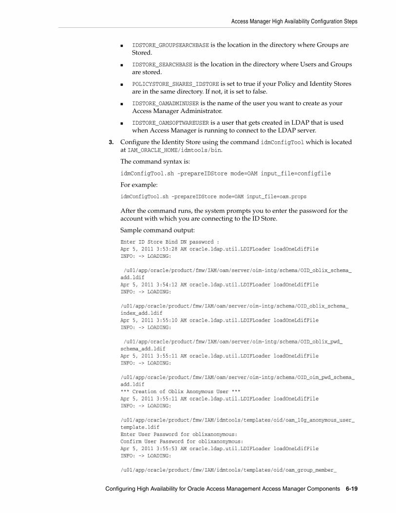
Access Manager High Availability Configuration Steps
Configuring High Availability for Oracle Access Management Access Manager Components 6-19
■ IDSTORE_GROUPSEARCHBASE is the location in the directory where Groups are Stored.
■ IDSTORE_SEARCHBASE is the location in the directory where Users and Groups are stored.
■ POLICYSTORE_SHARES_IDSTORE is set to true if your Policy and Identity Stores are in the same directory. If not, it is set to false.
■ IDSTORE_OAMADMINUSER is the name of the user you want to create as your Access Manager Administrator.
■ IDSTORE_OAMSOFTWAREUSER is a user that gets created in LDAP that is used when Access Manager is running to connect to the LDAP server.
3. Configure the Identity Store using the command idmConfigTool which is located at IAM_ORACLE_HOME/idmtools/bin.
The command syntax is:
idmConfigTool.sh -prepareIDStore mode=OAM input_file=configfile
For example:
idmConfigTool.sh -prepareIDStore mode=OAM input_file=oam.props
After the command runs, the system prompts you to enter the password for the account with which you are connecting to the ID Store.
Sample command output:
Enter ID Store Bind DN password : Apr 5, 2011 3:53:28 AM oracle.ldap.util.LDIFLoader loadOneLdifFileINFO: -> LOADING:
/u01/app/oracle/product/fmw/IAM/oam/server/oim-intg/schema/OID_oblix_schema_add.ldifApr 5, 2011 3:54:12 AM oracle.ldap.util.LDIFLoader loadOneLdifFileINFO: -> LOADING:
/u01/app/oracle/product/fmw/IAM/oam/server/oim-intg/schema/OID_oblix_schema_index_add.ldifApr 5, 2011 3:55:10 AM oracle.ldap.util.LDIFLoader loadOneLdifFileINFO: -> LOADING:
/u01/app/oracle/product/fmw/IAM/oam/server/oim-intg/schema/OID_oblix_pwd_schema_add.ldifApr 5, 2011 3:55:11 AM oracle.ldap.util.LDIFLoader loadOneLdifFileINFO: -> LOADING:
/u01/app/oracle/product/fmw/IAM/oam/server/oim-intg/schema/OID_oim_pwd_schema_add.ldif*** Creation of Oblix Anonymous User ***Apr 5, 2011 3:55:11 AM oracle.ldap.util.LDIFLoader loadOneLdifFileINFO: -> LOADING:
/u01/app/oracle/product/fmw/IAM/idmtools/templates/oid/oam_10g_anonymous_user_template.ldifEnter User Password for oblixanonymous: Confirm User Password for oblixanonymous: Apr 5, 2011 3:55:53 AM oracle.ldap.util.LDIFLoader loadOneLdifFileINFO: -> LOADING:
/u01/app/oracle/product/fmw/IAM/idmtools/templates/oid/oam_group_member_

Access Manager High Availability Configuration Steps
6-20 Oracle Fusion Middleware High Availability Guide
template.ldifThe tool has completed its operation. Details have been logged to automation.log
4. Check the log file for any errors or warnings and correct them.
See Oracle Fusion Middleware Integration Overview for Oracle Identity Management Suite for more information about the idmConfigTool command.
6.4.13.3 Create a User Identity StoreTo create a user identity store:
1. Go to the Oracle Access Management Console at the URL:
http://adminvhn.example.com:7001/oamconsole
2. Log in using the WebLogic administration user.
3. Select Configuration then Data Sources. Under the Configuration Tab, click Identity Stores.
4. Select User Identity Stores then click Add. Under OAM ID Stores, click Create. Enter the following information:
■ Store Name: LDAP_DIR
■ Store Type: OVD
■ Description: Enter a description of the Directory Store
■ Enable SSL: Select this if you communicate with your directory over SSL
■ Location: Enter the location, for example ovd.example.com:389
■ Bind DN: Enter the user permitted to search the LDAP store. For example, cn=orcladmin
■ Password: Enter the oracleadmin password
■ User Name Attribute: For example: uid
■ User Search Base: Enter the location of users in the LDAP store. For example, cn=Users,dc=example,dc=com
■ Group Name Attribute: For example: orclguid
■ Group Search Base: Enter the location of groups in the LDAP store. For example, cn=Groups,dc=example,dc=com
■ OAM Administrator Role: OAMAdministrators
5. Click Apply.
6. Click Test Connection to validate the connection to the LDAP server.
6.4.13.4 Set LDAP to System and Default StoreAfter you define the LDAP identity store, you must set it as the primary authentication store. Follow these steps in the Oracle Access Management Console:
1. Under the Configuration tab, click the System Configuration tab.
2. Select Data Sources from the navigation pane then click User Identity Stores.
3. Click LDAP_DIR.
4. Select Open from the Actions menu.

Access Manager High Availability Configuration Steps
Configuring High Availability for Oracle Access Management Access Manager Components 6-21
5. Click Set as Default Store.
6. Click Set as System Store.
7. Click the Add [+] icon in Access System Administrators.
8. Enter OAM* in the search name field and click Search.
9. Select OAMAdministrators from the search results and click Add Selected.
10. Click Apply.
11. In the Validate System Administrator window, enter the username and password of the OAM administrator, for example, oamadmin.
12. Click Validate.
13. Test the connection by clicking Test Connection.
6.4.13.5 Set Authentication to Use External LDAPBy default, Access Manager uses the integrated LDAP store for user validation. You must update the LDAP authentication module so that it can validate users against the new external LDAP store.
To update the LDAP authentication module to use external LDAP:
1. Under Application Security Tab, click the System Configuration tab.
2. Select Access Manager Settings. Click Authentication Modules and click Search.
3. Click LDAP.
4. Select Open from the Actions menu.
5. Set User Identity Store to LDAP_DIR.
6. Click Apply.
7. Restart the Managed Servers Admin Server, WLS_OAM1 and WLS_OAM2.
6.4.14 Validating the Access Manager ConfigurationValidate the configuration by logging into the Oracle Access Management Console at http://oamhost1.example.com:7001/oamconsole as oamadmin.
6.4.15 Configuring Oracle Coherence to Keep Configuration Files in SyncIn a highly available environment, Oracle Coherence keeps configuration files in sync. Oracle Coherence uses port 9095 by default but you can change this in Oracle Access Management Console.
Log in to the console at http://admin.example.com/oamconsole then follow these steps:
1. Click on the Configuration tab.
2. Click Servers then Search.
3. Double-click on the Managed Server whose port you wish to change.
4. Click on the Coherence tab.
Note: If you use oamadmin to manage OIF, you must add the OAM Administrator Role. For more information, see Section 6.4.13.3, "Create a User Identity Store."

Access Manager High Availability Configuration Steps
6-22 Oracle Fusion Middleware High Availability Guide
5. Change the value of Local Port to the desired value.
6. Click Apply.
7. Restart the Administration Server and all the managed servers residing in the same cluster as the managed server that has been updated.
6.4.16 Scaling Up Access Manager TopologyYou scale up to add a new Access Manager managed server ed to a node already running one or more server instances.
This section includes the following topics:
■ Section 6.4.16.1, "Scaling Up Access Manager"
■ Section 6.4.16.2, "Registering the New Managed Server"
■ Section 6.4.16.3, "Configuring WebGate with the New OAM Managed Server"
6.4.16.1 Scaling Up Access ManagerTo scale up OAM:
1. Log in to the Administration Console at http://hostname.example.com:7001/console. From the Domain Structure window, expand the Environment node and then Servers.
2. In the Change Center, click Lock & Edit.
3. Select a server on the host you want to extend, for example: WLS_OAM1.
4. Click Clone.
5. Enter the following information:
■ Server Name: A new name for the server, for example: WLS_OAM3.
■ Server Listen Address: The name of the host on which the managed server will run.
■ Server Listen Port: The port the new managed server will use, this port must be unique within the host.
6. Click OK.
7. Click on the newly created server WLS_OAM3
8. Set the SSL listen port. This should be unique on the host that the managed server will run on.
9. Click Save.
10. Disable hostname verification for the new managed server. You must do this before you start and verify the WLS_OAM3 Managed Server. You can re-enable it after you configure server certificates for the communication between the Administration Server and Node Manager in OAMHOSTn.
If the source server from which the new one was cloned had already disabled hostname verification, you do not need to take this step because the hostname verification settings propagated to the cloned server.
Note: Enable the SSL listen port 14101.

Access Manager High Availability Configuration Steps
Configuring High Availability for Oracle Access Management Access Manager Components 6-23
To disable hostname verification, set Hostname Verification to None then click Save.
11. Click Activate configuration from the Change Center menu.
6.4.16.2 Registering the New Managed ServerTo configure the new managed server as an OAM server, use the Oracle Access Management Console:
1. Log in to the Oracle Access Management Console as the oamadmin user at http://oamhost1.example.com:7001/oamconsole
2. Click the Configuration tab. Click Server Instances.
3. Select Create from the Actions menu.
4. Enter the following information:
■ Server Name: WLS_OAM3
■ Host: Host that the server will run on
■ Port: Listen port that was assigned when the managed server was created, for example, 14100
■ Proxy Server ID: AccessServerConfigProxy
■ Port: Port you want the OAM proxy to run on. This is unique for the host, for example, 5575
■ Mode: Open
5. Click Coherence tab.
Set Local Port to a unique value on the host.
Click Apply.
6. Click Apply when a prompt requests that you confirm the edit.
6.4.16.3 Configuring WebGate with the New OAM Managed ServerTo configure the WebGate with the new OAM Managed Server, take these steps:
1. Verify that Node Manager is running on the new Access Server WLS_OAM3.
2. Start the Managed Server using the Administration Console. See the "Start the Managed Server."
3. Inform WebGates about the new Managed Server. See "Inform WebGates of the New Managed Server."
Start the Managed ServerTo start the Managed Server using the Administration Console:
1. Log in to the new node WLS_OAM3.
2. Change to the directory ORACLE_BASE/OAM_DOMAIN/bin. For example:
/u01/app/oracle/admin/oam/user_projects/domains/oam_domain/bin
3. Start the Managed Server. For example, enter:
./startManagedWebLogic.sh WLS_OAM3 http://hostname:7001
4. At the prompt, enter the WebLogic username and password. Click Enter.

Access Manager High Availability Configuration Steps
6-24 Oracle Fusion Middleware High Availability Guide
5. Verify that the Managed Server is running. Check the startManagedWebLogic logs, or click Servers under Environment in the Administration Console to view the Summary page. Refresh the page to see updates.
Inform WebGates of the New Managed ServerTo inform any WebGates about the new Managed Server:
1. Log in to the Oracle Access Management Console at http://oamhost1.example.com:7001/oamconsole as the oamadmin user.
2. Click the Configuration tab.
3. From Launch Pad, under Application Management, click and open Agents under the Application Security tab. Click Search.
4. Click the WebGate you want to change.
5. Add the new server to either the primary or secondary server list by clicking the Add + icon.
6. Select the server name from the list.
7. Click Apply
6.4.17 Scaling Out Access ManagerYou scale out to add a new Access Manager managed server to a new node. Scale out is very similar to scale up, but requires the software to be installed on the new node.
1. Install Oracle WebLogic Server on the new host. See Section 6.4.3, "Installing Oracle WebLogic Server."
2. Install Identity Management components on the new host. See Section 6.4.4, "Installing and Configuring the Access Manager Application Tier."
3. Log in to the Administration Console at http://hostname.example.com:7001/oamconsole.
4. From the Domain Structure window of the Administration Console, expand the Environment node and then Machines.
5. From the Machines table, click New.
6. At the Create a New Machine screen labeled Machine Identity, enter the following information:
■ Name: New node host name, for example, host.example.com
■ Machine OS: Select operating system, for example, UNIX
7. Click Next.
8. In the Create New Machine screen labeled Node Manager Properties, enter this information
■ Type: Keep the default SSL
■ Listen Address: Replace localhost with the hostname that WLS_OAM3 will run on.
■ Port: Verify that the Listen Port matches the Node Manager port that will run on the other node, for example, WLS_OAM3.
9. Click Finish.
10. From the Domain Structure expand Servers.

Access Manager High Availability Configuration Steps
Configuring High Availability for Oracle Access Management Access Manager Components 6-25
11. Select a server on the host you want to extend, for example: WLS_OAM1.
12. Click Clone.
13. From the Clone a Server screen labeled Server Identity enter the following:
■ Server Name: New name for the server, for example WLS_OAM3.
■ Server Listen Address: Name of the host the Managed Server will run on.
■ Server Listen Port: Port the new managed server will use. This port must be unique within the host.
14. Click OK.
15. From the Servers table, click the new clone you just created, for example WLS_OAM3.
16. From the Machine option, assign the server to the new machine name you just created. This is the machine that the Managed Server will run on.
17. Click Save.
18. Click on the SSL tab.
19. Click Advanced.
20. Set Hostname Verification to None.
21. Click Save.
6.4.17.1 Registering the Managed Server with OAMTo register the new managed server as an OAM server:
1. Log in to the Oracle Access Management Console at http://oamhost1.example.com:7001/oamconsole as the oamadmin user.
2. Click the Configuration tab. Click Server Instances.
3. Select Create from the Actions menu.
4. Enter the following information:
■ Server Name: Enter the same server name you entered while cloning the OAM server node in the WebLogic Console.
■ Host: Host that the server will run on, OAMHOST3.
■ Port: Listen port that was assigned when you created the managed server.
■ OAM Proxy Port: Port you want the OAM proxy to run on. This is unique for the host.
■ Proxy Server ID: AccessServerConfigProxy
■ Mode: Select the appropriate mode: Open, Simple, or Cert.
5. Click Apply.
6.4.17.2 Configuring WebGate with the New OAM Access ServerStart the Access Server. To use the server, you must inform any WebGates of its existence:
1. Log in to the Oracle Access Management Console at http://oamhost1.example.com:7001/oamconsole as the oamadmin user.
2. From Launch Pad, select the Application Security tab.
3. Click Agents and click Search.

Access Manager High Availability Configuration Steps
6-26 Oracle Fusion Middleware High Availability Guide
4. Click the WebGate you want to change.
5. Under the Server Lists section, add the new OAM Access Server WLS_OAM3 to either the primary or secondary server list by clicking the Add [+] icon.
6. Select the server name from the list.
7. Click Apply.
Verifying the WebGate Configuration is UpdatedTo verify the WebGate configuration
1. Log into the Web server where the WebGate was updated previously.
2. Go to the directory WEB_HOME/config/OHS/ohs1/webgate/config
3. Open ObAccessClient.xml with a text editor. Verify that primary_server_list or secondary_server_list shows that the new OAM Access Server is updated.
Editing Oracle HTTP Server Configuration FileNow that you created and started the new Managed Server, the web tier starts to direct requests to it. However, Oracle recommends informing the web server about the new Managed Server.
To do this, update the file OAM.conf on each of the web tiers. This file resides in the directory: ORACLE_INSTANCE/config/OHS/component name/moduleconf.
Add the new server to the WebLogicCluster directive in the file. For example, change:
<Location /OAM_admin> SetHandler weblogic-handler WebLogicCluster OAMhost1.example.com:14200,OAMhost2.example.com:14200</Location>
to:
<Location /OAM_admin> SetHandler weblogic-handler WebLogicClusterOAMhost1.example.com:14200,OAMhost2.example.com:14200,OAMhost3.example.com:14300</Location>
Note: If the WebGate configuration does not update, recycle the web server, which pulls Webgate Agent profile updates to the ObAccessClient.xml file.

7
Configuring High Availability for Oracle Adaptive Access Manager Components 7-1
7Configuring High Availability for OracleAdaptive Access Manager Components
This chapter introduces Oracle Adaptive Access Manager and describes how to design and deploy a high availability environment for it.
Oracle Adaptive Access Manager is built on a J2EE-based, multi-tier deployment architecture that separates the platform's presentation, business logic, and data tiers. Because of this separation of tiers, Oracle Adaptive Access Manager can rapidly scale with the performance needs of the customer. The architecture can leverage the most flexible and supported cross-platform J2EE services available: a combination of Java, XML and object technologies. This architecture makes Oracle Adaptive Access Manager a scalable, fault-tolerant solution.
This chapter includes the following topics:
■ Section 7.1, "Oracle Adaptive Access Manager Component Architecture"
■ Section 7.2, "Oracle Adaptive Access Manager High Availability Concepts"
■ Section 7.3, "Oracle Adaptive Access Manager High Availability Configuration Steps"
7.1 Oracle Adaptive Access Manager Component ArchitectureFigure 7–1 shows the single instance architecture for Oracle Adaptive Access Manager.

Oracle Adaptive Access Manager Component Architecture
7-2 Oracle Fusion Middleware High Availability Guide
Figure 7–1 Oracle Adaptive Access Manager Single Instance Architecture
In the Oracle Adaptive Access Manager single instance architecture, end users access customer web applications, which communicate with the OAAM Server application and its policies using SOAP. Alternately, an OAAM proxy can be set up so that end users communicate with that machine, which then communicates with the OAAM_Server application using HTTP(S). Authorized end users can access the customer web application. The OAAM_ADMIN component is used for administration and configuration of the OAAM_SERVER application. The administrator responsible for administering and configuring the OAAM_Server application uses a web browser to access the OAAM_ADMIN application. An Oracle RAC database holds policy and configuration information.
End Users End Users
Firewall Firewall
RAC Database
HTTP / HTTPS
HTTP / HTTPS
HTTP / HTTPS
Customer Web Application
(OAAM Java / .NET API
Integration)
Customer Web Application
(OAAM Java / .NET API
Integration)
SOAP
OAAM_SERVER
Customer Web Application
OAAM_ADMIN
OAAM PROXY
Admin UI
HTTP / HTTPS
HTTP / HTTPS
HTTP / HTTPS
HTTP / HTTPS
HTTP / HTTPS
HTTP / HTTPS
HTTP / HTTPS

Oracle Adaptive Access Manager Component Architecture
Configuring High Availability for Oracle Adaptive Access Manager Components 7-3
7.1.1 Oracle Adaptive Access Manager Component CharacteristicsOracle Adaptive Access Manager consists of the following two components:
■ OAAM_ADMIN: This component is used for administration and configuration of OAAM_SERVER application. This component is developed using the Oracle JAVA ADF Framework the Identity Management shell and deployed as Web applications in a J2EE container. It is packaged as an EAR file.
■ OAAM_SERVER: This component contains the OAAM Admin and OAAM Server sub-components within a single web application. The OAAM_SERVER component is packaged as an EAR file and is composed of Servlets and JSPs in addition to Java classes. The subcomponents of OAAM_SERVER are described below by layer:
– Presentation Layer: typically a Web application serving JSPs, servlets, and so on. The presentation layer provides the strong authenticator functionality; it uses the interfaces provided by the business layer (SOAP or Java native) to access its services.
– Business Logic Layer: contains the core application logic that implements the risk analyzing engine. This layer provides Java and SOAP interfaces for the presentation layer. When the Java interface is used, the business logic layer and presentation layer can be part of a single web application. With the SOAP interface, these layers are deployed as different applications.
– Data Access Layer: contains data access components to connect to the supported relational databases. Oracle Adaptive Access Manager uses Oracle's TopLink, which provides a powerful and flexible framework for storing Java objects in a relational database.
■ OAAM_OFFLINE: This component is a standalone application. OAAM Offline has its own database. This database has an identical schema to that of the OAAM Online version. It is used to load customer data to perform risk analysis and tune rules. OAAM Offline can support both login and transaction data.
You can also use the following components in an Oracle Adaptive Access Manager 11g deployment:
■ Fusion Middleware Control / Enterprise Manager Grid Control: Oracle Adaptive Access Manager integrates with the Enterprise Manager Grid Control to display performance metrics and deployment topology. Oracle Adaptive Access Manager uses DMS and Discovery Mbeans to integrate with Enterprise Manager. Enterprise Manager is also used to enhance component tracing and configure auditing.
Enterprise Manager can also be used to view log files for each Managed Server in the domain and increase the tracing to Debug, Trace, and Info levels.
■ Data repositories: Oracle Adaptive Access Manager uses the RDBMS database as its data store. Oracle Adaptive Access Manager supports and works on the following database technologies:
– Oracle Real Application Clusters
– Oracle Data Guard
– Replication Streams
– Database Partitioning
Oracle Adaptive Access Manager uses RCU to creates its schema in the database.

Oracle Adaptive Access Manager Component Architecture
7-4 Oracle Fusion Middleware High Availability Guide
7.1.1.1 Oracle Adaptive Access Manager State InformationThe OAAM_Server component includes the OAAM Server subcomponent and the OAAM Admin subcomponent.
■ OAAM Server is a stateful application that stores the state in HTTP session.
■ OAAM Admin is a stateful application that stores its session information in the database.
The OAAM_Admin component is an ADF and Identity Management UI shell-based application. It is a stateless application, and its application state is maintained by the ADF framework.
The OAAM_OFFLINE component is a stateful application that stores the state in HTTP session.
7.1.1.2 Oracle Adaptive Access Manager Runtime ProcessesYou can perform the following runtime tasks using the Oracle Adaptive Access Manager Administration Console:
■ Customer Care application tasks
■ System configuration tasks involving policies, groups, and properties
■ Viewing session data information
■ Viewing the System Statistics dashboard
For example, you can perform the following administration flows:
1. Recent user query:
a. View recent logins and session details.
b. Perform a query.
c. Click Session Details.
d. Log out.
2. Manual CSR and Agent Case creation:
a. To reset customer care, log in.
b. Create a case.
c. Reset the customer.
d. Log out.
You can also perform runtime processing with the Oracle Adaptive Access Manager Server.
7.1.1.3 Oracle Adaptive Access Manager Process LifecycleThe following runtime processing occurs with Oracle Adaptive Access Manager Server:
1. Oracle Adaptive Access Manager is deployed and integrated with the customer's application.
2. The user will access the customer's application and enter user credentials.
3. Based on the system and rules configured in OAAM, different login flows will be presented, for example:
User Registration: Registration Flows

Oracle Adaptive Access Manager Component Architecture
Configuring High Availability for Oracle Adaptive Access Manager Components 7-5
a. Flow R1: Login (New User), enter password, personalize device, skip Questions Registration, log out.
b. Flow R2: Login, enter password, skip Registration, log out.
c. Flow R3: Login, enter password, personalize device, continue Questions Registration, log out.
d. Flow R4: Login, enter password, personalize device, continue Questions Registration, enter invalid answers, validation, log out
e. Flow R5: Login (New Device and New User), enter password, personalize device, continue Questions Registration, log out.
Login Flow:
a. Flow L1: Login, enter wrong password, Login screen.
b. Flow L2: Login, enter correct password, Challenge On may be presented, answer correctly, logged in.
c. Flow L3: Login, enter correct password, Challenge On presented, answer incorrectly, Challenge On presented again, answer correctly, logged in.
d. Flow L4: Login, enter correct password, Challenge On presented, answer incorrectly, Challenge On presented again, answer incorrectly, Challenge On presented again, answer correctly, logged in.
e. Flow L5: Login, enter correct password, Challenge On presented, answer incorrectly, Challenge On presented again, answer incorrectly, login blocked.
f. Flow L6: Login, enter correct password, login blocked (login screen).
g. Flow L7: Login, enter correct password, logged in.
h. Flow LNU1Login as a new user: Login, enter correct password, logged in.
i. Flow LND1: Existing user, login with a new device, enter correct password, logged in.
j. Flow LNUD1: New user, login with a new device, enter correct password, logged in.
In Session Transaction Flow: Login, enter password, create transaction, update transaction, log out.
4. OAAM tracks and registers the following data elements:
a. User login
b. User names
c. Devices (cookies, browser headers, and flash data supplied)
d. IP addresses
e. Transaction data
5. OAAM will trigger the appropriate policy based on login behavior.
As J2EE applications, you can start the Oracle Adaptive Access Manager Server and Administration Console using the WebLogic Server user interface and command line tools.
The Oracle Adaptive Access Manager Server supports a health check request (a ping request over HTTP) that can be used by a load balancer for death detection.

Oracle Adaptive Access Manager High Availability Concepts
7-6 Oracle Fusion Middleware High Availability Guide
Oracle Adaptive Access Manager is instrumented for server side metrics (using DMS) and this information is published to the Administration Console. When DMS metrics collection is enabled, monitoring the agent and server component metrics can serve as a proxy for component monitoring. In addition, Oracle Adaptive Access Manager supports fine-grained real time activity tracing, which can also serve as a proxy for component monitoring.
7.1.1.4 Oracle Adaptive Access Manager Configuration ArtifactsOracle Adaptive Access Manager stores its configuration information in the database. To change these configuration properties, use the Oracle Adaptive Access Manager Administration Console.
Oracle Adaptive Access Manager does not store any configuration information on the file system or in the exploded EAR file.
7.1.1.5 Oracle Adaptive Access Manager Deployment ArtifactsOracle Adaptive Access Manager supports the no-stage mode of deployment staging. That is, all deployment files are local.
7.1.1.6 Oracle Adaptive Access Manager External DependenciesOracle Adaptive Access Manager has an external dependency on the RDBMS database, where it stores its configuration information.
Oracle Adaptive Access Manager uses WebLogic Server multi data sources and Gridlink data source for Oracle RAC databases.
Oracle Adaptive Access Manager uses the standard Oracle TopLink object caching mechanism.
Oracle Adaptive Access Manager follows standard session object serialization to maintain the persistent state of an object.
Oracle Adaptive Access Manager is not dependent on any hostname, IP address, or port. It will work on a container-specific port or hostname.
7.1.1.7 Oracle Adaptive Access Manager Log File LocationOracle Adaptive Access Manager is a J2EE application deployed on WebLogic Server. All log messages are logged in the server log file of the WebLogic Server that the application is deployed on. The default location of the server log is:
WL_HOME/user_projects/domains/domainName/servers/serverName/logs/serverName-diagnostic.log
7.2 Oracle Adaptive Access Manager High Availability ConceptsThis section provides conceptual information about using Oracle Adaptive Access Manager in a high availability two-node cluster.
7.2.1 Oracle Adaptive Access Manager High Availability ArchitectureFigure 7–2 shows the Oracle Adaptive Access Manager high availability architecture:

Oracle Adaptive Access Manager High Availability Concepts
Configuring High Availability for Oracle Adaptive Access Manager Components 7-7
Figure 7–2 Oracle Adaptive Access Manager High Availability Architecture
In Figure 7–2, the load balancer receives incoming requests and routes them to WEBHOST1 or WEBHOST2 in the web tier. These hosts have Oracle HTTP Server installed. Oracle HTTP Server, using the WebLogic plugin mod_wl_ohs.conf, then forwards requests to the WebLogic managed servers on OAAMHOST1 and OAAMHOST2.
OAAMHOST1 and OAAMHOST2 contain managed servers that host the Oracle Adaptive Access Manager Server, the Oracle Adaptive Access Manager Admin, and the Oracle Adaptive Access Manager Offline applications. The managed servers are configured in a cluster which enables the Access Servers to work in an active-active manner.
The Administration Server runs on OAAMHOST1 and contains the Administration Console and the Oracle Enterprise Manager Fusion Middleware Control.
An Oracle RAC database provides high availability in the data tier.
Only one OAAM Server cluster, one OAAM Offline cluster, and one OAAM Administration cluster are supported per WebLogic Server domain. In addition, Oracle Adaptive Access Manager-related clusters cannot span WebLogic Server domains.
A single instance Oracle Adaptive Access Manager deployment satisfies the following high availability requirements:
■ Load handling
■ External connection management and monitoring

Oracle Adaptive Access Manager High Availability Concepts
7-8 Oracle Fusion Middleware High Availability Guide
■ Recovery
■ Fault containment
■ Fault diagnostics
■ Oracle Adaptive Access Manager Admin / Server offline
A multiple instance Oracle Adaptive Access Manager deployment satisfies the following additional high availability requirements:
■ Redundancy
■ Client connection failover / continuity
■ Client load balancing
■ State management
Oracle recommends using an external load balancing router for inbound HTTP connections.
Web sessions open persistent TCP connections to the Oracle Adaptive Access Manager Administration Console and servers. This requires that load balancing router and firewall connection timeouts are sufficiently large to avoid premature termination of TCP connections.
7.2.1.1 Starting and Stopping the ClusterEach Oracle Adaptive Access Manager Administration Console and Server instance is a peer of other instances. Because all initialization happens before the Server is ready to receive requests and because of built in throttling capabilities, surge conditions are dealt with gracefully without any significant impact of the performance characteristics of the Oracle Adaptive Access Manager 11gR2 Access Server.
When the cluster stop, new requests are denied and existing requests can complete before the Oracle Adaptive Access Manager Administration Console and Server application shuts down. If a forced shutdown occurs, Oracle Adaptive Access Manager 11gR1 recovers any corrupted or invalid data that the shutdown causes.
Oracle Adaptive Access Manager components are pure J2EE applications and do not have any start or stop functionality of their own. Instead, they rely on container-specific startup and shutdown functionality.
Oracle Adaptive Access Manager components deploy to WebLogic Server Managed Server nodes. You restart the components using Node Manager.
7.2.1.2 Cluster-Wide Configuration ChangesSince Oracle Adaptive Access Manager stores the entire configuration in database, the propagation of configuration changes to all the cluster members transparent. All Oracle Adaptive Access Manager components are notified of change events from the internal layer, which are then taken up by the components. To ensure atomicity of the change, Oracle Adaptive Access Manager components reload their entire configuration every time a change happens.
Oracle Adaptive Access Manager configuration applies to every instance in a cluster.
Adding and removing Oracle Adaptive Access Manager Administration Console and Server instances is transparent to other Oracle Adaptive Access Manager instances in the cluster.
An Oracle Adaptive Access Manager cluster can have any number of instances. There is no restriction on the number of instances per cluster.

Oracle Adaptive Access Manager High Availability Configuration Steps
Configuring High Availability for Oracle Adaptive Access Manager Components 7-9
Online application redeployment does not cause any problems.
7.2.2 Protection from Failures and Expected BehaviorsThe following features protect an Oracle Adaptive Access Manager high availability configuration from failure:
■ Session state for the cluster is maintained in memory, which provides replication and failover for all session state information.
■ Oracle Adaptive Access Manager Servers support a heartbeat check - a ping request over HTTP. In addition, the WebLogic Node Manager on the Managed Server can monitor the application and restart it if it is not running. Restarting an Oracle Adaptive Access Manager Server has no impact on any other running components or cluster members.
■ When a WebLogic Server node fails, external connection failover is based on the configuration and is based on the retry timeout as well as the number of retries.
■ When the load balancing router or proxy server detects a WebLogic Server node failure, subsequent client connections are routed to the active instance, which picks up the session state for further processing.
■ An Oracle Adaptive Access Manager session does not have a direct impact on an Oracle RAC database node failure, because WebLogic Server maintains the state of its database connections.
7.3 Oracle Adaptive Access Manager High Availability Configuration Steps
This section provides high-level instructions for setting up a maximum high availability deployment for Oracle Adaptive Access Manager. This deployment includes two Oracle HTTP Servers, which distribute requests to two OAAM servers. These OAAM servers interact with an Oracle Real Application Clusters (Oracle RAC) database. If any single component fails, then the remaining components will continue to function.
This section includes the following topics:
■ Section 7.3.1, "Prerequisites for Oracle Adaptive Access Manager Configuration"
■ Section 7.3.2, "Run the Repository Creation Utility to Create the OAAM Schemas in a Database"
■ Section 7.3.3, "Installing Oracle WebLogic Server"
■ Section 7.3.4, "Installing and Configuring the Oracle Adaptive Access Manager Application Tier"
■ Section 7.3.5, "Configuring the Database Security Store for the Domain"
■ Section 7.3.6, "Creating boot.properties for the Administration Server on OAAMHOST1"
■ Section 7.3.7, "Create the Oracle Adaptive Access Manager Administration User"
■ Section 7.3.8, "Start OAAMHOST1"
■ Section 7.3.9, "Validating OAAMHOST1"
■ Section 7.3.10, "Configure Oracle Adaptive Access Manager on OAAMHOST2"
■ Section 7.3.11, "Start OAAMHOST2"

Oracle Adaptive Access Manager High Availability Configuration Steps
7-10 Oracle Fusion Middleware High Availability Guide
■ Section 7.3.12, "Validating OAAMHOST2"
■ Section 7.3.13, "Configure Oracle Adaptive Access Manager to Work with Oracle HTTP Server"
■ Section 7.3.14, "Validating the Oracle Adaptive Access Manager Configuration"
■ Section 7.3.15, "Scaling Up and Scaling Out the Oracle Adaptive Access Manager Topology"
7.3.1 Prerequisites for Oracle Adaptive Access Manager ConfigurationBefore you configure Oracle Adaptive Access Manager for high availability, you must:
■ Run the Repository Creation Utility to create the OAAM schemas in a database. See Section 7.3.2, "Run the Repository Creation Utility to Create the OAAM Schemas in a Database".
■ Install Oracle WebLogic Server on OAAMHOST1 and OAAMHOST2. See Section 7.3.3, "Installing Oracle WebLogic Server"
■ Install and configure the Oracle Identity Management executables on OAAMHOST1 and OAAMHOST2. See Follow the steps in Section 7.3.4, "Installing and Configuring the Oracle Adaptive Access Manager Application Tier".
7.3.2 Run the Repository Creation Utility to Create the OAAM Schemas in a DatabaseThe schemas you create depend on the products you want to install and configure. Use the Repository Creation Utility (RCU) that is version compatible with the product you are installing. See the Oracle Fusion Middleware Installation Planning Guide for Oracle Identity and Access Management and Oracle Fusion Middleware Repository Creation Utility User's Guide to run RCU.
7.3.3 Installing Oracle WebLogic ServerBefore you install the Oracle WebLogic Server, ensure that your machines meet the system, patch, kernel, and other requirements as specified in Oracle Fusion Middleware Installation Guide for Oracle WebLogic Server.
To install Oracle WebLogic Server on OAAMHOST1 and OAAMHOST2, start the installer then complete these steps:
1. On the Welcome screen, click Next.
2. On the Choose Middleware Home Directory screen, select Create a New Middleware Home.
For Middleware Home Directory, enter:
ORACLE_BASE/product/fmw
Click Next.
3. On the Register for Security Updates screen, enter your contact information so that you can be notified of security updates.
Click Next.
Note: ORACLE_BASE is the base directory under which Oracle products are installed. The recommended value is /u01/app/oracle.

Oracle Adaptive Access Manager High Availability Configuration Steps
Configuring High Availability for Oracle Adaptive Access Manager Components 7-11
4. On the Choose Install Type screen, select Custom.
Click Next.
5. On the Choose Products and Components screen, select the JRE/JDK and click Next.
6. On the Choose Product Installation Directories screen, accept the directory ORACLE_BASE/product/fmw/wlserver_10.3.
Click Next.
7. On the Installation Summary screen, click Next.
8. On the Installation Complete screen, deselect Run Quickstart.
Click Done.
7.3.4 Installing and Configuring the Oracle Adaptive Access Manager Application TierThis section describes how to install Oracle Fusion Middleware components on OAAMHOST1 and OAAMHOST2.
7.3.4.1 Install Oracle Fusion Middleware for Identity ManagementPerform these steps to install Oracle Fusion Middleware components on OAAMHOST1 and OAAMHOST2.
If the /etc/oraInst.loc file exists, verify that its contents are correct. Specifically, check that the inventory directory is correct and that you have write permissions for that directory. If the /etc/oraInst.loc file does not exist, you can skip this step.
Start the installer for Oracle Fusion Middleware as follows:
OAAMHOST1> runInstaller
When the installer prompts you for a JRE/JDK location, enter the Oracle SDK location created in the WebLogic Server installation, for example, ORACLE_BASE/product/fmw/JRE_JDK_version then proceed as follows:
1. On the Welcome screen, click Next.
2. On the Prerequisite Checks screen, verify that the checks complete successfully, then click Next.
3. On the Specify Installation Location screen, enter the following values:
■ Oracle Middleware Home: Select the previously installed Middleware home from the list for MW_HOME for example:
/u01/app/oracle/product/fmw
■ Oracle Home Directory:
– Enter iam as the Oracle Home directory name when installing the Oracle Identity and Access Management Suite in the IAM_ORACLE_HOME.
Click Next.
4. On the Installation Summary screen, click Install.
5. On the Installation Complete screen, click Finish.
7.3.4.1.1 Configure Oracle Access Manager on OAAMHOST1 This section creates the domain on OAAMHOST1.

Oracle Adaptive Access Manager High Availability Configuration Steps
7-12 Oracle Fusion Middleware High Availability Guide
Start the configuration wizard by running the command:
ORACLE_HOME/oracle_common/common/bin/config.sh
Then continue with the following steps:
1. In the Welcome screen, select Create a New WebLogic Domain then click Next.
2. In the Select Domain Source Screen:
Select Generate a domain configured automatically to support the following products:
And select the following products:
■ Oracle Enterprise Manager
■ Oracle JRF (selected by default)
■ Oracle Adaptive Access Manager - Server
■ Oracle Adaptive Access Manager Admin Server
Click Next.
3. In the Specify Domain and Location screen enter:
■ Domain name: IDM_Domain
■ Domain Directory: Accept the default.
■ Application Directory: Accept the default.
Click Next.
4. In the Configure Administrator Username and Password screen, enter the username and password to be used for the domain's administrator and click Next.
5. In the Configure Server Start Mode and JDK screen, make the following selections:
■ WebLogic Domain Startup Mode: Select Production Mode.
■ JDK Selection: Select the JRE/JDK.
6. In the Configure JDBC Component Schema screen, select all of the data sources, then select Configure selected data sources as RAC multi data sources.
Click Next.
7. In the Configure RAC Multi Data Source Component Schema screen, select the first data source, OAAM Admin Server, and enter the following:
■ Data source: OAAM Admin Server
■ Service Name: oaam.example.com
■ User Name: OAAM_OAAM (assuming OAAM was used as the RCU prefix)
■ Password: The password for above account
In the top right box, click Add to add an Oracle RAC host. Enter the following information:
■ Host Name: OAAMDBHOST1
■ Instance Name: oaamdb1
■ Port: 1521
Click Add again to add the second database host and enter the following information:

Oracle Adaptive Access Manager High Availability Configuration Steps
Configuring High Availability for Oracle Adaptive Access Manager Components 7-13
■ Host Name: OAAMDBHOST2
■ Instance Name: oaamdb2
■ Port: 1521
Deselect this data source. Select the next data source, OAAM Admin MDS Schema, and enter the following information:
■ Data Source: OAAM Admin MDS Schema
■ Service Name: oaam.example.com
■ User Name: OAAM_MDS (assuming OAAM was used as the RCU prefix)
■ Password: Password for the OAAM_MDS account.
In the top right box, click Add to add an Oracle RAC host. Enter the following information:
■ Host Name: OAAMDBHOST1
■ Instance Name: oaamdb1
■ Port: 1521
Click Add again to add the second database host and enter the following information:
■ Host Name: OAAMDBHOST2
■ Instance Name: oaamdb2
■ Port: 1521
Deselect this data source. Select the next data source, OAAM Server, and enter the following information:
■ Data Source: OAAM Server
■ Service Name: oaam.example.com
■ User Name: OAAM_OAAM (assuming OAAM was used as the RCU prefix)
■ Password: Password for the OAAM_OAAM account.
In the top right box, click Add to add an Oracle RAC host. Enter the following information:
■ Host Name: OAAMDBHOST1
■ Instance Name: oaamdb1
■ Port: 1521
Click Add again to add the second database host and enter the following information:
■ Host Name: OAAMDBHOST2
■ Instance Name: oaamdb2
■ Port: 1521
Deselect this data source. Select the next data source, OWSM MDS Schema, and enter the following information:
■ Data Source: OWSM MDS Schema
■ Service Name: oaam.example.com

Oracle Adaptive Access Manager High Availability Configuration Steps
7-14 Oracle Fusion Middleware High Availability Guide
■ User Name: OAAM_MDS (assuming OAAM was used as the RCU prefix)
■ Password: Password for the OAAM_MDS account.
In the top right box, click Add to add an Oracle RAC host. Enter the following information:
■ Host Name: INFRADBHOST1
■ Instance Name: oaamdb1
■ Port: 1521
Click Add again to add the second database host and enter the following information:
■ Host Name: INFRADBHOST2
■ Instance Name: oaamdb2
■ Port: 1521
Deselect this data source.
Click Next.
8. In the Test Component Schema screen, the configuration wizard attempts to validate the data source.
If the data source validation succeeds, click Next.
If it fails, click Previous, correct the issue, and try again.
9. In the Select Optional Configuration screen, select:
■ Administration Server
■ Managed Server Clusters and Machines
Click Next.
10. In the Customize Server and Cluster Configuration screen, select Yes, and click Next.
11. In the Configure the Administration Server screen, enter the following values:
■ Name: AdminServer
■ Listen Address: Enter the virtual hostname of the Administration Server, for example: OAAMHOST1.example.com
■ Listen Port: 7001
■ SSL listen port: Not applicable
■ SSL enabled: leave unchecked
Click Next.
12. On the Configure Managed Servers screen, create three entries for each OAAMHOST in the topology: one for OAAM Server, OAAM Admin Server, and OAAM Offline server.
Select the OAAM_SERVER entry and change the entry to the following values:
■ Name: WLS_OAAM1_SERVER1
■ Listen Address: OAAMHOST1.example.com
■ Listen Port: 14300

Oracle Adaptive Access Manager High Availability Configuration Steps
Configuring High Availability for Oracle Adaptive Access Manager Components 7-15
■ SSL Listen Port: 14301
■ SSL Enabled: Selected
For the second OAAM_SERVER, click Add and supply the following information:
■ Name: WLS_OAAM2_SERVER2
■ Listen Address: OAAMHOST2.example.com
■ Listen Port: 14300
■ SSL Listen Port: 14301
■ SSL Enabled: Selected
Select the OAAM Offline entry and change the entry to the following values:
■ Name: WLS_OAAM_OFFLINE1
■ Listen Address: OAAMHOST1.example.com
■ Listen Port: 14400
■ SSL Listen Port: 14401
■ SSL Enabled: Selected
For the second OAAM Offline, click Add and supply the following information:
■ Name: WLS_OAAM_OFFLINE2
■ Listen Address: OAAMHOST2.example.com
■ Listen Port: 14400
■ SSL Listen Port: 14401
■ SSL Enabled: Selected
Select the OAAM_ADMIN_SERVER entry and change the entry to the following values:
■ Name: WLS_OAAM_ADMIN1
■ Listen Address: OAAMHOST1.example.com
■ Listen Port: 14200
■ SSL Listen Port: 14201
■ SSL Enabled: Selected
For the second OAAM_ADMIN_SERVER, click Add and supply the following information:
■ Name: WLS_OAAM_ADMIN2
■ Listen Address: OAAMHOST2.example.com
■ Listen Port: 14200
■ SSL Listen Port: 14201
■ SSL Enabled: Selected
Leave all other fields at the default settings.
Click Next.
13. In the Configure Clusters screen, create a cluster by clicking Add.
Enter name: OAAM_SERVER_CLUSTER

Oracle Adaptive Access Manager High Availability Configuration Steps
7-16 Oracle Fusion Middleware High Availability Guide
Create a second cluster by clicking Add.
Enter name: OAAM_Offline_Cluster
Create a third cluster by clicking Add.
Enter name: OAAM_Admin_Cluster
Leave all other fields at the default settings.
Click Next.
14. On the Assign Servers to Clusters screen, associate the managed servers with the cluster, as follows:
■ Click the cluster name OAAM_SERVER_CLUSTER in the right window.
■ Click the managed server WLS_OAAM1_SERVER1, then click the arrow to assign it to the cluster.
■ Repeat for managed server WLS_OAAM2_SERVER2.
Then:
■ Click the cluster name OAAM_OFFLINE_Cluster in the right window.
■ Click the managed server WLS_OAAM_OFFLINE1, then click the arrow to assign it to the cluster.
■ Repeat for managed server WLS_OAAM_OFFLINE2.
Then:
■ Click the cluster name OAAM_Admin_Cluster in the right window.
■ Click the managed server WLS_OAAM_ADMIN1, then click the arrow to assign it to the cluster.
■ Repeat for managed server WLS_OAAM_ADMIN2.
Click Next.
15. On the Configure Machines screen, create a machine for each host in the topology. Click the UNIX tab if your hosts use a UNIX-based operating system. Otherwise, click the Machines tab. Supply the following information:
■ Name: Name of the host. The best practice is to use the DNS name (OAAMHOST1)
■ Node Manager Listen Address: The DNS name of the machine (OAAMHOST1.example.com)
■ Node Manager Port: A port for Node Manager to use.
Click Next.
16. In the Assign Servers to Machines screen, indicate which managed servers will run on the machines just created.
For OAAMHOST1:
■ Click the machine OAAMHOST1 in the right window.
■ Click the managed server WLS_OAAM1_SERVER1 in the left window.
■ Click the arrow to assign the managed server to the host OAAMHOST1.
■ Click the managed server WLS_OAAM_OFFLINE1 in the left window.
■ Click the arrow to assign the managed server to the host OAAMHOST1.

Oracle Adaptive Access Manager High Availability Configuration Steps
Configuring High Availability for Oracle Adaptive Access Manager Components 7-17
■ Click the managed server WLS_OAAM_ADMIN1 in the left window.
■ Click the arrow to assign the managed server to the host OAAMHOST1.
For OAAMHOST2:
■ Click the machine OAAMHOST2 in the right window.
■ Click the managed server WLS_OAAM2_SERVER2 in the left window.
■ Click the arrow to assign the managed server to the host OAAMHOST2.
■ Click the managed server WLS_OAAM_OFFLINE2 in the left window.
■ Click the arrow to assign the managed server to the host OAAMHOST2.
■ Click the managed server WLS_OAAM_ADMIN2 in the left window.
■ Click the arrow to assign the managed server to the host OAAMHOST2.
Click Next.
17. On the Configuration Summary screen, click Create to begin the creation process.
7.3.5 Configuring the Database Security Store for the DomainYou must configure the database security store after you configure the domain but before you start the Administration Server. See Section 7.3.5, "Configuring the Database Security Store for the Domain" for more information.
7.3.6 Creating boot.properties for the Administration Server on OAAMHOST1This section describes how to create a boot.properties file for the Administration Server on OAAMHOST1. The boot.properties file enables the Administration Server to start without prompting for the administrator username and password.
To create the boot.properties file:
1. Start the Admin Server.
2. On OAAMHOST1, go the following directory:
MW_HOME/user_projects/domains/domainName/servers/AdminServer/security
For example:
cd /u01/app/oracle/product/fmw/user_projects/domains/IDMDomain/servers/AdminServer/security
3. Use a text editor to create a file called boot.properties under the security directory. Enter the following lines in the file:
username=adminUserpassword=adminUserPassword
4. Stop the Administration Server if it is running.
Note: When you start the Administration Server, the username and password entries in the file get encrypted.
For security reasons, minimize the time the entries in the file are left unencrypted. After you edit the file, you should start the server as soon as possible so that the entries get encrypted.

Oracle Adaptive Access Manager High Availability Configuration Steps
7-18 Oracle Fusion Middleware High Availability Guide
See the "Starting and Stopping Oracle Fusion Middleware" chapter of the Administrator's Guide for information on starting and stopping WebLogic Servers.
5. Start the Administration Server on OAAMHOST1 using the startWebLogic.sh script located under the MW_HOME/user_projects/domains/domainName/bin directory.
6. Validate that the changes were successful by opening a web browser and accessing the following pages:
■ WebLogic Server Administration Console at:
http://oaamhost1.example.com:7001/console
■ Oracle Enterprise Manager Fusion Middleware Control at:
http://oaamhost1.example.com:7001/em
Log into these consoles using the weblogic user credentials.
7.3.7 Create the Oracle Adaptive Access Manager Administration UserTo create an Administrative user, which will be used to access the OAAM console:
1. Log into the WebLogic Administration Console using this URL:
http://oaamhost1.example.com:7001/console
2. From the Domain Structure menu, click Security Realms and then myrealm.
3. Click the Users and Groups tab.
4. Click the Users sub tab.
5. Click New.
6. Enter these values:
■ Name: Name for the user, for example: oaamadmin
■ Provider: Default Authenticator
■ Password/Confirmation: Password for user
Click OK.
7. After the user is created, click the user name.
8. Click on the Groups sub tab.
9. Assign the user to the following groups:
■ OAAMCSRGroup
■ OAAMCSRManagerGroup
■ OAAMInvestigatorGroup
■ OAAMInvestigationManagerGroup
■ OAAMRuleAdministratorGroup
■ OAAMEnvAdminGroup
■ OAAMSOAPServicesGroup
Click Save.

Oracle Adaptive Access Manager High Availability Configuration Steps
Configuring High Availability for Oracle Adaptive Access Manager Components 7-19
7.3.8 Start OAAMHOST1This section describes the steps for starting OAAMHOST1.
7.3.8.1 Create the Node Manager Properties File on OAAMHOST1Before you can start managed servers from the console, you must create a Node Manager property file. You do this by running the script setNMProps.sh, which is located in the MW_HOME/oracle_common/common/bin directory. For example:
MW_HOME/oracle_common/common/bin/setNMProps.sh
7.3.8.2 Start Node ManagerStart Node Manager by issuing the following command:
MW_HOME/wlserver_10.3/server/bin/startNodeManager.sh
7.3.8.3 Start Oracle Adaptive Access Manager on OAAMHOST1To start Oracle Adaptive Access Manager on OAAMHOST1, follow these steps:
1. Log into the WebLogic Administration Console using this URL:
http://oaamhost1.example.com:7001/console
2. Supply the WebLogic administrator username and password.
3. Select Environment - Servers from the Domain Structure menu.
4. Click the Control tab.
5. Click the servers WLS_OAAM1_SERVER1, WLS_OAAM_OFFLINE1, and WLS_OAAM_ADMIN1.
6. Click Start.
7. Click OK to confirm that you want to start the servers.
7.3.9 Validating OAAMHOST1Validate the implementation by connecting to the OAAM Administration Server at the following URL:
http://OAAMHOST1.example.com:14200/oaam_admin
The implementation is valid if the OAAM Admin console login page is displayed and you can login using the oaamadmin account you created in Section 7.3.7, "Create the Oracle Adaptive Access Manager Administration User."
Validate the implementation by connecting to the OAAM Server at:
http://OAAMHOST1.example.com:14300/oaam_server
The implementation is valid if the OAAM Server login page appears.
7.3.10 Configure Oracle Adaptive Access Manager on OAAMHOST2Once the configuration has succeeded on OAAMHOST1, you can propagate it to OAAMHOST2. You do this by packing the domain using the pack script on OAAMHOST1, and unpacking the domain using the unpack script on OAAMHOST2.

Oracle Adaptive Access Manager High Availability Configuration Steps
7-20 Oracle Fusion Middleware High Availability Guide
Both scripts reside in the MW_HOME/oracle_common/common/bin directory.
On OAAMHOST1, enter:
pack.sh -domain=$MW_HOME/user_projects/domains/IDM_Domain \ -template=/tmp/idm_domain.jar -template_name="OAAM Domain" -managed=true
This creates a file called idm_domain.jar in the /tmp directory. Copy this file to OAAMHOST2.
On OAAMHOST2, enter:
unpack.sh -domain=$MW_HOME/user_projects/domains/IDM_Domain \ -template=/tmp/idm_domain.jar
7.3.11 Start OAAMHOST2Now you will start OAAMHOST2.
This section describes the steps for starting OAAMHOST2.
7.3.11.1 Create the Node Manager Properties File on OAAMHOST2Before you can start managed servers from the console, you must create a Node Manager property file. You do this by running the script setNMProps.sh, which is located in the MW_HOME/oracle_common/common/bin directory. For example:
MW_HOME/oracle_common/common/bin/setNMProps.sh
7.3.11.2 Start Node ManagerStart Node Manager by issuing the following command:
MW_HOME/wlserver_10.3/server/bin/startNodeManager.sh
7.3.11.3 Start Oracle Adaptive Access Manager on OAAMHOST2To start Oracle Adaptive Access Manager on OAAMHOST2, follow these steps:
1. Log into the WebLogic Administration Console using this URL:
http://oaamhost2.example.com:7001/console
2. Supply the WebLogic administrator username and password.
3. Select Environment - Servers from the Domain Structure menu.
4. Click the Control tab.
5. Click the servers WLS_OAAM2_SERVER2, WLS_OAAM_OFFLINE2,and WLS_OAAM_ADMIN2.
6. Click Start.
7. Click OK to confirm that you want to start the servers.
7.3.12 Validating OAAMHOST2Validate the implementation by connecting to the OAAM Administration Server at the following URL:
http://OAAMHOST2.example.com:14200/oaam_admin

Oracle Adaptive Access Manager High Availability Configuration Steps
Configuring High Availability for Oracle Adaptive Access Manager Components 7-21
The implementation is valid if OAAM Admin console login page is displayed and you can login using the oaamadmin account you created in Section 7.3.7, "Create the Oracle Adaptive Access Manager Administration User."
Validate the implementation by connecting to the OAAM Server at:
http://OAAMHOST2.example.com:14400/oaam_server
The implementation is valid if the OAAM Server login page is displayed.
7.3.13 Configure Oracle Adaptive Access Manager to Work with Oracle HTTP ServerTo configure Oracle Adaptive Access Manager to work with Oracle HTTP Server, follow these steps:
■ Section 7.3.13.1, "Update Oracle HTTP Server Configuration"
■ Section 7.3.13.2, "Restart Oracle HTTP Server"
■ Section 7.3.13.3, "Change Host Assertion in WebLogic"
7.3.13.1 Update Oracle HTTP Server ConfigurationOn WEBHOST1 and WEBHOST2, create a file named oaam.conf in the this directory:
ORACLE_INSTANCE/config/OHS/ohs1/moduleconf
Create the file with the following lines:
NameVirtualHost *:7777<VirtualHost *:7777> ServerName oaam.example.com:7777 ServerAdmin [email protected] RewriteEngine On RewriteOptions inherit <Location /oaam_server> SetHandler weblogic-handler WebLogicCluster oaamhost1.example.com:14300,oaamhost2.example.com:14300 </Location> <Location /oaam_offline> SetHandler weblogic-handler WebLogicCluster oaamhost1.example.com:14400,oaamhost2.example.com:14400 WebLogicPort 7001 </Location> <Location /oaam_admin> SetHandler weblogic-handler WebLogicCluster oaamhost1.example.com:14200,oaamhost2.example.com:14200 WebLogicPort 7001 </Location> </VirtualHost>
7.3.13.2 Restart Oracle HTTP ServerRestart the Oracle HTTP Server on WEBHOST1 and WEBHOST2:
WEBHOST1>opmnctl stopall

Oracle Adaptive Access Manager High Availability Configuration Steps
7-22 Oracle Fusion Middleware High Availability Guide
WEBHOST1>opmnctl startall
WEBHOST2>opmnctl stopallWEBHOST2>opmnctl startall
7.3.13.3 Change Host Assertion in WebLogicBecause the Oracle HTTP Server acts as a proxy for WebLogic, by default certain CGI environment variables are not passed through to WebLogic. These include the host and port. You must tell WebLogic that it is using a virtual site name and port so that it can generate internal URLs appropriately.
To do this, log into the WebLogic Administration Console at:
http://oaamhost1.example.com:7001/console
Then perform these steps:
1. Select Clusters from the home page, or select Environment > Clusters from the Domain Structure menu.
2. Click Lock and Edit in the Change Center window to enable editing.
3. Click the Cluster Name (OAAM_SERVER_CLUSTER).
4. In the General tab, set WebLogic Plug in to Enabled by checking the box in the Advanced Properties section.
5. Click Save.
6. Select HTTP and enter the following values:
■ Frontend Host: oaam.example.com
■ Frontend HTTP Port: 7777
■ Frontend HTTPS Port: Set to SSL port on the load balancer or the Oracle HTTP Server SSL port if using SSL communication.
This ensures that HTTPS URLs created within WebLogic are directed to port 443 or 80 on the load balancer.
7. Click Save.
8. Select Clusters from the home page, or select Environment > Clusters from the Domain Structure menu.
9. Click the Cluster Name (oaam_admin_cluster).
10. In the General tab, set WebLogic Plug in to Enabled by checking the box in the Advanced Properties section.
11. Click Save.
12. Select HTTP and enter the following values:
■ Frontend Host: oaam.example.com
■ Frontend HTTP Port: 7777
■ Frontend HTTPS Port: Set to SSL port on the load balancer or the Oracle HTTP Server SSL port if using SSL communication.
13. Click Save.
14. Click Activate Changes in the Change Center window to save the changes.

Oracle Adaptive Access Manager High Availability Configuration Steps
Configuring High Availability for Oracle Adaptive Access Manager Components 7-23
15. Restart managed servers WLS_OAAM1_SERVER1, WLS_OAAM2_SERVER2, WLS_OAAM_OFFLINE1, WLS_OAAM_OFFLINE2, WLS_OAAM_ADMIN1 and WLS_OAAM_ADMIN2 as follows:
a. Log into the WebLogic Administration Console using this URL:
http://oaamhost1.example.com:7001/console
b. Supply the WebLogic administrator username and password.
c. Select Environment - Servers from the Domain Structure menu.
d. Click the Control tab.
e. Click the servers WLS_OAAM1_SERVER1, WLS_OAAM2_SERVER2, WLS_OAAM_OFFLINE1, WLS_OAAM_OFFLINE2, WLS_OAAM_ADMIN1, and WLS_OAAM_ADMIN2.
f. Click Shutdown - Force shutdown now.
g. Click Yes to confirm that you want to stop the servers.
h. Select Environment - Servers from the Domain Structure menu.
i. Click the Control tab.
j. Click the servers WLS_OAAM1_SERVER1, WLS_OAAM2_SERVER2, WLS_OAAM_OFFLINE1, WLS_OAAM_OFFLINE2, WLS_OAAM_ADMIN1, and WLS_OAAM_ADMIN2.
k. Click Start.
l. Click Yes to confirm that you want to start the servers.
16. Restart the Administration Server.
7.3.14 Validating the Oracle Adaptive Access Manager ConfigurationLog into the Oracle Adaptive Access Manager Administration Console at http://oaam.example.com:7777/oaam_admin using the oaamadmin account you created.
Log into the Oracle Adaptive Access Manager server at http://oaam.example.com:7777/oaam_offline using the oaamadmin account and the password test.
Also, log into the Oracle Adaptive Access Manager server at http://oaam.example.com:7777/oaam_server using the oaamadmin account and the password test.
Complete the steps that the 7.7 Post-Installation Steps section of the Oracle Fusion Middleware Installation Guide for Oracle Identity and Access Management describes.
7.3.15 Scaling Up and Scaling Out the Oracle Adaptive Access Manager TopologyThis section describes how to scale up and scale out an Oracle Adaptive Access Manager high availability topology. Perform a scale up operation to add a new Oracle Adaptive Access Manager managed server instance is added to a node already running one or more server instances. Perform a scale out operation to add a new Oracle Adaptive Access Manager managed server instance to a new node.

Oracle Adaptive Access Manager High Availability Configuration Steps
7-24 Oracle Fusion Middleware High Availability Guide
7.3.15.1 Scaling Up Oracle Adaptive Access ManagerTo scale up OAAM, use the same procedure for both the OAAM server and the OAAM Administration Server.
Log in to the Oracle WebLogic Server console at: http://oaamhost1.example.com:7001/console. Then proceed as follows:
1. From the Domain Structure window of the Oracle WebLogic Server Administration Console, expand the Environment node and then Servers. The Summary of Servers page appears.
2. Click Lock & Edit from the Change Center menu.
3. Select an existing server on the host that you want to extend, for example: WLS_OAAM1_SERVER1 or WLS_OAAM_ADMIN1.
4. Click Clone.
5. Enter the following information:
■ Server Name: A new name for the server, for example: WLS_OAAM3.
■ Server Listen Address: The name of the host on which the managed server will run.
■ Server Listen Port: The port the new managed server will use. This port must be unique within the host.
6. Click OK.
7. Click the newly-created server WLS_OAAM3.
8. Set the SSL listen port. This should be unique on the host that the managed server will be running on.
9. Click Save.
10. Disable hostname verification for the new managed server. Before starting and verifying the WLS_OAAM3 managed server, you must disable hostname verification. You can re-enable it after you have configured server certificates for the communication between the Oracle WebLogic Administration Server and the Node Manager in OAAMHOSTn.
If the source server from which the new one was cloned had already disabled hostname verification, these steps are not required, as the hostname verification settings were propagated to the cloned server. To disable hostname verification:
a. In the Oracle Fusion Middleware Enterprise Manager Console, select Oracle WebLogic Server Administration Console.
b. Expand the Environment node in the Domain Structure pane.
c. Click Servers. The Summary of Servers page appears.
d. Select WLS_OAAM3 in the Names column of the table. The Settings page for server appears.
e. Click the SSL tab.
f. Click Advanced.
g. Set Hostname Verification to None.
h. Click Save.
11. Click Activate configuration from the Change Center menu.

Oracle Adaptive Access Manager High Availability Configuration Steps
Configuring High Availability for Oracle Adaptive Access Manager Components 7-25
7.3.15.2 Scaling Out Oracle Adaptive Access ManagerScale out is very similar to scale up, but first requires the software to be installed on the new node. Proceed as follows:
1. Install Oracle WebLogic Server on the new host as described in Section 5.4.1.2, "Installing Oracle WebLogic Server."
2. Install Oracle Fusion Middleware Identity Management components on the new host. See Section 7.3.4, "Installing and Configuring the Oracle Adaptive Access Manager Application Tier."
3. Log in to the WebLogic console at http://oaamhost1.example.com:7001/console.
4. From the Domain Structure pane of the Administration Console, expand the Environment node and then Servers. The Summary of Servers page appears.
5. Click Lock & Edit from the Change Center menu.
6. Select an existing server on the host you want to extend, for example: WLS_OAAM1_SERVER1 or WLS_OAAM_ADMIN1.
7. Click Clone.
8. Enter the following information:
■ Server Name: A new name for the server, for example: WLS_OAAM3
■ Server Listen Address: The name of the host on which the managed server will run.
■ Server Listen Port: The port the new managed server will use. This port must be unique within the host.
9. Click OK.
10. Click the newly-created server WLS_OAAM3.
11. Set the SSL listen port. This should be unique on the host that the managed server will be running on.
12. Click Save.
13. Disable hostname verification for the new managed server. Before starting and verifying the WLS_OAAM3 managed server, you must disable hostname verification. You can re-enable it after you have configured server certificates for the communication between the Oracle WebLogic Administration Server and the Node Manager in OAAMHOSTn.
If the source server from which the new one was cloned had already disabled hostname verification, these steps are not required, as the hostname verification settings were propagated to the cloned server. To disable hostname verification:
a. In the Oracle Fusion Middleware Enterprise Manager Console, select Oracle WebLogic Server Administration Console.
b. Expand the Environment node in the Domain Structure pane.
c. Click Servers. The Summary of Servers page appears.
d. Select WLS_OAAM3 in the Names column of the table. The Settings page for server appears.
e. Click the SSL tab.
f. Click Advanced.
g. Set Hostname Verification to None.

Oracle Adaptive Access Manager High Availability Configuration Steps
7-26 Oracle Fusion Middleware High Availability Guide
h. Click Save.
14. Click Activate configuration from the Change Center menu.
15. Pack the domain on OAAMHOST1 using the command:
pack.sh -domain=ORACLE_BASE/admin/IDM_Domain/aserver/IDM_Domain -template =/tmp/idm_domain.jar -template_name="OAAM Domain" -managed=true
The pack.sh script is located in MW_HOME/oracle_common/common/bin.
16. Unpack the domain on the new host using the command:
unpack.sh -domain=ORACLE_BASE/admin/IDM_Domain/mserver/IDM_Domain -template=/tmp/idm_domain.jar -template_name="OAAM Domain" -app_dir=ORACLE_BASE/admin/IDM_Domain/mserver/applications
The unpack.sh script is located in MW_HOME/oracle_common/common/bin.
17. Before you can start managed servers from the console, you must create a node manager properties file on OAAMHOST2 by running the script setNMProps.sh. The setNMProps.sh script is located in MW_HOME/oracle_common/common/bin. Type:
MW_HOME/oracle_common/common/bin/setNMProps.sh
18. Start Node Manager and the new managed server on the new host
19. Now that the new managed server has been created and started, the web tier will start to direct requests to it. Best practice, however, is to inform the web server that the new managed server has been created.
You do this by updating the file oaam.conf on each of the web tiers. This file resides in the directory: ORACLE_INSTANCE/config/OHS/component_name/moduleconf.
Add the new server to the WebLogicCluster directive in the file. For example, change:
<Location /oaam_admin> SetHandler weblogic-handler WebLogicCluster oaamhost1.example.com:14200,oaamhost2.example.com:14200</Location>
to:
<Location /oaam_admin> SetHandler weblogic-handler WebLogicClusteroaamhost1.example.com:14200,oaamhost2.example.com:14200,oaamhost3.example.com:14300</Location>

8
Configuring High Availability for Oracle Access Management Security Token Service 8-1
8Configuring High Availability for OracleAccess Management Security Token Service
Security Token Service is a shared Web Service (JAX-WS) that provides a standards-based consolidated mechanism of trust brokerage between different identity domains and infrastructure tiers. Security Token Service brokers trust between a Web Service Consumer (WSC) and a Web Service Provider (WSP) and provides security token lifecycle management services to providers and consumers. Security Token Service can help simplify the effort needed to bridge access to various systems using a standardized set of interfaces.
A Security Token Service high availability deployment depends on Oracle Access Management Access Manager; the Access Manager application contains the Security Token Service server runtime. Access Manager and Security Token Service are bundled together in the OAM J2EE Application EAR file, installed together, and deployed on the same managed server in a WebLogic domain. Security Token Service is also integrated with the Oracle Access Management Console.
To administer and configure Security Token Service, see one of the following topics in Oracle Fusion Middleware Administrator's Guide for Oracle Access Management.
■ About Security Token Service Deployments
■ About Security Token Service Administration
■ Security Token Service Implementation Scenarios
■ Managing Security Token Service Settings and Set Up
■ Managing Security Token Service Certificates and Keys
■ Managing Templates, Endpoints, and Policies
■ Managing Token Service Partners and Partner Profiles
For information on patching, see Migrating Oracle Access Manager 11.1.1.3.0 to 11.1.1.6.0
This chapter includes the following topics:
■ Section 8.1, "Security Token Service High Availability Architecture"
■ Section 8.2, "Security Token Service Component Characteristics"
■ Section 8.3, "Security Token Service High Availability Configuration Steps"
■ Section 8.4, "Validating Security Token Service High Availability"
■ Section 8.5, "Security Token Service Failover and Expected Behavior"
■ Section 8.6, "Disabling and Enabling Security Token Service"

Security Token Service High Availability Architecture
8-2 Oracle Fusion Middleware High Availability Guide
■ Section 8.7, "Troubleshooting Security Token Service"
■ Section 8.8, "Log File Location"
■ Section 8.9, "Additional Considerations"
8.1 Security Token Service High Availability ArchitectureThe following figure shows Security Token Service in a high availability architecture:
Figure 8–1 Security Token Service High Availability Architecture
This figure shows a two-node deployment of Access Manager/Security Token Service components.
The load balancer receives token requests and routes them to the Security Token Service (STS). Oracle recommends using external load balancers for inbound HTTP/SOAP connections. Outbound external connections to LDAP servers are load balanced with support for connection failover.
The Oracle Access Management Console provides services to manage the Security Token Service deployment. As part of the OAM deployment, the Administration Console must deploy to the Administration Server.
Each WebLogic Server domain supports one Security Token Service cluster. OAM/Security Token Service clusters cannot span domains.
The RAC Database is the same database that Access Manager uses as the Coherence backend store.
For details about the overall Access Manager high availability architecture, see Section 6.2.1, "Access Manager High Availability Architecture".
8.1.1 Clients and Client ConnectionsWeb Service clients that implement the WS-Trust protocol interact with Security Token Service to issue or validate tokens. Clients designed to interact with an STS server, such as OWSM Client, as part of a Web Service call to a Relying Party can invoke Security Token Service.
LDAP
WLSWLSWLS Admin
Coherence
Admin Console
Coherence
STS STS
Web Service Requester
Web Service Provider
Coherence
RACDatabase
LDAP
Firewall
Load Balancer

Security Token Service Component Characteristics
Configuring High Availability for Oracle Access Management Security Token Service 8-3
The client connection process is as follows:
1. The Web Service client sends a SOAP message over http or https.
The WSS protocol protects the message. The payload contains a WS-Trust request (RST) indicating the operation to perform, which kind of token to issue or validate, and additional information about the token characteristics.
2. The server processes the request and sends a response over the same channel the server received it on.
The WSS protocol protects the message. The payload contains a WS-Trust response (RSTRC) if the processing was successful or a SOAP fault if an error occurs.
8.1.2 Cluster Wide Configuration ChangesEach Security Token Service Access Server instance is a peer of other instances with no inter-instance communication. Because all initialization happens before the Server is ready to receive requests combined with built in throttling capabilities, the WebLogic Server handles surge conditions gracefully without any significant effect on Security Token Service Access Server performance characteristics.
When the cluster stops, the Security Token Service denies new requests and permits existing requests to complete before the Access Server application shuts down. If a forced shutdown occurs, Security Token Service can recover for any corrupted/invalid data that the shutdown causes.
Propagation of configuration changes to all the cluster members is based on a distribution mechanism that leverages the Coherence distributed object cache. The coherence layer notifies all Security Token Service components of change events. The components then uptake these change events. Access Manager components reload their entire configuration every time a change happens.
8.2 Security Token Service Component CharacteristicsThis section includes the following topics:
■ Section 8.2.1, "Security Token Service Component Lifecycle"
■ Section 8.2.2, "Runtime Processes"
■ Section 8.2.3, "Configuration Artifacts"
■ Section 8.2.4, "External Dependencies"
8.2.1 Security Token Service Component LifecycleOn startup, the Access Manager/Security Token Service Server starts connections to backend repositories. If the repository is not reachable, the Access Manager/Security Token Service server retries the connections using a timeout that grows exponentially with a configurable upper limit.
The Access Manager/Security Token Service Server provides continuity of service based on locally cached data if the backend connections go down. Service continues until the caches grow stale or the backend connections come up again.
Note: The addition/removal of Access Server instance(s) is transparent to other Security Token Service instances in the cluster. Verify that removing a specific Security Token Service server does not affect the load.

Security Token Service Component Characteristics
8-4 Oracle Fusion Middleware High Availability Guide
8.2.2 Runtime ProcessesThe following graphic shows the Security Token Service runtime process.
Figure 8–2 Security Token Service Runtime Process
The Security Token Service runtime process works as described below:
1. A Web Service Consumer (WSC) sends a Web Services-Trust Request Security Token (RST)) message for a security token type that the WSP requires. Client authentication occurs using transport layer authentication, or by binding the WSS Token to the RST message.
2. The Security Token Service (STS) validates the RST message, authenticates the request, then authorizes the requested operation.
3. The appropriate security token is generated in accordance with metadata that the RST message specifies. For a policy driven exchange use-case, STS looks up the appropriate token generation policy to generate the appropriate security token.
4. STS generates an RST message that contains the generated security token; it sends the message to the WSC as a response.
8.2.2.1 Starting and Stopping Security Token ServiceBecause they are J2EE applications, you can start the Access Server (where Security Token Service is deployed) and the Administration Console from the user interface and Command Line tool that the Application Server provides.
8.2.2.2 J2EE Components and SubcomponentsJ2EE Components and sub-components include the following:
■ STS - An event-based design pattern that implements the core Security Token Service 11g-PS1. Packaged as a WAR application in the Access Manager EAR file, it comprises a WS Provider Servlet and Java classes. The STS Web Application is bound to the /sts root path
■ Admin Console - A stand-alone console based on ADF/IDM Shell. Packaged as an .EAR file.
■ JMX Mbeans - Packaged with the Access Server. Config Mbeans are packaged as standalone JAR files.
■ WSLT Command - Consists of Java classes that are in the Access Manager/Security Token Service package.
■ OWSM Agent - Web Service interceptor that supports WSS protocol, part of JRF.
Note: WSP validation of the security token depends on the token type. When STS acts as a trust intermediary only, validation is performed against the underlying security infrastructure, such as Kerberos.

Security Token Service Component Characteristics
Configuring High Availability for Oracle Access Management Security Token Service 8-5
■ ORAProvider - JRF Web Service Provider
8.2.2.3 Session State InformationSecurity Token Service is a stateless J2EE application with the exception of the Nonce caching for Username Tokens, where Security Token Service keeps track of presented username tokens when the nonce is present, to prevent replay attacks.
8.2.3 Configuration ArtifactsAccess Manager and Security Token Service are built together and use the same modules for configuration, logging, and other processes. The Security Token Service configuration artifacts include the following files.
■ DOMAIN_HOME/config/fmwconfig/oam-config.xml — Configuration file, which contains instance-specific information.
■ DOMAIN_HOME/config/fmwconfig/oam-policy.xml — Present only when OES Micro SM is not being used.
■ DOMAIN_HOME/config/fmwconfig/servers/instanceName/logging.xml — Logging config
■ DOMAIN_HOME/config/fmwconfig/cwallet.sso — stores passwords that are used to connect to identity stores, database, and other entities. This is not for end user passwords.
■ DOMAIN_HOME/config/fmwconfig/.oamkeystore — keystore containing keys and certificates Access Manager/Security Token Service owns
■ DOMAIN_HOME/config/fmwconfig/amtruststore — keystore containing the trust anchors used for X509 cert validation
■ DOMAIN_HOME/config/fmwconfig/amcrl.jar — zip file containing CRLs used for certificate revocation
■ DOMAIN_HOME/config/fmwconfig/default-keystore.jks — OWSM keystore used to store keys and certificates used by the OWSM Agent, as well as trusted anchors used to validate X.509 certificates for WSS operations
■ DOMAIN_HOME/config/fmwconfig/.cohstore.jks - trust store that Coherence SSL communication uses
8.2.4 External DependenciesSecurity Token Service has external dependencies on the:
■ LDAP based Identity Store
– User Identity Repository
– LDAP access abstracted by User/Role API.
■ OCSP Responder Service
– Real-time X.509 Certification Validation
Note: Access Manager always connects to one Identity store, which can be a physical server or a load balancer IP. If the primary is down, Access Manager reconnects and expects the load balancer to connect it to the secondary.

Security Token Service High Availability Configuration Steps
8-6 Oracle Fusion Middleware High Availability Guide
■ RDBMS Policy Store/Coherence Store
– Policy (Authentication and Authorization) Repository
– RDBMS access abstracted by the OAM policy engine
– OPSS Security Store
8.3 Security Token Service High Availability Configuration StepsSecurity Token Service High Availability is configured as part of Access Manager. All Security Token Service system configuration is done using the Oracle Access Management Console. See Section 6.4, "Access Manager High Availability Configuration Steps" for more information.
8.4 Validating Security Token Service High AvailabilityYou can verify that Security Token Service endpoints are up and running on the different Security Token Service servers. To do so, access the WSDL document of an Security Token Service endpoint directly: http(s)://[hostname:port]/sts/[ENDPOINT]/WSDL
Replace [ENDPOINT] with the existing published endpoint.
8.5 Security Token Service Failover and Expected BehaviorAccess Manager Access Servers support a heartbeat check--a ping request over HTTP. Also, Node Manager can monitor the application and restart it if necessary.
If a WebLogic Server node fails, external connection failover is based on the configuration, the retry timeout, and the number of retries. Access Manager Agent-Access Server failover is based on a timeout.
When the load balancing router or proxy server detects a WebLogic Server node failure, subsequent client connections go to the active instance, which picks up the session state from Coherence Distributed Object Cache and continues processing.
Front Channel HTTP bindings use a load balancing router for failover.
When it receives an exception from another service, Access Manager retries external connection requests. You can configure the number of retries (includes a no retries option).
See the following topics for more information:
■ Section 8.5.1, "Death Detection and Restart"
■ Section 8.5.2, "Node Failure"
8.5.1 Death Detection and RestartAccess Manager/Security Token Service Access Servers support a heartbeat check in the form of a ping request sent over HTTP. Also, the WebLogic Node Manager on the managed server can monitor the application and restart if the event isn't running. Restarting an Access Manager Access Server does not affect any other cluster components or members.

Additional Considerations
Configuring High Availability for Oracle Access Management Security Token Service 8-7
8.5.2 Node FailureExternal Connection failover is based on the configuration, retry timeout, and the number of retries. The load balancer or Proxy Server detects node failure and subsequent client connections are routed to the active instance, which picks up the session state from the Coherence DOC and continues with the processing.
8.6 Disabling and Enabling Security Token ServiceSecurity Token Service is enabled by default. To disable Security Token Service, you use the Oracle Access Management Console. See Enabling or Disabling Available Services in Oracle Fusion Middleware Administrator's Guide for Oracle Access Management.
8.7 Troubleshooting Security Token ServiceSecurity Token Service logs are logged to Managed Servers log files. However, you can edit logging.xml so that it logs Security Token Service logs to the file diagnostic.log in <DomainHome>/config/fmwconfig/servers/<servername>/sts/log/.
To create an Security Token Service log file to troubleshoot Security Token Service:
1. Open the file DomainHome/config/fmwconfig/servers/servername/logging.xml
2. Add the following in the appropriate sections:
<log_handler name='sts-handler' class='oracle.core.ojdl.logging.ODLHandlerFactory'> <property name='path' value='sts/log'/> <property name='maxFileSize' value='10485760'/> <property name='maxLogSize' value='104857600'/> </log_handler> <logger name='oracle.security.fed' level='TRACE:32'> <handler name='sts-handler'/> </logger>
8.8 Log File LocationAll log messages go to the server log file of the WebLogic Server that you deploy the application on. The default server log file location is:
WL_HOME/user_projects/domains/domainName/servers/serverName/logs/serverName-diagnostic.log
8.9 Additional ConsiderationsThe Security Token Service server can detect fake requests, such as replay attacks, that can occur if a user tries to steal token data from a request and send another request with the same token. In this case, the server detects the second fake request. The second issuance request with the same token in <Env: Body> goes to the Security Token Service server. It denies the request after checking its UNT token cache, which indicates a replay attack.

Additional Considerations
8-8 Oracle Fusion Middleware High Availability Guide

9
Configuring High Availability for Identity Federation Components 9-1
9Configuring High Availability for IdentityFederation Components
This chapter describes Oracle Access Management Identity Federation 11gR2 high availability. See Integration with Access Manager 11gR2 in the Oracle Fusion Middleware Integration Guide for Oracle Identity Management Suite for additional details on Identity Federation.
This section includes the following topics:
■ Section 9.1, "Identity Federation Component Architecture"
■ Section 9.2, "Identity Federation High Availability Concepts"
■ Section 9.3, "Identity Federation High Availability Configuration"
■ Section 9.4, "Identity Federation Failover and Expected Behavior"
■ Section 9.5, "Troubleshooting Identity Federation High Availability"
9.1 Identity Federation Component ArchitectureIdentity Federation service provides single sign-on capabilities to Oracle Access Management Access Manager in a multiple-domain identity network. It supports the broadest set of federation standards, enabling users to federate in heterogeneous environments and business associations, whether or not they implement other Oracle Identity Management products in their solution set.
Only Identity Federation 11g Release 2 supports the Service Provider (SP) functionality. For Identity Provider (IDP) support, use Identity Federation 11g Release 1.
Acting as an SP, Identity Federation enables you to manage your resources while offloading user authentication to an IDP, without having to synchronize users across security domains out of band. Once authenticated at the IDP, the SP can enable or deny access to users for the SP's applications, depending on local access policies.
If a user no longer has an account with the IDP, the federation is terminated and cross-domain single sign-on for that user is automatically disabled.
Key features of Identity Federation include support for:
■ Multiple leading federation protocols such as SAML 1.x and SAML 2.0
■ Cross-protocol single sign-on and sign-out
■ X.509 certificate validation
■ Native Integration with Access Manager

Identity Federation Component Architecture
9-2 Oracle Fusion Middleware High Availability Guide
■ Integration with any LDAP Directory supported by Access Manager
Figure 9–1 Identity Federation Architecture
For more details about how Identity Federation integrates with Access Manager, see Integration with Access Manager 11gR2 in Oracle Fusion Middleware Integration Guide for Oracle Identity Management Suite.
9.1.1 Identity Federation Component CharacteristicsIdentity Federation is an Oracle Access Management component providing SP functionality for Cross Domain Single Sign-On. It enables Oracle Access Management to delegate user authentication to a remote Identity Provider partner. It supports a broad set of federation standards such as SAML 1.x, SAML 2.0.
■ Section 9.1.1.1, "Runtime Processes"
■ Section 9.1.1.2, "Process Lifecycle"
■ Section 9.1.1.3, "Request Flow"
■ Section 9.1.1.4, "Configuration Artifacts"
■ Section 9.1.1.5, "External Dependencies"
■ Section 9.1.1.6, "Identity Federation Log File Location"
9.1.1.1 Runtime ProcessesIdentity Federation is part of the Access Manager J2EE application deployed on the WebLogic Server.
Because Identity Federation runs within the Access Server, it has the same runtime processes as Access Manager.
9.1.1.2 Process LifecycleIdentity Federation follows the same process lifecycle as Access Manager.
WebLogic Server
OAM
LDAP1Database
http
User
Cred Collector
Authn Controller
Federation Authn Plug-in
Federation Web App
SSA
Authz Engine
Configuration Service
Partner & Trust Service
OES
LDAP2
Session Cache User ID Provider
Federation Engine

Identity Federation Component Architecture
Configuring High Availability for Identity Federation Components 9-3
9.1.1.3 Request FlowSee Architecture in Oracle Fusion Middleware Integration Guide for Oracle Identity Management Suite for information on the Identity Federation request flow.
9.1.1.4 Configuration ArtifactsThe Identity Federation configuration artifacts include the following files.
■ DOMAIN_HOME/config/fmwconfig/oam-config.xml — configuration file containing instance-specific information.
■ DOMAIN_HOME/config/fmwconfig/oam-policy.xml — present only when OES Micro SM is not being used.
■ DOMAIN_HOME/config/fmwconfig/servers/instanceName/logging.xml — Logging config
■ DOMAIN_HOME/config/fmwconfig/cwallet.sso — stores passwords that are used to connect to identity stores, database, and other entities. This is not for end user passwords.
■ DOMAIN_HOME/config/fmwconfig/.oamkeystore — keystore containing keys and certificates OAM/Identity Federation owns
■ DOMAIN_HOME/config/fmwconfig/amtruststore — keystore containing the trust anchors used for X509 cert validation
■ DOMAIN_HOME/config/fmwconfig/amcrl.jar — zip file containing CRLs used for certificate revocation
■ DOMAIN_HOME/config/fmwconfig/default-keystore.jks — OWSM keystore used to store keys and certificates used by the OWSM Agent, as well as trusted anchors used to validate X.509 certificates for WSS operations
■ DOMAIN_HOME/config/fmwconfig/servers/servername/dms_config.xml — eventing configuration file
■ DOMAIN_HOME/config/fmwconfig/component_events.xml — audit definition
■ DOMAIN_HOME/config/fmwconfig/system-jazn-data.xml — Administration Console permissions
■ DOMAIN_HOME/config/fmwconfig/cacerts.jks — keystore containing Certificate Authority certificates.
9.1.1.5 External DependenciesThe following external components are required for Identity Federation server to function:
■ WebLogic Server
– Administration Server
– Managed Server
■ LDAP based Identity Store
– User Identity Repository
– LDAP access abstracted by User/Role API.

Identity Federation High Availability Concepts
9-4 Oracle Fusion Middleware High Availability Guide
■ OCSP Responder Service
– Real-time X.509 Certification Validation
■ RDBMS Policy Store/Coherence Store
– Policy (Authentication and Authorization) Repository
– RDBMS access abstracted by the Access Manager policy engine
■ Oracle Entitlements Server (though OAM)
■ Federation Data Cache
– For session and runtime information. You can configure Identity Federation to use the memory store or RDBMS store for this. However, in a high availability environment you must use a RDBMS store.
Data RepositoriesThe session information related to federation, partners where the user is signed in, and protocol data is stored in the session and cache. You can configure Identify Federation to use either a memory store or an RDBMS store for this data. For high availability environments, you must use a RDBMS store.
9.1.1.6 Identity Federation Log File LocationThe default location of the WebLogic Server log file is:
WEBLOGIC_SERVER_HOME/user_projects/domains/domainName/servers/serverName/logs/serverName-diagnostic.log
Use the Oracle Enterprise Manager Fusion Middleware Control to view the log files.
9.2 Identity Federation High Availability ConceptsThis section provides conceptual information about using Identity Federation in a high availability two-node cluster.
This section includes the following topics:
■ Section 9.2.1, "Identity Federation High Availability Architecture"
■ Section 9.2.2, "Identity Federation Prerequisites"
9.2.1 Identity Federation High Availability ArchitectureFigure 9–2 shows the Identity Federation high availability architecture in an active-active configuration.
Note: Access Manager always connects to one Identity store, which can be a physical server or a load balancer IP. If the primary is down, Access Manager reconnects and expects the load balancer to connect it to the secondary.

Identity Federation High Availability Concepts
Configuring High Availability for Identity Federation Components 9-5
Figure 9–2 Identity Federation in a High Availability Architecture
In Figure 9–2, the hardware load balancer receives incoming authentication requests and routes them a web server in the web tier. These hosts have Oracle HTTP Server installed. The Oracle HTTP Server forwards requests to the WebLogic managed servers using WebLogic plugin mod_wl_ohs.conf.
The load balancing router should use session stickiness for HTTP traffic only.
The two managed servers that host the Oracle Access Server application are configured in a cluster which enables the Access Servers to work in active-active mode.
If a federation scheme protects the resource being accessed, OAM uses the Federation Engine to authenticate the user.
The LDAP directories that the Federation Engine uses are deployed in a cluster.
An Oracle RAC database provides high availability in the data tier.
The WebLogic Administration Server runs on the same host as one of the managed servers and deploys the Administration Console, Oracle Enterprise Manager Fusion Middleware Control, and the Oracle Access Management Console.
9.2.1.1 Starting and Stopping the ClusterIdentity Federation clusters start and stop in the same manner as OAM clusters. For more information, see Section 9.2.1.1, "Starting and Stopping the Cluster."
LDAP
webserver
webserver
Web Agentwebserver
RACDatabase
LDAP
Firewall
Load Balancer
WLS Managed Server
OAM
WLS Managed Server
OAMWLS Admin Server
Admin ConsoleIFIF
Coherence

Identity Federation High Availability Configuration
9-6 Oracle Fusion Middleware High Availability Guide
9.2.1.2 Cluster-Wide Configuration ChangesConfiguration changes made through one cluster member propagate automatically to all others because the configuration is stored in the shared database. See Section 9.2.1.2, "Cluster-Wide Configuration Changes" for additional information.
9.2.2 Identity Federation PrerequisitesBecause Identity Federation is part of OAM, it has the same prerequisites as OAM. See Section 9.2.1.2, "Cluster-Wide Configuration Changes" for more information.
9.3 Identity Federation High Availability ConfigurationAs a feature that runs on OAM servers, you configure Identity Federation high availability as part of OAM high availability. To configure OAM high availability, see Section 6.4, "Access Manager High Availability Configuration Steps". Note the following special considerations as you configure Identity Federation for high availability.
■ Section 9.3.1, "Setting the Hostname and Port"
■ Section 9.3.2, "Changing the ProviderID Value"
■ Section 9.3.3, "Tuning Identity Federation Parameters"
9.3.1 Setting the Hostname and PortOracle recommends that you set the host name and port in the OAM/Identity Federation configuration to the load balancer host and port. If you do not, errors occur during Single Sign-On/Logout operation. Oracle also recommends that you use virtualized hostnames in OAM configuration so that, after a restore on a different host, the corresponding agent configuration does not require updates.
9.3.2 Changing the ProviderID ValueThe ProviderId is a string that uniquely identifies the SP. The ProviderId for all servers in a cluster must be identical. The ProviderId defaults to http://host:port/oam/fed/ at installation. If necessary, change or set this value after installation; do not change it during operation.
9.3.3 Tuning Identity Federation ParametersYou can tune the connection to the RAC database that stores session data.
If you use the artifact profile, use WLST to tune SOAP connection details.
Identity Federation parameters that you can set include the following:
■ "Outgoing SOAP connection"
■ "RDBMS Transient Store Asynchronous Settings"
■ "RDBMS Artifact memory cache settings"
■ "RDBMS Memory cache settings"
Note: Oracle requires that you synchronize the system clocks on the cluster nodes when you are using Identity Federation in a high availability deployment.

Identity Federation High Availability Configuration
Configuring High Availability for Identity Federation Components 9-7
■ "Interval for the RDBMS cleanup thread"
Outgoing SOAP connectionOutgoing SOAP connection parameters that you can tune include:
■ Max connections total
■ Max connections per host
RDBMS Transient Store Asynchronous SettingsTable 9–1 describes RDBMS transient store asynchronous settings.
RDBMS Artifact memory cache settingsTable 9–2 describes RDBMS Artifact memory cache settings, used in conjunction with the RDBMS asynchronous module.
RDBMS Memory cache settings Table 9–3 describes RDBMS Memory cache setting, with the exception of artifact settings (see Table 9–2).
Table 9–1 RDBMS Transient Store Asynchronous Settings
Setting Description
rdbmsasynchronousmanagerinterval Execution interval for the asynchronous thread manager
rdbmsasynchronousmanagersleep Sleep interval for the asynchronous thread manager, to check if execution should occur
rdbmsasynchronousqueuesize Size of the queue containing RDBMS operations of the same type (create session, create artifact)
rdbmsasynchronousqueuesleep Sleep time before the calling thread can retry adding an operation to a queue if the queue is full
rdbmsasynchronousqueueretries Number of retries when attempting to add an operation to the queue if the queue is full
rdbmsasynchronousthreadcore Number of default threads in the RDBMS thread executor module for RDBMS asynchronous operations
rdbmsasynchronousthreadkeepalive Maximum amount of time to keep the extra threads in the RDBMS thread executor module for RDBMS asynchronous operation
rdbmsasynchronousthreadmax Maximum number of threads in the RDBMS thread executor module for RDBMS asynchronous operation
rdbmsasynchronousthreadpolicy Thread policy of the RDBMS thread executor module for RDBMS asynchronous operation
rdbmsasynchronousthreadqueuesize Thread queue size of the of the RDBMS thread executor module for RDBMS asynchronous operation
Table 9–2 RDBMS Artifact memory cache settings
Setting Description
artifactrdbmscachetimeout Time to live in the memory cache
artifactrdbmsretries Maximum number of time to retry to locate an entry in RDBMS before returning a failure
artifactrdbmssleep Sleeping time between retrying lookup operations

Identity Federation Failover and Expected Behavior
9-8 Oracle Fusion Middleware High Availability Guide
Interval for the RDBMS cleanup threadThe setting for the RDBMS cleanup thread interval is rdbmscleanupinterval, which indicates the sleep interval of the thread that removes expired entries from Identity Federation database tables.
9.4 Identity Federation Failover and Expected BehaviorThis section describes steps for performing failover operations on Identity Federation instances deployed in a high availability environment and their expected behavior.
To perform a test of a failover of an Identity Federation instance and to check the status of Identity Federation:
1. Log in to the Administration Server console. Go to Home, Summary of Security Realms, myrealm, Users and Groups, Realm Roles, then Edit Global Role. Add the group OAMAdminstrators.
2. Log in to the OAM Administration Console. Go to System Configuration, Common Settings, Available Services then enable Identity Federation.
3. Set up Identity Federation between an IDP instance (which can be an Oracle Identity Federation 11g Release 1 instance) and this Identity Federation 11gRelease 2 instance that is functioning as an SP.
4. Integrate with OAM 11gR2 and protect a resource with OIFScheme. Follow the steps in Integration with Access Manager 11gR2 in Oracle Fusion Middleware Integration Guide for Oracle Identity Management Suite.
5. Shut down one of the two managed servers and try to access the protected resource.
6. When the IDP login page appears, restart the managed server that you stopped in the previous step, shut down the managed server that was running, and try to complete the operation.
9.5 Troubleshooting Identity Federation High AvailabilityUse the following tips to troubleshoot Identity Federation issues:
■ Identity Federation logs its messages in the Managed Server log files, for example:
WEBLOGIC_SERVER_HOME/user_projects/domains/domainName/servers/serverName/logs/serverName-diagnostic.log
■ Verify that the hostname and port in the Identity Federation server configuration are set to the load balancer host and port, otherwise errors occur during Single Sign-On operation.
■ If system clocks on the computers which IDP and SP run on have different times, errors occur during Single Sign-On. Fix this by setting the system clocks to have the same time or by adjusting the server drift using the Server Properties page in Oracle Enterprise Manager Fusion Middleware Control.
Table 9–3 RDBMS Memory Cache Settings
Setting Description
transientrdbmscachesize Cache size
transientrdbmscachetimeout Time to live for cache objects before becoming invalid and forcing an RDBMS lookup operation when an object is searched

Troubleshooting Identity Federation High Availability
Configuring High Availability for Identity Federation Components 9-9
■ The ProviderId string uniquely identifies the IDP/SP and must be identical for all servers in a cluster. The ProviderId string defaults to: http://host:port/oam/fed at installation. If you must change ProviderId, change it after installation, not during an operation.

Troubleshooting Identity Federation High Availability
9-10 Oracle Fusion Middleware High Availability Guide

10
Configuring High Availability for Oracle Entitlements Server 10-1
10Configuring High Availability for OracleEntitlements Server
This chapter introduces Oracle Entitlements Server and describes how to set up a high availability environment for Oracle Entitlements Server components.
Oracle Entitlements Server is a fine-grained authorization product that allows an organization to protect its resources by defining and managing policies that control access to, and usage of, these resources. A policy defines access privileges by specifying who can do what to which resource, when it can be done, and how. The policy can enforce controls on all types of resources including software components and business objects.
■ See "Overview of the Oracle Entitlements Server Architecture" in the Oracle Fusion Middleware Administrator's Guide for Oracle Entitlements Server for an illustration and description of the Oracle Entitlements Server component architecture.
■ See "Features of Oracle Entitlements Server 11gR2" in the Oracle Fusion Middleware Administrator's Guide for Oracle Entitlements Server for more information on Oracle Entitlements Server features.
This chapter includes the following topics:
■ Section 10.1, "Oracle Entitlements Server High Availability Concepts"
■ Section 10.2, "Configuring Oracle Entitlements Server High Availability"
10.1 Oracle Entitlements Server High Availability ConceptsThis section provides conceptual information about using Oracle Entitlements Server in a high availability two-node cluster.
This section includes the following topics:
■ Section 10.1.1, "Oracle Entitlements Server High Availability Architecture"
■ Section 10.1.2, "Oracle Entitlements Server Security Module High Availability"
■ Section 10.1.3, "Load Balancing"
■ Section 10.1.4, "Failover Considerations"
■ Section 10.1.5, "Protection from Failures and Expected Behaviors"
■ Section 10.1.6, "Starting and Stopping the Oracle Entitlements Server Cluster"
■ Section 10.1.7, "Cluster-Wide Configuration Changes"
■ Section 10.1.8, "Considerations for Synchronizing with LDAP"

Oracle Entitlements Server High Availability Concepts
10-2 Oracle Fusion Middleware High Availability Guide
10.1.1 Oracle Entitlements Server High Availability ArchitectureThis section describes the following high availability architecture scenarios for Oracle Entitlements Server components.
This section includes the following topics:
■ Section 10.1.1.1, "Oracle Entitlements Server Administration Server High Availability"
■ Section 10.1.1.2, "Security Module (OES Client)/Policy Information Point High Availability"
■ Section 10.1.1.3, "Security Module in Proxy Mode Working Against Web Service / RMI Security Module in Controlled-Push Mode High Availability"
■ Section 10.1.1.4, "Security Module in Proxy Mode Working Against Web Service / RMI Security Module in Controlled Pull Mode High Availability"
■ Section 10.1.1.5, "Oracle Entitlements Server WebLogic Server Security Module High Availability"
10.1.1.1 Oracle Entitlements Server Administration Server High AvailabilityFigure 10–1 shows the Oracle Entitlements Server Administration Server deployed in a high availability architecture in an active-active configuration.
Figure 10–1 Oracle Entitlements Server Administration Server High Availability Architecture
On OESHOST1, you see the following installations:

Oracle Entitlements Server High Availability Concepts
Configuring High Availability for Oracle Entitlements Server 10-3
■ An Oracle Entitlements Server instance is installed in the WLS_OES1 Managed Server and a APM instance is installed in the WLS_OES1 Managed Server.
■ The Oracle RAC database is configured in a JDBC multi data source or GridLink Data source to protect the instance from Oracle RAC node failure.
■ A WebLogic Server Administration Server is installed. Under normal operations, this is the active Administration Server.
On OESHOST2, you see the following installations:
■ An Oracle Entitlements Server instance is installed in the WLS_OES2 Managed Server and an APM instance is installed in the WLS_OES2 Managed Server.
■ The Oracle RAC database is configured in a JDBC multi data source to protect the instance from Oracle RAC node failure.
■ The instances in the WLS_OES1 and WLS_OES2 Managed Servers on OESHOST1 and OESHOST2 are configured as the OES_CLUSTER cluster.
■ A WebLogic Server Administration Server is installed. Under normal operations, this is the passive Administration Server. You make this Administration Server active if the Administration Server on OESHOST1 becomes unavailable.
You can configure Oracle Entitlements Server Security Modules in controlled-push mode so that two Oracle Entitlements Server Administration Servers function as a registration server and backup registration server. The Oracle Entitlements Server Security Modules can switch to a backup server and get distributed policy from the Oracle Entitlements Server Administration Server if the registration server is down. See Section 10.1.4, "Failover Considerations" for information about failover scenarios and behavior.
10.1.1.2 Security Module (OES Client)/Policy Information Point High AvailabilityYou can deploy the Security Module so that it is embedded and configure it to failover between different Policy Information Points (PIP). A PIP is a data repository, a source from which information can be retrieved for use when evaluating policies for an authorization decision. For more information on PIP, see The Policy Information Point in the Oracle Fusion Middleware Administrator's Guide for Oracle Entitlements Server.
See the following topics for deployment options:
■ "Oracle Entitlements Server PIP with Multiple LDAP/JDBC URLs"
■ "Oracle Entitlements Server PIP with RAC and Load Balancer"
Oracle Entitlements Server PIP with Multiple LDAP/JDBC URLsFigure 10–2 shows an embedded Security Module instance in a high availability deployment. With both LDAP and DB-based PIP, you can configure multiple endpoints for external sources to failover between them. For DB-based PIP, you can also configure a multi-source datasource.

Oracle Entitlements Server High Availability Concepts
10-4 Oracle Fusion Middleware High Availability Guide
Figure 10–2 Security Module / Policy Information Point Configuration
In Figure 10–2, the Security Module (PDP) uses LDAP 1 or Database 1 as its primary PIP. In the case of failover, the Security Module fails over to LDAP2 and Database 2.
Oracle Entitlements Server PIP with RAC and Load BalancerAnother high availability deployment option for Oracle Entitlements Server is one in which the Security Module (PDP) uses the RAC database or LDAP servers with a load balancer. In the case of failover, the Security Module fails over to the RAC, as Figure 10–3 shows.
Figure 10–3 Oracle Entitlements Server PIP with RAC and Load Balancer
Firewall
HOST
Data Tier
ApplicationTier APP1
Security Module (PDP)
LDAP Store1
LDAP Store2
Database 1
Database 2
HOST
APP1
LDAP LDAP
RACLoad Balancer
Security Module (PDP)

Oracle Entitlements Server High Availability Concepts
Configuring High Availability for Oracle Entitlements Server 10-5
10.1.1.3 Security Module in Proxy Mode Working Against Web Service / RMI Security Module in Controlled-Push Mode High AvailabilityOracle Entitlements Server supports a proxy mode that allows clients to invoke authorization services remotely. See Using the Security Module Proxy Mode of the Oracle Fusion Middleware Administrator's Guide for Oracle Entitlements Server.
There are three deployment options for deploying Security Module in proxy mode:
■ "Web Service Security Module on WebLogic Server Deployment"
■ "Standalone Web Service Security Module Deployment"
■ "RMI Security Module Deployment"
Web Service Security Module on WebLogic Server DeploymentFigure 10–4 shows a Web Service Security Module on WebLogic Server.
Figure 10–4 Web Service Security Module on WebLogic Server Deployment
Standalone Web Service Security Module DeploymentFigure 10–5 shows a standalone Web Service Security Module deployment.
Figure 10–5 Standalone Web Service Security Module Deployment
RMI Security Module DeploymentFigure 10–6 shows a RMI Security Module deployment.
OES_CLUSTER
WLS1
WSSM on WLS
WLS2
WSSM on WLS
SM in Proxy Mode
Controlled push fromAdmin Server
WSSM1 WSSM2
SM in Proxy Mode
Controlled push from
Admin Server

Oracle Entitlements Server High Availability Concepts
10-6 Oracle Fusion Middleware High Availability Guide
Figure 10–6 RMI Security Module Deployment
10.1.1.4 Security Module in Proxy Mode Working Against Web Service / RMI Security Module in Controlled Pull Mode High AvailabilityOptions to deploy Security Module in proxy mode working against Web Service/RMI Security Modules in controlled-pull mode include the following:
■ "Web Service Security Module on WebLogic Server"
■ "Standalone Web Service Security Module"
■ "RMI Security Module"
Web Service Security Module on WebLogic ServerFigure 10–7 shows Web Service Security Module on WebLogic Server.
Figure 10–7 Web Service Security Module on WebLogic Server
Standalone Web Service Security ModuleFigure 10–8 shows a standalone Web Service Security Module deployment.
RMI SM1 RMI SM2
SM in Proxy Mode
Controlled push from
Admin Server
OES_CLUSTER
WLS1
WSSM on WLS
WLS2
WSSM on WLS
SM in Proxy Mode
RAC

Oracle Entitlements Server High Availability Concepts
Configuring High Availability for Oracle Entitlements Server 10-7
Figure 10–8 Standalone Web Service Security Module
RMI Security ModuleFigure 10–9 shows a RMI Security Module deployment.
Figure 10–9 RMI Security Module
See PDP Proxy in the Oracle Fusion Middleware Administrator's Guide for Oracle Entitlements Server for more information on configuring the Web Services Security Module proxy client and the RMI Security Module proxy client.
10.1.1.5 Oracle Entitlements Server WebLogic Server Security Module High Availability
There are two deployment options for OES WebLogic Server high availability:
■ "Oracle Entitlements Server WebLogic Server Security Module, Controlled-push Mode"
■ "Oracle Entitlements Server WebLogic Server Security Module High Availability, Controlled-pull or Non-Controlled Mode"
Oracle Entitlements Server WebLogic Server Security Module, Controlled-push ModeThe following graphic shows Oracle Entitlements Server WebLogic Server Security Module in controlled-push mode.
WSSM1 WSSM2
SM in Proxy Mode
RAC
RMI SM1 RMI SM2
SM in Proxy Mode
RAC
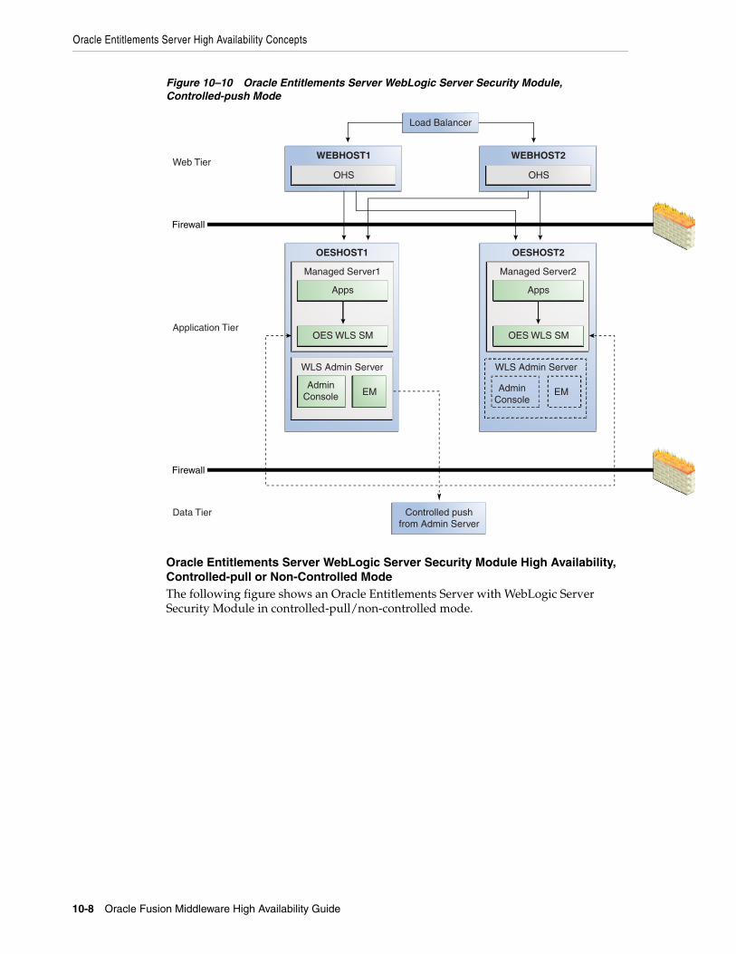
Oracle Entitlements Server High Availability Concepts
10-8 Oracle Fusion Middleware High Availability Guide
Figure 10–10 Oracle Entitlements Server WebLogic Server Security Module, Controlled-push Mode
Oracle Entitlements Server WebLogic Server Security Module High Availability, Controlled-pull or Non-Controlled ModeThe following figure shows an Oracle Entitlements Server with WebLogic Server Security Module in controlled-pull/non-controlled mode.
OESHOST2
Firewall
Firewall
OESHOST1
Managed Server1
Apps
Managed Server2
Apps
WEBHOST2WEBHOST1
OHS OHS
Load Balancer
Controlled push from Admin Server
Web Tier
Application Tier
Data Tier
WLS Admin Server
EMAdmin
Console
WLS Admin Server
EMAdminConsole
OES WLS SMOES WLS SM

Oracle Entitlements Server High Availability Concepts
Configuring High Availability for Oracle Entitlements Server 10-9
Figure 10–11 Oracle Entitlements Server WebLogic Server Security Module Controlled-pull/Non-Controlled Mode
10.1.2 Oracle Entitlements Server Security Module High AvailabilityWhen the Security Module reads policy from the OPSS security store for controlled-pull or non-controlled distribution, use Oracle-recommended high availability methods for an application accessing a database.
10.1.3 Load BalancingFor all high availability scenarios, you can deploy the load balancer:
■ In front of Authorization Policy Manager (APM) for user-to-APM communication. Oracle recommends a sticky connection to avoid losing data that does not persist to the policy store.
■ In front of the Web Service Security Module for client-to-Security Module communication. Oracle recommends a sticky connection to maximize cache usage.
OESHOST2
Firewall
Firewall
OESHOST1
Managed Server1
Apps
Managed Server2
Apps
WEBHOST2WEBHOST1
OHS OHS
RAC Database / OPSS Security Store
Load Balancer
Web Tier
Application Tier
Data Tier
WLS Admin Server
EMAdmin
Console
WLS Admin Server
EMAdminConsole
OES WLS SMOES WLS SM

Oracle Entitlements Server High Availability Concepts
10-10 Oracle Fusion Middleware High Availability Guide
10.1.4 Failover ConsiderationsThis section describes Oracle Entitlements Server failover considerations.
10.1.5 Protection from Failures and Expected BehaviorsThis section describes protection from different types of failure in an Oracle Entitlements Server active-active cluster.
■ Section 10.1.5.1, "Expected Client Application Behavior When Failure Occurs"
■ Section 10.1.5.2, "Node failure"
■ Section 10.1.5.3, "Database failure"
10.1.5.1 Expected Client Application Behavior When Failure OccursOracle Entitlements Server failover is not transparent. You must reestablish the connection during a WebLogic Server instance failover using Oracle Entitlements Server.
10.1.5.2 Node failureNode failures are treated in the same way as WebLogic Server crashes.
Note: Oracle Entitlements Server does not have any timeout requirements for the load balancer.
Table 10–1 Oracle Entitlements Server Failover Scenarios and Behavior
Failover Scenario Failover Behavior
OES Policy Store fails APM and Security Module in controlled-pull and uncontrolled mode switch to a working instance if multi-source data source is used. If the policy store instance is lost while the transaction is being processed:
■ APM returns an error to the user, who can repeat the request.
■ Security Module retries the transaction. Security Module uses only read operations. If Security Module is in controlled-pull mode, it uses the locally-persisted copy of the policy store.
OES Admin Server fails ■ User-to-APM communication - If a load balancer is present, it redirects the user to another APM instance. All unsaved data in the user session is lost, however, the user has full access to persisted policy data.
■ Security Module-to-APM communication - In controlled push distribution, Security Module registers with OES Admin on startup and retries the request to back-up instance if primary one is down. Retries continues until working instance is detected. While trying to reach OES Admin, Security Module uses a locally-persisted copy of the policy store.
Web Service Security Module or RMI Security Module fails
Security Module Proxy retries requests until it reaches the configured number of retries.
DB or LDAP attribute source fails
Security Module (OES Client) continues to try to read data until it reaches the configured number of retries.

Configuring Oracle Entitlements Server High Availability
Configuring High Availability for Oracle Entitlements Server 10-11
10.1.5.3 Database failureOracle Entitlements Server is protected against failures in the database by using multi data sources, which you configure during the initial system set up. The multi data sources guarantee that when an Oracle RAC database instance fails, the connections reestablish with available database instances. The multi data source allows you to configure connections to multiple instances in an Oracle RAC database.
10.1.6 Starting and Stopping the Oracle Entitlements Server ClusterIn a high availability architecture, you deploy Oracle Entitlements Server on a WebLogic cluster, which has at least two servers as part of the cluster.
By default, WebLogic Server starts, stops, monitors, and manages the various lifecycle events for the application. The Oracle Identity Manager application leverages the high availability features of the underlying Oracle WebLogic clusters. In case of hardware or other failures, session state is available to other cluster nodes that can resume the work of the failed node.
Use one or more of the following command line tools and consoles to manage Oracle Entitlements Server lifecycle events:
■ WebLogic Server Administration Console
■ Oracle Enterprise Manager Fusion Middleware Control
■ Oracle WebLogic Scripting Tool (WLST)
10.1.7 Cluster-Wide Configuration ChangesFor high availability environments, changing the configuration of one Oracle Entitlements Server instance changes the configuration of all the other instances, because all the Oracle Entitlements Server instances share the same configuration repository. Nearly all Oracle Entitlements Server deployments use cluster configurations. The only exception is Oracle Entitlements Server Administration Server, which is usually not clustered.
10.1.8 Considerations for Synchronizing with LDAPSynchronization between LDAP and the Oracle Entitlements Server database is handled by a process called Reconciliation, which is a scheduled process that runs in the background primarily. You can also run this process manually.
If an LDAP outage occurs during the Synchronization process, the data which did not get into Oracle Entitlements Server is picked up during the next run of the reconciliation task.
10.2 Configuring Oracle Entitlements Server High AvailabilityThis section provides high-level instructions for setting up a high availability deployment for Oracle Entitlements Server.
The Oracle Entitlements Server Administration Server high availability deployment is the same as a typical Oracle application.
To set up high availability for users accessing the Oracle Entitlements Server Administration Server user interface, use a WebLogic cluster.
To set up a high availability database for Administration Server user interface, you use multi source data source, Oracle RAC, and other typical elements.

Configuring Oracle Entitlements Server High Availability
10-12 Oracle Fusion Middleware High Availability Guide
This section includes the following topics:
■ Section 10.2.1, "Prerequisites for Oracle Entitlements Server Configuration"
■ Section 10.2.2, "Configure Weblogic Domain for OES Administration Server on OESHOST1"
■ Section 10.2.3, "Post-Configuration and Verification"
■ Section 10.2.4, "Configure OES Security Module in Controlled-push Mode with Oracle Entitlements Server Administration Server High Availability"
■ Section 10.2.5, "Configure Oracle Entitlements Server Security Module in Proxy Mode with PDP High Availability"
■ Section 10.2.6, "Configure Oracle Entitlements Server Policy Information Point with High Availability"
■ Section 10.2.7, "Configuring Oracle Entitlements Server Web Service Security Module on WebLogic High Availability"
■ Section 10.2.8, "Configuring Oracle Entitlements Server WebLogic Security Module High Availability"
■ Section 10.2.9, "Using RAC Datasource for Security Module in Controlled-pull Mode and Non-controlled Mode"
■ Section 10.2.10, "Configuring Oracle Entitlements Server to Work with the Web Tier"
10.2.1 Prerequisites for Oracle Entitlements Server ConfigurationComplete the following steps before you configure Oracle Entitlements Server high availability:
1. Use the Repository Creation Utility to create the Oracle Entitlements Server schemas in the Oracle RAC database. See Installation and Configuration Roadmap for Oracle Entitlements Server in the Oracle Fusion Middleware Installation Guide for Oracle Identity and Access Management for information on creating schemas.
2. Install Weblogic Server on OESHOST1 and OESHOST2. See Section 5.4.1.2, "Installing Oracle WebLogic Server" for more information.
3. Install the Oracle Entitlements Server Administration software on OESHOST1 and OESHOST2. See Installing Oracle Entitlements Server Administration Server in the Oracle Fusion Middleware Installation Guide for Oracle Identity and Access Management for more information.
4. Install the Oracle Entitlements Server Client. See Installing Oracle Entitlements Client in the Oracle Fusion Middleware Installation Guide for Oracle Identity and Access Management for more information.
10.2.2 Configure Weblogic Domain for OES Administration Server on OESHOST1To configure a WebLogic domain for the OES Administration Server on OESHOST1, perform these steps:
1. Run the MW_HOME/oracle_common/common/bin/config.sh script.
2. On the Welcome screen, select Create a new WebLogic domain and click Next. The Select Extension Source screen appears.
3. On the Select Extension Source screen, select Oracle Entitlements Server for Managed Server - 11.1.1.0[Oracle_IDM1. The Configuration Wizard automatically

Configuring Oracle Entitlements Server High Availability
Configuring High Availability for Oracle Entitlements Server 10-13
selects Oracle JRF, Oracle Platform Security Service, and Basic WebLogic Server Domain.
Click Next.
4. In the Specify Domain Name and Location screen, enter the domain name for the domain you are creating and the domain location. Click Next. The Configure Administrator User Name and Password screen appears.
5. Configure a user name and a password for the administrator. The default user name is weblogic. Click Next.
6. Choose the Weblogic domain startup mode and JDK in the Configure Server Start Mode and JDK screen.
7. In the Configure JDBC Component Schema screen, configure JDBC properties for all of the schemas then click Next.
8. On the Test JDBC Component Schema screen, click Select All then Test Connections. Click Next.
If the data source validation succeeds, click Next.
If the data source validation fails, click Previous, correct the issue, then try again.
9. On the Select Optional Configuration screen, select Administration Server and Managed Servers, Clusters and Machines. Click Next.
10. In the Configure the Administration Server screen, enter the following values:
■ Name: AdminServer
■ Listen address: All Local Addresses
■ Listen port: 7001
■ SSL listen port: 7002
■ Select SSL enabled
Click Next.
11. On the Configure Managed Servers screen, when you first enter the screen, one managed server called oes_server1 is created automatically. You can rename oes_server1 and update its attributes for this entry.
For example:
■ Name: oes_server1
■ Listen Address: OESHOST1.example.com
■ Listen Port: 14600
■ SSL Port: 14601
For the second OES_SERVER, click Add and enter the following values:
■ Name: oes_server2
■ Listen Address: OESHOST2.example.com
■ Listen Port: 14600
■ SSL Port: 14601
■ Select SSL enabled
Click Next.

Configuring Oracle Entitlements Server High Availability
10-14 Oracle Fusion Middleware High Availability Guide
12. In the Configure Clusters screen, click Add to create a cluster.
Enter the name oes_cluster. Select unicast for Cluster messaging mode, then enter the Cluster address in the format listen address or DNS name of oes_server1:port,listen address or DNS name of oes_server2:portmanaged server1:port,managed server2: port.
Click Next.
13. On the Assign Servers to Clusters screen, associate the managed servers with the cluster:
Click on the cluster name oes_cluster in the right window.
Click on the managed server oes_server1 then click the arrow to assign it to the cluster.
Repeat the preceding steps for the managed server oes_server2.
Click Next.
14. On the Configure Machines screen, create a machine for each host in the topology.
Click on the Unix tab.
For Admin Server Host:
■ Name: Name of your host. Use the DNS name here.
■ Node Manager Listen Address: Oracle recommends that the machine IP address be identical to the DNS name of the machine.
■ Node Manager Listen Port: Enter a port for Node Manager to use.
Leave all other values at the default settings.
Repeat the preceding steps for OESHOST1 and OESHOST2 and enter the following values. Leave all other values at the default settings.
■ Name: Name of the host. A good practice is to use the DNS name.
■ Node Manager Listen Address: Oracle recommends that the machine IP address be identical to the DNS name of the machine.
■ Node Manager Listen Port: Enter a port for Node Manager to use.
For Unix operating systems, delete the default local machine entry under the Machines tab.
Click Next.
15. On the Assign Servers to Machines screen, you assign the managed servers that will run on the machines you just created. Follow these steps:
Click on a machine in the right hand window.
Click on the managed servers you want to run on that machine in the left window.
Click on the arrow to assign the managed servers to the machine.
Repeat these steps until you assign all managed servers to the appropriate machine.
Assign servers to machines as follows:
■ ADMINHOST: Admin Server
■ OESHOST1: oes_server1
■ OESHOST2: oes_server2

Configuring Oracle Entitlements Server High Availability
Configuring High Availability for Oracle Entitlements Server 10-15
Click Next.
16. On the Configuration Summary screen, click Create.
17. Verify that the first RAC database instance in the OPSS security store configuration is running.
18. Configure the OPSS Security Store. See Configuring Security Store for OES Administration Server in the Oracle Fusion Middleware Installation Guide for Oracle Identity and Access Management.
10.2.3 Post-Configuration and VerificationThis section includes the following topics:
■ Section 10.2.3.1, "Starting Node Manager"
■ Section 10.2.3.2, "Validating the WebLogic Administration Server"
■ Section 10.2.3.3, "Creating a Separate Domain Directory for Managed Servers in the Same Node as the Administration Server"
■ Section 10.2.3.4, "Start Node Manager on Remote Hosts"
■ Section 10.2.3.5, "Stop and Start the WebLogic Administration Server and start oes_server1 and oes_server2"
10.2.3.1 Starting Node ManagerPerform these steps to start Node Manager on the administration host, for example, OESHOST1.
1. Run the startNodeManager.sh script located in the MW_HOME/wlserver_10.3/server/bin/ directory.
2. Run the setNMProps.sh script to set the StartScriptEnabled property to true:
cd MW_HOME/oracle_common/common/bin
3. Stop the Node Manager by killing the Node Manager process.
4. Start Node Manager.
10.2.3.2 Validating the WebLogic Administration ServerPerform the following steps to verify that the Administration server is configured properly.
1. Start Weblogic Administration Server by using ./startWeblogic.sh in the new domain.
2. In a browser, enter the URL for the Oracle WebLogic Server Administration Console, for example:
http://<OESHOST1>:7001/console
3. Log in as the WebLogic administrator, for example, weblogic.
10.2.3.3 Creating a Separate Domain Directory for Managed Servers in the Same Node as the Administration ServerUse the pack and unpack commands to separate the domain directory used by the Administration Server from the domain directory used by the managed server in OESHOST1.

Configuring Oracle Entitlements Server High Availability
10-16 Oracle Fusion Middleware High Availability Guide
To create a separate domain directory on OESHOST1:
1. Run the pack command to create a template pack as follows:
cd MW_HOME/oracle_common/common/bin
./pack.sh -managed=true -domain=ORACLE_BASE/admin/domain_name/aserver/domain_name -template=domaintemplate.jar -template_name=domain_template
2. Run the unpack command to unpack the template in the managed server domain directory as follows:
cd MW_HOME/oracle_common/common/bin
./unpack.sh -domain=ORACLE_BASE/admin/domain_name/mserver/domain_name -template=domaintemplate.jar
10.2.3.3.1 Propagate Changes to Remote Server Perform an unpack on remote hosts before you start managed servers on remote hosts, for example, OESHOST2.
1. Copy the file domaintemplate.jar created in Section 10.2.3.3, "Creating a Separate Domain Directory for Managed Servers in the Same Node as the Administration Server" to OESHOST2.
2. Run unpack on the host on OESHOST2 using the following commands:
cd MW_HOME/oracle_common/common/bin
./unpack.sh -domain=ORACLE_BASE/admin/domain_name/mserver/domain_name -template=domaintemplate.jar
10.2.3.4 Start Node Manager on Remote HostsTo start Node Manager on remote hosts, follow these steps:
1. On OESHOST2, start the Node Manager to create the nodemanager.properties file by using the startNodemanager.sh script located in the MW_HOME/wlserver_10.3/server/bin directory.
2. Run the setNMProps.sh script to set the StartScriptEnabled property to true:
cd MW_HOME/oracle_common/common/bin
./setNMProps.sh
3. Stop and start the Node Manager.
10.2.3.5 Stop and Start the WebLogic Administration Server and start oes_server1 and oes_server2
1. Restart the WebLogic Administration Server.
2. In a browser, enter the URL for the Oracle WebLogic Server Administration Console, for example:
http://<OESHOST1>:7001/console
3. Log in as the WebLogic administrator, for example, weblogic.
4. Start oes_server1 and oes_server2 managed servers from the WebLogic Server Admin console.

Configuring Oracle Entitlements Server High Availability
Configuring High Availability for Oracle Entitlements Server 10-17
5. Validate the OES Admin Server instance on OESHOST1 by opening the APM console at the URL http://<OESHOST1>:14600/apm
Log in with the WebLogic username and password.
6. Validate the OES Admin Server Instance on OESHOST2 by opening up the APM Console in a web browser at http://<OESHOST2>:14600/apm
10.2.4 Configure OES Security Module in Controlled-push Mode with Oracle Entitlements Server Administration Server High Availability
To configure the Oracle Entitlements Server Security Module in controlled-push mode with high availability, you set high availability parameters using the OES Security Module configuration user interface:
1. Change to the bin directory in the appropriate Security Module instance directory and run the following script on the command line.
cd $OES_CLIENT_HOME/oes_sm_instances/SM_Name/bin
2. Run oessmconfig.sh to start the SMConfig UI.
See Starting the SMConfig UI in the Oracle Fusion Middleware Administrator's Guide for Oracle Entitlements Server for more information.
3. Set the following parameters in the jps-config.xml file:
■ oracle.security.jps.runtime.pd.client.backupRegistrationServerURL
■ oracle.security.jps.runtime.pd.client.registrationRetryInterval
The following example shows the backupRegistrationServerURL used as a backup when the RegistrationServerURL fails.
<property name="oracle.security.jps.runtime.pd.client.backupRegistrationServerURL" value="https://slc00bqz:14601/pd-server"/>
See Configuring the Java Security Module in Oracle Fusion Middleware Administrator's Guide for Oracle Entitlements Server for more information.
10.2.5 Configure Oracle Entitlements Server Security Module in Proxy Mode with PDP High Availability
To configure the Security Module in proxy mode with PDP high availability:
1. See Using the Security Module Proxy Mode in the Oracle Fusion Middleware Administrator's Guide for Oracle Entitlements Server to configure the Security Module in proxy mode.
2. Change the PDP address by adding a comma-separated value as oracle.security.jps.pdp.proxy.PDPAddress
For example:
Note: You can also start the managed server by using the startManagedWebLogic.sh script in the domain directory subfolder bin. For example:
./startManagedWebLogic.sh oes_server1 http://localhost:7001

Configuring Oracle Entitlements Server High Availability
10-18 Oracle Fusion Middleware High Availability Guide
oracle.security.jps.pdp.proxy.PDPAddress=http://ws1:9410,http://ws2:9410
See PDP Proxy Client Configuration in the Oracle Fusion Middleware Administrator's Guide for Oracle Entitlements Server for more information.
10.2.6 Configure Oracle Entitlements Server Policy Information Point with High Availability
To configure the Policy Information Point high availability:
1. Change to the bin directory in the appropriate Security Module instance directory and run the following script on the command line:
cd $OES_CLIENT_HOME/oes_sm_instances/SM_Name/bin
2. Run oessmconfig.sh to start the SMConfig UI.
See Starting the SMConfig UI in the Oracle Fusion Middleware Administrator's Guide for Oracle Entitlements Server for more information.
3. Set attribute retriever parameters for Policy Information Point high availability. See Configuring Attribute Retrievers in the Oracle Fusion Middleware Administrator's Guide for Oracle Entitlements Server for more information.
10.2.7 Configuring Oracle Entitlements Server Web Service Security Module on WebLogic High Availability
You can configure Oracle Entitlements Server Web Service Security Module on WebLogic for high availability by means of a WebLogic cluster.
To configure Oracle Entitlements Server Web Service Security Module on WebLogic:
On OESHOST11. Run OESCLIENT_HOME/oessm/bin/config.sh to create a Web Service Security
Module and a WebLogic Server domain.
For example:
./config.sh -smType ws -onWLS -smConfigId <ws_name> -serverLocation <wls_home> -pdServer <oes_admin_server> -pdPort <oes_admin_ssl_port>
2. On the Welcome screen, select Create a WebLogic Domain then click Next.
3. On the Select Domain Source screen, select Generate a domain configured automatically to support the following added products. From the list, select Oracle Entitlements Server Web Service Security Module on Weblogic For Managed Server.
Click Next.
4. On the Specify Domain Name and Location screen, enter the name and location for the domain and all its applications:
Note: You can set multiple values for the ldap.url or jdbc.url attribute retriever parameter. Separate values with a comma; the first value is treated as the primary value. See Configuring the LDAP Repository Attribute Retriever Parameters in the Oracle Fusion Middleware Administrator's Guide for Oracle Entitlements Server.

Configuring Oracle Entitlements Server High Availability
Configuring High Availability for Oracle Entitlements Server 10-19
■ Domain Name: <domain name>
■ Domain Location: Accept the default entry.
5. On the Configure Administration Server Username and Password screen, enter the following:
■ Name: weblogic
■ User Password: Password for the WebLogic user
■ Confirm User Password: Password for the WebLogic user
■ Description: Description for the WebLogic user.
6. On the Configure Server Start Mode and JDK screen, select Production Mode and JDK.
7. On the Select Optional Configuration screen, select AdminServer and Managed Servers. Click Next.
8. On the Configure Administration Server screen, enter the following:
■ Name: AdminServer
■ Listen address: All Local Addresses
■ Listen port: 7001
■ SSL Listen port: 7002
Select SSL Enabled then click Next.
9. On the Configure Managed Servers screen, the default managed server wsonwls_server1 is created. Change the details of wsonwls_server1 and then add the second managed server:
For wsonwls_server1, enter these values:
■ Name: wsonwls_server1
■ Listen address: WSSMHOST1
■ Listen port: 14610
■ SSL listen port: 14611
For the second managed server, click Add and enter these values:
■ Name: wsonwls_server2
■ Listen address: WSSMHOST2
■ Listen port: 14610
■ SSL listen port: 14611
10. In the Configure Clusters screen, click Add and enter wssm_cluster. Select unicast for Cluster messaging mode then enter the Cluster address as managed_ server1:port,managed_server2: port
Click Next.
11. On the Assign Servers to Clusters screen, associate the managed servers with the cluster:
■ Click on the cluster wssm_cluster in the right window.
■ Click on the managed server wsonwls_server1 then click the arrow to assign it to the cluster.

Configuring Oracle Entitlements Server High Availability
10-20 Oracle Fusion Middleware High Availability Guide
Repeat the preceding steps for the managed server wsonwls_server2.
Click Next.
12. On the Configure Machines screen, create a machine for each host in the topology.
Click on the Unix tab for a Unix operating system.
For Admin Server Host:
■ Name: Name of your host. A good practice is to use the DNS name here.
■ Node Manager Listen Address: Oracle recommends that the machine IP address be identical to the DNS name of the machine.
■ Node Manager Listen Port: Enter a port for Node Manager to use.
Leave all other values at the default settings.
Repeat the preceding steps for WSSMHOST1 and WSSMOESHOST2 and enter the following values. Leave all other values at the default settings.
■ Name: Name of the host. A good practice is to use the DNS name.
■ Node Manager Listen Address: Oracle recommends that the machine IP address be identical to the DNS name of the machine.
■ Node Manager Listen Port: Enter a port for Node Manager to use.
For Unix operating systems, delete the default local machine entry under the Machines tab.
Click Next.
13. On the Assign Servers to Machines screen, assign the managed servers that will run on the machines you just created:
Click on a machine in the right hand window.
Click on the managed servers you want to run on that machine in the left window.
Click on the arrow to assign the managed servers to the machine.
Repeat these steps until you assign all managed servers to the appropriate machine.
Assign servers to machines as follows:
■ ADMINHOST: Admin Server
■ WSSMHOST1: wsonwls_server1
■ WSSMHOST2: wsonwls_server2
Click Next.
14. On the Configuration Summary screen, click Create.
15. Start Weblogic Administration Server by using ./startWeblogic.sh in the new domain.
16. Start Managed Server. Switch to created domain directory subfolder bin and type ./startManagedWebLogic.sh managed server name http://wlsadminserver host:wls_adminserver_port
For example:
./startManagedWeblogic.sh wsonwls_server1 http://localhost:7001

Configuring Oracle Entitlements Server High Availability
Configuring High Availability for Oracle Entitlements Server 10-21
On OESHOST2:Use the pack and unpack commands to separate the domain directory that the OES WebService SM uses from the domain directory that the managed server in OESHOST1 uses.
See the procedure to separate the domain directory in Section 10.1.1.5, "Oracle Entitlements Server WebLogic Server Security Module High Availability."
10.2.8 Configuring Oracle Entitlements Server WebLogic Security Module High Availability
You can configure Oracle Entitlements Server WebLogic Security Module for high availability by means of a WebLogic cluster.
To configure Oracle Entitlements Server WebLogic Security Module:
On OESHOST11. Run OESCLIENT_HOME/oessm/bin/config.sh to create a WebLogic Security Module
and a WebLogic Server domain.
For example:
./config.sh -smType wls -smConfigId <wls_name> -serverLocation <wls_home> -pdServer <oes_admin_server> -pdPort <oes_admin_ssl_port>
2. On the Welcome screen, select Create a WebLogic Domain then click Next.
3. On the Select Domain Source screen, select Generate a domain configured automatically to support the following added products. From the list, select Oracle Entitlements Server WebLogic Security Module on Weblogic For Managed Server.
Click Next.
4. On the Specify Domain Name and Location screen, enter the name and location for the domain and all its applications:
■ Domain Name: <domain name>
■ Domain Location: Accept the default entry.
5. On the Configure Administration Server Username and Password screen, enter the following:
■ Name: weblogic
■ User Password: Password for the WebLogic user
■ Confirm User Password: Password for the WebLogic user
■ Description: Description for the WebLogic user.
6. On the Configure Server Start Mode and JDK screen, select Production Mode and JDK.
7. On the Select Optional Configuration screen, select AdminServer and Managed Servers. Click Next.
8. On the Configure Administration Server screen, enter the following:
■ Name: AdminServer
■ Listen address: All Local Addresses
■ Listen port: 7001

Configuring Oracle Entitlements Server High Availability
10-22 Oracle Fusion Middleware High Availability Guide
■ SSL listen port: 7002
Select SSL Enabled then click Next.
9. On the Configure Managed Servers screen, the default managed server wlssm_server1 is created. Change the default managed server details and then add the second managed server:
For the default managed server, enter these values:
■ Name: wlssm_server1
■ Listen address: WLSSMHOST1
■ Listen port: 14610
■ SSL listen port: 14611
For the second managed server, click Add and enter these values:
■ Name: wlssm_server2
■ Listen address: WLSSMHOST2
■ Listen port: 14610
■ SSL listen port: 14611
10. In the Configure Clusters screen, click Add and enter wlssm_cluster. Select unicast for Cluster messaging mode then enter the Cluster address as managed_ server1:port,managed_server2: port
Click Next.
11. On the Assign Servers to Clusters screen, associate the managed servers with the cluster:
■ Click on the cluster wlssm_cluster in the right window.
■ Click on the managed server wlssm_server1 then click the arrow to assign it to the cluster.
Repeat the preceding steps for the managed server wlssm_server2.
Click Next.
12. On the Configure Machines screen, create a machine for each host in the topology.
Click on the Unix tab for a host that uses a Unix operating system.
For Admin Server Host:
■ Name: Name of your host. A good practice is to use the DNS name here.
■ Node Manager Listen Address: Oracle recommends that the machine IP address be identical to the DNS name of the machine.
■ Node Manager Listen Port: Enter a port for Node Manager to use.
Leave all other values at the default settings.
Repeat the preceding steps for WLSSHOST1 and WLSSMOESHOST2 and enter the following values. Leave all other values at the default settings.
■ Name: Name of the host. A good practice is to use the DNS name.
■ Node Manager Listen Address: Oracle recommends that the machine IP address be identical to the DNS name of the machine.
■ Node Manager Listen Port: Enter a port for Node Manager to use.

Configuring Oracle Entitlements Server High Availability
Configuring High Availability for Oracle Entitlements Server 10-23
For Unix operating systems, delete the default local machine entry under the Machines tab.
Click Next.
13. On the Assign Servers to Machines screen, you assign the managed servers that will run on the machines you just created. Follow these steps:
Click on a machine in the right hand window.
Click on the managed servers you want to run on that machine in the left window.
Click on the arrow to assign the managed servers to the machine.
Repeat these steps until you assign all managed servers to the appropriate machine.
Assign servers to machines as follows:
■ ADMINHOST: Admin Server
■ WLSSMHOST1: wlssm_server1
■ W:SSMHOST2: wlssm_server2
Click Next.
14. On the Configuration Summary screen, click Create.
15. Start Weblogic Administration Server by using ./startWeblogic.sh in the new domain.
16. Start Managed Server. Switch to created domain directory subfolder bin and type ./startManagedWebLogic.sh managed server name http://wlsadminserver host:wls_adminserver_port
For example:
./startManagedWeblogic.sh wlssm_server1 http://localhost:7001
Use the pack and unpack commands to separate the domain directory that WebLogic Server Security Module uses from the one that the managed server in OESHOST1 uses.
To create a separate domain directory on OESHOST1:
1. Run the pack command to create a template pack as follows:
cd MW_HOME/oracle_common/common/bin
./pack.sh -managed=true -domain=domain_path -template==domaintemplate.jar -template_name=domain_template
2. Run the unpack command to unpack the template in the managed server domain directory as follows:
cd MW_HOME/oracle_common/common/bin
./unpack.sh -domain=new_domain_path -template=domaintemplate.jar
Run the unpack operation on the remote hosts before you start the managed server, for example, OESHOST2.
3. Copy the file domaintemplate.jar from step 1. to OESHOST2.
4. Run unpack on the host on OESHOST2 using these commands:
cd MW_HOME/oracle_common/common/bin
./unpack.sh -domain=domain_path -template==domaintemplate.jar

Configuring Oracle Entitlements Server High Availability
10-24 Oracle Fusion Middleware High Availability Guide
5. Start the managed server then switch to the domain directory subfolder bin that you created. Enter ./startManagedWebLogic.sh managed_server_name http://wlsadminserver host:wls_adminserver_port
For example:
./startManagedWeblogic.sh wlssm_server2 http://localhost:7001
10.2.9 Using RAC Datasource for Security Module in Controlled-pull Mode and Non-controlled Mode
Connection to policy store is used for Oracle Entitlements Server Security Modules in controlled-pull mode and non-controlled mode. Due to an SMConfig UI limitation, you must configure JDBC properties at the time that you create Security Module instances.
To use a RAC datasource in WebLogic Server Security Modules or Web Service Security Modules on WebLogic Server, run the following steps after you create a Security Module instance:
1. Log in to Weblogic Administrator Console of the domain that Security Module is deployed in. Configure the RAC datasource with database information identical to that of the Oracle Entitlements Server Administration Server.
2. Edit the Security Module configuration with the SMConfig UI:
■ Run OES_CLIENT_HOME/oes_sm_instances/SM_Name/bin
■ Run oessmconfig.sh.
■ Select Database Configuration through JNDI Name and enter the RAC datasource JNDI name into the Data source JNDI Name field. Click Save & Close.
10.2.10 Configuring Oracle Entitlements Server to Work with the Web TierThis section describes how to configure Oracle Entitlements Server to work with the Oracle Web Tier and includes the following topics:
■ Section 10.2.10.1, "Prerequisites"
■ Section 10.2.10.2, "Configuring Oracle HTTP Servers to Front End the OES Managed Servers"
■ Section 10.2.10.3, "Validate the Oracle HTTP Server Configuration"
10.2.10.1 PrerequisitesVerify that the following tasks have been performed:
1. Oracle Web Tier has been installed on WEBHOST1 and WEBHOST2.
For instructions on installing Oracle HTTP Server on WEBHOST1 and WEBHOST2, see Section 8.5.3.5.1, "Installing Oracle HTTP Server for the Web Tier."
2. Oracle Entitlements Server has been installed and configured on OESHOST1 and OESHOST2.
3. The load balancer has been configured with a virtual hostname (sso.example.com) pointing to the web servers on WEBHOST1 and WEBHOST2.
4. The load balancer has been configured with a virtual hostname (oesinternal.example.com) pointing to web servers WEBHOST1 and WEBHOST2.

Configuring Oracle Entitlements Server High Availability
Configuring High Availability for Oracle Entitlements Server 10-25
10.2.10.2 Configuring Oracle HTTP Servers to Front End the OES Managed Servers
1. On each of the web servers on WEBHOST1 and WEBHOST2, create a file oes.conf in the directory ORACLE_INSTANCE/config/OHS/component/moduleconf. This file must contain the following information:
NameVirtualHost *:7777 <VirtualHost *:7777> ServerName http://sso.example.com:7777 RewriteEngine On RewriteOptions inherit UseCanonicalName On
# OES admin console <Location /apm>SetHandler weblogic-handler WebLogicCluster oeshost1.example.com:14600,oeshost2.example.com:14600 </Location>
2. Save the file on both WEBHOST1 and WEBHOST2.
3. Stop and start the Oracle HTTP Server instances on both WEBHOST1 and WEBHOST2.
10.2.10.3 Validate the Oracle HTTP Server Configuration To validate that Oracle HTTP Server is configured properly:
1. In a web browser, enter the following URL for the Oracle Identity Manager Console:
http://sso.example.com:7777/apm
2. In the APM login page, use weblogic user credentials to log in.

Configuring Oracle Entitlements Server High Availability
10-26 Oracle Fusion Middleware High Availability Guide

11
Configuring High Availability for Mobile and Social 11-1
11Configuring High Availability for Mobile andSocial
This chapter describes the Oracle Access Management Mobile and Social high availability framework. Topics include the following:
■ Section 11.1, "Oracle Access Management Mobile and Social Component Architecture"
■ Section 11.2, "Mobile and Social Component Characteristics"
■ Section 11.3, "Mobile and Social High Availability Concepts"
■ Section 11.4, "Configuring Mobile and Social High Availability"
11.1 Oracle Access Management Mobile and Social Component Architecture
Oracle Access Management Mobile and Social (Mobile and Social) is a lightweight security and identity solution that opens your existing Identity Management infrastructure to mobile and social networks. Mobile and Social integrates with existing IDM products including OAM and IGF. See Oracle Access Management Mobile and Social in Oracle Fusion Middleware Administrator's Guide for Oracle Access Management for more information on Mobile and Social.
Figure 11–1 shows the Mobile and Social component architecture.

Oracle Access Management Mobile and Social Component Architecture
11-2 Oracle Fusion Middleware High Availability Guide
Figure 11–1 Mobile and Social Component Architecture
The Oracle Access Management Mobile and Social service acts as an intermediary between a user who wants to access protected resources, and the back-end Access Management and Identity Management services that protect the resources. Mobile and Social provides simplified client libraries that allow developers to quickly add feature-rich authentication, authorization, and Identity capabilities to registered applications. On the back-end, the Mobile and Social server's pluggable architecture lets system administrators add, modify, and remove Identity and Access Management services without having to update user installed software.
11.1.1 Session State InformationNo session state is recorded for the Mobile Services component. For Internet Identity Services, short-lived tokens are kept in memory and discarded as soon as they expire.
11.1.2 Component LifecycleMobile and Social is a component in Access Suite J2EE application. You deploy and configure Mobile and Social as part of the Access Suite; the install, configuration, server instances are associated with the Access Suite.
As part of Mobile Services and Internet Identity Services, Mobile and Social provides HTTP interfaces for the clients to invoke. Mobile and Social processes those requests and returns a response, which the client may use to make additional requests. Mobile and Social is stateless, it can handle all requests sent by the client independently. Mobile and Social provides mobile device registration service and user authentication services using products like OAM, or by using social networks authentication and user profile services using Directory Servers.
Mobile and Social starts up as part of Access Suite server startup. MBean Server loads the Mobile and Social configuration.
11.1.3 Component Configuration ArtifactsUse the Administration Console or WLST commands to edit configuration files. Table 11–1 shows Mobile and Social configuration files and their location.

Mobile and Social High Availability Concepts
Configuring High Availability for Mobile and Social 11-3
11.1.4 Mobile and Social Deployment ArtifactsA Mobile and Social installation deploys the following components as part of oam-server.ear:
■ oic_rest.war
■ oic_rp.war
Table 11–2 shows Mobile and Social services deployment locations:
11.2 Mobile and Social Component CharacteristicsMobile and Social services consists of two subcomponents, Mobile Services and Internet Identity Services. Mobile Services provide Representational state transfer (REST) interfaces for authentication, user profile, and authorization services. Internet Identity Services provides integration with social network authentication.
See Introduction to Mobile Services in Oracle Fusion Middleware Administrator's Guide for Oracle Access Management for more information on Mobile and Social.
11.3 Mobile and Social High Availability ConceptsThis section describes the Mobile and Social high availability architecture and its elements. Topics include the following:
■ Section 11.3.1, "Mobile and Social High Availability Architecture"
■ Section 11.3.2, "Mobile and Social High Availability and Node Failover"
11.3.1 Mobile and Social High Availability ArchitectureFigure 11–1 shows Mobile and Social deployed in a high availability architecture in an active-active configuration.
Table 11–1 Mobile and Social Component Configuration Files
File Location
Idaas.xml <DOMAIN_HOME>/config/fmwconfig
oic_rp.xml <DOMAIN_HOME>/config/fmwconfig
Table 11–2 Mobile and Social Product Deployment Locations
Mobile and Social Product Deployment Location
Administration Server Administration Server user interface deploys as part of the OAM Admin .ear, oam-admin.ear
Managed Server, REST, and Internet Identity Services runtime
Deploy as part of the OAM Server .ear file, oam-server.ear

Mobile and Social High Availability Concepts
11-4 Oracle Fusion Middleware High Availability Guide
Figure 11–2 Mobile and Social High Availability Architecture
Figure 11–2 shows a typical client server architecture that supports multi-instance deployments. In most cases, requests are stateless, requiring no persistence. Mobile and Social services relies on other products, such as OAM/OID, that may have their own high availability capability. For the cases where state is maintained (Internet Identity authentication requests), high availability is achieved through sticky load balancing.
Requests can go to either server because there is no database persistence for sessions or runtime data. The load balancer returns requests to either Mobile and Social service 1 or 2 based on the policy set, such as Round Robin.
When an application invokes Internet Identity Services, control goes to a social network site such as Google, Facebook, or an Internet identity provider to process the request. When the response returns from the identity provider, it must return to the same server that initiates the request. With multiple Mobile and Social node deployments and when access is through the load balancer, requests to Mobile and Social must be pinned to the same server using the load balancer sticky sessions feature. Mobile and Social can further process the request after the Mobile and Social server that initiates the request to an IDP receives the IDP response.
You deploy Mobile and Social applications to all members in a cluster. The Mobile and Social application does not notify other cluster members when it successfully deploys on a cluster.
11.3.2 Mobile and Social High Availability and Node FailoverThis section describes elements of the Mobile and Social architecture that provide protection from node failure.
Note that if a node failover occurs, Mobile and Social follows standard WebLogic Server failover procedures. If node failure occurs before Mobile and Social completes a request that it receives from a client, the client receives an error through HTTP connections timeouts.
This section includes the following topics:
■ Section 11.3.2.1, "Load Balancing Requirements and Characteristics"
■ Section 11.3.2.2, "Session State Replication and Failover"
Identity Provider
Load Balancer
Mobile and Social service 2
Cache
Mobile and Social service 1
Cache
Identity providersends response to
identity provider URL
Mobile and Social service sends request
to identity provider

Configuring Mobile and Social High Availability
Configuring High Availability for Mobile and Social 11-5
■ Section 11.3.2.3, "Client Application Startup"
11.3.2.1 Load Balancing Requirements and CharacteristicsMobile and Social components are standard J2EE applications deployed on WebLogic Server 10.3, and conform to the standard for load balancing. Note the following:
■ You must use sticky session routing for Mobile and Social/RP requests, however, external load balancers are supported.
■ There is no intra-component load balancing.
■ There are no timeout requirements because there are no persistent connections.
11.3.2.2 Session State Replication and FailoverThe Mobile and Social high availability architecture relies on standard WebLogic Server clustering support for failover requirements. This architecture does not replicate the session state.
11.3.2.3 Client Application StartupWhen an Mobile and Social instance starts up, it does not affect the running system state. The Mobile and Social instance does not affect other running components or cluster members other than becoming a participant in WebLogic Server clustering scenarios.
11.3.2.3.1 Death Detection / Restart Use the Node Manager for Java EE components and OPMN for system components for death detection and component restart.
11.4 Configuring Mobile and Social High AvailabilityMobile and Social is part of the same managed server as Oracle Access Manager.
You can deploy Mobile and Social independently or with other components such as OAM, STS, and Identity Federation.
This section describes how to configure Mobile and Social high availability and includes the following topics:
■ Section 11.4.1, "Mobile and Social High Availability Requirements"
■ Section 11.4.2, "Modifying the WebGate Profile Configuration"
■ Section 11.4.3, "Modifying Token Service Provider Configuration in Mobile Security"
■ Section 11.4.4, "Modifying OAuth Service Provider Configuration in Federation"
11.4.1 Mobile and Social High Availability RequirementsNote the following Mobile and Social configuration prerequisites:
■ To configure Mobile and Social for high availability, you must install and configure OAM on multiple hosts in a high availability set up. See Chapter 6, "Configuring High Availability for Oracle Access Management Access Manager Components."
■ You must enable Mobile and Social if it is not enabled. Log into the Oracle Access Management Console, select the System configuration tab, open Available Services, and verify that the Mobile and Social status shows a green check.

Configuring Mobile and Social High Availability
11-6 Oracle Fusion Middleware High Availability Guide
■ You must configure OHS for oic_rest and oic_rp by adding the following mapping to the oam.conf file in ORACLE_INSTANCE/config/OHS/ohs1/moduleconf:
<Location /oic_rest> SetHandler weblogic-handler WebLogicCluster oamhost1.example.com:14100,oamhost2.example.com:14100 </Location>
<Location /oic_rp> SetHandler weblogic-handler WebLogicCluster oamhost1.example.com:14100,oamhost2.example.com:14100 </Location>
11.4.2 Modifying the WebGate Profile ConfigurationYou must modify the WebGate profile configuration to set up Mobile and Social high availability.
To modify the WebGate profile configuration:
1. Log into the OAM Console.
2. Go to the Launch Pad. Click Agents then click Search.
3. Select accessgate-oic to edit it.
4. Delete all entries in the Primary Server List.
5. Add the entry Other for Access Server and localhost as Host Name. The port number must match the existing port number.
6. Click Apply then save your changes.
11.4.3 Modifying Token Service Provider Configuration in Mobile SecurityYou must modify the Token Service Provider configuration to set up Mobile and Social high availability.
1. Log into the OAM Console.
2. Select the Mobile Security tab
3. Go to the Launch Pad. Select Mobile Authentication.
4. Click any Service Provider that depends on OAM, such as the following:
■ OAMAuthentication
■ OAMAuthorization
■ MobileOAMAuthentication
■ JWTOAMAuthentication
■ MobileJWTOAMAuthentication
Note: There must be multiple Primary Server List entries if you install multiple instances for this cluster.

Configuring Mobile and Social High Availability
Configuring High Availability for Mobile and Social 11-7
5. Change oam.OAM_SERVER_1 and oam.OAM_SERVER_2 to localhost. The port number must be identical to the existing port number.
11.4.4 Modifying OAuth Service Provider Configuration in Federation You must modify the OAuth Service Provider configuration in Federation.
1. Log into the OAM Console.
2. Select the Federation tab.
3. Go to Launch Pad. Select OAuth, Identity Domains, then Default Domain. Select Service Providers then OAuthServiceProvider.
4. Change oam.OAM_SERVER_1 and oam.OAM_SERVER_2 to localhost. The port number must be identical to the existing port number.

Configuring Mobile and Social High Availability
11-8 Oracle Fusion Middleware High Availability Guide

12
Configuring High Availability for Oracle Privileged Account Manager Components 12-1
12Configuring High Availability for OraclePrivileged Account Manager Components
This chapter describes the Oracle Privileged Account Manager high availability framework. Topics include the following:
Oracle Privileged Account Manager manages privileged accounts that are not being managed by any other Oracle Identity Management components. Accounts are considered privileged if they can access sensitive data, can grant access to sensitive data, or can both access and grant access to that data.
For a more detailed overview of Oracle Privileged Account Manager and its features, see "Understanding Oracle Privileged Account Manager" in the Oracle Fusion Middleware Administrator's Guide for Oracle Privileged Account Manager.
■ Section 12.1, "Oracle Privileged Account Manager Component Architecture"
■ Section 12.2, "Oracle Privileged Account Manager High Availability Concepts"
■ Section 12.3, "Oracle Privileged Account Manager High Availability Architecture"
■ Section 12.4, "Oracle Privileged Account Manager High Availability and Node Failure"
■ Section 12.5, "Oracle Privileged Account Manager High Availability Configuration"
12.1 Oracle Privileged Account Manager Component ArchitectureOracle Privileged Account Manager (OPAM) consists of a server, user interface, and session manager component that run as web applications. The server and user interface are web applications. Session Manager is a standard J2EE application with no web interface at this time. The OPAM server runs in a WebLogic Managed Server. The OPAM user interface is part of Oracle Identity Navigator (OIN) and also runs on the OPAM WebLogic Managed Server. OPAM Session Manager also runs on the Managed Server
The default and most simple configuration of OPAM deployment involves running a single OPAM managed server in a WebLogic domain. OPAM uses its own schema to store passwords to targets, accounts, and other items.
The following diagram illustrates Oracle Privileged Account Manager's architecture and topology:

Oracle Privileged Account Manager Component Architecture
12-2 Oracle Fusion Middleware High Availability Guide
Figure 12–1 Oracle Privileged Account Manager Component Architecture
Note the following features of this architecture:
■ All of Oracle Privileged Account Manager's core logic resides on the Oracle Privileged Account Manager Server. This functionality is exposed through a Representational state transfer (REST or RESTful) service, where the data is encoded as JavaScript Object Notation (JSON).
■ OPAM Session Manager is an OPAM sub-component that empowers OPAM Session Management capabilities. It is a J2EE application that interacts with the OPAM server by means of the OPAM RESTful interfaces, and shares the same database that OPAM Server uses. In addition, the OPAM Session Manager listens and responds to SSH traffic to establish privileged sessions against SSH capable OPAM targets.
■ Oracle Privileged Account Manager authentication relies on Java Authentication & Authorization Service (JAAS) support in WebLogic. Refer to "WebLogic Security Service Architecture" in Oracle® Fusion Middleware Understanding Security for Oracle WebLogic Server for more information about JAAS support in WebLogic.
■ All communication with, and between, Oracle Privileged Account Manager-related components (including Oracle Privileged Account Manager's Web-based user interface, command-line interface, and server) all occur over SSL
Note: Oracle Privileged Account Manager provides a Web-based user interface in Oracle Identity Navigator and an Oracle Privileged Account Manager Command Line Tool. Both interfaces are essentially clients of the Oracle Privileged Account Manager Server.
However, third parties can write their own clients, such as custom applications, by leveraging the open RESTful service. For more information, refer to Working with Oracle Privileged Account Manager's RESTful Interface in Oracle Fusion Middleware Administrator's Guide for Oracle Privileged Account Manager.

Oracle Privileged Account Manager Component Architecture
Configuring High Availability for Oracle Privileged Account Manager Components 12-3
■ Oracle Privileged Account Manager relies on and transparently uses the ID Store and Policy Store configured for the WebLogic domain in which Oracle Privileged Account Manager is deployed.
See How Oracle Privileged Account Manager is Deployed in Oracle Fusion Middleware in Oracle Fusion Middleware Administrator's Guide for Oracle Privileged Account Manager for more information.
■ The Oracle Privileged Account Manager Web-based user interface leverages, and is rendered by, Oracle Application Development Framework (ADF).
■ Oracle Privileged Account Manager connects to targets by using Identity Connector Framework (ICF) connectors. For additional information, see Understanding the Identity Connector Framework in the Oracle® Fusion Middleware Developer's Guide for Oracle Identity Manager.
This section includes the following topics:
■ Section 12.1.1, "Runtime Processes"
■ Section 12.1.2, "Process Lifecycle"
■ Section 12.1.3, "Session State"
■ Section 12.1.4, "External Dependencies"
■ Section 12.1.5, "Deployment Artifacts"
■ Section 12.1.6, "Log File Locations"
12.1.1 Runtime ProcessesOPAM server is the server component that runs WebLogic Managed Server. The OPAM Session Manager is a component that also runs on the OPAM Weblogic Managed Server. The OPAM user interface is a component that runs on the OPAM WebLogic Managed Server. OPAM server uses the REST protocol to communicate with clients including OPAM user interface and command line client. OPAM server uses the OPAM database as its data store. You can deploy OPAM server and the user interface in a WebLogic cluster with multiple servers and use WebLogic Console to manage the processes.
12.1.2 Process LifecycleOPAM server and OPAM Session Manager are J2EE applications deployed in WebLogic server.
During startup, the OPAM Lifecycle Listener checks whether the keystore is present for that domain.
■ If the keystore is not present, OPAM Lifecycle Listener creates a keystore using a randomly-generated keystore password, creates a keystore entry with domain name as alias, and updates the CSF with the keystore password.
■ If the keystore is present, it retrieves the keystore password from CSF and checks whether an entry is present with domain name as alias.
Because there is no operation if the keystore and required keystore CSF entry are present, a high availability environment for OPAM does not affect the process lifecycle.
OPAM Server uses a servlets model in which RESTful interfaces service clients. Therefore, the component lifecycle does not affect other running instances.

Oracle Privileged Account Manager High Availability Concepts
12-4 Oracle Fusion Middleware High Availability Guide
For more information on CSF, see Oracle Privileged Account Manager-Managed CSF Credentials in the Oracle Fusion Middleware Administrator's Guide for Oracle Privileged Account Manager.
12.1.3 Session StateOPAM server uses the REST-based communication; clients use HTTPS URLs. Session state information is not stored. Each communication completes an operation; sessions are not preserved.
OPAM Session Manager maintains the session state for each privileged session that it facilitates. After a session is established, the OPAM Session Manager instance used at session initiation time must continue it. If the OPAM Session Manager fails mid-session, a background thread cleans up orphaned sessions periodically.
12.1.4 External DependenciesOPAM server dependencies include the following:
■ ICF Connectors, for communication with target systems
■ External ID stores, for authentication (configurable in WebLogic)
The OPAM user interface and OPAM Command Line tool depend on the OPAM server. Client connections, which are REST using HTTPS URL, are short lived.
12.1.5 Deployment ArtifactsWhen you deploy OPAM to a managed server, Oracle Identity Navigator deploys to the Administration Server. The Oracle JRF deploys to both the Administration Server and Managed Server. Table 12–1 describes where OPAM product artifacts deploy.
12.1.6 Log File LocationsWebLogic Server Logs and Audit Logs save to the DOMAIN_HOME.
Audit Logs, if configured in WebLogic, save to the Audit database.
12.2 Oracle Privileged Account Manager High Availability ConceptsAt the cluster level, you can change OPAM properties such as connector directory and time limits.
All servers connect to a common domain OPAM data store, where configuration is maintained. Therefore, all connected servers pick up the shared data.
12.3 Oracle Privileged Account Manager High Availability ArchitectureFigure 12–2 shows Oracle Privileged Account Manager deployed in a high availability architecture in an active-active configuration.
Table 12–1 OPAM Deployment Artifacts
Location Product Artifact
Administration Server Oracle JRF
Managed Server OPAM server .ear file, OPAM session manager .ear file, Oracle Identity Navigator .ear file, Oracle JRF

Oracle Privileged Account Manager High Availability Architecture
Configuring High Availability for Oracle Privileged Account Manager Components 12-5
Figure 12–2 Oracle Privileged Account Manager in a High Availability Architecture
In this configuration, the Oracle Privileged Account Manager Servers are part of the same domain and use the same OPSS security store. Because multiple servers interact with the OPSS security store, Oracle recommends using the database as the OPSS backend.
In this cluster configuration, the same data is available from the different servers in the cluster. Each managed server has its own port configuration. The configuration includes a load balancer.
OPAMHOST1 has the following installations
■ An Oracle Privileged Account Manager instance in the WLS_OPAM1 Managed Server. The Oracle RAC database has been configured in a JDBC multi data source or GridLink data source to protect the instance from Oracle RAC node failure.
■ A WebLogic Server Administration Server. Under normal operations, this is the active Administration Server.
OPAMHOST2 has the following installations:
■ An Oracle Privileged Account Manager in the WLS_OPAM2 Managed Server. The Oracle RAC database is configured in a JDBC multi data source tor GridLink data source to protect the instance from Oracle RAC node failure.
The instances in the WLS_OPAM2 Managed Server and the instances in the WLS_OPAM1 Managed Server are configured as the CLUSTER_OPAM cluster.
■ A WebLogic Server Administration Server. Under normal operations, this is the passive Administration Server. You make this Administration Server active if the Administration Server on HOST1 becomes unavailable.
12.3.1 Starting and Stopping the ClusterBy default, WebLogic Server starts stops, monitors, and manages lifecycle events for the application. The Oracle Privileged Account Manager application leverages the high availability features of the underlying Oracle WebLogic Clusters. In case of

Oracle Privileged Account Manager High Availability and Node Failure
12-6 Oracle Fusion Middleware High Availability Guide
hardware or other failures, session state is available to other cluster nodes that can resume the work of the failed node.
In a high availability environment, WebLogic Node Manager is configured to monitor the WebLogic Servers. In case of failure, Node Manager restarts the WebLogic Server.
In high availability environments, the state and configuration information is stored a database that is shared by all the members of the cluster.
12.4 Oracle Privileged Account Manager High Availability and Node Failure
Note the following characteristics about Oracle Privileged Account Manager node failure in a high availability configuration:
■ Node failure does not affect clients.
■ If a server fails, ongoing REST-based operations stop; they do not fail over. Clients can connect to available servers and retry or continue with their requests. If you include a load balancer in the deployment, it directs requests to available servers.
12.5 Oracle Privileged Account Manager High Availability ConfigurationThis section provides high-level instructions for setting up a maximum high availability deployment for Oracle Privileged Account Manager High Availability. Topics in this section include the following:
■ Section 12.5.1, "Appropriate Development Environment"
■ Section 12.5.2, "Components Deployed"
■ Section 12.5.3, "Dependencies"
■ Section 12.5.4, "High Availability Configuration Procedure"
■ Section 12.5.5, "OHS Load Balancer Configuration"
12.5.1 Appropriate Development EnvironmentPerform the configuration in this topic if you want to configure Oracle Privileged Account Manager with Oracle Identity Navigator in a new WebLogic domain and then run the Oracle Identity Navigator discovery feature. This feature populates links to the product consoles for Oracle Identity Manager, Oracle Access Management, Oracle Adaptive Access Manager, and Oracle Privileged Account Manager. You can then access those product consoles from within the Oracle Identity Navigator interface, without having to remember the individual console URLs.
12.5.2 Components DeployedPerforming the configuration in this section deploys the Oracle Privileged Account Manager and Oracle Identity Navigator applications on a new WebLogic Administration Server.
12.5.3 DependenciesThe configuration in this section depends on the following:
■ Oracle WebLogic Server
■ Installation of the Oracle Identity and Access Management 11g software

Oracle Privileged Account Manager High Availability Configuration
Configuring High Availability for Oracle Privileged Account Manager Components 12-7
For more information, see Installing and Configuring Oracle Identity and Access Management in the Oracle Fusion Middleware Installation Guide for Oracle Identity and Access Management.
12.5.4 High Availability Configuration ProcedureThis section includes the following steps:
■ Section 12.5.4.1, "Configuring Oracle Identity and Access Management on OPAMHOST1"
■ Section 12.5.4.2, "Starting OPAMHOST1"
■ Section 12.5.4.3, "Configuring OPAM on OPAMHOST2"
■ Section 12.5.4.4, "Starting OPAMHOST2"
12.5.4.1 Configuring Oracle Identity and Access Management on OPAMHOST1To configure Oracle Privileged Account Manager and Oracle Identity Navigator for maximum high availability:
1. Install Oracle WebLogic Server and create a Middleware Home. See WebLogic Server and Middleware Home Requirements in Oracle Fusion Middleware Installation Guide for Oracle Identity and Access Management for more information.
2. Install the Oracle Identity and Access Management 11g software. See Installing Oracle Identity and Access Management in Oracle Fusion Middleware Installation Guide for Oracle Identity and Access Management for more information.
Optionally, Oracle Privileged Account Manager can operate with Oracle Database TDE (Transparent Data Encryption) mode. For more information, see "Optional: Enabling TDE in Oracle Privileged Account Manager Data Store" in the Installation Guide for Oracle Identity and Access Management.
3. Start the Configuration Wizard by running this command:
ORACLE_HOME/oracle_common/common/bin/config.sh
4. On the Welcome screen, select Create a new WebLogic domain and click Next. The Select Domain Source screen appears.
5. On the Select Domain Source screen, ensure that the Generate a domain configured automatically to support the following products: option is selected. Select Oracle Privileged Account Manager - 11.1.2.0.0 [IAM_Home].
Click Next. The Specify Domain Name and Location screen appears.
Note: You must run the config.sh script from your Oracle Identity and Access Management Home directory that contains Oracle Identity Manager, Access Manager, Oracle Adaptive Access Manager, Oracle Entitlements Server, Oracle Privileged Account Manager, Mobile and Social, and Oracle Identity Navigator.
Note: When you select the Oracle Privileged Account Manager - 11.1.2.0.0 [IAM_Home] option, the Oracle Identity Navigator, Oracle JRF, and Oracle Platform Security Service options are also selected by default.

Oracle Privileged Account Manager High Availability Configuration
12-8 Oracle Fusion Middleware High Availability Guide
6. Enter the domain name IDM_Domain. Keep the default Domain Location and Application Directory. Click Next. The Configure Administrator User Name and Password screen appears.
7. Configure a user name and a password for the administrator. The default user name is weblogic. Click Next.
8. Choose the JRE/JDK and Production Mode in the Configure Server Start Mode and JDK screen of the Oracle Fusion Middleware Configuration Wizard.
9. In the Configure JDBC Component Schema screen, enter the database schema details for the OPAM and OPSS schema.
(Optional) Select an option for RAC configuration for component schemas.
Click Next.
10. On the Test Component Schema screen, the Configuration Wizard tries to validate the data sources. Validate that the test for all schemas completes successfully.
If the data source validation succeeds, click Next.
If the data source validation fails, click Previous, correct the issue, then try again.
11. On the Select Optional Configuration screen, select the following:
■ Administration Server
■ Managed Servers, Clusters, and Machines
■ Deployments and Services
Click Next.
12. In the Customize Server and Cluster configuration screen, select Yes then Next.
13. In the Configure the Administration Server screen, enter the following values:
■ Name: AdminServer
■ Listen address: OPAMHOST1.example.com
■ Listen port: 7001
Do not set or change the following parameters:
■ SSL listen port: Not applicable
■ SSL enabled or disabled
Click Next.
14. On the Configure Managed Servers screen, create an entry for each OPAMHOST in the topology, that is, one entry for the OPAM server running on OPAMHOST1 and one entry for the OPAM server running on OPAMHOST2.
Select the OPAM_SERVER entry and change the entry to the following values:
■ Name: opamserver1
■ Listen Address: OPAMHOST1.example.com
■ Listen Port: 18101
Note: You can also use GridLink data sources. See Section 3.13, "GridLink Data Sources" for more information.

Oracle Privileged Account Manager High Availability Configuration
Configuring High Availability for Oracle Privileged Account Manager Components 12-9
■ SSL Port: 18102
For the second OPAM_SERVER, click Add and enter the following values:
■ Name: opam_server2
■ Listen Address: OPAMHOST2.example.com
■ Listen Port: 18101
■ SSL Port: 18102
Click Next.
15. In the Configure Clusters screen, click Add to create a cluster.
Enter a name for the cluster, such as OPAM_Cluster. Leave all other fields at their default setting.
Click Next.
16. On the Assign Servers to Clusters screen, associate the managed servers with the cluster:
Click on the cluster name OPAM_Cluster in the right window.
Click on the managed server opam_server1 then click the arrow to assign it to the cluster.
Repeat the preceding steps for the managed server opam_server2.
Click Next.
17. On the Configure Machines screen, create a machine for each host in the topology.
Click on the Unix tab if your hosts use a Unix operating system or click Machines.
Provide the following information:
■ Name: Name of the host. A good practice is to use the DNS name here.
■ Node Manager Listen Address: Enter the DNS name of the machine here.
■ Node Manager Port: Enter a port for Node Manager to use.
Repeat the preceding steps for OPAMHOST2 and enter the following values:
■ Name: Name of the host. A good practice is to use the DNS name, OPAMHOST2
■ Node Manager Listen Address: Enter the DNS name of the machine, OPAMHOST.example.com
■ Node Manager Port: Enter a port for Node Manager to use.
Click Next.
18. On the Assign Servers to Machines screen, assign the managed servers that will run on the machines you just created. Follow these steps:
Click on a machine in the right hand window.
Click on the managed servers you want to run on that machine in the left window.
Click on the arrow to assign the managed servers to the machine.
Repeat these steps until all managed servers are assigned to the appropriate machine.
For example:
■ Host1: Admin Server, OPAMHOST1, and opam_server1

Oracle Privileged Account Manager High Availability Configuration
12-10 Oracle Fusion Middleware High Availability Guide
■ Host2: OPAMHOST2 and opam_server2
Click Next.
19. On the Configuration Summary screen, click Create.
12.5.4.1.1 Configuring the Database Security Store You must configure the Database Security Store after you configure the domain but before you start the Administration Server. See Section 12.5.4.1.1, "Configuring the Database Security Store" for more information.
12.5.4.1.2 Starting Administration Server on OPAMHOST1 To start the Administration Server:
1. Go to DOMAIN_HOME/bin directory. Run startWeblogic.sh.
2. At the prompt, enter the WebLogic administrator username and password.
3. After the Administration Server is running, go to ORACLE_HOME/opam/bin directory. Run opam-config.sh.
4. At the prompt, enter the WebLogic username, password, URL, domain name, and middleware home.
5. Restart the Administration Server after opam-config.sh.
12.5.4.2 Starting OPAMHOST1This section describes the steps for starting OPAMHOST1:
1. Before you can start managed servers from the console, you must create a Node Manager property file. Run setNMProps.sh located in the following directory.
cd MW_HOME/oracle_common/common/bin
2. Start Node Manager with the command MW_HOME/wlserver_10.3/server/bin/startNodeManager.sh.
12.5.4.2.1 Starting Oracle Privileged Account Manager on OPAMHOST1 To start Oracle Privileged Account Manager on OPAMHOST1:
1. Log into the Administration Console using this URL:
http://opamhost1.example.com:7001/console
2. Enter the WebLogic administrator username and password.
3. Select Environment - Servers from the Domain Structure menu.
4. Click the Control tab.
Note: You perform the following steps when you start the Administration Server for the first time only.
Note: Before proceeding to the next step to run opam-config.sh, you must set the ORACLE_HOME, JAVA_HOME and ANT_HOME environment variables. ANT_HOME must point to a location that contains Ant and JAR binary files such as middleware_home/modules/org.apache.ant_1.7.1.

Oracle Privileged Account Manager High Availability Configuration
Configuring High Availability for Oracle Privileged Account Manager Components 12-11
5. Click the server opam_server1.
6. Click Start.
7. Click OK.
For more information, see "Assigning the Application Configurator Role to a User" and "Optional: Setting Up Non-TDE Mode" in Installation Guide for Oracle Identity and Access Management. Setting up non-TDE mode is required only if you did not set up TDE as Installation Guide for Oracle Identity and Access Management explains.
12.5.4.3 Configuring OPAM on OPAMHOST2After configuration succeeds on OPAMHOST1, you can propagate it to OPAMHOST2. You do this by packing the domain using the pack script on OPAMHOST1 and unpacking the domain using the unpack script on OPAMHOST2.
Both scripts reside in the MW_HOME/oracle_common/common/bin directory.
1. Verify that MW_HOME and ORACLE_HOME directory structure is identical to the OPAMHOST1 directory structure.
2. Enter the following on OPAMHOST1 to create the file idm_domain.jar in the /tmp directory:
pack.sh -domain=$MW_HOME/user_projects/domains/IDM_Domain -template=/tmp/idm_domain.jar -template_name="OPAM Domain" -managed=true
3. The previous step created the idm_domain.jar file in the /tmp directory.
Copy the idm_domain.jar file from OPAMHOST1 to a temporary directory on OPAMHOST2.
4. To copy idm_domain.jar to OPAMHOST2, enter the following:
unpack.sh -domain=MW_HOME/user_projects/domains/IDM_Domain -template=/tmp/idm_domain.jar
5. Copy jps-wls-trustprovider.jar from MW_HOME/oracle_common/modules/oracle.jps_11.1.1 to WLS_SERVER_HOME/server/lib/mbeantypes.
12.5.4.4 Starting OPAMHOST2This section describes the steps for starting OPAMHOST2.
1. Before you can start managed servers from the console, you must create a Node Manager property file. Run the script setNMProps.sh located in the following directory:
MW_HOME/oracle_common/common/bin
2. Start Node Manager with the command MW_HOME/wlserver_10.3/server/bin/startNodeManager.sh
3. Start Oracle Privileged Account Manager on OPAMHOST2. See Section 12.5.4.2.1, "Starting Oracle Privileged Account Manager on OPAMHOST1" and replace HOST1 and server1 with HOST2 and server2.
12.5.5 OHS Load Balancer ConfigurationYou can load balance OPAM servers using Oracle HTTP Server (OHS). This section provides the steps to configure OPAM to work with OHS. Topics include the following:

Oracle Privileged Account Manager High Availability Configuration
12-12 Oracle Fusion Middleware High Availability Guide
■ Section 12.5.5.1, "Configure SSL"
■ Section 12.5.5.2, "Update the Oracle HTTP Server Configuration"
■ Section 12.5.5.3, "Restart the Oracle HTTP Server"
12.5.5.1 Configure SSLBecause OPAM servers use SSL for communication, you must configure SSL options in the OHS Load Balancer. Follow these steps:
1. Enable the outbound SSL connections from OHS so that they can communicate with the OPAM managed/Administration servers. To do this, see Enable SSL for Outbound Requests from Oracle HTTP Server in the Oracle Fusion Middleware Administrator's Guide.
2. Enable inbound SSL connections into the OPAM managed/Administration servers. See Inbound SSL to Oracle WebLogic Server in the Oracle Fusion Middleware Administrator's Guide.
12.5.5.2 Update the Oracle HTTP Server ConfigurationOn the host where OHS is installed, create a file named opam.conf in the following directory:
ORACLE_INSTANCE/config/OHS/ohs1/moduleconf
Create the file with the following lines:
NameVirtualHost *:4443<VirtualHost *:4443>
ServerName http://opam.example.com:4443 ServerAdmin [email protected] RewriteEngine On RewriteOptions inherit
<Location /opam> SetHandler weblogic-handler WebLogicCluster opamhost1.example.com:18102,opamhost2.example.com:18102 WLCookieName OPAMSESSIONID WlSSLWallet "${ORACLE_INSTANCE}/config/${COMPONENT_TYPE}/${COMPONENT_ NAME}/keystores/ohs_wallet" WLProxySSL ON WLProxySSLPassThrough ON SecureProxy On </Location>
</VirtualHost>
<Location /oinav> SetHandler weblogic-handler WebLogicCluster opamhost1.example.com:18102,opamhost2.example.com:18102 WLCookieName OPAMSESSIONID WlSSLWallet "${ORACLE_INSTANCE}/config/${COMPONENT_TYPE}/${COMPONENT_ NAME}/keystores/ohs_wallet" WLProxySSL ON WLProxySSLPassThrough ON SecureProxy On </Location>
</VirtualHost>

Oracle Privileged Account Manager High Availability Configuration
Configuring High Availability for Oracle Privileged Account Manager Components 12-13
To configure OHS for the OPAM console, update the opam.conf file with the following lines:
NameVirtualHost *:7777<VirtualHost *:7777>
ServerName http://opam.example.com:7777 ServerAdmin [email protected] RewriteEngine On RewriteOptions inherit
<Location /oinav> SetHandler weblogic-handler WebLogicCluster opamhost1.example.com:18101,opamhost2.example.com:18101 WLCookieName OPAMSESSIONID </Location>
</VirtualHost>
12.5.5.3 Restart the Oracle HTTP Server To restart Oracle HTTP Server, run the following commands from ORACLE_INSTANCE/bin:
opmnctl stopallopmnctl startall

Oracle Privileged Account Manager High Availability Configuration
12-14 Oracle Fusion Middleware High Availability Guide

13
Configuring High Availability for Oracle Mobile Security Suite 13-1
13Configuring High Availability for Oracle MobileSecurity Suite
[1] This chapter describes how to configure high availability for Oracle Mobile Security Suite server components.
This chapter includes the following topics:
■ Section 13.1, "About Oracle Mobile Security Suite High Availability"
■ Section 13.2, "Oracle Mobile Security Suite High Availability Architecture"
■ Section 13.3, "Required Installations for Oracle Mobile Security Suite"
■ Section 13.4, "Configuring High Availability for Oracle Mobile Security Manager"
■ Section 13.5, "Configuring High Availability for Oracle Mobile Security Access Server"
See the following documents for information on Oracle Mobile Security Suite.
13.1 About Oracle Mobile Security Suite High AvailabilityThere are two server components in the Oracle Mobile Security Suite that you configure for high availability.
■ Mobile Security Manager (OMSM) running in WLS
■ Mobile Security Access Server (MSAS) running as a standalone application
OMSS requires Oracle Access Manager (OAM) for user authentication and SSO support. OMSS also requires the Policy Manager Console. See Chapter 6, "Configuring High Availability for Oracle Access Management Access Manager Components." for more information.
For more information on OMSS, see "Understanding Oracle Mobile Security Suite" in Administering Oracle Mobile Security.
Table 13–1 Oracle Mobile Security Suite
Product Resource
Oracle Mobile Security Suite Installing Oracle Mobile Security Access Server
Oracle Fusion Middleware Installation Guide for Oracle Identity Management
Mobile Security Manager Administering Oracle Mobile Security Suite
Mobile Security Access Server
Administering Mobile Security Access Server

Oracle Mobile Security Suite High Availability Architecture
13-2 Oracle Fusion Middleware High Availability Guide
For more information on high availability, see Section 1.1, "What is High Availability".
13.2 Oracle Mobile Security Suite High Availability ArchitectureThe following figure shows Oracle Mobile Security Suite in a high availability architecture:
Figure 13–1 OMSS High Availability Architecture
Mobile Security Access Server In this architecture, the Web Tier has one logical Mobile Security Access Server (MSAS) instance that includes multiple physical MSAS instances. The physical instances can run on different hosts, or on one host on different ports. Each physical instance has the same MSAS ID so that the instances can synchronize. MSAS synchronization occurs over HTTP(S).
Oracle Mobile Security ManagerIn this configuration, the Mobile Security Manager (OMSM) Servers are part of the same domain and use the same RAC database.
WEBHOST2
OHS
mod_wl_ohs
WebGateMSASproxy
OAMHOST2OAMHOST1
RAC Database
WEBHOST1
OHS
mod_wl_ohs
VIP: ovd.example.com VIP: oid.example.com
WLS Admin Server
OAM Console
Admin Console
WLS Admin Server
OAM Console
Admin Console
Load Balancer
HTTP HTTP
Firewall
Firewall
WLS_MSM1
msm_cluster
WLS_MSM2
WLS_OAM1 WLS_OAM2
oam_cluster
ama_cluster
WLS_AMA1 WLS_AMA2
MSAS logical instance
WebGateMSASproxy

Required Installations for Oracle Mobile Security Suite
Configuring High Availability for Oracle Mobile Security Suite 13-3
This configuration has two Managed Servers that Mobile Security Manager (OMSM) is deployed to. Both Managed Servers are part of msm_cluster and they connect to same RAC database.
OAMHOST1 has the following installations
■ An OAM Managed Server instance, WLS_OAM1.
■ An Oracle Mobile Security Manager instance, WLS_MSM1.
■ An OAM Policy Manager instance, WLS_AMA1.
■ The Oracle RAC database is configured in a JDBC multi data source or GridLink data source to protect the instance from Oracle RAC node failure.
■ An Administration Server. Under normal operations, this is the active Administration Server.
OAMHOST2 has the following installations:
■ An OAM Managed Server instance, WLS_OAM2.
WLS_OAM1 and WLS_OAM2 Managed Servers are configured as a cluster.
■ An MSM Managed Server instance, WLS_MSM2.
WLS_MSM1 and WLS_MSM2 Managed Servers are configured as a cluster.
■ An OAM Policy Manager instance, WLS_AMA2.
WLS_AMA1 and WLS_AMA2 Managed Servers are configured as a cluster.
■ The Oracle RAC database is configured in a JDBC multi data source tor GridLink data source to protect the instance from Oracle RAC node failure.
■ A WebLogic Server Administration Server. Under normal operations, this is the passive Administration Server. You make this Administration Server active if the Administration Server on OAMHOST1 becomes unavailable.
13.3 Required Installations for Oracle Mobile Security SuiteYou must install the following components on host systems before you configure OMSS:
■ Oracle WebLogic Server
■ Oracle Access Manager
■ Oracle Mobile Security Manager
■ Oracle Mobile Security Access Server
Note: MW_HOME and ORACLE_HOME must be in identical locations on both OAMHOST1 and OAMHOST2.
Product Installation See this resource
WebLogic Server "Installing Oracle WebLogic Server and Creating a Middleware Home" in Installation Guide for Oracle Identity and Access Management
Oracle Access Manager Installation Guide for Oracle Identity and Access Management

Configuring High Availability for Oracle Mobile Security Manager
13-4 Oracle Fusion Middleware High Availability Guide
13.4 Configuring High Availability for Oracle Mobile Security ManagerThis section includes the following procedures to configure Oracle Mobile Security Manager (OMSM) high availability.
■ Section 13.4.1, "Configuring Oracle Mobile Security Manager on OAMHOST1"
■ Section 13.4.2, "Starting OAMHOST1"
■ Section 13.4.3, "Starting Oracle Mobile Security Manager on OAMHOST1"
■ Section 13.4.4, "Configuring Oracle HTTP Server"
■ Section 13.4.5, "Starting Managed Servers and Node Manager on OAMHOST2"
13.4.1 Configuring Oracle Mobile Security Manager on OAMHOST1In this procedure, you create the Oracle Mobile Security Manager (OMSM) Managed Servers, cluster, and machine.
To configure OMSM on OAMHOST1:
1. Install Oracle WebLogic Server and create a Middleware Home. See WebLogic Server and Middleware Home Requirements in Oracle Fusion Middleware Installation Guide for Oracle Identity and Access Management for more information.
2. Install the Oracle Mobile Security Manager software. See Installation Guide for Oracle Identity and Access Management for more information.
3. Start the Configuration Wizard by running this command:
ORACLE_HOME/oracle_common/common/bin/config.sh
4. On the Welcome screen, select Create a new WebLogic domain. Click Next.
5. On the Select Domain Source page, ensure that Generate a domain configured automatically to support the following products: is selected. Select Oracle Access Management and Mobile Security Suite - 11.1.2.3.0 and click Next.
Oracle Mobile Security Manager
Installation Guide for Oracle Identity and Access Management
Oracle Mobile Security Access Server
Installing Mobile Security Access Server (MSAS)
Note: You must run the config.sh script from your Oracle Identity and Access Management Home directory that contains Access Manager.
Product Installation See this resource

Configuring High Availability for Oracle Mobile Security Manager
Configuring High Availability for Oracle Mobile Security Suite 13-5
Click Next.
6. Enter the domain name, such as MSM_Domain. Keep the default Domain Location and Application Directory. Click Next.
7. Configure a user name and a password for the administrator in the Configure Administrator User Name and Password screen. The default user name is weblogic. Click Next.
8. Choose the JRE/JDK and Production Mode in the Configure Server Start Mode and JDK screen.
9. Enter database schema details for the OMSM, OAM Infrastructure, and OPSS schemas in the Configure JDBC Component Schema screen.
(Optional) Select an option for RAC configuration for component schemas.
Click Next.
10. On the Test Component Schema screen, the Configuration Wizard validates the data sources. Verify that the test for all schemas completes successfully.
If data source validation succeeds, click Next.
If data source validation fails, click Previous, correct the issue, then try again.
11. On the Select Optional Configuration screen, select the following:
■ Administration Server
■ Managed Servers, Clusters, and Machines
■ Deployments and Services
■ RDBMS Security Store (Optional)
Click Next.
12. In the Customize Server and Cluster configuration screen, select Yes then Next.
13. In the Configure the Administration Server screen, enter these values:
■ Name: AdminServer
■ Listen address: HOST1.example.com
■ Listen port: 7001
Do not set or change the following parameters:
Note: Selecting Oracle Access Management and Mobile Security Suite - 11.1.2.3.0 option selects the following options by default:
■ Oracle Enterprise Manager
■ Oracle WSM Policy Manager
■ Oracle JRF
■ Oracle Platform Security Service
■ Oracle OPSS Metadata for JRF
Note: You can also use GridLink data sources. See Section 3.13, "GridLink Data Sources" for more information.

Configuring High Availability for Oracle Mobile Security Manager
13-6 Oracle Fusion Middleware High Availability Guide
■ SSL listen port: Not applicable
■ SSL enabled or disabled
Click Next.
14. On the Configure Managed Servers screen, create the following entries for each host in the topology.
Select the WLS_MSM1 entry and change it to the following values:
■ Name: WLS_MSM1
■ Listen Address: HOST1.example.com
■ Listen Port: 14180
■ SSL Port: 14181
For the second server, WLS_MSM2, click Add and enter the following values:
■ Name: WLS_MSM2
■ Listen Address: HOST2.example.com
■ Listen Port: 14180
■ SSL Listen Port: 14181
Select the WLS_OAM1 entry and change the entry to the following values:
■ Name: WLS_OAM1
■ Listen Address: HOST1.example.com
■ Listen Port: 14100
For the second server, WLS_OAM2, click Add and enter the following values:
■ Name: WLS_OAM2
■ Listen Address: HOST2.example.com
■ Listen Port: 14100
Select the WLS_ama1 entry and change the entry to the following values:
■ Name: WLS_AMA1
■ Listen Address: HOST1.example.com
■ Listen Port: 14150
For the second server, WLS_AMA2, click Add and enter the following values:
■ Name: WLS_AMA2
■ Listen Address: HOST2.example.com
■ Listen Port: 14150
Click Next.
15. In the Configure Clusters screen, click Add to create a cluster.
Enter names for each cluster, such as msm_cluster, oam_cluster, ama_cluster. Leave all other fields at their default setting.
Click Next.
16. On the Assign Servers to Clusters screen, associate Managed servers with the cluster:

Configuring High Availability for Oracle Mobile Security Manager
Configuring High Availability for Oracle Mobile Security Suite 13-7
Click on the cluster name msm_cluster in the right window.
For each MSM Managed Server, click on the Managed Server name then click the arrow to assign it to the cluster.
Repeat the preceding steps for oam_cluster and ama_cluster, assigning the appropriate Managed Servers to each cluster.
Click Next.
17. On the Configure Machines screen, create a machine for each host in the topology.
Click on the Unix tab if your hosts use a Unix operating system or click Machines.
Provide the following information:
■ Name: Host name. A good practice is to use the DNS name.
■ Node Manager Listen Address: HOST1.example.com
■ Node Manager Port: Port for Node Manager to use.
Repeat the preceding steps for OAMHOST2 and enter these values:
■ Name: Host name. A good practice is to use the DNS name, HOST2
■ Node Manager Listen Address: Machine DNS name, HOST2.example.com
■ Node Manager Port: Port for Node Manager to use.
Click Next.
18. On the Assign Servers to Machines screen, assign Managed Servers to run on the machines you just created:
Select a machine in the right window.
Select Managed Servers you want to run on that machine in the left window.
Click the arrow to assign managed servers to the machine.
Repeat these steps until you assign:
■ AdminServer to Machine 1
■ Managed Servers WLS_OAM1, WLS_MSM1, and WLS_AMA1 to Machine 1
■ Managed Servers WLS_OAM2, WLS_MSM2, and WLS_AMA2 to Machine 2
Click Next.
19. Review Configuration Summary screen selections then click Create.
20. Configure the security store. See "Configuring Database Security Store for an Oracle Identity and Access Management Domain" in Oracle Fusion Middleware Installation Guide for Oracle Identity and Access Management.
21. Start the Administration Server.
22. Run the idmConfigTool configuration commands located in IAM_HOME/idmtools/bin as "Running IDM Configuration Tool to Configure Oracle Access Manager" describes in Oracle Fusion Middleware Installation Guide for Oracle Identity Management
Note: For more information on idmConfigTool, see "Using the idmConfigTool Command" in Oracle Fusion Middleware Integration Guide for Oracle Identity Management Suite.

Configuring High Availability for Oracle Mobile Security Manager
13-8 Oracle Fusion Middleware High Availability Guide
23. Run the IdmConfigTool OMSM configOMSS command as "Configuring Oracle Mobile Security Manager Using IDM Configuration Tool" describes in Oracle Fusion Middleware Installation Guide for Oracle Identity Management. You must enter the following properties for a high availability set up; see configOMSS Command for information on configOMSS syntax and properties:
24. Stop the Administration Server.
25. Verify that WebLogic Server and OAM are installed on OAMHOST2, and that the MW_HOME and ORACLE_HOME directory structure is identical to the OAMHOST1 directory structure. See "Running the Environment Health Check Utility to Verify Oracle Access Manager" in Installation Guide for Oracle Identity and Access Management for more information.
26. Copy the domain you created on OAMHOST1 to OAMHOST2. Run the pack command on OAMHOST1 to pack the domain directory. For example, the following command packs the domain in omsm_packed.jar.
ORACLE_HOME is the home directory where you installed the Identity Management product.
$ORACLE_HOME/common/bin/pack.sh -domain=$MW_HOME/user_projects/domains/new_domain -template=/scratch/omsm_packed.jar -template_name="Oracle Mobile Security Manager" -managed=true
27. Use the sftp or scp command to copy the template file that the domain was packed in from OAMHOST1 to OAMHOST2.
28. On OAMHOST2, create a domain using the template file that you copied from OAMHOST1. This is the file that you unpacked on OAMHOST2. Run the unpack command to copy the template jar to OAMHOST (for example, to the directory /scratch/omsm_packed.jar). In the following example, the unpack command creates a domain on OAMHOST2.
$ORACLE_HOME/common/bin/unpack.sh -domain=$MW_HOME/user_projects/domains/new_domain -template=/scratch/omsm_packed.jar
13.4.2 Starting OAMHOST1To start OAMHOST1:
1. Before you start Managed Servers from the console, you must create a Node Manager property file. Run setNMProps.sh located in the MW_HOME/oracle_common/common/bin directory.
2. Start Node Manager with the command MW_HOME/wlserver_10.3/server/bin/startNodeManager.sh.
Property Value
OMSS_OMSM_FRONT_END_URL OHS URL, for example, http://host:port/
OMSS_MANAGED_SERVER_NAME Comma-separated names of all MSM Managed Servers, for example WLS_MSM1,WLS_MSM2
OMSS_OAM_POLICY_MGR_SERVER_NAME
Comma-separated names of all Policy Manager Managed Servers, for example, WLS_AMA1,WLS_AMA2

Configuring High Availability for Oracle Mobile Security Manager
Configuring High Availability for Oracle Mobile Security Suite 13-9
13.4.3 Starting Oracle Mobile Security Manager on OAMHOST1To start Oracle Mobile Security Manager on OAMHOST1:
1. Start Administration Server using Node Manager or the startWebLogic.sh script:
DOMAIN_HOME/bin/startWebLogic.sh
See Starting and Stopping Administration Servers in Administrator's Guide for details on the Administration Server.
2. Log into the Administration Console using this URL:
http://host1.example.com:7001/console
3. Enter the WebLogic administrator username and password.
4. Select Environment - Servers from the Domain Structure menu.
5. Click the Control tab.
6. Click the server WLS_MSM1.
7. Click Start then click OK.
13.4.4 Configuring Oracle HTTP ServerOracle HTTP Server front ends the clusters. You configure OHS instead of using a Proxy Server.
Run these steps on each of the web tier hosts on which Oracle HTTP Server is installed (for example, WEBHOST1 and WEBHOST2)
To configure Oracle HTTP Server:
1. Verify that OHS is installed on the system.
2. Stop OHS using the command:
OHS_INSTANCE_HOME/bin/opmnctl stopall
3. Copy ORACLE_HOME/omss/omsm/config/omss.conf to OHS_INSTANCE_HOME/config/OHS/ohs instance name/module.conf
4. Open the file OHS_INSTANCE_HOME/config/ohs/config/OHS/instance name/moduleconf/omss.conf.
Change all instances of the line WebLogicCluster HOST1:port,HOST2:port to reflect your installation, for example:
WeblogicCluster host1.example.com:14180,host2.example.com:14180
The following example shows lines you must add to the file for OMSS:
<Location /msm> SetHandler weblogic-handler WebLogicCluster host1.example.com:14180,host2.example.com:14180 WLLogFile "$ORACLE_INSTANCE/diagnostics/logs/mod_wl/msm_component.log"
Note: After you start WLS_MSM, you must also start the Managed Servers WLS_OAM and WLS_AMA.
Note: The Oracle HTTP Server should not run OAM WebGate.

Configuring High Availability for Oracle Mobile Security Manager
13-10 Oracle Fusion Middleware High Availability Guide
</Location>
# MSM runtime services for MAM<Location /ecp> SetHandler weblogic-handler WebLogicCluster host1.example.com:14180,host2.example.com:14180 WLLogFile "$ORACLE_INSTANCE/diagnostics/logs/mod_wl/msm_component.log"</Location>
# Mobile File Manager <Location /mfm> SetHandler weblogic-handler WebLogicCluster host1.example.com:14180,host2.example.com:14180 WLLogFile "$ORACLE_INSTANCE/diagnostics/logs/mod_wl/msm_component.log"</Location>
# MSAS management services<Location /gms-rest> SetHandler weblogic-handler WebLogicCluster host1.example.com:14180,host2.example.com:14180 WLLogFile "$ORACLE_INSTANCE/diagnostics/logs/mod_wl/msm_component.log"</Location>
# MSAS management rest services<Location /msm-mgmt> SetHandler weblogic-handler WebLogicCluster host1.example.com:14180,host2.example.com:14180 WLLogFile "$ORACLE_INSTANCE/diagnostics/logs/mod_wl/msm_component.log"</Location>
# MSM console<Location /msmconsole> SetHandler weblogic-handler WebLogicCluster host1.example.com:14180,host2.example.com:14180 WLLogFile "$ORACLE_INSTANCE/diagnostics/logs/mod_wl/msm_component.log"</Location>
<Location /ms_oauth> SetHandler weblogic-handler Debug ON WLLogFile /tmp/weblogic.log WLProxySSL ON WLProxySSLPassThrough ON# WLCookieName OAM_JSESSIONID WLCookieName OAMSESSIONID WebLogicCluster host1:14100,host2:14100</Location>
5. Save the file.
6. Start OHS on both hosts.
OHS_INSTANCE_HOME/bin/opmnctl startall
13.4.5 Starting Managed Servers and Node Manager on OAMHOST2To start Managed Servers and Node Manager on OAMHOST2:
1. Start Node Manager on OAMHOST2.
WL_HOME/server/bin/startNodeManager.sh

Configuring High Availability for Oracle Mobile Security Access Server
Configuring High Availability for Oracle Mobile Security Suite 13-11
2. Start Administration Server using Node Manager or the startWebLogic.sh script:
DOMAIN_HOME/bin/startWebLogic.sh
See Starting and Stopping Administration Servers in Administrator's Guide for details on the Administration Server.
3. Log into the Administration Console using this URL:
http://host2.example.com:7001/console
4. Enter the WebLogic administrator username and password.
5. Select Environment - Servers from the Domain Structure menu.
6. Click the Control tab.
7. Click the server msm_server2.
8. Click Start then click OK.
13.5 Configuring High Availability for Oracle Mobile Security Access Server
Mobile Security Access Server (MSAS), a component in the Oracle Mobile Security Suite, provides a central access point for securing traffic from mobile devices to intranet resources. MSAS is an application running its own server process in the Web Tier. You manage it with OMSM.
MSAS continues to operate even if MSM is down. If MSM is down, MSAS does not retrieve completed management/artifact changes by means of the user interface or WLST in MSM. However, MSAS does continue to enforce security.
MSAS has a persistent local file based cache so that it can continue to run if you take it down and bring it back up.
See the following topics to configure MSAS high availability:
■ Section 13.5.1, "High Availability Requirements"
■ Section 13.5.2, "Starting OMSM Managed Server"
■ Section 13.5.3, "Configuring Physical MSAS Instances"
■ Section 13.5.4, "Starting MSAS Instances"
■ Section 13.5.5, "Configuring the Load Balancer for MSAS"
13.5.1 High Availability RequirementsBefore you start configuring high availability, you must have at least two instances of MSAS installed on the Web Tier. You can have these instances on different hosts or on the same host on different ports. MSAS supports both configurations.
To install MSAS, see Oracle Fusion Middleware Installing Oracle Mobile Security Access Server.
Note: MSM must be running the first time you start MSAS so that it can retrieve initial artifacts.

Configuring High Availability for Oracle Mobile Security Access Server
13-12 Oracle Fusion Middleware High Availability Guide
For information on MSAS administration and tools, see "MSAS Administration Tools" in Oracle Fusion Middleware Administering Mobile Security Access Server.
13.5.2 Starting OMSM Managed ServerYou must start OMSM to configure MSAS because MSAS must connect to OMSM at least once to create a new instance.
To start an OMSM Managed Server, run the following command or see Section 13.4.3, "Starting Oracle Mobile Security Manager on OAMHOST1" to use the Administration Console:
DOMAIN_HOME/bin/startManagedWebLogic.sh WLS_MSM1 t3://admin:adminport
13.5.3 Configuring Physical MSAS InstancesTo set up high availability, you create multiple physical MSAS instances that are part of one logical instance. This is similar to creating one cluster that includes multiple Managed Servers.
To configure MSAS instances for high availability, see "Configuring an MSAS Instance" in Installing Oracle Mobile Security Access Server. You must configure the physical MSAS instances with identical parameters.
13.5.4 Starting MSAS InstancesYou must start the physical MSAS instances to configure a high availability setup.
To start a physical MSAS instance:
1. Change to the MW_HOME/instances/instance_name/bin directory, where MW_HOME is the Middleware home directory in which you installed MSAS and instance_name is the name of the MSAS instance you want to start
2. To start the instance, enter the following command:
./startServer.sh
13.5.5 Configuring the Load Balancer for MSASMobile Security Access Server (MSAS) supports load balancing across a cluster of multiple Mobile Security Access Servers. Clustering allows multiple MSAS instances to share authentication state so that any MSAS instance can verify a secure token generated by another MSAS (at the conclusion of the authentication process).
This section contains the following topics:
Note: For high availability, the physical MSAS instances must be identical for all instances. The MSAS Instance ID must be identical so that all artifacts that MSAS pulls from MSM are the same, allowing both MSAS instances behave the same way. These artifacts include:
■ MSAS applications
■ MSAS policies
■ MSAS keys/certificates
■ MSAS credentials

Configuring High Availability for Oracle Mobile Security Access Server
Configuring High Availability for Oracle Mobile Security Suite 13-13
■ Section 13.5.5.1, "Requirements"
■ Section 13.5.5.2, "Updating the MSAS SSL Certificate"
■ Section 13.5.5.3, "Configuring Load Balancing"
13.5.5.1 RequirementsLoad balancing requirements include:
■ Source or SSL session 'stickiness' configured on the load balancer so that all client requests during the authentication process hit the same MSAS. After the authentication process, subsequent requests can hit any MSAS instance.
■ Oracle recommends that the load balancer pass through SSL connections so that the MSAS instances terminate SSL communication.
■ All load balancing algorithms (such as round-robin, least busy) are supported.
13.5.5.2 Updating the MSAS SSL CertificateTo prepare MSAS for high availability, you must update the MSAS SSL certificate with the load balancer alias.
To update the SSL certificate with the load balancer alias:
1. Verify that your current configuration works properly without a load balancer.
2. Run the following command to export the existing keystore entry.
msas-id is the MSAS Instance ID.
MW_HOME/common/bin/wlst.shconnect(username='username', password='password', url='http://host.example.com:7001')svc = getOpssService(name='KeyStoreService')svc.exportKeyStore(appStripe='msas-id', name='sslkeystore', password='password', aliases='msas-id_msasidentity', keypasswords='keypasswords', type='JKS',filepath='/tmp/msas-id_keystore.jks')
3. Generate the new certificate request with the following command:
keytool -keystore /tmp/msas-id_keystore.jks -storepass password -aliasmsas-id_msasidentity -certreq -file /tmp/msasidentity.csr -keypass password
4. Sign the new certificate request with the certificate authority (CA) key and add the load balancer's hostname in the certificate's subject alternate name (SAN). Use the load balancer's fully-qualified domain name, such as lbrhost.example.com.
Enter the following command:
keytool -gencert -keystore MSM_DOMAIN/config/fmwconfig/server-identity.jks -storepass password -alias ca -ext san=dns:lbrhost.example.com -infile/tmp/msasidentity.csr -outfile /tmp/msasidentity.crt
5. Update the MSAS identity certificate. First, update the JKS keystore you exported in Step 2. Then you import the updated JKS keystore into the KSS keystore:
a. Export the root CA by running the following command:
keytool -export -alias ca -file /tmp/ca.crt -keystore MSM_DOMAIN/config/fmwconfig/server-identity.jks
b. Import the certificate into the keystore that you just exported (in step 2) (/tmp/msas_id_keystore.jks) by running the following command:

Configuring High Availability for Oracle Mobile Security Access Server
13-14 Oracle Fusion Middleware High Availability Guide
keytool -keystore /tmp/msas_id_keystore.jks -import -file /tmp/ca.crt -alias ca -storepass passwordkeytool -keystore /tmp/msas_id_keystore.jks -import -file /tmp/msasidentity.crt -alias msas-id_msasidentity -storepass password
c. Import the new certificate into MSAS SSL keystore (KSS keystore) by running the following:
MW_HOME/common/bin/wlst.shconnect(username='username', password='password', url='t3://host.example.com:7001')svc = getOpssService(name='KeyStoreService')svc.deleteKeyStoreEntry(appStripe='msas-id',name='sslkeystore',password='', alias='msas-id_msasidentity', keypassword='')svc.importKeyStore(appStripe='msas-id',name='sslkeystore',password='password',aliases='msas-id_msasidentity',keypasswords="password", type='JKS',permission=true,filepath='/tmp/msas-id_keystore.jks')
13.5.5.3 Configuring Load BalancingTo configure load balancing:
1. Configure MSAS to share the same secure token public key infrastructure (PKI) certificate by taking one of these steps:
■ Provision a separate PKI certificate specifically for use as the shared secure token PKI certificate.
■ Use the existing SSL certificate from one of the Mobile Security Access Servers in the cluster as the shared secure token PKI certificate.
2. Ensure that all Mobile Security Access Servers in the cluster can communicate with each other at their IP addresses over SSL.
3. Update the MSAS instance load balancer SSL URL to http://lbrhost.example.com:port:
a. Log in to the Access Console.
b. Navigate to Mobile Security. Under Mobile Security Access Server, click Environments.
c. Click on MSAS then the MSAS Gateway ID.
d. Go to System Settings and expand Server Settings.
e. Update the Load Balancer SSL URL to the following:
https://lbrhost.example.com:port
f. Navigate to Configuration. Under Settings, click View then click Mobile Security Manager Settings.
Note: Multiple Mobile Security Access Servers that serve the same authenticated requests must share the same secure token PKI certificate. During installation, the secure token PKI certificate is set to be identical to the SSL certificate. However, you can configure MSAS to use a different PKI certificate for the secure token function from that used for SSL. Oracle recommends enabling key usage for both signature and encryption for the PKI certificate.

Configuring High Availability for Oracle Mobile Security Access Server
Configuring High Availability for Oracle Mobile Security Suite 13-15
g. Click Server Settings.
h. Update MSAS Host to the load balancer host.
i. Update MSAS Port to the load balancer port.
4. Restart the MSAS instances.

Configuring High Availability for Oracle Mobile Security Access Server
13-16 Oracle Fusion Middleware High Availability Guide

14
Oracle Unified Directory 14-1
14Oracle Unified Directory
Oracle Unified Directory is Oracle's comprehensive, next-generation directory service that is designed to address large deployments, provide high performance, and be highly extensive. Oracle Unified Directory is also designed to be easy to deploy, manage, and monitor.
For more information on Oracle Unified Directory High Availability Deployments, see "Understanding Oracle Unified Directory High Availability Deployments" in the Oracle Fusion Middleware Administrator's Guide for Oracle Unified Directory.

14-2 Oracle Fusion Middleware High Availability Guide
Part IIIPart III Appendices
This part contains the following appendices:
■ Appendix A, "Setting Up Auditing with an Oracle RAC Database Store"
■ Appendix B, "Recommended Multi Data Sources"
■ Appendix C, "Oracle Identity Management Workbook"
■ Appendix D, "ascrsctl Online Help"
■ Appendix E, "Configuring Distributed Notifications for MDS"


A
Setting Up Auditing with an Oracle RAC Database Store A-1
ASetting Up Auditing with an Oracle RACDatabase Store
With Oracle Fusion Middleware 11g, you have the option of setting up the Oracle Fusion Middleware Audit Framework service, which provides a centralized audit framework for middleware products.
The framework provides audit service for the following:
■ Middleware Platform - Includes Java components, such as Oracle Platform Security Services (OPSS) and Oracle Web Services, that are leveraged by applications deployed in the middleware. Indirectly, all deployed applications leveraging these Java components benefit from the audit framework auditing events that occur at the platform level.
■ JavaEE applications - The objective is to provide a framework for JavaEE applications, starting with Oracle's own Java components. JavaEE applications will be able to create application-specific audit events. In the current release, the Java EE components using the Oracle Fusion Middleware Audit Framework are internal Oracle components.
■ System components - For system components in the middleware that are managed by Oracle Process Manager and Notification Server (OPMN), the audit framework also provides an end-to-end service similar to that for Java components.
See the "Introduction to Oracle Fusion Middleware Audit Framework" chapter in the Oracle Fusion Middleware Application Security Guide for more introductory information about Oracle Fusion Middleware Audit Framework.
Out of the box, Audit Framework uses the file system to store audit records. In a production environment, however, Oracle recommends that you use a database audit store to provide scalability and high availability for the audit framework. In high availability configurations, Oracle recommends that you use an Oracle Real Application Clusters (Oracle RAC) database as the database audit store.
See "Configuring and Managing Auditing" in the Oracle Fusion Middleware Application Security Guide to configure auditing.
When you set up Audit Framework with an Oracle RAC database audit store, you must manually configure the following:
■ Data sources and multi data sources for the audit data source using WebLogic Server
■ The JDBC string for the OPMN loader in the opmn.xml file
The following sections provide additional information specific to configuring auditing when an Oracle RAC database is used as the audit data store.

Using WebLogic Server to Configure Audit Data Sources and Multi Data Sources
A-2 Oracle Fusion Middleware High Availability Guide
A.1 Using WebLogic Server to Configure Audit Data Sources and Multi Data Sources
To set up the audit data source and multi data sources for an Oracle RAC database, see "Managing the Audit Store" in the Oracle Fusion Middleware Application Security Guide. Use the information in the "Set Up Audit Data Sources" section to set up the audit data sources and the information in the "Multiple Data Sources" section to configure an Oracle RAC database as the audit data store.
Follow the "Set Up Audit Data Sources" section to set up the audit data sources. To use an Oracle RAC database as the audit data store, you must create two individual data sources pointing to each individual Oracle RAC instance where the audit schemas are installed. The following settings are required:
■ The connection URL should be in the following format:
jdbc:oracle:thin:@(DESCRIPTION=(ADDRESS=PROTOCOL=TCP)(HOST=host-vip)(PORT=1521))(CONNECT_DATA=(SERVICE_NAME=dbservice)(INSTANCE_NAME=inst1))
Note that the service name and instance name are required, in addition to the host and port.
■ The driver used is oracle.jdbc.OracleDriver.
■ The following property should be set:
<property><name>oracle.net.CONNECT_TIMEOUT</name><value>10000</value></property>
■ The following settings are required for the individual data sources:
– initial-capacity: 0
– connection-creation-retry-frequency-seconds: 10
– test-frequency-seconds: 300
– test-connections-on-reserve: true
– test-table-name: SQL SELECT 1 FROM DUAL
– seconds-to-trust-an-idle-pool-connection: 0
– global-transactions-protocol: None
Use the information in the "Multiple Data Sources" section to configure an Oracle RAC database as the audit data store. Create a multi data source with JNDI name jdbc/AuditDB. This multi data source should point to the individual data sources you created.
The following settings are required for the multi data source:
■ test-frequency-seconds: 5
■ algorithm-type: Load-Balancing
■ data-source-list: point to a list of comma separated child data sources ("JDBC Data Source-0,JDBC Data Source-1"). This list is the same set of data sources that you created for each individual node of the Oracle RAC database.

Configuring the JDBC String for the Audit Loader
Setting Up Auditing with an Oracle RAC Database Store A-3
A.2 Configuring the JDBC String for the Audit LoaderIf you have an audit store configured, Oracle Process Manager and Notification Server (OPMN) manages several system components running in WebLogic Server. For these components, OPMN pushes the audit events to the database audit store.
The "Configure a Database Audit Store for System Components" section in the Oracle Fusion Middleware Application Security Guide describes how to set up the OPMN startup audit loader.
During the setup of the OPMN startup audit loader, you must modify the rmd-definitions element in the opmn.xml file. By default, the rmd-definitions element includes a JDBC string for a single instance database in this format:
jdbc:oracle:thin:@host:port:sid
When you are using an Oracle RAC database as the audit data store, you must use a JDBC string for an Oracle RAC database in the following format in the rmd-definitions element:
jdbc:oracle:thin@(DESCRIPTION=(ADDRESS_LIST=(LOAD_BALANCE=on)(ADDRESS=(PROTOCOL=tcp)(HOST=node1-vip)(PORT=1521))(ADDRESS=(PROTOCOL=tcp)(HOST=node2-vip)(PORT=1521)))(CONNECT_DATA=SERVICE_NAME=service-name.example.com)))
If you also need to configure the Oracle RAC database audit store for Java components, refer to the instructions in the "Configure a Database Audit Store for Java Components" section in the Oracle Fusion Middleware Application Security Guide.

Configuring the JDBC String for the Audit Loader
A-4 Oracle Fusion Middleware High Availability Guide

B
Recommended Multi Data Sources B-1
BRecommended Multi Data Sources
The following are examples of multi data source configuration files. Multi pool DS JDBC Multi Data Source-0 is made up of two data sources, JDBC Data Source-0, and JDBC Data Source-1. The property settings in bold text are recommended settings:
B.1 JDBC Multi Data Source-0<?xml version='1.0' encoding='UTF-8'?><jdbc-data-source xmlns="http://www.bea.com/ns/weblogic/jdbc-data-source" xmlns:sec="http://www.bea.com/ns/weblogic/90/security" xmlns:wls="http://www.bea.com/ns/weblogic/90/security/wls" xmlns:xsi="http://www.w3.org/2001/XMLSchema-instance" xsi:schemaLocation="http://www.bea.com/ns/weblogic/jdbc-data-source http://www.bea.com/ns/weblogic/jdbc-data-source/1.0/jdbc-data-source.xsd"> <name>JDBC Multi Data Source-0</name> <jdbc-connection-pool-params> <test-frequency-seconds>5</test-frequency-seconds> </jdbc-connection-pool-params> <jdbc-data-source-params> <jndi-name>jdbc/OracleDS</jndi-name> <algorithm-type>Load-Balancing</algorithm-type> <data-source-list>JDBC Data Source-0,JDBC Data Source-1</data-source-list> <failover-request-if-busy>false</failover-request-if-busy> </jdbc-data-source-params></jdbc-data-source>
B.2 JDBC Data Source-0 (non-XA)<?xml version='1.0' encoding='UTF-8'?><jdbc-data-source xmlns="http://www.bea.com/ns/weblogic/jdbc-data-source" xmlns:sec="http://www.bea.com/ns/weblogic/90/security" xmlns:wls="http://www.bea.com/ns/weblogic/90/security/wls" xmlns:xsi="http://www.w3.org/2001/XMLSchema-instance" xsi:schemaLocation="http://www.bea.com/ns/weblogic/jdbc-data-source http://www.bea.com/ns/weblogic/jdbc-data-source/1.0/jdbc-data-source.xsd"> <name>JDBC Data Source-0</name> <jdbc-driver-params> <url>jdbc:oracle:thin:@(DESCRIPTION=(ADDRESS=(PROTOCOL=TCP)(HOST=host-vip)(PORT=1521))(CONNECT_DATA=(SERVICE_NAME=dbservice)(INSTANCE_NAME=inst1)))</url> <driver-name>oracle.jdbc.OracleDriver</driver-name> <properties> <property> <name>user</name> <value>username</value> </property>

JDBC Data Source-0 (XA)
B-2 Oracle Fusion Middleware High Availability Guide
<property> <name>oracle.net.CONNECT_TIMEOUT</name> <value>10000</value> </property> </properties> <password-encrypted>{3DES}LMWCj6TOOuI=</password-encrypted> </jdbc-driver-params> <jdbc-connection-pool-params> <initial-capacity>0</initial-capacity> <max-capacity>20</max-capacity> <capacity-increment>1</capacity-increment> <shrink-frequency-seconds>900</shrink-frequency-seconds> <highest-num-waiters>2147483647</highest-num-waiters> <connection-creation-retry-frequency-seconds>10</connection-creation-retry-frequency-seconds> <connection-reserve-timeout-seconds>10</connection-reserve-timeout-seconds> <test-frequency-seconds>300</test-frequency-seconds> <test-connections-on-reserve>true</test-connections-on-reserve> <ignore-in-use-connections-enabled>true</ignore-in-use-connections-enabled> <inactive-connection-timeout-seconds>0</inactive-connection-timeout-seconds> <test-table-name>SQL SELECT 1 FROM DUAL</test-table-name> <login-delay-seconds>0</login-delay-seconds> <statement-cache-size>10</statement-cache-size> <statement-cache-type>LRU</statement-cache-type> <remove-infected-connections>true</remove-infected-connections> <seconds-to-trust-an-idle-pool-connection>0</seconds-to-trust-an-idle-pool-connection> <statement-timeout>-1</statement-timeout> <pinned-to-thread>false</pinned-to-thread> </jdbc-connection-pool-params> <jdbc-data-source-params> <jndi-name>jdbc/OracleDS0</jndi-name> <global-transactions-protocol>None</global-transactions-protocol> </jdbc-data-source-params></jdbc-data-source>
B.3 JDBC Data Source-0 (XA)<?xml version='1.0' encoding='UTF-8'?><jdbc-data-source xmlns="http://www.bea.com/ns/weblogic/jdbc-data-source" xmlns:sec="http://www.bea.com/ns/weblogic/90/security" xmlns:wls="http://www.bea.com/ns/weblogic/90/security/wls" xmlns:xsi="http://www.w3.org/2001/XMLSchema-instance" xsi:schemaLocation="http://www.bea.com/ns/weblogic/jdbc-data-source http://www.bea.com/ns/weblogic/jdbc-data-source/1.0/jdbc-data-source.xsd"> <name>JDBC Data Source-0</name> <jdbc-driver-params> <url>jdbc:oracle:thin:@(DESCRIPTION=(ADDRESS=(PROTOCOL=TCP)(HOST=host-vip)(PORT=1521))(CONNECT_DATA=(SERVICE_NAME=dbservice)(INSTANCE_NAME=inst1)))</url> <driver-name>oracle.jdbc.xa.client.OracleXADataSource</driver-name> <properties> <property> <name>user</name> <value>username</value> </property> <property> <name>oracle.net.CONNECT_TIMEOUT</name>

JDBC Data Source-0 (XA)
Recommended Multi Data Sources B-3
<value>10000</value> </property> </properties> <password-encrypted>{3DES}LMWCj6TOOuI=</password-encrypted> <use-xa-data-source-interface>true</use-xa-data-source-interface> </jdbc-driver-params> <jdbc-connection-pool-params> <initial-capacity>0</initial-capacity><connection-creation-retry-frequency-seconds>10</connection-creation-retry-frequency-seconds> <max-capacity>15</max-capacity> <capacity-increment>1</capacity-increment> <shrink-frequency-seconds>900</shrink-frequency-seconds> <highest-num-waiters>2147483647</highest-num-waiters> <connection-reserve-timeout-seconds>10</connection-reserve-timeout-seconds> <test-frequency-seconds>300</test-frequency-seconds> <test-connections-on-reserve>true</test-connections-on-reserve> <ignore-in-use-connections-enabled>true</ignore-in-use-connections-enabled> <inactive-connection-timeout-seconds>0</inactive-connection-timeout-seconds> <test-table-name>SQL SELECT 1 FROM DUAL</test-table-name> <login-delay-seconds>0</login-delay-seconds> <statement-cache-size>10</statement-cache-size> <statement-cache-type>LRU</statement-cache-type> <remove-infected-connections>true</remove-infected-connections><seconds-to-trust-an-idle-pool-connection>0</seconds-to-trust-an-idle-pool-connection> <statement-timeout>-1</statement-timeout> <jdbc-xa-debug-level>10</jdbc-xa-debug-level> <pinned-to-thread>false</pinned-to-thread> </jdbc-connection-pool-params> <jdbc-data-source-params> <jndi-name>jdbc/OracleDS1</jndi-name> <global-transactions-protocol>TwoPhaseCommit</global-transactions-protocol> </jdbc-data-source-params> <jdbc-xa-params> <keep-xa-conn-till-tx-complete>true</keep-xa-conn-till-tx-complete> <need-tx-ctx-on-close>false</need-tx-ctx-on-close> <xa-end-only-once>false</xa-end-only-once> <keep-logical-conn-open-on-release>false</keep-logical-conn-open-on-release> <resource-health-monitoring>true</resource-health-monitoring> <recover-only-once>false</recover-only-once> <xa-set-transaction-timeout>false</xa-set-transaction-timeout> <xa-transaction-timeout>0</xa-transaction-timeout> <rollback-local-tx-upon-conn-close>false</rollback-local-tx-upon-conn-close> <xa-retry-duration-seconds>300</xa-retry-duration-seconds> <xa-retry-interval-seconds>60</xa-retry-interval-seconds> </jdbc-xa-params></jdbc-data-source>
The only difference between JDBC Data Source-1 for XA and non-XA is they point to a different instance of Oracle RAC (host:port).

JDBC Data Source-0 (XA)
B-4 Oracle Fusion Middleware High Availability Guide

C
Oracle Identity Management Workbook C-1
COracle Identity Management Workbook
This appendix includes a workbook that you can use when performing a high availability configuration Oracle Identity Management components.
In this workbook, you can fill out the equivalent names that you plan to use in your environment when configuring high availability for the Oracle Identity Management components.
C.1 Workbook Tables for Oracle Identity ManagementUse the following tables to record the names you plan to use in your Oracle Identity Management high availability configuration.
Enter the application URLS for your configuration in Table C–1.
Enter the virtual IP address for your configuration in Table C–2.
Enter the following generic file locations for your configuration in Table C–3.
Enter the file locations for IDMHOSTn for your configuration in Table C–4.
Table C–1 Application URLs
Application URL
Oracle WebLogic Administration Console
Oracle Enterprise Manager Fusion Middleware Control
Oracle Access Manager Console
Table C–2 Virtual IP Addresses
Purpose IP Address DNS Name
Oracle WebLogic Administration Server
Table C–3 Generic File Locations
Type Location Shared
ORACLE_BASE No
MW_HOME No

Workbook Tables for Oracle Identity Management
C-2 Oracle Fusion Middleware High Availability Guide
Enter the file locations for OIDHOSTn for your configuration in Table C–5.
Enter the file locations for OVDHOSTn for your configuration in Table C–6.
Enter the file locations for OAMHOSTn for your configuration in Table C–7.
Enter the file locations for OIMHOSTn for your configuration in Table C–8.
Enter the file locations for OAAMHOSTn for your configuration in Table C–9.
Table C–4 File Locations for IDMHOSTn
Environment Artifact Directory Location Shared
ORACLE_HOME No
Administration Server ORACLE_INSTANCE
No
WLS_ODS1 ORACLE_INSTANCE
No
WLS_ODS2 ORACLE_INSTANCE
No
WL_HOME No
DOMAIN_HOME No
Table C–5 File Locations for OIDHOSTn
Environment Artifact Directory Location Shared
ORACLE_HOME No
ORACLE_INSTANCE No
Table C–6 File Locations for OVDHOSTn
Environment Artifact Directory Location Shared
ORACLE_HOME No
ORACLE_INSTANCE No
Table C–7 File Locations for OAMHOSTn
Environment Artifact Directory Location Shared
IDM_ORACLE_HOME No
IAM_ORACLE_HOME No
SOA_ORACLE_HOME No
ORACLE_INSTANCE No
Table C–8 File Locations for OIMHOSTn
Environment Artifact Directory Location Shared
IAM_ORACLE_HOME No
ORACLE_HOME No
ORACLE_INSTANCE No

Workbook Tables for Oracle Identity Management
Oracle Identity Management Workbook C-3
Enter the file locations for OIFHOSTn for your configuration in Table C–10.
Enter the file locations for the web tier for your configuration in Table C–11.
Enter Oracle Identity Management details for your configuration in Table C–12.
Table C–9 File Locations for OAAMHOSTn
Environment Artifact Directory Location Shared
IDM_ORACLE_HOME No
IAM_ORACLE_HOME No
SOA_ORACLE_HOME No
ORACLE_INSTANCE No
Table C–10 File Locations for OIFHOSTn
Environment Artifact Directory Location Shared
ORACLE_HOME No
Administration Server ORACLE_INSTANCE
No
WLS_OIF1 ORACLE_INSTANCE
No
WLS_OIF2 ORACLE_INSTANCE
No
WL_HOME No
DOMAIN_HOME No
Table C–11 File Locations for the Web Tier
Environment Artifact Directory Location Shared
ORACLE_HOME No
ORACLE_INSTANCE No
Table C–12 Identity Management Artifacts
Identity Management Artifact Value
Single Sign-On URL
Oracle Internet Directory Host Name
Oracle Internet Directory Non-SSL Port
Oracle Internet Directory SSL Enabled
Oracle Internet Directory SSL Port
Oracle Internet Directory Security Realm
Oracle Virtual Directory Host Name

Workbook Tables for Oracle Identity Management
C-4 Oracle Fusion Middleware High Availability Guide
Enter Authentication LDAP Artifacts details for the Oracle Identity Federation configuration in Table C–13.
Enter the Oracle Identity Federation Artifacts when using an LDAP User Data Store in your configuration in Table C–14.
Enter the Oracle Identity Federation Artifacts when using an LDAP Federation Data Store in your configuration in Table C–15.
Oracle Virtual Directory Port
Oracle Virtual Directory SSL Enabled
Oracle Virtual Directory SSL Port
Table C–13 Authentication LDAP Artifacts for Oracle Identity Federation
Authentication LDAP Artifact Value
LDAP Type
LDAP URL
LDAP Bind DN
LDAP Bind DN Password
User Credential ID Attribute
User Unique ID Attribute
Person Object Class
Base DN
Table C–14 LDAP User Data Store Artifacts for Oracle identity Federation
LDAP User Data Store Artifact Value
LDAP Type
LDAP URL
LDAP Bind DN
LDAP Bind DN Password
User Description Attribute
User ID Attribute
Person Object Class
Base DN
Table C–12 (Cont.) Identity Management Artifacts
Identity Management Artifact Value

Workbook Tables for Oracle Identity Management
Oracle Identity Management Workbook C-5
Enter the Oracle Identity Federation Artifacts when using an RDBMS User Data Store in your configuration in Table C–16.
Enter the Oracle Identity Federation Artifacts when using an RDBMS Federation Data Store in your configuration in Table C–17.
Enter RDBMS Transient Data Store Artifacts for the Oracle Identity Federation configuration in Table C–18.
Table C–15 LDAP Federation Data Store Artifacts for Oracle Identity Federation
Federation Data Store Artifact Value
LDAP Type
LDAP URL
LDAP Bind DN
LDAP Bind DN Password
User Federation Record Context
LDAP Container Object Class
Table C–16 RDBMS User Data Store Artifacts for Oracle Identity Federation
RDBMS User Data Store Artifact Value
Hostname
Username
Password
Login Table
User ID Attribute
User Description Attribute
Table C–17 RDBMS Federation Data Store Artifacts for Oracle Identity Federation
RDBMS Federation Data Store Artifacts Value
Hostname
Username
Password
Table C–18 RDBMS Transient Data Store Artifacts for Oracle Identity Federation
Transient Data Store Artifact Value
Hostname
Username
Password

Workbook Tables for Oracle Identity Management
C-6 Oracle Fusion Middleware High Availability Guide
Enter database information for the metadata repository for your configuration in Table C–19.
Enter load balancer configuration information for your configuration in Table C–20.
Enter port information for your configuration in Table C–21.
Table C–19 Database Information for the Metadata Repository
Database Details Value
Database Hosts (VIPs if using Oracle RAC)
Listener Port
Database Service Name
RCU Prefix
Main Schema Name/Password
Auxiliary Schema Name/Password
SYS Password
Table C–20 Load Balancer Configuration
PurposeVirtual Name Port
Externally Visible SSL
Destination Hosts
Destination Ports SSL
Oracle Internet Directory
Oracle Virtual Directory
Administration Server
Oracle Identity Manager
Single Sign-On
Table C–21 Port Information
Component Host(s) Port
Oracle Internet Directory
Oracle Internet Directory (SSL)
Oracle Virtual Directory
Oracle Virtual Directory (SSL)
WebLogic Server Console
Oracle Enterprise Manager Fusion Middleware Control
Oracle Directory Services Manager
Oracle Access Manager Server
Oracle Identity Manager Server
Oracle Identity Manager

Workbook Tables for Oracle Identity Management
Oracle Identity Management Workbook C-7
Oracle SOA
Oracle Adaptive Access Manager Server
Oracle Adaptive Access Manager Admin Server
Oracle HTTP Server
Oracle HTTP Server (SSL)
Oracle HTTP Server Admin
OPMN
Node Manager
Table C–21 (Cont.) Port Information
Component Host(s) Port

Workbook Tables for Oracle Identity Management
C-8 Oracle Fusion Middleware High Availability Guide

D
ascrsctl Online Help D-1
Dascrsctl Online Help
The detailed usage of ascrsctl can be obtained by following the instructions generated from the command ascrsctl help. This appendix provides the full content of the help pages to serve as a complete offline reference.
D.1 start
TOPICstart - start an ASCRS resource
COMMANDascrsctl start -name <string> [-type <string>] [-node <string>]
DESCRIPTIONThis ASCRS command is used to start a resource already created with ASCRS.
Mandatory arguments:
-name, -n
This argument specifies the resource name.
Optional arguments:
-type, -t
This argument specifies the resource type if the resource name is in short form. It is not needed if the name is in canonical form.
-node
This argument specifies the cluster node for starting the resource. If it is not specified, the node will be chosen by CRS based on the placement policy for this resource.
EXAMPLE(S)ascrsctl start -n mydisk -t diskascrsctl start -n ora.myvip.cfcvip -node hostA.example.com

stop
D-2 Oracle Fusion Middleware High Availability Guide
D.2 stop
TOPICstop - stop an ASCRS resource
COMMANDascrsctl stop -name <string> [-type <string>] [-force] [-noprompt]
DESCRIPTIONThis ASCRS command is used to stop a resource created with ASCRS.
Mandatory arguments:
-name, -n
This argument specifies the resource name.
Non-mandatory arguments:
-type, -t
This argument specifies the resource type if the resource name is in short form. It is not needed if the name is in canonical form.
-force, -f
This argument shuts down the named resource and takes it offline from CRS management. This option guarantees to take offline the CRS monitoring of the resource, but does not guarantee to shut down the resource if it is already in an unmanageable state.
-noprompt, -np
When this argument is specified, the user is not prompted for confirmation, and the resource and its dependents are taken offline.
EXAMPLE(S)ascrsctl stop -n mydisk -t diskascrsctl stop -n ora.myvip.cfcvip -f -np
D.3 status
TOPICstatus - check the status of ASCRS resources
COMMANDascrsctl status [-name <string>] [-type <string>] [-long]
DESCRIPTIONThis ASCRS command is used to check the status of one or all resources created with ASCRS. The status of a resource includes its current running state, its basic CRS profile information, and its relationship to the other ASCRS resources.

switch
ascrsctl Online Help D-3
-name, -n
This argument specifies the resource name. If not specified, check all resources.
-type, -t
This argument specifies the type of resources to be checked. It is not needed if the name is in canonical form.
-long, -l
When this argument is specified, the status information is appears in a detailed format.
EXAMPLE(S)ascrsctl statusascrsctl status -name ora.mydisk.cfcdisk ascrsctl status -l
D.4 switch
TOPICswitch - switchover an ASCRS resource to another cluster node
COMMANDascrsctl switch -name <string> [-type <string>] [-node <string>] [-noprompt]
DESCRIPTIONThe ASCRS command switches over an ASCRS resource that is currently in online state to another node in the cluster. All resources this resource depends upon also switch over.
Mandatory arguments:
-name, -n
This argument specifies the resource name.
Non-mandatory arguments:
-type, -t
This argument specifies the resource type if the resource name is in short form. It is not needed if the name is in canonical form.
-node
This argument specifies the target cluster node of this resource. If it is not specified, the target node will be chosen by CRS based on the placement policy for this resource.
-noprompt, -np
When this argument is specified, the user is not prompted for confirmation.
EXAMPLE(S)ascrsctl switch -n mydisk -t disk hostB.example.comascrsctl switch -n ora.myvip.cfcvip -np

delete
D-4 Oracle Fusion Middleware High Availability Guide
D.5 delete
TOPICdelete - delete an ASCRS resource
COMMANDascrsctl delete -name <string> [-type <string>] [-noprompt]
DESCRIPTIONThis ASCRS command is used to delete a resource created with ASCRS. Once a resource is successfully deleted, the resource is no longer managed by CRS.
An ASCRS resource cannot be deleted if there are still one or more other resources depending on it, or if it is not in offline state.
Mandatory argument:
-name, -n
This argument specifies the resource name.
Non-mandatory arguments:
-type, -t
This argument specifies the resource type if the resource name is in short form. It is not needed if the name is in canonical form.
-noprompt, -np
When specified, the user is not prompted for confirmation.
EXAMPLE(S)ascrsctl delete -n mydisk -npascrsctl delete -n ora.myvip.cfcvip
D.6 create/disk
TOPICcreate/disk - create disk ASCRS resource
COMMANDascrsctl create -name <string> -type disk -path <string> -mountCommand <string> -umountCommand <string> [options]

create/disk
ascrsctl Online Help D-5
DESCRIPTIONThis ASCRS command is used to create (or register) a shared disk resource in CRS. To successfully create a disk resource, a signature file needs to be created on the root of the shared disk. See the Oracle Fusion Middleware Administrator's Guide for details.
These are mandatory arguments:
-name, -n
This argument specifies the resource name to be created.
-type, -t
This argument specifies the resource type. Its value must be disk.
path
This argument specifies the mount point of the shared disk.
-mountCommand, -mc
This argument specifies a platform-specific command to be invoked when mounting the shared disk. Command "nop" takes no action. On Windows, if the shared disk is NTFS, use the command "diskmgr online <disk number>", where <disk number> can be identified in the Microsoft Disk Manager window.
-umountCommand, -umc
This argument specifies a platform-specific command to be invoked when unmounting the shared disk. Command "nop" takes no action. On Windows, if the shared disk is NTFS, use the command "diskmgr offline <disk number>", where <disk number> can be identified in the Microsoft Disk Manager window.
These are non-mandatory options:
-clusterNodes, -nodes, -cn
This argument specifies the valid nodes of the cluster that can host this resource. The value is a space-separated or comma-separated list of node names in the cluster. If it is not specified, all the nodes are included.
-resourceParams, -params, -p
This argument specifies space-separated or comma-separated "name=value" pairs to set the CRS properties of this resource, for example, as=1,rt=400.
The property names and their value ranges are shown in Table D–1, where, except for as, st, and ra, all the other numbers are in seconds. These properties can be configured through the ASCRS configuration file. If a property is neither configured nor specified with this option, the default is assumed.
Table D–1 Resource Values for Create Commands
Parameter Min Max Default Purpose
as 0 1 1 Auto Start
ci 5 6000 600 Check Interval
fd 5 600 50 Failover Delay
fi 5 6000 50 Failure Interval
ft 0 20 5 Failure Threshold
ra 0 20 3 Restart Attempts

update/disk
D-6 Oracle Fusion Middleware High Availability Guide
-policy
This argument specifies what resource parameter values are used. These policies and values are available in the ASCRS configuration.
The valid values are normal or fast. If it not specified, normal is assumed. However, the -resourceParams values always take precedence over the policy.
EXAMPLE(S)UNIX:ascrsctl create -n dbhome -t disk -path /cfcdb1 -mc "/bin/mount /dev/sda1 /cfcdb1" -p fd=30ascrsctl create -n dbhome -t disk -path /cfcdb1 -mc "/bin/mount /dev/sda1 /cfcdb1" -umc "/bin/umount /dev/sda1"
Windows:ascrsctl create -n asdisk -t disk -path c:\oracle\asdisk -mc "diskmgr online 2" -mc "diskmgr offline 2" -p fd=30
D.7 update/disk
TOPICupdate/disk - update disk ASCRS resource
COMMANDascrsctl update -name <string> [-type disk] [-path <string>] [-mountCommand <string>] [-umountCommand <string>] [options]
DESCRIPTIONThis ASCRS command is used to update a disk resource created with ASCRS.
Mandatory argument:
-name, -n
This argument specifies the resource name to be updated. If it is a fully qualified name, the -type option can be omitted.
These are non-mandatory options:
-type, -t
This argument specifies the resource type. Its value must be disk.
-path
st 20 3600 30 Script Timeouts
rt 20 3600 30 Start Timeout
pt 20 3600 30 Stop Timeout
Table D–1 (Cont.) Resource Values for Create Commands
Parameter Min Max Default Purpose

update/disk
ascrsctl Online Help D-7
This argument specifies the mount point of the shared disk.
-mountCommand, -mc
This argument specifies a platform-specific fully qualified command or script name to be executed for mounting the shared disk. On Windows, if the shared disk is NTFS, use the command "diskmgr online <disk number>", where <disk number> can be identified in the Microsoft Disk Manager window.
-umountCommand, -umc
This argument specifies a platform-specific fully qualified command or script name to be executed for unmounting the shared disk. On Windows, if the shared disk is NTFS, use the command "diskmgr offline <disk number>", where <disk number> can be identified in the Microsoft Disk Manager window.
-clusterNodes, -nodes, -cn
This argument specifies the valid nodes of the cluster that can host this resource. The value is a space-separated or comma-separated list of node names in the cluster. The special value default includes all nodes.
-resourceParams, -params, -p
This argument specifies space-separated or comma separated "name=value" pairs to set the CRS properties for this resource, for example, as=1, rt=400.
The property names and their value ranges are shown in Table D–2, where, except for as, st, and ra, all the other numbers are in seconds.
EXAMPLE(S)UNIX:ascrsctl update -n mydisk -t disk -umfc "/bin/umount -l /sharedisk"
Windows: ascrsctl update -n mydisk -t disk -mc "diskmgr online 1" -umc "diskmgr offline 1"
Table D–2 Resource Values for Update Commands
Parameter Min Max Purpose
as 0 1 Auto Start
ci 5 6000 Check Interval
fd 5 600 Failover Delay
fi 5 6000 Failure Interval
ft 0 20 Failure Threshold
ra 0 20 Restart Attempts
st 20 3600 Script Timeout
rt 20 3600 Start Timeout
pt 20 3600 Stop Timeout

create/vip
D-8 Oracle Fusion Middleware High Availability Guide
D.8 create/vip
TOPICcreate/vip - create vip ASCRS resource
COMMANDascrsctl create -name <string> -type vip -ipAddr <ip> -netmask <string> -interface <string> [options]
DESCRIPTIONThis ASCRS command is used to create (or register) a virtual IP resource in CRS
These are mandatory arguments:
-name, -n
This argument specifies the resource name to be created.
-type, -t
This argument specifies the resource type. Its value must be vip.
-ipAddr, -ip
This argument specifies the IP address of the virtual IP or its hostname.
-netmask, -nm
This argument specifies the network mask for the above virtual IP.
-interface, -if
This argument specifies the network interface(s) on which the IP should be enabled.
On UNIX, the value can be one or more interface names such as eth0 or "eth0|eth1". On Windows, the value can be one or more network connection names, such as "Public network1|Public network2".
These are non-mandatory options:
-clusterNodes, -nodes, -cn
This argument specifies the valid nodes of the cluster that can host this resource. The value is a space-separated or comma-separated list of node names in the cluster. If it is not specified, all the nodes are included.
-resourceParams, -params, -p
This argument specifies space-separated or comma-separated "name=value" pairs to set the CRS properties for this resource, for example, as=1,rt=400.
The property names and their value ranges are listed in Table D–1, where, except for as, st and ra, all the other numbers are in seconds. These properties can be configured through the ASCRS configuration file. If a property is neither configured nor specified with this option, the default is assumed.
-policy
This argument specifies what resource parameter values are used. These policies and values are available in the ASCRS configuration file.

update/vip
ascrsctl Online Help D-9
The valid values are normal or fast. If it not specified, normal is assumed. However, the -resourceParams values always take precedence over the policy.
EXAMPLE(S)UNIX:ascrsctl create -n myvip -t vip -ip 192.168.1.10 -nm 255.255.255.0 -if eth1 -p ci=5
Windows:ascrsctl create -n myvip -t vip -ip 192.168.1.10 -nm 255.255.255.0 -if "Public network" -p ci=5
D.9 update/vip
TOPICupdate/vip - update vip ASCRS resource
COMMANDascrsctl update -name <string> [-type vip] [-ipAddr <string> [-netmask <string>] [-interface <string>] [options]
DESCRIPTIONThis ASCRS command is used to update a vip resource created with ASCRS.
Mandatory argument:
-name, -n
This argument specifies the resource name to be updated. If it is a fully qualified name, the -type option can be omitted.
These are non-mandatory options:
-type, -t
This argument specifies the resource type. Its value must be vip.
-ipAddr, -ip
This argument specifies the IP address of the virtual IP or its hostname.
-netmask, -nm
This argument specifies the network mask for the above virtual IP.
-interface, -if
This argument specifies the network interface(s) on which the IP should be enabled.
On UNIX, the value can be one or more interface names such as eth0 or "eth0|eth1". On Windows, the value can be one or more network connection names, such as "Public network1|Public network2".
-clusterNodes, -nodes, -cn
This argument specifies the valid nodes of the cluster that can host this resource. This value is a space-separated or comma-separated list of node names in the cluster. The special value default includes all the nodes.

create/dblsnr
D-10 Oracle Fusion Middleware High Availability Guide
-resourceParams, -params, -p
This argument specifies space-separated or comma-separated "name=value" pairs to set the CRS properties for this resource, for example, as=1,rt=400.
The property names and their value ranges are listed in Table D–2, where, except for as, st and ra, all the other numbers are in seconds.
EXAMPLE(S)UNIX:ascrsctl update -n ora.myvip.cfcvip -ip 192.168.1.10ascrsctl update -n ora.myvip.cfcvip -if eth1 -p ci=3
Windows:ascrsctl update -n ora.myvip.cfcvip -if Public -p ci=3
D.10 create/dblsnr
TOPICcreate/dblsnr - create dblsnr ASCRS resource
COMMANDascrsctl create -name <string> -type dblsnr -listenerName <string> -listenerOracleHome <string> -vip <string> -disk <string> [-tnsAdmin <string>] [options]
DESCRIPTIONThis ASCRS command is used to create (or register) an Oracle database listener resource in CRS.
These are mandatory arguments:
-name, -n
This argument specifies the resource name to be created.
-type, -t
This argument specifies the resource type. Its value must be dblsnr.
-listenerName, -ln
This argument specifies the database listener name.
-listenerOracleHome, -lsnroh, -loh
This argument specifies the Oracle Home of the database that owns this listener.
-vip
This argument specifies the vip resource this listener runs on.
-disk
This argument specifies the disk resource the Oracle Home resides on.
The other non-mandatory options:

update/dblsnr
ascrsctl Online Help D-11
-clusterNodes, -nodes, -cn
This argument specifies the valid nodes of the cluster that can host this resource. This value is a space-separated or comma-separated list of node names in the cluster. The special value default includes all the nodes. If it is not specified, all the nodes are included.
-resourceParams, -params, -p
This argument specifies space-separated or comma-separated "name=value" pairs to set the CRS properties for this resource, for example, as=1,rt=400.
The property names and their value ranges are listed in Table D–1, where, except for as, st and ra, all the other numbers are in seconds. These properties can be configured through the ASCRS configuration file. If a property is neither configured nor specified with this option, the default is assumed.
-policy
This argument specifies what resource parameter values are used. These policies and values are available in the ASCRS configuration file.
The valid values are normal or fast. If it not specified, normal is assumed. However, the -resourceParams values always take precedence over the policy.
-tnsAdmin, -ta
This argument specifies the location of the listener configuration if it is not in the default location within the Oracle Home.
EXAMPLE(S)UNIX:ascrsctl create -name mydblsnr -type dblsnr -listenerName orcl -listenerOracleHome /cfcdb1 -vip 192.168.1.10 -disk ohdisk
Windows:ascrsctl create -name mydblsnr -type dblsnr -listenerName orcl -listenerOracleHome c:\oraasshare\cfcdb1 -vip myvip -disk ohdisk
D.11 update/dblsnr
TOPICupdate/dblsnr - update dblsnr ASCRS resource
COMMANDascrsctl update -name <string> [-type dblsnr] [-listenerName <string>] [-listenerOracleHome <string>] [-vip <string>] [-disk <string>] [-tnsAdmin <string>] [options]
DESCRIPTIONThis ASCRS command is used to update a dblsnr resource created with ASCRS.

create/db
D-12 Oracle Fusion Middleware High Availability Guide
Mandatory argument:
-name, -n
This argument specifies the resource name to be updated. If it is a fully qualified name, the -type option can be omitted.
These are non-mandatory options:
-type, -t
This argument specifies the resource type. Its value must be dblsnr.
-listenerName, -ln
This argument specifies the database listener name.
-listenerOracleHome, -lsnroh, -loh
This argument specifies the Oracle Home of the database that owns this listener.
-vip
This argument specifies the vip resource this listener runs on.
-clusterNodes, -nodes, -cn
This argument specifies the valid nodes of the cluster that can host this resource. The value is a space-separated or comma-separated list of node names in the cluster. The special value default includes all the nodes.
-resourceParams, -params, -p
This argument specifies space-separated or comma-separated "name=value" pairs to set the CRS properties for this resource, for example, as=1,rt=400.
The property names and their value ranges are listed in Table D–2, where, except for as, st and ra, all the other numbers are in seconds.
-tnsAdmin, -ta
This argument specifies the new location of the listener configuration file. The special value "nil" sets this location to its default.
-disk
This argument specifies the disk resource the Oracle Home resides on.
EXAMPLE(S)ascrsctl update -n mydblsnr -t dblsnr -vip newvipascrsctl update -n mydblsnr -t dblsnr -disk newdisk -p st=30,pt=40,rt=40
D.12 create/db
TOPICcreate/db - create db ASCRS resource
COMMANDFor database instance:ascrsctl create -name <string> -type db -oraHome <string> -oraSID <string> -disk <string> [<string> ...] -lsnr <string> [-pfile <string>]

create/db
ascrsctl Online Help D-13
[-componentID dbinstance] [options]
For database console:ascrsctl create -name <string> -type db -oraHome <string> -oraSID <string> -disk <string> -vip <string> [-componentID dbconsole] [options]
For job scheduler (Windows only):ascrsctl create -name <string> -type db -oraHome <string> -oraSID <string> -disk <string> [-componentID jobscheduler] [options]
For VSS writer (Windows only):ascrsctl create -name <string> -type db -oraHome <string> -oraSID <string> -disk <string> [-componentID vsswriter] [options]
DESCRIPTIONThis ASCRS command is used to create (or register) an Oracle database resource in CRS. Depending on the specified component ID, the database resource represents either a core database instance, a dbconsole service, or, if the platform is Windows, an Oracle job scheduler service or an Oracle Volume Shadow Service (VSS).
These are mandatory arguments for all database resources:
-name, -n
This argument specifies the resource name to be created.
-type, -t
This argument specifies the resource type. Its value must be db.
-oraHome, -oh
This argument specifies the database Oracle Home location.
-oraSID, -sid
This argument specifies the Oracle SID name.
-disk
This argument specifies the shared disks hosting the Oracle Home and data files. For a database instance component, the value for this parameter is a space-separated or comma-separated list of ASCRS disk resource names; for other components, its value is the disk resource hosting the Oracle home.
The other non-mandatory options:
-componentID, -c
This argument identifies the database component to be managed. It assumes dbinstance, dbconsole, jobscheduler (Windows only), or vsswriter (Windows only). If this is not specified, dbinstance is assumed.
-clusterNodes, -nodes, -cn
This argument specifies the valid nodes of the cluster that can host this resource. The value is a space-separated or comma-separated list of node names in the cluster. If it is not specified, all the nodes are included.

update/db
D-14 Oracle Fusion Middleware High Availability Guide
-resourceParams, -params, -p
This argument specifies space-separated or comma-separated "name=value" pairs to set the CRS properties for this resource, for example, as=1,rt=400.
The property names and their value ranges are listed in Table D–1, where, except for as, st and ra, all the other numbers are in seconds. These properties can be configured through the ASCRS configuration file. If a property is neither configured nor specified with this option, the default is assumed.
-policy
This argument specifies what resource parameter values are used. These policies and values are available in the ASCRS configuration file.
The valid values are normal or fast. If it not specified, normal is assumed. However, the -resourceParams values always take precedence over the policy.
Component-specific options:
For database instance component:
-lsnr
This argument specifies the listener resource used by this database. It is mandatory.
-pfile, -pf
This argument specifies the database pfile for starting the database. It is only valid for the dbinstance component.
For database console component:
-vip
This argument specifies the virtual IP resource used by this database console resource. It is mandatory.
EXAMPLE(S)UNIX:ascrsctl create -n mydb -t db -oh /cfcdb1 -sid orcl -disk ohdisk datafiledisk -lsnr mydblsnr
Windows:ascrsctl create -n mydb -t db -oh c:\oraasshare\cfcdb1 -sid orcl -disk ohdisk datafiledisk -lsnr mydblsnr
D.13 update/db
TOPICupdate/db - update db ASCRS resource
COMMANDascrsctl update -name <string> -type db [-oraHome <string>] [-oraSID <string>] [-disk <string> [<string> ...]] [-lsnr <string>] [-pfile <string>] [-vip <string>] [options]

update/db
ascrsctl Online Help D-15
DESCRIPTIONThis ASCRS command is used to update an ASCRS db resource registered in CRS.
Mandatory argument:
-name, -n
This argument specifies the resource name to be updated.
Non-mandatory arguments:
-type, -t
This argument specifies the resource type. Its value must be db. If the resource name is in canonical form, the -type option can be omitted.
-oraHome, -oh
This argument specifies the database Oracle Home location.
-oraSID, -sid
This argument specifies the Oracle SID name
-disk
For a database instance component, the value for this parameter is a space-specified or comma-specified list of ASCRS disk resource names; for other components, its value is the disk resource hosting the Oracle home.
lsnr
This argument specifies the listener resource. It is only applicable for the dbinstance component.
-vip
This argument specifies the virtual IP resource used by a database console, so it is applicable for a database console resource only.
The other non-mandatory options:
-clusterNodes, -nodes, -cn
This argument specifies the valid nodes of the cluster that can host this resource. The value is a space-separated or comma-separated list of node names in the cluster. The special value default includes all the nodes.
-resourceParams, -params, -p
This argument specifies space-separated or comma-separated "name=value" pairs to set the CRS properties for this resource, for example, as=1,rt=400.
The property names and their value ranges are listed in Table D–2, where, except for as, st and ra, all the other numbers are in seconds.
-pfile, -pf
This argument specifies the database pfile for starting the database. The special value "nil" sets this file to its default. It is only valid for the dbinstance component.
EXAMPLE(S)ascrsctl update -n ora.mydb.cfcdb -disk ohdisk -lsnr newlsnr -p st=60,rt=60,pt=60

create/as
D-16 Oracle Fusion Middleware High Availability Guide
D.14 create/as
TOPICcreate/as - create as ASCRS resource
COMMANDascrsctl create -name <string> -type as -componentHome <string> [-componentIDs <string> [<string> ...]] -vip <string> -disk <string> [<string> ...] [-db <string> [<string> ...]] [-as <string> [<string> ...]] [options]
DESCRIPTIONThis ASCRS command is used to create (or register) a middleware resource in CRS.
These are mandatory arguments:
-name, -n
This argument specifies the resource name to be created.
-type, -t
This argument specifies the resource type. Its value must be as.
-componentHome, -ch
This argument specifies the location of the WebLogic domain that contains the targeted Administration Server, managed servers, or the OPMN managed servers.
-vip
This argument specifies the virtual IP resource the middleware servers depend upon.
-disk
This argument specifies the shared disks hosting the WebLogic software, the WebLogic server domain directory, or, if it is for OPMN managed components, the instance home, and other shared disks this resource directly depends upon. If a shared disk is used for multiple purposes, it needs to be specified only once. The value for this parameter is a space-separated or comma-separated list of ASCRS disk resource names.
Non-mandatory options:
-componentIDs, -ci
This argument specifies the names of the servers to be managed in the WebLogic domain or the OPMN instance. If this argument is missing or if the value is default, all the servers are included.
db
This argument specifies the database resources this as resource directly depends upon.
as
This argument specifies the as resources this resource directly depends upon.
-m

update/as
ascrsctl Online Help D-17
This argument specifies the health monitors that the WebLogic servers should use. If this option is missing or its value is default, the TCP ping monitor is used for all the managed servers. To use user-defined monitors, this option should be followed by a list of monitor assignments such as '-m AdminServer=mon1 wlsapp=mon2', where AdminServer and wlsapp are valid server names, while mon1 and mon2 are valid monitor names defined in CRS_HOME/ascrs/config/mconfig.xml.
-clusterNodes, -nodes, -cn
This argument specifies the valid nodes of the cluster that can host this resource. The value is a space-separated or comma-separated list of node names in the cluster. If it is not specified, all the nodes are included.
-resourceParams, -params, -p
This argument specifies space-separated or comma-separated "name=value" pairs to set the CRS properties for this resource, for example, as=1,rt=400.
The property names and their value ranges are listed in Table D–1, where, except for as, st and ra, all the other numbers are in seconds. These properties can be configured through the ASCRS configuration file. If a property is neither configured nor specified with this option, the default is assumed.
-policy
This argument specifies what resource parameter values are used. These policies and values are available in the ASCRS configuration file.
The valid values are normal or fast. If it is not specified, normal is assumed. However, the -resourceParams values always take precedence over the policy.
EXAMPLE(S)UNIX:ascrsctl create -n idm.weblogic -t as -ch /sharedisk/fmw/user_projects/domains/IDMDomain -vip idmvip -disk idmdisk ascrsctl create -n idm.weblogic -t as -ch /sharedisk/fmw/user_projects/domains/IDMDomain -vip idmvip -disk idmdisk -p st=800,rt=800,pt=800 ascrsctl create -n idm.opmn -t as -ch /sharedisk/fmw/asinst_1 -vip idmvip -disk idmdisk -p st=800,rt=800,pt=800
Windows:ascrsctl create -n adminserver -t as -ch c:\oracle\asdisk\fmw\user_projects\domains\adminserverDomain -vip adminservervip -disk adminserverdisk
D.15 update/as
TOPICupdate/as - update as ASCRS resource
COMMANDascrsctl update -name <string> [-type as] [-componentHome <string>]

update/as
D-18 Oracle Fusion Middleware High Availability Guide
[-componentIDs <string> [<string> ...]] [-vip <string>] [-disk <string> [<string> ...]] [-db <string> [<string> ...]] [-as <string> [<string> ...]] [options]
DESCRIPTIONThis ASCRS command is used to update an as resource created with ASCRS. On Windows, OPMN resources are not supported.
Mandatory argument:
-name, -n
This argument specifies the resource name to be updated.
Non-mandatory arguments:
-type, -t
This argument specifies the resource type. Its value must be as. If the resource name is in canonical form, the -type option can be omitted.
-componentHome, -ch
This argument specifies the location of the WebLogic domain or OPMN instance home.
-componentIDs, -ci
This argument specifies the names of the servers managed in the WebLogic domain or the OPMN instance. Value 'default' means all the server names are included.
-vip
This argument specifies the virtual IP resource this component depends upon.
-disk
This argument specifies the shared disk resources this as resource directly depends upon. The value is a space-separated or comma-separated list of disk resource names.
-db
This argument specifies the database resources this as resource directly depends upon. Value 'nil' removes all these dependencies.
-as
This argument specifies the as resources this resource directly depends upon. Value 'nil' removes all these dependencies.
-m
This argument specifies the health monitors that WebLogic servers should use. If its value is default, the TCP ping monitor is used for all the managed servers. To fine-tune the monitor assignments, this option should be followed by a list of monitor assignments such as '-m AdminServer=mon1 wlsapp=mon2', where AdminServer and wlsapp are valid server names, while mon1 and mon2 are either valid monitor names defined in CRS_HOME/ascrs/config/mconfig.xml or 'default'.
-clusterNodes, -nodes, -cn

update/as
ascrsctl Online Help D-19
This argument specifies the valid nodes of the cluster that can host this resource. The value is a space-separated or comma-separated list of node names in the cluster. The special value default includes all the nodes.
-resourceParams, -params, -p
This argument specifies space-separated or comma-separated "name=value" pairs to set the CRS properties for this resource, for example, as=1,rt=400.
The property names and their value ranges are listed in Table D–2, where, except for as, st and ra, all the other numbers are in seconds.
EXAMPLE(S)ascrsctl update -n myas -t as -vip newvip -disk instdisk wldiskascrsctl update -n ora.myas.cfcas -p st=800,rt=800,pt=800

update/as
D-20 Oracle Fusion Middleware High Availability Guide

E
Configuring Distributed Notifications for MDS E-1
EConfiguring Distributed Notifications forMDS
The MDS database repository has the ability to use Java Object Cache for caching MetadataObjects and their contents. Each node using MDS has its own Java Object Cache instance and will cache MetadataObjects as they are read from the repository by that node, invalidating them from the local cache when local updates to documents comprising that MetadataObject occur.
MDS does not use Distributed Java Object Cache for replicating MetadataObjects. MDS detects changes made to the repository by other nodes whenever a local change is flushed to that repository, and invalidates the relevant local cache entries accordingly. In addition, each cluster member polls the repository every 30 seconds (this is the default interval, which can be configured) to learn if any documents have changed and will invalidate local cache entries in the same way.
However, the MDS database repository also has the capability of sending cluster-wide notifications when a cluster member changes a document in that repository. When this feature is enabled, all cluster members are notified of changes to documents when the change occurs, instead of waiting for a local commit to be performed or for the repository poll to be run. Therefore, in a high availability environment, Oracle recommends enabling distributed notifications for performance reasons. Configuring the distributed Java Object Cache on every cluster member enables distributed notifications. When a cluster member receives notification of a change to a document, it invalidates its current local version of that document and uses the updated document instead.
For this feature to work, you must configure Java Object Cache on each node, ensure that the JNDI name that each node is using to refer to the repository is identical on every node, and verify that polling is enabled. (Polling is enabled by default, but it must not be disabled).
For instructions on configuring the distributed Java Object Cache on the nodes in a cluster, see the topic "Setting up the Java Object Cache" in Oracle Fusion Middleware Security and Administrator's Guide for Web Services.

E-2 Oracle Fusion Middleware High Availability Guide