Embed Size (px)
Citation preview

Installation and Operation Manual
OpView™ Operator Interface for Woodward 505 and 505E Controls
Manual 85015 (Revision B)

DEFINITIONS
This is the safety alert symbol. It is used to alert you to potential personal injury hazards. Obey all safety messages that follow this symbol to avoid possible injury or death.
• DANGER—Indicates a hazardous situation which, if not avoided, will result in death or serious injury.
• WARNING—Indicates a hazardous situation which, if not avoided, could result in death or serious injury.
• CAUTION—Indicates a hazardous situation which, if not avoided, could result in minor or moderate injury.
• NOTICE—Indicates a hazard that could result in property damage only (including damage to the control).
• IMPORTANT—Designates an operating tip or maintenance suggestion.
The engine, turbine, or other type of prime mover should be equipped with an overspeed shutdown device to protect against runaway or damage to the prime mover with possible personal injury, loss of life, or property damage.
The overspeed shutdown device must be totally independent of the prime mover control system. An overtemperature or overpressure shutdown device may also be needed for safety, as appropriate.
Read this entire manual and all other publications pertaining to the work to be performed before installing, operating, or servicing this equipment. Practice all plant and safety instructions and precautions. Failure to follow instructions can cause personal injury and/or property damage.
This publication may have been revised or updated since this copy was produced. To verify that you have the latest revision, be sure to check the Woodward website:
www.woodward.com/pubs/current.pdf The revision level is shown at the bottom of the front cover after the publication number. The latest version of most publications is available at:
www.woodward.com/publications If your publication is not there, please contact your customer service representative to get the latest copy.
Any unauthorized modifications to or use of this equipment outside its specified mechanical, electrical, or other operating limits may cause personal injury and/or property damage, including damage to the equipment. Any such unauthorized modifications: (i) constitute "misuse" and/or "negligence" within the meaning of the product warranty thereby excluding warranty coverage for any resulting damage, and (ii) invalidate product certifications or listings.
To prevent damage to a control system that uses an alternator or battery-charging device, make sure the charging device is turned off before disconnecting the battery from the system.
To prevent damage to electronic components caused by improper handling, read and observe the precautions in Woodward manual 82715, Guide for Handling and Protection of Electronic Controls, Printed Circuit Boards, and Modules.
Revisions—Text changes are indicated by a black line alongside the text. Woodward Governor Company reserves the right to update any portion of this publication at any time. Information provided by Woodward Governor Company is believed to be correct and reliable. However, no responsibility is assumed by Woodward Governor Company unless otherwise expressly undertaken.
© Woodward 1996 All Rights Reserved

Manual 85015 OpView Interface for 505/505E Controls
Woodward i
Contents
ELECTROSTATIC DISCHARGE AWARENESS .................................................. III CHAPTER 1. GENERAL INFORMATION ........................................................... 1 Introduction ............................................................................................................. 1 Part Number Options .............................................................................................. 1 General Installation and Operating Notes and Warnings ....................................... 1
CHAPTER 2. DESCRIPTION ........................................................................... 2 CHAPTER 3. INSTALLATION PROCEDURE ..................................................... 3 Introduction ............................................................................................................. 3 Communications ..................................................................................................... 4
CHAPTER 4. OPERATION ........................................................................... 16 General Operating Procedures ............................................................................ 16 Detailed Operating Procedures ............................................................................ 18
CHAPTER 5. SERVICE OPTIONS ................................................................. 35 Product Service Options ....................................................................................... 35 Woodward Factory Servicing Options .................................................................. 36 Returning Equipment for Repair ........................................................................... 37 Replacement Parts ............................................................................................... 37 Engineering Services ............................................................................................ 38 How to Contact Woodward ................................................................................... 38 Technical Assistance ............................................................................................ 39
APPENDIX. PASSWORD INFORMATION ........................................................ 41 General ................................................................................................................. 41 Supvar Level Password ........................................................................................ 41 505 Level Password ............................................................................................. 41

OpView Interface for 505/505E Controls Manual 85015
ii Woodward
Illustrations and Tables Figure 2-1. Overview .............................................................................................. 2 Figure 3-1. Outside Dimensions ............................................................................. 3 Figure 3-2. Mounting Template .............................................................................. 4 Figure 3-3a. RS-232 Communications (DB9 connector) ........................................ 5 Figure 3-3b. RS-232 Communications (DB25 connector) ...................................... 5 Figure 3-4a. RS-485 Communications (DB9 connector) ........................................ 6 Figure 3-4b. RS-485 Communications (DB25 connector) ...................................... 6 Figure 3-5a. RS-422 Communications (DB9 connector) ........................................ 7 Figure 3-5b. RS-422 Communications (DB25 connector) ...................................... 7 Figure 3-6. Serial Printer Connection ..................................................................... 8 Figure 3-7. Main Menu ......................................................................................... 10 Figure 3-8. Password Keypad .............................................................................. 11 Figure 3-9. Application Manager .......................................................................... 11 Figure 3-10. Time and Date Menu ........................................................................ 12 Figure 3-11. Setting the Time ............................................................................... 12 Figure 3-12. Setting the Date ............................................................................... 13 Figure 3-13. Exit Interact ...................................................................................... 14 Figure 3-14. Shell Menu ....................................................................................... 14 Figure 3-15. Hardware Settings ............................................................................ 15 Figure 4-1. 505 Main Menu .................................................................................. 19 Figure 4-2. 505E Main Menu ................................................................................ 19 Figure 4-3. Idle/Rated ........................................................................................... 21 Figure 4-4. Auto Start ........................................................................................... 22 Figure 4-5. Auto Sequence Graphic ..................................................................... 22 Figure 4-6. Controlled Shutdown .......................................................................... 23 Figure 4-7. Turbine Run Page .............................................................................. 25 Figure 4-8. Modbus Relay Control ........................................................................ 26 Figure 4-9. Turbine Run ....................................................................................... 26 Figure 4-10. Turbine Control ................................................................................ 27 Figure 4-11. Control & Enter Keypad ................................................................... 28 Figure 4-12. Turbine Control ................................................................................ 29 Figure 4-13. PID Control ....................................................................................... 30 Figure 4-14. Extraction Control ............................................................................. 31 Figure 4-15. Analog In/Out ................................................................................... 32 Figure 4-16. Contact In/Out .................................................................................. 33 Figure 4-17. Alarm Log ......................................................................................... 33

Manual 85015 OpView Interface for 505/505E Controls
Woodward iii
Electrostatic Discharge Awareness All electronic equipment is static-sensitive, some components more than others. To protect these components from static damage, you must take special precautions to minimize or eliminate electrostatic discharges. Follow these precautions when working with or near the control. 1. Before doing maintenance on the electronic control, discharge the static
electricity on your body to ground by touching and holding a grounded metal object (pipes, cabinets, equipment, etc.).
2. Avoid the build-up of static electricity on your body by not wearing clothing
made of synthetic materials. Wear cotton or cotton-blend materials as much as possible because these do not store static electric charges as much as synthetics.
3. Keep plastic, vinyl, and Styrofoam materials (such as plastic or Styrofoam
cups, cup holders, cigarette packages, cellophane wrappers, vinyl books or folders, plastic bottles, and plastic ash trays) away from the control, the modules, and the work area as much as possible.
4. Do not remove the printed circuit board (PCB) from the control cabinet
unless absolutely necessary. If you must remove the PCB from the control cabinet, follow these precautions:
• Do not touch any part of the PCB except the edges. • Do not touch the electrical conductors, the connectors, or the
components with conductive devices or with your hands. • When replacing a PCB, keep the new PCB in the plastic antistatic
protective bag it comes in until you are ready to install it. Immediately after removing the old PCB from the control cabinet, place it in the antistatic protective bag.
To prevent damage to electronic components caused by improper handling, read and observe the precautions in Woodward manual 82715, Guide for Handling and Protection of Electronic Controls, Printed Circuit Boards, and Modules.

OpView Interface for 505/505E Controls Manual 85015
iv Woodward

Manual 85015 OpView Interface for 505/505E Controls
Woodward 1
Chapter 1. General Information
Introduction The Woodward OpView™ Operator Interface was developed for use with the 505 and 505E digital governors for steam turbines. Part numbers for use with the 505 dual version are 8236-429 and 8236-430. Part numbers for use with the 505E extraction version are 8236-433 and 8236-434. The option charts below show the differences between the part numbers. This manual does not contain instructions for the operation of the complete turbine system. For turbine or plant operating instructions, contact the plant- equipment manufacturer.
Part Number Options The following part number is for use with the 505 dual control part numbers 9905-699, 9907-053, and 9905-698. Refer to manual 85017 for more information on the 505. Part Number Screen Type Power 8236-430 Color HVAC ( 90–260 Vac) 50/60 Hz The following part number is for use with the 505E control part numbers 9907-055, 9907-056, and 9905-054. Refer to manual 85018 for more information on the 505E. Part Number Screen Type Power 8236-434 Color HVAC (90–260 Vac) 50/60 Hz
The OpView interface was designed for use with the above listed part numbers. The OpView interface is not compatible with other 505 control part numbers.
General Installation and Operating Notes and Warnings
This equipment is suitable for use in UL/cUL Ordinary Locations. Field wiring must be rated at least 75 °C for operating ambient temperatures expected to exceed 50 °C. Peripheral equipment must be suitable for the location in which it is used.

OpView Interface for 505/505E Controls Manual 85015
2 Woodward
Chapter 2. Description
The OpView™ touch screen workstation functions as an annunciator and operator control panel for Woodward’s 505 and 505E digital control. This workstation allows an operator to remotely view operating inputs, vary control setpoints, and issue run mode commands. The OpView interface is comprised of an industrialized touchscreen hardware package and a Woodward-developed software program. This standard program allows the OpView workstation to automatically select the correct interface screens based of the 505 control’s configuration. No field configuration is necessary. When the OpView interface is connected to one of the 505 control’s communication ports, it will automatically configure its screens to match the configuration of the control. If the 505 control is not configured to accept commands from the Modbus® * ports, the OpView interface functions in a system monitor mode only. Once the 505 control is programmed to interface with the OpView workstation, all 505 run mode operations can be monitored and performed through the OpView interface. The OpView interface is capable of communications up to a distance of 4000 ft (1220 m) using RS-422 or RS-485.
*—Modbus is a trademark of Schneider Automation Inc. Nine touchscreens allow operators to monitor, control, and troubleshoot a system. These screens display: • All controlling parameters • Starting sequence status • Turbine related information • Generator related information • Speed, Extraction, Aux, Casc, and Limiter information • Analog input/output information • Discrete input/output status • System alarm and shutdown information The OpView workstation provides an alarm log that displays and time tags all 505 alarms and trips, (with one second resolution). Connection to optional serial printer provide a hard-copy alarm/trip log.
Figure 2-1. Overview
Manual 85015 OpView Interface for 505/505E Controls
Woodward 3
Chapter 3. Installation Procedure
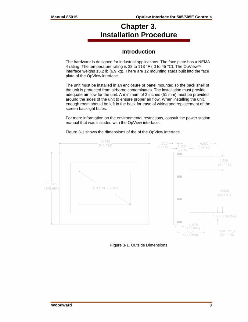
Introduction The hardware is designed for industrial applications. The face plate has a NEMA 4 rating. The temperature rating is 32 to 113 °F ( 0 to 45 °C). The OpView™ interface weighs 15.2 lb (6.9 kg). There are 12 mounting studs built into the face plate of the OpView interface. The unit must be installed in an enclosure or panel mounted so the back shell of the unit is protected from airborne contaminates. The installation must provide adequate air flow for the unit. A minimum of 2 inches (51 mm) must be provided around the sides of the unit to ensure proper air flow. When installing the unit, enough room should be left in the back for ease of wiring and replacement of the screen backlight bulbs. For more information on the environmental restrictions, consult the power station manual that was included with the OpView interface. Figure 3-1 shows the dimensions of the of the OpView interface.
Figure 3-1. Outside Dimensions

OpView Interface for 505/505E Controls Manual 85015
4 Woodward
Figure 3-2. Mounting Template
Communications The OpView has two communication ports (see Figure 2-1). Comm 1 port is for printer use, and comm 2 port is for communication with the 505 control. The OpView interface uses three communication standards; RS-232, RS-422, and RS-485. The communication standard used will be determine by the distance between the 505 control and the OpView interface. RS-232 communications should not be used if the distance between the devices is greater than 50 ft (15 m). RS-422 and RS- 485 communications can be used up to a distance of 4000 ft (1200 m). The following figures (3-3, 3-4, and 3-5) show the three wiring diagrams for the supported method of communications. The 505 control can be configured to use either port 1 or port 2 to communicate to the OpView interface. For more information on the 505 communication configurations, consult the control manual.
The jumpers used for communication terminations on the 505 control should be left at the factory settings.

Manual 85015 OpView Interface for 505/505E Controls
Woodward 5
Figure 3-3a. RS-232 Communications (DB9 connector)
Figure 3-3b. RS-232 Communications (DB25 connector)
OpView Interface for 505/505E Controls Manual 85015
6 Woodward
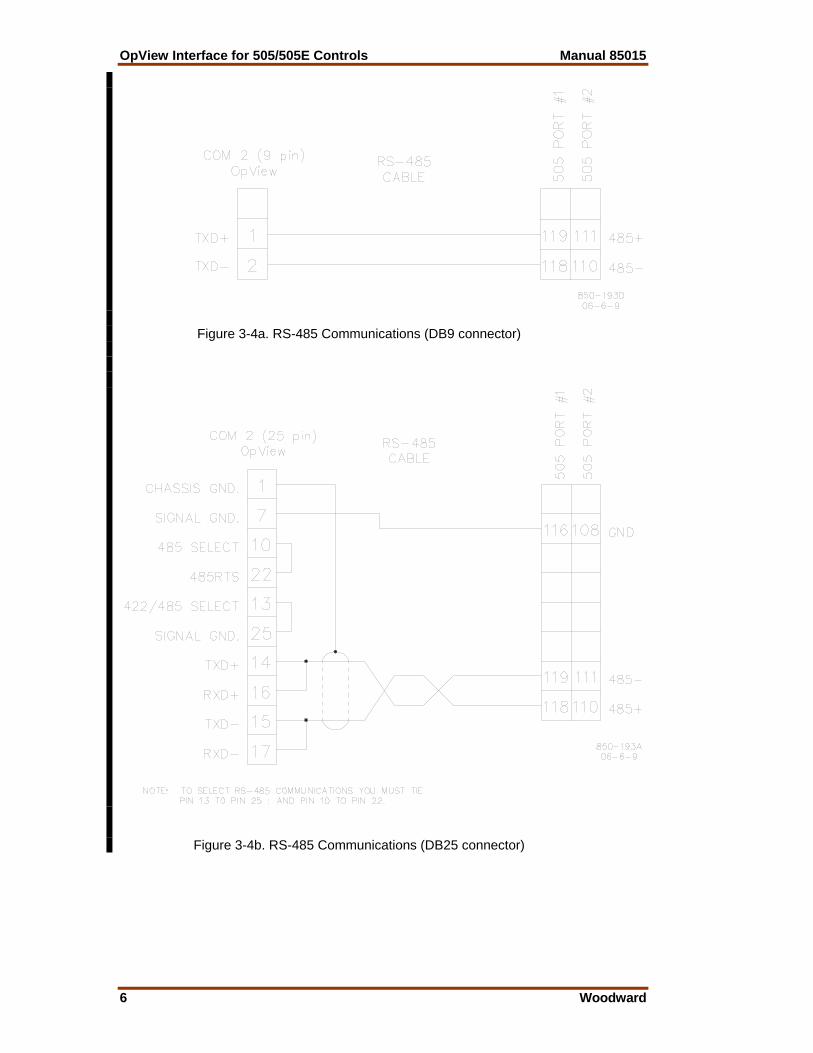
Figure 3-4a. RS-485 Communications (DB9 connector)
Figure 3-4b. RS-485 Communications (DB25 connector)

Manual 85015 OpView Interface for 505/505E Controls
Woodward 7
Figure 3-5a. RS-422 Communications (DB9 connector)
Figure 3-5b. RS-422 Communications (DB25 connector) The 505 control is programmed at the factory to continuously output data to the two communication ports and will not accept any commands from the communication ports. Before the OpView interface can be utilized, the communication port(s) have to be enabled in the 505 program (configure) mode. Refer to the 505 manual for information concerning the configuration of the controls communication ports.

OpView Interface for 505/505E Controls Manual 85015
8 Woodward
The settings of both Modbus ports of the 505 control are defaulted as follows. Modbus PORT 1 Protocol RTU Modbus Device Number 1 Communications Mode RS232 Baud Rate 19200 Stop Bits 1 Parity NONE Modbus PORT 2 Protocol RTU Modbus Device Number 2 Communications Mode RS232 Baud Rate 19200 Stop Bits 1 Parity NONE The communication settings of the OpView has been set to the following Protocol Type RTU Baud Rate 19200 Parity NONE Stop Bits 1 Port Number COMM 2 Device Number 1 The 505 program is defaulted to use port 1 to communicate with the OpView interface. If the settings for port 1 have changed or port 2 is the desired communication port, then the settings of the 505 will need to be changed to match the communication settings of the OpView interface. Printer Setup If a serial printer is to be used with the OpView interface to print out the alarm log, it must be connected to the OpView Comm 1 port.
Figure 3-6. Serial Printer Connection

Manual 85015 OpView Interface for 505/505E Controls
Woodward 9
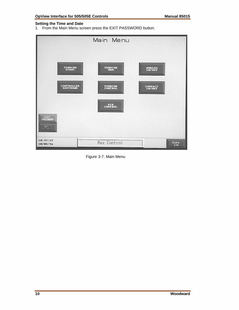
The printer must be configured for the following protocol settings: Baud Rate 9600 Parity NONE Data Bits 8 Stop Bits 1 Initial Setup Upon power up, the OpView interface will go into the Run Mode, and the first screen to appear will be the Main Menu. From the Run Mode the OpView interface can give commands to the 505 control and receive information from the 505 control. From the Main Menu screen, the operator can access any of the operational screens or the Alarm Log screen. The Main Menu allows access to the Alarm Log screen any time the unit is in the Run Mode. Access to the Application Manager and the Shell Menu is available from the Main Menu after the proper password is entered. While the Application Manager is being used to set the time and date, the OpView interface will continue to communicate with the 505 control. Exiting the Application Manager to the shell menu will stop communications. The OpView software has two different user levels: Supervisor and 505 User. The Supervisor (supvar) Level allows the OpView interface to be taken out of the Run Mode and access the Application Manager and Shell Menu. To change the any settings of the application manager or the shell menu, the OpView user level has to be changed to the Supervisor Level. The 505 User level allows full access to the Run Mode only. Both levels have complete access to the OpView Run Mode. The OpView interface will initialize in the 505 user level. When the set-up is complete, the user level may be changed to the 505 level to limit access to the Application Manager and the Shell Menu. The Run Mode is the normal operating mode for the unit. Exiting the Run Mode or the Application Manager and going into the Shell Menu stops communication between the unit and the 505 control. The Shell Menu should only be accessed to calibrate the touch screen. These procedures should be done at installation, and under normal operating procedures the OpView interface must stay in the Run Mode. The steps and screens for setting the time and date are listed below.
OpView Interface for 505/505E Controls Manual 85015
10 Woodward
Setting the Time and Date 1. From the Main Menu screen press the EXIT PASSWORD button.
Figure 3-7. Main Menu
Manual 85015 OpView Interface for 505/505E Controls
Woodward 11
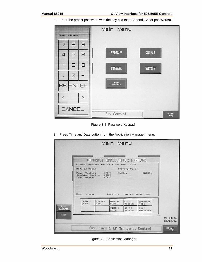
2. Enter the proper password with the key pad (see Appendix A for passwords).
Figure 3-8. Password Keypad 3. Press Time and Date button from the Application Manager menu.
Figure 3-9. Application Manager
OpView Interface for 505/505E Controls Manual 85015
12 Woodward
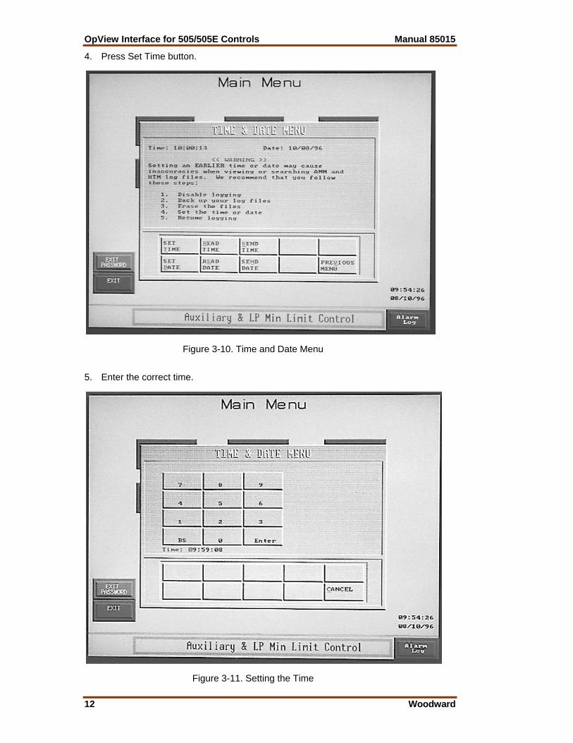
4. Press Set Time button.
Figure 3-10. Time and Date Menu 5. Enter the correct time.
Figure 3-11. Setting the Time

Manual 85015 OpView Interface for 505/505E Controls
Woodward 13
6. Press the Enter button. 7. Press Set Date button.
Figure 3-12. Setting the Date 8. Enter the correct date. 9. Press the Enter button. 10. Press Previous Menu button (see Figure 3-10). 11. Press Change User button from the Application Manager menu (see Figure
3- 9). 12. Enter the 505 user level password (see Appendix A for passwords). 13. Press Enter. 14. Press Go To Module button (see Figure 3-9). 15. The OpView interface will return to the Main Menu screen.
The OpView interface user level may be changed to 505 user level to limit access to the Application Manager and the Shell Menu after initial set-up.
Some of the options under the shell menu will erase the OpView program. The OpView interface will then have to be reprogrammed.

OpView Interface for 505/505E Controls Manual 85015
14 Woodward
Figure 3-13. Exit Interact
Figure 3-14. Shell Menu

Manual 85015 OpView Interface for 505/505E Controls
Woodward 15
Figure 3-15. Hardware Settings
Some of the options under the Shell Menu will erase the program in the OpView interface. The OpView interface will then have to be reprogrammed.
The other options in the Application Manager and the Shell Menu are explained in more detail in the hardware manual provided by the OpView hardware manufacture. Woodward strongly recommends that the customer exercise caution if any of the other options are used. The OpView hardware manual should be consulted for troubleshooting hardware faults and for performing hardware maintenance.
OpView Interface for 505/505E Controls Manual 85015
16 Woodward
Chapter 4. Operation
General Operating Procedures This chapter describes all the options and features that are available after the OpView™ interface is installed, powered up and communicating with a 505 control. This manual should not be used as an operational manual for the control. Refer to the manual that was included with the control for more information on the operation and different control functions of the 505 or 505E control. All normal control operations can be performed through the OpView interface. For safety reasons, overspeed testing and valve (actuator), calibration cannot be performed through the OpView interface. For a detailed description of the functions that are programmed refer to the manual that came with the 505 control. Main Menu The Main Menu screen will be the first screen that appears after power has been applied and the OpView interface has gone though self test, initialized the program, and is in the run mode. The are eight basic control screens available (nine screens with the 505E version). Turbine Start Screen The OpView interface has three separate start screens for the different start modes of the 505 control, Idle/Rated, Min Governor, and Auto Start Sequence. The operator has complete control of the start sequence. Controlled Shutdown Screen The operator has complete control of the 505 controlled shutdown sequence. Turbine Run Screen The Turbine Run screen allows the operator complete control of the turbine under normal operating conditions. This gives the operator control of the setpoints for speed and the other control functions that are configured. If the control is configured for a generator breaker status, and information needed for synchronization and or load sharing is displayed on this screen. The number of hours the turbine has been running since the last shutdown is also shown. When relays are configured for Modbus control then access is allowed to the Modbus relay control screen.

Manual 85015 OpView Interface for 505/505E Controls
Woodward 17
Modbus Relay Screen (available only from the Turbine Run screen) From the Modbus Relay Control screen, 505/505E relays that are configured for Modbus control can be energized and de-energized. The status of the Modbus relays are shown. Turbine Control Screen The Turbine Control screen has information concerning the setpoint and process of the control parameters that are configured. Enabling and disabling the various control functions and the remote setpoint for the different controlling functions can be performed from this screen. Direct entry of a setpoint is available from the Turbine Control screen. PID Control Screen The PID Control screen shows all 505/505E PID outputs. The setpoints of the configured functions can be raised and lowered. Enabling and disabling the control function(s) can be accomplished from this screen. The PID Control screen also shows the valve demand or KW signal and percentage of load if configured as a generator. Extraction Control Screen (505E version only) When the OpView interface is used with the 505E, there will be an additional screen for Extraction Control. This screen displays the HP and LP valve demands and allows pressure or speed priority selection. The extraction setpoint can be raised or lowered from this screen and extraction control can be enabled or disabled. Analog Input / Output Screen The Analog Input/Output screen displays each of the six analog inputs, six analog outputs and what they are configured for. This screen shows the actual value of the input or output in mA and in percentage. Contact Input / Output Screen The Contact Input/Output screen shows the status of all contact inputs and outputs. The configuration of the 12 configurable contact inputs and six configurable relays are displayed on this page. Additionally, this screen shows the status of the pre-configured inputs and outputs. Alarm Log Screen The Alarm Log screen lists the alarm and trip indications with the time of the event. The Alarm Log lists the time of an alarm or trip acknowledgement. Last trip indication is also displayed on this screen. If a printer is used, the printer can be turned on or off from this screen.

OpView Interface for 505/505E Controls Manual 85015
18 Woodward
Controlling Parameter On the bottom of all screens, except the Alarm Log screen, there will be status messages stating the controlling parameter . The alarm or trip indication is located at the bottom of each screen next to the controlling parameter message. The alarm indication will blink until the alarm is acknowledged If another alarm conditions happens, the alarm indication will start flashing again until acknowledged. Scaling Factors The OpView interface can use the Modbus scaling factor of the 505 control to provide decimal places on predefined analog values or to keep the analog values between -32767 and 32767, a Modbus limitation. The scaling factor depends upon the value sent across the Modbus link. The scaling factors used are 0.1, 1, 10, 100. A scale factor of 10 will automatically provide one decimal place for that value, scale factor of 100 provides two decimal places. The scaling factor is defaulted to 1 for the 505/505E controls. The scaling factor can be changed using the Service Mode of the 505/505E control. Refer to the 505/505E manual for detailed information concerning changing the scaling factors. Units The OpView will display the units of measure for the control functions configured when this option is configured in the 505 control Emergency Trip The Emergency Trip command button is displayed on all screens when the 505 control is configured to accept an emergency trip from the OpView interface. The 505 control’s Service Mode is used to enable the Emergency Trip button. Refer to volume two of the 505 manual for more information on this option. The 505 control is defaulted to not accept an emergency trip from the OpView interface. The OpView emergency trip utilizes a two step process to avoid accidental shutdowns. The following procedure explains the two step emergency trip. 1. Press the Emergency Trip button. 2. Press the second Emergency Trip button, within five seconds. 3. The 505 will shut down. The second button will appear above the screen title. After five seconds, the second button will disappear from the screen and the first step will have to be reinitiated.
Detailed Operating Procedures Main Menu The Main Menu screen will be the first screen that appears after power has been applied and the OpView interface has gone though self-test, initialized the program, and is in the Run Mode. The are eight basic control screens available (nine screens with the 505E version).

Manual 85015 OpView Interface for 505/505E Controls
Woodward 19
The main menu is shown in the following figures.
Figure 4-1. 505 Main Menu
Figure 4-2. 505E Main Menu

OpView Interface for 505/505E Controls Manual 85015
20 Woodward
The Main Menu lets the operator have a choice of selecting any one of eight different screens (nine screens with the 505E). The screens are Turbine Start, Controlled Shutdown, Turbine Run, Turbine Control, PID Control, Analog In/ Out, Contact In/Out, Alarm Log, and Extraction Control (if 505E). If the 505 control is configured to use the Local/Remote function, only the Main Menu will have a button to switch between local/remote. This button is located in the upper left hand corner of the Main Menu screen and is only visible if the control is configured for this function. The text of the button will change to let the operator know what the button will do when pressed again. The Local/Remote function is explained in volume 2 of the 505 or 505E manual. The Local/Remote function of the 505 control is used to allow the operator to lock out inputs from contact inputs and the Modbus ports. The 505 will not accept commands from the OpView if the control is in the Local Mode. The OpView will display LOCAL on all screens and all setpoint raise/lower, enable/disable, reset buttons, and shutdown button will no longer be visible. The Alarm Log is always available from the main menu. From all other screens the Alarm Log is available only when an alarm condition is present. Turbine Start Screen The Turbine Start screen displayed will be different depending upon the start sequence configured in the 505 or 505E control. All screens give the user complete control over the start sequence selected. Each start mode gives the user control of the valve limiter and the speed setpoint. Speed, speed setpoint, and setpoint raise and lower commands are available from the start screen. Valve demand and valve limiter position are shown in bar graph form. Valve limiter raise and lower commands can be entered from the start screens. All of the start screens have Reset and Run buttons which allow starting the turbine when all shutdowns have been cleared. Idle / Rated Start The idle/rated start allows the user to start the turbine and choose between idle speed or rated speed. Refer to the 505 control manual for the full functionality of the Idle / Rated start sequence Figure 4-3 shows the Idle/Rated start screen for the 505E with two speed sensors configured. When ready, press the Run button to initiate the start sequence. After the turbine has reached idle speed, pressing the Go to Rated button will raise the turbine speed to the rated setpoint. The Go To Idle button will ramp the speed setpoint to the Idle speed. When the speed setpoint is ramping to the idle setpoint or to rated speed setpoint the message “MOVING TO IDLE” or “MOVING TO RATED” will appear above the speed readout. If the control has been configured to use the critical speed band(s) the message “ TURBINE IN CRITICAL SPEED BAND USING CRITICAL RATE” will appear above the speed readout when the speed is in the critical band. The speed setpoint can be raised or lowered with the up arrow and down arrow keys. Using the Raise/Lower keys will cause the idle/rated start sequence to be aborted. The setpoint can be moved to idle or rated by using the Idle or Rated buttons.

Manual 85015 OpView Interface for 505/505E Controls
Woodward 21
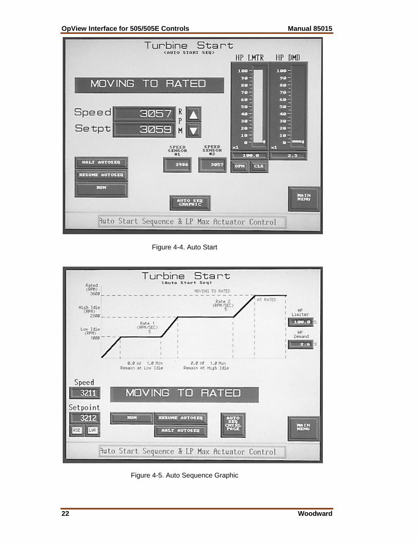
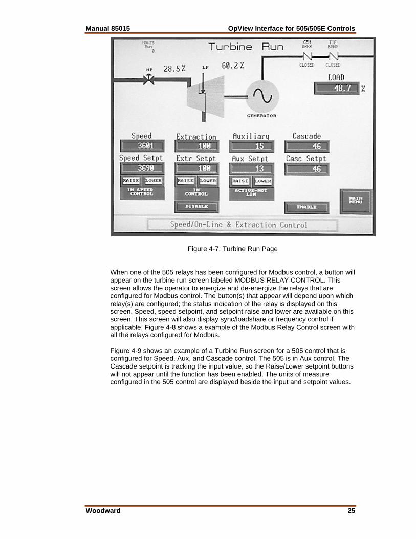
Figure 4-3. Idle/Rated The Speed Sensor Failure Override indication will go off when turbine speed is above the failed speed level, which was set when configuring the 505 control. The valve limiter is displayed using a bar graph with the value displayed under the bar graph. The limiter setpoint can be moved with the Open and Close buttons. The valve demand is displayed using a bar graph with the value displayed under the bar graph. This is the value output to the low signal select bus. Auto Start Sequence The auto start sequence has two separate screens that will display different information to a user concerning the start sequence. Status messages indicate where the control is in the sequence. The sequence may be halted at any time. If halted, the sequence can be resumed. The Auto Seq Graphic button allows an operator to select the other Auto Start Sequence screen. Figure 4-4 shows an example of the Auto Seq Cntrl screen. The Auto Seq Graphic screen of the auto start sequence displays a graph of the start sequence. The low idle, high idle, and rated setpoints are displayed. The hold times at high and low idle are shown in minutes. The rate of acceleration from low idle to high idle and from high idle to rated is displayed in RPM/SEC. Speed, speed setpoint, valve limiter setpoint, and the valve demand values are displayed. The user can go to the first Auto Sequence Screen with the Auto Seq Cntrl button. Figure 4-5 shows an example of the Auto Seq Graphic screen.
OpView Interface for 505/505E Controls Manual 85015
22 Woodward
Figure 4-4. Auto Start
Figure 4-5. Auto Sequence Graphic

Manual 85015 OpView Interface for 505/505E Controls
Woodward 23
Start Min Governor When ready to start the control, pressing the Run button will initiate the start sequence. The valve limiter ramps to 100% and the speed setpoint will ramp to Min Governor. An operator can use the up arrow and down arrow keys to raise and lower the speed setpoint between Min and Max Governor speeds. The Speed Sensor Failure Override indication will go off when the turbine speed is above the failed speed level, which was set when configuring the 505 control. The valve limiter is displayed using a bar graph with the value displayed under the bar graph. The limiter setpoint can be moved with the open and close buttons. The valve demand is displayed using a bar graph with the value displayed under the bar graph. This is the value output to the low signal select buss. Controlled Shutdown Screen A controlled shutdown can be initiated by pressing the Stop button. During the shutdown sequence, pressing the Abort button will abort the shutdown sequence. When the controlled shutdown is in progress, a message appears under the Abort button informing an operator that pressing the abort key will stop the shutdown sequence. Fig 4-6 is an example of the Controlled Shutdown screen.
Figure 4-6. Controlled Shutdown

OpView Interface for 505/505E Controls Manual 85015
24 Woodward
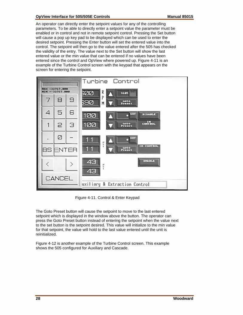
Turbine Run Screen The Turbine Run screen will display different options depending on the configuration of the 505 control. Features which are always available include the percentage the valve(s) are open, speed and the speed setpoint, and speed control status message. The hours run since the last shutdown is displayed in the upper left hand corner of the screen. The display readout will change to days after 120 hours. If there is a shutdown condition, the number of hours since the shutdown are displayed in the upper left hand corner of the screen. For each function configured the screen will display the actual input, the setpoint with Raise and Lower buttons, and Enable/Disable buttons. There is a status message indicating whether the function is enabled, active, in control, or in remote setpoint control. If a function is always enabled, such as the Auxiliary Control configured as a limiter, the enable/disable button for that function will not appear on the screen. The Setpoint Raise/Lower buttons will not be displayed on the screen if the setpoint is tracking the input until the function is enabled or the remote setpoint control is enabled. If the control is configured for a generator application, the status of the breakers are shown. When configured for a KW signal the load value is displayed as the kW input on the turbine run screen, if the KW signal fails, the displayed value will be the load percentage based on the valve position. The turbine graphic will change from a drawing of a turbine and generator to a drawing of a turbine and load depending on the configuration of the 505 control. If the 505 is configured for two actuators the second valve will appear on the screen. For extraction units the HP and LP valves are shown. If the sync or sync/loadshare function is configured in the 505 control, a readout showing the value of the input will be displayed on the turbine run screen. There will be an enable/disable button under the readout for to allow for synchronizing before breaker closure. After the utility and the gen breakers are closed, synchronizing will be inhibited and the enable/disable button will disappear. A Frequency Control Arm/Disarm button will appear on the turbine run screen if this option is configured in the 505 control. Refer to “Frequency Arm/Disarm” in the 505 manual for more details on this option. When the 505 control is configured for a compressor application and one of the control’s analog inputs is configured for first stage pressure, the Turbine Run screen will have a readout showing the value of the analog input. Figure 4-7 shows an example of a Turbine Run screen for an extraction turbine with auxiliary and cascade configured. The control has been configured for a generator application with the status of the breakers shown. The input and setpoint for Speed, Extraction, Auxiliary, and Cascade functions are displayed. Figure 4-7 shows the auxiliary control with the Raise/Lower setpoint buttons visible and no Enable/Disable button displayed. This is because the auxiliary is configured as a limiter and is always enabled.
Manual 85015 OpView Interface for 505/505E Controls
Woodward 25
Figure 4-7. Turbine Run Page When one of the 505 relays has been configured for Modbus control, a button will appear on the turbine run screen labeled MODBUS RELAY CONTROL. This screen allows the operator to energize and de-energize the relays that are configured for Modbus control. The button(s) that appear will depend upon which relay(s) are configured; the status indication of the relay is displayed on this screen. Speed, speed setpoint, and setpoint raise and lower are available on this screen. This screen will also display sync/loadshare or frequency control if applicable. Figure 4-8 shows a example of the Modbus Relay Control screen with all the relays configured for Modbus. Figure 4-9 shows an example of a Turbine Run screen for a 505 control that is configured for Speed, Aux, and Cascade control. The 505 is in Aux control. The Cascade setpoint is tracking the input value, so the Raise/Lower setpoint buttons will not appear until the function has been enabled. The units of measure configured in the 505 control are displayed beside the input and setpoint values.

OpView Interface for 505/505E Controls Manual 85015
26 Woodward
Figure 4-8. Modbus Relay Control
Figure 4-9. Turbine Run

Manual 85015 OpView Interface for 505/505E Controls
Woodward 27
Turbine Control Screen For each function configured this screen will display the actual input, setpoint with Raise and Lower buttons, and Enable/Disable buttons. There is a status message indicating if the function is enabled, active, in control, or in remote setpoint control. When the 505 control is configured for remote setpoint control. The value of the remote input will be shown and Enable and Disable buttons will be displayed on the turbine control screen. The Turbine Control screen is the only screen that gives the operator control of enabling and disabling the remote setpoint for each controlling function of the 505 control. Figure 4-9 is an example of the Turbine Control screen for a 505E control with Extraction, Auxiliary, and Cascade configured.
The Main Menu button is displayed in the upper left hand corner of the screen.
Figure 4-10. Turbine Control
OpView Interface for 505/505E Controls Manual 85015
28 Woodward
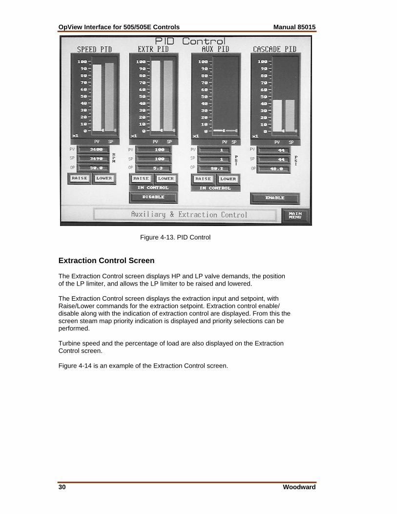
An operator can directly enter the setpoint values for any of the controlling parameters. To be able to directly enter a setpoint value the parameter must be enabled or in control and not in remote setpoint control. Pressing the Set button will cause a pop up key pad to be displayed which can be used to enter the desired setpoint. Pressing the Enter button will set the entered value into the control. The setpoint will then go to the value entered after the 505 has checked the validity of the entry. The value next to the Set button will show the last entered value or the min value that can be entered if no values have been entered since the control and OpView where powered up. Figure 4-11 is an example of the Turbine Control screen with the keypad that appears on the screen for entering the setpoint.
Figure 4-11. Control & Enter Keypad The Goto Preset button will cause the setpoint to move to the last entered setpoint which is displayed in the window above the button. The operator can press the Goto Preset button instead of entering the setpoint when the value next to the set button is the setpoint desired. This value will initialize to the min value for that setpoint, the value will hold to the last value entered until the unit is reinitialized. Figure 4-12 is another example of the Turbine Control screen. This example shows the 505 configured for Auxiliary and Cascade.

Manual 85015 OpView Interface for 505/505E Controls
Woodward 29
Figure 4-12. Turbine Control PID Control Screen The PID screen displays the various control loops which control the valve (s) output (s). The inputs and setpoints are scaled from zero to one hundred percent and shown using bar graphs. There are three values under the bar graph that show actual input, setpoint, and PID controller output. The Raise/Lower buttons are not displayed on the screen if the function is in remote setpoint control or the setpoint is tracking the input and the function is not enabled. Figure 4-13 shows an example of the PID screen for the 505E with Auxiliary and Cascade configured. With this screen, Auxiliary and Extraction PIDs are the controlling parameters. The bar graphs show inputs and setpoints. Buttons to raise and lower the setpoints are visible when the parameter is in control or enabled. The buttons will not be visible when the unit is in remote setpoint control or the setpoint is tracking the input and the function is not enabled. The Cascade setpoint is tracking the input and has not been enabled so the Raise and Lower Setpoint buttons are not visible. Once the Enable button has been pressed the Raise/Lower buttons will be visible and the Enable button will change to a Disable button. The units of measure are shown vertically along the side of the values under the bar graph.
OpView Interface for 505/505E Controls Manual 85015
30 Woodward
Figure 4-13. PID Control Extraction Control Screen The Extraction Control screen displays HP and LP valve demands, the position of the LP limiter, and allows the LP limiter to be raised and lowered. The Extraction Control screen displays the extraction input and setpoint, with Raise/Lower commands for the extraction setpoint. Extraction control enable/ disable along with the indication of extraction control are displayed. From this the screen steam map priority indication is displayed and priority selections can be performed. Turbine speed and the percentage of load are also displayed on the Extraction Control screen. Figure 4-14 is an example of the Extraction Control screen.

Manual 85015 OpView Interface for 505/505E Controls
Woodward 31
Figure 4-14. Extraction Control Analog In / Out Screen Figure 4-15 is an example of the Analog Input / Output screen. The configuration for each analog input and output is displayed. The value of the input or output is shown in percentage and milliamp values. Analog inputs are displayed in the engineering units, based on the 505 configuration. Turbine speed and speed setpoint value are displayed. The actuator(s) output is displayed in mA. The valve demand and limiter position is displayed on this screen.

OpView Interface for 505/505E Controls Manual 85015
32 Woodward
Figure 4-15. Analog In/Out Contact In / Out Screen Figure 4-16 shows an example of the Contact Input / Output screen. The configuration and status of each 505 contact input and relay is displayed. The configuration and status of the twelve configurable contact inputs is displayed on the left side of the screen. A closed indication indicates that input of the 505 control is being held high or a logic 1. An open indication means the input is being held low or a logic 0. The configuration and status of the six configurable relays is displayed on the right side of the screen. A de-energized indication means the coil of the relay is de-energized and the contacts are in the de-energized state. An energized indication means the coil of the relay is energized and the contacts are in the energized state. Consult the 505 manual or the template on the back of the 505 control for more information on the relays of the 505 control. The status of the two pre-configured contact outputs (shutdown and alarm), and the four pre-configured contact inputs (trip, reset, raise speed, and lower speed) are also displayed on this page.

Manual 85015 OpView Interface for 505/505E Controls
Woodward 33
Figure 4-16. Contact In/Out Alarm Log Screen
Figure 4-17. Alarm Log

OpView Interface for 505/505E Controls Manual 85015
34 Woodward
Figure 4-17 contains an example of the Alarm Log screen. The Event Log shows alarms and trips from the 505 control. Alarms or trips are listed with the time and date of the event. Alarm or trip status is displayed in the line between the time and the description of the event. This status lets the user know if the event has been acknowledged or not. If acknowledged, the time the event was acknowledged is then displayed. An asterisk next to the indication means the alarm or trip has not been acknowledged Once the alarm or trip has been cleared and a reset has been given to the control the indication will display “inactive”. The Clear button clears all inactive alarms/trips from the alarm log. The last trip condition is displayed on this screen. This indication will be updated when another trip condition occurs. The OpView Event Log can be printed to a serial printer. The printer must be connected to comm 1 port on the back of the OpView. Port settings: baud rate: 9600 parity: none data bits: 8 stop bit: 1 The Event Log is printed as it appears on the screen. The Event Log will print each time an alarm or trip occurs. Acknowledges and reset commands are also printed. Interact Alarm Log Here is an example of an Alarm Log print out. The title and header is printed each time the OpView is initialized in the Run Mode and the printer is turned on.
Application: 505 E
TIME DATE DESCRIPTION STATUS VALUE / USER 09:30:54 09/23/96 <<PRINTER ENABLED>> supvar 09:55:06 09/23/96 *Alarm Comm Link #1 Failed ACTIVE ALARM 09:56:04 09/23/96 Alarm Comm Link #1 Failed ACKNOWLEDGE supvar 09:58:04 09/23/96 Alarm Comm Link #1 Failed INACTIVE OFF
In the example there is a comm failure. The print out shows the time, date, the type of alarm, and alarm status. When the event is acknowledge, the time of the acknowledgement is printed and the asterisk next to the event is no longer printed. The current user level is also printed. The next line shows when the alarm condition was reset after the comm link error was corrected. Printer control and status are displayed in the lower left hand corner of the screen. If a printer is not connected to the OpView interface or the printer is malfunctioning the printer control must be in the off state.

Manual 85015 OpView Interface for 505/505E Controls
Woodward 35
Chapter 5. Service Options
Product Service Options If you are experiencing problems with the installation, or unsatisfactory performance of a Woodward product, the following options are available: • Consult the troubleshooting guide in the manual. • Contact the manufacturer or packager of your system. • Contact the Woodward Full Service Distributor serving your area. • Contact Woodward technical assistance (see “How to Contact Woodward”
later in this chapter) and discuss your problem. In many cases, your problem can be resolved over the phone. If not, you can select which course of action to pursue based on the available services listed in this chapter.
OEM and Packager Support: Many Woodward controls and control devices are installed into the equipment system and programmed by an Original Equipment Manufacturer (OEM) or Equipment Packager at their factory. In some cases, the programming is password-protected by the OEM or packager, and they are the best source for product service and support. Warranty service for Woodward products shipped with an equipment system should also be handled through the OEM or Packager. Please review your equipment system documentation for details. Woodward Business Partner Support: Woodward works with and supports a global network of independent business partners whose mission is to serve the users of Woodward controls, as described here:
• A Full Service Distributor has the primary responsibility for sales, service, system integration solutions, technical desk support, and aftermarket marketing of standard Woodward products within a specific geographic area and market segment.
• An Authorized Independent Service Facility (AISF) provides authorized service that includes repairs, repair parts, and warranty service on Woodward's behalf. Service (not new unit sales) is an AISF's primary mission.
• A Recognized Engine Retrofitter (RER) is an independent company that does retrofits and upgrades on reciprocating gas engines and dual-fuel conversions, and can provide the full line of Woodward systems and components for the retrofits and overhauls, emission compliance upgrades, long term service contracts, emergency repairs, etc.
• A Recognized Turbine Retrofitter (RTR) is an independent company that does both steam and gas turbine control retrofits and upgrades globally, and can provide the full line of Woodward systems and components for the retrofits and overhauls, long term service contracts, emergency repairs, etc.
A current list of Woodward Business Partners is available at www.woodward.com/support.

OpView Interface for 505/505E Controls Manual 85015
36 Woodward
Woodward Factory Servicing Options The following factory options for servicing Woodward products are available through your local Full-Service Distributor or the OEM or Packager of the equipment system, based on the standard Woodward Product and Service Warranty (5-01-1205) that is in effect at the time the product is originally shipped from Woodward or a service is performed: • Replacement/Exchange (24-hour service) • Flat Rate Repair • Flat Rate Remanufacture Replacement/Exchange: Replacement/Exchange is a premium program designed for the user who is in need of immediate service. It allows you to request and receive a like-new replacement unit in minimum time (usually within 24 hours of the request), providing a suitable unit is available at the time of the request, thereby minimizing costly downtime. This is a flat-rate program and includes the full standard Woodward product warranty (Woodward Product and Service Warranty 5-01-1205). This option allows you to call your Full-Service Distributor in the event of an unexpected outage, or in advance of a scheduled outage, to request a replacement control unit. If the unit is available at the time of the call, it can usually be shipped out within 24 hours. You replace your field control unit with the like-new replacement and return the field unit to the Full-Service Distributor. Charges for the Replacement/Exchange service are based on a flat rate plus shipping expenses. You are invoiced the flat rate replacement/exchange charge plus a core charge at the time the replacement unit is shipped. If the core (field unit) is returned within 60 days, a credit for the core charge will be issued. Flat Rate Repair: Flat Rate Repair is available for the majority of standard products in the field. This program offers you repair service for your products with the advantage of knowing in advance what the cost will be. All repair work carries the standard Woodward service warranty (Woodward Product and Service Warranty 5-01-1205) on replaced parts and labor. Flat Rate Remanufacture: Flat Rate Remanufacture is very similar to the Flat Rate Repair option with the exception that the unit will be returned to you in “like-new” condition and carry with it the full standard Woodward product warranty (Woodward Product and Service Warranty 5-01-1205). This option is applicable to mechanical products only.

Manual 85015 OpView Interface for 505/505E Controls
Woodward 37
Returning Equipment for Repair If a control (or any part of an electronic control) is to be returned for repair, please contact your Full-Service Distributor in advance to obtain Return Authorization and shipping instructions. When shipping the item(s), attach a tag with the following information: • return number; • name and location where the control is installed; • name and phone number of contact person; • complete Woodward part number(s) and serial number(s); • description of the problem; • instructions describing the desired type of repair. Packing a Control Use the following materials when returning a complete control: • protective caps on any connectors; • antistatic protective bags on all electronic modules; • packing materials that will not damage the surface of the unit; • at least 100 mm (4 inches) of tightly packed, industry-approved packing
material; • a packing carton with double walls; • a strong tape around the outside of the carton for increased strength.
To prevent damage to electronic components caused by improper handling, read and observe the precautions in Woodward manual 82715, Guide for Handling and Protection of Electronic Controls, Printed Circuit Boards, and Modules.
Replacement Parts When ordering replacement parts for controls, include the following information: • the part number(s) (XXXX-XXXX) that is on the enclosure nameplate; • the unit serial number, which is also on the nameplate.

OpView Interface for 505/505E Controls Manual 85015
38 Woodward
Engineering Services Woodward offers various Engineering Services for our products. For these services, you can contact us by telephone, by email, or through the Woodward website. • Technical Support • Product Training • Field Service Technical Support is available from your equipment system supplier, your local Full-Service Distributor, or from many of Woodward’s worldwide locations, depending upon the product and application. This service can assist you with technical questions or problem solving during the normal business hours of the Woodward location you contact. Emergency assistance is also available during non-business hours by phoning Woodward and stating the urgency of your problem. Product Training is available as standard classes at many of our worldwide locations. We also offer customized classes, which can be tailored to your needs and can be held at one of our locations or at your site. This training, conducted by experienced personnel, will assure that you will be able to maintain system reliability and availability. Field Service engineering on-site support is available, depending on the product and location, from many of our worldwide locations or from one of our Full-Service Distributors. The field engineers are experienced both on Woodward products as well as on much of the non-Woodward equipment with which our products interface. For information on these services, please contact us via telephone, email us, or use our website and reference www.woodward.com/support, and then Customer Support.
How to Contact Woodward For assistance, call one of the following Woodward facilities to obtain the address and phone number of the facility nearest your location where you will be able to get information and service.
Electrical Power Systems Facility --------------- Phone Number Australia ----------- +61 (2) 9758 2322 Brazil ------------- +55 (19) 3708 4800 China ------------ +86 (512) 6762 6727 Germany: Kempen --- +49 (0) 21 52 14 51 Stuttgart ----- +49 (711) 78954-0 India --------------- +91 (129) 4097100 Japan -------------- +81 (43) 213-2191 Korea--------------- +82 (51) 636-7080 Poland -------------- +48 12 618 92 00 United States----- +1 (970) 482-5811
Engine Systems Facility --------------- Phone Number Australia ----------- +61 (2) 9758 2322 Brazil ------------- +55 (19) 3708 4800 China ------------ +86 (512) 6762 6727 Germany: Stuttgart ----- +49 (711) 78954-0 India --------------- +91 (129) 4097100 Japan -------------- +81 (43) 213-2191 Korea--------------- +82 (51) 636-7080 The Netherlands - +31 (23) 5661111 United States----- +1 (970) 482-5811
Turbine Systems Facility --------------- Phone Number Australia ----------- +61 (2) 9758 2322 Brazil ------------- +55 (19) 3708 4800 China ------------ +86 (512) 6762 6727 India --------------- +91 (129) 4097100 Japan -------------- +81 (43) 213-2191 Korea--------------- +82 (51) 636-7080 The Netherlands - +31 (23) 5661111 United States----- +1 (970) 482-5811
You can also contact the Woodward Customer Service Department or consult our worldwide directory on Woodward’s website (www.woodward.com/support) for the name of your nearest Woodward distributor or service facility. For the most current product support and contact information, please refer to the latest version of publication 51337 at www.woodward.com/publications.

Manual 85015 OpView Interface for 505/505E Controls
Woodward 39
Technical Assistance If you need to telephone for technical assistance, you will need to provide the following information. Please write it down here before phoning: General Your Name Site Location Phone Number Fax Number Prime Mover Information Engine/Turbine Model Number Manufacturer Number of Cylinders (if applicable) Type of Fuel (gas, gaseous, steam, etc) Rating Application Control/Governor Information Please list all Woodward governors, actuators, and electronic controls in your system: Woodward Part Number and Revision Letter Control Description or Governor Type Serial Number Woodward Part Number and Revision Letter Control Description or Governor Type Serial Number Woodward Part Number and Revision Letter Control Description or Governor Type Serial Number If you have an electronic or programmable control, please have the adjustment setting positions or the menu settings written down and with you at the time of the call.

OpView Interface for 505/505E Controls Manual 85015
40 Woodward

Manual 85015 OpView Interface for 505/505E Controls
Woodward 41
Appendix. Password Information
General The OpView™ interface requires a password to change between the two different user levels, supvar and 505. The user levels are used to limit the access of unauthorized or untrained personnel from accessing functions in the supvar (supervisor) level. If only certain people are to know these passwords, remove this appendix and keep it in a separate place, apart from this manual.
Supvar Level Password The password for your OpView is: 1113 Press Exit Password. When the keypad is displayed, enter the password and then press the enter key to gain access to the supvar level.
505 Level Password The password for your OpView is: 505 Press Exit Password. When the keypad is displayed, enter the password and then press the enter key to gain access to the 505 level. The user level can also be changed from the application manager screen, by pressing Change User and inputting the appropriate password.

We appreciate your comments about the content of our publications.
Send comments to: [email protected]
Please reference publication 85015B.
PO Box 1519, Fort Collins CO 80522-1519, USA 1000 East Drake Road, Fort Collins CO 80525, USA Phone +1 (970) 482-5811 • Fax +1 (970) 498-3058
Email and Website—www.woodward.com
Woodward has company-owned plants, subsidiaries, and branches, as well as authorized distributors and other authorized service and sales facilities throughout the world.
Complete address / phone / fax / email information for all locations is available on our website.
2009/4/Fort Collins