Embed Size (px)
Citation preview
Optoboards dependence on Temperature
C. Gemme, T.Flickdetector meeting, April 2nd 2009
Motivations Test in SR1
thanks to K. Lantzsch, L.Masetti, J.Moss, S. Strandberg for helping in setting up the system
Conclusions

Opto Temperature dependence in 2008
• We have some experience of temperature dependence in the pit:1. In early August Opto BPR set to 3.5 bar (~-5C );
optoheater setting to 5C. Optoboards temperature ~5-10 C: Many problems in operating the detector! Precise
quantification is difficult as the optotuning procedure was also not optimized yet.
2. BOC Scans vs temperature settings on part of the detector (Sep 9/10): Only 6 PP0s all failing at 10C Optoheaters settings at ~10C-13C-16C-19C-22C Data not exactly what we need: 2D scans with some
optotuning in between potentially changing Viset, etc..
DECIDED TO REDO THE TEST IN SR1
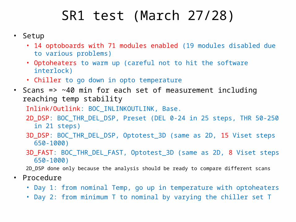
SR1 test (March 27/28)• Setup
• 14 optoboards with 71 modules enabled (19 modules disabled due to various problems)
• Optoheaters to warm up (careful not to hit the software interlock) • Chiller to go down in opto temperature
• Scans => ~40 min for each set of measurement including reaching temp stabilityInlink/Outlink: BOC_INLINKOUTLINK, Base.2D_DSP: BOC_THR_DEL_DSP, Preset (DEL 0-24 in 25 steps, THR 50-250
in 21 steps)3D_DSP: BOC_THR_DEL_DSP, Optotest_3D (same as 2D, 15 Viset steps
650-1000)3D_FAST: BOC_THR_DEL_FAST, Optotest_3D (same as 2D, 8 Viset steps
650-1000)2D_DSP done only because the analysis should be ready to compare different scans
• Procedure• Day 1: from nominal Temp, go up in temperature with optoheaters• Day 2: from minimum T to nominal by varying the chiller set T
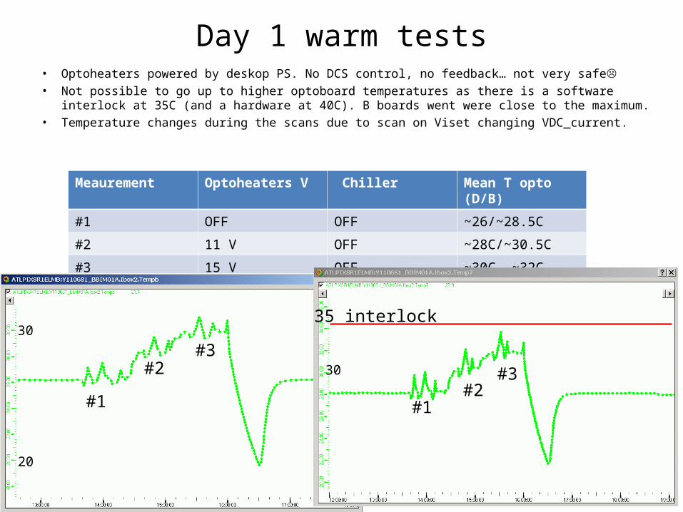
Day 1 warm tests• Optoheaters powered by deskop PS. No DCS control, no feedback… not very safe• Not possible to go up to higher optoboard temperatures as there is a software
interlock at 35C (and a hardware at 40C). B boards went were close to the maximum. • Temperature changes during the scans due to scan on Viset changing VDC_current.
Meaurement Optoheaters V Chiller Mean T opto (D/B)
#1 OFF OFF ~26/~28.5C
#2 11 V OFF ~28C/~30.5C
#3 15 V OFF ~30C, ~32C
30
20
30
35 interlock
#1
#2#3
#1#2
#3

Day2: cold tests
• Hygronometer to check the dew point (-15C inside the ~sealed Toothpix setup).
• Minimum temperature reachable by the chiller -23C and not very efficient thermal coupling with the optoloop.
Optsheaters
ChillerTemp (C)
T beforeopto
T opto (D/B)
1 OFF -23.4 -7.9 11/13
2 OFF -18 -4.3 13.1 /14.6
3 OFF -13 -0.6 15/17
4 OFF -8 3 17.5/18.9
5 OFF -3 5.3 19.1/20.4
6 OFF 5 9.5 21.7/23.0
7 OFF 13 14.4 24.9/26.5
8 OFF 20 19.2 28.6/ 29.2
9 OFF 25 22.2 30.2/31.3
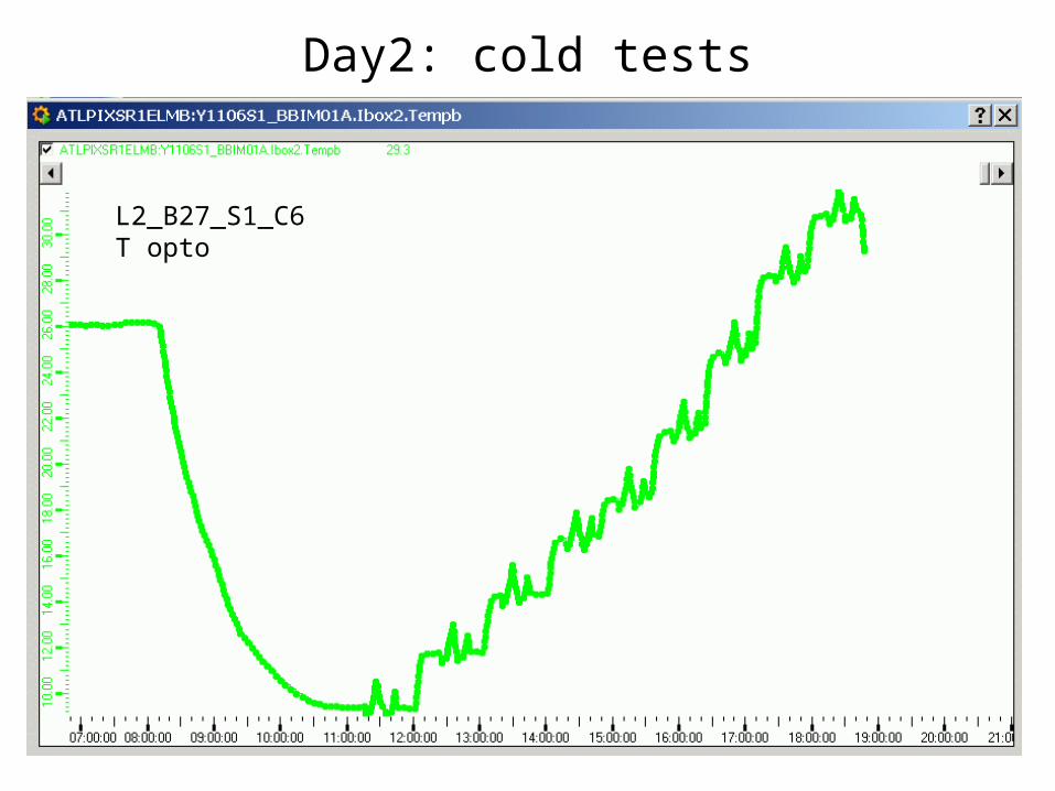
Day2: cold tests
L2_B27_S1_C6T opto
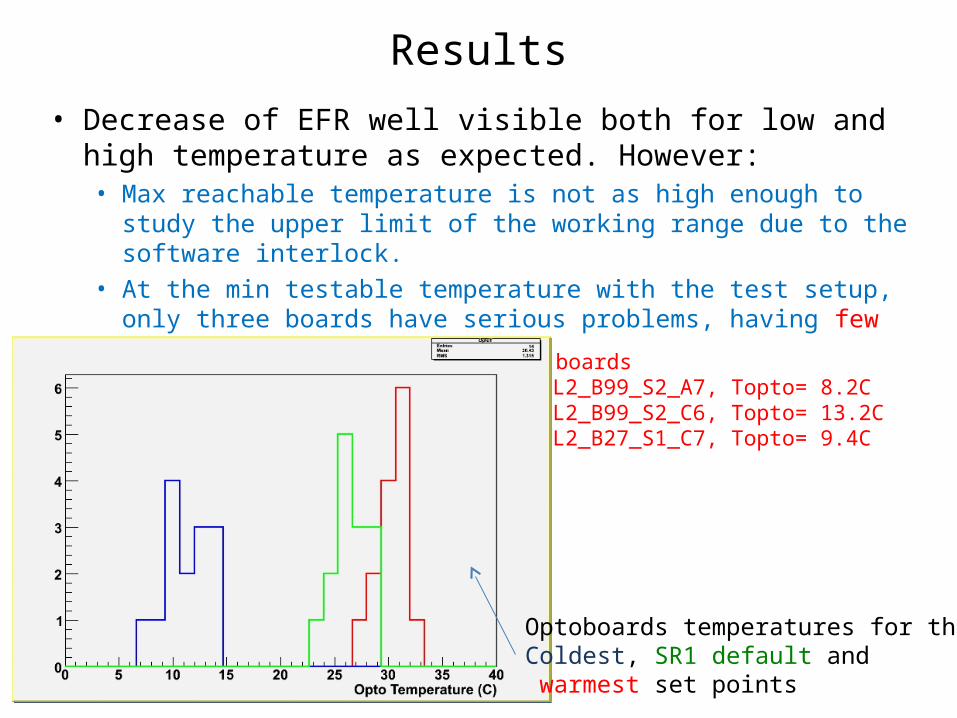
Results
• Decrease of EFR well visible both for low and high temperature as expected. However:• Max reachable temperature is not as high enough to study
the upper limit of the working range due to the software interlock.
• At the min testable temperature with the test setup, only three boards have serious problems, having few ch. each that misbehave. BAD boards
L2_B99_S2_A7, Topto= 8.2CL2_B99_S2_C6, Topto= 13.2CL2_B27_S1_C7, Topto= 9.4C
Optoboards temperatures for the Coldest, SR1 default and warmest set points
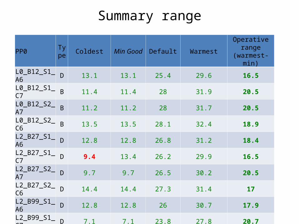
Summary range
PP0 Type Coldest Min Good Default Warmest Operative range
(warmest-min)
L0_B12_S1_A6 D 13.1 13.1 25.4 29.6 16.5
L0_B12_S1_C7 B 11.4 11.4 28 31.9 20.5
L0_B12_S2_A7 B 11.2 11.2 28 31.7 20.5
L0_B12_S2_C6 B 13.5 13.5 28.1 32.4 18.9
L2_B27_S1_A6 D 12.8 12.8 26.8 31.2 18.4
L2_B27_S1_C7 D 9.4 13.4 26.2 29.9 16.5
L2_B27_S2_A7 D 9.7 9.7 26.5 30.2 20.5L2_B27_S2_C6 D 14.4 14.4 27.3 31.4 17L2_B99_S1_A6 D 12.8 12.8 26 30.7 17.9
L2_B99_S1_C7 D 7.1 7.1 23.8 27.8 20.7
L2_B99_S2_A7 D 8.3 12.3 24.8 28.8 16.5L2_B99_S2_C6 D 13.5 19.5 26.7 31.7 12.2D1A_B01_S1 D 9.6 9.6 25.3 28.9 19.3D1A_B01_S2 D 9.6 9.6 25.9 29.8 20.2
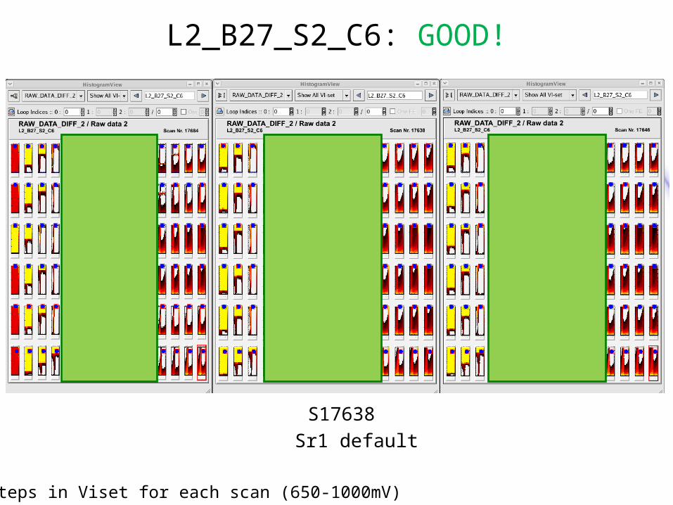
L2_B27_S2_C6: GOOD!
S17684 S17638 S17646
coldest Sr1 default warmest
15 steps in Viset for each scan (650-1000mV)

L2_B27_S1_C7: BAD
S17684 S17638 S17646
coldest Sr1 default warmest
15 steps in Viset for each scan (650-1000mV)

L2_B99_S2_A7: BAD
S17684 S17638 S17646
coldest Sr1 default warmest
15 steps in Viset for each scan (650-1000mV)

L2_B99_S2_C6: BAD
S17684 S17638 S17646
coldest Sr1 default warmest
Bad but only two modules enabled at all temperatures

The strange case of L2_B99_S2_C6_M6C
I/O Scan/Analysis
RX Current (mA) 3D_BOC Scan / comment T Opto
S17686/5817 0.04 S17684 - ok 13.3
S17687/5824 0.03 S17689 - not working 15.2
S17691/5828 0.38 S17693 - ok 17.4
S17695/5832 0.04 S17697 - Not working 19.2
S17699/5836 0.02 S17701 - Not working 20.6
S17703/5840 0.07 S17705 - Not working 22.7
S17707/5844 0.04 S17709 - Not working 24.9
S17711/5848 0.57 S17713 - ok 28.3
S17715/5856 0.02 S17717 - ok for the uppermost two Viset steps 30.7

Conclusions
Optoboards behaviour vs temperature has been studied in SR1:• Automatic analysis tools are in preparation to systematically analyze data.
• Inlink/oulink scan analysis is producing a first feedback of power vs temperature (Ron, Shih-Chieh, David)
• Maybe interesting to repeat the scans vs Viset (multiple scans varying Viset setting or a 2D in/outlink scan with outer loop on Viset), at constant temperature.
• 2D scan EFR analysis on-going (Su Yung, Tobias)
• It might be worth to further extend the temperature range at lower temperatures to check when the ‘good’ optoboards start misbehaving. Switch off part of the optoboards when at the lowest chiller temperature?
• L2_B99_S2_C6_M6C: power is not always null. To be checked with the powermeter on the BOC side: -> it is worth to measure the behaviour of the bad opto channels in the pit vs optoboard temperature to know more! (Bad opto channels: 2 no opto pin current, 1 no command received , 4 dark channels)
• It will be interesting to repeat the test on the full detector when the cooling will be back and then a full characterization of our detector optoboards will be available on a wider temperature range.
• Anyway this test is interesting to have some partial results for the opto note and to prepare tools for the full scale test.
Spares
• Cold, default, warm scans for all PP0s…

L0_B12_S1_A6_Link0
S17684 S17638 S17646
coldest Sr1 default warmest

L0_B12_S1_C7_Link0
S17684 S17638 S17646
coldest Sr1 default warmest
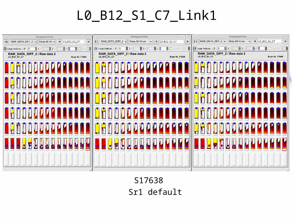
L0_B12_S1_C7_Link1
S17684 S17638 S17646
coldest Sr1 default warmest
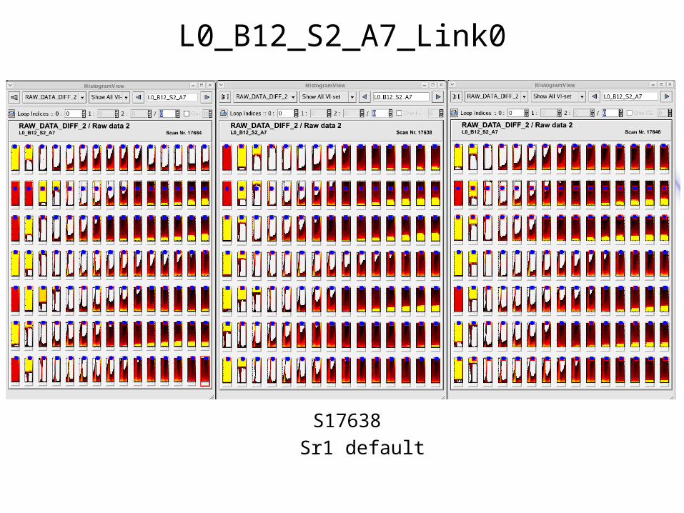
L0_B12_S2_A7_Link0
S17684 S17638 S17646
coldest Sr1 default warmest

L0_B12_S2_A7_Link1
S17684 S17638 S17646
coldest Sr1 default warmest
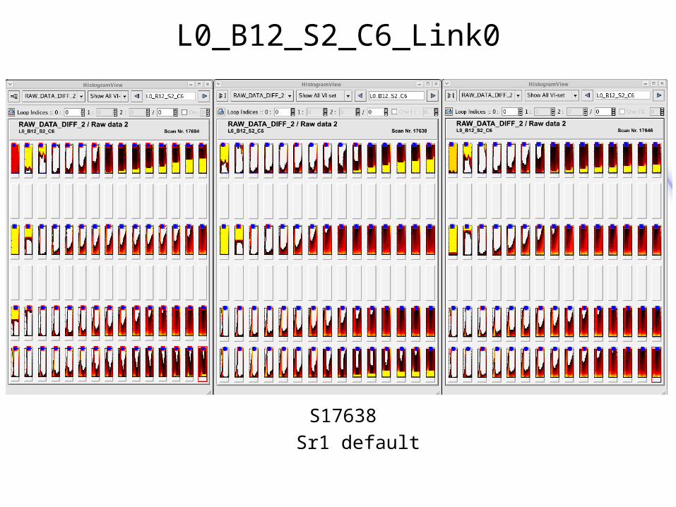
L0_B12_S2_C6_Link0
S17684 S17638 S17646
coldest Sr1 default warmest
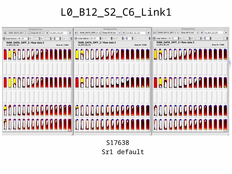
L0_B12_S2_C6_Link1
S17684 S17638 S17646
coldest Sr1 default warmest

L2_B27_S1_A6
S17684 S17638 S17646
coldest Sr1 default warmest

L2_B27_S2_A7
S17684 S17638 S17646
coldest Sr1 default warmest
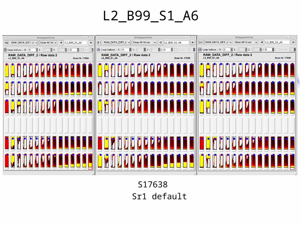
L2_B99_S1_A6
S17684 S17638 S17646
coldest Sr1 default warmest
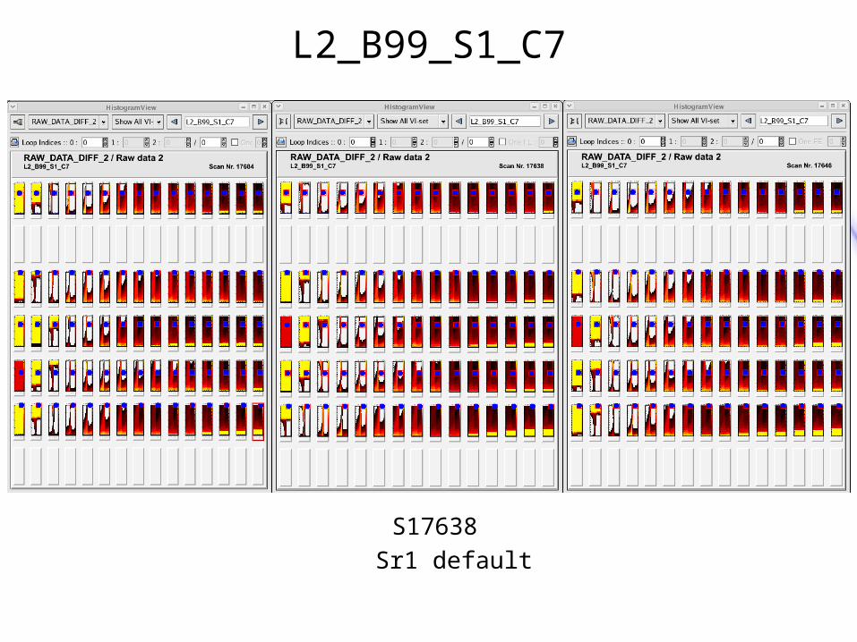
L2_B99_S1_C7
S17684 S17638 S17646
coldest Sr1 default warmest

D1A_B05_S1
S17684 S17638 S17646
coldest Sr1 default warmest

D1A_B05_S2
S17684 S17638 S17646
coldest Sr1 default warmest