Embed Size (px)
Citation preview

7/28/2019 OptiTex PDS User Manual
http://slidepdf.com/reader/full/optitex-pds-user-manual 1/727
SGS Digitize™, PDS™ & Grade™
User’s Manual

7/28/2019 OptiTex PDS User Manual
http://slidepdf.com/reader/full/optitex-pds-user-manual 2/727
SCANVEC GARMENT SYSTEMS SOFTWARE LICENSE AGREEMENT
This agreement gives you certain rights and duties regarding the Software Program, the User’s Guides and thecopy protection key (the “Key”) that you are licensing from Scanvec Garment Systems Ltd. (“Scanvec GarmentSystems”). The Software Program, the User’s Guides and the Key will be referred together here as the “Licensed
Materials”.
1. License grant and termination. Scanvec Garment Systems grants you personal, non-transferable, non-exclusivelicense to use the Licensed Materials for the ordinary purposes of your business. If you breach any terms of this
Agreement, this license will immediately terminate and you must promptly return the Licensed Materials toScanvec Garment Systems. The Licensed Materials are proprietary products of Scanvec Garment Systems, andScanvec Garment Systems retain title to and ownership of the Licensed Materials.
2. Scanvec Garment Systems copyright, etc. no copies or transfer, etc. You acknowledge that the LicensedMaterials are protected by copyrights held by Scanvec Garment Systems’ parent company. You acknowledgethat Licensed Materials embody trade secrets owned by Scanvec Garment Systems’ parent company. You may
not copy any part of the Licensed Materials for any purpose. You may not disassemble, decompile, reverseengineer or otherwise modify, tamper with or make changes to the Licensed Materials under any circumstances.You may not rent, lease, loan, assign or transfer the Licensed Material to any third party. You may not allow any
third party to use the Licensed Materials or to make copies of them. You may not use the Software Programwithout the Key. You may not emulate, duplicate, replace or modify the Key.
3. Warranty, disclaims, remedies. Scanvec Garment Systems warrants that the Media containing the Software
Program (the “CD’s”) are free from defects of materials and workmanship. SCANVEC GARMENT SYSTEMSDISCLAIM ALL OTHER EXPRESS AND IMPLIED WARRANTIES REGARDING THE CD’s AND THELICENSED MATERIALS. You agree that your only remedy for any breach of the above warranty will be that if you discover any defects in the CD’s within three months after receiving them, Scanvec Garment Systems will
replace the defective CD’s with non-defective CD’s.
4. No damages beyond Purchase Price. You agree that if, in connection with your use of the Licensed Materials,you incur direct or indirect injury of any kind, including injury to persons or property or lost profits, Scanvec
Garment Systems shall be liable to you only for the Product Price. In no event will Scanvec Garment Systems,
its stockholders, directors, officers or employees be liable to you for any damages, including lost profits or otherincidental or consequential damages arising out of your use or inability to use the Licensed Materials.
Copyright 2001, Scanvec Garment Systems
ALL RIGHTS RESERVE

7/28/2019 OptiTex PDS User Manual
http://slidepdf.com/reader/full/optitex-pds-user-manual 3/727
Table of Contents
Chapter 1: Introduction and Installation Procedures ______________________ 1
Welcome to OptiTex! ____________________________________________________ 1
How to Use This Book ___________________________________________________ 2
Package Contents _______________________________________________________ 3
Registration____________________________________________________________ 3
Help Services Provided __________________________________________________ 3
Technical Support ______________________________________________________ 4
Installing OptiTex_______________________________________________________ 5
Configuring OptiTex to Your Plotter _______________________________________ 9
Configuring Output Control Center (OCC) as output manger _________________ 12
Setting Up a Plotter ____________________________________________________ 15

7/28/2019 OptiTex PDS User Manual
http://slidepdf.com/reader/full/optitex-pds-user-manual 4/727
Chapter 2: Icons and Tool Bars_______________________________________ 17
The Tools _____________________________________________________________17
Grading Toolbar _______________________________________________________21
Equal X Grading (Ctrl + G + E) __________________________________________24
System Toolbar ________________________________________________________31
Insert Toolbar _________________________________________________________34
Edit Notch Dialog Box: __________________________________________________39

7/28/2019 OptiTex PDS User Manual
http://slidepdf.com/reader/full/optitex-pds-user-manual 5/727
The Edit Toolbar ______________________________________________________ 73
The Modify Toolbar ____________________________________________________ 85
The Darts Toolbar _____________________________________________________ 90
The General Toolbar ___________________________________________________ 95
The Advanced Toolbar_________________________________________________ 102
The Dimensional Toolbar ______________________________________________ 103
The Accessories Toolbar _______________________________________________ 107
The Template Basic Shapes Toolbar: _____________________________________ 123
The Template Toolbar: ________________________________________________ 124
7/28/2019 OptiTex PDS User Manual
http://slidepdf.com/reader/full/optitex-pds-user-manual 6/727
Chapter 3: File Menu ______________________________________________ 125
New (Ctrl+N): ________________________________________________________ 125
Open (Ctrl+O)________________________________________________________ 126Merge Style File ______________________________________________________ 128
History ______________________________________________________________ 131
File Finder ___________________________________________________________ 134
Save ________________________________________________________________ 144
Save As______________________________________________________________ 145
Digitize______________________________________________________________ 147
Digitizer Setup _______________________________________________________ 163
OptiTex Panel commands:______________________________________________ 166
Digitizer Dialog Box: __________________________________________________ 194
7/28/2019 OptiTex PDS User Manual
http://slidepdf.com/reader/full/optitex-pds-user-manual 7/727
Export to CAD/CAM files ______________________________________________197
Import from CAD/CAM Files ___________________________________________201
Layers Table Dialog Box: _______________________________________________212
Dictionary Dialog Box: _________________________________________________214
SGS Modulate ________________________________________________________217
Plot _________________________________________________________________219
Plotting Options for Graded Pieces_______________________________________243
Plotter Setup _________________________________________________________244
Print ________________________________________________________________246
Printer Setup _________________________________________________________248
Report to Excel and E-Mail utilities ______________________________________249
Exit (Alt+F4) _________________________________________________________253

7/28/2019 OptiTex PDS User Manual
http://slidepdf.com/reader/full/optitex-pds-user-manual 8/727
Chapter 4: Edit Menu _____________________________________________ 255
Undo (Ctrl+Z) ________________________________________________________255
Redo (Ctrl+Y) ________________________________________________________255
Cut Current Piece (Ctrl+X) _____________________________________________255
Copy Pieces __________________________________________________________256
Paste Piece (Ctrl+V) ___________________________________________________257
Copy/Paste Internals___________________________________________________258
Clear Selected Pieces___________________________________________________258
Clear Selected Piece ___________________________________________________259
Replace Old: _________________________________________________________259
Remove Current ______________________________________________________260
Make New ___________________________________________________________260Move Base Line _______________________________________________________261
Delete Piece (Del)______________________________________________________263
Attributes (Enter) _____________________________________________________265
Add Relative _________________________________________________________268
Align Points __________________________________________________________274
Round Corner ________________________________________________________275
Extend Internal _______________________________________________________276
Segment _____________________________________________________________277
Make Pieces __________________________________________________________283
Video________________________________________________________________285

7/28/2019 OptiTex PDS User Manual
http://slidepdf.com/reader/full/optitex-pds-user-manual 9/727
Chapter 5: Piece Menu_____________________________________________ 287
Info (Ctrl + I) ________________________________________________________ 287
Global Info __________________________________________________________ 295
Style Area and Perimeter Values Dialog Box_______________________________ 297
Global Change Internals _______________________________________________ 299
Global Notch Grading _________________________________________________ 300
Order of Internals_____________________________________________________ 301
Modify ______________________________________________________________ 301
Rotate_______________________________________________________________ 301
To Rotate the Baseline: ________________________________________________ 303
Flip Horizontal _______________________________________________________ 305
Flip Vertical _________________________________________________________ 305Mirror ______________________________________________________________ 306
Scale and Shrink______________________________________________________ 308
Optimize Cutter Ordering______________________________________________ 311
Points Cleanup _______________________________________________________ 312
Set (0,0) Point ________________________________________________________ 314
Start Point ___________________________________________________________ 314
Base Parallel to Segment _______________________________________________ 315
Make New Base Line __________________________________________________ 317Guideline Parallel _____________________________________________________ 318
Seam________________________________________________________________ 318
Reseam (F6)__________________________________________________________ 319
Update Notches _______________________________________________________ 320

7/28/2019 OptiTex PDS User Manual
http://slidepdf.com/reader/full/optitex-pds-user-manual 10/727
Digitize, PDS & Grade Manual336
Work on Seam (F5) ____________________________________________________320
Switch all Pieces to Cut (F5 + Ctrl) _______________________________________322
Switch all Pieces to Sew (F5 + Shift) ______________________________________322
Unseam______________________________________________________________322
Walk ________________________________________________________________323
Switch Direction (F11) _________________________________________________326
Notch Both (F12) ______________________________________________________327
Notch Stationary (F12 + Ctrl) ___________________________________________327
Notch Moving (F12 + Shift) _____________________________________________327
Fabric and Stripes _____________________________________________________327
Fabric Pattern ________________________________________________________328
Relate Piece to Stripes__________________________________________________332
Set Group____________________________________________________________334Ungroup _____________________________________________________________334

7/28/2019 OptiTex PDS User Manual
http://slidepdf.com/reader/full/optitex-pds-user-manual 11/727
Chapter 6: Grading Menu __________________________________________ 335
Stack Point___________________________________________________________336
Load Sizes ___________________________________________________________337
Reshape Variation Grading _____________________________________________338
Copy Grading (Ctrl + G, C) _____________________________________________339
Relative (Ctrl + G, R) __________________________________________________339
Paste Grading (Ctrl + G, P) _____________________________________________340
Paste X Grading (Ctrl + G, X) ___________________________________________340
Paste Y Grading (Ctrl + G, Y) ___________________________________________340
Paste Around (Ctrl + G, A) _____________________________________________340
Flip X Grading (Ctrl + G, F) ____________________________________________341
Flip Y Grading (Ctrl + G, L) ____________________________________________341
Equal X Grading (Ctrl + G, E) __________________________________________341
Equal Y Grading (Ctrl + G, Q) __________________________________________342
Zero Grade (Ctrl + G, Z) _______________________________________________342
Zero X Grade (Ctrl + G, N) _____________________________________________343
Zero Y Grade (Ctrl + G, O) _____________________________________________343
Sizes (Ctrl + G, S) _____________________________________________________344
Change Size Order ____________________________________________________347
Base Size_____________________________________________________________347
Sizes Variation: _______________________________________________________348
Graded Nest __________________________________________________________352
Grade Proportional____________________________________________________354
7/28/2019 OptiTex PDS User Manual
http://slidepdf.com/reader/full/optitex-pds-user-manual 12/727
Chapter 6: Grading Menu __________________________________________ 335
Stack Point___________________________________________________________336
Load Sizes ___________________________________________________________337
Reshape Variation Grading _____________________________________________338
Copy Grading (Ctrl + G, C) _____________________________________________339
Relative (Ctrl + G, R) __________________________________________________339
Paste Grading (Ctrl + G, P) _____________________________________________340
Paste X Grading (Ctrl + G, X) ___________________________________________340
Paste Y Grading (Ctrl + G, Y) ___________________________________________340
Paste Around (Ctrl + G, A) _____________________________________________340
Flip X Grading (Ctrl + G, F) ____________________________________________341
Flip Y Grading (Ctrl + G, L) ____________________________________________341
Equal X Grading (Ctrl + G, E) __________________________________________341
Equal Y Grading (Ctrl + G, Q) __________________________________________342
Zero Grade (Ctrl + G, Z) _______________________________________________342
Zero X Grade (Ctrl + G, N) _____________________________________________343
Zero Y Grade (Ctrl + G, O) _____________________________________________343
Sizes (Ctrl + G, S) _____________________________________________________344
Change Size Order ____________________________________________________347
Base Size_____________________________________________________________347
Sizes Variation: _______________________________________________________348
Graded Nest __________________________________________________________352
Grade Proportional____________________________________________________354

7/28/2019 OptiTex PDS User Manual
http://slidepdf.com/reader/full/optitex-pds-user-manual 13/727
Chapter 7: Pleats Menu ____________________________________________ 371
Add Pleat Lines ______________________________________________________371
Add Pleat By Angle ___________________________________________________371
Remove Pleat Lines ___________________________________________________372
Create Box or Knife ___________________________________________________372

7/28/2019 OptiTex PDS User Manual
http://slidepdf.com/reader/full/optitex-pds-user-manual 14/727
Chapter 8: Darts Menu_____________________________________________ 373
Open Dart ___________________________________________________________373
Open Multiple Darts __________________________________________________373
Create Dart __________________________________________________________374
Edit Dart ____________________________________________________________375
Remove Darts ________________________________________________________375
Copy Darts __________________________________________________________375
Paste Darts __________________________________________________________376
Rotate Dart to Point ___________________________________________________376
Rotate Around Center _________________________________________________377
Fix Darts ____________________________________________________________378
Reform Dart _________________________________________________________379

7/28/2019 OptiTex PDS User Manual
http://slidepdf.com/reader/full/optitex-pds-user-manual 15/727
Chapter 9: Design Menu ___________________________________________ 381
Create Parallel________________________________________________________381
Cut Parallel __________________________________________________________383
Segment Length_______________________________________________________384
Hole to Piece / Piece to Hole _____________________________________________387
Point Connection______________________________________________________388
Equal Segments _______________________________________________________390
Custom Fit ___________________________________________________________392
Custom fit tools _______________________________________________________398
Industrial Fabrics _____________________________________________________405
Hole By measure ______________________________________________________408
Create Parallel Cutting_________________________________________________410
Scatter Pieces_________________________________________________________411
Unscatter Pieces ______________________________________________________411
Arrange For Plot______________________________________________________411

7/28/2019 OptiTex PDS User Manual
http://slidepdf.com/reader/full/optitex-pds-user-manual 16/727
Chapter 10: Template Menu_________________________________________ 413
Open Library_________________________________________________________413
Add To Library_______________________________________________________415
Save As______________________________________________________________416
Choose ______________________________________________________________417
Primitive Tools Bar: ___________________________________________________418

7/28/2019 OptiTex PDS User Manual
http://slidepdf.com/reader/full/optitex-pds-user-manual 17/727
Chapter 11: View Menu ____________________________________________ 421
Template Window_____________________________________________________421
Screen Coordinates____________________________________________________421
Rulers _______________________________________________________________422
Pieces Bar____________________________________________________________422
Piece in one scale______________________________________________________423
Piece List ____________________________________________________________423
Piece Attributes _______________________________________________________424
Bubble Info __________________________________________________________427
Colors by Mode_______________________________________________________427
Base Only (F4)________________________________________________________429
Show Seam (Ctrl + F6) _________________________________________________429
Grading Table ________________________________________________________429
Grading Rules Library_________________________________________________429
Compare Length ______________________________________________________430
Calculator ___________________________________________________________434
Tool Bars ____________________________________________________________435
Status Bar ___________________________________________________________438

7/28/2019 OptiTex PDS User Manual
http://slidepdf.com/reader/full/optitex-pds-user-manual 18/727
Chapter 12: Options Menu __________________________________________ 439
Snap and Selection ____________________________________________________439
Draft Setup __________________________________________________________440
Grid and Stripes ______________________________________________________443
Colors and Line Types _________________________________________________444
Fonts________________________________________________________________447
Working Units ________________________________________________________447
Grading Manually by Edit Tool _________________________________________450
Open Move Point Dialog _______________________________________________450
Open Move Piece Dialog________________________________________________451
Open Create Dialog____________________________________________________451
Auto Reseam _________________________________________________________451
Auto Update Notches __________________________________________________452
Lock Piece (F3) _______________________________________________________452
Preferences___________________________________________________________453

7/28/2019 OptiTex PDS User Manual
http://slidepdf.com/reader/full/optitex-pds-user-manual 19/727
Chapter 13: Help Menu ____________________________________________ 459
Index (F1)____________________________________________________________459
Keyboard Map _______________________________________________________459
Scenario (Ctrl + F1) ___________________________________________________460
Using Help ___________________________________________________________460
Check Plug Protection _________________________________________________460
SGS on Line__________________________________________________________461
Tip of the Day ________________________________________________________461
About OptiTex PDS ___________________________________________________461
Send File_____________________________________________________________462
How to Contact SGS ___________________________________________________464
7/28/2019 OptiTex PDS User Manual
http://slidepdf.com/reader/full/optitex-pds-user-manual 20/727
Chapter 14: Using the Mouse________________________________________ 465
Right Mouse Button ___________________________________________________465
Select Tool ___________________________________________________________466
Edit _________________________________________________________________467
Insert _______________________________________________________________468
Tools ________________________________________________________________469
Zoom _______________________________________________________________470
Transform ___________________________________________________________471
Move Base Line _______________________________________________________473
Delete _______________________________________________________________473
Attribute ____________________________________________________________473
Segment _____________________________________________________________474
Grading _____________________________________________________________475

7/28/2019 OptiTex PDS User Manual
http://slidepdf.com/reader/full/optitex-pds-user-manual 21/727
Chapter 15: Keyboard Commands ____________________________________ 477
SGS Keys commands __________________________________________________477
Cursor Movement Keys ________________________________________________480
Dialog Box Keys ______________________________________________________480
Editing Keys _________________________________________________________481
Help Keys____________________________________________________________481
System Keys__________________________________________________________482
Text Selection Keys____________________________________________________482
keyboard shortcuts ____________________________________________________483
PDS ShortCut Keys____________________________________________________487

7/28/2019 OptiTex PDS User Manual
http://slidepdf.com/reader/full/optitex-pds-user-manual 22/727
Chapter 16: Digitizer Installation ____________________________________ 491
Installing the Numonics AccuGrid _______________________________________491
Configuring the GTCO Calcomp Drawing Board 3 Digitizer _________________495
Installing the Altek Digitizer For Use With SGS Software ___________________496
Installing the GTCO Roll Up Digitizer For Use In SGS software ______________502
Installing the SummaSketch II For Use In the SGS software _________________507
Installing the Summagraphic LCL Digitizer For Use In SGS _________________511
software _____________________________________________________________511
Installing the GTCO 5A DigiPad Digitizer For Use In SGS software___________516
Installing the MicroGrid IV Digitizer For Use In SGS software_______________521
Installing the MicroGrid II Digitizer For Use In SGS software _______________526
Installing the Summagraphic 4 Button Digitizer For Use In SGS software ______530
Installing the SummaSketch Professional Digitizer For Use In SGS software____534
Digitizer Manufacturers _______________________________________________539

7/28/2019 OptiTex PDS User Manual
http://slidepdf.com/reader/full/optitex-pds-user-manual 23/727
Chapter 17: Output Devices Installation_______________________________ 541
Installing Algotex Plotters with SGS Software _____________________________ 541
Hewlett Packard 600 or 700 Ink Jet Plotter _______________________________ 544
Hewlett Packard 750C Ink Jet Plotter____________________________________ 551
Configuring the Hewlett Packard Draftmaster II Plotter ____________________ 560
Ioline 28 Plotter ______________________________________________________ 568
Ioline 600 Plotter _____________________________________________________ 578
Ioline Studio Plotter___________________________________________________ 588
Ioline Stylist Plotter ___________________________________________________ 597
Configuring the Ioline Summit Plotter For Use With SGS Software ___________ 605
Plotter Technology Plotter _____________________________________________ 619
Calcomp TechJet 720 Plotter ___________________________________________ 626Gerber AP300 and AP310 Plotters_______________________________________ 632
Gerber AP700 Plotter _________________________________________________ 637
NovaJet Plotter_______________________________________________________ 642
Numonics Design Partner 9000 Plotter ___________________________________ 650
Summagraphic HighPlot 7100/7200 Plotter _______________________________ 657
Lectra plotter ________________________________________________________ 664
Configuring the Cutting Edge Cutter ____________________________________ 669
Eastman Cutter ______________________________________________________ 673
Configuring the Gerber Cutter S3250 ____________________________________ 677
Configuring the Gerber Cutter S-91 _____________________________________ 679
Configuring the Gerber Cutter S-93 _____________________________________ 682

7/28/2019 OptiTex PDS User Manual
http://slidepdf.com/reader/full/optitex-pds-user-manual 24/727
Glossary Terms ___________________________________________________ 685
7/28/2019 OptiTex PDS User Manual
http://slidepdf.com/reader/full/optitex-pds-user-manual 25/727
Chapter 1: Introduction and Installation Procedures 1
Chapter 1: Introduction and Installation Procedures
Welcome to OptiTex!
OptiTex is your complete software solution for computerized pattern design,
grading and marker making. It was created specifically for the manufacturer of the apparel, transportation interiors, upholstery and sewn products industries.
OptiTex’s powerful CAD tools enable you to draft pattern scratch or modify
existing pattern quickly and accurately. Simply import a pattern from your
favorite CAD/CAM program, create a new pattern using OptiTex’s freehanddesign tools or utilize OptiTex’s unique digitizing capabilities.
With OptiTex’s digitizing function, your pattern appears on your computer
screen as you digitize. If you make a mistake, simply erase it with the click of
a button. The OptiTex digitizing system is designed to work the way you want
to work. You can enter piece perimeters first, then enter notches, internals andother piece information later. It’s quick, easy and compatible with industry
standard digitizers.
Once your patters have been created and entered, OptiTex provides a
multitude of interactive editing tools. The most commonly used design andediting tools are represented as icons in the OptiTex toolbar so you can access
commands with the click of a mouse; there’s no need to navigate through a
series of pull down menus. Add or remove different types of notches, createdarts, add seam allowances pleats and buttons and view everything on screen
as you are working.
Add, move or delete points of a pattern, or move entire section of a pattern to
quickly lengthen or shorten pieces. And obtaining measurement has neverbeen easier. Whether you’re measuring vertically, horizontally, diagonally or
between pattern pieces, OptiTex’s measuring tool is as easy to use your own
tape measure.

7/28/2019 OptiTex PDS User Manual
http://slidepdf.com/reader/full/optitex-pds-user-manual 26/727
Digitize, PDS & Grade Manual2
OptiTex Makes grading pattern pieces quick, simple and automatic is just as
interactive as the editing process. Grade any pattern, point by point or globallyaccording to previously stored rules. OptiTex enable you to witness the results
immediately on screen. With OptiTex , it’s easy to create your own rule
libraries, add new rules or remove old ones. You can even grade internals such
as notches, dart, pleats, buttons and lines.
When it comes to marker making, OptiTex provides both manual andautomatic nesting capabilities to help you design markers quickly and
efficiently. In addition, OptiTex gives you the flexibility to change order
quintets, substitute size, change marker dimensions and additional patterns toyour marker from other styles. Match your pattern piece to specific locations
on your striped, plaid or printed materials.
With the extensive training and knowledgeable technical support services we
offer, we are confident you will find OptiTex to be most users Friendly
production tool you have experienced.
Thank you choosing OptiTex.
How to Use This Book
This manual is design to mirror your computer interface. The chapters arebased on the pull down menus and tool icons. To find information in this book,
use the index, table file, which allows you to view, print or save pertinent
information.
The remainder of this chapter is dedicated to explaining the different training
and technical support services SGS offer. Lastly, we offer completeinstallation directions with pictures.
Feel confident knowing that you not only purchased the most complete
software package for computerized pattern design, grading and marker
making, but also that SGS will continue to support you in every way we can.

7/28/2019 OptiTex PDS User Manual
http://slidepdf.com/reader/full/optitex-pds-user-manual 27/727
Chapter 1: Introduction and Installation Procedures 3
Package Contents
Security Lock
** VERY IMPORTANT** OptiTex will not operate without the Security
Lock!
Scanvec Garment Systems (SGS) will replace your CD if it is lost, but WILLNOT replace lost or stolen Security Lock. If the Security lock becomes
defective it will be replaced, but only after it has been returned to SGS. If you
must return the security lock, the package should be insured.
CD
The OptiTex Program Disk.
Documentation
OptiTex Manual and Lesson Plans
Registration
Before you begin, send in the Product Registration card to register yourself as
an owner of OptiTex. This card can be faxed or mailed to the address on the
card.
As a registered owner, you’ll be informed of updates, upgrades and trainingseminars; you’ll be on the mailing list for technical bulletins and product
information.
Help Services Provided
SGS offers extensive customer service. Below are the operational support
services available to you as a Registered OptiTex user.

7/28/2019 OptiTex PDS User Manual
http://slidepdf.com/reader/full/optitex-pds-user-manual 28/727
Digitize, PDS & Grade Manual4
Technical Support
Our US and Canada Technical Support department will provide assistance for
problems of a technical nature. If you are having problems printing or plotting,for example, technical support will assist you.
When calling for technical support, please be at your computer with the
following information:
• OptiTex Version Number.
• OptiTex Security Lock # (listed on the lock).
• Detailed description of the problem, including exact wording of any error messages.
Technical Support offices
USATel.: 610-521-5970 Toll free: (US & Canada) 877 RING OPTI
Fax: 610-521-1564
ISRAELTel.: 972-3-904-9979
Fax: 972-3-904-2710
Internet
Messages can be sent via Internet to our support at the following address:
E-Mail Technical Support: [email protected]
E-Mail Sales & Marketing: [email protected] Page
http://www.optitex.com

7/28/2019 OptiTex PDS User Manual
http://slidepdf.com/reader/full/optitex-pds-user-manual 29/727
Chapter 1: Introduction and Installation Procedures 5
Installing OptiTex
Before you run the installation program for OptiTex, make sure your computer
meets the minimum requirements to run the software.
OptiTex Requirements
Pentium or better processor
16 MB of RAM
Microsoft Windows ™ 95
Hard Drive with 150 MB of free disk space
Microsoft mouse or other compatible pointing device
SVGA 15’’ monitor running at resolution 800X600, 256 colors,
1 parallel port, 1 serial port
Recommended Equipment
Pentium II – 350 or better processor
64 MB of RAM
Microsoft Windows ™ 95 or Windows 98 or Windows NT
Hard Drive with 150 MB of free disk space
Microsoft mouse or other compatible pointing device
AGP display card with 4 MB of memory

7/28/2019 OptiTex PDS User Manual
http://slidepdf.com/reader/full/optitex-pds-user-manual 30/727
Digitize, PDS & Grade Manual6
17’’ monitor running at resolution 1024X768, 256 colors,
1 parallel port, 2 serial ports
USB port
SGS recommends using a Bus mouse if you intend to install a serial plotter ordigitizer, since most computers are only equipped with two serial outlets.
In order to use OptiTex, you need to do the following:
• Attach the OptiTex Security.
• Install the OptiTex Software.
• Configure your Plotter.
Attach the OptiTex Security Lock
There are five steps, which must be performed in order to attach the OptiTex
Security Lock.
• Turn your computer off.
• Remove any cable or Security Lock which may be connected to
your printer (LPT1 – the printer port is a female slot at the rear
panel of your computer).
• Plug the male side of the OptiTex Security Lock into the printer
port (LPT1).
! Note: Before plugging in the Security Lock you may want to write down
the serial number located on the plug. This number will be necessary
when calling for Technical Support and is required on the Product
Registration Card.

7/28/2019 OptiTex PDS User Manual
http://slidepdf.com/reader/full/optitex-pds-user-manual 31/727
Chapter 1: Introduction and Installation Procedures 7
• Plug anything, which was previously attached to the printer intothe back end of the OptiTex Security Lock.
! Note: If you have a printer connected to the back of the OptiTex Security
Lock make sure the printer is properly grounded. If it is not grounded
correctly, the printer can short out your Security Lock. Do not connect
the Security Lock to an A/B switch box or a cable, as this also short out
the Security Lock (you may find that it will work for a while, but it will
eventually destroy the Security Lock). The OptiTex Security Lock
MUST be plugged DIRECTLY into the printer port (LPT1).
! Note: SGS does not guarantee that its copy protection and software are
compatible with all kind of computers.
Install the OptiTex Software
• Start Microsoft Windows 95.
• Place the CD in the CD-ROM drive of your computer.
• The installation screen will display on the screen automatically.
• Select “Install Optitex 8.0.”
• In the first screen select the installation language. Click NEXT.
• Select the Optitex language.
! Note: The installation will take few minutes to copy the necessary files to your hard drive.
• The destination directory dialog box will be displayed. Thedefault installation path will be set to C:\Program files\Optitex8.
Click Browse button to select a different path. Click Next.

7/28/2019 OptiTex PDS User Manual
http://slidepdf.com/reader/full/optitex-pds-user-manual 32/727
Digitize, PDS & Grade Manual8
• Select the options that you would like to have install and click next.
The program will begin installing the files to the selected drive and directories.
After the installation is complete, a dialog box will display thanking you for
installing the latest version of SGS software. Click OK and icons will beplaced on the desktop of your computer for OptiTex PDS and OptiTex Mark.
To open PDS or Mark, double click on the correct icon. You must restart you
computer after first OptiTex installation (no need to restart it if you upgradethe existing OptiTex software).

7/28/2019 OptiTex PDS User Manual
http://slidepdf.com/reader/full/optitex-pds-user-manual 33/727
Chapter 1: Introduction and Installation Procedures 9
Configuring OptiTex to Your Plotter
There are several steps to configuring your plotter. You must set up your
communication parameters, configure the plot manager, and use the plottersetup command in the File menu.
You can use the plot manager of your choice. OptiTex supplies you with
OutMan (output manager) which supports different standard and non-standard
plotters as well as OCC. The OutMan uses Windows communication routines
and has its own Queue of file to plot.
Set Up Communication Parameters
You must first set up the communication parameters for the Com port to whichyour plotter is connected (there is no need to configure parallel port). Refer to
your plotter’s manual to find its particular communication parameters.
! Note: It is absolutely necessary to setup the communication parameters for
the Com port to which your plotter is connected.
Configuring the OutMan as the Output manger
To configure OptiTex to your plotter, the OutMan must be loaded on the
station connected to the plotter. This way all users can share the plotter. Do not
load the Output manager on stations without a plotter connected.
The OutMan installation will copy all relevant files to your disk and place theOutMan icon in your Startup group. OutMan displays a complete review of the
file being plotted, including the amount of paper left on the roll and otheruseful information.
You must perform the following steps for each plotter you will be using.

7/28/2019 OptiTex PDS User Manual
http://slidepdf.com/reader/full/optitex-pds-user-manual 34/727
Digitize, PDS & Grade Manual10
• On the station connected to the plotter, double click the OutManicon. The OutMan dialog box will be displayed.
• In the Out Man dialog box select the Communication commandin the Options menu. The Communication dialog box will then
be displayed.
• Select the proper communication port and set the correctcommunication parameters for it.
OutMan Dialog Box

7/28/2019 OptiTex PDS User Manual
http://slidepdf.com/reader/full/optitex-pds-user-manual 35/727
Chapter 1: Introduction and Installation Procedures 11
Stop Action
Stop Action command is used to stop the current plot job.
Exit
Exit command is used to close the output manager.
Communication
Used to set up the port, baud rate, data bits, parity, stop bits, flow, and
protocol.
Working Units
Allows you to choose the working unit of your choice: mm, cm, inches, or
feet.
Font
Allows you to change the font size and type.
AboutDisplays information about the version of software.
7/28/2019 OptiTex PDS User Manual
http://slidepdf.com/reader/full/optitex-pds-user-manual 36/727

7/28/2019 OptiTex PDS User Manual
http://slidepdf.com/reader/full/optitex-pds-user-manual 37/727

7/28/2019 OptiTex PDS User Manual
http://slidepdf.com/reader/full/optitex-pds-user-manual 38/727
Digitize, PDS & Grade Manual14

7/28/2019 OptiTex PDS User Manual
http://slidepdf.com/reader/full/optitex-pds-user-manual 39/727
Chapter 1: Introduction and Installation Procedures 15
Setting Up a Plotter
• Open the OCC and choose "setup -> Plotters" from the filemenu.
• The “Plotter Setup” dialog appears:Press the "ADD" button, to add a new plotter
Choose the way the plotter is connected and press "Next"If your plotter is connected directly to your computer, choose
"My computer"
• And if it's a plotter that's connected to another computer on yournetwork, choose "Network computer".
Choose the way the plotter is set. Choose the port (LPT,COM orFile),
•Choose if you want to print to Lectra, Gerber or Standadplotting protocol, and choose the data bits, stop bits, parity and
baud rate as they are in your plotter's manual. In your plottermanual you should also have the switches (communication
parameters) for your specific plotter.
• After setting up everything press on the "Next" button.
• In the plotter name dialog, write the name of your plotter (or anyname you want) and choose a path where you want to keep your
queue files (file to plot), and then press on Finish.
• If you want other people on your network to be able to plot withyour plotter, you have check the "Shared Plotter" box.

7/28/2019 OptiTex PDS User Manual
http://slidepdf.com/reader/full/optitex-pds-user-manual 40/727
Digitize, PDS & Grade Manual16
In the new window you can see your plotters, and the name of the computerthat they are connected to. On the lower part of this window, you can see
which plotter is the Default one, If you want to change the default plotter, all
you have to do is to click once on the plotter you want to make as default andthen press on the "set Default" button.
When you're satisfied with your plotter settings press the "Close" button, to getinto the main window of the OCC application again.
7/28/2019 OptiTex PDS User Manual
http://slidepdf.com/reader/full/optitex-pds-user-manual 41/727
Chapter 2: Icons and Tool Bars 17
Chapter 2: Icons and Tool Bars
The Tools
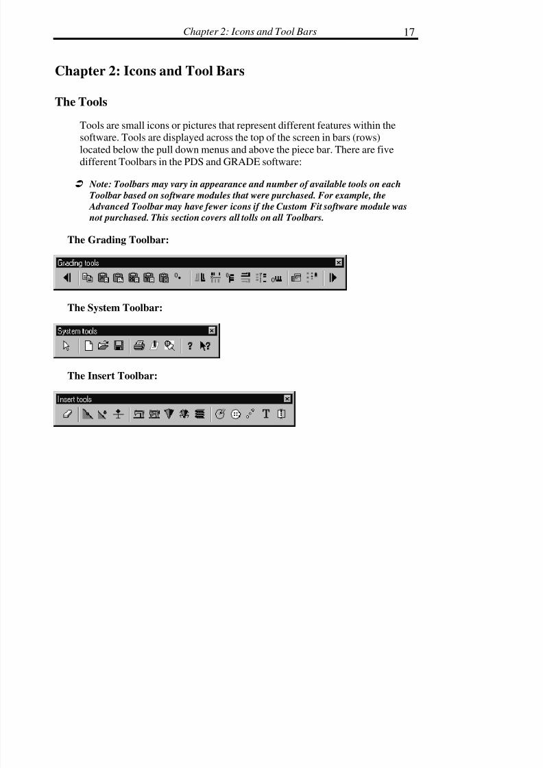
Tools are small icons or pictures that represent different features within the
software. Tools are displayed across the top of the screen in bars (rows)located below the pull down menus and above the piece bar. There are five
different Toolbars in the PDS and GRADE software:
! Note: Toolbars may vary in appearance and number of available tools on each
Toolbar based on software modules that were purchased. For example, the
Advanced Toolbar may have fewer icons if the Custom Fit software module was
not purchased. This section covers all tolls on all Toolbars.
The Grading Toolbar:
The System Toolbar:
The Insert Toolbar:

7/28/2019 OptiTex PDS User Manual
http://slidepdf.com/reader/full/optitex-pds-user-manual 42/727
Digitize, PDS & Grade Manual18
The Edit Toolbar:
The Modify Toolbar:
The General Toolbar:
The Advanced Toolbar:
The Custom Fit Toolbar:
The Accessories Toolbar:
7/28/2019 OptiTex PDS User Manual
http://slidepdf.com/reader/full/optitex-pds-user-manual 43/727
Chapter 2: Icons and Tool Bars 19
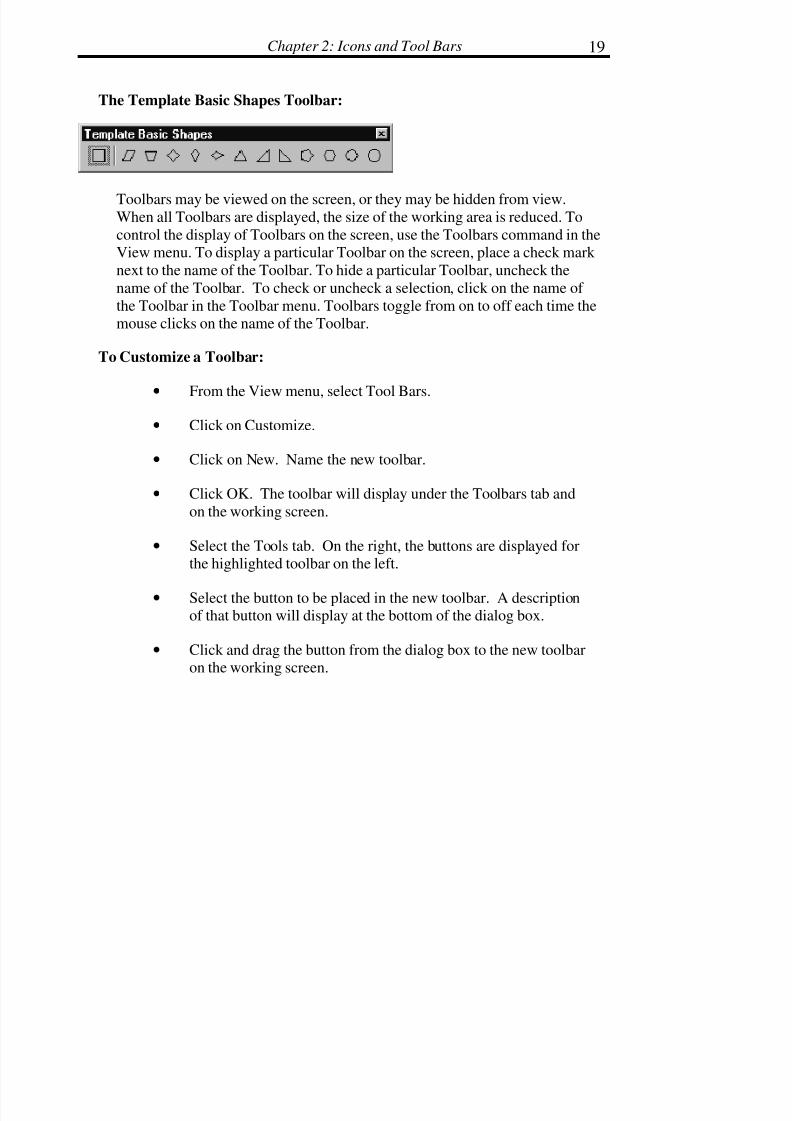
The Template Basic Shapes Toolbar:
Toolbars may be viewed on the screen, or they may be hidden from view.When all Toolbars are displayed, the size of the working area is reduced. To
control the display of Toolbars on the screen, use the Toolbars command in theView menu. To display a particular Toolbar on the screen, place a check mark
next to the name of the Toolbar. To hide a particular Toolbar, uncheck the
name of the Toolbar. To check or uncheck a selection, click on the name of
the Toolbar in the Toolbar menu. Toolbars toggle from on to off each time themouse clicks on the name of the Toolbar.
To Customize a Toolbar:
• From the View menu, select Tool Bars.
• Click on Customize.
• Click on New. Name the new toolbar.
• Click OK. The toolbar will display under the Toolbars tab and
on the working screen.
• Select the Tools tab. On the right, the buttons are displayed forthe highlighted toolbar on the left.
• Select the button to be placed in the new toolbar. A descriptionof that button will display at the bottom of the dialog box.
• Click and drag the button from the dialog box to the new toolbaron the working screen.
7/28/2019 OptiTex PDS User Manual
http://slidepdf.com/reader/full/optitex-pds-user-manual 44/727
Digitize, PDS & Grade Manual20
• Lift the mouse button to drop the button into the toolbar. Repeatthis until all desired buttons are placed in the toolbar.
• Click OK.
! !! ! Note: The buttons from the Template Basic Shapes toolbar cannot be transferred
to a customized toolbar.
To Reset a Toolbar:
Resetting a toolbar replaces any buttons that were taken out of a default
toolbar.
• From the View menu, select Tool Bars.
• Highlight the desired toolbar.
• Click Reset.
• Click Close.
! !! ! Note: The Reset command changes to the Delete command when a customized
toolbar or a Template toolbar is highlighted.
To Create a Template Toolbar:
A Template Toolbar is a toolbar in which the buttons are pattern pieces, whichcan be stretched to a desired length and width.
• Save your file as a Template (From the Template menu, select"Save As".)
• Exit PDS.

7/28/2019 OptiTex PDS User Manual
http://slidepdf.com/reader/full/optitex-pds-user-manual 45/727
Chapter 2: Icons and Tool Bars 21
• Open PDS.
• From the View menu, select Tool Bars. The Template will beadded to the bottom of the Toolbar list.
Engaging a Tool
Clicking once on the tool activates most tools. The cursor changes from the
normal pointer (an arrow) to another type of pointer that coincides with the
selected tool. For example, when the Walk tool is activated, the normalpointer turns into a cross hair line with two small feet. The two small feet
remind the user that the walk feature is currently activated.
Disengaging a Tool
Returning to the normal arrow pointer disengages a tool. To return to the
normal arrow pointer, either click on the tool that looks like an arrow, or click
the right mouse button, and select the first option in the pop up menu, “SelectTool” using the left mouse button.
Selecting another tool from one of the Toolbars also disengages tools currently
in use.
Grading Toolbar
The Grading Toolbar consists of tools that are directly related to the gradingcommands in the Grading pull down menu. These commands are also covered
in the Grading chapter.

7/28/2019 OptiTex PDS User Manual
http://slidepdf.com/reader/full/optitex-pds-user-manual 46/727
Digitize, PDS & Grade Manual22
Previous Point
Use Previous Point to select the next grading point in the counterclockwise
direction from the currently selected grading point. This tool eliminates using
the mouse to select grading points.
Copy Grading (Ctrl + G + C)
Use Copy Grading to place the X and Y grading increments of a selected
Grade point on the Windows clipboard. After clicking on the Copy Grading
tool, the X and Y grading increments are copied to the clipboard and remain
on the clipboard until another item is copied. Typically, the Copy Grading toolis used as the first step in pasting grading increments from one point to
another.
Paste Relative (Ctrl + G + R)
Paste Relative is used to automatically apply opposite grading on a piece when
using the Paste command related to the position of the point; left, right, up,down to the point where the grading value came from. Opposite grading refers
to grading increments that reverse in the negative or positive direction. Acheck mark next to Relative in the Grading menu indicates that the Relativeoption is activated. Another way to activate the Paste Relative option, is to
click on the Paste Relative icon in the Grading Toolbar. The Paste Relative
icon appears highlighted when activated.

7/28/2019 OptiTex PDS User Manual
http://slidepdf.com/reader/full/optitex-pds-user-manual 47/727
Chapter 2: Icons and Tool Bars 23
Paste Grading (Ctrl + G + P)
Use Paste Grading to paste the X and Y grading increments from the Windows
clipboard onto the selected point. Select the point where the same X and Ygrading increments are desired and then click the Paste Grading tool. After
clicking on the Paste Grading tool, the X and Y grading increments are pasted
on to the selected point. Typically, the Paste Grading tool is used as the second
step for pasting grading increments from one point on to another.
Paste X Grading (Ctrl + G + X)
Use Paste X grading to paste only the X grading increment that was copied
onto the clipboard. This command is used after the Copy Grading command.
Paste Y Grading (Ctrl + G + Y)
Use Paste Y grading to paste only the Y grading increment that was copiedonto the clipboard. This command is used after the Copy Grading command.
Paste Grading Around (Ctrl + G +A)
Use Paste Grading Around to paste the average of a specific grading valuearound a selected piece.
7/28/2019 OptiTex PDS User Manual
http://slidepdf.com/reader/full/optitex-pds-user-manual 48/727
Digitize, PDS & Grade Manual24
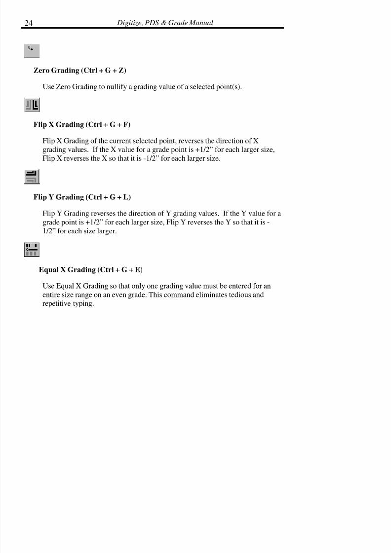
Zero Grading (Ctrl + G + Z)
Use Zero Grading to nullify a grading value of a selected point(s).
Flip X Grading (Ctrl + G + F)
Flip X Grading of the current selected point, reverses the direction of Xgrading values. If the X value for a grade point is +1/2” for each larger size,
Flip X reverses the X so that it is -1/2” for each larger size.
Flip Y Grading (Ctrl + G + L)
Flip Y Grading reverses the direction of Y grading values. If the Y value for a
grade point is +1/2” for each larger size, Flip Y reverses the Y so that it is -
1/2” for each size larger.
Equal X Grading (Ctrl + G + E)
Use Equal X Grading so that only one grading value must be entered for an
entire size range on an even grade. This command eliminates tedious andrepetitive typing.

7/28/2019 OptiTex PDS User Manual
http://slidepdf.com/reader/full/optitex-pds-user-manual 49/727
Chapter 2: Icons and Tool Bars 25
To Use Equal X Grading:
• Type in the X growth amount for the next larger size from thebase size.
• Move the cursor to the top of the X column in the grading table.
• Click the cursor with the left button one time to highlight theentire X column in black.
• Select Equal X Grading from the Grading menu or use the EqualX tool
• All sizes are now equally graded.
! !! ! Note: If the grading is not visible or only partially visible on the screen, press the
F4 key on the keyboard to activate all grading.
Equal Y Grading (Ctrl + G + Q)
Use Equal Y Grading so that only one value must be entered for an entire size
range on an even grade. This command eliminates tedious and repetitive
typing.
To Use Equal X Grading:
•Type in the Y growth amount for the next larger size from thebase size.
• Move the cursor to the top of the Y column in the grading table.
• Click the cursor with the left button one time to highlight the

7/28/2019 OptiTex PDS User Manual
http://slidepdf.com/reader/full/optitex-pds-user-manual 50/727

7/28/2019 OptiTex PDS User Manual
http://slidepdf.com/reader/full/optitex-pds-user-manual 51/727
Chapter 2: Icons and Tool Bars 27
Zero Y Grade (Ctrl + G + O)
Zero Y Grade quickly makes all grade values for all sizes, zero in the Y
column. This command is commonly used to remove grading from a particularpoint.
To Use Zero Y Grade:
• Select one or more grading points with the arrow tool. If selecting multiple points, drag the arrow in the clockwise
direction from the first point to the last point.
• Select Zero Y Grade from the Grading menu or use the Zero Y
icon.
• All sizes on the select point/s are now grading zero in the Ydirection.
Graded Nest
Allows building a graded nest using pieces that came from another CAD
application via a DXF, AAMA or any other file format where grading value
information and relationships between pieces is lost. For example, if a marker
is imported that contains a men’s shirt style including sizes S, M, and L, all thepieces are imported into SGS OptiTex software as separate pieces. No
relationships between sizes are imported with the data. The Graded Nest toolprovides the ability to stack all same pieces of different sizes into a graded nest
and relates the pieces as the same piece but different sizes.
7/28/2019 OptiTex PDS User Manual
http://slidepdf.com/reader/full/optitex-pds-user-manual 52/727
Digitize, PDS & Grade Manual28
To Use the Graded Nest Tool:
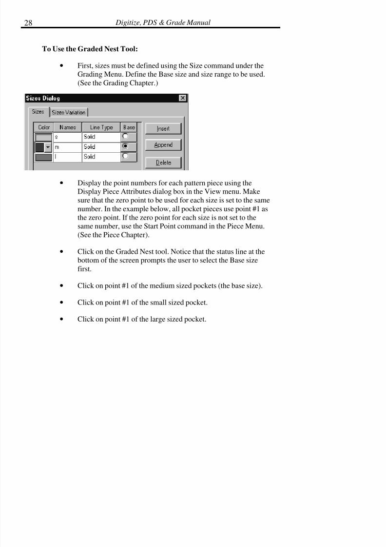
• First, sizes must be defined using the Size command under theGrading Menu. Define the Base size and size range to be used.
(See the Grading Chapter.)
• Display the point numbers for each pattern piece using the
Display Piece Attributes dialog box in the View menu. Makesure that the zero point to be used for each size is set to the same
number. In the example below, all pocket pieces use point #1 as
the zero point. If the zero point for each size is not set to thesame number, use the Start Point command in the Piece Menu.
(See the Piece Chapter).
• Click on the Graded Nest tool. Notice that the status line at thebottom of the screen prompts the user to select the Base size
first.
•Click on point #1 of the medium sized pockets (the base size).
• Click on point #1 of the small sized pocket.
• Click on point #1 of the large sized pocket.

7/28/2019 OptiTex PDS User Manual
http://slidepdf.com/reader/full/optitex-pds-user-manual 53/727
Chapter 2: Icons and Tool Bars 29
• The pocket pieces should now display as a graded nest. If thegraded nest is not visible, press the F4 key on the keyboard.
Grade Proportional
Grade Proportional is used to apply grading on curved pattern edges. Forexample, proportional grading is commonly used on the hemline of a circle
skirt or on scalloped edges.

7/28/2019 OptiTex PDS User Manual
http://slidepdf.com/reader/full/optitex-pds-user-manual 54/727

7/28/2019 OptiTex PDS User Manual
http://slidepdf.com/reader/full/optitex-pds-user-manual 55/727
Chapter 2: Icons and Tool Bars 31
System Toolbar
The System Toolbar consists of many standard Windows type tools as well asseveral SGS specific tools.
Pointer
The Pointer tool (sometimes called the Selection tool or the Arrow tool) is thedefault tool used in the PDS software. This tool is used to select pieces, points,
and line segments.
! !! ! Tip: Double click the Pointer tool to redraw the screen.
! !! ! Note: To access the Pointer tool without clicking on the Pointer icon, click the
right mouse button one time. With the left button, select the Pointer tool
from the pop-up menu.
New (Ctrl + N)
Use the new tool to start a new design (DSN) file. A DSN file contains all the
pieces necessary to make one complete garment or other sewn product. Whenthe New tool is selected, the Make Rectangle dialog box displays by default.
Enter specific length and width values for the new pattern piece or select
Cancel to bypass the Make Rectangle dialog box.The number of pieces in a DSN file is limited only by the amount of memoryavailable on your computer.

7/28/2019 OptiTex PDS User Manual
http://slidepdf.com/reader/full/optitex-pds-user-manual 56/727
7/28/2019 OptiTex PDS User Manual
http://slidepdf.com/reader/full/optitex-pds-user-manual 57/727

7/28/2019 OptiTex PDS User Manual
http://slidepdf.com/reader/full/optitex-pds-user-manual 58/727

7/28/2019 OptiTex PDS User Manual
http://slidepdf.com/reader/full/optitex-pds-user-manual 59/727

7/28/2019 OptiTex PDS User Manual
http://slidepdf.com/reader/full/optitex-pds-user-manual 60/727

7/28/2019 OptiTex PDS User Manual
http://slidepdf.com/reader/full/optitex-pds-user-manual 61/727

7/28/2019 OptiTex PDS User Manual
http://slidepdf.com/reader/full/optitex-pds-user-manual 62/727

7/28/2019 OptiTex PDS User Manual
http://slidepdf.com/reader/full/optitex-pds-user-manual 63/727

7/28/2019 OptiTex PDS User Manual
http://slidepdf.com/reader/full/optitex-pds-user-manual 64/727

7/28/2019 OptiTex PDS User Manual
http://slidepdf.com/reader/full/optitex-pds-user-manual 65/727
Chapter 2: Icons and Tool Bars 41
Angle
Angle indicates the angle of the notch from the line where the notch is placed.
To apply a notch on the outside of a pattern piece, use an angle setting of 180degrees. Other way to edit the notch angle, is using the mouse click. Click on
the "Angle by mouse click" and click again on the general direction of the
selected notch. It will be move to the click direction.
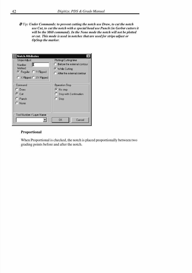
Attributes
The Attributes button activates the Notch Attributes dialog box. This dialog
box is used to establish parameters for an automatic cutter and to establishstripe adjust points when working with stripe, plaid, or repeated print fabrics.
Parameters for the cutter include notch type: draw, cut, or punch. Additionally,this area is used to establish operational stops (op stops) for temporarily
stopping an automatic cutter before or after cutting a piece.
7/28/2019 OptiTex PDS User Manual
http://slidepdf.com/reader/full/optitex-pds-user-manual 66/727

7/28/2019 OptiTex PDS User Manual
http://slidepdf.com/reader/full/optitex-pds-user-manual 67/727

7/28/2019 OptiTex PDS User Manual
http://slidepdf.com/reader/full/optitex-pds-user-manual 68/727
Digitize, PDS & Grade Manual44
7/28/2019 OptiTex PDS User Manual
http://slidepdf.com/reader/full/optitex-pds-user-manual 69/727

7/28/2019 OptiTex PDS User Manual
http://slidepdf.com/reader/full/optitex-pds-user-manual 70/727
Digitize, PDS & Grade Manual46
Distance from Grading Points
When this box is selected, all measurements originate from the previous or
next grading point only. If this box is not selected, all measurements originate
from the previous or next point regardless of whether it is a grading point or anon-grading point.
7/28/2019 OptiTex PDS User Manual
http://slidepdf.com/reader/full/optitex-pds-user-manual 71/727
Chapter 2: Icons and Tool Bars 47
! !! ! Note: While this dialog box remains open, different notches may be selected and
changed. After each notch is changed, click the Apply button. No changes
are implemented unless the Apply button is clicked. After editions are final,
click Close to exit.
! !! ! Tip: To create a notch that is the same distance from a point for all sizes
(sometimes referred to as a notch with a tangent rule), use either the From Previous, or from Next options. Use APPLY to apply changes, then use
COPY TO ALL to copy the notch to all sizes, then use REGRADE ALL, so
that the notch behaves the same on all sizes.
Seam
Use the Seam tool to add seam allowance to piece.
! !! !
Note: Refer to the Seam section in the Piece chapter for more information.
To Add Seam Allowance:
• Select the Seam Allowance tool.
• Either select a point on a piece indicating that seam allowance isto be added to the entire piece, or select the segment on thepiece on which to apply seam allowance.
• To select a single point for adding a constant seam allowance tothe entire piece, point the Seam Allowance tool at a point on the
piece and click the mouse twice.
• To select a segment or multiple segments, point the SeamAllowance tool at the first point and click the mouse, then drag
the Seam Allowance tool to the last point of the segment andclick the mouse.

7/28/2019 OptiTex PDS User Manual
http://slidepdf.com/reader/full/optitex-pds-user-manual 72/727
Digitize, PDS & Grade Manual48
! !! ! Note: It is not recommended to choose a curve point as a start or end point for a
seam.
• When the Point Attributes dialog box displays, enter the amountof the allowance in the Seam Width box at the lower left of thedialog box. If the seam allowance is added to the entire piece,
select the appropriate corner type by clicking on the
corresponding corner icon. If the seam allowance is added to asegment of the piece, choose the type of corner to apply to the
start of the seam and to the end of the seam from the Start Seam/
End Seam boxes. The icons illustrate available corner types. To
leave the corner types as standard corners, it is not necessary tomake a corner selection.
• Click OK after appropriate information is added.
7/28/2019 OptiTex PDS User Manual
http://slidepdf.com/reader/full/optitex-pds-user-manual 73/727

7/28/2019 OptiTex PDS User Manual
http://slidepdf.com/reader/full/optitex-pds-user-manual 74/727

7/28/2019 OptiTex PDS User Manual
http://slidepdf.com/reader/full/optitex-pds-user-manual 75/727
Chapter 2: Icons and Tool Bars 51
• Click the left mouse button on the first point of the dart (See thediagram below).
! !! ! Note: There must be existing points on the first and last dart points on the piece’s
boundary. If points do not exist where the dart is to be placed, use the Add
Relative command in the Edit menu. (See the Edit chapter).
• Click the left mouse button again on the last point of the dart.The cursor automatically becomes the center point (apex) of theline created between the two selected points.
• Drag the cursor internally to create the dart depth and click the
mouse button a third time. After clicking the mouse button a
third time the Dart Attributes dialog box will appear.
! !! ! Note: The dart is always created symmetrically.
•When the Dart Attributes dialog box displays, select the desiredoptions.
• Click OK.

7/28/2019 OptiTex PDS User Manual
http://slidepdf.com/reader/full/optitex-pds-user-manual 76/727
Digitize, PDS & Grade Manual52
Dart Attributes Dialog Box:
Name
Use name field to give a name for the dart apex point.
! !! ! Note: If your dart apex point as a name, you will be able to apply a grading rule
(by using “Apply Rule by name” command from grading menu) for the
dart apex without selecting the dart apex point.

7/28/2019 OptiTex PDS User Manual
http://slidepdf.com/reader/full/optitex-pds-user-manual 77/727
Chapter 2: Icons and Tool Bars 53
Direction
Select the direction to fold the dart, clockwise, or counter clockwise. The
Overlap box below must be checked in order to select a direction.
Overlap
Check the Overlap box to establish that the dart is to be folded in a specific
direction. Checking this box activates the Direction options above.
Depth
Use the Depth field to view the current depth of the dart or enter a specificdepth for the dart.
7/28/2019 OptiTex PDS User Manual
http://slidepdf.com/reader/full/optitex-pds-user-manual 78/727
Digitize, PDS & Grade Manual54
Equal for All Sizes
If the dart should not grade with the pattern piece, check this box. If the dart
should grade with each size, uncheck this box.
Drill, Draw, Cut, None
Select the desired option for the drill hole.
Distance
Enter the distance to place the drill from the apex of the dart. To place the drill
hole one half inch below the apex, enter .5 in the Distance box.
To Pivot a Dart to a New Location:
• Select the Dart tool.
• Click and hold the left mouse button on the center point of thedart.
• Drag the cursor to the new location along the perimeter of thepattern piece where the dart is to be pivoted Click the mouse a
second time.
• As shown in the diagram, click on point #1 and drag to #3. Click the mouse button again at point #3 to pivot the entire dart to the
side seam. This step directly relates manual pattern making
when closing a dart after the pattern has been slashed.

7/28/2019 OptiTex PDS User Manual
http://slidepdf.com/reader/full/optitex-pds-user-manual 79/727
Chapter 2: Icons and Tool Bars 55

7/28/2019 OptiTex PDS User Manual
http://slidepdf.com/reader/full/optitex-pds-user-manual 80/727

7/28/2019 OptiTex PDS User Manual
http://slidepdf.com/reader/full/optitex-pds-user-manual 81/727

7/28/2019 OptiTex PDS User Manual
http://slidepdf.com/reader/full/optitex-pds-user-manual 82/727

7/28/2019 OptiTex PDS User Manual
http://slidepdf.com/reader/full/optitex-pds-user-manual 83/727
Chapter 2: Icons and Tool Bars 59
Pleat
The Pleat tool is used to create pleats. Both Box pleats and Knife pleats may
be added using the Pleat tool. The Pleat tool allows for even and variable(uneven) pleating. Pleat depth and the amount of spacing between each pleat
may also be specified in the Pleat dialog box.
! !! ! Note: Error messages appear if a pleat is placed over a sharp curve or
corner. Error messages also appear if the number, depth, and distance between each pleat exceed the existing piece’s dimensions.
Error messages indicate that the values entered into the Pleat dialog
box are incorrect.
To Make a Pleat:
• Select the Pleat tool.
• Click the mouse on the piece at the point where the pleat is to
start.
• When the Move Point dialog box displays, either confirm thevalues in the Move Point dialog box by pressing Enter, or enter
the desired values and click OK.
• Click the mouse on the piece at the point where the pleat is toend. Repeat step 3.
• When the Define Pleat Characteristics dialog box displays, enterthe desired pleat information. (See the Pleat CharacteristicsDialog Box section below).
• Click OK.

7/28/2019 OptiTex PDS User Manual
http://slidepdf.com/reader/full/optitex-pds-user-manual 84/727
Digitize, PDS & Grade Manual60
Pleat Characteristics Dialog Box:
Box
Select Box Pleat in order to create box pleats. This type of pleat has four
folds. When Box Pleat is checked, an image of the pleat displays on the upper
right side of the dialog box.
Knife
Select Knife Pleat in order to create knife pleats. This type of pleat has two
folds. When Knife Pleat is checked, an image of the pleat displays on theupper right side of the dialog box.

7/28/2019 OptiTex PDS User Manual
http://slidepdf.com/reader/full/optitex-pds-user-manual 85/727
Chapter 2: Icons and Tool Bars 61
CCW Folded
This option is activated only when the Knife Pleat box is selected. Selecting
this option makes the knife pleats fold in the counter clockwise direction. If this option is not selected, the pleats fold in the clockwise direction.
Variable Pleat
The variable pleat option is used to create uneven pleats. For example, avariable pleat may be 1” at the top of the pleat and .5” at the bottom of the
pleat. If this option is not selected, the pleat is even or parallel from top to
bottom. See the diagram below for illustration.
Depth
Depth refers to the size (thickness) of the pleat. For example, a pleat may be
1” in depth.
First
First is activated only when the Variable option is selected. The depth of thepleat on the first line is entered in this box, and the depth of the pleat on the
second line is entered in the above box. The above box, “Depth,” changes to
“Second” when the variable option is activated. This prompts the user to entera pleat depth for the second line.
Number of Pleats
Enter the number of pleats in this box.
Pleats Distance
This option is only activated when 2 or more pleats are entered in the Number
of Pleats box above. Enter the distance between pleats. For example, theremay be two pleats on a pattern piece that are spaced 2” apart.
7/28/2019 OptiTex PDS User Manual
http://slidepdf.com/reader/full/optitex-pds-user-manual 86/727
Digitize, PDS & Grade Manual62
Pleats First Distance
This option is only activated when 2 or more pleats are entered in the Number
of Pleats box and when the Variable option is selected. Enter the distancebetween pleats on the first pleat line in this box. In this case, the distance
between pleats on the second pleat line is entered in the Pleats Distance box
above.
Counter Clockwise
This option controls the direction that the pleats are placed from the originaldefined pleat line (see step #2 in the “To Make A Pleat” section). If this box is
checked, pleats are placed in the counterclockwise direction from the original
line. If the box is unchecked, pleats are placed in the clockwise direction fromthe original line.

7/28/2019 OptiTex PDS User Manual
http://slidepdf.com/reader/full/optitex-pds-user-manual 87/727
Chapter 2: Icons and Tool Bars 63
! !! ! Note: See the following diagram for the results of the above options on a
skirt pattern.

7/28/2019 OptiTex PDS User Manual
http://slidepdf.com/reader/full/optitex-pds-user-manual 88/727
Digitize, PDS & Grade Manual64
Circle
Use the Circle tool to create a circular line on a piece. Circles may be created
with a specific radius, and they may also be duplicated.
To Make a Circular Line:
• Select the Circle tool.
• Click the mouse on the piece where the center of the circle is tobe placed.
• Drag the mouse away from the center point to the approximatesize of the desired circular line, and click the mouse again.

7/28/2019 OptiTex PDS User Manual
http://slidepdf.com/reader/full/optitex-pds-user-manual 89/727
Chapter 2: Icons and Tool Bars 65
• When the Edit Circle dialog box displays, confirm the existingradius by pressing Enter, or specify an exact radius by entering aspecific value in the Radius box.
! !! ! Note: Use the Name filed to give a new to your circle
! !! ! Note: If your circle as a name you will be able to apply a grading rule (by
using “Apply Rule by name” command from grading menu) for the
dart button without selecting the dart apex point.
• OPTIONAL: To create duplicate circles, press the Duplicatebutton and enter the necessary information in the Duplicate
dialog box.
• Press OK.

7/28/2019 OptiTex PDS User Manual
http://slidepdf.com/reader/full/optitex-pds-user-manual 90/727
Digitize, PDS & Grade Manual66
Button
Use the Button tool to create drill holes. Buttons are also used to mark a match
point, for stripe matching on a marker when working with stripe, plaid, orrepeated print fabrics. Buttons may be duplicated quickly and easily without
having to recreate each button. The button tool can also be used to mark a drill
hole for pockets or as OpStop for the cutting machine.
Buttons can be graded or they can serve as stack points. (Refer to the Stack
Point command in the Grading chapter.)
To Create a Button (drill hole):
• Select the Button tool.
• Click the mouse on the piece where the button is to be placed. If the mouse is clicked on an existing point, the Add Point Relative
dialog box displays which allows the user to specify a specificdistance from the existing point where the button is to be placed.
If the mouse is not clicked on an existing point, the Button
Attributes dialog box displays.
7/28/2019 OptiTex PDS User Manual
http://slidepdf.com/reader/full/optitex-pds-user-manual 91/727
Chapter 2: Icons and Tool Bars 67
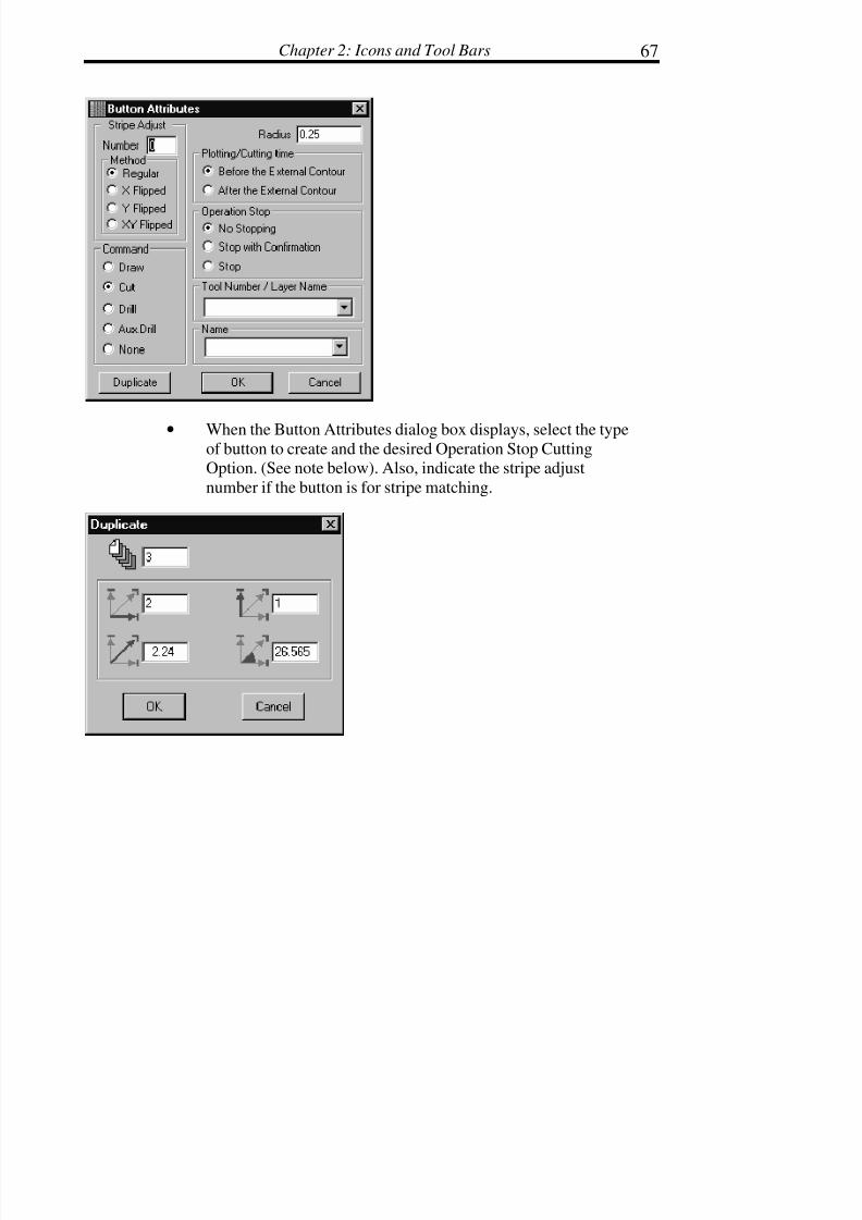
• When the Button Attributes dialog box displays, select the typeof button to create and the desired Operation Stop CuttingOption. (See note below). Also, indicate the stripe adjust
number if the button is for stripe matching.

7/28/2019 OptiTex PDS User Manual
http://slidepdf.com/reader/full/optitex-pds-user-manual 92/727
Digitize, PDS & Grade Manual68
• OPTIONAL: To create duplicate buttons, press theDUPLICATE button and enter the necessary information in theDuplicate dialog box.
• Click OK.
! !! ! Note: Op Stop options control whether the cutter stops before, after, or does
not stop before or after a drill.
! !! ! Note: Buttons are also created using the Add Relative command from the
Edit pull down menu. This method of adding buttons allows placement of the buttons a specific distance from an existing point.
(Refer to the Edit chapter for details).
Buttons on Distance
Use Buttons on Distance to add several buttons on equal distance.
• Select the Button on Distance tool.
• Place the Button on Distance tool directly over a point, if the
buttons are to be
related to that point, where the buttons will begin. If not, placethe Button on
Distance tool to the desired location on the piece. Click with the
mouse button.
• Drag the tool to the point where the buttons will end. Click withthe mouse button.
• The Set Buttons on equal distance dialog box will display.

7/28/2019 OptiTex PDS User Manual
http://slidepdf.com/reader/full/optitex-pds-user-manual 93/727
Chapter 2: Icons and Tool Bars 69
• Enter the Number of buttons desired
• Between - the number of buttons in between the first and lastbutton
• Before - the number of buttons before the first button
• After - the number of buttons after the last button
• Distance shows the distance between the first & last button.
• Enable the Set First option in order to display the first button.
• Enable the Set Last option in order to display the last button.

7/28/2019 OptiTex PDS User Manual
http://slidepdf.com/reader/full/optitex-pds-user-manual 94/727
Digitize, PDS & Grade Manual70
• Enter a value for the Radius of the buttons.
• Select the Command for either a plotter or cutter.
• Click OK.
Text
Use the Text tool to add text. This tool is commonly used to add instructions
or other information to a piece to aid the cutting process. The text is plotted on
the pieces either from the PDS software, or it is plotted from the Markingsoftware. Text may be added at an angle.
! !! ! Note: It is not necessary to use the text tool for standard piece information
such as the piece name, style name, piece code, piece description, size name, or sequence number. Standard piece information in entered
using the Piece Information dialog box. (See the Piece Chapter for details). This information is controlled in the Marking software. It is
optional to plot all, some, or none of this “standard” information. See the SGS Marking Manual for more details.
To Place Text:
• Click the Text tool. The arrow becomes a text cursor.
• Move the cursor to the desired position within the selected
pattern piece and click the mouse button.
• When the Enter Text at Screen Position dialog box displays,type the appropriate text in the dialog box.
• Click OK. The text displays on the screen.

7/28/2019 OptiTex PDS User Manual
http://slidepdf.com/reader/full/optitex-pds-user-manual 95/727
Chapter 2: Icons and Tool Bars 71
To Change or Delete Text:
• Select the Text tool.
• Select the text to be changed or deleted by clicking on top of the
text.
• When the Enter Text at Screen Position dialog box displays,either change the existing text or use the delete key or the
backspace key to remove unwanted text.
• Click OK.
! !! ! Note: There are limitations to the text size according to your output device.
The text size and font are changed through the Fonts command in
the Options menu.
Pleat Lines
The Pleat Lines command has three sub options: Add, Add by Angle &
Remove. Pleat lines are a special line type that runs between 2 points. It is a
dashed line that is attached to its end points. If you move on of these points,
the Pleat line will move with it.
To define an Pleat line between two points:
• Using the Pleat Lines tool, select the two points by clicking onthe first point, and then hold down the Shift key while selectingthe second point.
Or

7/28/2019 OptiTex PDS User Manual
http://slidepdf.com/reader/full/optitex-pds-user-manual 96/727
Digitize, PDS & Grade Manual72
• Using the Pleat Lines tool, click on a point and then drag thecursor to the next point and click again with left mouse button.To remove the Pleat line either select the two points and choose
the ‘Remove’ option from the Pleat command, or select the Pleat
line with the pointer (arrow) and use the ‘Delete’ (Del) key from
the keyboard. Remember that any selected element becomesRED while the cursor is close to that element.

7/28/2019 OptiTex PDS User Manual
http://slidepdf.com/reader/full/optitex-pds-user-manual 97/727
Chapter 2: Icons and Tool Bars 73
The Edit Toolbar
Tools in this Toolbar are used to reposition pieces on the screen such as flip
and rotate pieces. It also allows you to edit the contour of the piece by usingthe move point tools.
Move Point
Select the Move Point Tool to move a single point.
To Move a Single Point:
• Select the Move Point tool.
• Click on the point to be moved. The selected point is nowattached to the cursor.
• Move the point to the desired position and click the mouse againto anchor the point. The Move Point dialog box displays with
the new point coordinates.

7/28/2019 OptiTex PDS User Manual
http://slidepdf.com/reader/full/optitex-pds-user-manual 98/727
Digitize, PDS & Grade Manual74
• OPTIONAL: Enter the desired values to move the point to a
specific location.
• Click OK.
! !! ! Note: The display of the Move dialog box may be turned off by clicking the Disable This Dialog option. The dialog box is not displayed until this
option is reversed using the Open Move Dialog Box command in the
Options menu.

7/28/2019 OptiTex PDS User Manual
http://slidepdf.com/reader/full/optitex-pds-user-manual 99/727
Chapter 2: Icons and Tool Bars 75
Move Proportional
Select the Move Proportional tool to move a section proportionally between
two grading points.
To Move Points Proportionally Between Two Grading Points:
• Select the Move Proportional tool.
• Click on the grading points on each end of the segment to bemoved proportionally.
• Move the points to the desired position and click the mouse
again to anchor the points. The Move Segment Proportional
dialog box displays.
• OPTIONAL: Enter the desired values to move the points to aspecific location.
• Click OK.
! !! ! Note: Segments may be moved proportionally between non-grading points,
however, the results are different. Grading point’s function as
anchoring points for the segment that is being proportionally moved.
! !! ! Note: The display of the Move dialog box may be turned off by clicking the
Disable This Dialog option. The dialog box is not displayed until this option is reversed using the Open Move Dialog Box command in the
Options menu.

7/28/2019 OptiTex PDS User Manual
http://slidepdf.com/reader/full/optitex-pds-user-manual 100/727
Digitize, PDS & Grade Manual76
Move Parallel
The Move Parallel tool moves a segment of a piece. For example, this tool is
commonly used to extend or lengthen one side of a pattern piece.
To Move Parallel:
• Select the Move Parallel tool.
• Click and drag the cursor in a clockwise direction to select thepoints to move.
! !! ! Tip: After selecting points, the Move Point command from the Edit menu
may also be used to move the selected group of points.
• Click on any of the selected points and move the segment to thedesired location.
• Click the left mouse button to anchor the position. The MoveParallel dialog box displays.

7/28/2019 OptiTex PDS User Manual
http://slidepdf.com/reader/full/optitex-pds-user-manual 101/727
Chapter 2: Icons and Tool Bars 77
• OPTIONAL: Enter values for the exact placement of thesegment in the X and Y directions.
• Click OK.
! !! ! Note: The display of the Move Parallel dialog box may be turned off by
clicking the Disable This Dialog option. The dialog box is not displayed until this option is reversed using the Open Move Dialog
Box command in the Options menu.
Round Corner
Round Corner is used to create a curved intersection where two lines intersecton a boundary line as well on a multiple point selection.
To Create a Rounded Corner:
• Select the intersection point(s) to create a rounded corner.
• Select ROUND CORNER from the EDIT menu.
• Enter a value for the radius of the rounded corner in the dialogbox.
! !! ! Note: Round corner command supports multiply corners point selection.
! !! ! Tip: To undo the rounded corner, select Undo from the Edit menu.

7/28/2019 OptiTex PDS User Manual
http://slidepdf.com/reader/full/optitex-pds-user-manual 102/727
Digitize, PDS & Grade Manual78
Align Points
The Align Points command aligns a selected group of points horizontally,
vertically or by a specified angle.
When choosing the Align Points command, more than one point must be
selected. To select points, click and drag the cursor clockwise along the piececontour until the appropriate points are selected (always select points in a
clockwise direction).
To Align Points
• Click and drag to select the points to be aligned.
• From the EDIT menu choose ALIGN POINTS.
• When the Align Points dialog box displays, select the alignmentmode: Horizontal, Vertical, or enter a value in the Angle box toalign points on an angle.
• Click OK.
Set Point (0,0)
Select the Set (0,0) Point command to change the start measuring point for theselected pattern piece in the working area. This command is used in
conjunction with the Coordinates command in the Display menu. Thiscommand is particularly useful during the freehand editing of points with the
mouse because it shows the relative moving position of the cursor in any
direction.

7/28/2019 OptiTex PDS User Manual
http://slidepdf.com/reader/full/optitex-pds-user-manual 103/727
Chapter 2: Icons and Tool Bars 79
! !! ! Tip: Use this command to add notches, add or move points, etc. with the mouse by opening the Coordinates window in the Display menu.
To set (0,0) Point:
• Select the point to use as the new start point.
• From the PIECE menu choose SET (0,0) POINT.
! !! ! Note: Changing the 0,0 point causes the grid to align itself to the 0,0 point.
(To view the grid, check the Grid and Stripes option in the Options pull down menu.)
Start Point
Select this command to define which grading point will become the first point.
The first grading point and the order of all other grading points is especially
important when using All Point (Global) Grading rules. To display pointnumbers, select Point Numbers from the Display pull down menu.
! !! ! Note: While using the All Point Grading (Global) rules, point numbers play
an important role.
To Set the Start Point:
• Select the point to set as the first piece point.
• From the GRADING menu choose START POINT.
• The selected point is now the first point. Number one GlobalGrading rules will apply to this point.
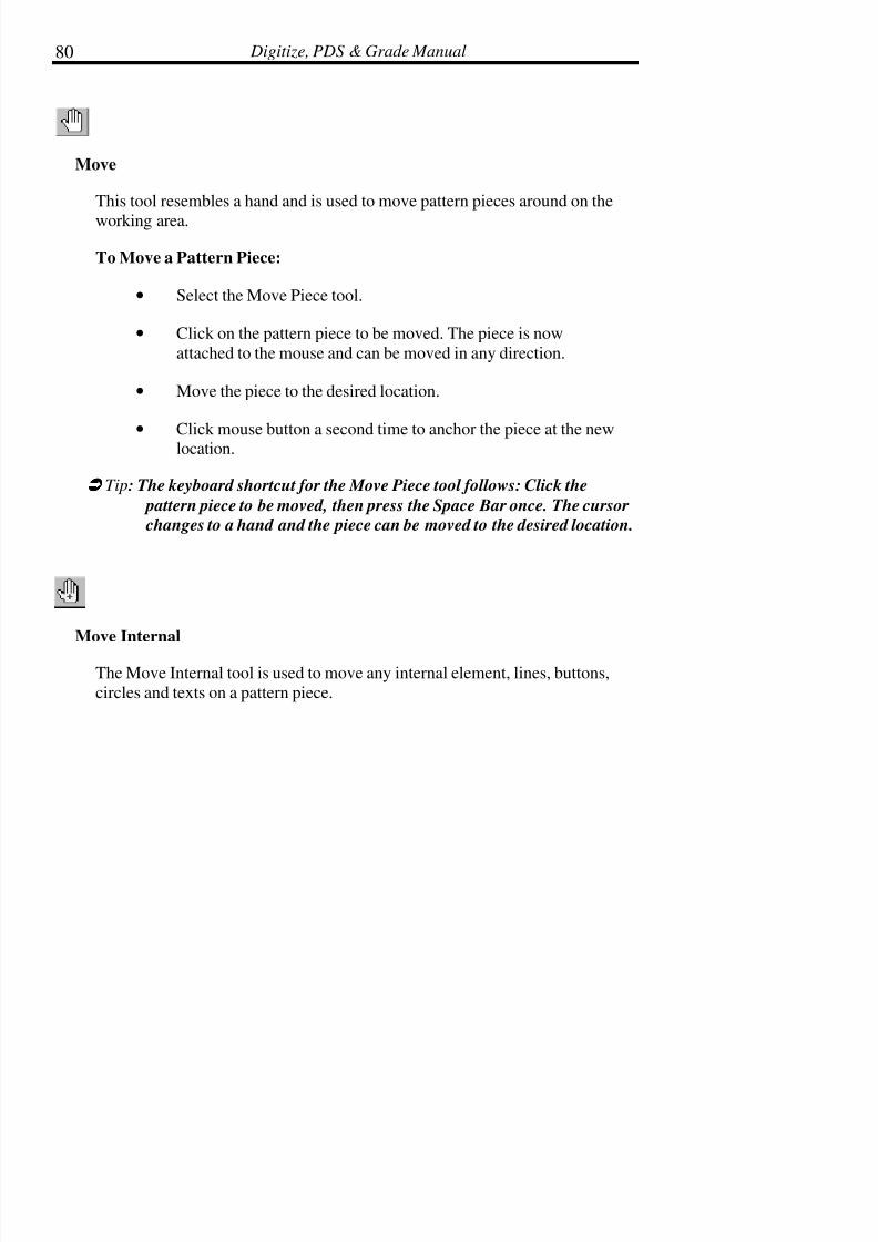
7/28/2019 OptiTex PDS User Manual
http://slidepdf.com/reader/full/optitex-pds-user-manual 104/727
Digitize, PDS & Grade Manual80
Move
This tool resembles a hand and is used to move pattern pieces around on the
working area.
To Move a Pattern Piece:
• Select the Move Piece tool.
• Click on the pattern piece to be moved. The piece is now
attached to the mouse and can be moved in any direction.
• Move the piece to the desired location.
•
Click mouse button a second time to anchor the piece at the newlocation.
! !! ! Tip: The keyboard shortcut for the Move Piece tool follows: Click the
pattern piece to be moved, then press the Space Bar once. The cursor changes to a hand and the piece can be moved to the desired location.
Move Internal
The Move Internal tool is used to move any internal element, lines, buttons,
circles and texts on a pattern piece.
7/28/2019 OptiTex PDS User Manual
http://slidepdf.com/reader/full/optitex-pds-user-manual 105/727
Chapter 2: Icons and Tool Bars 81
To Move an Internal Element on a Pattern Piece:
• Select the Move Internal command.
• Click on the internal element to be moved. The internal elementis now attached to the mouse and can be moved in any direction.
• Move the internal element to the desired location.
• Click mouse button a second time to anchor the piece at the newlocation.
! !! ! Note: You can also copy internal elements to any location on the pattern by
using the Shift + move Internal tool.
Select Rectangle
Selects several internal elements at once (including the baseline).
• Select the piece with the internals to be highlighted.
• Select the Select Rectangle tool.
• Click with the mouse button and drag the cursor so that arectangle is defined around the desired internals.
• Lift the mouse button up to reveal which internals arehighlighted.
• The Copy / Paste Internals (Edit Menu) function can now beperformed.

7/28/2019 OptiTex PDS User Manual
http://slidepdf.com/reader/full/optitex-pds-user-manual 106/727
Digitize, PDS & Grade Manual82
Rotate Segment
Select the Rotate Segment tool to alter a section by rotating it around a pivot
point. The pivot point can be placed anywhere on the piece. You can use therotate segment for slash and spread purposes.
To Rotate a Segment:
• Select the Rotate Segment tool.
• Click the mouse at the location to place the pivot point. A smallred X displays to mark the spot.
• Click and drag the cursor in a clockwise direction to select the
segment to Rotate.
• Click on one of the selected points and drag in the desireddirection. The segment rotates around the pivot point as
it is dragged.
• Click the left mouse button to anchor the rotated segment.
The Rotate Angle dialog box displays.

7/28/2019 OptiTex PDS User Manual
http://slidepdf.com/reader/full/optitex-pds-user-manual 107/727
Chapter 2: Icons and Tool Bars 83
• OPTIONAL: Enter new values to define specific measurements.
• Click OK.
! !! ! Tip: To change the cursor back to the normal pointer (arrow), click the
right mouse button and select Previous from the pop up menu.
Rotate Piece
Use the Rotate Piece command to rotate the entire piece around a pivot point.
To Rotate a Piece:
• Either select a point with the pointer, and then select theROTATE PIECE tool to establish a specific pivot point. Or,
simply select the ROTATE PIECE tool to rotate from the centerof the piece.
• The piece is now controlled by the cursor. Move the cursor tothe location where the piece is rotated as desired. Click themouse button.
• When the Rotate Internal Angel dialog box displays, click OK toaccept the rotation angle, or enter specific angle values for the
rotation.
! !! ! Note: Pieces are also rotated by selecting the Rotate option from the Piece menu. (Refer to the Rotate command in the Piece Menu).

7/28/2019 OptiTex PDS User Manual
http://slidepdf.com/reader/full/optitex-pds-user-manual 108/727
Digitize, PDS & Grade Manual84
Flip Horizontal
This command flips the current pattern piece 180ø along the Y-axis (Back and
Forth).
Flip Vertical
This command flips the current pattern 180ø along the X-axis (Up and Down).

7/28/2019 OptiTex PDS User Manual
http://slidepdf.com/reader/full/optitex-pds-user-manual 109/727
Chapter 2: Icons and Tool Bars 85
The Modify Toolbar
This toolbar is used to modify the piece or elements of the piece according to
the base line.
Rotate
Select the Rotate command to rotate a piece, internal element or baseline by a
specified number of degrees to the left or right.
To Rotate a Pattern Piece:
• Select the piece to rotate.
• From the PIECE menu choose ROTATE.
• When the Rotate Piece or Inner Element dialog box displays,check the Piece box.

7/28/2019 OptiTex PDS User Manual
http://slidepdf.com/reader/full/optitex-pds-user-manual 110/727
Digitize, PDS & Grade Manual86
• Enter the desired rotation value.
• Select the rotation direction, left or right.
! !! ! Note: The selected piece rotates each time the Left or Right button is
selected. The piece and the base line rotate as if they are locked
together.
To Rotate a Selected Element:
• Select an internal element (internal line, text, circle, etc.).
• From the PIECE menu choose ROTATE.
• When the Rotate Piece or Inner Element dialog box is displayed,
check the Selected Element box.
• Enter the desired rotation angle.
• Select the rotation direction, left or right.
! !! ! Note: The selected element rotates each time the Left button or Right
button is selected.
To Rotate Piece Over Base:
• Select the baseline or the piece.
• From the PIECE menu choose ROTATE.
• When the Rotate Piece or Inner Element dialog box is displayed,check the Baseline box.
• Enter the desired rotation value.
• Select the rotation direction, left or right.

7/28/2019 OptiTex PDS User Manual
http://slidepdf.com/reader/full/optitex-pds-user-manual 111/727
Chapter 2: Icons and Tool Bars 87
! !! ! Note: The outcome of Rotate when using the Baseline Only option is the
same regardless of whether the baseline or the entire piece is selected.
! !! ! Note: The piece rotates and the baseline remains in its original position
each time the Left or Right button is selected.
Rotate to Baseline
The Rotate to Initial Base line command is used to rotate the piece back to its
original positioning. The base line, or grain line, is a line (usually horizontal)which ensures the placement of the piece is in the correct direction on the
screen and on the marker.
To Rotate to Initial Base line:
• Make sure everything is ungrouped.
• From the PIECE menu choose ROTATE TO INITIAL BASELINE.
• The pattern piece is returned to its original position, and allinternal elements are rotated along with the piece. This
command also sets the current base line to a horizontal position.
The ratio between the base line and the contour remainsconstant.
Rotate Line Parallel to Segment
Use Base Parallel to Segment to realign the base line to another internal line or
to a line segment on the piece’s boundary.

7/28/2019 OptiTex PDS User Manual
http://slidepdf.com/reader/full/optitex-pds-user-manual 112/727
Digitize, PDS & Grade Manual88
To Make the Base Line Parallel to a Segment:
• Select the 2 point internal line or line segment to which the baseline will be aligned.
• From the PIECE menu, select BASE PARALLEL TOSEGMENT.
• The base line realigns with the selected segment.
! !! ! Note: When using a line segment from the piece’s boundary, the direction
and sequence of choosing the two points is important affects the direction of the base line. If the base line is placed outside the piece
after using this command, use the Make New Base line command to
move it inside the piece (See the following section).
New Base Line
This command is used to edit base lines that run off a piece. Sometimes base
lines move to the outside of the piece while working with the Cut tool or using
the Create Parallel to Segment command.
This command is useful if the base line was not digitized, or if two pieces were joined resulting in an odd shaped piece. This command places the current base
line inside the piece close to the center.
! !! ! Note: The length of the base line may change during this process.To Make a New Base line:
• From the PIECE menu choose MAKE NEW BASE LINE.
• The Base line is placed closer to the center of the pattern piece.
7/28/2019 OptiTex PDS User Manual
http://slidepdf.com/reader/full/optitex-pds-user-manual 113/727
Chapter 2: Icons and Tool Bars 89
Mirror
This command creates a new piece exactly the same as the selected piece
except the new piece has two symmetrical halves made from the originalpiece. Note that this command creates an exact symmetric duplicate, which is
the same on both sides.
To Mirror a Pattern Piece:
• Select two consecutive points by clicking on the first point, thendragging (clockwise) to the next point.
• From the PIECE menu choose MIRROR.
•
A new piece is created which is symmetrically placed accordingto the selected points. The new piece displays in the furthermost
right-hand box in the Piece Display Bar. See the diagram below.
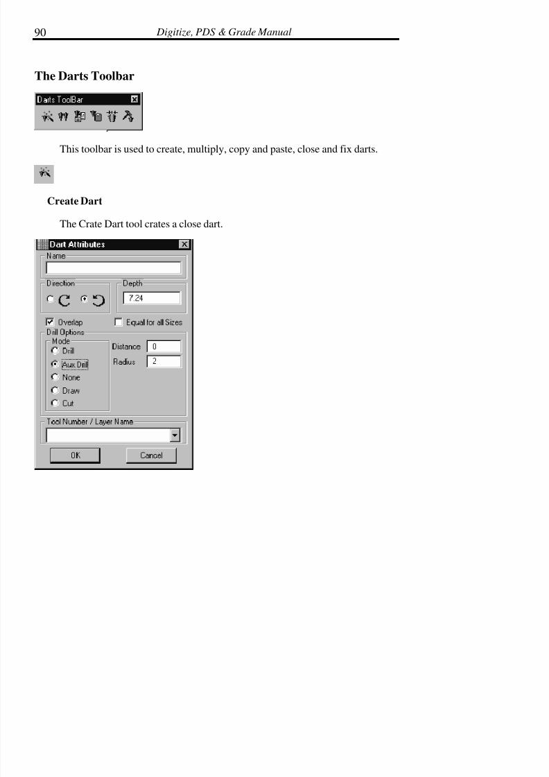
7/28/2019 OptiTex PDS User Manual
http://slidepdf.com/reader/full/optitex-pds-user-manual 114/727
Digitize, PDS & Grade Manual90
The Darts Toolbar
This toolbar is used to create, multiply, copy and paste, close and fix darts.
Create Dart
The Crate Dart tool crates a close dart.
7/28/2019 OptiTex PDS User Manual
http://slidepdf.com/reader/full/optitex-pds-user-manual 115/727
Chapter 2: Icons and Tool Bars 91
• From the DART menu chose CREATE DART.
• The Dart Attributes Dialog Box Appears.
• When the Dart Attributes dialog box displays, select the desiredoptions.
• Click OK.
Multiply Dart
The Multiply Darts command creates several darts on a selected segment at the
same time.
To create a multidart:
• Click and drag to the points on a segment where the darts are tobe created.
• From the Darts menu select Open Multiple Darts.
• The Open MultiDart dialog box will display.
• Enter the desired multiple dart information and click OK.
• The darts will be created on the first and last selected points. If more than 2 darts are created, they will be equally distributed
between the points.

7/28/2019 OptiTex PDS User Manual
http://slidepdf.com/reader/full/optitex-pds-user-manual 116/727
Digitize, PDS & Grade Manual92
The below dialog will be displayed so you can make any specifications that
will apply to all new darts.
Copy Dart
Use the Copy Dart command to copy selected Dart to the clipboard. Then use
the Paste Dart command to paste the copied Dart into the same DSN file or todifferent DSN file. The copied selection can continue to be pasted until
something else is placed onto the clipboard.
• Select the Dart to be copied.
• From the DART menu choose COPY DART.
• Open the layout where the object is to be pasted.

7/28/2019 OptiTex PDS User Manual
http://slidepdf.com/reader/full/optitex-pds-user-manual 117/727
Chapter 2: Icons and Tool Bars 93
• From the Dart menu choose PASTE DART. The selectedobjects is placed into the file and displayed in the working area
Paste Dart
Use the Paste Dart command to paste the last dart cut or copied onto the
clipboard into the current DSN file or into a different .DSN file. The
cut/copied selection can continue to be pasted until something else is placedonto the clipboard.
To Paste a Dart into a DSN file:
• Cut or copy the selected Dart by choosing the appropriatecommand from the Dart menu.
• Open the layout where the object is to be pasted
• From the DART menu choose PASTE DART. The selected Dartis placed into the piece
Close Dart
The Close Darts command closes the selected dart(s).
• Select the apex of the dart to close.
• From the Darts menu select Close Darts. The pattern will adjustas if the dart was physically closed.
• To reopen the dart, select the Undo tool.

7/28/2019 OptiTex PDS User Manual
http://slidepdf.com/reader/full/optitex-pds-user-manual 118/727
Digitize, PDS & Grade Manual94
Fix Dart
The Fix Darts command fixes an existing dart by changing the direction of the
dart apex.
!!!! Note: It is important to note the four options in this dialog box to turn the
dart triangle to and even sided triangle.

7/28/2019 OptiTex PDS User Manual
http://slidepdf.com/reader/full/optitex-pds-user-manual 119/727
Chapter 2: Icons and Tool Bars 95
The General Toolbar
This toolbar is used for most general functions of the software such as
zooming in and out, undo and redo functions as well as cutting and pasting.
Zoom In
The Zoom tool is used to display a selected area in a maximized view.
To Zoom In on an Area of the Screen:
• Click the Zoom tool.
• Click and drag a box around the area to zoom.
! !! ! Tip: To return to the normal view of the screen, use the Zoom All tool
Zoom Out
The Zoom tool is used to Zoom Out After zooming in to get a full Imagedisplay.
Click On The Zoom Out Tool several times to achieve the correct zoom.
! !! ! Note: You can use the Zoom Out Tool also for zooming In, by holding the
Shift key while clicking on the Zoom Out Tool.
7/28/2019 OptiTex PDS User Manual
http://slidepdf.com/reader/full/optitex-pds-user-manual 120/727
Digitize, PDS & Grade Manual96
Zoom All
The Zoom all Tool is used To achieve the max possible view of All the pieces
in the Working Area.
! !! ! Note: Use Zoom All + ALT key, for zooming selected piece only.
Zoom Real Scale
Views a selection up close by clicking on it to receive the maximum “filling”
when the piece is edited.
• Select the Zoom Real Scale tool.
• With the Zoom Real Scale tool, click on the area to zoom in.
• The desired area will then center on the working area.
. ! !! ! Tip: To return to the normal view of the screen, use the Zoom All tool.
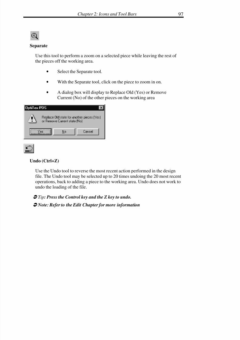
7/28/2019 OptiTex PDS User Manual
http://slidepdf.com/reader/full/optitex-pds-user-manual 121/727
Chapter 2: Icons and Tool Bars 97
Separate
Use this tool to perform a zoom on a selected piece while leaving the rest of
the pieces off the working area.
• Select the Separate tool.
• With the Separate tool, click on the piece to zoom in on.
• A dialog box will display to Replace Old (Yes) or RemoveCurrent (No) of the other pieces on the working area
Undo (Ctrl+Z)
Use the Undo tool to reverse the most recent action performed in the design
file. The Undo tool may be selected up to 20 times undoing the 20 most recentoperations, back to adding a piece to the working area. Undo does not work toundo the loading of the file.
! !! ! Tip: Press the Control key and the Z key to undo.
! !! ! Note: Refer to the Edit Chapter for more information

7/28/2019 OptiTex PDS User Manual
http://slidepdf.com/reader/full/optitex-pds-user-manual 122/727
Digitize, PDS & Grade Manual98
Redo (Ctrl+Y)
Use the Redo tool to reverse any operation changed by the Undo command.
Continue to choose the Redo tool until all of the “undone” operations havebeen reversed.
! !! ! Tip: Press the Control key and the Y key to redo.
! Note: Refer to the Edit Chapter for more information.
Cut (Ctrl + X)
Cut is used to cut a pattern piece from a file. The cut piece is transferred to the
clipboard and remains on the clipboard until another item is placed on the
clipboard. This tool is often used to cut one piece out of an existing design fileand paste it into another design file.
Copy (Ctrl + C)
Copy is used to copy a pattern piece from a file. The Copied piece istransferred to the clipboard and remains on the clipboard until another item is
placed on the clipboard. This tool is often used to copy one piece from an
existing design file and pastes it into another design file.

7/28/2019 OptiTex PDS User Manual
http://slidepdf.com/reader/full/optitex-pds-user-manual 123/727
Chapter 2: Icons and Tool Bars 99
Paste (Ctrl + V)
Paste is used to paste an item from the clipboard into another file. The Paste
command is used as a secondary step to either the Copy command or the Cutcommand.
Swap Pieces
Swap pieces exchanges a piece on the working area for the original piece in
the piece bar. This feature is used to compare the original piece (the piece inthe piece bar) with the piece that is being changed (the piece in the working
area) during the editing process.
Remove Current
Remove Current removes piece in the working area without updating theoriginal pieces. Use this option to clear the working area of all pieces without
keeping any edits.
! !! ! Note: Refer to the Clear Pieces section in the Edit Chapter for more
information.
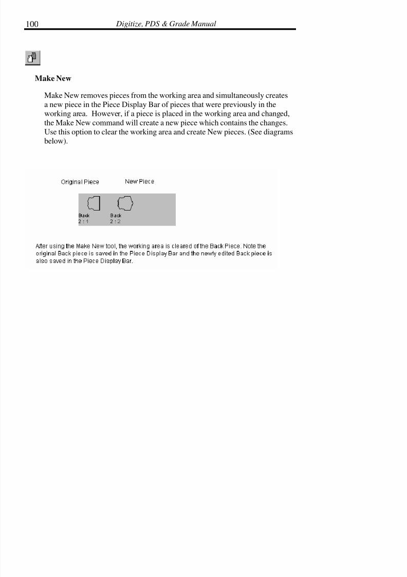
7/28/2019 OptiTex PDS User Manual
http://slidepdf.com/reader/full/optitex-pds-user-manual 124/727
Digitize, PDS & Grade Manual100
Make New
Make New removes pieces from the working area and simultaneously creates
a new piece in the Piece Display Bar of pieces that were previously in theworking area. However, if a piece is placed in the working area and changed,
the Make New command will create a new piece which contains the changes.
Use this option to clear the working area and create New pieces. (See diagramsbelow).

7/28/2019 OptiTex PDS User Manual
http://slidepdf.com/reader/full/optitex-pds-user-manual 125/727
Chapter 2: Icons and Tool Bars 101
! !! ! Tip: To place pieces that have been cleared back into the working area, use
the Undo command from the Edit menu.
Replace Old
Replace Old replaces the piece in the piece bar with the current piece on the
working area. Use this option to clear the working area of a selected piece
while updating the original piece with the newly edited piece. Using theReplace Old tool keeps the edits made to the selected piece.
! !! ! Note: Refer to the Clear Pieces section in the Edit Chapter for more
information.

7/28/2019 OptiTex PDS User Manual
http://slidepdf.com/reader/full/optitex-pds-user-manual 126/727
Digitize, PDS & Grade Manual102
The Advanced Toolbar
The Advanced Toolbar consists of tools used for Advanced Features in PDS,specifically, the Custom Fit Feature and the Fabric Feature. The Fabric feature
is covered in the Piece chapter and the Custom Fit feature is covered in the
Design chapter.
Hide Fabric Pattern
Hide Fabric Pattern hides a selected fabric pattern from display on the screen.
Show Fabric Pattern
Show Fabric Pattern shows a selected fabric pattern on the screen. The fabric
displays on the entire working area of the screen.
Clip Fabric Pattern
Clip Fabric Pattern shows the selected fabric only on the pieces that are
displayed in the working area of the screen.

7/28/2019 OptiTex PDS User Manual
http://slidepdf.com/reader/full/optitex-pds-user-manual 127/727
Chapter 2: Icons and Tool Bars 103
Show/Hide Control Points
This tool toggles between displaying the control points of a piece and not
displaying the control points of a piece. Fabric appearance is cleaner when thecontrol points are hidden from view.
The Dimensional Toolbar
The Custom Fit Toolbar gives you the right tools to take almost any kind of
garment and create a set of parameters, that by definition, if these parameters
will be changed, the specific garment will fit any customer measurements.
Horizontal Measurement Tool
The Horizontal tool is used to fix the Horizontal measurement between pair of
points to a specific distance. The distance can be set to any expression made of
numbers and body measurements, for example, an expression can be:Side_Seam+1 and means that the distance is the side-seam body measurement
plus one inch. The points must belong to the same pattern and can only be
points of the external contour (the current version supports custom fitting of external contour only, future versions will support internals as well).

7/28/2019 OptiTex PDS User Manual
http://slidepdf.com/reader/full/optitex-pds-user-manual 128/727
Digitize, PDS & Grade Manual104
In order to create a Horizontal Measurement:
Select the Horizontal tool, click on the 1st point, click on the 2nd point (one by
one, the order is not important,).
Drag the mouse to the place you want the rule to appear in and click again. An
Edit Dimension dialog will open.
In the Expression field of this dialog, enter the required Expression.
After you have added your expression, press OK. The new rule will appear onthe screen.
You can also take the Horizontal rule tool and add a new rule between points
which sets the vertical distance between them to 0.0 as they should align (pay
attention that we set the Horizontal distance to 0.0 and not the vertical
distance).
Vertical Measurement Tool
The vertical tool is used to fix the vertical measurement between pair of points
to a specific distance. The distance can be set to any expression made of numbers and body measurements, for example, an expression can be:
BACK_SHOULDER/2+1 and means that the distance is a half of the shoulder
to shoulder body measurement plus one inch. The points must belong to the
same pattern and can only be points of the external
Contour (the current version supports custom fitting of external contour only,
future versions will support internals as well).
7/28/2019 OptiTex PDS User Manual
http://slidepdf.com/reader/full/optitex-pds-user-manual 129/727
Chapter 2: Icons and Tool Bars 105
In order to create a Vertical Measurement:
Select the vertical tool, click on the 1st point, click on the 2nd point (one by
one, the order is not important).
Drag the mouse to the place you want the rule to appear in and click again. An
Edit Dimension dialog will open.
In the Expression field of this dialog, enter the required Expression.
After you have added your expression, press OK. The new rule will appear onthe screen.
You can also take the vertical rule tool and add a new rule between points
which sets the vertical distance between them to 0.0 as they should align (pay
attention that we set the vertical distance to 0.0 and not the horizontal
distance).
Diagonal Measurement Tool
The Diagonal Measurement tool is used to fix the diagonal measurement
between a pair of points to a specific distance. The distance can be set to anyexpression made of numbers and body measurements, for example, an
expression can be: SHOULDER/2 and means that the distance is the shoulder
measurement divided by 2. The points must belong to the same pattern andcan only be points of the external contour.
In order to create a Diagonal Measurement:
• Select the Diagonal tool from the Dimension toolbar.
• Click on the first point, and then click on the last point.

7/28/2019 OptiTex PDS User Manual
http://slidepdf.com/reader/full/optitex-pds-user-manual 130/727
Digitize, PDS & Grade Manual106
• Drag the mouse to the place on the screen where the rule shouldappear. Click again.
• An Edit Dimension dialog box will open. In the Expressionfiled of this dialog, enter the required Expression.
• After the Expression has been added, click OK. The new rulewill appear on the screen.
Curve Measurement Tool
The Curve Measurement tool is used to fix a curve measurement between a
pair of points to a specific distance. The distance can be set to any expressionmade of numbers and body measurements, for example, an expression can be:
ARMHOLE + ½ and means that the distance is the armhole measurement plus½ an inch. The points must belong to the same pattern and can only be pointsof the external contour.
In order to create a Curve Measurement:
• Select the Curve tool from the Dimension toolbar.
• Click on the first point, and then click on the last point.
• Drag the mouse to the place on the screen where the rule shouldappear. Click again.
• An Edit Dimension dialog box will open. In the Expression
filed of this dialog, enter the required Expression.
• After the Expression has been added, click OK. The new rulewill appear on the screen.
7/28/2019 OptiTex PDS User Manual
http://slidepdf.com/reader/full/optitex-pds-user-manual 131/727
Chapter 2: Icons and Tool Bars 107
The Accessories Toolbar
This toolbar contains a group of tools that you can use to manipulate pieces as
well as its segments.
Walk
The Walk tool is used to walk two pieces against each other. This tool is usedafter the pieces to be walked have been locked together on a shared point using
the Move (hand) tool.
! !! ! Tip: To back up one step, use the Undo command in the Edit menu or use
Ctrl + Z.
! !! ! Note: Refer to the Piece chapter for a detailed description of the Walk
feature.
Measure
Select the Measure tool to measure distances between any two points. The
points can be vertical, horizontal or diagonal.
To Measure Distances:
• Select the Measure tool.

7/28/2019 OptiTex PDS User Manual
http://slidepdf.com/reader/full/optitex-pds-user-manual 132/727
Digitize, PDS & Grade Manual108
• Click the point to begin the measurement.
• Move the cursor to the point where the measurement is to endand click the mouse.
• The All Dimension Values dialog box displays showing themeasurement.
• Click OK.
Trace Piece
Select the Trace tool to create a new pattern piece out of two or more pieces
laying on top of each other, thereby creating a conjunction of the pieces. Thistool traces the intersecting lines of the pieces in order to create a new piece.
(See the diagram below).
To Create a New Piece with the Trace Tool:
• Place the pieces to be joined overlapping in the working area.
• Select the TRACE tool.
• Click the mouse button on any point of the new perimeter. Thewhole piece becomes highlighted in red.
• Click the next point in a clockwise direction on the intersectingsegment from the second piece. The PDS software generates anew piece from the intersections of the original pieces
• Once all segments are traced, shown by the new formhighlighted in red, click the Trace tool on a blank area of the

7/28/2019 OptiTex PDS User Manual
http://slidepdf.com/reader/full/optitex-pds-user-manual 133/727
Chapter 2: Icons and Tool Bars 109
working screen.
• The newly created piece is displayed in the Piece Display Bar asan individual piece.
Join Pieces
The Join Piece tool is used to join two different pieces together as one along a
shared segment. If the two pieces have the same length and angle, they are
joined perfectly. If they do not have the same length and angle, and if the linesegments are not parallel, the pieces are joined, but their junction is not
perfect. It may be necessary to edit the intersecting lines on the newly joined
piece. Patterns may be cut multiple times and rejoined.
To Join Pieces:
• Select the Join Pieces tool.
• Click within one piece, near the segment where the pieces are to
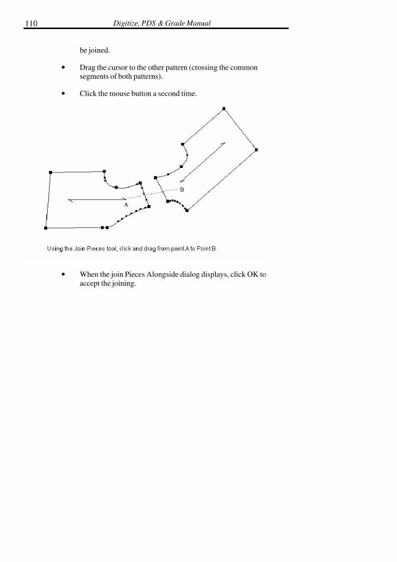
7/28/2019 OptiTex PDS User Manual
http://slidepdf.com/reader/full/optitex-pds-user-manual 134/727
Digitize, PDS & Grade Manual110
be joined.
• Drag the cursor to the other pattern (crossing the commonsegments of both patterns).
• Click the mouse button a second time.
• When the join Pieces Alongside dialog displays, click OK to
accept the joining.

7/28/2019 OptiTex PDS User Manual
http://slidepdf.com/reader/full/optitex-pds-user-manual 135/727
Chapter 2: Icons and Tool Bars 111
! !! ! Note: It is recommended to join two pieces at the beginning or end of a
segment. One point will always be shared by both pieces.
Join Pieces Dialog Box:
To join pieces into one single piece, unchecked the "Move Pieces Along SideOnly option
! !! ! Tip: Since the join pieces tool is joining two segments even if they do not
have the same length, the direction of pointing is important. The first
7/28/2019 OptiTex PDS User Manual
http://slidepdf.com/reader/full/optitex-pds-user-manual 136/727
Digitize, PDS & Grade Manual112
clicked piece becomes stationary and the second piece will move towards the first one. The joining point is the closest point right to the
line that is created by the join tool.
Delete Seam:
Select this option to delete the seam between the joined pieces, making the
joined pieces one individual piece.
Move Piece Along Side Only:
Select this option to move the pieces next to each other only, without deleting
the seam in between the pieces. The two pieces remain separate individualpieces.
Cut
Use the Cut tool to cut a piece. The Cut tool draws a line across the piece andsplits the piece along the line. The line may be a simple, two point’s line. Or it
may be a multi point curved line. The PDS software has the ability to
automatically grade the piece along the cut if grading is necessary. Thiseliminates figuring out difficult grading values.
To Cut a Piece:
• Select the Cut tool.
• Click the mouse on the boundary of the piece where the cut is tobegin.
• When the Move dialog box displays, either enter values tospecify the exact location of the first point, or press OK or the

7/28/2019 OptiTex PDS User Manual
http://slidepdf.com/reader/full/optitex-pds-user-manual 137/727
Chapter 2: Icons and Tool Bars 113
Enter key to bypass this dialog box.
• Click the mouse where the next point of the cut line is to beplaced. Repeat steps #3 and step #4 until the cut line reaches
another boundary line of the piece.
• When the dialog box displays asking, “Do you want to aligncutting by base size?”select NO to automatically grade along the
cut, or select YES not to grade the cut.
• When the Seam Attributes dialog box displays, enter the desiredseam width and corner types
• Click OK.
! !! ! Tip: To create a curved cut line, hold the Shift key down when clicking the
mouse to select a point.
! !! ! Tip: If you need to cut the piece along a known angle you can use the F2
key just after you clicked the first (start) point of the piece.
Draft
Use the Draft tool to draft multi point internal lines.
To Draft a Line:
• Select the Draft tool.
• Click the mouse anywhere on the selected piece.
• When the Add A Contour Relative To Current Point dialog boxdisplays, enter specific values for exact placement of the point

7/28/2019 OptiTex PDS User Manual
http://slidepdf.com/reader/full/optitex-pds-user-manual 138/727
Digitize, PDS & Grade Manual114
or select OK to bypass this dialog.
• Repeat Steps #2 and #3 until the desired line is constructed.
• To finish drafting the line, click the right mouse button andselect Finish Draft from the pop up menu.
! !! ! Tip: To create a curved cut line, hold the Shift key down when clicking the
mouse to select a point.
Cut Along Internal
Use Cut Along Internal to cut (split) a piece along an existing internal line.The internal line has to start and end exactly on the pieces external perimeter
line.
To Cut Along an Internal:
• Select the Cut Along Internal tool.
• Click the mouse somewhere along the internal line where thepiece is to be cut.
• When the dialog box displays asking, “Do you want to aligncutting by base size?, select NO to automatically grade along the
cut, or select YES not to grade the cut.
• When the Seam Attributes dialog box displays, enter the desiredseam width and corner types.
• Click OK.

7/28/2019 OptiTex PDS User Manual
http://slidepdf.com/reader/full/optitex-pds-user-manual 139/727
Chapter 2: Icons and Tool Bars 115
Trace Segments
Trace Segments is used to trace segments from an existing piece in order to
create a new piece. For example, this tool is often used to create facing andlining pattern pieces. It is possible to use the trace tool to create a new piecefrom two existing pieces.
To Trace Segments:
• Select the Trace Segments tool.
• Click the mouse on each line segment from which to create thenew piece. Select line segments in the clockwise direction. Eachsegment highlights in red during the selection process and an
‘X’ mark will appear on the next grading point.
• When all segments are selected (a closed contour shape has beendefined), a dialog box displays asking, “Finish form contour?”.
Click YES to complete the tracing procedure. Click NO to
continue tracing, or click CANCEL to cancel the procedureentirely.
• The new piece appears on top of the original piece. Use theMove (hand) Tool to move the new piece away from the original
piece.

7/28/2019 OptiTex PDS User Manual
http://slidepdf.com/reader/full/optitex-pds-user-manual 140/727
Digitize, PDS & Grade Manual116
! !! ! Note: When you use the draft tool and you want to zoom out, click on the
mouse right button. From the menu that will appear, click on “Select
Tool” with the mouse left button + Ctrl key!
! !! ! Note: To delete the line, select the line with the pointer tool and press the
Delete key. Or, select the line with the pointer tool and select Delete Internal Elements from the Edit menu. Another way to delete the
line is to use the Undo tool, the Undo command in the Edit menu, or press Ctrl + Z.
Build Piece
Build piece is used to build pieces from an existing pieces in order to create a.
pattern pieces. It is possible to use the trace tool to create a new piece fromtwo existing pieces.
7/28/2019 OptiTex PDS User Manual
http://slidepdf.com/reader/full/optitex-pds-user-manual 141/727
Chapter 2: Icons and Tool Bars 117
To Built piece:
• Select the built piece tool.
• Click the mouse on the first area for the new piece. The closedcounter will be highlight.
• Click the mouse on the next area to be joined to the new piece
• The counter of the new piece will highlight.
• In order to place the build piece click on the selected area again.
• The new piece appears on top of the original piece. Use theMove (hand) Tool to move the new piece away from the original
piece.
Fold Out
Use the Fold out tool to fold out part of a pattern piece. This toll is commonly
used to make pattern pieces with attached facings.
To Use the Fold Out Tool:
• Create an internal line on the pattern piece using the MakeParallel command in the Design Menu. (see the Design
Chapter).
• Click on the Fold Out tool.
• Click on the mirror line of the pattern piece. (see the diagrambelow).

7/28/2019 OptiTex PDS User Manual
http://slidepdf.com/reader/full/optitex-pds-user-manual 142/727
Digitize, PDS & Grade Manual118
• Click on the newly added internal fold line.
• Delete unnecessary internal lines. (See the diagram below toreview the new pattern piece with the fold out facing).

7/28/2019 OptiTex PDS User Manual
http://slidepdf.com/reader/full/optitex-pds-user-manual 143/727
Chapter 2: Icons and Tool Bars 119
Fold In Tool
Allows the user to fold the patterns on a selected line in order to check
symmetric pieces.
• Select the Fold In icon.
• Highlight the segment(s) to fold in by clicking and dragging in aclockwise manner.
• The Move Point dialog box will appear in order to confirm theend of the segment.
• Click OK.
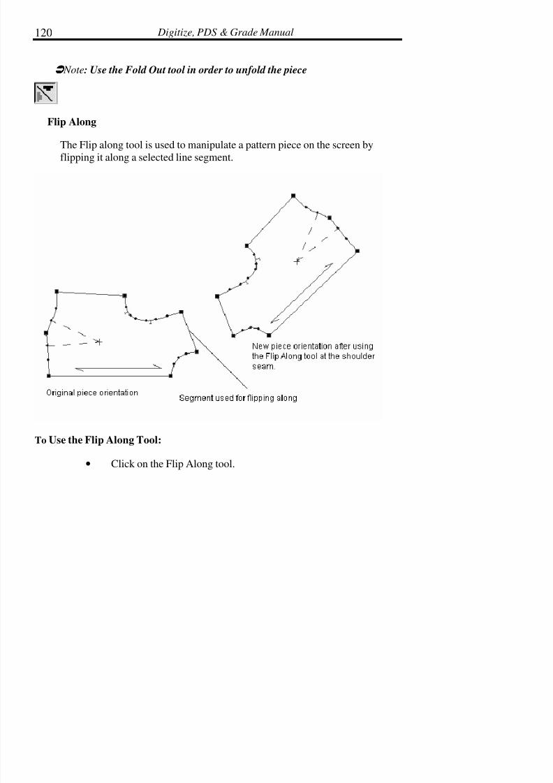
7/28/2019 OptiTex PDS User Manual
http://slidepdf.com/reader/full/optitex-pds-user-manual 144/727
Digitize, PDS & Grade Manual120
! !! ! Note: Use the Fold Out tool in order to unfold the piece
Flip Along
The Flip along tool is used to manipulate a pattern piece on the screen by
flipping it along a selected line segment.
To Use the Flip Along Tool:
• Click on the Flip Along tool.

7/28/2019 OptiTex PDS User Manual
http://slidepdf.com/reader/full/optitex-pds-user-manual 145/727
Chapter 2: Icons and Tool Bars 121
• Click on the segment where the piece is to be flipped along.
• Click on the center of the piece.
Swap Segment
Allows the user to swap between internal segment and external segment.
• Select the Swap Segment tool.
• Click on the first point of the external segment.
• Click on the last point of the external segment.
•
Click on the first point of the internal segment.
• Click on the last point of the internal segment.
• The Swap Segments of Contours dialog box will appear. Selectthe desired information.
First Points Swap/Last Points Swap

7/28/2019 OptiTex PDS User Manual
http://slidepdf.com/reader/full/optitex-pds-user-manual 146/727
Digitize, PDS & Grade Manual122
Substitute – Switches the internal line with the external line.
Extrapolation – Keeps the internal line an internal, makes the external line an
internal, and draws external lines from their end points until the lines cross.
Choose Segments Dialog Box
The Choose Swap Segments dialog box allows the option to shorten orlengthen the selected line. Contour Segment is the external line. Segment to
Swap is the internal line.
• Select Choose Segments in the Swap Segments of Contoursdialog box.
• Under the Point section, choose which point to move.
• Click the Shift Point buttons in order to move the selection of
the line.
• Click OK.
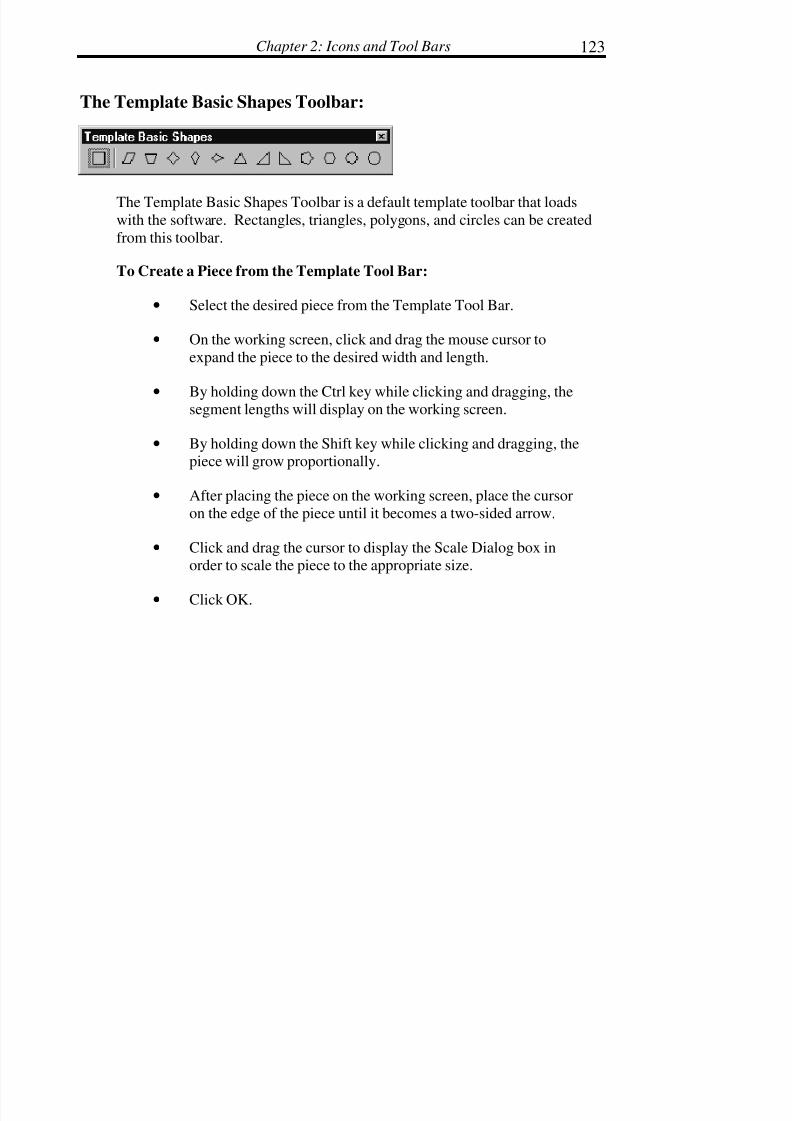
7/28/2019 OptiTex PDS User Manual
http://slidepdf.com/reader/full/optitex-pds-user-manual 147/727
Chapter 2: Icons and Tool Bars 123
The Template Basic Shapes Toolbar:
The Template Basic Shapes Toolbar is a default template toolbar that loads
with the software. Rectangles, triangles, polygons, and circles can be created
from this toolbar.
To Create a Piece from the Template Tool Bar:
• Select the desired piece from the Template Tool Bar.
• On the working screen, click and drag the mouse cursor to
expand the piece to the desired width and length.
• By holding down the Ctrl key while clicking and dragging, thesegment lengths will display on the working screen.
• By holding down the Shift key while clicking and dragging, thepiece will grow proportionally.
• After placing the piece on the working screen, place the cursoron the edge of the piece until it becomes a two-sided arrow.
• Click and drag the cursor to display the Scale Dialog box inorder to scale the piece to the appropriate size.
• Click OK.
7/28/2019 OptiTex PDS User Manual
http://slidepdf.com/reader/full/optitex-pds-user-manual 148/727
Digitize, PDS & Grade Manual124
The Template Toolbar:
Template Toolbar can be created from the template libraries to display those
pieces in the template file.
To Create a Piece from the Template Toolbar:
• Select the desired piece from the Template Tool Bar.
• On the working screen, click and drag the mouse cursor toexpand the piece to the desired width and length.
• By holding down the Ctrl key while clicking and dragging, thesegment lengths will display on the working screen.
• By holding down the Shift key while clicking and dragging, the
piece will grow proportionally.
• After placing the piece on the working screen, place the cursoron the edge of the piece until it becomes a two-sided arrow.
• Click and drag the cursor to display the Scale Dialog box inorder to scale the piece to the appropriate size.
• Click OK.

7/28/2019 OptiTex PDS User Manual
http://slidepdf.com/reader/full/optitex-pds-user-manual 149/727
Chapter 3: File Menu 125
Chapter 3: File Menu
The commands available in the File Menu are used for bringing files into and
out of the PDS program. The File menu is also used to print, plot, and digitize.
To select one of the File menu commands, select the command in the pulldown menu and press the left mouse button, or use the shortcut listed in
parentheses next to the command in the pull down menu. Commands may also
be selected by using the corresponding tool icon displayed on the Standard
Tool Bar.
New (Ctrl+N):
The New command is used when creating a new style (DSN) file. A DSN filecontains all the patterns necessary to make one complete item. Pieces are
added to a style file by digitizing pieces, drafting from scratch, or merging and
editing pieces from existing style files. The number of pieces in a DSN file islimited only by the amount of memory available on the computer.
To Start a New File:
• From the File menu select New, press CTRL+N, or click on theNew icon from the toolbar. The Make Rectangle dialog box is
displayed.
• Enter the desired values for the length and width of the rectangle.
! !! ! Note: The Cancel button may be used to bypass the Make Rectangle dialog box.
• Click OK.
7/28/2019 OptiTex PDS User Manual
http://slidepdf.com/reader/full/optitex-pds-user-manual 150/727
Digitize, PDS & Grade Manual126
The new piece is displayed in the Piece Display Bar. The new DSN file is
“Untitled.” To save the file, choose the Save or Save As commands from theFile menu.
! !! ! Note: Only one DSN file can be opened at a time. The last 4 opened files
are displayed at the bottom of the File menu.
Open (Ctrl+O)
Use the Open command to open an existing style (DSN) file. A DSN file
contains all the pattern pieces necessary to make one complete item.
No more than one file may be opened at a time. If a DSN file is currently openand the Open command is chosen, the Save Current Changes dialog box is
displayed. Select Yes to save the changes and close the current file or select
No to close the file without saving any of the changes.
! !! ! Note: The last directory where style files have been saved becomes the default directory for the Open and Save commands.
To Open a File:
• From the File menu select Open, press CTRL+O or click on theOpen icon on the tool bar. The Open dialog box is displayed.
• OPTIONAL: Change to a different drive and/or directory to findthe desired file.
• Select the desired file from the File List dialog box.
• Click OK.
! !! ! Tip: Double click on the file name to quickly open the file instead of using
the OK button.

7/28/2019 OptiTex PDS User Manual
http://slidepdf.com/reader/full/optitex-pds-user-manual 151/727
Chapter 3: File Menu 127
Open Dialog Box:
File List and File Name Dialog Box
The File List field displays the DSN files that exist in the current drive and
directory. If there is more information than fits in the box, use the scroll bars
to scroll up and down the list. The File Name field remains empty until a file is
selected. Once a file is selected, the selected file is displayed in the File Namefield and if available a preview is displayed in the Preview field to the right.
! !! ! Note: You can also open OptiTex Modulate files (*. cus) directly from
OptiTex PDS open dialog box, just change the file type to *.cus!
Drive and Directory
To change to another directory, click on the arrow to the left of the Look In
field to display a list of the directories or click on the Up One Level icon tomove up one folder. If there is more information than what fits in the field, use
the scroll bars to scroll up and down the list.

7/28/2019 OptiTex PDS User Manual
http://slidepdf.com/reader/full/optitex-pds-user-manual 152/727
Digitize, PDS & Grade Manual128
Options
The Open button loads the selected file, whereas the Cancel button exits the
Open dialog box without loading a file. If running Windows for Workgroups,click on the Network button to display the Connect to Network Drive dialog
box.
Merge Style File
Use the Merge DSN File command to load an existing style file into the
current style file.
The merged style file receives all the size characteristics of the already open
style file. If the merged file does not have the same number of sizes or thesame size names as the open file, the merged file automatically takes on the
sizes and size names of the current DSN file (regardless of base size or other
parameters).
To Merge Files:
• From the File menu select Merge Style Files. The Open dialogbox is displayed.
• Select the desired file from the File List box.
• Click Open.
! !! ! Note: The number of pattern pieces in any Style file is limited only by the
amount of memory available on the computer.There are cases when the merged file creates strange grading on a single piece
in the working area. A dotted rectangle displays over the top of the piece witha small black dot. Simply reset the grading on the piece to zero (0) and begin
the grading process again.

7/28/2019 OptiTex PDS User Manual
http://slidepdf.com/reader/full/optitex-pds-user-manual 153/727
Chapter 3: File Menu 129
To Reset the Grading on a Piece:
1. From the View menu select Grading Table.
2. Move the cursor to the top of the X column until the standard
select tool (arrow pointer) changes to a black downward arrow.
Now click the left mouse button to select the entire X column.
• From the Grading Menu select Zero X Grading. All values in theX column should now be zero. Repeat steps 2 and 3 for the Y
column, except select Zero Y Grading.
• Use the copy and paste commands in the grading table to changethe values on all grading points to zero 0.
• Re-grade the piece.
! !! ! Note: Grading commands are covered in detail in the Grading menu.
How to use the "Merge Style Files" dialog box:
The merge style files dialog enables the user to select the desired size listaccording to the current size list and the merges size list:
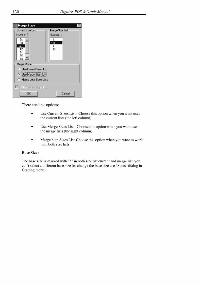
7/28/2019 OptiTex PDS User Manual
http://slidepdf.com/reader/full/optitex-pds-user-manual 154/727
Digitize, PDS & Grade Manual130
There are three options:
• Use Current Sizes List - Choose this option when you want usesthe current lists (the left column).
• Use Merge Sizes List - Choose this option when you want usesthe merge lists (the right column).
• Merge both Sizes List-Choose this option when you want to work with both size lists.
Base Size:
The base size is marked with "*" in both size list current and merge list, you
can't select a different base size (to change the base size use "Sizes" dialog inGrading menu).

7/28/2019 OptiTex PDS User Manual
http://slidepdf.com/reader/full/optitex-pds-user-manual 155/727
Chapter 3: File Menu 131
Variation grading:
The "Delete variation grading" is enabled only if one of the style files (current
or the merge) has variation grading, only then can you choose to delete sizes:
History
The History command enables the user to save additional information witheach Style file. This information enables the user to follow up or to retrieve the
positioning of a file at a specific point of time. This allows the company to
create a History Log for each style and tracks the changes to a file according todates. Two options are offered. One enables the user to add text description
comments to the file, the second option enables the user to make a file
generation with the ‘Save Version’ command allowing the possibility in thefuture to retrieve the file layout at certain stages of the design process.

7/28/2019 OptiTex PDS User Manual
http://slidepdf.com/reader/full/optitex-pds-user-manual 156/727
Digitize, PDS & Grade Manual132
To Enable the History Command:
• Select History from the File menu and activate (check)Automatically Save History on Close.
• Click the Close button to leave the History dialog box.
• The Save History dialog will open on every Save command.Comment may be typed in addition to saving the file with all the
information as it is at the moment of the Save command.
To Save History:
• The History dialog box is displayed when a file is saved.
• The date and user name is automatically noted.

7/28/2019 OptiTex PDS User Manual
http://slidepdf.com/reader/full/optitex-pds-user-manual 157/727
Chapter 3: File Menu 133
• Type comments in the comment field.
• OPTIONAL: Save graphic information by activating (checking)the Store Version field.
• Click OK.
At any point of time History may be selected from the File Menu to view any
comments attached to the file. Delete messages by clicking the Delete button.
! !! ! Note: If a specific layout is saved with the file, the size of the file is going
to be much larger and might cause a delay during File Open. Do
not save information that will not be used, or delete it before the final save.

7/28/2019 OptiTex PDS User Manual
http://slidepdf.com/reader/full/optitex-pds-user-manual 158/727
Digitize, PDS & Grade Manual134
File Finder
Find and Update command
This application finds style (DSN) files and pieces in OptiTex PDS. After
finding, the file can be opened or updated according to the style file.
In order to use the Find and Update application select the File Finder
command from the File menu.
! !! ! Note: The Find and Update application is also available in OptiTex Mark.
Find
After setting all search parameters, click on the Find button. The found itemswill display at the bottom of the dialog box. There are two items that can be
found – Style Files or Pieces in a Style File.
These two choices affect what will display in the list of found items at the
bottom of the dialog box. For example, a search for pieces with a name
beginning with “BA” with the selected item to find as Piece, will result in a listof all files containing pieces with a name beginning with “BA” . The same file
might be listed a few times, because it has several pieces beginning with a
matching name. If the item to find is a Style File, the file will display onlyonce even though it has several pieces with a matching name.
! !! ! Note: The file finder supports “Regular Expression” (*.*)

7/28/2019 OptiTex PDS User Manual
http://slidepdf.com/reader/full/optitex-pds-user-manual 159/727
Chapter 3: File Menu 135
Find Tab:
The main function of the Find Tab is to look for Style (DSN) files according to
the OptiTex application it is launched from. When working from the PDS
application, it will manage Style Files and Pieces within the Style Files. While
looking for a style file in the PDS application, the Find dialog box enables theuser to input further search filters, such as Style name, Piece name, Material
type, Piece Description, etc.
7/28/2019 OptiTex PDS User Manual
http://slidepdf.com/reader/full/optitex-pds-user-manual 160/727
Digitize, PDS & Grade Manual136
! !! ! Note: Click on the small arrow with the mouse left click to open a drop list
of the previous fields names or use the mouse right button to open
utility box for editing the previous fields names list:
Search Options:
Style File
Type a file name to search for specific Style Files by file name.
Look in
This field defines the scope of the search to specific directories or subdirectories.
Show file name only
Once the Show File Name Only is checked, the finder will look only for
*.DSN file. Otherwise, when unchecked, the finder will look for pieces from*.DSN files.
! !! ! Note: Whenever this command is unchecked, “Replace Piece” and
“Delete Piece” in the Update property page will be enabled and vice
versa.
Look in sub folders
This option extends the search to sub folders.
Filters:
Piece Name filter
Use this option as a filter. Type the piece name to limit the search to files thatcontain a specific piece.

7/28/2019 OptiTex PDS User Manual
http://slidepdf.com/reader/full/optitex-pds-user-manual 161/727
Chapter 3: File Menu 137
Piece Code filter
Use this option as a filter. Type a piece code to limit the search to files that
contain a specific piece code.
Piece Description filter
Use this option as a filter. Type a piece description to limit the search to files
that contain a specific piece description.
Material filter
Use this option as a filter. Type a material to limit the search to files thatcontain a specific material.
Style Name filter
Use this option as a filter. Type a Style Name to limit the search to a specificstyle name.
Match case
When this option is selected the program will find only files that match thecase of the characters in the piece name, style name, file name and material
exactly. Otherwise, the command will finds files with either uppercase or
lowercase characters that match the characters in the piece name, style filename and material strings.
Match whole word only
When this option is selected the program will find only files that match thespecified piece name, style name, file name and material with no extra
characters. Otherwise, the command matches any string, whether it is a
fragment of a larger string or not.

7/28/2019 OptiTex PDS User Manual
http://slidepdf.com/reader/full/optitex-pds-user-manual 162/727
Digitize, PDS & Grade Manual138
Options:
Find now
Click this button to activate the search process.
Open file
Click this button to open the selected files in the OptiTex PDS program.
Select All
Click this button to select all the files in the current file list.
Stop
Click this button to halt the search operation and return control to the user.
Maximize
Click this button to enlarge the Find & Update dialog box to maximum size.
Cancel
Click this button to quit Find and return to the host application.
! !! ! Note: All the parameters entered during the search are saved in the ini
file. This allows you to utilize existing data without having to retype the data.
Select Tab:
The Select Tab enables you to select and mark the chosen or current piece tocopy or replace in other files. It is also possible to click the Get Style File
button to access the file that is currently marked in the search list (It will be in
gray color). The piece names and pieces will be displayed. The Open button
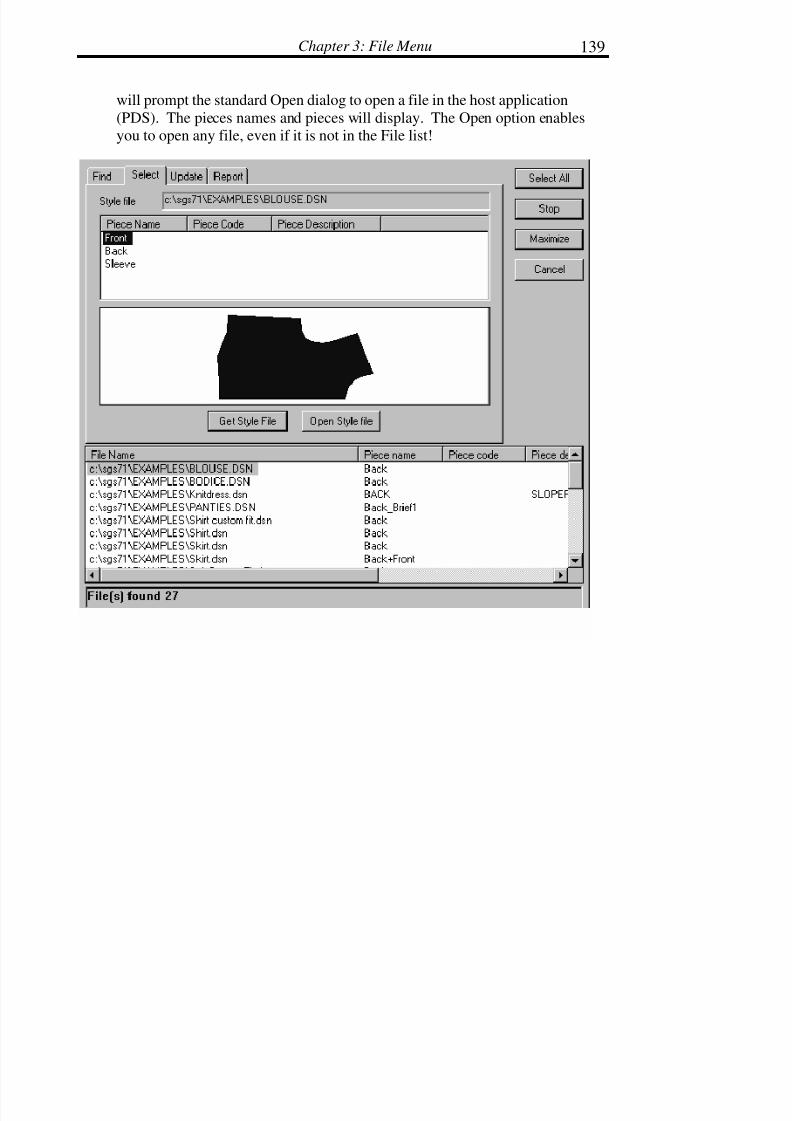
7/28/2019 OptiTex PDS User Manual
http://slidepdf.com/reader/full/optitex-pds-user-manual 163/727
Chapter 3: File Menu 139
will prompt the standard Open dialog to open a file in the host application
(PDS). The pieces names and pieces will display. The Open option enablesyou to open any file, even if it is not in the File list!

7/28/2019 OptiTex PDS User Manual
http://slidepdf.com/reader/full/optitex-pds-user-manual 164/727
Digitize, PDS & Grade Manual140
Options:
Get Style File
Click this button to load the selected style file from the file list. The selected
file will be the source file.
Open
Click this button to open a style file.
Update Tab
The Update tab is used in connection with the Select tab. Files may be
updated by adding pieces to a file, replacing a piece in a file, or updating an
existing piece in a file. Multiple files may be selected from the File list to beupdated.
To Add a Piece:
• First select the target files in the File list.
• Select a piece in the source file by using the Select Tab.
• Click on the Add Piece button.
• The piece from the source file is added to the target file or files inthe File list.
Repeat as above for Replace Piece and Delete Piece clicking on theappropriate buttons.
! Note: The Update tab can not be used until a source file has been chosen
using the Select Tab.

7/28/2019 OptiTex PDS User Manual
http://slidepdf.com/reader/full/optitex-pds-user-manual 165/727
Chapter 3: File Menu 141
Add Piece
Click on this button to add the selected piece in the Select Tab to the currentstyle file, selected in the File list.

7/28/2019 OptiTex PDS User Manual
http://slidepdf.com/reader/full/optitex-pds-user-manual 166/727
Digitize, PDS & Grade Manual142
Replace Piece
Click on this button to replace the selected piece in the Select Tab to the
current style file, selected in the File list.
Delete Piece
Click on this button to delete the piece selected in the file selected in the File
list.
Report Tab
The Report Tab prepares a report describing the contents of one or more DSNin ASCII (text) format. This report can be imported into applications such as
Word, Excel, Lotus 1-2-3 and Access, for editing and/or printing.

7/28/2019 OptiTex PDS User Manual
http://slidepdf.com/reader/full/optitex-pds-user-manual 167/727
Chapter 3: File Menu 143
Append File
When the Append File checkbox is selected, the report will be added to the
end of an existing report file, rather than create a new file.
Report File Name
This field is used to specify a new file name for the created report, or choose
an existing file name for appending the report.
7/28/2019 OptiTex PDS User Manual
http://slidepdf.com/reader/full/optitex-pds-user-manual 168/727
Digitize, PDS & Grade Manual144
Report to Data Base
Click this button to create a report from the currently selected style file and
then, save it under the specified file name.
Save
The Save command saves the file displayed on screen with the current filename in the specified drive and directory. To ensure that a file is saved with
the correct options, use the Save As command to save the file the first time.
The last directory where design files have been saved becomes the defaultdrive for the Open and Save commands.
! !! ! Note: The DSN extension is added to the file name automatically.
To Save a File:
• From the File menu choose Save or click the Save icon on the toolbar.
! !! ! Tip: It is a good habit to periodically save files while working. Use the
Save command or Ctrl + S every ten to twenty minutes to prevent
loss of data in the event that the computer improperly shuts downwhile working.
7/28/2019 OptiTex PDS User Manual
http://slidepdf.com/reader/full/optitex-pds-user-manual 169/727
Chapter 3: File Menu 145
Save As
The Save As command is used to save a file for the first time to ensure the
current file name and paths are specified. Save As can also be used to save thecurrent file under a different name. For example, if a user wants to create a
new design based on an existing design, the existing design may be saved as adifferent name. The original design file still exists under its original name anda replica exists under a new name.
To Save As:
• From the File menu select Save As. The Save As dialog box isdisplayed.
• OPTIONAL: Select the desired drive and directory to save thefile.
• In the File Name field, type the name of the file.
! !! ! Note: The .DSN extension is automatically added to the file name. File names are limited to eight alphanumerical characters or less.
• Click SAVE.
If the name of the file already exists, a dialog box will ask to overwrite the file.Click Yes to overwrite, click No to enter a new name.
! !! ! Note: You now have the option to save the file in Version 7.3 format!

7/28/2019 OptiTex PDS User Manual
http://slidepdf.com/reader/full/optitex-pds-user-manual 170/727
Digitize, PDS & Grade Manual146
Save As Dialog Box:
! !! ! Note: You can save DSN files in OptiTex Modulate format (CUS
extension) by changing the saving files types to *.CUS
Save In
The Save In field lists the current drives and directories that may be selected.
To change to another directory, double click the first option (usually C:\) and alist of directories will display. If there is more information than what fits in the
current box, use the scroll bars to scroll up and down the list.
File Name and File List Box
The File Name box field remains empty until a file name is typed. The file
type will default to DSN unless a different file format has been selected. The
File List field displays the DSN files that exist in the current directory. If thereis more information than what fits in the current file list box, use the scroll
bars to scroll up and down the list.

7/28/2019 OptiTex PDS User Manual
http://slidepdf.com/reader/full/optitex-pds-user-manual 171/727
Chapter 3: File Menu 147
Save As Type
This drop down field determines what types of files will display. This option
defaults to .dsn in PDS.
! !! ! Note: SGS software only opens DSN files. To open any other type of file,
the Merge or Import commands must be used.
Digitize
Digitizing is the process of using a digitizing tablet and cursor to enter a
handmade paper pattern into the computer. A digitizing tablet is an electronic
board. SGS software supports many different brands and sizes of digitizingtablets.
SGS software has drivers for several main digitizer formats on the market
today, including Summagraphic, Numonics, Calcomp, and GTCO.
There are 3 main steps to configuring Digitizers for use with the SGS
software: 1) Configuring the digitizing tablet, 2) Configuring the serial port
communications through Windows, 3) Configuring the digitizer in SGSsoftware.
1. Configuring the Tablet
There are two main modes: ASCII mode and binary mode. Large scaledigitizers with 16-button cursor are in ASCII mode. Small digitizers, usually
with 4-button cursor, use BINARY mode.
The internal working units for the digitizer are defined as inches, which isusually set as Default by the manufacturer. The digitizing mode for alldigitizers is Point Mode.
Enable the <CR> and Line Feed. Digitizer should be set up in Remote mode.
7/28/2019 OptiTex PDS User Manual
http://slidepdf.com/reader/full/optitex-pds-user-manual 172/727
7/28/2019 OptiTex PDS User Manual
http://slidepdf.com/reader/full/optitex-pds-user-manual 173/727
Chapter 3: File Menu 149
Tips
It is recommended that SGS software users purchase a 16 button digitizing
cursor to speed the digitizing process.
SGS software uses its own internal digitizer drivers. Do not use the driversprovided by the digitizer manufacturers when using SGS software.
The windows program Terminal can be used to check that the comport anddigitizer are communicating. When using the terminal program, the digitizer
coordinates should display on the screen. The digitizer manufacturers usually
provide a program to check that the comport and digitizer are communicating.
Digitizer installation:
Make sure your digitizer is installed and turned on. SGS supplies the
installation software and driver for all digitizers it supports. Do not install
software, which comes with your digitizer!
Using the 40” X 60” Digitizing Tablet
This tablet sometimes requires additional configuration processes. Test to seeif the digitizer is working by opening the SGS digitizing screen in the PDS
program by selecting Digitize from the File menu. Try to digitize a basic
shape using the #1 and #2 button (see diagram below). Tape an 8.5 X 11”sheet of paper to the tablet for testing purposes. If nothing appears on the
digitizing screen on the computer while digitizing a basic shape, follow the
steps below.
! !! ! Note: Make sure the 16-button cursor is activated before attempting to
digitize. The cursor is active when the proximity light is yellow-
green at the top center of the tablet. If this light is red, place the
cursor on the tablet and press the #1 button. The red light should now be yellow-green.

7/28/2019 OptiTex PDS User Manual
http://slidepdf.com/reader/full/optitex-pds-user-manual 174/727
Digitize, PDS & Grade Manual150
The shape that you are attempting to digitize should appear on the digitizing
screen on the computer as you digitize each point.
• Insert the Numonics diskette into drive A:
• Type in A: and press <enter>.
• Type CD UTILITY and press <enter>.
• Type ASC COM1:9600,E,7,2 <enter>. *If the digitizer is pluggedinto COM2, use COM2 in place of COM1.
• Place the 16 button cursor on the digitizer tablet and press the #1key. The Proximity light at the top center of the tablet should turn
from red to yellow-green
• Touch any letter key on the keyboard.
• Move the 16-button cursor around on top of the tablet. Thecomputer screen should scroll a list of coordinates as the cursor
moves. If the coordinates appear on the computer screen, the
board should now work with SGS software.
• Exit the Numonics program. Use the backslash (\) key.
• Open the PDS program and open the digitizing screen. Try to
digitize a basic shape using the #1 and the #2 keys on the 16
button cursor.

7/28/2019 OptiTex PDS User Manual
http://slidepdf.com/reader/full/optitex-pds-user-manual 175/727
Chapter 3: File Menu 151
• If the board still does not respond, repeat the section above“Configuring the Tablet.”
Attaching the Digitizer Panel:
The digitizer panel contains all the piece attributes and information found in
the Piece Info dialog box. Using the Digitizer panel eliminates the need toenter the relevant attributes and information into the Piece Info dialog box.
The user can customize the digitizer panel. See Edit Panel found in the
Digitizer Setup dialog box.
• Tape a print out of the Digitizer Panel onto the Digitizing Tablet.The digitizer panel can be printed using Edit Panel found in theDigitizer Setup dialog box.
• Select Digitize from the File menu. The digitizer dialog boxdisplays.
• Using the mouse, select Panel Pos from the digitizer dialog box.
• Place the digitizer cursor in the lower left-hand corner of the
digitizer panel and press button number 1.
• Place the digitizer cursor in the upper right hand corner of thedigitizer panel and press button number 1.
A gray rectangular area will display in the digitizer dialog box; this areaillustrates the panel position on the digitizer tablet.
Attaching the digitizer menu:
If the digitizer cursor has only four buttons, a digitizer menu may help if it isattached to the digitizer tablet. The digitizer menu enables the user to define
the location of various point types, notches, buttons, internal lines, etc. When
using a sixteen-button cursor, the digitizer menu is not needed.

7/28/2019 OptiTex PDS User Manual
http://slidepdf.com/reader/full/optitex-pds-user-manual 176/727
Digitize, PDS & Grade Manual152
• Make a rectangle with 11 equally sized rows. The rectangle(digitizer menu) should consist of the following 11 rows; Point,Grade, Notch, Button, Line, Circle, Grd/Crv, Ngrd/Crv, Dart,
Contour and Baseline.
•
Tape the newly created Digitizer Menu onto the Digitizing Tablet.
• Select Digitize from the File menu. The digitizer dialog box isdisplayed.
• Using the mouse, select Menu Pos from the digitizer dialog box.
• Place the digitizer cursor in the lower left-hand corner of the
digitizer menu and press button number 1.
• Place the digitizer cursor in the upper right hand corner of thedigitizer menu and press button number 1.
A gray rectangular area will display in the digitizer dialog box; this areaillustrates the menu position on the digitizer tablet.
Preparing patterns for digitizing:
Before digitizing a pattern, mark or note the following items on the patternpieces.
• Grade points and/or grade rule numbers. This is only necessary if the patterns are going to be graded.
• Baseline or Grainline. The baseline is used to determine how thepiece is positioned on the screen.
• Notches. Not all the patterns have notches.
• Button or drill holes. Not all the patterns have drill holes

7/28/2019 OptiTex PDS User Manual
http://slidepdf.com/reader/full/optitex-pds-user-manual 177/727
Chapter 3: File Menu 153
• Internal lines and internal elements. Not all the patterns haveinternal lines or elements.
• Darts. Not all the patterns have darts. The dart should be markedwith 4 points. Three of the four points are on the boundary line,
the beginning, end, and middle of the dart. The fourth point is theapex or depth of the dart.
• Any Piece Information that the user would like to enter using thedigitizer panel, for example piece name, piece description,
quantity, and flip restrictions.
To Digitize:
• OPTIONAL: Display the grading table. The base size in thegrading table should be the size of the piece being digitized.
! !! ! Note: If the size is not defined in the grading table, the SGS software defaults to the size name base. The size name can be changed to
another name some other time.
• Attach the prepared pattern onto the digitizer tablet using drafting
tape. Pattern pieces can be taped to the digitizer tablet in any
direction, or even on top of each other. The baselineautomatically straightens the piece when displayed on the screen.
! !! ! Note: Drafting Tape is easier to remove from the digitizing tablet and
paper patterns. Rather than using tape, some users prefer to use a
big sheet of clear vinyl or plastic to hold pieces in place.
• From the File menu select Digitize to display Digitizer dialogbox. The digitizer dialog box is divided into three sections. Theleft section contains digitizer commands used with a four-button
digitizer. The right section is a scaled down view of the digitizing
tablet. The bottom section assigns a number to each button on the

7/28/2019 OptiTex PDS User Manual
http://slidepdf.com/reader/full/optitex-pds-user-manual 178/727
Digitize, PDS & Grade Manual154
digitizer cursor.
• Digitize the piece perimeter in the clockwise direction usingcorrect cursor buttons to achieve the shape desired. Always close
the perimeter by using button number 2 on the digitizer cursor.SGS recommends the user always begin digitizing at the bottom
left hand corner of each piece. The first point digitized will be
assigned point #1 but can be changed in the system later.
• After the piece boundary has been digitized and closed, thefollowing elements can be digitized in any order.
Baseline:
The Baseline or Grainline must be digitized after the piece perimeter. If nobaseline is digitized, the software automatically creates one that is parallel to
the lower edge of the digitizing tablet.
Using a 16-button cursor: Place cursor over each end of the baseline and select
B.
Using a 4-button cursor: Place cursor over baseline in the piece menu and
select number 1(or using the mouse select baseline from the digitizer dialogbox).
! !! ! Note: You can use “Base line as last digitized line” command from
Digitizer Status dialog box.
Notches:
Notches can be digitized while digitizing the piece boundary, or after
boundary has been completed.

7/28/2019 OptiTex PDS User Manual
http://slidepdf.com/reader/full/optitex-pds-user-manual 179/727
Chapter 3: File Menu 155
Using a 16-button cursor: Place cursor over each of the notches and select
number 5. The system will place the default type notch on this point. Notchtype can be changed in the digitizer dialog box.
Using a 4-button cursor: Place cursor over notch in the piece menu and select
number 1(or using the mouse to select the notch from the digitizer dialog box
and define the type of notch to be digitized).
Drill Holes:
Buttons or drill holes must be digitized after the piece boundary is completed.
Using a 16-button cursor: Place cursor over each of buttons and select number
7.
Using a 4-button cursor: Place cursor over each of the buttons and select
number 1(or using the mouse to select button from the digitizer dialog box).
Internal Lines:
Internal 2 point lines must be digitized after the piece boundary is complete.
Using a 16-button cursor: Place cursor over each end of the internal lines and
select number 6.
Using a 4-button cursor: Place cursor over line in the piece menu and selectnumber 1(or using the mouse select line from the digitizer dialog box).
Internal Contours:
Internal contours must be digitized after the piece boundary is completed.Using a 16-button cursor: Select button F. Place the cursor over each point of
the internal line and select a point (1,3,9,0). Select button F again to finish the
Internal Contour.
7/28/2019 OptiTex PDS User Manual
http://slidepdf.com/reader/full/optitex-pds-user-manual 180/727
Digitize, PDS & Grade Manual156
Using a 4-button cursor: Place cursor over contour in the piece menu and
select number 1(or using the mouse to select contour from the digitizer dialogbox).
Circles:
Internal Circles must be digitized after the piece boundary is completed. Usinga 16-button cursor: Place cursor over the center of the internal circle and select
number 8 then place the cursor over the edge of the internal circle and selectnumber 8.
Using a 4-button cursor: Place cursor over the center of the internal circle andselect number 1, place the cursor over the edge of the internal circle and select
button number 1(or using the mouse select circle from the digitize dialog box).
Darts:
Darts are partially digitized while completing the piece boundary by enteringthe beginning, end, and middle points of the dart as non-curve points.
Using a 16-button cursor: Place the cursor over the beginning point of the dart
on the piece boundary and press the button D
Using a 4-button cursor: Place the cursor over the apex and press on button D.Place the cursor over dart in the piece menu and select button number 1(or
using the mouse select dart from the digitizer dialog box). Place the cursor
over the apex and press the button number 1.
OPTIONAL: Piece Information maybe entered at this point if panel is being
used on digitizer. All the commands on the panel are selected with number 1;information is entered with number 1 and closed with number 1 on the
digitizing cursor.
• Begin digitizing a new piece or stop digitizing. To stopdigitizing, use the mouse to select Done in the Digitize dialog

7/28/2019 OptiTex PDS User Manual
http://slidepdf.com/reader/full/optitex-pds-user-manual 181/727
Chapter 3: File Menu 157
box. To begin digitizing a new piece, refer to step number 4.
! !! ! Note: The piece contour must be closed before selecting Done in the
digitizer dialog box. If the piece is not closed, it will not be saved
with the file.
To Digitize pieces with Grade rules:
When the rule number to be applied to a grading point is known at the time of
digitizing it is very simple to apply it while digitizing. The rule number can
also be applied using the SGS grading software at a later time.
! !! ! Note: The rules are applied relative to the baseline, therefore it is
extremely important that the baseline is digitized accurately.
• Open the grade rule library to be used.
• Load the sizes.
• Using a 16-button cursor: Digitize the piece as regular. Whendigitizing a point with a grade rule number, use button number 1to create a graded turn point or use button 0 to create a graded

7/28/2019 OptiTex PDS User Manual
http://slidepdf.com/reader/full/optitex-pds-user-manual 182/727
Digitize, PDS & Grade Manual158
curve point. Use button E to enter the grade rule number/name
using the letters and numbers on the digitizer panel then press Ato hear a confirmation beep. If the same rule is applied several
times in a row, press A and the last rule in memory will be
applied.
• Using a 4-button cursor: Digitize the piece as regular. Whendigitizing a point with a grade rule number, use button number 1to create a graded turn point or use the digitizer menu to create a
graded curve point. Select the Rule Name command on the
digitizer panel; enter the grade rule number/name using the lettersand numbers on the digitizer panel. Then select the Apply Rule
command on the digitizer panel. Select the Apply Rule command
on the digitizer panel and the last rule in memory will be applied.
Applying Grading rules using the panel:
Using a panel, there is an option to apply grading for each point whiledigitizing.
Follow these steps:
• From View menu select Grading Library.
• Click the right mouse button and select the Rules or use the OpenRule library icon on the Grading Library dialog box.
• Select the required library. It is vital to have the Grading Rule
Library open while digitizing and applying its rules.

7/28/2019 OptiTex PDS User Manual
http://slidepdf.com/reader/full/optitex-pds-user-manual 183/727
Chapter 3: File Menu 159
• A dialog box may display “The file sizes list does not match therules library list”
• Click OK
• To load those sizes select “Load sizes” option from the Gradingmenu.
• OPTIONAL: From Grading menu select the “Sizes” option anddefine new sizes and colors.
• Choose the grading rule from the Panel and then choose Apply
Rule on the Panel. Grading with the digitizer panel is done afterthe panel is created by the user and attached to the digitizer.
! !! ! Note: To apply the grading rules, the panel must contain the exact rule names as they are written in the library and the commands “Apply Rule” and “Rule Name”.
7/28/2019 OptiTex PDS User Manual
http://slidepdf.com/reader/full/optitex-pds-user-manual 184/727
Digitize, PDS & Grade Manual160
To Digitize oversized pieces:
When the paper patterns are too big to fit on the digitizer tablet, follow these
steps.
•Break the large piece up into several smaller pieces by drawingtemporary “cut” lines on the large paper piece.
• Extend the base (grain) line on the large paper piece, so that thebaseline extends past the entire temporary “cut lines”.
• Tape the large paper pattern to the digitizer tablet. Digitize thefirst “temporary” piece.
! !! ! Note: Be sure to digitize the Baseline on the “temporary” piece.
• Move the large paper pattern and digitize the next “temporary”
piece.
• When all of the “temporary” pieces have be digitized, use the Join
tool in the SGS Pattern Design Software (PDS) to paste the“temporary” pieces together.
To Digitize a graded nest:
If the paper patterns are graded, but the growth values are not known, it can be
very helpful to digitize the graded nest. Digitizing the graded nest allows the
SGS software to automatically calculate the growth values.
• Stack the paper patterns on top of on another and tape them to thedigitizing tablet.
• Display the Grading Table and load the sizes to be digitized.
! !! ! Note: Only the sizes taped to the digitizer tablet can be displayed in the

7/28/2019 OptiTex PDS User Manual
http://slidepdf.com/reader/full/optitex-pds-user-manual 185/727
Chapter 3: File Menu 161
Grading Table. The Base size digitized must be the base size in the
grading table.
• Using a 16-button cursor: Digitize the base size piece as normal.When digitizing a boundary point on the base size that grades, usebutton number 1on base size to create a graded turn point or use
button 0 to create a graded curve point. Than place the cursor on
the corresponding point of the smallest size and press buttonnumber 4, place the cursor on the corresponding point of the
second smallest size and press button number 4, continue pressing
button number 4 on the corresponding points from the smallest tolargest size.
! !! ! Note: Digitizing a graded nest may not be done with a 4 -button cursor.
Digitizing a pattern using a 16 button cursor:
The attributes for each of the 16 -buttons are described in the Digitizing dialogbox.
1 = Grading point on a line. Start to digitize with this point.
2 = Close Perimeter automatically from the last digitized point to first one.
3 = Curve point (Simple and not Graded).
4 = Graded. Assign the last Grading rule to the currently selected point.
5 = Notch. Digitize a Notch once the perimeter is closed.
6 = Line. Digitize two points.
7 = Button (or any other sign). Click in the desired place.
8 = Circle. Center and radius
7/28/2019 OptiTex PDS User Manual
http://slidepdf.com/reader/full/optitex-pds-user-manual 186/727
Digitize, PDS & Grade Manual162
9 = Non grading point on a line.
0 = Grading point on a Curve.
A = apply previously entered rule number
B = Base Line (Grain Line). Digitize from left to right (clockwise).
C = Undo
D = Dart. Used if the dart points already exist on the perimeter line.
E = Rule. It is also possible to enter a rule from the Digitizer keypad.
F = Contour - internal with multiple points.
Digitizing a pattern using a 4 -button cursor:
The attributes for each of the 4 buttons are described in the Digitizing dialog
box.
Each button on the 4-button cursor has a unique color. They are arranged likethis.
Yellow
White Green
Blue
• Yellow is button #1; it is used to create graded turn points. (nonecurve)
• White is button #2, it is used to close a contour.

7/28/2019 OptiTex PDS User Manual
http://slidepdf.com/reader/full/optitex-pds-user-manual 187/727
Chapter 3: File Menu 163
• Blue is button #3; it is used to create non-grading curve points.
• Green is button #4; it is used to UNDO.
Additional commands for the 4 Button digitizer are displayed along the left
side of the Digitizer dialog box. The additional commands can be chosen using
the mouse in the dialog box or by using button number 1 and the digitizermenu.
Digitizer Setup
The Digitizer Setup command is used to define the brand and size of digitizertablet to be used and to edit the digitizer panel.
Digitizer Panel:
The digitizer panel contains all the piece attributes and information found in
the Piece Info dialog box. Using the Digitizer panel while digitizing eliminatesthe need to enter the relevant attributes and information into the Piece Infodialog box.

7/28/2019 OptiTex PDS User Manual
http://slidepdf.com/reader/full/optitex-pds-user-manual 188/727
Digitize, PDS & Grade Manual164
Customizing the Digitizer Panel:
The user can define the look of the panel, the number of rows and columns,
the location of each command, and the text strings.
• Select Digitizer Setup from the File Menu.
• Select Edit Panel from the Select Digitizer Setup dialog box.
• Select Load Panel from the File menu in the Digitizer Paneldialog box.
• Load the panel you wish to edit.

7/28/2019 OptiTex PDS User Manual
http://slidepdf.com/reader/full/optitex-pds-user-manual 189/727
Chapter 3: File Menu 165
! !! ! Note: The panel has two types of boxes, Control and String. String type
boxes contain only text, letters and numbers. Control type boxes are
commands that active different area of the software. For example
the Piece Name control box lets the software know that theinformation that is about to be entered is the Piece Name.
• To edit the control type boxes, double click on the control box.The Control Type dialog box will be displayed. Choose the type
of command you will like the control box to represent. An
explanation of what each control command does is found underDigitize in this Chapter.
• To edit the string type boxes click in the string box and type theinformation of your choice.
! !! ! Tip: To change the box from a control box to a sting box or visa versa,
select the box to be changed and select Control Type or String Type
from the Type menu.• Once all of the edits have been made, select Save Panel or Save
Panel As in the File Menu.
Printing the Digitizer Panel:
After customizing the digitizer panel, a copy of the digitizer panel must be
attached to the digitizer tablet.
• Select Digitizer Setup from the File menu.
•Select Edit Panel from the Select Digitizer dialog box.
• Select Load Panel from the File menu in the Digitizer Paneldialog box.
• Load the panel of your choice.

7/28/2019 OptiTex PDS User Manual
http://slidepdf.com/reader/full/optitex-pds-user-manual 190/727
Digitize, PDS & Grade Manual166
• Select Print Panel from the File menu in the Digitizer Panel dialogbox. The Digitizer Panel Size dialog box will display.
• When working with inches, in the X enter 10, in the Y enter 8,and select OK. The Print dialog box will display.
! !! ! Note: In the Options menu of the SGS software, the printer fonts must be set to 6.
• Print in Landscape, not Portrait. Select OK, to begin Printing.
• OPTIONAL: Rather than follow the above instructions, press theAlt+Print keys on the keyboard, open Microsoft Word and Paste.Resize and position the panel the way you want it with in MS
Word and print.
Instructions for Attaching the Digitizer Panel are found under Digitize in this
Chapter.
OptiTex Panel commands:
This is the description of all the digitizer commands that belong to “OptiTexPanel”. The digitizer commands come with OptiTex installation (the default
panel directory is: C:\OptiTex7\digpanel7.pnl).
In a case you have 4-buttons digitizer cursor, it’s recommend to create/defined
on your digitizer board menu position (see on the SGS help digitizer setup
section “attaching the digitizer panel”).
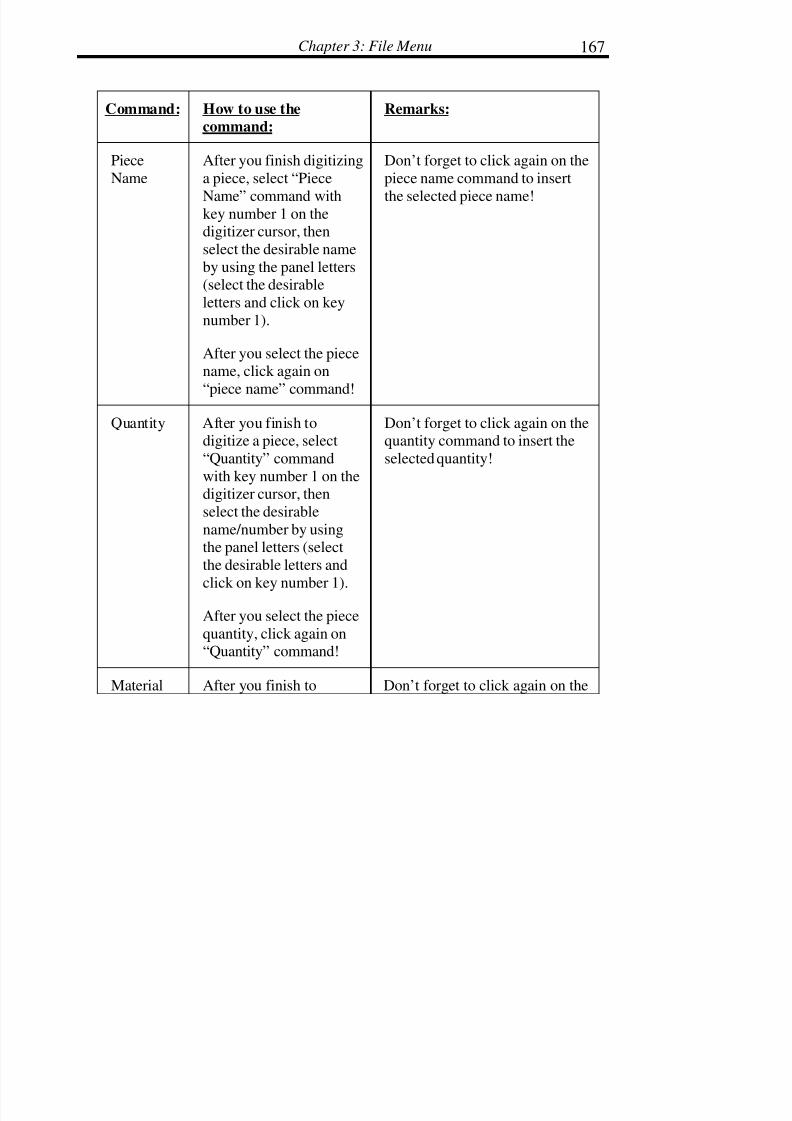
7/28/2019 OptiTex PDS User Manual
http://slidepdf.com/reader/full/optitex-pds-user-manual 191/727
Chapter 3: File Menu 167
Command: How to use the
command:
Remarks:
Piece
Name
After you finish digitizing
a piece, select “Piece
Name” command withkey number 1 on thedigitizer cursor, then
select the desirable name
by using the panel letters(select the desirable
letters and click on key
number 1).
After you select the piecename, click again on
“piece name” command!
Don’t forget to click again on the
piece name command to insert
the selected piece name!
Quantity After you finish todigitize a piece, select
“Quantity” command
with key number 1 on thedigitizer cursor, then
select the desirable
name/number by usingthe panel letters (select
the desirable letters and
click on key number 1).
After you select the piece
quantity, click again on“Quantity” command!
Don’t forget to click again on thequantity command to insert the
selected quantity!
Material After you finish to Don’t forget to click again on the

7/28/2019 OptiTex PDS User Manual
http://slidepdf.com/reader/full/optitex-pds-user-manual 192/727
Digitize, PDS & Grade Manual168
Type digitize a piece, select
“Material Type”
command with keynumber 1 on the digitizer
cursor, then select the
desirable name/numberby using the panel letters
(select the desirable
letters and click on keynumber 1). After you
select the piece material
type, click again on“Material Type”
command!
Material Type command to insert
the selected Material Type!
Piece
Description
After you finish to
digitize a piece, select
“piece description”
command with keynumber 1 on the digitizer
cursor, then select the
desirable name by usingthe panel letters (select
the desirable letters and
click on key number 1).
After you select the piecedescription, click again
on “piece description”command!
Don’t forget to click again on the
piece description command to
insert the selected piece
description!
Buffer After you finish to
digitize a piece, select
“Buffer” command with
Don’t forget to click again on the
buffer command to insert the

7/28/2019 OptiTex PDS User Manual
http://slidepdf.com/reader/full/optitex-pds-user-manual 193/727
Chapter 3: File Menu 169
key number 1 on the
digitizer cursor, then
select the desirable buffervalue by using the panel
letters (select the
desirable letters and click on key number 1).
After you select the piece
buffer, click again on
“buffer” command!
selected buffer!
Piece Code After you finish to
digitize a piece, select
“Piece Code” commandwith key number 1 on the
digitizer cursor, then
select the desirable piececode by using the panel
letters (select the
desirable letter and click on key number 1).
After you select the piece
code, click again on
“piece code” command!
Don’t forget to click again on the
piece code command to insert the
selected piece code!
Style
Name
After you finish to
digitize a piece, select“Style Name” commandwith key number 1 on the
digitizer cursor, then
select the desirable stylename by using the panel
Don’t forget to click again on the
style name command to insert theselected style name!

7/28/2019 OptiTex PDS User Manual
http://slidepdf.com/reader/full/optitex-pds-user-manual 194/727
Digitize, PDS & Grade Manual170
letters (select the
desirable letters and click
on key number 1).
After you select the stylename, click again on
“Style Name” command!
Rotate Any
Way
After you finish to
digitize a piece, select
“Rotate Any Way”command Click on
“Rotate Any Way”
command with key
number 1 on the digitizercursor if you want that,
the piece rotation will be
any way!
There is no need to click twice
on the rotate any way command!
Rotate
None
After you finish to
digitize a piece, select“Rotate None” command
Click on “Rotate None”
command with keynumber 1 on the digitizer
cursor if you want that,
the piece rotation will be
none!
There is no need to click twice
on the rotate none command!
Rotate 4
Way
After you finish to
digitize a piece, select“Rotate 4 Way”
command Click on
“Rotate 4 way” command
There is no need to click twice
on the rotate 4 way command!

7/28/2019 OptiTex PDS User Manual
http://slidepdf.com/reader/full/optitex-pds-user-manual 195/727
Chapter 3: File Menu 171
with key number 1 on the
digitizer cursor if you
want that, the piecerotation will be 4 way!
Rotate 2Way After you finish todigitize a piece, select
“Rotate 2 Way”
command Click on“Rotate 2 Way”
command with key
number 1 on the digitizercursor if you want that,
the piece rotation will be
2 way!
There is no need to click twiceon the rotate 2 way command!
Internal
Contour
Select the “Internal
Contour” command to
change to internal mode.
To change to internalmode click on the
“Internal Contour”
command with keynumber 1.
For exit from the internalmode click again!
Also F key on the digitizer cursor
is change to internal mode!
PieceOrient.
Right
Select the “Piece Orient.Right” command to
create to digitize piece
orientation to the right.
There is no need to click twiceon the Piece Orient. Right
command!

7/28/2019 OptiTex PDS User Manual
http://slidepdf.com/reader/full/optitex-pds-user-manual 196/727
Digitize, PDS & Grade Manual172
To create piece
orientation to the right,
click on the “PieceOrient. Right” command
with key number 1.
PieceOrient.
Left
Select the “Piece Orient.Left” command to create
to digitize piece
orientation to the left.
To create pieceorientation to the left,
click on the “Piece
Orient. Left” commandwith key number 1.
There is no need to click twiceon the Piece Orient. Left
command!
Piece
Orient.None
Select the “Piece Orient.
None” command to createto digitize piece
orientation to the None.
To create piece
orientation to the None,click on the “Piece
Orient. Left” command
with key number 1.
There is no need to click twice
on the Piece Orient. Nonecommand!
Use one Select the “Use one”
command if you want to
cancel “Use Both”orientation for the digitize
piece.
Use this command if you already
apply the “use both” command
and you want to cancel her.

7/28/2019 OptiTex PDS User Manual
http://slidepdf.com/reader/full/optitex-pds-user-manual 197/727
Chapter 3: File Menu 173
Use Both Select the “Use Both”
command to create to
digitize piece orientationof Both.
To create pieceorientation to the Both,
click on the “Use Both”
command with keynumber 1 on your
digitizer cursor.
There is no need to click twice
on the “Use Both” command!
Notch by 2
points
Select this command to
create notch with angle.
Click on the “Notch by 2
points” with key number1 on the digitizer cursorto select the command.
Then click twice, first
click on the segment (in
the desirable location)and the second click,
click on the piece to mark
the notch angle!
To go back to point position
(normal digitize position), click
on key number 0 on yourdigitizer cursor! Then you will be
able to continue digitize a newpiece.
T – Notch Select this command to
create T notch.
Click on the “T – Notch”
with key number 1 on the
If you have digitizer cursor with
4 buttons only, select the notch
command from the digitizermenu!

7/28/2019 OptiTex PDS User Manual
http://slidepdf.com/reader/full/optitex-pds-user-manual 198/727
Digitize, PDS & Grade Manual174
digitizer cursor to select
the command.
Then use key number 5
on your digitizer cursor toadd a notch in the
desirable location!
You can also create menu
position on your digitizer! This
way you will be able to selectnotch command on your digitizer
board.
V – Notch Select this command to
create V notch.
Click on the “V – Notch”
with key number 1 on the
digitizer cursor to selectthe command.
Then use key number 5
on your digitizer cursor toadd a notch in thedesirable location!
-“-
U – Notch Select this command to
create U notch.
Click on the “U – Notch”with key number 1 on the
digitizer cursor to select
the command.
Then use key number 5
on your digitizer cursor toadd a notch in the
desirable location!
-“-

7/28/2019 OptiTex PDS User Manual
http://slidepdf.com/reader/full/optitex-pds-user-manual 199/727
Chapter 3: File Menu 175
I - Notch Select this command
to create I notch.
Click on the “I – Notch”
with key number 1 on the
digitizer cursor to selectthe command.
Then use key number 5
on your digitizer cursor to
add a notch in thedesirable location!
-“-
L – Notch Select this commandto create L notch.
Click on the “L – Notch”with key number 1 on the
digitizer cursor to select
the command.
Then use key number 5on your digitizer cursor to
add a notch in the
desirable location!
-“-
Flip
Allowed
Select this command to
create “Flip Allowed” in
Piece Information”dialog.
Click on the “Flip
Allowed” command with
key number 1 on your
You don’t need to click twice on
Flip Allowed command!

7/28/2019 OptiTex PDS User Manual
http://slidepdf.com/reader/full/optitex-pds-user-manual 200/727
Digitize, PDS & Grade Manual176
digitizer cursor to select
this command.
Flip Non
Allowed
Select this command to
cancel “Flip Allowed”
command.
Click on “Flip NonAllowed” with fey
number 1 on your
digitizer cursor to cancelflip allowed.
“Undo” command (C key on the
cursor) in the digitizer dialog
doesn’t cancel commands, onlypoints (point keys number 1, 3, 0
and 9).
Mirror Select this command to
create a mirror to thedigitize piece.
Click on “Mirror”command with key
number 1 on yourdigitizer cursor to select
this command.
The mirror line will be
between the last point and
first point!
You will not see the mirror
command in the digitizer dialog!
Notch –
Prop
Select this command to
create attribute of proportional point in
notch dialog.
Click on the “Notch
Prop” command and then
When you select the notch prop
command, you are changing thenotch default!
This mean that all the nextnotches that you will add will
have “proportional” attribute!

7/28/2019 OptiTex PDS User Manual
http://slidepdf.com/reader/full/optitex-pds-user-manual 201/727
Chapter 3: File Menu 177
use key number 5 on your
digitizer cursor to add a
notch with the desirableattribute.
Notch –Prev Select this command tocreate attribute of
previous point in notch
dialog.
Click on the “NotchPrev” command and then
use key number 5 on your
digitizer cursor to add a
notch.
When you select the Notch Prevcommand, you are changing the
notch default!
This mean that all the next
notches that you will add willhave “previous” attribute!
Notch –
Next
Select this command to
create attribute of nextpoint in notch dialog.
Click on the “Notch
Next” command and then
use key number 5 on your
digitizer cursor to add anotch.
When you select the notch next
command, you are changing thenotch default!
This mean that all the next
notches that you will add will
have “next” attribute!
Cut Select this command tocreate cut attribute for
internal contour.
Click (before you start
digitize internal contour)on “Cut” command with
key number 1 on your
When you change the default of internal mode, it will be stay in
the last mode until you willchange the mode again.
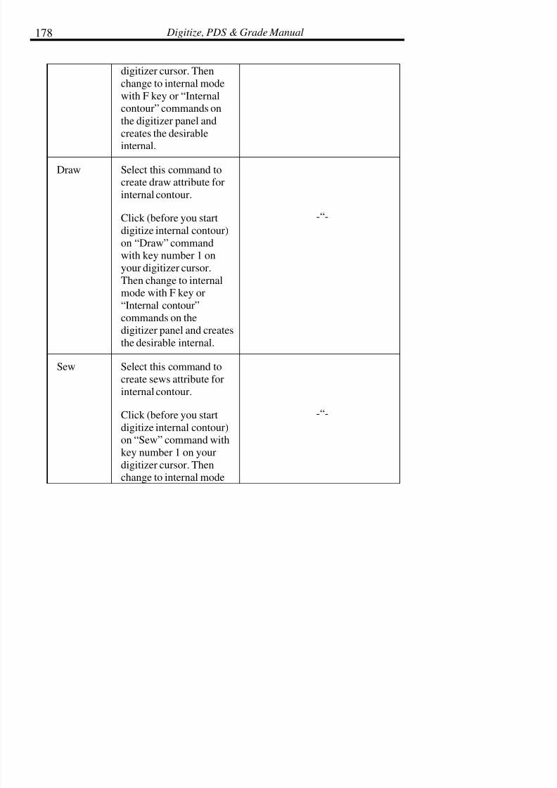
7/28/2019 OptiTex PDS User Manual
http://slidepdf.com/reader/full/optitex-pds-user-manual 202/727
Digitize, PDS & Grade Manual178
digitizer cursor. Then
change to internal mode
with F key or “Internalcontour” commands on
the digitizer panel and
creates the desirableinternal.
Draw Select this command tocreate draw attribute for
internal contour.
Click (before you start
digitize internal contour)
on “Draw” commandwith key number 1 on
your digitizer cursor.
Then change to internalmode with F key or
“Internal contour”
commands on thedigitizer panel and creates
the desirable internal.
-“-
Sew Select this command to
create sews attribute for
internal contour.
Click (before you startdigitize internal contour)on “Sew” command with
key number 1 on your
digitizer cursor. Thenchange to internal mode
-“-

7/28/2019 OptiTex PDS User Manual
http://slidepdf.com/reader/full/optitex-pds-user-manual 203/727
Chapter 3: File Menu 179
with F key or “Internal
contour” commands on
the digitizer panel andcreates the desirable
internal.
Quality Select this command to
create quality attribute for
internal contour.
Click (before you startdigitize internal contour)
on “Quality” command
with key number 1 on
your digitizer cursor.Then change to internal
mode with F key or
“Internal contour”commands on the
digitizer panel and creates
the desirable internal.
-“-
Apply
Rule
Select this command to
apply grading rule toselected point.
If you already selectgrading rule (see “Rule
Name” command), afteryou digitize a point, click on “Apply Rule”
command with key
number 1 on your
Don’t forget to load Grading
library before you start digitize!

7/28/2019 OptiTex PDS User Manual
http://slidepdf.com/reader/full/optitex-pds-user-manual 204/727
Digitize, PDS & Grade Manual180
digitizer cursor.
Rule name Select this commandwhen you want to apply
certain grading rule to
point!
After you finish todigitize a point (after you
create a point), click on
“Rule name” command,then select the rule name
from the panel letters and
click again on “Rule
name” command to saveto rule name.
1. Don’t forget to load Gradinglibrary before you start digitize!
2. Don’t forget to click again on
“Rule name” command after you
select the rule name.
3. After you select rule name, the
rule will automatically apply toselect point.
4. If you want to use the same
rule on different point, you can
select the new point and use“Apply Rule”.
Drill Select this commandwhen you went to create a
button with drill
command.
Click on “Drill”
(command before youcreate the button) with
key number 1 on your
digitizer cursor, then adda button in a desirable
location with key number
7 on your digitizer cursor(16 buttons cursor).

7/28/2019 OptiTex PDS User Manual
http://slidepdf.com/reader/full/optitex-pds-user-manual 205/727
Chapter 3: File Menu 181
Aux Drill Select this command
when you went to create a
button with Aux Drillcommand.
Click on “Aux Drill”(command before you
create the button) with
key number 1 on yourdigitizer cursor, then add
a button in a desirable
location with key number7 on your digitizer cursor
(16 buttons cursor).
Punch Select this command
when you went to create anotch with punch
command.
Click on “Punch”(command before you
create the button) with
key number 1 on yourdigitizer cursor, then add
a notch in a desirable
location with key number
5 on your digitizer cursor(16 buttons cursor).
NoneMode
Select this commandwhen you went to create a
notch or button with none

7/28/2019 OptiTex PDS User Manual
http://slidepdf.com/reader/full/optitex-pds-user-manual 206/727
Digitize, PDS & Grade Manual182
mode command.
Click on “None Mode”
(command before you
create the notch/button)with key number 1 on
your digitizer cursor, then
add a notch/button in adesirable location with
key number 5 on your
digitizer cursor (16buttons cursor).
Before Cut Select this command
when you went to create anotch, circle, button or
internal contour with
plotting/cutting time thatis before the external
contour.
Click on “Before Cut”
(command before youcreate the notch, button,
circle or internal contour)
with key number 1 on
your digitizer cursor, thenadd the desirable element
in the desirable locationwith the relevant keynumber on your digitizer
cursor (16 buttons
cursor).
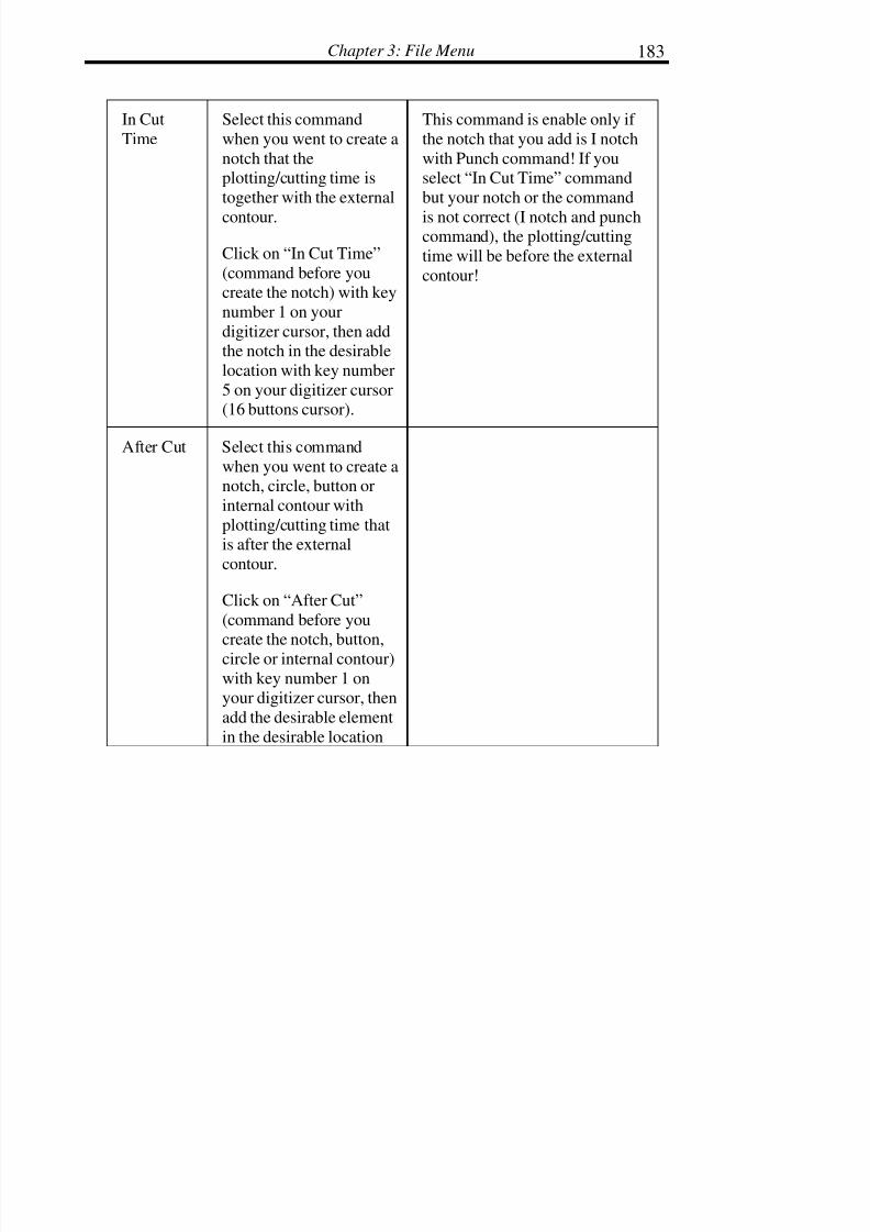
7/28/2019 OptiTex PDS User Manual
http://slidepdf.com/reader/full/optitex-pds-user-manual 207/727
Chapter 3: File Menu 183
In Cut
Time
Select this command
when you went to create a
notch that theplotting/cutting time is
together with the external
contour.
Click on “In Cut Time”
(command before youcreate the notch) with key
number 1 on your
digitizer cursor, then addthe notch in the desirable
location with key number
5 on your digitizer cursor(16 buttons cursor).
This command is enable only if
the notch that you add is I notch
with Punch command! If youselect “In Cut Time” command
but your notch or the command
is not correct (I notch and punchcommand), the plotting/cutting
time will be before the external
contour!
After Cut Select this command
when you went to create anotch, circle, button or
internal contour with
plotting/cutting time thatis after the external
contour.
Click on “After Cut”
(command before you
create the notch, button,circle or internal contour)
with key number 1 onyour digitizer cursor, then
add the desirable element
in the desirable location

7/28/2019 OptiTex PDS User Manual
http://slidepdf.com/reader/full/optitex-pds-user-manual 208/727
Digitize, PDS & Grade Manual184
with the relevant key
number on your digitizer
cursor (16 buttonscursor).
DefaultMode Select this commandwhen you want go back to
the default mode of all
internal elements.
Click on “Default Mode”command with key
number 1 on your
digitizer cursor.
You can set notch defaults inoption menu preferences dialog,
for all the other internal
elements, circle, button, dart andinternal contour the default will
be the last mode!
Default
Time
Select this command
when you want go back to
the default time of allinternal elements.
Click on “Default time”
command with key
number 1 on your
digitizer cursor.
You can set notch defaults in
option menu preferences dialog,
for all the other internalelements, circle, button, dart and
internal contour the default time
will be the last plotting/cuttingtime!
Max Tilt Select this command
when you want to create atilt angle to your digitize
piece.
Click on the “Max Tilt”
command with keynumber 1 on your
digitizer cursor, then
Don’t forget to click again on
max tilt command after youselect the tilt value.

7/28/2019 OptiTex PDS User Manual
http://slidepdf.com/reader/full/optitex-pds-user-manual 209/727
Chapter 3: File Menu 185
select the tilt angle value
with the panel number
and click again on “MaxTilt” command to save
and apply the tilt.
Flip non -
Allowed
After you finished
digitizing the piece, select
“Flip non – Allowed”command by clicking on
“Flip non – Allowed” cell
with key number 1 on thedigitizer cursor in order
give your digitized piece
“None” Flip Allowedattribute.
There is no need to click twice on
the “Flip non – Allowed” cell.
Flip X –
Allowed
After you finished
digitizing the piece, select
“Flip X – Allowed”command by clicking on
“Flip X – Allowed” cell
with key number 1 on thedigitizer cursor in order
give your digitized piece
“X Flip” Flip Allowedattribute.
There is no need to click twice on
the “Flip X – Allowed” cell.
Vice SideFlipped X
After you finisheddigitizing the piece, select“Vice Side Flipped X”
command by clicking on
“Vice Side Flipped X” cellwith key number 1 on the
There is no need to click twice onthe “Vice Side Flipped X” cell.

7/28/2019 OptiTex PDS User Manual
http://slidepdf.com/reader/full/optitex-pds-user-manual 210/727
Digitize, PDS & Grade Manual186
digitizer cursor in order
give your digitized piece
“Left/Right” OppositePiece attribute.
Vice Side
non Flipped
After you finished
digitizing the piece, select“Vice Side non Flipped”
command by clicking on
“Vice Side non Flipped”
cell with key number 1 onthe digitizer cursor in
order give your digitized
piece “None” OppositePiece attribute.
There is no need to click twice on
the “Vice Side non Flipped” cell.
Notch
Width
Select this command to set
your digitized notch width.
Click on “Notch Width”cell with key number 1 on
your digitizer cursor.
Now click on key number
5 on your digitizer cursor
to create notch on thedigitized piece.
NotchAngle
Select this command to setyour digitized notch width.
Click on “Notch Angle”cell with key number 1 on
your digitizer cursor.

7/28/2019 OptiTex PDS User Manual
http://slidepdf.com/reader/full/optitex-pds-user-manual 211/727
Chapter 3: File Menu 187
Now click on key number5 on your digitizer cursor
to create notch on the
digitized piece.
ButtonRadius
Select this command to setyour digitized button
radius.
1. Click on “ButtonRadius” cell with key
number 1 on your
digitizer cursor.
2. Select the button
radius from the
digitizer penal buyclicking on desirable
numbers cells.
3. Click again on
“Button Radius” cellcommand.
Now use key number 7 to
add a button to your
digitized piece.
DartDistance
Select this command to setyour digitized dart
distance.
1. Click on “Dart
Distance” cell with

7/28/2019 OptiTex PDS User Manual
http://slidepdf.com/reader/full/optitex-pds-user-manual 212/727

7/28/2019 OptiTex PDS User Manual
http://slidepdf.com/reader/full/optitex-pds-user-manual 213/727
Chapter 3: File Menu 189
1. Click on “AuxDrillmode” cell with key
number 1 on your
digitizer cursor.
Now use D key to add aDart to your digitized
piece.
Dart CutMode
Select this command tochange your dart drill
mode to “Cut mode”.
1. Click on “Cart Cut
Mode” cell with key
number 1 on your
digitizer cursor.
Now use D key to add a
Dart to your digitized
piece.
Dart Draw
Mode
Select this command to
change your dart drill
mode to “Draw mode”.
1. Click on “Dart Draw
Mode” cell with key
number 1 on yourdigitizer cursor.
Now use D key to add a
Dart to your digitized

7/28/2019 OptiTex PDS User Manual
http://slidepdf.com/reader/full/optitex-pds-user-manual 214/727
Digitize, PDS & Grade Manual190
piece.
Vice Side
Flipped Y
Select this command to set
your digitized pieceattribute to be “Left/Right”
attributed under Opposite
Piece filed in OptiTexpiece info dialog box.
1. Click on “Vic SideFlipped Y” cell with key
number 1 on your
digitizer cursor after youfinish digitized piece.
Flip Y
Allowed
Select this command to set
your digitized piece
attribute to be “Y Flip”attributed under Flip
Allowance filed inOptiTex piece info dialog
box.
1. Click on “Flip Y
Allowed” cell with key
number 1 on your digitizercursor after you finish
digitized piece.
Buffer TypeAround
Select this command to setyour digitized piece buffer
attribute to be “Around”
type under Buffer Typefiled in OptiTex piece info

7/28/2019 OptiTex PDS User Manual
http://slidepdf.com/reader/full/optitex-pds-user-manual 215/727
Chapter 3: File Menu 191
dialog box.
1. Click on “Buffer Type
Around” cell with key
number 1 on your digitizer
cursor after you finishdigitized piece.
Buffer Type
Up
Select this command to set
your digitized piece bufferattribute to be “Up” type
under Buffer Type filed in
OptiTex piece info dialogbox.
1. Click on “Buffer Type
Up” cell with key number
1 on your digitizer cursorafter you finish digitized
piece.
Buffer Type
Down
Select this command to set
your digitized piece bufferattribute to be “Down”
type under Buffer Type
filed in OptiTex piece infodialog box.
1. Click on “Buffer TypeDown” cell with key
number 1 on your digitizercursor after you finish
digitized piece.
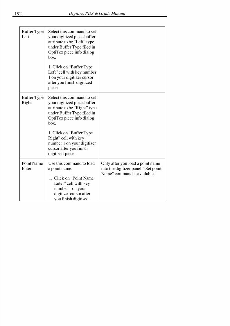
7/28/2019 OptiTex PDS User Manual
http://slidepdf.com/reader/full/optitex-pds-user-manual 216/727
Digitize, PDS & Grade Manual192
Buffer TypeLeft
Select this command to setyour digitized piece buffer
attribute to be “Left” type
under Buffer Type filed inOptiTex piece info dialog
box.
1. Click on “Buffer Type
Left” cell with key number
1 on your digitizer cursorafter you finish digitized
piece.
Buffer TypeRight
Select this command to setyour digitized piece buffer
attribute to be “Right” type
under Buffer Type filed inOptiTex piece info dialog
box.
1. Click on “Buffer Type
Right” cell with keynumber 1 on your digitizer
cursor after you finish
digitized piece.
Point Name
Enter
Use this command to load
a point name.
1. Click on “Point Name
Enter” cell with key
number 1 on yourdigitizer cursor after
you finish digitised
Only after you load a point name
into the digitizer panel, “Set point
Name” command is available.

7/28/2019 OptiTex PDS User Manual
http://slidepdf.com/reader/full/optitex-pds-user-manual 217/727
Chapter 3: File Menu 193
piece.
2. Now select the point
name by clicking on
the name letters cells
with digitizer cursor.
3. Click again on “PointName Enter” cell.
Set Point
Name
Use this command to
implement point name todigitised point.
1. After you finish
digitised a point, click
on “Set Point Name”
cell with the digitizercursor (key number 1).
This command is available only
after you load a point name with“Point Name Enter” command!

7/28/2019 OptiTex PDS User Manual
http://slidepdf.com/reader/full/optitex-pds-user-manual 218/727
Digitize, PDS & Grade Manual194
Digitizer Dialog Box:
Digitizer Type
This field lists the type of digitizer tablet being used.

7/28/2019 OptiTex PDS User Manual
http://slidepdf.com/reader/full/optitex-pds-user-manual 219/727
Chapter 3: File Menu 195
Panel
This field displays the panel currently being used. The panel taped to the
digitizer must be the same panel that is defined here. See above forinstructions on printing the Digitizer Panel.
Edit Panel
Click on this button to edit existing digitizer panels and to make new panels.See above for instructions on editing the digitizer panel.
Browse
Click on Browse to find and define the digitizer panel you wish to use.
Communication Port
Defines which communication port the digitizer is plugged into. Thecommunication port must also be set up for the defined digitizer type.
Working Units
Defines the working units.
Resolution
Defines the resolution.
16 Buttons Cursor
Enable 16 buttons cursor when using it. Disable 16 buttons cursor when using
a 4 buttons cursor.
Tablet Size
Width:

7/28/2019 OptiTex PDS User Manual
http://slidepdf.com/reader/full/optitex-pds-user-manual 220/727
Digitize, PDS & Grade Manual196
Defines the width of the digitizer tablet.
Height:
Defines the height of the digitizer tablet.
Shift Digitizer 0/0 point
Defines the 0/0 point on the digitizer.
Digitizer Communication Setup
Defines the specific communication parameters for your digitizer.
! Note: Digitizer installation Instructions of the supported devices can be
found in the output device installation chapter latter in this book.
7/28/2019 OptiTex PDS User Manual
http://slidepdf.com/reader/full/optitex-pds-user-manual 221/727
Chapter 3: File Menu 197
Export to CAD/CAM files
The Export CAD/CAM files command converts SGS files to any other graphic
formats listed in the dialog box.
Use the Layers table to define which items should be exported to which layer.The exported file is created using the working units defined in the Options
Menu.
To Export Files:
• From the File Menu select Export to CAD/CAM files... TheExport to CAD/CAM File dialog box is displayed.
! Note: Export individual sizes by selecting them with an “X” in the
Grading Table dialog box prior to choosing this command.
• Type in the name of the file to be exported.
• Click Browse to select the drive and directory where the file is tobe exported.
• Select the desired file format.
! Note: SGS software recognizes only the basic attributes of the different
ASCII geometry standards for each file format. Situations may arise
where the saved file does not appear exactly as it did in the original
application. The same limitation exists with the Import CAD/CAM
files command. If the file is not importable, use Import setup and change the parameters accordingly.
• OPTIONAL: Select any other options or set the scale size.
• Click OK.
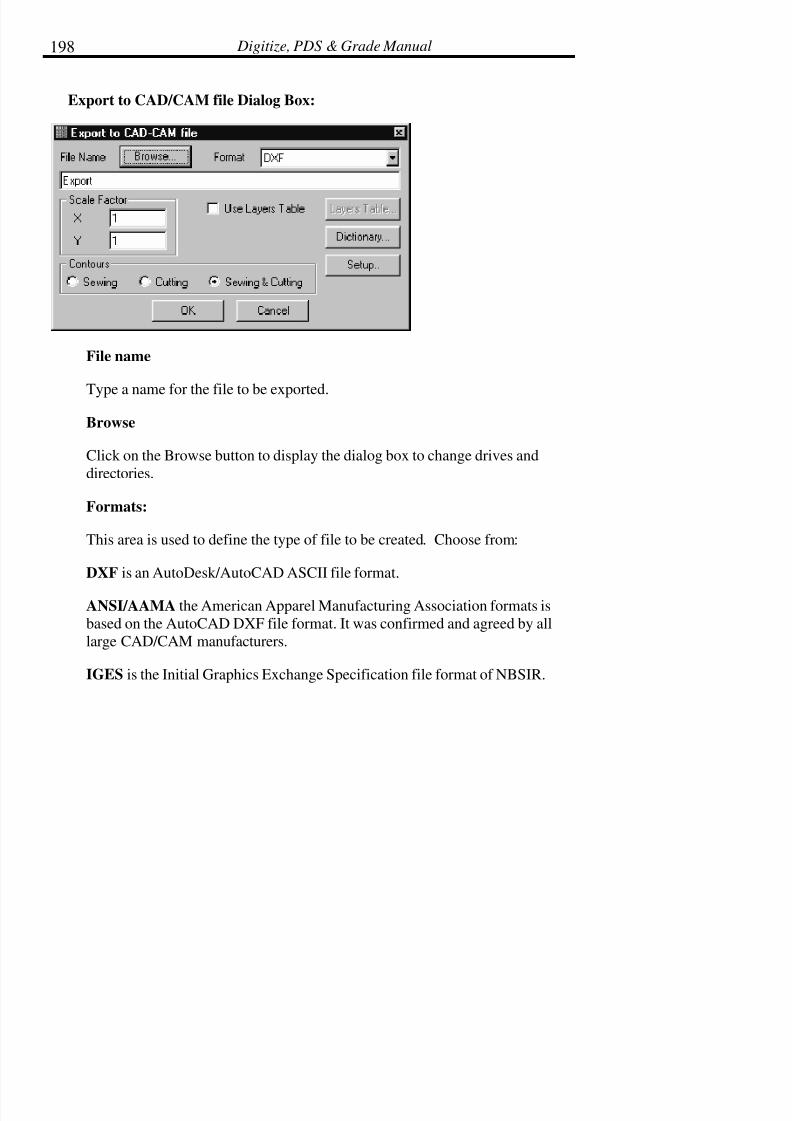
7/28/2019 OptiTex PDS User Manual
http://slidepdf.com/reader/full/optitex-pds-user-manual 222/727
Digitize, PDS & Grade Manual198
Export to CAD/CAM file Dialog Box:
File name
Type a name for the file to be exported.
Browse
Click on the Browse button to display the dialog box to change drives and
directories.
Formats:
This area is used to define the type of file to be created. Choose from:
DXF is an AutoDesk/AutoCAD ASCII file format.
ANSI/AAMA the American Apparel Manufacturing Association formats is
based on the AutoCAD DXF file format. It was confirmed and agreed by all
large CAD/CAM manufacturers.
IGES is the Initial Graphics Exchange Specification file format of NBSIR.
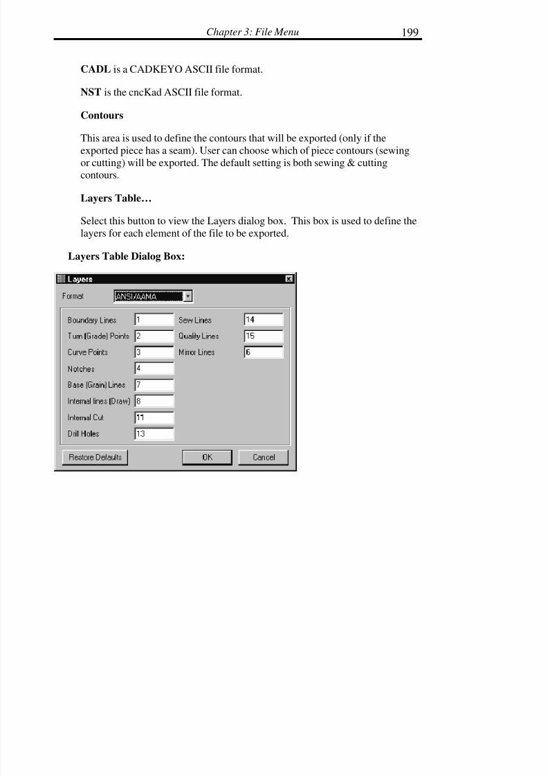
7/28/2019 OptiTex PDS User Manual
http://slidepdf.com/reader/full/optitex-pds-user-manual 223/727
Chapter 3: File Menu 199
CADL is a CADKEYO ASCII file format.
NST is the cncKad ASCII file format.
Contours
This area is used to define the contours that will be exported (only if theexported piece has a seam). User can choose which of piece contours (sewing
or cutting) will be exported. The default setting is both sewing & cuttingcontours.
Layers Table…
Select this button to view the Layers dialog box. This box is used to define the
layers for each element of the file to be exported.
Layers Table Dialog Box:

7/28/2019 OptiTex PDS User Manual
http://slidepdf.com/reader/full/optitex-pds-user-manual 224/727
Digitize, PDS & Grade Manual200
Dictionary Dialog Box:
Piece Name
Defines how the export file refers to the piece name.
Piece Code
Defines how the export file refers to the piece code.
Annotation
Defines how the export file refers to the annotation.
Size Name
Defines how the export file refers to the size name.

7/28/2019 OptiTex PDS User Manual
http://slidepdf.com/reader/full/optitex-pds-user-manual 225/727
Chapter 3: File Menu 201
Base Size Mark
Defines how the export file refers to the base size.
Material Code
Defines how the export file refers to a defined material group.
Quantity
Defines how the export file refers to the quantity.
Best Quality
Defines how the export file illustrates that the following defines the bestquality.
Orientation
Defines how the export file refers to the orientation.
Restore Defaults
Restores the default dictionary names for each item.
Import from CAD/CAM Files
The Import CAD/CAM command is an optional module of software that isactivated within SGS software packages when the Import Module is
purchased.
The Import Module converts any ASCII geometry file format from the list of
recognized formats to the SGS file format. The new file is loaded directly onto
the screen. Files from any directory or disk may be chosen as long as it is aformat recognized by the Import module.

7/28/2019 OptiTex PDS User Manual
http://slidepdf.com/reader/full/optitex-pds-user-manual 226/727
Digitize, PDS & Grade Manual202
! Note: AutoCAD files can be imported into SGS software regardless if
pieces were originally drawn clockwise or counter clockwise
To Set up the Import Options:
• From the File Menu choose Import CAD/CAM files... The ImportCAD/CAM files dialog box is displayed.
• Select the type of file to Import by checking the appropriate fileformat under the File Format field.
• Click Browse, and a second Import CAD/CAM File dialog box isdisplayed.
• Select the desired file(s) to import.
! Tip: To select multiple files, hold down the shift key and click on the
desired files.
• Click OK. The Import CAD/CAM Files dialog box is displayed
again.
• Select the desired Import options.
• Click on Setup. The Import Setup dialog box will be displayed.
• Select the options and enter the desired values.
•
Click OK. The Import CAD/CAM Files dialog box will bedisplayed again.
• Click OK. The selected files are imported with the desired valuesand options implemented.

7/28/2019 OptiTex PDS User Manual
http://slidepdf.com/reader/full/optitex-pds-user-manual 227/727
Chapter 3: File Menu 203
Import CAD files Dialog Box:
CAD Files to Import
This field will list the file to be imported. Click on the Browse button to select
the file or files to be imported.
Working Units
Select the desired working units: mm, cm, m, inches, feet, or yards. SGS
software uses the selected working units while converting files from one
format to another. If the units are not correctly defined, the pieces are importedas the wrong size and the command will have to be repeated.
7/28/2019 OptiTex PDS User Manual
http://slidepdf.com/reader/full/optitex-pds-user-manual 228/727
Digitize, PDS & Grade Manual204
File Format
Choose the type of file to be imported. Following are the different importable
file formats:
DXF - AutoDesk/AutoCAD ™ ASCII file format.
AAMA - The American Apparel Manufacturing Association format is based
on the AutoCAD DXF file format. It was confirmed and agreed by all largeCAD/CAM manufacturers.
IGES - Initial Graphics Exchange Specification file format of NBSIR.
CADL – CADKEY ™ ASCII file format.
Gerber - Gerber Cutter & Cutting Edge file format.
DFT - cncKad ASCII file format.
HP/GL - General output file format that can be sent to most HP-GL-compatible plotters. Approved by the American National Standard of the
Electronic Industrial Association.
MICROJET- File format used with the Microdynamics plotters.
DM-PL – Based on HP-GL format the use for IOLINE plotters.
No Sizes
When this option is disabled, all pieces with the same name become separatepieces. When this option in enabled, all pieces with the same name are made
into a graded nest.
! Note: For a graded nest to be created, the pieces name and size name must
be defined in the import file. The grade points are the break points

7/28/2019 OptiTex PDS User Manual
http://slidepdf.com/reader/full/optitex-pds-user-manual 229/727
Chapter 3: File Menu 205
(sharp corners). AAMA format files can be imported with grading,
but often the graded nest does not come through correctly. If the
Graded Nest does not come through see Graded Nest tool in the
Grading Menu section. This new SGS tool offers a solution to this
problem.
Make DSN files
If this command is enabled, a Style (DSN) File is created when importing aMarker File.
Material
This field notes the Material Group in Piece Info for the imported file(s).
Quantity
Defines the quantity in Piece Info for the imported file(s). If an import filecontains several of the same pieces, SGS software reads only one and willinsert the right number of copies into the Piece Info box. If there are
differences between the images, SGS software may not recognize that the
pieces are multiples of the same pattern piece.
Ignore Internals
Defines the specific components to be imported from the import file.
Eliminating specific components, like Notches, Texts, Lines, Arcs, or Circles,speeds the Import procedure. Selecting the Ignore Notch or Internals option
(Lines, Arcs, Circles, or Text), does not mean that these elements are not read.
In this case, these elements are read without being identified or sorted. Forexample, a V notch on the piece perimeter becomes part of the contour rather
than being recognized as a notch having a V attribute.
7/28/2019 OptiTex PDS User Manual
http://slidepdf.com/reader/full/optitex-pds-user-manual 230/727
Digitize, PDS & Grade Manual206
OK
Click on the OK button after selected the file to Import. The file will be
imported.
Box
Click on this button to import a file within a closed contour box. This option
is used to bring in information if the file will not be imported properly. Usehis option when an error dialog box appears such as “Entities Out of Contour”
or “No Closed Contours Found”.
Setup
Click on the Setup button to display the Import Setup Dialog Box.

7/28/2019 OptiTex PDS User Manual
http://slidepdf.com/reader/full/optitex-pds-user-manual 231/727
Chapter 3: File Menu 207
Import Setup Dialog Box:
Tolerance
The Tolerance Value determines the farthest distance between two points on a
contour can be placed apart and still be treated as the same perimeter (SGS
software usually handles only properly closed contours. However, thetolerance value ensures that some contours that are not closed properly will be
read).
7/28/2019 OptiTex PDS User Manual
http://slidepdf.com/reader/full/optitex-pds-user-manual 232/727
Digitize, PDS & Grade Manual208
Bulge (Chord Error)
Bulge (Chord Error) is a parameter used to define the smoothness of Curves
and Arcs. A smaller value creates many additional points and segments withinthe piece.
Min. Area
Min Area section uses to define the smallest piece that will be recognized inOptiTex import program as a piece.
Any element that is smallest from the value in the “Min. Area window” will be
recognizes as internal element!
! Note: In OptiTex Import Program, internal elements that are not located
in a piece (external contour that is close), will be not import!
Piece
If a piece boundary is smaller than the value defined in this box, the Import
command disregards the piece and throws the piece away.
Hole
A hole is a closed contour on the same layer as the piece boundary. Use this
area to define the minimum size of a hole. The minimum area of a hole shouldbe smaller than the smallest piece.
Default Internals Sizes:
These fields define the default settings for internals when importing fromanother file format.

7/28/2019 OptiTex PDS User Manual
http://slidepdf.com/reader/full/optitex-pds-user-manual 233/727
Chapter 3: File Menu 209
Button Radius
This field is used to set the default size for the radius of a button.
Notch Depth
This field is used to set the default depth of a notch.
Notch Width
This field is used to set the default for the width of a notch.
Text Size
This field is used to set the default for text size. If a text size was defined inthe Imported file, SGS software maintains that value.
Text is information typed directly onto the piece. Piece Description text is
defined using the Dictionary dialog box.
V Notch’s Recognizing parameters
Max. Internal angle
This field is used to define V notch size in order to help the import system to
recognize V notch when the import format is DXF.
! Note: In AAMA import format there are special layers that define V notch.
7/28/2019 OptiTex PDS User Manual
http://slidepdf.com/reader/full/optitex-pds-user-manual 234/727
Digitize, PDS & Grade Manual210
Max. Relative angle
This area is used to define the maximum angle of a V notch.
Near Angle
This area is used to define the smallest near angle of a V notch.
Min Circle Radius
This field defines the smallest size of an internal circle that will be imported.
Max Notch Ratio
The largest difference when dividing the width by the depth of the notch.
Max Notch Depth
The field is used to define the maximum depth for a notch.
Spline Angle
The smallest angle for curved lines.
Max Grade Angle
The maximum angle for a graded nest.
Ignore CR / LF
Mainly for CNC files which come in one long line, or use a CR/LF after eachpoint. When enabled, the Carriage Return/Line Feed in the import file is
ignored.

7/28/2019 OptiTex PDS User Manual
http://slidepdf.com/reader/full/optitex-pds-user-manual 235/727
Chapter 3: File Menu 211
Ignore Frame
SGS software ignores the outer frame (boundary) which is usually created for
Plot files.
Separate Layers
SGS software remembers the layer of each element. If the new file is ever
exported, the elements keep their original layers.
This option is used only for DXF and AAMA files. Because SGS softwarerecognizes elements and text on different layers, a circle inside a shape may
make a noticeable difference in the imported file. If the circle is imported
while the Separate Layers option is disabled, the circle becomes a simpleinternal element. If the circle is to be recognized as a hole, it must be on the
same layer as the outer perimeter line, or the DXF file can be imported with
the Separate Layers option in the OFF position.
Units
This area displays the Working Unit Values that are defined in the Options
Menu. If working units are set up incorrectly, the file is imported as the wrongsize and will need to be imported again.
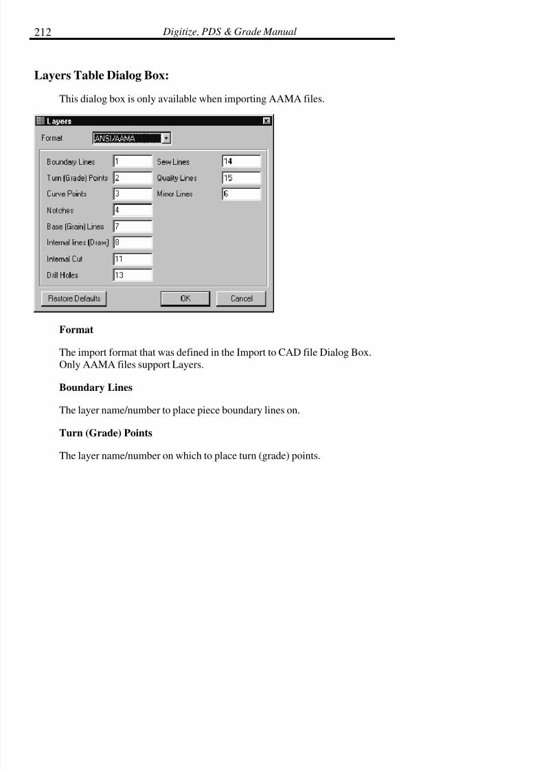
7/28/2019 OptiTex PDS User Manual
http://slidepdf.com/reader/full/optitex-pds-user-manual 236/727
Digitize, PDS & Grade Manual212
Layers Table Dialog Box:
This dialog box is only available when importing AAMA files.
Format
The import format that was defined in the Import to CAD file Dialog Box.
Only AAMA files support Layers.
Boundary Lines
The layer name/number to place piece boundary lines on.
Turn (Grade) Points
The layer name/number on which to place turn (grade) points.
7/28/2019 OptiTex PDS User Manual
http://slidepdf.com/reader/full/optitex-pds-user-manual 237/727
Chapter 3: File Menu 213
Curve Points
The layer name/number on which to place curve points.
Notches
The layer name/number on which to place notches.
Grain (Base) Lines
The layer name/number that define the grain (base) line.
Internal Lines (draw)
The layer name/number on which to place internal lines. If internal lines areused and they are to be cut with an Automatic cutter, they should appear on the
same layer as the outer perimeter. Otherwise, they will become internal
elements with Draw attributes.
Internal Cut
The layer name/number on which to place internal cuts. If internal lines are
used and they are to be cut with an Automatic cutter, they should appear on thesame layer as the outer perimeter. Otherwise, they will become internal
elements with Draw attributes.
Drill Holes
The layer name/number that define the drill holes.
Sew Lines
The layer name/number on which to place sew lines.
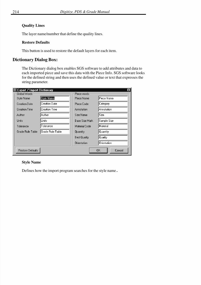
7/28/2019 OptiTex PDS User Manual
http://slidepdf.com/reader/full/optitex-pds-user-manual 238/727
Digitize, PDS & Grade Manual214
Quality Lines
The layer name/number that define the quality lines.
Restore Defaults
This button is used to restore the default layers for each item.
Dictionary Dialog Box:
The Dictionary dialog box enables SGS software to add attributes and data to
each imported piece and save this data with the Piece Info. SGS software looks
for the defined string and then uses the defined value or text that expresses thestring parameter.
Style Name
Defines how the import program searches for the style name.

7/28/2019 OptiTex PDS User Manual
http://slidepdf.com/reader/full/optitex-pds-user-manual 239/727
Chapter 3: File Menu 215
Piece Name
Defines how the import program searches for the piece name. If a piece name
string is not defined; the longest line of text in the import file becomes thePiece Name.
Piece Code
Defines how the import program searches for the piece code.
Annotation
Defines how the import program searches for annotation.
Size Name
Defines how the import program searches for the size name.
Base Size Mark
Defines how the import program searches for the base size.
Material Code
Defines how the import program searches for the fined material group.
Quantity
Defines how the import program searches for the defined quantity.
Best Quality
Defines how the import program searches for the defined best quality.

7/28/2019 OptiTex PDS User Manual
http://slidepdf.com/reader/full/optitex-pds-user-manual 240/727
Digitize, PDS & Grade Manual216
Orientation
Defines how the import program searches for the defined orientation.
Restore Defaults
This button is used to restore the default dictionary names for each item.

7/28/2019 OptiTex PDS User Manual
http://slidepdf.com/reader/full/optitex-pds-user-manual 241/727
Chapter 3: File Menu 217
SGS Modulate
About SGS Modulate
Modulate is a "Made to measure" program which is intended for production of
single or mass numbers of garments, each fitting specific sets of dimensions.These dimensions can belong to specific people or can represent specific
manufacturing requirements presented as a scheme of dimensions.
Modulate produces "Parametric Garments". A "Parametric garment" is a set of
patterns that construct a garment. Modulate adds to these patterns sets of
dimensions specified by the "Parametric Garment" designer , giving them anynames and relations required.
Once the "Parametric Garment" has been fully defined by a set of dimensions,
it can be used over and over for any number of dimension sets. Dimension sets
are all the dimensions required to fully define a "Parametric Garment". Forexample a parametric shirt may be defined using dimensions named "Back
Waist" , "ArmoHole" , "Chest" & "Side" . Given these four dimensions
Modulate will reshape the garment to fit these dimensions.
A difficult problem in creating parametric patterns has been the unexpected
behavior of the parametric model. This means that after assigning differentdimension sets to a parametric model it produced wrong point movements
which resulted in a wrong garment.
To avoid this Modulate has taken a unique approach. During the process of
defining the Parametric model the user can visually simulate its operation. For
example after adding a "Leg Length" dimension the user can simply drag thisdimension causing the entire garment to recalculate accordingly and view its
effect. If the model performs incorrectly the dimension can be assigned
differently by adding or removing other constraints and then rechecked untilthe parametric model perform correctly.

7/28/2019 OptiTex PDS User Manual
http://slidepdf.com/reader/full/optitex-pds-user-manual 242/727
Digitize, PDS & Grade Manual218
Export to SGS Modulate
This command will export the style file to custom fit file, in order to edit it in
the Modulate software.
Modulate File Name
Browse to locate the place to store the custom fit file.
Select Size
Select the desire size to be saved.
Import from SGS Modulate
Modulate maintains a database of Parametric Patterns.
This command display the Modulate Server window, from which you canselect one or more patterns that have been assigned specific dimension values.
To Import CUS file:
• Browse the database to locate the desire Modulate file.
• Change the dimension value if necessary.
• From the FILE menu select LOAD FILE.

7/28/2019 OptiTex PDS User Manual
http://slidepdf.com/reader/full/optitex-pds-user-manual 243/727
Chapter 3: File Menu 219
Plot
About Plotting
Use the Plot command to Plot or Cut the displayed pieces. Files can be plotted
at a plotting device connected directly to one of the serial ports on yourmachine, or plots can be plotted to a plotting device connected to a network.

7/28/2019 OptiTex PDS User Manual
http://slidepdf.com/reader/full/optitex-pds-user-manual 244/727
Digitize, PDS & Grade Manual220
The new Output Control Center (OCC) is a utility which manages plot files as
well as queues on local and networks computers.
Use the print manager of your choice. The OutMan (Output Manager) is aWindows utility supplied by SGS software, which manages files. Files can be
sent to up to eight different serial printers or plotters. The QMan works in co-
ordination with the OutMan and acts as a spooler for the different plot files.
The OutMan also works in a network situation. From different workstations,network files can be sent to different devices and OutMan plots them without
interfering with the regular workflow of SGS Applications.
If the OutMan is selected, enable the use of OutMan’s application in the Plot
dialog box. Also, refer to the Configuring SGS Software to Your Plotter
section in the Installation and setup chapter of the manual.
There is a difference between the Plot and Print commands. Plot is used when
using the OutMan print spooler to support your large pen plotters (Gerbers andIolines) and InkJet/Dot Matrix plotters (HP600, EnCad, AlgoTex, and the
CalComp InkJet). A4/Letter paper size is referred to as small, and all paper
sizes larger than this are referred to as large.
Print is used when using the Windows print spooler and windows to supportyour small InkJet/Laser/Dot Matrix printer (such as HP, Canon etc.).

7/28/2019 OptiTex PDS User Manual
http://slidepdf.com/reader/full/optitex-pds-user-manual 245/727
Chapter 3: File Menu 221
! Note: If you use only one plotter, you will not have to select and configure
a plotter each time. The configuration will be saved in the
OUTMAN.INI. If you have more than 1 plotter, once they are
configured you will only have to specify the PLTR#.
Plotter Installation
! Note: Make sure that your plotter is installed and turned on.
! Note: To access the Plot command, there must a piece in the working area.
Plotter (Output Manager) Setup
In order to use the plot command to send a job to an existing plotter, SGS
software must be configured properly. The Plotter Setup command defines the
communication parameters for the plotters in use. Up to 8 different plotters
can be defined in a network.
! Note: Select between the OutMan and the OCC as the output manager in
the Plot dialog box. The "Use Output Manger" must be checked.
! Note: The communication parameters in the computer output port should
have been previously set to match the same parameters in the output
device. A print manager for a Local or Network Plotter should have
also been installed. For more information, refer to the Configuring
SGS software To Your Plotter section in the end of this book.
Setting the OutMan as Output Manager
• From the Plot dialog box select the OutMan as output manager.
• From the File Menu choose Plotter (Output Manager) Setup. ThePlotter Setup Dialog box is displayed
• Enable the Output Manager by clicking the box. A small V is

7/28/2019 OptiTex PDS User Manual
http://slidepdf.com/reader/full/optitex-pds-user-manual 246/727
Digitize, PDS & Grade Manual222
placed in the box.
! Note: In most cases the Output Manager must be enabled in order to plot.
• Next, specify where the settings you select are to be saved; to dothis you will need to locate your Output Manager INI file. Click
Browse to view your directories. The Output Manager INI Filedialog box will be displayed.
• Select the OptiTex directory. (The file Outman.ini automaticallydisplays in the File Name field.)
• Click OK. The Plotter Setup dialog box is displayed with theselected Outman.ini path shown.
! Note: The SGS PDS, Grading, and Marking software all use the same
OutMan and Plotter Setup dialog boxes. Some options only apply to
PDS and are not accessible in the Marking software, and vise-versa.
• Select the plotter by clicking the drop down arrow to the right of the current plotter and select the appropriate PLTR#.
! Note: The number of plotters in the list depends on how many plotters
were specified during the Marking program Installation procedure.
• Click OK.
To Output Using the OutMan Print Manager:
• From the File menu choose Open. The Open dialog box willdisplay.
• Select the desired Design file.

7/28/2019 OptiTex PDS User Manual
http://slidepdf.com/reader/full/optitex-pds-user-manual 247/727
Chapter 3: File Menu 223
! Tip: To open a file quickly, double click the file name.
• Click OK to open the file. Select a piece.
• From the File menu select Plot. The Plot dialog box is displayed.Verify that the correct file is displayed in the file name box. If
not, click Browse and select the correct file.
• Select the desired options.
! Tip: Verify that the correct Set up, paper size and plotter width, have been
selected prior to clicking OK.
• Click OK to save changes and exits the Plot Setting Dialog Box.The pieces will be plotted or cut.
! Tip: Once a file has been sent to the OutMan, you can continue to work at
your computer.

7/28/2019 OptiTex PDS User Manual
http://slidepdf.com/reader/full/optitex-pds-user-manual 248/727
Digitize, PDS & Grade Manual224
SGS software uses the WYSIWYG (what you see is what you get) system
while printing and plotting. This means that what you see (on the screen) iswhat you get from the output device.
Setting the Output Control Center (OCC) as Output Manager
The Output Control Center (OCC) is used to communicate with your ploter orcutter as well as manage all your plotting jobs.
The OCC supports plotter in local computer or on any other computer on your
network.

7/28/2019 OptiTex PDS User Manual
http://slidepdf.com/reader/full/optitex-pds-user-manual 249/727
Chapter 3: File Menu 225
To setup plotter to work with the OCC Manger
Use this command to install a new plotter on your computer, to connect to a
network plotter installed on another computer, or change the configuration of
an existing plotter.
• Click the ADD button to add a plotter.
• Select between "My Computer" and "Network Computer"depends where the plotter is connected.
Plotter connected to network computer
You can type the name of the remote
Computer (computer with the plotter) and click Connect, or double click on
Entire Network to browse and find your computer. Once you find your
computer, click on the + sign to see the plotters shared on this computer.
Select the desired plotter, then Finish.
You can now ready to plot to a remote plotter across your network.
Adding Plotter on Local Computer
Select the Port (COME, LP, etc) your plotter is connected to, then Next.
give the plotter queue a name For each plotter a Queue is created to hold,
process and store files for your plotter. The default location will be displayedin the Plotters Queue Folder. To change the Queue location, click on the
Browse button then select the desired location for the Queue.
Check the Shared Plotter box to make this plotter is available to other
computers.
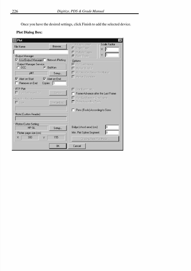
7/28/2019 OptiTex PDS User Manual
http://slidepdf.com/reader/full/optitex-pds-user-manual 250/727
Digitize, PDS & Grade Manual226
Once you have the desired settings, click Finish to add the selected device.
Plot Dialog Box:

7/28/2019 OptiTex PDS User Manual
http://slidepdf.com/reader/full/optitex-pds-user-manual 251/727
Chapter 3: File Menu 227
File Name
The File Name field contains the destination and name of the plot or cut file
that you are creating. To select a different file name or directory click onBrowse.
Use Output Manager
This option must be enabled to use the OutMan. The OutMan allowsautomatic plotter, if the OutMan is not enabled, the plot file is created and
stored in the displayed directory. Then, the plot file has to be copied to the
appropriate port.
Network Plotting
Enable this command when plotting through the network.
Output Manager Service
Choose between the OCC (Output Control Center) or the OutMan.
Alert on Start
When this option is enabled, a message will alert the user that the job is about
to start plotting. This message is displayed on the screen of the computer
attached to the plotter. Click OK to proceed.
Alert on End
When this option is enabled, a message will alert the user that the job hasfinished plotting. This message is displayed on the screen of the computerattached to the plotter. Click OK to proceed.

7/28/2019 OptiTex PDS User Manual
http://slidepdf.com/reader/full/optitex-pds-user-manual 252/727
Digitize, PDS & Grade Manual228
Remove on End
When this option is enabled, the plot file is deleted after it is plotted.
Copies
This option allows specification of he number of copies to be plotted.
Plot to Ftp
This option enables you to upload the plot file to ftp server.
How To Use The FTP Plot Utility Feature:
There are three basic things that OptiTex user should have in Order to use thenew FTP plot utility feature:
• IP address (Internet protocol) of the destination computer.
• Password in case that the destination computer is passwordprotected.
• User Name in case other users share the destination computer.
Now, you can contact your computer using standard network cable to the
destination computer network.
After you connect to your network follow the following steps:
• Go to “Plot Dialog” box.
• Use “Setup” button in “FTP Plot” section in order to open ftp
dialog box:
• Insert the destination Computer IP addresses to “Address”
7/28/2019 OptiTex PDS User Manual
http://slidepdf.com/reader/full/optitex-pds-user-manual 253/727
Chapter 3: File Menu 229
windows and if there is a need, insert User name and Password .
• Now press on “Browse” button to access your destinationcomputer network (the access process can take some time).
• From the “Select Working directory” windows select the workingdirectory which will be a target directory for the plot will.? On the“Path” windows the selected directory path will be displayed (you
can’t edit the path on the “Path” windows).
• Confirm your selection with Ok button.
• On the Plot dialog check “Use FTP plot” option.
• Send the plot file to this destination using “Ok” on plot dialog box.
Log File Reports - Use
This option writes plot information to a log file that contains information about
the marker, number of pieces placed and material usage. The log file can thenbe used for tracking plotted files. To view the log file, use a text editor or
select Solutions Reports from the Nesting Menu.
Change Log
Click on Change Log to change the text file to which the plot information is
written.
Note (Custom Header)
This option allows the user to type in notes or instructions and plot them at the
end of the marker in the header. Note that if Marker Header is disabled, the
notes do not plot.

7/28/2019 OptiTex PDS User Manual
http://slidepdf.com/reader/full/optitex-pds-user-manual 254/727
Digitize, PDS & Grade Manual230
Plotter/Cutter Setting
This option displays the plotter type in use and how it is configured. It also
displays the plotter page size. Plotters and plotter settings can be changed inthe Plotter Setting dialog box. To open the Plotter Settings dialog box click on
Setup.
Plot Setting Dialog Box:
The Plot Setting dialog box can be accessed through the Plot dialog box.

7/28/2019 OptiTex PDS User Manual
http://slidepdf.com/reader/full/optitex-pds-user-manual 255/727
Chapter 3: File Menu 231
Device Name
Name is the assigned name of the plotter. Up to 8 plotters can be defined.
They are listed as PLTR1, PLTR2, etc. The name can be changed in the Plotter
Setup command.
Driver Format
This option displays the Language the plotter is using. Consult yourplotter/cutter manual for language information for specific information related
to your plotter or cutter. Plotter Size. Each output device, whether it is a plotter
or a cutter, is treated as a plotter. Each kind of an X Y machine has its own
type of command file or language. The following plotter types are supported:
DM-PL (*.DMP)
HP-GL (*.HPG)
HP-GL PlotTec (*.HPT)
HP-GL Generic(*.HPG)
HP-GL /2 (*.HP2)
Design Partner (*.DP)
IOLS (*.IOL)
EIA (*.EIA)
Cybrid Plotter
Cybrid Cutter/Plotter
Mutoh Plotter

7/28/2019 OptiTex PDS User Manual
http://slidepdf.com/reader/full/optitex-pds-user-manual 256/727
Digitize, PDS & Grade Manual232
APGL Gerber Plotter (*.GGT)
AP700 Plotter
Gerber Cutter (*.GBR)
Eastman Cutter (*CMD)
Cutting Edge Cutter (*NC)
Wild Plotter/Cutter
Wild Plotter (*.WIL)
Microjet (*STD)
External Format
Device Options:
0,0 Page in Center
This option keeps jobs aligned when using more than one page. Most plotters
have their 0/0 point located at the Bottom Left point of the paper, althoughsome may have their 0/0 point set at the center of the page. If using a plotter,
which has a 0/0 point at the center, enable this option. This orientation setting
is used primarily for flat bed plotters.
Manual Frame Advance
This option is used primarily on flat bed plotters and plotters that do not feed
paper automatically. The plot stops at the end of each page to allow for paperreplacement. If this option is enabled, the Enter key must be pressed after each
page.

7/28/2019 OptiTex PDS User Manual
http://slidepdf.com/reader/full/optitex-pds-user-manual 257/727
Chapter 3: File Menu 233
Use CR/LF in Code
Certain Gerber Cut Formats only use this option. Some Gerber cutters require
a new line after each command and some do not. The best way to check if your cutter needs to have a new line is to look at one of its example files. If the
file is one long paragraph, this command is not necessary. If the file starts each
command on a new line, this option must be enabled.
Use Initialization in File Header [<M70>/<IN>/…]
Some Gerber Cut Formats use this option. When enabled, it instructs the cutter
to stop and wait for the user permission to continue/start the job. Not allGerber plotters support this command. Consult the Gerber User’s Manual for
information on plotter/cutter support.
Use Bite Offset
This option is only supported by the Gerber Cut format. When enabled, itinstructs the plotter to put a small alignment mark on the fabric at the end of
each frame. The small mark is placed outside the Marker area so as notinterfere with the actual marker.
Use Plotter’s Built in Fonts
When this option is enabled, the plotter substitutes the fonts used on the
computer with its own built in fonts. Not all plotters have built in fonts.
Consult the plotter’s manual for font information. Using the plotters built in
fonts speeds up plotting.
Plotter Font File
Click Browse to select a font file. The Open Font File dialog box displaysallowing a font to be selected from a specific drive or directory. If Use Plotters
Built in Fonts is disabled, you must use the PLOT-ENG.FNT file.

7/28/2019 OptiTex PDS User Manual
http://slidepdf.com/reader/full/optitex-pds-user-manual 258/727
Digitize, PDS & Grade Manual234
Default Font Size (Inches)
This is the font size, which the plotter automatically uses if no other size is
specified. The default is .315
Plotter Page Size
Determines the working area of the plotter. The program will “remember” the
last setting even if it was for a different plotter. X is the length of the frame orthe endless length of the paper roll. Y is the width of the paper.
Gap after Plotting
This is the space the plotter puts at the end of the plot job. The default is 0.
Minimal Plot/Cut line
This option is only used for some Gerber plotters. It specifies the minimumdistance at which a line is still being cut. It saves plotting/cutting time to not
cut two points that are too close to one another.
Tools Setup Tab
The new tools setup feature enables OptiTex users to plot different line type
according to tool number or tool type.
There are several different plotter formats, which are support different lines
type:
HG-PL, DM-PL, HG-PL/2, Wild Plotter, AP 700 Plotter, Muto Plotter etc'
In order to plot a different line type follow the next steps:

7/28/2019 OptiTex PDS User Manual
http://slidepdf.com/reader/full/optitex-pds-user-manual 259/727
Chapter 3: File Menu 235
• How defined a special tool to a selected element:
• For defining a special tool number to a selected piece use "ToolNumber/Layer Name" section on "Piece Info" dialog or "Cut
Order" dialog on Piece menu.
• For defining a special tool number to an internal element use"Tool Number/Layer Name" section on internal element attributedialog. Select the desirable internal and use double click function
to open the attribute dialog box (you select the internal and then
open the internal attribute dialog box from "Edit" menu). You canalso add a special tool number for internal on "Cut Order" dialog
box.
! Tip: You can use OptiTex new feature to select a tool name, just click with
mouse right button on "Tool Number/Layer Name" section and a
dialog box will be open:
• Now, after you defended new special tools for a selected elementinternal or external, the news tool name will be display on the"Tools" column with the rest of OptiTex standard tools. Now,
defined a line type on "Plot setup" dialog box:

7/28/2019 OptiTex PDS User Manual
http://slidepdf.com/reader/full/optitex-pds-user-manual 260/727
Digitize, PDS & Grade Manual236
• Insert the tool number in to the "Head Number" column on thecorrect rows according the desirable tool or command type.Remember you can give only numeric names on "Head Number"
column!
• Select the desirable line type from the list. Don't forget to fill inthe tool number into the "Number of Heads" windows!
• Confirm your selection with "OK" button.

7/28/2019 OptiTex PDS User Manual
http://slidepdf.com/reader/full/optitex-pds-user-manual 261/727
Chapter 3: File Menu 237
To change line type:
• Find the tool that you want to change his line type z
• Click on the field, a drop down menu appears.
• Select the desire line type from the menu.
How to work with "Tool setup" tab on "Plot setup" dialog box:
The new tools setup feature enables OptiTex users to plot different line types
according to tool numbers or tool types.
There are several different plotter formats, which are support different linestype:
HG-PL, DM-PL, HG-PL/2, Wild Plotter, AP 700 Plotter, Muto Plotter, etc.'
In order to plot a different line type follow these next steps:
How to define a special tool to for a selected element:
• To define a special tool number for a selected piece use "ToolNumber/Layer Name" section on "Piece Info" dialog or "CutOrder" dialog on Piece menu.
• To define a special tool number for an internal element use "ToolNumber/Layer Name" section on internal element attribute dialog
box.. Select the desired internal element and use the double click
function to open the attribute dialog box (you select the internaland then open the internal attribute dialog box from "Edit" menu).
You can also add a special tool number for internal on "Cut
Order" dialog box.
! Tip :You can use the new OptiTex feature to select a tool name:, just click with

7/28/2019 OptiTex PDS User Manual
http://slidepdf.com/reader/full/optitex-pds-user-manual 262/727
Digitize, PDS & Grade Manual238
right mouse button on "Tool Number/Layer Name" section and a dialog box will open:
• Now, after you define new special tools for a selected element,internal or external, the news tool name will be displayed on the
"Tools" column with the rest of OptiTex standard tools. To definea line type on "Plot setup" dialog box:

7/28/2019 OptiTex PDS User Manual
http://slidepdf.com/reader/full/optitex-pds-user-manual 263/727
Chapter 3: File Menu 239
• Insert the tool number in the "Head Number" column on thecorresponding rows according the desired tool or command type.Remember you can only use numeric names in the"Head
Number" column!
• Select the desired line type from the list. Don't forget to fill in thetool number into the "Number of Heads" windows
7/28/2019 OptiTex PDS User Manual
http://slidepdf.com/reader/full/optitex-pds-user-manual 264/727
Digitize, PDS & Grade Manual240
Page Format:
Single
This option scales the marker to fit on one page. The page size is specified in
the Plot Settings dialog box (see below).
Multiple
Select this option when plotting to a smaller plotter that limits the width of the
marker. This option will plot the marker so that the marker width (Y) is scaled
to fit on the plotter paper. The marker length (X) is then scaled to match thescaling of the width.
Fixed Scale
Allows the user to specify scale (i.e. 4 to 1.) The default scale is 1 to 1, full
scale.
! Note: If the output device is smaller than the marker, SGS software creates
a file, which is already divided into the required number of pages.
Each page is marked at a specific location with joining marks to
help overlap (tile) the pages to complete the whole picture.

7/28/2019 OptiTex PDS User Manual
http://slidepdf.com/reader/full/optitex-pds-user-manual 265/727
Chapter 3: File Menu 241
Options
Plot Continuous
Select this option to plot continuously. Plotters with roll paper generally plot
continuously. Plotters with manual page feed do not plot continuously.
! Note: If the actual marker is wider than the plotter, the selected option is
Scale equal to 1 X 1 and Continuous Plot is enabled, then special
marks are plotted to join two or more sections of the plot.
Marker Header
When this option is enabled, general maker information such as size, plies, and
number of pieces placed, notes, etc. is plotted at the end of the marker.
Plot Header Above the Marker
When this option is enabled, the header of the Marker will plot above it.
Marker Boundary
When this option is enabled, the marker boundary or frame is plotted aroundthe marker edge.
One Frame Only
This option scales the selection to fit on one plotter page and works in
conjunction with Plot Continuous.
Frame Advance after the Last Frame
This option when using a pen plotter that plots in defined frames. For example,
the Ioline 600 plots in 46” frames. It is necessary to check this option so that
the plotter will advance after plotting the first frame.

7/28/2019 OptiTex PDS User Manual
http://slidepdf.com/reader/full/optitex-pds-user-manual 266/727
Digitize, PDS & Grade Manual242
Plot/Cut Piece in One Frame
This option is using with flat bead plotters/cutters. When this option is
enabled any piece that is not within the frame in whole will not be plotted orcut.
Order According Tools
This option is used when more than one pen or knife is used to cut or draw themarker. When enabled, all sections assigned to one tool can be sent at the
same time: all the notches are cut or plotted first, then drills, then punches, and
then the cut sequence. This allows for a changing of tools between sections.
Pens (Tools) According to Sizes
When using a multiple pen plotter, it is possible to assign each size a different
pen. Select this option to enable plotting with pens according to size.
Bulge (Chord Error) Inches
The Bulge (Chord Error) setting is the smallest size at which an arc can appearand still be plotted as an arc. When plotting arcs with very small bulge chords
(practically straight lines) it is faster to plot them as straight lines. This saves
plotting time. If the Bulge (Chord Error) is set to 0, the curve is plotted, nomatter how slight.
Min. Plot Spline Segment
The minimum plot spline segment setting is the setting that determines the
smallest spline or arc to be cut as a spline or arc. This setting is not importantfor setup but may be adjusted later to improve the speed or quality of plots.

7/28/2019 OptiTex PDS User Manual
http://slidepdf.com/reader/full/optitex-pds-user-manual 267/727
Chapter 3: File Menu 243
Plotting Options for Graded Pieces
In PDS select Grading Options to choose how graded piece will plot. This
option is used to select which sizes will and will not plot and if a graded nestwill plot as a nest or if each size will grade as a separate piece.
Separate Grading Options dialog box:
Plot each size separately
Select this option to plot each size as a separate piece, rather than a gradednest.
Sizes
Select the sizes to be plotted by enabling or checking the box beside the size
name. If the box next to the size name is not checked, that size will not beplotted.

7/28/2019 OptiTex PDS User Manual
http://slidepdf.com/reader/full/optitex-pds-user-manual 268/727
Digitize, PDS & Grade Manual244
Plotter Setup
! Note: the plotter setup dialog box is different between the OutMan and the
OCC.
Plotter Setup Dialog (OutMan manager)
Use Output Manager
Select this option to use the Output Manager provided by SGS. When this
option is disabled, the plot file is created but is not sent to the output device.
Output Manager INI File:
The default INI file is C:\OPTITEX\OUTMAN.INI. If a different INI file is
desired, select Browse to display the Output Manager INI-File dialog box andselect the appropriate file.
Current Plotter
Select the plotter to be used in the Current Plotter drop down box. Up to 8different plotters can be configured in a server setting.

7/28/2019 OptiTex PDS User Manual
http://slidepdf.com/reader/full/optitex-pds-user-manual 269/727
Chapter 3: File Menu 245
Plotter Setup Dialog (OCC)
• Select the plotter to be used in the plot command.
• The plotter can be set as default by clicking the SET DEFAULTbutton
• Click "Close"

7/28/2019 OptiTex PDS User Manual
http://slidepdf.com/reader/full/optitex-pds-user-manual 270/727
Digitize, PDS & Grade Manual246
Use the Print command to output pieces to a printer. The Printer drivers are
part of Microsoft Windows, so SGS software displays the printer driver(s) thatwas (were) selected when Microsoft Windows was installed.
The Print command uses Windows printer drivers and spoolers; therefore, the
output device must be installed through the Windows Setup before printing
takes place.
Print is used when using the Windows print spooler to support small
InkJet/Laser/Dot Matrix printer (such as HP, Canon etc.). A4/Letter paper sizeis referred to as small, and all paper sizes larger than this are referred to as
large. Text sent to printer can be different from the text seen on screen. Use
the Fonts Command in the Options Menu to change the font type and size
To Print a File:
• From the File Menu select Print or click the Print icon on the toolbar. The Print dialog box is displayed.
• Select the desired printing options.
• Click OK.

7/28/2019 OptiTex PDS User Manual
http://slidepdf.com/reader/full/optitex-pds-user-manual 271/727
Chapter 3: File Menu 247
Print Dialog Box:
Actual Size
Select Actual Size to print the contents of the file in full scale regardless of the
paper size. This may require multiple pieces of paper.
Fit to Page
Select Fit to Page to print the contents of the file on one page. The defaultsetting for printing is Fit to Page.
Scale
Scale allows the contents of the file to be printed in a specified scale. For
example, a scale of 1 is 100%, and .50 is 50%.
Width
Width allows the user to specify a width for the print out. When a width is
specified, notice that the scale changes accordingly.

7/28/2019 OptiTex PDS User Manual
http://slidepdf.com/reader/full/optitex-pds-user-manual 272/727
Digitize, PDS & Grade Manual248
Height
Height allows the user to specify a height for the print out. When a height is
specified, notice that the scale changes accordingly.
Print selected piece only
When this option is selected only the selected piece prints when this option is
checked.
Print to file
This option generates a separate print file when checked.
Setup
Setup defines format for printer. Refer to the Printer Setup section for more
information.
Printer Setup
Select Printer Setup to display the Print Setup dialog box. This dialog boxshows the default printer where SGS files are sent as well as displaying
printing options.
To Set up Your Printer:
• From the File Menu choose Printer Setup to display the PrinterSetup dialog box.
• Select the desired printing options (paper, orientation, and size).
• Click OK.
7/28/2019 OptiTex PDS User Manual
http://slidepdf.com/reader/full/optitex-pds-user-manual 273/727
Chapter 3: File Menu 249
! Note: Make sure to select printing parameters carefully. Some printer
drivers may not support different text sizes and fonts. Consult the
printer manual for exact specifications.
Default Printer:
The Default Printer will be displayed. The Default printer is configuredthrough the Windows Control Panel. To select a different printer, click the
drop down arrow to the right of the Specific Printer and select the desiredprinter.
Orientation and Paper Size:
The orientation determines whether the file will print in portrait or landscape.Clicking the drop down arrow to the right of Paper Size can change the paper
size.
Report to Excel and E-Mail utilities
Generates a report in Excel’s native format from OptiTex PDS and
E-Mails the report and the file directly from OptiTex PDS.
The style file can be converted to excel file and can be mailed and reported by
using this dialog box.
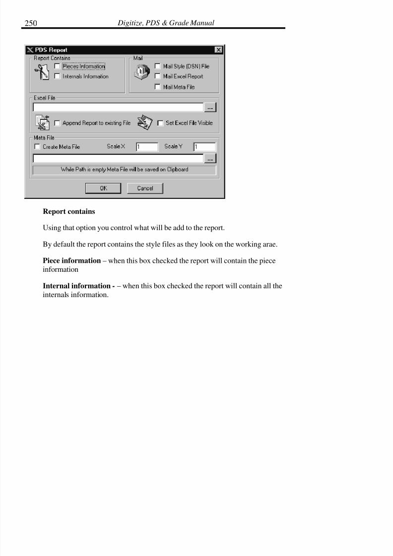
7/28/2019 OptiTex PDS User Manual
http://slidepdf.com/reader/full/optitex-pds-user-manual 274/727
Digitize, PDS & Grade Manual250
Report contains
Using that option you control what will be add to the report.
By default the report contains the style files as they look on the working arae.
Piece information – when this box checked the report will contain the pieceinformation
Internal information - – when this box checked the report will contain all the
internals information.

7/28/2019 OptiTex PDS User Manual
http://slidepdf.com/reader/full/optitex-pds-user-manual 275/727
Chapter 3: File Menu 251
Excel File
By clicking on the “…“ button you can browse the files on yours hard drive
and define the name of the excel file to be created.
You can set excel file visible and the after saving the file it will be opened
automatically.
Other option is to appended report to existing file and then the report will beadded at the end of the Excel file that has been chosen at the upper field.
MetaFile
To create a MetaFile you must check the box .
The scale X and scale Y fields gave the option to increases or decrees the sizeof the MetaFile.
"…" – by clicking this button you can browse your drive to locate the place
that the file will be saved
OptiTex can mail the style files to any mail recipient. You can attendee to the
massage 3 different files.
DSN file – mail the style file as he saved by optitex .
Excel report – mail the excel file.
MetaFile – mail a picture witch can insert to any office document or can be
opened with acrobat reader.
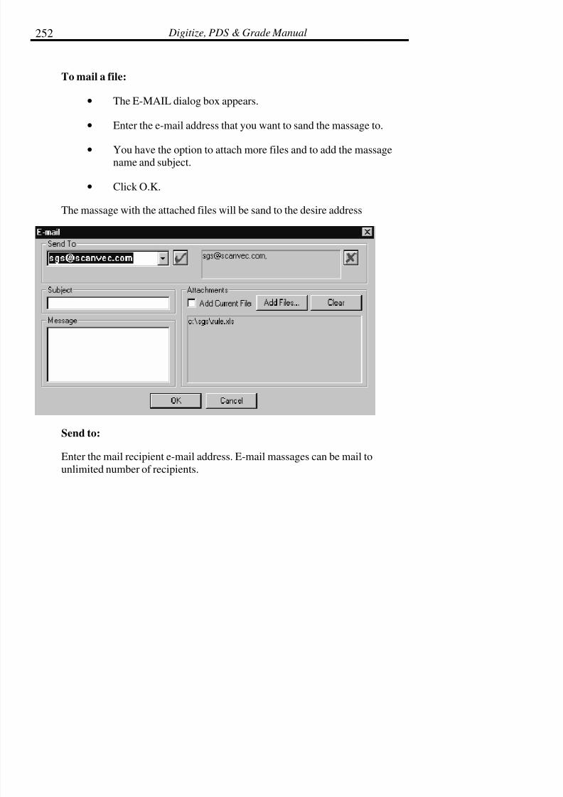
7/28/2019 OptiTex PDS User Manual
http://slidepdf.com/reader/full/optitex-pds-user-manual 276/727
Digitize, PDS & Grade Manual252
To mail a file:
• The E-MAIL dialog box appears.
• Enter the e-mail address that you want to sand the massage to.
• You have the option to attach more files and to add the massagename and subject.
• Click O.K.
The massage with the attached files will be sand to the desire address
Send to:
Enter the mail recipient e-mail address. E-mail massages can be mail to
unlimited number of recipients.

7/28/2019 OptiTex PDS User Manual
http://slidepdf.com/reader/full/optitex-pds-user-manual 277/727
Chapter 3: File Menu 253
Attachments:
To add files to the e-mail massage check the “Add current file” box and the
“Add Files” button to locate the files to sand.
Exit (Alt+F4)
Select the Exit command to close the Style File and exit the program.
To Exit the Program:
From the File menu chooses Exit or press ALT+F4.

7/28/2019 OptiTex PDS User Manual
http://slidepdf.com/reader/full/optitex-pds-user-manual 278/727
Chapter 4: Edit Menu 255
Chapter 4: Edit Menu
The Edit Menu contains commands for editing selected pieces. To select oneof the Edit menu commands, highlight the command in the menu and press the
left mouse button, or use the shortcut keys which are listed in parentheses next
to the command in the pull down menu. Using the corresponding tool icondisplayed on the tool bar also accesses edit commands.
! Tip: Display toolbars by choosing Toolbar from the Display menu and
then selecting the appropriate toolbar to display (covered in the
Tools chapter).
Undo (Ctrl+Z)
Use the Undo command to reverse the most recent action performed in the
Style File. The Undo command may be chosen to undo the 20 most recent
operations, back to adding a piece to the working area. Undo does not work toundo the loading of the file.
! Tip: Press the Control key and the Z key to undo.
Redo (Ctrl+Y)
Use the Redo command to reverse any operation changed by the Undo
command. Continue to choose the Redo command until all of the “undone”
operations have been reversed.
! Tip: Press the Control key and the Y key to redo.
Cut Current Piece (Ctrl+X)
Use the Cut Piece command to remove the selected piece from the open Style() file and copy it to the clipboard. Then use the Paste Piece command to paste
the copied pattern piece into the same DSN file, a different DSN file, or

7/28/2019 OptiTex PDS User Manual
http://slidepdf.com/reader/full/optitex-pds-user-manual 279/727
Digitize, PDS & Grade Manual256
marker file. The cut selection can continue to be pasted until something else is
placed onto the clipboard.
! Note: Cut Piece functions the same as the Copy Piece except Cut Piece
removes the original piece and Copy Piece leaves the original piece.
! Note: When cutting and pasting pattern pieces from one DSN file to
another, the pasted pieces acquire the sizes defined in the current
file, even when the base size and size names are different.
! Tip: Press the Control key and the X key to cut.
To Cut a Pattern Piece:
• Select the piece to cut.
• From the Edit Menu select Cut Piece, click on the Cut to
Clipboard icon, or use Ctrl + X.
• Open the file where the object is to be pasted.
• From the Edit Menu select Paste Piece. The selected object isplaced into the file and displayed in the working area.
Copy Pieces
This command has four options:
• Copy Current Piece (CTRL + C)
• Copy Working Area
• Copy Highlighted Pieces
• Copy All Pieces
7/28/2019 OptiTex PDS User Manual
http://slidepdf.com/reader/full/optitex-pds-user-manual 280/727
Chapter 4: Edit Menu 257
Use the Copy Piece command to copy selected pattern pieces to the clipboard.
Then use the Paste Piece command to paste the copied pattern piece(s) into thesame DSN file, a different DSN file, Modulate document or marker file. The
copied selection can continue to be pasted until something else is placed onto
the clipboard.
! Note: When cutting and pasting pattern pieces from one DSN file to
another, the pasted pieces acquire the sizes defined in the current
file, even when the base size and size names are different
! Tip: Press the Control key and the C key to copy.
To Copy a Pattern Piece(s):
• Select the piece(s) to copy.
• From the Edit Menu select Copy Piece, click on the Copy to
Clipboard icon, or use Ctrl + C.
• Open the file where the object is to be pasted.
• From the Edit Menu select Paste Piece. The selected object isplaced into the file and displayed in the working area.
Paste Piece (Ctrl+V)
Use the Paste command to paste the last pattern cut or copied onto theclipboard into the current DSN file or into a different DSN file. The cut/copied
selection can continue to be pasted until something else is placed onto theclipboard.
! Note: When cutting and pasting pattern pieces from one DSN file to
another, the pasted pieces acquire the sizes defined in the current file,
even when the base size and size names are different

7/28/2019 OptiTex PDS User Manual
http://slidepdf.com/reader/full/optitex-pds-user-manual 281/727
Digitize, PDS & Grade Manual258
! Tip: Press the Control key and the V key to paste.
To Paste a Pattern Piece into a DSN file:
• Cut or copy the selected piece by choosing the appropriatecommand from the Edit menu.
• Open the file where the object is to be pasted.
• From the Edit Menu select Paste Piece. The selected object isplaced into the file and displayed in the working area.
Copy/Paste Internals
Use Copy/Paste Internals command to copy internal elements from one piece
to another as well as within one piece.
• Select Internals to be copied using the Rectangle Tool in theEdit Tools Toolbar.
• From the Edit Menu select Copy / Paste Internals > CopyInternals.
• Select the piece to paste internals and from the Edit Menu selectCopy / Paste Internals >Paste Internals
Clear Selected Pieces
Removes only selected pieces from the working area.
• Select the pieces to be removed from the working area. Afterthe first piece is selected, highlight the others using the Shift +Left Mouse Click.

7/28/2019 OptiTex PDS User Manual
http://slidepdf.com/reader/full/optitex-pds-user-manual 282/727
Chapter 4: Edit Menu 259
• From the Edit Menu select Clear Selected Pieces
• Replace Old – replaces the pieces in the piece bar with thecurrent pieces in the working area
• Remove Current - removes pieces in the working area withoutupdating the original pieces in the piece bar.
• Make New – removes pieces from the working area andsimultaneously creates duplicates of pieces that were previously
in the working area.
Clear Selected Piece
Use Clear Selected Pieces to remove all pattern pieces from the working areaat one time. When using Clear Pieces, three different options are available,
Replace Old, Remove Current, and Make New.
Replace Old:
Replace Old replaces the pieces in the piece bar with the current pieces on the
screen. Use this option to clear the working area while updating the originalpieces with the newly edited pieces.
To Clear Pieces and Replace Old:
• Select Clear Pieces from the Edit Menu.
•Select Replace Old and all pieces on the working area of thescreen replace existing pieces in the Piece Bar.

7/28/2019 OptiTex PDS User Manual
http://slidepdf.com/reader/full/optitex-pds-user-manual 283/727
Digitize, PDS & Grade Manual260
Remove Current
Remove Current removes pieces in the working area without updating theoriginal pieces. Use this option to clear the working area of all pieces without
keeping any edits.
To Remove Current Pieces from the Working Area:
• Select Clear Pieces from the Edit Menu.
• Choose Remove Current and all pieces on the working area of the screen are removed while the original pieces in the Piece Barremain.
Make New
Make New removes pieces from the working area and simultaneously creates
duplicates of pieces that were previously in the working area. Use this optionto clear the working area and create duplicates of each piece.
! Tip: To bring back pieces that have been cleared, use the Undo command
from the Edit menu.
To Clear the Screen and Make New Pieces:
• Select Clear Pieces from the Edit Menu.
• Select Make New to return all pieces on the working area of the
screen to the piece bar, and to make duplicates of each piece.Duplicates also appear in the Piece Bar.

7/28/2019 OptiTex PDS User Manual
http://slidepdf.com/reader/full/optitex-pds-user-manual 284/727
Chapter 4: Edit Menu 261
Move Base Line
The Move command moves a selected object according to values entered in
the dialog box. The Move command in the Edit Menu switches between, MoveBaseline, Move Point, Move Notch, and Move Internal Element depending on
what object is selected on the selected piece. For example, if a point isselected, the Move commands changes to, “Move Point.” If an internalelement (drill hole, internal line, text, etc.) is selected, the Move command
changes to “Move Internal.” If a notch is selected, the Move command
changes to, “Move Notch.” If nothing is selected or a base line is selected, theMove command changes to, “Move Base Line.”
When selecting the Move command, more than one internal element, notch, orpoint may be selected. To select more than one point, click and drag the cursor
clockwise along the piece contour or press the Shift key to add additional
points. To select more than one internal element, press and hold the Shift key
and click on the desired elements. To select multiple notches not directly nextto one another, press and hold the Shift key and click on the individual
notches.
! Note: The following Example illustrates how to move a Point using the
Move command in the Edit Menu.
To Move a Point:
• Select the point.
• From the Edit Menu select Move Point. The Move Point dialogbox is displayed.

7/28/2019 OptiTex PDS User Manual
http://slidepdf.com/reader/full/optitex-pds-user-manual 285/727
Digitize, PDS & Grade Manual262
! Note: If the Move Point option is not visible, check to see that a point is
selected on the piece. Only when a point(s) is selected, is the Move
Point option available.
• Enter the desired distance or X and Y values to move the point.
• OPTIONAL: Enable Move Along Contour to move the point adistance along the original contour. When Move Along Contour
is selected, 2 choices are available: absolute and proportional.
These options are detailed in the section below.
• Click OK.
Move Point Dialog Box:
The X increment and Y increment fields correspond to movement along the X
and Y axis. To move the point 1” to the right and 2” up, enter 1 in the Delta Xbox and 2 in the Delta Y box. Use negative numbers to move points down and
to the left. Measurements may be defined for both X and Y values.
The Distance and Angle refer to the total movement of the point or notch.
Notice that when values are entered into one of the Delta X or Y boxes, the

7/28/2019 OptiTex PDS User Manual
http://slidepdf.com/reader/full/optitex-pds-user-manual 286/727
Chapter 4: Edit Menu 263
distance displayed is changed to reflect the value that was entered. When a
value is entered in both the Delta X and Y boxes, the total distance and anglesthe point moves is calculated and displayed automatically. If the angle and the
distance to move a point are known, those values may also be entered into
correspond boxes and the Delta X and Delta Y boxes are automatically
calculated.
Enabling the Move along Contour box allows movement of the point a specific
distances from the previous or next point along the original contour. The next
point is always determined in a clockwise direction. The previous point isalways determined in a counter clockwise direction. When this option is
selected, two methods of determining the distance to move the point are
available, absolute and proportional.
Absolute refers to the actual distance from the previous or next point.
Proportional refers to the percent amount from the previous or next point.
Either method may be used to move a point along a contour.
Delete Piece (Del)
Use the Delete command to delete a piece, internal element, point, or notch.
Delete in the Edit menu switches between, Delete Piece, Delete Point, Delete
Notch, and Delete Internal Element depending on what object is selected onthe working screen. For example, if a point is selected, the Delete commands
changes to, “Delete Point.” If an internal element (drill hole, internal line, etc.)
is selected, the Delete command changes to “Delete Internal.” If nothing is
selected or a base line is selected, the Delete commands changes to, “DeletePiece.”
When choosing the Delete command, more than one internal element, notch,
or point may be selected. To select more than one point, click and drag thecursor clockwise along the piece contour or press the Shift key to add

7/28/2019 OptiTex PDS User Manual
http://slidepdf.com/reader/full/optitex-pds-user-manual 287/727
Digitize, PDS & Grade Manual264
additional points. To select more than one internal element, press and hold the
shift key and click on the desired elements. To select multiple notches notdirectly next to one another, press and hold the shift key and click on the
individual notches.
! Note: The following example illustrates how to delete a point using the
Delete command in the Edit menu.
To Delete a Point:
• Select the point.
! Tip: To select more than one point, click and drag the cursor in a
clockwise direction or press and hold the Shift key to select
individual points.
• From the Edit Menu select Delete Point or press the Delete key to
delete all selected elements.

7/28/2019 OptiTex PDS User Manual
http://slidepdf.com/reader/full/optitex-pds-user-manual 288/727
Chapter 4: Edit Menu 265
Attributes (Enter)
Use the Attributes command to display and/or change the attributes of a
selected element of a piece. The Attributes command in the Edit Menuswitches between, Point Attributes, Inner Elements Attributes, and Notch
Attributes depending on what element is selected on the working area. Forexample, if a point is selected, the Attributes command changes to, “PointAttributes.” If an internal element (drill hole, internal line, etc.) is selected, the
Attributes command changes to “Inner Elements Attributes.” If nothing is
selected or a base line is selected, the Attributes command is grayed out.
! Tip: Another way to access attributes of an object is to select the object
and press the Enter key.
! Note: The following example illustrates how to change the attributes of a
point using the Point Attributes command in the Edit menu.
To Display/Change Point Attributes:
• Select the point.
• From the Edit Menu select Point Attributes, or press Enter. ThePoint Attributes dialog box is displayed.
• Verify or change the desired options.
• Click Apply to accept the changed values, or click Close to
close the dialog box without changing any of the selected
attributes.
The following dialog boxes change according to the object that is selectedprior to choosing the attributes command. If an internal element is selected,one of the following boxes displays Line Attributes, Text Attributes, Button
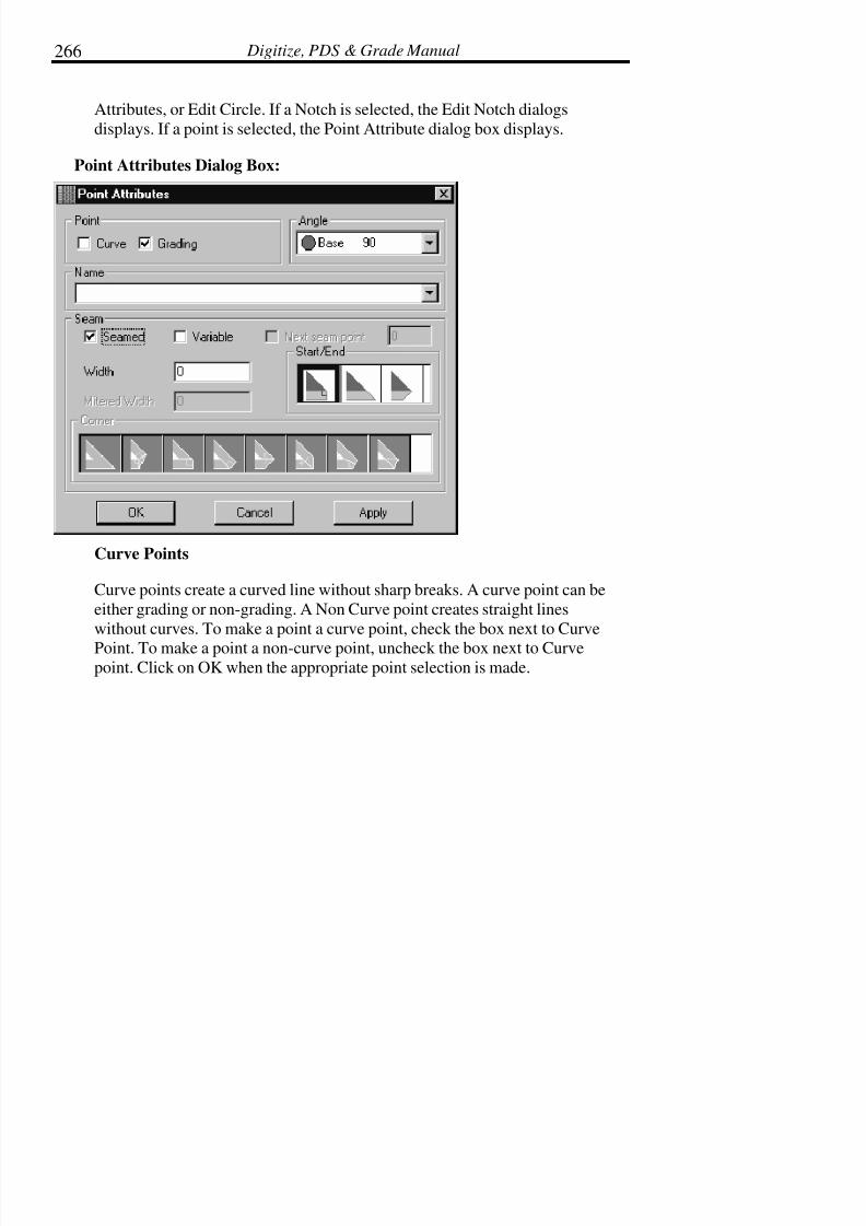
7/28/2019 OptiTex PDS User Manual
http://slidepdf.com/reader/full/optitex-pds-user-manual 289/727
Digitize, PDS & Grade Manual266
Attributes, or Edit Circle. If a Notch is selected, the Edit Notch dialogs
displays. If a point is selected, the Point Attribute dialog box displays.
Point Attributes Dialog Box:
Curve Points
Curve points create a curved line without sharp breaks. A curve point can be
either grading or non-grading. A Non Curve point creates straight lines
without curves. To make a point a curve point, check the box next to Curve
Point. To make a point a non-curve point, uncheck the box next to Curvepoint. Click on OK when the appropriate point selection is made.
7/28/2019 OptiTex PDS User Manual
http://slidepdf.com/reader/full/optitex-pds-user-manual 290/727
Chapter 4: Edit Menu 267
Grading Points
Grading points are used to establish a specific point where grading is applied
on a piece (mostly used for apparel). A grading point is represented by a small
black square on the piece perimeter or line segment. A Grading point may be
on a straight line or a curved line. To make a point a grading point, check thebox next to Grade Point.
Non grading points are represented by a small black circle, Non grading points
are used to help shape the piece boundary. A non-grading point will blend withthe previous and next grading points, and is therefore sometimes called a
blending grade. Non grading points may not be assigned values in the grade
table. To make a point a non-grading point, uncheck the box next to Gradepoint. Click on OK when the appropriate point selection is made.
Angle
The point angle is displayed in the Point Attribute dialog.
Name
The point can be named for reference with the Bubble Info (see View menu)
and with Grading (see Grading menu “Apply Rule with Name”).
Seam
The Seam field indicates if seam allowance has been applied to a point. Thefield also shows the amount of seam allowance applied as well as the corner
type if the point is on a corner. The main purpose of this box is simply forverification. To change seam allowance values, see the Seam section in the
Piece chapter, or see the Seam Allowance tool in the Tools chapter.

7/28/2019 OptiTex PDS User Manual
http://slidepdf.com/reader/full/optitex-pds-user-manual 291/727
Digitize, PDS & Grade Manual268
Add Relative
Use the Add Relative command to add a Point or Notch or button (drill)
relative to a selected point. This command is used for adding points, notches,and buttons to the base size. When a point, notch, or button is added to the
base size, it is also added to all other sizes.
To Add a Relative Point or Notch:
• Select the point or notch on the base size from which to add therelative point or notch.
• From the Edit Menu select Add Relative and then select Point orNotch. The Add Relative dialog box is displayed.
• Select either a point or a notch by checking the appropriate box.
Two methods of adding relative are available: Specify Distancealong the Contour or Specify Absolute Distance. Select SpecifyDistance Along Contour to a point onto the contour from the
selected point. A positive value places the point in the clockwise
direction from the selected point and a negative value places the
point in the counterclockwise direction from the selected point.Delta X and Delta Y place the point based on a delta grid where
the selected point is the zero point
• Click OK.

7/28/2019 OptiTex PDS User Manual
http://slidepdf.com/reader/full/optitex-pds-user-manual 292/727
Chapter 4: Edit Menu 269
Add Relative Dialog Box (Point or Notch):
To Add a Relative Button
• Select a point, button or notch.
• From the Edit Menu select Add Relative. Select Button.
• When the Add Button Relative to Current Point dialog boxdisplays, enter the desired values to define the location of thenew button.
• Click OK.
• Enter the desired attributes for the new button.
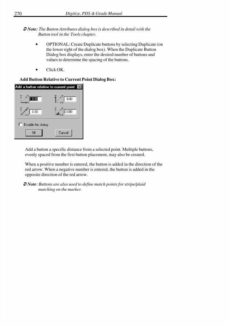
7/28/2019 OptiTex PDS User Manual
http://slidepdf.com/reader/full/optitex-pds-user-manual 293/727
Digitize, PDS & Grade Manual270
! Note: The Button Attributes dialog box is described in detail with the
Button tool in the Tools chapter.
• OPTIONAL: Create Duplicate buttons by selecting Duplicate (onthe lower right of the dialog box). When the Duplicate ButtonDialog box displays, enter the desired number of buttons and
values to determine the spacing of the buttons.
• Click OK.
Add Button Relative to Current Point Dialog Box:
Add a button a specific distance from a selected point. Multiple buttons,
evenly spaced from the first button placement, may also be created.
When a positive number is entered, the button is added in the direction of the
red arrow. When a negative number is entered, the button is added in theopposite direction of the red arrow.
! Note: Buttons are also used to define match points for stripe/plaid
matching on the marker.

7/28/2019 OptiTex PDS User Manual
http://slidepdf.com/reader/full/optitex-pds-user-manual 294/727
Chapter 4: Edit Menu 271
Button Attributes Dialog Box:
The Button Attributes dialog box is described in detail with the Button tool in
the Tools chapter.
Add Slit Lines/Points
Use the Add Slit Lines/Points command to add one or more internals over an
internal or external segment. Notches, buttons, lines or points may be selectedfrom the Add Slit Lines dialog box. Since it is not possible to add notches
over internal segments, us small lines with a Cut attribute instead.
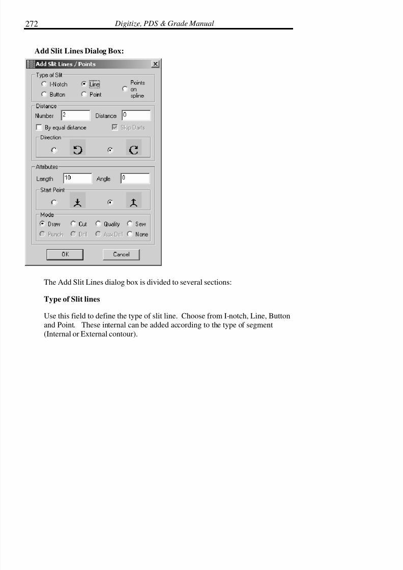
7/28/2019 OptiTex PDS User Manual
http://slidepdf.com/reader/full/optitex-pds-user-manual 295/727
Digitize, PDS & Grade Manual272
Add Slit Lines Dialog Box:
The Add Slit Lines dialog box is divided to several sections:
Type of Slit lines
Use this field to define the type of slit line. Choose from I-notch, Line, Buttonand Point. These internal can be added according to the type of segment
(Internal or External contour).

7/28/2019 OptiTex PDS User Manual
http://slidepdf.com/reader/full/optitex-pds-user-manual 296/727

7/28/2019 OptiTex PDS User Manual
http://slidepdf.com/reader/full/optitex-pds-user-manual 297/727
Digitize, PDS & Grade Manual274
Mode
This field refers to the attribute attached to the internal, concerning the output
device.
Add Points for Notches
From the Edit menu, select Add Points for Notches, and Grading points are
added to existing notches on All Pieces in File, All Pieces in Working Area,All Highlighted Pieces (select + Shift in Piece Bar), or Current Piece Only.
Align Points
The Align Points command aligns a selected group of points horizontally,
vertically, or by a specified angle.
When choosing the Align Points command, more than one point must be
selected.
To select points, click and drag the cursor clockwise along the piece contour
until the appropriate points are selected (select points in a clockwise direction).
To Align Points:
• Click and drag to select the points to be aligned.
• From the Edit Menu choose Align Points. The Align Pointsdialog box is displayed.
• Click on the alignment mode: Horizontal, Vertical, or enter avalue in the angle filed and click on Angle to.
• The points are aligned.

7/28/2019 OptiTex PDS User Manual
http://slidepdf.com/reader/full/optitex-pds-user-manual 298/727
Chapter 4: Edit Menu 275
! Note: The Points will move to match the first point selected.
! Tip: To select points in a counter clockwise direction hold down the Shift
key while selecting each point.
Round Corner
The Round command is used to create a curved intersection where two linesintersect on a boundary line.
To Create a Rounded Corner:
• Select the intersection point on which to create a roundedcorner.
• Select Round Corner from the Edit Menu.
• Enter a value for the radius of the rounded corner in the dialogbox.
• Click OK.
! Note: This command supports multiple point selection.
! Tip: To undo the rounded corner, select Undo from the Edit menu.
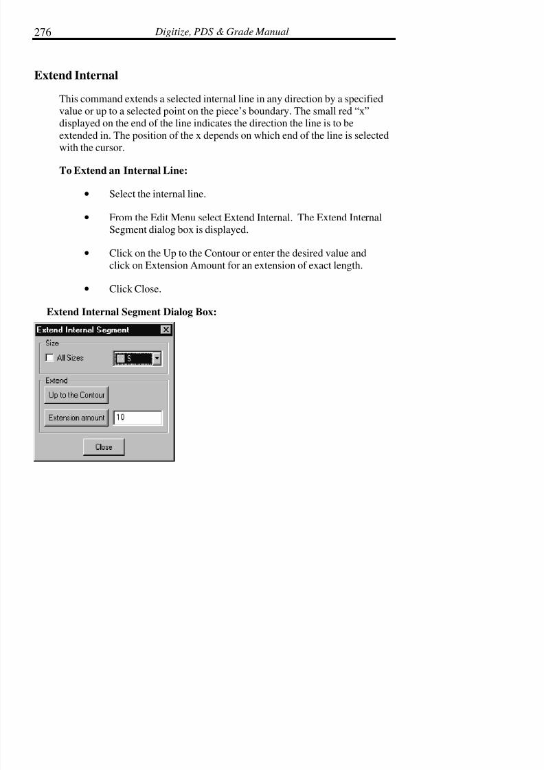
7/28/2019 OptiTex PDS User Manual
http://slidepdf.com/reader/full/optitex-pds-user-manual 299/727
Digitize, PDS & Grade Manual276
Extend Internal
This command extends a selected internal line in any direction by a specified
value or up to a selected point on the piece’s boundary. The small red “x”displayed on the end of the line indicates the direction the line is to be
extended in. The position of the x depends on which end of the line is selectedwith the cursor.
To Extend an Internal Line:
• Select the internal line.
• From the Edit Menu select Extend Internal. The Extend InternalSegment dialog box is displayed.
• Click on the Up to the Contour or enter the desired value and
click on Extension Amount for an extension of exact length.
• Click Close.
Extend Internal Segment Dialog Box:

7/28/2019 OptiTex PDS User Manual
http://slidepdf.com/reader/full/optitex-pds-user-manual 300/727
Chapter 4: Edit Menu 277
Size
Select All Sizes to extend the line for all sizes, or select an individual size by
clicking the drop down arrow to the right of the All Sizes option.
Up to the Contour
Click on this button to extend the selected inner line to the perimeter of the
piece. The side extended will be the selected end of the element.
Extension Amount
Click on this button to extend the selected inner line by a specific amount.Enter the amount in the field next to Extension Amount. The side extended
will be the selected end of the element.
Segment
Use the Segment command to mark a selected shape or segment of a piece,
copy it, and paste it to another location. The Paste tools can be used on the
same or a different piece in the current style file or in a different style file. Thecommands, Copy, Show, Paste Proportional, Paste Notches, Paste Grading,
Paste Between Two Points, and Paste Internal are available within Segment in
the Edit menu.
! Note: An external segment can by copied and paste as an internal to any
piece, also with its grading.

7/28/2019 OptiTex PDS User Manual
http://slidepdf.com/reader/full/optitex-pds-user-manual 301/727
Digitize, PDS & Grade Manual278
Copy:
Use Copy to copy a shape or segment to the clipboard.
To Copy a Segment:
• Select the segments that will be copied by dragging the cursorfrom the first point of the area to the last point.

7/28/2019 OptiTex PDS User Manual
http://slidepdf.com/reader/full/optitex-pds-user-manual 302/727
Chapter 4: Edit Menu 279
• From the Edit Menu select Segment and then select Copy. Thesegment is now copied onto the clipboard and will remain thereuntil something else is copied to the clipboard.
Show Segment
Use Show Segment to show the segment currently on the Clipboard. TheShow Segment command allows changing the start point of the selection to be
pasted or changing the direction of the shape by using the mirror button.
The Inverse option flips the start point of the segment, marked with an “X” to
the opposite side. The Mirror option mirrors the selected segment, verticallyflipping it around the Y-axis. Both options may be used.
To Show the Segment
• From the Edit Menu select Segment and then select Show. The
Segment Editor dialog box displays and the red “x” marks thestarting paste point of the segment
! Note: The sections are always displayed and pasted in a clockwise
manner.
• Mirror or Invert the selected object as desired.
• Enable Use Notches to paste notches with the segment.
• Click OK.
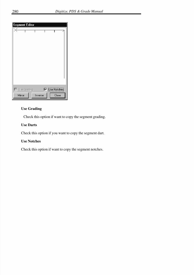
7/28/2019 OptiTex PDS User Manual
http://slidepdf.com/reader/full/optitex-pds-user-manual 303/727
Digitize, PDS & Grade Manual280
Use Grading
Check this option if want to copy the segment grading.
Use Darts
Check this option if you want to copy the segment dart.
Use Notches
Check this option if want to copy the segment notches.

7/28/2019 OptiTex PDS User Manual
http://slidepdf.com/reader/full/optitex-pds-user-manual 304/727
Chapter 4: Edit Menu 281
Paste Segment Proportional
Use the Paste Segment Proportional command to paste the copied segment
between two selected points. The copied segment can be placed between any
two points, or between any number of points. The copied segment will be
inserted between the points in a clockwise direction, keeping its shaperegardless of the original size and scale.
To change the direction or start point of the piece, select the Show Segment
command. The image displays in a dialog box where desired changes can bemade.
To Paste Segment Proportional:
• Copy the desired segment (See steps above).
• Determine the place to paste the copied segment by dragging thecursor from the first point to the last point where the segment isto be copied. The first point selected will match with the one
marked by an “x” in the Segment Editor dialog box (see section
above).
• From the Edit Menu select Segment and Paste Proportional.
The segment is placed proportionally between the two end points regardless of
the size.
! Note: When using Paste Proportional, the pasted segment becomes part of
the piece’s boundary, not an internal line.
Paste Notches
Use this option if you want to copy only the segment notches with the segment
contour.

7/28/2019 OptiTex PDS User Manual
http://slidepdf.com/reader/full/optitex-pds-user-manual 305/727
Digitize, PDS & Grade Manual282
Paste Darts
Use this option if you want to copy only the segment darts with the segment
contour.
Paste between Two Points
Paste Between Two Points inserts or pastes a segment that is copied to the
clipboard using Copy Segment command in the Edit menu. The Paste betweenTwo Points command allows copying a segment to two internal points or
between one internal point and one perimeter point.
! Note: This command differs from the Paste Proportional command in the
Edit menu. The differences that Paste Between Two Points allows
copying a segment as an internal line on the piece. Paste
Proportional only allows copying a segment to the boundary of the
piece.
To Paste between Two Points
• Copy the desired segment (See steps above).
• From the Edit Menu, select Paste Between Two Points. Aspecial cursor will display.
• Use the cursor to select the two points between which thesegment will be pasted. Click the first point, move the cursor to
the second point (even if it is an internal point), and click again.
• The chosen segment is copied and pasted between the twoselected points.

7/28/2019 OptiTex PDS User Manual
http://slidepdf.com/reader/full/optitex-pds-user-manual 306/727
Chapter 4: Edit Menu 283
Paste As an Internal Contour
Paste As an Internal Contour inserts or pastes a segment that is copied to the
clipboard using Copy Segment command in the Edit menu. The Paste As an
Internal Contour command allows copying a segment as an internal from
either an internal point or a perimeter point.
To Paste As an Internal Contour:
• Copy the desired segment (See steps above).
• Determine the place to paste the copied segment by dragging thecursor from the first point to the last point where the segment isto be copied. The first point selected will match with the one
marked by an “x” in the Segment Editor dialog box (see section
above).
• From the Edit Menu select Segment and Paste As an InternalContour.
Make Pieces
Select the Make Pieces command to create Rectangles, Polygons or Circles.This is extremely useful when drafting new pieces.
To Make Pieces:
• From the Edit Menu select Make Piece.
• Choose the type of piece to be made: Rectangle, Polygon orCircle. A dialog box displays for the appropriate selection.
• Enter the desired values.

7/28/2019 OptiTex PDS User Manual
http://slidepdf.com/reader/full/optitex-pds-user-manual 307/727
Digitize, PDS & Grade Manual284
• Click OK.
The Rectangle, Polygon or Circle display in the Piece Display Bar after it is
created.
Make Rectangle Dialog Box:
Enter the desired values for the Length and Width of the new piece. The new
piece displays in the Piece Display Bar.
Make Polygon Dialog Box:
Enter the desired values for the Number of Points for the Polygon, the Radiusand the Angle. The new piece displays in the Piece Display Bar.

7/28/2019 OptiTex PDS User Manual
http://slidepdf.com/reader/full/optitex-pds-user-manual 308/727
Chapter 4: Edit Menu 285
Make Circle Dialog Box:
Enter the desired values for the Number of Points that will be displayed on the
Circle, the Radius and the Angle. The new piece will be displays in the PieceDisplay Bar.
Video
It is possible to attach an *.AVI Video file to points, buttons, seaming, darts,etc. It can be used for training purposes or to pass specific instructions per a
point.
Click a point and choose the Video option. Look for the right *.AVI file to
attach to the point.
To play the video file, just choose the point again and play the video.

7/28/2019 OptiTex PDS User Manual
http://slidepdf.com/reader/full/optitex-pds-user-manual 309/727
Chapter 5: Piece Menu 287
Chapter 5: Piece Menu
The Piece menu is used for editing and changing the attributes of pattern
pieces. To choose one of the Pieces menus commands, click Piece and drag
the mouse to the desired command.
Info (Ctrl + I)
Use the Info command to display or modify information for the selected piece.
Information such as the piece name, size, description, orientation and folding
attributes are defined and changed using the Piece, Information command.
! Note: Each DSN file represents one style with all the pieces and sizes
necessary to make one complete item.
! Tip: Access the Piece Info dialog box quickly by double clicking on the
piece or click on the Ctrl key + I.
! Tip: Use Global Info to set up the defaults or most commonly used
parameters on all pieces and then use Info to individually change
each piece.
To Define the Pattern Piece Info:
• Select the piece.
• From the Piece menu choose Info or double click the piece.
• When the Pattern Information dialog box is displayed, enter thedesired information.
• Click Apply.
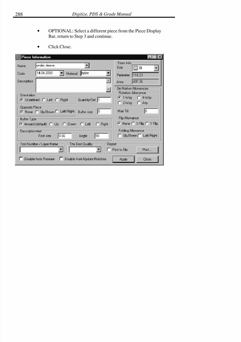
7/28/2019 OptiTex PDS User Manual
http://slidepdf.com/reader/full/optitex-pds-user-manual 310/727
Digitize, PDS & Grade Manual288
• OPTIONAL: Select a different piece from the Piece DisplayBar, return to Step 3 and continue.
• Click Close.

7/28/2019 OptiTex PDS User Manual
http://slidepdf.com/reader/full/optitex-pds-user-manual 311/727
Chapter 5: Piece Menu 289
! Tip: For changes to be applied, be sure to use the Apply button after piece
info has been entered for each piece.
Piece Info Dialog Box:
Name
Name defines the name of the selected pattern piece. If no name is defined, a
numeric name such as 1, 2, 3, etc. is assigned If Close is selected beforeclicking Apply or Enter, the name change is not made. The name of the piece
displays in the Piece Display Bar along the top of the screen.
Code
The code field is used to define a piece code. Some companies use this field to
define a serial number or code number for identifying the piece type. When the
piece is placed in a marker, it is optional to plot or not plot the code on the
piece.
Description
Description allows a description or other important information about the
selected piece to be entered. The description is shown in the printed
information report. When the piece is placed in a marker, it is optional toinclude the description on the piece. This is a helpful feature for relaying
information to a manual cutter.
Quantity/Set
Copies define how many of the selected piece is needed to make one completeitem (style).
Typically, one of each dimensionally like piece is drafted or digitized into a
design file. For example, a man’s dress shirt style is constructed using one
back piece, two front pieces, and two sleeve pieces. However, only one front

7/28/2019 OptiTex PDS User Manual
http://slidepdf.com/reader/full/optitex-pds-user-manual 312/727
Digitize, PDS & Grade Manual290
and one sleeve piece are drafted or digitized. To create the second piece of the
front piece and the sleeve piece, enter a 2 in the Copies field. When the file isloaded in the marking program for marking layout, each size ordered will
contain 2 sleeves and two fronts.
! Note: If the value in the Quantity field is zero (0), this piece does not
appear in the marker file.
Material
Material defines the type of fabric for the selected piece (lining, self, contrast,
etc.). It is best to use general terms for material such as “base,” “lining”, “A,”etc., because if a garment or another product is made in linen one year and in
fleece another year, the user can still use “base” or whatever the main
fabrication was termed the first time.
The Best Quality
This feature is currently being developed. Best Quality relates to defining
areas of best quality for leather cutting.
Buffer Size
Buffer defines a buffer around the entire piece at marker making time. Thisfeature is often used when die cutting. When a buffer is defined on a piece, a
<B> is displayed in the Size List Box in the Marking program for easily
identifying which pieces are using a buffer.
! Note: Buffers can also be added at marker making time.
If a buffer value is specified, the size of the piece is increased around its
contour. However, when nesting has been completed in marker making,
the buffering may be removed. The piece returns to its true dimensions within
the marker, but an invisible buffer remains around the piece.

7/28/2019 OptiTex PDS User Manual
http://slidepdf.com/reader/full/optitex-pds-user-manual 313/727
Chapter 5: Piece Menu 291
! Note: Before changing the buffering of a piece, check the working units to
ensure consistent use of one type of working unit (inches,
centimeters, etc.). Be careful not to mix working units .
Max Tilt
Max Tilt establishes how much a piece may be tilted on the marker in order toconserve material. For example, a value of .5” allows the piece to be tilted up
to .5” on the marker.
Size Info
Size Info displays the net area and perimeter for each piece and all sizes of the
piece. To view piece areas and perimeters for other sizes, scroll down in thesize box to the desired size and click the mouse button. The area for this size
displays in the corresponding box.
Rotate Allowance
Rotate Direction controls the ability to rotate the piece on the marker.
• One-way: Always the same direction (0ø), no Rotation.
• Two-way: Rotate any direction in 180ø angles.
• Four-way: Rotate any direction in 90ø angles.
• Any-way: Rotate any direction.
Orientation
Select from Left, Right Both or leave the Orientation as undefined. The Bothoptions are important when there are two copies of the same piece (for
example, a front) and one of them is the mirror of the other. To define the
current piece with both parts, select Both and the second piece is automatically

7/28/2019 OptiTex PDS User Manual
http://slidepdf.com/reader/full/optitex-pds-user-manual 314/727
Digitize, PDS & Grade Manual292
mirrored. The software verifies that the correct number and orientation of
these pieces is entered. Use Left or Right if only a left or right oriented piece isrequired.
Buffer Type
Buffer Type can be indicated here: Around, Up, Down, Left & Right of thepiece.
Opposite Piece
OptiTex Version 8 "Opposite Piece" filed is enhancement of previous OptiTex
versions "Orientation" filed.
Opposite Piece filed is used only when the selected piece quantity is more then
one. You can use Opposite Piece utility for three purposes:
•For marker making.
• Arrange for plot command.
• Scatter Piece command.
Use the opposite piece option when the selected piece have left and right side
while the piece and the "Flip Allowance" is none or when the selected piecequantity is more then one.
This option gives the piece the ability to be flipped on the marker table.

7/28/2019 OptiTex PDS User Manual
http://slidepdf.com/reader/full/optitex-pds-user-manual 315/727
Chapter 5: Piece Menu 293
Both command uses in the marker making arrange to plot command and
scatter piece command.
Both commands maintain the "Orientation" filed left and right order.
The difference is on the flipped direction as shown bellow.
Flip Allowance
Enabling the Flip option allows the piece to be flipped in the up, down, left,
and right directions. If the piece fits better into the marker flipped, the
software automatically flips the piece to conserve material for higher
efficiency. Use the U\R icon to flip pieces in the marker area. When piece isdefined with Flip Allowed, a <M> is displayed in the Size List Box in the
marker making program.
Description Text
Here you can set the font size as well as an angle of the description text of the
piece.

7/28/2019 OptiTex PDS User Manual
http://slidepdf.com/reader/full/optitex-pds-user-manual 316/727
Digitize, PDS & Grade Manual294
Disable Auto Reseam
This box can be checked in order to disable auto reseam option on this piece
only.
Disable Auto Update Notches
This box can be checked in order to disable auto update notches option on this
piece only.
Folding Allowed
Folding Allowed Defines if a piece may be folded in the up/down or left/rightdirections in the marker. When the box is checked, the piece is defined as
foldable in the marker. Folding is commonly used for Tubular Marking (see
Marker Definitions in the Marker Chapter).
When the piece is defined with Up/Down Folding allowed, a <U> is displayedin the Size List Box next to the piece in the Marking program.
When a piece is defined with Left/Right Folding allowed, <S> is displayed inthe Size List Box next to the piece in the Marking program.
Print Report
This command prints a summary report of the information defined in the PieceInformation dialog box. To change the fonts, use the Fonts option in the
Options Menu.
Apply
This option must be selected in order to apply changes for each piece. If Apply
is not selected, none of the specified changes are made.

7/28/2019 OptiTex PDS User Manual
http://slidepdf.com/reader/full/optitex-pds-user-manual 317/727
Chapter 5: Piece Menu 295
Global Info
While Piece Info (above) modifies attributes only for each currently selectedpiece, Global Info modifies attributes for all pieces in the open design file.
Use this command to define commonly used information. Global Info setsdefault settings for Piece Info.
To Define the Global Info:
• From the Piece menu choose Global Info.
• When the Global Pattern Information dialog box displays, enterthe desired information.
• Click SET for each option that is changed.
• Click Close.
Global Piece Information Dialog Box:
Most of the options listed in the Global Info dialog box are the same as those
in the Piece Info dialog box. Refer to the preceding section for more
information about the different options.

7/28/2019 OptiTex PDS User Manual
http://slidepdf.com/reader/full/optitex-pds-user-manual 318/727
Digitize, PDS & Grade Manual296
Style Name
The Style Name is different from the piece description (in Piece Info). TheStyle Name is used to define a name for the style. The style name can be
plotted on every piece in the marker, while the DSN file name cannot beplotted on pieces in the marker.

7/28/2019 OptiTex PDS User Manual
http://slidepdf.com/reader/full/optitex-pds-user-manual 319/727
Chapter 5: Piece Menu 297
Style Area and Dimension
The Style Area and Dimension command displays all area and perimeter
values for each piece in the open design file. Area and perimeter values aredisplayed according to material type and size.
! Note: This option is the first step of data transfer between SGS grading
software, SGS marking software, and Dennison’s Optiplan 8.
(Dennison’s Optiplan 8 is a complete Pre Calculations and
Optimization program for the advanced cutting room).
Style Area and Perimeter Values Dialog Box
The information in this dialog box can be viewed and printed according toeach individual size and material type. This information can not be changed
through this dialog box; it reflects information that has been entered in both
the Piece Info dialog box and the Global Info dialog box. To make changes,
use the Piece Info and the Global Info dialog boxes.
7/28/2019 OptiTex PDS User Manual
http://slidepdf.com/reader/full/optitex-pds-user-manual 320/727
Digitize, PDS & Grade Manual298
Material
Click the drop down arrow in the material box to select the material group for
which to view the area and perimeter information.
Size
Click the drop down arrow in the size box to select the size for which to view
the area and perimeter information.
This material only
Use this option to print report according to material type that is selected on the“Material” windows.
Print Report
Use this command to print a report of all the sizes and material groups in theopen design file. Change fonts in the Options menu under Fonts.

7/28/2019 OptiTex PDS User Manual
http://slidepdf.com/reader/full/optitex-pds-user-manual 321/727
Chapter 5: Piece Menu 299
Global Change Internals
The global changes for internal option is similar to the Global Change Internal
Parameters option in the Marking program. This dialog box allows changingthe parameters on any type of internal element including notches, darts, texts,
drills, etc. The Left side of the box is for selecting the type of internal that is tobe changed for all pieces (or selected pieces) within the DSN file.
The Right side of the box is for selecting how the elements indicated on theleft should be modified. For example, on the left, Notches and All may be
selected. On the right, V may be selected. This would change all notches in the
DSN file to V notches at one time.

7/28/2019 OptiTex PDS User Manual
http://slidepdf.com/reader/full/optitex-pds-user-manual 322/727
Digitize, PDS & Grade Manual300
Use the Piece section at the center top of the box to select which pieces the
changes should effect. To change all pieces, use the All option. To changeonly the pieces in the working area, use On the Working Area. To change
only the selected piece, use the Current Only option.
Global Notch GradingThis command gives you the option to change the notch grading on all the
pieces or selected piece only.
In order to apply new values on the notches select the parameters in dialogbox.

7/28/2019 OptiTex PDS User Manual
http://slidepdf.com/reader/full/optitex-pds-user-manual 323/727
Chapter 5: Piece Menu 301
Order of Internals
Select the Holes and Internal Contours command to define or change the cut
order cut direction of internal cutouts.
Modify
This command has 5 options to modify selected piece: Rotate, Rotate to Initial
Baseline, Flip Horizontal, Flip Vertical and Mirror.
Rotate
Select the Rotate command to rotate a piece, internal element or baseline by a
specified number of degrees to the left or right.
7/28/2019 OptiTex PDS User Manual
http://slidepdf.com/reader/full/optitex-pds-user-manual 324/727
Digitize, PDS & Grade Manual302
To Rotate a Pattern Piece:
• Select the piece to rotate.
• From the Piece menu choose Rotate.
• When the Rotate Piece or Inner Element dialog box displays,check the Piece box.
• Enter the desired rotation value.
• Select the rotation direction, left or right.
! Note: The selected piece rotates each time the Left or Right button is
selected.
• Click OK.
! Note: The piece and the base line rotate as if they are locked together
unless the Piece Over Base option is selected.
To Rotate a Selected Element:
• Select an internal element (internal line, text, circle, etc.).
• From the Piece menu choose Rotate.
• When the Rotate Piece or Inner Element dialog box is displayed,check the Selected Element box.
• Enter the desired rotation angle.
• Select the rotation direction, left or right.

7/28/2019 OptiTex PDS User Manual
http://slidepdf.com/reader/full/optitex-pds-user-manual 325/727
Chapter 5: Piece Menu 303
! Note: The selected element rotates each time the Left button or Right
button is selected.
• Click OK.
To Rotate the Baseline:
• Select the baseline or the piece.
! Note: The outcome of Rotate when using the Baseline Only option is the
same regardless of whether the baseline or the entire piece is
selected.
• From the Piece menu choose Rotate.
• When the Rotate Piece or Inner Element dialog box is displayed,check the Baseline box.
• Enter the desired rotation value.
• Select the rotation direction, left or right.
! Note: The piece rotates and the baseline remains in its original position
each times the Left or Right button is selected.
• Click OK.

7/28/2019 OptiTex PDS User Manual
http://slidepdf.com/reader/full/optitex-pds-user-manual 326/727
Digitize, PDS & Grade Manual304
Rotate Piece or Inner Elements Dialog Box:
Angle
The Angle determines how far to rotate the piece by degrees. Any rotation
value can be entered.
Piece
Enable this option to rotate the entire piece.
Selected Element
Enable this option to rotate only the selected internal element. The selected
element can be an internal line, text, or circle.
Baseline Only
Select this option to rotate the pattern piece around the base line. The base line
will remain anchored in its original position.
Rotate Left and Rotate Right
Left or right determines the direction the selected element or piece will rotate.The selected element rotates each time one of these options is selected.

7/28/2019 OptiTex PDS User Manual
http://slidepdf.com/reader/full/optitex-pds-user-manual 327/727
Chapter 5: Piece Menu 305
Rotate to Initial Base Line
The Rotate to Initial Base line command be used to rotate the piece back to its
original positioning. The base line, or grain line, is a line (usually horizontal)which ensures the placement of the piece is in the correct direction on the
screen and on the marker.
To Rotate to Initial Base line:
• Select the piece to re-orient.
• From the Piece menu choose Rotate to Initial Base Line.
• From the Piece menu choose Rotate to Initial Base Line.
The pattern piece is returned to its original position, and all internal elements
are rotated along with the piece. This command also sets the current base line
to a horizontal position. The ratio between the base line and the contourremains constant.
Flip Horizontal
This command flips the current pattern piece 180ø along the Y-axis (Back and
Forth).
Flip Vertical
This command flips the current pattern 180ø along the X-axis (Up and Down).

7/28/2019 OptiTex PDS User Manual
http://slidepdf.com/reader/full/optitex-pds-user-manual 328/727
Digitize, PDS & Grade Manual306
Mirror
This command creates a new piece exactly the same as the selected pieceexcept the new piece has two symmetrical halves made from the original
piece. Note that this command creates an exact symmetric duplicate, which is
the same on both sides.
To Mirror a Pattern Piece:
• Select two consecutive points by clicking on the first point, thendragging (clockwise) to the next point.
• From the PIECE menu choose MIRROR.
A new piece is created which is symmetrically placed according to the selected
points. The new piece displays in the furthermost right-hand box in the Piece
Display Bar. See the diagram below.
Drag the courser from theright point to the left point
to select the mirror line

7/28/2019 OptiTex PDS User Manual
http://slidepdf.com/reader/full/optitex-pds-user-manual 329/727
Chapter 5: Piece Menu 307
! Note: The symmetric line will be shared by all sizes. If the original piece is
graded, the grading values are also duplicated.
! Tip: The Mirror command may only be used when 2 points are selected, as
mirroring a piece must occur along a straight line. All straight lines
require only two points. If a piece has three or more points along the
mirror line, it may be necessary to delete these extra points.
! Note: A symmetric line in a mirrored piece means that this piece has an
“equal group” in the“Equal Segment Groups” dialog box under
Design menu.
The new mirror piece

7/28/2019 OptiTex PDS User Manual
http://slidepdf.com/reader/full/optitex-pds-user-manual 330/727
Digitize, PDS & Grade Manual308
! Note: You can find more detailed information on “Equal Segment” feature
in chapter 9 Design menu.
Scale and Shrink
The Scale and Shrink command enlarges or reduces the actual piece size in the
X or Y direction by a specified percentage. If the piece is graded first, thenscaled, the graded sizes are scaled along with the base size. If the piece is
scaled first and then graded, the graded sizes are not scaled.
The Scale & Shrink command is mainly used when working with materialsthat have a shrink or stretch factor. This command is also used when digitizing
a miniature pattern from another source (i.e. a magazine or book). The Scale
command is used to enlarge the pattern to its actual size.
To Scale or Shrink:
• Select the desired pattern piece. & from the Piece menu chooseScale And Shrink.
• When the Scale and Shrink Options dialog displays enter thevalues to scale the piece.

7/28/2019 OptiTex PDS User Manual
http://slidepdf.com/reader/full/optitex-pds-user-manual 331/727
Chapter 5: Piece Menu 309
! Note: Enter a -50% value to shrink the piece to half of the original size.
Enter 50% to scale the piece double its original size.
• Select the correct option of scaling either the selected piece, allpieces in the file, or only pieces on the working area.
! Tip: Use the Scale All command to scale all the pattern pieces in the Piece
Display Bar.
• Click OK to scale the pieces.

7/28/2019 OptiTex PDS User Manual
http://slidepdf.com/reader/full/optitex-pds-user-manual 332/727
Digitize, PDS & Grade Manual310
! Tip: Use the Measure Tool to verify the changes in size between the
original size and the scaled size.
! Tip: “Selected Piece/Contour Segment” option will scale up/down the
selected piece perimeter.
! Tip: “Selected Specials Only” option will scale up/down the selected
internal segment.
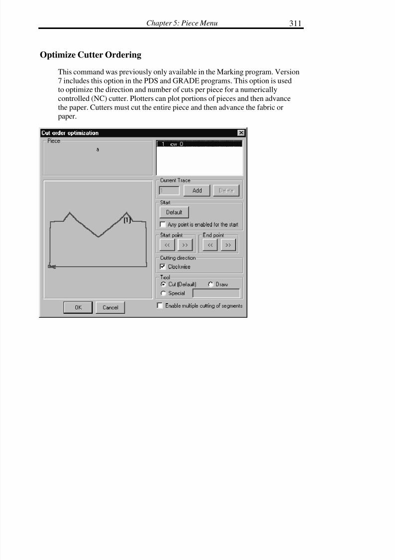
7/28/2019 OptiTex PDS User Manual
http://slidepdf.com/reader/full/optitex-pds-user-manual 333/727
Chapter 5: Piece Menu 311
Optimize Cutter Ordering
This command was previously only available in the Marking program. Version
7 includes this option in the PDS and GRADE programs. This option is usedto optimize the direction and number of cuts per piece for a numerically
controlled (NC) cutter. Plotters can plot portions of pieces and then advancethe paper. Cutters must cut the entire piece and then advance the fabric orpaper.
7/28/2019 OptiTex PDS User Manual
http://slidepdf.com/reader/full/optitex-pds-user-manual 334/727
Digitize, PDS & Grade Manual312
Current Trace
Indicates the number of separate cuts an automatic cutter will make on a piece.
In the example above there is only one cut that starts and ends at the samelocation.
Start
Start is used to set the start point at the default point (point #1 of a pieceusually located at the lower left corner). Use the Any Point option if the piece
can be cut starting at any point on the piece.
Start Point/End Point
Start Point/End Point are used to arrow the beginning or the end of the cut to
different locations. To back up the start point, or to extend the end point of the
cut to another point, use these arrows.
Cutting Direction
Cutting Direction is used to make the cut either clockwise or counterclockwisein direction.
Tool
Tool is used to set the type of tool to be used on the piece. For example, if thepiece is to be cut, the tool is set as cut. If the piece is only to draw using a pen,
set as draw.
Points Cleanup
Points Cleanup is used to remove unnecessary/extra points on a pattern piece.
Use this command when importing pattern pieces or when the pattern pieceboundary is digitized with too many points.

7/28/2019 OptiTex PDS User Manual
http://slidepdf.com/reader/full/optitex-pds-user-manual 335/727
Chapter 5: Piece Menu 313
To Delete Duplicate Points:
• Select the desired pattern piece.
• From the Piece menu choose Del. Duplicate Points.
• When the Tolerance dialog box displays, enter the desiredtolerance value. The tolerance setting refers to how much a
piece is allowed to change dimensionally. For example, if the
piece can tolerate a change of .125”, enter .125 in the tolerancebox.
• Select the appropriate option for which to apply the tolerancevalue (All Pieces in the File, All Pieces in the Working Area, or
Current Piece Only).
7/28/2019 OptiTex PDS User Manual
http://slidepdf.com/reader/full/optitex-pds-user-manual 336/727
Digitize, PDS & Grade Manual314
All extra points are deleted maintaining that the piece not change dimensional
beyond the tolerance setting.
! Tip: If the Tolerance value was entered incorrectly, select Undo from the
Edit menu and retry the command.
Set (0,0) Point
Select the Set (0,0) Point command to change the start measuring point for the
selected pattern piece in the working area. This command is used in
conjunction with the Coordinates command in the Display menu. Thiscommand is particularly useful during the freehand pattern editing or drafting
because it shows the position of the cursor relative to the 0,0 point in any delta
X/Y direction.
To Set (0,0) Point:
• Select the point to use as the new start point.
• From the Piece menu choose Set (0,0) Point.
! Note: Changing the 0,0 point causes the grid to align itself to the 0,0 point.
(To view the grid, check the Grid and Stripes option in the Options
and pull down menu).
Start Point
Select this command to define which grading point will become the first point.
The first grading point and the order of all other grading points is especiallyimportant when using All Point (Global) Grading rules. To display point
numbers, select Point Numbers from the Display pull down menu.

7/28/2019 OptiTex PDS User Manual
http://slidepdf.com/reader/full/optitex-pds-user-manual 337/727
Chapter 5: Piece Menu 315
! Note: While using the All Point Grading (Global) rules, or the Graded
Nest command, point numbers play an important role.
! Note: The first point of a pattern piece defaults to the first digitized point.
If patterns are always digitized starting from the lower left corner
point, than this point will always be the first point
To Set the Start Point:
• Select the point to set as the first piece point.
• From the Grading Menu choose Start Point.
Base Parallel to Segment
Use Base Parallel to Segment to realign the base line to another internal line orto a line segment on the piece’s boundary.

7/28/2019 OptiTex PDS User Manual
http://slidepdf.com/reader/full/optitex-pds-user-manual 338/727
Digitize, PDS & Grade Manual316
To Make the Base Line Parallel to a Segment:
• Select the two point internal line or line segment to which thebase line will be aligned. Using the example above, select from
point #2 to point #1.
• From the PIECE menu, select BASE PARALLEL TOSEGMENT.
! Note: If you select point 1 and 2 the base line direction will be rotated
180° .
base line
center fornt line
! Note that the base line is now parallel to the center front line.
• Now the base line is parallel with the center front line. It may benecessary to use he Rotate to Initial Base Line command to
rotate the piece back on the straight of grain. The Rotate toInitial Base Line command is also available in the Piece Menu.
The diagram below shows the newly aligned pattern piece.
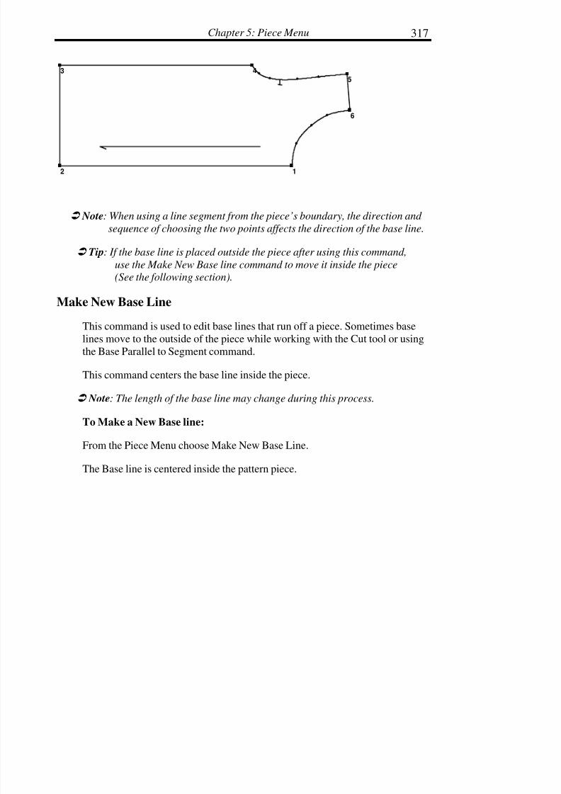
7/28/2019 OptiTex PDS User Manual
http://slidepdf.com/reader/full/optitex-pds-user-manual 339/727
Chapter 5: Piece Menu 317
12
3 4
5
6
! Note: When using a line segment from the piece’s boundary, the direction and
sequence of choosing the two points affects the direction of the base line.
! Tip: If the base line is placed outside the piece after using this command,
use the Make New Base line command to move it inside the piece
(See the following section).
Make New Base Line
This command is used to edit base lines that run off a piece. Sometimes base
lines move to the outside of the piece while working with the Cut tool or using
the Base Parallel to Segment command.
This command centers the base line inside the piece.
! Note: The length of the base line may change during this process.
To Make a New Base line:
From the Piece Menu choose Make New Base Line.
The Base line is centered inside the pattern piece.
7/28/2019 OptiTex PDS User Manual
http://slidepdf.com/reader/full/optitex-pds-user-manual 340/727
Digitize, PDS & Grade Manual318
Guideline Parallel
This command gives the option to add a guideline as parallel to selectsegment.
To create a parallel guideline:
• Select a segment between two points.
• From PIECE pull down menu choose GUIDELINE PARALELLcommand.
• The guideline wills appears on the working area.
Seam
The Seam command contains five different options: Reseam, Update Notches,
Work on Seam, Switch all Pieces to Cut, Switch all Pieces to Sew, Unseam.Use Seam when seam allowance has been applied to a piece or pieces within
the current design file.
! Note: Creating Seam Allowance is described in detail with the Seam
Allowance tool in the Tools chapter.
! Note: To view or not to view seam allowances, select Seamed Piece from
the Display pull down menu.
! Tip: It is most effective to add seam allowances to pieces after the piece
has been designed, edited, and graded.

7/28/2019 OptiTex PDS User Manual
http://slidepdf.com/reader/full/optitex-pds-user-manual 341/727
Chapter 5: Piece Menu 319
Reseam (F6)
When edits are made to a pattern piece after seam allowance has been applied,
and the Auto Reseam option in the Options Menu is turned off, the Reseam(F6) command can be used to update the seam allowance so that it follows the
new perimeter line. See the diagram below.

7/28/2019 OptiTex PDS User Manual
http://slidepdf.com/reader/full/optitex-pds-user-manual 342/727
Digitize, PDS & Grade Manual320
Update Notches
This command allows you to update the changes automatically with seam
contour only on notches (without changing piece contour while seam contouris changing
Work on Seam (F5)
This command switches between boundary lines (sew or cut). The solid line
indicates which line is currently selected. It is important to make sure that the
outer most lines (the cut lines) are solid before the design file gets sent intomarker making.
This command tells the computer to either make sew lines solid, or make thecut lines solid. The solid line is the line that the computer recognizes as the
active line. Edits can only be made to the active (solid) line.

7/28/2019 OptiTex PDS User Manual
http://slidepdf.com/reader/full/optitex-pds-user-manual 343/727
Chapter 5: Piece Menu 321
Depending on which line is solid on the selected piece, this option reads either,“Switch to Cut,” or “Switch to Sew.”
! Tip: To see both lines, select Seamed Piece from the Display menu.
The diagram shows an additional example of Cut Lines and Sew Lines.

7/28/2019 OptiTex PDS User Manual
http://slidepdf.com/reader/full/optitex-pds-user-manual 344/727
Digitize, PDS & Grade Manual322
Switch all Pieces to Cut (F5 + Ctrl)
This command tells the computer to make all cut lines (outermost lines) on all
pieces in the current file solid lines. This command is used to eliminate havingto change each piece to cut lines one at a time.
Switch all Pieces to Sew (F5 + Shift)
This command tells the computer to make all sew lines (innermost lines) on all
pieces in the current file solid lines. This command is used to eliminate having
to change each piece to sew lines one at a time.
Unseam
The Unseam command removes seams from all the selected pattern pieces inthe file, all pieces in the working area, or from the current piece only. BE
CAREFUL using this command. If the solid lines are the inside lines, usingthis command results in pieces with dimensions of the inner line. If the solid
lines are on the outside, using this command results in pieces with dimensionsof the outer line. Seam allowance value is lost after using this command.
An example of when TO use this command follows:
Example:
Problem: A clothing style normally sent to contractor A to be sewn has astandard seam allowance of ½”. The same clothing style will be sent to
contractor B to sew. Contractor B uses 3/8” standard seam allowance.
Solution: Use SWITCH ALL TO SEW to make sew line solid. Now use the
UNSEAM command to get rid of all seam allowances in the selected style.Now all pieces will be their actual finished dimensions. Now add the 3/8”
seam allowance to all pieces.

7/28/2019 OptiTex PDS User Manual
http://slidepdf.com/reader/full/optitex-pds-user-manual 345/727
Chapter 5: Piece Menu 323
To Unseam a Piece:
• Select the pattern piece that includes the seam to be removed.
• From the Piece Menu choose Unseam.)
• When the Unseam dialog box displays, select the desired option.
! Note: To replace the seam, the seam allowance must be redefined or use
the Undo command in the Edit menu.
The selected piece(s) will be unseamed.
Walk
Walk is used to verify that seams to be sewn together are the correct lengths.
Most often, seams to be sewn together are identical in length. In cases where
there are pleats, darts, or shirring fullness, sew able seam lengths are still thesame after the dart, pleat, or fullness amount is subtracted. Walking seams
manually is often tedious and inaccurate. The Walk command eliminatestedious seam verification.
There are six functions within the Walk command: Walk Options, Switch
Direction. Walk Mode, Notch Both, Notch Stationary, and Notch Moving.

7/28/2019 OptiTex PDS User Manual
http://slidepdf.com/reader/full/optitex-pds-user-manual 346/727
Digitize, PDS & Grade Manual324
To Walk Seams:
• Lock both piece together be using the Hand tool (The Hand Toolis described in detail in the Tools chapter). Select the grading
point (with the move tool) of the moving piece and, put it on thetop of the grading point of stationary piece (see the picture).
! Note: If the two grading points (on both moving & stationary pieces) are
not positioned exactly one on top of the other, the walk tool will be
disabled!
! Note: The moving piece is the piece that is moved with the Hand tool.
• From the PIECE menu, select WALK and then WALK again.The cursor arrow changes to the walk icon (two little feet).
• Touch on one of the seams (either the moving or the stationary)in the walk direction. The pieces rotate according to the
positioning of the cursor on the seam.
• Continue step three until the end of one of the segments isreached.

7/28/2019 OptiTex PDS User Manual
http://slidepdf.com/reader/full/optitex-pds-user-manual 347/727
Chapter 5: Piece Menu 325
• From the PIECE menu, select WALK SETUP to view thedistance walked.
Walk Options
Use Walk Setup to set parameters for walking pieces. Also, use Walk Setup
for checking final seam distances of both the moving and the stationary pieces.
Walk Setup Dialog Box:
Ratio
Use Ratio in order for the computer to automatically account for fullness in
one of the seam lengths to be walked. A ratio value is entered for the movingpiece. The piece that has fullness applied should be established as the moving
piece. The pattern maker can accurately walk the seams while accounting for
the fullness by entering a percent amount to be applied to the piece withfullness (the moving piece). If 30% is entered, the moving piece walks 30%
faster than the piece without fullness (the stationary piece).

7/28/2019 OptiTex PDS User Manual
http://slidepdf.com/reader/full/optitex-pds-user-manual 348/727
Digitize, PDS & Grade Manual326
Step
Use Step to set up the distance to be walked for each step. This option is used
when the left and right arrow keys are used for walking the piece instead of the
walk cursor.
Direction
Check the appropriate box to set up the direction of the walk, clockwise orcounter clockwise.
Skip Darts
Check the Skip Darts box, in order to automatically account for a dart in oneof the seams to be walked.
Distance Moving
The Distance Moving Box displays the total distance of the moving seam.
Distance Stationary
The Distance Moving Box displays the total distance of the stationary seam.
Switch Direction (F11)
The Switch Direction command changes the direction of the walk from inside
to outside.
! Tip: To back up one step, use the Undo command in the Edit menu or use
Ctrl+Z.

7/28/2019 OptiTex PDS User Manual
http://slidepdf.com/reader/full/optitex-pds-user-manual 349/727
Chapter 5: Piece Menu 327
Notch Both (F12)
Use Notch Both to place a notch on both the moving and the stationary seams.When this option is selected, the default notch type is applied to both the
stationary and the moving seams.
Notch Stationary (F12 + Ctrl)
Use Notch Stationary to place a notch on the stationary seam. When this
option is selected, the default notch type is applied to the stationary seam.
Notch Moving (F12 + Shift)
Use Notch Moving to place a notch on the stationary seam. When this option
is selected, the default notch type is applied to the stationary seam.
Fabric and Stripes
The fabric and Stripes feature is used to display fabric patterns on the screenso that the pattern maker can develop the pattern in concordance with the
actual fabric pattern to be used in manufacturing the end product. The SGS
software works with any .BMP file. Actual fabric can be scanned into thecomputer (provided there is access to scanning equipment) and then be pulled
up into the SGS design software.
The overall sequence of procedures necessary to display a fabric patterns on
screen and to relate pieces to the fabric follows:
First, select the fabric pattern. Second, create stripe lines on the screen thatcoincide with the fabric pattern. This step is done using the Grid and Stripescommand in the Options menu. The third step is to relate pieces to the fabric
using the stripe lines.
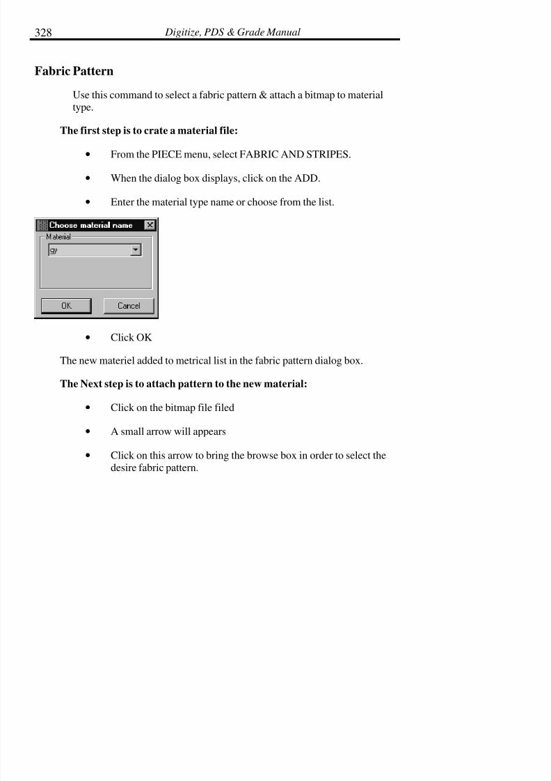
7/28/2019 OptiTex PDS User Manual
http://slidepdf.com/reader/full/optitex-pds-user-manual 350/727
Digitize, PDS & Grade Manual328
Fabric Pattern
Use this command to select a fabric pattern & attach a bitmap to materialtype.
The first step is to crate a material file:
• From the PIECE menu, select FABRIC AND STRIPES.
• When the dialog box displays, click on the ADD.
• Enter the material type name or choose from the list.
• Click OK
The new materiel added to metrical list in the fabric pattern dialog box.
The Next step is to attach pattern to the new material:
•Click on the bitmap file filed
• A small arrow will appears
• Click on this arrow to bring the browse box in order to select thedesire fabric pattern.

7/28/2019 OptiTex PDS User Manual
http://slidepdf.com/reader/full/optitex-pds-user-manual 351/727
Chapter 5: Piece Menu 329
• select the type of the graphic file ( choose between:BMP,JPG,PSD and more)
• Click on the desire file.
• The preview of the pattern now showing on the dialog box.
• Click OK
• The material files save box will appears
• Enter file name in the file name field.
• Click SAVE
• Last : Change the piece material type.
• Open the PIECE INFO dialog box from the piece menu.
• Chose the new material type from the material field.
• Click apply

7/28/2019 OptiTex PDS User Manual
http://slidepdf.com/reader/full/optitex-pds-user-manual 352/727
Digitize, PDS & Grade Manual330
• The piece now will have the pattern that belong to this materialtype
! Note: To apply the fabric selection to the entire screen or to individual
pieces, use the four fabric tools located on the Advance Toolbar
(these tools are covered below).
• The same change can be made in the Global Piece dialog boxfrom the piece menu in order to apply the pattern to the entire
pieces on the working area.

7/28/2019 OptiTex PDS User Manual
http://slidepdf.com/reader/full/optitex-pds-user-manual 353/727
Chapter 5: Piece Menu 331
Hide Fabric Pattern
Hide Fabric Pattern hides a selected fabric pattern from display on the screen.
Show Fabric Pattern
Show Fabric Pattern shows a selected fabric pattern on the screen. The fabric
displays on the entire working area of the screen.
Clip Fabric Pattern
Clip Fabric Pattern shows the selected fabric only on the pieces that aredisplayed in the working area of the screen.
Show Control Points
This tool toggles between displaying the control points of a piece and not
displaying the control points of a piece. Fabric appearance is cleaner when the
control points are hidden from view.

7/28/2019 OptiTex PDS User Manual
http://slidepdf.com/reader/full/optitex-pds-user-manual 354/727
Digitize, PDS & Grade Manual332
Relate Piece to Stripes
The Relate Piece to Stripes is used to help align pieces on the fabric.
Remember to create stripe lines using the Grid and Stripes command in theOptions menu before attempting this step.
To Relate a Piece to Stripes:
• Select the piece to be related.
• Select a point, a notch or an internal button on the piece to useas a reference point. This point is used to align the piece withthe stripe line on the fabric pattern.
• From the PIECE pull down menu, select FABRIC ANDSTRIPES, then select RELATE PIECE TO STRIPES. The
following dialog box displays:
• Enter the distance to place the piece from the stripe line. The
piece is placed according to the selected point. This point
appears as a dark dot in the dialog box. If a zero (0) is entered ineither the X or Y box (depending on which box is not grayed
out), the piece aligns exactly onto the stripe line at the selected
point.
• Click OK when the piece is aligned correctly.
! Note: The piece stays aligned with the stripe lines until the stripes are
removed.

7/28/2019 OptiTex PDS User Manual
http://slidepdf.com/reader/full/optitex-pds-user-manual 355/727
Chapter 5: Piece Menu 333
7/28/2019 OptiTex PDS User Manual
http://slidepdf.com/reader/full/optitex-pds-user-manual 356/727
Digitize, PDS & Grade Manual334
Set Group
Set group is used to group pieces on the screen in relation to stripe lines.
To Set Group:
• Simply place each piece on the screen as desired in relation tostripe lines (use the instructions in the section above).
• Select SET GROUP from the FABRIC menu in the PIECE pullsdown menu.
Pieces are now set within a group related to the stripe lines. This group can be
carried over into the marker-making program.
Ungroup
Use this command to ungroup any previously set groups.
7/28/2019 OptiTex PDS User Manual
http://slidepdf.com/reader/full/optitex-pds-user-manual 357/727
Chapter 6: Grading Menu 335
Chapter 6: Grading Menu
The grading procedure is a necessary stage in the apparel and garment making
industry. Basic grading procedures are the same using the computer as they are
manually on the table. However, manual grading is largely based on theexperience of the designer, pattern maker, and grader. Keep in mind that all
companies grade differently. The grading program designed by SGS providesall the basic grading principles and allows the user to apply them as needed by
their company.
Grading on this system is based on the delta X, Y system. Each grade point is
assigned X and Y values which are displayed in the Grading Table. All
grading commands also are available by Icon for your convenience. Thecommands perform the same function whether they are chosen from the menu,
or by icon.
There are two easy ways to identify icons. The first is to look up the icon inthe Grading pull down menu. Each icon is displayed to the left of itscorresponding command. The second way to identify grading icons is to point
the cursor at the icon. A shadow box with the name of the command will
appear.
! Tip: If you do not use grading, or you are not currently using the grading
package, turn off the display of the Grading Table to enlarge your
working space. This is turned on and off in the View menu under
Grading Table
Values are displayed in the Grading Table whenever a point is selected. Thegrading values are also used to grade internals, like buttons and lines.
! Tip: Copy and paste the grading value of a point and use it on an internal
element.

7/28/2019 OptiTex PDS User Manual
http://slidepdf.com/reader/full/optitex-pds-user-manual 358/727
Digitize, PDS & Grade Manual336
Stack Point
The Stack Point command aligns all graded pieces to a reference point in
either the X or Y direction. This reference point is also called the Nest Point.This command can also be used on an internal point or button.
The Grading software calculates the relative distance for each point and moves
all pattern pieces accordingly. Patterns may be left as they are in their new
position, and grading procedures may be continued.
To return to the initial position, determine a point at which all of the grading
points are positioned in the same location prior to using the Stack command.Re-stack the nest at this predetermined point to return to the initial position. If
no common point is available, simply add a button mark (without grading) to
the piece and use that point as the initial point. The extra button mark may bedeleted later.
To Use a Stack Point:
• Select the point on which to stack the nest.
• From the Grade Menu select Stack Point. The Stack Pointdialog box is displayed.
• Select the desired display mode. Select both the X and the Yfield to stack the nest on exactly one point.
• Click OK.
Stack Along Line
Allows you to stack grading according to a selected line as opposed to onlyone point.

7/28/2019 OptiTex PDS User Manual
http://slidepdf.com/reader/full/optitex-pds-user-manual 359/727
Chapter 6: Grading Menu 337
Load Sizes
This command functions to load the existing size list from an opened rulelibrary file. This command would typically be used in instances such as the
one in the following example:
Example: A base pattern is digitized. The base pattern is to be graded on the
computer and a library of existing rules is to be used.
When loading sizes from a Rule Library to a file that already has a different
size list established, a message box for Load Sizes appears in order to matchthe two different size lists.
First size correspond to First size:
Select this option in order for the sizes in the Existing sizes column tocorrespond to the sizes in the New size column. Therefore, starting with the
First size, the sizes in the Existing sizes list will take on the sizes of the Newsizes, including the designated Base size (marked by the asterisk * in the Newsizes list). If there are more sizes in the Existing sizes list than in the New size
list, they will be deleted after the Load Sizes function is complete.

7/28/2019 OptiTex PDS User Manual
http://slidepdf.com/reader/full/optitex-pds-user-manual 360/727
Digitize, PDS & Grade Manual338
Base size correspond to Selected size:
Select this option in order to specify which of the New sizes is going to be the
base size when loaded.
To Load Sizes:
• Open the rule file to use by selecting Rules from the GradingMenu and then selecting Open Rule Library.
• Select Load Sizes and the sizes from the rule file will display inthe Grading Table size list.
! Note: Make sure that the rules and the base size displayed in the rule
library are compatible to those, which you are going to use.
! Tip: This command can be used to define sizes before starting to digitize a
new style. In this case, create a new style with a dummy piece, i.e. arectangle, complete the steps above, and then digitize the pattern.
Reshape Variation Grading
This command combines both grading fields (size variation) when there are
two different grading sets in the same file.
Select Reshape Variation Grading from the Grading Menu to merge both sets
to a single grading set (the sizes in this new set, will be the result of multiplying the merged sizes one by one).

7/28/2019 OptiTex PDS User Manual
http://slidepdf.com/reader/full/optitex-pds-user-manual 361/727
Chapter 6: Grading Menu 339
Grading Table with Variation Grading:
Copy Grading (Ctrl + G, C)
Use Copy Grading to copy the grading values for both X and Y on a selected
point. The grading will be copied to the clipboard and remains on the
clipboard until another point of grading is copied.
Typically, another point is selected, and the copied rule is pasted onto thenewly selected point.
Relative (Ctrl + G, R)
Relative is used to automatically apply opposite grading on a piece when usingthe Paste command. A check mark next to relative in the Grading menu
indicates that the relative option is turned on.
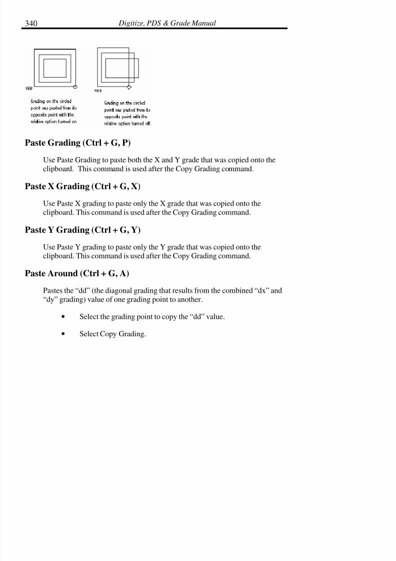
7/28/2019 OptiTex PDS User Manual
http://slidepdf.com/reader/full/optitex-pds-user-manual 362/727
Digitize, PDS & Grade Manual340
Paste Grading (Ctrl + G, P)
Use Paste Grading to paste both the X and Y grade that was copied onto the
clipboard. This command is used after the Copy Grading command.
Paste X Grading (Ctrl + G, X)
Use Paste X grading to paste only the X grade that was copied onto the
clipboard. This command is used after the Copy Grading command.
Paste Y Grading (Ctrl + G, Y)
Use Paste Y grading to paste only the Y grade that was copied onto theclipboard. This command is used after the Copy Grading command.
Paste Around (Ctrl + G, A)
Pastes the “dd” (the diagonal grading that results from the combined “dx” and
“dy” grading) value of one grading point to another.
• Select the grading point to copy the “dd” value.
• Select Copy Grading.

7/28/2019 OptiTex PDS User Manual
http://slidepdf.com/reader/full/optitex-pds-user-manual 363/727
Chapter 6: Grading Menu 341
• Select the grading point to paste the “dd” value.
• Select Paste Around. The “dx” and “dy” values areautomatically assigned values that achieve the “dd” grading.
Flip X Grading (Ctrl + G, F)Flip X Grading reverses the direction of X grading values. If the X value for a
grade point is +1/2” for each larger size, Flip X reverses the X so that it is -1/2” for each larger size.
Flip Y Grading (Ctrl + G, L)
Flip Y Grading reverses the direction of Y grading values. If the Y value for a
grade point is +1/2” for each larger size, Flip Y reverses the Y so that it is -
1/2” for each size larger.
Equal X Grading (Ctrl + G, E)
Use Equal X Grading so that only one value must be entered for an entire sizerange on an even grade. This command eliminates tedious and repetitive
typing.
To Use Equal X Grading:
• Type in the X growth amount for the next larger size from thebase size.
• Move the cursor to the top of the X column in the grading table.
• Click the cursor with the left button one time to highlight theentire X column in black.
• Select Equal X Grading from the Grading Menu or use the

7/28/2019 OptiTex PDS User Manual
http://slidepdf.com/reader/full/optitex-pds-user-manual 364/727
Digitize, PDS & Grade Manual342
Equal X icon.
• All sizes are now equally graded.
Equal Y Grading (Ctrl + G, Q)
Use Equal Y Grading so that only one value must be entered for an entire size
range on an even grade. This command eliminates tedious and repetitive
typing.
To Use Equal X Grading:
• Type in the Y growth amount for the next larger size from thebase size.
• Move the cursor to the top of the Y column in the grading table.
• Click the cursor with the left button one time to highlight theentire Y column in black.
• Select Equal Y Grading from the Grading Menu or use theEqual Y icon.
• All sizes are now equally graded.
Zero Grade (Ctrl + G, Z)
Zero Grade quickly makes all grade values for all sizes, zero in the X and Y
column. This command is commonly used to remove grading from a particularpoint.

7/28/2019 OptiTex PDS User Manual
http://slidepdf.com/reader/full/optitex-pds-user-manual 365/727
Chapter 6: Grading Menu 343
Zero X Grade (Ctrl + G, N)
Zero X Grade quickly makes all grade values for all sizes, zero in the Xcolumn. This command is commonly used to remove grading from a particular
point.
To Use Zero X Grade:
• Change the X grading value in the size box for the next largersize to zero.
• Move the cursor to the top of the X column in the grading table.
• Click the cursor with the left button one time to highlight theentire X column in black.
• Select ZERO X GRADES from the GRADING menu or use the
Zero X icons.
• All sizes are now grading zero in the X direction.
Zero Y Grade (Ctrl + G, O)
Zero Y Grade quickly makes all grade values for all sizes zero in the Ycolumn. This command is commonly used to remove grading from a particular
point.
To Use Zero Y Grade:
• Change the Y grading value in the size box for the next largersize to zero.
• Move the cursor to the top of the Y column in the grading table.
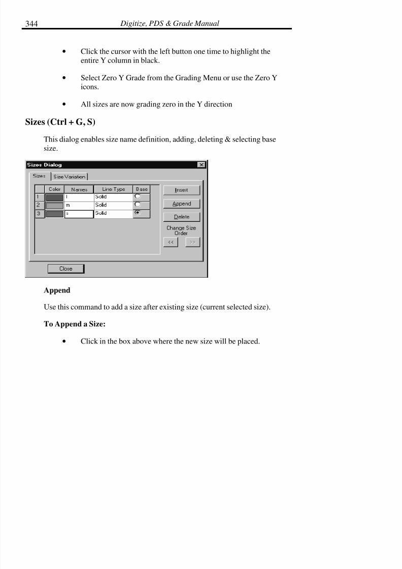
7/28/2019 OptiTex PDS User Manual
http://slidepdf.com/reader/full/optitex-pds-user-manual 366/727
Digitize, PDS & Grade Manual344
• Click the cursor with the left button one time to highlight theentire Y column in black.
• Select Zero Y Grade from the Grading Menu or use the Zero Yicons.
• All sizes are now grading zero in the Y direction
Sizes (Ctrl + G, S)
This dialog enables size name definition, adding, deleting & selecting base
size.
Append
Use this command to add a size after existing size (current selected size).
To Append a Size:
• Click in the box above where the new size will be placed.

7/28/2019 OptiTex PDS User Manual
http://slidepdf.com/reader/full/optitex-pds-user-manual 367/727
Chapter 6: Grading Menu 345
• Select Append.
• Type the size name in the newly created box.
! Note: Some existing grading values may change when inserting sizes.

7/28/2019 OptiTex PDS User Manual
http://slidepdf.com/reader/full/optitex-pds-user-manual 368/727
Digitize, PDS & Grade Manual346
Insert
Use Insert to add a size before an existing size (current selected size).
To Insert a Size:
• Click in the box above where the new size will be placed.
• Select Insert.
• Type the size name in the newly created box.
! Note: Some existing grading values may change when inserting sizes.
Delete
Use this command to delete a size from the current size list.
To Delete a Size:
• Select the size to be deleted.
• Click Delete Size. The dialog box displays asking if you want to
resize the remaining sizes.
• Click Yes to readjust the sizing.
The selected size is deleted and all other sizes are resized accordingly.

7/28/2019 OptiTex PDS User Manual
http://slidepdf.com/reader/full/optitex-pds-user-manual 369/727
Chapter 6: Grading Menu 347
Change Size Order
This command changes the order of the size list without having to retype overa size name.
•
Select the size you would like to move.
• The Change Size Order arrows are now accessible.
• Select the appropriate arrow to switch the selected size with theprevious or following size.
Base Size
Select the Base Size command to redefine the current base size. The base size
is user-defined, and therefore is not always the first size in the list. The basesize is not graded, meaning that the values of its X and Y grade points are
zero.
! Note: The new base size is the actual physical size of the new size name.
For example, if sizes for a design file are S, M, and L, and the base
size is changed from an M to S, the dimensions of the new base size
are the true dimensions of the S.
7/28/2019 OptiTex PDS User Manual
http://slidepdf.com/reader/full/optitex-pds-user-manual 370/727
Digitize, PDS & Grade Manual348
! Note: If the desired outcome is to change the physical size of the base and
maintain the size name, the size names must be changed to reflect
the desired outcome. A common example of this type of change is
when a company decides to make their base size (sample size)
larger, but they also want to keep the name of the size as its
original size name. In ladies apparel a company with sizes 2, 4, 6,8, 10, and 12 uses the 10 as their base (sample) size. They decide to
make their base size (sample size) larger in its dimensions, so the
10 are a physical 12. However, they still call the sample size a 10.
To Select a New Base Size:
• Under the Base column in the Sizes Dialog box, check the sizethat is to be the base size.
• The selected size is now the new base size.
Sizes Variation:
The Sizes Variation option allows the user to define two separated grading
systems. Each set has its own sizes (length sizes and width sizes). The usercan view both grading sets on the garment together by using the Reshape
Variation Grading option. (See Above)

7/28/2019 OptiTex PDS User Manual
http://slidepdf.com/reader/full/optitex-pds-user-manual 371/727
Chapter 6: Grading Menu 349
To define two sets of grading:
• From the Grading menu select the Sizes option.
• Load Sizes. Use the Insert button to have smaller sizes or theAppend button to have the bigger sizes and name them. For
Example, Small, Medium, and Large.
• Click in each color box to define different colors to each size.

7/28/2019 OptiTex PDS User Manual
http://slidepdf.com/reader/full/optitex-pds-user-manual 372/727
Digitize, PDS & Grade Manual350
• Select the Sizes Variation tab. Enable the Variation Gradingoption.
• The sizes you have already defined are the first enabled activegrading set- name it in the empty field.
• Enable the second active grading set and name it differently.
• Select the Sizes tab again and define the sizes (names and
colors) for the second Grading set. For Example, Short, Regularand Long.

7/28/2019 OptiTex PDS User Manual
http://slidepdf.com/reader/full/optitex-pds-user-manual 373/727
Chapter 6: Grading Menu 351
• To view the combination of both grading select ReshapeVariation Grading from the Grading Menu.
The two dimension grading sets appear on the piece (see the example below).
In addition, in the Grading table, you can see the size names in two dimensions
linked together and you can change or fill in the table new values.

7/28/2019 OptiTex PDS User Manual
http://slidepdf.com/reader/full/optitex-pds-user-manual 374/727
Digitize, PDS & Grade Manual352
Graded Nest
Allows building a graded nest using pieces that came from another CAD
application via a DXF, AAMA or any other file format where grading valueinformation and relationships between pieces is lost. For example, if a marker
is imported that contains a men’s shirt style including sizes S, M, and L, all thepieces are imported into SGS OptiTex software as separate pieces. No
relationships between sizes are imported with the data. The Graded Nest tool
provides the ability to stack all same pieces of different sizes into a graded nestand relates the pieces as the same piece but different sizes.
To Use the Graded Nest Tool:
• First, sizes must be defined using the Size command under theGrading Menu. Define the Base size and size range to be used.(See the Grading Chapter.)
• Display the point numbers for each pattern piece using the
display Piece Attributes dialog box in the View menu. Make
sure that the zero point to be used for each size is set to the samenumber. In the example below, all pocket pieces use point #1 as
the zero point. If the zero point for each size is not set to the

7/28/2019 OptiTex PDS User Manual
http://slidepdf.com/reader/full/optitex-pds-user-manual 375/727

7/28/2019 OptiTex PDS User Manual
http://slidepdf.com/reader/full/optitex-pds-user-manual 376/727
Digitize, PDS & Grade Manual354
Grade Proportional
Grade Proportional is used to apply grading on curved pattern edges. For
example, proportional grading is commonly used on the hemline of a circle
skirt or on scalloped edges.
To Apply Proportional Grading:
• Select the Grade Proportional tool.
• Click on the first point from which the proportional grade
originates. In the example above, select point #3.
• Click on the last point from which the proportional gradeoriginates. In the example above, select point #1.
• Click on the point to receive the proportional grade. In the

7/28/2019 OptiTex PDS User Manual
http://slidepdf.com/reader/full/optitex-pds-user-manual 377/727
Chapter 6: Grading Menu 355
example above, select point #4.
Rules (Ctrl + R)
The Rules command is used to create, save, and open rule libraries.
Create New Rule Library
Use this command to create a new rule library. When this command is
selected, the empty rule table displays on the upper left side of the screen. Thetable remains empty until new rules are added using the New Rule command
(detailed below).
! Note: A new rule library can be opened with at least one size defined in
addition to the base size. Once a library is opened, more sizes can
not be added to the pattern piece.
Open Rule Library
Use this command to open an existing rule library. When this command is
selected, the existing rule table displays on the upper left side of the screen.
! Note: Either Create New Library or Open New Library must be used in
order to access the rest of the commands available under the Rule
command.
! Tip: If all commands under the Rule command are in black print (not
gray), a rule library is currently open. To display the rule library if
it is not already displayed, select Grading Library from the View
menu.
Import AAMA Rule Table
This function imports a rule library from a different CAD system.

7/28/2019 OptiTex PDS User Manual
http://slidepdf.com/reader/full/optitex-pds-user-manual 378/727
Digitize, PDS & Grade Manual356
The rule library must be in the form of a simple .TXT file to enable the system
to understand the format of the rule.
Save Rule Library
Use this command to save a newly created rule library or to save new rules
added to an existing rule table
! Note: When saving rule libraries, the software will not save files with the
same file name in the same path. It will ask to overwrite the
selected file name, or save it with a different name.
Save Rule Library As
Use this command to save a rule library to another name. This command
creates a copy of an existing rule library under a new name while maintaining
the existing rule library under its original name.
! Note: When saving rule libraries, the software will not save files with the
same file name in the same path. It will ask to overwrite the
selected file name, or save it with a different name.
Close Rule Library
Use this command to close an open rule library. Anytime a rule library is
opened and left opened while a .DSN file is saved that rule table stays open
even when a new .DSN file is opened or when the grade program is exited andrestarted.
New Rule
Use New Rule to add a new rule to the opened rule library.

7/28/2019 OptiTex PDS User Manual
http://slidepdf.com/reader/full/optitex-pds-user-manual 379/727
Chapter 6: Grading Menu 357
To Add a New Rule:
• Select the point where the grading to be made into a new ruleexists.
! Note: See the section on New Grading Rule Dialog Box for more options(below).
• From the Grading Menu select Rules, and then select New Rule.
• When the New Grading Rule dialog box displays, enter in a namefor the rule.
! Note: Rule names may be from 1 to 13 characters.
• Click OK.
The new rule is added to the opened Library.

7/28/2019 OptiTex PDS User Manual
http://slidepdf.com/reader/full/optitex-pds-user-manual 380/727
Digitize, PDS & Grade Manual358
! Tip: Remember to use the Save Rule Library command to save newly
added rules to the library.
New Grading Rule Dialog Box:
7/28/2019 OptiTex PDS User Manual
http://slidepdf.com/reader/full/optitex-pds-user-manual 381/727
Chapter 6: Grading Menu 359
Selected Points
Use the Selected Points option to create a new rule from a single grading point
or from a range of grading points. A range of grading points may be saved to
one rule name. An example of when this type of grading is used follows:
Example: A company always uses the same grading on the rise of a pantpattern. The rise has several grading points. Instead of saving each grading
point as a separate rule, they save all the grading points on the rise under one
rule called, “Rise”. When they grade other pant patterns, they simply applythe “Rise” rule to the rise line without having to apply a different grade rule to
each grading point on the rise line.
To Create a Rule Using Selected Points with a Range of Points:
• Click and drag the cursor in the clockwise direction from to firstpoint to the last point of all the grading points to be included in
the new rule.
• Select New Rule from the Rules Menu.
• Assign the rule a name.
• Check the box Selected Points.
• Click OK.
! Note: Be sure to use the Save Rule Library command when finished adding
rules to the library. If this command is not applied, new rules will NOT be saved.
The dialog box defaults to this option as it is commonly used either with asingle point, or a range of points.

7/28/2019 OptiTex PDS User Manual
http://slidepdf.com/reader/full/optitex-pds-user-manual 382/727
Digitize, PDS & Grade Manual360
All Points
Use the All Points command to save all the grading on a single piece under
one name. To use this option successfully, be aware of the sequence of points
and the Start Point (covered earlier in this chapter). This selection was
formerly called Global Rule. This type of rule is used as in the followingexample:
Example: A Children’s wear manufacturer grades all top fronts and backs
with the exact same grading. All top patterns also have the same gradingpoints. This company creates global rules (using the All Points option) called
100TF and 200TB. When they create new top designs, they simply apply the
global rule to the entire piece, rather than repeatedly grading each individualgrade point.
To Create an All Points Rule:
• Click on the number one point.
! Tip: Use Point Numbers from the View menu to show point numbers.
• Select New Rule from the Rules Menu.
• Assign the rule a name.
• Check the box All Points.
• Click OK.
! Note: Be sure to use the Save Rule Library command when finished adding
rules to the library. If this command is not applied, new rule will
NOT be saved.

7/28/2019 OptiTex PDS User Manual
http://slidepdf.com/reader/full/optitex-pds-user-manual 383/727
Chapter 6: Grading Menu 361
Fixed Rule
Use the Fixed Rule option to create a one-point grade rule for an even grade.
To Create a Fixed Rule:
• Open an existing grade rule table, or create a new grade ruletable.
• From the Grading Menu, select Rules, and then select NewRule.
• When the dialog box displays, enter a name for the new rule andcheck the Fixed box.
• After checking the fixed box, two boxes appear next to the fixedbox. Enter the X and Y growth values for the next largest size.
• Click OK. The values will be added for all the sizes creating an
even grade rule without having to type in each individual X and
Y value.
Delete Rule
Use Delete Rule to delete an existing rule.
To Delete an Existing Rule:
•Select the rule to be deleted from the Grade Library display box.
• From the Grade Menu, select Rules, and then select Delete Rule.
Rename Rule
This function enables changing the name of an existing rule.

7/28/2019 OptiTex PDS User Manual
http://slidepdf.com/reader/full/optitex-pds-user-manual 384/727
Digitize, PDS & Grade Manual362
Simply select the rule name you wish to change, then select Rename Rule
from the Rule Menu and change its name.
Apply Rule
Use Apply Rule to apply an existing grade rule to another point, range of points, or an entire piece.
To Apply a Rule:
• Select the point or points where the rule is to be applied.
• Select Apply Rule from the Rules Menu.
Apply Rule by Name
This command applies a grading rule to a grading point with corresponding
names without point selection.
Find and Apply Rule by Names
This command applies all the grading rules in the current grading rule library
to the grading points with the corresponding names.

7/28/2019 OptiTex PDS User Manual
http://slidepdf.com/reader/full/optitex-pds-user-manual 385/727
Chapter 6: Grading Menu 363
Grading Library Dialog Box:
The dialog box displays the name and which points were originally included inthe All Points Rule.
Verify Rule Connection
Use this command to change the rule while verifying your rule connection to
the piece.
To Verify Rule Connection:
From the Grading Menu select Rules, and then from the Rules sub Menu select
Verify Rule Connection. The Apply Rule dialog box is displayed.
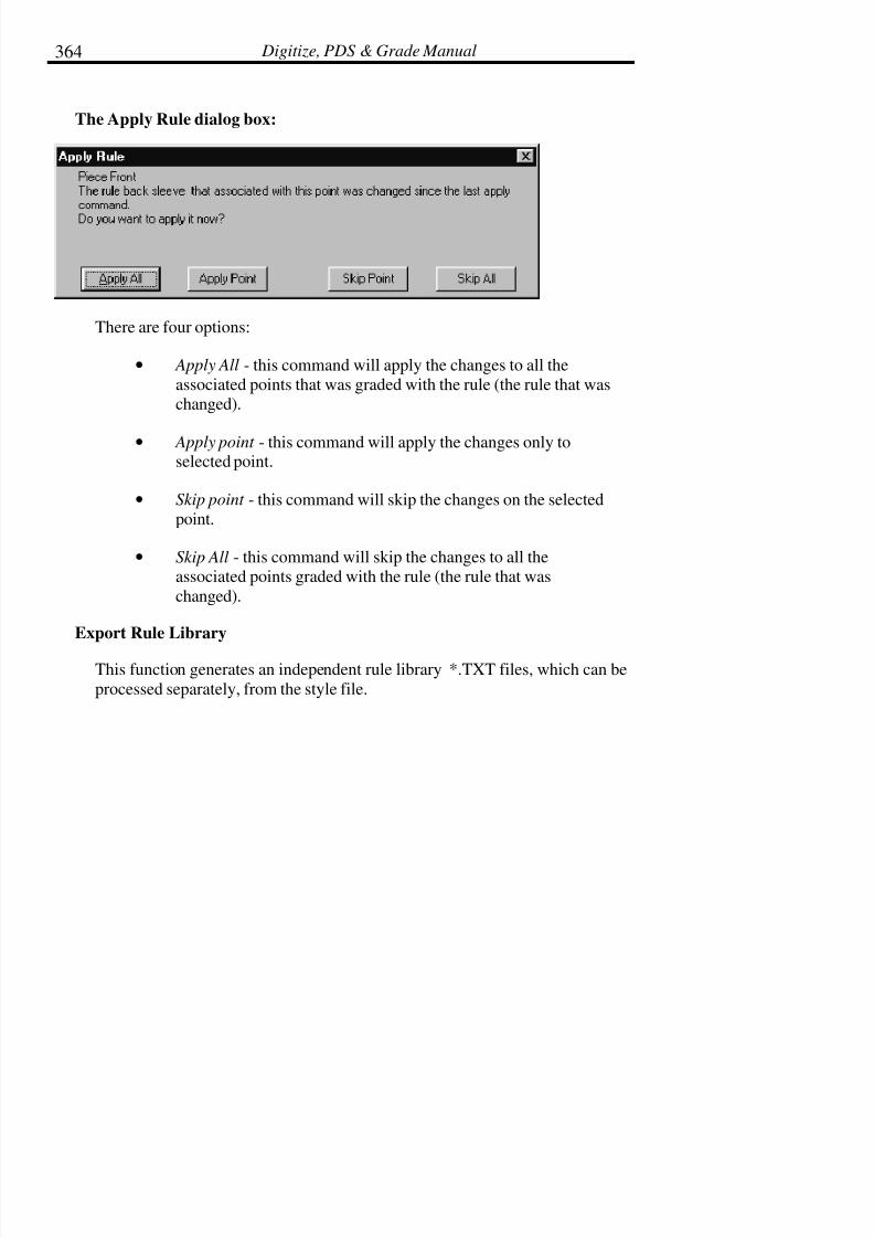
7/28/2019 OptiTex PDS User Manual
http://slidepdf.com/reader/full/optitex-pds-user-manual 386/727
Digitize, PDS & Grade Manual364
The Apply Rule dialog box:
There are four options:
• Apply All - this command will apply the changes to all theassociated points that was graded with the rule (the rule that waschanged).
• Apply point - this command will apply the changes only toselected point.
• Skip point - this command will skip the changes on the selectedpoint.
• Skip All - this command will skip the changes to all theassociated points graded with the rule (the rule that was
changed).
Export Rule Library
This function generates an independent rule library *.TXT files, which can be
processed separately, from the style file.

7/28/2019 OptiTex PDS User Manual
http://slidepdf.com/reader/full/optitex-pds-user-manual 387/727
Chapter 6: Grading Menu 365
Sort Library:
Sort library by name
This sort function arranges rule library by name in increasing alphabetical
order.
Sort library by dx
This sort function arranges rule library by dx vales in increasing order.
Sort library by dy
This sort function arranges rule library by dy vales in increasing order.
Export Library to Excel
The rule library can be converted to excel file and can be mailed and reportedby using this dialog box.
Use the Excel file path to define or crate the report file.
The file can be set visible and it will be open after saving the file.
Check the “Append to existing file” box in order to save the rule library at the
end of existing file.
Mail Report - to mail the Excel file check the Mail Report box.
Import Library from Excel
To open a library rule from excel select the excel file from the disk by using
the; “browse” button to browse yours files.

7/28/2019 OptiTex PDS User Manual
http://slidepdf.com/reader/full/optitex-pds-user-manual 388/727
Digitize, PDS & Grade Manual366
Grade Rule Library
The existing libraries in PDS are to demonstrate the use of existing gradingrule libraries. They are only a suggestion for basic grading of pattern design.
The grading is based on standard grading methods. When using the existing
grade rule library, there are some important details to observe:
• The working units are inches.
• The rule names are per point and can be found in standardgrading books.
• When grading a pattern the baseline should always be parallel tothe horizontal direction.
• The start point is always the pattern’s bottom left corner and the
working direction is always in a clockwise manner.
• Position the piece with the center front or back line facing thebottom of the screen.
12
3
45
6
7
8
910
11 12
• When locating the grading rule named “crotch 1 & 2”, note therule is followed by a number. The number indicates that are two
rules existing for the Dart and the rule should be applied to the
points in a clockwise manner.

7/28/2019 OptiTex PDS User Manual
http://slidepdf.com/reader/full/optitex-pds-user-manual 389/727
Chapter 6: Grading Menu 367
Grading using the rule library examples:
• Open a design file from C:\Texwrk\Examples.
• From the View menu check Grading Library. (Click the rightmouse button on the Grading Library and uncheck the
‘dockable’ option to allow the window to be moved).
• Click the right mouse button on the Grading Library and select
the Open Rule Library.
• When the Open Grading Rules Library Dialog is displayed, selectthe desired grading style. Click Open. The rule library sizes arenow available.

7/28/2019 OptiTex PDS User Manual
http://slidepdf.com/reader/full/optitex-pds-user-manual 390/727
Digitize, PDS & Grade Manual368
! Note: If the design file has defined sizes, these will be replaced by the sizes
in the rule library.
• From the Grading Menu, select Load Sizes.
• By using the drop down menu in the Grading Library, select thename of the rule to apply to the currently selected point. (Forexample: The lowest grading point in pants side seam is called
“hem+side seam” and the lowest grading point in pants inside
seam is called “hem+inseam”).
• Apply the grading rule to the point by clicking the Apply Ruleicon
Or from the Grading Menu select Apply Rule.

7/28/2019 OptiTex PDS User Manual
http://slidepdf.com/reader/full/optitex-pds-user-manual 391/727
Chapter 6: Grading Menu 369
• Repeat step #6 and #7 until the whole pattern is graded.

7/28/2019 OptiTex PDS User Manual
http://slidepdf.com/reader/full/optitex-pds-user-manual 392/727
Chapter 7: Pleats Menu 371
Chapter 7: Pleats Menu
The Pleats menu replaces the Axis sub-menu that was previously in the Editmenu (Add, Add by Angle, and Remove). Axis lines are now called Pleat
lines. The Pleat Attribute dialog box will display by double clicking on a
pleat line.
Add Pleat Lines
• Click and drag from the point where the pleat line will start tothe point where the pleat line will end.
• From the PLEAT menu choose ADD PLEAT LINE.
• A dotted line displays stretching from the first selected point tothe last selected point. The lines are displayed for all sizes.
Add Pleat By Angle
Use Add Pleat By Angle to insert a dashed line (a pleat, fold or a guideline)
between any two points as long as it is inside the piece’s perimeter. Thedirection of the angle is determined from a counter clockwise position starting
at zero (0) to the right side of the current point. It stretches from the selected
point to meet the piece’s perimeter at the angle defined in the dialog box. Anew point is created at that point. If multiple points are selected, multiple lines

7/28/2019 OptiTex PDS User Manual
http://slidepdf.com/reader/full/optitex-pds-user-manual 393/727
Digitize, PDS & Grade Manual372
are made, all defined by the same angle. These lines can be used as “Help
Lines” for final construction of the pattern.
Remove Pleat Lines
The Remove Pleat Lines command removes Pleat lines from a piece. PleatLines are created when a Pleat is made with the Pleat tool or by using the Add
Pleat Lines command.
To Remove Pleat Lines:
• In order o remove points from he Pleat Line, Select the pointsand drag them out of the working area.
• From the PLEAT menu choose REMOVE PLEAT LINES.
• All Pleat Lines between the selected points will be removed.
! Note: All Pleat Lines between the two selected points will be removed. To
remove just one of the Pleat Lines, select the first point, then press
and hold the Shift key while selecting the second point. Only those
two points will be grouped, and only that Pleat Line will be removed
Create Box or Knife
This command adds a box or a knife pleat from the Pleats menu.
• Click and drag from the point where the pleat will start to the
point where the pleat will end.
• From the Pleats Menu select Create Box or Knife. The PleatAttribute dialog box will display.
• Enter the desired pleat information.
7/28/2019 OptiTex PDS User Manual
http://slidepdf.com/reader/full/optitex-pds-user-manual 394/727
Chapter 8: Darts Menu 373
Chapter 8: Darts Menu
A Darts menu is available with numerous new dart commands.
Open DartThe Open Dart command is a combination of two commands: Add Fullness
and Dart.
• Select the point where the fullness will start (the point where theslashing will begin).
• From the Darts menu, select Open Dart.
• The Values to Open dialog box now displays. Enter the amountof fullness to add.
• Click OK.
• The Dart Attributes dialog box now displays. The two pointsthat resulted from the added fullness are the two points marking
the dart legs.
• Enter the desired dart information.
• Click OK.
Open Multiple Darts
The Open Multiple Darts command creates several darts on a selected segment
at the same time.

7/28/2019 OptiTex PDS User Manual
http://slidepdf.com/reader/full/optitex-pds-user-manual 395/727
Digitize, PDS & Grade Manual374
• Click and drag to the points on a segment where the darts are tobe created.
• From the Darts menu select Open Multiple Darts.
• The Open MultiDart dialog box will display.
• Enter the desired multiple dart information and click OK.
• The darts will be created on the first and last selected points. If more than 2 darts are created, they will be equally distributed
between the points.
Create Dart
The Create Dart command creates a dart.
7/28/2019 OptiTex PDS User Manual
http://slidepdf.com/reader/full/optitex-pds-user-manual 396/727
Chapter 8: Darts Menu 375
• Click and drag to select the first and last points of the dart legs(the points must already be on the line).
• From the Darts menu, select Create Dart.
• When the Darts Attributes dialog box appears, select the desiredinformation.
• Click OK.
Edit Dart
The Edit Dart command opens the Dart Attributes dialog box of a selected dart
by double clicking on the dart apex.
Close Darts
The Close Darts command closes the selected dart(s).
• Select the apex of the dart to close.
• From the Darts menu select Close Darts. The pattern will adjustas if the dart was physically closed.
• To reopen the dart, select the Undo tool.
Remove Darts
The Remove Darts command deletes the selected dart(s).
Copy Darts
The Copy Darts command copies an existing dart and pastes it in different
location.
7/28/2019 OptiTex PDS User Manual
http://slidepdf.com/reader/full/optitex-pds-user-manual 397/727
Digitize, PDS & Grade Manual376
• Select the dart by clicking on its apex.
• From the Darts menu select Copy Darts.
• Select the point, which will become the middle point (theoverlap extension), between the dart leg points.
• From the Darts menu select Paste Darts.
Paste Darts
The Paste Darts command pastes the copied darts to a select point.
Rotate Dart to Point
The Rotate Dart to Point command pivots the dart to a new location.
• Select the dart by clicking on its apex.
• From the Darts menu select Rotate Dart to Point. The cursorwill become the dart tool and will attach to the dart apex.
• Drag the cursor (dart tool) to the new location along theperimeter of the pattern piece where the dart is to be moved.
Click on the point.
• Select a point on the piece to pivot around the dart apex.
•Pivot to the desired location and click the mouse.
• A Move Dart dialog box will appear listing the percentage anddistance of the dart that has moved.
• Click OK or enter in the desired percentage/distance.

7/28/2019 OptiTex PDS User Manual
http://slidepdf.com/reader/full/optitex-pds-user-manual 398/727
Chapter 8: Darts Menu 377
Rotate Around Center
The Rotate Around Center command is similar to the Rotate Dart to Pointcommand except the dart can be rotated on another point rather than the apex.
•
Select the dart by clicking on its apex.
• From the Darts menu select Rotate Around Center.
• Select the point of rotation (rather than the dart apex) along thedart line, the line through the dart center above or below the dart
apex.
• A dialog box will appear listing the distance from the dart apex
to the specified point of rotation. Click OK or enter in thedesired distance.
• Select a point on the piece to pivot around the point of rotation.
• Pivot to the desired location and click the mouse.
• A Move Dart dialog box will appear listing the percentage anddistance of the dart that has moved.
• Click OK or enter in the desired percentage/distance.
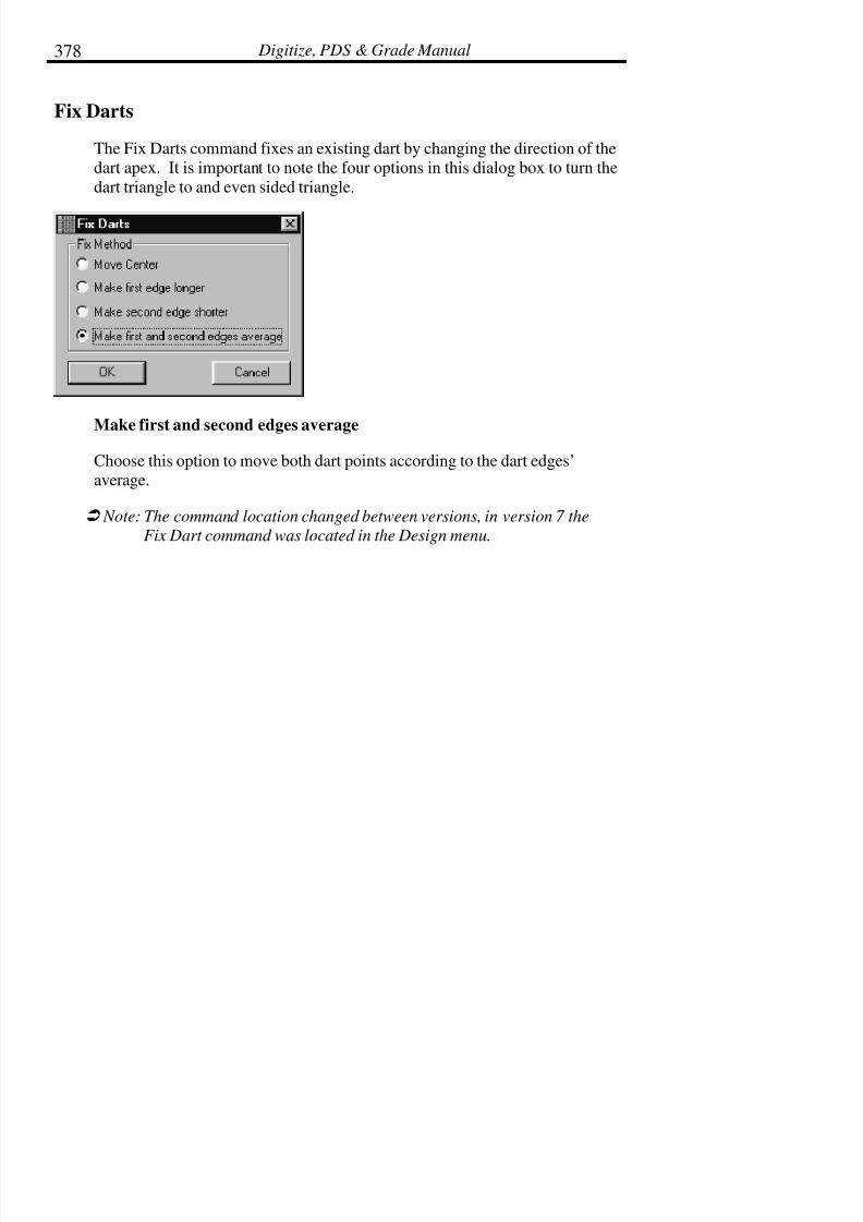
7/28/2019 OptiTex PDS User Manual
http://slidepdf.com/reader/full/optitex-pds-user-manual 399/727
Digitize, PDS & Grade Manual378
Fix Darts
The Fix Darts command fixes an existing dart by changing the direction of thedart apex. It is important to note the four options in this dialog box to turn the
dart triangle to and even sided triangle.
Make first and second edges average
Choose this option to move both dart points according to the dart edges’average.
! Note: The command location changed between versions, in version 7 the
Fix Dart command was located in the Design menu.
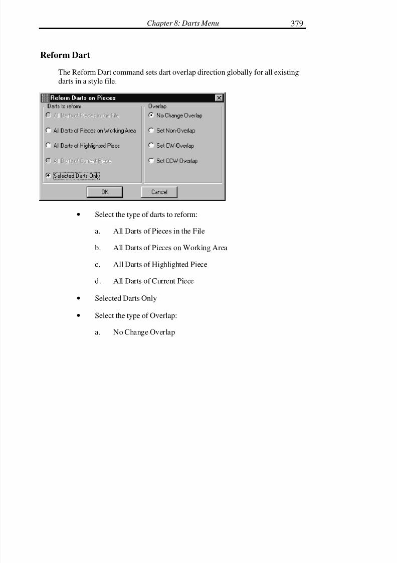
7/28/2019 OptiTex PDS User Manual
http://slidepdf.com/reader/full/optitex-pds-user-manual 400/727
Chapter 8: Darts Menu 379
Reform Dart
The Reform Dart command sets dart overlap direction globally for all existing
darts in a style file.
• Select the type of darts to reform:
a. All Darts of Pieces in the File
b. All Darts of Pieces on Working Area
c. All Darts of Highlighted Piece
d. All Darts of Current Piece
• Selected Darts Only
• Select the type of Overlap:
a. No Change Overlap

7/28/2019 OptiTex PDS User Manual
http://slidepdf.com/reader/full/optitex-pds-user-manual 401/727
Digitize, PDS & Grade Manual380
b. Set Non-Overlap
c. Set CW-Overlap (Clockwise)
d. Set CCW-Overlap (Counter-Clockwise)
• Click OK.

7/28/2019 OptiTex PDS User Manual
http://slidepdf.com/reader/full/optitex-pds-user-manual 402/727
Chapter 9: Design Menu 381
Chapter 9: Design Menu
The Design menu contains advanced design commands used to build and edit
patterns directly on the screen. Draft a closed perimeter piece on screen, edit
the existing piece, or use parts of other pieces to easily and efficiently createnew pattern pieces.
Create Parallel
Create Parallel is used to create a parallel segment from a selected section
along a piece’s perimeter. Create Parallel allows the user to define the widthor length of the segment as well as decide if the segment should extend to the
piece’s perimeter. When the end points touch the perimeter, the Internal Cut
tool may be used to split the piece along the new parallel line.
To Create a Parallel Segment from an Existing Section:
• Click and drag the arrow in a clockwise direction to select thedesired end points on segment to Parallel.
• From the DESIGN menu choose CREATE PARALLEL.
• Enter the values for the width or length of the parallel segmentin the Create Parallel To Segment dialog box. The system allows
the user to extend first and last point of new line by checkingthis option.

7/28/2019 OptiTex PDS User Manual
http://slidepdf.com/reader/full/optitex-pds-user-manual 403/727
Digitize, PDS & Grade Manual382
• Grades the new segment using the existing grading of theparallel segment.
! Tip: Enter a positive number to create an internal parallel line, enter a
negative number to create an external parallel line.
• Click OK
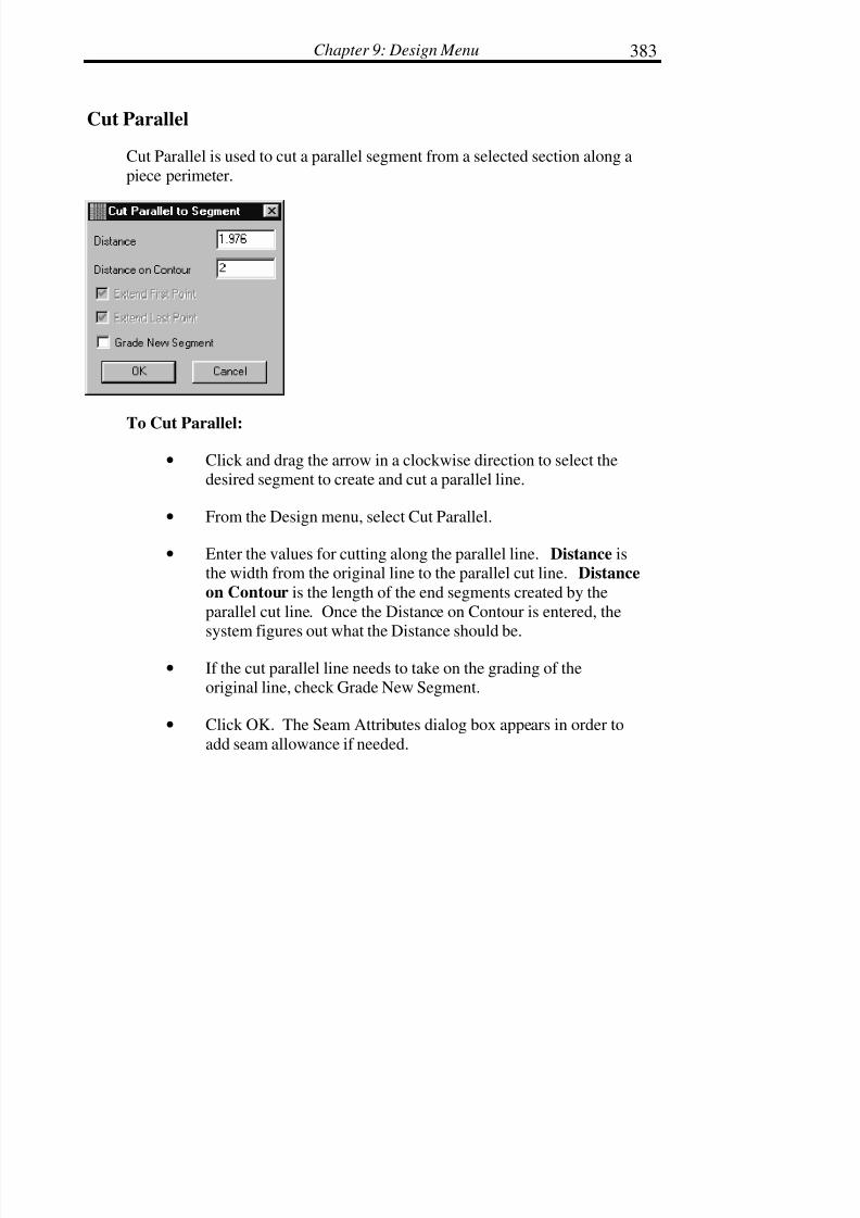
7/28/2019 OptiTex PDS User Manual
http://slidepdf.com/reader/full/optitex-pds-user-manual 404/727
Chapter 9: Design Menu 383
Cut Parallel
Cut Parallel is used to cut a parallel segment from a selected section along a
piece perimeter.
To Cut Parallel:
• Click and drag the arrow in a clockwise direction to select thedesired segment to create and cut a parallel line.
• From the Design menu, select Cut Parallel.
• Enter the values for cutting along the parallel line. Distance isthe width from the original line to the parallel cut line. Distance
on Contour is the length of the end segments created by the
parallel cut line. Once the Distance on Contour is entered, thesystem figures out what the Distance should be.
• If the cut parallel line needs to take on the grading of theoriginal line, check Grade New Segment.
• Click OK. The Seam Attributes dialog box appears in order to
add seam allowance if needed.

7/28/2019 OptiTex PDS User Manual
http://slidepdf.com/reader/full/optitex-pds-user-manual 405/727
Digitize, PDS & Grade Manual384
Segment Length
Segment length shows the length of any selected segment. This feature alsoallows for alteration of the segment’s length.

7/28/2019 OptiTex PDS User Manual
http://slidepdf.com/reader/full/optitex-pds-user-manual 406/727
Chapter 9: Design Menu 385
Copy/Paste
Choose copy/paste button to paste or copy length values from one segment to
anther segment.
Copy/paste button has three options:
• Copy - choose this option when you want to copy the lengthvalues from the segment length dialog box.
• Paste Length - choose this option when you want to paste thevalues of the copied segment to a required segment. You canpaste either value that was copied in the segment length dialog
or in the compare length dialog.
• Paste Delta - choose this option when you want to paste onlythe delta between the sizes from the origin segment to the
selected segment and not the segment value (you can use thisoption only when the “Base size only” box is enable and check).
Base size only box
This command gives you the option to control each size length separately andalso paste all the copied sizes length (from “Compare Length” table) to the
selected segment. The “Extend By” box in this table allows the user to decide
if copied line should be extended or not to meet existing lines of a patternpiece.
Refresh
Choose this option when you want to return to the original sizes.
Length
Length displays the length of the selected segment.

7/28/2019 OptiTex PDS User Manual
http://slidepdf.com/reader/full/optitex-pds-user-manual 407/727
Digitize, PDS & Grade Manual386
Extend by
Extend by provides the opportunity to change the segment’s length.
Curve
The curve option extends or shortens the segment’s length by adjusting thecurve of the segment.
First Horizontal
This option extends or shortens the segment’s length by adjusting the first
point of the segment in the horizontal or X direction.
Last Horizontal
This option extends or shortens the segment’s length by adjusting the last point
of the segment in the horizontal or X direction.
First Vertical
This option extends or shortens the segment’s length by adjusting the first
point of the segment in the vertical or Y direction.
Last Vertical
This option extends or shortens the segment’s length by adjusting the last pointof the segment in the vertical or Y direction.
First Diagonal
This option extends or shortens the segment’s length by adjusting the firstpoint of the segment in the diagonal or X and Y direction.

7/28/2019 OptiTex PDS User Manual
http://slidepdf.com/reader/full/optitex-pds-user-manual 408/727
Chapter 9: Design Menu 387
Last Diagonal
This option extends or shortens the segment’s length by adjusting the last point
of the segment in the diagonal or X and Y direction.
Hole to Piece / Piece to Hole
This command creates a new pattern from internal/external lines (that can be
draw on a pattern or cut) on a separate piece. The new piece is displayed in thePiece Display bar.
! Note: Internal/external line needs to be selected before using this option
from the Design menu.
Convert Hole to Piece
Converting a Hole to a Piece:
• Select the internal/external line from which a new piece will becreated.
•From the Design menu choose Hole to Piece.
Convert Piece to Hole
The Piece to Hole command changes a pattern placed on a larger pattern to an
internal/external line (that can be draw or cut) in the larger pattern. Thesmaller piece becomes an internal/external line on the larger piece and is
7/28/2019 OptiTex PDS User Manual
http://slidepdf.com/reader/full/optitex-pds-user-manual 409/727
Digitize, PDS & Grade Manual388
removed for the piece bar. The smaller piece is removed from the Piece
Display Bar.
Converting a Piece to a Hole:
• Select the piece to transform into a hole and place it at thecorrect position on the larger piece.
• From the Design menu choose Piece to Hole.
Copy Hole to Piece
The Copy Hole to Piece command will create a new pattern from
internal/external lines (that can be draw on a pattern or cut) on a separate piece
and the hole will stay on the piece. The new piece ( a copy of the hole ) isdisplayed in the Piece Display bar.
Copy Piece to Hole
The Copy Piece to Hole command changes a pattern placed on a larger pattern
to an internal/external line (that can be draw or cut) in the larger pattern. The
smaller piece becomes an internal/external line on the larger piece and a copyof the new piece gets added to the piece bar.
Point Connection
Create Point Connection creates a connection between internal point andexternal contour.
! Note: You can choose that any drafted internal point will be connected by
default to the external contour if there is a snap between the point
and the external segment/contour. Use “Draft Setup” dialog box to
set default properties to a connected point under “Option” menu.
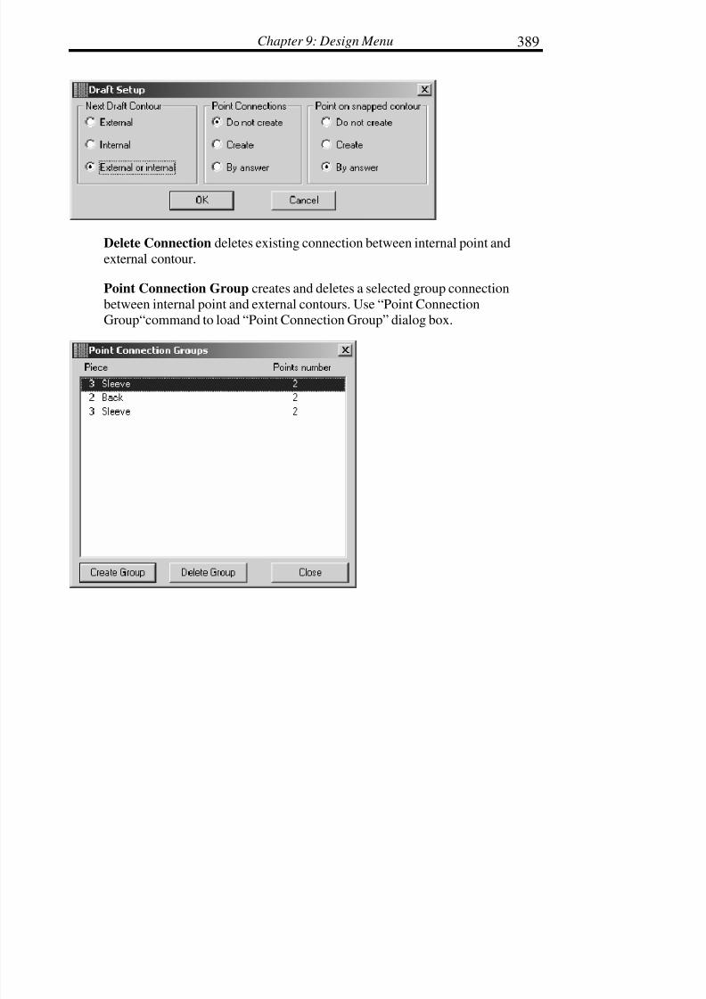
7/28/2019 OptiTex PDS User Manual
http://slidepdf.com/reader/full/optitex-pds-user-manual 410/727
Chapter 9: Design Menu 389
Delete Connection deletes existing connection between internal point and
external contour.
Point Connection Group creates and deletes a selected group connection
between internal point and external contours. Use “Point ConnectionGroup“command to load “Point Connection Group” dialog box.

7/28/2019 OptiTex PDS User Manual
http://slidepdf.com/reader/full/optitex-pds-user-manual 411/727
Digitize, PDS & Grade Manual390
! Note: Point Connection Group dialog box is a “modulous” dialog box!
This means that you can work on the working area while the dialog
is open.
Equal Segments
This command has three options: Definition, Options and Show with Color.
The Equal Segments command creates equal segment groups. After the user
identifies a group of segments, any change made on one of the group members
(adding notches, changing segment length etc.) will automatically update theother groups members according to the group’s relationship.
Equal segment groups modes: “Length only” and “Proportional”.
Definition
7/28/2019 OptiTex PDS User Manual
http://slidepdf.com/reader/full/optitex-pds-user-manual 412/727
Chapter 9: Design Menu 391
Group Names
The entire equal segments groups in the file listed below and the number of
segments in each group.
Set Color
Set the segments color here. All segments in the same group displayed on the
working area in the same color. Select the color and click the set button.
New Group
Use the name field to give the group name. Click the Create Group button to
create the group
Length Only
Check this box in order that the segment in the group will be equal only by thelength
Proportional
Check this box in order that the any length change on one of the segment willaffect the other member at the group by changing the length proportionally to
the original
segment.
Delete Group
Click on the button in order to delete the highlight group

7/28/2019 OptiTex PDS User Manual
http://slidepdf.com/reader/full/optitex-pds-user-manual 413/727
Digitize, PDS & Grade Manual392
Segment
Use the arrows to chose between the segment in the group in order to apply
changes to one of them.
Add New Segment
Click to add a new segment to a group. Select the segment and then highlight
the group to be adds to.
Options
These options will set the default for all the equal segment groups.
Create Equals by Cut:
Segments, Length only or None
Create equals by Mirror
Custom Fit
The Custom Fit system, should give the user the right tools to be able to take
almost any kind of garment, to create a set of parameters, that by definition, if
these parameters will be changed, the specific garment will fit any customermeasurements.
7/28/2019 OptiTex PDS User Manual
http://slidepdf.com/reader/full/optitex-pds-user-manual 414/727
Chapter 9: Design Menu 393
Horizontal Fit
Constrain a point to horizontal movement only.
After define the stable line, the pattern growth will occur from this axis and
beyond.
(For example: define the center front as a fixed line).
• Select with the cursor a require segment.
• From the Design menu choose Custom Fit >Horizontal Fitoption.
A colored Dash line will appear on the selected section.
Vertical fit
Constrain a point to Vertical movement only.
After define the stable line, the pattern growth will occur from this axis andbeyond.
(For example: define the center front as a fixed line).
• Select with the cursor a require segment.
• From the Design menu choose Custom Fit >Horizontal Fitoption.
A colored Dash line will appear on the selected section.
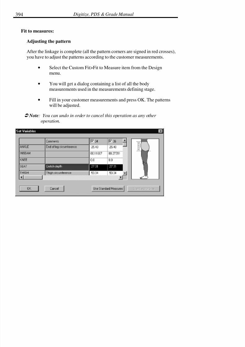
7/28/2019 OptiTex PDS User Manual
http://slidepdf.com/reader/full/optitex-pds-user-manual 415/727
Digitize, PDS & Grade Manual394
Fit to measures:
Adjusting the pattern
After the linkage is complete (all the pattern corners are signed in red crosses),
you have to adjust the patterns according to the customer measurements.
• Select the Custom Fit>Fit to Measure item from the Designmenu.
• You will get a dialog containing a list of all the bodymeasurements used in the measurements defining stage.
• Fill in your customer measurements and press OK. The patternswill be adjusted.
! Note: You can undo in order to cancel this operation as any other
operation.

7/28/2019 OptiTex PDS User Manual
http://slidepdf.com/reader/full/optitex-pds-user-manual 416/727
Chapter 9: Design Menu 395
Checking the results
Sometimes, in order to check that the Fit to Measure comes up with the
correct results, you want to see the old patterns and the adjusted one nested. Itcan be done using custom fit in the following way:
• After you finish the measurements defining stage (with theAdvanced tool), Open the Sizes dialog from the Grading menu.
Define two sizes, in your style file. Assign the names A and B.
• Open the Fit to Measure dialog. You will see two columns; onenamed A, the second named B. these are the two sizes. The
checkbox besides the names indicates if the Fit to Measure isgoing to be applied to the size.
Only for the checking, uncheck A (you do not want to adjust this size, it will
be used as a reference) and check B (this is the size you are going to Fit to
Measure).
• Fill in the B column the customer body measurements and pressOK.
• Now size A is the original pattern and size B is the adjusted onesand you see them as a nest
! Note: The stack point of the two sizes is point no.1 of the patterns. You
can change it using the Stack Point command from the Gradingmenu.
You can also define more than two sizes and use the 1st one as a reference and
the rest as body measurements of some customers.
Grading using custom fit

7/28/2019 OptiTex PDS User Manual
http://slidepdf.com/reader/full/optitex-pds-user-manual 417/727
Digitize, PDS & Grade Manual396
By defining a few sizes in the style file and using Fit to Measure on all of
them you can perform grading (by exact body measurements) of your patterns.
Standard measures
Use standard measures for getting the different values and sizes names for the
same body measures according to the different countries.
! Note: You can create your own tables for the countries or customer in
Measures setup table from Design menu.
Measures setup
In this table you are able to add your own parameters.
To change or add values:
•
Click on the Edit button.
• Choose the required group to change.
• Add or change the option in the opened dialog box.
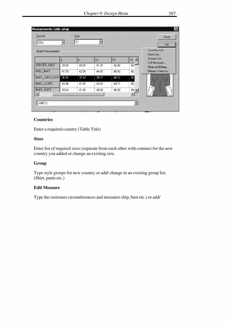
7/28/2019 OptiTex PDS User Manual
http://slidepdf.com/reader/full/optitex-pds-user-manual 418/727
Chapter 9: Design Menu 397
Countries
Enter a required country (Table Title)
Sizes
Enter list of required sizes (separate from each other with comma) for the new
country you added or change an existing size.
Group
Type style groups for new country or add/ change in an existing group list.
(Shirt, pants etc.)
Edit Measure
Type the customer circumferences and measures (hip, bust etc.) or add/

7/28/2019 OptiTex PDS User Manual
http://slidepdf.com/reader/full/optitex-pds-user-manual 419/727
Digitize, PDS & Grade Manual398
Changes in existing edits measure list.
Measure Bitmap
Create .BMP file to add to a specific measure (The picture will show
In the box whenever a measure is selected).
Bitmap Directory
Create your own bitmap directories from the .BMP files.
Custom fit tools
The Advanced Toolbar consists of tools used for Advanced Features in PDS,
specifically, the Custom Fit Feature and the Fabric Feature.
With the advanced tools (vertical, horizontal, curve) you can teach the systemhow to Custom Fit a pattern.
Adding rules, which specify the wanted distances (vertical/horizontal) between
pair of points and the wanted length of the curves, can do it. This can be doneusing the 4
Customs Fit tools which appear in the advanced toolbar.
When you are done to define a segment, you will see that the two points havea small yellow balloon beside them with lines inside. The two lines have the
same color. This is an indication that the vertical or horizontal distance
between the two points is set. When the process continues you will see thatmore balloons are added to more points each of them contains line with a
color. The distance between pair of points, which has horizontal lines with the
same color, is set. The distance between pair of points, which has horizontallines with different colors, is not set. This means that the system cannot figure

7/28/2019 OptiTex PDS User Manual
http://slidepdf.com/reader/full/optitex-pds-user-manual 420/727
Chapter 9: Design Menu 399
this distance out of the rules specified and therefore more rules must be
specified before proceeding to the next stage.
The pattern is ready for set variables if all the corner balloons signed with redcrosses.
Otherwise, you have to define more vertical or horizontal rules between anyblue and red point.
Once you add such a rule all the blue and red points will get the same color
and you will know that the linkage is complete and the pattern is ready for
Fit to measures stage:
Vertical Measurement Tool
The vertical tool is used to fix the vertical measurement between pair of points
to a specific distance. The distance can be set to any expression made of
numbers and body measurements, for example, an expression can be:BACK_SHOULDER/2+1 and means that the distance is a half of the shoulder
to shoulder body measurement plus one inch. The points must belong to the
same pattern and can only be points of the external
Contour (the current version supports custom fitting of external contour only,
future versions will support internals as well).
• Select the vertical tool, click on the 1st point, click on the 2ndpoint (one by one, the order is not important).
• Drag the mouse to the place you want the rule to appear in andclick again. An Edit Dimension dialog will open.
7/28/2019 OptiTex PDS User Manual
http://slidepdf.com/reader/full/optitex-pds-user-manual 421/727
Digitize, PDS & Grade Manual400
• In the Expression field of this dialog, enter the requiredExpression.
• After you have added your expression, press OK. The new rulewill appear on the screen.
• You can also take the vertical rule tool and add a new rulebetween points which sets the vertical distance between them to0.0 as they should align (pay attention that we set the vertical
distance to 0.0 and not the horizontal distance).
You can also take the vertical rule tool and add a new rule between points
which sets the vertical distance between them to 0.0 as they should align (pay
attention that we set the vertical distance to 0.0 and not the horizontaldistance).
Expression
You can use any of the predefined measurements listed below by typing their
names or double clicking on any of them as part of your expression. The
predefined measurements are divided into groups. You can select
measurements from any of the groups. Use the bottom combo box in order toselect your required group.
! Note: If the body measurement you are looking for does not exist, you can
put in your own name, any name will do. You can also refer to the
Measurement Setup chapter to see how to add your own name with
your own pictures to the body Measurement list.
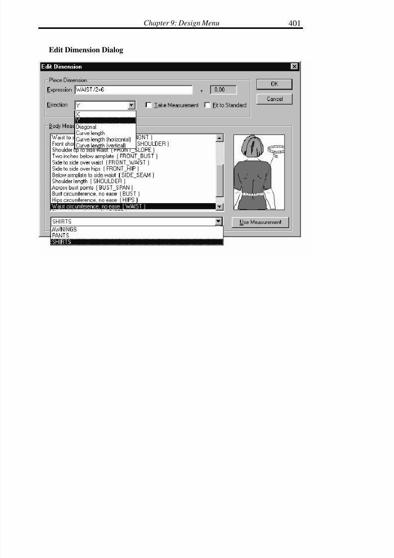
7/28/2019 OptiTex PDS User Manual
http://slidepdf.com/reader/full/optitex-pds-user-manual 422/727
Chapter 9: Design Menu 401
Edit Dimension Dialog

7/28/2019 OptiTex PDS User Manual
http://slidepdf.com/reader/full/optitex-pds-user-manual 423/727
Digitize, PDS & Grade Manual402
Taking a measurement
When you want to make sure that the distance between pair of points is the
same as the distance between another pair. The system fits one pattern to the
customer measurements and than takes a measurement from this pattern and
uses it for the fitting of another pattern. (A good example for this kind isArmhole and sleeve cap).
• Use the relevant (horizontal/vertical/curve) tool in order tospecify the distance or the curve length you would like to take
its measurement.
• When the Edit Dimension dialog is opened, specify in theExpression field the name you would like to give themeasurement (Any name).
•
Check the Take Measurement box. It will assure that thismeasurement is being taken and not given.
• Once you press OK you will see that the rule appears in <>brackets (<NAME>) which tell that the measurement is being
taken.
• Choose one of the Direction options to determine the
increase/decrease direction of the defined curve.
• By giving another segment the same Expression name andchecking the ‘Use Measurements’ box they will have the same
segment length.

7/28/2019 OptiTex PDS User Manual
http://slidepdf.com/reader/full/optitex-pds-user-manual 424/727
Chapter 9: Design Menu 403
Horizontal Measurement Tool
The Horizontal tool is used to fix the Horizontal measurement between pair of
points to a specific distance. The distance can be set to any expression made of
numbers and body measurements, for example, an expression can be:Side_Seam+1 and means that the distance is the side-seam body measurement
plus one inch. The points must belong to the same pattern and can only be
points of the external contour (the current version supports custom fitting of
external contour only, future versions will support internals as well).
• Select the Horizontal tool, click on the 1st point, click on the2nd point (one by one, the order is not important,).
• Drag the mouse to the place you want the rule to appear in and
click again. An Edit Dimension dialog will open.
• In the Expression field of this dialog, enter the requiredExpression.
• After you have added your expression, press OK. The new rulewill appear on the screen.
• You can also take the Horizontal rule tool and add a new rulebetween points which sets the vertical distance between them to
0.0 as they should align (pay attention that we set the Horizontal
distance to 0.0 and not the vertical distance).
Hide/Show measures
When too many measurement rules are created, and it becomes difficult to see
the patterns behind, use the measures item in the Display menu>Display
Piece Attributes in order to hide or show the measures.

7/28/2019 OptiTex PDS User Manual
http://slidepdf.com/reader/full/optitex-pds-user-manual 425/727
Digitize, PDS & Grade Manual404
! Note: when the measures are not shown, the 4 measurement tools are not
available.
Edit/Delete a measures
In order to edit a measurement
• Select the relevant pattern with the cursor.
• Click exactly on the middle of the measurement text.
• In the opened Edit Dimension dialog Alter the required valuesand press OK.
In order to delete a measurement, select it in the same way and either select
Delete from the Edit menu or press the DEL button on the keyboard.
The distance of an existing measurement can be edited with the Move Internaltool:
• Select the Move Internal tool.
• Click once on an existing measurement to move it.
• Click twice on an existing measurement to edit it with the EditDimension dialog box.
Curve length
Choose one of the Direction options to determine the increase/decreasedirection of the defined curve.
Use Measurements
After checking the Take Measurements box for a required

7/28/2019 OptiTex PDS User Manual
http://slidepdf.com/reader/full/optitex-pds-user-manual 426/727
Chapter 9: Design Menu 405
Segment, by giving the target segment the same Expression name and
checking the ‘Use Measurements’ box they will have the same segmentlength.
Measurements Names
Use the measurements names directory to define your measurements (usethe bitmap measurements to understand the meaning of a specific
measurements).
Pattern Group
Choose pattern group according to your pattern type! When you are taking
measurements from a shirt, choose the shirts group to reach specificmeasurements for shirts.
Industrial Fabrics
Create by Measure
Measure Tool General description
Pivot points: Two reference Pivot points. All measures are taken from thesepoints.
Pivot Line: A line that runs between the two pivot points. The two pivot points
are marked as AA and BB
Measure Point: A measure that is part of the (pool) measured contour
(Internal or External).
Measure Values: For each measure point you should input two values. One
from AA to the measured point and one from BB.

7/28/2019 OptiTex PDS User Manual
http://slidepdf.com/reader/full/optitex-pds-user-manual 427/727
Digitize, PDS & Grade Manual406
Curve indicator: Each Measure Point is Either a Line point or Curve Point.
Choose the right attribute for each point.
! !! ! Note: Since most pools have more curved edges then sharp edges, the
default of this field is curved.
Using the measure Tool
• Define a line with two-pivot point. The pivot points must be
outside the measured object area and both from the same side.
Ensure that the pivot line will not intersect the measured object.

7/28/2019 OptiTex PDS User Manual
http://slidepdf.com/reader/full/optitex-pds-user-manual 428/727
Chapter 9: Design Menu 407
Wrong pivot selection. Good pivot Selection
Enter the distance between the two Pivot points in the upper input fields.
• From each measure point measure the AA distance and the BBdistance and set on off the curved field as needed. Keep the
points input order in clockwise direction.
The Measure values must be positive and the Distance between the pivot pointcan’t be Zero.
The result of this measure will be the follow element:

7/28/2019 OptiTex PDS User Manual
http://slidepdf.com/reader/full/optitex-pds-user-manual 429/727
Digitize, PDS & Grade Manual408
(0,0) - The pivot Point and Pivot Line are part of the shape - (4,0)
After finishing to input the measure values press OK.
OptiTex Poll solution will calculate the contour.
The measured contour should always be above the Pivot line.
The pivot line will display as the base line, with an arrow.
Hole By measure
An Internal Hole (Contour)
If your pool is built of few elements specially an internal hole, You are able to
input the points of the hole, by using the option: ‘Hole by Measure’ which is
under the Design menu and the Industrial Fabric command. The internalcontour or contours, you can input few internal contours, one by one, can be
set only after you have calculated the external contour.
• Calculate the external contour.
• Click the external contour with the left mouse button.

7/28/2019 OptiTex PDS User Manual
http://slidepdf.com/reader/full/optitex-pds-user-manual 430/727
Chapter 9: Design Menu 409
• Choose the menu option ‘Hole by Measure’.
• The same input dialog box appears. Start to input the values of the internal contour.
! Note: You are using the same reference Pivot line for internal and
externals.
You can use external contours that were created by another CAD software. In
that case there is NO Pivot Points. You should click the external contour,
choose the ‘Hole by Measure’ and input the Pivot Points.
The pivot must be entered, but the internal contour might shift in relation to
the external contour. Any internal contour is related as hole inside themeasured element during the cutting process.

7/28/2019 OptiTex PDS User Manual
http://slidepdf.com/reader/full/optitex-pds-user-manual 431/727
Digitize, PDS & Grade Manual410
Create Parallel Cutting
The stripe cutting command is based on a user define information. The
information includes: The first cut, from the out most left point of the external
contour. Distance between each cut line.
Seam value, if any.
The cut lines are Vertical. If you wish to make them in another direction, you
can rotate the piece according the required angle.
• There is a minimum slice value that is very small, like 5 screenpixels.
• The details that was entered will be saved as defaults values for
the next time the parallel cut lines window will be opened.
• In the end of the cutting process the original element will besplit. Internal Contours will treat as hole.
The Cut elements will be divided to the followed element.

7/28/2019 OptiTex PDS User Manual
http://slidepdf.com/reader/full/optitex-pds-user-manual 432/727
Chapter 9: Design Menu 411
Scatter Pieces
The Scatter Piece command arranges pieces for plotting according to their
Quantities/Set and Orientation. It recognizes pieces with more than one
copy. There are four modes to the Scatter Pieces command:
• All Pieces
• Highlighted Pieces
• Working Area
• Current Piece
Unscatter Pieces
The Unscatter Pieces command cancels the plot arrangement according to the
pieces’ Quantities per Set and Orientation. Only one of the piece will appearin the working area. There are four modes to the Scatter Pieces command:
• All Pieces
• Highlighted Pieces
• Working Area
• Current Piece
Arrange For Plot
This command will place and spread all pieces, which are currently in thepiece, list on the Working area with a small distance is left between them. The
pieces will be placed as a nest and ready for plotting. Before placing the pieces
on the working area, a dialog box appears to define the width size of youpaper.
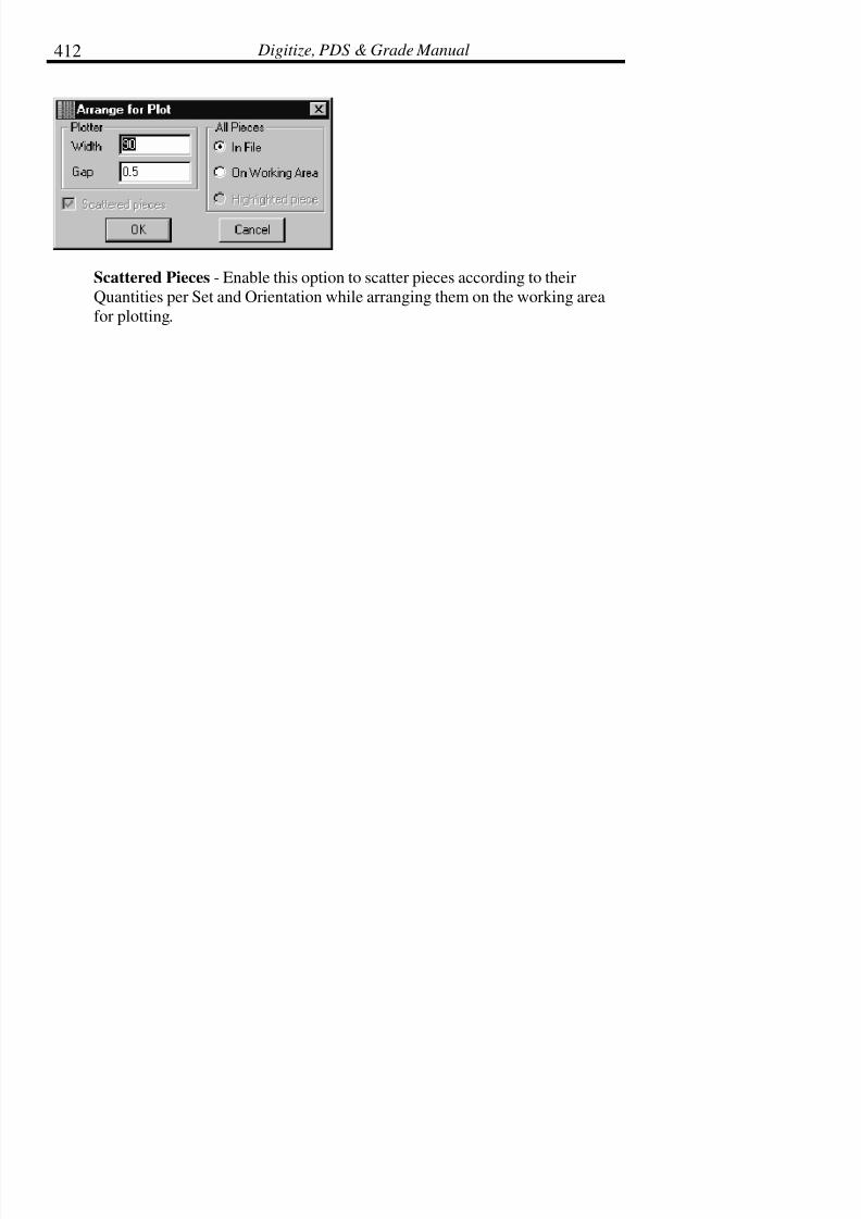
7/28/2019 OptiTex PDS User Manual
http://slidepdf.com/reader/full/optitex-pds-user-manual 433/727
Digitize, PDS & Grade Manual412
Scattered Pieces - Enable this option to scatter pieces according to their
Quantities per Set and Orientation while arranging them on the working area
for plotting.

7/28/2019 OptiTex PDS User Manual
http://slidepdf.com/reader/full/optitex-pds-user-manual 434/727
Chapter 10: Template Menu 413
Chapter 10: Template Menu
The Template (TPL) files are drafting tools that are used during the design
process to help build and create new pieces and styles. Templates can be
made from pieces on the screen in the grading package or they can be digitizedinto the computer. For example, pattern-making tools used in manual pattern
making, such a French curve, can be digitized into the system.
Any piece can be chosen and saved as a template, or any template can be
chosen and used as a tool for creating a piece.
The Template Window is a special place reserved for templates. Any templatein use displays in this window which is located at the right hand side of the
screen. If the Template Window is not visible, select Template Window from
the View menu. The window will appear on the right.
Open Library
Select the Open Library command to open a previously saved Template (TPL)file.

7/28/2019 OptiTex PDS User Manual
http://slidepdf.com/reader/full/optitex-pds-user-manual 435/727
Digitize, PDS & Grade Manual414
To Open a Template Library:
• From the Template Menu select Open Library. The TemplateFile dialog box is displayed.
• OPTIONAL: Change to a different drive or directory to select adifferent TPL file.
• Select the desired template library file from the File Name Listfield.
• Click OK. The Choose Template From Library dialog box isdisplayed.
• Select the desired template from the list displayed in the library.
! Note: The description of the selected template displays above the file list
box. This description was entered when the template library wasoriginally created.

7/28/2019 OptiTex PDS User Manual
http://slidepdf.com/reader/full/optitex-pds-user-manual 436/727
Chapter 10: Template Menu 415
• Click on Choose.
• Look for the selected template in the Template Window on theright of the screen.
Click on the template to display it in the working area and work with it.
! Tip: If the template is selected from the Piece Display Bar, copied, then
pasted as a new piece, it will then be treated as a regular pattern
piece and all commands can be used.
Add To Library
Select the Add To Library command to add additional template pieces to aTemplate Library.

7/28/2019 OptiTex PDS User Manual
http://slidepdf.com/reader/full/optitex-pds-user-manual 437/727
Digitize, PDS & Grade Manual416
To add pieces to a Library:
• Select the piece from the working area to be added to the library.
• From the Template Menu select Add to Library. The Save InTemplate File dialog box is displayed
• Select the desired option.
• Click OK. The selected piece(s) are added to the currenttemplate library.
! Tip: To view the new template pieces, select Choose from the Template
menu.
Save As
Select the Save As command to save the selected piece(s) as a new TemplateLibrary.
To Save a New Template Library:
• Open the selected style file that includes the pattern piece(s) tobe saved as a template library.
• OPTIONAL: To save individual patterns piece in the templatelibrary and display them on the working area.
•
From the Template Menu select Save As. The Save As dialogbox is displayed.
• Type a name for the new template library in the File Name field.
• OPTIONAL: Change to a different drive and directory if youwant to save the library in a location other than the default.
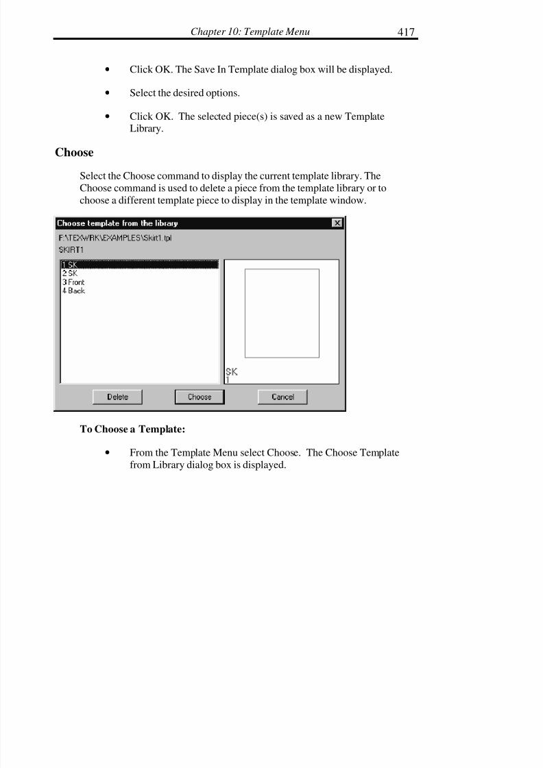
7/28/2019 OptiTex PDS User Manual
http://slidepdf.com/reader/full/optitex-pds-user-manual 438/727
Chapter 10: Template Menu 417
• Click OK. The Save In Template dialog box will be displayed.
• Select the desired options.
• Click OK. The selected piece(s) is saved as a new TemplateLibrary.
Choose
Select the Choose command to display the current template library. The
Choose command is used to delete a piece from the template library or to
choose a different template piece to display in the template window.
To Choose a Template:
• From the Template Menu select Choose. The Choose Template
from Library dialog box is displayed.

7/28/2019 OptiTex PDS User Manual
http://slidepdf.com/reader/full/optitex-pds-user-manual 439/727
Digitize, PDS & Grade Manual418
• Select the desired template piece from the library by clicking onit.
• Click Choose.
The chosen template piece displays in the Template window on the Piece
Display Bar. Refer to the Open Library command discussed earlier in thischapter for more information on working with template pieces.
Primitive Tools Bar:
This new Primitive Tools Bar feature allows the user to create tool bars fromtemplate pieces (any “*.tpl” file).
How to turn your template pieces into a tool bar:
• From Template menu create a template file or load an existing
template file (*.tpl).
• Now save your work and close OptiTex PDS and load again thesoftware.

7/28/2019 OptiTex PDS User Manual
http://slidepdf.com/reader/full/optitex-pds-user-manual 440/727
Chapter 10: Template Menu 419
• Now, go to “View” menu and open Toolbars dialog box:
• Select your Template tool bar from the toolbars list.
Once you created a template tool bar you can use this new tool bar to create
pieces from the template tool.
How to use template tool bar:
• Click on the desirable piece icon from the template tool bar:
• Now click one click with the mouse left button on the workingarea and the image you selected will be pasted on the working
area in 1:1 scale.

7/28/2019 OptiTex PDS User Manual
http://slidepdf.com/reader/full/optitex-pds-user-manual 441/727
Digitize, PDS & Grade Manual420
! Note: You can change the image scale by click and drag the mouse cursor
on the working area. To maintain the image proportions hole the
Shift key while you drag the mouse cursor.
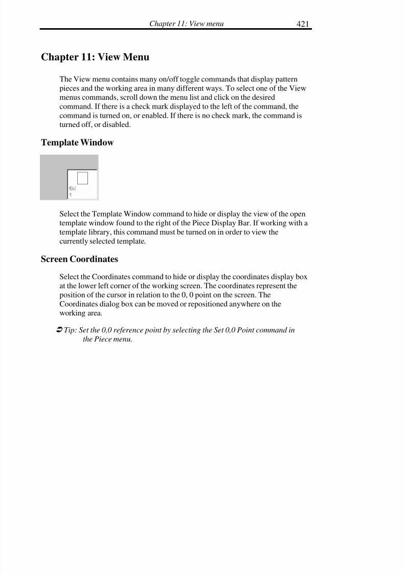
7/28/2019 OptiTex PDS User Manual
http://slidepdf.com/reader/full/optitex-pds-user-manual 442/727
Chapter 11: View menu 421
Chapter 11: View Menu
The View menu contains many on/off toggle commands that display pattern
pieces and the working area in many different ways. To select one of the View
menus commands, scroll down the menu list and click on the desiredcommand. If there is a check mark displayed to the left of the command, the
command is turned on, or enabled. If there is no check mark, the command isturned off, or disabled.
Template Window
Select the Template Window command to hide or display the view of the opentemplate window found to the right of the Piece Display Bar. If working with a
template library, this command must be turned on in order to view the
currently selected template.
Screen Coordinates
Select the Coordinates command to hide or display the coordinates display boxat the lower left corner of the working screen. The coordinates represent the
position of the cursor in relation to the 0, 0 point on the screen. The
Coordinates dialog box can be moved or repositioned anywhere on theworking area.
! Tip: Set the 0,0 reference point by selecting the Set 0,0 Point command in
the Piece menu.

7/28/2019 OptiTex PDS User Manual
http://slidepdf.com/reader/full/optitex-pds-user-manual 443/727
Digitize, PDS & Grade Manual422
Coordinates Dialog Box:
There are two columns in the Screen Coordinates dialog box. The left columnis the X coordinate and the right column is the Y coordinate. The first row
displays the absolute values of the X and Y coordinates from the (0,0) point.
The second row displays the absolute distance. The third row displays thelength of the line created from the first selected point to the second in the X
column while displaying the angle created in a clockwise direction from the
(0,0) point in the Y column.
Rulers
The Rulers option displays the rulers around the working area. You candisable/enable it from View menu by selecting Rulers.
You can also determine the 0,0 point for the ruler:
• Select a required point on a pattern with the cursor.
• From Piece menu select “Set 0,0 point”.
Pieces Bar
Use the Pieces Bar command to hide or display the Piece Display Bar. ThePiece Display Bar is where all pattern pieces contained in the open Style fileare displayed horizontally across the top of the screen. The currently selected
piece in the working area is also highlighted in the Piece Display Bar.
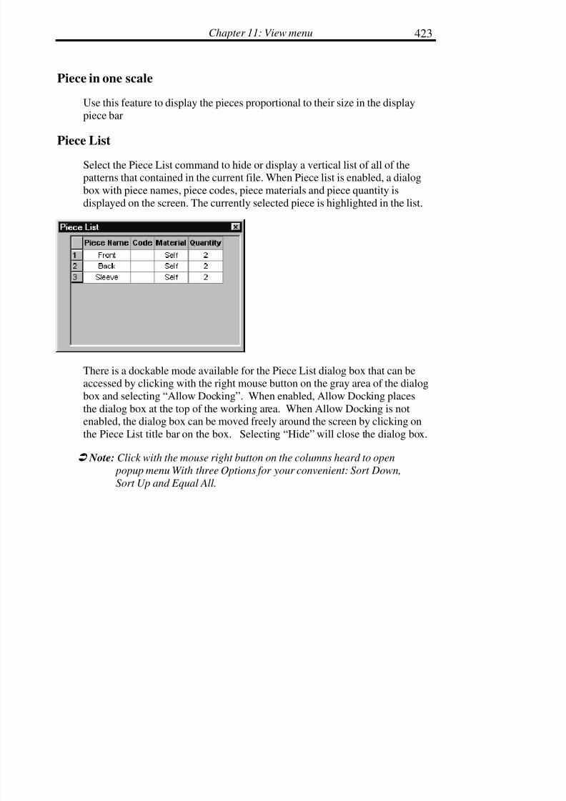
7/28/2019 OptiTex PDS User Manual
http://slidepdf.com/reader/full/optitex-pds-user-manual 444/727
Chapter 11: View menu 423
Piece in one scale
Use this feature to display the pieces proportional to their size in the display
piece bar
Piece List
Select the Piece List command to hide or display a vertical list of all of thepatterns that contained in the current file. When Piece list is enabled, a dialog
box with piece names, piece codes, piece materials and piece quantity is
displayed on the screen. The currently selected piece is highlighted in the list.
There is a dockable mode available for the Piece List dialog box that can beaccessed by clicking with the right mouse button on the gray area of the dialog
box and selecting “Allow Docking”. When enabled, Allow Docking places
the dialog box at the top of the working area. When Allow Docking is not
enabled, the dialog box can be moved freely around the screen by clicking onthe Piece List title bar on the box. Selecting “Hide” will close the dialog box.
! Note: Click with the mouse right button on the columns heard to open
popup menu With three Options for your convenient: Sort Down,
Sort Up and Equal All.

7/28/2019 OptiTex PDS User Manual
http://slidepdf.com/reader/full/optitex-pds-user-manual 445/727
Digitize, PDS & Grade Manual424
Piece Attributes
Enables you to modify piece settings that affect their appearance on the screenas well as for printing/plotting. It has four tabs: Contours, Modes, Internals
and Global.
Contours Tab is divided in two sections: external and internal contour views.

7/28/2019 OptiTex PDS User Manual
http://slidepdf.com/reader/full/optitex-pds-user-manual 446/727
Chapter 11: View menu 425
Modes Tab is divided into two sections: display internals names and display
internals by mode:
Internals Tab is divided into two sections: internals (baseline, contour, circle,
button and text) and notches, darts, pleats section.

7/28/2019 OptiTex PDS User Manual
http://slidepdf.com/reader/full/optitex-pds-user-manual 447/727
Digitize, PDS & Grade Manual426
Global Tab is divided into two sections: piece description and piece view:

7/28/2019 OptiTex PDS User Manual
http://slidepdf.com/reader/full/optitex-pds-user-manual 448/727
Chapter 11: View menu 427
Bubble Info
The Bubble Info command displays useful information such as number, name,
mode, and angle in a “bubble shape” on Points, Notches, Buttons, and Dartswhen there is contact between the element and the mouse cursor. To turn off
the Bubble Info option, check “Don’t Show Bubble Info” at the bottom of thedialog box.
Colors by Mode
Click on Colors by Mode to display a specific color or line type according to
the element attribute. To change Colors by Modes select the Colors optionunder the Options Menu.
To Change Colors by Modes:
• From the Options Menu select Colors and Line Types dialog. TheColor and Line Types dialog box is displayed.

7/28/2019 OptiTex PDS User Manual
http://slidepdf.com/reader/full/optitex-pds-user-manual 449/727
Digitize, PDS & Grade Manual428
• Select Mode.
• Select the mode to change the color or line type.
• Select the new color/line type for the selected mode. The newlyselected color displays to the left of the selected mode.
• Repeat steps 2 and 3 until all modes have been assigned a color.
• Click OK.

7/28/2019 OptiTex PDS User Manual
http://slidepdf.com/reader/full/optitex-pds-user-manual 450/727
Chapter 11: View menu 429
Base Only (F4)
Select the Base Only command to display only the Base Size of the piece. Use
the F4 key to toggle between the base size and the graded sizes.
! Tip: To view only selected sizes, open the Grading Table and place acheck mark next to sizes to be displayed. Uncheck sizes to be
hidden.
Show Seam (Ctrl + F6)
Select this option to display or not display seam contour
Grading Table
Use the Grading Table command to hide or display the Grading Table. The
Grading Table contains grading information such as growth values for delta Xand delta Y on a selected grading points. Most grading operations arecompleted with the grading table displayed.
There is a dockable mode available for the Grading Table dialog box that can
be accessed by clicking with the right mouse button on the gray area of the
dialog box and selecting “Dockable”. When enabled, Dockable places thedialog box at the top of the working area. When Dockable is not enabled, the
dialog box can be moved freely around the screen by clicking on the Piece List
title bar on the box. Selecting “Hide” will close the dialog box.
! Tip: If you resized any of the grading table columns to minimum width and
it disappeared, restore it by resizing the grading table itself
Grading Rules Library
The Grading Library contains information about a new or existing gradinglibrary. This display is most commonly used when editing or creating grade

7/28/2019 OptiTex PDS User Manual
http://slidepdf.com/reader/full/optitex-pds-user-manual 451/727
Digitize, PDS & Grade Manual430
libraries. The table displays on the upper left side of the screen. It is
recommended to disable the grading library display when it is not in use inorder to maximize space in the working area.
There is a dockable mode available for the Grading Rules Library dialog box
that can be accessed by clicking with the right mouse button on the gray area
of the dialog box and selecting “Dockable”. When enabled, Dockable placesthe dialog box at the top of the working area. When Dockable is not enabled,
the dialog box can be moved freely around the screen by clicking on the
Piece List title bar on the box. Selecting “Hide” will close the dialog
box.
Compare Length
Compare length is used to compare lengths between two or more line
segments. Length comparisons are made for all graded sizes. To display theCompare Length dialog box select Compare Length under the View menu.
There is a dockable mode available for the Compare Length dialog box thatcan be accessed by clicking with the right mouse button on the gray area of the
dialog box and selecting “Dockable”. When enabled, Dockable places the
dialog box at the top of the working area. When Dockable is not enabled, thedialog box can be moved freely around the screen by clicking on the Piece List
title bar on the box. Selecting “Hide” will close the dialog box.
To Compare Line Lengths between Two Line Segments:
• Select Compare Length from the View menu.
! Tip: When the Compare Length dialog box displays, it may be necessary to
hide toolbars that are not in use in order to maximizing the working
area. In order to hide toolbars, select Toolbars from the View menu
and uncheck toolbars to hide from view.

7/28/2019 OptiTex PDS User Manual
http://slidepdf.com/reader/full/optitex-pds-user-manual 452/727
Chapter 11: View menu 431
• Select the first segment for comparison, and press the plus sign at
the bottom left side of the dialog box. Notice that the segmentlength for each size displays in the first column in the table. This
column is highlighted in white.
• Select the segment to compare to the first segment. Press theminus sign at the bottom left of the dialog box. Notice that the
segment length for each size displays in the third column in thetable. This column is also highlighted in white.
• Scroll to the far right of the dialog box using the small black arrow at the bottom right of the box. Look for a column called
“delta.” The Delta column, highlighted in green, shows the
difference in length between the two segments.
• Click on the Clear button to clear all line lengths from the table.
• To turn the Compare Length Table off, uncheck Compare Length
in the View menu.
Comparison of multiple line segments may also be done using the Compare
Length feature.
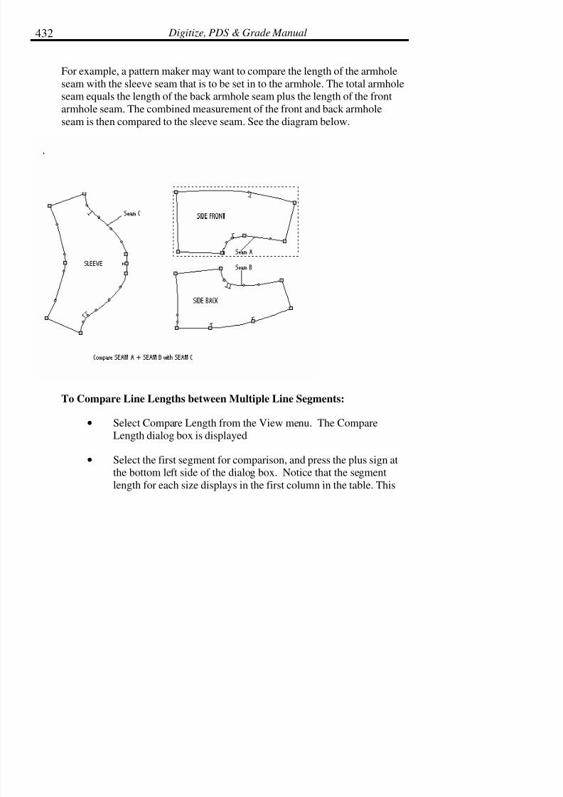
7/28/2019 OptiTex PDS User Manual
http://slidepdf.com/reader/full/optitex-pds-user-manual 453/727

7/28/2019 OptiTex PDS User Manual
http://slidepdf.com/reader/full/optitex-pds-user-manual 454/727
Chapter 11: View menu 433
column is highlighted in white.
• Select the second segment to be added to the first segment. Pressthe plus sign at the bottom left side of the dialog box. Notice that
the segment length for each size displays in a second additionalcolumn. This column is also highlighted in white.
• Notice that the sum of the two lines segments appears in the thirdcolumn from the left. This column is highlighted in gray.
• Select the segment to compare to the combined first twosegments. Press the minus sign at the bottom left of the dialog
box. Notice that the segment length for each size displays in the
fourth column in the table. This column is also highlighted inwhite.
• Scroll to the far right of the dialog box using the small black
arrow at the bottom right of the box. Look for a column called“delta.” The Delta column, highlighted in green, shows the
difference in length between the first two combined segments andthe third segment.
• Click on the Clear button to clear all line lengths from the table.
• To turn the Compare Length Table off, uncheck Compare Lengthin the View menu.
! Note: The three Dialogs: Grading Table, Grading Library and Compare
Length can be dockable. To change a dialog to dockable dialog,click on the mouse right button when the mouse cursor is located on
the top of the dialog (under the dialog header). A right “pop menu”
will be open, check the “Dockable” option.
7/28/2019 OptiTex PDS User Manual
http://slidepdf.com/reader/full/optitex-pds-user-manual 455/727
Digitize, PDS & Grade Manual434
Segment Length
Click on this button to use the Segment Length Option. For more information
on Segment Length see the Design Chapter.
Copy
Choose this option to select values to copy and paste. Select columns by bring
the cursor to the top of the column. The cursor will turn to a black arrow, andthen click on the mouse left button (the selected column will turn to black).
After you selected a column, use the copy button to copy values from one
column to another.
Update Measurement
Choose this option when you want to update the compare length table after
you made changes on the compare segments.
Clear
Choose this option to delete all the previous values from the compare length
table to start a new measure.
Calculator
This command will display a calculator on the screen and can be used while
working.

7/28/2019 OptiTex PDS User Manual
http://slidepdf.com/reader/full/optitex-pds-user-manual 456/727
Chapter 11: View menu 435
Tool Bars
The Tool Bars option in the View Menu controls the tool bars that aredisplayed on the screen. Each toolbar consists of a row of icons (small
pictures) that symbolize the function of each tool. Many of the tools are also
available in pull down menus. When all toolbars are displayed, the workingarea is smaller. Not all toolbars have to be visible at all times. To turn a tool
bar on or off select the tool bar. A check will appear next to the tool bars that
are turned on or displayed.
There are eight toolbars by default:
• System Tools
• General Tools
• Accessories Tools
• Edit Tools
• Insert Tools

7/28/2019 OptiTex PDS User Manual
http://slidepdf.com/reader/full/optitex-pds-user-manual 457/727
Digitize, PDS & Grade Manual436
• Grading Tools
• Dimension Tools
• Advanced Tools
• Dart Tools
• Template Basic Shapes (example of Template toolbar)
To Customize a Toolbar:
• From the View menu, select Tool Bars.
• Click on Customize.
• Click on New. Name the new toolbar.
• Click OK. The toolbar will display under the Toolbars tab and onthe working screen.
• Select the Tools tab. On the right, the buttons are displayed forthe highlighted toolbar on the left.
• Select the button to be placed in the new toolbar. A description of
that button will display at the bottom of the dialog box.
• Click and drag the button from the dialog box to the new toolbar
on the working screen.
• Lift the mouse button to drop the button into the toolbar. Repeatthis until all desired buttons are placed in the toolbar.
• Click OK.

7/28/2019 OptiTex PDS User Manual
http://slidepdf.com/reader/full/optitex-pds-user-manual 458/727
Chapter 11: View menu 437
! Note: The buttons from the Template Basic Shapes toolbar cannot be
transferred to a customized toolbar.
To Reset a Toolbar:
Resetting a toolbar replaces any buttons that were taken out of a default
toolbar.
• From the View menu, select Tool Bars.
• Highlight the desired toolbar.
• Click Reset.
• Click Close.
! Note: The Reset command changes to the Delete command when a
customized toolbar or a Template toolbar is highlighted.
To Create a Template Toolbar:
A Template Toolbar is a toolbar in which the buttons are pattern pieces, whichcan be stretched to a desired length and width.
• Save your file as a Template (From the Template menu, selectSave As.)
• Exit PDS.
• Open PDS.
• From the View menu, select Tool Bars. The Template will beadded to the bottom of the Toolbar list.

7/28/2019 OptiTex PDS User Manual
http://slidepdf.com/reader/full/optitex-pds-user-manual 459/727
Digitize, PDS & Grade Manual438
Status Bar
Select the Status Bar command to hide or display the Status Bar displayedbelow the working area of the screen. The Status Bar displays information
about the type of tool currently in use. Turning off the display of the StatusBar enlarges the working area.
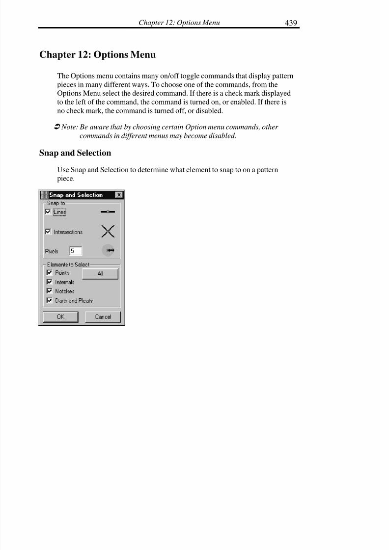
7/28/2019 OptiTex PDS User Manual
http://slidepdf.com/reader/full/optitex-pds-user-manual 460/727
Chapter 12: Options Menu 439
Chapter 12: Options Menu
The Options menu contains many on/off toggle commands that display pattern
pieces in many different ways. To choose one of the commands, from the
Options Menu select the desired command. If there is a check mark displayedto the left of the command, the command is turned on, or enabled. If there is
no check mark, the command is turned off, or disabled.
! Note: Be aware that by choosing certain Option menu commands, other
commands in different menus may become disabled.
Snap and Selection
Use Snap and Selection to determine what element to snap to on a patternpiece.

7/28/2019 OptiTex PDS User Manual
http://slidepdf.com/reader/full/optitex-pds-user-manual 461/727
Digitize, PDS & Grade Manual440
Snap:
Use snap to setup the distance in which the cursor selection will snap onto a
line or a point.
A common setting for this option is 5 pixels. When the computer is set at 5
pixels, the cursor selection will snap to the nearest line or intersection within 5pixels of space.
Element to select:
Sometimes when elements are close to each other on the screen, it is difficult
to select the appropriate element. This command tells the computer to only
select one type of element on the next mouse click.
For example, if there are several points near a notch, and the notch is the
element that the user is trying to select, but the user has difficulty selecting the
notch (due to all the points in the way), the Elements to Select command maybe used in order to establish that the computer only select a notch on the next
mouse click.
The default setting for the Elements to Select command is All; If the Elementsare changed, the change is only applicable on the next mouse click. After the
next mouse click is completed, the options default back to All.
Draft Setup
The Draft Setup option determines if the draft tool will default to internal or
external to your selected piece.
The Draft Setup dialog box has two commands in order to enable you to
choose the draft properties.
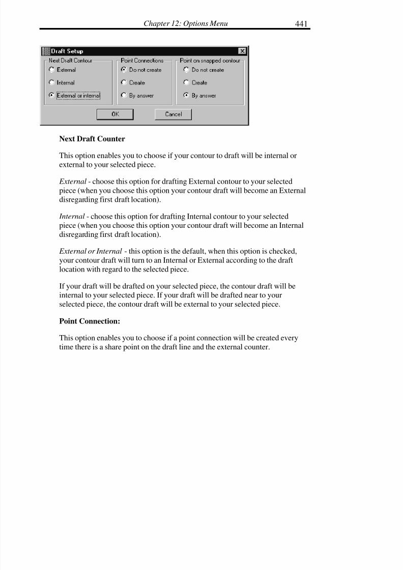
7/28/2019 OptiTex PDS User Manual
http://slidepdf.com/reader/full/optitex-pds-user-manual 462/727
Chapter 12: Options Menu 441
Next Draft Counter
This option enables you to choose if your contour to draft will be internal or
external to your selected piece.
External - choose this option for drafting External contour to your selected
piece (when you choose this option your contour draft will become an External
disregarding first draft location).
Internal - choose this option for drafting Internal contour to your selectedpiece (when you choose this option your contour draft will become an Internal
disregarding first draft location).
External or Internal - this option is the default, when this option is checked,
your contour draft will turn to an Internal or External according to the draft
location with regard to the selected piece.
If your draft will be drafted on your selected piece, the contour draft will beinternal to your selected piece. If your draft will be drafted near to your
selected piece, the contour draft will be external to your selected piece.
Point Connection:
This option enables you to choose if a point connection will be created every
time there is a share point on the draft line and the external counter.
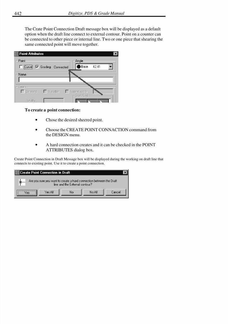
7/28/2019 OptiTex PDS User Manual
http://slidepdf.com/reader/full/optitex-pds-user-manual 463/727
Digitize, PDS & Grade Manual442
The Crate Point Connection Draft message box will be displayed as a default
option when the draft line connect to external contour. Point on a counter canbe connected to other piece or internal line. Two or one piece that shearing the
same connected point will move together.
To create a point connection:
• Chose the desired sheered point.
• Choose the CREATE POINT CONNACTION command fromthe DESIGN menu.
• A hard connection creates and it can be checked in the POINT
ATTRIBUTES dialog box.
Create Point Connection in Draft Message box will be displayed during the working on draft line that
connects to existing point. Use it to create a point connection.

7/28/2019 OptiTex PDS User Manual
http://slidepdf.com/reader/full/optitex-pds-user-manual 464/727
Chapter 12: Options Menu 443
Grid and Stripes
Use Grid and Stripes option to set up a grid on the screen or to set stripes onthe screen. The Grid is useful when performing interactive editing commands.
Stripes are useful to view how a pattern will work on a striped material. Both
grid and stripe dimensions can be set up using the Grid and Stripes DialogBox.
Grid and Stripes Dialog Box:
! Tip: Use the F-7 key to snap the cursor to the closest grid point.
7/28/2019 OptiTex PDS User Manual
http://slidepdf.com/reader/full/optitex-pds-user-manual 465/727
Digitize, PDS & Grade Manual444
Colors and Line Types
The Color and Line Types command is used to determine a specific color for
each size within a design file.
To Change Color for General:
(Line type does not apply to General objects):
• From the Options menu, select Color & Line Types.
• Under Object Types, select General.
• Click on the desired object on the left.
• Click on the desired color on the right.
• Click Apply to view.
• Click OK or Close to accept.
Background – the working screen
Custom Fit – the old version of made-to-measure
Highlight Color – the color of an element such as point, notch, or button
when the cursor is on it
Template – the pieces in a template file
Grids – the grid when enabled under the Options menu
Stripes – the stripes when enabled under the Options menu

7/28/2019 OptiTex PDS User Manual
http://slidepdf.com/reader/full/optitex-pds-user-manual 466/727
Chapter 12: Options Menu 445
Digitizer Menu – If using a Digitizer Menu, will appear this color on the
Digitizer screen.
Digitizer Panel - If using a Digitizer Panel, will appear this color on theDigitizer screen.
Piece List Color – The color of the pieces in the Piece List
Piece List Background – The background of the Piece List
Selected Point Notch – The color of the notch when the corresponding pointis selected (the point connected to the notch).
Guide Line Color – The color of a Guide Line (created under the Piece menu
or pulled from the edge of the working screen).
Work Chain Color – The color of the line(s)/piece involved in a function
such as drafting, moving a point, rotating a piece, etc.
Mark Point Color – The color of the point marked when drafting, moving a
point, placing a button, etc.
Selected Piece Color – The color of the Selected Piece (the piece with the
dotted-line box around it).
To Change Colors for Sizes:
• From the Options Menu select Colors and Line Types. TheColor and Line Types dialog box is displayed.
• Select the size on which to change the color or the line type.
• Select the new color/line type for the selected size. The newlyselected color/line type displays to the left of the selected size.
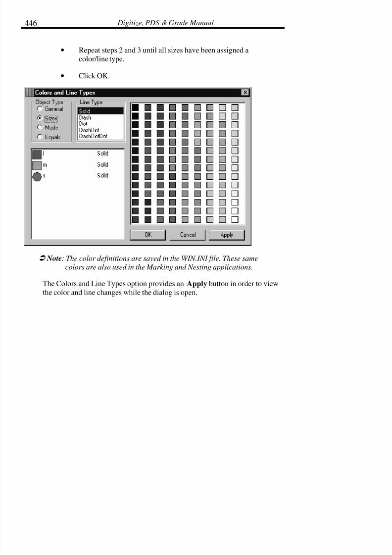
7/28/2019 OptiTex PDS User Manual
http://slidepdf.com/reader/full/optitex-pds-user-manual 467/727
Digitize, PDS & Grade Manual446
• Repeat steps 2 and 3 until all sizes have been assigned acolor/line type.
• Click OK.
! Note: The color definitions are saved in the WIN.INI file. These same
colors are also used in the Marking and Nesting applications.
The Colors and Line Types option provides an Apply button in order to view
the color and line changes while the dialog is open.
7/28/2019 OptiTex PDS User Manual
http://slidepdf.com/reader/full/optitex-pds-user-manual 468/727
Chapter 12: Options Menu 447
To Change Color for Equals:
Equals define the color for Equal Segments created under the Design menu.
• From the Options menu, select Color & Line Types.
• Under Object Types, select Equals (can only be accessible if Equal Segments Group created).
• Click on the desired Segment Group on the left.
• Click on the desired color on the right.
• Click Apply to view.
• Click OK or Close to accept.
Fonts
Use Fonts to change the size and font of the text used by the text tool.
! Note: Not all fonts that available in the SGS software are, supported by all
plotters and or printers. If the printer or plotter does not support the
selected font, font changes will only be reflected on the screen, not in
the output files.
Working Units
Select the Working Units command to change the current working units toinches, millimeters, centimeters, fractions or decimals. All relevant
calculations and information displays will convert and display according to the
selected units.

7/28/2019 OptiTex PDS User Manual
http://slidepdf.com/reader/full/optitex-pds-user-manual 469/727
Digitize, PDS & Grade Manual448
When using the export to Cad-Cam function, it is important to set the working
units the same in both programs. This option affects the screen prompts anddisplays as well as determining whether or not the file is exported correctly.
Set Your Working Units:
• From the Options Menu select Working Units. The WorkingUnits dialog box is displayed.
• Select the desired working units.
! Note: If working units are in inches, the tolerance value can be set in
either decimal or fractional format by selecting the Decimal Inch
Format option at the bottom of the dialog box.
• Select the desired Tolerance value.
! Note: The tolerance value is used to define to how many decimal places to
round the values.
• Click OK.
• Attach Preview

7/28/2019 OptiTex PDS User Manual
http://slidepdf.com/reader/full/optitex-pds-user-manual 470/727
Chapter 12: Options Menu 449
You can attach a Preview Image to any Opened Style File. The purpose for
this option is; to add some more information about the loaded file and not torely only on the file name. The attached image can come from a scanner as a
Bitmap in a BMP format, or you can use any one of the graphic formats,
which appears in the Attach Preview ‘Open List’. The Default format to be
attached is always the last pieces, which were on the working area while thefile was saved. It is not possible to guarantee the following format from any
kind of graphic application. Therefore if you have any difficulties, please sendus a sample file with all relevant information and we will try to find a solution.
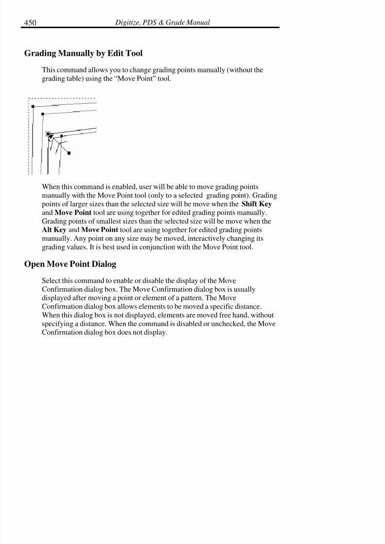
7/28/2019 OptiTex PDS User Manual
http://slidepdf.com/reader/full/optitex-pds-user-manual 471/727
Digitize, PDS & Grade Manual450
Grading Manually by Edit Tool
This command allows you to change grading points manually (without the
grading table) using the “Move Point” tool.
When this command is enabled, user will be able to move grading pointsmanually with the Move Point tool (only to a selected grading point). Grading
points of larger sizes than the selected size will be move when the Shift Key
and Move Point tool are using together for edited grading points manually.
Grading points of smallest sizes than the selected size will be move when the
Alt Key and Move Point tool are using together for edited grading pointsmanually. Any point on any size may be moved, interactively changing its
grading values. It is best used in conjunction with the Move Point tool.
Open Move Point Dialog
Select this command to enable or disable the display of the Move
Confirmation dialog box. The Move Confirmation dialog box is usuallydisplayed after moving a point or element of a pattern. The Move
Confirmation dialog box allows elements to be moved a specific distance.
When this dialog box is not displayed, elements are moved free hand, without
specifying a distance. When the command is disabled or unchecked, the MoveConfirmation dialog box does not display.
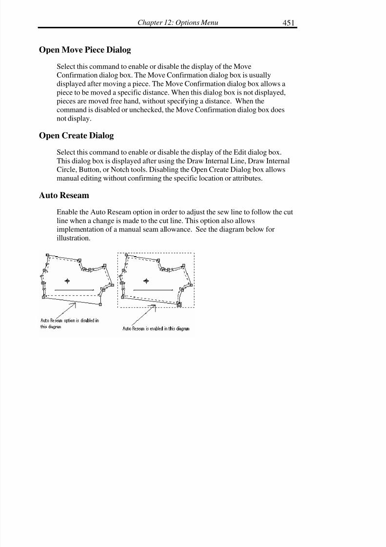
7/28/2019 OptiTex PDS User Manual
http://slidepdf.com/reader/full/optitex-pds-user-manual 472/727
Chapter 12: Options Menu 451
Open Move Piece Dialog
Select this command to enable or disable the display of the MoveConfirmation dialog box. The Move Confirmation dialog box is usually
displayed after moving a piece. The Move Confirmation dialog box allows a
piece to be moved a specific distance. When this dialog box is not displayed,pieces are moved free hand, without specifying a distance. When the
command is disabled or unchecked, the Move Confirmation dialog box does
not display.
Open Create Dialog
Select this command to enable or disable the display of the Edit dialog box.
This dialog box is displayed after using the Draw Internal Line, Draw InternalCircle, Button, or Notch tools. Disabling the Open Create Dialog box allows
manual editing without confirming the specific location or attributes.
Auto Reseam
Enable the Auto Reseam option in order to adjust the sew line to follow the cut
line when a change is made to the cut line. This option also allowsimplementation of a manual seam allowance. See the diagram below for
illustration.

7/28/2019 OptiTex PDS User Manual
http://slidepdf.com/reader/full/optitex-pds-user-manual 473/727
Digitize, PDS & Grade Manual452
Auto Update Notches
Enable the Auto Update Notches command to automatically update notchchanges on the seam contour (without changing the piece contour).
Lock Piece (F3)Select the Lock Piece command to lock the selected pattern piece on the
working area. Once this option is selected, changes to other pattern pieces on
working area can not be made. Only the pattern selected prior to choosing this
command is available for editing or outputting until the command is chosenagain or until exiting the program.
! Note: The F3 key can be used to toggle the Lock function on and off

7/28/2019 OptiTex PDS User Manual
http://slidepdf.com/reader/full/optitex-pds-user-manual 474/727
Chapter 12: Options Menu 453
Preferences
The Preferences option displays a dialog box that allows the user to set
multiple default option or preferences.
Preferences Dialog Box:
Snap Distance
Use snap to setup the distance in which the cursor selection will snap onto a
line or a point. A common setting for this option is 5 pixels. When the
computer is set at 5 pixels, the cursor selection will snap to the nearest line orintersection within 5 pixels of space

7/28/2019 OptiTex PDS User Manual
http://slidepdf.com/reader/full/optitex-pds-user-manual 475/727
Digitize, PDS & Grade Manual454
Minimum Screen Font Size
This option defines the minimum screen font size text viewed on the screen
such as Piece name, Size name, etc. It allows the user to size the view of thetest. It does not affect the size of text to printed or plotted.
! Note: To view Piece information on screen Display as Plot must be
enabled in the Display Piece Attributes option found under the
Display Menu. See the Display Menu chapter for more information.
Button Radius
Define the default size for all newly created buttons
Internal Text Size
Define the default size for internal text
Grading Rules Tables File Extension
Define the default file extension for grading rules tables.
Enable Auto Reseam
Enable the Auto Reseam option in order to adjust the sew line to follow the cutline when a change is made to the cut line. See Auto Reseam above for more
information.
Exclude Darts from Segments Length calculation
Enable this option to measure segments without including the dart.
Auto Update Notches
Enable this option to automatically update all notches.

7/28/2019 OptiTex PDS User Manual
http://slidepdf.com/reader/full/optitex-pds-user-manual 476/727
Chapter 12: Options Menu 455
AutoSave (Backup) file
Click the Browse button to direct the backup file (backup.dsn) to a specific
folder. Define the time interval for automatically saving the current openedfile under AutoSave Interval.
AutoSave Interval
Defines the time interval for automatically saving the currently opened file.This feature creates a backup file titled BACKUP.DSN.
The BACKUP.DSN file can be opened through the Open File dialog box. Use
the backup file if you forget to save a file before shutting the system down or
if the system is shut down incorrectly. After loading the backup and checkingits contents, the file can be saved again under the original file name.
The directory in which your BACKUP.DSN file is saved is determined in your
OPTIKAD.INI file. When installing the program for the first time, you will beasked where you want to place your \TEXWORK\EXAMPLES directory. This
is where the BACKUP.DSP is located.
The AutoSave command is not intended to make backup copies of all files. Itis designed to create a single backup copy of the file currently open in the
event that the system shuts down unexpectedly.
To Set the AutoSave Interval:
• From the OPTIONS menu choose AutoSave.
• When the AutoSave dialog box is displayed, enter the desiredtime. The file is saved every time the determined amount of time
passes.
• Click OK.

7/28/2019 OptiTex PDS User Manual
http://slidepdf.com/reader/full/optitex-pds-user-manual 477/727
Digitize, PDS & Grade Manual456
Working Units
Click on this button to change the Working Units and setup the default
working units for your file.
Colors
Click on the Colors button to make changes to the Colors options.
Fonts
Click on this button to change the Font options. See the Fonts section above.
Notch Parameters
The Default Notch command determines the default notch size and notch type
for all newly created notches.
To Set the Default Notch Type/Size:
• From the Options Menu select Preferences. The Preferencesdialog box is displayed.
• Click on Notch Parameters. The Default Notch Settings dialogbox will display.
• Select the type of notch from the drop down arrow to the right of the box.
• Enter the desired dimensions in the Length and Width fields.
• Enter an angle if the notch should be placed on an angle. (Forexample an outside V notch will have a 180-degree angle.)
• Click OK.
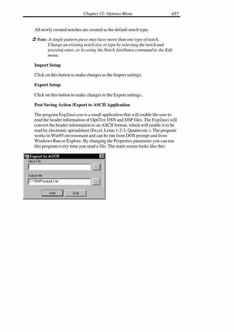
7/28/2019 OptiTex PDS User Manual
http://slidepdf.com/reader/full/optitex-pds-user-manual 478/727
Chapter 12: Options Menu 457
All newly created notches are created as the default notch type.
! Note: A single pattern piece may have more than one type of notch.
Change an existing notch size or type by selecting the notch and
pressing enter, or by using the Notch Attributes command in the Edit
menu.
Import Setup
Click on this button to make changes to the Import settings.
Export Setup
Click on this button to make changes to the Export settings .
Post Saving Action /Export to ASCII Application
The program Exp2asci.exe is a small application that will enable the user toread the header information of OptiTex DSN and DSP files. The Exp2asci will
convert the header information to an ASCII format, which will enable it to be
read by electronic spreadsheet (Excel, Lotus 1-2-3, Quattro etc.). The programworks in Win95 environment and can be run from DOS prompt and from
Windows Run or Explore. By changing the Properties parameter you can run
this program every time you send a file. The main screen looks like this:
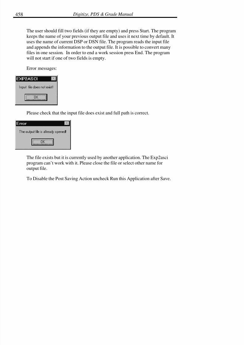
7/28/2019 OptiTex PDS User Manual
http://slidepdf.com/reader/full/optitex-pds-user-manual 479/727
Digitize, PDS & Grade Manual458
The user should fill two fields (if they are empty) and press Start. The program
keeps the name of your previous output file and uses it next time by default. Ituses the name of current DSP or DSN file. The program reads the input file
and appends the information to the output file. It is possible to convert many
files in one session. In order to end a work session press End. The program
will not start if one of two fields is empty.
Error messages:
Please check that the input file does exist and full path is correct.
The file exists but it is currently used by another application. The Exp2asci
program can’t work with it. Please close the file or select other name foroutput file.
To Disable the Post Saving Action uncheck Run this Application after Save.

7/28/2019 OptiTex PDS User Manual
http://slidepdf.com/reader/full/optitex-pds-user-manual 480/727
Chapter 13: Help Menu 459
Chapter 13: Help Menu
The Help menu provides general information and help regarding SGSsoftware.
Index (F1)
The Index command opens on-line help services provided by SGS. This is a
comprehensive guide to product information including a full glossary. This
command works like other on-line Help files; click on the desired topic to
view related information. Information may be viewed on screen or printed outfor future reference.
To access on-line Help:
• From the Help Menu select Index or press F1.
The Command Summary screen will be displayed which offers a completelisting of all the topics in the program. This on-line help program also includes
a Search command, which will search by topic, and a History command,
which will show a log of the recently viewed topics.
Keyboard Map
The Keyboard Map command opens a table of shortcuts that can be veryuseful to you. A new user can print this table and use it as a reference for allavailable keyboard shortcuts.

7/28/2019 OptiTex PDS User Manual
http://slidepdf.com/reader/full/optitex-pds-user-manual 481/727
Digitize, PDS & Grade Manual460
Scenario (Ctrl + F1)
This option will play a short self-running scenario of how to use a specific
Tool.
To use Scenario:
• Select the desired tool.
• Under the Help Menu select Scenario.
• A dialog box with a list of scenarios is displayed.
• Click on one of the options and a self-running demo will start to
play.
Using HelpSelect Using Help to learn the basics of using the on line help program.
Check Plug Protection
The Check Plug Protection option is used to view the plug (key) number. Itmay be necessary to look up this number when calling for technical support.
Check Plug Protection also shows the SGS modules that you are entitled to
use. Furthermore, when purchasing a new SGS module, the Check PlugProtection box is used to enter the codes that activate the new module. In order
to activate a new module, click on the SET button to the right of the new
module listed in the Check Plug Protection dialog, and then enter the twocodes and click OK.

7/28/2019 OptiTex PDS User Manual
http://slidepdf.com/reader/full/optitex-pds-user-manual 482/727
Chapter 13: Help Menu 461
SGS on Line
Enables the user to connect to an Internet browser for access to:
SGS Home Page – Directly links from PDS to SGS Home Page.
SGS Support page – Directly links from PDS to SGS Support Page.
Send File – Sends a DSN file to user’s mailbox without having to attach the
DSN file.
Tip of the Day
Provides you with useful tips on features of PDS.
About OptiTex PDS
Choose the About OptiTex PDS command to find the version of software you
are currently using. This information is necessary when contacting TechnicalSupport for help with your SGS software.

7/28/2019 OptiTex PDS User Manual
http://slidepdf.com/reader/full/optitex-pds-user-manual 483/727
Digitize, PDS & Grade Manual462
Send File
This function enables you to sand a file to any e-mail adders. You can sand it
to mailboxes in your company or around the world. An Internet accessrequired.
To send a file:
• Choose the SEND FILE command from the HELP menu.
• The E-MAIL dialog box appears.
• Enter the e-mail address that you want to send the message to.
• You have the option to attach more files and to add the messagename and subject.

7/28/2019 OptiTex PDS User Manual
http://slidepdf.com/reader/full/optitex-pds-user-manual 484/727
Chapter 13: Help Menu 463
• Click O.K.
• The message with the attached files will be send to the desiredaddress

7/28/2019 OptiTex PDS User Manual
http://slidepdf.com/reader/full/optitex-pds-user-manual 485/727
Digitize, PDS & Grade Manual464
How to Contact SGS
SGS Israel for international sales marketing and technical support:Scanvec Garment Systems (SGS)
Ravnitzky 6
Sgula Industrial Park Petach-Tikva 49221, Israel
Tel.: 972-3-904-9979
Fax: 972-3-904-2710
SGS USA for inside the US sales and marketing:
ScanVec Garment Systems (SGS)
International Plaza Two, Suite 625Philadelphia, PA 19113-1518, USA
Tel.: 610-521-5970 Toll free: (US & Canada) 877 RING OPTI
Fax: 610-521-1564
E-Mail: E-Mail Technical Support: [email protected]
E-Mail Sales & Marketing: [email protected]
Web Site: http://www.optitex.com
7/28/2019 OptiTex PDS User Manual
http://slidepdf.com/reader/full/optitex-pds-user-manual 486/727
Chapter 14: Using the Mouse 465
Chapter 14: Using the Mouse
The mouse is the main pointing device and tool and is used for the majority of
all pattern design, grading, and marking operations. How well the mouse is
handled affects user productivity. Therefore, it is important to understand howto operate the mouse efficiently.
The standard type of mouse used with Microsoft applications has two buttons,
but there are many other compatible mouse devices with three buttons. SGS
software uses only two of the available buttons:
The left button functions as the pointing device and executes most of thecommands. The right mouse button provides quick and easy access to many of
the commands and features in the SGS software.
Right Mouse Button
The right mouse button provides easy access to many SGS commands and
features without having to move the mouse up to the toolbar or up to the pulldown menus. The Right Mouse Button reduces time spent on moving the
cursor around the screen. When used properly, the Right Mouse Button allows
for faster work on a design file.
Anytime while working on a design file, click on the right mouse button to
display a floating pop up menu near the cursor. To activate commands in thepop up menu, click on the command using the left mouse button.

7/28/2019 OptiTex PDS User Manual
http://slidepdf.com/reader/full/optitex-pds-user-manual 487/727
Digitize, PDS & Grade Manual466
Select Tool
Use Select Tool to change the cursor back to the normal arrow pointer. Thiscommand reverts back to the normal arrow pointer when another tool is in use.

7/28/2019 OptiTex PDS User Manual
http://slidepdf.com/reader/full/optitex-pds-user-manual 488/727
Chapter 14: Using the Mouse 467
Edit
Use Edit to quickly access commonly used commands in the Edit pull down
menu such as Undo and Redo.
! Note: Refer to the Edit chapter for more information on Edit commands.

7/28/2019 OptiTex PDS User Manual
http://slidepdf.com/reader/full/optitex-pds-user-manual 489/727
Digitize, PDS & Grade Manual468
Insert
Use the Insert command to insert components such as notches, points, darts,
fullness, pleats, and lines.
! Note: Refer to the Tools chapter for more information on the commands
within the Insert command.
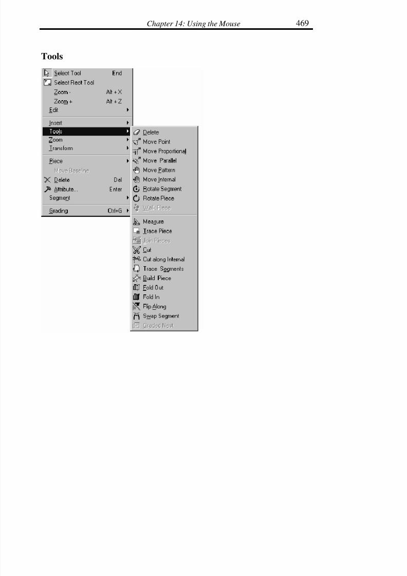
7/28/2019 OptiTex PDS User Manual
http://slidepdf.com/reader/full/optitex-pds-user-manual 490/727
Chapter 14: Using the Mouse 469
Tools

7/28/2019 OptiTex PDS User Manual
http://slidepdf.com/reader/full/optitex-pds-user-manual 491/727
Digitize, PDS & Grade Manual470
Use the Tools command to access many of the tools located on the toolbars
such as Delete, Move, Walk, Circle, Button, and Text.
! Note: Refer to the Tools chapter for more information on the commands
within the Tools command.
Zoom
Use the Zoom command to access the scaling tools used to scale all pieces in
the working area and to enlarge part of the screen.
! Note: Refer to the Tools chapter for more information on the commands
within the Zoom command.

7/28/2019 OptiTex PDS User Manual
http://slidepdf.com/reader/full/optitex-pds-user-manual 492/727
Chapter 14: Using the Mouse 471
Transform
Use the transform command to easily access commands that manipulate
pieces, such as Rotate, Flip, Shrink and Scale.
! Note: Refer to the Piece chapter for more information on the commands
within the Transform command.

7/28/2019 OptiTex PDS User Manual
http://slidepdf.com/reader/full/optitex-pds-user-manual 493/727
Digitize, PDS & Grade Manual472
Piece
Use the Piece command to remove pieces from the working area either by
Removing Current, Replacing Old, or Making New.
! Note: Refer to the Edit chapter under Clear Pieces.
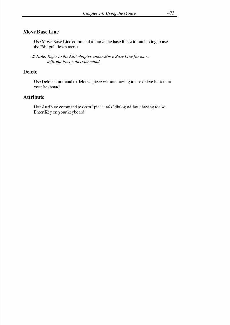
7/28/2019 OptiTex PDS User Manual
http://slidepdf.com/reader/full/optitex-pds-user-manual 494/727
Chapter 14: Using the Mouse 473
Move Base Line
Use Move Base Line command to move the base line without having to use
the Edit pull down menu.
! Note: Refer to the Edit chapter under Move Base Line for moreinformation on this command.
Delete
Use Delete command to delete a piece without having to use delete button on
your keyboard.
Attribute
Use Attribute command to open “piece info” dialog without having to use
Enter Key on your keyboard.
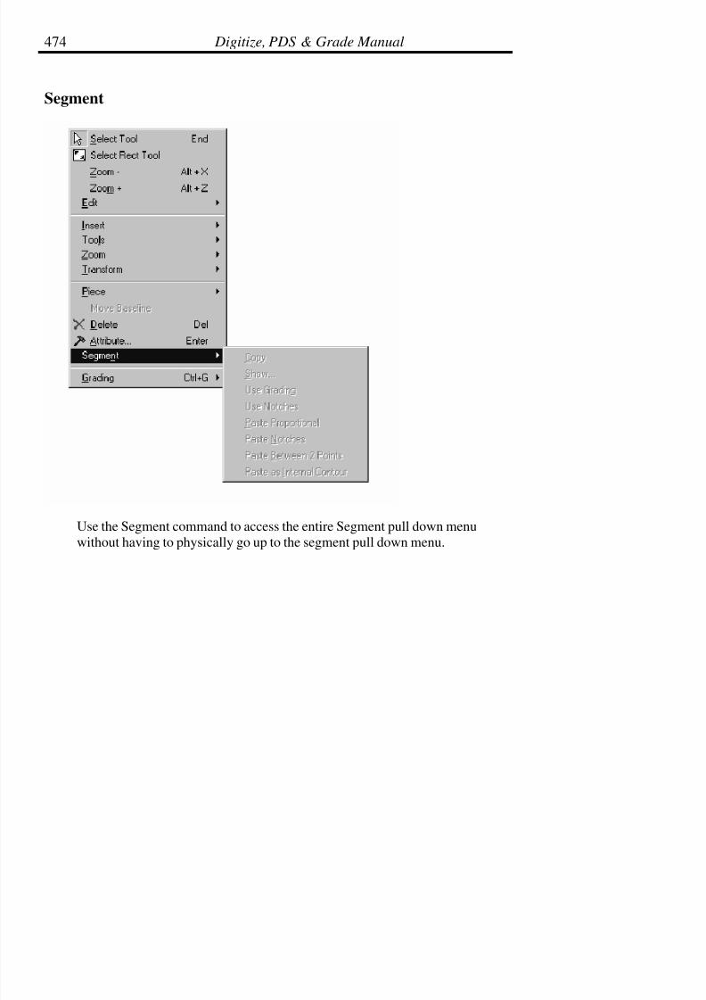
7/28/2019 OptiTex PDS User Manual
http://slidepdf.com/reader/full/optitex-pds-user-manual 495/727
Digitize, PDS & Grade Manual474
Segment
Use the Segment command to access the entire Segment pull down menuwithout having to physically go up to the segment pull down menu.
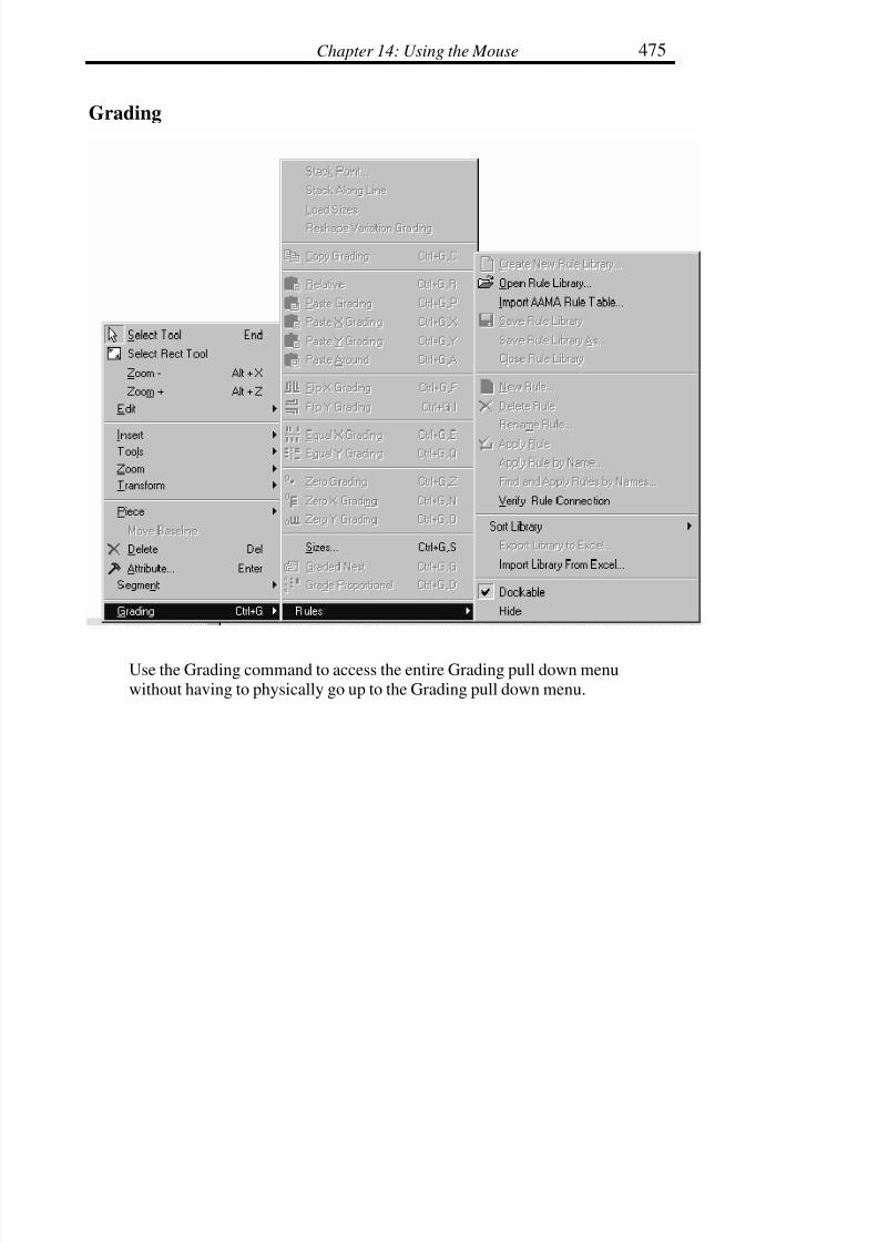
7/28/2019 OptiTex PDS User Manual
http://slidepdf.com/reader/full/optitex-pds-user-manual 496/727
Chapter 14: Using the Mouse 475
Grading
Use the Grading command to access the entire Grading pull down menuwithout having to physically go up to the Grading pull down menu.

7/28/2019 OptiTex PDS User Manual
http://slidepdf.com/reader/full/optitex-pds-user-manual 497/727
Digitize, PDS & Grade Manual476
! Note: Refer to the Grading chapter for more information on the commands
within the Grade command.
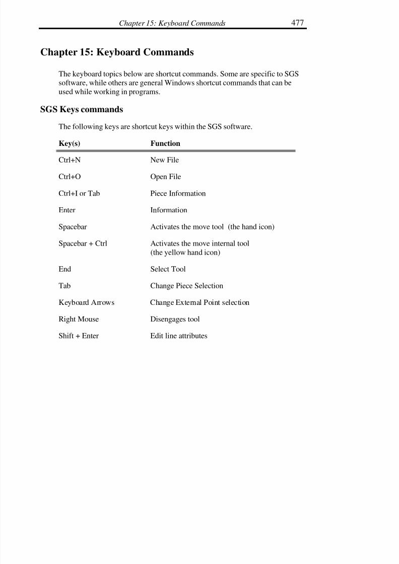
7/28/2019 OptiTex PDS User Manual
http://slidepdf.com/reader/full/optitex-pds-user-manual 498/727
Chapter 15: Keyboard Commands 477
Chapter 15: Keyboard Commands
The keyboard topics below are shortcut commands. Some are specific to SGSsoftware, while others are general Windows shortcut commands that can be
used while working in programs.
SGS Keys commands
The following keys are shortcut keys within the SGS software.
Key(s) Function
Ctrl+N New File
Ctrl+O Open File
Ctrl+I or Tab Piece Information
Enter Information
Spacebar Activates the move tool (the hand icon)
Spacebar + Ctrl Activates the move internal tool
(the yellow hand icon)
End Select Tool
Tab Change Piece Selection
Keyboard Arrows Change External Point selection
Right Mouse Disengages tool
Shift + Enter Edit line attributes

7/28/2019 OptiTex PDS User Manual
http://slidepdf.com/reader/full/optitex-pds-user-manual 499/727
Digitize, PDS & Grade Manual478
This is the list of accelerators that are activated with F keys:
F2:
This key opens the Angle window used with several tools: Cut, Rotate, and
Split.
• Choose Cut icon.
• Click the first point.
• Drag the mouse, moving the cursor toward the opposite contourline facing the next cut point.
• To define an angle for the cut, click the F2 key. Otherwise, holdthe Ctrl key down and click the left mouse button on the
contour.
F3:
Locks the working tools on to the current piece. A second click on F3 unlocks
the cursor from the current piece. The word “Lock” appears at the bottom right
corner of the screen.
F4:
Switches the display of pieces on the working area between Base only and All
Sizes.
F5:
Flips the current active contour (indicated by a solid line) between the innerseam line and the outer perimeter.

7/28/2019 OptiTex PDS User Manual
http://slidepdf.com/reader/full/optitex-pds-user-manual 500/727
Chapter 15: Keyboard Commands 479
F6:
Recalculates the seam if a seam exists. F6 is mainly used after moving points
with seam value.
F7:
Forces the cursor to snap to the nearest grid point regardless the tool type.
F8:
Use this key to display external segment length (contour between two grading
points) and use the Shift key (F8 + Shift) to display internal segment length.
F9:
Use this key as a shortcut to ‘Separate’ Tool
F10:
Use this key to display “Piece Attribute” dialog (from View menu).
F11:
Use this key to change “Walk Direction” when you use the “Walk Tool”.
F12:
Use this key to add notches to pieces (moving and stationary) when you work
with “Walk Tool”. Use Ctrl key and F12 key to add notch only to stationarypiece and Shift key and F12 key to add notch to moving piece.

7/28/2019 OptiTex PDS User Manual
http://slidepdf.com/reader/full/optitex-pds-user-manual 501/727
Digitize, PDS & Grade Manual480
Cursor Movement Keys
Key(s) Function
Direction key Move the cursor left, right, up, or down in
a field.
End, Ctrl+Right Arrow Move to the end of a field.
Home, Ctrl+Left Arrow Move to the beginning of a field.
Page Up, Page Down Move up or down in a field, one
screen at a time.
Tab Move from piece to piece along
the piece bar.
Shift + Tab Move from piece to piece in reverse alongthe piece bar.
Dialog Box Keys
Key(s) Function
Tab Move from field to field within a dialog box.
Shift+Tab Move from field to field in reverse order.
Alt+Letter Move to the selected option or group.
Enter Execute a command button.
Esc Close a dialog box without completing the
command.

7/28/2019 OptiTex PDS User Manual
http://slidepdf.com/reader/full/optitex-pds-user-manual 502/727
Chapter 15: Keyboard Commands 481
Alt+Down Arrow Open a drop-down list box.
Spacebar Cancel a selection in a list box.
Ctrl+ Slash Select all the items in a list box.
Ctrl+Backslash Cancel all selections except the current selection.
Shift+ Home Extend selection to first character in a text box.
Shift+ End Extend selection to last character in a text box.
Editing Keys
Key(s) Function
Backspace Delete the character to the left of the cursor.
Delete Delete the character to the right of the cursor.
Help Keys
Key(s) Function
F1 Open the on-line help program.
F1 + Ctrl Open to Scenario program.
F1 + Shift Create accelerator to the “Context Help Tool”.

7/28/2019 OptiTex PDS User Manual
http://slidepdf.com/reader/full/optitex-pds-user-manual 503/727
Digitize, PDS & Grade Manual482
System Keys
The following keys can be used from any window, regardless of the
application you are using.
Key(s) Function
Ctrl + Esc Switch to the Task List.
Alt + Esc Switch between all open, full screen applications.
Alt + Tab Toggle between all open applications.
Alt + Space Open the Control menu for an application
window.
Alt + Hyphen Open the Control menu for a document window.
Alt + F4 Close a window or open application.
F1 Open the on-line help program.
Text Selection Keys
Key(s) Function
Shift + Arrow Select one character at a time from left to right.
Shift + End Select text to the end of the line.
Shift + Home Select text to the beginning of the line.
Shift + Pg Dn Select text down one full window.
Shift + Pg Up Select text up one full window.

7/28/2019 OptiTex PDS User Manual
http://slidepdf.com/reader/full/optitex-pds-user-manual 504/727
Chapter 15: Keyboard Commands 483
keyboard shortcuts
Key(s) Function
Shift + S (or I) allows snap to Piece internals only.
Ctrl will ignore Snap to any Point objects.
Zoom
Ctrl with Zoom All tool sets Selected Piece on whole screen.
Ctrl with Zoom Real tool sets real scale when current screen center
remains (without the second click)
Shift with Zoom Out increase zoom (Zoom Out counteraction).
Ctrl with Zoom Rectangle works as Zoom Real with center of the rectangle.
Pieces List / Pieces Bar Click
Shift pressed Marks Piece.
Ctrl pressed will Scatter Piece
Ctrl + Shift pressed will remove Scatter copies. From theboard.
Alt pressed will place Piece on its previous on-boardposition anyway.
Digitizer
Ctrl key pressed in Point mode creates non-grade curve Point.

7/28/2019 OptiTex PDS User Manual
http://slidepdf.com/reader/full/optitex-pds-user-manual 505/727
Digitize, PDS & Grade Manual484
Alt + Left-mouse-button provides Undo.
Shift + Left-mouse-button closes Contour.
Drag and Move Tool
Shift + V allows Vertical moving only.
Shift + H allows Horizontal moving only.
Shift + U any moving available.
Grading Manually
Shift during Point Moving will move also all Sizes Greater then current.
Alt during Point Moving will move also all Sizes Less then current.
Round Corner
Shift will solve self-intersection
Shift + Ctrl lets the old (version 7) algorithm to work.
Mirror
Shift sets Notches on mirror line.
Ctrl deletes original Piece after Mirror.
Darts
Alt with Create Dart tool works as Open Dart.
Alt with Move Dart tool allows center rotation do not be center of Dart.

7/28/2019 OptiTex PDS User Manual
http://slidepdf.com/reader/full/optitex-pds-user-manual 506/727
Chapter 15: Keyboard Commands 485
Edit Panel
Tab moves selection to the next Panel field.
Shift + Tab moves selection to the previous Panel field.
Primitive Tool
Shift key pressed will ensure Proportional Scale.
Ctrl key pressed will show Segments Length.
Other
Alt key pressed will ensure appearance of Move Point, MovePiece and Open Create (for Internals) dialogs
even Preference attribute to view such dialogs is
off.
Shift + Z accelerator to Save CUS-file (for Modulate).
Shift key pressed with Text tool allows changing of Piece
Description position.
Shift key pressed during Build Piece exclude area fromPiece.
Shift key pressed will prevent new element creation in
Button, Circle and Notch tools.
Shift key pressed with Add Point tool will add Grade
Point.
Shift key pressed with Cut Piece tool will add Curve and
Non-Grade Point.

7/28/2019 OptiTex PDS User Manual
http://slidepdf.com/reader/full/optitex-pds-user-manual 507/727
Digitize, PDS & Grade Manual486
Shift key pressed with Draft tool will add Curve and
Non-Grade Point.
Shift key pressed in Rotate dialog will choose Piecesgroup (not current only) to Rotate.
Shift key pressed with Adjust Piece Description inGlobal Info dialog will recalculate Description
Center and Angle for all Pieces (regular – forPieces without Descriptions only).
Ctrl key pressed creates the new Guideline (instead of move current).
Ctrl key pressed into in Rules Library and in Sizes
dialog will let to add more then one Size during
Insert / Append command.
Ctrl key pressed allows to Move / Copy more then one
Selected Internals.
Other (alternate actions)
Alt key pressed during Fold In sets Point to Point modefor folding axe selection
Alt key pressed during Move Internal will Join Internalcontours.
Shift key pressed chooses alternate Paste GradingRelative algorithm.
Shift key pressed chooses alternate Move Proportional
algorithm.

7/28/2019 OptiTex PDS User Manual
http://slidepdf.com/reader/full/optitex-pds-user-manual 508/727
Chapter 15: Keyboard Commands 487
Shift key pressed changes Move Internals tool to
work as Copy Internals.
Ctrl key pressed changes Delete Points tool to work as
Close Fullness
PDS ShortCut Keys
KeySpecialkeys
Menucommand
Description
A Alt Zooming Shortcut to ‘Zoom In’ Tool
A Ctrl Draft Tool
dialog
When using the draft tool and the "Move Point"
dialog is disabled, A + Ctrl will open "Angle From
Segment" dialog.
C Ctrl Edit / Copy
Piece
Copy piece to Windows clipboard.
D Ctrl Measure Tool Accelerator
<Insert> Ctrl Edit / Copy
Piece
Copy piece to Windows clipboard.
G Letter on
keyboard
Use for hiding guide lines
G Ctrl Grading / &ldots;
Popup Menu.
HShift Draft Tool Locks the tool for dragging in horizontal direction
M Ctrl Draft Tool
dialog
When using the draft tool and the "Move Point"
dialog is disabled, M + Ctrl will open "PointPosition on Segment " dialog.
I Ctrl Piece /
Info&ldots;
Information & restrictions of selected piece.
N Shift Snaps only to Notches
N Ctrl File / New Close the current Style and create a new.

7/28/2019 OptiTex PDS User Manual
http://slidepdf.com/reader/full/optitex-pds-user-manual 509/727
Digitize, PDS & Grade Manual488
O Ctrl File /
Open&ldots;
Open an existing Style.
R Ctrl Grading / Rules
/ &ldots;
Popup Menu.
P Shift Snaps only to Points
P Ctrl File / Print&ldots;
Print the pieces in the working area.
Space
Key
Ctrl Move Internal Shortcut to ‘Move Internal’ Tool
S Ctrl File / Save Save the current Style.
T Ctrl Draft Tooldialog
When using the draft tool and the "Move Point"dialog is disabled, T + Ctrl will open "Angle To
Segment" dialog.
V Shift Draft Tool
dialog
Locks the tool for dragging in vertical direction
V Ctrl Edit / Paste
Piece
Paste piece from clipboard.
U Shift Draft Tool Cancel Shift+H and Shift+V commands
<Insert> Shift Edit / Paste
Piece
Paste piece from clipboard.
X Alt Zooming Zoom Out
X Ctrl Edit / Cut Piece Remove pieces and put it to Windows clipboard.
<Delete> Shift Edit / Cut Piece Remove pieces and put it to Windows clipboard.
Y Ctrl Edit / Redo Redo.
<backsp
ace>
Shift + Alt Edit / Redo Redo.
Z Alt Zooming Zoom In
Z Ctrl Edit / Undo Undo.
Alt Ctrl Zooming Shortcut to Zoom In on a selected piece
<backsp
ace>
Alt Edit / Undo Undo.
<Delete> Edit / Delete Delete the selected point or internal element.
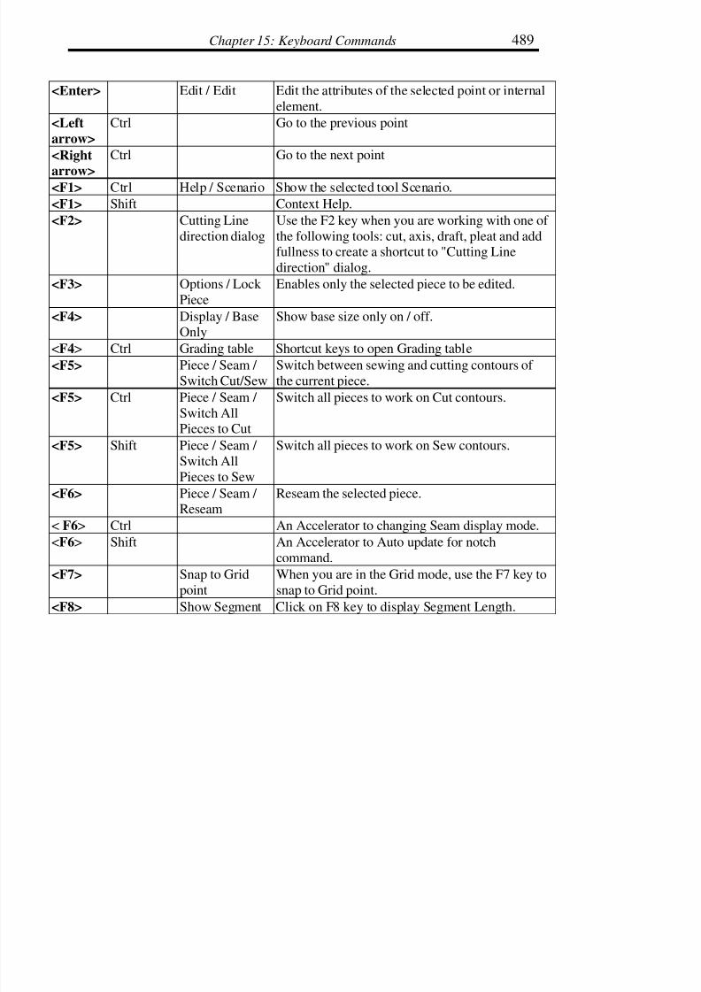
7/28/2019 OptiTex PDS User Manual
http://slidepdf.com/reader/full/optitex-pds-user-manual 510/727
Chapter 15: Keyboard Commands 489
<Enter> Edit / Edit Edit the attributes of the selected point or internal
element.
<Left
arrow>
Ctrl Go to the previous point
<Right
arrow>
Ctrl Go to the next point
<F1> Ctrl Help / Scenario Show the selected tool Scenario.
<F1> Shift Context Help.
<F2> Cutting Line
direction dialog
Use the F2 key when you are working with one of
the following tools: cut, axis, draft, pleat and addfullness to create a shortcut to "Cutting Line
direction" dialog.
<F3> Options / Lock
Piece
Enables only the selected piece to be edited.
<F4> Display / BaseOnly
Show base size only on / off.
<F4> Ctrl Grading table Shortcut keys to open Grading table<F5> Piece / Seam /
Switch Cut/Sew
Switch between sewing and cutting contours of
the current piece.
<F5> Ctrl Piece / Seam /
Switch AllPieces to Cut
Switch all pieces to work on Cut contours.
<F5> Shift Piece / Seam /
Switch All
Pieces to Sew
Switch all pieces to work on Sew contours.
<F6> Piece / Seam / Reseam
Reseam the selected piece.
< F6> Ctrl An Accelerator to changing Seam display mode.<F6> Shift An Accelerator to Auto update for notch
command.
<F7> Snap to Grid
point
When you are in the Grid mode, use the F7 key to
snap to Grid point.
<F8> Show Segment Click on F8 key to display Segment Length.

7/28/2019 OptiTex PDS User Manual
http://slidepdf.com/reader/full/optitex-pds-user-manual 511/727
Digitize, PDS & Grade Manual490
length
<F8> Shift Show Internal
Segment length
Click on F8 with Shift key to display Internal
Segment Length.
<F9> Separate Tool Shortcut Key to the "Separate Tool".
<F10> Display /
Display PieceAttributes&ldots
Display Piece Attributes dialog.
<F11> Piece / Walk /
Switch Direction
Change the walk direction.
<F12> Piece / Walk / Notch Both
Add notches to stationary and moving pieces.
<F12> Ctrl Piece / Walk /
Notch Stationary
Add notches to stationary piece.
<F12> Shift Piece / Walk /
Notch Moving
Add notches to moving piece.

7/28/2019 OptiTex PDS User Manual
http://slidepdf.com/reader/full/optitex-pds-user-manual 512/727
Chapter 16: Digitizer Installation 491
Chapter 16: Digitizer Installation
Installing the Numonics AccuGrid
There are 3 main steps to configuring any digitizer the Numonics AccuGrid
for use with the SGS software: 1) configuring the digitizing tablets, 2)Configuring the serial port, 3) Configuring the digitizer in SGS software.
! Note: Do not install the Numonics Software!
Configuring the Tablet
• Turn off the computer.
• Connect the digitizer to a serial port on the computer,preferably COM1 or COM2. Both the mouse and the digitizer
can be used if they are configured to separate ports.
• Turn on the digitizing tablet and the computer. Tape the SetupMenu Configuration paper that came with the digitizer on the
tablet. This menu can be found on page A11 in the digitizermanual or it may be a loose piece of paper shipped with the
digitizer tablet.
! Note: the next few steps require quiet in order to hear the digitizer sounds.
Do not attempt to proceed with these directions in a working
manufacturing environment.
• To activate the Numonics Softkey Setup Menu, press and holdbutton #1 in the box below MENU on the digitizer tablet. Youwill hear a steady tone, keep the button pressed until the tone
quits. The digitizer will then emit a series of “beeps.”
• Move the crosshair over the MENU ORIGIN mark and press

7/28/2019 OptiTex PDS User Manual
http://slidepdf.com/reader/full/optitex-pds-user-manual 513/727
Digitize, PDS & Grade Manual492
button #1. The MENU ORIGIN mark is a circle with a cross
located at the lower center of the paper menu that is taped to theboard. The digitizer will emit a confirmation chirp.
! Note: The Menu Origin can be found next to the Numonics phone number
on the Setup Menu Configuration sheet that came with the digitizer
tablet.
• Select each option by positioning the crosshair of the digitizerover the box next to the desired setting and press button #1. Youwill hear a series of confirmation chirps after each selection. The
following settings must be selected for use in the SGS Grade,
SGS PDS, or SGS Digitize Software:
Emulation/Output format
Numonics ASCII
ASCII Options
The following are selected: CR, LF, Sep, and Flag
Interface
Baud Rate = 9600
Data Bits = 7
Parity = Even
Stop Bits = 2
Modes
Modes = Point
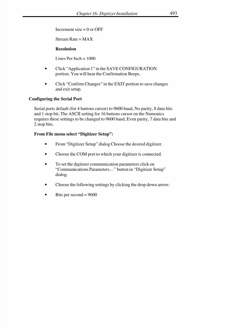
7/28/2019 OptiTex PDS User Manual
http://slidepdf.com/reader/full/optitex-pds-user-manual 514/727
Chapter 16: Digitizer Installation 493
Increment size = 0 or OFF
Stream Rate = MAX
Resolution
Lines Per Inch = 1000
• Click “Application 1” in the SAVE CONFIGURATIONportion. You will hear the Confirmation Beeps.
• Click “Confirm Changes” in the EXIT portion to save changesand exit setup.
Configuring the Serial Port
Serial ports default (for 4 buttons cursor) to 9600 baud, No parity, 8 data bits
and 1 stop bit. The ASCII setting for 16 buttons cursor on the Numonicsrequires these settings to be changed to 9600 baud, Even parity, 7 data bits and2 stop bits.
From File menu select “Digitizer Setup”:
• From “Digitizer Setup” dialog Choose the desired digitizer.
• Choose the COM port to which your digitizer is connected.
• To set the digitizer communication parameters click on
“Communications Parameters…” button in “Digitizer Setup”
dialog.
• Choose the following settings by clicking the drop down arrow:
• Bits per second = 9600

7/28/2019 OptiTex PDS User Manual
http://slidepdf.com/reader/full/optitex-pds-user-manual 515/727
Digitize, PDS & Grade Manual494
Data Bits = 7
Parity = Even
Stop Bits = 2
Flow Control = None
• Click OK to exit and save changes.
Configuring the Digitizer in SGS software
Once the Digitizer is configured and the serial port communications have beenadjusted, configure the SGS software to use the digitizer.
• Start the SGS GRADE, PDS, or DIGITIZE software.
•
From the File menu, choose Digitizer Setup. The “SelectDigitizer” Dialog Box will display.
• Choose the following settings:
Digitizer Type - Select Numonics
Panel - This setting is optional. There is an example panel
included with SGS software located in the Texwork\Examples
directory. Click Browse to locate the available panels. For moreinstructions on the Panel, refer to the Digitizing section of the SGS
User’s manual.
Communication Port - Select the port to which the digitizer is
connected.
Working Units - Select Inches or Millimeters.

7/28/2019 OptiTex PDS User Manual
http://slidepdf.com/reader/full/optitex-pds-user-manual 516/727
Chapter 16: Digitizer Installation 495
Resolution - Set to 1000.00
16 Button Cursor - If using a 16 button digitizer, this option must
be enabled.
Tablet Size - Enable the Set option by clicking in the box next to
SET. An X will display in the box. Enter the actual working areaon the tablet in the appropriate Height and Width fields (for
example, 36 X 48). Values will be displayed in either inches ormillimeters depending on which unit was selected in the Working
Units section.
Shift Digitizer 0/0 Point - Both the X: and Y: values should be set
to 0.
• Click OK to save the settings and exit.
Tips
If the digitizer will not work, check the possible IRQ conflict with the internalfax modem. When using a 4-button cursor, the digitizer works best in Binary
mode. When setting the digitizer to binary mode, the communication
parameters should be set to: 9600,8,n,1
Configuring the GTCO Calcomp Drawing Board 3 Digitizer
Call customer support at 480 948 5508
This digitizer does not support the Numonics ASCII format – it is one
coordinate short.
Customers can try to use the GT ASCII Format 9 or 10 (9 is preferred).

7/28/2019 OptiTex PDS User Manual
http://slidepdf.com/reader/full/optitex-pds-user-manual 517/727
Digitize, PDS & Grade Manual496
Installing the Altek Digitizer For Use With SGS Software
There are 3 main steps to configuring the Altek Digitizer for use with the SGSsoftware: 1) Configuring the digitizing tablet, 2) Configuring the serial port
communications through Windows, and 3) Configuring the digitizer in SGS
software.
! Note: Do not install the Altek Software.
Configuring the Tablet
• Turn off the computer.
• Connect the digitizer to a serial port on the computer, preferablyCOM1 or COM2. Both the mouse and the digitizer can be used
if they are configured to separate ports.
• Turn on the digitizing tablet and the computer. Tape theMovable Menu that came with the digitizer anywhere on thetablet. This menu can be found as a loose piece of laminated
paper shipped with the digitizer tablet.
• *Note: the next few steps require quiet in order to hear thedigitizer sounds. Do not attempt to proceed with these
directions in a working manufacturing environment.
• To activate the Setup Menu, press and hold button #0 or theenter bar on the cursor on the Setup Menu box located in the
fixed bar at the top of the digitizer. You will see flashing lights.
• Move the crosshair over the Moveable Menu and press button#0 on the dot in the lower left corner and then the dot in the
lower right corner. The digitizer will emit a Confirmation Chirp.
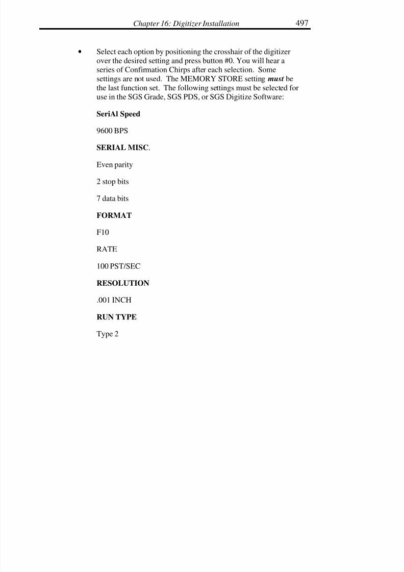
7/28/2019 OptiTex PDS User Manual
http://slidepdf.com/reader/full/optitex-pds-user-manual 518/727
Chapter 16: Digitizer Installation 497
• Select each option by positioning the crosshair of the digitizerover the desired setting and press button #0. You will hear aseries of Confirmation Chirps after each selection. Some
settings are not used. The MEMORY STORE setting must be
the last function set. The following settings must be selected for
use in the SGS Grade, SGS PDS, or SGS Digitize Software:
SeriAl Speed
9600 BPS
SERIAL MISC.
Even parity
2 stop bits
7 data bits
FORMAT
F10
RATE
100 PST/SEC
RESOLUTION
.001 INCH
RUN TYPE
Type 2

7/28/2019 OptiTex PDS User Manual
http://slidepdf.com/reader/full/optitex-pds-user-manual 519/727
Digitize, PDS & Grade Manual498
SOFTWARE
C Numonics
MODE
Point
MISCELLANY
CR on
LF on
Tone on (your option: do you want to hear what you digitize?)
CTS off
MEMORY
Store 1
No confirmation chirp from the controller
• Reselect Setup Menu on the Fixed Bar to exit setup.
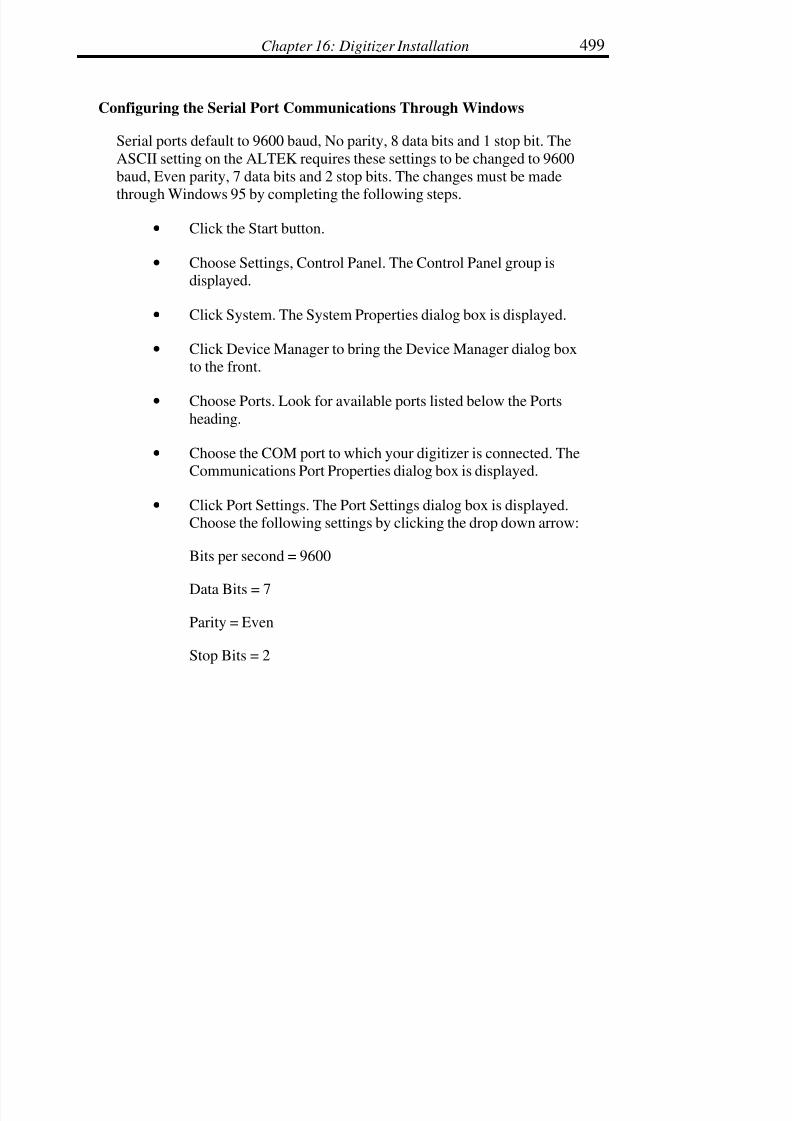
7/28/2019 OptiTex PDS User Manual
http://slidepdf.com/reader/full/optitex-pds-user-manual 520/727
Chapter 16: Digitizer Installation 499
Configuring the Serial Port Communications Through Windows
Serial ports default to 9600 baud, No parity, 8 data bits and 1 stop bit. The
ASCII setting on the ALTEK requires these settings to be changed to 9600
baud, Even parity, 7 data bits and 2 stop bits. The changes must be made
through Windows 95 by completing the following steps.
• Click the Start button.
• Choose Settings, Control Panel. The Control Panel group isdisplayed.
• Click System. The System Properties dialog box is displayed.
• Click Device Manager to bring the Device Manager dialog boxto the front.
• Choose Ports. Look for available ports listed below the Ports
heading.
• Choose the COM port to which your digitizer is connected. TheCommunications Port Properties dialog box is displayed.
• Click Port Settings. The Port Settings dialog box is displayed.Choose the following settings by clicking the drop down arrow:
Bits per second = 9600
Data Bits = 7
Parity = Even
Stop Bits = 2

7/28/2019 OptiTex PDS User Manual
http://slidepdf.com/reader/full/optitex-pds-user-manual 521/727
Digitize, PDS & Grade Manual500
Flow Control = None
• Click OK to exit and save changes. Continue exiting until youare back at the main Windows 95/98/NT screen.
• Restart the computer in order to initialize the port settingchanges made in the steps above. From the Start button, select“Shut Down”. Now select “Restart the Computer.”
Configuring the Digitizer in SGS software
Once the Digitizer is configured and the serial port communications have been
adjusted, configure the SGS software to use the digitizer.
• Start the SGS GRADE, PDS, or DIGITIZE software.
• From the File Menu, select Digitizer Setup. The Select DigitizerDialog Box is displayed.
• Choose the following settings:
Digitizer Type - Select Numonics
Panel - This setting is optional. There is an example panelincluded with SGS software located in the Texwork\Examples
directory. Click BROWSE to locate the available panels. For more
instructions on the Panel, refer to the Digitizing section of the SGS
User’s manual.
Communication Port - Select the port to which the digitizer isconnected.
Working Units - Select Inches or Millimeters.

7/28/2019 OptiTex PDS User Manual
http://slidepdf.com/reader/full/optitex-pds-user-manual 522/727
Chapter 16: Digitizer Installation 501
Resolution - Set to 1000.00
16 Button Cursor - If using a 16 button digitizer, this option must
be enabled.
Tablet Size - Enable the Set option by clicking in the box next to
SET. An X will display in the box. Enter the Actual WorkingArea on the tablet in the appropriate Height and Width boxes (for
example, 36 X 48). Values will display in either Inches orMillimeters depending on which was selected in the Working
Units section.
Shift Digitizer 0/0 Point - Both the X: and Y: values should be set
to 0.
• Click OK to save the settings and exit.
• Exit the SGS Grade, PDS, or Digitize software.
Tips
If the digitizer will not work, try removing the internal fax modem.

7/28/2019 OptiTex PDS User Manual
http://slidepdf.com/reader/full/optitex-pds-user-manual 523/727
Digitize, PDS & Grade Manual502
Installing the GTCO Roll Up Digitizer For Use In SGS software
There are 3 main steps to configuring the GTCO Roll Up Digitizer for use
with the SGS software: configuring the digitizing tablet, the serial portcommunications through Windows and the digitizer in SGS software.
Configuring the Tablet
• 1. Turn your computer off.
• Connect the digitizer to a serial port on the computer, preferablyCOM1 or COM2. Both the mouse and the digitizer can be usedif they are configured to separate ports.
• Choose the Config. button and change the parameters for Bank A and Bank B. The 0 (zero) is OFF, and the 1 (one) is ON.
Switches 1 2 3 4 5 6 7 8
BANK-1 0 0 1 1 1 1 1 0
BANK-2 1 1 1 1 1 1 0 1
BANK-3 1 1 0 0 1 0 0 1
• Turn the digitizing tablet and your computer on.
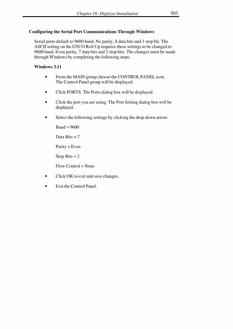
7/28/2019 OptiTex PDS User Manual
http://slidepdf.com/reader/full/optitex-pds-user-manual 524/727
Chapter 16: Digitizer Installation 503
Configuring the Serial Port Communications Through Windows
Serial ports default to 9600 baud, No parity, 8 data bits and 1 stop bit. The
ASCII setting on the GTCO Roll Up requires these settings to be changed to
9600 baud, Even parity, 7 data bits and 2 stop bits. The changes must be made
through Windows by completing the following steps.
Windows 3.11
• From the MAIN group choose the CONTROL PANEL icon.The Control Panel group will be displayed.
• Click PORTS. The Ports dialog box will be displayed.
• Click the port you are using. The Port Setting dialog box will bedisplayed.
• Select the following settings by clicking the drop down arrow:
Baud = 9600
Data Bits = 7
Parity = Even
Stop Bits = 2
Flow Control = None
• Click OK to exit and save changes.
• Exit the Control Panel.

7/28/2019 OptiTex PDS User Manual
http://slidepdf.com/reader/full/optitex-pds-user-manual 525/727
Digitize, PDS & Grade Manual504
Windows 95\98
• Click the START button.
• Choose SETTINGS, CONTROL PANEL. The Control Panelgroup will be displayed.
• Click SYSTEM. The System Properties dialog box will bedisplayed.
• Click DEVICE MANAGER to bring the Device Manager dialogbox to the front.
• Choose PORTS. The available ports will be listed below the
Ports heading.
• Choose the COM port to which your digitizer is connected. The
Communications Port Properties dialog box will be displayed.
• Click PORT SETTINGS. The Port Settings dialog box will bedisplayed. Choose the following settings by clicking the drop
down arrow:
Bits per second = 9600
Data Bits = 7
Parity = Even
Stop Bits = 2
Flow Control = None
• Click OK to exit and save changes. Continue exiting until youare back at the main Windows 95 screen.

7/28/2019 OptiTex PDS User Manual
http://slidepdf.com/reader/full/optitex-pds-user-manual 526/727
Chapter 16: Digitizer Installation 505
Configuring The Digitizer in SGS software
Once the Digitizer is configured and the serial port communications have been
adjusted, you can configure the SGS software to use the digitizer.
• Start the SGS Grade, SGS PDS, or SGS Digitize software.
• From the OPTIONS menu choose DIGITIZER SETUP. TheSelect Digitizer Dialog Box will be displayed.
• Choose the following settings:
Digitizer Type - Select GTCO DIGI-PAD
Panel - This setting is optional. There is an example panel
included with SGS software located in the Texwork\Examples
directory. Click BROWSE to locate the available panels.
Communication Port - Select the port to which your digitizer isconnected.
Working Units - Select Inches or Millimeters.
Resolution - Set to 1000.00
16 Button Cursor - If you are using a 16 button digitizer you mustenable this option.
Tablet Size - Enable the Set option by clicking in the box next toSET. An X will be placed in the box. Enter the Actual Working
Area on the tablet in the appropriate Height and Width boxes.
Values will be displayed in either Inches or Millimeters dependingon which was selected in the Working Units section.

7/28/2019 OptiTex PDS User Manual
http://slidepdf.com/reader/full/optitex-pds-user-manual 527/727
Digitize, PDS & Grade Manual506
Shift Digitizer 0/0 Point - Both the X: and Y: values should be set
to 0.
• Click OK to save the settings and exit.
• Exit the SGS Grade, SGS PDS, or SGS Digitize software..
The next time you enter the SGS Grade, SGS PDS, or SGS Digitize software,
the digitizer will be enabled.
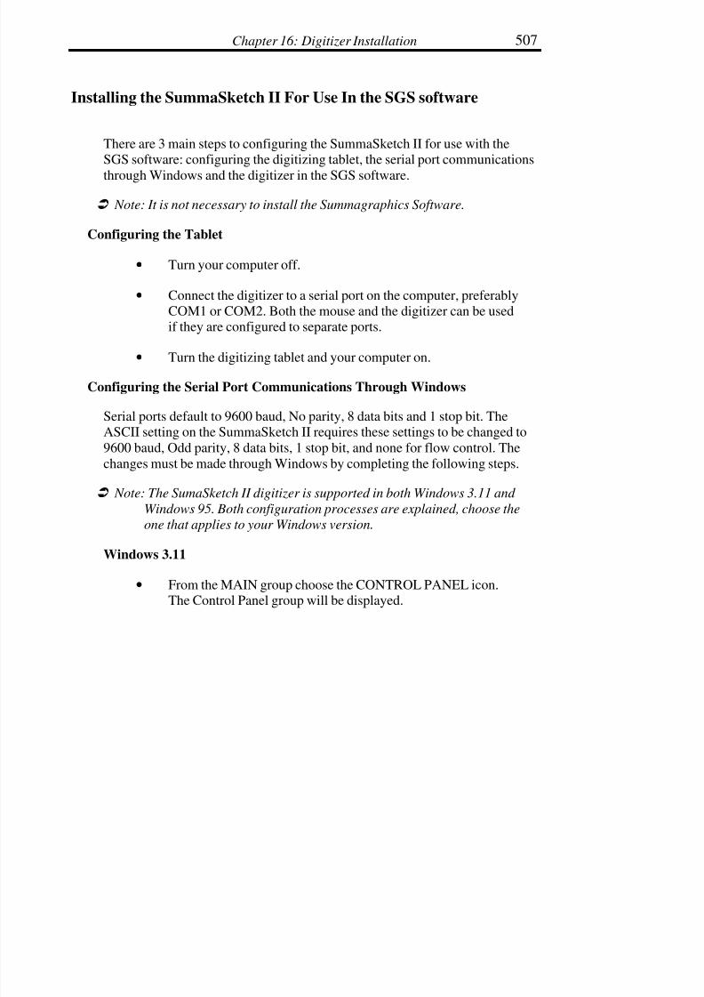
7/28/2019 OptiTex PDS User Manual
http://slidepdf.com/reader/full/optitex-pds-user-manual 528/727
Chapter 16: Digitizer Installation 507
Installing the SummaSketch II For Use In the SGS software
There are 3 main steps to configuring the SummaSketch II for use with theSGS software: configuring the digitizing tablet, the serial port communications
through Windows and the digitizer in the SGS software.
! Note: It is not necessary to install the Summagraphics Software.
Configuring the Tablet
• Turn your computer off.
• Connect the digitizer to a serial port on the computer, preferablyCOM1 or COM2. Both the mouse and the digitizer can be usedif they are configured to separate ports.
• Turn the digitizing tablet and your computer on.
Configuring the Serial Port Communications Through Windows
Serial ports default to 9600 baud, No parity, 8 data bits and 1 stop bit. TheASCII setting on the SummaSketch II requires these settings to be changed to
9600 baud, Odd parity, 8 data bits, 1 stop bit, and none for flow control. The
changes must be made through Windows by completing the following steps.
! Note: The SumaSketch II digitizer is supported in both Windows 3.11 and
Windows 95. Both configuration processes are explained, choose the
one that applies to your Windows version.
Windows 3.11
• From the MAIN group choose the CONTROL PANEL icon.The Control Panel group will be displayed.

7/28/2019 OptiTex PDS User Manual
http://slidepdf.com/reader/full/optitex-pds-user-manual 529/727
Digitize, PDS & Grade Manual508
• Click PORTS. The Ports dialog box will be displayed.
• Click the port you are using. The Port Setting dialog box will bedisplayed.
• Select the following settings by clicking the drop down arrow:
Baud = 9600
Data Bits = 8
Parity = Odd
Stop Bits = 1
Flow Control = None
• Click OK to exit and save changes.
• Exit the Control Panel.
Windows 95/98
• Click the START button.
• Choose SETTINGS, CONTROL PANEL. The Control Panelgroup will be displayed.
• Click SYSTEM. The System Properties dialog box will bedisplayed.
• Click DEVICE MANAGER to bring the Device Manager dialogbox to the front.
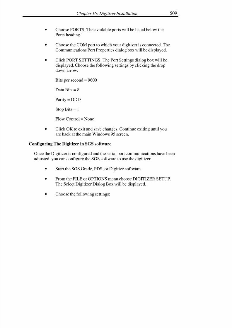
7/28/2019 OptiTex PDS User Manual
http://slidepdf.com/reader/full/optitex-pds-user-manual 530/727
Chapter 16: Digitizer Installation 509
• Choose PORTS. The available ports will be listed below thePorts heading.
• Choose the COM port to which your digitizer is connected. TheCommunications Port Properties dialog box will be displayed.
• Click PORT SETTINGS. The Port Settings dialog box will bedisplayed. Choose the following settings by clicking the dropdown arrow:
Bits per second = 9600
Data Bits = 8
Parity = ODD
Stop Bits = 1
Flow Control = None
• Click OK to exit and save changes. Continue exiting until youare back at the main Windows 95 screen.
Configuring The Digitizer in SGS software
Once the Digitizer is configured and the serial port communications have been
adjusted, you can configure the SGS software to use the digitizer.
• Start the SGS Grade, PDS, or Digitize software.
• From the FILE or OPTIONS menu choose DIGITIZER SETUP.The Select Digitizer Dialog Box will be displayed.
• Choose the following settings:
7/28/2019 OptiTex PDS User Manual
http://slidepdf.com/reader/full/optitex-pds-user-manual 531/727
Digitize, PDS & Grade Manual510
Digitizer Type - Select SummaSketch1212
Panel - This setting is optional. There is an example panel
included with the SGS software located in the Texwork\Examplesdirectory. Click BROWSE to locate the available panels.
Communication Port - Select the port to which your digitizer isconnected.
Working Units - Select Inches or Millimeters.
Resolution - Set to 1000.00
Tablet Size - Enter the Actual Working Area on the tablet in the
appropriate Height and Width boxes. Values will be displayed in
either Inches or Millimeters depending on which was selected in
the Working Units section.
16 Button Cursor - If you are using a 16 button digitizer you mustenable this option.
Shift Digitizer 0/0 Point - Both the X: and Y: values should be set
to 0.
• Click OK to save the settings and exit.
• Exit the SGS Grade, PDS, or Digitize software.
The next time you enter the SGS Grade, PDS, or Digitize software, the
digitizer will be enabled.

7/28/2019 OptiTex PDS User Manual
http://slidepdf.com/reader/full/optitex-pds-user-manual 532/727
Chapter 16: Digitizer Installation 511
Installing the Summagraphic LCL Digitizer For Use In SGS
software
There are 3 main steps to configuring the Summagraphic LCL Digitizer for
use with the SGS software: configuring the digitizing tablet, the serial portcommunications through Windows and the digitizer in SGS software.
Configuring the Tablet
• Turn your computer off.
• Connect the digitizer to a serial port on the computer, preferablyCOM1 or COM2. Both the mouse and the digitizer can be usedif they are configured to separate ports.
•
Choose the Config. button and change the parameters for Set A,B, and C. The 0 (zero) is OFF, and the 1 (one) is ON.
Switches 1 2 3 4 5 6 7 8
SET A 1 0 0 1 1 1 0 0
SET B 1 0 0 1 0 1 0 0
SET C 1 1 0 0 0 0 1 0
! Note: The Summagraphics LCL can binary or as ASCII. The above
switches are for ASCII mode.
• Turn the digitizing tablet and your computer on.
7/28/2019 OptiTex PDS User Manual
http://slidepdf.com/reader/full/optitex-pds-user-manual 533/727
Digitize, PDS & Grade Manual512
Configuring the Serial Port Communications Through Windows
Serial ports default to 9600 baud, No parity, 8 data bits and 1 stop bit. The
Summagraphics LCL digitizer requires 9600, E, 7, 2.
Windows 3.11
• From the MAIN group choose the CONTROL PANEL icon.The Control Panel group will be displayed.
• Click PORTS. The Ports dialog box will be displayed.
• Click the port you are using. The Port Setting dialog box will bedisplayed.
• Select the following settings by clicking the drop down arrow:
Baud = 9600
Data Bits = 7
Parity = Even
Stop Bits = 2
Flow Control = None
•
Click OK to exit and save changes.
• Exit the Control Panel.

7/28/2019 OptiTex PDS User Manual
http://slidepdf.com/reader/full/optitex-pds-user-manual 534/727
Chapter 16: Digitizer Installation 513
Windows 95/98
• Click the START button.
• Choose SETTINGS, CONTROL PANEL. The Control Panelgroup will be displayed.
• Click SYSTEM. The System Properties dialog box will bedisplayed.
• Click DEVICE MANAGER to bring the Device Manager dialogbox to the front.
• Choose PORTS. The available ports will be listed below the
Ports heading.
• Choose the COM port to which your digitizer is connected. The
Communications Port Properties dialog box will be displayed.
• Click PORT SETTINGS. The Port Settings dialog box will bedisplayed. Choose the following settings by clicking the drop
down arrow:
Bits per second = 9600
Data Bits = 7
Parity = Even
Stop Bits = 2
Flow Control = None
• Click OK to exit and save changes. Continue exiting until youare back at the main Windows 95 screen.
7/28/2019 OptiTex PDS User Manual
http://slidepdf.com/reader/full/optitex-pds-user-manual 535/727
Digitize, PDS & Grade Manual514
Configuring The Digitizer in SGS software
Once the Digitizer is configured and the serial port communications have been
adjusted, you can configure the SGS software to use the digitizer.
• Start the SGS Grade, SGS PDS, or SGS Digitize software.
• From the OPTIONS menu choose DIGITIZER SETUP. TheSelect Digitizer Dialog Box will be displayed.
• Choose the following settings:
Digitizer Type - Select Summasketch Professional.
Panel - This setting is optional. There is an example panel
included with SGS software located in the Texwork\Examples
directory. Click BROWSE to locate the available panels.
Communication Port - Select the port to which your digitizer is
connected.
Working Units - Select Inches or Millimeters.
Resolution - Set to 1000.00
16 Button Cursor - If you are using a 16 button digitizer you must
enable this option.
Tablet Size - Enable the Set option by clicking in the box next to
SET. An X will be placed in the box. Enter the Actual WorkingArea on the tablet in the appropriate Height and Width boxes.
Values will be displayed in either Inches or Millimeters depending
on which was selected in the Working Units section.

7/28/2019 OptiTex PDS User Manual
http://slidepdf.com/reader/full/optitex-pds-user-manual 536/727
Chapter 16: Digitizer Installation 515
Shift Digitizer 0/0 Point - Both the X: and Y: values should be
set to 0.
• Click OK to save the settings and exit.
• Exit the SGS Grade, SGS PDS, or SGS Digitize software..
The next time you enter the SGS Grade, SGS PDS, or SGS Digitize software,
the digitizer will be enabled.

7/28/2019 OptiTex PDS User Manual
http://slidepdf.com/reader/full/optitex-pds-user-manual 537/727
Digitize, PDS & Grade Manual516
Installing the GTCO 5A DigiPad Digitizer For Use In SGS software
There are 3 main steps to configuring the GTCO 5A DigiPad Digitizer for use
with the SGS software: 1) Configuring the digitizing tablet, 2) Configuring theserial port communications through Windows, 3) Configuring the digitizer in
SGS software.
Configuring the Tablet
• Turn off the computer.
• Connect the digitizer to a serial port on the computer, preferablyCOM1 or COM2. Both the mouse and the digitizer can be used
if they are configured to separate ports.
! Note: Any serial port can be used. However, keep in mind that on many
computers COM Ports 1 and 3 share the same IRQ and COM ports 2and 4 share the same IRQ. If you have more than 3 serial devices
you may need to change the IRQ setting for one of the COM ports.
For detailed information on IRQ settings refer, to the DOS and
Windows manuals for your system.
• Choose the Config. button and change the parameters for SW 1,2, and 3. The 0 (zero) is OFF, and the 1 (one) is ON.
Switches 1 2 3 4 5 6 7 8
SW-1 0 0 1 1 0 0 0 1
SW-2 1 1 1 1 1 0 0 0
SW-3 0 0 0 0 1 0 0 0
7/28/2019 OptiTex PDS User Manual
http://slidepdf.com/reader/full/optitex-pds-user-manual 538/727
Chapter 16: Digitizer Installation 517
! Note: Bit number 5 in SW3 should be set to ON when using a 16-button
cursor and OFF when using 4 button.
• Turn on the computer and the digitizing tablet.
Configuring the Serial Port Communications Through Windows
Serial ports default to 9600 baud, No parity, 8 data bits and 1 stop bit.
Windows 3.11
• From the MAIN group, choose the CONTROL PANEL icon.The Control Panel group will display.
• Click PORTS. The Ports dialog box will display.
• Click the port to which the digitizer is connected. The Port
Setting dialog box will display.
• Select the following settings by clicking the drop down arrow:
Baud = 9600
Data Bits = 8
Parity = No
Stop Bits = 1
Flow Control = None
• Click OK to exit and save changes.
• Exit the Control Panel.

7/28/2019 OptiTex PDS User Manual
http://slidepdf.com/reader/full/optitex-pds-user-manual 539/727
Digitize, PDS & Grade Manual518
Windows 95/98
• Click the START button.
• Choose SETTINGS, CONTROL PANEL. The Control Panelgroup will display.
• Click SYSTEM. The System Properties dialog box will display.
• Click DEVICE MANAGER to bring the Device Manager dialogbox to the front.
• Choose PORTS. The available ports will be listed below thePorts heading.
• Choose the COM port to which the digitizer is connected. TheCommunications Port Properties dialog box will display.
• Click PORT SETTINGS. The Port Settings dialog box willdisplay. Choose the following settings by clicking the drop
down arrow:
Bits per second = 9600
Data Bits = 8
Parity = No
Stop Bits = 1
Flow Control = None
• Click OK to exit and save changes. Continue exiting until youare back at the main Windows 95 screen.

7/28/2019 OptiTex PDS User Manual
http://slidepdf.com/reader/full/optitex-pds-user-manual 540/727
Chapter 16: Digitizer Installation 519
Configuring The Digitizer in SGS software
Once the Digitizer is configured and the serial port communications have been
adjusted, the next step is to configure the SGS software to use the digitizer.
• Start the SGS Grade, PDS, or Digitize program.
• From the OPTIONS menu, choose DIGITIZER SETUP. TheSelect Digitizer Dialog Box will be displayed.
• Choose the following settings:
Digitizer Type - Select GTCO DIGI-PAD
Panel - This setting is optional. There is an example panel
included with SGS software located in the Texwork\Examples
directory. Click BROWSE to locate the available panels.
Communication Port - Select the port to which the digitizer is
connected.
Working Units - Select Inches or Millimeters.
Resolution - Set to 1000.00
16 Button Cursor - This button must be enabled EVEN if using a
4 button cursor.
Tablet Size - Enable the Set option by clicking in the box next toSET. An X will be placed in the box. Enter the Actual Working
Area on the tablet in the appropriate Height and Width boxes.
Values will be displayed in either Inches or Millimeters dependingon which was selected in the Working Units section.

7/28/2019 OptiTex PDS User Manual
http://slidepdf.com/reader/full/optitex-pds-user-manual 541/727
Digitize, PDS & Grade Manual520
Shift Digitizer 0/0 Point - Both the X: and Y: values should be set
to 0.
• Click OK to save the settings and exit.
• Exit the SGS Grade, SGS PDS, or SGS Digitize software.
The next time you enter the SGS Grade, SGS PDS, or SGS Digitize software,
the digitizer will be enabled.

7/28/2019 OptiTex PDS User Manual
http://slidepdf.com/reader/full/optitex-pds-user-manual 542/727
Chapter 16: Digitizer Installation 521
Installing the MicroGrid IV Digitizer For Use In SGS software
There are 3 main steps to configuring the MicroGrid IV Digitizer for use with
the SGS software: configuring the digitizing tablet, the serial portcommunications through Windows and the digitizer in SGS software.
Configuring the Tablet
• Turn your computer off.
• Connect the digitizer to a serial port on the computer, preferablyCOM1 or COM2. Both the mouse and the digitizer can be usedif they are configured to separate ports.
• Choose the Config. button and change the parameters for SW 1,2, and 3. The 0 (zero) is OFF, and the 1 (one) is ON.
Switches 1 2 3 4 5 6 7 8
SW 1 1 0 0 0 0 0 1 0
SW 2 0 1 1 0 0 1 0 0
SW 3 1 0 0 0 0 1 0 0
• Turn the digitizing tablet and your computer on.
Configuring the Serial Port Communications Through Windows
Serial ports default to 9600 baud, No parity, 8 data bits and 1 stop bit.
Windows 3.11
• From the MAIN group choose the CONTROL PANEL icon.

7/28/2019 OptiTex PDS User Manual
http://slidepdf.com/reader/full/optitex-pds-user-manual 543/727
Digitize, PDS & Grade Manual522
The Control Panel group will be displayed.
• Click PORTS. The Ports dialog box will be displayed.
• Click the port you are using. The Port Setting dialog box will bedisplayed.
• Select the following settings by clicking the drop down arrow:
Baud = 9600
Data Bits = 8
Parity = None
Stop Bits = 1
Flow Control = None
• Click OK to exit and save changes.
• Exit the Control Panel.
Windows 95/98
• Click the START button.
• Choose SETTINGS, CONTROL PANEL. The Control Panel
group will be displayed.
• Click SYSTEM. The System Properties dialog box will bedisplayed.
• Click DEVICE MANAGER to bring the Device Manager dialog

7/28/2019 OptiTex PDS User Manual
http://slidepdf.com/reader/full/optitex-pds-user-manual 544/727
Chapter 16: Digitizer Installation 523
box to the front.
• Choose PORTS. The available ports will be listed below thePorts heading.
• Choose the COM port to which your digitizer is connected. TheCommunications Port Properties dialog box will be displayed.
• Click PORT SETTINGS. The Port Settings dialog box will bedisplayed. Choose the following settings by clicking the dropdown arrow:
Bits per second = 9600
Data Bits = 8
Parity = None
Stop Bits = 1
Flow Control = None
• Click OK to exit and save changes. Continue exiting until youare back at the main Windows 95 screen.
Configuring The Digitizer in SGS software
Once the Digitizer is configured and the serial port communications have been
adjusted, you can configure the SGS software to use the digitizer.
• Start the SGS Grade, SGS PDS, or SGS Digitize software.
• From the OPTIONS menu choose DIGITIZER SETUP. TheSelect Digitizer Dialog Box will be displayed.

7/28/2019 OptiTex PDS User Manual
http://slidepdf.com/reader/full/optitex-pds-user-manual 545/727
Digitize, PDS & Grade Manual524
• Choose the following settings:

7/28/2019 OptiTex PDS User Manual
http://slidepdf.com/reader/full/optitex-pds-user-manual 546/727
Chapter 16: Digitizer Installation 525
Digitizer Type -
Panel - This setting is optional. There is an example panel included
with SGS software located in the Texwork\Examples directory.
Click BROWSE to locate the available panels.
Communication Port - Select the port to which your digitizer isconnected.
Working Units - Select Inches or Millimeters.
Resolution - Set to 1000.00
16 Button Cursor - If you are using a 16 button digitizer you mustenable this option.
Tablet Size - Enable the Set option by clicking in the box next to
SET. An X will be placed in the box. Enter the Actual WorkingArea on the tablet in the appropriate Height and Width boxes.
Values will be displayed in either Inches or Millimeters dependingon which was selected in the Working Units section.
Shift Digitizer 0/0 Point - Both the X: and Y: values should be set
to 0.
• Click OK to save the settings and exit.
• Exit the SGS Grade, SGS PDS, or SGS Digitize software..
The next time you enter the SGS Grade, SGS PDS, or SGS Digitize software,the digitizer will be enabled.

7/28/2019 OptiTex PDS User Manual
http://slidepdf.com/reader/full/optitex-pds-user-manual 547/727
Digitize, PDS & Grade Manual526
Installing the MicroGrid II Digitizer For Use In SGS software
There are 3 main steps to configuring the MicroGrid II Digitizer for use withthe SGS software: configuring the digitizing tablet, the serial port
communications through Windows and the digitizer in SGS software.
Configuring the Tablet
• Turn your computer off.
• Connect the digitizer to a serial port on the computer, preferablyCOM1 or COM2. Both the mouse and the digitizer can be usedif they are configured to separate ports.
• Turn the digitizing tablet and your computer on.
! Note: The MicroGrid II should be set up to work in ASCII mode.
Configuring the Serial Port Communications Through Windows
Serial ports default to 9600 baud, No parity, 8 data bits and 1 stop bit. The
Summagrid Pro IV digitizer requires 9600, E, 7, 2.
Windows 3.11
• From the MAIN group choose the CONTROL PANEL icon.
The Control Panel group will be displayed.
• Click PORTS. The Ports dialog box will be displayed.
• Click the port you are using. The Port Setting dialog box will bedisplayed.
• Select the following settings by clicking the drop down arrow:

7/28/2019 OptiTex PDS User Manual
http://slidepdf.com/reader/full/optitex-pds-user-manual 548/727
Chapter 16: Digitizer Installation 527
Baud = 9600
Data Bits = 7
Parity = Even
Stop Bits = 2
Flow Control = None
• Click OK to exit and save changes.
• Exit the Control Panel.
Windows 95/98
• Click the START button.
• Choose SETTINGS, CONTROL PANEL. The Control Panelgroup will be displayed.
• Click SYSTEM. The System Properties dialog box will be
displayed.
• Click DEVICE MANAGER to bring the Device Manager dialogbox to the front.
•
Choose PORTS. The available ports will be listed below thePorts heading.
• Choose the COM port to which your digitizer is connected. TheCommunications Port Properties dialog box will be displayed.

7/28/2019 OptiTex PDS User Manual
http://slidepdf.com/reader/full/optitex-pds-user-manual 549/727
Digitize, PDS & Grade Manual528
• Click PORT SETTINGS. The Port Settings dialog box will bedisplayed. Choose the following settings by clicking the dropdown arrow:
Bits per second = 9600
Data Bits = 7
Parity = Even
Stop Bits = 2
Flow Control = None
• Click OK to exit and save changes. Continue exiting until youare back at the main Windows 95 screen.
Configuring The Digitizer in SGS software
Once the Digitizer is configured and the serial port communications have been
adjusted, you can configure the SGS software to use the digitizer.
• Start the SGS Grade, SGS PDS, or SGS Digitize software.
• From the OPTIONS menu choose DIGITIZER SETUP. TheSelect Digitizer Dialog Box will be displayed.
• Choose the following settings:
Digitizer Type - Numonics or Summagraphics MicroGrid II
Panel - This setting is optional. There is an example panelincluded with SGS software located in the Texwork\Examples
directory. Click BROWSE to locate the available panels.

7/28/2019 OptiTex PDS User Manual
http://slidepdf.com/reader/full/optitex-pds-user-manual 550/727
Chapter 16: Digitizer Installation 529
Communication Port - Select the port to which your digitizer
is connected.
Working Units - Select Inches or Millimeters.
Resolution - Set to 1000.00
16 Button Cursor - If you are using a 16 button digitizer you must
enable this option.
Tablet Size - Enable the Set option by clicking in the box next toSET. An X will be placed in the box. Enter the Actual Working
Area on the tablet in the appropriate Height and Width boxes.
Values will be displayed in either Inches or Millimeters dependingon which was selected in the Working Units section.
Shift Digitizer 0/0 Point - Both the X: and Y: values should be set
to 0.
• Click OK to save the settings and exit.
• Exit the SGS Grade, SGS PDS, or SGS Digitize software..
The next time you enter the SGS Grade, SGS PDS, or SGS Digitize software,
the digitizer will be enabled.

7/28/2019 OptiTex PDS User Manual
http://slidepdf.com/reader/full/optitex-pds-user-manual 551/727
Digitize, PDS & Grade Manual530
Installing the Summagraphic 4 Button Digitizer For Use In SGS
software
There are 3 main steps to configuring the Summagraphic 4 button Digitizer for
use with the SGS software: configuring the digitizing tablet, the serial port
communications through Windows and the digitizer in SGS software.
Configuring the Tablet
• Turn your computer off.
• Connect the digitizer to a serial port on the computer, preferablyCOM1 or COM2. Both the mouse and the digitizer can be used
if they are configured to separate ports.
• Turn the digitizing tablet and your computer on.
Configuring the Serial Port Communications Through Windows
Serial ports default to 9600 baud, No parity, 8 data bits and 1 stop bit. The
Summagraphics 4 button digitizer requires 9600, O, 8, 1.
Windows 3.11
• From the MAIN group choose the CONTROL PANEL icon.The Control Panel group will be displayed.
• Click PORTS. The Ports dialog box will be displayed.
• Click the port you are using. The Port Setting dialog box will bedisplayed.
• Select the following settings by clicking the drop down arrow:

7/28/2019 OptiTex PDS User Manual
http://slidepdf.com/reader/full/optitex-pds-user-manual 552/727
Chapter 16: Digitizer Installation 531
Baud = 9600
Data Bits = 8
Parity = Odd
Stop Bits = 1
Flow Control = None
• Click OK to exit and save changes.
• Exit the Control Panel.
Windows 95/98
• Click the START button.
• Choose SETTINGS, CONTROL PANEL. The Control Panelgroup will be displayed.
• Click SYSTEM. The System Properties dialog box will be
displayed.
• Click DEVICE MANAGER to bring the Device Manager dialogbox to the front.
• Choose PORTS. The available ports will be listed below thePorts heading.
• Choose the COM port to which your digitizer is connected. TheCommunications Port Properties dialog box will be displayed.
• Click PORT SETTINGS. The Port Settings dialog box will bedisplayed. Choose the following settings by clicking the drop

7/28/2019 OptiTex PDS User Manual
http://slidepdf.com/reader/full/optitex-pds-user-manual 553/727
Digitize, PDS & Grade Manual532
down arrow:
Bits per second = 9600
Data Bits = 8
Parity = Odd
Stop Bits = 1
Flow Control = None
• Click OK to exit and save changes. Continue exiting until youare back at the main Windows 95 screen.
Configuring The Digitizer in SGS software
Once the Digitizer is configured and the serial port communications have beenadjusted, you can configure the SGS software to use the digitizer.
• Start the SGS Grade, SGS PDS, or SGS Digitize software.
• From the OPTIONS menu choose DIGITIZER SETUP. TheSelect Digitizer Dialog Box will be displayed.
• Choose the following settings:
Digitizer Type -
Panel - This setting is optional. There is an example panel includedwith SGS software located in the Texwork\Examples directory.Click BROWSE to locate the available panels.
Communication Port - Select the port to which your digitizer isconnected.

7/28/2019 OptiTex PDS User Manual
http://slidepdf.com/reader/full/optitex-pds-user-manual 554/727
Chapter 16: Digitizer Installation 533
Working Units - Select Inches or Millimeters.
Resolution - Set to 1000.00
16 Button Cursor - If you are using a 16 button digitizer you must
enable this option.
Tablet Size - Enable the Set option by clicking in the box next to
SET. An X will be placed in the box. Enter the Actual WorkingArea on the tablet in the appropriate Height and Width boxes.
Values will be displayed in either Inches or Millimeters depending
on which was selected in the Working Units section.
Shift Digitizer 0/0 Point - Both the X: and Y: values should be setto 0.
• Click OK to save the settings and exit.
• Exit the SGS Grade, SGS PDS, or SGS Digitize software.
The next time you enter the SGS Grade, SGS PDS, or SGS Digitize software,
the digitizer will be enabled.

7/28/2019 OptiTex PDS User Manual
http://slidepdf.com/reader/full/optitex-pds-user-manual 555/727
Digitize, PDS & Grade Manual534
Installing the SummaSketch Professional Digitizer For Use In SGS
software
There are 3 main steps to configuring the SummaSketch Professional Digitizer
for use with the SGS software: configuring the digitizing tablet, the serial port
communications through Windows and the digitizer in SGS software.
Configuring the Tablet
• Turn your computer off.
• Connect the digitizer to a serial port on the computer, preferablyCOM1 or COM2. Both the mouse and the digitizer can be used
if they are configured to separate ports.
• Turn the digitizing tablet and your computer on.
! Note: The SummaSketch Professional 16 Button Digitizer runs in UIOF
mode. The SummaSketch Professional 4 Button Digitizer runs in
Binary mode.
Configuring the Serial Port Communications Through Windows
Serial ports default to 9600 baud, No parity, 8 data bits and 1 stop bit. TheSummaSketch Professional 16 button digitizer requires 9600, E, 7, 2. The
SummaSketch Professional 4 button digitizer requires 9600, o, 8, 1.
Windows 3.11
• From the MAIN group choose the CONTROL PANEL icon.The Control Panel group will be displayed.
• Click PORTS. The Ports dialog box will be displayed.

7/28/2019 OptiTex PDS User Manual
http://slidepdf.com/reader/full/optitex-pds-user-manual 556/727
Chapter 16: Digitizer Installation 535
• Click the port you are using. The Port Setting dialog box willbe displayed.
• Select the following settings by clicking the drop down arrow:
16 Button Cursor settings:
Baud = 9600
Data Bits = 7
Parity = Even
Stop Bits = 2
Flow Control = None
4 Button Cursor settings:
Baud = 9600
Data Bits = 8
Parity = Odd or None
Stop Bits = 1
Flow Control = None
• Click OK to exit and save changes.
• Exit the Control Panel.

7/28/2019 OptiTex PDS User Manual
http://slidepdf.com/reader/full/optitex-pds-user-manual 557/727
Digitize, PDS & Grade Manual536
Windows 95/98
• Click the START button.
• Choose SETTINGS, CONTROL PANEL. The Control Panelgroup will be displayed.
• Click SYSTEM. The System Properties dialog box will bedisplayed.
• Click DEVICE MANAGER to bring the Device Manager dialogbox to the front.
• Choose PORTS. The available ports will be listed below the
Ports heading.
• Choose the COM port to which your digitizer is connected. The
Communications Port Properties dialog box will be displayed.
• Click PORT SETTINGS. The Port Settings dialog box will bedisplayed. Choose the following settings by clicking the drop
down arrow:
16 Button Cursor settings:
Baud = 9600
Data Bits = 7
Parity = Even
Stop Bits = 2
Flow Control = None

7/28/2019 OptiTex PDS User Manual
http://slidepdf.com/reader/full/optitex-pds-user-manual 558/727
Chapter 16: Digitizer Installation 537
4 Button Cursor settings:
Baud = 9600
Data Bits = 8
Parity = Odd or None
Stop Bits = 1
Flow Control = None
• Click OK to exit and save changes. Continue exiting until youare back at the main Windows 95 screen.
Configuring The Digitizer in SGS software
Once the Digitizer is configured and the serial port communications have beenadjusted, you can configure the SGS software to use the digitizer.
• Start the SGS Grade, SGS PDS, or SGS Digitize software.
• From the OPTIONS menu choose DIGITIZER SETUP. TheSelect Digitizer Dialog Box will be displayed.
• Choose the following settings:
Digitizer Type - Select Summasketch Professional.
Panel - This setting is optional. There is an example panelincluded with SGS software located in the Texwork\Examplesdirectory. Click BROWSE to locate the available panels.
Communication Port - Select the port to which your digitizer isconnected.

7/28/2019 OptiTex PDS User Manual
http://slidepdf.com/reader/full/optitex-pds-user-manual 559/727
Digitize, PDS & Grade Manual538
Working Units - Select Inches or Millimeters.
Resolution - Set to 1000.00
16 Button Cursor - If you are using a 16 button digitizer you must
enable this option.
Tablet Size - Enable the Set option by clicking in the box next to
SET. An X will be placed in the box. Enter the Actual WorkingArea on the tablet in the appropriate Height and Width boxes.
Values will be displayed in either Inches or Millimeters depending
on which was selected in the Working Units section.
Shift Digitizer 0/0 Point - Both the X: and Y: values should be setto 0.
• Click OK to save the settings and exit.
• Exit the SGS Grade, SGS PDS, or SGS Digitize software..
The next time you enter the SGS Grade, SGS PDS, or SGS Digitize software,
the digitizer will be enabled.

7/28/2019 OptiTex PDS User Manual
http://slidepdf.com/reader/full/optitex-pds-user-manual 560/727
Chapter 16: Digitizer Installation 539
Digitizer Manufacturers
The following manufacturers offer digitizing devices that are commonly used
and compatible with OptiTex software. SGS recommends that you confirmOptiTex compatibility of specific digitizer models and manufacturers before
making your purchase.
Calcomp
2411 West La Palma Avenue
P.O. Box 3250
Anaheim, CA 92801
Phone: 800-458-5888, 714-821-2000
Fax: 714-821-2045
GTCO Corporation
7125 Riverwood Drive
Columbia, Maryland 21046
Phone: 800-344-4723, 410-381-6688
Fax: 410-290-9065
7/28/2019 OptiTex PDS User Manual
http://slidepdf.com/reader/full/optitex-pds-user-manual 561/727
Digitize, PDS & Grade Manual540
Numonics Corporation
101 Commerce Drive
Box 1005
Montgomeryville, PA 18936
Phone: 800-523-6716, 215-362-2766
Fax: 215-361-0167
Summagraphics Corporation
8500 Cameron Road
Austin, Texas 78754-3999
Phone: 800-444-3425, 512-835-0900
Fax: 512-835-1916

7/28/2019 OptiTex PDS User Manual
http://slidepdf.com/reader/full/optitex-pds-user-manual 562/727
Chapter 17: Output Devices Installation 541
Chapter 17: Output Devices Installation
This chapter will guide how to install and configure a width range of plotters
and cutters types that supported by OptiTex.
Installing Algotex Plotters with SGS Software
Installing the Algotex Software
• Turn off the computer.
• Connect the plotter cable to the parallel port (LPT2) on thecomputer.
• Turn on the computer and the plotter.
•Create a directory called C:\TEXOPLOT\DATA
• Copy all the files on the Algotex diskette into the C:\TEXOPLOTdirectory.
The Algotex diskette contains the following files:
AUTO_DOT.EXEAUTO_DOT.CNF
AUTO_DOT.HLP
AUTO_DOT.TXT
RASTEX.EXETEXOPLOT.ICO
README.DOC
README.TXT
• Copy the ALGOTEXP.CFG file into the C:\TEXOPLOT directory.

7/28/2019 OptiTex PDS User Manual
http://slidepdf.com/reader/full/optitex-pds-user-manual 563/727
Digitize, PDS & Grade Manual542
! Note: The ALGOTEXP.CFG file can be found on the diskette attached to
the plotter.
• Create a directory called C:\OPTITEX\HPGL
• Select START, SETTINGS, TASKBAR, START MENUPROGRAMS, ADD.
• BROWSE for and OPEN the following file.C:\TEXOPLOT\RASTEX.EXE
• Select NEXT. Select the OptiTex Program Group. Type RASTER
as the program name and select FINISH.
• Select ADD, BROWSE for and OPEN the following file.C:\TEXOPLOT\AUTO_DOT.EXE
• Select NEXT. Select the OptiTex Program Group. Type PLOT asthe program name and select FINISH.
• Select ADVANCED, under Start Menu, select the plus (+) sign tothe left of the word “Programs.” Highlight the OptiTex Program
Group. Copy (hold down the shift key and drag) the RASTERprogram and PLOT program on the right side of the screen to the
STARTUP folder on the left side of the screen. You can now
CLOSE.
• Using a text editor, edit the following file.
C:\TEXOPLOT\AUTO_DOT.CNF
• Change the Recovery directory to C:\OPTITEX\HPGL and changethe Raster Data files directory to C:\TEXOPLOT\DATA

7/28/2019 OptiTex PDS User Manual
http://slidepdf.com/reader/full/optitex-pds-user-manual 564/727
Chapter 17: Output Devices Installation 543
• Save the changes to the AUTO_DOT.CNF file and return to theWINDOWS desktop.
• Restart the computer. Select START, SHUTDOWN, RESTARTCOMPUTER.
Configuring the Alogotex Plotter in SGS software.
Once the Algotex software is installed, the SGS software can be configured to
work with the plotter.
• Start the SGS PDS or MARK program.
• From the FILE menu choose PLOTTER SETUP. A Dialog Box is
displayed.
• Uncheck “Use Output Manager.”
• Select OK.
• If in working in PDS, display a piece on the screen. If working inMARK, display a marker on the screen.
• From the FILE menu select PLOT. Select SETUP from the lowerleft side of the dialog box.
• In the Plot Setting Dialog Box select HPGL as the format. InPlotter Page Size, the X must be _____ and the Y must be the width
of the paper (72 inches is the maximum).
• Select OK, the Plot Dialog Box is once again displayed. Make surethat the following settings are unchecked while testing: Output
Manager, Use, Alert on Start, Remove on End, Alert on End.
• Select OK.
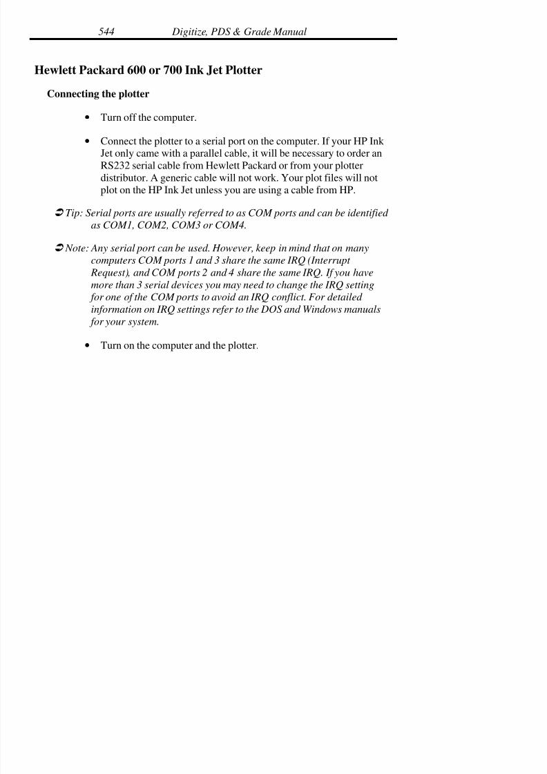
7/28/2019 OptiTex PDS User Manual
http://slidepdf.com/reader/full/optitex-pds-user-manual 565/727
Digitize, PDS & Grade Manual544
Hewlett Packard 600 or 700 Ink Jet Plotter
Connecting the plotter
• Turn off the computer.
• Connect the plotter to a serial port on the computer. If your HP Ink Jet only came with a parallel cable, it will be necessary to order an
RS232 serial cable from Hewlett Packard or from your plotter
distributor. A generic cable will not work. Your plot files will notplot on the HP Ink Jet unless you are using a cable from HP.
! Tip: Serial ports are usually referred to as COM ports and can be identified
as COM1, COM2, COM3 or COM4.
! Note: Any serial port can be used. However, keep in mind that on many
computers COM ports 1 and 3 share the same IRQ (Interrupt
Request), and COM ports 2 and 4 share the same IRQ. If you havemore than 3 serial devices you may need to change the IRQ setting
for one of the COM ports to avoid an IRQ conflict. For detailed
information on IRQ settings refer to the DOS and Windows manuals
for your system.
• Turn on the computer and the plotter.
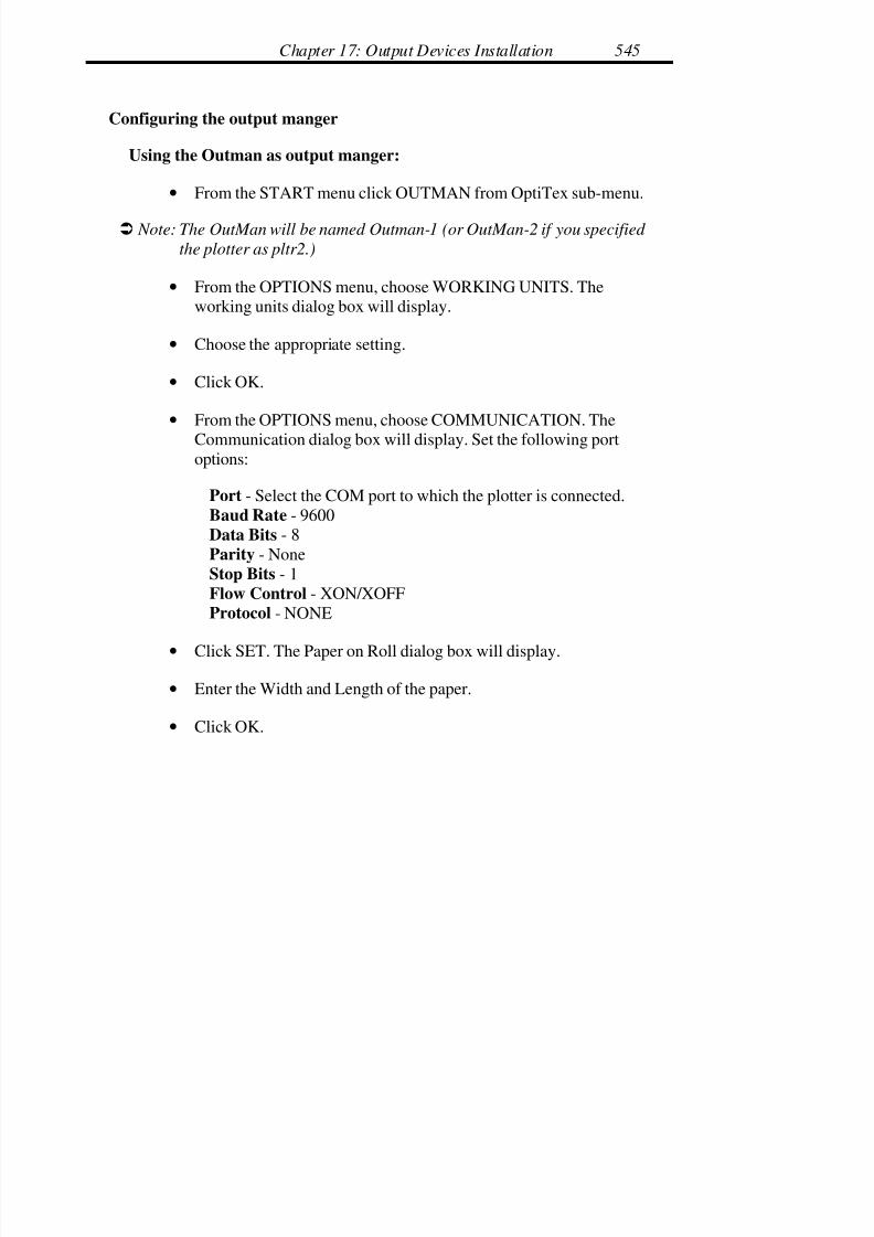
7/28/2019 OptiTex PDS User Manual
http://slidepdf.com/reader/full/optitex-pds-user-manual 566/727
Chapter 17: Output Devices Installation 545
Configuring the output manger
Using the Outman as output manger:
• From the START menu click OUTMAN from OptiTex sub-menu.
! Note: The OutMan will be named Outman-1 (or OutMan-2 if you specified
the plotter as pltr2.)
• From the OPTIONS menu, choose WORKING UNITS. Theworking units dialog box will display.
• Choose the appropriate setting.
• Click OK.
• From the OPTIONS menu, choose COMMUNICATION. The
Communication dialog box will display. Set the following portoptions:
Port - Select the COM port to which the plotter is connected.
Baud Rate - 9600
Data Bits - 8
Parity - None
Stop Bits - 1
Flow Control - XON/XOFF
Protocol - NONE
• Click SET. The Paper on Roll dialog box will display.
• Enter the Width and Length of the paper.
• Click OK.

7/28/2019 OptiTex PDS User Manual
http://slidepdf.com/reader/full/optitex-pds-user-manual 567/727
Digitize, PDS & Grade Manual546
! Note: If the exact length of the paper is unknown, estimate. The length of
the paper needs to be longer than the plot file that will be plotted.
• Minimize the OutMan, keeping it running. Do not close theOutman.
Configuring Qman
• Open the QMan by double clicking on the icon in the STARTmenu. Usually located in START>Optitex 8> Output control>
Qman
• From the FILE menu, choose WORKING UNITS.
• Select the appropriate working units. The selection should match
the working units that were set in the SGS Plot setup dialog box.
OutMan Path Setup
• From the FILE menu, choose PLOT SETUP. The OutMan Setupdialog box will display.
• The OutMan path and filename in the File Name box must be thesame as specified in the Plot Setup. If it is not:
• Select the Outman.ini path specified in the Plot Setup from the listof available drive/directories on the right.
•
Click OK.
• Minimize the QMan keeping it running. Do not close the Qman.
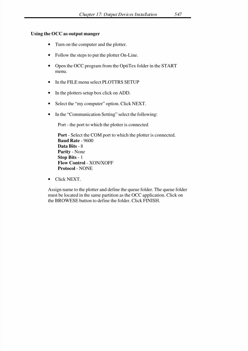
7/28/2019 OptiTex PDS User Manual
http://slidepdf.com/reader/full/optitex-pds-user-manual 568/727
Chapter 17: Output Devices Installation 547
Using the OCC as output manger
• Turn on the computer and the plotter.
• Follow the steps to put the plotter On-Line.
• Open the OCC program from the OptiTex folder in the STARTmenu.
• In the FILE menu select PLOTTRS SETUP
• In the plotters setup box click on ADD.
• Select the “my computer” option. Click NEXT.
• In the “Communication Setting” select the following:
Port - the port to which the plotter is connected
Port - Select the COM port to which the plotter is connected.
Baud Rate - 9600
Data Bits - 8
Parity - None
Stop Bits - 1
Flow Control - XON/XOFF
Protocol - NONE
• Click NEXT.
Assign name to the plotter and define the queue folder. The queue folder
must be located in the same partition as the OCC application. Click onthe BROWESE button to define the folder. Click FINISH.

7/28/2019 OptiTex PDS User Manual
http://slidepdf.com/reader/full/optitex-pds-user-manual 569/727
Digitize, PDS & Grade Manual548
! Note: Windows NT or 2000 will share the plotter to use to other users and
computers automatically. Using other operation system needs to
share the plotter manually, using the windows explorer.
• Click CLOSE to confirm the plotter installation.
• Close or minimize the OCC window.
Configuring the SGS programs
Plotter Setup
The Plotter Setup command in SGS Grade, PDS, and Mark is used to select
the location of the OutMan.ini file and the plotter to be used.
! Note: To access the Plot command, there must be a piece in the working
area.
• Place a pattern on the working area.
• From the FILE menu, choose the PLOT command
• Check the Use Output Manager field.
• Select the output manger that you using.
• For Outman users: Put the correct Outman.ini Path and plotternumber in the OUTMAN MANAGER field. Select OK.
• Click OK.
Plot
• From the FILE menu choose PLOT. The Plot dialog box willdisplay.

7/28/2019 OptiTex PDS User Manual
http://slidepdf.com/reader/full/optitex-pds-user-manual 570/727
Chapter 17: Output Devices Installation 549
! Note: To access the Plot command, there must be a piece in the working
area.
Use Output Manager - This option must be enabled to send a plot to the
plotter.
Alert on Start, Alert on End, Remove on End, Copies. - These settings areoptional. For detailed information on each of these options refer to the Plotting
chapter of the user’s manual, or the plotting tutorial.
Page Format - Set to Fixed Scale.
Options - Set to Plot Continuous.
Scale Factor - Set to X=1, Y=1.
Plotter Setting - Shows the Plotter language and the Frame or Page size.
• Select the Setup button to configure plotter language and frame size.The Plot Setting dialog box will display.
Plot Setting
Name - Shows the name of the plotter - Pltr1, Pltr2, etc. The plotter numberdepends on how many plotters were identified during the SGS software
installation process.
Format - Plotter Language. Set to HPGL/2.
Device Options
(0,0) in Page Center and Manual Page Replace – both are disabled
(unchecked).

7/28/2019 OptiTex PDS User Manual
http://slidepdf.com/reader/full/optitex-pds-user-manual 571/727
Digitize, PDS & Grade Manual550
Pens - Set to 1.
Font Options
Use Plotter’s Built-in Font - Should be enabled (checked).
Plotter Font File - Should show the Plot-eng.fnt file and its directory. If nofont file is shown, select Browse to locate the file.
Default Font Size - This setting determines the size of the text on the header
of the plot.
Gap After Plotting - This is the amount of space left between completed
plots. It is advisable to leave some space between completed plots.
Minimal Cut/Plot Line - .008
Min. Plot Spline Segment - This setting determines the smallest spline or arcto be cut as a spline or arc. This setting is not important for setup but may beadjusted later to improve the speed or quality of plots. For now set at .008
Plotter Page Size
X - The X value is the marker length. It should be set to larger than the lengthof your longest expected marker. However, this setting may be adjusted for
unusually long markers.
Y - The Y value should always be set to 35.5 inches (maximum plot width.)
7/28/2019 OptiTex PDS User Manual
http://slidepdf.com/reader/full/optitex-pds-user-manual 572/727
Chapter 17: Output Devices Installation 551
! Note: This is the Frame Size of the plotter which means that the amount of
paper the plotter feeds and tracks at one time is 35.5 inches. There is
no way to adjust the frame size in the software or on the plotter. If this
setting is set incorrectly, the plotter will either plot incorrectly or not
plot at all.
• Click OK to exit the Plotter Setup dialog box. The pieces on theworking area will be sent to print on the plotter.
Hewlett Packard 750C Ink Jet Plotter
Connecting the plotter
• Turn off the computer.
• Connect the plotter to a serial port on the computer. If your HP Ink
Jet only came with a parallel cable, it will be necessary to order an
RS232 serial cable from Hewlett Packard or from your plotterdistributor. A generic cable will not work. Your plot files will notplot on the HP Ink Jet unless you are using a cable from Hewlett
Packard.
! Tip: Serial ports are usually referred to as COM ports and can be identified
as COM1, COM2, COM3 or COM4.
! Note: Any serial port can be used. However, keep in mind that on many
computers COM ports 1 and 3 share the same IRQ (Interrupt
Request), and COM ports 2 and 4 share the same IRQ. If you have
more than 3 serial devices you may need to change the IRQ setting for one of the COM ports to avoid an IRQ conflict. For detailed
information on IRQ settings refer to the DOS and Windows manuals
for your system.
• Turn on the computer and the plotter.
7/28/2019 OptiTex PDS User Manual
http://slidepdf.com/reader/full/optitex-pds-user-manual 573/727
Digitize, PDS & Grade Manual552
• Be sure that the Page format in the HP750C Menu is set to InkedArea. Please see attached diagram from the HP 750C Quick
Reference Guide.
Using the Outman as output manger:
• From the START menu click on the OUTMAN in the OptiTex 8folder.
• From the OPTIONS menu, choose WORKING UNITS. Theworking units dialog box will display.
• Choose the appropriate setting.
• Click OK.
• From the OPTIONS menu, choose COMMUNICATION. The
Communication dialog box will display.
Port Options
Port = Select the COM port to which the plotter is connected.
Baud Rate = 9600
Data Bits = 8
Parity = None
Stop Bits = 1
Flow Control = XON/XOFF
Protocol = NONE
Paper Size
• Click SET. The Paper on Roll dialog box will display.
• Enter the Width and Length of the paper.

7/28/2019 OptiTex PDS User Manual
http://slidepdf.com/reader/full/optitex-pds-user-manual 574/727
Chapter 17: Output Devices Installation 553
• Click OK.
! Note: If the exact length of the paper is unknown, estimate. The length of
the paper needs to be longer than the plot file that will be plotted.
• Minimize the OutMan, keeping it running. Do not close theOutman.
Configuring Qman
• From the START menu click on the QMAN in the OptiTexdirectory.
• From the FILE menu, choose WORKING UNITS.
• Select the appropriate working units. The selection should matchthe working units that were set in the SGS Plot setup dialog box.
• From the FILE menu, choose OPTIONS. The OutMan Setup dialogbox will display.
The OutMan path and filename in the File Name box must be the same asspecified in the Plot Setup. If it is not:
• Select the Outman.ini path specified in the Plot Setup from the listof available drive/directories on the right.
• Click OK.
• Minimize the QMan keeping it running. Do not close the Qman.

7/28/2019 OptiTex PDS User Manual
http://slidepdf.com/reader/full/optitex-pds-user-manual 575/727
Digitize, PDS & Grade Manual554
Using the OCC as output manger
• Turn on the computer and the plotter.
• Follow the steps to put the plotter On-Line.
• Open the OCC program from the OptiTex folder in the STARTmenu.
• In the FILE menu select PLOTTRS SETUP
• In the plotters setup box click on ADD.
• Select the “my computer” option. Click NEXT.
• In the “Communication Setting” select the following:
Port = Select the COM port to which the plotter is connected.Baud Rate = 9600
Data Bits = 8
Parity = None
Stop Bits = 1
Flow Control = XON/XOFF
Protocol = NONE
• Click NEXT.
• Assign name to the plotter and define the queue folder. The queue
folder must be located in the same partition as the OCC application.Click on the BROWESE button to define the folder. Click FINISH.
7/28/2019 OptiTex PDS User Manual
http://slidepdf.com/reader/full/optitex-pds-user-manual 576/727
Chapter 17: Output Devices Installation 555
! Note: Windows NT or 2000 will share the plotter to use to other users and
computers automatically. Using other operation system needs to
share the plotter manually, using the windows explorer.
• Click CLOSE to confirm the plotter installation.
• Close or minimize the OCC window.
Configuring the SGS programs
Configuring the plotter through the SGS programs involves selecting a plotter,
configuring the plotter, and configuring the OutMan and the QMan. This
document gives basic settings and configuration instructions used for HP 750plotters. For a detailed description of the plotting options, refer to the Plotting
section of the SGS Grade, Mark, or PDS manual. Also, refer to the plotting
tutorial located at the front of each manual.
Plotter Setup
The Plotter Setup command in SGS Grade, PDS, and Mark is used to select
the location of the OutMan.ini file and the plotter to be used.
! Note: To access the Plot command, there must be a piece in the working
area.
• From the FILE menu, choose PLOT command.
• Check the “USE OUTPUT MANGER” options.
• Select the Output manger to use.
• For OutMan users: browse to locate the outman.ini file. And enterthe plotter number.

7/28/2019 OptiTex PDS User Manual
http://slidepdf.com/reader/full/optitex-pds-user-manual 577/727
Digitize, PDS & Grade Manual556
Plot
• From the FILE menu choose PLOT. The Plot dialog box willdisplay.
! Note: To access the Plot command, there must be a piece in the workingarea.
Output Manager
Use - This option must be enabled to send a plot to the plotter.
Alert on Start, Alert on End, Remove on End, Copies. - These settings areoptional. For detailed information on each of these options refer to the Plotting
chapter of the user’s manual, or the plotting tutorial.
Page Format - Set to Fixed Scale.
Options - Set to Plot Continuous.
Scale Factor - Set to X=1, Y=1.
Plotter Setting - Shows the Plotter language and the Frame or Page size.
• Select the Setup button to configure plotter language and frame size.The Plot Setting dialog box will display.
Plot Setting
Name - Shows the name of the plotter - Pltr1, Pltr2, etc. The plotter numberdepends on how many plotters were identified during the SGS software
installation process.
Format - Plotter Language. Set to HPGL/2.

7/28/2019 OptiTex PDS User Manual
http://slidepdf.com/reader/full/optitex-pds-user-manual 578/727
Chapter 17: Output Devices Installation 557
Device Options
(0,0) in Page Center and Manual Page Replace – both are disabled
(unchecked).
Pens - Set to 1.
Font Options
Use Plotter’s Built-in Font - Should be disabled (unchecked).
Plotter Font File - Should show the Plot-eng.fnt file and its directory. If no
font file is shown, select Browse to locate the file.
Default Font Size - This setting determines the size of the text on the header
of the plot.
Gap After Plotting - This is the amount of space left between completedplots. It is advisable to leave some space between completed plots.
Minimal Cut/Plot Line - .008
Min. Plot Spline Segment - This setting determines the smallest spline or arc
to be cut as a spline or arc. This setting is not important for setup but may beadjusted later to improve the speed or quality of plots. For now set at .008
Plotter Page Size
X - The X value is the marker length. It should be set to larger than the length
of your longest expected marker. However, this setting may be adjusted forunusually long markers.
Y - The Y value should always be set to 35.5 inches (maximum plot width.)

7/28/2019 OptiTex PDS User Manual
http://slidepdf.com/reader/full/optitex-pds-user-manual 579/727
Digitize, PDS & Grade Manual558
! Note: This is the Frame Size of the plotter which means that the amount of
paper the plotter feeds and tracks at one time is 35.5 inches. There is
no way to adjust the frame size in the software or on the plotter. If this
setting is set incorrectly, the plotter will either plot incorrectly or not
plot at all.
• Click OK to exit the Plotter Setup dialog box.
• Click OK in the Plot dialog box. The settings will be saved but theplot will not be sent because the OutMan and QMan have not been
setup.
Troubleshooting for the HP Ink Jet 750C
Make sure the I/O settings on the plotter have been setup. For instructions,
refer to the HP user manual. Settings should correspond with the port options
used in SGS software when configuring the OutMan. (See section,
“Configuring Outman” under “Communication.”)
Be sure that the Page format in the HP750C Menu is set to Inked Area. Please
see attached diagram from the HP 750C Quick Reference Guide.

7/28/2019 OptiTex PDS User Manual
http://slidepdf.com/reader/full/optitex-pds-user-manual 580/727
Chapter 17: Output Devices Installation 559
From the HP750C Quick Reference Guide
Front-Panel Menu (On Plotter) Structure
Page Format -> Size -> Oversize -> Inked Area
7/28/2019 OptiTex PDS User Manual
http://slidepdf.com/reader/full/optitex-pds-user-manual 581/727
Digitize, PDS & Grade Manual560
Configuring the Hewlett Packard Draftmaster II Plotter
The HP Draftmaster II (model #7596A) plotter will not plot more than one
frame. A frame is 46 inches long.
Connecting the plotter
• Turn your computer off.
• Connect the plotter to a serial port on the computer.
! Tip: Serial ports are usually referred to as COM ports and can be identified
as COM1, COM2, COM3 or COM4.
! Note: Any serial port can be used however, keep in mind that on many
computers COM ports 1 and 3 share the same IRQ (Interrupt
Request), and COM ports 2 and 4 share the same IRQ. If you have
more than 3 serial devices you may need to change the IRQ setting
for one of the COM ports to avoid an IRQ conflict. For detailed
information on IRQ settings refer to the DOS and Windows manuals
for your system.
• Turn the computer on.
• Turn the plotter on.
7/28/2019 OptiTex PDS User Manual
http://slidepdf.com/reader/full/optitex-pds-user-manual 582/727
Chapter 17: Output Devices Installation 561
Configuring SGS Programs
Plotter Setup
! Note: To access the Plot command you must have a piece in the working
area.
• From the FILE menu choose PLOT command. The plot dialog boxwill be displayed.
• Enable the USE OUTPUT MANGER by clicking the box next tothe Use Output Manager option. A small “x” should appear in the
box.
• For OUTMAN users: locate the outman.ini file by selecting theBrowse button. Select the directory that contains the OutMan.ini
file.
• Select the Plotter number you want to assign to the HP plotter (i.e.
Pltr1, Pltr2, etc.)
• Click OK.
Plot
• From the FILE menu choose PLOT. The Plot dialog box will bedisplayed.
! Note: To access the Plot command you must have a piece in the workingarea.
Output Manager
Use - This option must be enabled to send a plot to the plotter.
7/28/2019 OptiTex PDS User Manual
http://slidepdf.com/reader/full/optitex-pds-user-manual 583/727
Digitize, PDS & Grade Manual562
Alert on Start, Alert on End, Remove on End, Copies. - These settings are
optional. For detailed information on each of these options refer to the Plotting
chapter of the user’s manual, or the plotting tutorial.
Page Format - Page format should be set to Fixed Scale.
Options -
Plot Continuous - enabled
Scale Factor - Should be set to X=1, Y=1.
Plotter Setting - Shows the Plotter language and the Frame or Page size.
• Select the Setup button to configure plotter language and frame size.The Plot Setting dialog box will be displayed.
Plot Setting
Name - Shows the name of the plotter - Pltr1, Pltr2, etc. The number of Pltr
listing depends on how many plotters you specified during your OptiTex
software installation.
Format - Plotter Language. Should be set to HPGL
Device Options
(0,0) in Page Center - enabled
Manual Page Replace - disabled.
Number of Pens - set to 1.
Font Options
Use Plotter’s Built-in Font - disabled.

7/28/2019 OptiTex PDS User Manual
http://slidepdf.com/reader/full/optitex-pds-user-manual 584/727
Chapter 17: Output Devices Installation 563
Plotter Font File - Should show the Plot-eng.fnt file and its directory. If no
font file is shown, select Browse to locate the file.
Default Font Size - This setting determines the size of the text on the plot.
! Note: This setting overrides the plot font settings specified elsewhere in the
program.
Gap After Plotting - This is the amount of space left between completed
plots. It is advisable to leave some space between completed plots to enablecutting between the plots. (Commonly set to 4”)
Minimal Cut/Plot Line - .008
Min. Plot Spline Segment - This setting determines the smallest spline or arc
to be cut as a spline or arc. This setting is not important for setup but may be
adjusted later to improve the speed or quality of plots. For now set at .008
Plotter Page Size
X - The X value should always be set to 46 inches. (Max frame size)
Y - The Y value should always be set to 34.5 inches. (Maximum plot width)
! Note: This is the Frame Size of the plotter meaning this is the amount of
paper the plotter feeds and tracks at one time. There is no way to
adjust the frame size in the software or on the plotter. If this setting is
set to anything else, the plotter will either plot incorrectly or not plot
at all.
• Click OK to exit the Plotter Setup dialog box.
• Click OK in the Plot dialog box. The settings will be saved but theplot will not be sent because the OutMan and QMan have not been
setup.
7/28/2019 OptiTex PDS User Manual
http://slidepdf.com/reader/full/optitex-pds-user-manual 585/727
Digitize, PDS & Grade Manual564
Configuring the output manger
Using the Outman as output manger
• Open the OutMan from the START menu/OptiTex/output control.
• Working Units - From the OPTIONS menu choose WORKINGUNITS. The working units dialog box will be displayed.
• Choose the setting you wish to use.
• Click OK.
• From the OPTIONS menu choose COMMUNICATION. TheCommunication dialog box will be displayed.
Communication
Port Options
Port = Select the COM port you have the plotter connected to.
Baud Rate = 9600
Data Bits = 8
Parity = None
Stop Bits = 1
Flow Control = XON/XOFF
Protocol = NONE
Paper Size
• Click SET. The Paper on Roll dialog box will be displayed.
• Enter the Width and Length of the paper you are using.
• Click OK.

7/28/2019 OptiTex PDS User Manual
http://slidepdf.com/reader/full/optitex-pds-user-manual 586/727
Chapter 17: Output Devices Installation 565
! Note: If you are using a roll of paper and don’t know the exact length,
estimate. The length of the paper needs to be longer than the plot you
wish to send.
• Minimize the OutMan, keeping it running.
Configuring Qman
• Open the QMan by double clicking on the icon at START manu/ OptiTex 8 / output manger.
Working Units
• From the FILE menu choose WORKING UNITS.
• Select the same setting you selected in the OptiTex plot setup.
OutMan Path Setup
• From the OPTIONS menu choose OUTMAN PATH. The OutManSetup dialog box will be displayed.
• The OutMan path and filename in the File Name box must be thesame as specified in the Plot Setup. If it is not:
• Select the Outman.ini path specified in the Plot Setup from the listof available drive/directories on the right.
• Click OK.
• Minimize the QMan, keeping it running.
Using the OCC as output manger
• Turn off the computer.

7/28/2019 OptiTex PDS User Manual
http://slidepdf.com/reader/full/optitex-pds-user-manual 587/727
Digitize, PDS & Grade Manual566
• Connect the plotter cable to a serial port on the computer, preferablyCOM1 or COM2.
! Note: Serial ports are needed to run the digitizer and plotter at the same
time. The digitizer may not be on COM2 while the plotter is on COM4
or visa versa. COM2 and COM4 may be used with a mouse and
digitizer, digitizer and modem, plotter and a mouse, or plotter and
modem.
• Turn on the computer and the plotter.
• Follow the steps to put the plotter On-Line.
• Open the OCC program from START menu, OptiTex folder.
• In the FILE menu select PLOTTRS SETUP
• In the plotters setup box click on ADD.
• Select the “my computer” option. Click NEXT.
• In the “Communication Setting” select the following:
Port = Select the COM port you have the plotter connected to.
Baud Rate = 9600
Data Bits = 8
Parity = None
Stop Bits = 1
Flow Control = XON/XOFFProtocol = NONE
• Click NEXT.

7/28/2019 OptiTex PDS User Manual
http://slidepdf.com/reader/full/optitex-pds-user-manual 588/727
Chapter 17: Output Devices Installation 567
• Assign name to the plotter and define the queue folder. The queuefolder must be located in the same partition as the OCC application.
Click on the BROWESE button to define the folder. Click FINISH.
! Note: Windows NT or 2000 will share the plotter to use to other users and
computers automatically. Using other operation system needs to
share the plotter manually, using the windows explorer.
• Click CLOSE to confirm the plotter installation.
• Close or minimize the OCC window.

7/28/2019 OptiTex PDS User Manual
http://slidepdf.com/reader/full/optitex-pds-user-manual 589/727
Digitize, PDS & Grade Manual568
Ioline 28 Plotter
Connecting the plotter
• Turn off the computer.
• Connect the plotter to a serial port on the computer.
! Tip: Serial ports are usually identified as COM ports and can be identified
as COM1, COM2, COM3 or COM4.
! Note: Any serial port can be used. However, keep in mind that on many
computers COM Ports 1 and 3 share the same IRQ, and COM ports 2
and 4 share the same IRQ. If you have more than 3 serial devices you
may need to change the IRQ setting for one of the COM ports. For
detailed information on IRQ settings refer to the DOS and Windows
manuals for your system.
• Turn on the computer and the plotter.
Install the Ioline software
• Put the Ioline diskette into the floppy drive.
• From the START menu, select RUN.
• Type SETUP: A.
• Select OK or press Enter on the keyboard.
• Follow the on-screen instructions for installation and setup.
7/28/2019 OptiTex PDS User Manual
http://slidepdf.com/reader/full/optitex-pds-user-manual 590/727
Chapter 17: Output Devices Installation 569
! Note: For detailed instructions on installing the Ioline software, refer to the
Installation chapter of the Ioline user’s manual.
Test Plot
Once the Plotter and software have been installed and configured, send a test
plot to the plotter. The Ioline Control Center software includes a couple testplot files. The “Send Plot File” command is located in the FILE menu. For
instructions on sending a test file to the Ioline 28, refer to the Ioline user’s
manual.
Calibration Plot
Once a test plot has been successfully plotted indicating that the plotter has
been configured properly in the Ioline software, the plot may be calibrated.Calibrating the plot involves plotting a pre-determined size square, measuring
the actual plot and entering the values into the Ioline Calibration program. The
Ioline software makes the necessary corrections and sends the settings to theplotter. The CALIBRATE PLOTTER command is located in theCALIBRATE menu. For detailed instructions on running the calibration
program, refer to the Ioline user’s manual.
Configuring SGS Programs for the Ioline
Plot Setup
! Note: To access the Plot command, there must a piece in the working area.
• From the FILE menu choose PLOT command. The plot dialog boxwill be displayed.
• Enable the USE OUTPUT MANGER by clicking the box next tothe Use Output Manager option. A small “x” should appear in the
box.

7/28/2019 OptiTex PDS User Manual
http://slidepdf.com/reader/full/optitex-pds-user-manual 591/727
Digitize, PDS & Grade Manual570
• For OUTMAN users: locate the outman.ini file by selecting theBrowse button. Select the directory that contains the OutMan.ini
file.
• Select the Plotter number you want to assign to the HP plotter (i.e.
Pltr1, Pltr2, etc.)
• Click OK.
Plot
• From the FILE menu choose PLOT. The “Plot” dialog box will
display.
! Note: To access the Plot command, there must be a piece in the working
area.
Output Manager
Use - This option must be enabled to send a plot to the plotter.
Alert on Start, Alert on End, Remove on End, Copies. - These settings areoptional. For detailed information on each of these options, refer to the
Plotting chapter of the manual, or the plotting tutorial.
Page Format - Set to Fixed Scale.
Options - Set to Plot Continuous.
Scale Factor - Set to X=1 Y=1.
Frame Advance After Last Frame – Checked.
Bulge Corde Error – controls curved lines. The closer the setting to 0, the
truer the curve. However, as this setting gets closer to 0, the pen also moves
7/28/2019 OptiTex PDS User Manual
http://slidepdf.com/reader/full/optitex-pds-user-manual 592/727
Chapter 17: Output Devices Installation 571
slower. A larger number creates a faster, less accurate curve. Use .008 inches
as a starting point and adjust this setting as necessary.
Plotter Setting - Shows the Plotter language and the Frame or Page size.
• Select the Setup button to configure plotter language and frame size.The Plot Setting dialog box will display.
Plot Setting
Name - Shows the name of the plotter - Pltr1, Pltr2, etc. The number of the
plotter depends on how many plotters were identified during SGS softwareinstallation.
Format - Plotter Language. Set to either HPGL or DMPL.
Device Options
(0,0) in Page Center - Should be disabled (unchecked).
Manual Page Replace - Should be disabled (unchecked).
Number of Pens - Set to 1.
Font Options
Use Plotter’s Built-in Font - Should be disabled (unchecked).
Plotter Font File – The Plot-eng.fnt file and its directory should be displayed.If no font file is shown, select Browse to locate the file (usually located in
C:\OptiTex).
Default Font Size - This setting determines the size of the text on the headerof the marker.

7/28/2019 OptiTex PDS User Manual
http://slidepdf.com/reader/full/optitex-pds-user-manual 593/727
Digitize, PDS & Grade Manual572
Gap After Plotting - This is the amount of space left between completed
plots. It is advisable to leave some space between completed plots.
Minimal Cut/Plot Line - This setting is not necessary for Ioline plotters.
Min. Plot Spline Segment - This setting determines the smallest spline or arc
to be cut as a spline or arc. This setting is not important for setup but may beadjusted later to improve the speed or quality of plots. The default is 0.
Plotter Page Size
Y - The Y value is the useable width of the paper (minus margins.) The factorysetting is 72 inches. Adjust this setting according to the paper size you are
using.
X- The X value should always be set to 46 inches or 118 cm.
! Note: This is the Frame Size of the plotter which means that the amount of paper the plotter feeds and tracks at one time is 46 inches. There is no
way to adjust the frame size in the software or on the plotter. If this
setting is set incorrectly, the plotter will either plot incorrectly or not
plot at all.
• Click OK to exit the Plotter Setup dialog box.
• Click OK in the Plot dialog box. The settings will be saved but theplot will not be sent because the OutMan and QMan have not been
setup.
The SGS software has been configured. The next step is to configure the
OutMan and the Qman. The OutMan and QMan start automatically when a
plot file is sent to the plotter.
7/28/2019 OptiTex PDS User Manual
http://slidepdf.com/reader/full/optitex-pds-user-manual 594/727
Chapter 17: Output Devices Installation 573
Configuring the output manger
Use the Outman as output manger.
• Open the OutMan from the START menu/OptiTex/output control.
Working Units
From the OPTIONS menu choose WORKING UNITS. The working
units dialog box will display.
• Choose the appropriate setting.
• Click OK.
Communication
• From the OPTIONS menu, choose COMMUNICATION. The
Communication dialog box will display.
Port Options
Port = Select the COM port to which the plotter is connected.
Baud Rate = 9600Data Bits = 8
Parity = None
Stop Bits = 1
Flow = The flow settings are different for HPGL and DMPL.
HPGL
DTR/DSR = Enabled (checked)RTS/CTS = Enabled (checked)
Xon/Xoff = Disabled (unchecked)
DMPL (recommended)

7/28/2019 OptiTex PDS User Manual
http://slidepdf.com/reader/full/optitex-pds-user-manual 595/727
Digitize, PDS & Grade Manual574
DTR/DSR = Disabled (unchecked)
RTS/CTS = Disabled (unchecked)
Xon/Xoff = Enabled (checked)
Protocol = NONE.
Paper Size
• Click SET. The Paper on Roll dialog box will display.
• Enter the Width and Length of the paper.
• Click OK.
! Note: If the exact paper length is unknown, estimate. The length of the
paper needs to be longer than the file that will be plotted.
• Minimize the OutMan, keeping it running. Do not close OutMan
Configuring Qman
• Open the QMan by clicking on the icon from the output utility sub
folder in the START menu / OptiTex folder.
Working Units
• From the FILE menu, choose WORKING UNITS.
• Select the appropriate units. The selection should match theworking units set in the SGS plot dialog box.

7/28/2019 OptiTex PDS User Manual
http://slidepdf.com/reader/full/optitex-pds-user-manual 596/727
Chapter 17: Output Devices Installation 575
OutMan Path Setup
• From the OPTION menu, choose OUTMAN PATH. The OutManSetup dialog box will display.
The OutMan path and filename in the File Name box must be thesame as specified in the Plot Setup. If it is not: Select the
Outman.ini path specified in the Plot Setup from the list of
available drive/directories on the right.
• Click OK.
• Minimize the QMan keeping it running. Do not close Qman.
Hints
If the plotter does not plot, check the file name length. It should be limited to
8 alphanumeric characters.
Using the OCC as output manger
• Turn off the computer.
• Connect the plotter cable to a serial port on the computer, preferablyCOM1 or COM2.
! Note: Serial ports are needed to run the digitizer and plotter at the same
time. The digitizer may not be on COM2 while the plotter is on COM4
or visa versa. COM2 and COM4 may be used with a mouse and digitizer, digitizer and modem, plotter and a mouse, or plotter and
modem.
• Turn on the computer and the plotter.

7/28/2019 OptiTex PDS User Manual
http://slidepdf.com/reader/full/optitex-pds-user-manual 597/727
Digitize, PDS & Grade Manual576
• Follow the steps to put the plotter On-Line.
• Open the OCC program from the OptiTex folder in the STARTmenu.
• In the FILE menu select PLOTTRS SETUP
• In the plotters setup box click on ADD.
• Select the “my computer” option. Click NEXT.
• In the “Communication Setting” select the following:
Port = Select the COM port to which the plotter is connected.
Baud Rate = 9600
Data Bits = 8
Parity = None
Stop Bits = 1Flow = The flow settings are different for HPGL and DMPL.
HPGLDTR/DSR = Enabled (checked)
RTS/CTS = Enabled (checked)Xon/Xoff = Disabled (unchecked)
DMPL (recommended)DTR/DSR = Disabled (unchecked)
RTS/CTS = Disabled (unchecked)
Xon/Xoff = Enabled (checked)Protocol = NONE.
• Click NEXT.

7/28/2019 OptiTex PDS User Manual
http://slidepdf.com/reader/full/optitex-pds-user-manual 598/727
Chapter 17: Output Devices Installation 577
• Assign name to the plotter and define the queue folder. The queuefolder must be located in the same partition as the OCC application.
Click on the BROWESE button to define the folder. Click FINISH.
! Note: Windows NT or 2000 will share the plotter to use to other users and
computers automatically. Using other operation system needs to
share the plotter manually, using the windows explorer.
• Click CLOSE to confirm the plotter installation.
• Close or minimize the OCC window.
7/28/2019 OptiTex PDS User Manual
http://slidepdf.com/reader/full/optitex-pds-user-manual 599/727
Digitize, PDS & Grade Manual578
Ioline 600 Plotter
Connecting the plotter
• Turn off the computer.
• Connect the plotter to a serial port on the computer.
! Tip: Serial ports are usually identified as COM ports and can be identified
as COM1, COM2, COM3 or COM4.
! Note: Any serial port can be used. However, keep in mind that on many
computers COM Ports 1 and 3 share the same IRQ and COM ports 2
and 4 share the same IRQ. If you have more than 3 serial devices you
may need to change the IRQ setting for one of the COM ports. For
detailed information on IRQ settings refer to the DOS and Windows
manuals for your system.
• Turn on the computer and the plotter.
Install the Ioline software
• Put the Ioline diskette into the floppy drive.
• From the START menu, select RUN.
• Type SETUP: A.
• Select OK or press Enter on the keyboard.
• Follow the on-screen instructions for installation and setup.

7/28/2019 OptiTex PDS User Manual
http://slidepdf.com/reader/full/optitex-pds-user-manual 600/727
Chapter 17: Output Devices Installation 579
! Note: For detailed instructions on installing the Ioline software, refer to the
Installation chapter of the Ioline user’s manual.
Test Plot
Once the Plotter and software have been installed and configured, send a test
plot to the plotter. The Ioline Control Center software includes a couple testplot files. The “Send Plot File” command is located in the FILE menu. For
instructions on sending a test file to the Ioline 600, refer to the Ioline user’s
manual.
Calibration Plot
Once a test plot has been successfully plotted indicating that the plotter has
been configured properly in the Ioline software, the plot may be calibrated.Calibrating the plot involves plotting a pre-determined size square, measuring
the actual plot and entering the values into the Ioline Calibration program. The
Ioline software makes the necessary corrections and sends the settings to theplotter. The CALIBRATE PLOTTER command is located in theCALIBRATE menu. For detailed instructions on running the calibration
program, refer to the Ioline user’s manual.
Configuring SGS Programs for the Ioline
Plot Setup
! Note: To access the Plot command, there must a piece in the working area.
• From the FILE menu choose PLOT command. The plot dialog boxwill be displayed.
• Enable the USE OUTPUT MANGER by clicking the box next tothe Use Output Manager option. A small “x” should appear in the
box.

7/28/2019 OptiTex PDS User Manual
http://slidepdf.com/reader/full/optitex-pds-user-manual 601/727
Digitize, PDS & Grade Manual580
• For OutMan users: locate the outman.ini file by selecting theBrowse button. Select the directory that contains the OutMan.ini
file.
• Select the Plotter number you want to assign to the HP plotter (i.e.
Pltr1, Pltr2, etc.)
• Click OK.
Plot
• From the FILE menu choose PLOT. The “Plot” dialog box will
display.
! Note: To access the Plot command, there must be a piece in the working
area.
Output Manager
Use - This option must be enabled to send a plot to the plotter.
Alert on Start, Alert on End, Remove on End, Copies. - These settings areoptional. For detailed information on each of these options, refer to the
Plotting chapter of the manual, or the plotting tutorial.
Page Format - Set to Fixed Scale.
Options - Set to Plot Continuous.
Scale Factor - Set to X=1 Y=1.
Frame Advance After Last Frame – Checked.
Bulge Cord Error – controls curved lines. The closer the setting to 0, the
truer the curve. However, as this setting gets closer to 0, the pen also moves

7/28/2019 OptiTex PDS User Manual
http://slidepdf.com/reader/full/optitex-pds-user-manual 602/727
Chapter 17: Output Devices Installation 581
slower. A larger number creates a faster, less accurate curve. Use .008 inches
as a starting point and adjust this setting as necessary.
Plotter Setting - Shows the Plotter language and the Frame or Page size.
• Select the Setup button to configure plotter language and frame size.The Plot Setting dialog box will display.
Plot Setting
Name - Shows the name of the plotter - Pltr1, Pltr2, etc. The number of the
plotter depends on how many plotters were identified during SGS software
installation.
Format - Plotter Language. Set to either HPGL or DMPL.
Device Options
(0,0) in Page Center - Should be disabled (unchecked).
Manual Page Replace - Should be disabled (unchecked).
Number of Pens - Set to 1.
Font Options
Use Plotter’s Built-in Font - Should be disabled (unchecked).
Plotter Font File – The Plot-eng.fnt file and its directory should be displayed.
If no font file is shown, select Browse to locate the file (usually located inC:\OptiTex).
Default Font Size - This setting determines the size of the text on the header
of the marker.
7/28/2019 OptiTex PDS User Manual
http://slidepdf.com/reader/full/optitex-pds-user-manual 603/727
Digitize, PDS & Grade Manual582
Gap After Plotting - This is the amount of space left between completed
plots. It is advisable to leave some space between completed plots.
Minimal Cut/Plot Line - This setting is not necessary for Ioline plotters.
Min. Plot Spline Segment - This setting determines the smallest spline or arc
to be cut as a spline or arc. This setting is not important for setup but may beadjusted later to improve the speed or quality of plots. The default is 0.
Plotter Page Size
Y - The Y value is the useable width of the paper (minus margins.) The factorysetting is 72 inches. Adjust this setting according to the paper size you are
using.
X- The X value should always be set to 46 inches or 118 cm.
! Note: This is the Frame Size of the plotter which means that the amount of paper the plotter feeds and tracks at one time is 46 inches. There is no
way to adjust the frame size in the software or on the plotter. If this
setting is set incorrectly, the plotter will either plot incorrectly or not
plot at all.
• Click OK to exit the Plotter Setup dialog box.
• Click OK in the Plot dialog box. The settings will be saved but theplot will not be sent because the OutMan and QMan have not been
setup.

7/28/2019 OptiTex PDS User Manual
http://slidepdf.com/reader/full/optitex-pds-user-manual 604/727
Chapter 17: Output Devices Installation 583
Configuring the output manger
Using the Outman as output manger.
• Open the OutMan from the START menu/OptiTex/output control.
Working Units
From the OPTIONS menu choose WORKING UNITS. The working
units dialog box will display.
• Choose the appropriate setting.
• Click OK.
Communication
• From the OPTIONS menu, choose COMMUNICATION. The
Communication dialog box will display.
Port Options
Port = Select the COM port to which the plotter is connected.
Baud Rate = 9600Data Bits = 8
Parity = None
Stop Bits = 1
Flow = The flow settings are different for HPGL and DMPL.
HPGL
DTR/DSR = Enabled (checked)RTS/CTS = Enabled (checked)
Xon/Xoff = Disabled (unchecked)
DMPL (recommended)
DTR/DSR = Disabled (unchecked)

7/28/2019 OptiTex PDS User Manual
http://slidepdf.com/reader/full/optitex-pds-user-manual 605/727
Digitize, PDS & Grade Manual584
RTS/CTS = Disabled (unchecked)
Xon/Xoff = Enabled (checked)
Protocol = NONE.
Paper Size
• Click SET. The Paper on Roll dialog box will display.
• Enter the Width and Length of the paper.
• Click OK.
! Note: If the exact paper length is unknown, estimate. The length of the
paper needs to be longer than the file that will be plotted.
• Minimize the OutMan, keeping it running. Do not close OutMan
Configuring Qman
• Open the QMan by clicking on the icon from the output utility subfolder in the START menu / OptiTex folder/ Output Control
Working Units
• From the FILE menu, choose WORKING UNITS.
• Select the appropriate units. The selection should match theworking units set in the SGS plot dialog box.
OutMan Path Setup
• From the OPTION menu, choose OUTMAN PATH. The OutManSetup dialog box will display.

7/28/2019 OptiTex PDS User Manual
http://slidepdf.com/reader/full/optitex-pds-user-manual 606/727

7/28/2019 OptiTex PDS User Manual
http://slidepdf.com/reader/full/optitex-pds-user-manual 607/727
Digitize, PDS & Grade Manual586
• In the plotters setup box click on ADD.
• Select the “my computer” option. Click NEXT.
• In the “Communication Setting” select the following:
Port = Select the COM port to which the plotter is connected.
Baud Rate = 9600
Data Bits = 8
Parity = None
Stop Bits = 1
Flow = The flow settings are different for HPGL and DMPL.
HPGL
DTR/DSR = Enabled (checked)
RTS/CTS = Enabled (checked)Xon/Xoff = Disabled (unchecked)
DMPL (recommended)DTR/DSR = Disabled (unchecked)
RTS/CTS = Disabled (unchecked)
Xon/Xoff = Enabled (checked)
Protocol = NONE.
• Click NEXT.
• Assign name to the plotter and define the queue folder. The queuefolder must be located in the same partition as the OCC application.
Click on the BROWESE button to define the folder. Click FINISH.

7/28/2019 OptiTex PDS User Manual
http://slidepdf.com/reader/full/optitex-pds-user-manual 608/727
Chapter 17: Output Devices Installation 587
! Note: Windows NT or 2000 will share the plotter to use to other users and
computers automatically. Using other operation system needs to
share the plotter manually, using the windows explorer.
• Click CLOSE to confirm the plotter installation.
• Close or minimize the OCC window.
7/28/2019 OptiTex PDS User Manual
http://slidepdf.com/reader/full/optitex-pds-user-manual 609/727
Digitize, PDS & Grade Manual588
Ioline Studio Plotter
Connecting the plotter
• Turn off the computer.
• Connect the plotter to a serial port on the computer.
! Tip: Serial ports are usually identified as COM ports and can be identified
as COM1, COM2, COM3 or COM4.
! Note: Any serial port can be used. However, keep in mind that on many
computers COM Ports 1 and 3 share the same IRQ, and COM ports 2
and 4 share the same IRQ. If you have more than 3 serial devices you
may need to change the IRQ setting for one of the COM ports. For
detailed information on IRQ settings refer to the DOS and Windows
manuals for your system.
• Turn on the computer and the plotter.
Install the Ioline software
• Put the Ioline diskette into the floppy drive.
• From the START menu, select RUN.
• Type SETUP: A.
• Select OK or press Enter on the keyboard.
• Follow the on-screen instructions for installation and setup.

7/28/2019 OptiTex PDS User Manual
http://slidepdf.com/reader/full/optitex-pds-user-manual 610/727
Chapter 17: Output Devices Installation 589
! Note: For detailed instructions on installing the Ioline software, refer to the
Installation chapter of the Ioline user’s manual.
Test Plot
Once the Plotter and software have been installed and configured, send a test
plot to the plotter. The Ioline Control Center software includes a couple testplot files. The “Send Plot File” command is located in the FILE menu. For
instructions on sending a test file to the Ioline 600, refer to the Ioline user’s
manual.
Calibration Plot
Once a test plot has been successfully plotted indicating that the plotter has
been configured properly in the Ioline software, the plot may be calibrated.Calibrating the plot involves plotting a pre-determined size square, measuring
the actual plot and entering the values into the Ioline Calibration program. The
Ioline software makes the necessary corrections and sends the settings to theplotter. The CALIBRATE PLOTTER command is located in theCALIBRATE menu. For detailed instructions on running the calibration
program, refer to the Ioline user’s manual.
Configuring SGS Programs for the Ioline
Plot Setup
! Note: To access the Plot command, there must a piece in the working area.
• From the FILE menu, choose PLOT. The Plot dialog box willdisplay.
• Enable the “Use Output Manager”. A small “x” should appear in thebox.
7/28/2019 OptiTex PDS User Manual
http://slidepdf.com/reader/full/optitex-pds-user-manual 611/727
Digitize, PDS & Grade Manual590
• For OutMan users: Select the directory that contains the OutMan.ini(usually C:\Optitex) by clicking the Browse. Select the Plotter
number to be assigned to the Ioline.
• Click OK.
Plot
• From the FILE menu choose PLOT. The “Plot” dialog box willdisplay.
! Note: To access the Plot command, there must be a piece in the working
area.
Output Manager
Use - This option must be enabled to send a plot to the plotter.
Alert on Start, Alert on End, Remove on End, Copies. - These settings are
optional. For detailed information on each of these options, refer to the
Plotting chapter of the manual, or the plotting tutorial.
Page Format - Set to Fixed Scale.
Options - Set to Plot Continuous.
Scale Factor - Set to X=1 Y=1.
Frame Advance After Last Frame – Checked.
Bulge Cord Error – controls curved lines. The closer the setting to 0, the
truer the curve. However, as this setting gets closer to 0, the pen also moves
slower. A larger number creates a faster, less accurate curve. Use .008 inchesas a starting point and adjust this setting as necessary.

7/28/2019 OptiTex PDS User Manual
http://slidepdf.com/reader/full/optitex-pds-user-manual 612/727
Chapter 17: Output Devices Installation 591
Plotter Setting - Shows the Plotter language and the Frame or Page size.
• Select the Setup button to configure plotter language and frame size.The Plot Setting dialog box will display.
Plot Setting
Name - Shows the name of the plotter - Pltr1, Pltr2, etc. The number of the
plotter depends on how many plotters were identified during SGS software
installation.
Format - Plotter Language. Set to either HPGL or DMPL.
Device Options
(0,0) In Page Center - Should be disabled (unchecked).
Manual Page Replace - Should be disabled (unchecked).
Number of Pens - Set to 1.
Font Options
Use Plotter’s Built-in Font - Should be disabled (unchecked).
Plotter Font File – The Plot-eng.fnt file and its directory should be displayed.If no font file is shown, select Browse to locate the file (usually located in
C:\OptiTex).
Default Font Size - This setting determines the size of the text on the headerof the marker.
Gap After Plotting - This is the amount of space left between completed
plots. It is advisable to leave some space between completed plots.

7/28/2019 OptiTex PDS User Manual
http://slidepdf.com/reader/full/optitex-pds-user-manual 613/727
Digitize, PDS & Grade Manual592
Minimal Cut/Plot Line - This setting is not necessary for Ioline plotters.
Min. Plot Spline Segment - This setting determines the smallest spline or arc
to be cut as a spline or arc. This setting is not important for setup but may be
adjusted later to improve the speed or quality of plots. The default is 0.
Plotter Page Size
Y – The Y value should be 39.5 inches (the maximum plotting & cutting
width).
X – The X value should be 46 inches (the plotter frame size).
! Note: This is the Frame Size of the plotter which means that the amount of
paper the plotter feeds and tracks at one time is 46 inches. There is no
way to adjust the frame size in the software or on the plotter. If this
setting is set incorrectly, the plotter will either plot incorrectly or not
plot at all.
• Click OK to exit the Plotter Setup dialog box.
• 4. Click OK in the Plot dialog box. The settings will be savedbut the plot will not be sent because the OutMan and Qman were
not set.
Configuring the output manger
Using the OutMan as output manger
• In the START menu, click on the OutMan icon at the OptiTex \ OUTPUT CONTROL folder.
• From the OPTIONS menu choose WORKING UNITS. Theworking units dialog box will display.

7/28/2019 OptiTex PDS User Manual
http://slidepdf.com/reader/full/optitex-pds-user-manual 614/727
Chapter 17: Output Devices Installation 593
• Choose the appropriate setting.
• Click OK.
Communication
• From the OPTIONS menu, choose COMMUNICATION. TheCommunication dialog box will display.
Port Options
Port = Select the COM port to which the plotter is connected.
Baud Rate = 9600
Data Bits = 8
Parity = None
Stop Bits = 1
Flow = The flow settings are different for HPGL and DMPL.
HPGLDTR/DSR = Enabled (checked)
RTS/CTS = Enabled (checked)Xon/Xoff = Disabled (unchecked)
DMPL (recommended)
DTR/DSR = Disabled (unchecked)RTS/CTS = Disabled (unchecked)
Xon/Xoff = Enabled (checked)
Protocol = NONE.
Paper Size
• Click SET. The Paper on Roll dialog box will display.
• Enter the Width and Length of the paper.

7/28/2019 OptiTex PDS User Manual
http://slidepdf.com/reader/full/optitex-pds-user-manual 615/727
Digitize, PDS & Grade Manual594
• Click OK.
! Note: If the exact paper length is unknown, estimate. The length of the
paper needs to be longer than the file that will be plotted.
• Minimize the OutMan, keeping it running. Do not close OutMan
Configuring Qman
• Open the QMan by clicking on the icon from the Output Controlsub folder in the START menu / OptiTex folder.
Working Units
• From the FILE menu, choose WORKING UNITS.
• Select the appropriate units. The selection should match theworking units set in the SGS plot dialog box.
OutMan Path Setup
• From the OPTION menu, choose OUTMAN PATH. The OutManSetup dialog box will display.
• The OutMan path and filename in the File Name box must be thesame as specified in the Plot Setup. If it is not:
• Select the Outman.ini path specified in the Plot Setup from the listof available drive/directories on the right.
• Click OK.
• Minimize the Qman keeping it running. Do not close Qman.
7/28/2019 OptiTex PDS User Manual
http://slidepdf.com/reader/full/optitex-pds-user-manual 616/727
Chapter 17: Output Devices Installation 595
Using the OCC as output manger
• Turn off the computer.
• Connect the plotter cable to a serial port on the computer, preferably
COM1 or COM2.
! Note: Serial ports are needed to run the digitizer and plotter at the same
time. The digitizer may not be on COM2 while the plotter is on COM4
or visa versa. COM2 and COM4 may be used with a mouse and
digitizer, digitizer and modem, plotter and a mouse, or plotter and
modem.
• Turn on the computer and the plotter.
• Follow the steps to put the plotter On-Line.
• Open the OCC program from the OptiTex folder in the STARTmenu.
• In the FILE menu select PLOTTRS SETUP
• In the plotters setup box click on ADD.
• Select the “my computer” option. Click NEXT.
• In the “Communication Setting” select the following:
Port Options
Port = Select the COM port to which the plotter is connected.
Baud Rate = 9600
Data Bits = 8
Parity = None
Stop Bits = 1
7/28/2019 OptiTex PDS User Manual
http://slidepdf.com/reader/full/optitex-pds-user-manual 617/727
Digitize, PDS & Grade Manual596
Flow = The flow settings are different for HPGL and DMPL.
HPGLDTR/DSR = Enabled (checked)
RTS/CTS = Enabled (checked)
Xon/Xoff = Disabled (unchecked)
DMPL (recommended)
DTR/DSR = Disabled (unchecked)RTS/CTS = Disabled (unchecked)
Xon/Xoff = Enabled (checked)
Protocol = NONE.
• Click NEXT.
• Assign name to the plotter and define the queue folder. The queuefolder must be located in the same partition as the OCC application.Click on the BROWESE button to define the folder. Click FINISH.
! Note: Windows NT or 2000 will share the plotter to use to other users and
computers automatically. Using other operation system needs to
share the plotter manually, using the windows explorer.
• Click CLOSE to confirm the plotter installation.
Close or minimize the OCC window

7/28/2019 OptiTex PDS User Manual
http://slidepdf.com/reader/full/optitex-pds-user-manual 618/727
Chapter 17: Output Devices Installation 597
Ioline Stylist Plotter
Connecting the plotter
• Turn off the computer.
• Connect the plotter to a serial port on the computer.
! Tip: Serial ports are usually identified as COM ports and can be identified
as COM1, COM2, COM3 or COM4.
! Note: Any serial port can be used. However, keep in mind that on many
computers COM Ports 1 and 3 share the same IRQ, and COM ports 2
and 4 share the same IRQ. If you have more than 3 serial devices you
may need to change the IRQ setting for one of the COM ports. For
detailed information on IRQ settings refer to the DOS and Windows
manuals for your system.
• Turn on the computer and the plotter.
Configuring SGS Programs for the Ioline
Plot Setup
The Plotter Setup command is used to select the location of the OutMan.ini
and the plotter.
! Note: To access the Plot command, there must a piece in the working area.
• From the FILE menu, choose PLOT. The Plot dialog box will
display.
• Enable the Use Output Manager. A small “x” should appear in thebox.

7/28/2019 OptiTex PDS User Manual
http://slidepdf.com/reader/full/optitex-pds-user-manual 619/727
Digitize, PDS & Grade Manual598
• Select the output manger that you using
• For OutMan users: locate the outman.ini file by clicking on thebrowse button and select the Plotter number to be assigned to the
Ioline.
• Click OK.
Plot
• From the FILE menu choose PLOT. The Plot dialog box willdisplay.
! Note: To access the Plot command, there must be a piece in the working
area.
Output Manager
Use - This option must be enabled to send a plot to the plotter.
Alert on Start, Alert on End, Remove on End, Copies. - These settings are
optional. For detailed information on each of these options, refer to thePlotting chapter of the manual, or the plotting tutorial.
Page Format - Set to Fixed Scale.
Options - Set to Plot Continuous.
Scale Factor - Set to X=1 Y=1.
Plotter Setting - Shows the Plotter language and the Frame or Page size.
• Select the Setup button to configure plotter language and frame size.The Plot Setting dialog box will display.
7/28/2019 OptiTex PDS User Manual
http://slidepdf.com/reader/full/optitex-pds-user-manual 620/727
Chapter 17: Output Devices Installation 599
Plot Setting
Name - Shows the name of the plotter - Pltr1, Pltr2, etc. The number of the
plotter depends on how many plotters were identified during SGS software
installation.
Format - Plotter Language. Set to DMPL.
Device Options
(0,0) in Page Center - Should be disabled (unchecked).
Manual Page Replace - Should be disabled (unchecked).
Number of Pens - Set to 1.
Font Options
Use Plotter’s Built-in Font - Should be disabled (unchecked).
Plotter Font File - Should show the Plot-eng.fnt file and its directory. If nofont file is shown, select Browse to locate the file.
Default Font Size - This setting determines the size of the text on the plot.
! Note: This setting overrides the plot font settings specified elsewhere in the
program.
Gap After Plotting - This is the amount of space left between completed
plots. It is advisable to leave some space between completed plots.
Minimal Cut/Plot Line - This setting is not necessary for Ioline plotters.
7/28/2019 OptiTex PDS User Manual
http://slidepdf.com/reader/full/optitex-pds-user-manual 621/727
Digitize, PDS & Grade Manual600
Min. Plot Spline Segment - This setting determines the smallest spline or arc
to be cut as a spline or arc. This setting is not important for setup but may be
adjusted later to improve the speed or quality of plots.
Plotter Page Size
Y - The Y value is the width of the paper. The factory setting is 72 inches.Adjust this setting according to the paper size you are using.
X- The X value should always be set to 36 inches.
! Note: This is the Frame Size of the plotter which means that the amount of
paper the plotter feeds and tracks at one time is 36 inches. There is no
way to adjust the frame size in the software or on the plotter. If this
setting is set incorrectly, the plotter will either plot incorrectly or not
plot at all.
• Click OK to exit the Plotter Setup dialog box.
• Click OK in the Plot dialog box. The settings will be saved but theplot will not be sent because the OutMan and QMan have not beensetup.
Configuring the output manger
Using the Outman as output manger
• Open the OutMan by clicking on the icon from the Output Controlsub folder in the START menu / OptiTex folder.
Working Units
• From the OPTIONS menu choose WORKING UNITS. Theworking units dialog box will display.

7/28/2019 OptiTex PDS User Manual
http://slidepdf.com/reader/full/optitex-pds-user-manual 622/727

7/28/2019 OptiTex PDS User Manual
http://slidepdf.com/reader/full/optitex-pds-user-manual 623/727
Digitize, PDS & Grade Manual602
Click OK.
! Note: If the exact paper length is unknown, estimate. The length of the
paper needs to be longer than the file that will be plotted.
• Minimize the OutMan, keeping it running. Do not close OutMan
Configuring Qman
• Open the QMan by clicking on the icon from the Output Controlsub folder in the START menu / OptiTex folder
Working Units
• From the FILE menu, choose WORKING UNITS.
• Select the appropriate units. The selection should match the
working units set in the SGS plot dialog box.
Path Setup
The OutMan path and filename in the File Name box must be the same as
specified in the Plot Setup. If it is not:
• Select the Outman.ini path specified in the Plot Setup from the list
of available drive/directories on the right.
• Click OK.
• Minimize the QMan keeping it running. Do not close Qman.

7/28/2019 OptiTex PDS User Manual
http://slidepdf.com/reader/full/optitex-pds-user-manual 624/727
Chapter 17: Output Devices Installation 603
Using the OCC as output manger
• Turn off the computer.
• Connect the plotter cable to a serial port on the computer, preferably
COM1 or COM2.
! Note: Serial ports are needed to run the digitizer and plotter at the same
time. The digitizer may not be on COM2 while the plotter is on COM4
or visa versa. COM2 and COM4 may be used with a mouse and
digitizer, digitizer and modem, plotter and a mouse, or plotter and
modem.
• Turn on the computer and the plotter.
• Follow the steps to put the plotter On-Line.
• Open the OCC program from the OptiTex folder in the STARTmenu.
• In the FILE menu select PLOTTRS SETUP
• In the plotters setup box click on ADD.
• Select the “my computer” option. Click NEXT.
• In the “Communication Setting” select the following:
Port = Select the COM port to which the plotter is connected.
Baud Rate = 9600
Data Bits = 8
Parity = None
Stop Bits = 1
Flow = The flow settings are different for HPGL and DMPL.

7/28/2019 OptiTex PDS User Manual
http://slidepdf.com/reader/full/optitex-pds-user-manual 625/727
Digitize, PDS & Grade Manual604
DMPL
DTR/DSR = disabled (unchecked)
RTS/CTS = disabled (unchecked)Xon/Xoff = Enabled (checked)
Protocol= NONE.
• Click NEXT.
• Assign name to the plotter and define the queue folder. The queuefolder must be located in the same partition as the OCC application.
Click on the BROWESE button to define the folder. Click FINISH.
! Note: Windows NT or 2000 will share the plotter to use to other users and
computers automatically. Using other operation system needs to
share the plotter manually, using the windows explorer.
• Click CLOSE to confirm the plotter installation.
7/28/2019 OptiTex PDS User Manual
http://slidepdf.com/reader/full/optitex-pds-user-manual 626/727
Chapter 17: Output Devices Installation 605
Configuring the Ioline Summit Plotter For Use With SGS Software
Connecting the plotter
• Turn off the computer.
• Connect the plotter to a serial port on the computer.
! Tip: Serial ports are usually identified as COM ports and can be identified
as COM1, COM2, COM3 or COM4.
! Note: Any serial port can be used. However, keep in mind that on many
computers COM Ports 1 and 3 share the same IRQ and COM ports 2
and 4 share the same IRQ. If you have more than 3 serial devices you
may need to change the IRQ setting for one of the COM ports. For
detailed information on IRQ settings refer to the DOS and Windows
manuals for your system.
• Turn on the computer and the plotter.
Install the Ioline software
• Put the Ioline diskette into the floppy drive.
• From the START menu, select RUN.
• Type SETUP: A.
• Select OK or press Enter on the keyboard.
• Follow the on-screen instructions for installation and setup.

7/28/2019 OptiTex PDS User Manual
http://slidepdf.com/reader/full/optitex-pds-user-manual 627/727
Digitize, PDS & Grade Manual606
! Note: For detailed instructions on installing the Ioline software, refer to
the Installation chapter of the Ioline user’s manual.
Test Plot
Once the Plotter and software have been installed and configured, send a test
plot to the plotter. The Ioline Control Center software includes a couple testplot files. The “Send Plot File” command is located in the FILE menu. For
instructions on sending a test file to the Summit, refer to the Ioline user’s
manual.
Calibration Plot
Once a test plot has been successfully plotted indicating that the plotter has
been configured properly in the Ioline software, the plot may be calibrated.Calibrating the plot involves plotting a pre-determined size square, measuring
the actual plot and entering the values into the Ioline Calibration program. The
Ioline software makes the necessary corrections and sends the settings to theplotter. The CALIBRATE PLOTTER command is located in theCALIBRATE menu. For detailed instructions on running the calibration
program, refer to the Ioline user’s manual.
Configuring SGS Programs for the Ioline
Plot Setup
! Note: To access the Plot command, there must a piece in the working area.
• From the FILE menu, choose PLOT. The “Plot” dialog box willdisplay.
• Select the Output manger to use.
• Enable the Use Output Manager. A small “x” should appear in thebox.
7/28/2019 OptiTex PDS User Manual
http://slidepdf.com/reader/full/optitex-pds-user-manual 628/727
Chapter 17: Output Devices Installation 607
• For OutMan users: If an OutMan.ini location does not appear in thebox, select Browse to locate the outman.ini file. Select the Plotter
number to be assigned to the Ioline.
• Click OK.
Plot
• From the FILE menu choose PLOT. The “Plot” dialog box willdisplay.
! Note: To access the Plot command, there must be a piece in the working
area.
Output Manager
Use - This option must be enabled to send a plot to the plotter.
Alert on Start, Alert on End, Remove on End, Copies. - These settings are
optional. For detailed information on each of these options, refer to the
Plotting chapter of the manual, or the plotting tutorial.
Page Format - Set to Fixed Scale.
Options - Set to Plot Continuous.
Scale Factor - Set to X=1 Y=1.
Frame Advance After Last Frame – Checked.
Bulge Corde Error – controls curved lines. The closer the setting to 0, the
truer the curve. However, as this setting gets closer to 0, the pen also moves
slower. A larger number creates a faster, less accurate curve. Use .008 inchesas a starting point and adjust this setting as necessary.
7/28/2019 OptiTex PDS User Manual
http://slidepdf.com/reader/full/optitex-pds-user-manual 629/727
Digitize, PDS & Grade Manual608
Plotter Setting - Shows the Plotter language and the Frame or Page size.
• Select the Setup button to configure plotter language and frame size.The Plot Setting dialog box will display.
Plot Setting
Name - Shows the name of the plotter - Pltr1, Pltr2, etc. The number of the
plotter depends on how many plotters were identified during SGS software
installation.
Format - Plotter Language. Set to either HPGL or DMPL.
Device Options
(0,0) In Page Center - Should be disabled (unchecked).
Manual Page Replace - Should be disabled (unchecked).
Number of Pens - Set to 1.
Font Options
Use Plotter’s Built-in Font - Should be disabled (unchecked).
Plotter Font File – The Plot-eng.fnt file and its directory should be displayed.If no font file is shown, select Browse to locate the file (usually located in
C:\OptiTex).
Default Font Size - This setting determines the size of the text on the headerof the marker.
Gap After Plotting - This is the amount of space left between completed
plots. It is advisable to leave some space between completed plots.
7/28/2019 OptiTex PDS User Manual
http://slidepdf.com/reader/full/optitex-pds-user-manual 630/727
Chapter 17: Output Devices Installation 609
Minimal Cut/Plot Line - This setting is not necessary for Ioline plotters.
Min. Plot Spline Segment - This setting determines the smallest spline or arc
to be cut as a spline or arc. This setting is not important for setup but may be
adjusted later to improve the speed or quality of plots. The default is 0.
Plotter Page Size
Y - The Y value is the useable width of the paper (minus margins.) The factory
setting is 72 inches. Adjust this setting according to the paper size you areusing.
X- The X value should always be set to 46 inches or 118 cm.
! Note: This is the Frame Size of the plotter which means that the amount of
paper the plotter feeds and tracks at one time is 46 inches. There is no
way to adjust the frame size in the software or on the plotter. If this
setting is set incorrectly, the plotter will either plot incorrectly or not plot at all.
• Click OK to exit the Plotter Setup dialog box.
• Click OK in the Plot dialog box. The settings will be saved but theplot will not be sent because the OutMan and QMan have not beensetup.
The SGS software has been configured. The next step is to configure the
OutMan and the Qman. The OutMan and QMan start automatically when a
plot file is sent to the plotter.

7/28/2019 OptiTex PDS User Manual
http://slidepdf.com/reader/full/optitex-pds-user-manual 631/727
Digitize, PDS & Grade Manual610
Configuring the output manger.
Using the OutMan as Output manger
• Open the OutMan by clicking on the icon from the Output Control
sub folder in the START menu / OptiTex folder.Working Units
From the OPTIONS menu choose WORKING UNITS. The workingunits dialog box will display.
• Choose the appropriate setting.
• Click OK.
Communication
• From the OPTIONS menu, choose COMMUNICATION. TheCommunication dialog box will display.
Port Options
Port = Select the COM port to which the plotter is connected.Baud Rate = 9600
Data Bits = 8
Parity = None
Stop Bits = 1
Flow = The flow settings are different for HPGL and
DMPL.HPGL
DTR/DSR = Enabled (checked)RTS/CTS = Enabled (checked)
Xon/Xoff = Disabled (unchecked)
DMPL (recommended)
DTR/DSR = Disabled (unchecked)
7/28/2019 OptiTex PDS User Manual
http://slidepdf.com/reader/full/optitex-pds-user-manual 632/727
Chapter 17: Output Devices Installation 611
RTS/CTS = Disabled (unchecked)
Xon/Xoff = Enabled (checked)
Protocol = NONE.
Paper Size
• Click SET. The Paper on Roll dialog box will display.
• Enter the Width and Length of the paper.
• Click OK.
! Note: If the exact paper length is unknown, estimate. The length of the
paper needs to be longer than the file that will be plotted.
• Minimize the OutMan, keeping it running. Do not close OutMan
Configure the Qman
• Open the QMan by clicking on the icon from the Output Controlsub folder in the START menu / OptiTex folder.
Working Units
• From the FILE menu, choose WORKING UNITS.
• Select the appropriate units. The selection should match theworking units set in the SGS plot dialog box.
OutMan Path Setup
• From the OPTION menu, choose OUTMAN PATH. The OutManSetup dialog box will display.

7/28/2019 OptiTex PDS User Manual
http://slidepdf.com/reader/full/optitex-pds-user-manual 633/727
Digitize, PDS & Grade Manual612
• The OutMan path and filename in the File Name box must be thesame as specified in the Plot Setup. If it is not:
• Select the Outman.ini path specified in the Plot Setup from the listof available drive/directories on the right.
• Click OK.
• Minimize the QMan keeping it running. Do not close Qman.
Using the OCC as output manger
• Turn off the computer.
• Connect the plotter cable to a serial port on the computer, preferablyCOM1 or COM2.
! Note: Serial ports are needed to run the digitizer and plotter at the sametime. The digitizer may not be on COM2 while the plotter is on COM4
or visa versa. COM2 and COM4 may be used with a mouse and
digitizer, digitizer and modem, plotter and a mouse, or plotter and
modem.
• Turn on the computer and the plotter.
• Follow the steps to put the plotter On-Line.
• Open the OCC program from the OptiTex folder in the START
menu.
• In the FILE menu select PLOTTRS SETUP
• In the plotters setup box click on ADD.
• Select the “my computer” option. Click NEXT.

7/28/2019 OptiTex PDS User Manual
http://slidepdf.com/reader/full/optitex-pds-user-manual 634/727
Chapter 17: Output Devices Installation 613
• In the “Communication Setting” select the following:
Port = Select the COM port to which the plotter is connected.
Baud Rate = 9600
Data Bits = 8
Parity = None
Stop Bits = 1
Flow = The flow settings are different for HPGL and DMPL.
HPGLDTR/DSR = Enabled (checked)
RTS/CTS = Enabled (checked)Xon/Xoff = Disabled (unchecked)
DMPL (recommended)DTR/DSR = Disabled (unchecked)
RTS/CTS = Disabled (unchecked)
Xon/Xoff = Enabled (checked)
Protocol = NONE.
• Click NEXT.
• Assign name to the plotter and define the queue folder. The queuefolder must be located in the same partition as the OCC application.
Click on the BROWESE button to define the folder. Click FINISH.
! Note: Windows NT or 2000 will share the plotter to use to other users and
computers automatically. Using other operation system needs toshare the plotter manually, using the windows explorer.
• Click CLOSE to confirm the plotter installation.
Close or minimize the OCC window

7/28/2019 OptiTex PDS User Manual
http://slidepdf.com/reader/full/optitex-pds-user-manual 635/727
Digitize, PDS & Grade Manual614
Troubleshooting Tips for the Ioline Summit Plotter
Ioline software show’s no plotter:
Cable - make sure it is securely fastened at both ends. If possible try another
cable.
Perform the Serial Test: included with the Ioline Control Center software.
For instructions on performing this test refer to the Summit User’s Guide.
Blinking red light on plotter after plot has been sent:
Communication problems: Check the following:
Cable - make sure it is securely fastened at both ends. If possible try another
cable.
Port Configuration - Make sure the port is configured correctly:
Baud rate =9600
Parity =none
Data bits =8
Stop bits =1
Flow control
HPGL = DTR/DSR-enabled
RTS/CTS-enabled
Xon/Xoff- disabled
DMPL = DTR/DSR-disabled
7/28/2019 OptiTex PDS User Manual
http://slidepdf.com/reader/full/optitex-pds-user-manual 636/727
Chapter 17: Output Devices Installation 615
RTS/CTS-disabled
Xon/Xoff- enabled
Port - Have port checked.
Plotter - Run Plotter Port Test, which requires a diagnostic module availablefrom Ioline.
The Ioline plotter won’t plot:
Cable - make sure it is securely fastened at both ends. If possible try another
cable.
OutMan - Make sure it is running, the communication and handshake settings
are correct and the protocol is set to none.
QMan - Make sure it is running. Make sure the OutMan path is specifiedcorrectly.
Ioline is in Stop Mode - Press the Start/Stop key to put the plotter in start
mode (green light).
Test plot - Send a test plot from DOS or Ioline Control Panel software. If theplotter doesn’t plot from Ioline software, refer to the troubleshooting guide in
the Ioline user’s manual.
The Ioline Plotter Plots Incorrectly, Doesn’t finish the plot, skips parts of
the plot or leaves large gaps between frames:
Frame Size - Frame size is set incorrectly. Frame size should be X = 46, Y =
width of paper, typically 72”.
Plots “garbage”:

7/28/2019 OptiTex PDS User Manual
http://slidepdf.com/reader/full/optitex-pds-user-manual 637/727
Digitize, PDS & Grade Manual616
Language - Make sure the correct language is being sent. Language for this
plotter is set to either DMPL or HPGL.
Plots too large/small:
Scale Factor - Make sure the Scale Factor in the Plot dialog box is set to X=1
Y=1.
Calibrate - Run the calibration program that comes with the Ioline control
panel. For instructions on the calibration process refer to the Ioline user’smanual.
Fonts are too small/large in the HEADER of the marker:
• Adjust the font size in the Plot Setting dialog box in the SGSprograms. The plot setting dialog box is accessed by:
•From the FILE menu choose PLOT.
• Select the Setup button on the lower right of the dialog box.
• Enter the desired font size in the Default Font Size box.
• Click OK.
! Note: If you change the font size and the fonts are still plotting incorrectly,
delete the Optikad.ini file located in the Windows directory and re-
configure plot settings.
Piece Information fonts are too large or too small:
• From the SGS MARK program, select the PIECE pulldown Menu,then select GLOBAL INFO.

7/28/2019 OptiTex PDS User Manual
http://slidepdf.com/reader/full/optitex-pds-user-manual 638/727
Chapter 17: Output Devices Installation 617
• On the right hand side of the Global pieces information dialog box,locate the box called, “Adjust Descriptions.”
• Enter in the desired maximum text size. For example, if the textwas previously too large when set to 1”, change the setting to .5”
and click APPLY.
• Create a test plot to make sure the new text size is acceptable. If further changes are necessary, repeat steps 1 - 3.
! Note: This setting adjusts the maximum text size for the standard piece
information (or piece descriptions). On larger pieces, the text will
plot at the maximum set size. On smaller pieces, text will plot smaller
to fit on the piece.
Internal fonts are too large or too small:
• From the SGS MARK program, select the PIECE pull down Menu,then select GLOBAL INFO.
• On the right hand side of the Global pieces information dialog box,
locate the box called, “Internal Texts.”
• Enter in the desired minimum and maximum sizes. For example, if internal text should only be between .25” and 1”, set this box
accordingly. Internal text will plot no smaller than .25” and nolarger than 1”.
•Create a test plot to make sure text is acceptable. If further changesare necessary, repeat steps 1 - 3.
! Note: This setting adjusts the text size for internal texts (text added with the
text tool).
7/28/2019 OptiTex PDS User Manual
http://slidepdf.com/reader/full/optitex-pds-user-manual 639/727
Digitize, PDS & Grade Manual618
Leaves too much or not enough gap between jobs/copies:
Check the Gap after Plotting setting in the Plot Setting dialog box. The PlotSetting dialog box can be accessed by:
•From the FILE menu choose PLOT.
• Select the Setup button on the lower right of the Plot dialog box.
• Enter in a new value in the Gap After Plotting box.
• Click OK.
Pen rips the paper during plot:
Make sure pen is loaded correctly (it must be lined up on the edges of the rollfeeds).
Check the pen force.
Pen may be out of ink.
Pen may be broken.
Paper pressure roller must not be placed over the two connection points of thepaper advance bar.
Plots very Slowly:
Make sure the file format is set up correctly.
For more troubleshooting tips refer to the Ioline user’s guide.

7/28/2019 OptiTex PDS User Manual
http://slidepdf.com/reader/full/optitex-pds-user-manual 640/727
Chapter 17: Output Devices Installation 619
Plotter Technology Plotter
Configuring SGS Programs
Plot Setup
The Plotter Setup command is used to select the location of the OutMan.iniand the plotter.
! Note: To access the Plot command, there must a piece in the working area.
• From the FILE menu, choose PLOT. Plot dialog box will display.
• Enable the “Use Output Manager”. A small “x” should appear in thebox.
• For OutMan users: If an OutMan.ini location does not appear in thebox, select Browse and Select the directory that contains the
OutMan.ini. Select the Plotter number to be assigned to the PlotterTechnology Neon plotter.
• Click OK.
Plot
• From the FILE menu choose PLOT. The Plot dialog box willdisplay.
! Note: To access the Plot command, there must be a piece in the workingarea.
Output Manager
Use - This option must be enabled to send a plot to the plotter.

7/28/2019 OptiTex PDS User Manual
http://slidepdf.com/reader/full/optitex-pds-user-manual 641/727
Digitize, PDS & Grade Manual620
Alert on Start, Alert on End, Remove on End, Copies. - These settings are
optional, but are usually checked on. For detailed information on each of these
options, refer to the Plotting chapter of the manual, or the plotting tutorial.
Page Format - Set to Fixed Scale.
Options - Set to Plot Continuous.
Scale Factor - Set to X=1 Y=1.
Bulge – Set to .008
Plotter Setting - Shows the Plotter language and the Frame or Page size.
• Select the Setup button to configure plotter language and frame size.The Plot Setting dialog box will display.
Plot Setting
Name - Shows the name of the plotter - Pltr1, Pltr2, etc. The number of the
plotter depends on how many plotters were identified during SGS software
installation.
Format - Plotter Language. Set to HP-GL PlotTec.
Device Options
(0,0) in Page Center - Should be disabled (unchecked).
Manual Page Replace - Should be disabled (unchecked).
Number of Pens - Set to 1.
7/28/2019 OptiTex PDS User Manual
http://slidepdf.com/reader/full/optitex-pds-user-manual 642/727
Chapter 17: Output Devices Installation 621
Font Options
Use Plotter’s Built-in Font - Should be disabled. (Unchecked)
Plotter Font File - Should show the Plot-eng.fnt file. If no font file is shown,
select Browse to locate the file.
Default Font Size - This setting determines the size of the text on the plot.
! Note: This setting overrides the plot font settings specified elsewhere in the
program.
Gap After Plotting - This is the amount of space left between completed
plots. It is advisable to leave some space between completed plots.
Minimal Cut/Plot Line - This setting is not necessary for Plotter Technology
plotters.
Min. Plot Spline Segment - This setting determines the smallest spline or arc
to be cut as a spline or arc. This setting is not important for setup but may beadjusted later to improve the speed or quality of plots.
Plotter Page Size
Y - The Y value is the useable width of the paper (minus margins.) The factorysetting is 72 inches. Adjust this setting according to the paper size you are
using.
X- The X value should always be set to 20 inches for a 36” Neon
The X value should always be set to 30 inches for a 72” Neon
! Note: This is the Frame Size of the plotter which means that the amount of
paper the plotter feeds and tracks at one time is 20 or 30 inches.
There is no way to adjust the frame size in the software or on the
7/28/2019 OptiTex PDS User Manual
http://slidepdf.com/reader/full/optitex-pds-user-manual 643/727
Digitize, PDS & Grade Manual622
plotter. If this setting is set incorrectly, the plotter will either plot
incorrectly or not plot at all.
• Click OK to exit the Plotter Setup dialog box.
• Click OK in the Plot dialog box. The settings will be saved but theplot will not be sent because the OutMan and QMan have not been
setup.
The SGS software has been configured. The next step is to configure the
OutMan and the Qman. The OutMan and QMan were added to the Startupgroup when SGS software was installed, which means they will start
automatically when Windows is started.
Configuring the output manger
Using the OutMan as output manger
• Open the OutMan by double clicking on the icon at the OUTPUTCONTROL sub directory. It can be found in START > OPTIEX 8>
OUTPUT CONTROL
Working Units
From the OPTIONS menu choose WORKING UNITS. The working
units dialog box will display.
• Choose the appropriate setting.
• Click OK.
Communication
• From the OPTIONS menu, choose COMMUNICATION. TheCommunication dialog box will display.

7/28/2019 OptiTex PDS User Manual
http://slidepdf.com/reader/full/optitex-pds-user-manual 644/727
Chapter 17: Output Devices Installation 623
Port Options
Port = Select the COM port to which the plotter is connected.
Baud Rate = 9600
Data Bits = 8
Parity = None
Stop Bits = 1Flow = RTS/CTS is checked.
Xon/Xoff is checked
Protocol = None.
Paper Size
• Click SET. The Paper on Roll dialog box will display.
• Enter the Width and Length of the paper.
• Click OK.
! Note: If the exact paper length is unknown, estimate. The length of the
paper needs to be longer than the file that will be plotted.
• Minimize the OutMan, keeping it running. Do not close OutMan
Using the OCC as output manger
• Turn off the computer.
• Connect the plotter cable to a serial port on the computer, preferably
COM1 or COM2.
! Note: Serial ports are needed to run the digitizer and plotter at the same
time. The digitizer may not be on COM2 while the plotter is on
COM4 or visa versa. COM2 and COM4 may be used with a mouse
and digitizer, digitizer and modem, plotter and a mouse, or plotter
and modem.

7/28/2019 OptiTex PDS User Manual
http://slidepdf.com/reader/full/optitex-pds-user-manual 645/727
Digitize, PDS & Grade Manual624
• Turn on the computer and the plotter.
• Follow the steps to put the plotter On-Line.
• Open the OCC program from the OptiTex folder in the STARTmenu.
• In the FILE menu select PLOTTRS SETUP
• In the plotters setup box click on ADD.
• Select the “my computer” option. Click NEXT.
• In the “Communication Setting” select the following:
Port Options
Port = Select the COM port to which the plotter is connected.
Baud Rate = 9600
Data Bits = 8
Parity = None
Stop Bits = 1
Flow = RTS/CTS is checked.
Xon/Xoff is checked
Protocol = None.
• Click NEXT.
• Assign name to the plotter and define the queue folder. The queue
folder must be located in the same partition as the OCC application.Click on the BROWESE button to define the folder. Click FINISH.

7/28/2019 OptiTex PDS User Manual
http://slidepdf.com/reader/full/optitex-pds-user-manual 646/727
Chapter 17: Output Devices Installation 625
! Note: Windows NT or 2000 will share the plotter to use to other users and
computers automatically. Using other operation system needs to
share the plotter manually, using the windows explorer.
• Click CLOSE to confirm the plotter installation.
• Close or minimize the OCC window
Hints
Use cardboard for the paper take-up roll – PVC is too heavy.
If using Heat Seal paper, set the plotter speed to low.
When changing to a new roll of Heat Seal paper, swipe the surface that thepaper would touch with a rag lightly dampened with liquid fabric softener.
(This reduces the static electricity that the Heat Seal paper generates).
7/28/2019 OptiTex PDS User Manual
http://slidepdf.com/reader/full/optitex-pds-user-manual 647/727
Digitize, PDS & Grade Manual626
Calcomp TechJet 720 Plotter
Connecting the plotter
• Turn off the computer.
• Connect the plotter to COM1 or COM2 on the computer.
! Note: On many computers, COM Ports 1 and 3 share the same IRQ, and
COM ports 2 and 4 share the same IRQ. If you have more than 3
serial port devices you may need to change the IRQ setting for one of
the COM ports. For detailed information on IRQ settings refer to the
DOS and Windows manuals for the system.
• Turn on the computer and the plotter.
! Note: The Calcomp TechJet 720 Plotter must be set up in AutoSence mode.
Configuring output manger
Using the Outman as output manger
• In the START menu, click OptiTex, and OUTMAN.
• From the OPTIONS menu, select WORKING UNITS.
• Choose the appropriate setting. Click OK.
• From the OPTIONS menu, select COMMUNICATION. Set thefollowing port options.
Port - Select the COM port to which the plotter is connected.
Baud Rate - 9600
Data Bits - 8

7/28/2019 OptiTex PDS User Manual
http://slidepdf.com/reader/full/optitex-pds-user-manual 648/727
Chapter 17: Output Devices Installation 627
Parity - None
Stop Bits - 1
DTR/DSR - unchecked
RTS/CTS - unchecked
Xon/Xoff - checked
Protocol- NONE.
• Click OK.
• Click SET next to Paper on Roll dialog box.
• Enter the Width and Length of the paper. Click OK.
! Note: The length of the paper needs to be longer than the plot you wish to
send.
• Minimize the OutMan. (Do not close OutMan).
Configuring QMan
• In the START menu click OPTITEX 8, and QMan.
• From the OPTIONS menu, choose WORKING UNITS.
• Choose the appropriate setting. Click OK.
• From the OPTIONS menu, select OUTMAN PATH.
• The OutMan path and filename in the File Name box must be thesame as specified in the Plot Setup.
• Minimize the QMan. (Do not close QMan).

7/28/2019 OptiTex PDS User Manual
http://slidepdf.com/reader/full/optitex-pds-user-manual 649/727
Digitize, PDS & Grade Manual628
Using the OCC as output manger
• Turn off the computer.
• Connect the plotter cable to a serial port on the computer, preferably
COM1 or COM2.
! Note: Serial ports are needed to run the digitizer and plotter at the same
time. The digitizer may not be on COM2 while the plotter is on COM4
or visa versa. COM2 and COM4 may be used with a mouse and
digitizer, digitizer and modem, plotter and a mouse, or plotter and
modem.
• Turn on the computer and the plotter.
• Follow the steps to put the plotter On-Line.
• Open the OCC program from the OptiTex folder in the STARTmenu.
• In the FILE menu select PLOTTRS SETUP
• In the plotters setup box click on ADD.
• Select the “my computer” option. Click NEXT.
• In the “Communication Setting” select the following:
Port - Select the COM port to which the plotter is connected.Baud Rate - 9600
Data Bits - 8
Parity - None
Stop Bits - 1
DTR/DSR - unchecked

7/28/2019 OptiTex PDS User Manual
http://slidepdf.com/reader/full/optitex-pds-user-manual 650/727
Chapter 17: Output Devices Installation 629
RTS/CTS - unchecked
Xon/Xoff - checked
Protocol - NONE.
• Click NEXT.
• Assign name to the plotter and define the queue folder. The queuefolder must be located in the same partition as the OCC application.
Click on the BROWESE button to define the folder. Click FINISH.
! Note: Windows NT or 2000 will share the plotter to use to other users and
computers automatically. Using other operation system needs to
share the plotter manually, using the windows explorer.
• Click CLOSE to confirm the plotter installation.
• Close or minimize the OCC window
Configuring SGS Software
Plot Setup
! Note: To access the Plot command, there must be a piece in the working
area.
• From the FILE menu, select the PLOT command.
• Click Use Output Manager field. Select the output manger that youusing.
• For Outman users: Select the directory that contains the OutMan.ini
• Select the Plotter number to be assigned to the Calcomp TechJet720.

7/28/2019 OptiTex PDS User Manual
http://slidepdf.com/reader/full/optitex-pds-user-manual 651/727
Digitize, PDS & Grade Manual630
• Click OK.
Plot dialog box
• From the FILE menu, select PLOT.
• In the PLOT dialog box, select following boxes:
Use – checked
Alert on Start, Alert on End, Remove on End, copies - optional.
Options - Set to Plot Continuous.
Scale Factor - Set to X=1 Y=1.
Plotter Setting -Shows the Plotter language, Length and Width of page size.
! Note: Select the Setup button to configure plotter language and frame size.
The Plot Setting dialog box is displayed.
Plotter Setup dialog box
Name - Shows the name of the plotter - Pltr1, Pltr2
Format – HPGL
(0,0) in Page Center – unchecked
Manual Page Replace – checked
Use CR/LF in code – checked
Use M70 – unchecked
Use bitefeed offset – unchecked

7/28/2019 OptiTex PDS User Manual
http://slidepdf.com/reader/full/optitex-pds-user-manual 652/727
Chapter 17: Output Devices Installation 631
Gap After Plotting - amount of space left between plots.
Minimal Cut/Plot Line – 0
Use Plotter’s Built-in Font – checked
Plotter Font File - eng.fnt file and it’s directory. If no font file is shown,select Browse to locate the file.
Default Font Size - size of the text to the plot.
Number of Pen – 0
Min. Plot Spline Segment - .008
Plotter Page Size - X- 48 inches, Y-34.8 or width of paper.
• Click OK to exit the PLOTTER SETUP dialog box.
• Click OK to exit the PLOT dialog box.
! Note: The Calcomp TechJet 720 plotter model 5436R does not
automatically advance the paper after each frame. The user must
select CONTINUE at the plotter after each frame. A one-inch gap is
placed between each frame (paper advance).
! Note: Calcomp’s technical support number is 1-800-458-5888.
! Note: The Calcomp 907/PCI Vector mode driver sometimes works in the
SGS OptiMark
7/28/2019 OptiTex PDS User Manual
http://slidepdf.com/reader/full/optitex-pds-user-manual 653/727
Digitize, PDS & Grade Manual632
Gerber AP300 and AP310 Plotters
! Note: It is not necessary to install any Gerber Software
Configuring the output manger
Using the Outman as output manger
• Turn off the computer.
• Connect the plotter cable to a serial port on the computer, preferablyCOM1 or COM2.
! Note: Serial ports are needed to run the digitizer and plotter at the same
time. The digitizer may not be on COM2 while the plotter is on COM4
or visa versa. COM2 and COM4 may be used with a mouse and
digitizer, digitizer and modem, plotter and a mouse, or plotter and
modem.
• Turn on the computer and the plotter.
• Follow the steps to put the plotter On-Line.
• Open the Outman and in the OPTIONS Menu, select the desiredWORKING UNITS.
• In the OPTIONS Menu, select COMMUNICATION.
• In the Communication Dialog Box select the following:
Port : the port to which the plotter is connected
Baud Rate : 9600
Data Bits :8
Parity : None
7/28/2019 OptiTex PDS User Manual
http://slidepdf.com/reader/full/optitex-pds-user-manual 654/727
Chapter 17: Output Devices Installation 633
Stop Bits : 1
Flow Control : turn all of these options OFF (no check marks)
Communication Protocol : Gerber
• Minimize the Outman. (Do not close Outman.)
Configuring the Qman
• Open the Qman and from the OPTIONS Menu, select the desiredWORKING UNITS.
• In the OPTIONS Menu, select OUTMAN SETUP.
• In the OUTMAN SETUP dialog box, select Outman.ini located in
the directory where the SGS software was loaded. (The default
directory is C:\Optitex)
• Select PLTR1 in the Plotter Name area. (If you have more than oneplotter, select the desired plotter number)
• Minimize the Qman. (Do not close Qman)
Using the OCC as output manger
• Turn off the computer.
• Connect the plotter cable to a serial port on the computer, preferablyCOM1 or COM2.

7/28/2019 OptiTex PDS User Manual
http://slidepdf.com/reader/full/optitex-pds-user-manual 655/727
Digitize, PDS & Grade Manual634
! Note: Serial ports are needed to run the digitizer and plotter at the same
time. The digitizer may not be on COM2 while the plotter is on COM4
or visa versa. COM2 and COM4 may be used with a mouse and
digitizer, digitizer and modem, plotter and a mouse, or plotter and
modem.
• Turn on the computer and the plotter.
• Follow the steps to put the plotter On-Line.
• Open the OCC program from the OptiTex folder in the STARTmenu.
• In the FILE menu select PLOTTRS SETUP
• In the plotters setup box click on ADD.
• Select the “my computer” option. Click NEXT.
• In the “Communication Setting” select the following:
Port : the port to which the plotter is connected
Baud Rate : 9600
Data Bits :8
Parity : None
Stop Bits : 1
Flow Control : turn all of these options OFF (no check marks)Communication Protocol: Gerber
• Click NEXT.
• Assign name to the plotter and define the queue folder. The queuefolder must be located in the same partition as the OCC application.
Click on the BROWESE button to define the folder. Click FINISH.
7/28/2019 OptiTex PDS User Manual
http://slidepdf.com/reader/full/optitex-pds-user-manual 656/727
Chapter 17: Output Devices Installation 635
! Note: Windows NT or 2000 will share the plotter to use to other users and
computers automatically. Using other operation system needs to
share the plotter manually, using the windows explorer.
• Click CLOSE to confirm the plotter installation.
• Close or minimize the OCC window.
Configuring the Plotter in SGS Software
Once the plotter is configured and the serial port communications have been
adjusted, SGS software is configured to use the plotter.
• Start the SGS PDS or MARK software.
• From the FILE menu, select PLOTT.
• Check the Use Output Manager field.
• Select the output manger that you using.
• For Outman users: Put the correct Outman.ini Path and plotternumber in the OUTMAN MANAGER field. Select OK.
• Display a pattern piece on the screen.
• From the FILE menu, select PLOT. In the PLOTTER/CUTTERsection of the PLOT dialog box, select SETUP.
• In the DRIVER FORMAT field of the PLOT SETTING dialogbox, select AP-GL Gerber Plotter. In Plotter Page Size, the X must
be 16.25 (the frame size) and the Y must be the width of the paper.(72 inches is the maximum)
• Select OK in the PLOT SETTINGS dialog box.

7/28/2019 OptiTex PDS User Manual
http://slidepdf.com/reader/full/optitex-pds-user-manual 657/727
Digitize, PDS & Grade Manual636
• The following settings should be checked:
Output Manager- Use
Alert on Start
Remove on End
Alert on End
• Select OK in the PLOT dialog box.
Troubleshooting
If nothing happens
If you get an error message at the plotter display
If the plotter does not move
It is probably a communication problem. Recheck your hardware
communication, recheck the setup of the parameters in the output manager, ortry replacing the plotter cable.
If the plotter reacts (something moves) but not correctly
Recheck the format setup and the frame dimensions. Try to plot a smallermarker with only one piece that is smaller than one frame.
Tips
The plotter side of the communication cable is a 9 pin female adapter. Thecomputer side of the cable is a 25 pin female adapter, Gerber part number
055409000 Rev.-A. A 25 to 9 pin adapter may be necessary in order to attach
the cable to the computer.

7/28/2019 OptiTex PDS User Manual
http://slidepdf.com/reader/full/optitex-pds-user-manual 658/727
Chapter 17: Output Devices Installation 637
Gerber AP700 Plotter
! Note: It is not necessary to install any Gerber Software
Configuring the output manger
Using the Outman as output manger
• Turn off the computer.
• Connect the plotter cable to a serial port on the computer, preferablyCOM1 or COM2.
! Note: Serial ports are needed to run the digitizer and plotter at the same
time. The digitizer may not be on COM2 while the plotter is on COM4
or visa versa. COM2 and COM4 may be used with a mouse and
digitizer, digitizer and modem, plotter and a mouse, or plotter and
modem.
• Turn on the computer and the plotter.
• Follow the steps to put the plotter On-Line.
Power on- Big red button to the right.
Press ENTERS to enable (dot with a circle around it)
Initialize F2 (goes to origin)F1 (goes on-line)
• Open the Outman and in the OPTIONS Menu, select the desiredWORKING UNITS.
• In the OPTIONS Menu, select COMMUNICATION.
• In the Communication Dialog Box select the following:

7/28/2019 OptiTex PDS User Manual
http://slidepdf.com/reader/full/optitex-pds-user-manual 659/727
Digitize, PDS & Grade Manual638
Port - the port to which the plotter is connected
Baud Rate - 9600
Data Bits - 8
Parity - None
Stop Bits - 1
FlowControl turn all of these options OFF (no check marks)Communicate Protocol: Gerber
• Minimize the Outman. (Do not close Outman).
Configuring the Qman
• Open the Qman and in the OPTIONS Menu, select the desiredWORKING UNITS.
• In the OPTIONS Menu, select OUTMAN PATH SETUP.
• In the OUTMAN SETUP dialog box, select Outman.ini located inthe directory where the SGS software was loaded. (The defaultdirectory is C:\Optitex)
• Select PLTR1 in the Plotter Name area. (If you have more than one
plotter, select the desired plotter number)
• Minimize the Qman. (Do not close Qman)
Using the OCC as output manger
•
Turn off the computer.
• Connect the plotter cable to a serial port on the computer, preferablyCOM1 or COM2.

7/28/2019 OptiTex PDS User Manual
http://slidepdf.com/reader/full/optitex-pds-user-manual 660/727
Chapter 17: Output Devices Installation 639
! Note: Serial ports are needed to run the digitizer and plotter at the same
time. The digitizer may not be on COM2 while the plotter is on COM4
or visa versa. COM2 and COM4 may be used with a mouse and
digitizer, digitizer and modem, plotter and a mouse, or plotter and
modem.
• Turn on the computer and the plotter.
• Follow the steps to put the plotter On-Line.
• Open the OCC program from the OptiTex folder in the STARTmenu.
• In the FILE menu select PLOTTRS SETUP
• In the plotters setup box click on ADD.
• Select the “my computer” option. Click NEXT.
• In the “Communication Setting” select the following:
Port - the port to which the plotter is connected
Baud Rate - 9600
Data Bits - 8
Parity - None
Stop Bits - 1
Flow Control turn all of these options OFF (no check marks)
Communication Protocol: Gerber
• Click NEXT.
• Assign name to the plotter and define the queue folder. The queuefolder must be located in the same partition as the OCC application.
Click on the BROWESE button to define the folder. Click FINISH.

7/28/2019 OptiTex PDS User Manual
http://slidepdf.com/reader/full/optitex-pds-user-manual 661/727
Digitize, PDS & Grade Manual640
! Note: Windows NT or 2000 will share the plotter to use to other users and
computers automatically. Using other operation system needs to
share the plotter manually, using the windows explorer.
• Click CLOSE to confirm the plotter installation.
• Close or minimize the OCC window.
Configuring the Plotter in SGS Software
Once the plotter is configured and the serial port communications have been
adjusted, SGS software is configured to use the plotter.
• Start the SGS PDS or MARK software.
• From the FILE menu, select PLOT command
• Check the Use Output Manager field.
• Select the output manger that you using.
• For Outman users: Put the correct Outman.ini Path and plotternumber in the OUTMAN MANAGER field. Select OK.
• Display a pattern piece on the screen.
• From the FILE menu, select PLOT. In the PLOTTER/CUTTERsection of the PLOT dialog box, select SETUP.
• In the DRIVER FORMAT field of the PLOT SETTING dialog box,select AP-GL Gerber Plotter. In Plotter Page Size, the X must be
16.25 (the frame size) and the Y must be the width of the paper. (72inches is the maximum)
• Select OK in the PLOT SETTINGS dialog box.

7/28/2019 OptiTex PDS User Manual
http://slidepdf.com/reader/full/optitex-pds-user-manual 662/727
Chapter 17: Output Devices Installation 641
• The following settings should be checked:
Output Manager- Use
Alert on Start
Remove on End
Alert on End
• Select OK in the PLOT dialog box.
Troubleshooting
If nothing happens
If you get an error message at the plotter display
If the plotter does not move
It is probably a communication problem. Recheck your hardwarecommunication, recheck the setup of the parameters in the output manager, or
try replacing the plotter cable.
If the plotter reacts (something moves) but not correctly
Recheck the format setup and the frame dimensions. Try to plot a smaller
marker with only one piece that is smaller than one frame.
Tips
The AP700 has the serial port on the INSIDE of the plotter. It is necessary to
remove some screws in order to find the port.
The AP700 plotter cable is a 25 pin female on computer side and 25 pin onplotter side, Gerber part number 050225-002, E dated 11-89 DSC. A 25 to 9
pin adapter may be necessary in order to attach the cable to the computer.

7/28/2019 OptiTex PDS User Manual
http://slidepdf.com/reader/full/optitex-pds-user-manual 663/727
Digitize, PDS & Grade Manual642
NovaJet Plotter
Connecting the plotter
• Turn off the computer.
• Connect the plotter to a serial port on the computer.
! Tip: Serial ports are usually identified as COM ports and can be identified
as COM1, COM2, COM3 or COM4.
! Note: Any serial port can be used. However, keep in mind that on many
computers COM Ports 1 and 3 share the same IRQ and COM ports 2
and 4 share the same IRQ. If you have more than 3 serial devices you
may need to change the IRQ setting for one of the COM ports. For
detailed information on IRQ settings refer to the DOS and Windows
manuals for your system.
• Turn on the computer and the plotter.
Configuring SGS Programs for the NovaJet
Plot Setup
The Plotter Setup command is used to select the location of the OutMan.ini
and the plotter.
! Note: To access the Plot command, there must a piece in the working area.
• From the FILE menu, choose PLOT. The Plot dialog box will
display.
• Enable the “Use Output Manager” A small “x” should appear in thebox.

7/28/2019 OptiTex PDS User Manual
http://slidepdf.com/reader/full/optitex-pds-user-manual 664/727
Chapter 17: Output Devices Installation 643
• For OutMan users: If an OutMan.ini location does not appear in thebox, select Browse and Select the directory that contains the
OutMan.ini. Select the Plotter number assigned to the NovaJet
• Click OK.
Plot
• From the FILE menu choose PLOT. The Plot dialog box willdisplay.
! Note: To access the Plot command, there must be a piece in the working
area.
Output Manager
Use - This option must be enabled to send a plot to the plotter.
Alert on Start, Alert on End, Remove on End, Copies. - These settings are
optional. For detailed information on each of these options, refer to the
Plotting chapter of the manual, or the plotting tutorial.
Page Format - Set to Fixed Scale.
Options - Set to Plot Continuous.
Scale Factor - Set to X=1 Y=1.
Plotter Setting - Shows the Plotter language and the Frame or Page size.
• Select the Setup button to configure plotter language and frame size.The Plot Setting dialog box will display.

7/28/2019 OptiTex PDS User Manual
http://slidepdf.com/reader/full/optitex-pds-user-manual 665/727
Digitize, PDS & Grade Manual644
Plot Setting
Name - Shows the name of the plotter - Pltr1, Pltr2, etc. The number of the
plotter depends on how many plotters were identified during SGS software
installation.
Format - Plotter Language. Set to HPGL
Device Options
(0,0) in Page Center - Should be disabled (unchecked).
Manual Page Replace - Should be disabled (unchecked).
Number of Pens - Set to 1.
Font Options
Use Plotter’s Built-in Font - Should be enabled (checked).
Plotter Font File - Should be grayed out if using plotter’s built in font. If notusing the plotter’s built in font , the Plot-eng.fnt file and it’s directory should
be displayed. If no font file is shown, select Browse to locate the file.
Default Font Size - This setting determines the default size of the text on the
plot.
! Note: This setting overrides the plot font settings specified elsewhere in the
program.
Gap After Plotting - This is the amount of space left between completedplots. It is advisable to leave some space between completed plots.
Minimal Cut/Plot Line - This setting is not necessary for Ioline plotters.

7/28/2019 OptiTex PDS User Manual
http://slidepdf.com/reader/full/optitex-pds-user-manual 666/727
Chapter 17: Output Devices Installation 645
Min. Plot Spline Segment - This setting determines the smallest spline or arc
to be cut as a spline or arc. This setting is not important for setup but may be
adjusted later to improve the speed or quality of plots.
Plotter Page Size
Y - The Y value is the useable width of the paper (minus margins.) The factorysetting is 72 inches. Adjust this setting according to the paper size you are
using.
X- The X value should always be set to 35.6”.
*See your NovaJet manual for frame size. The size varies depending on the
model of the NovaJet.
! Note: This is the Frame Size of the plotter which means that the amount of
paper the plotter feeds and tracks at one time is 35.6 inches. There is
no way to adjust the frame size in the software or on the plotter. If thissetting is set incorrectly, the plotter will either plot incorrectly or not
plot at all.
• Click OK to exit the Plotter Setup dialog box.
• Click OK in the Plot dialog box. The settings will be saved but theplot will not be sent because the OutMan and QMan have not been
setup.
Configuring the output manger
Using the OutMan as output manger.
• Open the OutMan by clicking on the OutMan icon in the STARTmenu. The icon can be found in the OUTPUT CONTROL folder at
OptiTex 8 menu.

7/28/2019 OptiTex PDS User Manual
http://slidepdf.com/reader/full/optitex-pds-user-manual 667/727
Digitize, PDS & Grade Manual646
Working Units
From the OPTIONS menu, choose WORKING UNITS. The working
units dialog box will display.
• Choose the appropriate setting.
• Click OK.
Communication
• From the OPTIONS menu, choose COMMUNICATION. TheCommunication dialog box will display.
Port Options
Port = Select the COM port to which the plotter is connected.
Baud Rate = 9600
Data Bits = 8Parity = None
Stop Bits = 1
Flow = HPGL
HPGLDTR/DSR = Enabled (checked)
RTS/CTS = Enabled (checked)Xon/Xoff = Disabled (unchecked)
Protocol = NONE.
Paper Size
• Click SET. The Paper on Roll dialog box will display.
• Enter the Width and Length of the paper.
• Click OK.

7/28/2019 OptiTex PDS User Manual
http://slidepdf.com/reader/full/optitex-pds-user-manual 668/727
Chapter 17: Output Devices Installation 647
! Note: If the exact paper length is unknown, estimate. The length of the
paper needs to be longer than the file that will be plotted.
• Minimize the OutMan, keeping it running. Do not close OutMan
Configuring Qman
• Click on START > Optitex 8 > OUTPUT CONTROL > QMAN
Working Units
• From the FILE menu, choose WORKING UNITS.
• Select the appropriate units. The selection should match the
working units set in the SGS plot dialog box.
• From the FILE menu, choose OUTMAN PATH. The OutMan Setup
dialog box will display.
Path Setup
The OutMan path and filename in the File Name box must be the same
as specified in the Plot Setup. If it is not:
• Select the Outman.ini path specified in the Plot Setup from the listof available drive/directories on the right.
• Click OK.
• Minimize the QMan keeping it running. Do not close Qman.

7/28/2019 OptiTex PDS User Manual
http://slidepdf.com/reader/full/optitex-pds-user-manual 669/727
Digitize, PDS & Grade Manual648
Using the OCC as output manger
• Turn off the computer.
• Connect the plotter cable to a serial port on the computer, preferably
COM1 or COM2.
! Note: Serial ports are needed to run the digitizer and plotter at the same
time. The digitizer may not be on COM2 while the plotter is on COM4
or visa versa. COM2 and COM4 may be used with a mouse and
digitizer, digitizer and modem, plotter and a mouse, or plotter and
modem.
• Turn on the computer and the plotter.
• Follow the steps to put the plotter On-Line.
• Open the OCC program from the OptiTex folder in the STARTmenu.
• In the FILE menu select PLOTTRS SETUP
• In the plotters setup box click on ADD.
• Select the “my computer” option. Click NEXT.
• In the “Communication Setting” select the following:
Port Options
Port = Select the COM port to which the plotter is connected.
Baud Rate = 9600
Data Bits = 8
Parity = None
Stop Bits = 1

7/28/2019 OptiTex PDS User Manual
http://slidepdf.com/reader/full/optitex-pds-user-manual 670/727
Chapter 17: Output Devices Installation 649
Flow = HPGL
HPGLDTR/DSR = Enabled (checked)
RTS/CTS = Enabled (checked)
Xon/Xoff = Disabled (unchecked)
Protocol = NONE.
• Click NEXT.
• Assign name to the plotter and define the queue folder. The queuefolder must be located in the same partition as the OCC application.
Click on the BROWESE button to define the folder. Click FINISH.
! Note: Windows NT or 2000 will share the plotter to use to other users and
computers automatically. Using other operation system needs to
share the plotter manually, using the windows explorer.
• Click CLOSE to confirm the plotter installation.
• Close or minimize the OCC window

7/28/2019 OptiTex PDS User Manual
http://slidepdf.com/reader/full/optitex-pds-user-manual 671/727
Digitize, PDS & Grade Manual650
Numonics Design Partner 9000 Plotter
Connecting the plotter
• Turn your computer off.
• Connect the plotter to a serial port on the computer.
! Tip: Serial ports are usually identified as COM ports and can be identified
as COM1, COM2, COM3 or COM4.
! Note: Any serial port can be used however, keep in mind that on many
computers COM Ports 1 and 3 share the same IRQ, and COM ports 2
and 4 share the same IRQ. If you have more than 3 serial devices you
may need to change the IRQ setting for one of the COM ports. For
detailed information on IRQ settings refer to the DOS and Windows
manuals for your system.
• Turn the computer on.
• Turn the plotter on.
Configuring the SGS progrem
Plot Setup
! Note: To access the Plot command you must have something in the working
area.
• From the FILE menu choose PLOT. The Plot Select dialog box willbe displayed.

7/28/2019 OptiTex PDS User Manual
http://slidepdf.com/reader/full/optitex-pds-user-manual 672/727
Chapter 17: Output Devices Installation 651
• Enable the “Use Output Manager”. A checkmark will be placed inthe box.
• For OutMan users: If an OutMan.ini location does not appear in thebox select Browse and Select the directory that contains the
OutMan.ini. .assign the plotter number.
• Click OK.
Plot
• From the FILE menu choose PLOT. The Plot dialog box will be
displayed.
! Note: To access the Plot command you must have something in the working
area.
Output Manager
Use - This option must be enabled to send a plot to the plotter.
Alert on Start, Alert on End, Remove on End, Copies. - These settings areoptional. For detailed information on each of these options refer to the Plotting
chapter of the user’s guide, or the plotting tutorial.
Page Format - Page format should be set to Fixed Scale.
Scale Factor - Should be set to X=1 Y=1.
Plotter Setting - Shows the Plotter language and the Frame or Page size.
• Select the Setup button to configure plotter language and frame size.
The Plot Setting dialog box will be displayed.

7/28/2019 OptiTex PDS User Manual
http://slidepdf.com/reader/full/optitex-pds-user-manual 673/727
Digitize, PDS & Grade Manual652
Plot Setting
Name - Shows the name of the plotter - Pltr1, Pltr2, etc. The number of Pltr
listing depends on how many plotters you specified during software
installation.
Format - Plotter Language. Should be set to Design Partner
Gap After Plotting - This is the amount of space left between completed
plots. It is advisable to leave some space between completed plots to enablecutting between the plots.
Minimal Cut/Plot Line - This setting is not necessary for the Ioline plotters.
Min. Plot Spline Segment - This setting determines the smallest spline or arc
to be cut as a spline or arc. This setting is not important for setup but may be
adjusted later to improve the speed or quality of plots.
Plotter Page Size
X - The X value should be the frame size.
Y - The Y value is the useable width of the paper (minus margins.) The factory
setting is 72 inches, you will need to adjust according to the paper size you are
using.
! Note: The Frame Size of the plotter meaning this is the amount of paper the
plotter feeds and tracks at a time. There is no way to adjust the frame
size in the software or on the plotter. If this setting is set to anything
else the plotter will either plot incorrectly or not plot at all.
• Click OK to exit the Plotter Setup dialog box.

7/28/2019 OptiTex PDS User Manual
http://slidepdf.com/reader/full/optitex-pds-user-manual 674/727
Chapter 17: Output Devices Installation 653
• Click OK in the Plot dialog box. The settings will be saved but theplot will not be sent because the OutMan and QueMan have not
been setup.
Configuring the output manger
Using the OutMan as output manger
• Click on the OutMan icon at the START menu. It can be found atSTART > OptiTex 8 >OUTPUT CONTROL
Working Units
• From the OPTIONS menu choose WORKING UNITS. Theworking units dialog box will be displayed.
• Choose the setting you wish to use.
• Click OK.
Communication
• From the OPTIONS menu choose COMMUNICATION. TheCommunication dialog box will be displayed.
Port Options
Port = Select the COM port you have the plotter connected to.
Baud Rate = 9600
Data Bits = 8
Parity = NoneStop Bits = 1
Flow =DTR/DSR = Not enabled (no check in the box)
RTS/CTS = Enabled (check in box.)
Xon/Xoff = Not enabled (no check in the box)

7/28/2019 OptiTex PDS User Manual
http://slidepdf.com/reader/full/optitex-pds-user-manual 675/727
Digitize, PDS & Grade Manual654
Paper Size
• Click SET. The Paper on Roll dialog box will be displayed.
• Enter the Width and Length of the paper you are using.
• Click OK.
! Note: If you are using a roll of paper and don’t know the exact length,
estimate. The length of the paper needs to be longer than the plot you
wish to send.
• Minimize the OutMan, keeping it running.
Configuring QueMan
• Click on the Qman icon in the START menu. It can be found at
START> OptiTex 8> OUTPUT CONTROL > QMAN
Working Units
• From the FILE menu choose WORKING UNITS.
• Select the same setting you selected in the OptiTex plot setup.
OutMan Path Setup
• From the OPTION menu choose OUTMAN PATH. The OutManSetup dialog box will be displayed.
The OutMan path and filename in the File Name box must be the sameas specified in the Plot Setup. If it is not:
• Select the Outman.ini path specified in the Plot Setup from the listof available drive/directories on the right.

7/28/2019 OptiTex PDS User Manual
http://slidepdf.com/reader/full/optitex-pds-user-manual 676/727
Chapter 17: Output Devices Installation 655
• Click OK
• Minimize the QueMan keeping it running.
Using the OCC as output manger
• Turn off the computer.
• Connect the plotter cable to a serial port on the computer, preferably
COM1 or COM2.
! Note: Serial ports are needed to run the digitizer and plotter at the same
time. The digitizer may not be on COM2 while the plotter is on COM4
or visa versa. COM2 and COM4 may be used with a mouse and
digitizer, digitizer and modem, plotter and a mouse, or plotter and
modem.
• Turn on the computer and the plotter.
• Follow the steps to put the plotter On-Line.
• Open the OCC program from the OptiTex folder in the STARTmenu.
• In the FILE menu select PLOTTRS SETUP
• In the plotters setup box click on ADD.
•
Select the “my computer” option. Click NEXT.
• In the “Communication Setting” select the following:
Port Options
Port = Select the COM port you have the plotter connected to.

7/28/2019 OptiTex PDS User Manual
http://slidepdf.com/reader/full/optitex-pds-user-manual 677/727
Digitize, PDS & Grade Manual656
Baud Rate = 9600
Data Bits = 8
Parity = None
Stop Bits = 1
Flow =
DTR/DSR = Not enabled (no check in the box)RTS/CTS = Enabled (check in box.)
Xon/Xoff = Not enabled (no check in the box)
• Click NEXT.
• Assign name to the plotter and define the queue folder. The queuefolder must be located in the same partition as the OCC application.
Click on the BROWESE button to define the folder. Click FINISH.
! Note: Windows NT or 2000 will share the plotter to use to other users and
computers automatically. Using other operation system needs to
share the plotter manually, using the windows explorer.
• Click CLOSE to confirm the plotter installation.

7/28/2019 OptiTex PDS User Manual
http://slidepdf.com/reader/full/optitex-pds-user-manual 678/727
Chapter 17: Output Devices Installation 657
Summagraphic HighPlot 7100/7200 Plotter
Connecting the plotter
• Turn your computer off.
• Connect the plotter to a serial port on the computer.
! Tip: Serial ports are usually identified as COM ports and can be identified
as COM1, COM2, COM3 or COM4.
! Note: Any serial port can be used however, keep in mind that on many
computers COM Ports 1 and 3 share the same IRQ, and COM ports 2
and 4 share the same IRQ. If you have more than 3 serial devices you
may need to change the IRQ setting for one of the COM ports. For
detailed information on IRQ settings refer to the DOS and Windows
manuals for your system.
• Turn the computer on.
• Turn the plotter on.
Configuring the SGS programs.
Plot Setup
The Plotter Setup command is used to select the location of the OutMan.ini
and the plotter you want to use.
! Note: To access the Plot command you must have something in the working
area.
• From the FILE menu choose PLOT. The Plot dialog box will bedisplayed.
7/28/2019 OptiTex PDS User Manual
http://slidepdf.com/reader/full/optitex-pds-user-manual 679/727
Digitize, PDS & Grade Manual658
• Enable the Use Output Manager. A checkmark will be placed in thebox.
• For OutMan users: If an OutMan.ini location does not appear in thebox select Browse and locate the directory that contains the
OutMan.ini Select the Pltr. number you want to assign to the Ioline.
• Click OK.
Plot
• From the FILE menu choose PLOT. The Plot dialog box will be
displayed.
! Note: To access the Plot command you must have something in the working
area.
Output Manager
Use - This option must be enabled to send a plot to the plotter.
Alert on Start, Alert on End, Remove on End, Copies. - These settings areoptional. For detailed information on each of these options refer to the Plotting
chapter of the user’s guide, or the plotting tutorial.
Page Format - Page format should be set to Fixed Scale.
Options - Should be set to Plot Continuous.
Scale Factor - Should be set to X=1 Y=1.
Plotter Setting - Shows the Plotter language and the Frame or Page size.
• Select the Setup button to configure plotter language and frame size.
The Plot Setting dialog box will be displayed.

7/28/2019 OptiTex PDS User Manual
http://slidepdf.com/reader/full/optitex-pds-user-manual 680/727
Chapter 17: Output Devices Installation 659
Plot Setting
Name - Shows the name of the plotter - Pltr1, Pltr2, etc. The number of Pltr
listing depends on how many plotters you specified during software
installation.
Format - Plotter Language. Should be set to DMPL, HPGL/2 or HPGLGeneric. DMPL is recommended.
Font Options
Gap After Plotting - This is the amount of space left between completedplots. It is advisable to leave some space between completed plots to enable
cutting between the plots.
Minimal Cut/Plot Line - This setting is not necessary for the Ioline plotters.
Min. Plot Spline Segment - This setting determines the smallest spline or arcto be cut as a spline or arc. This setting is not important for setup but may be
adjusted later to improve the speed or quality of plots.
Plotter Page Size
X - The X value should always be set to the plotter frame size.
Y - The Y value is the useable width of the paper (minus margins.) The factory
setting is 72 inches, you will need to adjust according to the paper size you areusing.
! Note: This is the Frame Size of the plotter meaning this is the amount of paper the plotter feeds and tracks at a time. There is no way to adjust
the frame size in the software or on the plotter. If this setting is set to
anything else the plotter will either plot incorrectly or not plot at all.
• Click OK to exit the Plotter Setup dialog box.

7/28/2019 OptiTex PDS User Manual
http://slidepdf.com/reader/full/optitex-pds-user-manual 681/727
Digitize, PDS & Grade Manual660
• Click OK in the Plot dialog box. The settings will be saved but theplot will not be sent because the OutMan and QueMan have not
been setup.
Configuring the output manger
Using the OutMan as output manger
• Open the OutMan by double clicking on the icon at the STARTmenu. It can be found at START> OPTIETX 8> OUTPUT
CONTROL> OUTMAN.
Working Units
• From the OPTIONS menu choose WORKING UNITS. Theworking units dialog box will be displayed.
• Choose the setting you wish to use.
• Click OK.
Communication
• From the OPTIONS menu choose COMMUNICATION. TheCommunication dialog box will be displayed.
Port Options
Port = Select the COM port you have the plotter connected to.
Baud Rate = 9600
Data Bits = 8Parity = None
Stop Bits = 1
Paper Size
• Click SET. The Paper on Roll dialog box will be displayed.

7/28/2019 OptiTex PDS User Manual
http://slidepdf.com/reader/full/optitex-pds-user-manual 682/727
Chapter 17: Output Devices Installation 661
• Enter the Width and Length of the paper you are using.
• Click OK.
! Note: If you are using a roll of paper and don’t know the exact length,
estimate. The length of the paper needs to be longer than the plot you
wish to send.
• Minimize the OutMan, keeping it running.
Configuring the Qman
• Open the QueMan by double clicking on the icon at the STARTmenu. It can be found at START>OPTITEX 8> OUTPUT
CONTROL> QMAN
Working Units
• From the FILE menu choose WORKING UNITS.
• Select the same setting you selected in the OptiTex plot setup.
OutMan Path Setup
• From the FILE menu choose OUTMAN PATH. The OutMan Setupdialog box will be displayed.
The OutMan path and filename in the File Name box must be the same
as specified in the Plot Setup. If it is not:
• Select the Outman.ini path specified in the Plot Setup from the listof available drive/directories on the right.
• Click OK
7/28/2019 OptiTex PDS User Manual
http://slidepdf.com/reader/full/optitex-pds-user-manual 683/727
Digitize, PDS & Grade Manual662
Using the OCC as output manger
• Turn off the computer.
• Connect the plotter cable to a serial port on the computer, preferablyCOM1 or COM2.
! Note: Serial ports are needed to run the digitizer and plotter at the same
time. The digitizer may not be on COM2 while the plotter is on COM4
or visa versa. COM2 and COM4 may be used with a mouse and
digitizer, digitizer and modem, plotter and a mouse, or plotter and
modem.
• Turn on the computer and the plotter.
• Follow the steps to put the plotter On-Line.
• Open the OCC program from the OptiTex folder in the STARTmenu.
• In the FILE menu select PLOTTRS SETUP
• In the plotters setup box click on ADD.
• Select the “my computer” option. Click NEXT.
• In the “Communication Setting” select the following:
Port Options
Port = Select the COM port you have the plotter connected to.
Baud Rate = 9600
Data Bits = 8
Parity = None
Stop Bits = 1

7/28/2019 OptiTex PDS User Manual
http://slidepdf.com/reader/full/optitex-pds-user-manual 684/727
Chapter 17: Output Devices Installation 663
• Click NEXT.
• Assign name to the plotter and define the queue folder. The queuefolder must be located in the same partition as the OCC application.
Click on the BROWESE button to define the folder. Click FINISH.
! Note: Windows NT or 2000 will share the plotter to use to other users and
computers automatically. Using other operation system needs to
share the plotter manually, using the windows explorer.
• Click CLOSE to confirm the plotter installation.
Close or minimize the OCC window
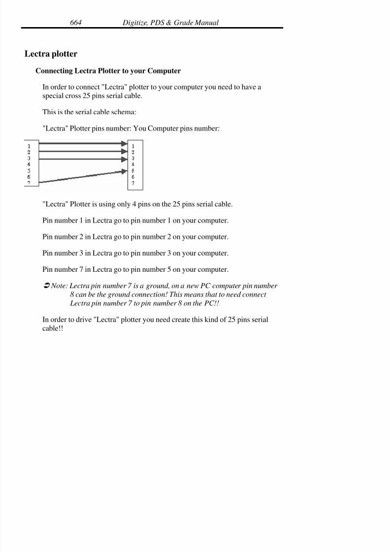
7/28/2019 OptiTex PDS User Manual
http://slidepdf.com/reader/full/optitex-pds-user-manual 685/727
Digitize, PDS & Grade Manual664
Lectra plotter
Connecting Lectra Plotter to your Computer
In order to connect "Lectra" plotter to your computer you need to have a
special cross 25 pins serial cable.
This is the serial cable schema:
"Lectra" Plotter pins number: You Computer pins number:
"Lectra" Plotter is using only 4 pins on the 25 pins serial cable.
Pin number 1 in Lectra go to pin number 1 on your computer.
Pin number 2 in Lectra go to pin number 2 on your computer.
Pin number 3 in Lectra go to pin number 3 on your computer.
Pin number 7 in Lectra go to pin number 5 on your computer.
! Note: Lectra pin number 7 is a ground, on a new PC computer pin number
8 can be the ground connection! This means that to need connect
Lectra pin number 7 to pin number 8 on the PC!!
In order to drive "Lectra" plotter you need create this kind of 25 pins serial
cable!!

7/28/2019 OptiTex PDS User Manual
http://slidepdf.com/reader/full/optitex-pds-user-manual 686/727
Chapter 17: Output Devices Installation 665
Where to connect your serial cable in "Lectra" plotter:
"Lectra" plotter module E32 or E33 has 7 serial COM output connects. One of
those 7 output connectors goes in to "Lectra" terminal. The terminalconnection is a flat serial cable with only 4 pins, you need to disconnect this
terminal cable and connect the terminal connection directly to you computer.
Don't put your cable in the terminal connections on the plotter, connect theterminal to your computer directly with your special crossed serial cable. Now
you can plot to your "Lectra" plotter.
In order to initialize the plotter you don't need "Lectra" terminal (you can use
"Lectra" terminal if you want to calibrate your plotter). OptiTexcommunication driver will initialize the plotter and set the pen position to
point 0.0!
Warnings:
• The default frame size is Y- 180 and X- 35. The frame size can
change (in case you are driving Lectra E-32 machine) from OptiTexplot dialog box.
• The emergency stop button on the plotter is not supported. Onceyou stopped the plotting. With the stop button, you have to re-send
the whole file again.
• The Lectra Terminal is disabled once you use OptiTex.
• OptiTex Lectra driver will initialize automatically before starting toplot.
How to Create Lectra Plot file in OptiTex version 8:
• After you finish nesting your pieces and you're ready to plot, go to
Plot dialog box.

7/28/2019 OptiTex PDS User Manual
http://slidepdf.com/reader/full/optitex-pds-user-manual 687/727
Digitize, PDS & Grade Manual666
• Check and enable "Use Output manager" option, select "OCC"("output manager service") section and press the Setup button.
• "Plotter Setup" dialog will be appearing.Note: if you are working with Win98 or Win95 you will need to
install OptiTex and reboot the computer in order to replacemsvcrt.dll and msvcp60.dll in your Windows system folder.
Without replacing these *.DLL the "Plotter Setup" dialog will work!
• Press the "Add" button to create a new plotter name and plotterqueue.
• To select a computer: select network or local computer (in order to
select a network computer you need to have a network computer
that already has a shared plotter queue) and then press "Next".
! Note: The enclosed explanation describes a local computer selection track.
• In the next dialog "Communication Setting" select "Lectra protocol"and the relevant COM port, DO NOT change any otherscommunication parameters and press the "next" button.
• The next dialog is a "Local Plotter Setting". In the plotter nameDialog box, write your plotter name. You can use any name but we
suggest using "Lectra".
(Don’t change the queue path for sharing, if your operating systemis not NT, you will need to define the share queue folder manually,
if you want other computers on the network to be able to plot to
your plotter.)Press "finish" button.
• Now you're back to the main "Plotter Setup" dialog window. Selectyour new plotter (Lectra) and press on "default button.
7/28/2019 OptiTex PDS User Manual
http://slidepdf.com/reader/full/optitex-pds-user-manual 688/727
Chapter 17: Output Devices Installation 667
• Close "Plotter Setup" dialog with "Close" button.
• If the plotter queue that you've just created is new, the"Plotter/Cutter Setup" dialog will open automatically. Select from
the driver format "Lectra Flat Bed Plotter" driver. Don't change the
plotter page size! It's recommended to use OptiTex font and not thePlotter font (don't use "use build - in font" option).
• Confirm your setting with Ok button. Now you're in "Plot" dialogbox and here you will see "Alert on start" option. If this option is
checked, the job that you are sending to the plotter is in "Hold"
attribute on the “OCC ".
• Confirm your settings and send the job to the plotter by pressing the
Ok button.Now the “OCC “will open. How to use “OCC "(Output Control
Center):The " OCC " is the OptiTex new output system and in order to drive
"Lectra" plotter you need to work with the "OCC". The new “OCC" supports "Lectra" communication driver.
• When the "OCC " is loaded (after you press the "plot" dialog box
"ok" button), you will see your plotter name in the "OCC" left side
under "All queues" header and your current job (the plotting data)will be in the "OCC" right side under "Jobs".
• If you job status is hold (remember "Alert on start" option in "Plot"dialog is checked) then in order to send the job to the plotter, press
on the "green flag" icon on the tool bar and your job will be send tothe plotter.
• In order to "re-send" a job you can go to "Done" under the queuename on the “OCC " left side, select the job and press the "restart"

7/28/2019 OptiTex PDS User Manual
http://slidepdf.com/reader/full/optitex-pds-user-manual 689/727
Digitize, PDS & Grade Manual668
button on " OCC " tool bar. You can also delete a job, stop a job and
sort jobs.
7/28/2019 OptiTex PDS User Manual
http://slidepdf.com/reader/full/optitex-pds-user-manual 690/727
Chapter 17: Output Devices Installation 669
Configuring the Cutting Edge Cutter
Connect the cutter
The cutter must be assembled and installed.
Install the Cutting Edge Software
Cutting Edge uses the Base module software to drive the cutter.
Configuring the SGS Grade, SGS PDS, or SGS Mark software
• From the FILE menu, choose PLOT.
! Note: To access the Plot command, there must be a piece in the working
area.
• In the PLOT dialog box, select following boxes:
Use – checked
Alert on Start, Alert on End, Remove on End, Copies - optional.
Options -Set to Plot Continuous.
Scale Factor - Set to X=1 Y=1.
Plotter Setting - Shows the Plotter language, Length and Width of page size.
! Note: Select the Setup button to configure plotter language and frame size.The Plot Setting dialog box will display.
Name - Shows the name of the plotter - Pltr1, Pltr2, etc.
Format - Cutting Edge

7/28/2019 OptiTex PDS User Manual
http://slidepdf.com/reader/full/optitex-pds-user-manual 691/727
Digitize, PDS & Grade Manual670
(0,0) In Page Center – unchecked
Manual Page Replace – checked
Use CR/LF in code – checked
Use M70 – unchecked
Use bitefeed offset – unchecked
Gap After Plotting - amount of space left between plots.
Minimal Cut/Plot Line - 0
Plotter Font File - eng.fnt file and it’s directory. If no font file is shown,
select Browse to locate the file.
Default Font Size - size of the text to the plot.
Number of Pen – 0
Min. Plot Spline Segment = .008
Plotter Page Size = X- longer than maximum marker
Y- useable width of paper minus margins
! Note: “Page Size” is the terminology generally used for plotters. However,
in the case of cutters, page size refers to the dimensions of the area
that the cutter cuts. If the Page Size setting is smaller than the marker size when creating an NC file, the file will be blank.
• Click OK to exit the PLOTTER SETUP dialog box.
• Click OK to exit the PLOT dialog box.

7/28/2019 OptiTex PDS User Manual
http://slidepdf.com/reader/full/optitex-pds-user-manual 692/727
Chapter 17: Output Devices Installation 671
Tips
Buttons with drill attributes work best when exporting to a Cutting Edge
cutter.
Using an AUX Drill attribute on buttons will execute a CUT command at the
cutter.
Using a Drill attribute on buttons will execute a DRILL command at the cutter.
Using a Cut attribute on buttons will execute a DRILL command at the cutter.
Using a Draw attribute on buttons will execute an INK command at the cutter.
I notches with cut attributes work best when exporting to a Cutting Edge
cutter.
T notches will draw as I notches at the cutter.
U, V, L, and box notches will cut the same shape at the cutter.
Operational Stops insert an M01 command at the cutter that causes the cutter
to pause before or after execution.
Darts will display as INK commands. The way that darts are displayed in the
SGS software determines how darts are displayed at the cutting edge machine.
When requesting the .NC file from the Mark software, Axis lines (pleats)
display as solid INK lines. When requesting the .NC file from the PDS
software, Axis lines (pleats) display as INK notches at the beginning and endof the line.
Internal lines display as INK or CUT lines depending on how the line
attributes are set in the SGS software.

7/28/2019 OptiTex PDS User Manual
http://slidepdf.com/reader/full/optitex-pds-user-manual 693/727
Digitize, PDS & Grade Manual672
Piece Descriptions and internal text display as ANNOTATION at the Cutting
Edge machine.
If the Base line is displayed in the SGS software, the baseline will display as
an INK command at the cutting edge machine.

7/28/2019 OptiTex PDS User Manual
http://slidepdf.com/reader/full/optitex-pds-user-manual 694/727
Chapter 17: Output Devices Installation 673
Eastman Cutter
There are several steps to follow when using the Eastman Cutter with the SGS
software:
• Installing the Eastman EasyCut program;
• Creating a .GBR file from Scanvec software;
• Importing the SGS .GBR file into Eastman software and cutting thefile.
This document provides information for step 2 above. For steps 1 and 3, pleaserefer to Eastman documentation.
Configuring SGS software
This document gives basic settings and configuration instructions used for
Eastman cutters.
Plot
• From the FILE menu, choose PLOT. The Plot dialog box willdisplay.
! Note: To access the Plot command, there must be a piece or a marker in the
working area.
File Name - Type in the name and path of the file. For example, if the file is tobe sent to a floppy diskette, type: A:\filename
If the file is to be sent to a directory on the C drive, type:
C:\directoryname\filename

7/28/2019 OptiTex PDS User Manual
http://slidepdf.com/reader/full/optitex-pds-user-manual 695/727
Digitize, PDS & Grade Manual674
Output Manager - Use Output Manager, Alert on Start, Alert on End,
Remove on End -Disable all of these options.
Page Format
Single and Multiple- Disable (uncheck).
Fixed Scale - Enable (checked).
Options
Plot Continuous - Enable (checked).
Scale Factor
X=1 Y=1
Check Intersections, Order by Tools, and One Page -Disable all of theseoptions.
Bulge - Set at .008
Plotter Setting - Shows the Plotter language and the Frame or Page size.
• Select the Setup button to configure plotter language and frame size.The Plot Setting dialog box will display.
Plot Setting
Name - Shows the name of the plotter - Pltr1, Pltr2, etc. The number of theplotter depends on how many plotters were identified during SGS softwareinstallation.
Format - Plotter Language should be set to Eastman Cutter.
7/28/2019 OptiTex PDS User Manual
http://slidepdf.com/reader/full/optitex-pds-user-manual 696/727
Chapter 17: Output Devices Installation 675
Device Options
(0,0) In Page Center - Disable (unchecked).
Number of Pens -Set at 0.
Manual Page Replace - Disable (unchecked).
Use CR/LF in code -Enable (checked)
Use M70 - Disable (unchecked).
Use bite feed offset - Disable (unchecked).
Font Options
Use Plotter’s Built-in Font -Enable (checked)
Plotter Font File - Should show the Plot-eng.fnt file and its directory. If nofont file is shown, select Browse to locate the file.
Default Font Size - This setting determines the size of the text on the plot.
! Note: This setting overrides the plot font settings specified elsewhere in the
program.
Gap After Plotting - Set at 0.
Minimal Cut/Plot Line - Set at 0.
Min. Plot Spline Segment- This setting determines the smallest spline or arc
to be cut as a spline or arc. This setting is not important for setup but may beadjusted later to improve the speed or quality of plots.

7/28/2019 OptiTex PDS User Manual
http://slidepdf.com/reader/full/optitex-pds-user-manual 697/727
Digitize, PDS & Grade Manual676
Plotter Page Size
X =128 The X value represents the frame size or table length.
Y = 43.5 The Y value represents the width of the material.
! Note: Be sure to set this setting correctly. If is set incorrectly, the cutter willnot cut or will cut incorrectly.
• Click OK to exit the Plotter Setup dialog box.
• Click OK in the Plot dialog box.
A .GBR file has now been generated and should be located under the path and
file name that was entered at the beginning of this section under “File Name.”
Tips
1/4 inch T notches with a cut and no stop attribute cut best at the Eastman
cutter.
Buttons with a Drill M43 attribute cut best at the cutter.

7/28/2019 OptiTex PDS User Manual
http://slidepdf.com/reader/full/optitex-pds-user-manual 698/727
Chapter 17: Output Devices Installation 677
Configuring the Gerber Cutter S3250
Connect the cutter
The cutter must be assembled and installed.
Install the Gerber Software
Gerber uses the Power Processor software to drive the cutter.
Configuring the SGS software
• From the FILE menu, choose PLOT.
! Note: To access the Plot command, there must be a piece in the working
area.
• In the PLOT dialog box, select following boxes:
(Use = checked)
Alert on Start, Alert on End, Remove on End, Copies = optional
Page Format = fixed scale
Options = Set to Plot Continuous.
Scale Factor = Set to X=1 Y=1
Whole pieces in frame only
Check intersections before plotting
Optimize Plot/Cut Order

7/28/2019 OptiTex PDS User Manual
http://slidepdf.com/reader/full/optitex-pds-user-manual 699/727
Digitize, PDS & Grade Manual678
Plotter Setting = Shows the Plotter language, Length and Width of page size.
! Note: Select the Setup button to configure plotter language and frame size.
The Plot Setting dialog box will display.
Name = Shows the name of the plotter - Pltr1, Pltr2, etc.
Format = Gerber Cutter
(0,0) in Page Center = unchecked
Manual Page Replace = unchecked
Use CR/LF in code = unchecked
*Use initialization in file header (M70…) = checked
Use Bitefeed Offset = unchecked (if using Version 7.x. If using a lower
version: *Use bitefeed offset = checked, -.50)
Gap After Plotting = amount of space left between plots.
Minimal Cut/Plot Line = 0
Use Plotter’s Built-in Font = unchecked
Plotter Font File = eng.fnt file and it’s directory. If no font file is shown,
select Browse to locate the file.
Default Font Size = size of the text to the plot.
Number of Pen = 0
Min. Plot Spline Segment = .008
Plotter Page Size = X- 999
7/28/2019 OptiTex PDS User Manual
http://slidepdf.com/reader/full/optitex-pds-user-manual 700/727
Chapter 17: Output Devices Installation 679
Y- 70 (useable width of paper minus margin)
! Note: “Page Size” is the terminology generally used for plotters. However,
in the case of cutters, page size refers to the dimensions of the area
that the cutter cuts. If the Page Size setting is smaller than the marker
size when creating an NC file, the file will be blank.
• Click OK to exit the PLOTTER SETUP dialog box.
• Click OK to exit the PLOT dialog box.
Tips
I or V notches with cut attributes work best when exporting to a Gerber cutter
Configuring the Gerber Cutter S-91
There are 3 main steps to configuring the Gerber Cutter for use with the SGSsoftware: 1) Connecting the cutter, 2) Installing the Gerber software, 3)
Configuring the SGS programs.
Connect the cutter
The cutter must be assembled and installed.
Install the Gerber Software
Gerber uses the Power Processor software to drive the cutter.
Configuring the SGS Software
• From the FILE menu, choose PLOT.

7/28/2019 OptiTex PDS User Manual
http://slidepdf.com/reader/full/optitex-pds-user-manual 701/727
Digitize, PDS & Grade Manual680
! Note: To access the Plot command, there must be a piece in the working
area.
• In the PLOT dialog box, select following boxes:
(Use = checked)
Alert on Start, Alert on End, Remove on End, Copies = optional
Page Format = fixed scale
Options = Set to Plot Continuous.
Scale Factor = Set to X=1 Y=1
Whole pieces in frame only
Check intersections before plotting
Optimize Plot/Cut Order
Plotter Setting = Shows the Plotter language, Length and Width of page size.
! Note: Select the Setup button to configure plotter language and frame size.
The Plot Setting dialog box will display.
Name = Shows the name of the plotter - Pltr1, Pltr2, etc.
Format = Gerber Cutter
(0,0) in Page Center = unchecked
Manual Page Replace = unchecked
Use CR/LF in code = unchecked

7/28/2019 OptiTex PDS User Manual
http://slidepdf.com/reader/full/optitex-pds-user-manual 702/727
Chapter 17: Output Devices Installation 681
*Use initialization in file header (M70…) = checked
*Use bitefeed offset = checked, -. 50
Gap After Plotting = amount of space left between plots.
Minimal Cut/Plot Line = 0
Use Plotter’s Built-in Font = unchecked
Plotter Font File = eng.fnt file and it’s directory. If no font file is shown,select Browse to locate the file.
Default Font Size = size of the text to the plot.
Number of Pen = 0
Min. Plot Spline Segment = .008
Plotter Page Size = X- 110
Y- 70 (useable width of paper minus margin)
! Note: “Page Size” is the terminology generally used for plotters. However,
in the case of cutters, page size refers to the dimensions of the area
that the cutter cuts. If the Page Size setting is smaller than the marker
size when creating an NC file, the file will be blank.
• Click OK to exit the PLOTTER SETUP dialog box.
• Click OK to exit the PLOT dialog box.
Tips
I or V notches with cut attributes work best when exporting to a Gerber cutter

7/28/2019 OptiTex PDS User Manual
http://slidepdf.com/reader/full/optitex-pds-user-manual 703/727
Digitize, PDS & Grade Manual682
Configuring the Gerber Cutter S-93
There are 3 main steps to configuring the Gerber Cutter for use with the SGS
software: 1) Connecting the cutter, 2) Installing the Gerber software, 3)Configuring the SGS programs.
Connect the cutter
The cutter must be assembled and installed.
Install the Gerber Software
Gerber uses the Power Processor software to drive the cutter.
Configuring the SGS Grade, SGS PDS, or SGS Mark software
• From the FILE menu, choose PLOT.
! Note: To access the Plot command, there must be a piece in the working
area.
• In the PLOT dialog box, select following boxes:
(Use = checked)
Alert on Start, Alert on End, Remove on End, Copies = optional
Page Format = fixed scale
Options = Set to Plot Continuous.
Scale Factor = Set to X=1 Y=1
Whole pieces in frame only

7/28/2019 OptiTex PDS User Manual
http://slidepdf.com/reader/full/optitex-pds-user-manual 704/727
Chapter 17: Output Devices Installation 683
Check intersections before plotting
Optimize Plot/Cut Order
Plotter Setting = Shows the Plotter language, Length and Width of page size.
! Note: Select the Setup button to configure plotter language and frame size.The Plot Setting dialog box will display.
Name = Shows the name of the plotter - Pltr1, Pltr2, etc.
Format = Gerber Cutter
(0,0) in Page Center = unchecked
Manual Page Replace = unchecked
Use CR/LF in code = unchecked
*Use initialization in file header (M70…) = checked
*Use bitefeed offset = checked, -. 50
Gap After Plotting = amount of space left between plots.
Minimal Cut/Plot Line = 0
Use Plotter’s Built-in Font = unchecked
Plotter Font File = eng.fnt file and it’s directory. If no font file is shown,select Browse to locate the file.
Default Font Size = size of the text to the plot.
Number of Pen = 0

7/28/2019 OptiTex PDS User Manual
http://slidepdf.com/reader/full/optitex-pds-user-manual 705/727
Digitize, PDS & Grade Manual684
Min. Plot Spline Segment = .008
Plotter Page Size = X- 110
Y- 70 (useable width of paper minus margin)
! Note: “Page Size” is the terminology generally used for plotters. However,in the case of cutters, page size refers to the dimensions of the area
that the cutter cuts. If the Page Size setting is smaller than the marker
size when creating a NC file, the file will be blank.
• Click OK to exit the PLOTTER SETUP dialog box.
• Click OK to exit the PLOT dialog box.
Tips
I or V notches with cut attributes work best when exporting to a Gerber cutter

7/28/2019 OptiTex PDS User Manual
http://slidepdf.com/reader/full/optitex-pds-user-manual 706/727
Glossary Terms 685
Glossary Terms
AAMA
Refers to a “neutral” file format created by the American Apparel Manufacturing
Association.
About
Selecting the About icon on the Standard toolbar in OptiTex PDS or the
Marker toolbar in OptiTex Mark activates a dialog box displaying theversion of software currently in use.
Align
A command found in the Edit Menu of OptiTex PDS that repositionspoints horizontally, vertically, or at an assigned angle based on the
selection of two or more points.
Array
A command found in the Marker Menu of OptiTex Mark, which allows
selected piece(s) to be arranged into rows and columns automatically onthe marker as specified in the Array dialog box.
Baseline
Baseline, also referred to as a grainline, controls the pattern piece’salignment in the working area and on the marker.
Base Size
The pattern size from which the program bases pattern changes and grade.

7/28/2019 OptiTex PDS User Manual
http://slidepdf.com/reader/full/optitex-pds-user-manual 707/727
Glossary Terms686
Buffer
An assigned area of space placed on a single pattern or patterns in
OptiTex Mark. A buffer is often used to create extra space between
pattern pieces when cutting difficult fabrics.
Bundle
A pattern making term that refers to all patterns pieces necessary to make
one complete item or Set.
Click
The action of pressing down on the left mouse button to select an objector command on the screen.
Clipboard
A location on the computer where items are stored when they are cut orcopied from a file or document. Items remain on the clipboard until
another item is cut or copied.
Contour
The perimeter of the pattern piece.
Cursor
The screen symbol (e.g. the arrow) that indicates the position of the
mouse on the computer screen.
Dart
Shaped tuck pointed at one or more ends to remove excess material and

7/28/2019 OptiTex PDS User Manual
http://slidepdf.com/reader/full/optitex-pds-user-manual 708/727
Glossary Terms 687
Make a garment fit .
Delta Value
This refers to the X and Y-axis used for directional movement on the
working area. The X-axis represents the horizontal movement and the Y-
axis represents the vertical movement.
Dialog Box
The pop-up window that appears while using editing tools allowing the
user to insert parameters for a specific command.
7/28/2019 OptiTex PDS User Manual
http://slidepdf.com/reader/full/optitex-pds-user-manual 709/727
Glossary Terms688
Digitizing
The process of converting a two-dimensional object into data points asdigital numbers, which are imputed into the computer to represent the
pattern pieces.
Directory
User-defined sections on the computer were file could be stored. ( e. g.
C:\Optitex7\Examples).
Display File
A marker file, usually containing one or more design files, which has been
nested. (e.g. filename.dsp).
DXF
The graphical Data Exchange Format used by CAD systems to transfer
geometric information.
Drive
The address of the storage media to be accessed: usually A and B for
removable diskettes and C, D for permanent hard disk or CD-ROM drive.
DSN File
DSN is the SGS extension for a OptiTex PDS file.
DSP File
DSP is the SGS extension for a Mark file.
7/28/2019 OptiTex PDS User Manual
http://slidepdf.com/reader/full/optitex-pds-user-manual 710/727
Glossary Terms 689
EXE
Extension denoting a program file. This is a compiled computer program
executable from DOS or from Windows by typing the file name on the
command line and pressing the Enter key (DOS) or by double click on itsname (Windows).
Exit
Normal termination of software program.
Field
The white spaces in a dialog box where information can be entered.
File Extension
The three letters suffix at the end of a filename, which defines the format.For example: DSP, DSN, EXE, etc.
Flipping
The act of transposing the pattern piece horizontally or vertically while it
is located in the working area.
Global Rule
A grading rule based on the total number of grading points of any pattern.
Also called, “All Points Rule”.
Graded Pattern
A pattern that points have been assigned grading rules to control the way apiece changes from size to another.

7/28/2019 OptiTex PDS User Manual
http://slidepdf.com/reader/full/optitex-pds-user-manual 711/727
Glossary Terms690
Grading
The process of assigning measurement increments to a pattern to
determine how each size of the pattern should increase or decrease in
relation to the previous size.
Grading Point
A point on the pattern contour, line and curve, which you can attach a
grading value.
7/28/2019 OptiTex PDS User Manual
http://slidepdf.com/reader/full/optitex-pds-user-manual 712/727
Glossary Terms 691
Grading Rule
The assigned measurement increments to define the grading at a point onthe pattern piece for all sizes. There are three types of grading rules: fixed,
point and global.
Grading Table
A display window activated from the Grading Menu that displays the
assigned measurement increments for previously established gradingrules.
Grainline
Grainline, also referred to as a baseline, controls the pattern piece’salignment in the working area and on the marker.
Graphic Standard
The ASCII geometry in CAD/CAM file formats, which renders themcompatible with SGS programs.
Grayed Out
Refers to features or commands that are unavailable at the current time.Features and commands are typically grayed out when a selected item on
the piece does not correspond to the feature or command.
Group
A term used in OptiTex Mark to describe two or more selected patterns
that have been added to the pattern list and nested on the marker as asingle unit. The Group is established by highlighting the pieces and
selecting Keep in the Grouping Menu of OptiTex Mark.

7/28/2019 OptiTex PDS User Manual
http://slidepdf.com/reader/full/optitex-pds-user-manual 713/727
Glossary Terms692
Handle Point
Any notch or button with the number 1.
7/28/2019 OptiTex PDS User Manual
http://slidepdf.com/reader/full/optitex-pds-user-manual 714/727
Glossary Terms 693
Hard Drive
A device made of aluminum disks coated with iron oxide permanentlymounted in the computer to store data and programs. Hard disks have
more storage capacity than floppy disks.
Hex
Hexadecimal. A number written in base 16, which contains 16 possible
digits: 0, 1, 2, 3, 4, 5, 6, 7, 8, 9, A (10), B (11), C (12), D (13), E (14) andF (15).
Icon
Icons are located on the toolbars and provide the pattern maker with fastaccess to the design tools.
Internals
Lines or points which are not located on the contour, and which can beused for style or cutting purposes.
Intersections
A term used in OptiTex Mark to describe the points where nested patternsoverlap on the marker area.
Invert
To relocate the first point on a selected line segment from one end the
opposite end. This command can be found in the Edit Menu of OptiTex
PDS by selecting Segment and Show.

7/28/2019 OptiTex PDS User Manual
http://slidepdf.com/reader/full/optitex-pds-user-manual 715/727
Glossary Terms694
Key
A small piece of hardware approximately 1.5” by 2” with 25 small prongs
on one end and 25 small inlets or holes on the other end. This key is
plugged into a parallel port on the back of the computer. If the computerhas a printer attached, the key is plugged into the back of the printer plug
as if to piggyback on the printer plugs. This item is what permits SGS
software to run on your computer. When this key is not plugged into theback of the computer, a “HASP plug not found” error displays on the
screen in the HASP Error Message dialog box. Authorizer keys are
designed to prevent illegal copying and illegal use of software. Anauthorizer key is also referred to as, Plug, Security Lock, Lock or Dangle.
Landscape Mode
The Landscape mode is the opposite of Portrait Mode in printer setup. Itallows output to be printed in the width direction of the paper.
Lock
See “Key ”.
Marker
The physical layout of all the pieces in a style cut from the same material
at the same time.
Marker File
A file created in OptiTex Mark that contains a nested marker.
Marker Size
The dimensions of the marker that have been specified in the Marker
Definitions dialog box of the Marker Menu in OptiTex Mark.

7/28/2019 OptiTex PDS User Manual
http://slidepdf.com/reader/full/optitex-pds-user-manual 716/727
Glossary Terms 695
Mirror
This command creates a symmetrical pattern piece by joining two pieces,
the original and a duplicate inverted piece, at a two-point line segment
that is selected before using the Mirror command from the Piece Menu inOptiTex PDS.
Nest
A term used to indicate the close placement of pieces on a marker layout.

7/28/2019 OptiTex PDS User Manual
http://slidepdf.com/reader/full/optitex-pds-user-manual 717/727
Glossary Terms696
Network
A collection of devices such as computers and printers, that are connectedtogether. A network is a tool for communication that allows users to store
and retrieve information, share printers and exchange information.
Nested Pattern
A pattern that is drawn to show more than one size of the piece stacked on
top of each other also called a stacked piece or graded nest.
Nesting
The placement of pieces on a marker to achieve the most compact and
efficient layout.
Notch
A symbol placed on a pattern to indicate where the piece should be
aligned with another piece when the two are sewn together.
On-line Help
Help accessed by using either the F1 key for general index or Shift F1
keys for specific help when an option or command is selected.
Order
An order is generated in OptiTex Mark to set up the marker. The orderwill include information such as the design files to be nested on the
marker, the fabric width, and the number of each piece in the design file.
Output
Refers to data that is either printed or plotted.

7/28/2019 OptiTex PDS User Manual
http://slidepdf.com/reader/full/optitex-pds-user-manual 718/727
Glossary Terms 697
Path
The alphanumeric code that guides the computer to a specific drive/
directory/file based on the default selection defined in Autoexec.bat file.
Piece Display Bar
Refers to a pictorial list of pieces within a design file. The Piece Display
Bar shows a small picture of each piece in a design file.
Piece List
A window that is activated from the Display Menu in OptiTex PDS and
displays the pattern pieces for the current design file.
Plot File
A file created for printing purposes. The resulting plot file can be sent to
the output device from any PC (not necessarily equipped with SGS
software) with the DOS Copy command.
Point
The part of a piece’s boundary lines used to control the shape of the piece.
A point may be a grading point or a non-grading point.
Point Rule
A rule, which is attached to a specific point and is related to the number of
sizes which are currently open, and only to those sizes.
7/28/2019 OptiTex PDS User Manual
http://slidepdf.com/reader/full/optitex-pds-user-manual 719/727
Glossary Terms698
Polyline
Contour elements with shared attributes. (See also Single Elements).
Pop-up Menu
A list of options that appear on the screen after the right mouse button isclicked.
Pop-up Window
A window displayed on the working area as a result of user selected option.
Portrait Mode
The Portrait Mode is the opposite of Landscape Mode in printer setup. It
allows output to be printed in a lengthwise direction on the paper.
Remainders
The number of unplaced pieces in a marker file.
Right Mouse Click
The action of pressing down on the right mouse button to select an object
or command on the screen.
Round
The act of modifying an angle into a curve.
Rule Library
A collection of existing grading rules which can be attached to a pattern.
Scroll
When the number of items in a window/dialog box exceeds the amount of

7/28/2019 OptiTex PDS User Manual
http://slidepdf.com/reader/full/optitex-pds-user-manual 720/727
Glossary Terms 699
space for display, an elevator bar appears at the right. By positioning the
mouse on this bar, the user can view all items at one window height.
Security Lock
See “Key ”.
Selected Piece
The piece displayed in the working area with a dashed line around the
piece perimeter.
Selection Tool
The screen symbol (e.g. the arrow) that indicates the position of the
mouse on the computer screen.
Set
A pattern making term that refers to all pattern pieces necessary to make
one complete item or Bundle.
Shrink Factor
The amount a pattern is increased or decreased to allow for the
dimensional of the fabric.
Size List
The box displaying all sizes being produced for a specific design file.
Snap
When using a grid on the working area in OptiTex PDS, this option
causes the cursor to jump to the nearest point, whether it be a contour

7/28/2019 OptiTex PDS User Manual
http://slidepdf.com/reader/full/optitex-pds-user-manual 721/727
Glossary Terms700
point, grid point or piece’s end point (grid points have priority).
Solution File
A completed order of nested patterns.
Stack Point
One point on a nested pattern where the grading is set at 0,0 for all sizes inthe nest.
Swap Pieces
This icon in OptiTex PDS interchanges the original pattern piece in thepiece display bar with the piece being edited in the working area.
Toggle
Refers to the action of turning a command on/off by checking or
unchecking an item. For example, many options in the Display Menu
toggle between displaying on screen or not displaying on screen.
Tolerance Value
The maximum distance between two points on a contour to treat the
points as a single point.
Toolbar
A collection of icons positioned in a row on the screen. Toolbars provideeasy access to commands and features when using the mouse.
Tools
Design functions in the software that enables the patternmaker to

7/28/2019 OptiTex PDS User Manual
http://slidepdf.com/reader/full/optitex-pds-user-manual 722/727
Glossary Terms 701
manipulate patterns.
Waste Limits
This area is created on the markers edge prevents the cutting of pieces
were the fabric in flawed. The area can be defined in the Marker Menu
under Marker Definitions.
Working Area
The area of the screen where pattern pieces are placed for editing.
WYSIWYG
This stands for, “What You See Is What You Get.” This concept is used
in the SGS software to indicate that what appears on the computer screen
is what will be printed or plotted onto paper.
X, Y Coordinates
A method of defining the horizontal (x) and vertical (y) location of grade
points, notch attributes, and internals. X, Y coordinates also indicate howmuch grade points increase in the horizontal and vertical direction.

7/28/2019 OptiTex PDS User Manual
http://slidepdf.com/reader/full/optitex-pds-user-manual 723/727
Index
A
About OptiTex PDS, 33
Angle, 41
Attributes, 41
Advanced Toolbar, 102
Axes command and tool, 71
Attaching the digitizer menu., 151Attaching the Digitizer Panel, 151
Actual Size, 247
Alert on Start, 227
Annotation, 200, 215
Add Relative, 268
Align Points, 274
Attributes, 265
Angle, 304
Apply, 294
All Points, 360
Append, 344
Apply Rule, 362
Apply Rule Dialog Box, 363Add To Library, 415
Auto reseam, 451, 454
About OptiTex Grade, 461
B
Box, 60
Button, 66, 67
Browse, 195
16 button cursor, 195
Base Size Mark, 201, 215
Best Quality, 201, 215
Boundary Lines, 212
Bulge (cored Error) Inches, 242Button Attributes Dialog Box, 271
Base Parallel to Segment, 315
Baseline Only, 304
Best Quality, 290
Buffer, 290 Button Attributes Dialog Box, 71
Base Parallel to Segment, 315
Baseline Only, 304
Best Quality, 290
Buffer, 290
Base Only (F4), 429
Base size only box, 385
Bitmap Directory, 398Base Size, 347, 348
C
Context Help, 34
Copy Grading (Ctrl + G + C), 22, 23,339
CCW Folded, 61
Circle, 64, 65
Clip Fabric Pattern, 102
Counter Clockwise, 63
Cut, 112, 113
Cut Along Internal, 114
Communication Port, 195Customizing the Digitizer Panel:, 164
Cad Files to Import, 203
Change Log, 229
Copies, 228, 289, 290
Current Plotter, 244
Curve Points, 213,266
Clear Pieces, 259
Copy, 278, 434
Copy Piece, 257
Cut Piece, 255, 256
Chapter 6 Piece Menu, 287
Clip Fabric Pattern, 331
Code, 289
Copies, 289, 290
Chapter 6 Piece Menu, 287
Clip Fabric Pattern, 331
Code, 289
Chapter 11
Clear, 434
Compare Length, 430, 431, 433

7/28/2019 OptiTex PDS User Manual
http://slidepdf.com/reader/full/optitex-pds-user-manual 724/727
Index
Coordinates, 421, 422
Close Rule Library, 356
Create New Rule Library, 355
Copy/Paste, 385
Countries, 397
Create By Measure, 405
Create Parallel, 381
Create Parallel Cutting, 410
Curve, 386
Curve length, 404
Custom Fit, 392
Custom fit tools, 398
Choose, 417
Colours, 445, 446
Contour to draft, 440
Chapter 10Help, 459
Check Plug Protection, 460
D
Dart, 50Delete, 34, 35
Depth, 40, 53
Direction, 53
Disengaging a Tool, 21
Dart rotation according pivot point, 56
Depth, 61
Distance, 54
Draft, 113, 116
Drill Draw Cut None, 54
Digitizer Communication Setup, 196
Digitizer Panel, 163
Digitizer Setup, 163
Digitizer Type, 194
Digitizing a pattern using a 16 button cursor:
161
Digitizing a pattern using a 4 button cursor:
162
Drive and Directory, 127
Dictionary Dialog Box, 200, 214
Drill Holes, 213
Description, 289
Direction, 326
Distance Moving, 326
Distance Stationary, 326
Delete 346
Delete Rule, 361
Default Notch, 456, 457
Design Menu, 381
E
Engaging a Tool, 21
Equal X Grading (Ctrl + G + E), 24,25
Equal for All Sizes, 54
Edit Panel, 195
Exit (Alt+F4), 253
Export to CAD/CAM file Dialog Box, 198
Export to CAD/CAM Files, 197
Extend Internal Line, 276
Edit Dimension Dialog, 401
Edit Measure, 398Edit/Delete measures, 404
Expression, 400
Extend, 386
Equal X Grading (Ctrl + G + E), 341,342
Export Rule Library, 364
F
Flip X Grading (Ctrl + G + F), 24,341
From Next, 45
From Previous, 43
First, 61
Flip Along tool, 120
Flip Horizontal, 84,305Flip Vertical, 84,305
Folding out tool, 117
File Menu, 125
File Name and File List Box, 127,146
Find now, 138
Finder Dialog, 135

7/28/2019 OptiTex PDS User Manual
http://slidepdf.com/reader/full/optitex-pds-user-manual 725/727
Index
File Format, 204
File Name and Browse, 227
Fit to Page, 247
Fixed Scale, 240
Format, 198, 212, 231
Fabric and Stripes, 327
Folding Allowed, 294
Fabric and Stripes, 327
Folding Allowed, 294
F3, 478
F6, 479
Fonts, 447
First Diagonal, 386
First Horizontal, 386
First Vertical, 386
Fit to measures, 394
Fixed Rule, 361
Flip Y Grading (Ctrl + G + L), 341
G
Gap after Plotting, 234
Grain (Base) Lines, 213
Grading Points, 267
Global Change Internal’s Parameters, 299
Global Info, 295
Global Pattern Information Dialog Box, 295
Grading Manually by Edit Tool, 450
Grid and Stripes, 443
Grading Library, 429
Grading Table, 429
Group, 397
H
Height, 248
History, 131, 132, 133
Hide Fabric Pattern, 102, 331
Holes and Internal Contours, 301
How to Contact SGS, 464
Hide/Show measures, 403
Hole By measure, 408
Hole to Piece, 387
Horizontal Fit, 393
I
Ignore CR. / LF, 210
Ignore Frame, 211Ignore Internals, 205
Import CAD files Dialog Box, 203
Import from CAD/CAM Files, 201
Internal Cut, 213
Internal Lines (draw), 213
Info, 287, 289
Insert 346, 468
Index (F1), 459
I Show Point Numbers, 429
Import Rule library, 355
J
Join Pieces, 109Join Pieces Dialog Box, 111
K
Knife, 60
Keyboard Commands, 477
L
Look in subfolders, 136
Layers Table Dialog Box, 200, 212
Lock Piece (F3), 452
Last Diagonal, 387
Last Horizontal, 386Last Vertical, 386
Length, 385
M
Make New, 100
Max All, 96

7/28/2019 OptiTex PDS User Manual
http://slidepdf.com/reader/full/optitex-pds-user-manual 726/727
Index
Measure, 107
Move, 80, 81,261
Move Parallel, 76, 77
Move Point, 73
Move Proportional, 75
Match case, 137
Match whole word only, 137
Material filter, 137
Merge DSN File, 128
Make DSN files, 205
Manual Page Replace, 232
Marker Boundary, 241
Marker Header, 241
Material Code, 201, 215
Max Grade Angle, 210
Minimal Plot/Cut line, 234
Multiple, 240
Make Circle Dialog Box, 285
Make New, 260
Make Pieces, 283
Make Polygon Dialog Box, 284Make Rectangle Dialog Box, 284
Make New Base Line, 317
Material, 205, 290, 298
Max Tilt, 291
Mirror, 306
Make Circle Dialog Box, 285
Move Base Line, 473
Measure Bitmap, 398
Measurements Names, 405
Measures setup, 396
N
New (Ctrl + N), 31
Next Point, 30
Notch, 37
Number of Pleats, 61
Name, 231,289
Network Plotting, 227
No Size, 204
Notches, 213
Note, 229
Notch Both (F12), 327
Notch Moving (F12 + Shift), 327
Notch Stationary (F12 + Ctrl), 327
New Grading Rule Dialog Box, 358
New Rule, 356, 357
O
Overlap, 53
Open Dialog Box, 127
Open file, 138
Page in Center, 232
Open Style File, 140
Options, 128
Order by Tools, 242
Orientation, 201, 216
Output Manager INI File, 244Optimize Cutter Ordering, 311
Open Rule Library, 355
Orientation, 291, 292
Open Create Dialog, 451
Open Move Dialog, 450
Open move Piece dialog, 451
Open Library, 413
Optimize Cutter Ordering, 311
Orientation, 291, 292
Open (Ctrl+O), 126
P
Paste Grading (Ctrl + G + P), 23,340Paste Relative (Ctrl + G + R), 22,339
Paste X Grading (Ctrl + G + X), 23
Paste Y Grading (Ctrl + G + Y), 23
Pointer, 31
Previous Point, 22
Proportional, 42

7/28/2019 OptiTex PDS User Manual
http://slidepdf.com/reader/full/optitex-pds-user-manual 727/727
Index
Pattern Group, 405
Piece to Hole, 387
Pleat, 59
Pleat Characteristics Dialog Box, 60
Pleats First Distance, 62
Panel, 195
Piece Code filter, 137
Piece name filter, 136
Preparing patterns for digitizing, 152
Printing the Digitizer Panel, 165
Piece Code, 200, 215
Piece Name, 200, 215
Plot, 219, 220
Plot Continuous, 241
Plot Setting Dialog Box, 230
Plotter (Output Manager) Setup, 221
Plotter Page Size (inches), 234
Plotter Setting, 230
Plotter Setup Dialog, 244
Print, 246
Print Dialog Box, 247Print selected pieces only, 248
Page in Center, 232
Print to file, 248
Printer Setup, 248
Printer Setup Dialog Box, 249
Paste between Two Points, 282
Paste Segment Proportional, 281
Piece, 304,422,472
Point Cleanup, 312
Print Report, 294, 298
Paste between Two Points, 282
Piece List, 423
Q
Quality Lines, 214
Quantity, 201, 205, 215
R
Redo (Ctrl+Y), 98, 255
Remove Current, 99
Replace Old, 101,259
Rotate Piece, 83
Rotate Segment, 82
Reconnect, 40Report, 142
Resolution, 195
Remove Current, 260
Round Corner, 275
Remove on End, 228
Report to Log, 229
Restore Defaults, 201, 214, 216
Ratio, 325
Relate Piece to Stripes, 332
Reseam (F6), 319
Rotate, 301
Rotate Directions, 291
Rotate Left and Rotate Right, 304Rotate To Initial Base Line, 305
Replace Old, 259
Reseam (F6), 319
Rotate, 301
Rotate Directions, 291
Rotate Left and Rotate Right, 304
Rotate To Initial Base Line, 305
Right Mouse Button, 465
Rulers, 422
Refresh 385
Rename Rule Name, 361
Reshape Variation grading, 338
S
Save, 32,144
Seam, 47, 48, 49, 267, 318
Size, 40, 277, 298
Show Control Points, 103
Show Fabric Pattern, 102