Embed Size (px)
Citation preview

7 Capella CourtNepean, ON, CanadaK2E 7X1
+1 (613) 224-4700www.optiwave.com
© 2
009 O
ptiw
ave S
yste
ms, In
c.
OptiSystem applications:Matched filter analysis
2
Introduction (1)
� A matched filter is an ideal filter which acts upon a received signal so as to maximize its signal to noise ratio (SNR). Under conditions of additive white Gaussian noise, the SNR is maximized when the impulse response of the receiver filter is an exact copy of the transmitted waveform (but reversed and time delayed)
� For symmetrical pulses (such as square NRZ), the optimum matched filter is the integrate and dump (or integrator) receiver. This receiver model is demonstrated for the following transmission designs:
� Two level amplitude shift keying (ASK) with direction detection
� Electrical coherent receiver (using binary PSK antipodal modulation)
� Electrical coherent receiver (using binary FSK modulation)
� Although the I&D filter is an optimum filter for additive white Gaussian noise, it requires excellent timing precision for sampling (low jitter). The reason for this is that the optimum sampling point for the I&D is right at the end of the bit/symbol period (the end of the integration cycle before resetting the integrator)
� Another filtering method which uses the concept of matched filtering is the root raised cosine (RRC) filter. This configuration involves pre-filtering (pulse shaping) the transmitted signal with an RRC filter followed by a second RRC filter just before the decision (the combined result being a raised cosine transfer function). This filter set is very popular in communication systems as it provides good performance against inter symbol interference (ISI). An example design is demonstrated for ASK with direct detection.
References
- H. Taub & D.L. Schilling, Principles of Communication Systems, McGraw-Hill (1986), pp. 444-458
- “Linear Time Invariant (LTI) Systems and Matched Filter ”, 1998/2002 Charan Langton, http://complextoreal.com/wp-content/uploads/2013/01/mft.pdf; accessed 24 June 2017
Matched filter analysis
3
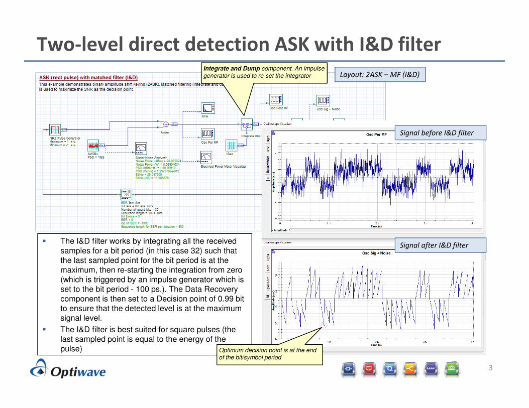
Two-level direct detection ASK with I&D filter
Layout: 2ASK – MF (I&D)
Signal before I&D filter
Signal after I&D filter� The I&D filter works by integrating all the received
samples for a bit period (in this case 32) such that the last sampled point for the bit period is at the maximum, then re-starting the integration from zero (which is triggered by an impulse generator which is set to the bit period - 100 ps.). The Data Recovery component is then set to a Decision point of 0.99 bit to ensure that the detected level is at the maximum signal level.
� The I&D filter is best suited for square pulses (the last sampled point is equal to the energy of the
pulse) Optimum decision point is at the end
of the bit/symbol period
Integrate and Dump component. An impulse
generator is used to re-set the integrator
4
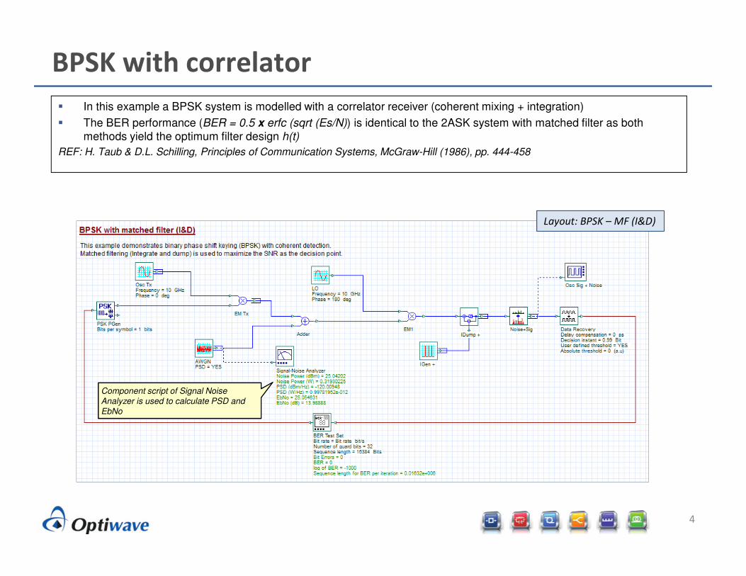
BPSK with correlator
� In this example a BPSK system is modelled with a correlator receiver (coherent mixing + integration)
� The BER performance (BER = 0.5 x erfc (sqrt (Es/N)) is identical to the 2ASK system with matched filter as both methods yield the optimum filter design h(t)
REF: H. Taub & D.L. Schilling, Principles of Communication Systems, McGraw-Hill (1986), pp. 444-458
Layout: BPSK – MF (I&D)
Component script of Signal Noise
Analyzer is used to calculate PSD and
EbNo

5
BFSK with correlator
� In this example a BFSK system is modelled with a correlator receiver (coherent mixing + integration)
� The BER performance (BER = 0.5 x erfc (sqrt (Es/2N)) is slightly worse compared to BPSK due to the splitting of powers
REF: H. Taub & D.L. Schilling, Principles of Communication Systems, McGraw-Hill (1986), pp. 444-458
Layout: BFSK – MF (I&D)
6
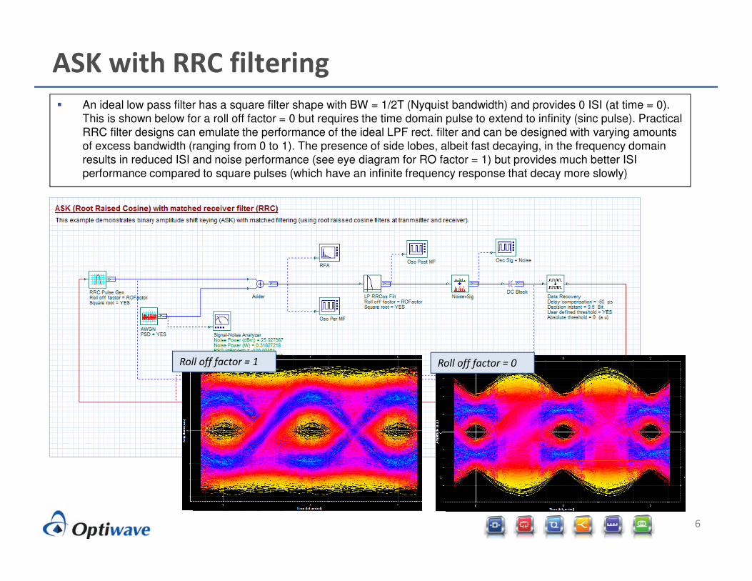
ASK with RRC filtering
� An ideal low pass filter has a square filter shape with BW = 1/2T (Nyquist bandwidth) and provides 0 ISI (at time = 0). This is shown below for a roll off factor = 0 but requires the time domain pulse to extend to infinity (sinc pulse). Practical RRC filter designs can emulate the performance of the ideal LPF rect. filter and can be designed with varying amounts
of excess bandwidth (ranging from 0 to 1). The presence of side lobes, albeit fast decaying, in the frequency domain results in reduced ISI and noise performance (see eye diagram for RO factor = 1) but provides much better ISI performance compared to square pulses (which have an infinite frequency response that decay more slowly)
Roll off factor = 1 Roll off factor = 0

7
BER waterfall curves (ASK with I&D)
� For ASK with matched filter, BER = 0.5 x erfc (sqrt (Es/N))
REF: H. Taub & D.L. Schilling, Principles of Communication Systems, McGraw-Hill (1986), pp. 444-458
8
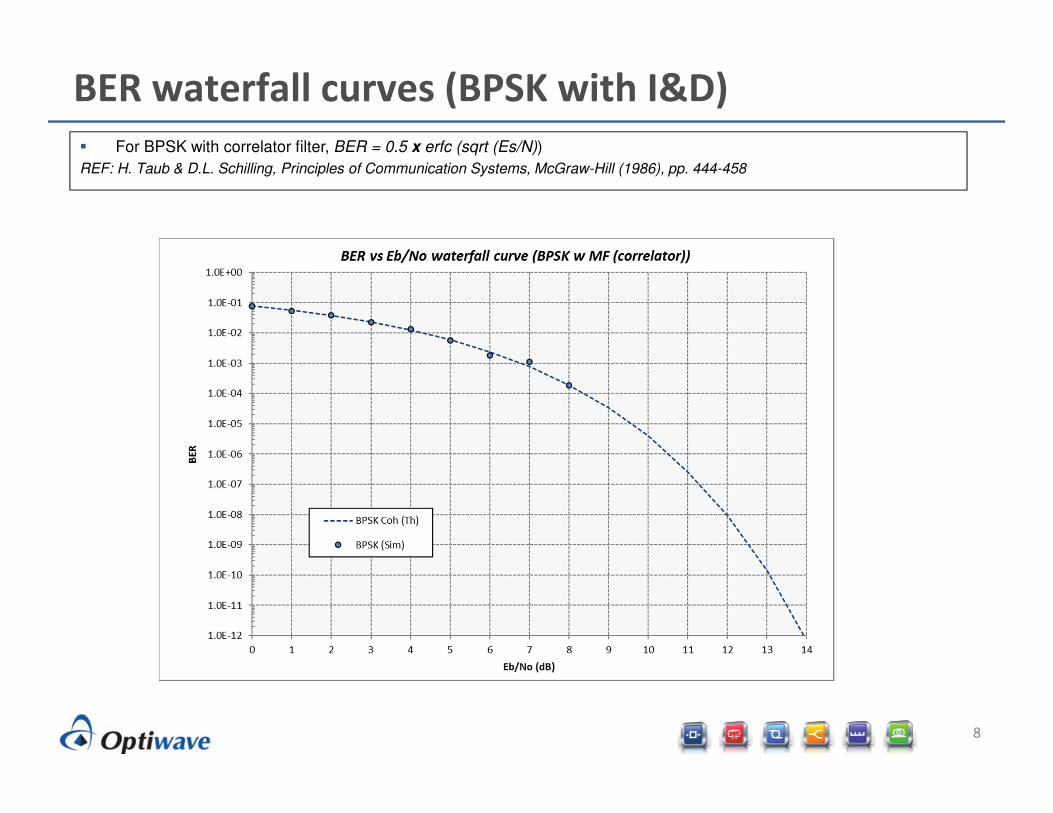
BER waterfall curves (BPSK with I&D)
� For BPSK with correlator filter, BER = 0.5 x erfc (sqrt (Es/N))
REF: H. Taub & D.L. Schilling, Principles of Communication Systems, McGraw-Hill (1986), pp. 444-458

9
BER waterfall curves (BFSK with I&D)
� For BFSK with matched filter, BER = 0.5 x erfc (sqrt (Es/2N))
REF: H. Taub & D.L. Schilling, Principles of Communication Systems, McGraw-Hill (1986), pp. 444-458

10
BER waterfall curves (ASK with RRC matched filters)
� BER vs. Eb/No results are shown for roll off factors of 0, 0.5 and 1.
� The BER performance for an ASK system with rectangular filter with BW = 1/2T is equal to 0.5 x erfc (sqrt (Es/2N)). As the roll off factor is increased (increased truncation of the time-domain RRC pulse) the BER performance against white noise
degrades due to the reduction of the eye opening