Embed Size (px)
Citation preview

1
OPTIMUM PIEZOELECTRIC BENDING BEAM STRUCTURES FOR ENERGY HARVESTING USING SHOE INSERTS
Loreto Mateu and Francesc Moll. Department of Electronic Engineering, Polytechnical University of Catalonia. C/ Jordi Girona s/n, Barcelona, 08034.
Abstract— The small amount of power demanded by many present-day electronic devices, opens the possibility to convert part of the energy present in the environment into electrical energy, using several methods. One of such methods is to use piezoelectric film bending beams inside the shoe, and use part of the mechanical energy employed during normal walking activity. This work analyzes several bending beam structures suitable for the goal application (shoe inserts and walking-type excitation) and obtains the resulting strain for each type in function of their geometrical parameters and material properties. As a result, the optimum configuration can be selected. Key Word — energy harvesting, piezoelectric films, bending beams, maximum deflection, power generation.
I. INTRODUCTION HE trends in technology allow the decrease in both size and power consumption of complex digital
systems. This decrease in size and power gives rise to the concept of wearable devices in which digital systems are integrated in everyday personal belongings, like clothes, watch, glasses, etc... Batteries are the power source used for wearable devices. However, the disadvantage of batteries is the need to either replace or recharge them periodically. An alternative to batteries is harvesting energy from the environment (energy harvesting).
PVDF films have been employed (Kendall, 1998; Kymissis, 1998; Starner 2004; Shenck 1999; Shenck 2001) in order to harvest electrical power from human walking activity. Roundy (2004) presented a piezoelectric cantilever beam in order to harvest the maximum electrical power available from a vibrational source. However, different structures were not thoroughly compared.
This article is an exhaustive and meticulous study of different piezoelectric beam structures. In every case it has been analysed their advantages and disadvantages. The final application is an assembly of a piezoelectric bending beam in the insole of a shoe in order to convert mechanical human walking activity into electric power.
The differences between the analysed piezoelectric beams can be grouped by shape, employed materials and its position, the kind of supports and restrictions because of the space available for the application. It is obtained for each analysed structure case the average strain of the beam in order to calculate the average power generated by human walking activity.
The structure of the work is as follows: Section II shows piezoelectric constitutive equations for PVDF and analyses the fact that in piezoelectric films, the excitation mode 31 is more efficient than mode 33. However, the force exerted by walking is in the 3 (z axis) direction. One way to circumvent this problem is to use bending beam structures to cause a stress in direction 1 when a force in direction 3 is applied. Section III and Section IV analyse different bending beam structures in order to select the most appropriate one to the application. Two kinds of beams are analysed: piezoelectric multimorphs and heterogeneous bimorphs (Smits, 1991). Piezoelectric bimorphs are made up of two piezoelectric films, one in each side of the neutral axis. These piezoelectric beams can be connected in parallel in order to add currents, or in series to add voltages. On the other hand, heterogeneous bimorphs consist of piezoelectric elements and a non-piezoelectric element that only provides the elastic function. Inside this group two kinds are considered. The first kind consists of a structure of a non-piezoelectric element sandwiched between piezoelectric films, and we call this structure symmetric heterogeneous bimorph. The second kind is made up of one or more piezoelectric films on top a non-piezoelectric material (Eggborn, 2003), and it is named as asymmetric heterogeneous bimorph. In these sections it is also examined the possibility to limit the deflection of the beam to a given value in accordance with the restrictions of space and comfort of the application. Section V shows the electrical power converted from mechanical activity for the different structures analysed previously. Section VI presents a comparison of the analysed beams to select the optimum configuration. Finally, Section VII draws some conclusions from the previous analysis
II. CONSTITUTIVE EQUATIONS FOR PVDF PVDF, polyvinylidene fluoride, is a piezoelectric polymer with mm2 crystal symmetry. Due to this
fact the piezoelectric constitutive equations shown in Equation (1) (Wanders) are simplified to Equation (2) (Ikeda, 1990) .
T

2
[ ] [ ][ ] [ ][ ][ ] [ ][ ] [ ][ ]
3,2,1m,l,k,i 6,...,1n,jnT lndmE lmlD
kE ikdjT ijsiS
==
+ε=
+=
Equation (1)
where repeated subscripts in the products imply a summation over the different components. T, applied mechanical stress [N/m2]. E, applied electric field. d, piezo strain tensor [(C/m2)/(N/m2)]. ε, permittivity tensor. D, electric displacement [C/m2]. S, mechanical strain.
Subscripts correspond to the direction of the axes as shown in Figure 1.
=
ε 3
3
2
1
3
3
2
1
33333231
33332313
32232212
31131211
DSSS
ETTT
ddddsssdsssdsss
=
ε 2
4
2
4
2224
2444
DS
ET
dds
Equation (2)
=
ε 1
5
1
5
1115
1555
DS
ET
dds
6666 STs =
Figure 1. Axes and directions for piezoelectric constitutive equations of piezoelectric materials.
PVDF films are only metallized in the plane perpendicular to 3 direction, so that D1=D2=0. Equation (3) reflects this assumption when no external electrical field is applied.
3332321313 TdTdTdD ++= Equation (3)
There are three possible modes to use PVDF films: 31 mode, 32 mode and 33 mode. 32 mode is discarded since d32 is ten times less than d31 or d33 (Brown, 20002). In mode 31, the stress is applied in 1 direction, and in mode 33, the stress is applied in 3 direction. The obtained voltage or charge resulting from an applied force in a certain direction, F1 or F3, is shown in Table 1.
In a thin PVDF film, the ratio L/H is on the order of 1000, while d31=23x10-12 m/V and d33=-33x10-12 m/V (Measurement Specialties). Therefore, it is seen from Table 1 that 31 mode has a more efficient electro-mechanical coupling factor than 33 mode.

3
A piezoelectric film placed inside a shoe as shown in Figure 5 would receive a stress applied in 3 direction. Therefore, a mechanical coupling is necessary to transform the stress applied in 3 direction to a stress in 1 direction. This problem is solved using bending beams.
Mode 31 Mode 33
Vo WF
g 131 H
WLF
g 333
q HLF
d 131 333Fd
Table 1. Voltage, Vo, and charge, q, obtained in the plane perpendicular to direction 3 applying a mechanical stress in direction 1, mode 31, and in direction 3, mode 33.
III. CANTILEVERS WITH LIMITED MAXIMUM DEFLECTION There are different kinds of bending beams depending on their supports, their shape, the position of
the applied point load or distributed load, etc (Young, 2002; Senturia, 2001; Beer, 1993; Yee, 2003). Moreover, beams can have one or multiple layers of different types of materials. For usual values of the forces applied, maximum deflection calculated is greater than the height available between beam and the insole of the shoe. Therefore, the assembly conditions limit the maximum attainable deflection.
Section A analyses the relation between average strain and maximum deflection for homogeneous cantilevers with an applied point load in x = L whereas section B analyses the case for heterogeneous cantilevers.
A. Triangular Vs. Rectangular Homogeneous Cantilever The beam that offers the maximum average strain for a given applied force, F, is the cantilever. The
average strain for an homogeneous beam, Figure 2, with any type of support employed is given by Equation (4) and it is defined as net strain along axis 1 (length), x, and axis 3 (thickness), z.
( )dzdxxz
L1
2tcS
2t
0
L
0caverage
c
∫ ∫ ρ= Equation (4)
where ρ(x) is the radius of curvature of the bending beam, and c is a constant that determines if the two piezoelectric films are wired in parallel, c = 2, or in series, c = 1.
The value of c depends on the way the two piezo films shown in Figure 2 are connected. If they are connected in parallel, the charge generated is due to the strain of both films, and they must be added,
2c = . For a series connection, the charge generated is only due to one of the film strain, c = 1.
Figure 2. Cross section of homogeneous bimorph beam. tc/2 corresponds to a piezoelectric film thickness. Yc is the Young’s modulus for the piezoelectric material. W0 is the width of the beam. The neutral axis is placed between the two piezoelectric films.
Figure 3 and Figure 4 show how the connection has to be done in order to establish the value of parameter c depending on poling axis orientation between piezoelectric films that are being tensed and compressed.
If the cantilever is triangular (Kendall 1998), its width varies as expressed in Equation (5),
( )
−=
Lx1WxW 0 Equation (5)
where W0 is the base of the triangle and L is the length of the beam and the height of the triangle.

4
Figure 3. Connection between the top and bottom piezoelectric films in order to add currents or voltages when the poling axis are identically oriented.
Figure 4. Connection between the top and bottom piezoelectric films in order to add currents or voltages when the poling axis are opposed.
Table 2 shows the average strain, Sx, deflection in function of x position, y(x), and maximum deflection, ymax, of the cantilever beam. Maximum deflection of the cantilever beam occurs when x = L.
Triangular cantilever Rectangular cantilever
Sx 2cmax
2c0c L2
cty
tWYcFL3 = 2
cmax2c0c L
ty8c3
tWY2cFL3 =
( )xy 3c0c
2
tWYFLx6
−
L3x1x
tWYFL6 2
3c0c
maxy 3c0c
3
tWYFL6 3
c0c
3
tWYFL4
Table 2. Average strain, Sx, deflection, y(x), and maximum deflection, ymax, for triangular cantilever and rectangular cantilever are shown in this table where tc is the thickness, W0 the width for rectangular beam and the base of the width for triangular beam, F is the point load applied over the position x = L and Yc is the PVDF Young’s modulus.
In the case of a triangular cantilever, the radius of curvature of the cantilever is constant along its length, which implies that the strain along x direction is also constant.

5
Figure 5. Cantilever assembly in the insole of the shoe with a limited deflection, D.
As can be seen in these expressions, cantilever with a triangular shape width suffers more strain than a cantilever with a rectangular shape width for identical load. The rectangular cantilever average strain is 75 % of the triangular cantilever average strain, expressed as a function of maximum deflection. Therefore, triangular cantilever would be preferred for a shoe insert, as was pointed out in Shenck (1999). A mechanical device must be placed inside the shoe in order to apply all the stress generated by human walking activity on the position x = L.
The height between the piezoelectric beam and the insole of the shoe is limited to D as can be shown in Figure 5. Therefore, maximum deflection, ymax, that appears in the equations of Table 2 must be substituted by D.
B. Triangular Heterogeneous Cantilever The maximum strain in a beam takes place at its surface, at z = tc/2 and z = -tc/2. One way to increase
the average strain for the piezoelectric film, and therefore, the harvested power, is to increase the beam thickness. This can be done keeping the same amount of piezoelectric material using heterogeneous bimorphs composed of non-piezoelectric films and piezoelectric films as can be seen in Figure 6 and Figure 7.
The neutral axis for a composite beam is calculated with the general expression of Equation (6).
∑
∑
=
== n
1ii
r
i
n
1ii
r
ii
s
AYY
AYYz
z Equation (6)
where n is the number of layers of different materials, zi is the height for layer i, Yi is the Young’s modulus for layer i, Yr is the Young’s modulus for layer r and Ai is the area of cross section for layer i.
Figure 6. Cross section of symmetric heterogeneous bimorph beam. tc/2 corresponds to piezoelectric film thickness whereas ts corresponds to non-piezoelectric film thickness. Yc is the Young’s modulus for the piezoelectric material, and Ys is the Young’s modulus for the non-piezoelectric material. W0 is the width of the beam.
Figure 7. Cross section of asymmetric heterogeneous bimorph beam. tc corresponds to a piezoelectric film thickness whereas ts corresponds to a non-piezoelectric film thickness. Yc is the Young’s modulus for the piezoelectric material and Ys is the Young’s modulus for the non-piezoelectric material. W0 is the width of the beam.

6
Figure 6 (Eggborn, 2003) shows a symmetric heterogeneous bimorph whereas Figure 7 shows an asymmetric heterogeneous bimorph. In both structures the respective dimensions of piezoelectric films and non-piezoelectric film are the same.
Homogeneous
Bimorph Symmetric Heterogeneous Bimorph Asymmetric Heterogeneous Bimorph
Sx 2cmax
L2
tyc
+ s
c2
max t2t
L
cy
( )( )sscc
2scssmax
YtYtL
tttYy
+
+
maxy 3c0
3
tYWFL6 ( )( )3
ss2scs
2c
3cc0
3
tYtt3tt3tYWFL6
+++ ( )
( )( )2ssc
2cscsc
4s
2s
4c
2c0
sscc3
t2tt3t2ttYY2tYtYWYtYtFL6
+++++
zs 2t c
2tt sc +
c
c
ss
csc
c
s2s
tYY
t
2t
ttYY
2t
+
++
Table 3. Equations of average strain, Sx, maximum deflection, ymax, and neutral axis position, zs. The analysed cantilevers have triangular width.
Figure 8. Average strain for asymmetric and symmetric heterogeneous bimorph triangular cantilever with L = 171 mm, D = 7 mm, tc = 100 µm, and ts = 1 mm .
Symmetric heterogeneous bimorph is independent of Young’s modulus whereas asymmetric heterogeneous bimorph is dependent of Yc and Ys, as shown in Figure 8. For a ratio Ys/Yc smaller than 2, symmetric heterogeneous bimorph strain with c = 1 is greater than asymmetric heterogeneous bimorph strain. However, for a ratio Ys/Yc greater than 2, asymmetric heterogeneous bimorph strain leads symmetric heterogeneous bimorph strain with c=1. For any value of the ratio Ys/Yc, symmetric heterogeneous bimorph with films connected in parallel (c=2) is greater than the other configurations.
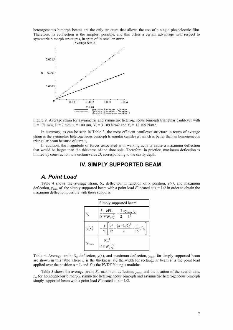
The resulting strain is also dependent on the thickness of the non-piezoelectric material, ts, as shown in Figure 9. For the material values considered in the calculation, asymmetric heterogeneous bimorph is slightly greater than symmetric heterogeneous bimorph with c = 1. Symmetric heterogeneous bimorph with c = 2 is greater than the other simulated bimorphs and linearly dependent of ts, as was the case with symmetric heterogeneous bimorph with c = 1.
The neutral axis for the symmetric heterogeneous bimorphs is located in the middle of the thickness whereas the location of the neutral axis for the asymmetric heterogeneous bimorphs depends on the thickness of the piezoelectric and the non-piezoelectric films and their respective Young’s modulus.
If tc is defined as the thickness of a piezoelectric film that is made with only one piezoelectric film, from z = 0 to z= tc/2 the film is compressed and from z = 0 to z = -tc/2 the film is tensed and so, the average strain is zero and no power is harvested from walking activity. To obtain a net charge for a piezoelectric beam is necessary a bimorph structure in order to add charge or voltage for the film compressed and the film tensed. In this case the neutral axis is between both films. Hence asymmetric
7
heterogeneous bimorph beams are the only structure that allows the use of a single piezoelectric film. Therefore, its connection is the simplest possible, and this offers a certain advantage with respect to symmetric bimorph structures, in spite of its smaller strain.
Figure 9. Average strain for asymmetric and symmetric heterogeneous bimorph triangular cantilever with L = 171 mm, D = 7 mm, tc = 100 µm, Yc = 3·109 N/m2 and Ys = 12·109 N/m2.
In summary, as can be seen in Table 3, the most efficient cantilever structure in terms of average strain is the symmetric heterogeneous bimorph triangular cantilever, which is better than an homogeneous triangular beam because of term ts.
In addition, the magnitude of forces associated with walking activity cause a maximum deflection that would be larger than the thickness of the shoe sole. Therefore, in practice, maximum deflection is limited by construction to a certain value D, corresponding to the cavity depth.
IV. SIMPLY SUPPORTED BEAM
A. Point Load Table 4 shows the average strain, Sx, deflection in function of x position, y(x), and maximum
deflection, ymax, of the simply supported beam with a point load F located at x = L/2 in order to obtain the maximum deflection possible with these supports.
Simply supported beam
Sx 2cmax
2c0 L
tcy23
tYWcFL
83 =
( )xy
−
−−− xL
161
62Lx
12x
YIF 2
33
maxy 3c0
3
tYW4FL
Table 4. Average strain, Sx, deflection, y(x), and maximum deflection, ymax, for simply supported beam are shown in this table where tc is the thickness, W0 the width for rectangular beam F is the point load applied over the position x = L and Y is the PVDF Young’s modulus.
Table 5 shows the average strain, Sx, maximum deflection, ymax, and the location of the neutral axis, zs, for homogeneous bimorph, symmetric heterogeneous bimorph and asymmetric heterogeneous bimorph simply supported beam with a point load F located at x = L/2.

8
Homogeneous Bimorph
Symmetric Heterogeneous Bimorph Asymmetric Heterogeneous Bimorph
Sx 2cmax
L
tcy23
+ s
c2max t
2t
L
cy3 ( )
( )sscc2
scssmaxYtYtL
tttYy3
+
+
maxy 3c0
3
tYW4FL ( )( )3
ss2scs
2c
3cc0
3
tYtt3tt3tYW4
FL
+++ ( )
( )( )2ssc
2cscsc
4s
2s
4c
2c0
sscc3
t2tt3t2ttYY2tYtYW4
YtYtFL
++++
+
zs 2tc
2tt sc +
cc
ss
csc
c
s2s
tYY
t
2t
ttYY
2t
+
++
Table 5. Equations of average strain, Sx, maximum deflection, ymax, and neutral axis position, zs. The analysed simply supported beam has rectangular width.
B. Distributed load
Figure 10. Simply supported beam with a limited maximum deflection. The beam with length L is deflected by a mass with a length Lm and causes a deflection enough to cause a contact between the beam beneath the mass and the insole of the shoe.
A simply supported beam with a maximum deflection for a given force greater than the height of the structure can be interpreted as equivalent to a double cantilever as it is explained in this section. The simply supported beam is deflected by a mass with a length Lm. It can be considered that the part of the beam that doesn’t touch the insole is the one that is not under the mass. Therefore, the mass acts as fixed support and the pinned support is equivalent to a force that acts over the cantilever in order to deflect it. This is the equivalence between simply supported beam and cantilevers in this case.
Figure 11. Cantilever of length L’ with a point load, F, at x = L’. The left end of the cantilever is free-ended whereas the right end of the cantilever is fixed.
Figure 11 represents a cantilever with a point load at x = L’. Table 6 gives the expression of average strain in function of its maximum deflection, that appears in Equation (7), for homogeneous bimorph, symmetric heterogeneous bimorph and asymmetric heterogeneous bimorph cantilevers.
YI3FLy
3'max = Equation (7)
The addition of two cantilevers gives as result the simply supported beam shown in Figure 10. Table 7 gives the expression of average strain in function of the fixed height, D, for homogeneous
bimorph, symmetric heterogeneous bimorph and asymmetric heterogeneous bimorph simply supported beam. Equations of Table 7 have been derived from equations of Table 6 taking into account that the simply supported beam analysed is made up of two cantilevers each one with a length (L-Lm)/2.

9
Homogeneous Bimorph Symmetric Heterogeneous Bimorph
Asymmetric Heterogeneous Bimorph
Sx 2'cmax
L8
tcy3
+ s
c2'
max t2t
L4
cy3
+ s
c2'
max t2t
L4
cy3
Table 6. Equations of average strain, Sx, for a cantilever with a point load, F, placed at x = L. The beam has rectangular width.
Homogeneous Bimorph Symmetric Heterogeneous Bimorph
Asymmetric Heterogeneous Bimorph
Sx ( )2m
c
LL
cDt3
− ( )
( )2m
sc
LL
t2tcD6
−
+ ( )( ) ( )sscc
2m
scss
YtYtLL
tttDY6
+−
+
Table 7. Equations of average strain, Sx, for the simply supported beam of Figure 10.
The simply supported beam with distributed load average strain equations is valid for the conditions mentioned in this section. Figure 12 shows average strain for the different types of support here analysed, as a function of the mass length of the distributed load, Lm. It can be seen that the case of distributed load always presents a larger average strain than the other cases.
Figure 12. Average strain for homogeneous bimorph cantilever, simply supported beam with point load and distributed load. The parameters values are L = 171 mm, D = 7 mm, tc = 100 µm, and c = 2.
V. ELECTRICAL POWER HARVESTED The average power harvested from human walking activity (Kendall 1998; Starner 2004; Paradiso
2004), shown in Equation (8), has its maximum value when Equation (9) is verified. Equation (10) expresses the value of the maximum average power in function Ceq.
( )( )22
eq2
2x31
2p
RC12RASe
R2
VP
ω+ω
== Equation (8)
eqC1R ω= Equation (9)
eq
22x
231
max C4ASe
Pω
= Equation (10)
where A is the area of piezoelectric material, Ceq is the equivalent capacitance of the piezoelectric films, which depends on the film dimensions as well as their connection, Sx is the average strain, ω is the angular frequency of the sinusoidal wave that is considered as mechanical excitation, and |Vp| corresponds to the modulus of the peak voltage for the sinusoidal wave.
All the analysis done assume that walking activity responds to a sinusoidal wave. While this assumption is only approximate, it can be useful to compare the different structures. A more realistic power calculation will be developed in the near future.

10
The area A can be calculated as the area of one piezoelectric film.
LWA 0= Equation (11)
Ceq is the equivalent capacitance for the connection made with the piezoelectric films employed. The piezoelectric films can be wired in series or in parallel. The equivalent capacitance for bimorphs and symmetric heterogeneous bimorphs is the same and it can be shown in Table 8 joined up with equivalent capacitance for asymmetric heterogeneous bimorphs.
Homogeneous and Symmetric
Heterogeneous Bimorph Asymmetric Heterogeneous Bimorph
Ceq c
2
tAc ε
ctAε
Table 8. Equivalent capacitor for bimorphs, symmetric heterogeneous bimorphs and asymmetric heterogeneous bimorphs.
Table 9 shows the relation between the connection of homogeneous and symmetric heterogeneous bimorph piezoelectric films and the charge and voltage generated.
Homogeneous and Symmetric
Heterogeneous Bimorph Asymmetric Heterogeneous Bimorph
q AcD3 AD3
V ct
E c3 c3tE
pV 22eq
2
x31
RC1
RASe
ω+
ω
22eq
2
x31
RC1
RASe
ω+
ω
Table 9. Equivalent charge, voltage and peak voltage modulus for bimorphs, symmetric heterogeneous bimorphs and asymmetric heterogeneous bimorphs.
maxP
Homogeneous Bimorph ε
ω3
03c
2max
231
2c
L16WtydY
Symmetric Heterogeneous Bimorph
( )ε
ω+3
02
scc2max
231
2c
L4Wt2ttydY
Asymmetric Heterogeneous Bimorph
( )( )2
sscc3
02
sc2s
2sc
2max
231
2c
YtYtL4WtttYtydY
+εω+
Table 10. Maximum average power for triangular cantilever with point load applied at x = L.
maxP
Homogeneous Bimorph ε
ω3
03c
2max
231
2c
L16WtydY9
Symmetric Heterogeneous Bimorph
( )ε
ω+3
02
scc2max
231
2c
L4Wt2ttydY9
Asymmetric Heterogeneous Bimorph
( )( )2
sscc3
02
sc2s
2sc
2max
231
2c
YtYtL4WtttYtydY9
+εω+
Table 11. Maximum average power for simply supported beam with point load applied at x = L/2.

11
From equations given in Table 10, Table 11, and Table 12, it can be derived the appropriate dimensions of the structure and its elastic and piezoelectric properties. It is recommended a small length and a large width and thickness. The most suitable PVDF film would be the one with large Young’s modulus, Yc, and piezo strain constant, d31, but with little permittivity, ε. Moreover, the maximum average power depends linearly with the walking frequency and with the limited height D.
maxP
Homogeneous Bimorph ( ) ε−ω
4m
03c
2max
231
2c
LL4LWtydY9
Symmetric Heterogeneous Bimorph
( )( ) ε−
ω+4
m
02
scc2max
231
2c
LLLWt2ttydY9
Asymmetric Heterogeneous Bimorph
( )( ) ( )2
sscc4
m
02
sc2s
2sc
2max
231
2c
YtYtLLLWtttYtydY9
+ε−ω+
Table 12. Maximum average power for simply supported beam with distributed load.
VI. COMPARISON OF STRUCTURES It was presented in the previous sections a detailed analysis of several structures suitable for shoe
inserts. In summary, the structures considered can be classified according to two properties. One of them is vertical structure (homogeneous bimorph, and symmetric or asymmetric heterogeneous bimorph). The second property is the kind of support: cantilever with a triangular horizontal shape for maximum efficiency, and simple support at both ends, either with a point load, or a distributed load.
Homogeneous Bimorph Symmetric Heterogeneous
Bimorph Asymmetric Heterogeneous Bimorph
Sx cS1
+
c
s1 t
t21cS
cscs
cs
c
s
c
s1 YYtt1
tt1YY
tt
S2+
+
maxP 1P 2
c
s1 t
t21P
+
2
cscs
cs2
c
s2
c
s1 YYtt1
tt1YY
tt
4P
+
+
Table 13. Average strain and power general equations that express the relation between homogeneous bimorph, symmetric heterogeneous bimorph and asymmetric heterogeneous bimorph.
From the expressions obtained and shown in Tables 2 to 12, it can be observed that the relation between obtained strain and power for the three vertical structures considered is always the same, independently of the kind of support used. Let us then denote by S1 and P1 the strain and power of the homogeneous bimorph structure. Table 13 shows the strain and power for the other structures. Their relation can be observed graphically in Figure 13 and Figure 14, in function of non-dimensional magnitudes ts/tc and Ys/Yc. From this figure, it can be concluded that the most efficient vertical structure is the asymmetric heterogeneous bimorph with a large value of Ys/Yc.
Triangular cantilever Simply supported beam with point load
Simply supported beam with distributed load
Sx 2S 2S3 ( ) 22m
SLL1
6
−
maxP 2P 2P9 ( ) 24m
PLL1
36
−
Table 14. Average strain general equations that express the relation between triangular cantilever, simply supported beam with point load and simply supported beam with distributed load.

12
Figure 13. Average strain general relation for homogeneous bimorph, symmetric heterogeneous bimorph and asymmetric heterogeneous bimorph.
Figure 14. Average power general relation for homogeneous bimorph, symmetric heterogeneous bimorph and asymmetric heterogeneous bimorph.
With regard to the kind of support, Table 14 summarizes the expressions for strain and power for the homogeneous bimorph in function of those corresponding to a triangular cantilever. It is seen from this table that the most efficient support is in general the simply supported beam with distributed load.
Therefore, the optimum selection for the studied piezoelectric inserts is the asymmetric heterogeneous bimorph with a simply supported beam with distributed load. The bigger the ratio Ys/Yc, the better the average generated power will be.
VII. CONCLUSIONS It was analytically shown in this work how to construct an optimum beam-type shoe insert in terms
of its vertical structure and the kind of support to use. It was taken into account in this analysis that under normal walking type excitation, the force exerted on the insert is strong enough, given the usual piezoelectric film elastic properties, to cause a deflection limited by the shoe cavity dimensions where the insert is to be placed. Therefore, the cavity dimension itself is also a factor to consider. From the linear

13
analysis performed, it is concluded that the deeper this cavity is, the better. Other factors as walking comfort or facility of construction should also be evaluated.
The conclusions presented are useful to guide the construction of a prototype, which must validate experimentally this analysis. Also as future work, a more detailed evaluation of the harvested energy in function of the usual gait excitation is necessary.
ACKNOWLEDGMENTS The authors gratefully acknowledge Prof. Joseph A. Paradiso from the Massachusetts Institute of
Technology, Prof. Shad Roundy from Australian National University R. Brown from Measurement Specialties for kindly answering our questions. This work has been partially supported by the Spanish Ministry of Science and Technology and the Regional European Development Funds (FEDER) from the European Union through project TIC2001/2337.
BIBLIOGRAPHY Beer, F. P. and E. R. Johnston. 1993. “Mecánica de materiales”. McGraw-Hill. Brown, R. 2002. Private correspondence with R. Brown. Measurement Specialties. Eggborn, T. 2003. “Analytical Models to Predict Power Harvesting with Piezoelectric Materials”. MSc thesis, Virginia Polytechnic Institute and State University, Blacksburg, Virginia. Ikeda, T. 1990. “Fundamentals of Piezoelectricity”. Oxford Science Publications. Kendall, C. 1998. “Parasitic Power Collection in Shoe Mounted Devices”. BSc thesis. Massachusetts Institute of Technology, Massachusetts. Kymissis, J., C. Kendall, J. Paradiso and N. Gershenfeld. 1998. “Parasitic Power Harvesting in Shoes”. Second IEEE International Conference on Wearable Computing, pages 132–139. Measurement Specialties. Piezo Film Sensors. Technical Manual. http://www.msiusa.com Paradiso, J. 2004. Private correspondence with J. Paradiso. Massachusetts Institute of Technology, Massachusetts. Roundy, S., P. K. Wright and J. Rabaey. 2004. “Energy Scavenging for Wireless Sensor Networks with Special Focus on Vibrations”. Kluwer Academic Publishers. Senturia, S. D. 2001.“Microsystem Design”. Kluwer Academic Publishers. Shenck , N. 1999. “A demonstration of useful electric energy generation from piezoceramics in a shoe”. MSc thesis. Massachusetts Institute of Technology, Massachusetts. Shenck, N. and J. Paradiso. 2001.“Energy Scavenging with Shoe-Mounted Piezoelectrics”. IEEE Micro, 21(3):30–42. Smits, J. G. and W. Choi. 1991. “The Constituent Equations of Piezoelectric Heterogeneous Bimorphs”. IEEE Transactions on Ultrasonics, Ferroelectrics, and Frequency Control, 38(3):256-270. Starner, T. and J. Paradiso. 2004. “Human Generated Power for Mobile Electronics”. Wanders, J. W. “Piezoelectric ceramics. Properties and Applications”. Philips components. Yee, J. K. 2003. “Shock Resistance of Ferromagnetic Micromechanical Magnetometers”. MSc thesis, University of California, Los Angeles. Young , W. C. and R. G. Budynas. 2002. “Roark’s Formulas for Stress and Strain”. McGraw-Hill.
BIOGRAPHY Loreto Mateu received her MSc in Electronic Engineering from Politechnical University of
Catalonia in 2002. Nowadays, she is a PhD student in the Department of Electronic Engineering, Polytechnical University of Catalonia, Spain. Her area of research is energy harvesting to power wearable devices. She has focused in piezoelectric materials, thermoelectric generators and electromagnetic power conversion. Moreover, she is also interested in DC-DC converters to power wearable devices from electrical energy harvested.
Francesc Moll received the equivalent to MSc degree in Physics from the University of Balearic Islands (UIB), Spain, in 1991, and the PhD degree in Electronic Engineering from the Polytechnical University of Catalonia (UPC), Spain, in 1995. From 1991 he has been with the Department of Electronic Engineering, Polytechnical University of Catalonia, Spain, where he is currently an associate professor. His current research activities involve methods for energy harvesting oriented to low power RF communication devices. Other research interests include interconnection and packaging characterization and modelling, and crosstalk and noise effects in integrated circuits.


![Topology Optimum Design of Piezoelectric Energy Harvesting ...Gil Ho Yoon [7] developed optimal layouts for piezoelectric energy harvesting devices by considering the harmonic dynamic](https://img.dokumen.tips/doc/110x75/6114a1b26c4e6600b33777c8/topology-optimum-design-of-piezoelectric-energy-harvesting-gil-ho-yoon-7-developed.jpg)