Embed Size (px)
Citation preview

Farkas,J., Jármai,K., Virág,Z.: Optimum design of a belt-conveyor bridge constructed as a
welded ring-stiffened cylindrical shell, 56th Annual Assembly of International Institute of
Welding, July 6-10, 2003, Bucharest, IIW-Doc. XV-1144-03, XV-WG9-23-03, 12 p.
Optimum design of a belt-conveyor bridge constructed as a
welded ring-stiffened cylindrical shell
Farkas,J., Jármai,K., Virág,Z.
University of Miskolc, Hungary
Abstract
In the structural optimization of a ring-stiffened cylindrical shell the unknown variables are the
shell thickness as well as the thickness and the number of flat rings. The shell diameter enables to
realize a belt-conveyor structure inside of the shell. The uniformly distributed vertical load consists
of dead and live load. The design constraints relate to the local shell buckling strength, to the panel
ring buckling and to the deflection of the simply supported bridge. The cost function includes the
material and fabrication costs. The fabrication cost function is formulated according to the
fabrication sequence and includes also the cost of forming of shell elements into the cylindrical
shape as well as the cost of cutting of the flat plate ring-stiffeners. Since the shell thickness does not
depend on number of ring-stiffeners (n), the nopt is calculated for a selected region of n.
IIW-Thesaurus keywords:
structural optimization, shell buckling, welded stiffened shells, welded structures, fabrication costs
___________________________________________________________________________
IIS/IIW- (ex.doc. XV-1144-03) recommended for publication by IIW Commission XV "Design,
analysis and fabrication of welded structures"
brought to you by COREView metadata, citation and similar papers at core.ac.uk
provided by Repository of the Academy's Library

List of symbols
Ar cross-sectional area of a ring stiffener
AT thermal impulse due to welding
Aw cross-sectional area of a weld
C coefficient Eq. 17
c0 specific heat
E elastic modulus
fy yield stress
hr stiffener height
I arc current
Ir moment of inertia of a ring stiffener
Ix moment of inertia of the shell cross-section
K cost
KM material cost
KF fabrication cost
kM material cost factor
kF fabrication cost factor
L span length
Le shell effective width
Lr distance of rings
M bending moment
n number of ring stiffeners
p factored load intensity
p0 unfactored load intensity
QT specific heat input caused by welding
R shell radius
R0 radius Figure 1
Ta, Tb times Table 1
t thickness
tr ring stiffener thickness
U arc voltage
umax maximal radial deformation
V volume
vw welding speed

w deflection
yG distance of the gravity centre
Z factor Eq.17
0 coefficient of thermal expansion
β reduction factor Eq.15
0 coefficient of thermal efficiency
κ number of elements to be assembled
Θ difficulty factor
λ Eq.6
ρ material density
0 factor Eq.18
σ normal stress
E buckling stress
cr critical buckling stress
ψ coefficient Eq.18
ω quotient Eq.21
1. Introduction
Stiffened shells are widely used in offshore structures, bridges, towers, etc. Rings and/or stringers
can be used to strengthen the shape of cylindrical shells. Shells can be loaded by axial compression,
bending, external or internal pressure or by combined load.
Design rules for the shell buckling strength have been worked out by ECCS [1], API [2] and
DNV [3]. The optimum design of stiffened shells has been treated in some of our articles [4, 5, 6].
The optimum design of a stiffened shell belt-conveyor bridge has been treated in [7]. The buckling
behaviour of stiffened cylindrical shells has been investigated by several authors, e.g. Harding [8],
Dowling and Harding [9], Ellinas et al [10], Frieze et al [11], Shen et al [12], Tian et al [13]
In the calculation of shell buckling strength the initial imperfections should be taken into
account. These imperfections are caused by fabrication and by shrinkage of circumferential welds.
A calculation method for the effect of welding has been worked out by the first author [14] and it is
used in the calculation of the local shell buckling strength.
In the present study the design rules of Det Norske Veritas (DNV) are used for ring-stiffened
cylindrical shells. The shape of rings is a simple flat plate, which is welded to the shell by double

fillet welds. In the calculation of the fabrication cost the cost of forming the shell elements into the
cylindrical shape and the cutting of the flat ring-stiffeners is also taken into account.
The shell is a supporting bridge for a belt-conveyor, simply supported with a given span
length of L = 60 m and radius of R = 1800 mm (Figures 1,2). The intensity of the factored
uniformly distributed vertical load is p = 16.5 N/mm + self mass. Factored live load is 12 N/mm,
dead load (belts, rollers, service-walkway) is 4.5 N/mm. For self mass a safety factor of 1.35 is
used, which is prescribed by Eurocode 3 (note that ECCS gives 1.3). The safety factor for variable
load is 1.5. The flat plate rings are uniformly distributed along the shell. Note that the belt-conveyor
supports are independent of the ring stiffeners, they can be realized by using local plate elements.
The unknown variables are as follows: shell thickness t, stiffener thickness tr and number of
stiffeners n.
We do not consider the case of an unstiffened shell, since to assure a stable cylindrical
shape, a certain number of ring-stiffeners should be used. In the present study we consider a range
of ring numbers n = 6 – 30. The range of thicknesses t and tr is taken as 4 – 20 mm, rounded to 1
mm.
2. The design constraints
2.1 Local buckling of the flat ring-stiffeners (Fig. 1.)
According to DNV
0.4r
r y
h E
t f (1)
Considering this constraint as active one, for E = 2.1x10⁵ MPa and yield stress fy = 355 MPa one
obtains
hr = 9tr. (2)
2.2 Constraint on local shell buckling (as unstiffened) (Fig. 3.)
16.5 1.35 (2 )rp R t nA ; 61085.7 x kg/mm3 ; Ar = hrtr (3)
8
2
max
pLM ; (4)

p
R
Lr
L
(a)
Le
Lr
hr
R
yG
R0
tr
t
G
(b)
Figure 1. (a) A simply supported belt conveyor bridge constructed as a ring stiffened cylindrical
shell, (b) the cross-section of a ring stiffener including the effective width of the shell
maxmax 2 41
y
cr
fM
R t
(5)
2
22 , 1.5 50
10.92
y
E
E r
f E tC
L
(6)
1
r
LL
n
(7)
The factor of (1.5-50 ) in Eq. (6) expresses the effect of initial radial shell deformation caused by
the shrinkage of circumferential welds and can be calculated as follows [14].
The maximum radial deformation of the shell caused by the shrinkage of a circumferential weld is
tRAu T /64.0max (8)
where ATt is the area of specific strains near the weld. According to our results [15]
0
03355.0
c
QtA T
T (9)

Figure 2. Cross-section of a belt conveyor bridge with two belt conveyors and a service walkway in
the middle.
For steels it is
TT QxtA 310844.0 (ATt in mm2, QT in J/mm) (10)
WA
W
T ACv
UIQ 0 (11)
For manually arc welded butt welds it is
WT AQ 7.60 (AW in mm2) (12)
When 10t mm, AW = 10t (13)
When t> 10 mm, 45.105.3 tAW (14)
Figure 3. Top-view of the shell with local buckling
Introducing a reduction factor of for which

02.04
01.0 max Rt
u (15)
and the imperfection factor for shell buckling strength should be multiplied by )505.1( .
For 0.01 0.01, for 0.02 0.02. (16)
Furthermore
2 2
01 , 0.9539 rLC Z
Rt
(17)
0.5
01, 0.702 , 0.5 1300
RZ
t
(18)
It can be seen that E does not depend on Lr , since in Eq. (6) Lr2 is in nominator and in C
(Eq.17) it is in denominator. The fact that the buckling strength does not depend on the shell length
is first derived by Timoshenko and Gere [16]. Note that API design rules [2] give another formulae.
On the contrary, in the case of external pressure the distance between ring-stiffeners plays an
important role [4,6].
2.3. Constraint on panel ring buckling (Fig. 4.)
Requirements for a ring stiffener are as follows:
2
20.06r r r rA h t L t
Z
(19)
43
max 01 4.
12 1 500
r rr
r
tRh tI
EL
(20)
0 ; ;2 1
erG G
r r
L thR R y y
h t
(21)
0min , 1.5e r eL L L Rt (22)
Figure 4. Top-view of panel ring buckling
2.4 Deflection constraint
4
0max
5
384 500x
p L Lw
EI (23)
3
xI R t (24)
The unfactored load is
p0 = 12/1.5 + 4.5/1.35 + (2 )rR t nA = 11.33 + (2 )rR t nA . (25)
3 The cost function
The cost function is formulated according to the fabrication sequence. A possible fabrication
sequence is as follows:
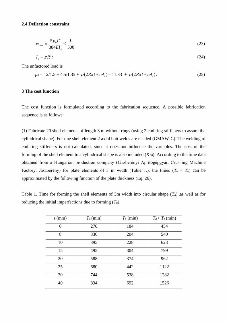
(1) Fabricate 20 shell elements of length 3 m without rings (using 2 end ring stiffeners to assure the
cylindrical shape). For one shell element 2 axial butt welds are needed (GMAW-C). The welding of
end ring stiffeners is not calculated, since it does not influence the variables. The cost of the
forming of the shell element to a cylindrical shape is also included (KF0). According to the time data
obtained from a Hungarian production company (Jászberényi Aprítógépgyár, Crushing Machine
Factory, Jászberény) for plate elements of 3 m width (Table 1.), the times (Ta + Tb) can be
approximated by the following function of the plate thickness (Eq. 26).
Table 1. Time for forming the shell elements of 3m width into circular shape (Ta) ,as well as for
reducing the initial imperfections due to forming (Tb).
t (mm) Ta (min) Tb (min) Ta+ Tb (min)
6 270 184 454
8 336 204 540
10 395 228 623
15 495 304 799
20 588 374 962
25 680 442 1122
30 744 538 1282
40 834 692 1526

2
0 (212.18 42.824 0.2483 )F FK k t t (26)
The cost of welding of a shell element is
3 2
1 1 1.3 0.2245 10 2 3000F FK k V x x t x
(27)
where is a difficulty factor expressing the complexity of the assembly and is the number of
elements to be assembled
12; 2 3000; 2V R tx (28)
The first term of Equation 27 expresses the time of assembly and the second calculates the time of
welding and additional works [18].
(2) Welding the whole unstiffened shell from 20 elements with 19 circumferential butt welds
3 2
2 120 1.3 0.2245 10 19 2F FK k V x x t x x R (29)
(3) Cutting of n flat plate rings with acetylene gas [17]
crccFF LtCkK25.0
3 (30)
where c , Cc and Lc are the difficulty factor for cutting, cutting parameter and length respectively,
c =3, Cc= 1.1388, 2 2c rL R n R h n .
(4) Welding n rings into the shell with double-sided GMAW-C fillet welds. Number of fillet welds
is 2n
3 2
4 21 1.3 0.3394 10 4F F WK k n V x x a x R n (31)
aW = 0.5tr, but aWmin = 3 mm. 2 120 22
rr r
hV V R h t n
(32)
aW is taken so that the double fillet weld joint be equivalent to the stiffener thickness.
The total material cost is 2M MK k V (33)
The total cost is 0 1 2 320( )M F F F FK K K K K K + KF4 (34)
kM = 1 $/kg; kF = 1 $/min
4. Results of the optimum design
The optimization has been worked out using the Hillclimb technique [18]. Results can be found in
Table 2. Those results for which the place of stiffeners coincides with the circumferential welds of
the shell segments are not applicable for fabrication reasons ( n = 9, 19).

Table 2. Computational results: the number of stiffeners, thickness of the stiffeners, material and
total costs in the case of optimum shell thickness t = 7 mm. The optimum solution is marked by
bold letters.
n tr KM K
6 21 39291 76041
7 19 39211 75870 8 18 39266 76296
9 17 39278 76531
10 16 39252 76595
11 16 39448 77640
12 15 39365 77446
13 15 39538 78384
14 14 39404 77965
15 14 39555 78803
16 13 39379 78191
17 13 39509 78935
18 13 39640 79679
19 12 39409 78819
20 12 39520 79476
21 12 39632 80132
22 12 39744 80787
23 11 39451 79646
24 11 39545 80222
25 11 39639 80796
26 11 39733 81370
27 11 39827 81943
28 10 39470 80505
29 10 39547 81005
30 10 39625 81505
Table 3. Cost distribution for the optimum solution
n tr 20 KF0 20 KF1 KF2 KF3 KF4 KM K 7 19 19991 4707 3459 1076 7425 39211 75870
20*KF0
26%KF2
5%
KF3
1%
KF4
10%
KM
52%
20*KF1
6%
Figure 5. Cost distribution for the optimum solution (t = 7, tr = 19, n = 7).
Table 3 shows the value of the different cost elements and Fig. 5 gives the percentage of them.

Conclusions
The shell thickness is determined by the constraints on local shell buckling as well as on deflection.
Since the number of ring-stiffeners does not influence these constraints, in order to assure a stable
circular shell shape, a certain number of rings should be used. Since the design rules do not give any
prescriptions for the minimum number of ring-stiffeners, for the investigated case we have selected
a ring number domain of n = 6 – 30 and have performed the optimization in this domain.
The Det Norske Veritas design rules give suitable formulae for the design of rings, the
dimensions of which decrease with the increase of the number of rings.
The initial radial deformation of the shell caused by the shrinkage of circumferential welds
affects the local shell buckling strength significantly. Cost calculation methods are proposed for the
forming of shell elements into circular shape and for the cutting of flat plate ring-stiffeners. The
cost function is formulated according to the fabrication sequence.
The optimization results (Table 2) show that, due to the cutting and welding costs of
stiffeners, the smaller number of stiffeners is more economic. The optimum ring number is 7, which
minimizes the total mass (material cost) and the total cost. Material cost is about half of the total
one and is insensitive to the variation of ring numbers. The forming cost of the shell elements (KF0)
is significant. The difference between the best and worst optima indicated in Table 2 is 7 %, thus it
is worth to use an optimization process in the design stage. The result is greatly dependent on local
situation, parameters, but this numerical evaluation and comparison show the benefit of optimum design.
Acknowledgements
The research work was supported by the Hungarian Scientific Research Foundation grants OTKA
T38058 and T37941.
References
1. European Convention of Constructional Steelwork (ECCS) Recommendations for Steel
Construction. Buckling of steel shells. No.56. Brussels, 1988.
2. American Petroleum Institute (API) Bulletin 2U. Bulletin on stability design of cylindrical shells.
2nd ed. Washington, 2000.
3. Det Norske Veritas (DNV): Buckling strength analysis. Classification Notes No.30.1. Hovik,
Norway, 1995.
4. Farkas,J., Jármai,K., Snyman,J.A., Gondos,Gy.: Minimum cost design of ring-stiffened welded
steel cylindrical shells subject to external pressure. Proc. 3rd European Conf. Steel Structures,

Coimbra, 2002, eds. Lamas,A. and Simoes da Silva, L. Universidade de Coimbra, 2002. 513-
522.
5. Farkas,J.: Minimum cost design of a ring-stiffened, axially compressed cylindrical shell with
circumferential welds. Int. Coll. Stability and ductility of steel structures, Budapest, 2002. Ed.
Iványi,M. Budapest, Akadémiai Kiadó, 2002. 523-530.
6. Jármai,K., Farkas,J., Virág,Z. Minimum cost design of ring-stiffened cylindrical shells subject to
axial compression and external pressure. 5th World Congress of Structural and
Multidisciplinary Optimization, Short papers. Italian Polytechnic Press, Milano, 2003. 63-64.
7. Liszkai,T., Farkas,J. Minimum cost design of ring and stringer stiffened cylindrical shells.
Computer Assisted Mechanics and Engineering Sciences 6(1999) 425-437.
8. Harding,J.E.: Ring-stiffened cylinders under axial and external pressure loading. Proc. Instn. Civ.
Engrs, Part 2, 71, 1981, Sept. 863-878.
9. Dowling,P.J., Harding,J.E.: Research in Great Britain on the stability of circular tubes.
“Behaviour of Offshore Structures. Proc. 3rd Int. Conference, Vol.2. 1982. Hemisphere Publ.
Corp. McGraw Hill, New York.” 59-73.
10. Ellinas,,C.P., Supple,W.J., Walker,A.C.: Buckling of Offshore Structures. Granada, London etc.
1984.
11. Frieze,P.A., Cho,S., Faulkner,D.: Strength of ring-stiffened cylinders under combined loads.
“Proc. 16th Annual Offshore Technology Conference, 1984. Vol. 2.” Paper OTC 4714. 39-48.
12. Shen Hui-shen, Zhou Pin, Chen Tien-yun: Postbuckling analysis of stiffened cylindrical shells
under combined external pressure and axial compression. Thin-Walled Struct. 15 (1993) 43-63.
13. Tian,J., Wang,C.M., Swaddiwudhipong,S.: Elastic buckling analysis of ring-stiffened
cylindrical shells under general pressure loading via the Ritz method. Thin-Walled Struct. 35
(1999) 1-24.
14. Farkas,J.: Thickness design of axially compressed unstiffened cylindrical shells with
circumferential welds. Welding in the World 46 (2002) No.11/12. 26-29.
15. Farkas,J., Jármai,K.: Analysis of some methods for reducing residual beam curvatures due to
weld shrinkage. Welding in the World 41 (1998). No.4. 385-398.
16. Timoshenko,S.P., Gere,J.M.: Theory of elastic stability. 2nd ed. New York, Toronto, London,
McGraw Hill, 1961.
17. Farkas,J., Jármai,K.: Economic design of metal structures. Millpress Science Publisher,
Rotterdam, 2003, 340 p. ISBN 90 77017 99 2
18. Farkas,J., Jármai,K.: Analysis and optimum design of metal structures. Balkema, Rotterdam-
Brookfield, 1997.