Embed Size (px)
Citation preview

Optimizing the Network and Management systems to Support Your Virtual Infrastructure
Breakout Session #
Eugene Von TaubeCTO Data Center Infrastructure
EMC Consulting
7.15.08

Virtualization Technology Wave
This is all about service levels:
• Non-disruptively move data between
servers, applications, storage
• Virtual application provides single
Virtualized Flexibility:
• Create pools of servers, storage,
network and applicationsNetwork
switched
Virtualization Promise: IT Agility and AutomationOther Applications
• Data warehouse
• Requires Tier 2 or 3 storage
Critical Applications
• Financial data
• Requires Tier 1 storage
Email Applications
• Logs and archives
• Requires Tier 2 storage
Server Layer –
Application
Servers
Server and
Storage
Network
• Virtual application provides single
host endpoint and hardware reduction
• Common management architecture
for heterogeneous and agile
infrastructure
network and applications
• Define and set attributes across
heterogeneous storage arrays
• Align IT and Business Strategy
switched
infrastructure
• Long term storage
• De duplication
• Fast speed
• Protected• High capacity • Medium performance
• Medium speed
• Protected
Virtual Storage LayerVirtual Pool – Tier 1 Virtual Pool – Tier 2 Virtual Pool – Tier 3 Virtual Pool – Tier 4
Storage Layer
–
Multi-vendor

Virtualization within network systems is similar to server virtualization:- virtual process and abstraction from hardware, pooling of hardware resources
- unified fabric and I/O, common standard: spare parts, expertise, performance
Mgmt NetworkMgmt
Network
BackupBackup
Server TCP/IPServer TCP/IP
UnifiedFabricUnifiedFabric
Storage NetworkStorage Network
BackupNetworkBackupNetwork
Back-End NetworkBack-End Network

FCoE: Fibre Channel over Ethernet
FCoE integrates FC storage traffic over Ethernet
� FC traffic shares Ethernet links with other traffics
� Requires a lossless Ethernet fabric
� Servers - storage network over Ethernet
FCoE benefits are the same of any I/O consolidation solution
� Both FC block and Ethernet traffic co-exist on same cable
Fibre Channel
Traffic
Ethernet
� Both FC block and Ethernet traffic co-exist on same cable
� Fewer adapters needed, less spare parts, Ethernet standard based expertise
� Overall less power and more Throughput
Plus additional advantages of being FC
� Seamless integration with existing FC SANs, no need for additional “gateway” device
Traffic
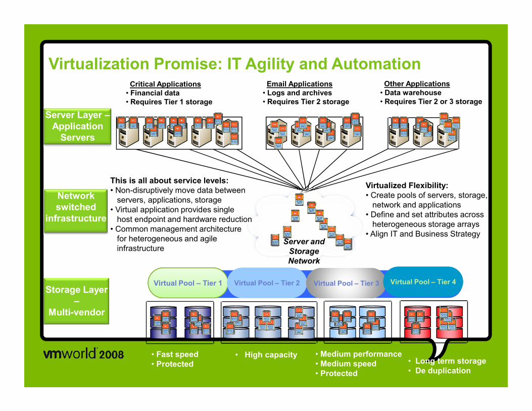
FCoE integrates FC into Ethernet
Ethernet
Network
Network
DriverFC
Driver
Server connects to storage using FC
FCoE FC Network
Ethernet
Ethernet
FC
Converged
Network Adapter
Standard 10G
CNA (DCE)
EMC SAN
iSCSI
EMC NAS
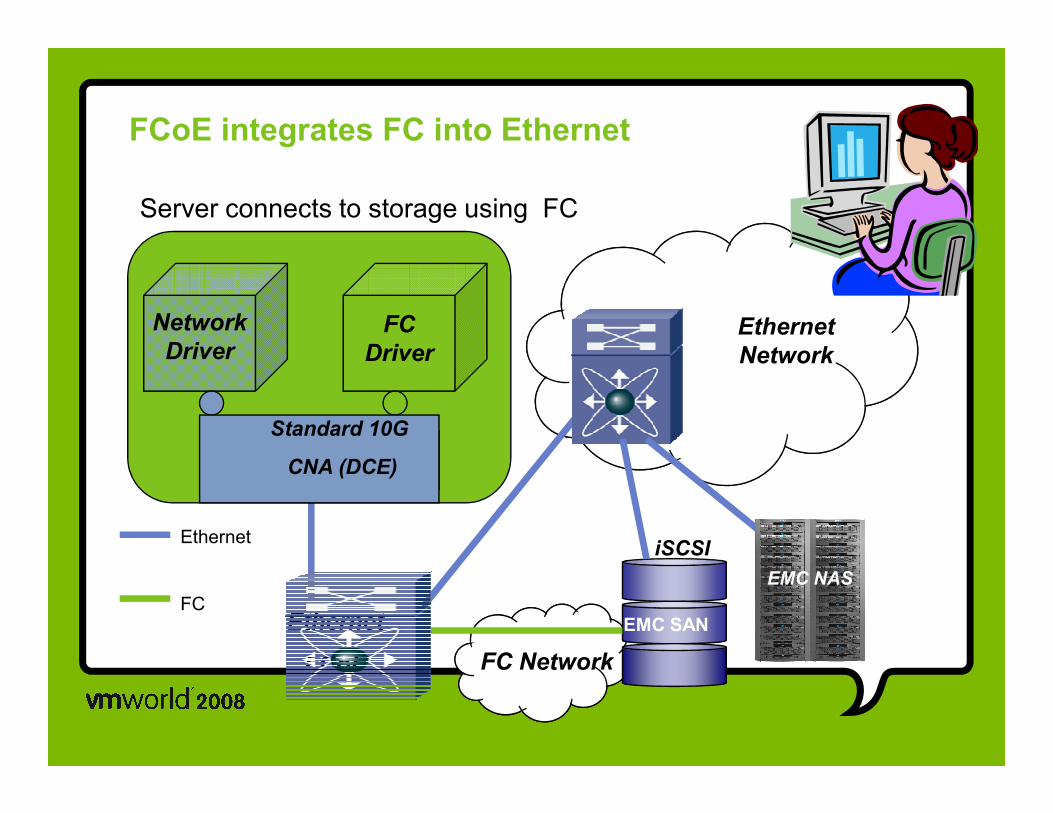
FCoE: Deployment
SAN A SAN B
10GE
Backbone
10Gbps Data Center
Ethernet
4/8 Gbps FC
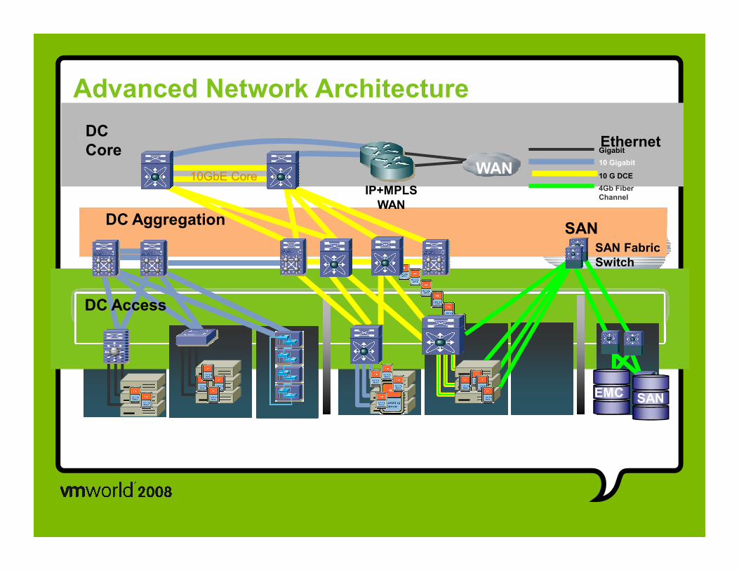
Advanced Network Architecture
DC
Core Gigabit
10 Gigabit
10 G DCE
4Gb Fiber
ChannelIP+MPLS
WAN
WAN
SANSAN Fabric
Switch
DC Aggregation
Ethernet
10GbE Core
DC Access
10GbE and 4Gb FC Server AccessBlade
EMC SAN
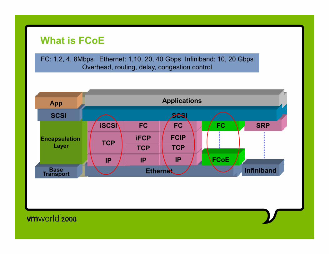
SCSI
App
iSCSI FC FC SRPFC
SCSI
Applications
What is FCoE
SCSI
App
iSCSI FC FC SRPFC
SCSI
Applications
FC: 1,2, 4, 8Mbps Ethernet: 1,10, 20, 40 Gbps Infiniband: 10, 20 Gbps
Overhead, routing, delay, congestion control
BaseTransport
Encapsulation
Layer
Ethernet
IP
TCP
iSCSI
IP
TCP
iFCP
FC
IP
TCP
FCIP
FC
Infiniband
SRP
FCoE
FC
BaseTransport
Encapsulation
Layer
Ethernet
IP
TCP
iSCSI
IP
TCP
iFCP
FC
IP
TCP
FCIP
FC
Infiniband
SRP
FCoE
FC

iSCSI
iSCSI and FCoE protocol comparison
FCSEthernetIP
TCP
iSCSI FC Data
FCoE
Ethernet FC 2112B FCS
FCoE is a FC frame encapsulated in LAN/ Ethernet
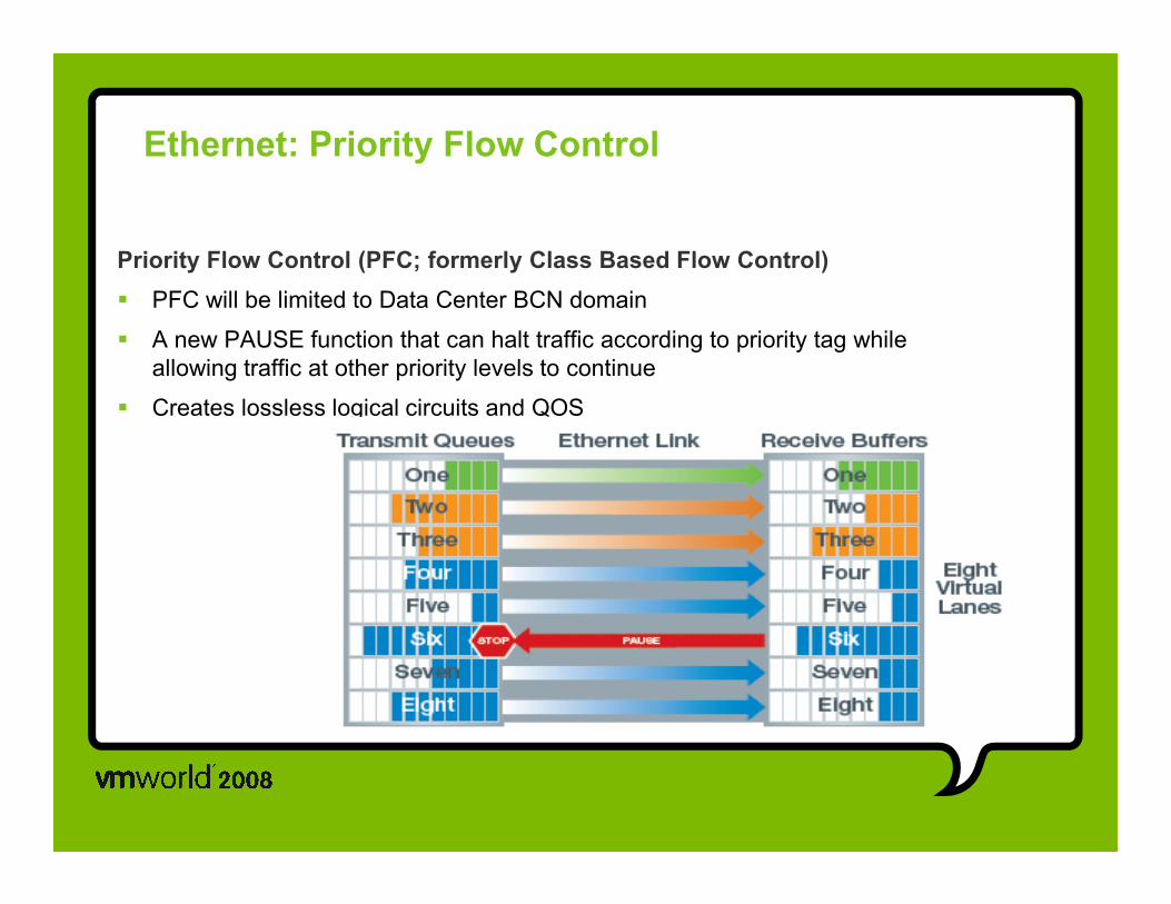
Ethernet: Priority Flow Control
Priority Flow Control (PFC; formerly Class Based Flow Control)
� PFC will be limited to Data Center BCN domain
� A new PAUSE function that can halt traffic according to priority tag while
allowing traffic at other priority levels to continue
� Creates lossless logical circuits and QOS
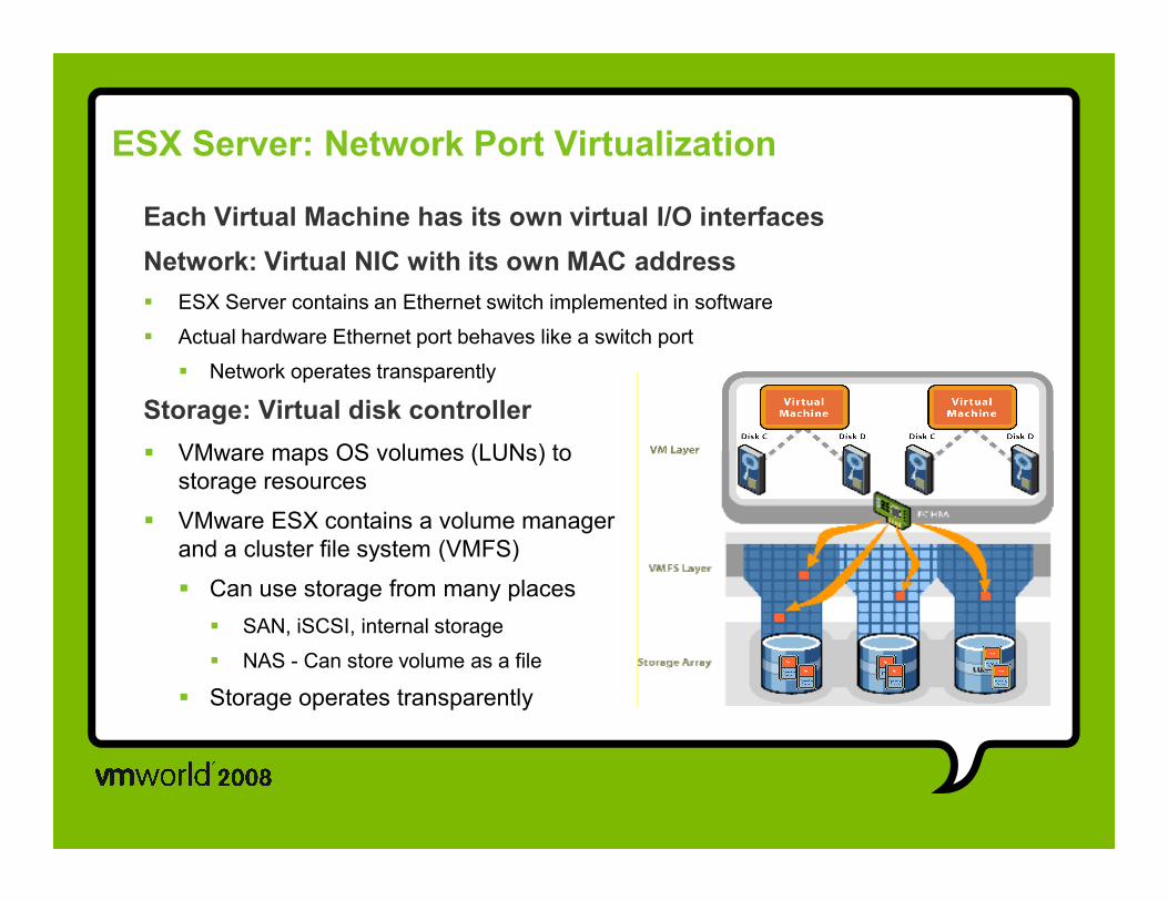
ESX Server: Network Port Virtualization
Each Virtual Machine has its own virtual I/O interfaces
Network: Virtual NIC with its own MAC address
� ESX Server contains an Ethernet switch implemented in software
� Actual hardware Ethernet port behaves like a switch port
� Network operates transparently
Storage: Virtual disk controller
� VMware maps OS volumes (LUNs) to� VMware maps OS volumes (LUNs) to
storage resources
� VMware ESX contains a volume manager
and a cluster file system (VMFS)
� Can use storage from many places
� SAN, iSCSI, internal storage
� NAS - Can store volume as a file
� Storage operates transparently

Computer Resources and Service Containers
E-CommerceWeb Tier
E-CommerceWeb Tier
App ServicesApp Services
Compute ServicesCompute Services
Storage ServicesStorage Services
Application Tier
Application Tier
Database Tier
Database Tier
ClusterClusterIntranet Web TierIntranet Web Tier
Network PlatformNetwork Platform
Pooled Compute Resources
PooledStorage
Resources
ServicesServices
Network ServicesNetwork Services
Content Caching
SSL Offloading
Firewall Services
Intrusion Detection
Server Balancing
Network Analysis
VPN Termination
File Caching
DOS Protection
Pooled App Resources
Pooled Network Service
Resources
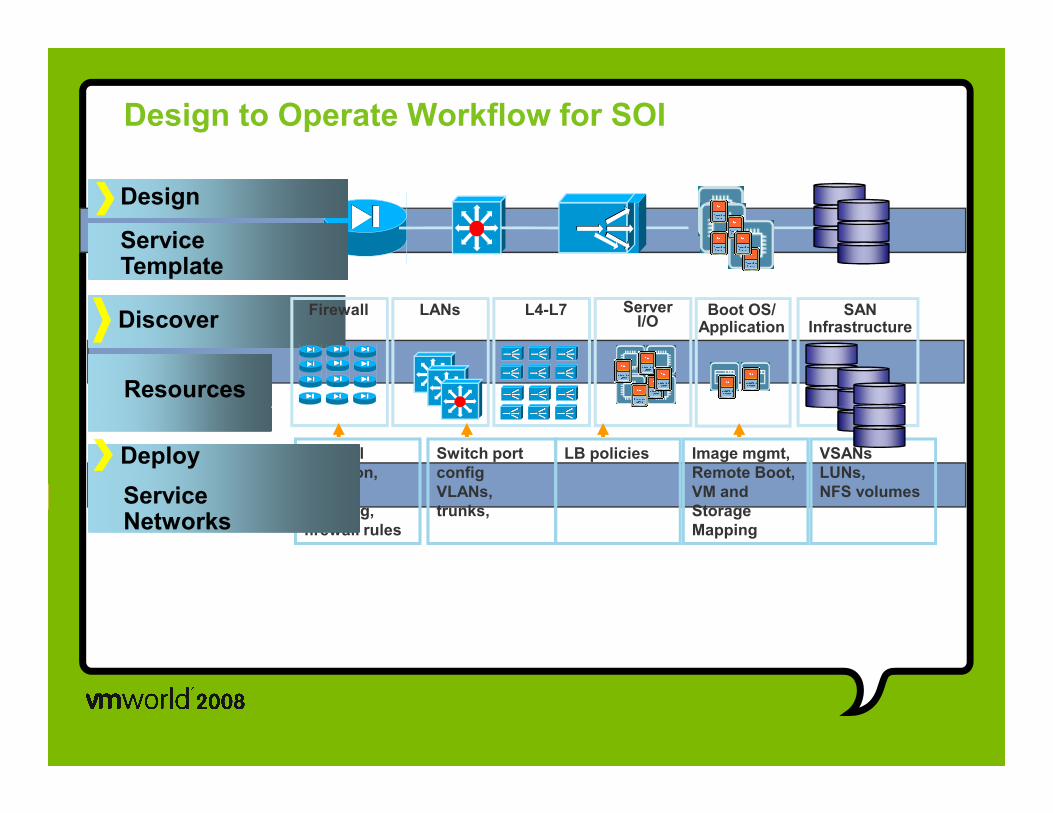
Design to Operate Workflow for SOI
Design
Service Template
Boot OS/Application
ServerI/O
SANInfrastructure
L4-L7LANsDiscover
Resources
Firewall
Switch port
config
VLANs,
trunks,
VSANs,
LUNs,
NFS volumes
Image mgmt,
Remote Boot,
VM and
Storage
Mapping
LB policiesFirewall
selection,
firewall
chaining,
firewall rules
Deploy
Service Networks
Slide 14
GC5 Good if in the "deploy" prt of the script for this slide, you define the following: DHCP, VIP, LB, LUN, NFSGeta Carlson, 7/6/2007
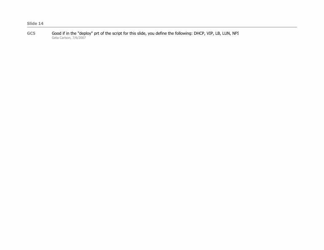
Examples: - physical server pool management- ability to add/remove servers in minutes
Physical Server Pools
DRS
• DRS optimizes the resource allocation through the use of resource pools within same cluster• Ability to add or remove server to or from a resource pool• To shift compute load and provide capacity from one ESX pool to another •
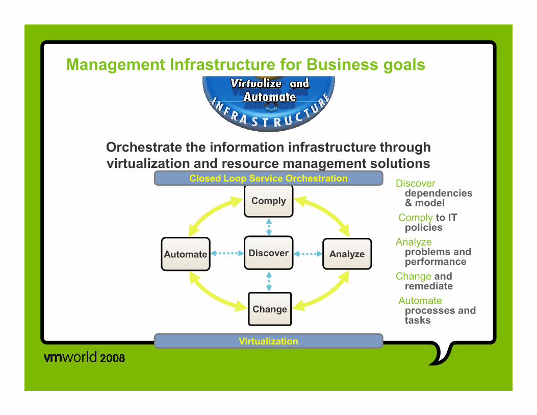
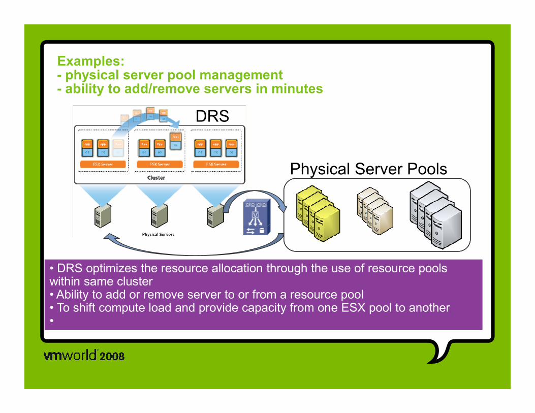
Management Infrastructure for Business goals
Orchestrate the information infrastructure through
virtualization and resource management solutions
Comply
Closed Loop Service Orchestration Discoverdependencies & model
Discover
Change
AnalyzeAutomate
Virtualization
& model
Comply to IT policies
Analyzeproblems and performance
Change and remediate
Automateprocesses and tasks
Ride the Wave