Embed Size (px)
DESCRIPTION
Electrical Protection
Citation preview

Optimizing Protection and Control Schemes Based on GOOSE Messages
Executive summary Historically, protection and control (P&C) schemes relied on hardwired connections between Intelligent Electronic Devices (IEDs). This approach makes correcting, modifying, and updating the P&C logic difficult. Using Ethernet in lieu of hardwiring and the IEC 61850 standard’s GOOSE messaging have simplified engineering changes. This paper discusses the pros and cons of two Ethernet protocols for GOOSE messaging — Parallel Redundancy Protocol (PRP) and High Availability Seamless Redundancy Protocol (HSR) — and strategies for using them in P&C schemes.
by Henri Grasset
998-2095-01-19-15AR
0

Optimizing Protection and Control Schemes Based on GOOSE Messages
Schneider Electric White Paper Revision 0 Page 2
Historically, protection and control (P&C) schemes have been based on the communication approach of using hardwired direct point-to-point connections between the Intelligent Electronic Devices (IEDs) with relay outputs wired to optically isolated inputs. This approach makes correcting, modifying, and updating the P&C logic difficult. However, the increasing use of Ethernet as the communication means of choice and the International Electrotechnical Commission (IEC) 61850 standard’s GOOSE (Generic Object-Oriented Substation Events) messaging have done away with such hardwiring and have simplified engineering changes greatly. While the Ethernet has its drawbacks — it is not easy for power engineers to configure, its remote access raises cybersecurity concerns, sent messages could get lost (though IEC 61850 GOOSE messaging precludes this possibility) — its only real weakness is network availability. If a link were lost, messages or packets of data could be lost or, in the case of GOOSE, information could avalanche or trip protection devices.
GOOSE replaces the traditional hardwired IEDs’ coordination with station bus communications. Upon detecting an event, the IEDs use a multi-cast transmission to notify those devices that have registered to receive the data. The performance requirements are stringent – no more than 3ms is allowed to elapse from the time an event occurs to the time the message is received in order, for example, to trip a breaker without any delay. IEC 61850 specifies two communication-redundancy protocols, which are defined in the IEC standard 62439-3: Parallel Redundancy Protocol (PRP) and High Availability Seamless Redundancy Protocol (HSR). Both rely on duplicating all transmitted data and enable zero-switchover time if links or switches fail.
Introduction
Figure 1 Example of communication traffic for station bus and process bus Source: IEC 61850-90-4_TR
Optimizing Protection and Control Schemes Based on GOOSE Messages
Schneider Electric White Paper Revision 0 Page 3
The common principle among all approaches to Ethernet redundancy is to enable the network to survive a single failure (i.e., N-1 redundancy) by providing alternate data path(s) when a link fault occurs. There are two basic redundancy techniques to ensure uninterrupted data communications: • Active redundancy, also known as hot-hot redundancy, or hot redundancy, where
both links are active at the same time (PRP and HSR)
• Passive redundancy, where one link is active and the other is in standby mode (RSTP) The passive redundancies are hot-standby, or warm, redundancy and cold redundancy (where the connection to the standby link/device is established only when communication with active one is lost)
Because it takes longer to reconfigure the network in the event of a network failure, passive redundancy technology is not suitable for high-availability environments (substations, metal refineries, chemical plants, and other electro-intensive users). Although the Rapid Spanning Tree Protocol (RSTP), standardized in 2004 by IEEE 802.1D, improves the original Spanning Tree Protocol (STP) by reducing reconfiguration time to hundreds of milliseconds, switchover time is still too slow for protection schemes because the electrical fault clearance time will be faster than the network reconfiguration time.
Issued in February 2010, IEC 62439-3 specifies two active redundancy protocols (PRP and HSR) that today’s IEDs have embedded to enable a higher-availability Ethernet network that allows: • Interoperability
• 0 ms reconfiguration time (no loss of data)
• Full compatibility with the IEC 61850 requirements
Until 2012–14, only proprietary solutions such as eRSTP, Self Healing Protocol (SHP), and Dual Homing Star (DHS) were available but they did not accommodate combining IEDs from different vendors, which made it challenging to develop solutions with different Main1 and Main2 IEDs that shared the same protection scheme.
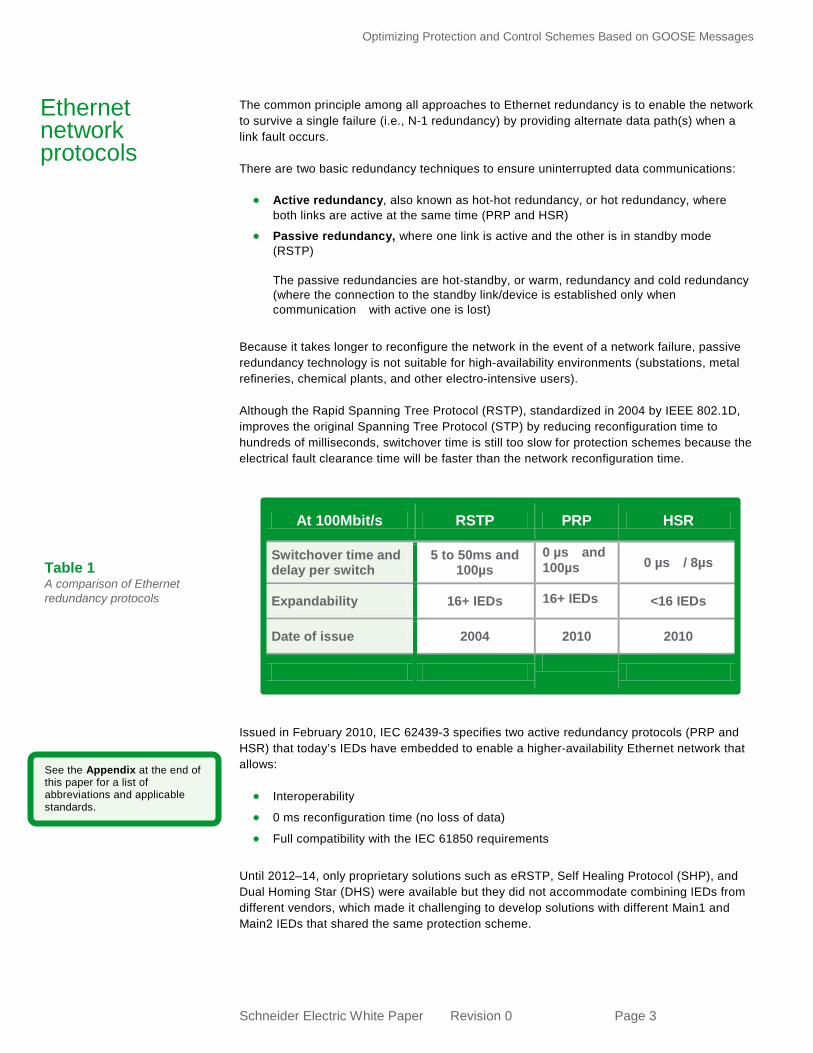
At 100Mbit/s RSTP PRP HSR
Switchover time and delay per switch
5 to 50ms and 100µs
0 µs and 100µs 0 µs / 8µs
Expandability 16+ IEDs 16+ IEDs <16 IEDs
Date of issue 2004 2010 2010
Ethernet network protocols
Table 1 A comparison of Ethernet redundancy protocols
See the Appendix at the end of this paper for a list of abbreviations and applicable standards.

Optimizing Protection and Control Schemes Based on GOOSE Messages
Schneider Electric White Paper Revision 0 Page 4
Both IEC 62439-3 protocols rely on duplicating all communication data via two Ethernet ports. Therefore, both are able to overcome the failure of a link or switch with zero-switchover time, thus fulfilling all the stringent real-time requirements of substation automation. The two protocols are: • The Parallel Redundancy Protocol (PRP) relies on the parallel operation of two local
area networks (LANs). PRP allows a mix of both redundant and non-redundant equipment on the same network (Figure 2).
• The High Availability Seamless Redundancy Protocol (HSR) applies the same principle
of parallel operation to a ring interconnecting IEDs with two ports links (Figure 3).
Comparison of redundancy protocols
Figure 2 PRP relies on the parallel operation of independent LANs in a double network infrastructure
Figure 3 HSR relies on ring topology, sending data not over two networks but in both directions of the single ring

Optimizing Protection and Control Schemes Based on GOOSE Messages
Schneider Electric White Paper Revision 0 Page 5
Parallel Redundancy Protocol (PRP) PRP was the first protocol to be implemented, and its interoperability was demonstrated during the UCAIug Network Redundancy Interoperability Demonstration at CIGRÉ Paris in August 2012 (Figure 4).
The principles of PRP comprise: • Two completely separated Ethernet networks (LANs) are operated in parallel.
• Each Doubly Attached Node with PRP (DANP) has an interface to each LAN.
• A DANP source sends a frame simultaneously on both LANs.
• A DANP destination receives both frames (in normal operation) and discards the duplicate.
• A singly attached destination receives only one frame.
• If a LAN fails, a DANP destination operates with the frames from the other LAN. PRP allows single and double network attachment devices (non-redundant and redundant devices) to be mixed on the same LAN, thus allowing laptops and workstations to be connected to the network with standard Ethernet adapters (non-redundant devices). See Figure 5.
Figure 4 The interoperability of PRP as demonstrated at CIGRÉ Paris in 2012
See the Appendix at the end of this paper for a list of abbreviations and applicable standards.

Optimizing Protection and Control Schemes Based on GOOSE Messages
Schneider Electric White Paper Revision 0 Page 6
Note: According to the IEC 8802-3 the Maximum Transmission Unit (MTU) — i.e. Ethernet maximum packet size — is 1518 bytes without VLAN and without PRP, 1522 bytes with VLAN and without PRP, 1524 bytes without VLAN and with PRP and 1528 bytes with VLAN and with PRP, and the MTU of Ethernet board of the Singly Attached Node (SAN) must be set to 1528 bytes. As PRP employs a double star topology, the communication bandwidth on each star made with a single link is not different than for a non redundant network. Consequently, this protocol can accommodate a greater number of IEDs than HSR can. PRP is “plug & play” — no special network engineering is required. It is possible to directly connect singly attached equipment such as a laptop or Human Machine Interface (HMI) to one of the two networks. However, additional switches are needed to build the double star network infrastructure, making the network cost of its deployment higher compared to HSR.
If for any reason an IED fails, only its protection function is lost. The other IEDs continue to communicate over the redundant LAN to protect and control electrical equipment. If for any reason a switch fails, the communication redundancy is lost but not the protection and control functions, as the messages sent on the healthy network are not disturbed. Recommendation: When the number of connected IEDs is large (more than16), a double star PRP is preferable in order to maximize the availability and communication performance.
Figure 5 PRP allows laptops and workstations to be connected to the LAN via standard Ethernet means
Figure 6 With PRP, an IED sends the same message on both networks

Optimizing Protection and Control Schemes Based on GOOSE Messages
Schneider Electric White Paper Revision 0 Page 7
High Availability Seamless Redundancy Protocol (HSR) HSR was the second protocol to be implemented, and its operability was demonstrated at the UCAIug Network Redundancy Interoperability Demonstration at CIGRÉ Paris in August 2014 (Figure 7).
The principles of HSR comprise: • One Ethernet network ring connects each Doubly Attached Node with HSR (DANH).
• A DANH source sends a frame simultaneously on both ports and blocks the sent messages if received.
• In normal operation all DANHs receive frames from both ring connections and instantaneously forward them.
• A DANH destination receives both frames in normal operation. It uses the first and discards the duplicate.
• If a link fails, a DANH destination operates with the frames from the other healthy path.
• A singly attached destination receives only one frame via the Redundant Box (RedBox) it is connected to.
HSR does not allow single and double network attachment devices (non-redundant and redundant devices) to be mixed on the same LAN. Consequently, laptops and workstations must be connected to the network via a dedicated redundancy device called a Redundant Box (RedBox). The HSR “cut through” technique allows latency around 8µs by hop and is therefore negligible. Because HSR forwards all messages from all IEDs, the communication bandwidth is proportional to the number of IEDs. Therefore, HSR is limited to about 16 communicating devices (at 100Mbit/s). As shown in Figure 8, each device needs to not only send its own messages but also pass all the messages coming from all the other IEDs. HSR is also “plug & play,” and because it employs single ring topology, additional switches are not needed.
Figure 7 The interoperability of HSR as demonstrated at CIGRÉ Paris in 2014
See the Appendix at the end of this paper for a list of abbreviations and applicable standards.

Optimizing Protection and Control Schemes Based on GOOSE Messages
Schneider Electric White Paper Revision 0 Page 8
If for any reason an IED fails, its protection function and the communication redundancy are lost, but the other IEDs continue to communicate, protect, and control the electrical equipment through a single communication network. Recommendation: When the number of connected IEDs is small (less than16), HSR is preferable in order to maximize the availability and communication performance. There are two types of protection and control (P&C) schemes: • IEDs that share the same overall application
• IEDs that are grouped together by sub-application (such as by feeder or by bay)
For example, when testing, performing maintenance on, or upgrading a bay, that bay would need to be isolated in order to prevent any GOOSE message from accidentally causing a trip on a healthy bay. It could be argued that segregating the LAN with Virtual Local Area Networks (VLANs) and Media Access Control (MAC) address filtering can be engineered by software in the switches (whether external or embedded in the IEDs) as well as in each IED. However, this approach depends on flawless engineering and bug-free equipment. Experience has shown that even in highly secured and robust substation systems, when things go wrong, the impact can be tremendous — with malfunctions leading to widespread blackouts. Strategy for combining protocols for protection network A safer approach than a virtual solution is to use a mix of both redundant protocols: single ring HSR for the IEDs sharing the same application, and a double star PRP to connect the overall large number of IEDs. Since both protocols are plug & play, no special engineering is necessary. Singly attached equipment such as a laptop or HMI would be connected to the PRP network. The idea is to gather the HSR rings with a PRP network optimized by two H-type RedBoxes per interconnection (Figure 9).
Figure 8 Each HSR device needs to not only send its own messages but also pass all the messages coming from all the other IEDs
Protection and control strategies

Optimizing Protection and Control Schemes Based on GOOSE Messages
Schneider Electric White Paper Revision 0 Page 9
These HSR rings created by sub-application (per feeder or bay, for example, as the number of IEDs is usually small) allow easy physical disconnections to the PRP network whenever needed. This mirrors the same communication principle as today’s relay to optically isolated inputs but with the advantage of an additional technological safeguard. When the two PRP fibres (or communication cables) from the RedBoxes are disconnected, all communications from that bay to the other ones stop. If the fibres (or cables) remain disconnected, the other IEDs or HMI will trigger an alarm for that situation — which is not the case if a wire from a relay to an optically isolated input has not been reconnected. As the two connections are open, no GOOSE will interfere with any of the other bays. For example, a GOOSE in test mode is not processed the same way by an IEC 61850 Ed.1 and IEC 61850 Ed.2 IED — thus, an Ed.1 GOOSE could cause an Ed.2 IED to trip. Further, if equipment jams and overflows the network, the problem is limited to this single bay ring as normally filtered by the RedBoxes. Even if this is not the case, a simple remedy is to disconnect the two connections. Strategy for connecting physically segregated P&C networks As PRP uses “classical” store-and-forward switching techniques, its latency is around 100µs at 100Mbit/s. In an HSR ring, the “cut through” technique allows latency around 8µs per hop (IED/RedBox), which gives 160µs for 20 IEDs — a negligible amount compared to the 4 to 10ms requirement for P&C scheme. Moreover, when the Precision Time Protocol (PTP) is used, as each hop can add a 50ns inaccuracy on top of the 200ns inaccuracy of the GPS receiver, the maximum number of hops is 16 (one way). But whatever the protocol or topology is, there are three major threats to P&C reliability: • The standard Multimedia Messaging Service (MMS) traffic (disturbance records, setting
files, etc.) using long frames (see Technical Report IEC 61850-90-4_TR) could delay GOOSE messages.
Figure 9 Recommended protection scheme gathers HSR rings for IEDs within PRP double star and 2 RedBoxes per connection

Optimizing Protection and Control Schemes Based on GOOSE Messages
Schneider Electric White Paper Revision 0 Page 10
• The classical avalanche of GOOSE messages on primary fault inception — i.e., when the P&C scheme reacts quickly — could overflow a network where other messages already flow. Technical Report IEC 61850-90-4_TR states that “one GOOSE application in an IED generates about 1 kbit/s in steady-state and about 10 kbit/s in burst conditions (when substation event occurs).”
• An IED malfunctions and overflows the connected network with GOOSE messages or other traffic.
Another important point is that for control, redundancy is not compulsory because its unavailability time constraint is much smaller than for protection. As previously pointed out, virtual LANs and MAC address filtering could accomplish the needed segregation of networks, but such an approach relies on complex engineering work. Alternatively, adding switches is an option, but doing so reduces the Mean Time Between Failures (MTBF) of the network used by the P&C scheme. A better solution duplicates the network where protection and control are mixed. This approach uses IEDs with dual IP features to connect the two physically segregated networks. Figure 10 shows a typical scheme where communication to the backup P&C system is over only a standard single communication network, and communication to the main P&C system over either a standard single communication network, or HSR (which is recommended) or PRP (which costs more).
But this scheme does not address the three major threats. A better solution separates the control (and engineering) network from the protection network, as shown in Figure 11.
Figure 10 Basic scheme where primary and backup P&C communication is over two networks
See the Appendix at the end of this paper for a list of abbreviations and applicable standards.

Optimizing Protection and Control Schemes Based on GOOSE Messages
Schneider Electric White Paper Revision 0 Page 11
In this scheme, communication to the control system is over a standard single communication network, and the protection scheme to the local IEDs uses the HSR protocol in order to avoid additional switching and to increase the communication availability. (A single network could be used but is not recommended, and the PRP protocol is also possible but costs more.) This does address the three major threats: • The standard MMS traffic (disturbance records, setting files, etc.) using long frames
cannot delay protection GOOSE messages because they flow in the other segregated network.
• The classical avalanche of GOOSE messages has the maximum bandwidth of this dedicated network.
• If an IED malfunctions and overflows the connected protection network with GOOSE messages or other traffic, the control network will not be lost.
Special dedicated requirements coming from usual practices Maintenance teams may have their own dedicated communication network (in Spain, for example), or there may be one specific communication network for Digital Fault Recording System (DFRS), as in Brazil.
Figure 11 Better scheme where communication for control is over standard single network, but protection uses HSR (for example)
Figure 12 Scheme where maintenance or DFRS is over standard single network, but P&C uses HSR (for example

Optimizing Protection and Control Schemes Based on GOOSE Messages
Schneider Electric White Paper Revision 0 Page 12
Communication to the maintenance system or to the DFRS can be over only a standard single communication network, and the communication to main P&C system can be over either a standard single communication network or HSR (which is recommended) or PRP (which costs more). Historically, protection and control (P&C) schemes were hardwired direct point-to-point connections between the various Intelligent Electronic Devices (IEDs). This approach made correcting, modifying, or updating P&C logic difficult. With today’s P&C schemes increasingly complex, Ethernet has become the preferred communication medium for substation P&C schemes. Initially, only proprietary protocols were available for Ethernet communications. This made interoperability among devices from different vendors problematic. The publication of IEC 61850 created an international standard for substation automation communication among multivendor IEDs. A key component of IEC 61850 is the Generic Object-Oriented Substation Events (GOOSE) mechanism whereby high-speed messages are multicast over an Ethernet network. IEC 61850 performance requirements are stringent — no more than 3ms is allowed to elapse from the time an event occurs to the time a message is received for protection. Two Ethernet communication protocols are fully compatible with IEC 61850 requirements and particularly for GOOSE messaging: • Parallel Redundancy Protocol (PRP), which relies on the parallel operation of two local
area networks (LANs)
• High Availability Seamless Redundancy Protocol (HSR), which applies the same principle of parallel operation to a ring interconnecting IEDs with two ports links
There is no “one size fits all” or “best” solution for which one to use. The optimal approach depends primarily on the number of IEDs and the importance of the P&C scheme. • For a small (<16) number of IEDs, single-ring HSR is preferable.
• For a large (16+) number of IEDs where there is no need to segregate either the physical network or sub-applications, a PRP topology is preferable.
• When there is a need to segregate either the physical network or sub-applications, combining single-ring HSR and double-star PRP is preferred because it optimizes the station bus comprising the number of bays in the HSR ring network and the PRP network. The other advantage is that it is very similar to the hardwired communication that exists today and can be easily understood and used much more quickly by P&C engineers.
• One of the best solutions is to add one dedicated non-redundant network for control and engineering, as it is more robust and easier to use.
Conclusion
About the author Henri Grasset is an Automation Intelligent Device Expert at Schneider Energy Division. He holds an engineering degree from the Ecole Centrale de Nantes in France. He has worked in the Protection and Control domain since 1999.
Optimizing Protection and Control Schemes Based on GOOSE Messages
Schneider Electric White Paper Revision 0 Page 13
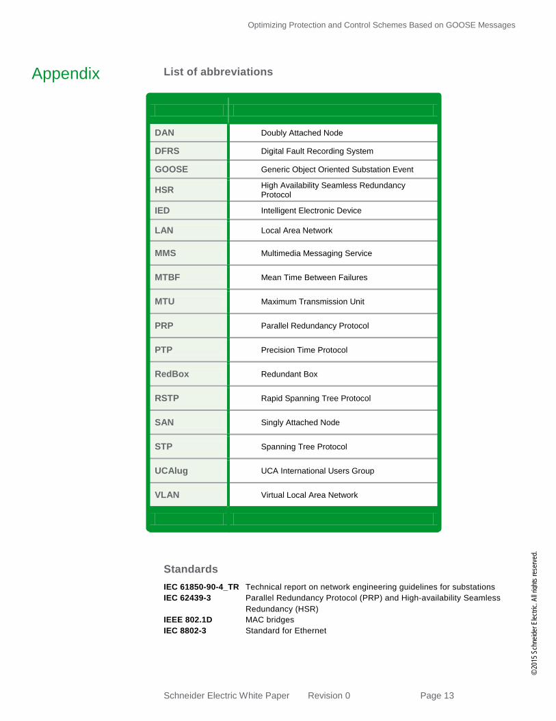
List of abbreviations
Standards IEC 61850-90-4_TR Technical report on network engineering guidelines for substations IEC 62439-3 Parallel Redundancy Protocol (PRP) and High-availability Seamless
Redundancy (HSR) IEEE 802.1D MAC bridges IEC 8802-3 Standard for Ethernet
DAN Doubly Attached Node
DFRS Digital Fault Recording System
GOOSE Generic Object Oriented Substation Event
HSR High Availability Seamless Redundancy Protocol
IED Intelligent Electronic Device
LAN Local Area Network
MMS Multimedia Messaging Service
MTBF Mean Time Between Failures
MTU Maximum Transmission Unit
PRP Parallel Redundancy Protocol
PTP Precision Time Protocol
RedBox Redundant Box
RSTP Rapid Spanning Tree Protocol
SAN Singly Attached Node
STP Spanning Tree Protocol
UCAlug UCA International Users Group
VLAN Virtual Local Area Network
©
2015
Sch
neide
r Elec
tric.
All ri
ghts
rese
rved.
Appendix