Embed Size (px)
Citation preview

3DS
.CO
M©
Das
saul
tSys
tèm
es| C
onfid
entia
l Inf
orm
atio
n | 4
/11/
2016
| ref
.: 3D
S_D
ocum
ent_
2014
Optimization techniques with
SIMULIA Tosca
Georgi CHAKMAKOV
SIMULIA Bulgaria

2
3DS
.CO
M/S
IMU
LIA
© D
assa
ultS
ystè
mes
| Con
fiden
tial I
nfor
mat
ion
| 4/1
1/20
16| r
ef.:
3DS
_Doc
umen
t_20
14
Optimization with SIMULIA Tosca
Introduction

3
3DS
.CO
M/S
IMU
LIA
© D
assa
ultS
ystè
mes
| Con
fiden
tial I
nfor
mat
ion
| 4/1
1/20
16| r
ef.:
3DS
_Doc
umen
t_20
14
A rough Classification into two Groups of Optimization
Methods
Both groups have their strengths → The feasible method depends on the given optimization task
Non-parametric
methods
Parametric
methods
Combination of
both groups
Sizing &
par. shape
DOE &
RSMRobustness
Reliability
Geometric
parameter
MDO
Structural
topology
Structural
shape
Bead
Fluid
topology
Isight
SIMULIA
Tosca Structure
SIMULIA
Tosca Fluid
Sizing

4
3DS
.CO
M/S
IMU
LIA
© D
assa
ultS
ystè
mes
| Con
fiden
tial I
nfor
mat
ion
| 4/1
1/20
16| r
ef.:
3DS
_Doc
umen
t_20
14
Parametric vs. non-parametric optimization
� Isight
�Size, shape and location of the cutout
is unknown and it is constrained by
parameters
� Tosca
�Size, shape and location of the cutout
is unknown, and thus, non-parametric
optimization
fixed
load

5
3DS
.CO
M/S
IMU
LIA
© D
assa
ultS
ystè
mes
| Con
fiden
tial I
nfor
mat
ion
| 4/1
1/20
16| r
ef.:
3DS
_Doc
umen
t_20
14
SIMULIA Tosca product line
� Find the design with maximum
stiffness or minimum weight
� Reduce local stresses and
increase durability
� Increase stiffness or
eigenfrequency of sheet
metal structures
Tosca Structure.topology Tosca Structure.shape
Images courtesy of AUDI AG Images courtesy of Ford Werke AG
Tosca Structure.bead Tosca Fluid.topology
Topology optimization of
channel flow to reduce
pressure drop
Best static and dynamic
behavior of sheet metal
components
Tosca Structure.sizing

6
3DS
.CO
M/S
IMU
LIA
© D
assa
ultS
ystè
mes
| Con
fiden
tial I
nfor
mat
ion
| 4/1
1/20
16| r
ef.:
3DS
_Doc
umen
t_20
14
Topology Optimization
SIMULIA Tosca Structure.topology

7
3DS
.CO
M/S
IMU
LIA
© D
assa
ultS
ystè
mes
| Con
fiden
tial I
nfor
mat
ion
| 4/1
1/20
16| r
ef.:
3DS
_Doc
umen
t_20
14 Change density of elements within design space considering:
Optimal material distribution for given optimization problem
Topology optimization approach
Design space
model
Optimization
max. stiffness
Relative
material
density
Design proposal
Objective functionMinimize/maximize quantity
ConstraintsPhysical bounds
DV constraintsManufacturing, symmetry
Process
Result
Low density
elements (voids)
Full density
elements (solids)
Intermediate
density
elements

8
3DS
.CO
M/S
IMU
LIA
© D
assa
ultS
ystè
mes
| Con
fiden
tial I
nfor
mat
ion
| 4/1
1/20
16| r
ef.:
3DS
_Doc
umen
t_20
14
Results transfer and generation of new CAD model� Export smoothed surface model in CAD-readable format (STL or IGS)
� Generate slices from smoothed results and export as IGS splines to be imported in CAD systems for
the generation of new CAD design
� Reduction of the facets possible
� Guidelines for efficient CAD reconstruction using CATIA native functionalities
Rough material
distributionSmoothing
STL or IGS
representation
IGS slicesInterpretation and
CAD reconstruction

9
3DS
.CO
M/S
IMU
LIA
© D
assa
ultS
ystè
mes
| Con
fiden
tial I
nfor
mat
ion
| 4/1
1/20
16| r
ef.:
3DS
_Doc
umen
t_20
14
Topology optimization of a transverse link at AUDI
Existing design
Design
space model
Topology optimization
Cutting splines
Redesign
Courtesy of AUDI AG

10
3DS
.CO
M/S
IMU
LIA
© D
assa
ultS
ystè
mes
| Con
fiden
tial I
nfor
mat
ion
| 4/1
1/20
16| r
ef.:
3DS
_Doc
umen
t_20
14 Existing design – new design
Comparison
� Speed-up of the development process
� 45% stress reduction, 10% weight reduction
� The 1st prototype passed all mechanical tests!
0
20
40
60
80
100
Weight Max. stress Max. displacement
Existing design New design
Admissible
Stress
(Image ATZ MTZ extra)
Result

11
3DS
.CO
M/S
IMU
LIA
© D
assa
ultS
ystè
mes
| Con
fiden
tial I
nfor
mat
ion
| 4/1
1/20
16| r
ef.:
3DS
_Doc
umen
t_20
14
Optimization and Additive Manufacturing� TOSCA is a powerful topology optimization tool for producing design concepts that often can’t be
manufactured using traditional techniques.
� Those designs are driven by the functional requirements of the part.
� Additive Manufacturing makes topology optimization results accessible for production.
Optimization for maximum stiffnessRestrictions on the
maximum bolt tension force
Restrictions on the
maximum allowed stress
Final weight 210g � 30% weight reduction
compared to an existing design
All stress and bolt
tension constraints
fulfilled

12
3DS
.CO
M/S
IMU
LIA
© D
assa
ultS
ystè
mes
| Con
fiden
tial I
nfor
mat
ion
| 4/1
1/20
16| r
ef.:
3DS
_Doc
umen
t_20
14
Shape Optimization
SIMULIA Tosca Structure.shape

13
3DS
.CO
M/S
IMU
LIA
© D
assa
ultS
ystè
mes
| Con
fiden
tial I
nfor
mat
ion
| 4/1
1/20
16| r
ef.:
3DS
_Doc
umen
t_20
14
SIMULIA Tosca Structure.shapeFunctionality
� Shape optimization by homogenization of the stresses
� Controller algorithm update rule:
� Node stress > reference value
→ Growth in order to reduce stress
� Node stress < reference value
→ Shrinkage in order to increase stress
� Result: homogeneous stress distribution to
the level of the reference value
� Very fast convergence
Homogeneous stress distribution results in a minimization of
the stress peaks in the design area but can also result in a
further mass reduction at a later product development stage. Growth Shrinkage s
σ
σref

14
3DS
.CO
M/S
IMU
LIA
© D
assa
ultS
ystè
mes
| Con
fiden
tial I
nfor
mat
ion
| 4/1
1/20
16| r
ef.:
3DS
_Doc
umen
t_20
14
SIMULIA Tosca Structure.shapeNon-parametric approach
� All optimization definitions directly on the FEA mesh
� Node group of surface nodes (design nodes)
� Node position can be modified
� Optimization displacement is calculated during optimization
� No shape basis vectors and/or morphing required
� Design variables are the displacement values of the design nodes
� Positive:
node “grows” out of the structure
� Negative:
node “shrinks” into the structure
Optimization
displacement direction
Design nodes
Displaced design nodes
Optimization
displacement
Courtesy of Daimler

15
3DS
.CO
M/S
IMU
LIA
© D
assa
ultS
ystè
mes
| Con
fiden
tial I
nfor
mat
ion
| 4/1
1/20
16| r
ef.:
3DS
_Doc
umen
t_20
14
Some Possible Objectives� Finite element solver result:
� Different stress criteria
� Nodal strain density
� Nodal plastic strains
� Different strain criteria
� Nodal contact pressure
� Maximizing the first natural frequency
� Fatigue results:
� Damage
� Safety Factor
Temp. [°C]
High
Low
Plasticity /
Fatigue
Max. contact pressure reduced
by 50 %
Pin mounted as
shrink fit
► Generally: stress or strain related responses

16
3DS
.CO
M/S
IMU
LIA
© D
assa
ultS
ystè
mes
| Con
fiden
tial I
nfor
mat
ion
| 4/1
1/20
16| r
ef.:
3DS
_Doc
umen
t_20
14 General shape optimization
New sensitivity based algorithm
� Free choice of design responses
(DRESP) in objective function
and constraint
� Optimize for stresses outside
the design area (DV)
� New implementation of
manufacturing constraint
� To be released
Design area
(∗∗∗∗NSET)
Stress hot spots
outside design areaStress hot spots
in design area
Load 1 Load 2
17
3DS
.CO
M/S
IMU
LIA
© D
assa
ultS
ystè
mes
| Con
fiden
tial I
nfor
mat
ion
| 4/1
1/20
16| r
ef.:
3DS
_Doc
umen
t_20
14
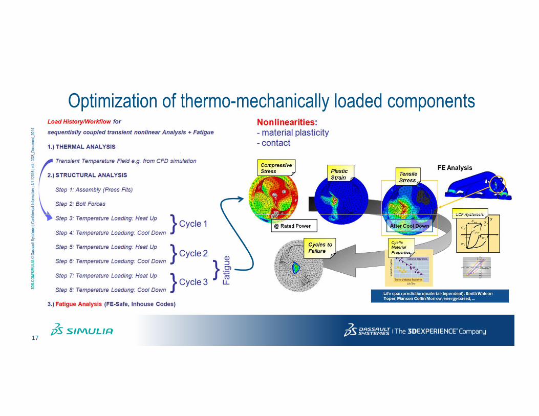
Optimization of thermo-mechanically loaded components

18
3DS
.CO
M/S
IMU
LIA
© D
assa
ultS
ystè
mes
| Con
fiden
tial I
nfor
mat
ion
| 4/1
1/20
16| r
ef.:
3DS
_Doc
umen
t_20
14
Shape optimization results of submodel
SF
Low
High
σendσ
Mean Stress
Am
plitu
de S
tres
s
σ
σa
UTSR p0.2
S = σa
Mean Stress
Am
plitu
de S
tres
s
σm
σ
UTSR
S =
σendσ
σendσ
Mean Stress
Am
plitu
de S
tres
s
σ
σa
UTSR p0.2
S = σa
Mean Stress
Am
plitu
de S
tres
s
σm
σ
UTSR
S =
σendσ
Shape optimization Optimized design
Safety factor increase: +40%; +10%; +43%

19
3DS
.CO
M/S
IMU
LIA
© D
assa
ultS
ystè
mes
| Con
fiden
tial I
nfor
mat
ion
| 4/1
1/20
16| r
ef.:
3DS
_Doc
umen
t_20
14 Optimization based directly on the equivalent plastic strain (PEEQ)
Optimization strategy for exhaust manifold
� Goal is fatigue life improvement, no target for weight reduction
0,61% 0,99% 1,43%
0,49%
0,54% 0,88% 1,14%
Initial design Optimized designSurface change
„Surface“
„Web 3 / 4“„Web 2 / 3“ „Web 1 / 2“

20
3DS
.CO
M/S
IMU
LIA
© D
assa
ultS
ystè
mes
| Con
fiden
tial I
nfor
mat
ion
| 4/1
1/20
16| r
ef.:
3DS
_Doc
umen
t_20
14
Optimization strategy 4 – Multilevel shape optimization
� Stage 1: User-defined parametric modification of the wall thickness in low-stressed areas for changing the stiffness and thermal expansion behavior with the morphing module of TOSCA
� Simultanous increase of the fatigue life in critical areas and weight reduction
� Stage 2: Standard shape optimization based on the result from Stage 1 for further increase of the fatigue life

21
3DS
.CO
M/S
IMU
LIA
© D
assa
ultS
ystè
mes
| Con
fiden
tial I
nfor
mat
ion
| 4/1
1/20
16| r
ef.:
3DS
_Doc
umen
t_20
14
SIMULIA Tosca Structure.morph: Manifold-ExampleAutomated generation of the best morphing combinations using Isight
Priorizing design/tracking
areas
Priorizing design/tracking
areas
calculation of surrogate models
calculation of surrogate models
performing an evolutionary
based optimization
performing an evolutionary
based optimization
evaluation of the best designs
evaluation of the best designs
22
3DS
.CO
M/S
IMU
LIA
© D
assa
ultS
ystè
mes
| Con
fiden
tial I
nfor
mat
ion
| 4/1
1/20
16| r
ef.:
3DS
_Doc
umen
t_20
14
Sizing Optimization
SIMULIA Tosca Structure.sizing

23
3DS
.CO
M/S
IMU
LIA
© D
assa
ultS
ystè
mes
| Con
fiden
tial I
nfor
mat
ion
| 4/1
1/20
16| r
ef.:
3DS
_Doc
umen
t_20
14
SIMULIA Tosca Structure.sizing
� Elemental thickness of shell elements as design variables
� Define lower and upper bounds on the thicknesses
� The thicknesses of the most typical shell element types are supported as design variables
� Shell element thicknesses can be
optimized
� clustered
� Combine shell thicknesses to combined design
variables via element and property groups
� individually
� The shell thickness of each element is a design
variable
� Handle several millions of design variables
Two optimization approachesThickness as design variables

24
3DS
.CO
M/S
IMU
LIA
© D
assa
ultS
ystè
mes
| Con
fiden
tial I
nfor
mat
ion
| 4/1
1/20
16| r
ef.:
3DS
_Doc
umen
t_20
14
Free thickness optimization of a car door
Group 1
Group 2
Group 3
Group 1
Group 2
Areas with
maximum
thickness
Areas with
minimum thickness
Evolution of the thickness distribution

25
3DS
.CO
M/S
IMU
LIA
© D
assa
ultS
ystè
mes
| Con
fiden
tial I
nfor
mat
ion
| 4/1
1/20
16| r
ef.:
3DS
_Doc
umen
t_20
14
Optimization resultsSecond clustered sizing run
Minimization of
the total volume
Convergence plots:
Normalized stiffness, eigenfrequencies and
total volume over the iterations
Absolute thickness
distribution
Evolution of the
thickness change
10% weight reduction while fulfilling all the stiffness and eigenfrequency constraints
26
3DS
.CO
M/S
IMU
LIA
© D
assa
ultS
ystè
mes
| Con
fiden
tial I
nfor
mat
ion
| 4/1
1/20
16| r
ef.:
3DS
_Doc
umen
t_20
14
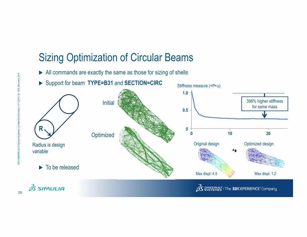
Sizing Optimization of Circular Beams
� All commands are exactly the same as those for sizing of shells
� Support for beam TYPE=B31 and SECTION=CIRC
� To be released
R
Radius is design
variable
Initial
Optimized
Stiffness measure (=P•u)
398% higher stiffness
for same mass
10 2000
0.5
1.0
Original design Optimized design
Max displ: 4.5 Max displ: 1.2

27
3DS
.CO
M/S
IMU
LIA
© D
assa
ultS
ystè
mes
| Con
fiden
tial I
nfor
mat
ion
| 4/1
1/20
16| r
ef.:
3DS
_Doc
umen
t_20
14
SIMULIA Tosca Structure.bead
Calculate an optimal bead layout to improve bending stiffness or vibration
behavior for sheet metal components

28
3DS
.CO
M/S
IMU
LIA
© D
assa
ultS
ystè
mes
| Con
fiden
tial I
nfor
mat
ion
| 4/1
1/20
16| r
ef.:
3DS
_Doc
umen
t_20
14
Optimization of beads using Tosca Structure.bead� Automatic determination of location and
orientation of beads for an increase of the moment of inertia
� Fast and stable optimization algorithms using special optimality criterion based on the bending stress
� Solution is independent from mesh
� Support of static or modal analysis
� Fast convergence using a controller based algorithm
� More soffisticated sensitivity based algorithm
� Good transfer and easy interpretation of results due to low scattering
Deflection without and with bead stiffener
Source: Oehler, „Steife Blech- und Kunstoffkonstruktion“

29
3DS
.CO
M/S
IMU
LIA
© D
assa
ultS
ystè
mes
| Con
fiden
tial I
nfor
mat
ion
| 4/1
1/20
16| r
ef.:
3DS
_Doc
umen
t_20
14
Preprocessing bead optimization� Static or modal analysis
� Shell or plate elements must be present
� All nodes at shell / plate elements may be used as design nodes
� The optimization displacement direction can be inverted using a SCALE parameter
Simply supported plate optimized with
respect to a static forceSimply supported plate optimized with
respect to 1st eigenfrequency

30
3DS
.CO
M/S
IMU
LIA
© D
assa
ultS
ystè
mes
| Con
fiden
tial I
nfor
mat
ion
| 4/1
1/20
16| r
ef.:
3DS
_Doc
umen
t_20
14 Tosca Structure Workflow

31
3DS
.CO
M/S
IMU
LIA
© D
assa
ultS
ystè
mes
| Con
fiden
tial I
nfor
mat
ion
| 4/1
1/20
16| r
ef.:
3DS
_Doc
umen
t_20
14
Integration of SIMULIA Tosca Structurein the existing CAE environment
CA
D s
yste
m
CA
D s
yste
m
CAE
preprocessingInteractive setup
CAE
postprocessing
Generation of CAE model
with group information
Fully automatic integration of non
parametric optimization
Evaluation of CAE
and optimization results
Abaqus/CAE
ANSA
Hypermesh
MEDINA
Patran
…
Abaqus/ViewermETAHypermeshMEDINAPatran…
Man
ufa
ctu
rin
g
Abaqus
MSC.Nastran
Ansys
SIMULIA Tosca Structure

32
3DS
.CO
M/S
IMU
LIA
© D
assa
ultS
ystè
mes
| Con
fiden
tial I
nfor
mat
ion
| 4/1
1/20
16| r
ef.:
3DS
_Doc
umen
t_20
14
Tosca Structure Optimization User Interfaces
Optimization Module
in Abaqus/CAE
Tosca ANSA environment (TAe)
Tosca Extension for
ANSYS Workbench
Tosca within ANSA Tosca Structure.gui

33
3DS
.CO
M/S
IMU
LIA
© D
assa
ultS
ystè
mes
| Con
fiden
tial I
nfor
mat
ion
| 4/1
1/20
16| r
ef.:
3DS
_Doc
umen
t_20
14
Fluid Optimization
SIMULIA Tosca Fluid

34
3DS
.CO
M/S
IMU
LIA
© D
assa
ultS
ystè
mes
| Con
fiden
tial I
nfor
mat
ion
| 4/1
1/20
16| r
ef.:
3DS
_Doc
umen
t_20
14 Sedimentation method
OC-based topology optimization
� The optimality criterion is to avoid flow recirculation
� An achieved consequence is (for many technical flows) a reduction of pressure
drop
� Redesign rule: elimination of local backflow and recirculation by “blocking out”
of backflow areas
� Provides an “optimization” approach by means of “improvement”
� Physics: Internal steady single-phase duct flow with low compressibility
35
3DS
.CO
M/S
IMU
LIA
© D
assa
ultS
ystè
mes
| Con
fiden
tial I
nfor
mat
ion
| 4/1
1/20
16| r
ef.:
3DS
_Doc
umen
t_20
14
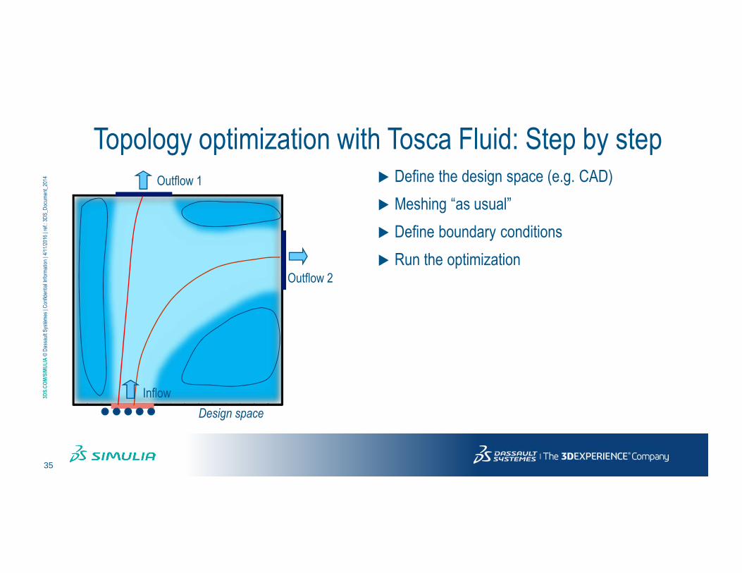
Topology optimization with Tosca Fluid: Step by step� Define the design space (e.g. CAD)
� Meshing “as usual”
� Define boundary conditions
� Run the optimization
Design space
Outflow 1
Outflow 2
Inflow

36
3DS
.CO
M/S
IMU
LIA
© D
assa
ultS
ystè
mes
| Con
fiden
tial I
nfor
mat
ion
| 4/1
1/20
16| r
ef.:
3DS
_Doc
umen
t_20
14
Topology optimization with Tosca Fluid: Step by step
Outflow 2
Optimized channel
shape
Prevented flow
Free flow
Transition area
(defining new channel shape)
Outflow 1
Inflow
Design space

37
3DS
.CO
M/S
IMU
LIA
© D
assa
ultS
ystè
mes
| Con
fiden
tial I
nfor
mat
ion
| 4/1
1/20
16| r
ef.:
3DS
_Doc
umen
t_20
14
Automotive HVAC flow splitter manifold
IN
OUT1
OUT2
Air, win = 5 m/s
Designspace
CFD model and design space Optimized designDimensions = 0,2 m x 0,14 m x 0,12 m
Boundary Conditions:
Inflow = INLET
Outflow = OUTLET
Fluid AIR
Isothermal
turbulent (Std k-e)
stationary
h = 1.81 · 10-5 kg/(m·s)
r = 1.205 kg/m3
Design Space
Optimized Design Proposal
38
3DS
.CO
M/S
IMU
LIA
© D
assa
ultS
ystè
mes
| Con
fiden
tial I
nfor
mat
ion
| 4/1
1/20
16| r
ef.:
3DS
_Doc
umen
t_20
14
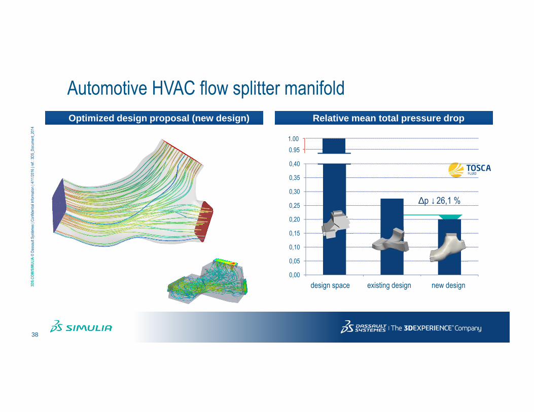
Automotive HVAC flow splitter manifold
∆p ↓26,1 %
Optimized design proposal (new design)
0,00
0,05
0,10
0,15
0,20
0,25
0,30
0,35
0,40
Std Opt
Relative mean total pressure drop
0.95
1.00
design space existing design new design

39
3DS
.CO
M/S
IMU
LIA
© D
assa
ultS
ystè
mes
| Con
fiden
tial I
nfor
mat
ion
| 4/1
1/20
16| r
ef.:
3DS
_Doc
umen
t_20
14
FEA Multiphysics
Simulation
Abaqus 6.14
Non-parametric Optimization
For Fluids and Structures
Tosca 8.1 & 2.4
Durability &
Fatigue
fe-safe 6.5
Process Integration &
Design Optimization
Isight 5.9
Improve Accuracy and Efficiency of Simulation Workflows
Leverage ALL through Extended Packaging licensing
Innovative Powerful Simulation Technology

40
3DS
.CO
M/S
IMU
LIA
© D
assa
ultS
ystè
mes
| Con
fiden
tial I
nfor
mat
ion
| 4/1
1/20
16| r
ef.:
3DS
_Doc
umen
t_20
14