Embed Size (px)
Citation preview
Journal of University of Babylon, Engineering Sciences, Vol.(26), No.(4): 2018.
283
Optimization of Power Consumption for the Design of 802.11n MIMO_OFDM System
Muthna Jasim Fadhil
Lecturer, Electrical Engineering Technical College, Middle Technical University
(MTU),Baghdad, Iraq
Abstract In modern systems communication, different methods have been improved to change the prior
imitative techniques that process communication data with high speed. It is necessary to improve
(OFDM) Orthogonal Frequency Division Multiplexing technique because the development in the
guideline communication of wireless system which include security data and transmission data
reliability. The applications communications of wireless is important to develop in order to optimize
the process of communication leads to reduce the level consumption energy of the output level signal.
The architecture of VLSI is used to optimize the performance transceiver in 802.11 n OFDM-MIMO
systems, this idea concentrate on the design of 6x6 MIMO_OFDM system in software simulink of
MATLAB then using generator system for transfer to code of VHDL and applying in FPGA Xilinx
Spartan 3 XC3S200 . The modelsim used to get the simulation while Xilinx power estimator is used to
calculate power. The results registered total power consumption about 94mW while compared with
previous work was 136mW which means a high reduction of about 30.8% .
Keywords: Simulink_MATLAB, Interference Inter carrier, FPGA ,QAM ,MIMO _ OFDM System.
1.Introduction:
The wireless channel of communication system has three main differences over
communication line of wire. First is scale_small and scale_large wilt,the second is the
obtrusion between receiver and transmitter coupling and the third is the movement of
user in network. The inherent of wilt, obtrusion and movement makes wireless
communication design challenge (Jiménez et.al.,2011). The design concentrate on the
dependability of the needs of connection to alleviate the effect of multipath and wilt.
In modern design of wireless concentrate on the gains efficiency of spectral for
medium of multipath by means of variety spatial using in MIMO system. The
capacity of the link growth linearly at the receiver and transmitter multiple antennas
for MIMO_OFDM system (Bansode et.al.,2014). Cancelation of interface, coding
brought to you by COREView metadata, citation and similar papers at core.ac.uk
provided by Journals of University of Babylon

Journal of University of Babylon, Engineering Sciences, Vol.(26), No.(4): 2018.
284
time space, forming beam and diversity spatial all these facility can be used to
optimize coverage and quality of the signal. Where the technology of MIMO system
use to increase performance of the system, such as efficiency spectral increased,
throughput user increased and better encasement. The technique transmission of
multicarrier is known as OFDM where a subcarrier rate lower is used to transmit over
a number of data stream.The transmission efficient spectrum technology is used for
OFDM digital communication of high speed rate. In other way for transmission
channel MIMO it is also suitable because capacity system enhancment and
interference inter-symbol interaction (Nooshab et.al., 2012 ). The data input
transmitted optimal allocated adaptively where between the side of receiver and
transmitter formed beams transmission orthogonal of the system. By combination
both technique of OFDM with MIMO system get requirements system desired such as
environment sight of line non in coverage good ,transmission reliable, efficiency
spectral is high and peak rate data also high (Zhou and Giank , 2005) . The designed is
analysis error point fixed with processor IFFT/FFT multiplier, Frequency(MHz)
,delay (ns) and Area (slices) all these represent standard parameters of FPGA.The
algorithm of Fast Hartley Transform (FHT) employs for this processor.Many FFT
algorithms grow for the last decades where the comparison of algorithms with each
other over the parameters of such as the number of operations mathematical,time
computation and requirements of memory.All the previous researches results proved
that FHT is the best algorithm using in FFT and applied in all platforms because the
time execution fastest and required small area of memory. In the designed of simulink
unit blocks system proposed where the arrangement block modified for the almost
unit of MIMO-OFDM and the function subsystem developed also[Nakutis,2013].
The process architecture MIMO is used to improve timing transmission,the designed
system MIMO_OFDM with simulink 802.11 architecture hardware which
implemented of software Xilinx and generator system. The designed system of
MIMO_OFDM 802.11 for model proposed presented in section3.The designed
system of MIMO_OFDM that power consumption reduced and complexity with work
related are represented in Section 4. Paper conclusions presented in section 7.
2. SDM MIMO_OFDM System:
SDM MIMO basic shows in fig.1 for system SR x ST ,let matrix channel denoted
by Z.The corresponding signal received and data multiplexed transmitted represent by
J= [J1, J2, …..,JST]T
and K=[K1,K2,…..,KSR]T ,it can be written as the received signal:
K=ZJ+ H …………….(1)
Where H=[H1, H2,….., HSR]T is white Gaussian noise where each Hi is a
process Gaussian independent with mean zero and variance ,where Z is MIMO
matrix channel described by:
Z=
(
)
…………………(2)
Where is the response channel from antenna transmit xth
to antenna receive
gth
(Trung et.al., 2014).

Journal of University of Babylon, Engineering Sciences, Vol.(26), No.(4): 2018.
285
Fig.1:Block Diagram Explain System of SDM MIMO.
For signals received detection used matrix weight receive as following:
=[ ,
= X K ………………………...(3)
For the kind of algorithm Fast Hartley Transform (FHT) matrix weight receive can be
represented by: XHY= ( ZZ Z)
-1 Z
Z ……………………..(4)
For the modulation OFDM the algorithm IFFT used to transform of symbols
complex of N group of each antenna to time domain represented by:
j(n)=
∑
…………………….(5)
While for the demodulation OFDM the algorithm of FFT used to convert
received signals in all antenna to frequency domain as module below:
J(y)=∑
…………………..(6)
Blocks processing design system(Van Perre et.al.,2015; Gangaram and Sankar ,
2014), Fig.2 shows baseband blocks processing receiver where subsection explained
layer physical WiMAX mobile consisting block each of functionality and foundation
algorithmic (FHT).The Matlab used to the modeled system included transmitter and
receiver channel beside that FPGA device utilize to implement the system which
constraints system real time in MIMO technology due to algorithms layer physical
nature intensive bit. Approach design register transfer level (RTL) and code VHDL
both are used to apply the algorithms based Matlab. The performance and precision
system are co simulated to implement VHDL and model Matlab.

Journal of University of Babylon, Engineering Sciences, Vol.(26), No.(4): 2018.
286
Fig.2: Architecture processing baseband and acquisition signal.
3. Methodology Design: The performance of existing system has more level consumption energy so the
system proposed concerned with decreasing the amount of consumption energy by
reducing the time transmission data also decrease the amount of consumption power
by reducing the value ratio of SNR. The level performance system being improved by
increasing the speed of process transmission data and reducing level complexity
circuit so the architecture 802.11 MIMO_OFDM used to improve transmission data
processing. The architecture software Xilinx is used to implement simulation VLSI
hardware , code VHDL conversion and software simulink design. The proposed
design contain from main 3 steps simulation Matlab,synthesis and design
implementation using VHDL / Verilog all these processes shown in fig.3.Simulink in
Matlab important must be before system and VHDL/Verilog design because it
provides the foundation to put the parameters required also easily mentioned errors in
model hardware. The design system in VHDL / Verilog have several bad thinks such
as time design long and simulation difficult so using these facilities applied in FPGA
important to cancel all the above worse thinks beside that using FPGA provide one of
most necessary parameters that increase processing of transmission data.

Journal of University of Babylon, Engineering Sciences, Vol.(26), No.(4): 2018.
287
Fig 3: Flow chart explain proposal system processing steps.
4. Proposed System Design 4.1.Transmitter Design:
Transmitter contains of a stream bit as an input,IFFT, mapping constellation,
converter serial to parallel and QAM modulator. Transmitter inputs represent by
stream bits data to avoid spectrum power signals inputs depending on data transmitted
actual so it tend to make sequence input scatter where the sequence bits randomized
through scrambler. Space time block coding (STBC) and multiplexing spatial (MS)
both methods used to process stream bits data in MIMO operation.Encoder
convolution can be used for bits data encoding while bits data twinging and mapping
using mapper.Wireless system diversity increases which interleaving through
transmission to conservation data from errors burst while plays insertion pilot is role
important to avoid inter carrier interference.Signals transform from time domain to
frequency domain by using IFFT blocks where the symbol OFDM subsequence of
independence and subcarriers orthogonality is protected using interval guard. The
proposed system of transmitter part shown in fig.4.
Descriptions
Simulation in
Matlab with FHT
algorithm
(VHDL /Verilog)
DESIGN CIRCUIT
CORRECT?
(ModelSim) ,
SIMULATION VHDL
SYNTHESIS FPGA
IMPLEMENTATION
CORRECT?
Embedded FPGA
YES
NO
NO
YES

Journal of University of Babylon, Engineering Sciences, Vol.(26), No.(4): 2018.
288
Fig.4: Transmitter details of system proposed designed.
4.2. Receiver Design: The receiver contains from stream bit output,demodulator, convertion from
parallel to serial and FFT processing.Coding signal in transmitter methods mentioned
how the blocks of receiver is design where the operation of receiver opposite exactly
than the transmitter. The receiver contains from 3 main parts unit detection MIMO,
FFT processing and synchronization.The eliminating of prefix cyclic symbol when
receiving then blocks of FFT convert signal to frequency domain from time domain
while an algorithm used to calculate FFT which is for transmitter evaluation.IFFT and
FFT are calculated using FHT algorithm while coding VHDL used in Navigator
Project Xilinx which is the designed receiver. The operation of subtraction, additions
and multiplication complex floating point used IP cores from receiver. The
demodulation process after operation of FFT which is used to look up table. Pleiad
received used to recover stream bits where receiver separate for tested and design for
4 and 8 points transmitter. ISE simulator used to simulation in synthesizes and
analysis timing in kit when code design is ready, fig.5 shows system proposed of
receiver part.

Journal of University of Babylon, Engineering Sciences, Vol.(26), No.(4): 2018.
289
Fig.5: Receiver details of system proposed designed.
5.Simulation and Implementation: The rate data is the number of bytes data over the time delay where 18 K byte is
the size of data usage for the major bits/symbol number transmitting over the total
time 0.837ns and rates data up to 1377.3 Mb/sec so for rate data high required QAM
order higher. Inter symbol interference (ISI) and noise affected strongly on the
scheme when increases bits/symbol number for the other side the model designed
MIMO_OFDM 6x6 required Test power, Schematic RTL,codes VHDL and Test
Bench to complete test of proposed system. The ISE Project Navigator used from
proposed model which required schematics RTL and codes VHDL where model
simulink check the system correctness using simulation test bench. The main model
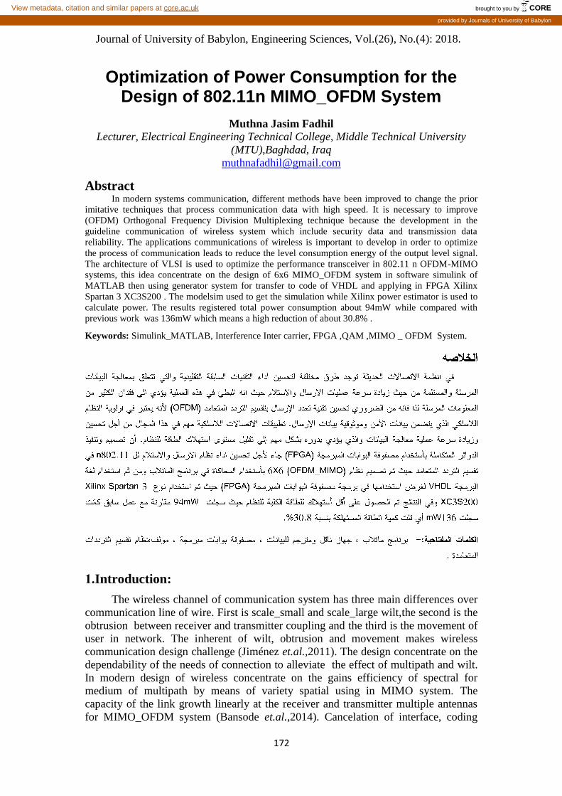
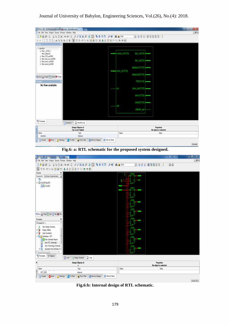
viewed the whole sub models of schematic RTL, fig.6 a,b represent RTL schematic
for the proposed system while fig.7 shows simulation waveform of 6x6
MIMO_OFDM in modelsim.
Journal of University of Babylon, Engineering Sciences, Vol.(26), No.(4): 2018.
28:
Fig.6: a: RTL schematic for the proposed system designed.
Fig.6:b: Internal design of RTL schematic.

Journal of University of Babylon, Engineering Sciences, Vol.(26), No.(4): 2018.
291
Fig.7: Simulation waveform for the proposed system.
The FPGA design summary results for 6x6 MIMO_OFDM system implemented
in FPGA Spartan 3 XC3S200 as shown in fig.8.
Fig.8:Design summary results of proposed system when implemented and synthesis in
FPGA Xilinx Spartan XC3S200.

Journal of University of Babylon, Engineering Sciences, Vol.(26), No.(4): 2018.
292
6. Power Determination: The design parameters which is used in implementation hardware like operation
frequency, delay time, consumption power and operation temperature are considerable
main parameters that should be take in consideration for chip design while for the
consumption power parameter important for the calculation the amount of power in
FPGA as the following:
Power consumption in FPGA= Quiescent power + Dynamic power
Dynamic power= FPGA power - Quiescent power
Dynamic power= 94-80=14mW
Fig.9: Power report in X-power Analyzer for the proposed system
The X-power analyzer tool is used for analysis power which already
programmed in FPGA Xilinx ISE 9.2i where the power report shown in fig.9
registered all the data parameters for the proposed system.
The readings of parameters design results registered with assistance of
Generator System Xilinx as in table_1.
Table_1: Comparison of design parameters results from the simulink for multi work.
Design parameter
work
previous [2]
work
proposed
Reduction %
a n n ( ) 28.6 25.3 11.5%
The number using of slices 233 94 59.6%
The number using of flip flop slice 246 91 63%
The number using of LUT's 4 input 162 88 45.6%
Using IOB number 463 93 79.9%
Maximum Period (ns) 5.7 0.837 85.3%
Maximum Frequency (MHz) 175.431 1193.773 85.3%
Rate Data Processing (Mbps) 835.7 1377.3
Total Power (mW) 136 94 30.8%
Quiescent Power Total (mW) 107 80 25.2%
Dynamic Power Total ( mW) 29 14 51.7%
Power summary : I(mA) P(mW)
Total estimated power consumption: 94
Signals: 0 0
Vcco25I 0 0
Outputs I: 0 0
Logic I: 0 0
Inputs I: 0 0
Clocks I: 0 0
Vcco25 2.30V: 0 0
Vccaux 2.40V: 64 302
Vccint 1.30V: 32 43
Quiescent power Vccaux 225V: 56 70
Dynamic power Vccaux 1.3V: 28 43
Journal of University of Babylon, Engineering Sciences, Vol.(26), No.(4): 2018.
293
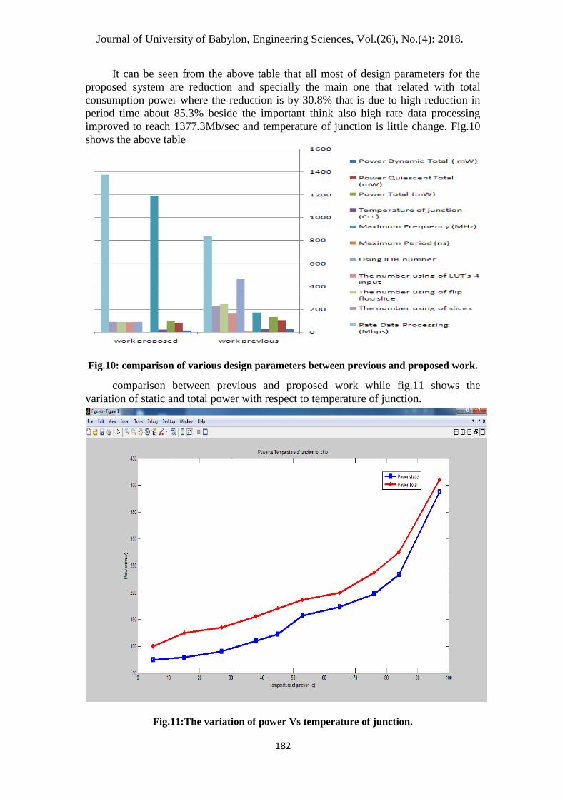
It can be seen from the above table that all most of design parameters for the
proposed system are reduction and specially the main one that related with total
consumption power where the reduction is by 30.8% that is due to high reduction in
period time about 85.3% beside the important think also high rate data processing
improved to reach 1377.3Mb/sec and temperature of junction is little change. Fig.10
shows the above table
Fig.10: comparison of various design parameters between previous and proposed work.
comparison between previous and proposed work while fig.11 shows the
variation of static and total power with respect to temperature of junction.
Fig.11:The variation of power Vs temperature of junction.

Journal of University of Babylon, Engineering Sciences, Vol.(26), No.(4): 2018.
294
The BER performance for hardware design are shown in fig.12 which explain
demodulation decision hard with FHT algorithm that comparison different decoding
decision( hard, soft and unquantized) decoding the figure explain that unquantized
decoding is better BER vs EbNo than the others decoding.
Fig 12: BER for the Demodulation Decision Hard with FHT algorithm
7. Results& Conclusions:
The transmitter and receiver of 6x6 MIMO_OFDM design and simulation using
MATLAB/ SIMULINK with FHT algorithm interfacing applied on FPGA Xilinx
Spartan 3 XC3S200 have VHDL circuit design get less BER results when splitting
MIMO_OFDM.The BER executing changeable depending on the received bits at the
receiver side beside that in this design system each behavior components hardware
simulate with assist of library that is provided from the tool modeling visual given by
the software of MATLAB/SIMULINK. The reduction cover most of design
parameters which includes the main one parameter consumption power which is
reduced by 23.5% and the chip area is reduced also compare with the previous system
while the rate data reaches the highest value registered about 1377.3 Mb/sec. beside
highly reduction in all the parameters of FPGA such as slices ,flip flop slices and
LUT's 4 input. The design and implementation proposed system on FPGA is
superlative than ASIC in terms of syncopation circuit size , area , cheap cost and high
speed processing data guide to high reduction in consumption power.

Journal of University of Babylon, Engineering Sciences, Vol.(26), No.(4): 2018.
295
Referances: Bansode K., Mishra J. and Temrikar H., 2014," Mapping level selective on FPGA
used for PAPR reduction of OFDM system in implementation hardware",
IOSR_JECE journal, ISNN:2278-2834, Volume 7,Issue 1.
Gangaram S. and Sankar J. Muthu , 2014,"Wireless Communication 4G interleaver
random used for MIMO-OFDM Novel design", IJRDET journal,Vol.2,Issue3.
Jiménez C., Garcya A. and Armada D., 2011,"Measurements channel testbed MIMO-
OFDM for WiMAX outdoor-indoor considerations system", EURASIP Journal
on networking and communication wireless, Vol.4,Issue5.
Nakutis J., 2013,"System embedded based FPGA for approach measurement
consumption current",IEEE Transaction for measurement and
Instrumentation,vol.65,no.6.
Nooshab S. , Iqbal M. ,Senior Member,IEEE and Lee Hueng,Member IEEE, 2012,
"MIMO_OFDM system communication for interleaving and coding design and
analysis", IEEE Electronics Consumer on transactions,vol.58, No.3.
Trung N.,Thanh N. and Ngoc A., 2014," Implementation and design SDM MIMO-
OFDM on FPGA for high speed networks wireless communication", IJRWS
journal ,volume2 ,Issue no.2.
Van Perre H., Palkovic D. and Cappele N., 2015," Platform SDR multi-processor for
processing baseband MIMO SDM-OFDM FOR 40 MHz mapping", Conference
IEEE for system circuit electronics diagnostic and design workshop, Bratislava.
Zhou K. and Giank R., 2005," Channels fading selective-frequency over transmission
coded-block time- space carrier",IEEE theory information transaction
vol.49,no.1.