Embed Size (px)
Citation preview

Procedia Engineering 86 ( 2014 ) 539 – 545
Available online at www.sciencedirect.com
1877-7058 © 2014 The Authors. Published by Elsevier Ltd. This is an open access article under the CC BY-NC-ND license (http://creativecommons.org/licenses/by-nc-nd/3.0/).Peer-review under responsibility of the Indira Gandhi Centre for Atomic Researchdoi: 10.1016/j.proeng.2014.11.078
ScienceDirect
1st International Conference on Structural Integrity, ICONS-2014
Optimization of Integrity Testing of Piping System in a Nuclear Fuel Cycle Facility
C.B. Rajeeva,*, M.V. Kuppusamya, G. Ramesha, M. Dhananjeyakumarb, B. Anandapadmanabana and B.Venkataramana
aQuality Assurance Division, Radiological Safety and Environmental Group, bReprocessing Group Indira Gandhi Centre for Atomic Research, Kalpakkam-603102, India
*E-mail ID: [email protected]
Abstract
Nuclear fuel cycle facility under construction at Kalpakkam houses more than 200 process vessels and equipments of different capacity and configurations and about 62 Kms of piping of varying sizes from 8 DN to 250 DN in about 5000 m3 of concrete cell volume. Austenitic stainless steel 304L has been widely used as work horse material for this plant due to its resistance to corrosion in acidic environment. The fabrication works of this facility involves more than 70000 weld joints for interconnecting various vessels, equipment and associated piping system. Pneumatic pressure testing and soap bubble leak testing are the two methods effectively used to assess the final integrity of the system after fabrication and erection. Physical verification of entire piping system as per the approved as-built drawing is a pre pneumatic test requirement. During physical verification, entire piping system will be physically scanned by visual inspection methods for orientation, gradient and also to identify any surface imperfections. Even though all surfaces of the piping system are examined before giving clearance for welding, the surfaces will be re-examined prior to integrity testing to ensure that piping system orientation is as per approved design and its surfaces are free from damages. Orientation and slope plays an important role in nuclear fuel cycle facility. Because nuclear fuel cycle facility is designed in such a way that gravitational force is effectively used to transfer process fluid to avoid the usage of moving mechanical parts. This is one of the zero maintenance design feature of nuclear fuel cycle facility. Based on experience many procedures are developed to ensure the intended design requirements. Before proceeding to the integrity testing, one has to verify the completion of all quality control stage inspection activities during fabrication by way of documents verification pertaining to the weld joints and loop involved in the testing. All inspection documents right from raw material identification, fabrication and inspection of components are to be verified prior to integrity testing. Verification of large number of inspection related documents posses a very big challenge. To meet this herculean task in time, an asset management system is designed and developed in house. Asset management system plays a key role in storage and retrieval of all inspection credentials and NDE images involved in the system, and with least amount of time these can be retrieved and verified. The asset management system also plays a constructive role during the pre commissioning activities of the plant. This paper emphasis the optimization methodologies adopted during integrity testing. © 2014 The Authors. Published by Elsevier Ltd. Peer-review under responsibility of the Indira Gandhi Centre for Atomic Research.
© 2014 The Authors. Published by Elsevier Ltd. This is an open access article under the CC BY-NC-ND license (http://creativecommons.org/licenses/by-nc-nd/3.0/).Peer-review under responsibility of the Indira Gandhi Centre for Atomic Research

540 C.B. Rajeev et al. / Procedia Engineering 86 ( 2014 ) 539 – 545
Keywords: Nuclear fuel cycle facility, Asset management system, integrity testing
Introduction
A nuclear facility under construction at Kalpakkam houses more than 200 process vessels and equipments of austenitic stainless steel 304L material and allied piping works of length around 62000 m with varying sizes from 8 DN to 250 DN with more than 70000 welds and over 140,000 radiographic exposures in about 5000 m3 of concrete cell volume. The major material joining process used in this facility is Gas Tungsten Arc Welding (GTAW) process. This nuclear facility is not amenable for maintenance during its operation due to high radioactive environment. This in turn makes the design, fabrication, and its erection of mechanical components a real challenging task. Also quality requirement of a plant of this kind is very much stringent compared with other conventional chemical plants. The base materials used for fabrication of vessels, equipments and piping systems are qualified by various destructive and non destructive testing methods before its fabrication. All weld joints are qualified by visual, liquid penetrant and radiographic examination or ultrasonic examination. The final integrity testing qualifies the totality of the system involving all vessels, equipments and
piping. This paper emphasis the optimization methodologies adopted during integrity testing.
Integrity Testing
Integrity testing ensures the final integrity of systems involving various types of vessels, equipments and piping. Pneumatic pressure testing method along with soap bubble leak testing method is used for checking the integrity of vessels, equipments and piping systems. Stagnation of water is intolerable in nuclear fuel cycle facilities. Hence pneumatic pressure testing method is used for final integrity test instead of hydrostatic testing method in fuel cycle facility. Soap bubble leak testing is effectively used to check the weld joint leakages. Integrity testing is conducted as per approved procedure.
Pneumatic Pressure Testing
Piping systems are classified as main loops and sub loops based on their service conditions. Test pressure for each system is also defined based on their design pressure. Pneumatic testing is performed as per ASME Sec.VIII div.I requirement. Oil free dry compressed air is used as a test medium in pneumatic pressure testing. All pressure gauges are calibrated as per IS 3624 class 1A requirements. Minimum two pressure gauges are used in pneumatic testing. Calibrated safety relief valves are also provided to protect the system from unexpected pressure rise. Pressure regulatory valves are also used during pressure rise of the systems. A loop sketch showing connections of all safety as well as mandatory gauges and instruments in the system are prepared for reviewing the system set up before pneumatic tests.
Figure 1 View of High Density piping inside the concrete cells

541 C.B. Rajeev et al. / Procedia Engineering 86 ( 2014 ) 539 – 545
Figure 2 Pneumatic test set up
Soap Bubble Leak Testing
In addition to pneumatic pressure testing, soap bubble leak testing is also used to check the weld joint leakages. Chloride contend in soap solution is controlled to a maximum of 25 ppm to protect the system from corrosion. D.M water is used for cleaning the system after soap bubble leak testing. Soap solution is applied by using brush. Mixing of concentrated soap oil with D.M.Water is done carefully to maintain the sensitivity level of the test.
Requirements Prior to Integrity Testing
Prior to integrity testing , all vessels, equipments and piping system involved in the test system is to be verified physically to ensure the design slope, orientation as per approved as built drawings. Orientation and slope plays an important role in nuclear fuel cycle facility. Because nuclear fuel cycle facility is designed in such a way that gravitational force is effectively used to transfer process fluid to avoid the usage of moving mechanical parts. This is one of the zero maintenance design feature of nuclear fuel cycle facility. During physical verification, total system is scanned for physical damages and arc strikes. In nuclear fuel cycle facilities, the minimum base material thickness is to be ensured to meet the design life of the plant in highly corrosive environment. Major portion of the stainless steel pipes used for the fabrication are having a thickness range of 2.24 mm to 2.27 mm. Hence, in a highly corrosive environment, a small reduction in thickness will leads to the premature failure of the material. Un intentional damage of the material due to reasons like arc strikes, grinding tool marks are to be avoided. In view of this a separate procedure is prepared to avoid arc strikes in base materials and thus to avoid base material damages.
Nuclear facilities are designed for a life of more than 20 years. The designed life of a plant can be assured only by implementing proper NDT methods during stage inspection. The effectiveness of the quality assurance practices is to be thoroughly reviewed to ensure the quality standard. An integrity test loop comprises of various equipments, vessels and piping systems fabricated by lot of weld joints. All base materials and weld joints are qualified by various NDT methods. All weld joints are undergone various stage inspection activities like visual, LPE, RT, UT, local passivation etc as per approved quality assurance plan during its fabrication. All quality control stage inspection activities generates its own inspection reports like weld inspection reports, NDT reports, surface treatment reports, erection and alignment reports, material identification certificates etc duly attested by inspection agencies. Prior to pneumatic testing, all quality assurance documents related to weld joints right from base material identification up to final integrity testing are to be thoroughly reviewed to ensure completion of stages inspection activities. Pneumatic test loop contains thousands of weld joints and each weld joints contains many stage inspection reports. Verification of large number of inspection related documents posses a very big challenge. Review of all these documents in time is really a herculean task. It requires lot of manpower and it consumes a large amount of time also. More over to maintain all documents for future reference large volume of space is also required. To
542 C.B. Rajeev et al. / Procedia Engineering 86 ( 2014 ) 539 – 545
achieve a paperless QA system, an efficient and effective method is required to meet the future challenges in mega projects. In order to meet the project schedule, it is necessary to optimize the integrity testing time by reducing the time required for document review. By keeping this in mind a novel information management system named as Asset & Knowledge Management System (AsKMe) is indigenously developed for a nuclear facility which is under construction at Kalpakkam.
Asset & Knowledge Management System (AsKMe)
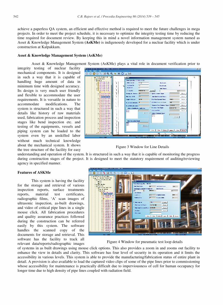
Asset & Knowledge Management System (AsKMe) plays a vital role in document verification prior to integrity testing of nuclear facility mechanical components. It is designed in such a way that it is capable of handling huge amount of data in minimum time with designed accuracy. Its design is very much user friendly and flexible to accommodate the user requirements. It is versatile in nature to accommodate modifications. The system is structured in such a way that details like history of raw materials used, fabrication process and inspection stages like bend inspection etc. and testing of the equipments, vessels and piping system can be loaded to the system even by an unskilled labor without much technical knowledge about the mechanical system. It shows the tree structure of the facility for easy understanding and operation of the system. It is structured in such a way that it is capable of monitoring the progress during construction stages of the project. It is designed to meet the statutory requirement of auditing/reviewing agency in specified manner.
Features of ASKMe
This system is having the facility for the storage and retrieval of various inspection reports, surface treatments reports, material test certificates, radiographic films, ‘A’ scan images of ultrasonic inspection, as-built drawings, and video of critical pipe lines in a single mouse click. All fabrication procedures and quality assurance practices followed during the construction can be referred easily by this system. The software handles the scanned copy of the documents for storage and retrieval. This software has the facility to track all relevant data/reports/radiographic images of systems in as built drawings using mouse click options. This also provides a zoom in and zooms out facility to enhance the view in details and clarity. This software has four level of security in its operation and it limits the accessibility in various levels. This system is able to provide the manufacturing/fabrication status of entire plant in detail. A provision is also available to load the captured video clips of some of the pipe lines prior to commissioning whose accessibility for maintenance is practically difficult due to imperviousness of cell for human occupancy for longer time due to high density of pipe lines coupled with radiation field.
Figure 3 Window for Line Details
Figure 4 Window for pneumatic test loop details

543 C.B. Rajeev et al. / Procedia Engineering 86 ( 2014 ) 539 – 545
Figure 5 Tank Details window
Figure 6 Features

544 C.B. Rajeev et al. / Procedia Engineering 86 ( 2014 ) 539 – 545
It will help to plan the strategy to carry out the repair on such line in the future by referring the video file. It documents the field problems as well as solutions and the tactics adapted to solve the problem, for the future reference to similar situations. The knowledge gained by the project personnel during the fabrication and erection of strategic projects are recorded as video clippings and stored for future reference. Pull down menus like file, view, and manage user, help etc are provided for the easiness in usage of this software. AsKMe is also having separate module named as Radiographic Information Management System (RIMS) to import the radiographs of field joints, carrying out digital image enhancement and signal processing to have increased probability of detection of defects
System Operation
The operation of this system is given as block diagram. It starts from the digitization of documents and NDE images and followed by the data entry in to the system, storage, retrieval, processing, interpretation and evaluation, review and monitoring of details. The entry of this documents/ images are done manually by scanning of documents including drawings, and digitization of RT films etc. Input method is made in such a way that ordinary man without much technical knowledge can also enter the data in to the system. Provision is made for updating/modifying the Data in a later stage. Provision for image processing is also made without affecting the original image. Processed images will be saved separately.Radiographic information management system (RIMS) can be integrated with AskMe.
Figure 7 System Operation
Data Storage and Security
High end server facility with raid feature is used to store the data. Server is provided with RAID facility to retrieve the data in the event of failure of some hard disks. This main server can be accessed by satellite computers through local area networking. It enables us to work in parallel. Multi layer security is provided for accessing the data. In each layer, the permission to access the data or the right to modify the data is limited. In one layer only viewing facility is available. Data cannot be edited. In another level we can access and edit the data. Such a way the security is also maintained.

545 C.B. Rajeev et al. / Procedia Engineering 86 ( 2014 ) 539 – 545
Conclusion
Asset & Knowledge Management System plays a vital role in optimization of integrity testing, by reducing the huge amount of time for QA document review. Such systems can be used for storage and retrieval of documents pertaining to various projects. NDE images also can be preserved for the future reference. Documents or NDE images can be stored and retrieved in a simple mouse click option. This attempt encourages to speed up the work of documentation which in turn helps to meet project schedule.


![GUIDELINE FOR THE MANAGEMENT OF UNDERGROUND PIPING … · NEI 09-14 [Rev 1] Nuclear Energy Institute Guideline for the Management of Underground Piping and Tank Integrity December](https://img.dokumen.tips/doc/110x75/5eda552cb3745412b5712a0d/guideline-for-the-management-of-underground-piping-nei-09-14-rev-1-nuclear-energy.jpg)


