Embed Size (px)
Citation preview

Research ArticleOptimization of Energy Recovery Efficiencyfor Parallel Hydraulic Hybrid Power Systems Basedon Dynamic Programming
Xiaobin Ning ,1 Jiarong Shangguan,1 Yong Xiao,2
Zhijun Fu ,1 Gaolun Xu,1 Anqing He,2 and Bin Li3
1College of Mechanical Engineering, Zhejiang University of Technology, Hangzhou, 310014, China2Zhejiang CRRC Electric Vehicle Co, Ltd, China3Department of Mechanical & Industrial Engineering, Concordia University, Montreal, H3G 1M8, QC, Canada
Correspondence should be addressed to Xiaobin Ning; [email protected]
Received 17 December 2017; Revised 6 December 2018; Accepted 21 January 2019; Published 27 February 2019
Academic Editor: Alberto Borboni
Copyright © 2019 Xiaobin Ning et al. This is an open access article distributed under the Creative Commons Attribution License,which permits unrestricted use, distribution, and reproduction in any medium, provided the original work is properly cited.
In this paper, an optimization algorithm of energy recovery efficiency is proposed for parallel hydraulic hybrid systems (PHHS)using dynamic programming (DP). Global optimal solution of pump displacement and transmission ratio under the known urbandrive cycles is obtained by using the DP approach, where the total amount of energy recovery is defined as the cost function, andthe pump displacement and the transmission ratio of the torque coupler are defined as the deciding variables. Two major steps areinvolved in verifying the proposed approach. Firstly, a PHHS Simulink model is accurately obtained by repeated comparison withthe bench test. Subsequently, we derive a parallel hydraulic hybrid vehicle (PHHV) from adding a hydraulic hybrid system to anelectric vehicle in ADVISOR (advanced vehicle simulator).This vehicle is used to validate the effectiveness of the proposed methodin energy recovery efficiency.
1. Introduction
It has been widely recognized that the fast developmentof hybrid vehicle (HV) presents a favorable solution toglobal warming and fossil fuel shortages. As compared toconventional cars with an internal combustion engine, a carwith hybrid power train has greater potential to improve effi-ciencies in fuel economy and reduce emissions from vehicles,since the brake-regenerated energy can be stored and reusedby extra power systems [1]. Hydraulic hybrid systems areextensively applied in the stop-and-go vehicles such as shuttlebus and refuse trucks [2, 3] for their advantages includinghigh power density, high energy conversion efficiency, andhigh rates of charging and discharging compared with thehybrid electric vehicles which use batteries to store energy.Studies have indicated that PHHS is the simplest way toimplement existing nonhybrid architectures as compared tothe series and power-split configurations, especially for thecommercial vehicles [4–6].
Optimal power management (OPM) design plays anessential role in improving hybrid power train efficiency.The current advanced optimal control methods have beendeveloped for OPM, such as those reliant on dynamic pro-gramming (DP) [7, 8], conventional model predictive control(MPC) [9], quadratic programming and genetic algorithm(GA) [10], and rule-based control [11], all focusing on an inte-grated methodology of propulsion and braking to improvethe fuel economy in a typical urban cycle. It is well knownthat the vehicles are frequently used to start and stop underthe driving condition of the city, and as much as 30%∼50%of kinetic energy is lost during the braking process [12]. Thisprovides a strong motivation to develop a more effectiveenergy recovery system for PHHS.Themajor factors affectingthe energy recovery efficiency of PHHS include drivingmode, running conditions, torque coupler transmission ratio,and the main hydraulic components parameters [13]. Plentyof scholars use hydraulic simulation software to build simula-tion model of PHHS in order to study the influencing factors
HindawiMathematical Problems in EngineeringVolume 2019, Article ID 9691507, 11 pageshttps://doi.org/10.1155/2019/9691507

2 Mathematical Problems in Engineering
[14, 15] for energy recovery efficiency of PHHS. Moreover,the optimization strategy for the parameters of the PHHS ismatched and analyzed in [16, 17]. Plenty of studies [18–22]have proved that dynamic programming offers an effectivemethod to improve fuel economy and reduce emissions fromhybrid vehicles by properly allocating power between theengine and the secondary power.
The global optimization of the hydraulic hybrid systemand the regenerative braking strategy of the vehicle are twoseparate parts. This paper place its focus on optimizing theparameters of the hydraulic hybrid system to enhance energyrecovery efficiency, regardless of the braking energy recoverycontrol strategy adopted in the electric or hybrid vehicle [23,24].The energy recovery efficiency can be improved, after thehydraulic hybrid system is improved based on the dynamicprogramming algorithm, which is also reflected in the fourthpart of the vehicle simulation.
In this paper, a DP-based optimization of energy recoveryefficiency algorithm is presented for PHHS. Global optimalsolution of pump displacement and transmission ratio underthe known urban drive cycles is obtained by DP method,where the aggregate amount of energy recovery is definedas the cost function, and the pump displacement and thetransmission ratio of the torque coupler are defined as thedecision variables. In order to improve the effectiveness ofthe vehicle simulation results, simulation tools are required toexhibit the advantages of reliability, robustness, and numeri-cal stability [25]. Therefore, we chose ADVISOR establishedin the Matlab/Simulink environment. Besides, we need todetermine the representative driving cycles, considering thevarious road conditions such as urban area and highway[26], for which we chose the 1015 and UDDS as the drivingcycles we used in this paper. Two major steps are included tovalidate the proposed approach as follows. Firstly, a PHHSMatlab/Simulink model is accurately obtained by repeatedcomparison with the PHHS bench test. Subsequently, weintegrated PHHS into the vehicle model of ADVISOR andgot a parallel hydraulic hybrid car. Through simulationverification, we demonstrated that our proposedDPHS basedon DP algorithm is effectively improving the efficiency ofbraking energy recovery.
The remainder of this paper is structured as follows. InSection 2, the PHHS model is presented. The proposed DP-based optimization of energy recovery efficiency algorithmis introduced in Section 3. Section 4 presents the benchtest experiment to verity the PHHS simulation model beforean analysis is performed on the simulation results of theproposed approach based on the whole vehicle model fromADVISOR. Finally, the conclusions are revealed in Section 5.
2. Parallel Hydraulic Hybrid Systems (PHHS)
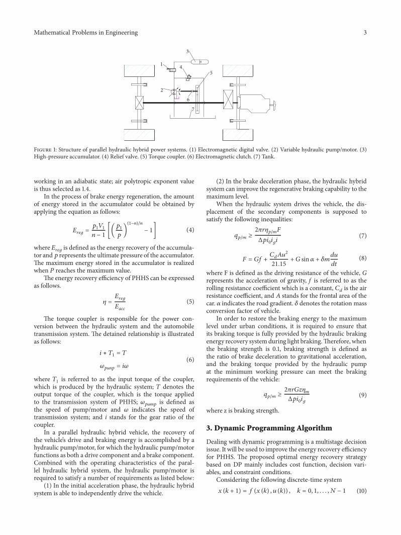
The general configuration of the PHHS is indicated inFigure 1, which consists of an electromagnetic digital valve,a variable hydraulic pump/motor, a high-pressure accumu-lator, a relief valve, a torque coupler, an electromagneticclutch, and a tank. The PHHS is connected by the torquecoupler with the drive system of the car, and the energy
recovery is achieved on the premise of maintaining theoriginal layout of the car chassis. In the entire system, thehydraulic pump/motor is used for the conversion betweenthe hydraulic potential energy and the kinetic energy of thecar. When the driver steps on the brake pedal, the controllercollects the brake signal, the electromagnetic clutch betweenthe energy recovery system and the vehicle power system isswitched off, and the PHHS starts to work. In the meantime,the hydraulic pump/motor is driven by the kinetic energy ofthe vehicle, and the energy is restored in the accumulator.Thebraking torque produced by the pump/motor can deceleratethe vehicle to a complete stop and the frictional brake wouldtake effect only at a timewhen the pump/motor is incapable toprovide sufficient braking force. When the vehicle starts, theelectromagnetic clutch is connected, and the PHHS works.Meanwhile, the energy stored in the accumulator is utilized todrive the hydraulic pump/motor. At this point, the secondaryelement operates as a hydraulic motor and provides torquefor start and acceleration of the vehicle.
Thekinetic energy of the vehicle before braking is selectedas the main objective of the energy recovery of the PHHS,which is simplified as
𝐸𝑎𝑐𝑐 = 0.5𝑚𝑢2 (1)
where 𝑚 represents the mass of the vehicle and u is definedas the velocity of the vehicle before braking.
The hydraulic pump/motor is the major component forconversion between the hydraulic potential energy of theaccumulator and the kinetic energy of the vehicle.The torqueprovided by the pump/motor is calculated as
𝑇𝑝/𝑚 = Δ𝑝𝑞𝑝/𝑚𝜂𝑝/𝑚𝑖0𝑖𝑔2𝜋 (2)
where 𝑇𝑝/𝑚 denotes the torque of the hydraulic pump/motorwhen the vehicle is in either the braking or driving conditions;Δ𝑝 is referred to as the working pressure of the hydraulicpump/motor; 𝜂𝑝/𝑚 is defined as the mechanical efficiencyof the hydraulic pump/motor; and 𝑞𝑝/𝑚 stands for thedisplacement of the hydraulic pump/motor. 𝑖0 is expressed asthe speed ratio of the transmission, and 𝑖𝑔 is the speed rationof the final drive.
Air bag accumulator is selected as the energy storageelement of PHHS. Based on the Boyle’s law, the relationshipbetween the volume and pressure of the hydraulic accumula-tor is described as
𝑝0𝑉𝑛0 = 𝑝1𝑉𝑛1 = 𝑝2𝑉𝑛2 = 𝑐𝑜𝑛𝑠𝑡 (3)
where𝑝0 is referred to as the initial pressure of the accumula-tor; 𝑝1 denotes the minimumworking pressure of the system;𝑝2 represents the maximum level of pressure in the system;𝑉0 is the volume of the accumulator gas corresponding to theinitial pressure; 𝑉1 is defined as volume of the accumulatorgas corresponding to the minimum working pressure; 𝑉2symbolizes the volume of the accumulator gas correspondentto the maximum pressure; 𝑛 is expressed as air polytropicexponent value. An assumption is made that the fluid in thehydraulic system is incompressible and the accumulator is
Mathematical Problems in Engineering 3
1
2
4
6
7
5
3
Figure 1: Structure of parallel hydraulic hybrid power systems. (1) Electromagnetic digital valve. (2) Variable hydraulic pump/motor. (3)High-pressure accumulator. (4) Relief valve. (5) Torque coupler. (6) Electromagnetic clutch. (7) Tank.
working in an adiabatic state; air polytropic exponent valueis thus selected as 1.4.
In the process of brake energy regeneration, the amountof energy stored in the accumulator could be obtained byapplying the equation as follows:
𝐸𝑟𝑒𝑔 = 𝑝1𝑉1𝑛 − 1 [(𝑝1𝑝 )(1−𝑛)/𝑛 − 1] (4)
where𝐸𝑟𝑒𝑔 is defined as the energy recovery of the accumula-tor and 𝑝 represents the ultimate pressure of the accumulator.The maximum energy stored in the accumulator is realizedwhen 𝑃 reaches the maximum value.
The energy recovery efficiency of PHHS can be expressedas follows.
𝜂 = 𝐸𝑟𝑒𝑔𝐸𝑎𝑐𝑐 (5)
The torque coupler is responsible for the power con-version between the hydraulic system and the automobiletransmission system. The detained relationship is illustratedas follows:
𝑖 ∗ 𝑇1 = 𝑇𝜔𝑝𝑢𝑛𝑝 = 𝑖𝜔 (6)
where 𝑇1 is referred to as the input torque of the coupler,which is produced by the hydraulic system; 𝑇 denotes theoutput torque of the coupler, which is the torque appliedto the transmission system of PHHS; 𝜔𝑝𝑢𝑚𝑝 is defined asthe speed of pump/motor and 𝜔 indicates the speed oftransmission system; and i stands for the gear ratio of thecoupler.
In a parallel hydraulic hybrid vehicle, the recovery ofthe vehicle’s drive and braking energy is accomplished by ahydraulic pump/motor, for which the hydraulic pump/motorfunctions as both a drive component and a brake component.Combined with the operating characteristics of the paral-lel hydraulic hybrid system, the hydraulic pump/motor isrequired to satisfy a number of requirements as listed below:(1) In the initial acceleration phase, the hydraulic hybridsystem is able to independently drive the vehicle.
(2) In the brake deceleration phase, the hydraulic hybridsystem can improve the regenerative braking capability to themaximum level.
When the hydraulic system drives the vehicle, the dis-placement of the secondary components is supposed tosatisfy the following inequalities:
𝑞𝑝/𝑚 ≥ 2𝜋𝑟𝜂𝑝/𝑚𝐹Δ𝑝𝑖0𝑖𝑔𝑖 (7)
𝐹 = 𝐺𝑓 + 𝐶𝑑𝐴𝑢221.15 + 𝐺 sin 𝛼 + 𝛿𝑚𝑑𝑢𝑑𝑡 (8)
where F is defined as the driving resistance of the vehicle, Grepresents the acceleration of gravity, f is referred to as therolling resistance coefficient which is a constant, 𝐶𝑑 is the airresistance coefficient, and 𝐴 stands for the frontal area of thecar. 𝛼 indicates the road gradient. 𝛿 denotes the rotation massconversion factor of vehicle.
In order to restore the braking energy to the maximumlevel under urban conditions, it is required to ensure thatits braking torque is fully provided by the hydraulic brakingenergy recovery systemduring light braking.Therefore, whenthe braking strength is 0.1, braking strength is defined asthe ratio of brake deceleration to gravitational acceleration,and the braking torque provided by the hydraulic pumpat the minimum working pressure can meet the brakingrequirements of the vehicle:
𝑞𝑝/𝑚 ≥ 2𝜋𝑟𝐺𝑧𝜂𝑚Δ𝑝𝑖0𝑖𝑔 (9)
where z is braking strength.
3. Dynamic Programming Algorithm
Dealing with dynamic programming is a multistage decisionissue. It will be used to improve the energy recovery efficiencyfor PHHS. The proposed optimal energy recovery strategybased on DP mainly includes cost function, decision vari-ables, and constraint conditions.
Considering the following discrete-time system𝑥 (𝑘 + 1) = 𝑓 (𝑥 (𝑘) , 𝑢 (𝑘)) , 𝑘 = 0, 1, . . . , 𝑁 − 1 (10)

4 Mathematical Problems in Engineering
where the state 𝑥(𝑘) represents an element of the space 𝑆𝑘,k=0, 1,. . ., N-1; 𝑢(𝑘) is input variable which belongs to thespace 𝐴𝑘, k=0, 1,. . ., N-1; and the control variable 𝑢(𝑘) issubjected to the constraint conditionswhich are reliant on thecurrent state 𝑥(𝑘) for all 𝑥(𝑘) ∈ 𝑆𝑘, k=0, 1,. . ., N-1, N.
The cost function is expressed as
𝐸 = 𝑁∑𝑘=0
𝐽𝑘 [𝑥 (𝑘) , 𝑢 (𝑘)] (11)
where 𝐽𝑘 indicates the cost function of each time step. Givenan initial state 𝑥(0), the problem lies in seeking a solutionset of 𝑢(𝑘) that minimizes the cost function. Here, the totalamount of energy recovery is selected as cost function. Incase that the drive cycle is determined, the vehicle speed ateach time is also determined. By dividing the total time into𝑁 segments with the time step Δ𝑡, then the energy recoveryis obtained as follows:
𝐸 = 𝑁∑0
𝑝 (𝑘) Δ𝑉Δ𝑉 = 𝑄 (𝑘) Δ𝑡 = 𝑞 (𝑘) ⋅ 𝜔 ⋅ 𝑖 (𝑘) ⋅ Δ𝑡
(12)
where 𝑝(𝑘) represents the pressure of accumulator at timek; Δ𝑉 is referred to as the volume change of gas, whichis equivalent to the volume change of oil; 𝑄(𝑘) is definedas the flow of hydraulic oil per unit time; 𝑞(𝑘) denotes thedisplacement of pump/motor at time k; 𝑖(𝑘) indicates the ratioof the torque coupler at time k.
The cost function at each step is described as follows.
𝐽𝑘 = 𝑝 (𝑘)𝑄 (𝑘) Δ𝑡 (13)
According to Boyle’s law, the pressure of the accumulatoris defined as follows.
𝑝 (𝑘) = 𝑝0𝑉1.40[𝑉 (𝑘 − 1) − 𝑄 (𝑘) Δ𝑡]1.4 (14)
Maximum energy recovery of PHHS is delivered bysatisfying the following conditions at each time step:
Δ𝑉 = max [𝑞 (𝑘) ⋅ 𝜔 ⋅ 𝑖 (𝑘) ⋅ Δ𝑡] (15)
where the displacement of the pump/motor 𝑞(𝑘) and theratio of the torque coupler 𝑖(𝑘) are selected as the decisionvariables.
The gas volume of accumulator is defined as a statevariable, such that
𝑉 (𝑘) = 𝑉 (𝑘 − 1) − 𝑄 (𝑘) Δ𝑡. (16)
Three constraint conditions are taken into considerationas follows:
(1) The braking torque of PHHS output is less than thetorque required by the vehicle.
(2) The speed of the hydraulic pump is no greater thanthe rated speed of the pump.
(3) The displacement of the hydraulic pump is no greaterthan the rated speed of the pump.
The method of torque evaluation provided by PHHS is
𝑇 (𝑘) = 𝑝 (𝑘) 𝑞 (𝑘) 𝑖 (𝑘) 𝑖𝑔2𝜋𝜂1 ≤ 𝑇𝑟𝑒𝑞 (𝑘) (17)
where the 𝑇(𝑘) is referred to as the output torque of PHHSat time k, 𝜂1 is defined as the efficiency of the hydraulicpump, and 𝑇𝑟𝑒𝑞(𝑘) indicates the braking torque required bythe vehicle at time k.
The displacement limitation on the hydraulic pump is
0 ≤ 𝑞 (𝑘) ≤ 𝑞𝑟𝑎𝑡𝑒𝑑 (18)
where 𝑞𝑟𝑎𝑡𝑒𝑑 represents the rated displacement of the pump.The restriction on rotating speed is
𝑤 (𝑘) = 𝑢 (𝑘)𝑟 𝑖0𝑖𝑔𝑖 (𝑘) ≤ 𝑤𝑟𝑎𝑡𝑒𝑑 (19)
where 𝑤(𝑘) indicates the rotating speed of the flywheel, 𝑢(𝑘)is referred to as the velocity of the vehicle, 𝑟 denotes the tireradius, and 𝑤𝑟𝑎𝑡𝑒𝑑 is expressed as the rated rotating speed ofthe pump.
According to the principle of Bellman, the decisionvariables under constraint conditions were selected in twourban drive cycles.The displacement of the selected hydraulicpump ranged from 0.02 to 0.05 L/r, with 20 different values.The value of the ratio is either 2.5 or 5. The flow chart of DP-based optimization of energy recovery efficiency algorithm isillustrated in Figure 2.
Vehicle speed in UDDS cycle and 1015 cycle are indicatedin Figure 3.
Subsequently, the optimal scheme for the displacement ofpump and ratio of the torque coupler in 1015 cycle and UDDScycle is derived in Figures 4 and 5, respectively.
4. Simulation and Experiment Results
In this section, two main steps are involved to validate theproposed approach. Firstly, a PHHSMatlab/Simulink modelis accurately obtained by repeated comparisonwith the benchtests.Then, the whole parallel hydraulic hybrid vehicle modelby integrating the PHHS Simulink model into the ADVISORis utilized for verification of the proposed approach.
4.1. Test Bench Experiments. Further with the mathematicalmodel of the major components for PHHS, a simulationmodel is established as shown in Figure 6. The simulationmodel is categorized into three separate subsystems, i.e.,flywheel, torque coupler, and hydraulic hybrid power system.The flywheel provides the power source of the system, whichis designed to drive the hydraulic system by the torquecoupler to store the energy in the accumulator. Meanwhile,the hydraulic system provides the brake torque for theflywheel.
The test bench for the PHHS is built up in the labas illustrated in Figure 7, which is intended to verify the

Mathematical Problems in Engineering 5
Initial setting
Y=1,2
Meet constraint conditions?
K=N?
K=K+1
OutputOptimalsolution
END
Invalid
No
No
Yes
Yes
Input $R∗CS
X=1,· · · ,20
*E=max(*∗E)
Figure 2: Flow chart of dynamic programming algorithm.
CYC_1015
100 200 300 400 500 600 7000time (sec)
0
20
40
60
80
spee
d (k
m/h
)
(a)
CYC_UDDS
200 400 600 800 1000 1200 14000time (sec)
0
50
100
spee
d (k
m/h
)
(b)
Figure 3: Duty cycles. (a) 1015. (b) UDDS.
simulation model.Themain parameters in relation to the testbench are listed in Table 1.
As displayed in Figure 7, the flywheel is driven bythe motor when the electromagnetic clutch is connected.Then the rotating flywheel is used to simulate the kineticenergy prior to the vehicle being braked. Where the flywheelreaches a certain speed, the electromagnetic clutch (2) isdisconnected, the electromagnetic clutch (7) is connected,and the hydraulic pump/motor is driven by the flywheel. Atthis moment, the hydraulic pump/motor works as a pumpto fill the accumulator with oil. The kinetic energy of theflywheel is converted into a hydraulic potential energy storedin the accumulator. When the energy is released by PHHS,
the dump valve is opened up, and the hydraulic potentialenergy in the hydraulic accumulator drives the pump/motor.At thismoment, themotor/pumpdrives the flywheel to rotatein the form of a motor, converting the hydraulic potentialenergy into kinetic energy. The magnetic powder brake isutilized to supplement the braking force when the brakingtorque provided by the hydraulic regenerative braking systemis insufficient. The wheel motor displayed in the Figure 7 ispurposed for conducting future research, for which it is notinvolved in this study.
Over the course of the simulation and the bench testexperiment, the initial pressure of the hydraulic accumulatoris set at 5MPa. According to the empirical formula, the

6 Mathematical Problems in Engineering
Disp
lacem
ent o
fTr
ansm
issio
n ra
tio o
f
100 200 300 400 500 600 7000Time (s)
100 200 300 400 500 600 7000Time (s)
010203040
pum
p (m
l/r)
012345
torq
ue co
upler
Figure 4: Optimal solution of the displacement of pump and ratio of the torque coupler from 1015 drive cycle.
Tran
smiss
ion
ratio
of
Disp
lacem
ent o
f
200 400 600 800 1000 1200 14000Time (s)
200 400 600 800 1000 1200 14000Time (s)
010203040
pum
p (m
l/r)
012345
torq
ue co
upler
Figure 5: Optimal solution of the displacement of pump and ratio of the torque coupler from UDDS drive cycle.
Table 1: Parameters of the test bench.Component Description Value/UnitPump/motor Maximum displacement 0.107L/r
Maximum speed 2400r/minRated pressure 31.5MPaTotal efficiency 98%
Accumulator Initial gas volume 25LMaximum pressure 31.5MPa
Flywheel Moment of inertia 45.3kg.m2Rated speed 1800r/min
minimum working pressure of hydraulic accumulator is5.6MPa, and the displacement of hydraulic pump is 0.05L/r.The initial speed of flywheel is chosen as 360 rpm, 300 rpm,and 300 rpm, which correspond to the friction brakingtorque provided by magnetic powder brake with 0Nm, 0Nm,and 40 Nm, respectively. The results from carrying out thesimulation and experiment with the flywheel speed as well asthe accumulator pressure have been shown in Figures 8 and 9,respectively (the dotted line represents the simulation result,and the solid line represents the experimental result). Asrevealed by Figure 8, the simulation and experimental results
of the flywheel speed are broadly consistent except for someinsignificant vibration in the experimental results. At thesame time, it is discovered from Figure 9 that the simulationand experimental results of the accumulator pressure arebasically unchanged except for the time delay at the initialstage. Due to the impact made by the hydraulic and mechan-ical components, the time delay of the bench experiment isabout 0.7s, and the error between the simulation and thebench experiment comes to approximately 10%. The greaterthe initial speed of the flywheel, the longer the duration ofthe whole process. As the initial speed of the flywheel is onthe rise, the final pressure of the hydraulic accumulator is alsoshowing an increasing trend. The energy recovery efficiencyin terms of each initial condition is calculated accordingto (12), which is already indicated in Table 2. When themechanical friction is involved, the ultimate pressure of thehydraulic accumulator is lowered, and the energy recoveryefficiency of the hydraulic regenerative braking is reduced asa result. Moreover, it is visible as in Figure 9 that the finalpressure of the hydraulic accumulator is slightly lower thanthat shown in the simulation results. This is attributed to theenergy loss from the mechanical components and hydraulicpipes in the test bench, which contributes to the ultimate

Mathematical Problems in Engineering 7
braking torque
Speed input
Hydraulic hybrid power system
Torque input
Speed input
Torque output
Torque coupler
Speed of flywheel
Flywheel
Figure 6: Simulation diagram of PHHS.
Figure 7: Test bench. (1) Asynchronous motor. (2) Electromagnetic clutch. (3) Magnetic powder brake. (4) Flywheel. (5) Speed sensor.(6) Mechanical commutator. (7) Electromagnetic clutch. (8) Pump/motor. (9) Tank. (10) Relief valve. (11) Hydraulic pressure sensor. (12)Accumulator. (13)Hub motor. (14) Current proportional amplifier. (15)Dump valve.
Flyw
heel
spee
d in
sim
ulat
ion
and
expe
rimen
t (rp
m)
0
100
200
300
400
5 10 15 20 25 300
Time (s)
360rpm300rpm300rpm+40Nm
300 rpm +40 Nm300 rpm360 rpm
Figure 8: Simulation and experimental results of flywheel speed.
Fina
l pre
ssur
e of a
ccum
ulat
orin
sim
ulat
ion
expe
rimen
t (Pa
)
00 5 10 15
Time (s)360rpm
360rpm300rpm 300rpm300rpm+40Nm
300rpm+40Nm
20 25 30
1
2
3
4
5
6
7
8 ×10⁶
Figure 9: Simulation and experimental results of accumulator pressure.
8 Mathematical Problems in Engineering
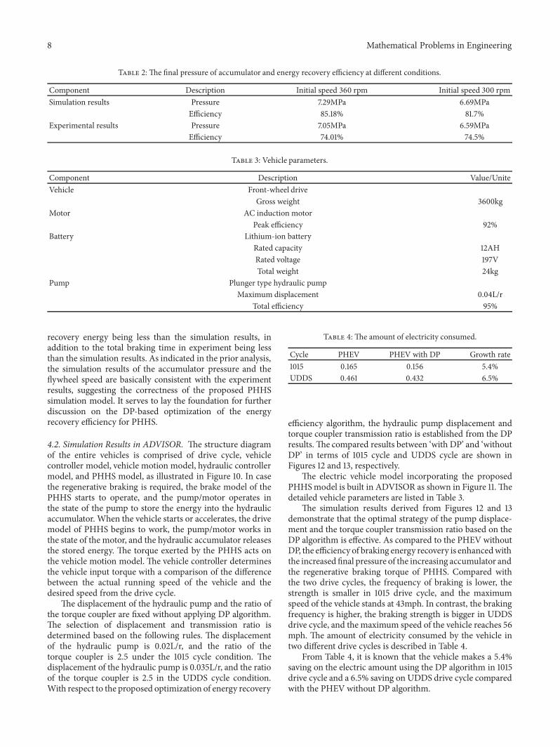
Table 2: The final pressure of accumulator and energy recovery efficiency at different conditions.
Component Description Initial speed 360 rpm Initial speed 300 rpmSimulation results Pressure 7.29MPa 6.69MPa
Efficiency 85.18% 81.7%Experimental results Pressure 7.05MPa 6.59MPa
Efficiency 74.01% 74.5%
Table 3: Vehicle parameters.
Component Description Value/UniteVehicle Front-wheel drive
Gross weight 3600kgMotor AC induction motor
Peak efficiency 92%Battery Lithium-ion battery
Rated capacity 12AHRated voltage 197VTotal weight 24kg
Pump Plunger type hydraulic pumpMaximum displacement 0.04L/r
Total efficiency 95%
recovery energy being less than the simulation results, inaddition to the total braking time in experiment being lessthan the simulation results. As indicated in the prior analysis,the simulation results of the accumulator pressure and theflywheel speed are basically consistent with the experimentresults, suggesting the correctness of the proposed PHHSsimulation model. It serves to lay the foundation for furtherdiscussion on the DP-based optimization of the energyrecovery efficiency for PHHS.
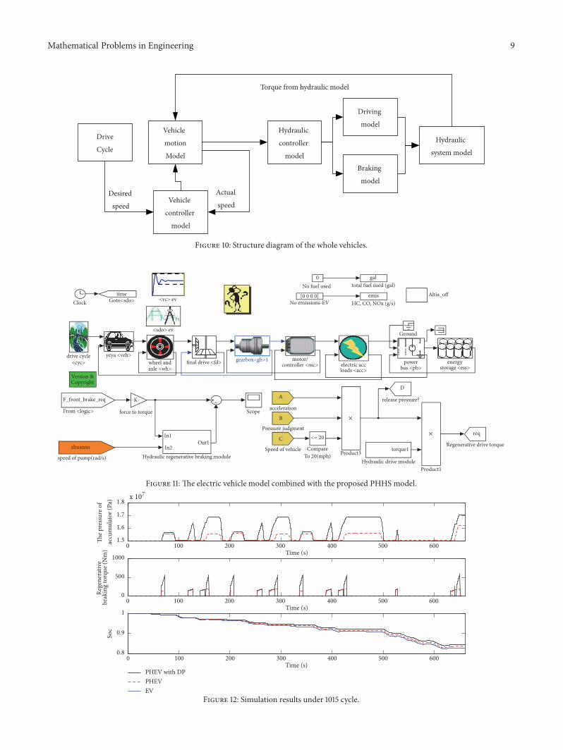
4.2. Simulation Results in ADVISOR. The structure diagramof the entire vehicles is comprised of drive cycle, vehiclecontroller model, vehicle motion model, hydraulic controllermodel, and PHHS model, as illustrated in Figure 10. In casethe regenerative braking is required, the brake model of thePHHS starts to operate, and the pump/motor operates inthe state of the pump to store the energy into the hydraulicaccumulator. When the vehicle starts or accelerates, the drivemodel of PHHS begins to work, the pump/motor works inthe state of the motor, and the hydraulic accumulator releasesthe stored energy. The torque exerted by the PHHS acts onthe vehicle motion model. The vehicle controller determinesthe vehicle input torque with a comparison of the differencebetween the actual running speed of the vehicle and thedesired speed from the drive cycle.
The displacement of the hydraulic pump and the ratio ofthe torque coupler are fixed without applying DP algorithm.The selection of displacement and transmission ratio isdetermined based on the following rules. The displacementof the hydraulic pump is 0.02L/r, and the ratio of thetorque coupler is 2.5 under the 1015 cycle condition. Thedisplacement of the hydraulic pump is 0.035L/r, and the ratioof the torque coupler is 2.5 in the UDDS cycle condition.With respect to the proposed optimization of energy recovery
Table 4: The amount of electricity consumed.
Cycle PHEV PHEV with DP Growth rate1015 0.165 0.156 5.4%UDDS 0.461 0.432 6.5%
efficiency algorithm, the hydraulic pump displacement andtorque coupler transmission ratio is established from the DPresults. The compared results between ‘with DP’ and ‘withoutDP’ in terms of 1015 cycle and UDDS cycle are shown inFigures 12 and 13, respectively.
The electric vehicle model incorporating the proposedPHHSmodel is built in ADVISOR as shown in Figure 11. Thedetailed vehicle parameters are listed in Table 3.
The simulation results derived from Figures 12 and 13demonstrate that the optimal strategy of the pump displace-ment and the torque coupler transmission ratio based on theDP algorithm is effective. As compared to the PHEV withoutDP, the efficiency of braking energy recovery is enhancedwiththe increased final pressure of the increasing accumulator andthe regenerative braking torque of PHHS. Compared withthe two drive cycles, the frequency of braking is lower, thestrength is smaller in 1015 drive cycle, and the maximumspeed of the vehicle stands at 43mph. In contrast, the brakingfrequency is higher, the braking strength is bigger in UDDSdrive cycle, and the maximum speed of the vehicle reaches 56mph. The amount of electricity consumed by the vehicle intwo different drive cycles is described in Table 4.
From Table 4, it is known that the vehicle makes a 5.4%saving on the electric amount using the DP algorithm in 1015drive cycle and a 6.5% saving on UDDS drive cycle comparedwith the PHEV without DP algorithm.
Mathematical Problems in Engineering 9
Drive
Cycle
Hydraulic
controller
model
Driving
model
Braking
model
Hydraulic
system model
Vehicle
controller
model
Torque from hydraulic model
Vehicle
motion
Model
Actual
speedDesired
speed
Figure 10: Structure diagram of the whole vehicles.
force to torque
wheel andaxle <wh>
galtotal fuel used (gal)
powerbus <pb>
motor/controller <mc>final drive <fd> energy
storage <ess>electric accloads <acc>
drive cycle<cyc>
0No fuel used
[0 0 0 0]No emissions-EV
Version &Copyright
emisHC, CO, NOx (g/s)
Ground
timeGoto<sdo>Clock
Altia_off<vc> ev
<sdo> ev
gearbox<gb>1yeya <veh>
Scope
F_front_brake_req
From <logic>
-K-
In1
In2Out1
Hydraulic regenerative braking module
zhuansu
speed of pump(rad/s)
A
acceleration
B
Pressure judgment
Product3
C
Speed of vehicle
<= 20
CompareTo 20(mph)
D
release pressure?
torque1
Hydraulic drive moduleProduct1
req
Regenerative drive torque
×
×
Figure 11: The electric vehicle model combined with the proposed PHHS model.
0 100 200 300 400 500 600Time (s)
The p
ress
ure o
f
0 100 200 300 400 500 600Time (s)
Rege
nera
tive
PHEV with DPPHEVEV
3000 100 200Time (s)
400 500 600
1
Soc
0
500
1000
brak
ing
torq
ue (N
m)
1.5
1.6
1.7
1.8
accu
mul
ator
(Pa)
x 107
0.9
0.8
Figure 12: Simulation results under 1015 cycle.

10 Mathematical Problems in Engineering
0 200 400 600 800 1000 1200Time (s)
The p
ress
ure o
f
0 200 400 600 800 1000 1200Time (s)
Rege
nera
tive
0 200 400 600 800 1000 1200Time (s)
PHEV with DPPHEVEV
x 107
0.4
0.6
0.8
1
Soc
0
500
1000
brak
ing
torq
ue (N
m)
1.4
1.6
1.8
2
accu
mul
ator
(Pa)
Figure 13: Simulation results under UDDS cycle.
5. Conclusions
This paper presents a DP-based optimal energy recoveryefficiency algorithm for PHHS. Global optimal solutionof displacement and transmission ratio under the knownurban drive cycles is obtained by taking the DP approach,where the cost function is defined as the total amountof energy recovery, and the displacement of the pumpand the transmission ratio of the torque coupler as thedecision variables. The PHHS bench test is performed toverify the PHHS Simulink model. Then, the whole parallelhydraulic hybrid vehicle model is established by integratingthe PHHS Simulink model into the ADVISOR. Finally, theimproved performance in terms of energy recovery efficiencyfor the proposed approach is validated. This performanceimprovement thus will lead to a significant reduction in fuelconsumption when driving on the road. Future work will bededicated to the design of the implementable strategy of brakeenergy recovery for a real parallel hydraulic hybrid bus basedon the results in this paper.
Conflicts of Interest
The authors declare that there are no conflicts of interestregarding the publication of this article.
Acknowledgments
This work is completed with support from the NationalNatural Science Foundation of China No. 51375452 and No.51405436.
References
[1] L. Guzzella and A. Sciarretta, Vehicle Propulsion Systems: Intro-duction to Modeling and Optimization, Springer, 2013.
[2] S. Baseley, C. Ehret, E. Greif, and M. G. Kliffken, “Hydraulichybrid systems for commercial vehicles,” in Proceedings of theSAE Commercial vehicle Engineering Congress & Exhibition,Rosemont, Ill, USA, 2007.
[3] M. A. Karbaschian and D. Soffker, “Review and comparison ofpower management approaches for hybrid vehicles with focuson hydraulic drives,” Energies, vol. 7, no. 6, pp. 3512–3536, 2014.
[4] N. Luo, J. Zhang, and J. Jiang, “Hydraulic hybrid technology,”Hydraulics Pneumatics & Seals, vol. 2, pp. 81–85, 2012.
[5] S. Baseley, C. Ehret, E. Greif, and M. G. Kliffken, “Hydraulichybrid systems for commercial vehicles,” SAE Paper, 2007.
[6] A. Delaney, “Hydraulic hybrids,” Engineering & Technology, vol.3, no. 20, pp. 40–43, 2008.
[7] V. Larsson, L. Johannesson, and B. Egardt, “Analytic solutionsto the dynamic programming subproblem in hybrid vehicleenergy management,” IEEE Transactions on Vehicular Technol-ogy, vol. 64, no. 4, pp. 1458–1467, 2015.
[8] X. Zeng and J. Wang, “A parallel hybrid electric vehicle energymanagement strategy using stochasticmodel predictive controlwith road grade preview,” IEEE Transactions on Control SystemsTechnology, vol. 99, pp. 1–8, 2015.
[9] V. Lu, C.-K. Chen, and C.-W. Hung, “Model predictive controlapproach for fuel economy improvement of a series hydraulichybrid vehicle,” Energies, vol. 7, no. 11, pp. 7017–7040, 2014.
[10] Z. Chen, C. C. Mi, R. Xiong, J. Xu, and C. You, “Energy man-agement of a power-split plug-in hybrid electric vehicle basedon genetic algorithm and quadratic programming,” Journal ofPower Sources, vol. 248, pp. 416–426, 2014.
[11] M. Sorrentino, G. Rizzo, and I. Arsie, “Analysis of a rule-basedcontrol strategy for on-board energy management of series

Mathematical Problems in Engineering 11
hybrid vehicles,”Control Engineering Practice, vol. 19, no. 12, pp.1433–1441, 2011.
[12] Y. Gao, L. Chen, and M. Ehsani, “Investigation of the effective-ness of regenerative braking for EV and HEV,” SAE Transac-tions, vol. 1, no. 8, pp. 3184–3190, 2000.
[13] T. Liu, Q.-H. Liu, and J.-H. Jiang, “Factors influencing regener-ative braking of parallel hydraulic hybrid vehicles,” Jilin DaxueXuebao (Gongxueban)/Journal of Jilin University (Engineeringand Technology Edition), vol. 40, no. 6, pp. 1473–1477, 2010.
[14] X. Ning, L. Ning, and J. Jun, “Experiment of energy recoveryefficiency and simulation research on EVs regenerative brakingsystem,” Computer Modelling and New Technologies, vol. 18, no.9, pp. 528–533, 2014.
[15] Y. Liu, D. Chen, Z. Lei et al., “Modeling and control of enginestarting for a full hybrid electric vehicle based on systemdynamic characteristics,” International Journal of AutomotiveTechnology, vol. 18, no. 5, pp. 911–922, 2017.
[16] S. Hui, “Multi-objective optimization for hydraulic hybrid vehi-cle based on adaptive simulated annealing genetic algorithm,”Engineering Applications of Artificial Intelligence, vol. 23, no. 1,pp. 27–33, 2010.
[17] H. Sun, J. Jiang, andX.Wang, “Parametersmatching and controlmethod of hydraulic hybrid vehicles with secondary regulationtechnology,” Chinese Journal of Mechanical Engineering, vol. 22,no. 1, pp. 57–63, 2009.
[18] L. Johannesson, M. Asbogard, and B. Egardt, “Assessing thepotential of predictive control for hybrid vehicle powertrainsusing stochastic dynamic programming,” IEEE Transactions onIntelligent Transportation Systems, vol. 8, no. 1, pp. 71–83, 2007.
[19] M. Keefe and T. Markel, “Dynamic programming applied toinvestigate energymanagement strategies for a Plug-inHEV,” inProceedings of the Conference EVS-22, Yokohama, Japan, 2006.
[20] X. Zhang and M. Chris, Vehicle Power Management: Modeling,Control And Optimization, Springer, 2011.
[21] W. Shen, J. Jiang, X. Su, and H. R. Karimi, “Parametermatchinganalysis of hydraulic hybrid excavators based on dynamicprogramming algorithm,” Journal of Applied Mathematics, vol.2013, Article ID 615608, 10 pages, 2013.
[22] T. Liu, J. Zheng, Y. Su, and J. Zhao, “A study on control strategyof regenerative braking in the hydraulic hybrid vehicle basedonECE regulations,”Mathematical Problems in Engineering, vol.2013, Article ID 208753, 9 pages, 2013.
[23] B. Skugor and J. Petric, “Optimization of control variables anddesign of management strategy for hybrid hydraulic vehicle,”Energies, vol. 11, no. 10, p. 2838, 2018.
[24] N. Li, X. Ning, Q. Wang, and J. Li, “Hydraulic regenerativebraking system studies based on a nonlinear dynamic model ofa full vehicle,” Journal ofMechanical Science andTechnology, vol.31, no. 5, pp. 2691–2699, 2017.
[25] D. Chindamo,M. Gadola, andM. Romano, “Simulation tool foroptimization and performance prediction of a generic hybridelectric series powertrain,” International Journal of AutomotiveTechnology, vol. 15, no. 1, pp. 135–144, 2014.
[26] D. Chindamo and M. Gadola, “What is the most representativestandard driving cycle to estimate diesel emissions of a lightcommercial vehicle?” in Proceedings of the 1st IFAC Workshopon Integrated Assessment Modelling for Environmental Systems,vol. 55, pp. 73–78, Brescia, Italy, 2018.

Hindawiwww.hindawi.com Volume 2018
MathematicsJournal of
Hindawiwww.hindawi.com Volume 2018
Mathematical Problems in Engineering
Applied MathematicsJournal of
Hindawiwww.hindawi.com Volume 2018
Probability and StatisticsHindawiwww.hindawi.com Volume 2018
Journal of
Hindawiwww.hindawi.com Volume 2018
Mathematical PhysicsAdvances in
Complex AnalysisJournal of
Hindawiwww.hindawi.com Volume 2018
OptimizationJournal of
Hindawiwww.hindawi.com Volume 2018
Hindawiwww.hindawi.com Volume 2018
Engineering Mathematics
International Journal of
Hindawiwww.hindawi.com Volume 2018
Operations ResearchAdvances in
Journal of
Hindawiwww.hindawi.com Volume 2018
Function SpacesAbstract and Applied AnalysisHindawiwww.hindawi.com Volume 2018
International Journal of Mathematics and Mathematical Sciences
Hindawiwww.hindawi.com Volume 2018
Hindawi Publishing Corporation http://www.hindawi.com Volume 2013Hindawiwww.hindawi.com
The Scientific World Journal
Volume 2018
Hindawiwww.hindawi.com Volume 2018Volume 2018
Numerical AnalysisNumerical AnalysisNumerical AnalysisNumerical AnalysisNumerical AnalysisNumerical AnalysisNumerical AnalysisNumerical AnalysisNumerical AnalysisNumerical AnalysisNumerical AnalysisNumerical AnalysisAdvances inAdvances in Discrete Dynamics in
Nature and SocietyHindawiwww.hindawi.com Volume 2018
Hindawiwww.hindawi.com
Di�erential EquationsInternational Journal of
Volume 2018
Hindawiwww.hindawi.com Volume 2018
Decision SciencesAdvances in
Hindawiwww.hindawi.com Volume 2018
AnalysisInternational Journal of
Hindawiwww.hindawi.com Volume 2018
Stochastic AnalysisInternational Journal of
Submit your manuscripts atwww.hindawi.com