Embed Size (px)
Citation preview

OPTIMIZATION OF COMPRESSED AIR IN THERMAL POWER PLANT-A NOVEL APPROACH.
RD Katre*, Ashish Bahety**, Daitary Tripathy**, Vishal laddha** *Sr, GM(C&I), Dy. Manager** (Control & Instrumentation) Jindal Power Limited, 4 X 250 MW, Tamnar.
Energy conservation is the burning issue now- a- days due to the tremendous scarcity of electricity across the world and sustainability of the globe. In order to reduce environmental pollution, either energy consumption should be reduced or energy should be generated more with higher efficiency and low auxiliary power consumption in power generation. In power plants, Compressor is the most inefficient auxiliary; therefore, specifically optimum use of compressed air is must. An attempt is therefore made to improve the optimum use of compressed air in this case study. Compressed air is used as a driving force for pneumatic instruments as a instrument air and for service air purpose in power plants. In addition to it, it is used for miscellaneous purpose like furnace Igniter’s cooling and cleaning. It is unaccounted and uncontrolled in most of the power plants. In the case study of JPL 4X250MW plant, during demand side management of compressed air, it is observed that there is a lion’s share of igniter cooling air in total compressed air consumption. Case study reflects that there is huge potential of saving in compressed air used for this purpose and the most potential conservation area for costly compressed air is Igniter Cooling and Cleaning System in PF boiler, which consumes about 1/3rd of the total air consumption quantity in the plant. This untouched area was explored for scope of reduction in air consumption; accordingly data was collected, analyzed and studied with collective wisdom. Incorporated modification with use of state of art technology, through which it is possible to monitor air consumption with high accuracy. Finally, succeeded in reduction of compressed air consumption quantity by 1135M3/Hr which saves about Rs 1.172cr annually.
Key words: Energy conservation, sustainability, compressed air, Igniter cooling, conversion efficiency.
INTRODUCTION: Auxiliary power consumption is considered as one of the major performance indices in thermal power plants. Generally, 6-10% of total generated power is consumed in the power plant itself for running various auxiliaries and processes. Air compressors accounts for significant amount of electricity ranges from 2 to 5 % of total auxiliary power consumption of the plant. Air compressors are used in a variety of industries to supply process requirements, to operate pneumatic tools and equipment, and to meet instrumentation needs. Only 10 – 30% of energy reaches the point of end-use, and balance 70 – 90% of energy of the power of the prime mover being converted to unusable heat energy and to a lesser extent lost in form of friction, misuse and noise.
APPLICATION OF COMPRESSED AIR:
Compressed air is mainly used in thermal power plants for following applications:-
A. Instrument air: It is used as driving fluid in pneumatic equipments and instruments used for control, protection, measurement and process applications. It requires high quality air free from dust, humidity and oil.
B. Service air: Pressurised air is used for cleaning and cooling activities in the plant.
C. Miscellaneous Process applications: It is used for air motors, L.D.O. atomization, igniter cooling etc.
“ National Seminar on TPP Performance Management” at JIPT, 2014 ” 1

CONFIGURATION OF COMPRESSED AIR SYSTEM:
O P Jindal Super Thermal Power Plant, Tamnar, Raigarh (C.G.) 4x250 MW plant has the common compressed air set up for the entire plant as shown in fig.No.-1. It comprises of three Nos. centrifugal compressors having capacity of 127nm3/min, and two screw compressor having capacity of 44nm3/min each. Prior to this setup it was 3 centrifugal compressors, with two compressors in loaded condition with some spare capacity and another one in unloaded condition. The need was felt to introduce two additional screw compressors as capacity optimization and in view to run one Nos. each centrifugal and screw compressor.
Fig-1 Schematic of compressed air system and its consumption pattern
In the journey of reduction in auxiliary power consumption, auxiliary wise consumption data was captured with the help of Energy management system (EMS). It is observed that, Air compressors monthly consumption is about1.2 MU i.e.2 % of total auxiliary power consumption of the plant.
Conventional methods like arresting leakages and wastage of air could not be relieved significantly but, this proved to be just beating around the bush and the energy scenario was same with two screw and one centrifugal compressor, hence there was a need to think out of the box and scratch grey cells to discover the high potential areas of energy consumption as well as exploit operating margins provided by manufacturer in equipment and it’s control. Systematic study of the system carried out. The efforts taken in this journey were proper experimental method with noncompromisation on stability, reliability and sustainability of the pneumatic system and overall plant.
The concerted team effort has given the result and the innovative approach applied is very much justified.“ National Seminar on TPP Performance Management” at JIPT, 2014 ”
2

Power consumption data captured from energy management system is as shown in table No.1
Date - 19-Apr-13
SL No. Name of Feeder Running Hours
MWH Consumption
Avg. PFAvg.
CurrentImport Export
1 AIR COMPRESSOR 01 24 19.09 0.00 0.92 75.3
2 AIR COMPRESSOR 02 0 0.00 _ 0.00 0.00
3 AIR COMPRESSOR 03 24 19.95 0.00 0.92 79.24
4 AIR COMPRESSOR 04 0 0.00 0.00 0.00 0.00
5 AIR COMPRESSOR 05 0 _ _ _ _
Total AIR COMPRESSORS 39.04 0
Date - 20-Apr-13
SL No. Name of Feeder Running Hours
MWH Consumption
Avg. PFAvg.
CurrentImport Export
1 AIR COMPRESSOR 01 24 18.79 0.00 0.92 75.33
2 AIR COMPRESSOR 02 0 0.00 _ 0.00 0.00
3 AIR COMPRESSOR 03 24 20.56 0.00 0.92 81.64
4 AIR COMPRESSOR 04 0 0.00 0.00 0.00 0.00
5 AIR COMPRESSOR 05 0 _ _ _ _
Total AIR COMPRESSORS 39.35 0
Date - 21-Apr-13
SL No. Name of Feeder Running Hours
MWH Consumption
Avg. PFAvg.
CurrentImport Export
1 AIR COMPRESSOR 01 24 18.79 0.00 0.92 75.31
2 AIR COMPRESSOR 02 0 0.00 _ 0.00 0.00
3 AIR COMPRESSOR 03 24 20.83 0.00 0.92 82.56
4 AIR COMPRESSOR 04 0 0.00 0.00 0.00 0.00
5 AIR COMPRESSOR 05 0 _ _ _ _
Total AIR COMPRESSORS 39.62 0 Table no.1-EMS data before control system optimization
JOURNEY TOWARDS SUCCESS:
Step-I Optimization of control system: One centrifugal compressor at full load and another on partial load was the normal plant operation. Partial loaded compressors bypass valve was getting open at 71 Amp minimum limits to meet out demand. Threshold limit optimized to 67 Amp gradually so that inlet valve position reduced for same discharge quantity and subsequently reduction in power consumption.
“ National Seminar on TPP Performance Management” at JIPT, 2014 ” 3

Date - 22-Apr-13
SL No. Name of Feeder Running Hours
MWH Consumption
Avg. PF Avg. CurrentImport Export
1 AIR COMPRESSOR 01 24 18.00 0.00 0.92 72.37
2 AIR COMPRESSOR 02 0 0.00 _ 0.00 0.00
3 AIR COMPRESSOR 03 24 19.37 0.00 0.92 80.84
4 AIR COMPRESSOR 04 0 0.00 0.00 0.00 0.00
5 AIR COMPRESSOR 05 0 _ _ _ _
Total AIR COMPRESSORS 37.37 0
Date - 23-Apr-13
SL No. Name of Feeder Running Hours
MWH Consumption
Avg. PF Avg. CurrentImport Export
1 AIR COMPRESSOR 01 24 17.36 0.00 0.92 70.17
2 AIR COMPRESSOR 02 0 0.00 _ 0.00 0.00
3 AIR COMPRESSOR 03 24 19.94 0.00 0.92 79.94
4 AIR COMPRESSOR 04 0 0.00 0.00 0.00 0.00
5 AIR COMPRESSOR 05 0 _ _ _ _
Total AIR COMPRESSORS 37.3 0
Date - 24-Apr-13
SL No. Name of Feeder Running Hours
MWH Consumption
Avg. PF Avg. CurrentImport Export
1 AIR COMPRESSOR 01 24 17.37 0.00 0.92 70.21
2 AIR COMPRESSOR 02 0 0.00 _ 0.00 0.00
3 AIR COMPRESSOR 03 24 19.64 0.00 0.92 78.52
4 AIR COMPRESSOR 04 0 0.00 0.00 0.00 0.00
5 AIR COMPRESSOR 05 0 _ _ _ _Total AIR COMPRESSORS 37.01 0
Table no.2-EMS data after control system optimization
Comparing both table no.1 and Table no.2, it directly shows that MWH consumption reduced from 39.5MWH to 37.4MWH after reducing threshold limit value of current, Effect of control system optimization reflects that there is saving of approx 2000 kWH per day.
Step- II Study of consumption pattern:
Measurement is the first step in any conservation activity. As compressed air is ancillary system in power generation plants, its instrumentation and control is also undermined compared to main plant. Here also, online flow measurement instruments were not installed properly or not properly calibrated. Hence, in a first stroke, all compressors discharge, instrument and service air header flow meters were made ready. Also, there was no flow meter installed in the header of igniter cooling and L.D.O. atomization air. It was not easy to get line shut down for installation of online air flow meter as it is the only source for all the four units. Hence individual compressor’s output, instrument and service air header flow actual measured and remaining igniter cooling line flow calculated from it.As shown in Fig. No.1 and table No.1 mWH consumption of compressor to support pneumatic requirement of 4X250MW at OPJSTPP stands at approx. 39.5mwh per day.
“ National Seminar on TPP Performance Management” at JIPT, 2014 ” 4

As per fig.1, before optimization of air pressure at igniter cooling and cleaning line, air flow was
1) Total air flow-8530m3/hr
2) Service air line flow-1250m3/hr
3) Instrument air line flow-4645m3/hr
4) Igniter cooling and cleaning line flow-2550m3/hr
Observations were very surprising and eye opener. Igniter cooling air was shortlisted as the major stakeholder; about31% in total compressed air consumption and targeted to explore any opportunity for conservation.
IGNITER COOLING AIR NECESSITY AND CONFIGURATION: High Energy Arc (HEA) Igniters are used in BHEL plants. It is used for igniting oil as a fuel in initial light up condition or in plant exigencies. Igniters are placed in each corner adjacent to oil guns. In 4X250 MW tangential coal fired furnace total 12 Nos. of igniter are used in all three elevations and four corners. Igniter comprises of guide pipe assembly, Igniter rod made up of stainless steel braided hose and fix rod, igniter spark tip and conducting Teflon coated cable inside the rod. Igniter rod moves inside guide pipe assembly in advance-retract direction. External cooling air is provided for protection of igniter components from excessive heating and as well as cleaning the passage between igniter and its assembly.
Igniter data sheet, general arrangement of igniter and cooling air arrangement is shown in igniter datasheet, Fig. No. 2, & 3
IGNITER ROD DATASHEET:
SPARK ROD PART No.Type & Model No Flexible / CBLS . 1000.025Operating Temp. 540C AT TIP,150 C AT CABLE END
Tube SS.304Flex Section SS.316Pin/ Socket BRASS/55-316
Insulation Of wire TEFLONInsulation Of Socket CERAMIC
Spark Tip 185 MMType & Model SEMI CONDUCTIVE TYPE &157.900.003
Operating Voltage 2000
Tip Life 106 sparks
Material SPECIAL ALLOYCasting SS.316
Tip SPECIAL ALLOYCoating SEMI CONDUCTIVE
“ National Seminar on TPP Performance Management” at JIPT, 2014 ” 5

Fig.2 HEA igniter arrangement
01-HEA RETRACTOR 8 INCH STROKE, 02-HEA FLEX SPARK ROD W/O TIP,
03-HEA SPARK TIP 04-HEA EXCITOR,
05-HEA FLEX CABLE ASSEMBLY 06-SS HOSE, 07-AIR SET W/MB
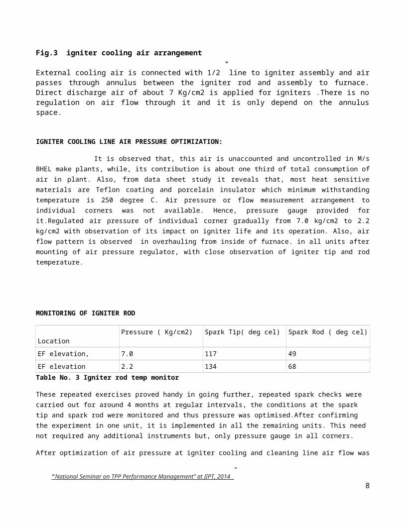
Fig.3 igniter cooling air arrangement
External cooling air is connected with 1/2” line to igniter assembly and air passes through annulus between the igniter rod and assembly to furnace. Direct discharge air of about 7 Kg/cm2 is applied for igniters .There is no regulation on air flow through it and it is only depend on the annulus space.
IGNITER COOLING LINE AIR PRESSURE OPTIMIZATION:
It is observed that, this air is unaccounted and uncontrolled in M/s BHEL make plants, while, its contribution is about one third of total consumption of air in plant. Also, from data sheet study it reveals that, most heat sensitive materials are Teflon coating and porcelain insulator which minimum withstanding temperature is 250 degree C. Air pressure or flow measurement arrangement to individual corners was not available. Hence, pressure gauge provided for it.Regulated air pressure of individual corner gradually from 7.0 kg/cm2 to 2.2 kg/cm2 with observation of its impact on igniter life and its operation. Also, air flow pattern is observed in overhauling from inside of furnace. in all units after mounting of air pressure regulator, with close observation of igniter tip and rod temperature.
“ National Seminar on TPP Performance Management” at JIPT, 2014 ” 6

MONITORING OF IGNITER ROD
LocationPressure ( Kg/cm2) Spark Tip( deg cel) Spark Rod ( deg cel)
EF elevation, 7.0 117 49
EF elevation 2.2 134 68
Table No. 3 Igniter rod temp monitor
These repeated exercises proved handy in going further, repeated spark checks were carried out for around 4 months at regular intervals, the conditions at the spark tip and spark rod were monitored and thus pressure was optimised.After confirming the experiment in one unit, it is implemented in all the remaining units. This need not required any additional instruments but, only pressure gauge in all corners.
After optimization of air pressure at igniter cooling and cleaning line air flow was
1) Total air flow-7410m3/hr
2) Service air line flow-1250m3/hr
3) Instrument air line flow-4645m3/hr
4) Igniter cooling and atomizing line flow-1415m3/hr
Sr. no. DESC. FLOW BEFORE REGULATION OF IGNITER COOLING LINE (6.5KG/CM2)
FLOW AFTER REGULATION OF IGNITER COOLING LINE (2.5KG/CM2)
SAVING IN FLOW(M3/HR)
1 IGNITER & ATOMISING AIR LINE FLOW
2550 M3/HR 1415 M3/HR 1135M3/HR
After completion of air pressure optimization at igniter air cooling line results are as below mentioned table
Report Type :- DailySummary Energy Report Date - 21-Oct-13
SL No. Name of Feeder Running HoursMWH
Consumption Avg. PFAvg.
Current
Import Export
1 AIR COMPRESSOR 01 24 0.00 0.00 0.00 0.00
2 AIR COMPRESSOR 02 0 20.76 _ 0.92 0.00
3 AIR COMPRESSOR 03 0 0.00 0.00 0.00 0.00
4 AIR COMPRESSOR 04 24 8.15 0.00 0.84 35.17
5 AIR COMPRESSOR 05 24 0.00 0.00 0.00 0.00
Total AIR COMPRESSORS 28.91 0
Total AIR COMPRESSORS 28.91 0
Table no.3-EMS data after air flow optimization at igniter cooling line “ National Seminar on TPP Performance Management” at JIPT, 2014 ”
7
ENERGY ECONOMICS:
SR.NO. NAME OF ACTIVITYBEFORE
CONSUMPTIONAFTER
CONSUMPTIONTOTAL
SAVINGSDATE OF
IMPLEMENTATION
1CONTROL SYSTEM
OPTIMIZATION 39.62MWH 37.02MWH 2.6MWH 22/04/2013
2IGNITER AIR COOLING LINE PRESSURE OPTIMIZATION 37.02MWH 28.91 MWH 8.11MWH 20/10/2013
TOTAL MWH SAVING PER DAY=39.62-28.91=10.71MWH/DAY
TOTAL MWH SAVING PER YEAR=10.71*365 =3909MWH
SO TOTAL KWH SAVING PER YEAR=3909*1000 =3909000KWH
TOTAL MONETARY SAVINGS PER YEAR=3909000*3=1.172Cr
JOURNEY STARTED WITH 39.5MWH/DAY AND AFTER COMPLETING THIS PROJECT CONSUMPTION IS 28.91MWH/DAY
Also, it is observed that, frequency of guns proving at single stroke improved a lot after optimization of air pressure. It may be due to elimination of cooling air curtaining around the spark. This is an additional inadvertent outcome of the activity. OTHER MEASURES FOR ENHANCING RELIABILITY AND STABILITY OF PNEUMATIC SYSTEM:
To provide isolating valve for less critical air supply like AHP, coal reject system, igniter air cooling line which needs to get closed in exigency conditions like black outs, compressor tripping etc .
Providing air accumulators at far/important pneumatic instruments to provide buffer stock during exigencies. In addition to above ,to identify and arrest air leakages
CONCLUSION: Since the task was done for probably first time in M/s BHEL plant and being novel, this can be considered as an exemplary success story to think out of the box and the result speaks.
This was an endeavor in Auxiliary Power Conservation in one of the most inefficient system .The measures discussed above were success story after huge brainstorming and many pitfalls. This may be an example for the upcoming and existing power plants which has more or less same system characteristics.
REFERENCES:
1) HEA igniter installation–DWG NO.-2-41-500-00320/REV 042) Igniter datasheet-cbl/combustion system:12-26470-DS013) Energy meter reading-energy management system supplied by arreva4) Compressor datasheet –OEM/IR
“ National Seminar on TPP Performance Management” at JIPT, 2014 ” 8