Embed Size (px)
Citation preview
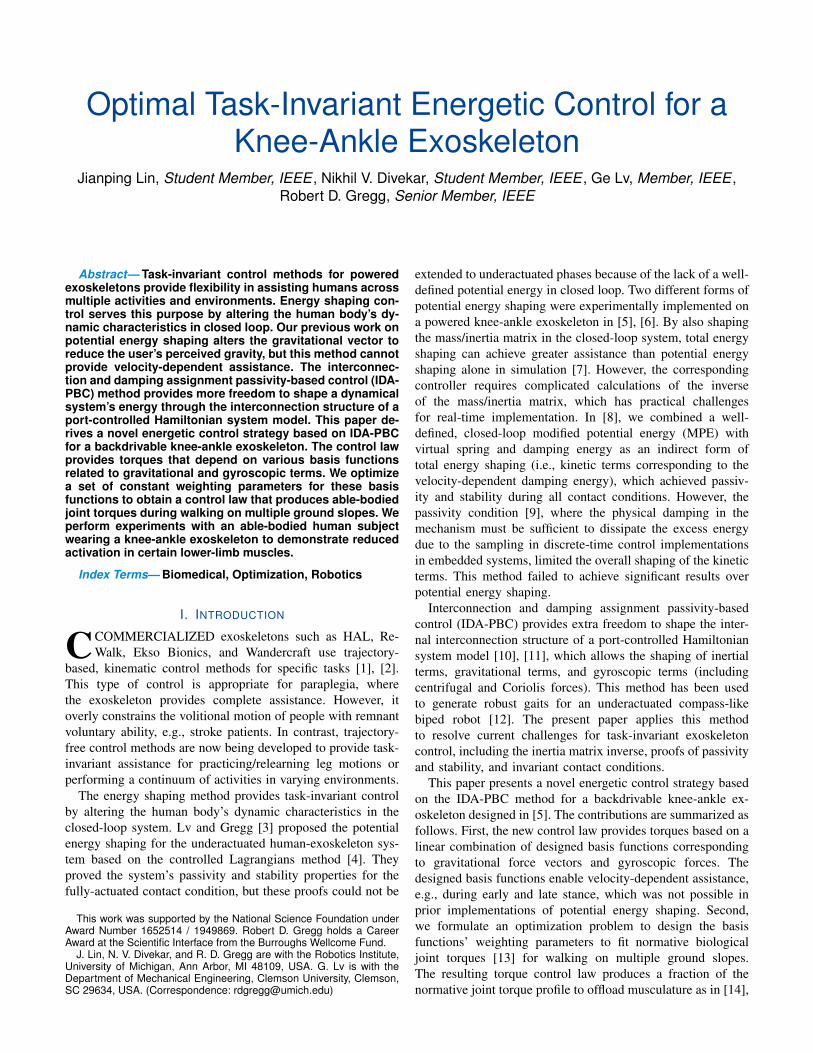
Optimal Task-Invariant Energetic Control for aKnee-Ankle Exoskeleton
Jianping Lin, Student Member, IEEE , Nikhil V. Divekar, Student Member, IEEE , Ge Lv, Member, IEEE ,Robert D. Gregg, Senior Member, IEEE
Abstract— Task-invariant control methods for poweredexoskeletons provide flexibility in assisting humans acrossmultiple activities and environments. Energy shaping con-trol serves this purpose by altering the human body’s dy-namic characteristics in closed loop. Our previous work onpotential energy shaping alters the gravitational vector toreduce the user’s perceived gravity, but this method cannotprovide velocity-dependent assistance. The interconnec-tion and damping assignment passivity-based control (IDA-PBC) method provides more freedom to shape a dynamicalsystem’s energy through the interconnection structure of aport-controlled Hamiltonian system model. This paper de-rives a novel energetic control strategy based on IDA-PBCfor a backdrivable knee-ankle exoskeleton. The control lawprovides torques that depend on various basis functionsrelated to gravitational and gyroscopic terms. We optimizea set of constant weighting parameters for these basisfunctions to obtain a control law that produces able-bodiedjoint torques during walking on multiple ground slopes. Weperform experiments with an able-bodied human subjectwearing a knee-ankle exoskeleton to demonstrate reducedactivation in certain lower-limb muscles.
Index Terms— Biomedical, Optimization, Robotics
I. INTRODUCTION
CCOMMERCIALIZED exoskeletons such as HAL, Re-Walk, Ekso Bionics, and Wandercraft use trajectory-
based, kinematic control methods for specific tasks [1], [2].This type of control is appropriate for paraplegia, wherethe exoskeleton provides complete assistance. However, itoverly constrains the volitional motion of people with remnantvoluntary ability, e.g., stroke patients. In contrast, trajectory-free control methods are now being developed to provide task-invariant assistance for practicing/relearning leg motions orperforming a continuum of activities in varying environments.
The energy shaping method provides task-invariant controlby altering the human body’s dynamic characteristics in theclosed-loop system. Lv and Gregg [3] proposed the potentialenergy shaping for the underactuated human-exoskeleton sys-tem based on the controlled Lagrangians method [4]. Theyproved the system’s passivity and stability properties for thefully-actuated contact condition, but these proofs could not be
This work was supported by the National Science Foundation underAward Number 1652514 / 1949869. Robert D. Gregg holds a CareerAward at the Scientific Interface from the Burroughs Wellcome Fund.
J. Lin, N. V. Divekar, and R. D. Gregg are with the Robotics Institute,University of Michigan, Ann Arbor, MI 48109, USA. G. Lv is with theDepartment of Mechanical Engineering, Clemson University, Clemson,SC 29634, USA. (Correspondence: [email protected])
extended to underactuated phases because of the lack of a well-defined potential energy in closed loop. Two different forms ofpotential energy shaping were experimentally implemented ona powered knee-ankle exoskeleton in [5], [6]. By also shapingthe mass/inertia matrix in the closed-loop system, total energyshaping can achieve greater assistance than potential energyshaping alone in simulation [7]. However, the correspondingcontroller requires complicated calculations of the inverseof the mass/inertia matrix, which has practical challengesfor real-time implementation. In [8], we combined a well-defined, closed-loop modified potential energy (MPE) withvirtual spring and damping energy as an indirect form oftotal energy shaping (i.e., kinetic terms corresponding to thevelocity-dependent damping energy), which achieved passiv-ity and stability during all contact conditions. However, thepassivity condition [9], where the physical damping in themechanism must be sufficient to dissipate the excess energydue to the sampling in discrete-time control implementationsin embedded systems, limited the overall shaping of the kineticterms. This method failed to achieve significant results overpotential energy shaping.
Interconnection and damping assignment passivity-basedcontrol (IDA-PBC) provides extra freedom to shape the inter-nal interconnection structure of a port-controlled Hamiltoniansystem model [10], [11], which allows the shaping of inertialterms, gravitational terms, and gyroscopic terms (includingcentrifugal and Coriolis forces). This method has been usedto generate robust gaits for an underactuated compass-likebiped robot [12]. The present paper applies this methodto resolve current challenges for task-invariant exoskeletoncontrol, including the inertia matrix inverse, proofs of passivityand stability, and invariant contact conditions.
This paper presents a novel energetic control strategy basedon the IDA-PBC method for a backdrivable knee-ankle ex-oskeleton designed in [5]. The contributions are summarized asfollows. First, the new control law provides torques based on alinear combination of designed basis functions correspondingto gravitational force vectors and gyroscopic forces. Thedesigned basis functions enable velocity-dependent assistance,e.g., during early and late stance, which was not possible inprior implementations of potential energy shaping. Second,we formulate an optimization problem to design the basisfunctions’ weighting parameters to fit normative biologicaljoint torques [13] for walking on multiple ground slopes.The resulting torque control law produces a fraction of thenormative joint torque profile to offload musculature as in [14],
(𝒑𝒑𝒙𝒙,𝒑𝒑𝒚𝒚)𝒙𝒙
𝒚𝒚
−𝜽𝜽𝒉𝒉
𝝓𝝓
𝜽𝜽𝒌𝒌
𝜽𝜽𝒔𝒔𝒌𝒌
𝜽𝜽𝒔𝒔𝒔𝒔
𝜽𝜽𝒔𝒔
𝝉𝝉𝒛𝒛
−𝒇𝒇𝒚𝒚𝒇𝒇𝒙𝒙
𝑰𝑰𝑰𝑰𝑰𝑰 = 𝑪𝑪𝑪𝑪𝑪𝑪
(𝒉𝒉𝒙𝒙,𝒉𝒉𝒚𝒚)
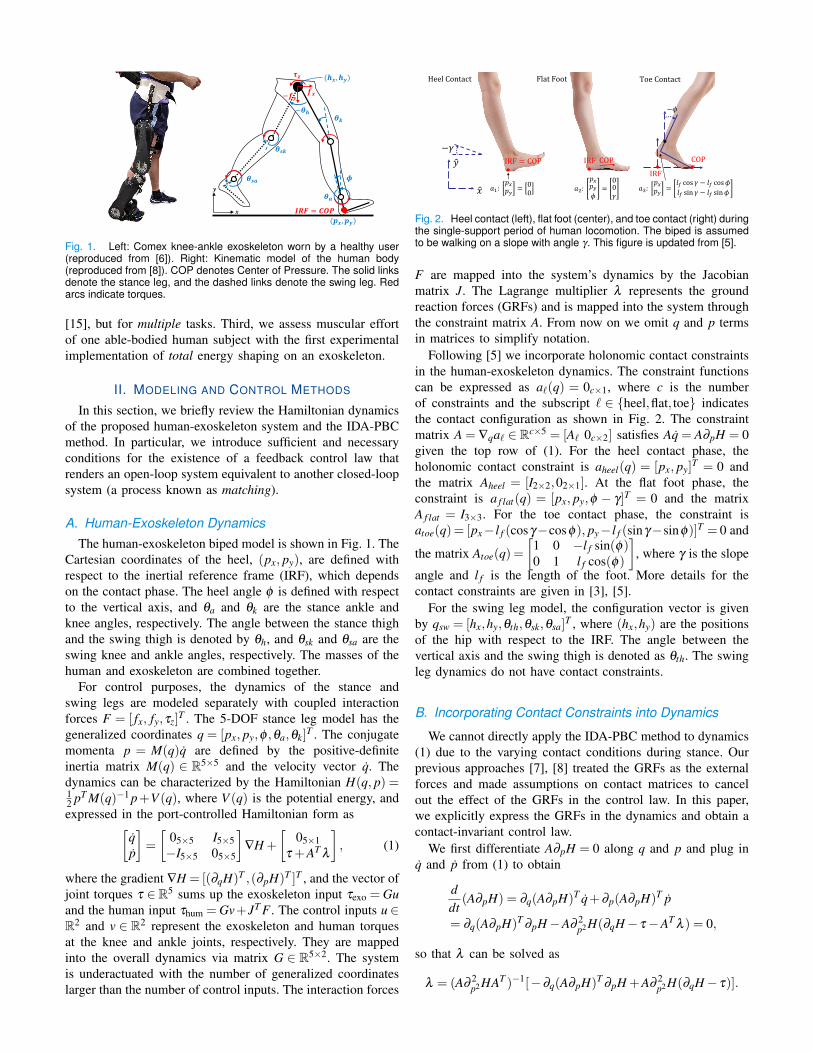
Fig. 1. Left: Comex knee-ankle exoskeleton worn by a healthy user(reproduced from [6]). Right: Kinematic model of the human body(reproduced from [8]). COP denotes Center of Pressure. The solid linksdenote the stance leg, and the dashed links denote the swing leg. Redarcs indicate torques.
[15], but for multiple tasks. Third, we assess muscular effortof one able-bodied human subject with the first experimentalimplementation of total energy shaping on an exoskeleton.
II. MODELING AND CONTROL METHODS
In this section, we briefly review the Hamiltonian dynamicsof the proposed human-exoskeleton system and the IDA-PBCmethod. In particular, we introduce sufficient and necessaryconditions for the existence of a feedback control law thatrenders an open-loop system equivalent to another closed-loopsystem (a process known as matching).
A. Human-Exoskeleton DynamicsThe human-exoskeleton biped model is shown in Fig. 1. The
Cartesian coordinates of the heel, (px, py), are defined withrespect to the inertial reference frame (IRF), which dependson the contact phase. The heel angle φ is defined with respectto the vertical axis, and θa and θk are the stance ankle andknee angles, respectively. The angle between the stance thighand the swing thigh is denoted by θh, and θsk and θsa are theswing knee and ankle angles, respectively. The masses of thehuman and exoskeleton are combined together.
For control purposes, the dynamics of the stance andswing legs are modeled separately with coupled interactionforces F = [ fx, fy,τz]
T . The 5-DOF stance leg model has thegeneralized coordinates q = [px, py,φ ,θa,θk]
T . The conjugatemomenta p = M(q)q are defined by the positive-definiteinertia matrix M(q) ∈ R5×5 and the velocity vector q. Thedynamics can be characterized by the Hamiltonian H(q, p) =12 pT M(q)−1 p+V (q), where V (q) is the potential energy, andexpressed in the port-controlled Hamiltonian form as[
qp
]=
[05×5 I5×5−I5×5 05×5
]∇H +
[05×1
τ +AT λ
], (1)
where the gradient ∇H = [(∂qH)T ,(∂pH)T ]T , and the vector ofjoint torques τ ∈R5 sums up the exoskeleton input τexo = Guand the human input τhum = Gv+JT F . The control inputs u∈R2 and v ∈ R2 represent the exoskeleton and human torquesat the knee and ankle joints, respectively. They are mappedinto the overall dynamics via matrix G ∈ R5×2. The systemis underactuated with the number of generalized coordinateslarger than the number of control inputs. The interaction forces
A1: Incorporating Contact Constraints
𝑎𝑎3:𝑝𝑝𝑥𝑥𝑝𝑝𝑦𝑦 =
𝑙𝑙𝑓𝑓 cos 𝛾𝛾 − 𝑙𝑙𝑓𝑓 cos𝜙𝜙𝑙𝑙𝑓𝑓 sin 𝛾𝛾 − 𝑙𝑙𝑓𝑓 sin𝜙𝜙
IRF = COP IRF COP
−𝜙𝜙
COP
𝑎𝑎2:𝑝𝑝𝑥𝑥𝑝𝑝𝑦𝑦𝜙𝜙
=00𝛾𝛾
𝑎𝑎1:𝑝𝑝𝑥𝑥𝑝𝑝𝑦𝑦 = 0
0
Heel Contact Flat Foot Toe Contact
�𝑥𝑥
�𝑦𝑦−𝛾𝛾
IRF
Fig. 2. Heel contact (left), flat foot (center), and toe contact (right) duringthe single-support period of human locomotion. The biped is assumedto be walking on a slope with angle γ. This figure is updated from [5].
F are mapped into the system’s dynamics by the Jacobianmatrix J. The Lagrange multiplier λ represents the groundreaction forces (GRFs) and is mapped into the system throughthe constraint matrix A. From now on we omit q and p termsin matrices to simplify notation.
Following [5] we incorporate holonomic contact constraintsin the human-exoskeleton dynamics. The constraint functionscan be expressed as a`(q) = 0c×1, where c is the numberof constraints and the subscript ` ∈ {heel,flat, toe} indicatesthe contact configuration as shown in Fig. 2. The constraintmatrix A = ∇qa` ∈ Rc×5 = [A` 0c×2] satisfies Aq = A∂pH = 0given the top row of (1). For the heel contact phase, theholonomic contact constraint is aheel(q) = [px, py]
T = 0 andthe matrix Aheel = [I2×2,02×1]. At the flat foot phase, theconstraint is a f lat(q) = [px, py,φ − γ]T = 0 and the matrixA f lat = I3×3. For the toe contact phase, the constraint isatoe(q)= [px− l f (cosγ−cosφ), py− l f (sinγ−sinφ)]T = 0 and
the matrix Atoe(q) =[
1 0 −l f sin(φ)0 1 l f cos(φ)
], where γ is the slope
angle and l f is the length of the foot. More details for thecontact constraints are given in [3], [5].
For the swing leg model, the configuration vector is givenby qsw = [hx,hy,θth,θsk,θsa]
T , where (hx,hy) are the positionsof the hip with respect to the IRF. The angle between thevertical axis and the swing thigh is denoted as θth. The swingleg dynamics do not have contact constraints.
B. Incorporating Contact Constraints into Dynamics
We cannot directly apply the IDA-PBC method to dynamics(1) due to the varying contact conditions during stance. Ourprevious approaches [7], [8] treated the GRFs as the externalforces and made assumptions on contact matrices to cancelout the effect of the GRFs in the control law. In this paper,we explicitly express the GRFs in the dynamics and obtain acontact-invariant control law.
We first differentiate A∂pH = 0 along q and p and plug inq and p from (1) to obtain
ddt(A∂pH) = ∂q(A∂pH)T q+∂p(A∂pH)T p
= ∂q(A∂pH)T∂pH−A∂
2p2H(∂qH− τ−AT
λ ) = 0,
so that λ can be solved as
λ = (A∂2p2HAT )−1[−∂q(A∂pH)T
∂pH +A∂2p2H(∂qH− τ)].

Plugging λ into (1) and setting W = (A∂ 2p2HAT )−1 ∈ Rc×c,[
qp
]=
[0 I
−I +ATWA∂ 2p2H −ATW∂q(A∂pH)T
]∇H
+
[0
(I−ATWA∂ 2p2H)(Gu+Gv+ JT F)
].
We can augment the above system in the port-controlledHamiltonian form [11], where[
qp
]= J ∇H +
[0
Gλ (u+ v)+ JTλ
F
].
The skew-symmetric matrix J =−J T is defined as
J =
[0 XT
λ
−Xλ Yλ
], Xλ = I−ATWA∂
2p2H,
Yλ =−ATW∂q(A∂pH)T +∂q(A∂pH)WA,
where we apply A∂pH = 0 to obtain the upper-right blockof the matrix J . The matrix J reveals the internal inter-connection structure of the open-loop dynamics, and matricesGλ = Xλ G and JT
λ= Xλ JT are defined respectively.
C. Matching Condition with Constrained DynamicsAssume we have closed the feedback loop for exoskeleton
input u, while the human inputs v and F remain open-loopin the Hamiltonian system. We consider a desired, closed-loop Hamiltonian H(p,q) = 1
2 pT M−1 p+V , where V =V +Vrepresents the new potential energy with shaping term V .The corresponding gravitational vector is N = ∇qV = ∇qV +∇qV = N + N. We set M = M to simplify the matchingprocess and avoid complicated calculations of the inverse ofthe mass/inertia matrix in the control law. However, we willstill achieve velocity-dependent shaping through the intercon-nection structure of the closed-loop Hamiltonian system. Thedesired closed-loop dynamics based on H are[
qp
]=
[0 I−I J2
]∇H +
[0
Gv+ JT F +AT λ
], (2)
where the skew-symmetric matrix J2 represents the extra DOFprovided by the IDA-PBC method, and
λ =(A∂2p2HAT )−1{−∂q(A∂pH)T
∂pH
+A∂2p2H[∂qH− J2∂pH−Gv− JT F ]}.
Plugging λ into (2), we have[qp
]=J ∇H +
[0
Gλ
v+ JTλ
F
],
where J = −J T =
[0 XT
λ
−Xλ
Yλ
]is a skew-symmetric ma-
trix describing the internal interconnection structure of theclosed-loop system with X
λ= Xλ , and Y
λ= −Y T
λ= J2 −
ATW [∂q(A∂pH)T + A∂ 2p2HJ2] + [JT
2 ∂ 2p2HAT + ∂q(A∂pH)]WA.
Matrices Gλ
and Jλ
are equivalent to Gλ and Jλ .Based on standard results in [16], Hamiltonian systems (1)
and (2) match if we have
Gλ u =−Xλ (∂qH−∂qH)+(Yλ−Yλ )∂pH,
=Xλ (−∂qH +∂qH + J2∂pH),
which yields the corresponding matching condition as
0 = G⊥λ
Xλ (−∂qH +∂qH + J2∂pH), (3)
where G⊥λ∈R3×5 is the (full-rank) left annihilator of Gλ , i.e.,
G⊥λ
Gλ = 0.To solve the matching condition (3), we express Xλ explic-
itly by decomposing M into four sub-matrices as
M =
[M1 M2MT
2 M4
],
where M1 ∈ R3×3 and M4 ∈ R2×2. Then we obtain
M−1 =
[∆−1 −∆−1M2M−1
4−M−1
4 MT2 ∆−1 M−1
4 +M−14 MT
2 ∆−1M2M−14
],
where ∆ = M1 −M2M−14 MT
2 . As a result, we have W =(A∆−1AT )−1 and Xλ can be expressed as
Xλ =
[I3×3−Zλ Zλ M2M−1
40 I2×2
],
where Zλ = AT` WA`∆
−1. Plugging Xλ into Gλ , we have Gλ =[M−1
4 MT2 ZT
λI2×2]
T and the corresponding left annihilator G⊥λ
equals [I3×3 −Zλ M2M−14 ]. Plugging in G⊥
λand Xλ , we have
the following solution of the matching condition (3) as
0 =[I3×3−Zλ 03×2
][−∂qH +∂qH + J2∂pH],
=[I3×3−Zλ 03×2
][−N +N + J2M−1 p]. (4)
By zeroing the unactuated parts (first three elements) of −N+N + J2M−1 p, the matching condition (3) is satisfied.
The above solution is equivalent to the results in [8], wherewe treated the GRFs as external forces and assumed thereexists a mapping of the GRFs between the open-loop andclosed-loop systems. Here, we incorporate the GRFs into thesystem’s dynamics to enable proofs of passivity and stabilitywithout making assumptions on the GRFs.
D. Shaping Strategies and Control LawAs mentioned in [8], a proper potential energy V exists in
the closed-loop system when the gravitational forces vector Nis well-defined with a symmetric Jacobian matrix, i.e., ∂ Ni
∂q j=
∂ N j∂qi
for any i, j ∈ {1, · · · ,5}. This closed-loop potential energycan then be retrieved by the variable gradient method [17],even during the underactuated phases.
The interconnection structure J2 provides extra freedom tointroduce artificial gyroscopic terms QT ∂pH, where Q is asmooth vector-valued function, and J2 = (∂qQ)T − ∂qQ. Theartificial gyroscopic terms QT ∂pH are linear in the p-variables(the momenta). As mentioned in [10], Q(q) must depend onlyon the coordinates q for the closed-loop system (2) to beintegrable, i.e., there exists an equivalent Lagrangian L(q, q) =12 qT Mq+ qT Q(q)− V to ensure passivity. Given the solution(4), the shapeable structure of the closed-loop Hamiltoniansystem is characterized below.
Proposition 2.1: The closed-loop system (2) is integrablewith a well-defined potential energy if the unactuated partsof N and Q are zero, and the actuated parts dependonly on the actuated state variables. For the stance leg

model, this means N = [0,0,0, N4(θa,θk), N5(θa,θk)]T and Q=
[0,0,0,Q4(θa,θk),Q5(θa,θk)]T .
The proof follows by checking the skew-symmetry propertyof the J2 matrix and the symmetry of the Jacobian matrix ∂qNin the solution (4).
The control law with the feasible shaping structure is
u = G+(∂qH−∂qH + J2M−1 p), (5)
with G+ = (GT G)−1GT being the left pseudoinverse of G.This IDA-PBC method is more general than the controllerin [8] by including artificial gyroscopic terms that achievevelocity-dependent shaping without affecting the system’skinetic energy due to the skew-symmetry of J2.
We can form multiple basis functions for the shapingterms in (5) as long as Proposition 2.1 is satisfied, whichconverts our controller design into an optimization process tofit the normative joint moment data in [13]. Importantly, thebasis functions have physical meanings that correspond to thegravitational vector and the gyroscopic forces that act withinthe system, resulting in an integrable Hamiltonian system.These basis functions aim to change the effect of these forcesand capture the essential characteristics of walking.
We design N = −α1ξ1 − ·· · − αiξi and J2M−1 p =αi+1ξi+1 + · · ·+ αwξw as linear combinations of the basisfunctions {ξ1,ξ2, . . . ,ξw}, where ξi ∈ R5×1 and w is the totalnumber of basis functions. We express the torque control inputu = G+(−N + J2M−1 p) = G+(α1ξ1 + α2ξ2 + · · ·+ αwξw) =Φ(q, p)α . We then optimize the constant coefficients α so theoutputs of control law u best fit normative human joint torquesy when inputting normative human kinematic trajectories [13].
The optimization problem is defined as
argminα
∑ j[U(q j, p j,α)−Yj]TWj[U(q j, p j,α)−Yj]
+U(0,0,α)TWrU(0,0,α)
where the objective function corresponds to the least squareerror of the exoskeleton control inputs U ∈ Rm×1 and thenormative human joint torques Yj ∈ Rm×1 with the weightingmatrix Wj and the number of time samples m. The subscript jrepresents the number of different walking tasks, includinglevel-ground walking and ramp walking. The state vectorsq j, p j ∈ Rm×1 comprise samples over time for the given taskj. We also include Wr for regulation with zero states q = 0and p = 0, where minimal torques should be provided.
A closed-form solution of the optimal coefficients α can beeasily obtained as α∗ = (ΦTWΦ)−1ΦTWY . As a result, thecorresponding control law equals u = Φ(q, p)α∗, which willbe scaled down to a desired fraction of normative torque.
E. Passivity and StabilityWe now explore the input-output passivity and stability
results of the exoskeleton-human system.Proposition 2.2: The closed-loop system (2) is passive from
the human input τhum to the output ∂pH.Proof: We can choose the total energy E(q, p) = H as a
storage function [17]. The time derivative of E(q, p) is
E = ∇HT[
qp
]= (∂pH)T
τhum +(∂pH)T ATλ = (∂pH)T
τhum,
where we use the skew-symmetry property of the intercon-nection structure and (∂pH)T AT λ = 0 due to the fact thatconstraint forces do no work [18].
Input-output passivity implies that the energy growth ofthe coupled human-exoskeleton system is controlled by thehuman. This provides safe interaction with the exoskeleton,but stability depends on the human control law. We examinestability of the closed-loop system around an equilibrium pointin a similar way to [8]. The equilibrium point (q?,0) is the statewhere the forces along the shaped potential energy balance themuscular forces and the ground reaction forces, i.e., Xλ N−Xλ τhum = 0. We make the common assumption that the humanis modulating joint impedance where τhum =−Kpe−Kd e [5].The constant diagonal matrices Kp, Kd are positive semi-definite, and e = q− q represents the difference between qand the human’s set-point vector q (which is not necessarilythe same as the equilibrium q? in impedance control). We cannow state Proposition 2.3.
Proposition 2.3: Consider the closed-loop system (2), theequilibrium point (q?,0) is stable in the sense of Lyapunovgiven human input τhum =−Kpe−Kd e.
Proof: We can set the Lyapunov function to be
V (q, p) = H +12
eT Kpe+∫ q
q0
A(s)Tλ (s,0) ·ds−V 0, (6)
where q0 is the state at t = 0 and V 0 is a constant suchthat V is positive definite and vanishes at the equilibriumpoint (q?,0). The Lyapunov function V achieves its minimalpoint when ∂pV = q = p = 0 and ∂qV = N +Kpe+AT λ =Xλ N−Xλ τhum = 0, i.e., at the equilibrium point (q?,0). Theincorporation of
∫ qq0
A(s)T λ (s,0) · ds guarantees the appear-ance of the GRFs to balance the unactuated parts of N atthe equilibrium state when ∂qV (q,0) = 0. As a result, theLyapunov function V is positive definite and vanishes only atthe equilibrium point (q?,0).
The time-derivative of Lyapunov function (6) is
V =∇HT[
qp
]+ qT Kpe+ qT AT
λ (q,0) =−qT Kd q≤ 0,
which shows that the shaped system is Lyapunov stable.Although asymptotic stability has not been guaranteed,
Lyapunov stability ensures the response will remain in aneighborhood of the equilibrium under human impedancecontrol. This result satisfies our control objective of partialtorque assistance while the human controls their kinematics.
III. RESULTS
We now show optimization results to demonstrate theproposed controller’s ability to recreate normative torquesfor three different ground slopes. We also experimentallyimplement the controller on a knee-ankle exoskeleton usedby a healthy human subject as a proof-of-concept.
A. Design OptimizationThe internal gyroscopic force term of the system includes
centrifugal and Coriolis forces. Together with the gravitationalvector N, these forces are expressed as trigonometric functionsof state variables. As a result, we choose the basis functions in
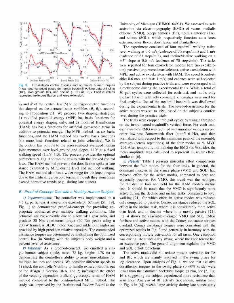
Fig. 3. Exoskeleton control torques and normative human torques(mean and variance) based on human treadmill walking data at incline(10◦), level ground (0◦), and decline (−10◦) at 1m/s. Positive valuesrepresent ankle dorsiflexion and knee extension.
J2 and N of the control law (5) to be trigonometric functionsthat depend on the actuated state variables (θa,θk), accord-ing to Proposition 2.1. We propose two shaping strategies:1) modified potential energy (MPE) has basis functions forpotential energy shaping only, and 2) modified Hamiltonian(HAM) has basis functions for artificial gyroscopic terms inaddition to potential energy. The MPE method has six basisfunctions, and the HAM method has twelve basis functions(six more basis functions related to joint velocities). We fitthe control law outputs to the across-subject averaged humanjoint moments over level-ground and slopes ±10◦ at a fixedwalking speed (1m/s) [13]. The process provides the optimalparameters α . Fig. 3 shows the results with the derived controllaws. The HAM method prevents the dorsiflexion spike at latestance exhibited by MPE during level and inclined walking.The HAM method also has a wider range for the knee torquesdue to the artificial gyroscopic terms, although they sometimesexceed normative trends (e.g., during late stance).
B. Proof-of-Concept Test with a Healthy Human Subject
1) Implementation: The controller was implemented on a4.5 kg partial-assist knee-ankle exoskeleton (Comex [5], [19],Fig. 1) to demonstrate proof-of-concept for providing ap-propriate assistance over multiple walking conditions. Theactuators are backdrivable due to a low 24:1 gear ratio, andproduce 30 Nm continuous torque (60 Nm peak) using a200 W frameless BLDC motor. Knee and ankle joint angles areprovided by high-precision relative encoders. The commandedassistance torques are determined by multiplying the optimizedcontrol law (in Nm/kg) with the subject’s body weight and apercent level-of-assistance.
2) Methods: As a proof-of-concept, we enrolled a sin-gle human subject (male, mass: 78 kg, height: 1.78 m) todemonstrate the controller’s ability to assist musculature formultiple inclines and speeds. We consider different speeds to1) check the controller’s ability to handle extra conditions outof the design in Section III-A, and 2) investigate the effectof the velocity-dependent artificial gyroscopic terms of HAMmethod compared to the position-based MPE method. Thestudy was approved by the Institutional Review Board at the
University of Michigan (HUM00164931). We assessed muscleactivation via electromyography (EMG) of vastus medialisoblique (VMO), biceps femoris (BF), tibialis anterior (TA),and soleus (SOL), which respectively function as a kneeextensor, knee flexor, dorsiflexor, and plantarflexor.
The experiment consisted of four treadmill walking tasks:level walking at 0.6 m/s (cadence of 70 steps/min) and 1 m/s(cadence of 83 steps/min), and incline/decline walking on a±5◦ slope at 0.6 m/s (cadence of 70 steps/min). The taskswere repeated for four exoskeleton modes: bare (no exoskele-ton), passive (unpowered exoskeleton), active exoskeleton withMPE, and active exoskeleton with HAM. The speed (comfort-able: 0.6 m/s, and fast: 1 m/s) and cadence were self-selectedby the subject during practice trials and were encouraged witha metronome during the experimental trials. While a total of30 gait cycles were collected for each task and mode, onlythe last 10 with relatively consistent kinematics were used forfinal analysis. Use of the treadmill handrails was disallowedduring the experimental trials. The level-of-assistance for theactive modes was set to 15%, based on the subject’s comfortlevel during the practice trials.
The trials were cropped into gait cycles by using a thresholdon the instrumented treadmill’s vertical force. For each task,each muscle’s EMG was rectified and smoothed using a secondorder low-pass Butterworth filter (cutoff 6 Hz), and thennormalized with respect to the maximum peak of the ensembleaverages (across repetitions) of the four modes as % MVC[20]. After temporally normalizing the EMG (as % stride), themean amplitude was calculated to represent muscular effort,similar to [6].
3) Results: Table I presents muscular effort comparisonsbetween the four modes for the four tasks. In general, thedominant muscles in the stance phase (VMO and SOL) hadreduced effort for the active modes, compared to bare andespecially passive. For VMO, this trend was the strongestfor the decline task and held for the HAM mode’s inclinetask. It should be noted that the VMO is significantly moreactive during the decline and incline tasks, compared to levelwalking [21], for which effort in active modes was reducedonly compared to passive. Comex assistance reduced the SOLeffort in the incline task, where it is considerably more activethan level, and in decline where it is mostly passive [21].Fig. 4 shows the ensemble-averaged VMO and SOL EMGsfor bare and active modes, with the Comex assistance torquesoverlaid. Comex assistance torques were consistent with theoptimized results in Fig. 3 and generally in harmony with thecorresponding muscle activations for all tasks. One exceptionwas during late stance-early swing, where the knee torque hadan excessive peak. The general alignment explains the VMOand SOL effort reductions.
The active modes did not reduce muscle activation for TAand BF, which are mainly involved in the swing phase forleg clearance. Upon analysis of Fig. 4, we see that assistivedorsiflexion torques in the swing phase (> 60% stride) werelower than the estimated backdrive torque (3 Nm, see [5, Fig.16]), suggesting the subject experienced more resistance thanassistance. Analysis of BF activity (not shown, similar trendto Fig. 4 in [6]) reveals large activity during late stance-early
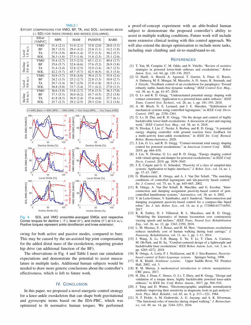
TABLE IEFFORT COMPARISONS FOR VMO, BF, TA, AND SOL: SHOWING MEAN
(± SD) FOR TASKS (ROWS) AND MODES (COLUMNS).Effort MPE HAM PASSIVE BARE
[%MVC]
Lev
el1.
0m/s
VMO 31.4 (2.1) 31.0 (2.1) 33.8 (2.0) 28.0 (3.3)BF 28.7 (3.5) 29.4 (4.2) 23.8 (3.1) 14.2 (1.9)TA 37.9 (3.9) 40.9 (1.4) 37.5 (1.5) 30.2 (5.7)
SOL 26.3 (1.8) 27.5 (1.8) 31.8 (2.5) 25.1 (2.0)
Dec
line
0.6
m/s
VMO 35.4 (2.7) 33.3 (2.5) 43.1 (2.1) 49.4 (3.7)BF 35.6 (5.7) 32.6 (6.6) 37.6 (5.2) 26.9 (3.8)TA 31.4 (3.4) 32.8 (2.5) 32.9 (3.4) 18.7 (2.5)
SOL 42.2 (5.7) 45.7 (5.7) 42.5 (6.5) 41.3 (3.4)
Lev
el0.
6m/s
VMO 34.9 (3.7) 35.8 (4.0) 39.4 (3.3) 35.9 (2.4)BF 24.2 (1.5) 25.2 (2.7) 22.8 (3.3) 10.9 (2.7)TA 29.7 (3.4) 30.7 (2.9) 27.0 (1.8) 18.5 (3.1)
SOL 36.8 (5.0) 33.7 (3.4) 37.1 (4.2) 27.0 (3.3)
Incl
ine
0.6
m/s
VMO 36.6 (3.9) 33.8 (2.7) 37.6 (3.3) 36.3 (7.0)BF 37.3 (5.3) 36.0 (6.2) 43.7 (4.5) 25.2 (3.8)TA 41.8 (8.3) 36.9 (2.4) 37.6 (4.0) 27.7 (6.1)
SOL 25.7 (2.3) 29.2 (2.5) 29.3 (2.6) 31.2 (3.6)
Fig. 4. SOL and VMO ensemble-averaged EMGs and respectiveComex torques for decline (−5◦), level (0◦), and incline (5◦) at 0.6 m/s.Positive torques represent ankle dorsiflexion and knee extension.
swing for both active and passive modes, compared to bare.This may be caused by the un-assisted hip joint compensatingfor the added distal mass of the exoskeleton, requiring greaterhip drive (an additional function of the BF).
The observations in Fig. 4 and Table I meet our simulationexpectations and demonstrate the potential to assist muscu-lature in multiple tasks. Additional human subjects would beneeded to draw more generic conclusions about the controller’seffectiveness, which is left to future work.
IV. CONCLUSION
In this paper, we proposed a novel energetic control strategyfor a knee-ankle exoskeleton that can shape both gravitationaland gyroscopic terms based on the IDA-PBC, which wasoptimized to fit normative human torques. We performed
a proof-of-concept experiment with an able-bodied humansubject to demonstrate the proposed controller’s ability toassist in multiple walking conditions. Future work will includemore extensive clinical testing with this control approach. Wewill also extend the design optimization to include more tasks,including stair climbing and sit-to-stand/stand-to-sit.
REFERENCES
[1] T. Yan, M. Cempini, C. M. Oddo, and N. Vitiello, “Review of assistivestrategies in powered lower-limb orthoses and exoskeletons,” Robot.Auton. Syst., vol. 64, pp. 120–136, 2015.
[2] O. Harib, A. Hereid, A. Agrawal, T. Gurriet, S. Finet, G. Boeris,A. Duburcq, M. E. Mungai, M. Masselin, A. D. Ames, K. Sreenath, andJ. Grizzle, “Feedback control of an exoskeleton for paraplegics: Towardrobustly stable, hands-free dynamic walking,” IEEE Control Syst. Mag.,vol. 38, no. 6, pp. 61–87, 2018.
[3] G. Lv and R. D. Gregg, “Underactuated potential energy shaping withcontact constraints: Application to a powered knee-ankle orthosis,” IEEETrans. Control Syst. Technol., vol. 26, no. 1, pp. 181–193, 2018.
[4] A. M. Bloch, N. E. Leonard, and J. E. Marsden, “Stabilization ofmechanical systems using controlled lagrangians,” in IEEE Conf. Decis.Control, 1997, pp. 2356–2361.
[5] G. Lv, H. Zhu, and R. D. Gregg, “On the design and control of highlybackdrivable lower-limb exoskeletons: A discussion of past and ongoingwork,” IEEE Control Syst. Mag., vol. 38, no. 6, 2018.
[6] N. Divekar, J. Lin, C. Nesler, S. Borboa, and R. D. Gregg, “A potentialenergy shaping controller with ground reaction force feedback fora multi-activity knee-ankle exoskeleton,” in IEEE Int. Conf. Biomed.Robot. Biomechatronics, 2020.
[7] J. Lin, G. Lv, and R. D. Gregg, “Contact-invariant total energy shapingcontrol for powered exoskeletons,” in American Control Conf. IEEE,2019, pp. 664–670.
[8] J. Lin, N. Divekar, G. Lv, and R. D. Gregg, “Energy shaping controlwith virtual spring and damper for powered exoskeletons,” in IEEE Conf.Decis. Control, 2019, pp. 3039–3045.
[9] J. E. Colgate and G. G. Schenkel, “Passivity of a class of sampled-datasystems: Application to haptic interfaces,” J. Robot. Syst., vol. 14, no. 1,pp. 37–47, 1997.
[10] G. Blankenstein, R. Ortega, and A. J. Van Der Schaft, “The matchingconditions of controlled lagrangians and ida-passivity based control,”Int. J. Control, vol. 75, no. 9, pp. 645–665, 2002.
[11] R. Ortega, A. Van Der Schaft, B. Maschke, and G. Escobar, “Inter-connection and damping assignment passivity-based control of port-controlled hamiltonian systems,” Automatica, vol. 38, no. 4, 2002.
[12] V. de Leon-Gomez, V. Santibanez, and J. Sandoval, “Interconnection anddamping assignment passivity-based control for a compass-like bipedrobot,” Int. J. Adv. Robot. Syst., vol. 14, no. 4, p. 1729881417716593,2017.
[13] K. R. Embry, D. J. Villarreal, R. L. Macaluso, and R. D. Gregg,“Modeling the kinematics of human locomotion over continuouslyvarying speeds and inclines,” IEEE Trans. Neural Syst. RehabilitationEng., vol. 26, no. 12, pp. 2342–2350, 2018.
[14] L. M. Mooney, E. J. Rouse, and H. M. Herr, “Autonomous exoskeletonreduces metabolic cost of human walking during load carriage,” J.Neuroeng. Rehabilitation, vol. 11, no. 1, pp. 1–11, 2014.
[15] J. Wang, X. Li, T.-H. Huang, S. Yu, Y. Li, T. Chen, A. Carriero,M. Oh-Park, and H. Su, “Comfort-centered design of a lightweight andbackdrivable knee exoskeleton,” IEEE Robot. Autom. Lett., vol. 3, no. 4,pp. 4265–4272, 2018.
[16] R. Ortega, A. Lorıa, P. J. Nicklasson, and H. J. Sira-Ramirez, Passivity-based control of Euler-Lagrange systems. Springer-Verlag, 1998.
[17] H. K. Khalil, Nonlinear systems. Upper Saddle River, NJ: PrenticeHall, 2002, vol. 3.
[18] R. M. Murray, A mathematical introduction to robotic manipulation.CRC press, 2017.
[19] H. Zhu, J. Doan, C. Stence, G. Lv, T. Elery, and R. Gregg, “Design andvalidation of a torque dense, highly backdrivable powered knee-ankleorthosis,” in IEEE Int. Conf. Robot. Autom., 2017, pp. 504–510.
[20] J. Yang and D. Winter, “Electromyographic amplitude normalizationmethods: improving their sensitivity as diagnostic tools in gait analysis,”Arch. Phys. Med. Rehabil., vol. 65, no. 9, p. 517—521, 1984.
[21] N. T. Pickle, A. M. Grabowski, A. G. Auyang, and A. K. Silverman,“The functional roles of muscles during sloped walking,” J. Biomechan-ics, vol. 49, no. 14, pp. 3244–3251, 2016.