Embed Size (px)
Citation preview

OPTIMAL HANDLING AND FAULT-TOLERANT
SPEED REGULATION OF HEAVY HAUL TRAINS
by
Xiangtao Zhuan
Submitted in partial fulfilment of the requirements for the degree
Philosophae Doctoral (Electronic Engineering)
in the Faculty of
Engineering, Built Environment and Information Technology
University of Pretoria, Pretoria
October, 2006
UUnniivveerrssiittyy ooff PPrreettoorriiaa eettdd –– ZZhhuuaann,, XX ((22000077))

Optimal Handling and Fault-tolerant SpeedRegulation of Heavy Haul Trains
by
Xiangtao Zhuan
Promotor: Prof. Xiaohua Xia
Department: Electrical, Electronic and Computer Engineering
Faculty of Engineering, Built Environment and Information Technology
Degree: PhD (Electronic Engineering)
Keywords: output regulation, measurement feedback, nonlinear system, train con-
trol, ECP braking system, distributed power control, optimal control, LQR, FDI, FTC
Summary
Heavy haul trains are used to transport mineral resources from inland mines toharbours in South Africa. It is believed that the cost is less with a larger load percar or per train. This has resulted in the use of long heavy haul trains. The increasein train length has posed unprecedented technical challenges. For heavy haul trains,energy consumption, running time and in-train forces between neighbouring cars areof much concern to transportation corporations.
The objective of the study is to find optimal driving methodologies for the im-plementation of a desired speed profile with energy consumption and in-train forcesconsidered.
Firstly, three control strategies are proposed in this study for train handling. Inview of the characteristics of traditional pneumatic braking systems and the new Elec-tronically Controlled Pneumatic (ECP) braking systems, a simulation study of optimalopen loop controllers was undertaken. The result shows that the ECP braking systemsdemonstrate superb performance compared with pneumatic braking systems, especiallytogether with independent distributed power (iDP) control.
Thus, the main focus of the study was the control of heavy haul trains equipped with
i
UUnniivveerrssiittyy ooff PPrreettoorriiaa eettdd –– ZZhhuuaann,, XX ((22000077))

ECP braking systems. It is shown that there are redundancies in designing an open loopcontroller. An optimization procedure is applied to schedule cruise control by taking thein-train forces into initial design consideration. Optimal open loop scheduling presentsa better starting point for a closed-loop controller design. A type of linear quadraticregulator (LQR) controller with state feedback is simulated to verify the above result.
However, the closed-loop control law is designed based on full state feedback, whichis not practical since not all the states can be measured.
An observer could be designed to supplement the LQR controller if partial statesare measured. This is, however, not the approach taken in this study. Instead, theapplication of output regulation of nonlinear systems with measured output feedbackto the control of heavy haul trains is considered. This approach to design is practicallyfeasible and manageable, and by its nature, is also easily integrable with human drivers.In this study, the existing result of output regulation of nonlinear systems is extended.The output regulation problem of nonlinear systems with measured output feedbackis formulated in this study and solved for the local version and global version. Forits application to train control, some application issues are discussed. Based on theproposed theory, a speed regulator for train control is designed. Simulation resultsshow its applicability.
Lastly, this study concentrates on the fault-tolerant capacity of the speed regula-tor. Two kinds of fault modes are considered. Fault detection and isolation for thesensor fault and braking system fault are exploited. Controller redesign is also given.Simulation results show that such a speed regulator has a fault-tolerant capacity to thecorresponding faults.
ii
UUnniivveerrssiittyy ooff PPrreettoorriiaa eettdd –– ZZhhuuaann,, XX ((22000077))

Acknowledgement
No words could express my feeling about the past years I have spent on my doctoralstudy at the University of Pretoria. It is there I met Professor Xiaohua Xia, whohas had and will continue to have a significant impact on my life. He is not just aprofessional advisor, but also a good friend. His ideas and points of view have been aconstant source of inspiration, and our endless discussions have taught me to be moreinquisitive. From him, I have also learned how to enjoy the job and living. I would liketo express my deepest gratitude to him for his support, encouragement and guidance.Thanks for widening my views and helping me achieving my goals.
I would also like to thank all the members in the train project at the University ofPretoria. They are Mingshan Chou, Jerry Wang, Herry Mizero and Martin Strempel.Their excellent work contributes much to my study. The discussions among us give mea lot of inspiration.
I am very grateful to my former advisor, Professor Guilin Zheng at Wuhan Uni-versity, China during my master’s study. His moral support and advice give me muchencouragement and motivation.
Thanks to all the friends I met here in Pretoria: Dr. G. Ma, Miss Y. Li, Mr. M.Chen, Mr. D. Wei, Dr. J. Zhang and many others. In particular, I want to mentionMr. Xiyin Liang in our control group, who gives me a lot of help in my study. Theirmoral support has helped me in difficult moments: from them I learned a great deal.
I am in debt to my family in China, my parents and my sister. It has been hard tospend this time far from them, but the distance strengthens our connection even more.I would like to thank my beloved wife, Qi Li, for her love, patience and encouragement,and our little son, Yi Zhuan. To them and their smiles I owe everything I attained.
iii
UUnniivveerrssiittyy ooff PPrreettoorriiaa eettdd –– ZZhhuuaann,, XX ((22000077))

Publications
The following list contains publications that are based on the work presented in thethesis.
X. Zhuan and X. Xia, “Cruise control scheduling of heavy haul trains,” IEEETransactions on Control System Technology, Vol. 14, No. 4, 2006, pp. 757–766.
X. Zhuan and X. Xia, “Optimal scheduling and control of heavy haul trains equip-ped with electronically controlled pneumatic braking systems,” IEEE Transactions onControl System Technology, 2006 (accepted).
X. Zhuan and X. Xia, “Speed regulation with measured output feedback in thecontrol of heavy haul trains,” Automatica, 2006 (submitted).
X. Zhuan and X. Xia, “Output regulation of nonlinear systems by using measure-ment feedback,” IEEE Transactions on Automatic Control, 2006 (submitted).
X. Xia and X. Zhuan, “Model-based handling of ECP heavy haul trains,” SA Jour-nal of Science, 2005 (accepted).
X. Zhuan and X. Xia, “Optimal scheduling and control of heavy haul trains equip-ped with electronically controlled pneumatic braking systems,” Proceedings of the 6thWorld Congress on Intelligent Control and Automation, 21–23 June, 2006, Dalian,China, pp. 8168–8172.
X. Zhuan and X. Xia, “Output regulation of nonlinear systems in the form ofmeasured output feedback,” Proceedings of South African Control Conference, July2006, Durban, South Africa, pp. 33–38.
X. Zhuan and X. Xia, “Speed regulation with measurement feedback of heavy haultrains,” Proceedings of the 4th IFAC–Symposium on Mechatronic Systems, 12–14 Sep-tember 2006, Heidelberg, Germany, pp. 794–798.
iv
UUnniivveerrssiittyy ooff PPrreettoorriiaa eettdd –– ZZhhuuaann,, XX ((22000077))

Contents
1 Introduction 1
1.1 Background . . . . . . . . . . . . . . . . . . . . . . . . . . . . . . . . . 1
1.2 Literature review of train handling . . . . . . . . . . . . . . . . . . . . 3
1.3 Motivation . . . . . . . . . . . . . . . . . . . . . . . . . . . . . . . . . . 7
1.4 Contributions of thesis . . . . . . . . . . . . . . . . . . . . . . . . . . . 8
1.5 Layout of thesis . . . . . . . . . . . . . . . . . . . . . . . . . . . . . . . 8
2 Train model 10
2.1 Introduction . . . . . . . . . . . . . . . . . . . . . . . . . . . . . . . . . 10
2.2 Cascade mass-point model . . . . . . . . . . . . . . . . . . . . . . . . . 10
2.2.1 Car model . . . . . . . . . . . . . . . . . . . . . . . . . . . . . . 11
2.2.2 Coupler model . . . . . . . . . . . . . . . . . . . . . . . . . . . 12
2.2.3 Train model of a cascade of mass points . . . . . . . . . . . . . 12
2.2.4 Input constraint . . . . . . . . . . . . . . . . . . . . . . . . . . . 13
2.2.5 In-train force constraints . . . . . . . . . . . . . . . . . . . . . . 14
2.3 Stop distance calculation – a model-comparison . . . . . . . . . . . . . 14
2.3.1 Information on the collision . . . . . . . . . . . . . . . . . . . . 14
2.3.2 Calculation of stop distance . . . . . . . . . . . . . . . . . . . . 15
v
UUnniivveerrssiittyy ooff PPrreettoorriiaa eettdd –– ZZhhuuaann,, XX ((22000077))

2.3.3 Simple model . . . . . . . . . . . . . . . . . . . . . . . . . . . . 17
2.3.4 Cascade mass-point model . . . . . . . . . . . . . . . . . . . . . 20
2.3.5 Conclusions of the calculation . . . . . . . . . . . . . . . . . . . 22
2.4 Conclusion . . . . . . . . . . . . . . . . . . . . . . . . . . . . . . . . . . 23
3 Optimal scheduling 24
3.1 Introduction . . . . . . . . . . . . . . . . . . . . . . . . . . . . . . . . . 24
3.2 Control strategies . . . . . . . . . . . . . . . . . . . . . . . . . . . . . . 25
3.3 Optimal scheduling on trains equipped with different braking systems . 26
3.3.1 Formulation of the optimal problem . . . . . . . . . . . . . . . . 26
3.3.2 Optimization algorithm . . . . . . . . . . . . . . . . . . . . . . . 29
3.3.3 Simulation of different braking systems . . . . . . . . . . . . . . 31
3.4 Scheduling . . . . . . . . . . . . . . . . . . . . . . . . . . . . . . . . . . 37
3.4.1 Heuristic scheduling . . . . . . . . . . . . . . . . . . . . . . . . 38
3.4.2 Optimal scheduling . . . . . . . . . . . . . . . . . . . . . . . . . 38
3.4.3 Simulation of heuristic scheduling vs. optimal scheduling . . . . 39
3.5 LQR controller . . . . . . . . . . . . . . . . . . . . . . . . . . . . . . . 43
3.5.1 LQR closed-loop controller . . . . . . . . . . . . . . . . . . . . . 43
3.5.2 Anti-windup technique . . . . . . . . . . . . . . . . . . . . . . . 44
3.5.3 Simulation settings of LQR controllers . . . . . . . . . . . . . . 45
3.5.4 Simulation results of LQR controllers . . . . . . . . . . . . . . . 46
3.6 Conclusion . . . . . . . . . . . . . . . . . . . . . . . . . . . . . . . . . . 52
4 Speed regulation 53
vi
UUnniivveerrssiittyy ooff PPrreettoorriiaa eettdd –– ZZhhuuaann,, XX ((22000077))

4.1 Introduction . . . . . . . . . . . . . . . . . . . . . . . . . . . . . . . . . 53
4.2 Output regulation with measured output feedback . . . . . . . . . . . . 53
4.2.1 Problem formulation and preliminaries . . . . . . . . . . . . . . 55
4.2.2 Assumptions . . . . . . . . . . . . . . . . . . . . . . . . . . . . . 59
4.2.3 Solution of the global DMFORP . . . . . . . . . . . . . . . . . . 62
4.2.4 Solution of the local DMFORP . . . . . . . . . . . . . . . . . . 66
4.2.5 Examples . . . . . . . . . . . . . . . . . . . . . . . . . . . . . . 71
4.3 Speed regulation . . . . . . . . . . . . . . . . . . . . . . . . . . . . . . 75
4.3.1 Application of output regulation in heavy haul trains . . . . . . 76
4.3.2 Trajectory design of heavy haul trains . . . . . . . . . . . . . . 79
4.3.3 Speed regulation controller design . . . . . . . . . . . . . . . . . 79
4.3.4 Simulation of speed regulation . . . . . . . . . . . . . . . . . . . 81
4.4 Conclusion . . . . . . . . . . . . . . . . . . . . . . . . . . . . . . . . . . 85
5 Fault-tolerant control 87
5.1 Introduction . . . . . . . . . . . . . . . . . . . . . . . . . . . . . . . . . 87
5.2 Fault detectability . . . . . . . . . . . . . . . . . . . . . . . . . . . . . 89
5.3 Fault modes of trains . . . . . . . . . . . . . . . . . . . . . . . . . . . . 93
5.3.1 Speed sensor faults . . . . . . . . . . . . . . . . . . . . . . . . . 94
5.3.2 Actuator faults . . . . . . . . . . . . . . . . . . . . . . . . . . . 95
5.4 Fault detection and isolation . . . . . . . . . . . . . . . . . . . . . . . . 95
5.4.1 Sensor fault detection and isolation . . . . . . . . . . . . . . . . 95
5.4.2 Actuator fault detection and isolation . . . . . . . . . . . . . . . 98
5.5 Fault-tolerant control (FTC) . . . . . . . . . . . . . . . . . . . . . . . . 104
vii
UUnniivveerrssiittyy ooff PPrreettoorriiaa eettdd –– ZZhhuuaann,, XX ((22000077))

5.5.1 FDI and FTC in the case of sensor faults . . . . . . . . . . . . . 104
5.5.2 Controller redesign in the case of a locomotive fault . . . . . . . 105
5.5.3 FDI and FTC in the case of a wagon fault . . . . . . . . . . . . 107
5.6 Simulation . . . . . . . . . . . . . . . . . . . . . . . . . . . . . . . . . . 107
5.6.1 Simulation of sensor faults . . . . . . . . . . . . . . . . . . . . . 107
5.6.2 Simulation of locomotive faults . . . . . . . . . . . . . . . . . . 114
5.6.3 Simulation of wagon faults . . . . . . . . . . . . . . . . . . . . . 122
5.7 Conclusion . . . . . . . . . . . . . . . . . . . . . . . . . . . . . . . . . . 127
6 Conclusions 129
6.1 Summary . . . . . . . . . . . . . . . . . . . . . . . . . . . . . . . . . . 129
6.2 Assessment . . . . . . . . . . . . . . . . . . . . . . . . . . . . . . . . . 130
6.3 Future work . . . . . . . . . . . . . . . . . . . . . . . . . . . . . . . . . 131
viii
UUnniivveerrssiittyy ooff PPrreettoorriiaa eettdd –– ZZhhuuaann,, XX ((22000077))

List of Figures
1.1 A heavy haul train of Spoornet, South Africa . . . . . . . . . . . . . . 3
1.2 Train handling . . . . . . . . . . . . . . . . . . . . . . . . . . . . . . . 4
1.3 Irrational power distribution . . . . . . . . . . . . . . . . . . . . . . . . 6
2.1 Longitudinal model of car . . . . . . . . . . . . . . . . . . . . . . . . . 11
2.2 Longitudinal model of coupler . . . . . . . . . . . . . . . . . . . . . . . 12
2.3 Coupler force vs. displacement . . . . . . . . . . . . . . . . . . . . . . . 12
2.4 Longitudinal model of train . . . . . . . . . . . . . . . . . . . . . . . . 13
2.5 Locomotive group effort vs. notch and velocity . . . . . . . . . . . . . . 14
3.1 Track profile . . . . . . . . . . . . . . . . . . . . . . . . . . . . . . . . . 33
3.2 1-1 strategy without ECP . . . . . . . . . . . . . . . . . . . . . . . . . 33
3.3 2-1 strategy without ECP . . . . . . . . . . . . . . . . . . . . . . . . . 34
3.4 1-1 strategy with ECP . . . . . . . . . . . . . . . . . . . . . . . . . . . 34
3.5 2-1 strategy with ECP . . . . . . . . . . . . . . . . . . . . . . . . . . . 35
3.6 2-2 strategy with ECP/iDP . . . . . . . . . . . . . . . . . . . . . . . . 35
3.7 Heuristic scheduling . . . . . . . . . . . . . . . . . . . . . . . . . . . . . 40
3.8 1-1 strategy optimal scheduling . . . . . . . . . . . . . . . . . . . . . . 41
3.9 2-1 strategy optimal scheduling . . . . . . . . . . . . . . . . . . . . . . 41
138
UUnniivveerrssiittyy ooff PPrreettoorriiaa eettdd –– ZZhhuuaann,, XX ((22000077))

3.10 2-2 strategy optimal scheduling . . . . . . . . . . . . . . . . . . . . . . 42
3.11 1-1 strategy closed-loop control based on heuristic scheduling . . . . . . 46
3.12 2-1 strategy closed-loop control based on heuristic scheduling . . . . . . 47
3.13 2-2 strategy closed-loop control based on heuristic scheduling . . . . . . 47
3.14 1-1 strategy closed-loop control based on optimal scheduling . . . . . . 48
3.15 2-1 strategy closed-loop control based on optimal scheduling . . . . . . 48
3.16 2-2 strategy closed-loop control based on optimal scheduling . . . . . . 49
4.1 Modified speed profile . . . . . . . . . . . . . . . . . . . . . . . . . . . 80
4.2 Output regulation with measurement feedback . . . . . . . . . . . . . . 82
4.3 A longer track profile . . . . . . . . . . . . . . . . . . . . . . . . . . . . 84
4.4 Speed regulation on a longer track profile . . . . . . . . . . . . . . . . . 84
5.1 Sensor fault detection and isolation programme . . . . . . . . . . . . . 106
5.2 Wagon fault detection and isolation programme . . . . . . . . . . . . . 108
5.3 Non-FTC (sensor accuracy of 100%) . . . . . . . . . . . . . . . . . . . 109
5.4 Non-FTC (sensor accuracy of 1 ± 5%) . . . . . . . . . . . . . . . . . . 110
5.5 FTC (sensor accuracy of 100%) . . . . . . . . . . . . . . . . . . . . . . 110
5.6 FTC (sensor accuracy of 1 ± 5%) . . . . . . . . . . . . . . . . . . . . . 111
5.7 FTC (sensor accuracy of 1 + 0% and second sensor gain fault of +5% ) 112
5.8 FTC (sensor accuracy of 1 ± 5% and second sensor gain fault of +5%) . 112
5.9 Non-FTC (sensor accuracy of 1 ± 5% and 2nd sensor gain fault of +5%) 113
5.10 FTC (third sensor with a gain fault of +7%) . . . . . . . . . . . . . . . 115
5.11 FTC (fourth sensor with a gain fault of −20%) . . . . . . . . . . . . . 115
UUnniivveerrssiittyy ooff PPrreettoorriiaa eettdd –– ZZhhuuaann,, XX ((22000077))

5.12 FTC (fourth sensor with a gain fault of +20%) . . . . . . . . . . . . . . 116
5.13 FTC (concurrent faults) . . . . . . . . . . . . . . . . . . . . . . . . . . 116
5.14 FTC (concurrent faults) . . . . . . . . . . . . . . . . . . . . . . . . . . 117
5.15 Front-loco-fault with an FTC . . . . . . . . . . . . . . . . . . . . . . . 119
5.16 Front-loco-fault with a non-FTC . . . . . . . . . . . . . . . . . . . . . . 119
5.17 Rear-loco-fault with an FTC . . . . . . . . . . . . . . . . . . . . . . . . 120
5.18 Rear-loco-fault with a non-FTC . . . . . . . . . . . . . . . . . . . . . . 120
5.19 Both-loco-fault with an FTC . . . . . . . . . . . . . . . . . . . . . . . . 121
5.20 Both-loco-fault with a non-FTC . . . . . . . . . . . . . . . . . . . . . . 121
5.21 Faultless train with an FTC of braking system . . . . . . . . . . . . . . 123
5.22 Small fault in an FTC of braking system . . . . . . . . . . . . . . . . . 123
5.23 Small fault in a non-FTC . . . . . . . . . . . . . . . . . . . . . . . . . 124
5.24 Big fault in an FTC of braking system . . . . . . . . . . . . . . . . . . 124
5.25 Big fault in a non-FTC . . . . . . . . . . . . . . . . . . . . . . . . . . . 125
5.26 Partial fault in an FTC of braking system . . . . . . . . . . . . . . . . 125
5.27 Partial fault in a non-FTC . . . . . . . . . . . . . . . . . . . . . . . . . 126
UUnniivveerrssiittyy ooff PPrreettoorriiaa eettdd –– ZZhhuuaann,, XX ((22000077))

List of Tables
2.1 Wagon types and parameters . . . . . . . . . . . . . . . . . . . . . . . 17
2.2 Wagon type CCL1&3 . . . . . . . . . . . . . . . . . . . . . . . . . . . . 20
2.3 Wagon type CCL2(CCR2) . . . . . . . . . . . . . . . . . . . . . . . . . 21
2.4 Wagon type CCL5–9(CCR5–9) . . . . . . . . . . . . . . . . . . . . . . 21
2.5 Wagon type CCR1&3 . . . . . . . . . . . . . . . . . . . . . . . . . . . . 21
3.1 Acceleration profile . . . . . . . . . . . . . . . . . . . . . . . . . . . . . 27
3.2 Locomotive group parameters . . . . . . . . . . . . . . . . . . . . . . . 32
3.3 Wagon group parameters . . . . . . . . . . . . . . . . . . . . . . . . . . 32
3.4 Comparison of braking systems: pneumatics vs. ECP . . . . . . . . . . 36
3.5 Comparison of optimal scheduling vs. heuristic scheduling . . . . . . . 42
3.6 Performance with Ke = 1, Kf = 1, Kv = 1 . . . . . . . . . . . . . . . . 50
3.7 Performance with Ke = 1, Kf = 1, Kv = 10 . . . . . . . . . . . . . . . . 50
3.8 Performance with Ke = 1, Kf = 10, Kv = 1 . . . . . . . . . . . . . . . . 51
3.9 Performance with Ke = 100, Kf = 1, Kv = 1 . . . . . . . . . . . . . . . 51
4.1 Performance comparison . . . . . . . . . . . . . . . . . . . . . . . . . . 83
5.1 Comparison of non-FTC and FTC of sensor faults . . . . . . . . . . . . 117
141
UUnniivveerrssiittyy ooff PPrreettoorriiaa eettdd –– ZZhhuuaann,, XX ((22000077))

5.2 Comparison of non-FTC and FTC of locomotive faults . . . . . . . . . 122
5.3 Comparison of non-FTC and FTC of wagon faults . . . . . . . . . . . . 126
UUnniivveerrssiittyy ooff PPrreettoorriiaa eettdd –– ZZhhuuaann,, XX ((22000077))

Chapter 1
Introduction
1.1 Background
The railway is believed to be the most economical among all transportation means,especially for the transportation of mineral resources. In South Africa, most minesare situated inland, so heavy haul trains are required to transport these resources toharbours. It is presumed that the cost is less with a larger quantity of load per car orper train in terms of the schedule and the number of people involved. This has resultedin the use of long trains with multi-locomotives.
Traditionally, the operation of such multi-locomotive trains with pneumatic brakingsystems is in essence a simple one. The brake control signal is transmitted throughoutthe train wagons, which results in the same effort command of all the wagons. All thelocomotives also have to make the same efforts, for the remote locomotives (groups) areoperated in tandem with the leading one. In this operation there are only two controlsignals, one for locomotives, and the other for wagons. There are two prominentdrawbacks with such an operation method.
1) The locomotives are distributed, but the power is not distributed independently.
2) The wagons’ braking system is pneumatic and the braking control signal is prop-agated to each wagon through the air pressure change along the air pipe runningthroughout the train, which leads to different time delays in braking the wagons.
These drawbacks result in slow running speed, the possibility of derailment and alimit on the train length.
The first disadvantage is eliminated through the employment of the (independent)distributed power (DP, iDP) traction operation, in which the traction powers of the
1
UUnniivveerrssiittyy ooff PPrreettoorriiaa eettdd –– ZZhhuuaann,, XX ((22000077))

Chapter 1 Introduction
locomotives are different.
The second one was also provisionally solved with the application of new technologyin the 1990s. To improve the train performance (the second of the above disadvan-tages), the Association of American Railroads developed a new braking system – theElectronically Controlled Pneumatic (ECP) braking system, in which the brake com-mand signals are electronic and are received by all the wagons simultaneously althoughpneumatics are still used to supply the brake power. Spoornet, one of the train op-erators in South Africa, is the first railway in the world to roll out the ECP brakingsystem (on its COALink line) on a large scale. The introduction of ECP brakingsystems can be seen in [1, 2]. Operational advantages follow the application of ECPbraking systems [1].
1) Wheel and brake shoe wear can be reduced with an appropriate distribution ofbraking and pressure control;
2) Energy-efficient operation can be reached with the use of graduated release ca-pability to eliminate power braking;
3) The safety level can be increased with the accurate control of the whole train anddecreased stopping distance;
4) The in-train forces can be reduced owing to the complete brake control of everycar of the train.
At present, such a heavy haul train in South Africa is composed of about 200wagons and it is about 2.5 km long. A train running on the COALink line of Spoornetis shown in Fig. 1.1. It is exactly because of the above advantages that extremelylong trains (up to 10 km in length) are considered in the business plan of Spoornet ofSouth Africa on its COALink. This increase in train length has posed unprecedentedtechnical challenges.
According to [3], train handling includes the start phase of the train, the speedmaintenance phase, and the stop phase of the train. Since the railway track is longand the train is running in the speed maintenance phase during most of the runningtime, the train scheduling of the speed maintenance phase is the focus of this study.In realizing optimal management of in-train forces, it is justifiable to assume that asteady state of train motion is reached and held. In this study, the term “scheduling” isborrowed from the railway industry for train operation and handling, where it refers tothe decision of a driving sequence in terms on locomotives’ power notches and wagons’braking pressure along a specific railway track. In the context of control systems, this“scheduling” activity is interpreted as an open loop control design, which brings thetrain to an expected motion trajectory.
For heavy haul trains, energy consumption, running time and in-train forces be-tween the neighbouring cars are of much concern to transportation corporations. The
Electrical, Electronic and Computer Engineering 2
UUnniivveerrssiittyy ooff PPrreettoorriiaa eettdd –– ZZhhuuaann,, XX ((22000077))

Chapter 1 Introduction
Figure 1.1: A heavy haul train of Spoornet, South Africa
energy consumption is related to the direct economic profit while the running timedetermines the quality of the service. In-train force control contributes to the saferunning of the train and to limiting maintenance cost. The larger the in-train force is,the higher the maintenance cost. For long trains, this is even more important. It isalso more difficult to control the in-train forces of a long heavy haul train. It is noticedthat the in-train forces depend both on the driving speed and on the power/brakedistribution along the train. This is why the independent Distributed Power (iDP)operation and ECP braking systems have been introduced into practice.
1.2 Literature review of train handling
A frame for train handling is shown in Fig. 1.2. In train handling, various studies havetried to achieve different objectives.
For energy consumption, some studies have been done in [4, 5, 6, 7, 8, 9] for a trainto travel from one station to the next one in a given time. In most of these papers,the locomotives are supposed to have three discrete control settings: power, coast and
Electrical, Electronic and Computer Engineering 3
UUnniivveerrssiittyy ooff PPrreettoorriiaa eettdd –– ZZhhuuaann,, XX ((22000077))

Chapter 1 Introduction
Figure 1.2: Train handling
brake. A finite sequence of the locomotive settings is arbitrarily predetermined andthen the optimal algorithms are to determine the switching points where the controlsetting changes. Recently, an analytical approach has been proposed in [10] to findthe control switching point. A train is modelled as a mass point in these papers. It isshown in [6] that a train with distributed mass can be treated as a point mass withactual gradient profile replaced by an effective gradient acceleration. In these papers,the dynamics within a train are ignored and speed tracking and in-train forces are notinvestigated.
The other models a train as a cascade of mass points connected with couplers, forexample in [11, 12, 13, 14, 15]. This model is more accurate than a mass-point modelfor a train 2.5 km long. In these papers, a desired speed profile along a given trackis assumed first. The subject of the studies is to design controllers to maintain thedesired speed with some objectives considered.
For high speed (passenger) trains, speed tracking is the most important. Thestudies can be seen in [12, 13, 14]. In [12] [13], the H2/H∞ method with full statefeedback is employed to deal with the cruising of high speed trains. The objective isto maintain the train speed as expected. Cruise control is proposed for two types ofhigh speed trains, distributed driving with each car having its own driving force, andpush-pull driving only with driving forces at the first and the last car. A calculationmethod to determine equilibrium point for distributed driving is given. Even thoughthe push-pull driving is also taken as a way to operate heavy haul trains, again, thispaper does not present optimal scheduling of equilibrium points. In [14], similar to [12],different input/output decoupling problems for high speed trains are studied. To getthe equilibrium point, it is assumed that one of the in-train forces is zero or the drivingforce is equally distributed to the locomotives. This assumption leads to a heuristic
Electrical, Electronic and Computer Engineering 4
UUnniivveerrssiittyy ooff PPrreettoorriiaa eettdd –– ZZhhuuaann,, XX ((22000077))

Chapter 1 Introduction
trim point. In these papers, a train is considered as a cascade of mass points connectedwith nonlinear couplers. This model can be used to study the dynamics within atrain. However, the in-train forces are not emphasized in these papers because theyare not particularly important for such short trains. Without ECP technology, theapplication of these control approaches to heavy haul trains is hindered by the controlsignal transmission delay.
An early study of in-train forces can be seen in [11], where an LQR optimal algo-rithm is employed to minimize the coupler forces and/or velocity deviations from thereference values. It is assumed that at the nominal point, the nominal input vectorconsisting of throttling and braking forces to maintain the nominal speed, is equal tothe sum of the resistance and gravity forces. Then a linearized model is used to calcu-late the control law. Considering the large number and the constraints of the variables,the train model is simplified. This paper offers an excellent setup to deal with the in-train forces and various calculations of optimal closed-loop control. While closed-loopcontrol is used to optimize the interplay between in-train forces and speed holding,the scheduling of the desired holding speed is typically determined through an openloop controller design. It is noted, however, that the off-line open loop scheduling in[11] is a rather heuristic one, without making optimal use of the control redundancies.The closed-loop control is designed based on full state feedback, and with two crudeassumptions for the insufficiency of the measurement of the states, the closed-loop con-troller is simplified to full speed feedback. Even for speed, it replaces all cars’ speedswith the limited number of locomotives’ speeds.
It is quite interesting to note that the early study of [11] takes into considerationsome practical aspects of ECP and iDP even though the ECP/iDP technology is notimplemented in practice on a visible scale. However, the model in this paper is largelysimplified by taking variations due to track slope and curvature changes as modeldisturbances. New technologies, such as the Global Position System (GPS), make theinformation readily available.
In [15] and [16], based on a cascade point mass model, which is validated in [17]with the operational data from Spoornet, an LQR approach is employed to optimizethe in-train forces, energy consumption and velocity tracking of a heavy haul trainequipped with an ECP braking system. Considering the constraints of control inputchannel number, a concept of fencing is proposed. In off-line scheduling, the equilibriaare calculated under the assumption that the driving force is equally distributed tothe locomotives while all the braking forces of wagons are zeros and the braking forceis equally distributed to the locomotives and wagons. This open loop scheduling isheuristic, too. With the discrete quantities of the locomotives’ efforts considered, theefforts of the locomotives are almost always equal.
In [18], flatness-based methods in [19] are used to design the open loop controlschemes for a heavy haul train, where a train is taken as an infinite dimensional linearmodel.
Electrical, Electronic and Computer Engineering 5
UUnniivveerrssiittyy ooff PPrreettoorriiaa eettdd –– ZZhhuuaann,, XX ((22000077))

Chapter 1 Introduction
The off-line scheduling for the equilibria in the above papers is based on someheuristic assumptions without considering the optimization of the equilibrium. Thedifference among the different equilibria is of course not discussed.
The heuristic scheduling way may lead to irrational power distribution, especiallywhen one locomotive group is climbing uphill and the other one is driving downhill.Assuming a train composed of some wagons with one locomotive at the front and oneat the rear is running over a hill (the front part is driving downhill while the rearpart is climbing uphill), it is expected that the front locomotive is braking and therear one is powering and thus the in-train forces are small. However, with the aboveheuristic scheduling, the efforts of the front locomotive and the rear one are always thesame, which may lead to irrational power distribution. An extreme example is shownin Fig. 1.3.
Figure 1.3: Irrational power distribution
With open loop scheduling, the running error always exists and it sometimes leadsto oscillation, which should be avoided in train handling.
The methods to design closed-loop controllers in the above-mentioned papers areall within linear system theories and based on linearized models. The closed-loopcontrollers are in the form of state feedback or in the form of measurement feedbackwith some crude assumptions. In train handling, only some speeds of the cars arepractically measurable. A closed-loop controller based on speed measurement feedbackis necessary.
In the above papers on train handling, all the controllers are designed on the as-sumption that the train is well set up and all the actuators (traction efforts and brakingefforts of locomotives and wagons) and sensors (speed sensors) work as designed, whichis an ideal condition. In practice, some of the actuators and/or sensors may be faulty,and even worse, the train structure may be changed. For example, the speed sensorhas a constant bias, or the amplifier in the sensor circuit has a fault, which leads to again fault in the sensor. The locomotive may fail during the running, which happenedin the ECP trial run to collect data to validate the cascade-mass-point model in [17]on 18 November 2003. In the stop distance calculation of the collision mentioned inchapter 2, one locomotive was not functional during the running. The air pressure inthe braking pipe may be different from the expected one because of the pressure sensorfault in the pressure recharge system or the air leakage, which makes the braking forcesacting on the wheels less than expected.
When this happens, the controller, designed on the basis of the faultless train model,cannot work as well as expected, and sometimes it even leads to unsafe running, such
Electrical, Electronic and Computer Engineering 6
UUnniivveerrssiittyy ooff PPrreettoorriiaa eettdd –– ZZhhuuaann,, XX ((22000077))

Chapter 1 Introduction
as train-breaking and derailment. The safe running of trains cannot be promised, sosome safe running methods need to be applied in train handling.
1.3 Motivation
From the above, it is evident that there are some problems in train handling.
1) Optimal scheduling in the calculation of the equilibria of the nominal model.According to the literature, there are several scheduling methods. However, thereis no comparison among them and it is not known which one is the best or ifthere is another better one. This step is very important because it is hoped thatgood open loop scheduling will present a good starting point and it can improvethe performance of the closed-loop controller.
2) The design of a closed-loop controller with speed measurement feedback.
3) The fault-tolerant control problem of the designed controller.
It is assumed that there are redundancies in designing an open loop controller. Anoptimization procedure is applied in this thesis to schedule cruise control by takingthe in-train forces into initial design consideration. It is hoped that an optimal openloop controller design will present a better starting point for a closed-loop controllerdesign. A type of LQR controller with state feedback is simulated to justify the aboveredundancies.
However, the closed-loop control law is designed based on full state feedback, whichis not practical since not all the states can be measured.
An observer could be designed to supplement the LQR controller if partial statesare measured. This is, however, not the approach taken in this study. Instead, theapplication of output regulation of nonlinear systems with measured output feedbackto the control of heavy haul trains is considered. The optimal scheduling of the openloop controller is still based on “trading off” the equilibria. Thus the precise balancebetween energy consumption and in-train forces is still maintained by the choice ofweight factors in the optimal scheduling. For closed-loop control, the speed regulationis imposed. This approach to design is practically feasible and manageable, and by itsnature, is also easily integrable with human drivers, if it works as expected. Insteadof the linear system theory, a nonlinear system theory is adopted, implying withouta linear approximation philosophy, the control is closer to reality. Another advantageof the approach is the assumption that only the locomotives’ speeds are available formeasurement.
Electrical, Electronic and Computer Engineering 7
UUnniivveerrssiittyy ooff PPrreettoorriiaa eettdd –– ZZhhuuaann,, XX ((22000077))

Chapter 1 Introduction
For the last problem above, model-based fault detection and isolation (FDI) isemployed in this thesis for sensor faults and braking system faults. Based on the faultsignals of the FDIs, the controller designed with output regulation can be redesignedto make it fault-tolerant.
The above indicates that this study is undertaken to find a driving methodology forthe implementation of a given speed profile for the train. In the controller, the energyconsumption, in-train forces and speed tracking are taken into account. Considering thepossibility of failures of sensors and actuators, the controller should be fault-tolerant.
1.4 Contributions of thesis
In this study, the contributions are as follows,
1) One first assumes and validates that the optimal open loop scheduling can im-prove the performance of the closed-loop controller compared with the existingheuristic scheduling.
2) The output regulation problem of nonlinear systems with measured output feed-back is formulated and solved for the global version and local version. This hasextended the existing theory of the output regulation problem and it is appliedto train control.
3) The result of output regulation of nonlinear systems with measured output feed-back is applied to train handling. Some necessary designs for the application areundertaken.
4) Taking into consideration the possibilities of the failures of the sensors and ac-tuators, fault detection and isolations for the gain faults of the sensors and thebraking systems are designed. Based on the fault signals from FDIs, the speedregulator can be redesigned. Thus, the controller is fault-tolerant.
1.5 Layout of thesis
This thesis includes six chapters. In this chapter, the background of train handlingis described first and followed by a literature review on train handling. Based on theliterature review, the problems in train handling are identified and some approachesare proposed for them. The contributions of this thesis are presented last.
A train model is described in chapter 2, where the longitudinal dynamics of aheavy haul train is modelled as a cascade of mass points connected with couplers. The
Electrical, Electronic and Computer Engineering 8
UUnniivveerrssiittyy ooff PPrreettoorriiaa eettdd –– ZZhhuuaann,, XX ((22000077))

Chapter 1 Introduction
mathematical model is given, as well as the state constraints and input constraints.The second part is about the calculation of the emergency stop distance in a collision.A mass-point model and a cascade-mass-point model are used respectively. From acomparison of the calculation result, it can be seen that the cascade-mass-point modelis more accurate for a train longer than 1.8 km.
In chapter 3, three control strategies are proposed first. Then optimal schedul-ing taking the in-train force into consideration is developed and simulated for trainsequipped with a traditional pneumatic braking system and an ECP braking system,respectively. This is followed by a comparison of optimal scheduling and heuristicscheduling. The simulation result shows that optimal scheduling presents a betterstarting point for closed-loop control, which is confirmed with an LQR controller.
A speed regulator (closed-loop control) with measurement feedback is proposed inchapter 4 for train handling. The output regulation problem of nonlinear systems withmeasurement feedback is formulated and solved in the global version and the localversion in the first part of this chapter. In the second part, some application issues ofthe result of the local version to train handling are discussed.
The fault-tolerant control of heavy haul trains is investigated in chapter 5. Firstly,the fault detectability algorithm is quoted from [61]. Based on this, the fault detectionand isolation of the sensor gain faults are designed. The fault detection and isolationfor the braking system faults are designed based on an analysis of the steady-statespeeds. The fault signals for locomotives are assumed to be given. With these faultsignals, the speed regulator is redesigned. Finally, the simulation for different kinds offaults proceeded.
Chapter 6 is the summary of this thesis and presents some discussion of furtherstudies in train handling.
Electrical, Electronic and Computer Engineering 9
UUnniivveerrssiittyy ooff PPrreettoorriiaa eettdd –– ZZhhuuaann,, XX ((22000077))

Chapter 2
Train model
2.1 Introduction
According to the literature, there are two models in the study of train handling: amass-point model and a cascade-mass-point model. For the study of in-train forces, itis natural to choose the cascade-mass-point model in this thesis.
In section 2.2 of this chapter, the longitudinal dynamics of a heavy haul train ismodelled as a cascade of mass points connected with nonlinear couplers. Consideringthe practical application in COALink line trains, the states and input constraints aregiven. This model is used throughout the thesis.
The second part of this chapter describes the calculation of the emergency stopdistance for a collision. A mass-point model and a cascade-mass-point model areemployed respectively. The result can be used to compare the difference between thetwo models.
2.2 Cascade mass-point model
A heavy haul train, composed of locomotives and wagons (both referred to as cars),can be modelled as a cascade of mass points connected with couplers. In the followingmodel, only the longitudinal dynamics of the train is analyzed.
10
UUnniivveerrssiittyy ooff PPrreettoorriiaa eettdd –– ZZhhuuaann,, XX ((22000077))

Chapter 2 Train model
2.2.1 Car model
A car is running on the track while it is subjected to aerodynamic force, the adjoiningcars’ internal forces, the gravity force and its own traction or brake force. The forcesexperienced by a car in the longitudinal direction are shown in Fig. 2.1.
Figure 2.1: Longitudinal model of car
The aerodynamics of a train can be divided into two parts [22] [23]: mechanicaldrag and aerodynamic drag. The former includes the sliding forces between the train’swheels and the track and the rolling forces of wheels. Aerodynamic drag is dependenton the cross-sectional area of train body, train length, shape of train fore- and after-bodies, surface roughness of the train body, and geographical conditions around theproceeding train.
It has been reasonably assumed that the aerodynamic drag is proportional to thesquare of the speed, while the mechanical drag is proportional to the speed. Comparedwith the mechanical drag, the portion of the aerodynamic drag becomes larger as thetrain speed and length increase (see details from [22] and [23]).
In the open air without any crosswind effects, the total drag on a travelling car canbe expressed by the sum of the aerodynamic and mechanical ones:
f = DM +DA = mc0 +mc1v +mc2v2, (2.1)
where DA and DM are the aerodynamic and mechanical drags, respectively, c0, c1 andc2 are constants determined by experiments, v is the car speed and m is the car massunder discussion.
The variables finiand fini+1
are the in-train forces between the neighbouring cars.Only one in-train force is experienced by the front and rear car. The variable ui is thecar’s traction or brake force. For a wagon it refers to the brake force, which must be nomore than zero, while for a locomotive it refers to traction force or brake force, whosequantity depends on the locomotive’s power notch and speed and its dynamic brakecapacity.
In Fig. 2.1, the resistance force fp = fg +fc, a function of the position, is composedof the gravity force fg = mg sin θ ≈ mgθ in longitudinal direction and the curvatureresistance force fc [24]. Generally, the track information is known, so it is convenientto yield the function of fp. In the following simulation study, the curvature resistanceforce is ignored, which will not affect the simulation result.
Electrical, Electronic and Computer Engineering 11
UUnniivveerrssiittyy ooff PPrreettoorriiaa eettdd –– ZZhhuuaann,, XX ((22000077))

Chapter 2 Train model
2.2.2 Coupler model
The coupler between two cars is modelled as Fig. 2.2. When the draft gear is inits natural length, the in-train force is zero. Considering the coupler’s slack length,the coupler can be regarded as a composition of the two gears plus the slack length.Assuming the sum of the length of two gears is L0 − 1
2Lslack while the in-train force
is zero, the displacement of the coupler is defined as x = L − L0 in which L is thecoupler length. The variable fini
is the in-train force between the ith and (i + 1)thcars, which is a function of xi, the relative displacement between the two neighbouringcars, and the difference of the neighbouring cars’ velocities (damping effect). A typicalrelationship between the static in-train force fin (without damping) and x is depictedin Fig. 2.3, which is simplified from the data of Spoornet.
Figure 2.2: Longitudinal model of coupler
Figure 2.3: Coupler force vs. displacement
2.2.3 Train model of a cascade of mass points
Fig. 2.4 is a sketch of the longitudinal motion of a train. Assuming the train consistsof n cars and the locomotives are located at positions li, i = 1, 2, · · · , k, where k is the
Electrical, Electronic and Computer Engineering 12
UUnniivveerrssiittyy ooff PPrreettoorriiaa eettdd –– ZZhhuuaann,, XX ((22000077))

Chapter 2 Train model
Figure 2.4: Longitudinal model of train
number of locomotives, the train model is described by the following equations.
msvs = us + fins−1− fins
− fas, s = 1, 2, · · · , n, (2.2)
xj = vj − vj+1, j = 1, 2, · · · , n− 1, (2.3)
where the variable mi is the ith car’s mass; the variable vi is the speed of the ith car; thevariables fai
= faeroi+fpi
, i = 1, 2, · · · , n; the variable faeroi= mi(c0i
+ c1ivi + c2i
v2i ) is
the cars’ aerodynamic force; the variable fpi= fgi
+ fciis the force due to the tracking
slope and curvature where the ith car is running; and the variable finiis the in-train
force between the ith and (i+ 1)th cars. In (2.2), one has fin0= 0, finn
= 0.
This model is the same in nature as that in [16], which is validated in [17] with thedata from Spoornet.
2.2.4 Input constraint
For a heavy haul train, the control inputs are the efforts of the locomotives and thewagons. The efforts of locomotives can be traction forces or dynamic braking forces,and the efforts of wagons are braking forces. The dynamic brake power is also calledregenerative brake power, which can be fed back to the system and could conceivablybe saved. All these inputs are constrained. For a locomotive, the effort is governedby the current velocity and the current notch setting, which is depicted in Fig. 2.5 forthe 7E1 locomotive used in the COALink trains. The locomotives in this study areassumed to be electric and it is also convenient to formulate the problem of a trainwith diesel–electric locomotives in a similar way.
In the practical operation of 7E1 locomotives, any notch change requires an intervaldelay for the field changes. When it changes from dynamic braking to traction or theother way round, the time delay requires a longer interval.
The braking forces of the wagons are also limited by the braking capacities of thewagons.
Electrical, Electronic and Computer Engineering 13
UUnniivveerrssiittyy ooff PPrreettoorriiaa eettdd –– ZZhhuuaann,, XX ((22000077))

Chapter 2 Train model
0 5 10 15 20 25 30−6
−4
−2
0
2
4
6
8x 10⁵
effo
rt (
N)
velocity(m/s)
1
0
23
4
5
6
1
78 9
23
45
67
notch
Figure 2.5: Locomotive group effort vs. notch and velocity
2.2.5 In-train force constraints
The quantity of the in-train forces is related to the safe running of the train. In practice,the safety range of the in-train forces for COALink trains is ± 2, 000 kN.
2.3 Stop distance calculation – a model-comparison
During the study, the (emergency) stop distance of a train in a collision is requested tobe calculated. The stop distance is calculated with a mass-point model and a cascade-mass-point model, respectively. From the calculation, the difference between the twomodels can be seen. As indicated in chapter 1, the iDP (DP) operation cannot beconsidered in a mass point model as well as the internal dynamics in the train. Evenwithout considering the iDP operation, the cascade-mass-point model is still moreaccurate in modelling a train longer than 1.8 km. To demonstrate this, the calculationprocedure is reported in the following.
2.3.1 Information on the collision
When a stop distance is to be calculated, the following data are required:
1) Train composition: locomotive type, wagon type, mass and length of the loco-motives and wagons, characteristics of the couplers connecting the locomotives
Electrical, Electronic and Computer Engineering 14
UUnniivveerrssiittyy ooff PPrreettoorriiaa eettdd –– ZZhhuuaann,, XX ((22000077))

Chapter 2 Train model
and wagons, braking system characteristics (pneumatic braking system or ECPbraking system, and its parameters).
2) Track data.
3) Operation code.
4) The initial speed of the train before brake is applied.
Limited information is known from the collision report:
1) The train locomotive was numbered E 7092.
2) There were 40 wagons pulled by two locomotives, one at the front and one atthe rear. The weight of the locomotive is unknown; the wagons and their loadweighed 66 ton each, but the wagon type is unknown.
3) One of the locomotives was not functional.
4) During the collision, the maximum sight distance from the approaching path ofthe train was 728 m. The departure path shows the end position of the train at250 m from the area of impact.
5) The initial speed of the train before applying brake is unknown.
2.3.2 Calculation of stop distance
The emergency stop distance is considered. So the control sequence of the train isassumed to be in the emergency operation. From the collision report, this assumption isjustified. As is known from [3], the emergency application of freight equipment providesan extremely rapid transmission of the application throughout the train, as well asdeveloping higher brake cylinder pressure than is obtained during service braking. Bythe movement of the brake valve on the locomotive to the emergency position, thebrake pipe is vented unrestricted to the atmosphere, which results in a rapid drop inbrake pressure, causing the succeeding valves to go to emergencies and vent brake pipepressure to the atmosphere at the location. The transmission rate of an emergency isabout 930 feet per second or 635 miles per hour. During the emergency, the AB or ABDcontrol valves will apply rapidly causing approximate 15psi brake cylinder pressure tooccur on each car within 1.5 seconds after the car brake valve is at the emergencyposition. This action applies the brake shoes to the wheel quickly and minimizessevere slack changes. During an emergency application, the locomotive throttle shouldbe reduced to idle [3].
From the above description, it is clear that there are time delays for the wagons tostart braking after the application of the emergency brake. The time delays are different
Electrical, Electronic and Computer Engineering 15
UUnniivveerrssiittyy ooff PPrreettoorriiaa eettdd –– ZZhhuuaann,, XX ((22000077))

Chapter 2 Train model
from wagon to wagon. The longer the distance from the wagon to the locomotive fromwhere the emergency command originates, the longer the time delay. However, the timedelays are limited, since the train is composed of only 40 wagons with one locomotiveat the front and one locomotive at the rear. The length of the train is about 524 m andthe longest time delay is about 2 seconds. From the collision report, the wagon type isunknown and the locomotive type, from the number plate, could be 7E. The calculationof the braking distance can be done by two methods respectively employing a simplemass-point model and a cascade-mass-point model. The simple mass-point model takesthe whole train as a single mass point, while the cascade-mass-point model take it asmass points connected by couplers. The cascade-mass-point model is a more accuratemodel that takes into consideration the couplers’ energy consumption. It could be seenfrom the results that the braking distances are different from two different calculations.Because of lack of information, the calculation of the braking distance is done on thebasis of the following set of technical assumptions:
(1) The locomotives are idle when the emergency operation is initiated.
(2) The track is flat.
(3) The train is running in its steady state with a velocity that is unknown. However,calculation is done with a number of initial speeds of worst case scenarios.
(4) The train is equipped with a pneumatic braking system. All the brake equipmentworks as designed.
(5) The air dynamics is ignored.
(6) In the analysis using a simple model, the in-train dynamics is ignored, too.
(7) The locomotive is thought to be of the 7E1 type, whose length is 20.47 m andwhose mass is 126 tons.
(8) The loaded mass of the wagon is known to be 66 tons.
(9) The wagon types are unknown. Spoornet has a number of different wagon types inoperation: CCL1, CCL2, CCL3, CCL5–9 and CCR1, CCR2, CCR3 and CCR5-9.Calculations are done for all these wagon types.
The characteristics of the wagon types in emergency application are indicated inTable 2.1, where BBF is the brake block force, EBCP is the emergency brake cylinderpressure and COF BB is the coefficient of friction. All these terms of the railway arereferred to [3] or [25].
In the following calculation, the simple model is used to estimate the possible ve-locities and the cascade-mass-point model is used to simulate the emergency operationof the train.
Electrical, Electronic and Computer Engineering 16
UUnniivveerrssiittyy ooff PPrreettoorriiaa eettdd –– ZZhhuuaann,, XX ((22000077))

Chapter 2 Train model
Table 2.1: Wagon types and parametersCCL1&3 CCL2 CCL5–9 CCR1&3 CCR2 CCR5–9
EBCP (kpa) 472 472 472 240 240 240COF BB 0.25 0.25 0.33 0.25 0.25 0.33BBF(N) 218,951 220,921 215,205 266,782 220,921 215,205
2.3.3 Simple model
In this model, a train is simplified to a mass point. The train mass is
M = (126 × 2 + 66 × 40) × 1, 000 = 2, 892, 000kg.
When the wagon’s type is CCL1&3
The brake force acting on the train is
F = 40 × COF BB ×BBF = 40 × 0.25 × 218, 951 = 2, 189, 510 N.
The deceleration velocity of the train is
a =F
M=
2, 189, 510
2, 892, 000= 0.7571 m/s2.
The first point from where the train driver is able to see to the collision point is 728 m.The first simple calculation is the maximum initial speed of the train that the collisioncould have been avoided.
For the maximum possible braking distance s1 = 728 m, the admitted maximuminitial velocity is
v0 =√
2as1 =√
2 × 0.7571 × 728 = 33.2 m/s = 119.5 km/hour.
The distance from the point (where the train driver is able to see the collision point)to its full stop is 978 m. The next simple calculation is the maximum initial speed ofthe train if the driver had applied the emergency brake immediately at this point. Forthe real braking distance s1 = 978 m, the velocity before the application of emergencybraking is
v0 =√
2as1 =√
2 × 0.7571 × 978 = 38.48 m/s = 138.54 km/hour.
This calculation is done without considering the time delay of the application of theemergency. If one considers the worst case, considering the longest time delay for eachwagon and the operational time between the emergency operation of the brake valve and
Electrical, Electronic and Computer Engineering 17
UUnniivveerrssiittyy ooff PPrreettoorriiaa eettdd –– ZZhhuuaann,, XX ((22000077))

Chapter 2 Train model
the full application of the emergency brake, one allows 2 seconds for transmission delayand 2 seconds for the application delay. This yields Td = 4 s and s1 = Tdv0 + v2
0/(2a).The solution is v0 = 30.31 m/s = 109.12 km/hour for s1 = 728 m. When s1 = 978 m,the initial velocity is v0 = 35.57 m/s = 128.06 km/hour. That is, if the train’s velocitybefore emergency is no more than 109.12 km/hour (128.06 km/hour), the train can bestopped within the braking distance 728 m (978 m).
It is normal that a reaction time is needed for the train driver to apply the emergencybrake. A normal reaction time is 5 seconds. When 5 seconds is accepted for the decisionof the operation of the emergency brake, then Td = 9 s. The initial velocity is solvedwith v0 = 27.08 m/s = 97.5 km/hour and v0 = 32.27 m/s = 116.16 km/hour fors1 = 728 m and s1 = 978 m, respectively.
The similar calculation steps are applied in other wagon types.
When the wagon’s type is CCL2
The brake force acting on the train is
F = 40 × COF BB ×BBF = 2, 209, 210 N.
The deceleration velocity of the train is a = 0.7639 m/s2.
For the maximum possible braking distance s1 = 728 m, the admitted maximuminitial velocity is v0 = 33.35 m/s = 120.1 km/hour.
For the real braking distance s1 = 978 m, the velocity before the application ofemergency braking isv0 = 38.65 m/s = 139.16 km/hour.
Considering 2 seconds for transmission delay and 2 seconds for the application delay,one has Td = 4s and the solution is v0 = 30.43 m/s = 109.56 km/hour for s1 = 728 mwhile v0 = 35.72 m/s = 128.59 km/hour for s1 = 978 m.
When 5 seconds is considered for the decision of the operation of the emergencybrake, Td = 9s. The initial velocity is solved with v0 = 27.18 m/s = 97.84 km/hourand v0 = 32.39 m/s = 116.59 km/hour for s1 = 728 m and s = 978 m, respectively.
When the wagon’s type is CCL5–9
The brake force acting on the train is
F = 40 × COF BB ×BBF = 2, 840, 700 N.
The deceleration velocity of the train is a = 0.9827 m/s2.
Electrical, Electronic and Computer Engineering 18
UUnniivveerrssiittyy ooff PPrreettoorriiaa eettdd –– ZZhhuuaann,, XX ((22000077))

Chapter 2 Train model
For the maximum possible braking distance s1 = 728 m, the admitted maximuminitial velocity is v0 = 37.8 m/s = 136.2 km/hour. . For the real braking distance s1 =978 m, the velocity before the application of emergency braking isv0 = 43.84 m/s =157.83 km/hour.
Considering 2 seconds for transmission delay and 2 seconds for the applicationdelay, the solution is v0 = 34.01 m/s = 122.76 km/hour for s1 = 728 m while v0 =40.09 m/s = 144.32 km/hour for s1 = 978 m.
When 5 seconds is considered for the decision of the operation of the emergencybrake, Td = 9s. The initial velocity is solved with v0 = 30.00 m/s = 108.01 km/hourand v0 = 35.88 m/s = 129.17 km/hour for s1 = 728 m and s = 978 m, respectively.
When the wagon’s type is CCL1&3
The brake force acting on the train is F = 2, 667, 820 N. The deceleration velocity ofthe train is a = 0.9225 m/s2.
For the maximum possible braking distance s1 = 728 m, the admitted maximuminitial velocity is v0 = 36.65 m/s = 131.9 km/hour.
For the real braking distance s1 = 978 m, the velocity before the application ofemergency braking isv0 = 42.48 m/s = 152.92 km/hour.
Considering 2 seconds for transmission delay and 2 seconds for the applicationdelay, the solution is v0 = 33.14 m/s = 119.32 km/hour for s1 = 728 m while v0 =38.95 m/s = 140.21 km/hour for s1 = 978 m.
When 5 seconds is considered for the decision of the operation of the emergencybrake, Td = 9 s. The initial velocity is solved with v0 = 29.28 m/s = 105.39 km/hourand v0 = 34.98 m/s = 125.93 km/hour for s1 = 728 m and s = 978 m, respectively.
When the wagon’s type is CCR2
The result is the same as that of CCL2.
When the wagon’s type is CCR5-9
The result is the same as that of CCL5-9.
Electrical, Electronic and Computer Engineering 19
UUnniivveerrssiittyy ooff PPrreettoorriiaa eettdd –– ZZhhuuaann,, XX ((22000077))

Chapter 2 Train model
2.3.4 Cascade mass-point model
The simple model is used to estimate the initial velocity of the train. Here a cascade-mass-point model connected with nonlinear couplers is used to simulate the runningof the train. In this model, the locomotive is thought to be 7E1 and the wagons arethought to be the above different types of wagons. The coupler characteristic is asindicated in Fig. 2.5.
The operational procedure of the emergency brake is thought to be as follows.
First the train driver notices the environment and makes a decision to initiate theemergency brake operation. In the following simulation, the time is denoted as T1.The train driver begins to move the brake valve to the emergency position. Duringthis operation, the braking pipe needs time to release its air pressure. This time isdenoted as T2. Actually there is another time delay mixed in this time delay, which isthe transmission delay of the braking signal. In simulation, the transmission velocityof the emergency brake is about 300 m/s.
The following tables show the simulation results. In these tables, S1 is the brak-ing distance without any time delays considered; S2 is the braking distance with thetransmission delays (part of T2) considered; S3 is the braking distance with the trans-mission delays and another 2-second delay for the application delay considered and S4
is the braking distance with the transmission delay, 2-second application delay (T2)and 5-second decision time delay (T1) considered.
Table 2.2: Wagon type CCL1&3V0 (km/hour) S1 (m) S2 (m) S3 (m) S4 (m)
138.54 986.62 1,063.58 1,256.00128.05 844.83 915.97 1,093.82119.52 712.9 738.00 814.40117.29 686.5 711.12 776.28116.17 697.83 762.37 923.72109.12 616.89 677.51108.00 582.1 604.50 664.5097.49 494.52 548.68 684.08
Some explanations of the above tables follow.
In Table 2.2, the wagon type of the train is CCL1&3 and the BBF is 54, 738 N. Ifthe driver applied emergency braking once the train reached the point of sight distance(728 m from the cross) and the train’s velocity was no more than 109.12 km/hour, thebraking distance would not be more than 677.51 m. If the driver applied emergencybraking 5 seconds after the train passed the point of sight and the train’s velocity wasno more than 116.17 km/hour, the braking distance would not be more than 923.72m. Even if the couplers connecting the locomotives and wagons were rigid, the above
Electrical, Electronic and Computer Engineering 20
UUnniivveerrssiittyy ooff PPrreettoorriiaa eettdd –– ZZhhuuaann,, XX ((22000077))

Chapter 2 Train model
Table 2.3: Wagon type CCL2(CCR2)V0 (km/hour) S1 (m) S2 (m) S3 (m) S4 (m)
139.16 986.75 1,064.50 1,257.33128.59 844.48 915.92 1,094.52120.06 712.95 738.15 804.85117.28 686.67 711.37 776.83116.59 696.71 761.49 923.42109.55 616.27 677.10108.00 576.90 599.50 659.5097.84 493.62 547.98 683.86
Table 2.4: Wagon type CCL5–9(CCR5–9)V0 (km/hour) S1 (m) S2 (m) S3 (m) S4 (m)
157.77 990.48 1,078.12 1,297.25144.32 830.91 911.09 1,111.53136.08 740.90 816.50133.38 712.35 786.45129.17 668.72 740.48 919.89122.76 605.00 673.20108.00 471.00 531.00108.01 471.10 531.10 681.11
Table 2.5: Wagon type CCR1&3V0 (km/hour) S1 (m) S2 (m) S3 (m) S4 (m)
152.92 989.42 1,074.38 1,286.77140.21 834.45 912.35 1,107.09131.94 710.45 813.75129.28 711.59 783.41125.93 676.02 745.98 920.88119.32 607.86 674.14108.00 500.50 560.50105.39 477.12 535.68 682.05
Electrical, Electronic and Computer Engineering 21
UUnniivveerrssiittyy ooff PPrreettoorriiaa eettdd –– ZZhhuuaann,, XX ((22000077))

Chapter 2 Train model
two distances would not be more than 728 m and 978 m, respectively.
In Table 2.3, the wagon type of the train is CCL2 or CCR2 and the BBF is 55, 230 N.If the driver applied emergency braking once the train reached the point of sight dis-tance (728 m from the cross) and the train’s velocity was no more than 122.76 km/hour,the braking distance would not be more than 673.20 m. If the driver applied emergencybraking 5 seconds after the train passed the point of sight and the train’s velocity wasno more than 116.59 km/hour, the braking distance would not be more than 923.42m. Even if the couplers connecting the locomotives and wagons were rigid, the abovetwo distances would not be more than 728 m and 978 m, respectively.
In Table 2.4, the wagon type of the train is CCL5-9 or CCR5-9 and the BBF is71, 018 N. If the driver applied emergency braking once the train reached the pointof sight distance (728 m from the cross) and the train’s velocity was no more than109.55 km/hour, the braking distance would not be more than 677.10 m. If the driverapplied emergency braking 5 seconds after the train passed the point of sight and thetrain’s velocity was no more than 129.17 km/hour, the braking distance would not bemore than 919.89 m. Even if the couplers connecting the locomotives and wagons wererigid, the above two distances would not be more than 728 m and 978 m, respectively.
In Table 2.5, the wagon type of the train is CCR1&3 and the BBF is 66, 696 N. Ifthe driver applied emergency braking once the train reached the point of sight distance(728 m from the cross) and the train’s velocity was no more than 119.32 km/hour, thebraking distance would not be more than 674.14 m. If the driver applied emergencybraking 5 seconds after the train passed the point of sight and the train’s velocity wasno more than 125.93 km/hour, the braking distance would not be more than 920.88m. Even if the couplers connecting the locomotives and wagons were rigid, the abovetwo distances would not be more than 728 m and 978 m, respectively.
2.3.5 Conclusions of the calculation
Although some information is unknown about the train and the track, some conclusionscan be drawn based upon the aforementioned assumptions and calculations:
1) The faster the train, the longer the braking distance.
2) For different braking systems, the braking distances are different.
3) The smaller the COF BB of the wagons is, the longer the braking distance is.
4) The later the driver initiated emergency operation, the longer the braking dis-tance was.
5) If the braking equipment worked as designed, and the driver initiated the emer-gency operation once the train was at the point of sight distance from the cross,
Electrical, Electronic and Computer Engineering 22
UUnniivveerrssiittyy ooff PPrreettoorriiaa eettdd –– ZZhhuuaann,, XX ((22000077))

Chapter 2 Train model
the braking distance would not be more than 728 m if the velocity of the trainwas no more than 110 km/hour. Even if the driver applied emergency operation5 seconds after the train passed the sight point, the braking distance would notbe more than 728 m if the velocity of the train was no more than 97 km/hour.
6) If the braking equipment worked as designed, and the driver initiated the emer-gency operation once the train was at the point of sight distance from the cross,the braking distance would not be more than 978 m if the velocity of the train wasno more than 128 km/hour. Even if the driver initiated the emergency operation5 seconds after the train passed the sight point, the braking distance would notbe more than 978 m if the velocity of the train was no than 116 km/hour.
From this calculation, it is also seen that at the same initial speed, the stop distancecalculated with the cascade-mass-point model is shorter than that in the case of themass-point model (simple model). This is because with a cascade-mass-point model,part of the kinetic energy is consumed by the couplers, which is ignored in the mass-point model. From this point of view, the cascade-mass-point model is more accuratewhen a train is longer than 1.8 km, which is the case in this study.
2.4 Conclusion
In this chapter, a cascade of mass points connected with nonlinear couplers is describedas a model for a long heavy haul train. This model has been validated in [17] withdata from Spoornet.
A stop distance calculation is also given in this chapter with a mass-point modeland a cascade-mass-point model, respectively. The calculation result shows that thelatter is more accurate when a train is longer than 1.8 km, which is the case in thisstudy.
Electrical, Electronic and Computer Engineering 23
UUnniivveerrssiittyy ooff PPrreettoorriiaa eettdd –– ZZhhuuaann,, XX ((22000077))

Chapter 3
Optimal scheduling
3.1 Introduction
In train handling, different kinds of scheduling approaches are proposed in the litera-ture. However, the differences among them are not discussed. It is assumed that thereare redundancies in optimization of scheduling. Optimal scheduling may improve theperformance of a train. It is said in chapter 1 that the ECP braking system can im-prove train performance. In this chapter, the difference between trains equipped witha pneumatic braking system and an ECP braking system is first compared and thenthe difference between optimal scheduling and heuristic scheduling is discussed.
In the first part of this chapter, three control strategies are proposed for trainhandling. In the second part, the performances reached with optimal scheduling within-train forces taken into initial consideration on trains equipped with a tradition pneu-matic braking system and an ECP braking system are compared. ECP braking systemsshow superb performance compared with pneumatic braking systems. Thus, in the restof this thesis, the handling of trains equipped with ECP braking systems is studied.
It is hoped that optimal scheduling can improve the performance of train handling.Optimal scheduling, taking in-train forces and energy consumption into consideration,is compared with the heuristic scheduling proposed in [15] in the third part of thischapter. It is shown that optimal scheduling presents a better start for closed-loopcontrollers. The work of this part is seen in [20].
In the last part, a closed-loop controller combining the optimal scheduling and LQRcontroller in [15], employing a linear system theory, is adopted to compare with theclosed-loop controller in [15]. Optimal scheduling is used to calculate the equilibria,while a closed-loop controller based on LQR is employed to bring the trajectory of thetrain to the equilibria. It is confirmed from the simulation that Optimal scheduling
24
UUnniivveerrssiittyy ooff PPrreettoorriiaa eettdd –– ZZhhuuaann,, XX ((22000077))

Chapter 3 Optimal scheduling
actually improves the performance of the closed-loop controllers and that the 2-2 strat-egy, ECP/iDP-only strategy yields the best performance of all strategies. The work ofthis part can be seen in [21].
3.2 Control strategies
A traditional heavy haul train with a pneumatic controlled braking system is controlledby drivers in the leading locomotive. A single air pipe runs throughout the whole trainand is responsible for supplying pressure to the braking system in each wagon as well astransmitting braking control signals. The driver controls the leading locomotive’s effortwhile other locomotives’ efforts follow that of the leading one. Because of the pressurewave propagation speed, the front wagons are responsible for most of the braking owingto the signal propagation delay and the pressure gradient. From a control point of view,there are only two control signals in this kind of strategy, one for locomotive effort andthe other one for wagon brake.
When the locomotives’ efforts are controlled independently and separately, thisis referred to as multi-powered [11] or distributed powered. In this strategy, everylocomotive or every locomotive group (some locomotives connected with rigid drawbar)has an independent control signal.
While the train is equipped with an ECP braking system, the braking controlsignal is transmitted electronically. There is nearly no time delay for the brakingsignal transmission. When the above two control strategies are implemented with anECP system, the braking signals are not delayed.
An ECP braking system adds a new dimension to control strategy: it allows indi-vidual wagon braking. So in a fully ECP/iDP mode, every car, including locomotivesand wagons, has its own independent control signal.
Summarizing the above, three major types of control are discussed in this study:
• 1-1 strategyOne control signal is for all locomotives and one braking control signal for allwagons. Currently, this control strategy is still in use on the heavy haul trainsof Spoornet equipped with ECP braking systems, for this control strategy wasin use before the application of ECP braking systems and was well designed forshort heavy haul trains. However, this strategy hinders the expansion of thetrain’s length.
Electrical, Electronic and Computer Engineering 25
UUnniivveerrssiittyy ooff PPrreettoorriiaa eettdd –– ZZhhuuaann,, XX ((22000077))

Chapter 3 Optimal scheduling
• 2-1 strategyDifferent control signals are for different locomotives while the same brakingcontrol signals server for all wagons. This is an iDP-only strategy.
• 2-2 strategyEvery car has its own control signal. This is an ECP/iDP-only strategy.
3.3 Optimal scheduling on trains equipped with dif-
ferent braking systems
In chapter 1, it is said that a train equipped with an ECP braking system performsbetter compared with the traditional pneumatic braking system. The main differencebetween these two braking systems is the braking command signals. In a pneumaticbraking system, the braking signals for all the wagons are the same and there aredifferent time delays for the wagons to receive them. In an ECP braking system, thesignal for all wagons may be different and it is received by all wagons simultaneously. Inthis chapter optimal scheduling on the trains equipped with these two braking systemswill respectively be simulated and the difference between them will be compared. Hereonly the result of in-train forces is compared, while other advantages of the applicationof an ECP braking system are not shown. From the simulation, the ECP brakingsystem shows superb performance compared to the pneumatic braking system on theone hand. On the other hand, the application of an ECP braking system enriches thecontrol strategy of train handling.
An optimization procedure is applied to schedule cruise control by taking the in-train forces into initial design consideration. It is hoped that an optimal open loopcontroller design will present a better starting point for a closed-loop controller design.To demonstrate the open loop control design, the throttling and braking are constrainedand three different operational strategies of heavy haul trains are distinguished.
3.3.1 Formulation of the optimal problem
Transient control
The inputs in (2.2) are insensitive to the change in the reference speed. To get arapid response to the reference speed change, transient control is designed through anacceleration profile in the following open loop scheduling. When a closed-loop controlleris considered, this step is unnecessary. An acceleration profile is calculated accordingto the velocity profile with a parameter, the acceleration limit, arr. For example, at thetravel distance dis = 1, 000 m, the reference velocity is changed from 12 m/s to 15 m/s
Electrical, Electronic and Computer Engineering 26
UUnniivveerrssiittyy ooff PPrreettoorriiaa eettdd –– ZZhhuuaann,, XX ((22000077))

Chapter 3 Optimal scheduling
and at the distance dis = 5, 000 m, it is changed to 10 m/s, then the acceleration profileis as in Table 3.1, where s1, s2 are calculated as s1 = 1, 000 + (152 − 122)/(2arr), s2 =5, 000 + (152 − 102)/(2arr). Thus from the point 1, 000 m to the point s1 and from
Table 3.1: Acceleration profile
distance · · · 1,000 s1 5,000 s2 · · ·a 0 arr 0 −arr 0 · · ·
the point 5, 000 m to the point s2, the open loop scheduling should maintain theaccelerations.
Performance function of optimal control
The objectives of a train control project are that with optimal control, 1) the traincan travel a given distance within a given period; 2) energy consumption is reduced;and 3) the range of in-train forces is in the admission range of the train couplers. Atthe equilibrium point, where the speeds of the cars and the displacements of couplersare constant, that is, vi = 0, xj = 0, i = 1, 2, · · ·n, j = 1, 2, · · · , n − 1, the energyconsumption of all control strategies is nearly equal, for most of the energy is usedto conquer the resistance of drag forces, which are determined by the speed profile,track profile and the train. So the second objective can be ignored in scheduling theopen loop controller. The first objective is more closely related to the speed profile andspeed holding. In scheduling the open loop controller, it is assumed that the desiredspeed is reached and held. In this chapter, the objective, therefore, is taken as
J =n−1∑
i=0
f 2ini, (3.1)
where n is the number of cars in the train. That is, the purpose of the scheduling is tominimize the in-train forces.
In the following analysis, the train is assumed to consist of n cars, in which thereare k locomotives. The cars are numbered from the front to the back with 1 to n. Thelocomotives’ numbers are from l1 to lk.
Electrical, Electronic and Computer Engineering 27
UUnniivveerrssiittyy ooff PPrreettoorriiaa eettdd –– ZZhhuuaann,, XX ((22000077))

Chapter 3 Optimal scheduling
Constraints of the optimal problem
For open loop control, the dynamic process in the train is ignored and the referencevelocity is reached or the acceleration is maintained, that is,
dvi
dt= a, i = 1, 2, · · · , n
dxj
dt= 0, j = 1, 2, · · · , n− 1,
(3.2)
where a is the acceleration, which is zero when the train is cruising and is ar(−ar)when the train is running within a scheduled acceleration (deceleration) period.
Applying (3.2) to equations (2.2) and (2.3), one has
us + fins−1− fins
− fas−msa = 0, s = 1, 2, · · · , n. (3.3)
From the first (n− 1) equations of (3.3), the in-train forces can be calculated as
fins=
s∑
i=1
ui −s∑
i=1
(fai+mia), s = 1, 2, · · · , n− 1. (3.4)
From the last equation of (3.3), one has
n∑
i=1
ui −n∑
i=1
(fai+mia) = 0. (3.5)
In train operations, the inputs and the in-train forces have some constraints:
U i ≤ ui ≤ U i, i = 1, 2, · · · , n;
F inj≤ finj
≤ F inj, j = 1, 2, · · · , n− 1,
(3.6)
where U i, U i are the upper and lower constraints for the ith input, and F inj, F inj
are
the up and lower constraints for the jth in-train force, respectively. For a wagon, Ui = 0and the value of Ui depends on the capacity of the wagon’s brake. For a locomotive, the
constraints U i, U i depend on the locomotive’s capacity in traction effort. The notchshould be changed step by step, and every notch should be kept for longer than a fixedtime interval before it is changed. The constraints F inj
, F injare limited because of the
requirement of safe operation and limiting of maintenance cost.
Thus open loop scheduling is an optimization problem of the objective function(3.1) with equality constraints (3.3) and inequality constraints (3.6).
Electrical, Electronic and Computer Engineering 28
UUnniivveerrssiittyy ooff PPrreettoorriiaa eettdd –– ZZhhuuaann,, XX ((22000077))

Chapter 3 Optimal scheduling
3.3.2 Optimization algorithm
In the following, the optimization algorithm of the 1-1 strategy is given as an example.The other two are similar and are omitted.
With the 1-1 strategy, all the locomotives share the drag forces equally and thebrake forces of all the wagons are equal. This imposes additional constraints on theoptimization problem.
ul1 = ul2 = · · · = ulm−1= · · · = ulk
∆= ut,
ui∆= ub, i = 1, · · · , n; i 6= lj, j = 1, · · · , k.
(3.7)
It is distinguished between two cases.
1) The last locomotive is not at the rear of the train. In this case, lk < n. Combining(3.7) with (3.4), one has
fini=
iub −i∑
j=1
(faj+mja), 1 ≤ i < l1,
(i− 1)ub + ut −i∑
j=1
(faj+mja), l1 ≤ i < l2,
. . .
(i− k)ub + kut −i∑
j=1
(faj+mja), lk ≤ i < n,
and
kut + (n− k)ub =n∑
i=1
(fai+mia).
The objective function is rewritten as
J =n−1∑
i=1
f 2ini
=
l1−1∑
i=1
(
iub −i∑
j=1
(faj+mja)
)2
+ · · ·+
+
lk−1∑
i=lk−1
(
(i− k + 1)ub + (k − 1)ut −i∑
j=1
(faj+mja)
)2
+n−1∑
i=lk
(
(i− k)ub + kut −i∑
j=1
(faj+mja)
)2
.
The optimization with equality and inequality constraints can be solved with theLagrange multiplier approach [26]. The equality constraints can be taken care of with
Electrical, Electronic and Computer Engineering 29
UUnniivveerrssiittyy ooff PPrreettoorriiaa eettdd –– ZZhhuuaann,, XX ((22000077))

Chapter 3 Optimal scheduling
the following extended objective function with a Lagrange multiplier:
J = J + 2λ
(
kut + (n− k)ub −n∑
j=1
(faj+mja)
)
. (3.8)
First, one calculates
1
2
∂J
∂ut
=k∑
j=1
lj+1−1∑
i=lj
jQi,j
,
1
2
∂J
∂ub
=k∑
j=0
lj+1−1∑
i=lj
(i− j)Qi,j
,
(3.9)
where Qi,s = (i−s)ub+sut−i∑
j=1
(faj+mja), s = 0, · · · , k, l0 = 1, lk+1 = n and, denotes
them as1
2
∂J
∂ut
= Tbub + Ttut +n−1∑
i=1
Ti(fai+mia),
1
2
∂J
∂ub
= Bbub +Btut +n−1∑
i=1
Bi(fai+mia).
(3.10)
The necessary condition for extremality of J is:
1
2
∂J
∂ut
=1
2
∂J
∂ut
+ λk = 0,
1
2
∂J
∂ub
=1
2
∂J
∂ub
+ λ(n− k) = 0,
kut + (n− k)ub −n∑
i=1
(fai+mia) = 0.
(3.11)
From them, one can get the following equations:
Pbbub + Pttut =n−1∑
i=1
(kBi − (n− k)Ti)Fi,
Pbb = (n− k)Tb − kBb,Ptt = (n− k)Tt − kBt,
(n− k)ub + kut =n∑
i=1
Fi,
(3.12)
where Fi = fai+mia and from which one can get the solutions of ub, ut. In applying
this solution to (3.6), if no constraint is violated, this solution is the optimal value. Ifsome constraints are violated, then one takes these violated inequality constraints as
Electrical, Electronic and Computer Engineering 30
UUnniivveerrssiittyy ooff PPrreettoorriiaa eettdd –– ZZhhuuaann,, XX ((22000077))

Chapter 3 Optimal scheduling
equality constraints, and re-solves the optimization problem. For example, one maywish to minimize J(x) subject to f(y) ≤ 0, where f , J and x are vectors of differentdimensions. Suppose that x has p components and that n components of the inequalityconstraints are violated, that is, fi(x) > 0, i = 1, 2, · · · , n. The other constraints,fi(x) ≤ 0, i = n+ 1, · · · , may be disregarded. Define a new function, J = J + λTF ,where λT = [λ1 · · · λn], F = [f1(x) · · · fn(x)]T to replace J . Solving thisminimization problem, one can get a new solution which is more admissible. The aboveprocess is repeated if necessary. This procedure of solving a constrained optimizationproblem is described in detail in [26].
2) The last locomotive is at the rear of the train. In this case, lk = n.
In the above calculation (lk < n), one could consider lk+1 = n. So one can replacek in the above case with k − 1 in this case.
fini=
iub −i∑
j=1
(faj+mja), 1 ≤ i < l1,
(i− 1)ub + ut −i∑
j=1
(faj+mja), l1 ≤ i < l2,
· · ·(i− k + 1)ub + (k − 1)ut −
i∑
j=1
(faj+mja), lk−1 ≤ i < n,
and
kut + (n− k)ub =n∑
i=1
(fai+mia).
One can get similar results.
For instance, n = 52, l1 = 1, l2 = 52, then
ut =1
2262
52∑
i=1
−3888 − 25i+ 5i2
2(fai
+mia),
ub =1
2262
52∑
i=1
1230 + 5i− i2
10(fai
+mia).
(3.13)
The mathematic developments for the other two control strategies are similar to theabove one.
3.3.3 Simulation of different braking systems
In simulation, one assumes that the train consists of 200 wagons. Every four wagons (arake) are linked with rigid drawbars of which the in-train forces are not considered and
Electrical, Electronic and Computer Engineering 31
UUnniivveerrssiittyy ooff PPrreettoorriiaa eettdd –– ZZhhuuaann,, XX ((22000077))

Chapter 3 Optimal scheduling
are regarded as one unit. There are two locomotives at the front and two at the rear.The neighbouring locomotives are linked with rigid drawbars and regarded as one unittoo. So the train can be regarded as consisting of 50 wagons between two locomotives.
The parameters of the train are given in the following tables [15].
Table 3.2: Locomotive group parameters
m(ton) c0(m/s2) c1(1/s) c2(1/m) L(m)
252 7.6685e-3 1.08e-4 2.06e-5 40.94
Table 3.3: Wagon group parameters
m(ton) c0(m/s2) c1(1/s) c2(1/m) L (m) Fb(kN)
417 6.3625e-3 1.08e-4 1.492e-5 48.28 720
In the tables, Fb represents the capacity of brake force, and L is the longitudinallength of a locomotive or wagon group. Fig. 2.5 shows the locomotive (group) effort(7E1) corresponding to a particular notch level and velocity. These data, including thetrack profile, are based on the COALink trains operated in South Africa by Spoornet.The relation between the displacement and the static force (without damping) of thecoupler is shown in Fig. 2.3. The damping coefficient is notoriously difficult to estimatebecause the train speed is limited by dominant quadratic resistance term. Accordingto [11] it can be as high as 1
34of the spring coefficient. Since the damping coefficient is
not available in this study, it is taken as 1100
of the spring coefficient in the train model,and ignored in the control design.
In (3.6), Fini= −Fini
= 1600 kN. There are some constraints with the locomotivenotch operation. Firstly, the notch could only be changed stepwise; secondly, the loco-motive engine should stay at a notch for at least 10 seconds, and when the locomotive’seffort changes from traction to dynamic braking or the other way round, the first notchshould last at least 20 seconds. The acceleration limit ar is 0.07 m/s2. The referencevelocity is 36 km/h from the simulation starting point −2 km to 3 km and then itis 43.2 km/h. At the point 6 km, it is changed to 54 km/h, while it is changed to43.2 km/h again at the point 8 km. Some distances are negative because the referencepoint is chosen in the middle of the track and the distance values are relative.
The initial state is that the train is in its steady state with all the cars’ velocities10.5 m/s and all the in-train forces zeros. For a traditional train, the time delay for awagon’s braking force is calculated with the wagon’s distance to the first locomotivesdivided by the velocity of sound.
The simulation is processed with MATLAB. The train model runs continuously andthe control signal is updated every second.
Electrical, Electronic and Computer Engineering 32
UUnniivveerrssiittyy ooff PPrreettoorriiaa eettdd –– ZZhhuuaann,, XX ((22000077))

Chapter 3 Optimal scheduling
The track profile is shown in Fig. 3.1. All simulations in this study, without specialdescription, are processed on this track profile and the track profile in the rest isomitted.
−4000 −2000 0 2000 4000 6000 8000 10000−100
−50
0
50
Hei
ght (
m)
distance (m)
Figure 3.1: Track profile
Simulation results are shown in the following figures.
10
12
14
16
spee
d(m
/s)
ref speedfront speedrear speedmean speed
−1000
0
1000
in−
trai
nfo
rce(
kN)
max in−train forcemin in−train forcemean in−train force
−1000
0
1000
stea
dy s
tate
in−
trai
n fo
rce(
kN)
max in−train force
min in−train force
−4000 −2000 0 2000 4000 6000 8000 10000−5
0
5
distance (m)
notc
h
front notch
rear notch
Figure 3.2: 1-1 strategy without ECP
Fig. 3.2 and Fig. 3.3 show the applications to traditional heavy haul trains (withpneumatic braking system) of 1-1 strategy controller and 2-1 strategy controller, re-spectively. The train is not equipped with an ECP braking system and therefore thereare time delays for the wagons’ control signal transmission.
Electrical, Electronic and Computer Engineering 33
UUnniivveerrssiittyy ooff PPrreettoorriiaa eettdd –– ZZhhuuaann,, XX ((22000077))

Chapter 3 Optimal scheduling
10
12
14
16sp
eed(
m/s
)ref speedfront speedrear speedmean speed
−1000
0
1000
in−
trai
nfo
rce(
kN)
max in−train forcemin in−train forcemean in−train force
−1000
0
1000
stea
dy s
tate
in−
trai
n fo
rce(
kN)
max in−train force
min in−train force
−4000 −2000 0 2000 4000 6000 8000 10000−5
0
5
distance (m)
notc
h
front notchrear notch
Figure 3.3: 2-1 strategy without ECP
10
12
14
16
spee
d(m
/s)
ref speedfront speedrear speedmean speed
−1000
0
1000
in−
trai
nfo
rce(
kN)
max in−train forcemin in−train forcemean in−train force
−1000
0
1000
stea
dy s
tate
in−
trai
n fo
rce(
kN)
max in−train force
min in−train force
−4000 −2000 0 2000 4000 6000 8000 10000−5
0
5
distance (m)
notc
h
front notch
rear notch
Figure 3.4: 1-1 strategy with ECP
Electrical, Electronic and Computer Engineering 34
UUnniivveerrssiittyy ooff PPrreettoorriiaa eettdd –– ZZhhuuaann,, XX ((22000077))

Chapter 3 Optimal scheduling
10
12
14
16sp
eed(
m/s
)ref speedfront speedrear speedmean speed
−1000
0
1000
in−
trai
nfo
rce(
kN)
max in−train forcemin in−train forcemean in−train force
−1000
0
1000
stea
dy s
tate
in−
trai
n fo
rce(
kN) max in−train force
min in−train force
−4000 −2000 0 2000 4000 6000 8000 10000−5
0
5
distance (m)
notc
h
front notch
rear notch
Figure 3.5: 2-1 strategy with ECP
10
12
14
16
spee
d(m
/s)
ref speedfront speedrear speedmean speed
−1000
0
1000
in−
trai
nfo
rce(
kN)
max in−train forcemin in−train forcemean in−train force
−1000
0
1000
stea
dy s
tate
in−
trai
n fo
rce(
kN)
max in−train force
min in−train force
−4000 −2000 0 2000 4000 6000 8000 10000−2
0246
distance (m)
notc
h
front notch
rear notch
Figure 3.6: 2-2 strategy with ECP/iDP
Electrical, Electronic and Computer Engineering 35
UUnniivveerrssiittyy ooff PPrreettoorriiaa eettdd –– ZZhhuuaann,, XX ((22000077))

Chapter 3 Optimal scheduling
The applications to a heavy haul train with an ECP braking system installed of1-1 strategy controller, 2-1 strategy controller and 2-2 strategy controller are shown inFig. 3.4, Fig. 3.5 and Fig. 3.6, respectively. The control inputs in Fig. 3.4 are the sameas in Fig. 3.2 and those in Fig. 3.5 are the same as in Fig. 3.3. However, because of theinstallation of an ECP braking system, there is no time delay for the wagon controlsignal transmission.
In these figures, the first subplot is the front locomotive group speed, rear locomotivegroup speed and the mean speed of all the cars with respect to the distance from thestarting point. The second subplot is maximum and minimum in-train forces andmean in-train force (the mean value of the absolute values of all the in-train forces ata specific time with respect to the distance). The third is the steady in-train forces,which are calculated by applying the efforts of the cars to the train model, with thereference speed (and the acceleration) maintained and the dynamic process ignored.
Table 3.4 is the performance comparison of Fig.s from 3.2 to 3.6. The variable |δv|is the absolute value of the difference between the reference velocity and the mean valueof all the cars’ velocities at a specific point. |fin| is the mean value of the absolute valuesof all the couplers’ in-train forces at a specific point. Item E is the energy consumedduring travel. The items max, mean and std are the maximum value, mean value andstandard deviation of the statistical variable, respectively.
Table 3.4: Comparison of braking systems: pneumatics vs. ECP
|δv|(m/s) |fin|(kN) Emax mean std max mean std (MJ)
Fig. 3.2 3.6225 0.9179 0.51 466.46 173.17 96.61 1,170Fig. 3.4 3.7063 0.9650 0.53 391.82 146.70 101.79 1,180Fig. 3.3 3.3715 0.7032 0.54 467.16 151.20 88.26 2,110Fig. 3.5 3.4530 0.7401 0.50 424.50 113.51 63.05 2,130Fig. 3.6 3.3901 0.6510 0.42 461.86 111.18 90.95 1,370
When comparing Fig. 3.2 with Fig. 3.3, it can be seen that the locomotive speederror is smaller in the 2-1 strategy than in the 1-1 strategy. The absolute values of themaximum and the minimum in-train forces are smaller with the 2-1 strategy when itcomes to steady running. However, the energy consumption with the 1-1 strategy is alittle less than with the 2-1 strategy. This is because some energy is used to overcomethe in-train forces’ fluctuation and larger brake forces are applied. The same result canbe seen when comparing Fig. 3.4 with Fig. 3.5.
When comparing Fig. 3.5 with Fig. 3.6, the locomotive speed fluctuation and errorwith the 2-2 strategy are smaller than those with the 2-1 strategy. The absolute valuesof maximum and minimum in-train forces with the 2-2 strategy are also a little lowerthan with the 2-1 strategy. The energy consumption with the 2-1 strategy is a littlehigher than with the 2-2 strategy. The steady in-train forces with the 2-2 strategy arenearly zero when the train is running in its steady state without velocity accelerations
Electrical, Electronic and Computer Engineering 36
UUnniivveerrssiittyy ooff PPrreettoorriiaa eettdd –– ZZhhuuaann,, XX ((22000077))

Chapter 3 Optimal scheduling
or decelerations.
When comparing Fig. 3.2 with Fig. 3.4, both with the 1-1 strategy, the former trainis equipped with a pneumatic braking system and the latter is equipped with an ECPbraking system. The speed fluctuation in Fig. 3.2 is greater than in Fig. 3.4. Theabsolute values of maximum and minimum in-train forces and the mean in-train forcesare greater in Fig. 3.2 than in Fig. 3.4. The energy consumption is almost equal inboth figures.
When comparing Fig. 3.3 with Fig. 3.5, one can reach similar conclusions than whencomparing Fig. 3.2 with Fig. 3.4.
It can be seen that the velocity error exists in all the results when open loopscheduling is used. When comparing the steady in-train forces, which represent thereference value for closed-loop control, the performance of the 2-2 strategy is the bestamong the three control strategies and the performance of the train equipped with anECP braking system is better than that of a traditional train. With the introductionof the acceleration profile, the speed variations lead to larger in-train forces, especiallywithin the speed acceleration periods. However, the accelerations decrease the speedtracking error. The transient control is a “trade-off” between the two aspects.
From the simulation results, the following conclusions can be drawn:
1) The scheduling with the averagely distributed power among the locomotives isnot optimal for train performance.
2) The higher the number of controllable inputs is, the better the train performance.
3) The ECP braking system has demonstrated superb performance compared witha pneumatic braking system.
4) The 2-2 strategy is the best among the strategies for heavy haul trains equippedwith ECP braking systems.
5) Open loop scheduling cannot yield satisfactory performance, but may be a goodreference for closed-loop control, which is the purpose of this chapter.
3.4 Scheduling
An open loop controller is used to calculate the inputs when a train is running in itssteady state with the reference velocity and acceleration maintained.
In [11], the off-line schedule for the throttling and braking inputs is chosen in sucha way that the train is in its steady state with the reference velocity maintained. The
Electrical, Electronic and Computer Engineering 37
UUnniivveerrssiittyy ooff PPrreettoorriiaa eettdd –– ZZhhuuaann,, XX ((22000077))

Chapter 3 Optimal scheduling
settings do not contribute to additional accelerations/decelerations of the train. Theschedule determines the sequencing and the amplitudes of the inputs in case thereare continuous input variations and no power limits. The applied inputs ou(t) arenonlinear functions of the schedule parameters p (grade of the track, velocity profileand train data) and the travelled distance z of the train: ou = fu(z, p). The inputs areapproximated by step functions of variable amplitudes. Such an optimal problem can besolved with MISER developed Toe in [74]. The sequence of the steps is predeterminedand tuned, and the time instants of the step functions at which the steps are appliedare decided on line. It is obvious that this off-line schedule is heuristic and subject tothe pre-determined control sequence, so it will not be discussed further in this study.
The transient control is the same as in section 3.3.1.
3.4.1 Heuristic scheduling
According to [15], open loop control is chosen as follows, with Beq =n∑
i=0
(fai+mia),
ul = Beq/k, ub = 0 Beq ≥ 0,
ul = Beq/n, ub = Beq/n Beq < 0,(3.14)
where ul is the locomotives’ effort and ub is the wagons’ effort, and the variables k and nare the respective total numbers of locomotives and cars. The acceleration a = 0 inthe cruising period while a = ±arr in the scheduled acceleration/decelertation periods.The power distribution is heuristic, so one calls it heuristic scheduling.
3.4.2 Optimal scheduling
According to the three operational strategies described in Section 3.2, there are threecorresponding optimal open loop controllers for the train. In the following, the per-formance is a function of the in-train forces and the energy, which can be writtenas
J =n−1∑
i=0
Kff2ini
+n∑
i=0
Keu2i , (3.15)
where the weights of the in-train force and energy consumption are Kf and Ke, respec-tively. Optimal power distribution is characteristic of this scheduling, so one calls itoptimal scheduling.
The energy cost is not proportional to u2, but items proportional to u2 are alsoevaluations of energy. From the energy point of view, it is not rational to include theminus input in the energy consumption function. However, considering the brakingapplication for the cost of maintenance of the rail track and the train wheels, it is
Electrical, Electronic and Computer Engineering 38
UUnniivveerrssiittyy ooff PPrreettoorriiaa eettdd –– ZZhhuuaann,, XX ((22000077))

Chapter 3 Optimal scheduling
retained in the performance function although it is not suitable to be classified intoenergy. On the other hand, if necessary, it is not difficult to separate the positive inputsand negative inputs in the performance function. In this study the energy consumptionand the cost of braking are processed in a simple way.
For open loop control, the dynamic process in the train is ignored and the systemis assumed to be in its steady state with acceleration maintained, that is,
dvi
dt= a,
dxj
dt= 0, i = 1, · · · , n, j = 1, · · · , n− 1. (3.16)
Applying (3.16) to (2.2), and assuming fin0= 0, one has
us + fins−1− fins
− fas−msa = 0, s = 1, · · · , n. (3.17)
In train operations, the inputs, ui, i = 1, · · · , n and the in-train forces finihave some
constraints.U i ≤ ui ≤ U i, i = 1, · · · , n;
F inj≤ finj
≤ F inj, j = 1, · · · , n− 1,
(3.18)
where U i, U i are the upper and lower constraints for the ith input, and F inj, F inj
arethe upper and lower constraints for the jth in-train force, respectively. For wagons,Ui = 0 and the values of Ui depend on the braking capacities of the wagons. For
locomotives, the constraints U i, U i depend on the locomotives’ capacities in tractionefforts and the running states. The constraints F inj
, F injare limited because of the
requirement of safe operation and maintenance cost.
Thus optimal scheduling is a standard quadratic programming (QP) problem withobjective function (3.15), equality constraints (3.17), inequality constraints (3.18) andsome additional equality constraints.
With the 1-1 strategy, the additional constraints imposed on the optimization prob-lem are
ulj
∆= ut, ui
∆= ub, i = 1, · · · , n; i 6= lj, j = 1, · · · , k. (3.19)
With the 2-1 strategy, the additional constraints are the following
ui∆= ub, i = 1, · · · , n; i 6= lj, j = 1, · · · , k. (3.20)
With the 2-2 strategy, there is no additional constraint.
3.4.3 Simulation of heuristic scheduling vs. optimal schedul-ing
There is only one open loop operational strategy for heuristic scheduling, as shown inFig. 3.7. Figs. 3.8, 3.9 and 3.10 are the optimal scheduling of 1-1 strategy, 2-1 strategy
Electrical, Electronic and Computer Engineering 39
UUnniivveerrssiittyy ooff PPrreettoorriiaa eettdd –– ZZhhuuaann,, XX ((22000077))

Chapter 3 Optimal scheduling
and 2-2 strategy respectively, with Ke = 1, Kf = 1.
In these figures, the first subplot is the front locomotive group speed, rear locomotivegroup speed and the mean speed of all the cars with respect to the distance from thestarting point. The second subplot is maximum and minimum in-train forces and themean value of the absolute values of all the in-train forces in a specific time with respectto the distance.The third is the steady in-train forces, which are calculated by applyingthe efforts of the cars to the train model with the reference speed (and the acceleration)maintained and the dynamic process ignored. As can be seen there are dips in the thirdsubplots of these figures when the reference speed changes. This is because the steady-state in-train forces in the third subplots are the calculation results of the algebraicequations. When the reference speed has a step-type change in the algebraic equations,the other variables, such as in-train forces, unavoidably have step-type changes, whichresults in the dips.
10
12
14
16
spee
d(m
/s)
−1000
−500
0
500
1000
in−
trai
n fo
rce(
kN)
−1000
0
1000
stea
dy s
tate
in−
trai
n fo
rce(
kN)
−4000 −2000 0 2000 4000 6000 8000 10000−2
0
2
4
distance (m)
notc
h
ref speedfront speedrear speedmean speed
max intrainforcemin intrainforcemean intrainforce
max intrainforcemin intrainforce
front notchrear notch
Figure 3.7: Heuristic scheduling
Table 3.5 is the performance comparison of Fig. 3.7 to Fig. 3.10. The variable |δv| isthe absolute value of the difference between the reference velocity and the mean valueof all the cars’ velocities at a specific point. |fin| is the mean value of the absolutevalues of all the couplers’ in-train forces at a specific point. The item E is the energyconsumed during travel. The items max, mean and std are the maximum value, meanvalue and standard deviation of the statistical variable, respectively.
The running results of the open loop scheduling show that the velocity tracking
Electrical, Electronic and Computer Engineering 40
UUnniivveerrssiittyy ooff PPrreettoorriiaa eettdd –– ZZhhuuaann,, XX ((22000077))

Chapter 3 Optimal scheduling
10
12
14
16sp
eed(
m/s
)ref speedfront speedrear speedmean speed
−1000
0
1000
in−
trai
nfo
rce(
kN)
max in−train forcemin in−train forcemean in−train force
−1000
0
1000
stea
dy s
tate
in−
trai
n fo
rce(
kN) max in−train force
min in−train force
−4000 −2000 0 2000 4000 6000 8000 10000−5
0
5
distance (m)
notc
h
front notchrear notch
Figure 3.8: 1-1 strategy optimal scheduling
10
12
14
16
spee
d(m
/s)
ref speedfront speedrear speedmean speed
−1000
0
1000
in−
trai
nfo
rce(
kN)
max in−train forcemin in−train forcemean in−train force
−1000
0
1000
stea
dy s
tate
in−
trai
n fo
rce(
kN)
max in−train force
min in−train force
−4000 −2000 0 2000 4000 6000 8000 10000−5
0
5
distance (m)
notc
h
front notchrear notch
Figure 3.9: 2-1 strategy optimal scheduling
Electrical, Electronic and Computer Engineering 41
UUnniivveerrssiittyy ooff PPrreettoorriiaa eettdd –– ZZhhuuaann,, XX ((22000077))

Chapter 3 Optimal scheduling
10
12
14
16
spee
d(m
/s)
−1000
0
1000
in−
trai
n fo
rce(
kN)
−1000
0
1000
stea
dy s
tate
in−
trai
n fo
rce(
kN)
−4000 −2000 0 2000 4000 6000 8000 10000−20
4
8
distance (m)
notc
h
front notchrear notch
max in−train forcemin in−train force
max in−train forcemin in−train forcemean in−train force
ref speedfront speedrear speedmean speed
Figure 3.10: 2-2 strategy optimal scheduling
Table 3.5: Comparison of optimal scheduling vs. heuristic scheduling
|δv|(m/s) |fin|(kN) Emax mean std max mean std (MJ)
Fig. 3.7 3.9179 0.8225 0.53 390.23 143.85 98.86 8,520Fig. 3.8 3.7187 0.9410 0.54 392.13 144.81 101.83 11,400Fig. 3.9 3.5277 0.7460 0.54 420.31 118.51 70.42 23,300Fig. 3.10 3.0195 0.4152 0.46 498.59 141.43 103.73 16,400
Electrical, Electronic and Computer Engineering 42
UUnniivveerrssiittyy ooff PPrreettoorriiaa eettdd –– ZZhhuuaann,, XX ((22000077))

Chapter 3 Optimal scheduling
error exists in all the scheduling. The performance of the heuristic scheduling and1-1 strategy optimal scheduling are similar. The performance of in-train force of 2-2strategy optimal scheduling is the worst because of oscillation, while its speed trackingerror is the smallest. The velocity tracking error and the possibility of oscillation arethe drawbacks of an open loop controller.
However, the performance of the steady-state in-train force of the 2-2 strategyoptimal scheduling is best. The performance of the steady-state in-train force of 1-1strategy optimal scheduling is similar to that of heuristic scheduling. The performanceof the steady-state in-train force of 2-1 strategy optimal scheduling is also better thanthat of 1-1 strategy optimal scheduling, except within the acceleration/decelerationperiods, where the states of the train change abruptly. Actually, the entire state ofthe train should change continuously, which leads to smoother change. The openloop scheduling does not consider the real running state, and it is difficult to saywhich scheduling is best. However, the open loop scheduling provides a reference tothe closed-loop controller, so the steady state calculated by the scheduling is moreimportant than the real running result. From this point of view, one can see that theperformance of the 1-1 strategy optimal scheduling is similar to that based on heuristicscheduling, and the performance of 2-2 strategy optimal scheduling is best.
3.5 LQR controller
3.5.1 LQR closed-loop controller
With the calculation of open loop scheduling (optimal scheduling or heuristic schedul-ing), the steady state and input of the train can be denoted as f 0
inj(x0
j), v0i (vr), u
0i , j =
1, · · · , n − 1, i = 1, · · · , n, which are the in-train forces (static displacement of cou-pler), the velocities and the traction forces or braking forces of the cars. The staticdisplacement x0
j is interpolated from f 0inj
. Then one can rewrite the train model withthe following equations.
δvs = (δus + δfins−1− δfins
− δfas)/ms, s = 1, · · · , n,δxj = δvj − δvj+1, j = 1, · · · , n− 1,
(3.21)
where δvs = vs − v0s = vs − vr, δus = us − u0
s, δfins= fins
− f 0ins, δxj = xj − x0
j . Thevariable vr is the reference speed. When the damping of the coupler is ignored, thismodel can be linearized as follows:
δvs = (δus + ks−1δxs−1 − ksδxs)/ms − (c1s+ 2c2s
vr)δvs, s = 1, · · · , n,δxj = δvj − δvj+1, j = 1, · · · , n− 1,
(3.22)
where ks is the linearized coefficient of the coupler with the assumption k0 = 0. Themodel can be written as
X = AX +BU,
Electrical, Electronic and Computer Engineering 43
UUnniivveerrssiittyy ooff PPrreettoorriiaa eettdd –– ZZhhuuaann,, XX ((22000077))

Chapter 3 Optimal scheduling
where X = [δv1, · · · , δvn, δx1, · · · , δxn−1]T , U = [δu1, · · · , δun]T , A =
[A11 A12
A21 A22
]
,
A11 = −diag(c11+ 2c21
vr, · · · , c1n+ 2c2n
vr), A22 = 0(n−1)×(n−1), B = diag( 1m1, · · · , 1
mn).
A12 =
− k1
m10 · · · 0 0
k1
m2− k2
m2· · · 0 0
· · · · · · · · · · · · · · ·0 · · · 0 kn−2
mn−1− kn−1
mn−1
0 · · · 0 0 kn−1
mn
,
A21 =
1 −1 0 · · · 0 00 1 −1 · · · 0 0· · · · · · · · · · · · · · · · · ·0 0 0 · · · 1 −1
,
The variables ki, i = 1, · · · , n − 1 are chosen to be constant. Although differentscheduling has different equilibria, the coefficients in the linearized model (3.22) areidentical.
In simulation, however, the original nonlinear model has been used for the trainmodel.
When an LQR controller is to be designed with the approach in [16], the perfor-mance function is chosen as
δJ =
∫
(X ′QX + U ′RU) dt
=
∫(
n−1∑
i=0
Kofδx
2i +
n∑
i=0
Keδu2i +
n∑
i=0
Kovδv
2i
)
dt,
(3.23)
where Kof , Ke, K
ov are the weights for in-train forces, energy consumption and velocity
tracking, respectively. When the coefficients Kof , Ke, K
ov are chosen so that the first
item of (3.23) dominates, the controller is an in-train force emphasized one. Whenthe second item of (3.23) dominates, the controller is an energy emphasized one. It isspeed emphasized control if the third item dominates.
Based on the optimization approach [27], one can get feedback control U = −KX,and the complete closed-loop control is
u = U + u0. (3.24)
3.5.2 Anti-windup technique
Within a closed-loop controller in this thesis, open loop scheduling is used to calculatethe inputs when a train is running in its steady state with the reference velocity main-tained and the input constraints are not considered in open loop scheduling. Since the
Electrical, Electronic and Computer Engineering 44
UUnniivveerrssiittyy ooff PPrreettoorriiaa eettdd –– ZZhhuuaann,, XX ((22000077))

Chapter 3 Optimal scheduling
throttle of the locomotives takes discrete values and the braking capacities of the wag-ons are constrained, when the control inputs u of a closed-loop controller are applied tothe train, an anti-windup technique is employed. For the wagons, the application of theanti-windup technique is very simple. For the locomotives, the inputs are discrete withsome operation constraints. Similar methods as described in [29] are used to smoothcontinuous control inputs. Assuming the required force of jth locomotives is Fj andthe output of the kth notch with the current velocity vj is g(k, vj), the output force F r
j
for the jth locomotives can be defined as
F rj = g(k, vj) if G(k − 1, vj) ≤ Fj < G(k, vj),
G(k, v) = g(k, vj) + α (g(k + 1, vj) − g(k, vj)) .(3.25)
In (3.25), G(k, vj) and G(k−1, vj) are the upper and lower boundaries of the admittednotch k, respectively. The variable α is the ratio of the separation for the boundary.In simulation, α is chosen as 0.5.
3.5.3 Simulation settings of LQR controllers
In simulation, the model parameters of the train, the track profile and the referencespeed profile are the same as those in the previous chapter, as well as the locomotivenotch operation constraints.
The track profile shown in Fig. 3.1 is from the COALink line, which is typicallydownhill when the train is loaded. In this section of track, there are also two uphillsegments, which make it difficult to drive a long train that may extend over severaldifferent gradient sections at any given time. The largest incline degree is 0.09152 andthe largest decline one is -0.1, which are very similar to the slope degree (+/- 0.1) in[3].
A piecewise linear function is used to approximate the non-linear function of acoupler. In the controllers one chooses a greater value, namely 3× 10⁷ N/m for all thecouplers’ linearized coefficients in (3.22).
A safe-operation requirement for a train on the COALink is that the in-train forcesshould be less than ±2, 000 kN. In simulation, Fini
, Finiare chosen as 1, 200 kN, con-
sidering the redundancy for a longer train with 800 wagons.
In the simulation, the weights for in-train force, energy and velocity areKf , Ke, Kv,respectively, and Ko
f = 3 × 10⁸Kf , Kov = 5 × 10⁶Kv, which gives the same value for
the in-train forces, speed deviation and input in (3.23) as would be obtained whenδx = 0.01m, δv = 0.1 m/s2, δu = 200 N with the weights Kf = Ke = Kv.
The acceleration limit arr is 0.07 m/s2. This value is calculated on the assumptionthat the train is running on a flat track and all the traction power of the locomotives is
Electrical, Electronic and Computer Engineering 45
UUnniivveerrssiittyy ooff PPrreettoorriiaa eettdd –– ZZhhuuaann,, XX ((22000077))

Chapter 3 Optimal scheduling
used to accelerate. The maximum acceleration can be 760× 2/(252× 2 + 417× 50) =0.07118 m/s2. The maximum deceleration is more than the maximum acceleration, butin the simulation they are assumed to be the same for the sake of simplicity.
The initial state of the train is that the train is in its steady state with all the cars’velocities 10.5 m/s and all the in-train forces equal to zero.
3.5.4 Simulation results of LQR controllers
Simulation results of the three different strategies’ closed-loop controllers based on theheuristic scheduling and optimal scheduling are shown from Fig. 3.11 to Fig. 3.16,where the weights are Kf = 1, Ke = 1, Kv = 1. The energy consumption in thesefigures is shown in Table 3.6.
10
12
14
16
spee
d(m
/s) ref speed
front speedrear speedmean speed
−1000
0
1000
intr
ain
forc
e(kN
)
max in−train forcemin in−train forcemean in−train force
−4000 −2000 0 2000 4000 6000 8000 10000−2
0
2
4
distance (m)
notc
h
front notchrear notch
Figure 3.11: 1-1 strategy closed-loop control based on heuristic scheduling
When comparing the figures of the closed-loop controllers with those of the openloop scheduling, it is obvious that the steady velocity error is much smaller and bet-ter in closed-loop controllers than in open loop scheduling. For heuristic scheduling,the performances of the in-train force and the energy consumption of the open loopscheduling are similar to those of closed-loop controllers. For optimal scheduling, theperformances of the energy consumption with the closed-loop controllers of the three
Electrical, Electronic and Computer Engineering 46
UUnniivveerrssiittyy ooff PPrreettoorriiaa eettdd –– ZZhhuuaann,, XX ((22000077))

Chapter 3 Optimal scheduling
10
12
14
16sp
eed(
m/s
) ref speedfront speedrear speedmean speed
−1000
0
1000
intr
ain
forc
e(kN
)
max in−train forcemin in−train forcemean in−train force
−4000 −2000 0 2000 4000 6000 8000 10000−2
0
2
4
distance (m)
notc
h
front notchrear notch
Figure 3.12: 2-1 strategy closed-loop control based on heuristic scheduling
10
12
14
16
spee
d(m
/s) ref speed
front speedrear speedmean speed
−1000
0
1000
intr
ain
forc
e(kN
)
max in−train forcemin in−train forcemean in−train force
−4000 −2000 0 2000 4000 6000 8000 10000−2
0
2
4
distance (m)
notc
h
front notchrear notch
Figure 3.13: 2-2 strategy closed-loop control based on heuristic scheduling
Electrical, Electronic and Computer Engineering 47
UUnniivveerrssiittyy ooff PPrreettoorriiaa eettdd –– ZZhhuuaann,, XX ((22000077))

Chapter 3 Optimal scheduling
10
12
14
16sp
eed(
m/s
) ref speedfront speedrear speedmean speed
−1000
0
1000
intr
ain
forc
e(kN
)
max in−train forcemin in−train forcemean in−train force
−4000 −2000 0 2000 4000 6000 8000 10000−5
0
5
distance (m)
notc
h
front notchrear notch
Figure 3.14: 1-1 strategy closed-loop control based on optimal scheduling
10
12
14
16
spee
d(m
/s) ref speed
front speedrear speedmean speed
−500
0
500
1000
intr
ain
forc
e(kN
)
max in−train forcemin in−train forcemean in−train force
−4000 −2000 0 2000 4000 6000 8000 10000
−5
0
5
distance (m)
notc
h
front notchrear notch
Figure 3.15: 2-1 strategy closed-loop control based on optimal scheduling
Electrical, Electronic and Computer Engineering 48
UUnniivveerrssiittyy ooff PPrreettoorriiaa eettdd –– ZZhhuuaann,, XX ((22000077))

Chapter 3 Optimal scheduling
10
12
14
16sp
eed(
m/s
) ref speedfront speedrear speedmean speed
−500
0
500
1000
intr
ain
forc
e(kN
)
max in−train forcemin in−train forcemean in−train force
−4000 −2000 0 2000 4000 6000 8000 10000−2
02468
distance (m)
notc
h
front notchrear notch
Figure 3.16: 2-2 strategy closed-loop control based on optimal scheduling
strategies are similar to those of the corresponding open loop scheduling. The 2-1strategy and 2-2 strategy closed-loop control give better in-train force performancesthan the corresponding scheduling.
When comparing the three different strategies’ closed-loop controllers based onheuristic scheduling, the performances are very similar.
When comparing the closed-loop controllers of the three different strategies basedon corresponding optimal scheduling, the performances of the velocity and in-trainforce with the 2-2 strategy are best and those with the 1-1 strategy are worst. Theenergy consumption with the 1-1 is a little better than that with the 2-2 strategy, whichis also a little better than that with the 2-1 strategy.
When comparing the corresponding strategy closed-loop controllers based on opti-mal scheduling and heuristic scheduling, the energy consumption with the three differ-ent strategies based on heuristic scheduling is less than that based on the correspondingoptimal scheduling. The performances of the velocity and the in-train force with the 2-2strategy based on optimal scheduling are better than those based on heuristic schedul-ing. The performance of the velocity with the 1-1 strategy based on optimal schedulingis worse than that based on heuristic scheduling, while the performances of the in-trainforce based on the two scheduling approaches are similar. The performances of thevelocity with the 2-1 strategy based on the two scheduling approaches are similar and
Electrical, Electronic and Computer Engineering 49
UUnniivveerrssiittyy ooff PPrreettoorriiaa eettdd –– ZZhhuuaann,, XX ((22000077))

Chapter 3 Optimal scheduling
the performance of in-train force with the 2-1 strategy based on optimal scheduling isbetter than that based on heuristic scheduling.
From the above comparison, it can be seen that the performances of the in-trainforce and the velocity with the 2-2 strategy based on optimal scheduling are best. Inthis strategy, it is very interesting to see, as depicted in Fig. 3.16, the variation of thetraction efforts of the front and rear locomotives (groups) when the train travels from0 m to 4, 000 m and from 9, 500 m to 11, 000 m; those sections are hills in the track.When the front locomotives (groups) are climbing uphill and the rear ones are drivingdownhill, the front locomotives make increasing traction efforts and the rear ones arebraking. When more and more cars are climbing uphill, the rear locomotives begin tomake traction efforts, increasing gradually. When the front locomotives pass the topof the hill and begin to drive down, their efforts begin to decrease and the rear onesincrease their efforts gradually. When the front locomotives are driving downhill andthe rear ones are climbing uphill, the front ones are braking and the rear ones maketraction efforts. At 3, 000 m, the train begins to accelerate from 10 m/s to 12 m/s.The front and rear locomotives begin to increase their traction efforts simultaneously,which can also be seen from distance points 6, 000 m and 8, 000 m. That is consistentwith common sense.
Table 3.6: Performance with Ke = 1, Kf = 1, Kv = 1
|δv|(m/s) |fin|(kN) Emax mean std max mean std (MJ)
C01 3.3241 0.4573 0.58 386.94 145.82 100.27 8,700C02 3.3244 0.4539 0.57 376.78 145.30 99.32 8,610C03 3.3241 0.4613 0.58 373.60 144.45 97.50 8,470C1 3.2274 0.4992 0.56 387.04 147.52 102.65 11,760C2 3.1405 0.4585 0.53 318.97 106.16 59.35 22,100C3 3.0182 0.3166 0.48 454.50 97.40 86.44 16,500
Table 3.7: Performance with Ke = 1, Kf = 1, Kv = 10
|δv|(m/s) |fin|(kN) Emax mean std max mean std (MJ)
C01 3.0412 0.3062 0.55 394.39 145.72 99.57 8,620C02 3.0413 0.3080 0.55 394.50 144.54 100.07 8,550C03 3.0412 0.3085 0.55 369.24 144.61 96.63 8,586C1 3.0070 0.3372 0.57 382.57 147.38 102.40 11,100C2 2.9891 0.3629 0.53 344.95 103.57 67.20 21,800C3 3.0225 0.2443 0.50 408.70 74.07 76.34 16,500
Tables 3.6, 3.7, 3.8 and 3.9 are the simulation results of the six closed-loop con-trollers with different weights in the performance function for the in-train force, theenergy consumption and the velocity tracking. Table 3.6 is the performance compari-son of Fig.s from 3.11 to 3.16. In these tables, C01, C02 and C03 are 1-1 strategy, 2-1
Electrical, Electronic and Computer Engineering 50
UUnniivveerrssiittyy ooff PPrreettoorriiaa eettdd –– ZZhhuuaann,, XX ((22000077))

Chapter 3 Optimal scheduling
Table 3.8: Performance with Ke = 1, Kf = 10, Kv = 1
|δv|(m/s) |fin|(kN) Emax mean std max mean std (MJ)
C01 3.3251 0.4611 0.57 385.83 146.17 100.43 8,790C02 3.3234 0.6609 0.57 377.25 145.96 98.68 8,610C03 3.3243 0.4604 0.58 368.28 144.61 96.40 8,460C1 3.2663 0.5312 0.58 384.58 147.53 101.76 11,460C2 3.1379 0.4542 0.52 331.48 105.82 62.57 22,300C3 3.0090 0.3670 0.47 405.70 70.77 78.04 15,000
Table 3.9: Performance with Ke = 100, Kf = 1, Kv = 1
|δv|(m/s) |fin|(kN) Emax mean std max mean std (MJ)
C01 3.8039 0.7383 0.56 392.08 145.01 99.50 8,795C02 3.8056 0.7361 0.56 389.83 146.27 99.24 8,600C03 3.8041 0.7415 0.56 386.49 144.19 99.08 8,560C1 3.6744 0.6889 0.57 390.46 143.61 101.44 9,550C2 3.4603 0.6388 0.53 300.06 110.47 61.90 16,800C3 3.247 0.4918 0.47 297.27 78.90 63.27 13,400
strategy and 2-2 strategy closed-loop controllers based on heuristic scheduling, and C1,C2 and C3 are 1-1 strategy, 2-1 strategy and 2-2 strategy closed-loop controllers basedon optimal scheduling. |δv| is the absolute value of the difference between the referencevelocity and the mean value of all the cars’ velocities at a specific point. The variable|fin| is the mean value of the absolute values of all the couplers’ in-train forces at aspecific point. The item E is the energy consumed during travel. The items max, meanand std are the maximum value, mean value and standard deviation of the statisticalvariable, respectively.
From these tables, it can be seen that the three strategies based on heuristic schedul-ing have similar performances. This is because their scheduling is the same. However,based on optimal scheduling, the 2-2 strategy yields a better performance in terms ofvelocity, in-train force and energy consumption than the 2-1 strategy with the sameparameters. The performance of velocity in Table 3.7, which is with the velocity em-phasized optimal parameters, is the best compared with the corresponding operationalstrategy of the other tables. The performance of the in-train force based on heuristicscheduling of the corresponding operational strategy is approximate in the four tables,while the performance of the in-train force based on optimal scheduling is best in Table3.8, which is with the in-train force emphasized parameters, but only the improvementof the 2-2 strategy is obvious and that of the other two is only approximate. In Table3.9, with the energy consumption emphasized parameters, the performance of energyconsumption with all the corresponding controllers based on optimal scheduling, is thebest among the four tables. On the whole, local optimization does work and leads to
Electrical, Electronic and Computer Engineering 51
UUnniivveerrssiittyy ooff PPrreettoorriiaa eettdd –– ZZhhuuaann,, XX ((22000077))

Chapter 3 Optimal scheduling
global optimization in some degree.
From simulation, it is shown that the train tracks the reference speed quickly whenthe reference speed changes and tracks the reference speed very well when the trainis cruising. So the track length is enough for simulation of the driving profile. On alonger track, the same result can be reached, which will be shown in the next chapter.However, it should be pointed out that when the objective is to test the optimizationcombination of a driving profile and a reference speed profile, a longer track might benecessary.
Based on the observation of the 2-2 strategy, another approach to controller designis proposed in the following chapter by assuming only the locomotives’ speed measure-ment. Performance comparisons are detailed further in the following chapter.
3.6 Conclusion
This chapter emphasizes open loop scheduling for the handling of heavy haul trains,which constitutes a basic problem about the trim point. In this chapter the cascade-mass-point model is adopted for a long heavy haul train. Three control strategies areproposed and then followed by the open loop optimal scheduling algorithms for them.Simulation results of these control strategies for a traditional heavy haul train and atrain equipped with an ECP braking system are shown. It is noticed that ECP brakingsystems show superb performance compared with pneumatic braking systems.
Optimal scheduling and heuristic scheduling in [15] are compared when they areapplied to trains equipped with ECP braking systems. It is shown that optimal schedul-ing can improve performance and the ECP/iDP is the best of the three strategies. Aclosed-loop controller based on an LQR approach is used to verify the result.
Electrical, Electronic and Computer Engineering 52
UUnniivveerrssiittyy ooff PPrreettoorriiaa eettdd –– ZZhhuuaann,, XX ((22000077))

Chapter 4
Speed regulation
4.1 Introduction
In the previous chapter, optimal scheduling shows a better start for the design of aclosed-loop controller for train handling. An LQR closed-loop controller is designedto verify the advantage of optimal scheduling. However, the closed-loop controller isbased on full state feedback, which is not practical in train handling to measure allstates. If partial states are measured, an observer can be designed to supplement theLQR controller. This is, however, not the approach employed in this chapter. Instead,output regulation with measurement feedback is adopted for the full ECP/iDP modesubject to the assumption that only speed measurement of locomotives is available:while optimality is retained in open loop control design, closed-loop control is done byemploying a nonlinear system regulator theory.
In this chapter, the output regulation of nonlinear systems with measured outputfeedback is first formulated and solved for the global version and the local version. Thenthe result of the local version is applied to train control. The simulation result shows thefeasibility of such a speed regulator with only measurement of the locomotives’ speeds,in terms of its simplicity, cost-effectiveness and its implementation convenience.
4.2 Output regulation with measured output feed-
back
The output regulation problem in linear systems has been studied in [30, 31, 32]. Theinternal model principle is proposed in [30], enabling the conversion of output regulationproblems into stabilization problems. The details on the solvability of the problem can
53
UUnniivveerrssiittyy ooff PPrreettoorriiaa eettdd –– ZZhhuuaann,, XX ((22000077))

Chapter 4 Speed regulation
be found in [31, 32].
The internal model principle is extended to nonlinear systems in [33], which showsthat the error-driven controller of the output tracking necessarily incorporates theinternal model of the exosystem. The conditions of the existence of regulators fornonlinear systems are detailed for different kinds of exosystems with bounded signals in[34, 35, 36]. The necessary and sufficient conditions are given in [37] for the local outputregulation problem of nonlinear systems, which is the solvability of regulator equations.With an assumption added to the conditions in [37], the results in [37] have beenimproved in [38]. A differential vector space approach is used in [39] to develop solutionsof state feedback for nonlinear systems with both bounded and unbounded exogenoussignals. An approach for robust local output regulation problems is presented in [40]in a geometric insight. In [41], an output regulation problem of a class of single-input single-output (SISO) nonlinear systems is reformulated into an output feedbackstabilization problem.
The robust version of output regulation problem of nonlinear systems with uncertainparameters is studied in [42]. Furthermore, the output regulation problem of nonlinearsystems driven by linear, neutrally stable exosystems with uncertain parameters ispresented in [72], in terms of the parallel connection of a robust stabilizer and aninternal model, which has recently been in [73]. Recently, the concept of the steady-state generator has been advanced in [43] as well as that of the internal model candidate.Based on these dynamic systems, a framework for global output regulation of nonlinearsystems with autonomous exosystems is proposed in [43] for bounded signals, in [44]for unbounded signals, and in [47] for nonlinear exosystems. The frameworks are inthe form of output feedback or plus (partial) state feedback.
All the controller design approaches in these papers cannot be extended directlyto the form of measurement (measured output) feedback. Measurement feedback isconsidered in this chapter instead of the output feedback, because generally the mea-surable output is different from the output to regulate. For example in this study, inthe handling of heavy-haul trains, the outputs to be regulated are all the cars’ speeds;however, only part of the speeds (for example, the first and last locomotives’ speeds)can be practically measured. On the other hand, the measurable output covers theform of the output or output plus (partial) state, as considered in [44].
In the above papers, an important idea is to design an internal model to eliminatethe effect of the unknown states of the exosystem. In the controllers of [37] for thelocal version of output regulation problem, the internal model is given together with thestabilizer directly. In the global version, it is proposed in [43] and [44] firstly to designan internal model candidate, and thus the solvability of the output regulation problemis transformed into the solvability of the stabilization problem. This is a very smarttechnique to deal with the output regulation problem. The internal model candidatesincorporate the output (or plus [partial] state, dependent on the measurability of thestate) and the input to design. It does not incorporate the information of the stabilizer,
Electrical, Electronic and Computer Engineering 54
UUnniivveerrssiittyy ooff PPrreettoorriiaa eettdd –– ZZhhuuaann,, XX ((22000077))

Chapter 4 Speed regulation
which will be known in the controller. In this chapter, another approach is proposedto solve output regulation problems. Similar to [43] and [44], an output regulationproblem is transformed into a stabilization problem of a simplified system with theassumption that the states of the exosystem are known, and a stabilizer is designedfor it. It will be shown that the existence of the stabilizer is sometimes necessary forthe solvability of the output regulation problem. Then an internal model with respectto the stabilizer for the original system is constructed. Specifically, the internal modelcan incorporate the information of the stabilizer. This approach is more natural thanthe ones in [43] and [44], where the internal model is a prerequisite and first designed.It can be seen that the existence of the internal model is sometimes not necessary.However, the existence of the stabilizer is necessary when the output zeroing manifoldis unique, which is the case in all the examples given in [43, 44] and examples 1, 2 and4 in this chapter.
The definition of the output regulation problem of nonlinear systems in [44] is bor-rowed, but the feedback is in the form of measurement feedback. A stabilizer for thesimplified system is firstly designed. Then with respect to the stabilizer, an internalmodel is constructed to estimate the exosystem states. If successful, the output regu-lation problem is solved. In this study, the exosystem may be linear or nonlinear, thesignals of which may be bounded or unbounded. The results for both the global ver-sion and the local version of dynamic measurement feedback output regulation problem(DMFORP) are reported.
4.2.1 Problem formulation and preliminaries
In this chapter, as well as in the subsequent chapter, extensive use of the differentialgeometric concepts and notations will be made to show the application of two mostrecent nonlinear control techniques in the case of heavy haul trains. The prerequisitefor these two chapters are [45] and [46], A. Isidori’s classic books.
Consider a nonlinear system,
x = f(x, u, w),
w = s(w),
e = h(x,w),
ym = hm(x,w).
(4.1)
The first equation describes the original system, with state x ∈ X ⊂ Rn, and inputu ∈ U ⊂ Rm. The second one defines an exosystem, with state w ∈ W with W ∈ Rs acompact set. The exosystem models the class of disturbance and/or reference signalstaken into consideration. The third one is the error equation. The fourth one is themeasured output ym ∈ Rpm . The vector fields f(x, u, w) and s(w) are smooth, and themappings h(x,w) and hm(x,w) are smooth, too.
Electrical, Electronic and Computer Engineering 55
UUnniivveerrssiittyy ooff PPrreettoorriiaa eettdd –– ZZhhuuaann,, XX ((22000077))

Chapter 4 Speed regulation
It is assumed that f(0, 0, 0) = 0, s(0) = 0, h(0, 0) = 0, i.e., the system (4.1) hasthe equilibrium state col(x,w) = col(0, 0) for u = 0 with zero track error h(0, 0) = 0.
Before the problem is formulated, some concepts in [45, 46] are stated firstly.
A continuous function f : [0, a) → [0,+∞) is a class-K function if f(0) = 0 and itis strictly increasing.
A continuous function f : [0,+∞) → [0,+∞)is a class-L function if it is decreasingand
limt→∞
f(t) = 0.
The function f(r, s) is a class-KL function if f(·, s) ∈ K for all s ≥ 0, and f(r, ·) ∈ Lfor all r ≥ 0.
The equilibrium x = 0 of the system x = f(x) with f(0) = 0 is said to be globally(locally) asymptotically stable in the sense of KL functions if from any initial statex0 ∈ Rn (some initial state x0 ∈ X with X ⊂ Rn through the origin), the solution ofsystem satisfies ‖x‖ ≤ (‖x0‖, t) for some class-KL functions (·, ·).
A system of x = f(x, u), y = h(x), with f(0, 0) = 0 is said to be globally (locally)stabilizable if there exists a control law z = η(z, y), u = ϑ(z, y) satisfying η(0, 0) =0, ϑ(0, h(0)) = 0 so that the origin of the closed-loop system x = f(x, ϑ(z, h(x))), z =η(z, h(x)) is globally (locally) asymptotically stable in the sense of KL functions.
The dynamic measurement feedback output regulation problem of the system (4.1)considered here is to design a controller, in the form of
u = ϑ(z, ym),
z = η(z, ym).(4.2)
An advantage of a controller in the form of (4.2) is that it depends only on the cur-rent values of the measured variables, instead of differentiated signals of the measuredvariables, as introduces noise, and stably filtered signals of the measured variables. Asa result, the closed-loop system can be written as
xc = fc(xc, w),
w = s(w),
e = hc(xc, w),
ym = hmc(xc, w),
(4.3)
where xc = col(x, z), fc(xc, w) = col(f(x, ϑ(z, ym), w), η(z, ym)), hc(xc, w) = h(x,w),hmc
(xc, w) = hm(x,w).
Electrical, Electronic and Computer Engineering 56
UUnniivveerrssiittyy ooff PPrreettoorriiaa eettdd –– ZZhhuuaann,, XX ((22000077))

Chapter 4 Speed regulation
The formulation of the output regulation problem involves two requirements fromthe closed-loop system (4.3). One is the asymptotical convergence to zero of the erroroutput, that is,
P1limt→∞
e(t) = limt→∞
h(x(t), w(t)) = 0.
This property reflects the objective of the output regulation problem.
The other one is the internal stability of the closed-loop system (4.3). The sys-tem (4.3) is said to be globally (locally) asymptotically stable, irrespective of w, whenfor all w(0) ∈ W with W any (a) compact set (containing the origin), the subsys-tem, parameterized by w, of the first equation of the system (4.3) is globally (locally)asymptotically stable in the sense of KL functions.
When the local version of the output regulation problem is considered, assumingthe exosystem is Poisson stable at the origin (neutrally stable), the internal stabilityis given in [37] by
P2 the equilibrium of the closed-loop system (4.3) with w = 0 is asymptoticallystable (or exponentially stable).
Actually, this property guarantees the boundedness of the trajectories of the closed-loop system with sufficiently small exosystem signals. But once the signals of theexosystem are large, the boundedness may not be kept [44].
Example Consider the following system
x1 = −x1 + v,
x2 = −x2 + x2w,
w = 0,
e = x1 − w.
(4.4)
The solution isx1 = (x1(0) − w)e−t + w,
x2 = x2(0)e(−1+w)t,
e = (x1(0) − w)e−t.
(4.5)
It is easy to check that the condition P2 is satisfied, but when w > 1, the state x2
approaches infinity. So P2 cannot be used for the global version of output regulationproblem. The internal stability of a global version of output regulation problem isgiven in [43] as
Electrical, Electronic and Computer Engineering 57
UUnniivveerrssiittyy ooff PPrreettoorriiaa eettdd –– ZZhhuuaann,, XX ((22000077))

Chapter 4 Speed regulation
P3 for all w ∈ W with W any compact set, the trajectories of the closed-loop system(4.3) starting from any initial state xc0 exist and are bounded for all t > 0.
This interpretation of internal stability is meaningful if the states of the exosystemare bounded. When they are unbounded, the condition is modified [44] as the followingtwo properties:
P4 for all w0 ∈ W , there exists a sufficiently smooth functions πc(w) with πc(0) = 0satisfying
∂πc(w)
∂ws(w) = fc(πc(w), w),
0 = hc(πc(w), w).(4.6)
P5 for all w0 ∈ W , xc = πc(w) of the closed-loop system of (4.3) is globally asymp-totically stable, irrespective of w, in the sense of some class KL functions.
The property P4 actually defines an invariant flow for the closed-loop system (4.3),on which the output error is exactly zero. The property P5 is about the asymptoticalconvergence of the invariant flow. From any initial state, the trajectories will convergeto the invariant flow.
When the exosystem is neutrally stable, a closed-loop system satisfying propertiesP4 and P5 satisfies the properties P1 and P2.
If the P4 is fulfilled, then there exists an invariant manifold xc = πc(w), on whichthe output is exactly zero. And for πc(0) = 0, and from P5
‖xc − πc(w)‖ ≤ (‖xc(0) − πc(w0)‖, t)
for some class-KL functions (·, ·), one has ‖xc‖ ≤ (‖xc(0)‖, t) when w = 0. Thus theasymptotical stability of P2 is satisfied. With the continuity of the output h(x,w),xc → πc(w) as t → 0, and w is bounded, P1 is satisfied. So the property P2 can beinterpreted by
P4’ for some compact set W through the origin, there exists sufficiently smooth func-tions πc(w) with πc(0) = 0 satisfying the equations of (4.6).
P5’ the equilibrium xc = πc(w(t)) of the closed-loop system (4.3) is locally asymp-totically stable, irrespective of w, in the sense of KL functions.
It is pointed out that the asymptotical stability in the sense of KL functions is moregeneral than the exponential stability. So the properties P4’ and P5’ are more generalthan the requirement P2 in [37].
Electrical, Electronic and Computer Engineering 58
UUnniivveerrssiittyy ooff PPrreettoorriiaa eettdd –– ZZhhuuaann,, XX ((22000077))

Chapter 4 Speed regulation
The properties P4 and P5 are also sufficient conditions for the property P3 whenthe exosystem is Poisson stable. Because the πc(w) is bounded, and from the asymp-totically stability, the state xc(t) is also bounded.
The global DMFORP is to find, if possible, a controller in a form (4.2) that allowsthe closed-loop system (4.3) to satisfy the properties P1, P4 and P5 for any compactset W ⊂ Rs.
The local DMFORP is to find, if possible, a controller in a form (4.2) that allowsthe closed-loop system (4.3) to satisfy P1, P4’ and P5’ for a compact set W ⊂ Rs
through the origin.
In the problem formulation, measurement feedback, instead of output feedback, isconsidered because the measured output is usually different from the output to regu-late, and measurement feedback is more universal than output or plus (partial) statefeedback. If measured output is the output error to regulate, then measurement feed-back is output feedback. If it is just partial output, the feedback is in the form of partialoutput feedback, as in example 1. If the measurement includes the (partial) state, thenthe feedback includes (partial) state feedback. It is common for the measurement to becompletely different from the output or/and state. When only measurement feedbackcan be used, such as in example 2 and example 3, the output regulation problem cannotbe solved with output feedback or plus partial state feedback.
Remark 1 The zeroing output is guaranteed by the property P1. The properties P4and P5 usually imply P1. However, when the state of exosystem is unbounded, theoutput cannot be definitely zero sometimes, which can be seen in [44].
Remark 2 The exosystem considered in this study is given as w = s(w). In the globalversion of DMFORP, the exosystem may be Poisson stable or not, linear or nonlinear,bounded or unbounded. However, in the local version, the exosystem is required to beneutrally stable.
Remark 3 Even though the exosystem may be unbounded in global version, a con-straint should be put on the exosystem. The state of the exosystem should not vary tooquickly. This is because in that case it is difficult to design an observer to estimate ortrack the state of the exosystem w = s(w).
4.2.2 Assumptions
In this chapter, one makes some assumptions. The first one is as follows:
Electrical, Electronic and Computer Engineering 59
UUnniivveerrssiittyy ooff PPrreettoorriiaa eettdd –– ZZhhuuaann,, XX ((22000077))

Chapter 4 Speed regulation
A1 There exist sufficiently smooth functions π(w) and c(w) with π(0) = 0 and c(0) =0, for all w ∈ Rs, satisfying,
∂π(w)
∂ws(w) = f(π(w), c(w), w),
0 = h(π(w), w).(4.7)
Remark 4 The above assumption is a standard one. It is a necessary condition for thesolvability of the output regulation problem [37]. The equation (4.7) is called regulatorequation.
With this assumption, the original system can be written as the following (calledsimplified system) with the coordinate change x = x− π(w), u = u− c(w),
˙x = f(x, u, w),
ym = hm(x, w),(4.8)
where f(x, u, w) = f(x + π(w), c(w) + u, w) − f(π(w), c(w), w), hm(x, w) = hm(x +π(w), w).
Furthermore, one makes another assumption.
A2 The above simplified system is globally stabilizable, irrespective of w, by a con-troller in the form of measurement feedback.
With this assumption, there exists a (dynamic) measurement feedback stabilizer in theform of
z1 = η1(z1, ym, w), η1(0, hm(0, w), w) = 0,
u = ψ1(z1, ym, w), ψ1(0, hm(0, w), w) = 0,(4.9)
with which the equilibrium col(x, z1) = col(0, 0) of the closed-loop simplified systemcomposed of (4.8) and (4.9), for any w ∈ W , is globally asymptotically stable, irre-spective of w, in the sense of KL functions.
Remark 5 The assumption A2 is also necessary for the solvability of the output reg-ulation problem on the zeroing output manifold (x,w) | x = π(w), w ∈ W. It isobvious that in this case, the state of the exosystem is assumed to be known. This isa middle case between full information feedback and output feedback [37], where themeasurement is the output.
The necessity is as follows:
Electrical, Electronic and Computer Engineering 60
UUnniivveerrssiittyy ooff PPrreettoorriiaa eettdd –– ZZhhuuaann,, XX ((22000077))

Chapter 4 Speed regulation
Lemma 6 If the global output regulation problem is solvable with a unique output ze-roing manifold (x,w)|x = π(w), w ∈ W, then there must exist a stabilizer in theform of (4.9) such that for any w ∈ W , the equilibrium col(x, z1) = col(0, 0) of theclosed-loop simplified system is globally asymptotically stable, irrespective of w, in thesense of KL functions.
Proof: Assume the condition P4 is satisfied, then there exists sufficiently smoothfunction col(x, z) = πc(w) = col(π(w), z∗(w)) satisfying
∂π(w)
∂ws(w) = f(π(w), ϑ(z∗(w), hm(π(w), w)), w),
∂z∗(w)
∂ws(w) = η(z∗(w), hm(π(w), w), w)
0 = h(π(w), w).
Choosing
z1 = z − z∗(w),
x = x− π(w),
c(w) = ϑ(z∗(w), hm(π(w), w)),
ψ1(z1, ym, w) = ϑ(z1 + z∗(w), ym, w) − c(w),
η1(z1, ym, w) = η(z1 + z∗(w), ym) − η(z∗(w), hm(π(w), w)),
one has the equation of (4.9) and the system (4.8).
Furthermore if the condition P5 is fulfilled, i.e, for all w0 ∈ W , the trajectories ofthe closed-loop system (4.3) starting from any initial state xc(0) exist for all t > 0, andsatisfying
‖xc(t) − πc(w(t))‖ ≤ (‖xc(0)) − πc(w0)‖, t),which can be written as ‖col(x, z1)‖ ≤ (‖col(x0, z10
)‖, t).
Thus the equilibrium col(x, z1) = col(0, 0) of the closed-loop simplified system com-posed of (4.8) and (4.9), is globally asymptotically stable, irrespective of w, in thesense of KL functions.
Remark 7 The above necessity is true when the original system has a unique outputzeroing manifold. It is not difficult to give some conditions under which the outputzeroing manifold is unique. For example, if the maximal output zeroing manifold of(4.1) takes the form N∗ = x − φ(w) = 0 for some smooth functions φ(w), thenuniqueness is guaranteed. This, together with more general cases, are under separatestudy. It is nevertheless worth noting that all examples given in [43, 44] and Exam-ple 1, 2 and 4 given in this chapter admit unique output zeroing manifolds. Whenthe original system has more than one output zeroing manifold, there are more than
Electrical, Electronic and Computer Engineering 61
UUnniivveerrssiittyy ooff PPrreettoorriiaa eettdd –– ZZhhuuaann,, XX ((22000077))

Chapter 4 Speed regulation
one corresponding simplified system. The existence of the stabilizer for one simplifiedsystem may be unnecessary for the solvability of DMFORP. However, if the DMFORPis solvable on a specific output zeroing manifold, there must exist a stabilizer for thecorresponding simplified system. It is demonstrated in Example 3.
For the observability of the states of the exosystem, one makes the following as-sumption.
A3 there exist mappings θ(w) : Rs → Rd, α : Rd → Rd, β : Rd → Rs satisfying
dθ(w)
dt= α(θ(w)),
w = β(θ(w)).(4.10)
Remark 8 The dynamic system of (4.10) is very similar to the definition of thesteady-state generator in [43]. The difference is that the output of (4.10) is exactlythe state of the exosystem while it is the steady input or input plus (partial) state ofthe original system of (4.1) in [43] and [44]. With the output of this dynamic system,all the steady input and state of the original system can be generated. In this study itis therefore still called steady-state generator.
When it comes to the local DMFORP, the first two assumptions are as follows:
A1’ There exist sufficiently smooth functions x = π(w), u = c(w) with π(0) = 0,c(0) = 0, satisfying, ∀w ∈ W with W a neighbourhood of the origin, regulatorequation (4.7) is solved.
A2’ The system (4.8) is locally stabilizable, irrespective of w, by a controller in theform of measurement feedback.
With the assumption A2’, there exists a dynamic measurement feedback controllaw in the form of (4.9) with which the closed-loop simplified system composed ofthe simplified system (4.8) and the stabilizer (4.9) is locally asymptotically stable atcol(x, z1) = col(0, 0) for all w ∈ W .
4.2.3 Solution of the global DMFORP
Definition 1: An internal model candidate with respect to the stabilizer (4.9) and thesteady-state generator (4.10) is as (4.11) satisfying η2(0, θ(w), hm(π(w), w)) = α(θ(w)).
z2 = η2(z1, z2, ym). (4.11)
Electrical, Electronic and Computer Engineering 62
UUnniivveerrssiittyy ooff PPrreettoorriiaa eettdd –– ZZhhuuaann,, XX ((22000077))

Chapter 4 Speed regulation
Remark 9 This definition is consistent with the one in [43] and [44], which also re-quires η2(0, θ(w), hm(π(w), w), w)) = α(θ(w)) when hm(π(w), w) = e = 0. Here theconcept is extended to the case of the measurement feedback form. Furthermore, thisinternal model candidate incorporates the information of the stabilizer, which is differ-ent from that in [43] and [44].
The following system is called the closed-loop stabilized system in this chapter,
˙x = fx(x, z1, z2, w),
z1 = ηz1(x, z1, z2, w),
˙z2 = ηz2(x, z1, z2, w),
(4.12)
where fx(x1, z1, z2, w) = f(x+ π(w), uz, w)− f(π(w), c(w), w), uz = c(β(z2 + θ(w))) +ψ1(z1, hm(x+ π(w), w), β(z2 + θ(w))), ηz1
(x, z1, z2, w) = η1(z1, hm(x+ π(w), w), β(z2 +θ(w))), ηz2
(x, z1, z2, w) = η2(z1, z2 + θ(w), hm(x+ π(w), w))− η2(0, θ(w), hm(π(w), w)).
Definition 2: The internal model candidate (4.11) is called a global (local) internalmodel with respect to the stabilizer (4.9) and the steady-state generator (4.10) for theoriginal system (4.1), if for any w ∈ W, the closed-loop stabilized system of (4.12) isglobally (locally) asymptotically stable, irrespective of w, in the sense of KL functions(·, ·).
Remark 10 An additional restriction is added to the internal model candidate. Thusthe candidate becomes a “real one”. The restriction gives an approach to modify thecandidate to get a real internal model.
In the original system, the output function h(x,w) is globally Lipschitz with respectto x if there exists a class-K function l0 such that for all x1, x2 ∈ Rn, w ∈ Rs,
‖h(x1, w) − h(x2, w)‖ ≤ l0(‖x1 − x2‖). (4.13)
Theorem 11 If A1, A2, A3 hold, there exists a global internal model (4.11) withrespect to the stabilizer (4.9) and the steady-state generator (4.10), and the outputfunction h(x,w) is globally Lipschitz with respect to x, then the global DMFORP of theoriginal system (4.1) is solvable.
Proof Consider the following controller,
z1 = η1(z1, ym, β(z2)),
z2 = η2(z1, z2, ym),
u = c(β(z2)) + ψ1(z1, ym, β(z2)).
(4.14)
Electrical, Electronic and Computer Engineering 63
UUnniivveerrssiittyy ooff PPrreettoorriiaa eettdd –– ZZhhuuaann,, XX ((22000077))

Chapter 4 Speed regulation
Given any compact set W , the origin of the closed-loop stabilized system of (4.12)is globally asymptotically stable from initial state (x0, z10
, z20, w0). The state of the
augmented system composed of the original system (4.1) and the controller (4.14) isxc = col(x, z1, z2), and the state of system (4.12) is xc = col(x, z1, z2), with a relation
col(x, z1, z2) = col(x, z1, z2) + col(π(w), 0, θ(w)).
It is easy to verify that πc(w) = col(π(w), 0, θ(w)) satisfies the equations (4.6) for theaugmented system composed of the original system (4.1) and the controller (4.14).Thus the condition P4 is satisfied.
On the other hand, xc − πc(w) = col(x, z1, z2)− col(π(w), 0, θ(w)) = col(x, z1, z2) =xc, and from the definition of the internal model, one has ‖xc(t)‖ ≤ (‖xc(0)‖, t), then
‖xc(t) − πc(w(t))‖ ≤ (‖xc(0) − πc(w0)‖, t).
The condition P5 is satisfied.
With the Lipschitz condition, and x(t) → 0 as t→ 0,
limt→∞
‖e(t)‖ = limt→∞
h(x(t) + π(w), w) − h(π(w), w)
≤ limt→∞
l0(‖x‖) = 0,(4.15)
i.e., the requirement P1 of the asymptotical convergence to zero of the error output issatisfied.
Thus the global DMFORP is solvable.
Remark 12 In the theorem, if the solution of (4.12) satisfies
limt→∞
(h(x+ π(w), w) − h(π(w), w)) = 0 (4.16)
for any w ∈W, the Lipschitz condition is not necessary for the solvability of DMFORP.
Remark 13 This theorem gives an approach to solve the output regulation problem.The first step is to design a stabilizer for the simplified system on the assumption thatthe states of the exosystem are known. Then an internal model candidate is constructedwith respect to the stabilizer and a steady-state generator for the exosystem. If theinternal model is found and the condition of (4.16) is satisfied, then the DMFORP issolved.
Remark 14 If w is not explicit in ψ1(z1, ym, w)+ c(w) and the mapping η1(z1, ym, w),the internal model is unnecessarily constructed, and the dynamic measurement feedbackoutput regulation problem is solved by the following controller.
z1 = η01(z1, ym),
u = ψ01(z1, ym),
(4.17)
Electrical, Electronic and Computer Engineering 64
UUnniivveerrssiittyy ooff PPrreettoorriiaa eettdd –– ZZhhuuaann,, XX ((22000077))

Chapter 4 Speed regulation
where η01(z1, ym) = η1(z1, ym, w), ψ0
1(z1, ym) = ψ1(z1, ym, w) + c(w). From the proof ofthe above proposition, one can see that the internal model is to estimate the functions inthe stabilized system related to w. So in the steady-state generator definition, the outputof the generator can be just the functions related to w. This is also consistent with theorigin of the internal model candidate, which is to estimate the unknown parameters inthe controller. The internal model can be thought of as an observer for the exosystemand its design can be thought of as an observer design for nonlinear systems, which isanother problem. So the design techniques of the internal model are not detailed in thisthesis.
Proposition 15 If the output regulation problem is solvable by the approach proposedin [43] and [44] with the measurement being the output or the output plus the (partial)state, it is also solvable with the above theorem.
Proof In [43] and [44], output regulation problem of the following system
x = f(x, u, w),
e = h(x, u, w),(4.18)
is solved by the controller
η = γ(η, x, u, e),
ξ = ζ(x1, · · · , xd, ξ, e),
u = βu(η) + k(x1, · · · , xd, ξ, e),
(4.19)
where the solution of the regulator equation is x = π(w), u = c(w), and
dθ(w)
dt= α(θ(w)),
col(π1(w), · · · , πd(w), c(w)) = β(θ(w)),
βu = col(βd+1, · · · , βd+m),
γ(θ(w), π(w), c(w), 0) = α(θ(w)),
k(0, · · · , 0, 0, 0) = 0, ζ(0, · · · , 0, 0, 0) = 0,
xi = xi − βi(η), i = 1, 2, · · · , d.
With the approach proposed in this chapter, the stabilizer for the simplified systemcan be chosen as
˙η = γ(η, x1, · · · , xd, w),
ξ = ζ(¯x1, · · · , ¯xd, ξ, e),
u = βu(η) + k(¯x1, · · · , ¯xd, ξ, e) − c(w),
(4.20)
where¯xi = xi − βi(η + θ(w)), i = 1, 2, · · · , d,
Electrical, Electronic and Computer Engineering 65
UUnniivveerrssiittyy ooff PPrreettoorriiaa eettdd –– ZZhhuuaann,, XX ((22000077))

Chapter 4 Speed regulation
γ(η, x1, · · · , xd, w) = γ(η + θ(w), ¯x1, · · · , ¯xd, u+ α(θ(w)), e) − α(θ(w)).
In the closed-loop stabilized system, only the function θ(w) is related to w. Sothe output of the internal model can be just the function θ(w). It is obvious that thedynamic system η = γ(η, x, u, e) is naturally the internal model candidate. Actuallythis candidate is a “real one”. This internal model is principally the same as part ofthe stabilizer. Combining the stabilizer and the internal model, the controller of (4.19)solves the global DMFORP.
All in all, if an output regulation problem is solvable by the approach proposed in[43] and [44], it must be solvable by the approach proposed in this chapter.
4.2.4 Solution of the local DMFORP
Similar to the global version, there is a theorem for the local DMFORP.
Theorem 16 If A1’, A2’ and A3 hold, the exosystem is neutrally stable, and if thereexists a local internal model with respect to a stabilizer (4.9) and a steady-state gener-ator (4.10), then the local DMFORP is solvable.
Proof Consider the controller (4.14). The closed-loop stabilized system of (4.12)is locally asymptotically stable from the initial state x0, z10
, z20, w0. The state of the
augmented system composed of the original system (4.1) and the controller (4.14) isxc = col(x, z1, z2), and the state of the system (4.12) is xc = col(x, z1, z2), with arelation
col(x, z1, z2) = col(x, z1, z2) + col(π(w), 0, θ(w)).
It is easy to verify that πc(w) = col(π(w), 0, θ(w)) satisfies the equations (4.6) for theaugmented system composed of the original system (4.1) and the controller (4.14).Thus the condition P4’ is satisfied.
On the other hand, xc − πc(w) = col(x, z1, z2)− col(π(w), 0, θ(w)) = col(x, z1, z2) =xc, and from the definition of the local internal model, one has ‖xc(t)‖ ≤ (‖xc(0)‖, t),then
‖xc(t) − πc(w(t))‖ ≤ (‖xc(0) − πc(w0)‖, t).The condition P5’ is satisfied.
With continuity of h(x,w), x(t) → 0 as t→ 0, and with w bounded,
limt→∞
e(t) = limt→∞
h(x(t) + π(w), w) = h(π(w), w) = 0,
that is, the requirement P1 is satisfied.
Electrical, Electronic and Computer Engineering 66
UUnniivveerrssiittyy ooff PPrreettoorriiaa eettdd –– ZZhhuuaann,, XX ((22000077))

Chapter 4 Speed regulation
Thus the DMFORP is solved by the controller (4.14). If the state w of the exosys-tem is not explicit in the mapping η1(z1, ym, w) and the controller u = ψ1(z1, ym, w) +c(w), then the internal model need not be constructed.
For a nonlinear system (4.1), one has the notations:
A =∂f(0, 0, 0)
∂x, S =
∂s
∂w(0), Cm =
∂hm
∂x(0, 0), P =
∂f
∂w(0, 0, 0),
B =∂f
∂u(0, 0, 0), C =
∂h
∂x(0, 0), Q =
∂h
∂w(0, 0), Qm =
∂hm
∂w(0, 0).
Proposition 17 For (4.1), if the exosystem is neutrally stable, (A,B) is controllable[28] and
([A P0 S
]
, [Cm, Qm]
)
is detectable [28], furthermore the condition A1’ is satisfied, then the local DMFORPis solvable.
Proof With the assumption A1’, using the coordinate change x = x − π(w), u =u− c(w), the simplified system (4.8) can be stabilized by the following controller.
z11 = f(z11 + π(w), c(w) + u, z12 + w) − f(π(w), c(w), w)
+G1(hm(x+ π(w), w) − hm(z11 + π(w), z12 + w)),
z12 = s(z12 + w) − s(w)
+G2(hm(x+ π(w), w) − hm(z11 + π(w), z12 + w)),
u = c(z12 + w) +H(z11 + π(w) − π(z12 + w)) − c(w),
(4.21)
where H, G1, G2 are chosen such that
A+BH
and [A−G1Cm P −G1Qm
−G2Cm S −G2Qm
]
are Hurwitz, which guarantees the following Jacobian matrix of the closed-loop simpli-fied system is Hurwitz [28].
A BH BKG1Cm A+BH −G1Cm P +BK −G1Qm
G2Cm −G2Cm S −G2Qm
, (4.22)
where K = (∂c(w)∂w
−H ∂π(w)∂w
)|w=0. Since the pair of (A,B) is controllable and the pair of([
A P0 S
]
, [Cm, Qm]
)
is detectable, it is possible to choose H, G1, G2 satisfying the
above conditions. With the Lyaponov theory, the Hurwitz Jacobian matrix means the
Electrical, Electronic and Computer Engineering 67
UUnniivveerrssiittyy ooff PPrreettoorriiaa eettdd –– ZZhhuuaann,, XX ((22000077))

Chapter 4 Speed regulation
system is exponentially stable, which leads to asymptotical stability in the sense of KLfunctions. So the above controller can be thought of as a stabilizer. The assumptionA2’ is satisfied.
Now the steady state generator is chosen as θ(w) =
[π(w)w
]
, β(θ(w)) = w,
and the internal model candidate z2 = η2(z2, z11, z12, hm(x, w)) is constructed. If onechooses z2 = col(z21, z22) satisfying z21 = z11 + π(w), z22 = z12 + w, then one gets
z21 = f(z11, uz, z21) +G1(ym − hm(z21, z12)),
z22 = s(z22) +G2(ym − hm(z21, z22)),
uz = c(z22) +H(z21 − π(z12),
(4.23)
The stabilizer (4.21) is rewritten as (4.24).
d(z11 + π(w))
dt= f(z11 + π(w), u, z12 + w)
+G1(hm(x+ π(w), w) − hm(z11 + π(w), z12 + w)),
d(z12 + w)
dt= s(z12 + w)
+G2(hm(x+ π(w), w) − hm(z11 + π(w), z12 + w)),
u = c(z12 + w) +H(z11 + π(w) − π(z12 + w)).
(4.24)
With the internal model candidate (4.23), replacing the functions z11+π(w), z12+win the stabilizer (4.24) with z21 = z21 +π(w) = z11 +π(w) and z22 = z22 +w = z12 +w,respectively, the closed-loop stabilized system can be written as
˙x = f(x+ π(w), u, w) − f(π(w), c(w), w),
z11 = f(z11 + π(w), u, z12 + w) − f(π(w), c(w), w)
+G1(ym − hm(z11 + π(w), z12 + w)),
z12 = s(z12 + w) − s(w) +G2(ym − hm(z11 + π(w), z12 + w)),
u = c(z12 + w) +H(z11 + π(w) − π(z12 + w),
(4.25)
whose Jacobian matrix is the same as (4.22). That is, the internal model candidate(4.23) is a “real one”.
It is noticed that in the closed-loop stabilized system (4.25), the dynamics of theinternal model disappears because when one changes the coordinates of the internalmodel candidate, and replaces the functions of w in the stabilizer, the dynamics of thestabilizer is the same as the internal model candidate.
With the theorem 16, the local DMFORP is solved by the controller (4.23).
Electrical, Electronic and Computer Engineering 68
UUnniivveerrssiittyy ooff PPrreettoorriiaa eettdd –– ZZhhuuaann,, XX ((22000077))

Chapter 4 Speed regulation
Remark 18 From the proof, it can be seen that the problem is locally solved by thefollowing controller,
z21 = f(z11) + g(z11)uz + p(z11)z22 +G1(ym − hm(z21, z12)),
z22 = s(z22) +G2(ym − hm(z21, z22)),
uz = c(z22) +H(z21 − π(z12)),
(4.26)
where H, G1, G2 can simply be chosen such that
A+BH
and [A−G1Cm P −G1Qm
−G2Cm S −G2Qm
]
are Hurwitz, which guarantees the following Jacobean matrix of the closed-loop simpli-fied system is Hurwitz,
A BH BKG1Cm A+BH −G1Cm P +BK −G1Qm
G2Cm −G2Cm S −G2Qm
,
where
K = (∂c(w)
∂w−H
∂π(w)
∂w)|w=0.
In particular, when the state of the exosystem w is known, for example, ym =col(y1
m, w), the problem can be solved by
z = f(z) + g(z)u+ p(z)w +G1(y1m − hm(z, w)),
u = c(w) +H(z − π(w)), (4.27)
where G1, H are chosen such that A+BH and A−G1C1m are Hurwitz (C1
m = ∂y1m(0,0)∂x
.)
Remark 19 The parameters K (H), G can be chosen with different kinds of methods,such as with pole placement or a linear-quadratic state-feedback regulator approach.Although K (H), G are chosen with a linear system theory, the nonlinear regulatorproblem is solved by the controller (4.26) with them.
If the measurement is the output, the above proposition leads to the theorem in[37]. However, Theorem 16 is not limited to processing the case of the proposition; ascan be seen in Example 4, this theorem can process a nonlinear system whose closed-loop simplified system has a Jacobian matrix which is not Hurwitz but is stable in thesense of some class KL functions.
Consider a simplified system
˙x = f(x, u, w)
Electrical, Electronic and Computer Engineering 69
UUnniivveerrssiittyy ooff PPrreettoorriiaa eettdd –– ZZhhuuaann,, XX ((22000077))

Chapter 4 Speed regulation
can be stabilized by a stabilizer
z1 = η1(z1, ym, w),
u = ψ1(z1, ym, w).(4.28)
The Jacobian matrix of the closed-loop simplified system at the origin is not Hurwitz,but it is still stable in the sense of some class KL functions.
Assuming an internal model candidate z2 = η2(z1, z2, ym) with respect to the above
stabilizer and a steady-state generator dθ(w)dt
= α(θ(w)), w = β(θ(w)) is a “real one”,and with a coordinate change z2 = z2 − θ(w), the closed-loop stabilized system can bewritten as
˙x = f(x, u, w),
z1 = η1(z1, ym, β(z2 + θ(w))),
˙z2 = η2(z1, z2 + θ(w), ym) − α(θ(w)),
u = ψ1(z1, ym, β(z2 + θ(w))),
ym = hm(x, w).
(4.29)
When z2 = 0 in (4.29), it is the closed-loop simplified system, which is stablealthough its Jacobian matrix is not Hurwitz. So according to the reduction principle[45], it is possible to find a linear change of coordinates col(p1, p2) = Tcol(x, z1)+Kz2,with T nonsingular, such that the closed-loop stabilized system (4.29) can be rewrittenas
p1 = F1p1 + g1(p1, p2, z2),
p2 = F21p1 + F2p2 +G2z2 + g2(p1, p2, z2),
˙z2 = A1p1 + A2p2 + Az2 + g3(p1, p2, z2),
(4.30)
where F1 has all the eigenvalues with zero real part, F2 has all the eigenvalues withnegative real part, and the functions g1, g2, g3 vanish at (p1, p2, z2) = (0, 0, 0) togetherwith their first order derivatives.
When z2 = 0 in (4.30), the first two equations are as follows.
p1 = F1p1 + g1(p1, p2, 0),
p2 = F21p1 + F2p2 + g2(p1, p2, 0),(4.31)
which is the transformation of the closed-loop simplified system with the linear changeof coordinates col(p1, p2) = Tcol(x, z1). For the origin col(x, z1) = col(0, 0) of the closed-loop simplified system is locally asymptotically stable in the sense of KL functions, theorigin col(p1, p2) = col(0, 0) of the (4.31) is also locally asymptotically stable in thesense of KL functions. So according to the reduction principle, there must exist acenter manifold p2 = π2(p1) for the system (4.31) and the origin x = 0 of the reducedsystem x = F1x+g1(x, π2(x), 0) is necessarily locally asymptotically stable in the senseof KL functions.
If A1z1 + A2π2(z1) + g3(z1, π2(z1), 0) = 0 and
[F2 G2
A2 A
]
is Hurwitz, then p2 =
π2(p1), z2 = 0 is a center manifold for the system (4.30) and the reduced system
Electrical, Electronic and Computer Engineering 70
UUnniivveerrssiittyy ooff PPrreettoorriiaa eettdd –– ZZhhuuaann,, XX ((22000077))

Chapter 4 Speed regulation
is the same as that of the system (4.31), the origin of which is locally asymptot-ically stable in the sense of KL functions. According to the reduction principle,col(p1, p2, z2) = (0, 0, 0) of the system (4.30) is locally asymptotically stable in thesense of KL functions. In addition, T is nonsingular in the linear change of coordi-nates, the origin col(x, z1, z2) = col(0, 0, 0) of the closed-loop stabilized system is locallyasymptotically stable in the sense of KL functions. According to the definition of theinternal model, the internal model candidate is a “real one”, that is, the aforementionedassumption is true. According to Theorem 16, the local DMFORP is solved.
The above analysis gives an approach to check if the observer (internal model can-didate) is a “real one” in the local DMFORP.
Remark 20 The above condition is sufficient for the solvability of the local DMFORP.
4.2.5 Examples
Four examples are employed to show the application cases of the proposed theories.Example 1 will show the solution of DMFORP with partial output feedback (staticstabilizer and measured output being partial of the regulated output), Example 2will show the solution of DMFORP with measured output feedback (static stabilizerand measured output being different from the regulated output) and Example 3 willshow the solution of DMFORP with measured output feedback (dynamic stabilizer andmeasured output being different from the regulated output). These three examples areapplication cases of Theorem 10 while Example 4 is an application case of Theorem 15.
Example 1 Here, consider the system [44],
x1 = x1 + u1,
x2 = −x2 + 1.2(x1 − w) + 0.3u2,
w = 2w,
e1 = x1 − w,
e2 = x1x2 − 0.2w2,
ym = e1 = x1 − w.
(4.32)
The solution of the regulator equation is x = π(w) =
[w
0.2w
]
, u = c(w) =[w2w
]
. One can get the following simplified system with x = x−π(w), u = u− c(w),
˙x1 = x1 + u,
˙x2 = −x2 + 1.2x1 + 0.3u2.(4.33)
Electrical, Electronic and Computer Engineering 71
UUnniivveerrssiittyy ooff PPrreettoorriiaa eettdd –– ZZhhuuaann,, XX ((22000077))

Chapter 4 Speed regulation
It is obvious that the above linear system is globally asymptotically stable if one choosesthe stabilizer u1 = −k1x1 = −k1ym, u2 = 0, k1 > 1.
One considers a steady-state generator with θ(w) = w, β(θ(w)) = θ(w), and aninternal model candidate with respect to the stabilizer in the form of z2 = kym +2z2 =kx1 + 2z2, k ∈ R. Then one can get the following closed-loop stabilized system withz2 = z2 − θ(w),
˙x1 = (1 − k1)x1 + z2,
˙x2 = 1.2x1 − x2 + 0.6z2,
˙z2 = kx1 + 2z2
(4.34)
If k1, k is chosen such that k1−3 > 0, k+2(k1−1) < 0, for example, k1 = 7, k = −15,the above system is globally asymptotically stable and thus z2 = kym+2z2 is an internalmodel with respect to the stabilizer. Then the output regulation problem of (4.32) issolved by
z2 = kym + 2z2,
u1 = −k1ym + z2,
u2 = 2z2.
(4.35)
Remark 21 This example is in the form of (partial) output feedback. And the stabi-lizer is designed for a linear system. Some parameters in the stabilizer can be tunedtogether with some parameters in the internal model such that the origin of the closed-loop stabilized system is globally asymptotically stable in the sense of some class-KLfunctions.
Example 2 Consider the following system with some changes in the above exam-ple,
x1 = x1 + u1,
x2 = −x2 + 1.2(x1 − w) + 0.3u2,
w = 2w,
e1 = x1 − w,
e2 = x1x2 − 0.2w2,
ym = x1 − w/2.
(4.36)
The solution of the regulator equation and the simplified system are the same asin Example 1. But the stabilizer is in the form of u1 = −k1x1 = −k1(ym −w/2), u2 =0, k1 > 1.
One considers a steady-state generator with θ(w) = w, β(θ(w)) = θ(w), and aninternal model candidate with respect to the stabilizer in the form of z2 = kym −kz2/2 + 2z2 = kx1 − kz2/2 + kw/2 + 2z2, k ∈ R. Then one can get the following
Electrical, Electronic and Computer Engineering 72
UUnniivveerrssiittyy ooff PPrreettoorriiaa eettdd –– ZZhhuuaann,, XX ((22000077))

Chapter 4 Speed regulation
closed-loop stabilized system with z2 = z2 − θ(w),
˙x1 = (1 − k1)x1 + (1 + k1/2)z2,
˙x2 = 1.2x1 − x2 + 0.6z2,
˙z2 = kx1 + (2 − k/2)z2.
(4.37)
If k1, k is chosen such that k1 > 1, k1 − 3 + k/2 > 0, −3k/2 − 2(k1 − 1) < 0, forexample, k1 = 10, k = −13, the above system is globally asymptotically stable. Thenthe output regulation problem of (4.36) is solved by
z2 = kym + (2 + k/2)z2,
u1 = −k1ym + (1 + k1/2)z2,
u2 = 2z2.
(4.38)
Remark 22 From the above examples, one can see that not all stabilizers have thecorresponding internal model such that the closed-loop stabilized system is globally as-ymptotically stable. It should be pointed out that all the examples in [44] can be dealtwith in the framework proposed in this chapter with stabilizers in the form of staticfeedback. Next, a system that cannot be stabilized by a static measurement feedbackcontroller is considered.
Example 3 Consider the following system
x1 = −2x1 − x2 + u+ 3w,
x2 = x1 + 3x2 − 3w,
w = w,
e = x1x2 − w2,
ym = x2.
(4.39)
A solution of the regulator equation is x = π(w) = col(w,w), u = c(w) = w. One canget the following simplified system with x = x− π(w), u = u− c(w),
˙x1 = −2x1 − x2 + u,
˙x2 = x1 + 3x2,(4.40)
with measurement ym = x2 +w. This system cannot be stabilized by a static feedbackcontroller even if w is known. However, it can be globally stabilized by a dynamicfeedback controller,
z11 = −(ym − w) − 8z11 − 29z12 = −x2 − 8z11 − 29z12,
z12 = 9.5(ym − w) + z11 − 6.5z12 = 9.5x2 + z11 − 6.5z12,
u = −6z11 − 29z12,
(4.41)
Electrical, Electronic and Computer Engineering 73
UUnniivveerrssiittyy ooff PPrreettoorriiaa eettdd –– ZZhhuuaann,, XX ((22000077))

Chapter 4 Speed regulation
Consider a steady-state generator with θ(w) = w, β(θ(w)) = θ(w), and an internalmodel candidate z2 = k1(ym − z12 − z2) + z2 = k1x2 − k1z12 − k1(z2 − w) + z2, k1 ∈ R.Then one can get the closed-loop stabilized system with z2 = z2 − θ(w),
˙x1 = −2x1 − x2 − 6z11 − 29z12 + z2,
˙x2 = x1 + 3x2,
z11 = −(ym − z2) − 8z11 − 29z12 = − x2 − 8z11 − 29z12 + z2,
z12 = 9.5(ym − z2) + z11 − 6.5z12 =9.5x2 + z11 − 6.5z12 − 9.5z2,
˙z2 = k1x2 − k1z12 + (1 − k1)z2.
(4.42)
If k1 = −3, the above system is globally asymptotically stable and the internalmodel candidate is a “real one”. So the output regulation problem is solved by
z11 = −(ym − z2) − 8z11 − 29z12,
z12 = 9.5(ym − z2) + z11 − 6.5z12,
z2 = −3(ym − z12 − z2) + z2,
u = −6z11 − 29z12 + z2.
(4.43)
Another solution of the regulator equation is x = π(w) = col(2w, 0.5w), u = c(w) =3.5w. With a similar approach, one can get another solution of the output regulationproblem as follows,
z11 = −(ym − 0.5z2) − 8z11 − 29z12,
z12 = 9.5(ym − 0.5z2) + z11 − 6.5z12,
z2 = −6(ym − z12 − 0.5z2) + z2,
u = −6z11 − 29z12 + 3.5z2.
(4.44)
From this example, one can see that the DMFORP may be solved on differentmanifolds.
Remark 23 Not all stabilizers have the corresponding internal model such that theclosed-loop stabilized system is globally asymptotically stable. It should be pointed outthat all the examples in [44] can be processed by the framework proposed in this chapterwith stabilizers in the form of static feedback. The output regulation problem in thisexample cannot be solved by a static measurement feedback even if the state w of theexosystem is known. When a dynamic measurement feedback controller is considered,it is possible to find an internal model to incorporate the exosystem. In the example,the design of the stabilizer is not detailed, for there are a number of methods to go aboutit. However, it really concerns the example of how to apply the idea of this chapter tosolve dynamic measurement feedback output regulation problems.
Electrical, Electronic and Computer Engineering 74
UUnniivveerrssiittyy ooff PPrreettoorriiaa eettdd –– ZZhhuuaann,, XX ((22000077))

Chapter 4 Speed regulation
Example 4 Consider the following system,
x1 = −x31,
x2 = x1(x2 − w) + x2 + u+ 2w,
w = 0,
e = x2 − w,
ym = x2.
(4.45)
The unique solution of the regulator equation is π(w) = col(0, w), c(w) = −3w.A1’ holds. With x = x− π(w), u = u− c(w), the simplified system is
˙x1 = −x31,
˙x2 = x2 + x1x2 + u.(4.46)
It can be stabilized by a static controller u = −k1ym +k1w, k1 > 1. A2’ holds. Considera steady-state generator θ(w) = w,α(θ(w)) = 0, β(w) = w, and an internal modelcandidate z2 = k2ym − k2z2 = k2x2 − k2(z2 − w). With z2 = z2 − w, the stabilizedclosed-loop system is
˙x1 = −x31,
˙x2 = (1 − k1)x2 + (k1 − 3)z2 + x1x2,
˙z2 = k2x2 − k2z2.
(4.47)
The above system is actually locally asymptotically stable in the sense of KL func-tions when k1 > 1, k2 > 0. The internal model is a “real one”. According to The-orem 16, the local DMFORP is solvable. With w in the stabilizer u = u + c(w) =(−k1ym + k1w) − 3w replaced by z2, the controller is as follows,
z2 = k2ym − k2z2, k2 > 0,
u = −k1ym + (k1 − 3)z2, k1 > 1.(4.48)
4.3 Speed regulation
In the previous chapter, it is shown that optimal scheduling can improve the perfor-mance of the closed-loop controller, and that the 2-2 strategy, the ECP/iDP mode, isthe best of all the strategies.
In this section, one considers the application of output regulation of nonlinear sys-tems with measured output feedback to the control of heavy haul trains. Optimalscheduling is still based on “trading off” the equilibria. Thus the balance between en-ergy consumption and in-train forces is still maintained. For closed-loop control, speedregulation is imposed. This approach to design is practically feasible and manageable,
Electrical, Electronic and Computer Engineering 75
UUnniivveerrssiittyy ooff PPrreettoorriiaa eettdd –– ZZhhuuaann,, XX ((22000077))

Chapter 4 Speed regulation
and by its nature, is also easily integrable with human drivers. Instead of the linearsystem theory, a nonlinear system theory is adopted so that without a linear approxi-mation philosophy, the control is closer to reality. Another advantage of the approachis the assumption that only the locomotives’ speeds are available for measurement.
4.3.1 Application of output regulation in heavy haul trains
The mathematical model of train is repeated as follows,
msvs = us + fins−1− fins
− fas, s = 1, 2, · · · , n,
xj = vj − vj+1, j = 1, 2, · · · , n− 1,(4.49)
For the model of a train (4.49), some changes are required to be made for theapplication of output regulation. On the one hand, the origin is not an equilibriumof the system (4.49). On the other hand, there are many trajectories to annihilatethe output (to regulate the output to the reference). However, for train handling, thechoice of trajectories involves the balance between energy consumption and in-trainforces. So in the application scheme, a quadratic programming algorithm is firstlyapplied to calculate the equilibrium of the system (4.49) with the reference speed held.Then, based on the equilibrium, a difference system between state of the origin system(4.49) and the equilibrium is formed, which can be stabilized with output regulationin the form of measurement feedback.
Optimal scheduling is referred to in section 3.4.2, where the equilibrium calcula-tion is a quadratic programming problem. The performance function, considering the“trade-off” between the in-train forces and the energy consumption, is as (3.15).
In open loop control, the dynamic process in the train is ignored and the train isassumed to be in its steady state with the reference speed maintained, that is,
dvi
dt= 0, i = 1, 2, · · · , n,
dxj
dt= 0, i = 1, 2, · · · , n− 1.
(4.50)
Applying (4.50) to (4.49), one has
us + fins−1− fins
− fas= 0, s = 1, 2, · · · , n. (4.51)
In practical operations, ui and finihave some constraints.
U i ≤ ui ≤ U i, i = 1, 2, · · · , n;
F inj≤ finj
≤ F inj, j = 1, 2, · · · , n− 1,
(4.52)
where U i, U i are the upper and the lower constraints for the ith input, and F inj, F inj
are the upper and lower constraints for the jth in-train force, respectively. For wagons,
Electrical, Electronic and Computer Engineering 76
UUnniivveerrssiittyy ooff PPrreettoorriiaa eettdd –– ZZhhuuaann,, XX ((22000077))

Chapter 4 Speed regulation
Ui = 0 and the values of Ui depend on the braking capacities of the wagons. For
locomotives, the constraints U i, U i depend on the locomotives’ capacities in tractionefforts and the running states. The constraints F inj
, F injare limited because of the
requirement of safe operation and low maintenance cost.
Thus optimal scheduling is a standard quadratic programming (QP) problem withobjective function (3.15), equality constraints (4.51) and inequality constraints (4.52).The input operation limits are not considered. When the inputs are applied to themodel, an anti-windup technique, detailed later, is applied.
With the above scheduling, the equilibrium can be denoted as f 0inj
(x0j), v
0i (vr), u
0i ,
j = 1, 2, · · · , n − 1, i = 1, 2, · · · , n, which are the in-train forces (static displacementof coupler), the velocities (reference velocity) and the efforts of the cars. Then one canrewrite the train model as:
δvs = (δus + δfins−1− δfins
− δfas)/ms, s = 1, · · · , n,δxj = δvj − δvj+1, j = 1, · · · , n− 1,
(4.53)
where δvs = vs − v0s = vs − vr, δus = us − u0
s, δfins= fins
− f 0ins, δxj = xj − x0
j .
Thus in the controller design, the system (4.53) can be rewritten as
X = f(X) + g(X)U, (4.54)
whereX = col(δv1, · · · , δvn, δx1, · · · , δxn−1);
U = col(δu1, · · · , δun);
fi(X) =1
mi
(ki−1Xn+i−1 − kiXn+i) − (ci1 + 2ci2vr)Xi − ci2X2i , i = 1, 2 · · · , n,
fn+i(X) = Xi −Xi+1, i = 1, 2, · · · , n− 1;
g(x) =
[diag( 1
m1, · · · , 1
mn)
0(n−1)×n
]
.
The outputs to regulate are the cars’ speeds, i.e., assuming the reference speed isw1, which is to be designed later, ei = vi −w1 = Xi + vr −w1. The measured output ispart of the cars’ speeds, i.e., ym = Cm(X + vr), where Cm = (Cij)pm×(2n−1) and all theentries of the row vectors of Cm are zeros, only except one of the first n ones, which
is one. For example, Cm =
[1 0 0 · · · 00 1 0 · · · 0
]
if only the first two cars’ speeds are
measured.
Notice that the measured output is different from the output error.
The linearized system of (4.54) has system matrixes
A =
[A11 A12
A21 A22
]
,
Electrical, Electronic and Computer Engineering 77
UUnniivveerrssiittyy ooff PPrreettoorriiaa eettdd –– ZZhhuuaann,, XX ((22000077))

Chapter 4 Speed regulation
A11 = −diag(c11+ c21
vr, · · · , c1n+ c2n
vr),
A12 =
− k1
m10 · · · 0 0
k1
m2− k2
m2· · · 0 0
· · · · · · · · · · · · · · ·0 · · · 0 kn−2
mn−1− kn−1
mn−1
0 · · · 0 0 kn−1
mn
,
A21 =
1 −1 0 · · · 0 00 1 −1 · · · 0 0· · · · · · · · · · · · · · · · · ·0 0 0 · · · 1 −1
,
A22 = 0(n−1)×(n−1),
B =
[diag( 1
m1, · · · , 1
mn)
0(n−1)×n
]
.
It can be verified that the above linearized pair (A,B) is controllable and (A,Cm)is observable with the PBH criterion in [28]. First one verifies the controllability.
[λI − A | B] =
[λIn×n − A11 −A12 diag( 1
mi)
−A21 λI(n−1)×(n−1) 0(n−1)×n
]
∼[λIn×n − A11 −A12 In×n
−A21 λI(n−1)×(n−1) 0(n−1)×n
]
∼[
0n−1×n−1 0 0n×(n−1) In×n
I(n−1)×(n−1) 0 λI(n−1)×(n−1) 0(n−1)×n
]
,
from which one can get rank ([λI − A | B]) = 2n−1, and the pair (A,B) is controllableaccording to the PBH criterion.
When it comes to observability, if the first or the last car’s speed is measured, thepair (A,Cm) is observable. Assuming, for example, the first car’s speed is available,one has
[A− λICm
]
=
A11 − λIn×n A12
A21 −λI(n−1)×(n−1)
1 0 · · · 0 01×(n−1)
∼[I(2n−1)×(2n−1)
01×(2n−1)
]
,
from which one knows that rank
([A− λICm
])
= 2n − 1, and the pair (A,Cm) is
observable according to the PBH criterion. Actually the first car of a train is usuallya locomotive, which is often a leader and whose speed is available. So the aboveassumption does not lose generality.
Electrical, Electronic and Computer Engineering 78
UUnniivveerrssiittyy ooff PPrreettoorriiaa eettdd –– ZZhhuuaann,, XX ((22000077))

Chapter 4 Speed regulation
4.3.2 Trajectory design of heavy haul trains
As described, only the speed maintenance phase, speed acceleration and speed dece-leration phases are discussed in this study. The cars’ speeds are the subject of regula-tion.
To apply Theorem 16 into train control, the trajectory of the reference speed shouldsatisfy the condition of neutral stability. It can be designed as
w1 = aw2,
w2 = −a(w1 − w3),
w3 = 0,
(4.55)
whose solution isw1 = w3(0) + A sin(at+ φ0),
w2 = A cos(at+ φ0),
w3 = w3(0),
(4.56)
where A and φ0 are determined by the initial conditions (w1(0), w2(0), w3(0)).
Within the cruise phase, the initial conditions are chosen as
(w1(0), w2(0), w3(0)) = (vr, 0, vr),
where vr is the cruise speed.
Assuming the reference speed before acceleration/deceleration is vr1and the refer-
ence speed after acceleration/deceleration is vr2, then the initial conditions are chosen
such that w3(0) = vr1, φ0 = 0, A =
√2(vr2
− vr1).
The variable a in (4.55) is chosen considering the acceleration limit ar or dece-leration limit ac of the train, which is determined by the effort capacity of the train.In simulation, a = ar
Awithin the acceleration phase and a = ac
Awithin the deceleration
phase. For example, one chooses ar = 0.07 m/s2, ac = −0.2 m/s2, φ0 = 0, and the timeinterval T1 = π
4aas acceleration/deceleration phase. The modified speed file according
to the speed profile is shown in Fig. 4.1.
The coefficient matrix of (4.55) is constant and its eigenvalues obviously lie on theimaginary axis, so the above designed trajectories are neutrally stable.
4.3.3 Speed regulation controller design
From the above designed trajectories, the conditions in Proposition 17 are satisfied ifthe regulator equations (4.7) are solved. Actually, one can verify that X = π(w) =
Electrical, Electronic and Computer Engineering 79
UUnniivveerrssiittyy ooff PPrreettoorriiaa eettdd –– ZZhhuuaann,, XX ((22000077))

Chapter 4 Speed regulation
10
15
spee
d
speed profile
10
15
spee
d
modified speed profile
−5
0
5
acce
lera
tion
(m/s2
)(m
/s)
(m/s)
(m/s)
0 100 200 300 400 500 600 700
10
15
spee
d
vr
w1(vr)
w2
w3
time (s)
Figure 4.1: Modified speed profile
(w1 − w3)[(11×n, 01×(n−1)]T , U = c(w) = w2B
−11 · 1n×1 − B−1
1 f 1(π(w)), where f 1 is thefirst n entries of f and B1 is the first n rows of B, is a solution of (4.7).
According to Remark 18, the output regulating controller with measurement feed-back is
z = f(z) + g(z)U +G1(ym − Cmz),
U = c(w) +K(z − π(w)),(4.57)
where G1, K are chosen such that A+BK and A−G1Cm are Hurwitz.
Based on the optimal scheduling and the output regulating controller, the completeclosed-loop controller is
u = U + u0. (4.58)
In simulation, one chooses K with a linear quadratic algorithm in [15], where theperformance function is
δJ =
∫
(X ′QX + U ′RU) dt =
∫(
n−1∑
i=0
Kofδx
2i +
n∑
i=0
Keδu2i +
n∑
i=0
Kovδv
2i
)
dt,
in which the variables Kof , Ke, K
ov are the weights for in-train forces, energy consump-
tion and velocity tracking, respectively. The different choices of the values of the
Electrical, Electronic and Computer Engineering 80
UUnniivveerrssiittyy ooff PPrreettoorriiaa eettdd –– ZZhhuuaann,, XX ((22000077))

Chapter 4 Speed regulation
weights lead to speed emphasized control, in-train force emphasized control and en-ergy consumption emphasized control, respectively.
The parameter G is also obtained by a quadratic programming algorithm in simu-lation where the weights for all the entries are equal.
These choices of K and G are consistent with Remark 19.
4.3.4 Simulation of speed regulation
Simulation setting
The simulation setting and parameters are the same as those in the previous chapterexcept that the deceleration limit is −0.2 m/s2.
The weights for in-train forces, energy and velocity are Kf , Ke, Kv, respectively,and Ko
f = 3×10⁸Kf , Kov = 5×10⁶Kv, which leads to the same quantities of the items of
the in-train forces, speed and input in (4.3.3) when δx = 0.01 m, δv = 0.1 m/s2, δu =200 N with Kf = Ke = Kv.
The acceleration limit ar is 0.07 m/s2. This value is calculated on the assumptionthat the train is running on a flat track and all the traction power of the locomotivesis used to accelerate. The maximum acceleration can be 760 × 2/(252 × 2 + 417 ×50) = 0.07118 m/s2. The absolute value of the deceleration ac is more than that of theacceleration.
The observer is designed on the assumption that the front and rear locomotivegroup speeds are available. Since the exosystem is designed and its state is known,the observer is just to estimate the running state of the train model (deviations of thecars’ speeds and the displacements of the couplers). The initial states of the observerare set to be zeros.
The observer is designed based on the difference system (4.53), which is related tow3 of the exosystem. When w3 is changed, the observer needs some time to track thestate of the difference system. So in the control design, when w3 is changed, the closed-loop controller is disabled (i.e., only open loop scheduling is used) for some interval,during which the observer will track more closely to the state of the difference system.In simulation the interval is assumed to be a distance interval, whose length is equalto 15 × w3.
Electrical, Electronic and Computer Engineering 81
UUnniivveerrssiittyy ooff PPrreettoorriiaa eettdd –– ZZhhuuaann,, XX ((22000077))

Chapter 4 Speed regulation
Simulation result
A simulation result is shown in Fig. 4.2 with the optimal parameters Kf = 1, Kv =1, Ke = 1.
10
12
14
16
spee
d(m
/s) ref speed
front speedrear speedmean speed
−500
0
500
1000
intr
ain
forc
e(kN
)
max in−train forcemin in−train forcemean in−train force
−4000 −2000 0 2000 4000 6000 8000 10000−2
0
2
4
distance (m)
notc
h
front notchrear notch
Figure 4.2: Output regulation with measurement feedback
In comparing the results shown in the above figure with Fig. 3.10 and Fig. 3.14, itcan be seen that the oscillation is most obvious in open loop scheduling, while it is leastin the output regulation with measurement feedback. The steady state error exists inopen loop scheduling while it is smaller in optimal control with state feedback andoutput regulation with measurement feedback. However, it tracks the reference speedmore quickly with state feedback than with measurement feedback. This is becauseof the application of the observer in the latter, which needs some time to track thestate of the train. Coincidentally for the same reason, the in-train forces in Fig. 4.2are smaller than those of the other two in the steady state. This is because the slowerresponse of the observer leads to more gentle output.
Table 4.1 shows the simulation results of the state feedback controllers Si, i =1, 2, 3, 4 advanced in Section 3.5 and measurement feedback controllers Mi, i = 1, 2, 3, 4proposed in this chapter with different tuning parameters. The indices 1, 2, 3, 4 de-note the different sets of parameters (Ke, Kf , Kv) = (1, 1, 1), (Ke, Kf , Kv) = (1, 1, 10),(Ke, Kf , Kv) = (1, 10, 1), (Ke, Kf , Kv) = (100, 1, 1). |δv| is the absolute value of the
Electrical, Electronic and Computer Engineering 82
UUnniivveerrssiittyy ooff PPrreettoorriiaa eettdd –– ZZhhuuaann,, XX ((22000077))

Chapter 4 Speed regulation
Table 4.1: Performance comparison
|δv|(m/s) |fin|(kN) Emax mean std max mean std (MJ)
S1 3.0182 0.3166 0.48 454.50 97.40 86.44 16,528S2 3.0225 0.2443 0.50 408.70 74.07 76.34 16,524S3 3.0090 0.3667 0.47 405.70 70.77 78.04 15,007S4 3.2470 0.4918 0.47 297.27 78.90 63.27 13,422M1 2.9827 0.3250 0.53 322.02 56.49 63.54 12,400M2 2.9801 0.2969 0.53 329.39 54.28 65.28 12,713M3 2.9692 0.3290 0.52 329.00 56.74 64.14 12,570M4 3.6094 0.8942 0.62 405.34 98.41 73.50 10,493
difference between the reference velocity and the mean value of all the cars’ velocitiesat a specific point. |fin| is the mean value of the absolute values of all the couplers’in-train forces at a specific point. The items max, mean and std are the maximumvalue, mean value and standard deviation of the statistical variable.
These data reflect the working of the optimization parameters. From Table 4.1, itcan be seen that more energy is consumed in the optimal controller with state feedbackthan in output regulating controller with measurement feedback, no matter which groupof the optimal parameters is chosen. This is because the optimal controllers of statefeedback are sensitive to the state deviation from the equilibrium, and the energyoptimization is local, thus the locomotives’ traction efforts and the cars’ braking aremore frequent, which leads to the consumption of more energy.
For speed tracking, the optimal controller with state feedback is a little better thanthe output regulating controller with measurement feedback, and for in-train forces,the former is worse than the latter. This confirms the above result, by comparingFig. 3.14 and Fig. 4.2.
In the above chapter, it is said that the length of the track does not affect the resultin this thesis. To show this, the above speed regulator will be simulated on a longertrack (27 km), as indicated in Fig. 4.3. The simulation result is reflected in Fig. 4.4.
From Fig. 4.4, it can be seen that the train tracks the reference speed well exceptwithin the distance from 18 km to 21 km, where the train speed is much lower thanthe reference speed. This is because the train is passing over a hill during this period,which can be seen from Fig. 4.3. Because of the operational constraint (the time delaybetween two notch changes), the train has enough traction power to maintain or becloser to the reference speed.
Electrical, Electronic and Computer Engineering 83
UUnniivveerrssiittyy ooff PPrreettoorriiaa eettdd –– ZZhhuuaann,, XX ((22000077))

Chapter 4 Speed regulation
0 5 10 15 20 25−150
−100
−50
0
Hei
ght(
m)
Height
distance (km)
Figure 4.3: A longer track profile
10
15
20
spee
d(m
/s)
−500
0
500
1000
intr
ain
fo
rce(
kN)
0 5 10 15 20 25
0
5
10
distance (km)
notc
h
max in−train forcemin in−train forcemean in−train force
front notchrear notch
ref speed front speed rear speed mean speed
Figure 4.4: Speed regulation on a longer track profile
Electrical, Electronic and Computer Engineering 84
UUnniivveerrssiittyy ooff PPrreettoorriiaa eettdd –– ZZhhuuaann,, XX ((22000077))

Chapter 4 Speed regulation
4.4 Conclusion
In this chapter, a framework is introduced to solve the output regulation problem usingmeasurement feedback.
The measurement feedback is considered because the measurement can cover theoutput and/or (partial) state, even some measurable output different from the outputand state, that is, it is more general.
This framework can also incorporate different kinds of exosystems with boundedsignal or unbounded signal, Poisson stable or not. Some assumptions in this chapterare necessary.
Similar to [43] and [44], the solvability of the output regulation problem is trans-formed to the solvability of the corresponding stabilization problem. The difference isthat in this chapter a stabilizer is firstly designed assuming the states of the exosystemare known, and then an internal model is designed with respect to this stabilizer anda steady-state generator. The internal model is in nature an observer of the state ofthe exosystem. The existence of the stabilizer is sometimes a necessary condition forthe solvability of the output problem. The properties of the internal model, in whichthe state of the stabilizer and the measurement of the original system can appear, arealso given.
It should be pointed out that not all stabilizers have the corresponding internalmodels. Sometimes the parameters in the stabilizer and the internal model candidateneed to be tuned. The design techniques of the internal model, in essence an observerfor nonlinear systems, are not detailed, nor are the design techniques of the stabilizer,which are out of the scope of this study.
The application of output regulation of nonlinear systems with measured outputfeedback to the control of heavy haul trains is investigated in section 4.3. The optimalscheduling of the open loop controller is still based on “trading off” the equilibria. Thusthe balance between energy consumption and in-train forces is still maintained. Forclosed-loop control, speed regulation is imposed. This approach to design is practicallyfeasible and manageable, and by its nature, is also easily integrable with human drivers,because the human drivers drive the train according to the train’s speed.
Instead of the linear system theory, a nonlinear system theory is adopted so thatwithout a linear approximation philosophy, the control is closer to the reality. Anotheradvantage of the approach is the assumption that only the locomotives’ speeds areavailable for measurement.
A controller of speed regulator is designed based on the result mentioned in the firstpart of this chapter. The conditions of the application are verified. In the controllerdesign, Optimal scheduling is retained in the control of output regulation. It is noted
Electrical, Electronic and Computer Engineering 85
UUnniivveerrssiittyy ooff PPrreettoorriiaa eettdd –– ZZhhuuaann,, XX ((22000077))

Chapter 4 Speed regulation
that when the difference system is changed with the variation of the reference speed,the state of the observer is changed suddenly and sufficient time should be given to theobserver to track the state of the difference system, and thus the control of the outputregulation is disabled during this period. Simulation shows the feasibility of the outputregulating controller with only measurement of the locomotive speeds, in terms of itssimplicity, cost-effectiveness and its implementation convenience.
Electrical, Electronic and Computer Engineering 86
UUnniivveerrssiittyy ooff PPrreettoorriiaa eettdd –– ZZhhuuaann,, XX ((22000077))

Chapter 5
Fault-tolerant control
5.1 Introduction
In the existing papers on train handling as well as the previous chapters, all the con-trollers are designed on the assumption that the train is well set up and all the actuators(traction efforts and braking efforts of locomotives and wagons) and sensors (speed sen-sors) work as designed, which is an ideal condition. In practice, some of the actuatorsand/or sensors may be faulty, and even worse, the train structure may be changed. Forexample, the speed sensor has a constant bias, or the amplifier in the sensor circuithas a fault, which leads to a gain fault of the sensor. The air pressure in the brak-ing pipe may be different from expected because of a fault in the pressure sensor inthe air recharge system or air leakage, which makes the braking forces acting on thewheels less than expected. When a fault happens, the controller, designed on the basisof the faultless train model, cannot work as well as expected, and sometimes it evenleads to unsafe running, such as train-breaking and derailment, i.e., the safe runningof trains cannot be promised. Some safe running methods are therefore necessary intrain handling.
Actually, in some fault modes of train handling, it is possible to assure train per-formance with suitably redesigned controllers. That is what is studied in this chapter.
In nature, the above-mentioned controller redesign is a fault-tolerant control prob-lem. In the literature, there are many papers about such problems. Some surveypapers, such as [48, 49, 50, 51, 52, 53, 54, 55], provide excellent reviews on the subjectof fault-tolerant control. For linear systems, geometric approaches are proposed forfault detection and isolation (FDI), e.g. in [56, 57, 58]. A combined input-output andlocal approach is proposed in [59] for the problem of FDI of nonlinear systems modelledby polynomial differential-algebraic equations. A high-gain observer-based approachfor FDI of an affine nonlinear system is advanced in [60], where a sufficient condition is
87
UUnniivveerrssiittyy ooff PPrreettoorriiaa eettdd –– ZZhhuuaann,, XX ((22000077))

Chapter 5 Fault-tolerant control
given. In [61], a geometric approach to FDI of nonlinear systems is proposed, while anecessary condition for the existence of FDI is exploited based on a geometric concept–unobservability distribution introduced by the authors in [62]. For the solution of FDI,a sufficient condition is also given. A stability- and performance-vulnerable failure ofsensors can be identified with the approach in [63] for nonlinear systems. The switchbetween two robust control strategies based on normal operation and faulty operationis used to realize fault-tolerant control. An information-based diagnostic approach isinvestigated in [64] for a class of SISO nonlinear system in a triangular structure. In[65], a fault diagnosis approach is proposed based on adaptive estimation by combin-ing a high gain observer and a linear adaptive observer. As is known, the high-gainobserver is sensitive to measurement noise. In speed regulation of heavy haul trainswith measurement (speeds) feedback, noise is inevitable, so a high-gain observer is notconsidered in this study. Recently, compared to [61], a relaxed formulation of FDI ofnonlinear systems is proposed in [66], where a residual has been designed to detect aset of faults.
In train handling, such problems have been investigated in [69, 70] for some faultswith induction motors. The fault detection and isolation of diesel engines are seenin [67, 68]. Paper [70] is in essence on fault-tolerant control of the induction motor,which can also be seen in [71]. In this chapter, the fault-tolerant control of the wholetrain is studied. The faulty modes of a train include the gain faults of speed sensors,the locomotive actuators (induction motors, in this study), and wagon actuators (thebraking systems). The locomotive fault signal is assumed to be acquired from otherFDIs and is available in its fault-tolerant controller redesign. Based on the train modeland fault modes, a fault-tolerant speed regulator (including the FDI part and FTCpart) is designed for the faults of sensors and braking systems, respectively. The fault-tolerant speed regulator of sensors’ faults is based on the approach in [61], while thefault-tolerant speed regulator of the braking system fault is based on steady statecalculation.
In this chapter, a geometric approach to fault detectability is quoted from [61] insection 5.2. The approach in [61] is employed for the FDI of sensor faults. Then thefault modes of train handling are assumed with sensor faults and actuator faults, re-spectively. Considering the convenience of application considered, the sensor equipmentstructure of a train is suggested and the train structure is assumed for the subsequentstudy. The third part, the application condition of the result in section 5.2, is justifiedfor the speed sensors as well as for the wagon actuators. An FDI for the sensor faults isdesigned on the basis of the approach in [61] and an FDI for the wagon actuator faultsis designed on the basis of an approach proposed in this thesis. Based on the faultsignals, the fault-tolerant controller is very convenient to be redesigned. Simulation forthe proposed approaches is also given in the last part of this chapter.
Electrical, Electronic and Computer Engineering 88
UUnniivveerrssiittyy ooff PPrreettoorriiaa eettdd –– ZZhhuuaann,, XX ((22000077))

Chapter 5 Fault-tolerant control
5.2 Fault detectability
Based on a concept of the observability co-distribution in [62], a geometric approach isproposed in [61] for the fault detection problem of nonlinear systems. This approachwill be adopted to justify the detectability of the train faults.
Consider a nonlinear system in the following form,
x = f(x) + g(x)u+ l(x)uf + p(x)w,
y = h(x),(5.1)
where x ∈ X ⊂ Rn is the state with X a neighbourhood of the origin, u ∈ Rmu is thecontrol input, uf ∈ R is a fault signal (input), w ∈ Rd is the disturbance and/or otherfault signals, and y ∈ Rq is the output. g(x) = [g1(x), · · · , gmu
(x)] and it is assumedg0(x) = f(x). p(x) = [p1(x), · · · , pd(x)]. The vector fields gi(x), i ∈ [0,mu], pj(x), j ∈[1, d], h(x) are assumed to be smooth and f(0) = 0, h(0) = 0.
The task of fault detection is to design a filter (residual generator) in the form of
˙x = f(x, y) + g(x, y)u,
r = h(x, y),(5.2)
where x ∈ X ⊂ Rn, r ∈ Rq, q ≤ q, and the vector fields f(x, y), g(x, y), h(x, y) aresmooth and f(0, 0) = 0, h(0, 0) = 0 such that the output r of the cascade systemcomposed of (5.1) and (5.2) depends only on the fault signal uf , is decoupled fromthe disturbance w and asymptotically converges to zero whenever uf is identically zerowith any input u.
This problem is formulated in a geometric concept in [61].
The system (5.1) can be rewritten as follows without the fault and disturbancesignals considered:
x = g0(x) +mu∑
i=1
gi(x)ui,
y = h(x).
(5.3)
Based on this system, some concepts are given below.
kerdh is the distribution annihilating the differentials of the rows of the mappingh(x).
spandh is the co-distribution spanned by the differentials of the rows of the map-ping h(x).
A distribution ∆ is said to be conditioned invariant ((h, f) invariant, f = g0) of the
Electrical, Electronic and Computer Engineering 89
UUnniivveerrssiittyy ooff PPrreettoorriiaa eettdd –– ZZhhuuaann,, XX ((22000077))

Chapter 5 Fault-tolerant control
system (5.3) if it satisfies
[gi,∆ ∩ kerdh] ⊂ ∆,∀i ∈ [0,mu], (5.4)
A co-distribution Ω is said to be conditioned invariant if
LgiΩ ⊂ Ω + spandh,∀i ∈ [0,mu]. (5.5)
The symbol Ωo denotes the smallest co-distribution invariant under gi, i ∈ [0,mu]which contains spandh.
The cascade system of (5.1) and (5.2) can be written as
xe = ge0(x
e) +mu∑
i=1
gei (x
e)ui + le(xe)uf +d∑
i=1
pei (x
e)wi,
r = he(xe),
(5.6)
where xe =
(xx
)
, ge0(x
e) =
(f(x)
f(x, h(x))
)
, gei (x
e) =
(gi(x)
gi(x, h(x))
)
, i ∈ [1,mu],
le(xe) =
(l(x)0
)
, pei (x
e) =
(pi(x)
0
)
, i ∈ [1, d],
he(xe) = h(x, h(x)). Let Ωeo denote the smallest co-distribution invariant under
gei , i ∈ [0,m] which contains spandhe.
The local nonlinear fundamental problem of residual generation (lNLFPRG) canbe formulated in a geometric way [61].
Problem: Given a system (5.1), find, if possible, a dynamic system in the form of(5.2) such that the smallest co-distribution invariant Ωe
o defined in (5.6) satisfies
i) spanpe1, · · · , pe
d ⊂ (Ωeo)
⊥;
ii) spanle 6⊂ (Ωeo)
⊥;
iii) there exists a neighbourhood of Xe ∈ Rn+n containing the origin, such that theoutput r of system (5.6) asymptotically converges to zeros when uf (t) = 0 andxe(0) ∈ Xe.
The fault detectability of nonlinear systems is incorporated with the conditionedinvariant distribution and observability co-distribution [61].
Electrical, Electronic and Computer Engineering 90
UUnniivveerrssiittyy ooff PPrreettoorriiaa eettdd –– ZZhhuuaann,, XX ((22000077))

Chapter 5 Fault-tolerant control
An algorithm is given in [61] for a conditioned invariant distribution for the system(5.3) as follows. The nondecreasing sequence of distributions is defined:
S0 = P ,
Sk+1 = Sk +mu∑
i=0
[gi, Sk ∩ kerdh], (5.7)
where P = spanp1(x), · · · , pd(x) and S denotes the involutive closure of S. Then thefollowing lemma holds.
Lemma. Suppose there exists an integer k∗ such that
Sk∗+1 = Sk∗ , (5.8)
and set ΣP∗
= Sk∗ . Then ΣP∗
is involutive, contains P and is the smallest conditionedinvariant.
One can see that (ΣP∗)⊥ is the maximal conditioned invariant co-distribution, which is
locally spanned by exact differentials and contained in P⊥.
An algorithm is also given for an observability co-distribution of the system (5.3).Let Θ be a fixed co-distribution and define the following nondecreasing sequence ofco-distributions
Q0 = Θ ∩ spandh,
Qk+1 = Θ ∩(
mu∑
i=0
LgiQk + spandh
)
.(5.9)
Suppose that all co-distributions of this sequence are nonsingular, so that there existsan integer k∗ ≤ n − 1 such that Qk = Qk∗ ,∀k > k∗, and set Ω∗ = Ωk∗ = o.c.a(Θ),where “o.c.a” stands for “observability co-distribution algorithm”. Then the followingholds.
Proposition. Suppose all the co-distributions generated by the algorithm above arenonsingular. Then repeat the algorithm above with Θ′ = o.c.a(Θ), that is,
Q0 = Ω∗ ∩ spandh,
Qk+1 = Ω∗ ∩(
mu∑
i=0
LgiQk + spandh
)
.(5.10)
As a consequence, Ω∗ = o.c.a(Ω∗). If the co-distribution Θ is conditioned invariant, sois Ω∗.
A co-distribution Ω is said to be an observability co-distribution for the system(5.3) if
LgiΩ ⊂ Ω + spandh,∀i ∈ [0,mu],
o.c.a(Ω) = Ω.(5.11)
Electrical, Electronic and Computer Engineering 91
UUnniivveerrssiittyy ooff PPrreettoorriiaa eettdd –– ZZhhuuaann,, XX ((22000077))

Chapter 5 Fault-tolerant control
A distribution ∆ is an unobservability distribution if its annihilator Ω = (∆)⊥ is anobservability co-distribution.
Also it is true that the co-distribution o.c.a(Θ) is the maximal observability co-distribution contained in Θ. If the distribution ΣP
∗is well-defined and nonsingular, and
ΣP∗∩ kerdh is a smooth co-distribution, then
o.c.a((ΣP∗)⊥) is the maximal observability co-distribution, which is locally spanned by
exact differentials and contained in P⊥.
A necessary condition for the solvability of lNLFPRG is that
spanl 6⊂(o.c.a(ΣP
∗)⊥))⊥. (5.12)
A sufficient condition is also given in [61].
Consider a system (5.1), determine the co-distribution o.c.a(ΣP∗)⊥), the largest ob-
servability co-distribution locally spanned by exact differentials and contained in P⊥,and suppose the necessary condition (5.12) is satisfied. Then the system (5.1) can berewritten as follows
z1 = f1(z1, z2) + g1(z1, z2)u+ l1(z1, z2, z3)uf ,
z2 = f2(z1, z2, z3) + g2(z1, z2, z3)u,
z3 = f3(z1, z2, z3) + g3(z1, z2, z3)u,
y1 = h1(z1),
y2 = z2,
(5.13)
with a coordinate change
z = Φ(x) =
z1
z2
z3
=
Φ1(x)H2h(x)Φ3(x)
, (5.14)
where Φ(x) is determined as described below.
When the fault signal and the disturbance signals are not considered, the system(5.1) is the one (5.3). Consider this system, let Ω be an observability co-distribution andn1 = dim(Ω). Suppose Ω is spanned by exact differentials and spandh is nonsingular.q − n2 = dim(Ω ∩ spandh). Suppose there exists a surjection Ψ1 : Rp → Rp−n2 suchthat
Ω ∩ spandh = spand(Ψ1 h).
At xo ∈ X, a neighourhood of the origin (yo = h(xo)), there exists a selectionmatrix H2 (i.e., a matrix in which any row has all zero entries but one, which is equalto one) such that
Ψ(y) =
(y1
y2
)
=
(Ψ1(y)H2y
)
(5.15)
Electrical, Electronic and Computer Engineering 92
UUnniivveerrssiittyy ooff PPrreettoorriiaa eettdd –– ZZhhuuaann,, XX ((22000077))
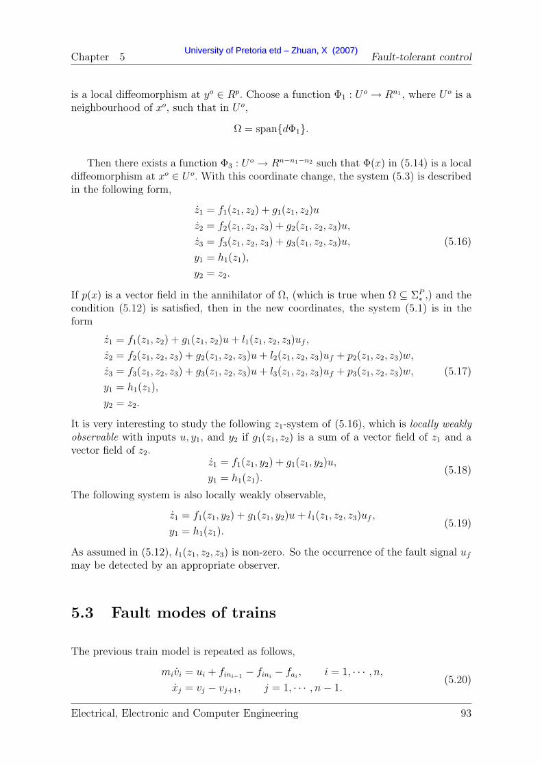
Chapter 5 Fault-tolerant control
is a local diffeomorphism at yo ∈ Rp. Choose a function Φ1 : U o → Rn1 , where U o is aneighbourhood of xo, such that in U o,
Ω = spandΦ1.
Then there exists a function Φ3 : U o → Rn−n1−n2 such that Φ(x) in (5.14) is a localdiffeomorphism at xo ∈ U o. With this coordinate change, the system (5.3) is describedin the following form,
z1 = f1(z1, z2) + g1(z1, z2)u
z2 = f2(z1, z2, z3) + g2(z1, z2, z3)u,
z3 = f3(z1, z2, z3) + g3(z1, z2, z3)u,
y1 = h1(z1),
y2 = z2.
(5.16)
If p(x) is a vector field in the annihilator of Ω, (which is true when Ω ⊆ ΣP∗,) and the
condition (5.12) is satisfied, then in the new coordinates, the system (5.1) is in theform
z1 = f1(z1, z2) + g1(z1, z2)u+ l1(z1, z2, z3)uf ,
z2 = f2(z1, z2, z3) + g2(z1, z2, z3)u+ l2(z1, z2, z3)uf + p2(z1, z2, z3)w,
z3 = f3(z1, z2, z3) + g3(z1, z2, z3)u+ l3(z1, z2, z3)uf + p3(z1, z2, z3)w,
y1 = h1(z1),
y2 = z2.
(5.17)
It is very interesting to study the following z1-system of (5.16), which is locally weaklyobservable with inputs u, y1, and y2 if g1(z1, z2) is a sum of a vector field of z1 and avector field of z2.
z1 = f1(z1, y2) + g1(z1, y2)u,
y1 = h1(z1).(5.18)
The following system is also locally weakly observable,
z1 = f1(z1, y2) + g1(z1, y2)u+ l1(z1, z2, z3)uf ,
y1 = h1(z1).(5.19)
As assumed in (5.12), l1(z1, z2, z3) is non-zero. So the occurrence of the fault signal uf
may be detected by an appropriate observer.
5.3 Fault modes of trains
The previous train model is repeated as follows,
mivi = ui + fini−1− fini
− fai, i = 1, · · · , n,
xj = vj − vj+1, j = 1, · · · , n− 1.(5.20)
Electrical, Electronic and Computer Engineering 93
UUnniivveerrssiittyy ooff PPrreettoorriiaa eettdd –– ZZhhuuaann,, XX ((22000077))

Chapter 5 Fault-tolerant control
With open loop scheduling, one can get the equilibria. Then a difference systembetween the train model and the equilibria is as (3.21), which can be rewritten as
δv = f11(δv) + A12δx+Bδu,
δx = A21δv.(5.21)
where δv = col(δv1, ..., δvn), δx = col(δx1, ..., δxn−1), f11(δv) = [f 111(δv1), ..., f
n11(δvn)]T
in which f i11(δvi) = (c1i
+ 2c2ivr)δvi + c2i
δv2i ,
B = diag(1
m1
, · · · , 1
mn
),
A12 =
− k1
m10 · · · 0 0
k1
m2− k2
m2· · · 0 0
· · · · · · · · · · · · · · ·0 · · · 0 kn−2
mn−1− kn−1
mn−1
0 · · · 0 0 kn−1
mn
,
A21 =
1 −1 0 · · · 0 00 1 −1 · · · 0 0· · · · · · · · · · · · · · · · · ·0 0 0 · · · 1 −1
.
The variables ki, i = 1, · · · , n− 1 are chosen to be constant.
In this thesis, the fault modes include speed senor faults and actuator faults.
5.3.1 Speed sensor faults
The states of a train include the speeds of cars and the relative displacement of thecouplers (in-train forces). It is practical to measure the speeds of cars. The speedsensor may be faulty with a constant bias, and/or with a gain fault due to the gainchange of the amplifier in the circuit. In the former case, such a fault can be correctedby the calibration before its application. In this chapter, the latter case is considered,that is, the sensor for the ith car’s speed is faulty with a gain fault,
vi = (1 +mfvi)vo
i , (5.22)
where the variable vi is the sensor output for the ith car’s speed, voi is the real speed,
and mfvi
is the constant gain fault of the sensor.
Assuming there are q sensors equipped for q cars of the train, and they are locatedat the positions ls1, · · · , lsq, then, the dynamics of a train with speed measurement
Electrical, Electronic and Computer Engineering 94
UUnniivveerrssiittyy ooff PPrreettoorriiaa eettdd –– ZZhhuuaann,, XX ((22000077))

Chapter 5 Fault-tolerant control
(5.21) is as follows,
δv = f11(δv) + A12δx+Bu,
δx = A21δv,
yi = (1 +mfvlsi
)vlsi− vr, i = 1, · · · , q,
(5.23)
where the variable mfvlsi
is the constant gain fault of the ith sensor.
5.3.2 Actuator faults
The actuators of a train include the locomotives’ engines (traction efforts or dynamicbraking forces) and the wagons’ brakes (braking efforts). However, the actuators aresometimes faulty. For example, one locomotive in a locomotive group (composed ofnl locomotives) does not work, then the actual output of the locomotive group is nl−1
nl
of the expected. The air pressure in the braking pipe is sometimes different from thedesigned one owing to air leakage or a fault of the pressure sensor in the air rechargingsystem, which leads to less braking effort in the braking system. In train handling,every locomotive has its own engine, whose running condition is independent with theothers while all wagons share the same braking pressure in the air pipe along the train,whose fault leads to the same faults on all wagons.
In the above cases, the outputs of the actuators may not be equal to those expected,but proportional to the expected ones, i.e.,
ufi = (1 −mi
f )ui, i = 1, · · · , n, (5.24)
in which ui, ufi are expected output and real output, respectively. The output in-
cludes the open loop part uoi and the closed-loop part Ui. The coefficient mi
f is a faultcoefficient. In (5.24), 0 ≤ mi
f ≤ 1.
In the following analysis, one assumes the locomotives’ faults are independent andthe wagons’ faults are the same, i.e.,
ufli
= (1 −mlif )uli , i = 1, · · · , k,
ufj = (1 −mw
f )uj, j = 1, · · · , n, j 6= li.(5.25)
5.4 Fault detection and isolation
5.4.1 Sensor fault detection and isolation
The sensors in train handling are the speed sensors. When the faults of these sensorsare considered and viewed as pseudo-actuators’ faults, the train model described in
Electrical, Electronic and Computer Engineering 95
UUnniivveerrssiittyy ooff PPrreettoorriiaa eettdd –– ZZhhuuaann,, XX ((22000077))

Chapter 5 Fault-tolerant control
(5.23), is as follows.δv = f11(δv) + A12δx+BU,
δx = A21δv,
vflsi
= −vflsi
+ uflsivlsi
,
yi = δvlsi+ vf
lsi, i = 1, · · · , q,
(5.26)
where uflsi
is the pseudo-actuator of the sensor fault. When there is no fault with the
sensor, i.e., vflsi
= 0, the dynamics are vflsi
= −vflsi
+uflsivlsi
, in which uflsi
must be zero.
When there is a fault with the sensor, i.e., vflsi
6= 0, one has uflsi
=v
flsi
vlsi
6= 0 in steady
state. So uflsi
can be thought of as the sensor fault signal.
In the previous chapter, it is assumed that there is a speed sensor for the firstcar (usually a locomotive). It is convenient to assume that this sensor is always ingood condition and the output of this sensor is y1, which can be guaranteed by somehardware structures, for example, a hardware redundancy. With this assumption, forevery sensor fault mode (the output of this sensor is yi, i = 2, · · · , q), the train ismodelled as
δv = f11(δv) + A12δx+BU,
δx = A21δv,
vflsi
= −vflsi
+ uflsivlsi
,
y1 = δv1,
yi = δvlsi+ vf
lsi, i = 2, · · · , q.
(5.27)
When the ith sensor fault uflsi
is considered as uf in (5.1), the other sensor faults
(uflsj, j ∈ [2, q], j 6= i) are thought as w in (5.1) to be decoupled. Then in the form of
(5.1), one has x = [δv, δx, vfls]
T , u = U, uf = uflsi, w = (uf
lsj), j ∈ [2, q], j 6= i,
f(x) =
[f11(δv) + A12δx
A21δv
]
,
g(x) = B,
l(x) = [
n−2+i︷ ︸︸ ︷
0, · · · , 0, vlsi,
q−i︷ ︸︸ ︷
0, · · · , 0]T ,
pj(x) = [
n−2+j︷ ︸︸ ︷
0, · · · , 0, vlsj,
q−j︷ ︸︸ ︷
0, · · · , 0]T , j ∈ [2, q], j 6= i,
and
h(x) =
δv1
δvls2
· · ·δvlsq
.
Electrical, Electronic and Computer Engineering 96
UUnniivveerrssiittyy ooff PPrreettoorriiaa eettdd –– ZZhhuuaann,, XX ((22000077))

Chapter 5 Fault-tolerant control
For the system (5.27), assuming the co-distribution
Θ = Ω0 = spand(δv1), · · · , d(δvn), d(δx1), d(δxn−1)in the observability co-distribution algorithm (5.9), one has,
spandh = spand(δv1), d(δvls2+ vf
ls2), · · · , d(δvlsq
+ vflsq
),Q0 = Ω0 ∩ spandh = spand(δv1),
Q0 =m∑
i=0
LgiQ0 + spandh
= spand(δv1), d(δx1), d(δvls2+ vf
ls2), · · · , d(δvlsq
+ vflsq
),Q1 = Ω0 ∩ Q0 = spand(δv1), d(δx1),
Q1 =m∑
i=0
LgiQ1 + spandh
= spand(δv1), d(δv2), d(δx1), d(δvls2+ vf
ls2), · · · , d(δvlsq
+ vflsq
),Q2 = Ω0 ∩ Q1 = spand(δv1), d(δv2), d(δx1),
· · · ,Q2n−1 = spand(δv1), · · · , d(δvn−1), d(δx1), · · · , d(δxn−1),
Q2n−1 =m∑
i=0
LgiQ1 + spandh = spand(δv1), · · · , d(δvn),
d(δx1), · · · , d(δxn−1), d(δvls2+ vf
ls2), · · · , d(δvlsq
+ vflsq
),Q2n = spand(δv1), · · · , d(δvn), d(δx1), · · · , d(δxn−1).
Then Qk = Q2n,∀k > 2n, which results in o.c.a(Ω0) = Q2n = Ω0.
Considering the co-distribution Ω = Ω0 + spand(vflsj
), i.e.,
Ω = spand(δv1), · · · , d(δvn), d(δx1), d(δxn−1), d(vflsj
),∀j ∈ [2, q],
one has o.c.a(Ω) ⊇ o.c.a(Ω0).
Then from (5.10), one has Q′
i ⊇ Qi and Q′
i ⊇ Qi where Q′
i and Q′
i are the calculationresults with Ω and Qi and Qi with Ω0. Then one has Q′
2n−1 ⊇ Q2n−1 and furthermore
Q′
2n = (Ω ∩ Q′
2n−1)
⊇ (Ω ∩ Q2n−1)
= spand(δv1), · · · , d(δvn), d(δx1), d(δxn−1), d(vflsj
)= Ω,
which means o.c.a(Ω) ⊇ Q′
2n ⊇ Ω. As is known, o.c.a(Ω) ⊆ Ω, so o.c.a(Ω) = Ω.
Furthermore, one has
LgjΩ ⊂ Ω = Ω + spandh,∀j ∈ [0,m]. (5.28)
Electrical, Electronic and Computer Engineering 97
UUnniivveerrssiittyy ooff PPrreettoorriiaa eettdd –– ZZhhuuaann,, XX ((22000077))

Chapter 5 Fault-tolerant control
The conditions in (5.11) are satisfied, i.e., Ω is an observability co-distribution.
It is obvious that the vector field pj, j ∈ [2, p], j 6= i is in the annihilator of Ω whilespanl ⊂ Ω. So it is possible to transform the train dynamics with sensor faults (5.27)into the form of (5.17), which means the possibility of fault detection of ith sensorfault.
A residual generator for the ith sensor can be in the following form,
ξ1 = f11(ξ1) + A12ξ2 +BU + L11(y1 − ξ11) + L13(yi − ξ1,lsi),
ξ2 = A21ξ1 + L21(y1 − ξ11) + L23(yi − ξ1,lsi),
ξ3 = −ξ3 + L31(y1 − ξ11) + L33(yi − ξ1,lsi),
ri = (yi − ξ1,lsi)/(vr + ξ1,lsi
), i ∈ [2, p].
(5.29)
where ξ1 = col(ξ11, · · · , ξ1n) ∈ Rn, ξ2 = col(ξ21, · · · , ξ2,n−1) ∈ Rn−1, ξ3 ∈ R. In theabove equation, Lij are chosen by observer design approaches, such as pole placement(Luenberger observer) or optimization control (Kalman filter).
Especially, when L13 = 0, L23 = 0, it is also possible for the above form of dynamicsto be a residual generator, because the original system without the faulty output isalso observable, which has been proved in the previous chapter. It is very interestingto observe that this residual generator is naturally a fault identifier because the faultsignal does not affect the states ξ1, ξ2, and the residual signal is actually the identifiersignal of the fault. Furthermore, in this way, the residual generators and identifiers ofall the sensor faults can share the same dynamics with different outputs, i.e.,
ξ1 = f11(ξ1) + A12ξ2 +BU + L11(y1 − ξ11),
ξ2 = A21ξ1 + L21(y1 − ξ11),(5.30)
and the output (a residual generator as well as a identifier) for the ith sensor fault is
ri =y2 − ξ1,lsi
ξ1,lsi+ vr
. (5.31)
5.4.2 Actuator fault detection and isolation
A locomotive group effort is sometimes not the same as the expected one for somereasons, such as one locomotive of the locomotive group not working. The brakingefforts of wagons may be different from the expected, because of the pressure changein the braking pipe. In the following, only the fault modes as in (5.24) are studied.
When this happens, the efforts of the cars are proportional to the expected efforts,that is, the fault mode described in (5.25) is repeated as follows,
δv = f11(δv) + A12δx+BU +Bf (U + uo),
δx = A21δv,(5.32)
Electrical, Electronic and Computer Engineering 98
UUnniivveerrssiittyy ooff PPrreettoorriiaa eettdd –– ZZhhuuaann,, XX ((22000077))

Chapter 5 Fault-tolerant control
where Bf = diag(ml1f /m1,
n−2︷ ︸︸ ︷
mwf /m2, · · · ,mw
f /mn−1,ml2f /mn).
To detect the actuators’ faults, some states are assumed to be measurable. In thisstudy, the train is assumed to be composed of n cars with one locomotive (group) at thefront and one at the rear. The wagons are between these two locomotives (locomotivegroups). The speeds of the two locomotives and the two wagons next to the locomotivesare also available, i.e.,
y =
v1
v2
vn−1
vn
. (5.33)
The two kinds of fault modes (sensor fault and actuator fault) are studied separately,because there are some difficulties in studying these two kinds of faults simultaneously,which will be discussed later. So, in the study of actuator faults, the speed sensors areassumed to be in good condition.
Locomotive fault detection and isolation
The locomotive group fault diagnosis is not studied in this chapter. Some approachesmay be used to supervise the running states of the locomotives, such as in [69, 70, 67,68, 71]. In this thesis, one assumes that the fault diagnosis signals and fault isolationsignals are given, and when a fault happens, one’s task is to reconfigure/redesign thecontroller.
Wagon fault detection and isolation
When the wagon faults in the system (5.32) are concerned, in the form of (5.1) for thealgorithms in section 5.2, one has
x =
[δvδx
]
∈ R2n−1,
u = U,
uf = mwf ,
w =
[m1
f
mnf
]
,
f(x) =
[f11(δv) + A12δx
A21δv
]
,
g(x) = B,
Electrical, Electronic and Computer Engineering 99
UUnniivveerrssiittyy ooff PPrreettoorriiaa eettdd –– ZZhhuuaann,, XX ((22000077))

Chapter 5 Fault-tolerant control
l = [0, (U2 + uo2)/m2, · · · , (Un−1 + uo
n−1)/mn−1,
n︷ ︸︸ ︷
0, · · · , 0 ]T ,
p1 = [(U1 + uo1)/m1,
n−2︷ ︸︸ ︷
0, · · · , 0,n
︷ ︸︸ ︷
0, · · · , 0 ]T ,
p2 = [
n−1︷ ︸︸ ︷
0, · · · , 0, (Un + uon)/mn,
n−1︷ ︸︸ ︷
0, · · · , 0 ]T ,
andh(x) = [δv1, δv2, δvn−1, δvn]T .
According to the algorithm (5.7), one has
S0 = P = spanp1, p2,S0 ∩ kerdh = 0,
· · · ,Sk∗ = spanp1, p2.
from which one has
(ΣP∗)⊥ = spanδv2, · · · , δvn−1, δx1, . . . , δxn−1.
Furthermore, applying the algorithm (5.9) with Θ = (ΣP∗)⊥, one has
spandh = spand(δv1), d(δv2), d(δvn−1), d(δvn),Q0 = Θ ∩ spandh = spanδv2, δvn−1,
Q0 =m∑
i=0
LgiQ0 + spandh = spand(δv1), d(δv2), d(δvn−1), d(δvn),
d(k1δx1 − k2δx2), d(kn−2δxn−2 − kn−1δxn−1),Q1 = Θ ∩ Q0 = spand(δv2), d(δvn−1),
d(k1δx1 − k2δx2), d(kn−2δxn−2 − kn−1δxn−1),
Q1 =m∑
i=0
LgiQ1 + spandh
= spand(δv1), d(δv2), d(δv3), d(δvn−2), d(δvn−1), d(δvn),
d(k1δx1 − k2δx2), d(kn−2δxn−2 − kn−1δxn−1),Q2 = Θ ∩ Q1 = spand(δv2), d(δv3), d(δvn−2), d(δvn−1),
d(k1δx1 − k2δx2), d(kn−2δxn−2 − kn−1δxn−1),· · · ,
Qk∗ = spand(δv2), · · · , d(δvn−1), d(k1δx1 − k2δx2),
· · · , d(kn−2δxn−2 − kn−1δxn−1),that is,
Ω = o.c.a((ΣP∗)⊥) = spand(δv2), · · · , d(δvn−1), d(k1δx1 − k2δx2),
· · · , d(kn−2δxn−2 − kn−1δxn−1).(5.34)
Electrical, Electronic and Computer Engineering 100
UUnniivveerrssiittyy ooff PPrreettoorriiaa eettdd –– ZZhhuuaann,, XX ((22000077))

Chapter 5 Fault-tolerant control
Repeat the above algorithm with Θ = Ω, and one has
Ω = o.c.a(Ω).
The second condition in (5.11) is satisfied. Then one can verify the first condition in(5.11).
LgΩ = spand(k1δv1 − (k1 + k2)δv2 + k2δv3),
· · · ,d(kn−2δvn−2 − (kn−2 + kn−1)δvn−1 + kn−1δvn),
d(k1δx1 − k2δx2),
· · · ,d(kn−2δxn−2 − kn−1δxn−1),
and
Ω + spandh = spand(δv1), d(δv2), · · · , d(δvn−2), d(δvn−1),
d(k1δx1 − k2δx2), · · · , d(kn−2δxn−2 − kn−1δxn−1),
so LgjΩ ⊂ Ω + spandh,∀j ∈ [0,m].
The conditions in (5.11) are satisfied with Ω defined above, which means the co-distribution Ω is the maximal observability co-distribution contained in P⊥.
Assuming z11 = δv2, z12 = δv3, · · · , z1,n−2 = δvn−1, and z1,n−1 = k1δx1 − k2δx2, · · · ,z1,2n−4 = kn−2δxn−2 − kn−1δxn−1, the z1-system of (5.13) is as follows:
z11 = f 211(z11) + z1,n−1/m2 + U2/m2,
· · · ,z1,n−2 = fn−1
11 (z1,n−2) + z1,2n−4/mn−1 + Un−1/mn−1,
z1,n−1 = k1δv1 − (k1 + k2)z11 + k2z12,
z1,n = k2z11 − (k2 + k3)z12 + k3z13,
· · · ,z1,2n−5 = kn−3z1,n−4 − (kn−3 + kn−2)z1,n−3 + kn−2z1,n−2,
z1,2n−4 = kn−2z1,n−3 − (kn−2 + kn−1)z1,n−2 − kn−1δvn
y1 = col(z11, z1,n−2),
y2 = col(δv1, δvn).
(5.35)
It can also be seen that spanl ⊂ Ω, which means the possibility of detectability ofthe wagon fault.
Electrical, Electronic and Computer Engineering 101
UUnniivveerrssiittyy ooff PPrreettoorriiaa eettdd –– ZZhhuuaann,, XX ((22000077))

Chapter 5 Fault-tolerant control
A residual generator is in the following form,
ξ11 = f 211(ξ11) + ξ21/m2 + U2/m2 + L11(ξ11 − y11) + L12(ξ1,n−2 − y12),
· · · ,ξ1,n−2 = fn−1
11 (ξ1,n−2) + ξ2,n−2/mn−1 + Un−1/mn−1
+ Ln−2,1(ξ11 − y11) + Ln−2,2(ξ1,n−2 − y12),
ξ2,1 = k1y21 − (k1 + k2)ξ11 + k2ξ12
+ Ln−1,1(ξ11 − y11) + Ln−1,2(ξ1,n−2 − y12),
ξ2,i = kiξ11 − (ki + ki+1)ξ1,i + ki+1ξ1,i+1
+ Li+n−2,1(ξ11 − y11) + Li+n−2,2(ξ1,n−2 − y12), i = 2, · · · , n− 3,
ξ2,n−2 = kn−2ξ1,n−3 − (kn−2 + kn−1)ξ1,n−2 + kn−1y22 + L2n−4,1(ξ11 − y11)
+ L2n−4,2(ξ1,n−2 − y12),
y1 = col(δv2, δvn−1),
y2 = col(δv1, δvn),
(5.36)
where the matrix L = (Lij) is suitably chosen with observer design approaches, suchas pole placement (Luenberger observer) or optimization control (Kalman filter).
From (5.36), it can be seen that the dimension of the observer is 2n− 4. For a longtrain, n is very large. To avoid such a high-dimension observer, one considers anotherapproach to identify the wagons’ faults. The full train model is repeated as follows:
mivi = (1 −mif )ui + fini−1
− fini−mi(c0i
+ c1ivi + c2i
v2i ) − fpi
, i = 1, · · · , n,xj = vj − vj+1, j = 1, · · · , n− 1,
(5.37)
where fin0= 0, finn
= 0.
When mif = 0, one has reached an equilibrium (steady state, v = 0, x = 0) vi =
vr, i = 1, · · · , n, and f 0inj
(x0j), with ui = u0
i .
vr = u0i + f 0
ini−1− f 0
ini−mi(c0i
+ c1ivr + c2i
v2r) − fpi
, i = 1, · · · , n,x0
j = vr − vr, j = 1, · · · , n− 1.(5.38)
Thus one has a difference system (5.21) with δvi = vi − vr, δxj = xj − x0j , which is also
denoted as follows,X = f(X) +BU. (5.39)
A speed regulator designed in the previous chapter for this difference system isrepeated as follows,
z = f(z) +BU +G1(ym − Cmz),
U = c(w) +K(z − π(w)),(5.40)
Electrical, Electronic and Computer Engineering 102
UUnniivveerrssiittyy ooff PPrreettoorriiaa eettdd –– ZZhhuuaann,, XX ((22000077))

Chapter 5 Fault-tolerant control
The closed-loop dynamics are
X = f(X) +BU,
z = f(z) +BU +G1(ym − Cmz),
U = c(w) +K(z − π(w)).
(5.41)
When the train is faultless, the train speed will track the reference speed underthe above controller. How are the train’s dynamics when mi
f 6= 0? One first checkswhether the train dynamics are stable. If they are, then one will study the new steadystates.
The locomotives’ faults are assumed to be detected and isolated through otherapproaches, so only the faults of the wagons with mi
f = mwf , i = 2, · · · , n − 1 are
considered in the following identification.
When mwf 6= 0, the closed-loop dynamics (5.41) in cruise phase is as follows
X = f(X) +BU −Bf (U + uo),
z = f(z) +BU +G1(ym − Cmz),
U = Kz,
(5.42)
where Bf = diag(0,
n−2︷ ︸︸ ︷
mwf /m2, · · · ,mw
f /mn−1,
n︷ ︸︸ ︷
0, · · · , 0 ).
Assuming A = ∂f(0)∂X
, (from the above, one knows A+BK < 0, A+G1Cm < 0,) onehas a linearized model as follows:
X = AX + (B −Bf )Kz −Bfuo,
z = −GCmX + (A+G1Cm +BK)z.(5.43)
If the K, G are chosen such that
[A (B −Bf )K
−GC A+GC +BK
]
< 0,
then the above system (5.43) is stable.
The steady state of the train can be denoted as (v = 0, x = 0) vi = vfr , i = 1, · · · , n,
and f finj
(xfj ), with ui,
m1vfr = u1 − f f
in1−m1(c01
+ c11vf
r + c21(vf
r )2) − fp1,
mivfr = ui + f f
ini−1− f f
ini−mi(c0i
+ c1ivf
r + c2i(vf
r )2) − fpi−mi
fui, i = 2, · · · , n− 1,
mnvfr = un + f f
inn−mn(c0n
+ c1nvf
r + c2n(vf
r )2) − fpn,
(5.44)
Electrical, Electronic and Computer Engineering 103
UUnniivveerrssiittyy ooff PPrreettoorriiaa eettdd –– ZZhhuuaann,, XX ((22000077))
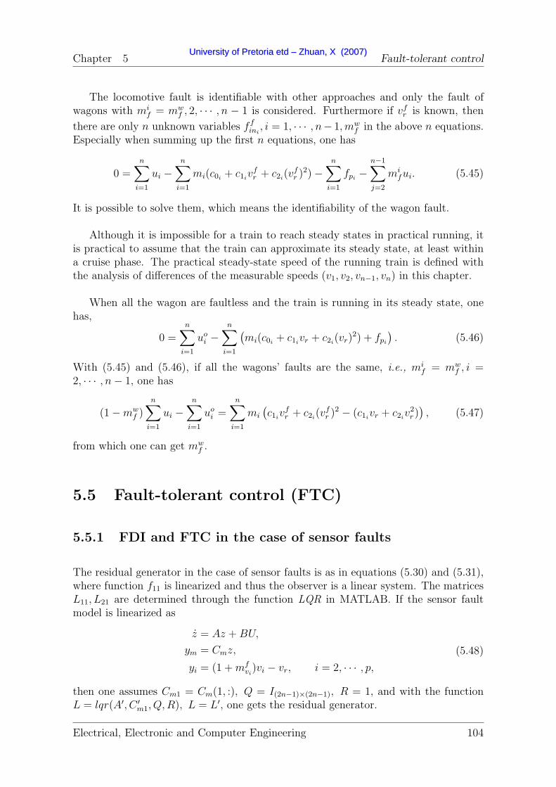
Chapter 5 Fault-tolerant control
The locomotive fault is identifiable with other approaches and only the fault ofwagons with mi
f = mwf , 2, · · · , n − 1 is considered. Furthermore if vf
r is known, then
there are only n unknown variables f fini, i = 1, · · · , n− 1,mw
f in the above n equations.Especially when summing up the first n equations, one has
0 =n∑
i=1
ui −n∑
i=1
mi(c0i+ c1i
vfr + c2i
(vfr )2) −
n∑
i=1
fpi−
n−1∑
j=2
mifui. (5.45)
It is possible to solve them, which means the identifiability of the wagon fault.
Although it is impossible for a train to reach steady states in practical running, itis practical to assume that the train can approximate its steady state, at least withina cruise phase. The practical steady-state speed of the running train is defined withthe analysis of differences of the measurable speeds (v1, v2, vn−1, vn) in this chapter.
When all the wagon are faultless and the train is running in its steady state, onehas,
0 =n∑
i=1
uoi −
n∑
i=1
(mi(c0i
+ c1ivr + c2i
(vr)2) + fpi
). (5.46)
With (5.45) and (5.46), if all the wagons’ faults are the same, i.e., mif = mw
f , i =2, · · · , n− 1, one has
(1 −mwf )
n∑
i=1
ui −n∑
i=1
uoi =
n∑
i=1
mi
(c1ivf
r + c2i(vf
r )2 − (c1ivr + c2i
v2r)), (5.47)
from which one can get mwf .
5.5 Fault-tolerant control (FTC)
5.5.1 FDI and FTC in the case of sensor faults
The residual generator in the case of sensor faults is as in equations (5.30) and (5.31),where function f11 is linearized and thus the observer is a linear system. The matricesL11, L21 are determined through the function LQR in MATLAB. If the sensor faultmodel is linearized as
z = Az +BU,
ym = Cmz,
yi = (1 +mfvi)vi − vr, i = 2, · · · , p,
(5.48)
then one assumes Cm1 = Cm(1, :), Q = I(2n−1)×(2n−1), R = 1, and with the functionL = lqr(A′, C ′
m1, Q,R), L = L′, one gets the residual generator.
Electrical, Electronic and Computer Engineering 104
UUnniivveerrssiittyy ooff PPrreettoorriiaa eettdd –– ZZhhuuaann,, XX ((22000077))

Chapter 5 Fault-tolerant control
In the controller, one assumes the outputs of the residual generator are vi andthe measured speeds vmi. The reference speed is vr. In the control process, for theoutput vmi of the ith speed sensor, one will take Ksensor
i × vmi as the real speed ofthe corresponding car, where Ksensor
i is a coefficient, which will be modified when thesensor fault is detected and isolated. A constant Vth is set as the threshold of faultdiagnosis. For the fault detection and isolation, one has other arrays in the programme,KDsensor
i,1:11 , Nsensori. The former is used to store the past 11 coefficients of the sensorand the latter the times of continuous violations of the fault-free condition.
The fault detection and isolation programme is shown as Fig. 5.1, whereKDsensori,1:11 =
01×11, Nsensori = 0 and Ksensor
i = 1 are initialized. This programme is executed once asecond.
It is known that there is a possibility of false rejections and a possibility of falseacceptances for a fault-tolerant controller, which should be considered. The first pos-sibility is that it does not detect or isolate the fault well when a fault occurs. Thesecond is that it takes a faultless system as a fault system. The choice of the thresh-olds affect these two possibilities. Generally, when one possibility is reduced with a setof thresholds, the other one is increased. When the threshold is to be determined, thebalance between the two possibilities should be considered. From Fig. 5.1, it is impos-sible to avoid the above two possibilities. However, the effects of the possibility of falseacceptance can be discussed qualitatively. If a fault is falsely accepted, for example, asensor with a gain 1 is falsely identified with a gain 1.05, then with the FTC, the speedof the train will be underestimated, and thus the train will be overspeed. In that case,the FDI will further identify a gain fault lower than 1 to correct the false acceptance.It is in the way of “negative feedback” to track the real value of the gain. Such anapproach in Fig. 5.1 does not obviously affect the train performance. That can be seenfrom the simulation results of an FTC in a faultless system.
In this thesis, the two possibilities from theoretic viewpoints will not be discussed,nor will the time delay between the fault occurrence and fault isolation. Instead, theywill be discussed on the basis of the simulation results.
5.5.2 Controller redesign in the case of a locomotive fault
As described before, fault detection and isolation of locomotive faults are not studiedin this thesis. Here, only the fault-tolerant control of a locomotive fault is considered.
In the following simulation, one assumes the fault is detected and identified 60 sec-onds after it occurs. When it is identified, the controller will be redesigned. Accordingto the fault, the parameters of the train are modified and then the controller is re-designed with the new parameters. For example, assuming the coefficient of its inputin the train model is Bt(i, :), if the locomotive group u(i) loses half its effort, the newcoefficient is Bt(i, :)/2.
Electrical, Electronic and Computer Engineering 105
UUnniivveerrssiittyy ooff PPrreettoorriiaa eettdd –– ZZhhuuaann,, XX ((22000077))

Chapter 5 Fault-tolerant control
Figure 5.1: Sensor fault detection and isolation programme
Electrical, Electronic and Computer Engineering 106
UUnniivveerrssiittyy ooff PPrreettoorriiaa eettdd –– ZZhhuuaann,, XX ((22000077))

Chapter 5 Fault-tolerant control
5.5.3 FDI and FTC in the case of a wagon fault
When a wagon fault is detected and identified, similar to the case of a locomotive fault,the controller will be redesigned according to the updated parameters of the train. Thekey is fault detection and isolation. In the current simulation, this is done followingthe approach proposed in section 5.4.2.
In this approach, one employs the algorithm as Fig. 5.2 to detect and identify thefault; this is executed once a second. In the figure, the matrix Bb is the coefficientmatrix of the brake inputs in the train model, which is equal to diag(1/mi) when thebraking system is faultless. The variables vm, vr are the measured speed and referencespeed, respectively. The variable Kf
brake is a ten-dimension array used to store the past
ten estimated fault signals, while N fbrake is a counter number of the continuous violation
of fault condition.
There are the same possibilities in the FDI of a wagon fault as in the FDI of asensor fault. Similar to the latter, the FDI of wagon faults is also “negative feedback”to track the real value of the wagon actuator. The effect of false acceptance on thetrain performance will not be discussed in a theoretic way, but is discussed with thesimulation results. The time delay between the fault occurrence and fault isolation willnot be discussed either.
5.6 Simulation
The simulation setting of the train is the same as previous chapters as well as the speedprofile and track profile. When all sensors and actuators are faultless, the controller isthe speed regulator with Ke = 1, Kf = 1, Kv = 1, designed in part 4.3. When a faultoccurs, the controller will be redesigned. The controller redesign includes two parts:the redesign of the optimal scheduling and the redesign of the speed regulator.
5.6.1 Simulation of sensor faults
In simulation, the sensor fault detection and isolation programme is only workingduring the cruise phase. The simulation setting is the same as in section 4.3. The faultdiagnosis parameter setting is as in Fig. 5.1.
There are two kinds of errors with the gains of speed sensors. One is a randomerror, which depends on the accuracy of speed sensor. The other one is a systematicerror with gain, which is a real fault and should be corrected. From the simulation, itwill be seen that the former has little impact on the performance of controllers, while
Electrical, Electronic and Computer Engineering 107
UUnniivveerrssiittyy ooff PPrreettoorriiaa eettdd –– ZZhhuuaann,, XX ((22000077))

Chapter 5 Fault-tolerant control
Figure 5.2: Wagon fault detection and isolation programme
Electrical, Electronic and Computer Engineering 108
UUnniivveerrssiittyy ooff PPrreettoorriiaa eettdd –– ZZhhuuaann,, XX ((22000077))

Chapter 5 Fault-tolerant control
the latter has much greater impact.
In the following description, the accuracy 1±α% of a speed sensor means the outputof the sensor is randomly 1 ± α% of the measured speed, while the gain fault β% ofa sensor means the output of the sensor is 1 + β% of the measured speed with theaccuracy 1.
The effects of the random errors of the speed sensors on the non-FTC (a controllerwithout fault-tolerant capacity) and the FTC (a controller with fault-tolerant capacity)are discussed firstly. The following three groups of figures are the simulation resultswith non-FTC of a faultless system, FTC of a faultless system and FTC of a faultysystem, respectively.
Fig. 5.3 and Fig. 5.4 are the simulation results of a faultless system with non-FTC.All sensors in the former case have accuracies of 100%, while those in the latter haveaccuracies of 1 ± 5% from the beginning.
10
12
14
16
spee
d(m
/s) ref speed
front speedrear speedmean speed
−500
0
500
1000
intr
ain
forc
e(kN
)
max in−train forcemin in−train forcemean in−train force
−4000 −2000 0 2000 4000 6000 8000 10000−2
0
2
4
distance (m)
notc
h
front notchrear notch
Figure 5.3: Non-FTC (sensor accuracy of 100%)
Fig. 5.5 and Fig. 5.6 are simulation results of a faultless system with an FTC.All sensors in the former case have accuracies of 100%, while those in the latter haveaccuracies of 1 ± 5% from the beginning.
Fig. 5.7 and Fig. 5.8 are the simulation results of a faulty system (the second sensor
Electrical, Electronic and Computer Engineering 109
UUnniivveerrssiittyy ooff PPrreettoorriiaa eettdd –– ZZhhuuaann,, XX ((22000077))

Chapter 5 Fault-tolerant control
10
12
14
16sp
eed(
m/s
) ref speedfront speedrear speedmean speed
−500
0
500
1000
intr
ain
forc
e(kN
)
max in−train forcemin in−train forcemean in−train force
−4000 −2000 0 2000 4000 6000 8000 10000−2
0
2
4
distance (m)
notc
h
front notchrear notch
Figure 5.4: Non-FTC (sensor accuracy of 1 ± 5%)
10
12
14
16
spee
d(m
/s) ref speed
front speedrear speedmean speed
−500
0
500
1000
intr
ain
forc
e(kN
)
max in−train forcemin in−train forcemean in−train force
−4000 −2000 0 2000 4000 6000 8000 10000−2
0
2
4
distance (m)
notc
h
front notchrear notch
Figure 5.5: FTC (sensor accuracy of 100%)
Electrical, Electronic and Computer Engineering 110
UUnniivveerrssiittyy ooff PPrreettoorriiaa eettdd –– ZZhhuuaann,, XX ((22000077))

Chapter 5 Fault-tolerant control
10
12
14
16sp
eed(
m/s
) ref speedfront speedrear speedmean speed
−500
0
500
1000
intr
ain
forc
e(kN
)
max in−train forcemin in−train forcemean in−train force
−4000 −2000 0 2000 4000 6000 8000 10000−2
0
2
4
distance (m)
notc
h
front notchrear notch
Figure 5.6: FTC (sensor accuracy of 1 ± 5%)
is faulty with a gain fault +5%). All sensors in the former case have accuracies of 100%while those in the latter have accuracies of 1 ± 5%.
Comparing Fig. 5.3 with Fig. 5.4, one can see that the random error has verylittle effect on the speed regulators without fault-tolerant capacity when there is nofault with the sensors. Comparing Fig. 5.5 with Fig. 5.6, it can be seen that therandom error makes the performance a little worse with the fault-tolerant controllereven though no fault occurs. The effects are, however, very small. The performanceindex is referred to in Table 5.1. From a comparison of Fig. 5.7 with Fig. 5.8, one seesthat the random errors of sensors have little impact on the performance of the fault-tolerant controllers when a fault occurs with the second sensor. From a comparison ofthe last two pairs, it is concluded that random errors have effects on the performance ofthe fault-tolerant controllers, but the effects are limited. The result is still acceptable.In the following simulation of this study, one therefore seldom considers the randomerrors of the sensors. From the above discussion, it is clear the results are not affected.
A discussion of the effects of the FTC on the performance of a speed regulator isas below.
The figures from Fig. 5.3 to Fig. 5.9 are compared. Fig. 5.9 is the simulation resultof a faulty system (the second sensor is faulty with a gain fault +5%) with all sensorshaving accuracies of 1 ± 5%. The controller in this simulation is a non-FTC.
Electrical, Electronic and Computer Engineering 111
UUnniivveerrssiittyy ooff PPrreettoorriiaa eettdd –– ZZhhuuaann,, XX ((22000077))

Chapter 5 Fault-tolerant control
10
12
14
16sp
eed(
m/s
) ref speedfront speedrear speedmean speed
−500
0
500
1000
intr
ain
forc
e(kN
)
max in−train forcemin in−train forcemean in−train force
−4000 −2000 0 2000 4000 6000 8000 10000−2
0
2
4
distance (m)
notc
h
front notchrear notch
Figure 5.7: FTC (sensor accuracy of 1 + 0% and second sensor gain fault of +5% )
10
12
14
16
spee
d(m
/s) ref speed
front speedrear speedmean speed
−500
0
500
1000
intr
ain
forc
e(kN
)
max in−train forcemin in−train forcemean in−train force
−4000 −2000 0 2000 4000 6000 8000 10000−2
0
2
4
distance (m)
notc
h
front notchrear notch
Figure 5.8: FTC (sensor accuracy of 1 ± 5% and second sensor gain fault of +5%)
Electrical, Electronic and Computer Engineering 112
UUnniivveerrssiittyy ooff PPrreettoorriiaa eettdd –– ZZhhuuaann,, XX ((22000077))

Chapter 5 Fault-tolerant control
10
12
14
16sp
eed(
m/s
) ref speedfront speedrear speedmean speed
−500
0
500
1000
intr
ain
forc
e(kN
)
max in−train forcemin in−train forcemean in−train force
−4000 −2000 0 2000 4000 6000 8000 10000−2
0
2
4
distance (m)
notc
h
front notchrear notch
Figure 5.9: Non-FTC (sensor accuracy of 1± 5% and 2nd sensor gain fault of +5%)
One first compares Fig. 5.3 with Fig. 5.5, in which the sensors have accuracies of100% and the system is faultless. The former is controlled with a non-FTC whilethe latter is controlled with an FTC. From these two figures, one can see that theperformance is visually very similar although from Table 5.1 the last one appears tobe slightly worse.
Then Fig. 5.4 is compared with Fig. 5.6, in which the sensors have accuracies of1± 5% and the system is faultless. The former is controlled with a non-FTC while thelatter is controlled with an FTC. The speed performance of the latter is a little worsethan that of the former, and even the latter has a steady speed error. This is becausethe random errors of the sensors have an effect on the performance of an FTC. Evenso, the FTC does not explicitly worsen the performance of the speed regulator. Theresult is still acceptable.
The advantage of an FTC can be seen when a fault occurs. Fig. 5.9 and Fig. 5.8represent simulation of a faulty system (all sensors with accuracies of 1 ± 5% and thesecond one has a gain fault of +5%) with a non-FTC and with an FTC, respectively.It is seen that the speed performance of the latter is obviously better than that of theformer. That is the contribution of the FTC. From the above comparison, one canconclude that
1) When no fault occurs and all sensors have accuracies of 100%, the speed perfor-
Electrical, Electronic and Computer Engineering 113
UUnniivveerrssiittyy ooff PPrreettoorriiaa eettdd –– ZZhhuuaann,, XX ((22000077))

Chapter 5 Fault-tolerant control
mance of an FTC is very similar to that of a non-FTC.
2) When no fault occurs and all sensors have accuracies of 1±5%, the speed perfor-mance of an FTC is a little worse than that of a non-FTC. However, the resultis still thought as a good result.
3) When a small fault (the second sensor has a gain fault of +5%) occurs and allsensors have accuracies of 1 ± 5%, the speed performance of an FTC is muchbetter than that of a non-FTC.
From the above, it is concluded that the FTC for the sensors’ faults is suitable.
In the above simulations, only the FTC for the second sensor fault is given. In thefollowing, one can see the FTC applied in the faults of the third and fourth sensors,and in the concurrent faults of the second and fourth ones. Since the accuracy of asensor does not explicitly affect the performance of the controller, without a specialdescription, the sensor accuracy is assumed to be 100% in the rest of this thesis.
Fig. 5.10 shows an FTC with the third sensor having a gain fault of +7% from thebeginning. Fig. 5.11 shows an FTC with the fourth sensor having a gain fault of −20%from the beginning. Fig. 5.12 shows an FTC with the fourth sensor having a gain faultof +20% from the beginning.
A kind of concurrent fault (the second sensor has a gain fault of +43% and thefourth one has a gain fault of +12% from the beginning) is shown in Fig. 5.13 with anFTC. Another kind of concurrent fault (the second sensor has a gain fault of +30%from the distance of 2, 000 m and the fourth one has a gain fault of −30% from thedistance of 4, 000 m) is shown in Fig. 5.14 with an FTC.
The comparison of these figures in performance is shown in Table 5.1. The statisticalitems are the same as those in the Table 4.1.
From an analysis of the figures and a comparison with Table 5.1, one can concludethat the application of FTC of sensor faults in the speed regulation explicitly improvesperformance in the case of fault occurrence and does not explicitly worsen performancein the case of a faultless train.
5.6.2 Simulation of locomotive faults
In the previous parts, fault detection and isolation of locomotive faults are assumed tobe done by other approaches and only fault-tolerant control is considered in this thesis.The fault signal is assumed to be given when a fault occurs.
In the train setting of simulation, there are two groups of locomotives at the front
Electrical, Electronic and Computer Engineering 114
UUnniivveerrssiittyy ooff PPrreettoorriiaa eettdd –– ZZhhuuaann,, XX ((22000077))

Chapter 5 Fault-tolerant control
10
12
14
16sp
eed(
m/s
) ref speedfront speedrear speedmean speed
−500
0
500
1000
intr
ain
forc
e(kN
)
max in−train forcemin in−train forcemean in−train force
−4000 −2000 0 2000 4000 6000 8000 10000−2
0
2
4
distance (m)
notc
h
front notchrear notch
Figure 5.10: FTC (third sensor with a gain fault of +7%)
10
12
14
16
spee
d(m
/s) ref speed
front speedrear speedmean speed
−500
0
500
1000
intr
ain
forc
e(kN
)
max in−train forcemin in−train forcemean in−train force
−4000 −2000 0 2000 4000 6000 8000 10000−2
0
2
4
distance (m)
notc
h
front notchrear notch
Figure 5.11: FTC (fourth sensor with a gain fault of −20%)
Electrical, Electronic and Computer Engineering 115
UUnniivveerrssiittyy ooff PPrreettoorriiaa eettdd –– ZZhhuuaann,, XX ((22000077))

Chapter 5 Fault-tolerant control
10
12
14
16sp
eed(
m/s
) ref speedfront speedrear speedmean speed
−500
0
500
1000
intr
ain
forc
e(kN
)
max in−train forcemin in−train forcemean in−train force
−4000 −2000 0 2000 4000 6000 8000 10000−2
0
2
4
distance (m)
notc
h
front notchrear notch
Figure 5.12: FTC (fourth sensor with a gain fault of +20%)
8
10
12
14
16
spee
d(m
/s) ref speed
front speedrear speedmean speed
−500
0
500
1000
intr
ain
forc
e(kN
)
max in−train forcemin in−train forcemean in−train force
−4000 −2000 0 2000 4000 6000 8000 10000−2
0
2
4
distance (m)
notc
h
front notchrear notch
Figure 5.13: FTC (concurrent faults)
Electrical, Electronic and Computer Engineering 116
UUnniivveerrssiittyy ooff PPrreettoorriiaa eettdd –– ZZhhuuaann,, XX ((22000077))

Chapter 5 Fault-tolerant control
10
12
14
16
spee
d(m
/s) ref speed
front speedrear speedmean speed
−1000
0
1000
intr
ain
forc
e(kN
)
max in−train forcemin in−train forcemean in−train force
−4000 −2000 0 2000 4000 6000 8000 10000−2
0
2
4
distance (m)
notc
h
front notchrear notch
Figure 5.14: FTC (concurrent faults)
Table 5.1: Comparison of non-FTC and FTC of sensor faults
|δv|(m/s) |fin|(kN) Emax mean std max mean std (MJ)
Fig. 5.3 2.9813 0.3277 0.5321 331.1579 58.5970 63.0519 12,400Fig. 5.4 2.9102 0.3163 0.5129 323.3944 56.4624 63.8505 12,200Fig. 5.9 3.5348 0.7831 0.5225 343.8927 57.7336 63.6908 13,100Fig. 5.8 3.0783 0.3329 0.4672 316.3416 59.3843 65.0268 12,600Fig. 5.7 2.9780 0.3718 0.5181 343.3660 59.7467 63.4535 12,900Fig. 5.5 2.9812 0.3324 0.5288 331.1538 59.5132 63.5522 12,800Fig. 5.6 3.1587 0.4667 0.5230 338.3691 55.7556 65.5126 13,200Fig. 5.10 2.9825 0.3902 0.5132 338.7165 58.7065 64.1423 13,000Fig. 5.11 2.9782 0.5067 0.5788 28.4991 60.5036 63.3990 12,600Fig. 5.12 2.9810 0.4066 0.5102 343.1219 58.9628 64.1343 13,100Fig. 5.13 2.9840 0.6170 0.5842 336.3811 63.6549 62.9222 13,400Fig. 5.14 3.3412 0.6047 0.6593 345.4785 65.6464 62.0612 13,500
Electrical, Electronic and Computer Engineering 117
UUnniivveerrssiittyy ooff PPrreettoorriiaa eettdd –– ZZhhuuaann,, XX ((22000077))

Chapter 5 Fault-tolerant control
and at the rear, respectively. Every group is composed of two locomotives. In simu-lation of an FTC, one assumes that the fault is that one locomotive in a locomotivegroup does not work. When the two locomotive in a group do not work, distributedpower control cannot apply, which is not discussed in this study. So, in the simulation,it is assumed that the fault is detected 60 second after it happens and the controller isthen redesigned. There are three types of faults:
1) Front-loco-fault: one locomotive of the front locomotive group does not work;
2) Rear-loco-fault: one locomotive of the rear locomotive group does not work;
3) Both-loco-fault: one locomotive of the front locomotive group and one of the reargroup do not work;
Fig. 5.15 and Fig. 5.16 are simulation results of Front-loco-fault with an FTC anda non-FTC, respectively. One of the locomotives at the front does not work from thedistance 1, 500m.
Fig. 5.17 and Fig. 5.18 are simulation results of rear-loco-fault with an FTC anda non-FTC, respectively. One of the locomotives at the rear does not work from thedistance 1, 500m.
Fig. 5.19 and Fig. 5.20 are simulation results of Both-loco-fault with an FTC anda non-FTC, respectively. One locomotive at the front and one at the rear do not workfrom the distance 1, 500m.
From comparing Fig. 5.15 and Fig. 5.16, it can be seen that the performance of anFTC is better than that of a non-FTC during the period when the train is passing overa hill. (In these figures, the track profile is the same as that of previous simulationand is not shown.) That can also be seen from the front locomotive effort. When theeffort of the front locomotive group is zero, then there is no difference between theFTC and non-FTC. When the front locomotive group uses traction power, the speedperformance of the FTC is better.
The above conclusion is also clear from a comparison of Fig. 5.17 with Fig. 5.18and Fig. 5.19 with Fig. 5.20. The performance comparison of these figures is shown inTable 5.2.
The advantage of an FTC in the locomotive fault does not seem obvious in the abovesimulation. This is because the locomotive groups make no effort (unpowered) duringmost of the travel period. When the locomotive groups make efforts, the advantage isobvious.
Electrical, Electronic and Computer Engineering 118
UUnniivveerrssiittyy ooff PPrreettoorriiaa eettdd –– ZZhhuuaann,, XX ((22000077))

Chapter 5 Fault-tolerant control
10
12
14
16sp
eed(
m/s
) ref speedfront speedrear speedmean speed
−500
0
500
1000
intr
ain
forc
e(kN
)
max in−train forcemin in−train forcemean in−train force
−4000 −2000 0 2000 4000 6000 8000 10000−2
0
2
4
distance (m)
notc
h
front notchrear notch
Figure 5.15: Front-loco-fault with an FTC
10
12
14
16
spee
d(m
/s) ref speed
front speedrear speedmean speed
−500
0
500
1000
intr
ain
forc
e(kN
)
max in−train forcemin in−train forcemean in−train force
−4000 −2000 0 2000 4000 6000 8000 10000−2
0
2
4
distance (m)
notc
h
front notchrear notch
Figure 5.16: Front-loco-fault with a non-FTC
Electrical, Electronic and Computer Engineering 119
UUnniivveerrssiittyy ooff PPrreettoorriiaa eettdd –– ZZhhuuaann,, XX ((22000077))

Chapter 5 Fault-tolerant control
10
12
14
16sp
eed(
m/s
) ref speedfront speedrear speedmean speed
−500
0
500
1000
intr
ain
forc
e(kN
)
max in−train forcemin in−train forcemean in−train force
−4000 −2000 0 2000 4000 6000 8000 10000−2
0246
distance (m)
notc
h
front notchrear notch
Figure 5.17: Rear-loco-fault with an FTC
10
12
14
16
spee
d(m
/s) ref speed
front speedrear speedmean speed
−500
0
500
1000
intr
ain
forc
e(kN
)
max in−train forcemin in−train forcemean in−train force
−4000 −2000 0 2000 4000 6000 8000 10000−2
0
2
4
distance (m)
notc
h
front notchrear notch
Figure 5.18: Rear-loco-fault with a non-FTC
Electrical, Electronic and Computer Engineering 120
UUnniivveerrssiittyy ooff PPrreettoorriiaa eettdd –– ZZhhuuaann,, XX ((22000077))

Chapter 5 Fault-tolerant control
10
12
14
16sp
eed(
m/s
) ref speedfront speedrear speedmean speed
−500
0
500
1000
intr
ain
forc
e(kN
)
max in−train forcemin in−train forcemean in−train force
−4000 −2000 0 2000 4000 6000 8000 10000−2
0246
distance (m)
notc
h
front notchrear notch
Figure 5.19: Both-loco-fault with an FTC
8
10
12
14
16
spee
d(m
/s) ref speed
front speedrear speedmean speed
−500
0
500
1000
intr
ain
forc
e(kN
)
max in−train forcemin in−train forcemean in−train force
−4000 −2000 0 2000 4000 6000 8000 10000−2
0
2
4
distance (m)
notc
h
front notchrear notch
Figure 5.20: Both-loco-fault with a non-FTC
Electrical, Electronic and Computer Engineering 121
UUnniivveerrssiittyy ooff PPrreettoorriiaa eettdd –– ZZhhuuaann,, XX ((22000077))

Chapter 5 Fault-tolerant control
Table 5.2: Comparison of non-FTC and FTC of locomotive faults
|δv|(m/s) |fin|(kN) Emax mean std max mean std (MJ)
Fig. 5.15 3.0302 0.4068 0.56 338.40 56.57 65.32 11,600Fig. 5.16 2.9863 0.4061 0.55 361.80 60.19 65.19 10,800Fig. 5.17 2.9773 0.3498 0.54 339.61 64.53 63.98 12,200Fig. 5.18 2.9786 0.4505 0.65 372.29 64.31 65.98 9,680Fig. 5.19 3.0244 0.4180 0.57 370.39 60.00 64.87 11,400Fig. 5.20 3.1717 0.5349 0.73 355.97 58.80 66.31 7,800
5.6.3 Simulation of wagon faults
In previous sections, an approach of calculation of the steady-state speed difference asan FDI of the wagons’ brake fault was proposed. In simulation, all faults occur fromthe distance 1, 500 m. The simulation results are shown below.
Fig. 5.21 depicts the simulation of an FTC of the wagon braking system with afaultless system. The corresponding simulation of a non-FTC is the same as Fig. 4.2.In comparing these two figures, one can see that the FTC does not explicitly worsenthe performance of the speed regulator.
Fig. 5.22 and Fig. 5.23 represent the simulation results of an FTC and a non-FTCwhen the braking system makes only 97% of the expected braking efforts. This fault isvery small. From a comparison of the FTC and the non-FTC, the difference betweenthem is very small. Also from comparing Fig. 5.22 with Fig. 5.21, one knows such asmall fault does not affect the performance of the speed regulator.
When a more serious fault occurs (the braking system makes 70% of the expectedbraking efforts), the difference between the FTC and the non-FTC is obvious, whichcan be seen from a comparison of Fig. 5.24 with Fig. 5.25. The former is with an FTCand the latter with a non-FTC.
When only part of the braking efforts are faulty, the performance of an FTC is alsobetter than that of a non-FTC, although the FTC is designed for the whole brakingsystem, which can be seen from a comparison of Fig. 5.26 with Fig. 5.27. In Fig. 5.26and Fig. 5.27, the outputs of wagons numbered from 2 to 31 are 70% of the expected.The performance comparison is shown in Table 5.3.
From the above comparison, one can draw the following conclusions:
1) A small fault in the braking system has very little effect on the performance ofthe speed regulator.
2) The application of an FTC together with a speed regulator does not explicitly
Electrical, Electronic and Computer Engineering 122
UUnniivveerrssiittyy ooff PPrreettoorriiaa eettdd –– ZZhhuuaann,, XX ((22000077))

Chapter 5 Fault-tolerant control
10
12
14
16sp
eed(
m/s
) ref speedfront speedrear speedmean speed
−500
0
500
1000
intr
ain
forc
e(kN
)
max in−train forcemin in−train forcemean in−train force
−4000 −2000 0 2000 4000 6000 8000 10000−2
0
2
4
distance (m)
notc
h
front notchrear notch
Figure 5.21: Faultless train with an FTC of braking system
10
12
14
16
spee
d(m
/s) ref speed
front speedrear speedmean speed
−500
0
500
1000
intr
ain
forc
e(kN
)
max in−train forcemin in−train forcemean in−train force
−4000 −2000 0 2000 4000 6000 8000 10000−2
0
2
4
distance (m)
notc
h
front notchrear notch
Figure 5.22: Small fault in an FTC of braking system
Electrical, Electronic and Computer Engineering 123
UUnniivveerrssiittyy ooff PPrreettoorriiaa eettdd –– ZZhhuuaann,, XX ((22000077))

Chapter 5 Fault-tolerant control
10
12
14
16sp
eed(
m/s
) ref speedfront speedrear speedmean speed
−500
0
500
1000
intr
ain
forc
e(kN
)
max in−train forcemin in−train forcemean in−train force
−4000 −2000 0 2000 4000 6000 8000 10000−2
0
2
4
distance (m)
notc
h
front notchrear notch
Figure 5.23: Small fault in a non-FTC
10
12
14
16
spee
d(m
/s)
−500
0
500
intr
ain
forc
e(kN
)
−4000 −2000 0 2000 4000 6000 8000 10000−2
0
2
4
distance (m)
notc
h
front notchrear notch
max in−train forcemin in−train forcemean in−train force
ref speedfront speedrear speedmean speed
Figure 5.24: Big fault in an FTC of braking system
Electrical, Electronic and Computer Engineering 124
UUnniivveerrssiittyy ooff PPrreettoorriiaa eettdd –– ZZhhuuaann,, XX ((22000077))

Chapter 5 Fault-tolerant control
10
12
14
16
spee
d(m
/s) ref speed
front speedrear speedmean speed
−500
0
500
intr
ain
forc
e(kN
)
max in−train forcemin in−train forcemean in−train force
−4000 −2000 0 2000 4000 6000 8000 10000−2
0
2
4
distance (m)
notc
h
front notchrear notch
Figure 5.25: Big fault in a non-FTC
10
12
14
16
spee
d(m
/s) ref speed
front speedrear speedmean speed
−500
0
500
1000
intr
ain
forc
e(kN
)
max in−train forcemin in−train forcemean in−train force
−4000 −2000 0 2000 4000 6000 8000 10000−2
0
2
4
distance (m)
notc
h
front notchrear notch
Figure 5.26: Partial fault in an FTC of braking system
Electrical, Electronic and Computer Engineering 125
UUnniivveerrssiittyy ooff PPrreettoorriiaa eettdd –– ZZhhuuaann,, XX ((22000077))

Chapter 5 Fault-tolerant control
10
12
14
16
spee
d(m
/s) ref speed
front speedrear speedmean speed
−500
0
500
1000
intr
ain
forc
e(kN
)
max in−train forcemin in−train forcemean in−train force
−4000 −2000 0 2000 4000 6000 8000 10000−2
0
2
4
distance (m)
notc
h
front notchrear notch
Figure 5.27: Partial fault in a non-FTC
Table 5.3: Comparison of non-FTC and FTC of wagon faults
|δv|(m/s) |fin|(kN) Emax mean std max mean std (MJ)
Fig. 5.21 2.9227 0.3480 0.49 323.89 56.64 63.99 12,300Fig. 4.2 2.9863 0.4061 0.55 361.80 60.19 65.19 10,800Fig. 5.22 2.8723 0.3458 0.48 321.31 55.86 63.70 12,300Fig. 5.23 2.8913 0.3299 0.50 321.64 56.79 63.51 12,299Fig. 5.26 2.7629 0.3728 0.47 315.71 78.30 66.15 12,256Fig. 5.27 3.6407 0.5251 0.56 322.02 75.93 63.79 11,957
Electrical, Electronic and Computer Engineering 126
UUnniivveerrssiittyy ooff PPrreettoorriiaa eettdd –– ZZhhuuaann,, XX ((22000077))

Chapter 5 Fault-tolerant control
worsen the performance of the speed regulator when the system is faultless.
3) When a small fault occurs, there is little difference between the application of anFTC and a non-FTC.
4) The application of an FTC can improve the performance when a big fault of thebraking system occurs.
5) Even if a fault occurs in part of the braking system, which is different from theassumed fault in (5.25) (fault with the whole braking system), the application ofan FTC can improve the performance of the speed regulator.
5.7 Conclusion
In this chapter, the fault-tolerant control of the handling of heavy haul trains is dis-cussed. The discussion is based on the redesign of the speed regulator with measure-ments proposed in chapter 4.
The FDIs for the gain faults of the sensors and the braking system are respectivelystudied, while the FDI of the locomotive fault is not studied in this thesis, but canbe done following some other approaches, such as one proposed in [69]. The FDI ofsensor faults is based on a geometric approach proposed in [61]. The FDI of a brakingsystem is based on observation of the steady-state speed. From the difference of thesteady speed between the fault system and the faultless system, one can get the faultinformation.
These two kinds of FDIs are studied separately, but need to be studied furthertogether. In the opinion of the researcher, it is possible to apply them together, becausethe FDI of a sensor fault is based on the difference between the measured speed of asensor and the estimated speed of the observer while the FDI of a braking fault is basedon the difference between the measured speeds (steady-state speeds) and the referencespeed. In the former, a necessary condition for the diagnosis of a fault is that there aredifferences among the measured speeds while in the latter, a necessary condition for adiagnosis of a fault is that there are nearly no differences among the measured speeds(because a steady state is assumed). This is, however, just a theoretical discussion. Infact, because of the accuracy of the sensor and the ideal assumption of a steady state,the judgement of the difference among the measured speeds depends on a threshold.This is a difficult problem. The setting of a threshold affects the performance of thetwo FDIs, which is not discussed in this chapter.
In simulation, tests were conducted on the suitability of the two FDIs and theredesign of speed regulators according to the fault signals from the FDIs of sensorfaults and braking system faults, and the FDI (not included in this study) of locomotivefaults.
Electrical, Electronic and Computer Engineering 127
UUnniivveerrssiittyy ooff PPrreettoorriiaa eettdd –– ZZhhuuaann,, XX ((22000077))

Chapter 5 Fault-tolerant control
Simulation shows that the random errors of the speed sensors have very little impacton the train’s performance. It is also shown that the proposed fault-tolerant controllerdoes not explicitly worsen the performance of the speed regulator in the case of afaultless system, while it obviously improves the performance of the speed regulator inthe case of a faulty system. It should be pointed out that the approach in this chaptercannot guarantee performance in the case of the occurrence of a serious fault.
Electrical, Electronic and Computer Engineering 128
UUnniivveerrssiittyy ooff PPrreettoorriiaa eettdd –– ZZhhuuaann,, XX ((22000077))

Chapter 6
Conclusions
6.1 Summary
The objective of the study is to find optimal driving methodologies for an implementa-tion of the desired speed profile with energy consumption and in-train forces considered.
Firstly, three control strategies are proposed in this study for train handling.Keepingin mind the characteristics of traditional pneumatic braking systems and ECP brakingsystems, a simulation study of optimal open loop controllers is undertaken. The re-sult shows that ECP braking systems demonstrate superb performance compared withpneumatic braking systems, especially together with iDP control.
Then, the study mainly deals with the control of a heavy haul train equipped with anECP braking system. It is shown that there are redundancies in designing an open loopcontroller. An optimization procedure is applied to schedule cruise control by takingin-train forces and energy consumption into initial design consideration. Optimal openloop scheduling presents a better starting point for a closed-loop controller design. Atype of LQR controller with state feedback is simulated to verify the above result.
However, the closed-loop control law is designed based on the full state feedback,which is not practical, since not all the states can be measured.
An observer could be designed to supplement the LQR controller if partial statesare measured. This is, however, not the approach taken in this study. Instead, theapplication of output regulation of nonlinear systems with measured output feedbackto the control of heavy haul trains is considered. Optimal scheduling of the open loopcontroller is still based on “trading off” the equilibria. Thus the balance between energyconsumption and in-train forces is still maintained. For closed-loop control, speedregulation is imposed. This approach to design is practically feasible and manageable,
129
UUnniivveerrssiittyy ooff PPrreettoorriiaa eettdd –– ZZhhuuaann,, XX ((22000077))

Chapter 6 Conclusions
and by its nature, is also easily integrable with human drivers. Instead of a linear systemtheory, a nonlinear system theory is adopted so that without a linear approximationphilosophy, control is closer to reality. Another advantage of the approach is theassumption that only the locomotives’ speeds are available for measurement.
In this study, the existing result of output regulation of nonlinear systems is alsoextended. The output regulation problem of nonlinear systems with measured outputfeedback is formulated in this study and solved for the local version and global version.For its application to train control, some application issues of the output regulationof nonlinear systems with measured output feedback to train handling are discussed.Based on the proposed theory, a speed regulator for train control is designed. Simula-tion result shows its applicability.
Lastly, this study concentrates on the fault-tolerant capacity of the speed regula-tor. Two kinds of fault modes are considered. Fault detection and identification forsensor faults and braking system faults are examined. Controller redesign is also given.Simulation results show that the FTC speed regulator proposed in this thesis has afault-tolerant capacity to corresponding faults.
6.2 Assessment
It is should be pointed out that a speed profile is assumed first in the study. Thisassumption is a prerequisite for the study. The optimization between energy consump-tion and in-train force are only done at a point of the track on the assumption that thetrain is running at the reference speed. Firstly, this optimization is only local and is notglobal (considering the dynamics of the train). Secondly, this optimization does notconsider the optimization of the speed profile, which is rather a problem of a “goldenrun” in terms of travelling speed.
The cruise phase of train handling is studied, as well as the speed acceleration/deceleration phases. The start phase and stop phase of train handling are not studiedbecause the models of the train within those phases are different from those in thisthesis and more aspects related to safe handling need to be considered. However,considering a train is running at cruise phase or acceleration/deceleration phases mostof the travel period, the study of this thesis is significant.
The fault-tolerant control in chapter 5 is currently proposed for sensor gain fault,locomotive actuator fault and braking system fault, respectively. The FDI of locomo-tive faults is not discussed, which is also a study subject in the literature. The FDIs ofsensor faults and wagon faults are discussed separately. As pointed out at the end ofchapter 5, it is possible to study them or combine the two approaches to them. How-ever, this combination is not finished because of difficulties in tuning the thresholdsrelated to them. Nevertheless, this study is a good start to such an FTC problem.
Electrical, Electronic and Computer Engineering 130
UUnniivveerrssiittyy ooff PPrreettoorriiaa eettdd –– ZZhhuuaann,, XX ((22000077))

Conclusions
The simulation in this study is undertaken on a short track (12 km long). It isenough for the test of a driving profile, which can be seen from the good speed trackingperformance on such a track. However when the objective is to test the optimizationcombination of a driving profile and a reference speed profile, a longer track might benecessary. On the other hand, the track is largely downhill, which is the case withthe COALink of Spoornet when the train is loaded. When the unloaded train travelsback inland, because of the larger ratio of traction effort to mass, it is relatively easyto drive, which is not simulated in this thesis. Even on such a largely downhill track,the loaded train runs well when it passes over some hills on the track with a carefullydesigned speed profile.
6.3 Future work
To extend the research in this thesis further, the following directions are noted:
1) The optimization problem of the speed profile. Various papers [6, 7, 8, 9] havestudied such a problem, with energy consumption considered. The problem con-sidering the optimization of energy consumption and in-train forces is still openin an extremely long train.
2) The optimal scheduling problem with the dynamics of the train. Optimal schedul-ing in this thesis is done in ignorance of the dynamics of the train. Methodsconsidering the dynamics of the system, such as model predictive control (MPC),might be able to improve the performance of optimal scheduling.
3) A uniform FDI design problem for the faults of sensors and actuators. The tuningcriterion of the parameters of the FDIs for sensor faults and braking system faultsneeds to be studied further, as well as the FDI of the locomotive faults.
4) The optimization problem of the train composition structure. On the basis of thisstudy, the researcher is of the opinion that the train structure (composition andsequence of locomotives and wagons) has a significant impact on the performance,besides the controller. The optimization of the train composition structure needsto be considered in future studies. However, the logistics of restructuring thetrain impose a much bigger constraint than any other technical ones.
Electrical, Electronic and Computer Engineering 131
UUnniivveerrssiittyy ooff PPrreettoorriiaa eettdd –– ZZhhuuaann,, XX ((22000077))

Reference
[1] R. C. Kull, “WABTEC ECP system update,” IEEE Vehicular Technology Soci-ety Land Transportation Division and ASME Rail Transportaion Division JointRailroad Conference, April 2001, Toronto, pp. 129–134.
[2] M. J. Hawthorne, “Real world benefits from electronic train control technologies,”Proceedings of Heavy Haul Conference, Dallas, May 2003.
[3] Air Brake Association, Management of Train Operation and Train Handling,1972. 9.
[4] J. Cheng and P. Howlett, “Application of critical velocities to minimization of fuelconsumption in the control of trains,” Automatica, Vol. 28, 1992, pp. 165–169.
[5] J. Cheng and P. Howlett, “A note on the calculation of optimal strategies for theminimization of fuel consumption in the control of trains,” IEEE Transactions onAutomatic Control, Vol. 38, 1993, pp. 1730–1734.
[6] P. G. Howlett, I. P. Milroy and P. J. Pudney, “Energy-efficient train control,”Control Engineering Practice, Vol. 2, No. 2, 1994, pp. 193–200.
[7] P. Howlett, “Optimal strategies for the control of a train,” Automatica, Vol. 32,No. 4, April 1996, pp. 519–532.
[8] P. G. Howlett, “The optimal control of a train,” Annals of Operations Research,Vol. 98, 2000, pp. 65–87.
[9] E. Khmelnitsky, “On an optimal control problem of train operation,” IEEE Trans-actions on Automatic Control, Vol. 45, 2000, pp. 1257–1266.
[10] R. Liu and I. M. Golovitcher, “Energy-efficient operation of rail vehicles,” Trans-portation Research Part A: Policy and Practice, Vol. 37, 2003, pp. 917–932.
[11] P. Gruber and M. Bayoumi, “Suboptimal control strategies for multilocomotivepowered trains,” IEEE Transactions on Automatic Control, Vol. 27, No. 3, 1982,pp. 536–546.
[12] C. Yang and Y. Sun, “Robust cruise control of high speed train with harden-ing/softening nonlinear coupler,” Proceedings of American Control Conference,Vol. 3, 2–4 June 1999, pp. 2200–2204.
132
UUnniivveerrssiittyy ooff PPrreettoorriiaa eettdd –– ZZhhuuaann,, XX ((22000077))

REFERENCE
[13] C. Yang and Y. Sun, “Mixed H2/H∞ cuise controller design for high speed train,”International Journal of Control, Vol. 74, No. 9, 2001, pp. 905–920.
[14] A. Astolfi and L. Menini, “Input/output decoupling problem for high speedtrains,” Proceedings of the American Control Conference, Anchorage, May 2002,pp. 549–554.
[15] M. Chou and X. Xia, “Optimal cruise control of heavy haul train equippedwith electronic controlled pneumatic brake systems,” 16th IFAC World Congress,Prague, July, 2005.
[16] M. Chou and X. Xia, “Optimal cruise control of heavy-haul trains equipped withelectronic controlled pneumatic brake systems,” Control Engineering Practice,(2006), doi:10.1016/j.conengprac.2006.09.007.
[17] M. Chou, X. Xia and C. Kayser, “Modelling and model validation of heavy-haultrains equipped with electronic controlled pneumatic brake systems”, Control En-gineering Practice, (2006), doi:10.1016/j.conengprac.2006.09.006.
[18] G. Rao, “Modellbildung und Regelung fur lange guterzuge unter verwendung un-endlichdimensionaler modelle,” Master’s Thesis: Technische Unversitat Dresden(in Germany).
[19] J. Rudolph, Flatness Based Control of Distributed Parameter Systems, ShakerVerlag, 2003.
[20] X. Zhuan and X. Xia, “Cruise control scheduling of heavy haul trains,” IEEETransactions on Control System Technology, Vol. 14, No. 4, 2006, pp. 757–766.
[21] X. Zhuan and X. Xia, “Optimal scheduling and control of heavy haul trains equip-ped with electronically controlled pneumatic braking systems,” IEEE Transactionson Control System Technology, 2006 (accepted).
[22] R. S. Raghunathan, H. D. Kim and T. Setoguchi, “Aerodynamics of high-speedrailway train,” Progress in Aerospace Sciences, Vol. 38, No. 6–7, 2002, pp. 469–514.
[23] J. A. Scetz, “Aerodynamics of high-speed trains,” Annu. Rev. Fluid Mech, 2001,pp. 371–414.
[24] V. K. Garg and R. V. Dukkipati, Dynamics of Railway Vehicle System, xiii ed.Toronto: Academic Press, 1984.
[25] Railway Technical Web Pages, 2006, http://www.railway-technical.com/index.html. Last accessed on 10 October 2006.
[26] P. E. Gill, W. Murray and M. H. Wright, Practical Optimization, London: Acad-emic Press, 1981.
[27] G. C. Goodwin, S. F. Graebe and M. E. Salgado, Control System Design, NewJersey: Prentice Hall, 2001.
Electrical, Electronic and Computer Engineering 133
UUnniivveerrssiittyy ooff PPrreettoorriiaa eettdd –– ZZhhuuaann,, XX ((22000077))

REFERENCE
[28] T. Kailath, Linear Systems, Englewood Cliffs, NJ: Prentice Hall, 1980.
[29] J.-J. E. Slotine and W. Li, Applied Nonlinear Control, New Jersey: Prentice Hall,1991.
[30] B. A. Francis and W. M. Wonham, “The internal model principle of control the-ory,” Automatica, Vol. 12, 1976, pp. 457–465.
[31] B. A. Francis, “The linear multivariable regulator problem,” SIAM J. ControlOptim., Vol. 15, 1977, pp. 486–505.
[32] W. M. Wonham, Linear Multivariable Control: A Geometric Approach, 2nd ed.,NewYork: Srpringer-Verlag, 1979.
[33] J. S. A. Hepburn and W. M. Wonham, “Error feedback and internal models ondifferentiable manifolds,” IEEE Transaction on Automatic Control, Vol. AC-29,1984, pp. 397–403.
[34] V. Anantharam and C. A. Desoer, “Tracking and disturbance rejection of MIMOnonlinear systems a PI or PS controller,” Proceedings of IEEE Conference onDecsion and Control, Vol. 24, 1985, pp. 1367–1368.
[35] M. D. Di Benedetto, “Synthesis of an internal model for nonlinear output regula-tion,” International Journal of Control, Vol. 45, 1987, pp. 1023–1034.
[36] J. Huang and W. J. Rugh, “On a nonlinear multivariable servomechanism prob-lem,” Automatica, Vol. 26, No. 6, 1990, pp. 963–972.
[37] A. Isidori and C. I. Byrnes, “Output regulation of nonlinear systems,” IEEE Trans-actions on Automatic Control, Vol. 35, No. 2, 1990, pp. 131–140.
[38] D. Cheng, T. J. Tarn and S. K. Spurgeon, “On the design of output regulators fornonlinear system,” Systems and Control Letter, Vol. 43, 2001, pp. 167–179.
[39] Y. Zheng, C. Zhang and R. J. Evans, “A differential vector space approach tononlinear system regulation,” IEEE Transactions on Automatic Control, Vol. 45,No. 11, 2000, pp. 1997–2010.
[40] L. Marconi and A. Isidori, “Mixed internal model-based and feedforward controlfor robust tracking in nonlinear systems,” Automatica, Vol. 36, 2000, pp. 993–1000.
[41] L. Marconi, A. Isidori and A. Serrani, “Non-resonance conditions for uniformobservability in the problem of nonlinear output regulation,” Systems and ControlLetters, Vol. 53, 2004, pp. 281–298.
[42] C. I. Byrnes, F. D. Priscoli, A. Isidori and W. Kang, “Structurally stable outputregulation of nonlinear systems,” Automatica, Vol. 33, 1997, pp. 369–385.
[43] J. Huang and Z. Chen,“A general framework for tackling the output regula-tion problem,” IEEE Transactions on Automatic Control, Vol. 49, No. 12, 2004,pp. 2203–2218.
Electrical, Electronic and Computer Engineering 134
UUnniivveerrssiittyy ooff PPrreettoorriiaa eettdd –– ZZhhuuaann,, XX ((22000077))

REFERENCE
[44] Z. Chen and J. Huang, “A general formulation and solvability of the global robustoutput regulation problem,” IEEE Transactions on Automatic Control, Vol. 50,No. 4, 2005, pp. 448–462.
[45] A. Isidori, Nonlinear Control Systems I, third edition, Springer-Verlag, 1997.
[46] A. Isidori, Nonlinear Control Systems II, third edition, Springer-Verlag, 1997.
[47] Z. Chen and J. Huang, “Robust output regulation with nonlinear exosystems,”Automatica, Vol. 41, 2005, pp. 1447–1454.
[48] P. M. Frank, “Fault diagnosis in dynamic systems using analytical and knowledge-based redundancy – a survey and some new results,” Automatica, Vol. 26, No. 3,1990, pp. 459–474.
[49] P. M. Frank, “On-line fault detection in uncertain nonlinear systems using diag-nostic observers: a survey,” Int. J. Syst. Sci., Vol. 25, No. 12, 1994, pp. 2129–2154.
[50] R. J. Patton, “Fault-tolerant control: The 1997 situation (survey),” Proceedingsof IFAC Symposium on Fault Detection, Supervision and Safety for TechnicalProcesses, 1997, pp. 1029–1052.
[51] R. Isermann, “Fault diagnosis of machines via parameter estimation and knowl-edge processing – tutorial paper,” Automatica, Vol. 29, No. 4, 1993, pp. 815–835.
[52] E. Alcorta Garcia and P. M. Frank, “Deterministic nonlinear observer-based ap-proaches to fault diagnosis: a survey,” Control Engineering Practice, Vol. 5, No. 5,1997, pp. 663–670.
[53] M. Blanke, R. Izadi-Zamanabadi, S. A. Bφgh and C. P. Lunau, “Fault-tolerantcontrol systems – a holistic view,” Control Engineering Practice, Vol. 5, No. 5,1997, pp. 693–702.
[54] R. Isermann, “Supervision, fault-detection and fault-diagnosis methods An intro-duction,” Control Engineering Practice, Vol. 5, No. 5, 1997, pp. 639–652.
[55] R. Isermann, “Model-based fault-detection and diagnosis – status and applica-tions,” Annual Reviews in Control, Vol. 29, No. 1, 2005, pp. 71–85.
[56] M.-A. Massoumnia, G. C. Verghese and A. S. Willsky, “Failure detection andidentification,” IEEE Transactions on Automatic Control, Vol. 34, No. 3, 1989,pp. 316 –321.
[57] M. Basseville, “Information criteria for residual generation and fault detection andisolation,” Automatica, Vol. 33, No. 5, 1997, pp. 783-803.
[58] H. Hammouri, P. Kabore and M. Kinnaert, “A geometric approach to fault detec-tion and isolation for bilinear systems,” IEEE Transactions on Automatic Control,Vol. 46, No. 9, 2001, pp. 1451–1455.
Electrical, Electronic and Computer Engineering 135
UUnniivveerrssiittyy ooff PPrreettoorriiaa eettdd –– ZZhhuuaann,, XX ((22000077))

REFERENCE
[59] Q. Zhang, M. Basseville and A. Benveniste, “Fault detection and isolation innonlinear dynamic systems: a combined input-output and local approach,” Auto-matica, Vol. 34, No. 11, 1998, pp. 1359–1373.
[60] H. Hammouri, M. Kinnaert and E. H. El Yaagoubi, “Observer-based approachto fault detection and isolation for nonlinear systems,” IEEE Transactions onAutomatic Control, Vol. 44, No. 10, 1999, pp. 1879–1884.
[61] C. De Persis and A. Isidori, “A geometric approach to nonlinear fault detection andisolation,” IEEE Transactions on Automatic Control, Vol. 46, No. 6, pp. 853–865.
[62] C. De Persis and A. Isidori, “On the observability codistributions of a nonlinearsystem,” Systems and Control Letters, Vol. 40, pp. 297–304, 2000.
[63] Z. Qu, C. M. Ihlefeld, Y. Jin and A. Saengdeejing, “Robust fault-tolerant self-recovering control of nonlinear uncertain systems,” Automatica, Vol. 39, No. 10,2003, pp. 1763–1771.
[64] X. Zhang, T. Parisini and M. M. Polycarpou, “Adaptive fault-tolerant control ofnonlinear uncertain systems – an information-based diagnostic approach,” IEEETransactions on Automatic Control, Vol. 49, No. 9, 2004, pp. 1259–1274.
[65] A. Xu and Q. Zhang, “Nonlinear system fault diagnosis based on adaptive esti-mation,” Automatica, Vol. 20, 2004, pp. 1181–1193.
[66] R. Mattone and A. D. Luca, “Relaxed fault detection and isolation: an applicationto a nonlinear case study,” Automatica, Vol. 42, No. 1, 2006, pp. 109–116.
[67] A. Schwarte, F. Kimmich and R. Isermann, “Model-based fault detection anddiagnosis for diesel engines,” MTZ Worldwide, Vol. 63(7–8), pp. 612–620.
[68] F. Kimmich, A. Schwarte and R. Isermann, “Fault detection for modern diesel en-gines using signal- and process model-based methods,” Control Engineering Prac-tice, Vol. 13, No. 2, 2005, pp. 189–203.
[69] S. Daley, D. A. Newton, S. M. Bennett and R. J. Patton, “Methods for faultdiagnosis in rail vehicle traction and braking systems,” IEE Colloquium on Qual-itative and Quantitative Modelling Methods for Fault Diagnosis, London, April1995, pp. 5/1–5/13.
[70] S. M. Bennett, R. J. Patton and S. Daley, “Sensor fault-tolerant control of a railtraction drive,” Control Engineering Practice, Vol. 7, No. 2, 1999, pp. 217–225.
[71] C. Bonivento, A. Isidori, L. Marconi and A. Paoli, “Implicit fault-tolerant control:application to induction motors,” Automatica, Vol. 40, No. 3, 2004, pp. 355–371.
[72] A. Serrani, A. Isidori and L. Marconi, “Semi-global nonlinear output regulationwith adaptive internal model,” IEEE Transactions on Automatic Control, Vol. 46,No. 8, 2001, pp. 1178–1194.
Electrical, Electronic and Computer Engineering 136
UUnniivveerrssiittyy ooff PPrreettoorriiaa eettdd –– ZZhhuuaann,, XX ((22000077))

REFERENCE
[73] F. Delli Priscoli, L. Marconi and A. Isidori, “A new approach to adaptive nonlinearregulation,” SIAM Journal on Control and Optimization, Vol. 45, No. 3, 2006,pp. 829–855.
[74] L.S. Jennings, M.E. Fisher, K.L. Teo and C.J. Goh, “MISER3: Solving OptimalControl Problems - An Update,” Advances in Engineering Software, Vol. 13, 1991,pp. 190–196.
Electrical, Electronic and Computer Engineering 137
UUnniivveerrssiittyy ooff PPrreettoorriiaa eettdd –– ZZhhuuaann,, XX ((22000077))