Embed Size (px)
Citation preview

5/
07
•
1
03
74
2A
E
O
pti
cal D
istr
ibu
tio
n F
ram
es
w w w . a d c . c o m • + 1 - 9 5 2 - 9 3 8 - 8 0 8 0 • 1 - 8 0 0 - 3 6 6 - 3 8 9 1
8-Inch FCM Optical Distribution Frame
Introduction...................................................................................... 54
Things to Consider When Ordering................................................... 55
Fiber Main Distributing Frame (Rear Load) ........................................ 57
Preterminated Fiber Termination Panels with Multifiber Cable-IFC..... 58
Adapter-Only Fiber Termination Panels.............................................. 59
Splice Panels ..................................................................................... 61
Slack Storage Solutions..................................................................... 62
Fiber Storage Disk (FSD) Panel........................................................... 62
Cable Management Tray (CMT) Storage Panel .................................. 63
Value-Added Module (VAM) Chassis................................................. 64
Interbay Management Panel ............................................................. 65
Fiber Optic Terminal Storage Panel (Rear Facing) ............................... 66
End Guard ........................................................................................ 66
Guard Box (Under Floor) ................................................................... 67
Frame Installation Kit ........................................................................ 68
Horizontal Cable Trough ................................................................... 70
Cover Kit for Lower Horizontal Cable Trough.................................... 70
Frame Filler Plate............................................................................... 71
AC Outlet Kit and Raceway .............................................................. 71
Grounding Kit................................................................................... 72
Communications Panel ..................................................................... 73
Vertical Cable Guide (VCG) Kit.......................................................... 74
Blank Panel....................................................................................... 74
Cable Clamp Kit and Dual Cable Clamp Kit ...................................... 75
Assembled Splice Tray and Chip........................................................ 76
Splice Protector Sleeve ...................................................................... 77
Standard Cross-Connect Patch Cord Lengths .................................... 78
Ordering Information for Patch Cords and Attenuators..................... 78

5/
07
•
1
03
74
2A
E
O
pti
cal D
istr
ibu
tio
n F
ram
es
54w w w . a d c . c o m • + 1 - 9 5 2 - 9 3 8 - 8 0 8 0 • 1 - 8 0 0 - 3 6 6 - 3 8 9 1
Trad
itio
nal
Fra
me
Solu
tio
ns
FrameADC’s 8-inch FCM solution utilizes a traditional frame designed to fit a variety of termination, splice and storage applications. This rear load frame is built to ensure commonality with patch cord routing, slack storage and fiber protection. It is shipped complete with enhanced front cable management, top and bottom troughs. Available accessories include interbay management panels (IMPs), rear slack storage, etc.
Termination PanelThe termination panel is available with multiple adapter types using angled retainers in configurations of 72, 96, 144 and higher and can be ordered with adapters only or preterminated with either intrafacility (IFC), outside plant (OSP) cables or pigtails for ease of installation.
Splice PanelADC’s splice panel protects splices of multiple splice types.
Storage PanelThe 8-inch FCM storage panel stores patch cords discreetly or in bulk.
Value-Added Module (VAM) ChassisAdding signal management and enhancement functions, such as splitters, couplers and wavelength division multiplexers, optimizes the value of your fiber network, by providing nonintrusive access to the optical signal for monitoring and testing signal integrity. ADC’s 8-inch FCM VAM chassis accommodates various splitter and WDM modules.
8-Inch FCM Optical Distribution FrameIntroduction
Product Overview
Recommended applications Small to medium fiber count applications.Best cable management solution in traditional ODF.
Description Traditional footprint; 72-, 96- and 144-position panels
Number of fibers, future growth potential
Up to 5,000
Interconnect Good
Cross-connect Excellent
Accommodates on-frame splicing Very good
Accommodates off-frame splicing Very good
Rear access Required. Has excellent rear cable management
Density – terminations per frame 1,152 terminations per frame
Front access to rear connector Yes
VAM capabilities Yes. Separate panel required
Slack storage location IMP. Positive bend radius protection
Connector access Angled retainer

5/
07
•
1
03
74
2A
E
O
pti
cal D
istr
ibu
tio
n F
ram
es
55w w w . a d c . c o m • + 1 - 9 5 2 - 9 3 8 - 8 0 8 0 • 1 - 8 0 0 - 3 6 6 - 3 8 9 1
Trad
itio
nal
Fra
me
Solu
tio
ns
8-Inch FCM Optical Distribution FrameThings to Consider When Ordering
Configuration FormThis page may be copied and used to configure this rear load frame.* The configuration drawing may then be attached to an order.
• Rear load frames are typically used in cross-connect applications in which splicing is done in the vault or a designated off-frame splice area
• Interbay management panels and end guards shown here are ordered and shipped separately
• Preterminated rear load panels are shipped separately from the frame
• 14-inch lower troughs are recommended for most applications; however, other lower troughs are available, see page 70
1
5
10
15
20
25
30
35
51 mm (2")
39
114 mm(4.5")
8
7
6
5
4
3
2
1
Horizontal Cable Trough
64 mm (2.5")
2.14 m (7')
660 mm (26")
127 mm(5")
356 mm (14")
*Legacy front load panels and accessories remain available. Pleace contact ADC Technical Assistance Center for ordering information.

5/
07
•
1
03
74
2A
E
O
pti
cal D
istr
ibu
tio
n F
ram
es
56w w w . a d c . c o m • + 1 - 9 5 2 - 9 3 8 - 8 0 8 0 • 1 - 8 0 0 - 3 6 6 - 3 8 9 1
Trad
itio
nal
Fra
me
Solu
tio
ns
8-Inch FCM Optical Distribution FrameThings to Consider When Ordering
Main Components of the 8-Inch FCM Frame Catalog Number Quantity
1) Select desired Frame _______________ ______
- Fiber Main Distributing Frame (Rear Load) - Page 57 _______________ ______
2) Select desired Fiber Termination Panels
- Preterminated Fiber Termination Panel with
Multifiber Cable-IFC - Page 58 _______________ ______
- Adapter-Only Fiber Termination Panel - Pages 59–60 _______________ ______
- Splice Panel - Page 61 _______________ ______
3) Select desired Slack Storage Solution
- Fiber Storage Disk (FSD) Panel - Page 62 _______________ ______
- Cable Management Tray (CMT) Storage Panel - Page 63 _______________ ______
Optional Equipment
4) Value-Added Module (VAM) Chassis - Page 64 _______________ ______
5) Interbay Management Panel - Page 65 _______________ ______
6) Fiber Optic Terminal Storage Panel (Rear Facing) - Page 66 _______________ ______
7) End Guard - Page 66 _______________ ______
8) Guard Box (Underfloor) - Page 67 _______________ ______
9) Frame Installation Kit - Pages 68–69 _______________ ______
10) Horizontal Cable Trough - Page 70 _______________ ______
11) Cover Kit for Lower Horizontal Cable Trough - Page 70 _______________ ______
12) Frame Filler Plate - Page 71 _______________ ______
13) AC Outlet Kit and Raceway - Page 71 _______________ ______
14) Grounding Kit - Page 72 _______________ ______
15) Communications Panel - Page 73 _______________ ______
16) Vertical Cable Guide (VCG) Kit - Page 74 _______________ ______
17) Blank Panel - Page 74 _______________ ______
18) Cable Clamp Kit and Dual Cable Clamp Kit - Page 75 _______________ ______
19) Assembled Splice Tray and Chip - Page 76 _______________ ______
20) Splice Protector Sleeve - Page 77 _______________ ______
21) Patch Cord - Pages 122–126* _______________ ______
22) In-Line Attenuator - Page 127 _______________ ______
How To OrderThis page may be copied and used to configure this rear load frame. The configuration drawing on the previous page may then be attached to an order.
*See page 78 for standard cross-connect patch cord lengths.

5/
07
•
1
03
74
2A
E
O
pti
cal D
istr
ibu
tio
n F
ram
es
57w w w . a d c . c o m • + 1 - 9 5 2 - 9 3 8 - 8 0 8 0 • 1 - 8 0 0 - 3 6 6 - 3 8 9 1
Trad
itio
nal
Fra
me
Solu
tio
ns
8-Inch FCM Optical Distribution FrameFiber Main Distributing Frame (Rear Load)
2.14 m (7')
1
5
10
15
20
25
30
35
39
114 mm (4.5")
8
7
6
5
4
3
2
1
Horizontal Cable Trough
356 mm (14")
(12) CableTie Brackets(Included)
51 mm (2") Guard Box
127 mm (5")
127 mm (5") 127 mm (5") 127 mm (5")
2.14 m (7') InterbayManagement Panel
E-501-L139 (2)2.14 m (7') End Guard
UEGP-7PW (2)
1
5
10
15
20
25
30
35
39
Ground Lug With #6 Copper Wire Tinned(Included with Frame)
19 mm (0.75") Rear
660 mm(26")
657 mm(26")64 mm
(2.5")
51 mm (2")
Front View1
1Interbay management panels and end guards shown are for reference only. They are ordered separately; see page 65 for ordering information.
Description
8-inch FCM fiber main distributing frameNetwork style unequal flange rear load frame with 356 mm (14") trough
2.14 m (7')
2.76 m (9')
3.51 m (11.5')
Catalog Number
E-501-L91
E-501-L92
E-501-L93
O r d e r i n g I n f o r m a t i o n
Dimensions (HxWxD)
2.14 m x 660 mm x 305 mm (7' x 26" x 12")
2.76 m x 660 mm x 305 mm (9' x 26" x 12")
3.51 m x 660 mm x 305 mm (11.5' x 26" x 12")
For existing lineups with 6", 8" or 16" lower cable troughs, contact ADC Technical Assistance Center.
Rear load frames* are recommended for applications when splicing is done in the vault or at an off-frame splice area. One rear load frame can accommodate up to eight 8-inch panels. A 7-foot frame supports up to 1,152 terminations. Rear load FCMs come equipped with unequal flange network type 4.5-inch guard box frame, 14-inch lower horizontal cable trough, front vertical cable guides, ground wire kit, cable tie brackets, rear fanning triangles and 8-inch rear doors.
*Legacy front load panels and accessories remain available. Please contact ADC Technical Assistance Center for ordering information.
Rear View1Side View(FDF E-501-L91 Shown)
5/
07
•
1
03
74
2A
E
O
pti
cal D
istr
ibu
tio
n F
ram
es
58w w w . a d c . c o m • + 1 - 9 5 2 - 9 3 8 - 8 0 8 0 • 1 - 8 0 0 - 3 6 6 - 3 8 9 1
Trad
itio
nal
Fra
me
Solu
tio
ns
8-Inch FCM Optical Distribution FramePreterminated Fiber Termination Panels with Multifiber Cable – IFC
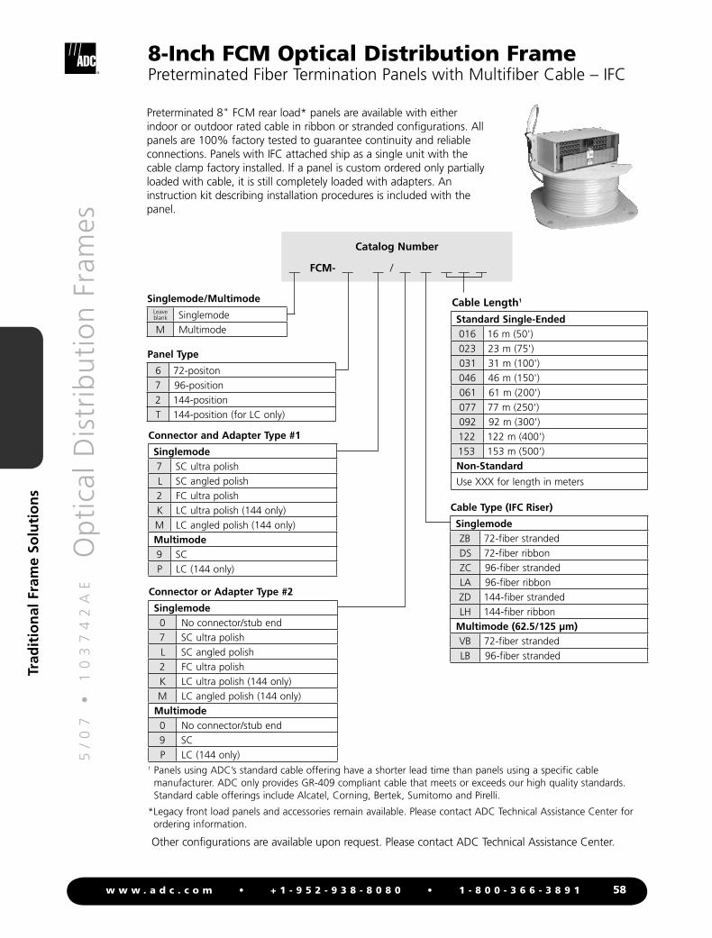
Preterminated 8" FCM rear load* panels are available with either indoor or outdoor rated cable in ribbon or stranded configurations. All panels are 100% factory tested to guarantee continuity and reliable connections. Panels with IFC attached ship as a single unit with the cable clamp factory installed. If a panel is custom ordered only partially loaded with cable, it is still completely loaded with adapters. An instruction kit describing installation procedures is included with the panel.
Catalog Number
__ FCM- __ __ / __ __ __ __ __
1 Panels using ADC’s standard cable offering have a shorter lead time than panels using a specific cable manufacturer. ADC only provides GR-409 compliant cable that meets or exceeds our high quality standards. Standard cable offerings include Alcatel, Corning, Bertek, Sumitomo and Pirelli.
*Legacy front load panels and accessories remain available. Please contact ADC Technical Assistance Center for ordering information.
Other configurations are available upon request. Please contact ADC Technical Assistance Center.
Connector or Adapter Type #2
Singlemode0 No connector/stub end7 SC ultra polishL SC angled polish2 FC ultra polishK LC ultra polish (144 only)M LC angled polish (144 only)
Multimode0 No connector/stub end9 SCP LC (144 only)
Connector and Adapter Type #1
Singlemode7 SC ultra polishL SC angled polish2 FC ultra polishK LC ultra polish (144 only)M LC angled polish (144 only)Multimode9 SCP LC (144 only)
Standard Single-Ended016 16 m (50')023 23 m (75')031 31 m (100')046 46 m (150')061 61 m (200')077 77 m (250')092 92 m (300')122 122 m (400')153 153 m (500')Non-Standard
Use XXX for length in meters
Cable Type (IFC Riser)
SinglemodeZB 72-fiber strandedDS 72-fiber ribbonZC 96-fiber strandedLA 96-fiber ribbonZD 144-fiber strandedLH 144-fiber ribbon
Multimode (62.5/125 μm)VB 72-fiber strandedLB 96-fiber stranded
Cable Length1
Panel Type
6 72-positon7 96-position2 144-positionT 144-position (for LC only)
Singlemode/MultimodeLeaveblank SinglemodeM Multimode

5/
07
•
1
03
74
2A
E
O
pti
cal D
istr
ibu
tio
n F
ram
es
59w w w . a d c . c o m • + 1 - 9 5 2 - 9 3 8 - 8 0 8 0 • 1 - 8 0 0 - 3 6 6 - 3 8 9 1
Trad
itio
nal
Fra
me
Solu
tio
ns
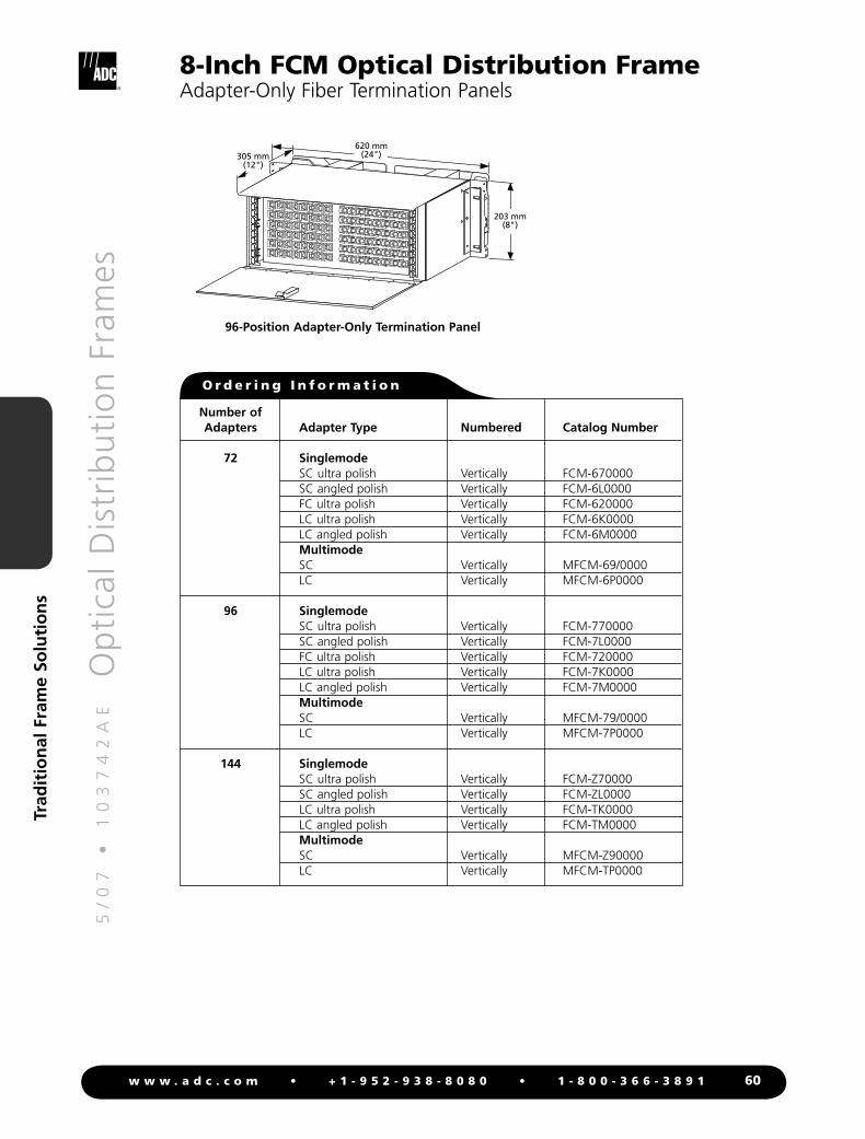
8-Inch FCM Optical Distribution FrameAdapter-Only Fiber Termination Panels
72-Position Termination Panel
620 mm(24")
203 mm(8")
305 mm(12")Ordering information appears on following page.
This panel is designed to be mounted in an ADC rear load* frame equipped with cable management hardware. An accessory mounting kit is required when installing a rear load panel into a 23-inch WECO drilled, unequal flange frame (industry-standard front load frame). Please see page 69 to order this mounting kit. All rear load panels come with rear doors and cable management attached. The FCM panel contains removable angled retainers; angled toward left and right side, ensuring minimum bend radius. Angled retainers are designed for easy removal without use of tool; allowing easy access to back of the adapter/receptacle from the front of the frame. Fanning strips provide organization and cable management at point of entry to the panel. The removable transparent, smoked plastic cover encloses the front of panel while protecting fibers and connectors from disturbance. The designation card identifies each cable and is visible when cover is open or closed.
144-Position Panel(Rear View)
144-Position Panel(Front View)
*Legacy front load panels and accessories remain available. Please contact ADC Technical Assistance Center for ordering information.
5/
07
•
1
03
74
2A
E
O
pti
cal D
istr
ibu
tio
n F
ram
es
60w w w . a d c . c o m • + 1 - 9 5 2 - 9 3 8 - 8 0 8 0 • 1 - 8 0 0 - 3 6 6 - 3 8 9 1
Trad
itio
nal
Fra
me
Solu
tio
ns
Number ofAdapters Adapter Type Numbered Catalog Number
72 Singlemode SC ultra polish Vertically FCM-670000 SC angled polish Vertically FCM-6L0000 FC ultra polish Vertically FCM-620000 LC ultra polish Vertically FCM-6K0000 LC angled polish Vertically FCM-6M0000 Multimode SC Vertically MFCM-69/0000 LC Vertically MFCM-6P0000
96 Singlemode SC ultra polish Vertically FCM-770000 SC angled polish Vertically FCM-7L0000 FC ultra polish Vertically FCM-720000 LC ultra polish Vertically FCM-7K0000 LC angled polish Vertically FCM-7M0000 Multimode SC Vertically MFCM-79/0000 LC Vertically MFCM-7P0000
144 Singlemode SC ultra polish Vertically FCM-Z70000 SC angled polish Vertically FCM-ZL0000 LC ultra polish Vertically FCM-TK0000 LC angled polish Vertically FCM-TM0000 Multimode SC Vertically MFCM-Z90000 LC Vertically MFCM-TP0000
8-Inch FCM Optical Distribution FrameAdapter-Only Fiber Termination Panels
96-Position Adapter-Only Termination Panel
203 mm(8")
620 mm(24")305 mm
(12")
O r d e r i n g I n f o r m a t i o n
5/
07
•
1
03
74
2A
E
O
pti
cal D
istr
ibu
tio
n F
ram
es
61w w w . a d c . c o m • + 1 - 9 5 2 - 9 3 8 - 8 0 8 0 • 1 - 8 0 0 - 3 6 6 - 3 8 9 1
Trad
itio
nal
Fra
me
Solu
tio
ns
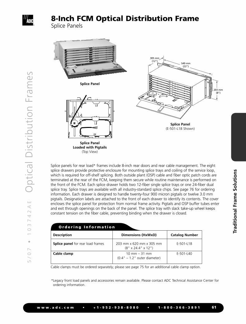
8-Inch FCM Optical Distribution FrameSplice Panels
203 mm(8")
549 mm(22")
305 mm(12")
Splice Panel(E-501-L18 Shown)
Description
Splice panel for rear load frames
Cable clamp
Catalog Number
E-501-L18
E-501-L40
O r d e r i n g I n f o r m a t i o n
Dimensions (HxWxD)
203 mm x 620 mm x 305 mm (8" x 24.4" x 12")
10 mm – 31 mm(0.4" – 1.2" outer diameter)
Splice Panel Loaded with Pigtails
(Top View)
Splice Panel
Splice panels for rear load* frames include 8-inch rear doors and rear cable management. The eight splice drawers provide protective enclosure for mounting splice trays and coiling of the service loop, which is required for off-shelf splicing. Both outside plant (OSP) cable and fiber optic patch cords are terminated at the rear of the FCM, keeping them secure while routine maintenance is performed on the front of the FCM. Each splice drawer holds two 12-fiber single splice trays or one 24-fiber dual splice tray. Splice trays are available with all industry-standard splice chips. See page 76 for ordering information. Each drawer is designed to handle twenty-four 900 micron pigtails or twelve 3.0 mm pigtails. Designation labels are attached to the front of each drawer to identify its contents. The cover encloses the splice panel for protection from normal frame activity. Pigtails and OSP buffer tubes enter and exit through openings on the back of the panel. The splice tray with slack take-up wheel keeps constant tension on the fiber cable, preventing binding when the drawer is closed.
*Legacy front load panels and accessories remain available. Please contact ADC Technical Assistance Center for ordering information.
Cable clamps must be ordered separately; please see page 75 for an additional cable clamp option.

5/
07
•
1
03
74
2A
E
O
pti
cal D
istr
ibu
tio
n F
ram
es
62w w w . a d c . c o m • + 1 - 9 5 2 - 9 3 8 - 8 0 8 0 • 1 - 8 0 0 - 3 6 6 - 3 8 9 1
Trad
itio
nal
Fra
me
Solu
tio
ns
8-Inch FCM Optical Distribution FrameSlack Storage Solutions
Description
48-position fiber storage disk panelfor rear load frames
Catalog Number
E-501-L17
O r d e r i n g I n f o r m a t i o n
Dimensions (HxWxD)
203 mm x 620 mm x 305 mm (8" x 24.4" x 12")
203 mm(8")
620 mm(24")
305 mm(12")
FSD Panel(E-501-L17 Shown)
ADC recommends storage be provided at the FOT for equipment jumpers used in cross-connect applications. See page 66.
Fiber Storage Disk (FSD) PanelThe fiber storage disk (FSD) panel for rear load* frames includes 8-inch rear doors and rear cable management. Panel includes 48 storage disk assemblies, front cover and designation labels. Each panel accommodates 48 separate patch cords (one per disk) and stores three to four meters of 2.0 mm fiber per disk. To maximize the termination density on the frame, ADC recommends that fiber optic terminal (FOT) jumper slack be stored at the FOT frame. See page 66 for storage panel solutions. ADC also recommends use of an interbay management panel to store cross-connect patch cord slack. See page 65 to order.
*Legacy front load panels and accessories remain available. Please contact ADC Technical Assistance Center for ordering information.

5/
07
•
1
03
74
2A
E
O
pti
cal D
istr
ibu
tio
n F
ram
es
63w w w . a d c . c o m • + 1 - 9 5 2 - 9 3 8 - 8 0 8 0 • 1 - 8 0 0 - 3 6 6 - 3 8 9 1
Trad
itio
nal
Fra
me
Solu
tio
ns
8-Inch FCM Optical Distribution FrameSlack Storage Solutions
Cable Management Tray (CMT) Storage PanelThe CMT storage panel includes 8-inch rear doors* and rear cable management. CMT’s are hinged to chassis and swing outward toward to the front. Fibers are routed into and out of the entry point near the hinge. Each CMT holds up to two patch cords, with a total capacity of eight to ten meters of 2.0 mm fiber. A designation strip is attached to the front and is used to identify contents of each tray. To maximize the termination density on the frame, ADC recommends that fiber optic terminal (FOT) jumper slack be stored at the FOT frame. See page 66 for storage panel solutions. ADC also recommends use of an interbay management panel to store cross-connect patch cord slack. See page 65 to order.
203 mm(8")
620 mm(24")
305 mm(12")
CMT Storage Panel(E-501-L16 Shown)
Description
Cable management tray storage panelwith 18 cable management trays and 8" rear door, for rear load frames*
Catalog Number
E-501-L16
O r d e r i n g I n f o r m a t i o n
Dimensions (HxWxD)
203 mm x 620 mm x 305 mm (8" x 24.4" x 12")
ADC recommends storage be provided at the FOT for equipment jumpers used in cross-connect applications. See page 66.
*Legacy front load panels and accessories remain available. Please contact ADC Technical Assistance Center for ordering information.
5/
07
•
1
03
74
2A
E
O
pti
cal D
istr
ibu
tio
n F
ram
es
64w w w . a d c . c o m • + 1 - 9 5 2 - 9 3 8 - 8 0 8 0 • 1 - 8 0 0 - 3 6 6 - 3 8 9 1
Trad
itio
nal
Fra
me
Solu
tio
ns
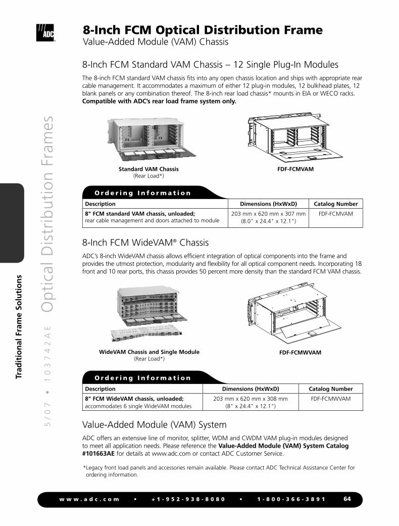
8-Inch FCM Optical Distribution FrameValue-Added Module (VAM) Chassis
Value-Added Module (VAM) SystemADC offers an extensive line of monitor, splitter, WDM and CWDM VAM plug-in modules designed to meet all application needs. Please reference the Value-Added Module (VAM) System Catalog #101663AE for details at www.adc.com or contact ADC Customer Service.
WideVAM Chassis and Single Module(Rear Load*)
O r d e r i n g I n f o r m a t i o n
Description Dimensions (HxWxD) Catalog Number
8" FCM WideVAM chassis, unloaded;accommodates 6 single WideVAM modules
203 mm x 620 mm x 308 mm(8" x 24.4" x 12.1")
FDF-FCMWVAM
FDF-FCMWVAM
8-Inch FCM Standard VAM Chassis – 12 Single Plug-In ModulesThe 8-inch FCM standard VAM chassis fits into any open chassis location and ships with appropriate rear cable management. It accommodates a maximum of either 12 plug-in modules, 12 bulkhead plates, 12 blank panels or any combination thereof. The 8-inch rear load chassis* mounts in EIA or WECO racks. Compatible with ADC’s rear load frame system only.
FDF-FCMVAM
Description Dimensions (HxWxD) Catalog Number
8" FCM standard VAM chassis, unloaded;rear cable management and doors attached to module
203 mm x 620 mm x 307 mm(8.0" x 24.4" x 12.1")
FDF-FCMVAM
O r d e r i n g I n f o r m a t i o n
Standard VAM Chassis(Rear Load*)
*Legacy front load panels and accessories remain available. Please contact ADC Technical Assistance Center for ordering information.
8-Inch FCM WideVAM® ChassisADC’s 8-inch WideVAM chassis allows efficient integration of optical components into the frame and provides the utmost protection, modularity and flexibility for all optical component needs. Incorporating 18 front and 10 rear ports, this chassis provides 50 percent more density than the standard FCM VAM chassis.
5/
07
•
1
03
74
2A
E
O
pti
cal D
istr
ibu
tio
n F
ram
es
65w w w . a d c . c o m • + 1 - 9 5 2 - 9 3 8 - 8 0 8 0 • 1 - 8 0 0 - 3 6 6 - 3 8 9 1
Trad
itio
nal
Fra
me
Solu
tio
ns
8-Inch FCM Optical Distribution FrameFrame Accessories
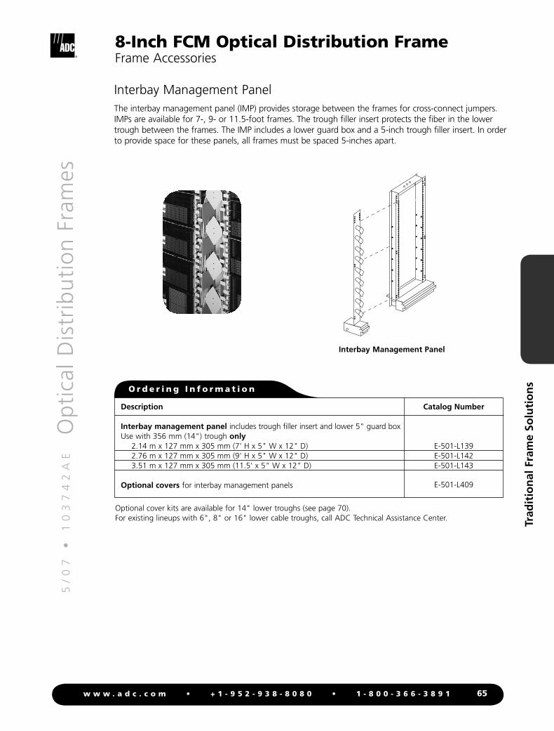
Interbay Management PanelThe interbay management panel (IMP) provides storage between the frames for cross-connect jumpers. IMPs are available for 7-, 9- or 11.5-foot frames. The trough filler insert protects the fiber in the lower trough between the frames. The IMP includes a lower guard box and a 5-inch trough filler insert. In order to provide space for these panels, all frames must be spaced 5-inches apart.
Description
Interbay management panel includes trough filler insert and lower 5" guard boxUse with 356 mm (14") trough only
2.14 m x 127 mm x 305 mm (7' H x 5" W x 12" D)2.76 m x 127 mm x 305 mm (9' H x 5" W x 12" D)3.51 m x 127 mm x 305 mm (11.5' x 5" W x 12" D)
Optional covers for interbay management panels
Catalog Number
E-501-L139E-501-L142E-501-L143
E-501-L409
O r d e r i n g I n f o r m a t i o n
Optional cover kits are available for 14" lower troughs (see page 70).For existing lineups with 6", 8" or 16" lower cable troughs, call ADC Technical Assistance Center.
Interbay Management Panel
5/
07
•
1
03
74
2A
E
O
pti
cal D
istr
ibu
tio
n F
ram
es
66w w w . a d c . c o m • + 1 - 9 5 2 - 9 3 8 - 8 0 8 0 • 1 - 8 0 0 - 3 6 6 - 3 8 9 1
Trad
itio
nal
Fra
me
Solu
tio
ns
8-Inch FCM Optical Distribution FrameFrame Accessories
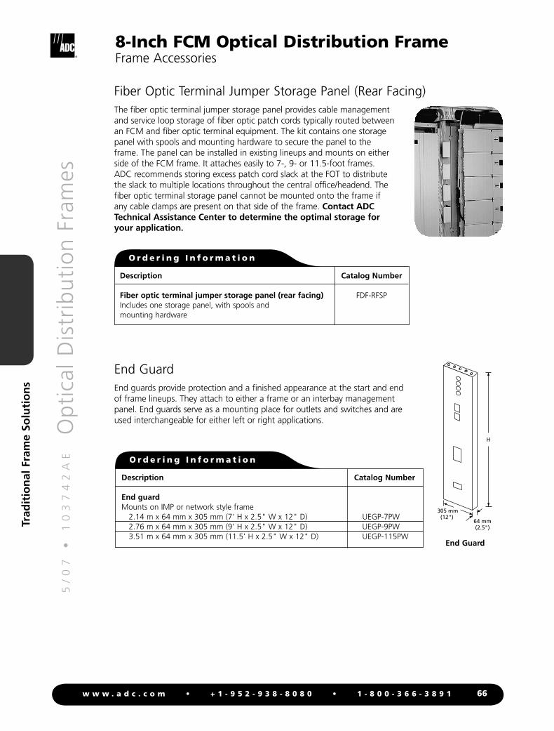
Fiber Optic Terminal Jumper Storage Panel (Rear Facing)The fiber optic terminal jumper storage panel provides cable management and service loop storage of fiber optic patch cords typically routed between an FCM and fiber optic terminal equipment. The kit contains one storage panel with spools and mounting hardware to secure the panel to the frame. The panel can be installed in existing lineups and mounts on either side of the FCM frame. It attaches easily to 7-, 9- or 11.5-foot frames. ADC recommends storing excess patch cord slack at the FOT to distribute the slack to multiple locations throughout the central office/headend. The fiber optic terminal storage panel cannot be mounted onto the frame if any cable clamps are present on that side of the frame. Contact ADC Technical Assistance Center to determine the optimal storage for your application.
Description
Fiber optic terminal jumper storage panel (rear facing)Includes one storage panel, with spools and mounting hardware
Catalog Number
FDF-RFSP
O r d e r i n g I n f o r m a t i o n
End GuardEnd guards provide protection and a finished appearance at the start and end of frame lineups. They attach to either a frame or an interbay management panel. End guards serve as a mounting place for outlets and switches and are used interchangeable for either left or right applications.
305 mm(12")
H
64 mm(2.5")
Description
End guard Mounts on IMP or network style frame 2.14 m x 64 mm x 305 mm (7' H x 2.5" W x 12" D) 2.76 m x 64 mm x 305 mm (9' H x 2.5" W x 12" D) 3.51 m x 64 mm x 305 mm (11.5' H x 2.5" W x 12" D)
Catalog Number
UEGP-7PWUEGP-9PWUEGP-115PW
O r d e r i n g I n f o r m a t i o n
End Guard

5/
07
•
1
03
74
2A
E
O
pti
cal D
istr
ibu
tio
n F
ram
es
67w w w . a d c . c o m • + 1 - 9 5 2 - 9 3 8 - 8 0 8 0 • 1 - 8 0 0 - 3 6 6 - 3 8 9 1
Trad
itio
nal
Fra
me
Solu
tio
ns
8-Inch FCM Optical Distribution FrameFrame Accessories
Guard Box (Underfloor)
Description
Underfloor guard box Rear access only. Used for routing OSP or
IFC cable or patch cords from under floor to the rear of the frame.
Front and rear access. Used for routing OSP, IFC or patch cords from under floor to the rear of the frame and patch cords from under floor to the front of the frame.
Catalog Number
FDF-ACC139
FDF-ACC152
O r d e r i n g I n f o r m a t i o n
Dimensions (HxWxD)
100 mm x 125 mm x 125 mm(3.9" x 4.9" x 4.9")
179 mm x 218 mm x 127 mm(7.1" x 8.6" x 5")
124 mm(4.9")
100 mm(3.9")
125 mm(4.9")
127 mm (5")
99 mm (3.9")
25 mm (1")
218 mm(8.6")
81 mm(3.2")
78 mm(3.1")
Rear Access Underfloor Guard Box (Front View)FDF-ACC139
Front/Rear Access Underfloor Guard Box (Rear View)
FDF-ACC152
Shown Installed Between Network Frames and at End of a Lineup
(Front View)FDF-ACC152
5/
07
•
1
03
74
2A
E
O
pti
cal D
istr
ibu
tio
n F
ram
es
68w w w . a d c . c o m • + 1 - 9 5 2 - 9 3 8 - 8 0 8 0 • 1 - 8 0 0 - 3 6 6 - 3 8 9 1
Trad
itio
nal
Fra
me
Solu
tio
ns
8-Inch FCM Optical Distribution FrameFrame Accessories
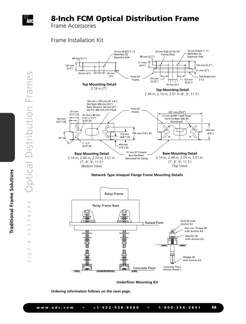
Frame Installation Kit
Front Of Frame
Front OfFrame
459 mm (1.8") (2)
122 mm (4.8") (3)
199 mm (7.8") (2)
102 mm (4.3") (4)
131 mm (5.2") (2)
102 mm x 703 mm (4" x 8") Slot Rack 584 mm (23") Rack (Shown) 102 mm (4") Dia For 483 mm (19") Rack
1" x 3"SLOT (4)
41 mm x 80 mm (1.6" x 3.3")SLOT (2)
51 mm (2")
132 mm (5.2")
68 mm (2.7")
111 mm (4.4")
133 mm (5.25")
16 mm (0.625") -11 Weld Nut (3) Opposite Side
137 mm(5.4")
68 mm (2.7")
76 mm (3") 76 mm (3")
16 mm (0.625") -11 Weld Nut (3) Opposite Side
Top Mounting Detail2.14 m (7') Top Mounting Detail
2.44 m, 2.74 m, 3.51 m (8', 9', 11.5')
20 mm (0.8) (2) On 23"Frames Only
Base Mounting Detail2.14 m, 2.44 m, 2.74 m, 3.51 m
(7', 8', 9', 11.5')(Bottom View)
657 mm (25.9")12 mm (0.495") Half Shear
Form To Near Side 4X(Knockout)
Base Mounting Detail2.14 m, 2.44 m, 2.74 m, 3.51 m
(7', 8', 9', 11.5')(Top View)
244 mm (9.6")
Top Angle Iron2 x 2
51 mm (2") Guard Box Has Been
Removed For Clarity
45° (4)
76 mm (3")
133 mm (5.25")
Network Type Unequal Flange Frame Mounting Details
Relay Frame Base
Relay Frame
Raised Floor
Concrete Floor Concrete FloorAnchor Detail 1
Wedge (4)with Anchor Kit
Washer (4)with Anchor Kit
Hex nut, Torque (4)with Anchor Kit
Stud (4) withAnchor Kit
Underfloor Mounting Kit
Ordering information follows on the next page.

5/
07
•
1
03
74
2A
E
O
pti
cal D
istr
ibu
tio
n F
ram
es
69w w w . a d c . c o m • + 1 - 9 5 2 - 9 3 8 - 8 0 8 0 • 1 - 8 0 0 - 3 6 6 - 3 8 9 1
Trad
itio
nal
Fra
me
Solu
tio
ns
8-Inch FCM Optical Distribution FrameFrame Accessories
Frame Installation Kit
Description
Frame installation kit for 2.14 m (7') frames, includes;- (1) floor mounting kit- (1) top attachment kit for 2.14 m (7') frames- (12) frame tie brackets kits- (1) frame ground kit for 2.14 m (7') frames
Frame installation kit for 2.74 m (9') and 3.51 m (11.5') frames, includes;- (1) floor mounting kit- (1) top attachment kit for 2.74 m (9') and 3.51 m (11.5') frames- (22) frame tie brackets kits- (1) frame ground kit for 2.74 m (9') and 3.51 m (11.5') frames
Universal anchor kit, for all UEF frames includes;- (4) anchor assemblies- (2) universal hold down bars- (8) anchor plate washers- (8) shim plates 2 mm (0.063")- (4) shim plates 3 mm (0.125")
Isolation pad accommodates;- (1) UEF 23" network frame- (2) end guards- (2) interbay management panels
Catalog Number
RINST-DSX7-PW
RINST-DSX9-PW
RINST-FLR
FDF-ISOTEMPLATE
O r d e r i n g I n f o r m a t i o n
Frame installation kits may be used on network frames and are seismic zone 4 rated.

5/
07
•
1
03
74
2A
E
O
pti
cal D
istr
ibu
tio
n F
ram
es
70w w w . a d c . c o m • + 1 - 9 5 2 - 9 3 8 - 8 0 8 0 • 1 - 8 0 0 - 3 6 6 - 3 8 9 1
Trad
itio
nal
Fra
me
Solu
tio
ns
FrontTrough Cover
356 mm (14") UniversalTrough
Filler Trough
FrameInterbayManagementPanel
(Optional coverfor interbaymanage-ment panel.See page TBDfor ordering information)
8-Inch FCM Optical Distribution FrameFrame Accessories
Horizontal Cable TroughLower horizontal cable troughs are always included with fiber frames. They can be purchased separately for special applications.
The upper cable trough is not a standard part of the frame. It should be used in applications in which patch cords need to be brought from the front of the frame to the rear. The upper cable trough is putty white and mounts at the top of the frame. Bend radius limiters are provided on the edges of the trough to maintain minimum bend radius requirements.
356 mm (14") Lower Cable Trough(E-501-L136 Shown)
102 mm (4") Upper Cable Trough(E-501-L514 Shown)
152 mm (6") Lower Cable Trough
(E-501-L73 Shown)
Description
Lower horizontal cable trough152 mm x 584 mm x 127 mm (6"H x 23" W x 5" D)203 mm x 584 mm x 127 mm (8"H x 23" W x 5" D)336 mm x 584 mm x 127 mm (14"H x 23" W x 5" D)406 mm x 584 mm x 127 mm (16"H x 23" W x 5" D)
Upper horizontal cable trough with pass through capability102 mm x 584 mm x 127 mm (4" H x 23" W x 10" D)
Catalog Number
E-501-L73FDF-ACC-LHCTE-501-L136FDF-ACC-LDCT
E-501-L514
O r d e r i n g I n f o r m a t i o n
Description
Cover for 356 mm (14") lower horizontal cable trough; requires modified lower horizontal cable troughs for 203 mm x 584 mm (8" x 23") mounting systems
Catalog Number
FDF-ACC167
O r d e r i n g I n f o r m a t i o n
Cover Kit for Lower Horizontal Cable TroughCover kit offers added protection for patch cords within the lower trough during normal central office use.
Cover Kit
5/
07
•
1
03
74
2A
E
O
pti
cal D
istr
ibu
tio
n F
ram
es
71w w w . a d c . c o m • + 1 - 9 5 2 - 9 3 8 - 8 0 8 0 • 1 - 8 0 0 - 3 6 6 - 3 8 9 1
Trad
itio
nal
Fra
me
Solu
tio
ns
8-Inch FCM Optical Distribution FrameFrame Accessories
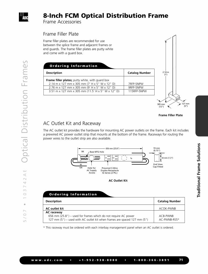
Frame Filler PlateFrame filler plates are recommended for use between the splice frame and adjacent frames or end guards. The frame filler plates are putty white and come with a guard box.
Description
Frame filler plates; putty white, with guard box 2.14 m x 127 mm x 305 mm (7' H x 5" W x 12" D) 2.76 m x 127 mm x 305 mm (9' H x 5" W x 12" D) 3.51 m x 127 mm x 305 mm (11.5' H x 5" W x 12" D)
Catalog Number
7RFP-5NPW 9RFP-5NPW 115RFP-5NPW
O r d e r i n g I n f o r m a t i o n
127 mm (5")
305 mm (12")
2.14 m(7')
AC Outlet Kit and RacewayThe AC outlet kit provides the hardware for mounting AC power outlets on the frame. Each kit includes a prewired AC power outlet strip that mounts at the bottom of the frame. Raceways for routing the power wires to the outlet strip are also available.
End ViewCap Fitted
BK
WGN Hole for
AC Supply Access
Prewired 3-WireDuplex Receptacle
IG Series (2 Pls.)
Base MTG Hole
656 mm (25.8")
33 mm (1.3")
19 mm (0.75")
AC Outlet Kit
Description
AC outlet kitAC raceway 656 mm (25.8") – used for frames which do not require AC power 127 mm (5") – used with AC outlet kit when frames are spaced 127 mm (5")
Catalog Number
ACOK-PWNB
ACB-PWNB AC-PWNB-RS5*
O r d e r i n g I n f o r m a t i o n
* This raceway must be ordered with each interbay management panel when an AC outlet is ordered.
Frame Filler Plate
5/
07
•
1
03
74
2A
E
O
pti
cal D
istr
ibu
tio
n F
ram
es
72w w w . a d c . c o m • + 1 - 9 5 2 - 9 3 8 - 8 0 8 0 • 1 - 8 0 0 - 3 6 6 - 3 8 9 1
Trad
itio
nal
Fra
me
Solu
tio
ns
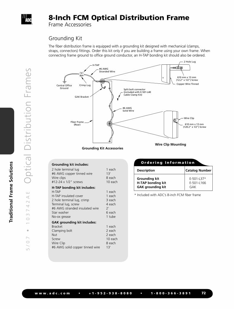
Grounding KitThe fiber distribution frame is equipped with a grounding kit designed with mechanical (clamps, straps, connectors) fittings. Order this kit only if you are building a frame using your own frame. When connecting frame ground to office ground conductor, an H-TAP bonding kit should also be ordered.
Grounding Kit Accessories
Wire Clip
2 Hole Lug
610 mm x 13 mm (12.2" x 1/2") Screw
610 mm x 13 mm (120.2" x 1/2") Screw
Copper Wire TinnedCentral Office
Ground
GAK Bracket
Crimp Lug
Split bolt connector(included with E-501-L40Cable Clamp Kit)
H-TAP
#6 AWGStranded Wire
#6 AWGSolid Wire
Fiber Frame(Rear)
Wire Clip Mounting
Description
Grounding kitH-TAP bonding kitGAK grounding kit
Catalog Number
E-501-L37*E-501-L166GAK
* Included with ADC’s 8-inch FCM fiber frame
Grounding kit includes:2 hole terminal lug 1 each #6 AWG copper tinned wire 13'Wire clips 8 each#12-24 x 1/2" screws 10 each
H-TAP bonding kit includes:H-TAP 1 eachH-TAP insulated cover 1 each2 hole terminal lug, crimp 3 eachTerminal lug, screw 4 each#6 AWG stranded insulated wire 2'Star washer 6 eachNo-ox grease 1 tube
GAK grounding kit includes:Bracket 1 eachClamping bolt 2 eachNut 2 eachScrew 10 eachWire Clip 8 each#6 AWG solid copper tinned wire 13'
8-Inch FCM Optical Distribution FrameFrame Accessories
O r d e r i n g I n f o r m a t i o n

5/
07
•
1
03
74
2A
E
O
pti
cal D
istr
ibu
tio
n F
ram
es
73w w w . a d c . c o m • + 1 - 9 5 2 - 9 3 8 - 8 0 8 0 • 1 - 8 0 0 - 3 6 6 - 3 8 9 1
Trad
itio
nal
Fra
me
Solu
tio
ns
Communications PanelThe COMP-21 communications panel features soft touch key access to nine dial lines (POTS or 1A2 Key Telephone) or seven dial lines and any combination of two office intercom and signal lines along with hold, conference and on-hook features. (The hold feature only functions with 1A2 key telephone.)
In addition to the features on the COMP-21, the COMP-11 is equipped with a remote head-set jack circuit. This panel has nine soft touch keys that permit the remote headset jacks to be connected to any telephone line key position while allowing the panel to be free for use on other telephone or intercom lines.
COMP-11 Communications Panel with Remote Headset Jack Circuit
and Retractable Writing Shelf
COMP-21 Communications Panelwith Retractable Writing Shelf
1 2 3 4 5 6 7 8 9
1 2 3 4 5 6 7 8 9HOLDCOMPON
HDDK
HDST -48V -48V
REMOTEHEADSET
538 mm (21")585 mm (21.6")
127 mm (5")
196 mm (7.7")
1 2 3 4 5 6 7 8 9
1 2 3 4 5 6 7 8 9HOLDCOMPON
HDDK
HDST -48V -48V
REMOTEHEADSET
538 mm (21")585 mm (21.6")
127 mm (5")
196 mm (7.7")
Description
COMP-11 communications panel;includes mounting brackets and remote head set jack
With retractable writing shelfWithout retractable writing shelf
COMP-21 communications panel; includes mounting bracketsWith retractable writing shelfWithout retractable writing shelf
Headset with 3.66 m (12') coil cordHandset with communications cordHandset with holderRear 203 mm (8") doors and fanning triangles – used when communications panel is mounted in rear load frame
Catalog Number
E-501-L140E-501-L175
E-501-L141E-501-L123
COMP-HDSCOMP-HNDSKITCOMP-HNR-PFDF-ACC050
O r d e r i n g I n f o r m a t i o n
Headsets and a handset holder are not provided with the communication panels and must be ordered separately. For information on daisy-chaining communications panels contact ADC Technical Assistance Center.
8-Inch FCM Optical Distribution FrameFrame Accessories
5/
07
•
1
03
74
2A
E
O
pti
cal D
istr
ibu
tio
n F
ram
es
74w w w . a d c . c o m • + 1 - 9 5 2 - 9 3 8 - 8 0 8 0 • 1 - 8 0 0 - 3 6 6 - 3 8 9 1
Trad
itio
nal
Fra
me
Solu
tio
ns
8-Inch FCM Optical Distribution FramePanel Accessories
Vertical Cable Guide (VCG) KitThere are times when a single panel must be mounted in a frame without a cable management system. An individual 8-inch VCG kit is available to mount FCM panels into a network style or unequal flange 23-inch frame.
Description
VCG kitContains two 203 mm (8") front vertical cable guides and screws for mounting the rear load FCM into a frame
Catalog Number
FDF-ACC145
O r d e r i n g I n f o r m a t i o n
Blank PanelThe blank panel occupies one panel space in either a front load or rear load frame.
Description
Blank panel, 203 mm (8") H
Catalog Number
E-501-L39
O r d e r i n g I n f o r m a t i o n
5/
07
•
1
03
74
2A
E
O
pti
cal D
istr
ibu
tio
n F
ram
es
75w w w . a d c . c o m • + 1 - 9 5 2 - 9 3 8 - 8 0 8 0 • 1 - 8 0 0 - 3 6 6 - 3 8 9 1
Trad
itio
nal
Fra
me
Solu
tio
ns
8-Inch FCM Optical Distribution FramePanel Accessories
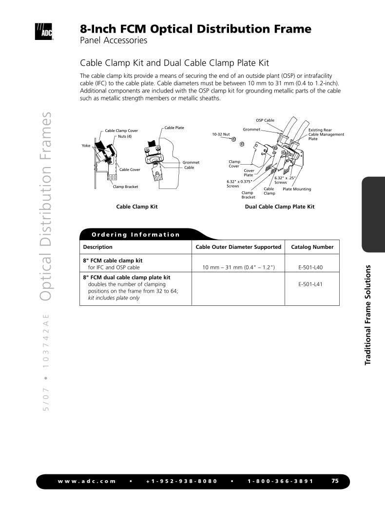
Cable Clamp Kit and Dual Cable Clamp Plate KitThe cable clamp kits provide a means of securing the end of an outside plant (OSP) or intrafacility cable (IFC) to the cable plate. Cable diameters must be between 10 mm to 31 mm (0.4 to 1.2-inch). Additional components are included with the OSP clamp kit for grounding metallic parts of the cable such as metallic strength members or metallic sheaths.
6.32" x 0.375"Screws
6.32" x .25"Screws
10-32 NutExisting RearCable ManagementPlate
Plate MountingCableClampClamp
Bracket
ClampCover
CoverPlate
OSP Cable
Grommet
Dual Cable Clamp Plate Kit
Cable Clamp CoverNuts (4)
Yoke
Cable Cover
Clamp Bracket
Cable Plate
GrommetCable
Cable Clamp Kit
Description
8" FCM cable clamp kit for IFC and OSP cable
8" FCM dual cable clamp plate kit doubles the number of clamping
positions on the frame from 32 to 64; kit includes plate only
Catalog Number
E-501-L40
E-501-L41
O r d e r i n g I n f o r m a t i o n
Cable Outer Diameter Supported
10 mm – 31 mm (0.4" – 1.2")
5/
07
•
1
03
74
2A
E
O
pti
cal D
istr
ibu
tio
n F
ram
es
76w w w . a d c . c o m • + 1 - 9 5 2 - 9 3 8 - 8 0 8 0 • 1 - 8 0 0 - 3 6 6 - 3 8 9 1
Trad
itio
nal
Fra
me
Solu
tio
ns
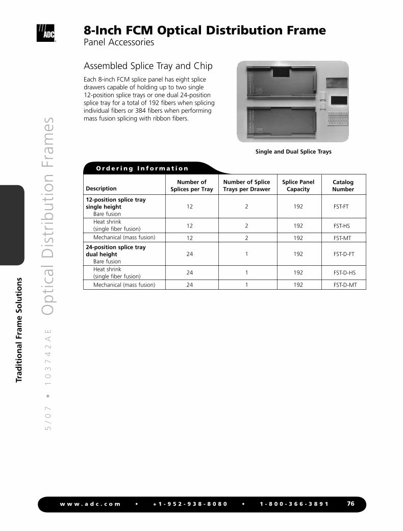
Assembled Splice Tray and ChipEach 8-inch FCM splice panel has eight splice drawers capable of holding up to two single 12-position splice trays or one dual 24-position splice tray for a total of 192 fibers when splicing individual fibers or 384 fibers when performing mass fusion splicing with ribbon fibers.
Single and Dual Splice Trays
Description
12-position splice traysingle height
Bare fusionHeat shrink (single fiber fusion)
Mechanical (mass fusion)
24-position splice tray dual height
Bare fusionHeat shrink (single fiber fusion)
Mechanical (mass fusion)
Splice Panel Capacity
192
192
192
192
192
192
Number of Splice Trays per Drawer
2
2
2
1
1
1
Number of Splices per Tray
12
12
12
24
24
24
CatalogNumber
FST-FT
FST-HS
FST-MT
FST-D-FT
FST-D-HS
FST-D-MT
O r d e r i n g I n f o r m a t i o n
8-Inch FCM Optical Distribution FramePanel Accessories
5/
07
•
1
03
74
2A
E
O
pti
cal D
istr
ibu
tio
n F
ram
es
77w w w . a d c . c o m • + 1 - 9 5 2 - 9 3 8 - 8 0 8 0 • 1 - 8 0 0 - 3 6 6 - 3 8 9 1
Trad
itio
nal
Fra
me
Solu
tio
ns
8-Inch FCM Optical Distribution FramePanel Accessories
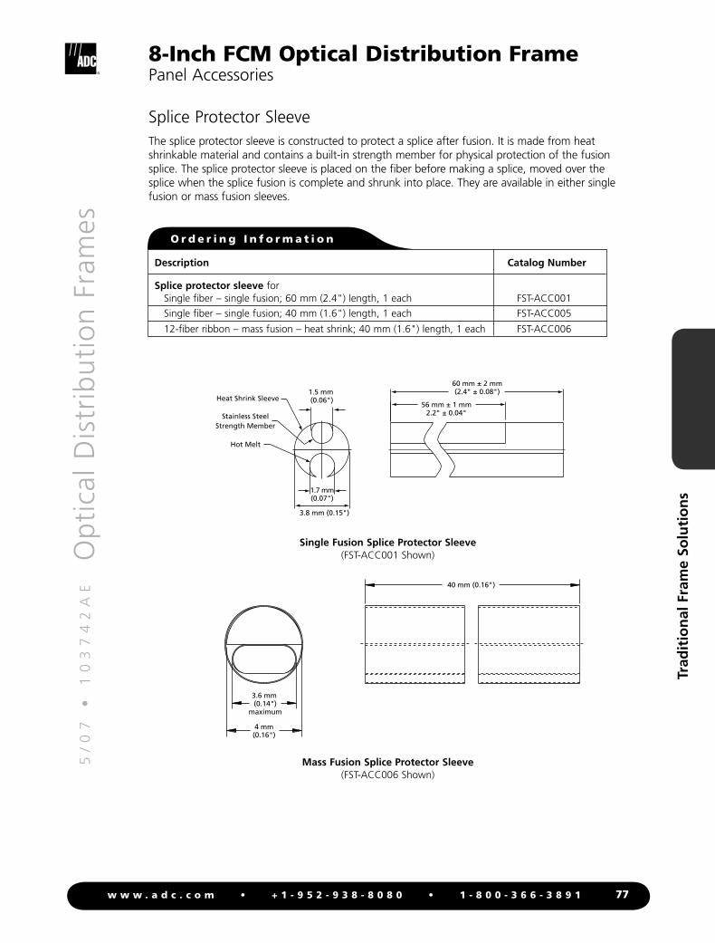
Splice Protector SleeveThe splice protector sleeve is constructed to protect a splice after fusion. It is made from heat shrinkable material and contains a built-in strength member for physical protection of the fusion splice. The splice protector sleeve is placed on the fiber before making a splice, moved over the splice when the splice fusion is complete and shrunk into place. They are available in either single fusion or mass fusion sleeves.
1.7 mm(0.07")
1.5 mm (0.06")
3.8 mm (0.15")
60 mm ± 2 mm(2.4" ± 0.08")
56 mm ± 1 mm2.2" ± 0.04"
Heat Shrink Sleeve
Hot Melt
Stainless SteelStrength Member
3.6 mm (0.14")
maximum
40 mm (0.16")
4 mm (0.16")
Mass Fusion Splice Protector Sleeve(FST-ACC006 Shown)
Single Fusion Splice Protector Sleeve(FST-ACC001 Shown)
Description
Splice protector sleeve for Single fiber – single fusion; 60 mm (2.4") length, 1 each
Single fiber – single fusion; 40 mm (1.6") length, 1 each 12-fiber ribbon – mass fusion – heat shrink; 40 mm (1.6") length, 1 each
Catalog Number
FST-ACC001
FST-ACC005
FST-ACC006
O r d e r i n g I n f o r m a t i o n

5/
07
•
1
03
74
2A
E
O
pti
cal D
istr
ibu
tio
n F
ram
es
78w w w . a d c . c o m • + 1 - 9 5 2 - 9 3 8 - 8 0 8 0 • 1 - 8 0 0 - 3 6 6 - 3 8 9 1
Trad
itio
nal
Fra
me
Solu
tio
ns
Standard Cross-Connect Patch Cord Lengths
For recommended cross-connect methods, refer to FCM user manual ADCP-90-140. For installation instructions for the 8-inch FCM, refer to user manual ADCP-90-113.
8-Inch FCM Optical Distribution FrameFrame Accessories
Ordering Information for Patch Cords and AttenuatorsADC offers a comprehensive line of cable assembly and accessory products including patch cords, IFC assemblies, attenuators, FasTerm® connectors and adapters to meet the demanding needs of today’s network. Please refer to the Fiber Cable Assemblies Catalog #102880AE at www.adc.com for more detailed information. For your convenience, ordering information for patch cords and attenuators can also be found on pages 122–127.
Number of FramesApproximate
Patch Cord Length Meters (Feet)
1 5 m (16.4')
2 6 m (19.7')
3 6 m (19.7')
4 7 m (23')
5 8 m (26.2')
6 9 m (29.5')