Embed Size (px)
Citation preview

78-18106-01
C H A P T E R 4
Optical CardsNote The terms "Unidirectional Path Switched Ring" and "UPSR" may appear in Cisco literature. These terms do not refer to using Cisco ONS 15xxx products in a unidirectional path switched ring configuration. Rather, these terms, as well as "Path Protected Mesh Network" and "PPMN," refer generally to Cisco's path protection feature, which may be used in any topological network configuration. Cisco does not recommend using its path protection feature in any particular topological network configuration.
This chapter describes the Cisco ONS 15454 optical card features and functions. It includes descriptions, hardware specifications, and block diagrams for each optical card. For installation and card turn-up procedures, refer to the Cisco ONS 15454 Procedure Guide.
Chapter topics include:
• 4.1 Optical Card Overview, page 4-2
• 4.2 OC3 IR 4/STM1 SH 1310 Card, page 4-6
• 4.3 OC3 IR/STM1 SH 1310-8 Card, page 4-8
• 4.4 OC12 IR/STM4 SH 1310 Card, page 4-9
• 4.5 OC12 LR/STM4 LH 1310 Card, page 4-11
• 4.6 OC12 LR/STM4 LH 1550 Card, page 4-13
• 4.7 OC12 IR/STM4 SH 1310-4 Card, page 4-15
• 4.8 OC48 IR 1310 Card, page 4-17
• 4.9 OC48 LR 1550 Card, page 4-19
• 4.10 OC48 IR/STM16 SH AS 1310 Card, page 4-21
• 4.11 OC48 LR/STM16 LH AS 1550 Card, page 4-23
• 4.12 OC48 ELR/STM16 EH 100 GHz Cards, page 4-25
• 4.13 OC48 ELR 200 GHz Cards, page 4-27
• 4.14 OC192 SR/STM64 IO 1310 Card, page 4-29
• 4.15 OC192 IR/STM64 SH 1550 Card, page 4-31
• 4.16 OC192 LR/STM64 LH 1550 Card, page 4-33
• 4.17 OC192 LR/STM64 LH ITU 15xx.xx Card, page 4-38
• 4.18 15454_MRC-12 Multirate Card, page 4-41
• 4.19 MRC-2.5G-4 Multirate Card, page 4-46
4-1Cisco ONS 15454 Reference Manual, R8.5

Chapter 4 Optical Cards4.1 Optical Card Overview
• 4.20 OC192SR1/STM64IO Short Reach and OC192/STM64 Any Reach Cards, page 4-50
• 4.21 Optical Card SFPs and XFPs, page 4-52
4.1 Optical Card OverviewEach card is marked with a symbol that corresponds to a slot (or slots) on the ONS 15454 shelf assembly. The cards are then installed into slots displaying the same symbols. See the “1.17 Cards and Slots” section on page 1-71 for a list of slots and symbols.
4.1.1 Card SummaryTable 4-1 lists the Cisco ONS 15454 optical cards.
Table 4-1 Optical Cards for the ONS 15454
Card Port Description For Additional Information...
OC3 IR 4 SH 1310 The OC3 IR 4 SH 1310 card provides four intermediate- or short-range OC-3 ports and operates at 1310 nm.
Note The OC3 IR 4 SH 1310 and OC3 IR 4/STM1 SH 1310 cards are functionally the same.
See the “4.2 OC3 IR 4/STM1 SH 1310 Card” section on page 4-6.
OC3 IR 4/ STM1 SH 1310
The OC3 IR 4/STM1 SH 1310 card provides four intermediate- or short-range OC-3 ports and operates at 1310 nm.
See the “4.2 OC3 IR 4/STM1 SH 1310 Card” section on page 4-6.
OC3 IR/ STM1 SH 1310-8
The OC3 IR/STM1 SH 1310-8 card provides eight intermediate- or short-range OC-3 ports and operates at 1310 nm.
See the “4.3 OC3 IR/STM1 SH 1310-8 Card” section on page 4-8.
OC12 IR 1310 The OC12 IR 1310 card provides one intermediate- or short-range OC-12 port and operates at 1310 nm.
Note The OC12 IR 1310 and OC12/STM4 SH 1310 cards are functionally the same.
See the “4.4 OC12 IR/STM4 SH 1310 Card” section on page 4-9.
OC12 IR/STM4 SH 1310
The OC12 IR/STM4 SH 1310 card provides one intermediate- or short-range OC-12 port and operates at 1310 nm.
See the “4.4 OC12 IR/STM4 SH 1310 Card” section on page 4-9.
OC12 LR 1310 The OC12 LR 1310 card provides one long-range OC-12 port and operates at 1310 nm.
Note The OC12 LR 1310 and OC12 LR/STM4 LH 1310 cards are functionally the same.
See the “4.5 OC12 LR/STM4 LH 1310 Card” section on page 4-11.
OC12 LR/STM4 LH 1310
The OC12 LR/STM4 LH 1310 card provides one long-range OC-12 port and operates at 1310 nm.
See the “4.5 OC12 LR/STM4 LH 1310 Card” section on page 4-11.
OC12 LR 1550 The OC12 LR 1550 card provides one long-range OC-12 port and operates at 1550 nm.
Note The OC12 LR 1550 and OC12 LR/STM4 LH 1550 cards are functionally the same.
See the “4.6 OC12 LR/STM4 LH 1550 Card” section on page 4-13.
4-2Cisco ONS 15454 Reference Manual, R8.5
78-18106-01

Chapter 4 Optical Cards4.1.1 Card Summary
OC12 LR/STM4 LH 1550
The OC12 LR/STM4 LH 1550 card provides one long-range OC-12 port and operates at 1550 nm.
See the “4.6 OC12 LR/STM4 LH 1550 Card” section on page 4-13.
OC12 IR/STM4 SH 1310-4
The OC12 IR/STM4 SH 1310-4 card provides four intermediate- or short-range OC-12 ports and operates at 1310 nm.
See the “4.7 OC12 IR/STM4 SH 1310-4 Card” section on page 4-15.
OC48 IR 1310 The OC48 IR 1310 card provides one intermediate-range OC-48 port and operates at 1310 nm.
See the “4.8 OC48 IR 1310 Card” section on page 4-17.
OC48 LR 1550 The OC48 LR 1550 card provides one long-range OC-48 port and operates at 1550 nm.
See the “4.9 OC48 LR 1550 Card” section on page 4-19.
OC48 IR/STM16 SH AS 1310
The OC48 IR/STM16 SH AS 1310 card provides one intermediate- or short-range OC-48 port at 1310 nm.
See the “4.10 OC48 IR/STM16 SH AS 1310 Card” section on page 4-21.
OC48 LR/STM16 LH AS 1550
The OC48 LR/STM16 LH AS 1550 card provides one long-range OC-48 port at 1550 nm.
See the “4.11 OC48 LR/STM16 LH AS 1550 Card” section on page 4-23.
OC48 ELR/STM16 EH 100 GHz
The OC48 ELR/STM16 EH 100 GHz card provides one long-range (enhanced) OC-48 port and operates in Slot 5, 6, 12, or 13. This card is available in 18 different wavelengths (9 in the blue band and 9 in the red band) in the 1550-nm range, every second wavelength in the ITU grid for 100-GHz spacing dense wavelength division multiplexing (DWDM).
See the “4.12 OC48 ELR/STM16 EH 100 GHz Cards” section on page 4-25.
OC48 ELR 200 GHz
The OC48 ELR 200 GHz card provides one long-range (enhanced) OC-48 port and operates in Slot 5, 6, 12, or 13. This card is available in 18 different wavelengths (9 in the blue band and 9 in the red band) in the 1550-nm range, every fourth wavelength in the ITU grid for 200-GHz spacing DWDM.
See the “4.13 OC48 ELR 200 GHz Cards” section on page 4-27.
OC192 SR/STM64 IO 1310
The OC192 SR/STM64 IO 1310 card provides one intra-office-haul OC-192 port at 1310 nm.
See the “4.14 OC192 SR/STM64 IO 1310 Card” section on page 4-29.
OC192 IR/STM64 SH 1550
The OC192 IR/STM64 SH 1550 card provides one intermediate-range OC-192 port at 1550 nm.
See the “4.15 OC192 IR/STM64 SH 1550 Card” section on page 4-31.
OC192 LR/STM64 LH 1550
The OC192 LR/STM64 LH 1550 card provides one long-range OC-192 port at 1550 nm.
See the “4.16 OC192 LR/STM64 LH 1550 Card” section on page 4-33.
OC192 LR/ STM64 LH ITU 15xx.xx
The OC192 LR/STM64 LH ITU 15xx.xx card provides one extended long-range OC-192 port. This card is available in multiple wavelengths in the 1550-nm range of the ITU grid for 100-GHz-spaced DWDM.
See the “4.17 OC192 LR/STM64 LH ITU 15xx.xx Card” section on page 4-38.
Table 4-1 Optical Cards for the ONS 15454 (continued)
Card Port Description For Additional Information...
4-3Cisco ONS 15454 Reference Manual, R8.5
78-18106-01

Chapter 4 Optical Cards4.1.2 Card Compatibility
Note The Cisco OC3 IR/STM1 SH, OC12 IR/STM4 SH, and OC48 IR/STM16 SH interface optics, all working at 1310 nm, are optimized for the most widely used SMF-28 fiber, available from many suppliers.
Corning MetroCor fiber is optimized for optical interfaces that transmit at 1550 nm or in the C and L DWDM windows, and targets interfaces with higher dispersion tolerances than those found in OC3 IR/STM1 SH, OC12 IR/STM4 SH, and OC48 IR/STM16 SH interface optics. If you are using Corning MetroCor fiber, OC3 IR/STM1 SH, OC12 IR/STM4 SH, and OC48 IR/STM16 SH interface optics become dispersion limited before they become attenuation limited. In this case, consider using OC12 LR/STM4 LH and OC48 LR/STM16 LH cards instead of OC12 IR/STM4 SH and OC48 IR/STM16 SH cards.
With all fiber types, network planners/engineers should review the relative fiber type and optics specifications to determine attenuation, dispersion, and other characteristics to ensure appropriate deployment.
4.1.2 Card CompatibilityTable 4-2 lists the CTC software compatibility for each optical card. See Table 2-5 on page 2-4 for a list of cross-connect cards that are compatible with each optical card.
Note “Yes” indicates that this card is fully or partially supported by the indicated software release. Refer to the individual card reference section for more information about software limitations for this card.
15454_MRC-12 The 15454_MRC-12 card provides up to twelve OC-3 or OC-12 ports, or up to four OC-48 ports. The card operates in Slots 1 to 6 and 12 to 17.
See the “4.18 15454_MRC-12 Multirate Card” section on page 4-41.
MRC-2.5G-4 The MRC-2.5G-4 card provides up to four OC-3/STM-1 or OC-12/STM-4 ports, or one OC-48/STM-16 ports. The card operates in Slots 1 to 6 and 12 to 17.
See the “4.19 MRC-2.5G-4 Multirate Card” section on page 4-46.
OC192SR1/STM64IO Short Reach and OC192/STM64 Any Reach1
The OC192SR1/STM64IO Short Reach and OC192/STM64 Any Reach cards each provide a single OC-192/STM-64 interface capable of operating with SR-1, IR-2, and LR-2 XFP modules (depending on the card) at 1310 nm and 1550 nm. The cards operate in Slot 5, 6, 12, or 13 with the XC10G and XC-VXC-10G cards.
See the “4.20 OC192SR1/STM64IO Short Reach and OC192/STM64 Any Reach Cards” section on page 4-50.
1. In the Cisco Transport Controller (CTC) GUI, these cards are known as OC192-XFP.
Table 4-1 Optical Cards for the ONS 15454 (continued)
Card Port Description For Additional Information...
4-4Cisco ONS 15454 Reference Manual, R8.5
78-18106-01

Chapter 4 Optical Cards4.1.2 Card Compatibility
Table 4-2 Optical Card Software Release Compatibility
Optical Card R3.3 R3.4 R4.0 R4.1 R4.51
1. DWDM-only release.
R4.6 R4.71 R5.0 R6.0 R7.0 R7.2 R8.0 8.5
OC3 IR 4 1310 Yes Yes Yes Yes — Yes — Yes Yes Yes Yes Yes Yes
OC3 IR 4/STM1 SH 1310 Yes Yes Yes Yes — Yes — Yes Yes Yes Yes Yes Yes
OC3 IR /STM1 SH 1310-8 — — Yes Yes — Yes — Yes Yes Yes Yes Yes Yes
OC12 IR/STM4 SH 1310 Yes Yes Yes Yes — Yes — Yes Yes Yes Yes Yes Yes
OC12 IR 1310 Yes Yes Yes Yes — Yes — Yes Yes Yes Yes Yes Yes
OC12 LR 1310 Yes Yes Yes Yes — Yes — Yes Yes Yes Yes Yes Yes
OC12 LR 1550 Yes Yes Yes Yes — Yes — Yes Yes Yes Yes Yes Yes
OC12 LR/STM4 LH 1310 Yes Yes Yes Yes — Yes — Yes Yes Yes Yes Yes Yes
OC12 LR/STM4 LH 1550 Yes Yes Yes Yes — Yes — Yes Yes Yes Yes Yes Yes
OC12 IR/STM4 SH 1310-4 Yes Yes Yes Yes — Yes — Yes Yes Yes Yes Yes Yes
OC48 IR 1310 Yes Yes Yes Yes — Yes — Yes Yes Yes Yes Yes Yes
OC48 LR 1550 Yes Yes Yes Yes — Yes — Yes Yes Yes Yes Yes Yes
OC48 IR/STM16 SH AS 13102
2. To enable OC-192 and OC-48 any-slot card operation, use the XC10G or XC-VXC-10G card, the TCC+/TCC2/TCC2P card, Software R3.1 or later, and the 15454-SA-ANSI or 154545-SA-HD shelf assembly. Note that the TCC+ card is not compatible with Software 4.5 or later.
Yes Yes Yes Yes — Yes — Yes Yes Yes Yes Yes Yes
OC48 LR/STM16 LH AS 15503
3. To enable OC-192 and OC-48 any-slot card operation, use the XC10G or XC-VXC-10G card, the TCC+/TCC2/TCC2P card, Software R3.1 or later, and the 15454-SA-ANSI or 154545-SA-HD shelf assembly. Note that the TCC+ card is not compatible with Software 4.5 or later.
Yes Yes Yes Yes — Yes — Yes Yes Yes Yes Yes Yes
OC48 ELR/STM16 EH 100 GHz Yes Yes Yes Yes — Yes — Yes Yes Yes Yes Yes Yes
OC48 ELR 200 GHz Yes Yes Yes Yes — Yes — Yes Yes Yes Yes Yes Yes
OC192 SR/STM64 IO 1310 — — Yes Yes — Yes — Yes Yes Yes Yes Yes Yes
OC192 IR/STM64 SH 1550 — — Yes Yes — Yes — Yes Yes Yes Yes Yes Yes
OC192 LR/STM64 LH 1550(15454-OC192LR1550)
Yes Yes Yes Yes — Yes — Yes Yes Yes Yes Yes Yes
OC192 LR/STM64 LH 1550(15454-OC192-LR2)
— — Yes Yes — Yes — Yes Yes Yes Yes Yes Yes
OC192 LR/STM64 LH ITU 15xx.xx — — Yes Yes — Yes — Yes Yes Yes Yes Yes Yes
15454_MRC-12 — — — — — — — — Yes Yes Yes Yes Yes
MRC-2.5G-4 — — — — — — — — — — — Yes Yes
OC192SR1/STM64IO Short Reach and OC192/STM64 Any Reach4
4. These cards are designated as OC192-XFP in CTC.
— — — — — — — — Yes Yes Yes Yes Yes
4-5Cisco ONS 15454 Reference Manual, R8.5
78-18106-01

Chapter 4 Optical Cards4.2 OC3 IR 4/STM1 SH 1310 Card
4.2 OC3 IR 4/STM1 SH 1310 Card
Note For hardware specifications, see the “A.6.1 OC3 IR 4/STM1 SH 1310 Card Specifications” section on page A-28. See Table 4-2 on page 4-5 for optical card compatibility.
The OC3 IR 4/STM1 SH 1310 card provides four intermediate or short range SONET/SDH OC-3 ports compliant with ITU-T G.707, ITU-T G.957, and Telcordia GR-253-CORE. Each port operates at 155.52 Mbps over a single-mode fiber span. The card supports Virtual Tributary (VT), nonconcatenated (STS-1), or concatenated (STS-1 or STS-3c) payloads. Figure 4-1 shows the OC3 IR 4/STM1 SH 1310 faceplate and a block diagram of the card.
Warning The laser is on when the optical card is booted. The port does not have to be in service for the laser to be on. Statement 293
Note The OC3 IR 4 SH 1310 and OC3 IR 4/STM1 SH 1310 cards are functionally the same.
Figure 4-1 OC3 IR 4/STM1 SH 1310 Faceplate and Block Diagram
uP bus
uP
Flash RAM
BTCASIC
Backplane
STS-12
STS-12/STS-3
Mux/Demux
OpticalTransceiver
OpticalTransceiver
OpticalTransceiver
OpticalTransceiver
STS-3termination/
framing
STS-3termination/
framing
STS-3termination/
framing
STS-3termination/
framing
OC-3
6135
2
133678 12931
Tx
Rx
2
Tx
Rx
4
Tx
Rx
3
Tx
Rx
FAIL
ACT
SF
OC3IR4STM1SH1310
4-6Cisco ONS 15454 Reference Manual, R8.5
78-18106-01

Chapter 4 Optical Cards4.2.1 OC3 IR 4/STM1 SH 1310 Card-Level Indicators
You can install the OC3 IR 4/STM1 SH 1310 card in Slots 1 to 6 and 12 to 17. The card can be provisioned as part of a path protection or a linear add/drop multiplexer (ADM) configuration. Each interface features a 1310-nm laser and contains a transmit and receive connector (labeled) on the card faceplate. The card uses SC connectors.
The OC3 IR 4/STM1 SH 1310 card supports 1+1 unidirectional or bidirectional protection switching. You can provision protection on a per port basis.
The OC3 IR 4/STM1 SH 1310 card detects loss of signal (LOS), loss of frame (LOF), loss of pointer (LOP), line-layer alarm indication signal (AIS-L), and line-layer remote defect indication (RDI-L) conditions. Refer to the Cisco ONS 15454 Troubleshooting Guide for a description of these conditions. The card also counts section and line bit interleaved parity (BIP) errors.
To enable automatic protection switching (APS), the OC3 IR 4/STM1 SH 1310 card extracts the K1 and K2 bytes from the SONET overhead to perform appropriate protection switches. The data communication channel/general communication channel (DCC/GCC) bytes are forwarded to the TCC2/TCC2P card, which terminates the DCC/GCC.
4.2.1 OC3 IR 4/STM1 SH 1310 Card-Level IndicatorsTable 4-3 describes the three card-level LED indicators on the OC3 IR 4/STM1 SH 1310 card.
4.2.2 OC3 IR 4/STM1 SH 1310 Port-Level IndicatorsEight bicolor LEDs show the status per port. The LEDs are green if the port is available to carry traffic, is provisioned as in-service, and is part of a protection group, in the active mode. You can find the status of the four card ports by using the LCD screen on the ONS 15454 fan-tray assembly. Use the LCD to view the status of any port or card slot; the screen displays the number and severity of alarms for a given port or slot. Refer to the Cisco ONS 15454 Troubleshooting Guide for a complete description of the alarm messages.
Table 4-3 OC3 IR 4/STM1 SH 1310 Card-Level Indicators
Card-Level Indicators Description
Red FAIL LED The red FAIL LED indicates that the card’s processor is not ready. This LED is on during reset. The FAIL LED flashes during the boot process. Replace the card if the red FAIL LED persists.
Green ACT LED The green ACT LED indicates that the card is carrying traffic or is traffic-ready.
Amber SF LED The amber SF LED indicates a signal failure or condition such as LOS, LOF, AIS-L, or high bit error rate (BER) on one or more of the card’s ports. The amber SF LED is also on if the transmit and receive fibers are incorrectly connected. If the fibers are properly connected and the links are working, the light turns off.
4-7Cisco ONS 15454 Reference Manual, R8.5
78-18106-01

Chapter 4 Optical Cards4.3 OC3 IR/STM1 SH 1310-8 Card
4.3 OC3 IR/STM1 SH 1310-8 Card
Note For hardware specifications, see the “A.6.2 OC3 IR/STM1SH 1310-8 Card Specifications” section on page A-29. See Table 4-2 on page 4-5 for optical card compatibility.
The OC3 IR/STM1 SH 1310-8 card provides eight intermediate or short range SONET/SDH OC-3 ports compliant with ITU-T G.707, ITU-T G.957, and Telcordia GR-253-CORE. Each port operates at 155.52 Mbps over a single-mode fiber span. The card supports VT, nonconcatenated (STS-1), or concatenated (STS-3C) payloads.
Warning The laser is on when the optical card is booted. The port does not have to be in service for the laser to be on. Statement 293
Figure 4-2 shows the card faceplate and block diagram.
Figure 4-2 OC3IR/STM1 SH 1310-8 Faceplate and Block Diagram
uP bus
uPFlash RAM
Backplane
OpticalTransceiver #1
OpticalTransceiver #2
OpticalTransceiver #3
OpticalTransceiver #4
1343
69
BPIA RXProt
BPIA RXMain
BPIA TXProt
BPIA TXMain
OCEANASIC
STM-1
STM-1
STM-1
STM-1
OpticalTransceiver #5
OpticalTransceiver #6
OpticalTransceiver #7
OpticalTransceiver #8
STM-1
STM-1
STM-1
STM-1
FAIL
ACT
SF
OC3IRSTM1SH1310-8
4-8Cisco ONS 15454 Reference Manual, R8.5
78-18106-01

Chapter 4 Optical Cards4.3.1 OC3 IR/STM1 SH 1310-8 Card-Level Indicators
You can install the OC3 IR/STM1 SH 1310-8 card in Slots 1 to 4 and 14 to 17. The card can be provisioned as part of a path protection or an ADM configuration. Each interface features a 1310-nm laser and contains a transmit and receive connector (labeled) on the card faceplate. The card uses LC connectors on the faceplate that are angled downward 12.5 degrees.
The OC3 IR/STM1 SH 1310-8 card supports 1+1 unidirectional and bidirectional protection switching. You can provision protection on a per port basis.
The OC3 IR/STM1 SH 1310-8 card detects LOS, LOF, LOP, AIS-L, and RDI-L conditions. Refer to the Cisco ONS 15454 Troubleshooting Guide for a description of these conditions. The card also counts section and line BIP errors.
To enable APS, the OC3 IR/STM1 SH 1310-8 card extracts the K1 and K2 bytes from the SONET overhead to perform appropriate protection switches. The OC3 IR/STM1 SH 1310-8 card supports full DCC/GCC connectivity for remote network management.
4.3.1 OC3 IR/STM1 SH 1310-8 Card-Level IndicatorsTable 4-4 describes the three card-level LEDs on the eight-port OC3 IR/STM1 SH 1310-8 card.
4.3.2 OC3 IR/STM1 SH 1310-8 Port-Level IndicatorsEight bicolor LEDs show the status per port. The LEDs show green if the port is available to carry traffic, is provisioned as in-service, is part of a protection group, or is in the active mode. You can also find the status of the eight card ports by using the LCD screen on the ONS 15454 fan-tray assembly. Use the LCD to view the status of any port or card slot; the screen displays the number and severity of alarms for a given port or slot. Refer to the Cisco ONS 15454 Troubleshooting Guide for a complete description of the alarm messages.
4.4 OC12 IR/STM4 SH 1310 Card
Note For hardware specifications, see the “A.6.3 OC12 IR/STM4 SH 1310 Card Specifications” section on page A-30. See Table 4-2 on page 4-5 for optical card compatibility.
Table 4-4 OC3IR/STM1 SH 1310-8 Card-Level Indicators
Card-Level LED Description
Red FAIL LED The red FAIL LED indicates that the card’s processor is not ready. This LED is on during reset. The FAIL LED flashes during the boot process. Replace the card if the red FAIL LED persists.
Green ACT LED The green ACT LED indicates that the card is carrying traffic or is traffic-ready.
Amber SF LED The amber SF LED indicates a signal failure or condition such as LOS, LOF, AIS-L, or high BER on one or more of the card’s ports. The amber SF LED is also on if the transmit and receive fibers are incorrectly connected. If the fibers are properly connected and the links are working, the light turns off.
4-9Cisco ONS 15454 Reference Manual, R8.5
78-18106-01

Chapter 4 Optical Cards4.4 OC12 IR/STM4 SH 1310 Card
The OC12 IR/STM4 SH 1310 card provides one intermediate or short range SONET OC-12 port compliant with ITU-T G.707, ITU-T G.957, and Telcordia GR-253-CORE. The port operates at 622.08 Mbps over a single-mode fiber span. The card supports VT, nonconcatenated (STS-1), or concatenated (STS-3c, STS-6c, or STS-12c) payloads. Figure 4-3 shows the OC12 IR/STM4 SH 1310 faceplate and a block diagram of the card.
Warning The laser is on when the optical card is booted. The port does not have to be in service for the laser to be on. Statement 293
Note The OC12 IR 1310 and OC12/STM4 SH 1310 cards are functionally the same.
Figure 4-3 OC12 IR/STM4 SH 1310 Faceplate and Block Diagram
You can install the OC12 IR/STM4 SH 1310 card in Slots 1 to 6 and 12 to 17, and provision the card as a drop card or span card in a two-fiber BLSR, path protection, or ADM (linear) configuration.
The OC12 IR/STM4 SH 1310 card interface features a 1310-nm laser and contains a transmit and receive connector (labeled) on the card faceplate. The OC12 IR/STM4 SH 1310 card uses SC optical connections and supports 1+1 unidirectional and bidirectional protection.
uP bus
uP
Flash RAM
STS-12
Mux/DemuxOptical
Transceiver
OC-12
Main SCI
Protect SCI
BTCASIC
STS-12 Backplane
6135
3
FAIL
ACT
SF
OC12IRSTM4SH1310
1
33678 12931
Tx
Rx
4-10Cisco ONS 15454 Reference Manual, R8.5
78-18106-01

Chapter 4 Optical Cards4.4.1 OC12 IR/STM4 SH 1310 Card-Level Indicators
The OC12 IR/STM4 SH 1310 detects LOS, LOF, LOP, AIS-L, and RDI-L conditions. Refer to the Cisco ONS 15454 Troubleshooting Guide for a description of these conditions. The card also counts section and line BIT errors.
To enable APS, the OC12 IR/STM4 SH 1310 card extracts the K1 and K2 bytes from the SONET overhead to perform appropriate protection switches. The DCC/GCC bytes are forwarded to the TCC2/TCC2P card, which terminates the DCC/GCC.
4.4.1 OC12 IR/STM4 SH 1310 Card-Level IndicatorsTable 4-5 describes the three card-level LEDs on the OC12 IR/STM4 SH 1310 card.
4.4.2 OC12 IR/STM4 SH 1310 Port-Level IndicatorsYou can find the status of the OC-12 IR/STM4 SH 1310 card port by using the LCD screen on the ONS 15454 fan-tray assembly. Use the LCD to view the status of any port or card slot; the screen displays the number and severity of alarms for a given port or slot. Refer to the Cisco ONS 15454 Troubleshooting Guide for a complete description of the alarm messages.
4.5 OC12 LR/STM4 LH 1310 Card
Note For hardware specifications, see the “A.6.4 OC12 LR/STM4 LH 1310 Card Specifications” section on page A-31. See Table 4-2 on page 4-5 for optical card compatibility.
The OC12 LR/STM4 LH 1310 card provides one long-range SONET OC-12 port per card compliant with ITU-T G.707, ITU-T G.957, and Telcordia GR-253-CORE. The port operates at 622.08 Mbps over a single-mode fiber span. The card supports VT, nonconcatenated (STS-1), or concatenated (STS-3c, STS-6c, or STS-12c) payloads. Figure 4-4 shows the OC12 LR/STM4 LH 1310 faceplate and a block diagram of the card.
Table 4-5 OC12 IR/STM4 SH 1310 Card-Level Indicators
Card-Level Indicators Description
Red FAIL LED The red FAIL LED indicates that the card’s processor is not ready. This LED is on during reset. The FAIL LED flashes during the boot process. Replace the card if the red FAIL LED persists.
Green/Amber ACT LED
The green ACT LED indicates that the card is operational and is carrying traffic or is traffic-ready. The amber ACT LED indicates that the card is part of an active ring switch (BLSR).
Amber SF LED The amber SF LED indicates a signal failure or condition such as LOS, LOF, AIS-L, or high BERs on one or more of the card’s ports. The amber SF LED is also on if the transmit and receive fibers are incorrectly connected. If the fibers are properly connected and the link is working, the light turns off.
4-11Cisco ONS 15454 Reference Manual, R8.5
78-18106-01

Chapter 4 Optical Cards4.5 OC12 LR/STM4 LH 1310 Card
Warning The laser is on when the optical card is booted. The port does not have to be in service for the laser to be on. Statement 293
Note The OC12 LR 1310 and OC12 LR/STM4 LH 1310 cards are functionally the same.
Figure 4-4 OC12 LR/STM4 LH 1310 Faceplate and Block Diagram
You can install the OC12 LR/STM4 LH 1310 card in Slots 1 to 6 and 12 to 17, and provision the card as a drop card or span card in a two-fiber BLSR, path protection, or ADM (linear) configuration.
The OC12 LR/STM4 LH 1310 card interface features a 1310-nm laser and contains a transmit and receive connector (labeled) on the card faceplate. The card uses SC optical connections and supports 1+1 unidirectional and bidirectional protection.
The OC12 LR/STM4 LH 1310 card detects LOS, LOF, LOP, AIS-L, and RDI-L conditions. Refer to the Cisco ONS 15454 Troubleshooting Guide for a description of these conditions. The card also counts section and line BIT errors.
To enable APS, the OC12 LR/STM4 LH 1310 card extracts the K1 and K2 bytes from the SONET overhead to perform appropriate protection switches. The DCC/GCC bytes are forwarded to the TCC2/TCC2P card, which terminates the DCC/GCC.
uP bus
uP
Flash RAMBTCASIC
STS-12
Mux/DemuxOptical
Transceiver
OC-12
Main SCI
Protect SCI
STS-12 Backplane
6135
4
FAIL
ACT
SF
OC12LRSTM4LH1310
1
33678 12931
Tx
Rx
4-12Cisco ONS 15454 Reference Manual, R8.5
78-18106-01

Chapter 4 Optical Cards4.5.1 OC12 LR/STM4 LH 1310 Card-Level Indicators
4.5.1 OC12 LR/STM4 LH 1310 Card-Level IndicatorsTable 4-6 describes the three card-level LEDs on the OC12 LR/STM4 LH 1310 card.
4.5.2 OC12 LR/STM4 LH 1310 Port-Level IndicatorsYou can find the status of the OC12 LR/STM4 LH 1310 card port by using the LCD screen on the ONS 15454 fan-tray assembly. Use the LCD to quickly view the status of any port or card slot; the screen displays the number and severity of alarms for a given port or slot.
4.6 OC12 LR/STM4 LH 1550 Card
Note For hardware specifications, see the “A.6.5 OC12 LR/STM4 LH 1550 Card Specifications” section on page A-32. See Table 4-2 on page 4-5 for optical card compatibility.
The OC12 LR/STM4 LH 1550 card provides one long-range SONET/SDH OC-12 port compliant with ITU-T G.707, ITU-T G.957, and Telcordia GR-253-CORE. The port operates at 622.08 Mbps over a single-mode fiber span. The card supports VT, nonconcatenated (STS-1), or concatenated (STS-3c, STS-6c, or STS-12c) payloads. Figure 4-5 shows the OC12 LR/STM4 LH 1550 faceplate and a block diagram of the card.
Warning The laser is on when the optical card is booted. The port does not have to be in service for the laser to be on. Statement 293
Note The OC12 LR 1550 and OC12 LR/STM4 LH 1550 cards are functionally the same.
Table 4-6 OC12 LR/STM4 LH 1310 Card-Level Indicators
Card-Level Indicators Description
Red FAIL LED The red FAIL LED indicates that the card’s processor is not ready. Replace the card if the red FAIL LED persists.
Green/Amber ACT LED
The green ACT LED indicates that the card is operational and is carrying traffic or is traffic-ready. The amber ACT LED indicates that the card is part of an active ring switch (BLSR).
Amber SF LED The amber SF LED indicates a signal failure or condition such as LOS, LOF, AIS-L, or high BERs on the card’s port. The amber SF LED is also on if the transmit and receive fibers are incorrectly connected. If the fibers are properly connected, the light turns off.
4-13Cisco ONS 15454 Reference Manual, R8.5
78-18106-01

Chapter 4 Optical Cards4.6.1 OC12 LR/STM4 LH 1550 Card-Level Indicators
Figure 4-5 OC12 LR/STM4 LH 1550 Faceplate and Block Diagram
You can install the OC12 LR/STM4 LH 1550 card in Slots 1 to 4 and 14 to 17. The OC12 LR/STM4 LH 1550 can be provisioned as part of a two-fiber BLSR, path protection, or linear ADM.
The OC12 LR/STM4 LH 1550 uses long-reach optics centered at 1550 nm and contains a transmit and receive connector (labeled) on the card faceplate. The OC12 LR/STM4 LH 1550 uses SC optical connections and supports 1+1 bidirectional or unidirectional protection switching.
The OC12 LR/STM4 LH 1550 detects LOS, LOF, LOP, AIS-L, and RDI-L conditions. The card also counts section and line BIT errors.
4.6.1 OC12 LR/STM4 LH 1550 Card-Level IndicatorsTable 4-7 describes the three card-level LEDs on the OC12 LR/STM4 LH 1550 card.
uP bus
uP
Flash RAM
BTCASIC
STS-12
Mux/DemuxOptical
Transceiver
OC-12
Main SCI
Protect SCI
STS-12 Backplane
6135
5
FAIL
ACT
SF
OC12LRSTM4LH1550
1
Tx
Rx
33678 12931
4-14Cisco ONS 15454 Reference Manual, R8.5
78-18106-01

Chapter 4 Optical Cards4.6.2 OC12 LR/STM4 LH 1550 Port-Level Indicators
4.6.2 OC12 LR/STM4 LH 1550 Port-Level IndicatorsYou can find the status of the OC12 LR/STM4 LH 1550 card port by using the LCD screen on the ONS 15454 fan-tray assembly. Use the LCD to view the status of any port or card slot; the screen displays the number and severity of alarms for a given port or slot.
4.7 OC12 IR/STM4 SH 1310-4 Card
Note For hardware specifications, see the “A.6.6 OC12 IR/STM4 SH 1310-4 Specifications” section on page A-33. See Table 4-2 on page 4-5 for optical card compatibility.
The OC12 IR/STM4 SH 1310-4 card provides four intermediate or short range SONET/SDH OC-12/STM-4 ports compliant with the ITU-T G.707, ITU-T G.957, and Telcordia GR-253-CORE. Each port operates at 622.08 Mbps over a single-mode fiber span. The card supports VT, nonconcatenated (STS-1), or concatenated (STS-1, STS-3c, STS-6c, or STS-12c) payloads.
Warning The laser is on when the optical card is booted. The port does not have to be in service for the laser to be on. Statement 293
Figure 4-6 shows the OC12 IR/STM4 SH 1310-4 faceplate and a block diagram of the card.
Table 4-7 OC12 LR/STM4 LH 1550 Card-Level Indicators
Card-Level Indicators Description
Red FAIL LED The red FAIL LED indicates that the card’s processor is not ready. Replace the card if the red FAIL LED persists.
Green/Amber ACT LED
The green ACT LED indicates that the card is operational and ready to carry traffic. The amber ACT LED indicates that the card is part of an active ring switch (BLSR).
Amber SF LED The amber SF LED indicates a signal failure or condition such as LOS, LOF, AIS-L, or high BERs on the card’s port. The amber SF LED is also on if the transmit and receive fibers are incorrectly connected. If the fibers are properly connected, the light turns off.
4-15Cisco ONS 15454 Reference Manual, R8.5
78-18106-01

Chapter 4 Optical Cards4.7 OC12 IR/STM4 SH 1310-4 Card
Figure 4-6 OC12 IR/STM4 SH 1310-4 Faceplate and Block Diagram
You can install the OC12 IR/STM4 SH 1310-4 card in Slots 1 to 4 and 14 to 17. Each interface features a 1310-nm laser and contains a transmit and receive connector (labeled) on the card faceplate. The card uses SC connectors.
The OC12 IR/STM4 SH 1310-4 card supports 1+1 unidirectional and bidirectional protection switching. You can provision protection on a per port basis.
The OC12 IR/STM4 SH 1310-4 card detects LOS, LOF, LOP, MS-AIS, and MS-FERF conditions. Refer to the Cisco ONS 15454 Troubleshooting Guide for a description of these conditions. The card also counts section and line BIP errors.
To enable BLSR, the OC12 IR/STM4 SH 1310-4 card extracts the K1 and K2 bytes from the SONET overhead and processes them to switch accordingly. The DCC/GCC bytes are forwarded to the TCC2/TCC2P card, which terminates the DCC/GCC.
Note If you ever expect to upgrade an OC-12/STM-4 ring to a higher bit rate, you should not put an OC12 IR/STM4 SH 1310-4 card in that ring. The four-port card is not upgradable to a single-port card. The reason is that four different spans, possibly going to four different nodes, cannot be merged to a single span.
uP bus
uP
Flash RAM
ASIC
Backplane
STS-12
OpticalTransceiver
OpticalTransceiver
OpticalTransceiver
OpticalTransceiver
STS-12/STM-4termination/
framing
STS-12/STM-4termination/
framing
STS-12/STM-4termination/
framing
STS-12/STM-4termination/
framing
OC-12STM-4
7809
5
1
33678 12931
Tx
Rx
2
Tx
Rx
4
Tx
Rx
3
Tx
Rx
FAIL
ACT
SF
OC12IRSTM4SH1310-4
4-16Cisco ONS 15454 Reference Manual, R8.5
78-18106-01

Chapter 4 Optical Cards4.7.1 OC12 IR/STM4 SH 1310-4 Card-Level Indicators
4.7.1 OC12 IR/STM4 SH 1310-4 Card-Level IndicatorsTable 4-8 describes the three card-level LEDs on the OC12 IR/STM4 SH 1310-4 card.
4.7.2 OC12 IR/STM4 SH 1310-4 Port-Level IndicatorsYou can find the status of the four card ports by using the LCD screen on the ONS 15454 fan-tray assembly. Use the LCD to view the status of any port or card slot; the screen displays the number and severity of alarms for a given port or slot.
4.8 OC48 IR 1310 Card
Note For hardware specifications, see the “A.6.7 OC48 IR 1310 Card Specifications” section on page A-34. See Table 4-2 on page 4-5 for optical card compatibility.
Note Any new features that are available as part of this software release are not enabled for this card.
The OC48 IR 1310 card provides one intermediate-range, SONET OC-48 port per card, compliant with Telcordia GR-253-CORE. Each port operates at 2.49 Gbps over a single-mode fiber span. The card supports VT, nonconcatenated (STS-1), or concatenated (STS-3c, STS-6c, STS-12c, or STS-48c) payloads.
Warning The laser is on when the optical card is booted. The port does not have to be in service for the laser to be on. Statement 293
Figure 4-7 shows the OC48 IR 1310 faceplate and a block diagram of the card.
Table 4-8 OC12 IR/STM4 SH 1310-4 Card-Level Indicators
Card-Level Indicators Description
Red FAIL LED The red FAIL LED indicates that the card’s processor is not ready. Replace the card if the red FAIL LED persists.
Green ACT LED The green ACT LED indicates that the card is carrying traffic or is traffic-ready.
Amber SF LED The amber SF LED indicates a signal failure or condition such as LOS, LOF, AIS-L, or high BER on one or more of the card’s ports. The amber SF LED is also on if the transmit and receive fibers are incorrectly connected. If the fibers are properly connected, the light turns off.
4-17Cisco ONS 15454 Reference Manual, R8.5
78-18106-01

Chapter 4 Optical Cards4.8.1 OC48 IR 1310 Card-Level Indicators
Figure 4-7 OC48 IR 1310 Faceplate and Block Diagram
You can install the OC48 IR 1310 card in Slots 5, 6, 12, and 13, and provision the card as a drop or span card in a two-fiber or four-fiber BLSR, path protection, or in an ADM (linear) configuration.
The OC-48 port features a 1310-nm laser and contains a transmit and receive connector (labeled) on the card faceplate. The OC48 IR 1310 uses SC connectors. The card supports 1+1 unidirectional and bidirectional protection switching.
The OC48 IR 1310 detects LOS, LOF, LOP, AIS-L, and RDI-L conditions. The card also counts section and line BIP errors.
4.8.1 OC48 IR 1310 Card-Level IndicatorsTable 4-9 describes the three card-level LEDs on the OC48 IR 1310 card.
uP bus
uP
Flash RAMBTCASIC
OpticalTransceiver
OC-48
Main SCI
Protect SCI
STS-48
6135
6
Mux/Demux B
ackplane
FAIL
ACT
SF
OC48IR1310
1
33678 12931
Tx
Rx
4-18Cisco ONS 15454 Reference Manual, R8.5
78-18106-01

Chapter 4 Optical Cards4.8.2 OC48 IR 1310 Port-Level Indicators
4.8.2 OC48 IR 1310 Port-Level IndicatorsYou can find the status of the OC48 IR 1310 card port by using the LCD screen on the ONS 15454 fan-tray assembly. Use the LCD to view the status of any port or card slot; the screen displays the number and severity of alarms for a given port or slot.
4.9 OC48 LR 1550 Card
Note For hardware specifications, see the “A.6.8 OC48 LR 1550 Card Specifications” section on page A-35. See Table 4-2 on page 4-5 for optical card compatibility.
Note Any new features that are available as part of this software release are not enabled for this card.
The OC48 LR 1550 card provides one long-range, SONET OC-48 port per card, compliant with Telcordia GR-253-CORE. Each port operates at 2.49 Gbps over a single-mode fiber span. The card supports VT, nonconcatenated (STS-1), or concatenated (STS-3c, STS-6c, STS-12c, or STS-48c) payloads.
Warning The laser is on when the optical card is booted. The port does not have to be in service for the laser to be on. Statement 293
Figure 4-8 shows the OC48 LR 1550 faceplate and a block diagram of the card.
Table 4-9 OC48 IR 1310 Card-Level Indicators
Card-Level Indicators Description
Red FAIL LED The red FAIL LED indicates that the card’s processor is not ready. Replace the card if the red FAIL LED persists.
Green/Amber ACT LED
The green ACT LED indicates that the card is carrying traffic or is traffic-ready. The amber ACT LED indicates that the card is part of an active ring switch (BLSR).
Amber SF LED The amber SF LED indicates a signal failure or condition such as LOS, LOF, AIS-L, or high BERs on the card’s port. The amber SF LED is also on if the transmit and receive fibers are incorrectly connected. If the fibers are properly connected, the light turns off.
4-19Cisco ONS 15454 Reference Manual, R8.5
78-18106-01

Chapter 4 Optical Cards4.9.1 OC48 LR 1550 Card-Level Indicators
Figure 4-8 OC48 LR 1550 Faceplate and Block Diagram
You can install OC48 LR 1550 cards in Slots 5, 6, 12, and 13 and provision the card as a drop or span card in a two-fiber or four-fiber BLSR, path protection, or ADM (linear) configuration.
The OC48 LR 1550 port features a 1550-nm laser and contains a transmit and receive connector (labeled) on the card faceplate. The card uses SC connectors, and it supports 1+1 unidirectional and bidirectional protection switching.
The OC48 LR 1550 detects LOS, LOF, LOP, AIS-L, and RDI-L conditions. The card also counts section and line BIP errors.
4.9.1 OC48 LR 1550 Card-Level IndicatorsTable 4-10 describes the three card-level LEDs on the OC48 LR 1550 card.
uP bus
uP
Flash RAMBTCASIC
OpticalTransceiver
OC-48
Main SCI
Protect SCI
STS-48
6135
9
Mux/Demux B
ackplane
FAIL
ACT
SF
OC48LR1550
1
33678 12931
Tx
Rx
4-20Cisco ONS 15454 Reference Manual, R8.5
78-18106-01

Chapter 4 Optical Cards4.9.2 OC48 LR 1550 Port-Level Indicators
4.9.2 OC48 LR 1550 Port-Level IndicatorsYou can find the status of the OC48 LR 1550 card port by using the LCD screen on the ONS 15454 fan-tray assembly. Use the LCD to view the status of any port or card slot; the screen displays the number and severity of alarms for a given port or slot.
4.10 OC48 IR/STM16 SH AS 1310 Card
Note For hardware specifications, see the “A.6.9 OC48 IR/STM16 SH AS 1310 Card Specifications” section on page A-35. See Table 4-2 on page 4-5 for optical card compatibility.
The OC48 IR/STM16 SH AS 1310 card provides one intermediate-range SONET/SDH OC-48 port compliant with ITU-T G.707, ITU-T G.957, and Telcordia GR-253-CORE. The port operates at 2.49 Gbps over a single-mode fiber span. The card supports VT, nonconcatenated (STS-1), or concatenated (STS-3c, STS-6c, STS-12c, or STS-48c) payloads. Figure 4-9 shows the OC48 IR/STM16 SH AS 1310 faceplate and a block diagram of the card.
Warning The laser is on when the optical card is booted. The port does not have to be in service for the laser to be on. Statement 293
Table 4-10 OC48 LR 1550 Card-Level Indicators
Card-Level Indicators Description
Red FAIL LED The red FAIL LED indicates that the card’s processor is not ready. Replace the card if the red FAIL LED persists.
Green/Amber ACT LED
The green ACT LED indicates that the card is carrying traffic or is traffic-ready. The amber ACT LED indicates that the card is part of an active ring switch (BLSR).
Amber SF LED The amber SF LED indicates a signal failure or condition such as LOS, LOF, or high BERs on the card’s port. The amber SF LED is also on if the transmit and receive fibers are incorrectly connected. If the fibers are properly connected, the light turns off.
4-21Cisco ONS 15454 Reference Manual, R8.5
78-18106-01

Chapter 4 Optical Cards4.10.1 OC48 IR/STM16 SH AS 1310 Card-Level Indicators
Figure 4-9 OC48 IR/STM16 SH AS 1310 Faceplate and Block Diagram
You can install the OC48 IR/STM16 SH AS 1310 card in Slots 1 to 6 and 12 to 17 and provision the card as a drop or span card in a two-fiber or four-fiber BLSR, path protection, or ADM (linear) configuration.
The OC-48 port features a 1310-nm laser and contains a transmit and receive connector (labeled) on the card faceplate. The OC48 IR/STM16 SH AS 1310 uses SC connectors. The card supports 1+1 unidirectional and bidirectional protection switching.
The OC48 IR/STM16 SH AS 1310 detects LOS, LOF, LOP, AIS-L, and RDI-L conditions. The card also counts section and line BIP errors.
4.10.1 OC48 IR/STM16 SH AS 1310 Card-Level IndicatorsTable 4-11 lists the three card-level LEDs on the OC48 IR/STM16 SH AS 1310 card.
uP bus
uP
Flash RAMBTCASIC
OpticalTransceiver
OC-48
Main SCI
Protect SCI
STS-48
6135
7
Mux/Demux B
ackplane
FAIL
ACT
SF
TX
1
RX
OC48IR
STM16SH
AS
1310
4-22Cisco ONS 15454 Reference Manual, R8.5
78-18106-01

Chapter 4 Optical Cards4.10.2 OC48 IR/STM16 SH AS 1310 Port-Level Indicators
4.10.2 OC48 IR/STM16 SH AS 1310 Port-Level IndicatorsYou can find the status of the OC48 IR/STM16 SH AS 1310 card port by using the LCD screen on the ONS 15454 fan-tray assembly. Use the LCD to view the status of any port or card slot; the screen displays the number and severity of alarms for a given port or slot.
4.11 OC48 LR/STM16 LH AS 1550 Card
Note For hardware specifications, see the “A.6.10 OC48 LR/STM16 LH AS 1550 Card Specifications” section on page A-36. See Table 4-2 on page 4-5 for optical card compatibility.
The OC48 LR/STM16 LH AS 1550 card provides one long-range SONET/SDH OC-48 port compliant with ITU-T G.707, ITU-T G.957, and Telcordia GR-253-CORE. Each port operates at 2.49 Gbps over a single-mode fiber span. The card supports VT, nonconcatenated (STS-1), or concatenated (STS-3c, STS-6c, STS-12c, or STS-48c) payloads.
Warning The laser is on when the optical card is booted. The port does not have to be in service for the laser to be on. Statement 293
Figure 4-10 shows a block diagram and the faceplate of the OC48 LR/STM16 LH AS 1550 card.
Table 4-11 OC48 IR/STM16 SH AS 1310 Card-Level Indicators
Card-Level Indicators Description
Red FAIL LED The red FAIL LED indicates that the card’s processor is not ready. Replace the card if the red FAIL LED persists.
Green/Amber ACT LED
The green ACT LED indicates that the card is carrying traffic or is traffic-ready. The amber ACT LED indicates that the card is part of an active ring switch (BLSR).
Amber SF LED The amber SF LED indicates a signal failure or condition such as LOS, LOF, AIS-L, or high BERs on the card’s port. The amber SF LED is also on if the transmit and receive fibers are incorrectly connected. If the fibers are properly connected, the light turns off.
4-23Cisco ONS 15454 Reference Manual, R8.5
78-18106-01

Chapter 4 Optical Cards4.11.1 OC48 LR/STM16 LH AS 1550 Card-Level Indicators
Figure 4-10 OC48 LR/STM16 LH AS 1550 Faceplate and Block Diagram
You can install OC48 LR/STM16 LH AS 1550 cards in Slots 1 to 6 and 12 to 17 and provision the card as a drop or span card in a two-fiber or four-fiber BLSR, path protection, or ADM (linear) configuration.
The OC48 LR/STM16 LH AS 1550 port features a 1550-nm laser and contains a transmit and receive connector (labeled) on the card faceplate. The card uses SC connectors, and it supports 1+1 unidirectional and bidirectional protection switching.
The OC48 LR/STM16 LH AS 1550 detects LOS, LOF, LOP, AIS-L, and RDI-L conditions. The card also counts section and line BIP errors.
4.11.1 OC48 LR/STM16 LH AS 1550 Card-Level IndicatorsTable 4-12 describes the three card-level LEDs on the OC48 LR/STM16 LH AS 1550 card.
uP bus
uP
Flash RAMBTCASIC
OpticalTransceiver
OC-48
Main SCI
Protect SCI
STS-48
6135
8
Mux/Demux B
ackplane
FAIL
ACT
SF
TX
1
RX
OC48LR
STM16LH
AS
1550
4-24Cisco ONS 15454 Reference Manual, R8.5
78-18106-01

Chapter 4 Optical Cards4.11.2 OC48 LR/STM16 LH AS 1550 Port-Level Indicators
4.11.2 OC48 LR/STM16 LH AS 1550 Port-Level IndicatorsYou can find the status of the OC48 LR/STM16 LH AS 1550 card port by using the LCD screen on the ONS 15454 fan-tray assembly. Use the LCD to view the status of any port or card slot; the screen displays the number and severity of alarms for a given port or slot.
4.12 OC48 ELR/STM16 EH 100 GHz Cards
Note For hardware specifications, see the “A.6.11 OC48 ELR/STM 16 EH 100 GHz Card Specifications” section on page A-37. See Table 4-2 on page 4-5 for optical card compatibility.
Thirty-seven distinct OC48 ELR/STM16 EH 100 GHz cards provide the ONS 15454 DWDM channel plan. Each OC48 ELR/STM16 EH 100 GHz card has one SONET OC-48/SDH STM-16 port that complies with Telcordia GR-253-CORE, ITU-T G.692, and ITU-T G.958.
The port operates at 2.49 Gbps over a single-mode fiber span. The card carries VT, concatenated (STS-1), and nonconcatenated (STS-1, STS-3c, STS-6c, STS-12c, or STS-48c) payloads.
Warning The laser is on when the optical card is booted. The port does not have to be in service for the laser to be on. Statement 293
Figure 4-11 shows the OC48 ELR/STM16 EH 100 GHz faceplate and a block diagram of the card.
Table 4-12 OC48 LR/STM16 LH AS 1550 Card-Level Indicators
Card-Level Indicators Description
Red FAIL LED The red FAIL LED indicates that the card’s processor is not ready. Replace the card if the red FAIL LED persists.
Green/Amber ACT LED
The green ACT LED indicates that the card is carrying traffic or is traffic-ready. The amber ACT LED indicates that the card is part of an active ring switch (BLSR).
Amber SF LED The amber SF LED indicates a signal failure or condition such as LOS, LOF, or high BERs on the card’s port. The amber SF LED is also on if the transmit and receive fibers are incorrectly connected. If the fibers are properly connected, the light turns off.
4-25Cisco ONS 15454 Reference Manual, R8.5
78-18106-01

Chapter 4 Optical Cards4.12 OC48 ELR/STM16 EH 100 GHz Cards
Figure 4-11 OC48 ELR/STM16 EH 100 GHz Faceplate and Block Diagram
Nineteen of the cards operate in the blue band with spacing of 100 GHz on the ITU grid (1528.77 nm, 1530.33 nm, 1531.12 nm, 1531.90 nm, 1532.68 nm, 1533.47 nm, 1534.25 nm, 1535.04 nm, 1535.82 nm, 1536.61 nm, 1538.19 nm, 1538.98 nm, 1539.77 nm, 1540.56 nm, 1541.35 nm, 1542.14 nm, 1542.94 nm, 1543.73 nm, and 1544.53 nm). ITU spacing conforms to ITU-T G.692 and Telcordia GR-2918-CORE, Issue 2.
The other eighteen cards operate in the red band with spacing of 100 GHz on the ITU grid (1546.12 nm, 1546.92 nm, 1547.72 nm, 1548.51 nm,1549.32 nm, 1550.12 nm, 1550.92 nm, 1551.72 nm, 1552.52 nm, 1554.13 nm, 1554.94 nm, 1555.75 nm, 1556.55 nm, 1557.36 nm, 1558.17 nm, 1558.98 nm, 1559.79 nm, and 1560.61 nm). These cards are also designed to interoperate with the Cisco ONS 15216 DWDM solution.
You can install the OC48 ELR/STM16 EH 100 GHz cards in Slots 5, 6, 12, and 13 and provision the card as a drop or span card in a two-fiber or four-fiber BLSR, path protection, or ADM (linear) configuration. Each OC48 ELR/STM16 EH 100 GHz card uses extended long-reach optics operating individually within the ITU-T 100-GHz grid. The OC-48 DWDM cards are intended to be used in applications with long unregenerated spans of up to 300 km (186 miles) (with mid-span amplification). These transmission distances are achieved through the use of inexpensive optical amplifiers (flat gain amplifiers) such as Cisco ONS 15216 erbium-doped fiber amplifiers (EDFAs).
Maximum system reach in filterless applications is 26 dB without the use of optical amplifiers or regenerators. However, system reach also depends on the condition of the facilities, the number of splices and connectors, and other performance-affecting factors. When used in combination with
uP bus
uP
Flash RAMBTCASIC
OpticalTransceiver
OC-48
Main SCI
Protect SCI
STS-48
6161
3
Mux/Demux B
ackplane
FAIL
ACT/STBY
SF
TX
1
RX
OC48ELR
STM16EH
100GHz
1560.61
4-26Cisco ONS 15454 Reference Manual, R8.5
78-18106-01

Chapter 4 Optical Cards4.12.1 OC48 ELR 100 GHz Card-Level Indicators
ONS 15216 100-GHz filters, the link budget is reduced by the insertion loss of the filters plus an additional 2-dB power penalty. The wavelength stability of the OC48 ELR/STM16 EH 100 GHz cards is +/– 0.12 nm for the life of the product and over the full range of operating temperatures. Each interface contains a transmitter and receiver.
The OC48 ELR/STM16 EH 100 GHz cards detect LOS, LOF, LOP, and AIS-L conditions. The cards also count section and line BIP errors.
4.12.1 OC48 ELR 100 GHz Card-Level IndicatorsTable 4-13 lists the three card-level LEDs on the OC48 ELR/STM16 EH 100 GHz cards.
4.12.2 OC48 ELR 100 GHz Port-Level IndicatorsYou can find the status of the OC48 ELR/STM16 EH 100 GHz card ports by using the LCD screen on the ONS 15454 fan-tray assembly. Use the LCD to quickly view the status of any port or card slot; the screen displays the number and severity of alarms for a given port or slot.
4.13 OC48 ELR 200 GHz Cards
Note For hardware specifications, see the “A.6.12 OC48 ELR 200 GHz Card Specifications” section on page A-38. See Table 4-2 on page 4-5 for optical card compatibility.
Eighteen distinct OC48 ELR 200 GHz cards provide the ONS 15454 DWDM channel plan. Each OC48 ELR 200 GHz card provides one SONET OC-48 port that is compliant with Telcordia GR-253-CORE. The port operates at 2.49 Gbps over a single-mode fiber span. The card carries VT, concatenated (STS-1), or nonconcatenated (STS-3c, STS-6c, STS-12c, or STS-48c) payloads.
Warning The laser is on when the optical card is booted. The port does not have to be in service for the laser to be on. Statement 293
Figure 4-12 shows the OC48 ELR 200 GHz faceplate and a block diagram of the card.
Table 4-13 OC48 ELR/STM16 EH 100 GHz Card-Level Indicators
Card-Level Indicators Description
Red FAIL LED The red FAIL LED indicates that the card’s processor is not ready. Replace the card if the red FAIL LED persists.
Green/Amber ACT LED
The green ACT LED indicates that the card is carrying traffic or is traffic-ready. The amber ACT LED indicates that the card is part of an active ring switch (BLSR).
Amber SF LED The amber SF LED indicates a signal failure or condition such as LOS, LOF, or high BERs on the card’s port. The amber SF LED is also on if the transmit and receive fibers are incorrectly connected. If the fibers are properly connected, the light turns off.
4-27Cisco ONS 15454 Reference Manual, R8.5
78-18106-01

Chapter 4 Optical Cards4.13 OC48 ELR 200 GHz Cards
Figure 4-12 OC48 ELR 200 GHz Faceplate and Block Diagram
Nine of the cards operate in the blue band with spacing of 200 GHz on the ITU grid (1530.33 nm, 1531.90 nm, 1533.47 nm, 1535.04 nm, 1536.61 nm, 1538.19 nm, 1539.77 nm, 1541.35 nm, and 1542.94 nm).
The other nine cards operate in the red band with spacing of 200 GHz on the ITU grid (1547.72 nm, 1549.32 nm, 1550.92 nm, 1552.52 nm, 1554.13 nm, 1555.75 nm, 1557.36 nm, 1558.98 nm, and 1560.61 nm). These cards are also designed to interoperate with the Cisco ONS 15216 DWDM solution.
You can install the OC48 ELR 200 GHz cards in Slots 5, 6, 12, and 13, and provision the card as a drop or span card in a two-fiber or four-fiber BLSR, path protection, or ADM (linear) configuration. Each OC48 ELR 200 GHz card uses extended long-reach optics operating individually within the ITU-T 200-GHz grid. The OC48 ELR 200 GHz cards are intended to be used in applications with long unregenerated spans of up to 200 km (124 miles) (with mid-span amplification). These transmission distances are achieved through the use of inexpensive optical amplifiers (flat gain amplifiers) such as EDFAs. Using collocated amplification, distances up to 200 km (124 miles) can be achieved for a single channel, 160 km (99 miles) for 8 channels.
Maximum system reach in filterless applications is 24 dB or approximately 80 km (50 miles) without the use of optical amplifiers or regenerators. However, system reach also depends on the condition of the facilities, the number of splices and connectors, and other performance-affecting factors. The OC48 ELR DWDM cards feature wavelength stability of +/–0.25 nm. Each interface contains a transmitter and receiver.
uP bus
uP
Flash RAMBTCASIC
OpticalTransceiver
OC-48
Main SCI
Protect SCI
STS-48
6136
0
Mux/Demux B
ackplane
FAIL
ACT/STBY
SF
TX
1
RX
OC48
ELR
1530.33
4-28Cisco ONS 15454 Reference Manual, R8.5
78-18106-01

Chapter 4 Optical Cards4.13.1 OC48 ELR 200 GHz Card-Level Indicators
The OC48 ELR 200 GHz cards support extended long-reach applications in conjunction with optical amplification. Using electro-absorption technology, the OC48 DWDM cards provide a solution at the lower extended long-reach distances.
The OC48 ELR 200 GHz interface features a 1550-nm laser and contains a transmit and receive connector (labeled) on the card faceplate. The card uses SC connectors and supports 1+1 unidirectional and bidirectional protection switching.
The OC48 ELR 200 GHz cards detect LOS, LOF, LOP, AIS-L, and RDI-L conditions. The cards also count section and line BIP errors. To enable APS, the OC48 ELR 200 GHz cards extract the K1 and K2 bytes from the SONET overhead. The DCC bytes are forwarded to the TCC2/TCC2P card; the TCC2/TCC2P terminates the DCC/GCC.
4.13.1 OC48 ELR 200 GHz Card-Level IndicatorsTable 4-14 describes the three card-level LEDs on the OC48 ELR 200 GHz cards.
4.13.2 OC48 ELR 200 GHz Port-Level IndicatorsYou can find the status of the OC48 ELR 200 GHz card ports by using the LCD screen on the ONS 15454 fan-tray assembly. Use the LCD to quickly view the status of any port or card slot; the screen displays the number and severity of alarms for a given port or slot.
4.14 OC192 SR/STM64 IO 1310 Card
Note For hardware specifications, see the “A.6.13 OC192 SR/STM64 IO 1310 Card Specifications” section on page A-39. See Table 4-2 on page 4-5 for optical card compatibility.
The OC192 SR/STM64 IO 1310 card provides one intra-office haul SONET/SDH OC-192 port in the 1310-nm wavelength range, compliant with ITU-T G.707, ITU-T G.691, ITU-T G.957, and Telcordia GR-253-CORE. The port operates at 9.95328 Gbps over unamplified distances up to 2 km (1.24 miles). The card supports VT, nonconcatenated (STS-1), or concatenated payloads.
Table 4-14 OC48 ELR 200 GHz Card-Level Indicators
Card-Level Indicators Description
Red FAIL LED The red FAIL LED indicates that the card’s processor is not ready. Replace the card if the red FAIL LED persists.
Green/Amber ACT LED
The green ACT LED indicates that the card is carrying traffic or is traffic-ready. The amber ACT LED indicates that the card is part of an active ring switch (BLSR).
Amber SF LED The amber SF LED indicates a signal failure or condition such as LOS, LOF, or high BERs on the card’s port. The amber SF LED is also on if the transmit and receive fibers are incorrectly connected. If the fibers are properly connected, the light turns off.
4-29Cisco ONS 15454 Reference Manual, R8.5
78-18106-01

Chapter 4 Optical Cards4.14.1 OC192 SR/STM64 IO 1310 Card-Level Indicators
Warning The laser is on when the optical card is booted. The port does not have to be in service for the laser to be on. Statement 293
Figure 4-13 shows the OC192 SR/STM64 IO 1310 faceplate and block diagram.
Figure 4-13 OC192 SR/STM64 IO 1310 Faceplate and Block Diagram
You can install OC192 SR/STM64 IO 1310 cards in Slot 5, 6, 12, or 13. You can provision this card as part of a BLSR, a path protection, a linear configuration, or as a regenerator for longer span reaches.
The OC192 SR/STM64 IO 1310 port features a 1310-nm laser and contains a transmit and receive connector (labeled) on the card faceplate. The card uses a dual SC connector for optical cable termination. The card supports 1+1 unidirectional and bidirectional facility protection. It also supports 1:1 protection in four-fiber BLSR applications where both span switching and ring switching might occur.
The OC192 SR/STM64 IO 1310 card detects SF, LOS, or LOF conditions on the optical facility. Refer to the Cisco ONS 15454 Troubleshooting Guide for a description of these conditions. The card also counts section and line BIP errors from B1 and B2 byte registers in the section and line overhead.
4.14.1 OC192 SR/STM64 IO 1310 Card-Level IndicatorsTable 4-15 describes the three card-level LEDs on the OC192 SR/STM64 IO 1310 card.
DemuxCDR
Flash SRAM
Opticaltransceiver
ADC x 8
Demux
BTCASIC
STM-64/OC-192
STM-64/OC-192
STM-64 / OC192
STM-64 / OC192
SCL
Processor
1343
67
Backplane
MuxCK Mpy
Opticaltransceiver Mux SCL
FAIL
ACT
SF
1
Tx
Rx
OC192SRSTM64IO1310
4-30Cisco ONS 15454 Reference Manual, R8.5
78-18106-01

Chapter 4 Optical Cards4.14.2 OC192 SR/STM64 IO 1310 Port-Level Indicators
4.14.2 OC192 SR/STM64 IO 1310 Port-Level IndicatorsYou can find the status of the OC192 SR/STM64 IO 1310 card ports by using the LCD screen on the ONS 15454 fan-tray assembly. Use the LCD to view the status of any port or card slot; the screen displays the number and severity of alarms for a given port or slot. Refer to the Cisco ONS 15454 Troubleshooting Guide for a complete description of the alarm messages.
4.15 OC192 IR/STM64 SH 1550 Card
Note For hardware specifications, see the “A.6.14 OC192 IR/STM64 SH 1550 Card Specifications” section on page A-40. See Table 4-2 on page 4-5 for optical card compatibility.
The OC192 IR/STM64 SH 1550 card provides one intermediate reach SONET/SDH OC-192 port in the 1550-nm wavelength range, compliant with ITU-T G.707,ITU-T G.691, ITU-T G.957, and Telcordia GR-253-CORE. The port operates at 9.95328 Gbps over unamplified distances up to 40 km (25 miles) with SMF-28 fiber limited by loss and/or dispersion. The card supports VT, nonconcatenated (STS-1), or concatenated payloads.
Warning The laser is on when the optical card is booted. The port does not have to be in service for the laser to be on. Statement 293
Figure 4-14 shows the OC192 IR/STM64 SH 1550 faceplate and block diagram.
Table 4-15 OC192 SR/STM64 IO 1310 Card-Level Indicators
Card-Level LED Description
Red FAIL LED The red FAIL LED indicates that the card’s processor is not ready. This LED is on during reset. The FAIL LED flashes during the boot process. Replace the card if the red FAIL LED persists.
ACT/STBY LED
Green (Active)
Amber (Standby)
If the ACT/STBY LED is green, the card is operational and ready to carry traffic. The amber ACT LED indicates that the card in standby mode or is part of an active ring switch (BLSR).
Amber SF LED The amber SF LED indicates a signal failure or condition such as LOS, LOF, or high BERs on one or more of the card’s ports. The amber SF LED is also on if the transmit and receive fibers are incorrectly connected. If the fibers are properly connected and the link is working, the light turns off.
4-31Cisco ONS 15454 Reference Manual, R8.5
78-18106-01

Chapter 4 Optical Cards4.15.1 OC192 IR/STM64 SH 1550 Card-Level Indicators
Figure 4-14 OC192 IR/STM64 SH 1550 Faceplate and Block Diagram
Note You must use a 3 to 15 dB fiber attenuator (5 dB recommended) when working with the OC192 IR/STM64 SH 1550 card in a loopback. Do not use fiber loopbacks with the OC192 IR/STM64 SH 1550 card. Using fiber loopbacks can cause irreparable damage to the card.
You can install OC192 IR/STM64 SH 1550 cards in Slot 5, 6, 12, or 13. You can provision this card as part of a BLSR, path protection, or linear configuration, or also as a regenerator for longer span reaches.
The OC192 IR/STM64 SH 1550 port features a 1550-nm laser and contains a transmit and receive connector (labeled) on the card faceplate. The card uses a dual SC connector for optical cable termination. The card supports 1+1 unidirectional and bidirectional facility protection. It also supports 1:1 protection in four-fiber BLSR applications where both span switching and ring switching might occur.
The OC192 IR/STM64 SH 1550 card detects SF, LOS, or LOF conditions on the optical facility. Refer to the Cisco ONS 15454 Troubleshooting Guide for a description of these conditions. The card also counts section and line BIP errors from B1 and B2 byte registers in the section and line overhead.
4.15.1 OC192 IR/STM64 SH 1550 Card-Level IndicatorsTable 4-16 describes the three card-level LEDs on the OC192 IR/STM64 SH 1550 card.
DemuxCDR
Flash SRAM
Opticaltransceiver
ADC x 8
Demux
BTCASIC
STM-64/OC-192
STM-64/OC-192
STM-64 / OC192
STM-64 / OC192
SCL
Processor
1343
68
Backplane
MuxCK Mpy
Opticaltransceiver Mux SCL
FAIL
ACT
SF
1
Tx
Rx
OC192IRSTM64SH1550
4-32Cisco ONS 15454 Reference Manual, R8.5
78-18106-01

Chapter 4 Optical Cards4.15.2 OC192 IR/STM64 SH 1550 Port-Level Indicators
4.15.2 OC192 IR/STM64 SH 1550 Port-Level IndicatorsYou can find the status of the OC192 IR/STM64 SH 1550 card ports by using the LCD screen on the ONS 15454 fan-tray assembly. Use the LCD to view the status of any port or card slot; the screen displays the number and severity of alarms for a given port or slot. Refer to the Cisco ONS 15454 Troubleshooting Guide for a complete description of the alarm messages.
4.16 OC192 LR/STM64 LH 1550 Card
Note For hardware specifications, see the “A.6.15 OC192 LR/STM64 LH 1550 Card Specifications” section on page A-41. See Table 4-2 on page 4-5 for optical card compatibility.
Note Any new features that are available as part of this software release are not enabled for this card.
The OC192 LR/STM64 LH 1550 card provides one long-range SONET/SDH OC-192 port compliant with ITU-T G.707, ITU-T G.691, ITU-T G.957, and Telcordia GR-253-CORE (except minimum and maximum transmit power, and minimum receive power). The card port operates at 9.95328 Gbps over unamplified distances up to 80 km (50 miles) with different types of fiber such as C-SMF or dispersion compensated fiber limited by loss and/or dispersion. The card supports VT, nonconcatenated (STS-1), or concatenated payloads.
There are two versions of the OC192 LR/STM64 LH 1550. The earliest version has the product ID 15454-OC192LR1550, and the latest card’s product ID is 15454-OC192-LR2. These cards have slight specification differences that are noted throughout this description.
Warning The laser is on when the optical card is booted. The port does not have to be in service for the laser to be on. Statement 293
Table 4-16 OC192 IR/STM64 SH 1550 Card-Level Indicators
Card-Level LED Description
Red FAIL LED The red FAIL LED indicates that the card’s processor is not ready. This LED is on during reset. The FAIL LED flashes during the boot process. Replace the card if the red FAIL LED persists.
ACT/STBY LED
Green (Active)
Amber (Standby)
If the ACT/STBY LED is green, the card is operational and ready to carry traffic. If the ACT/STBY LED is amber, the card is operational and in standby (protect) mode or is part of an active ring switch (BLSR).
Amber SF LED The amber SF LED indicates a signal failure or condition such as LOS, LOF, or high BERs on one or more of the card’s ports. The amber SF LED is also on if the transmit and receive fibers are incorrectly connected. If the fibers are properly connected and the link is working, the light turns off.
4-33Cisco ONS 15454 Reference Manual, R8.5
78-18106-01

Chapter 4 Optical Cards4.16 OC192 LR/STM64 LH 1550 Card
Note You can differentiate this OC-192/STM-64 card (15454-OC192-LR2, 15454E-L64.2-1) from the OC-192/STM-64 card with the product ID 15454-OC192LR1550 by looking at the faceplate. This card does not have a laser on/off switch.
Figure 4-15 shows the OC192 LR/STM64 LH 1550 (15454-OC192LR1550) faceplate and a block diagram of the card.
Figure 4-15 OC192 LR/STM64 LH 1550 (15454-OC192LR1550) Faceplate and Block Diagram
Figure 4-16 shows an enlarged view of the faceplate warning for 15454-OC192-LR2.
DemuxCDR
Flash SRAM
Opticaltransceiver
DAC x 8ADC x 8
Dig Pol x 2
Mux
BTCASIC
STSOC-192
SCL
Processor
6136
1
Backplane
MuxCK Mpy
Opticaltransceiver Mux
STSOC-192
SCL
FAIL
ACT/STBY
SF
DANGER - INVISIBLE LASER RADIATION MAY BE EMITTED FROM THE END OF UNTERMINATED FIBER CABLE OR CONNECTOR. DO NOT STARE INTO BEAM OR VIEW DIRECTLY WITH OPTICAL INSTRUMENTS.
TX
TX
1
RX
OC192LR
STM64LH
1550
0
MAX INPUT POWER LEVEL
- 10dBm
RX
!
1
Class 1M (IEC)
Class 1 (CDRH)
4-34Cisco ONS 15454 Reference Manual, R8.5
78-18106-01

Chapter 4 Optical Cards4.16 OC192 LR/STM64 LH 1550 Card
Figure 4-16 Enlarged Section of the OC192 LR/STM64 LH 1550 (15454-OC192LR1550) Faceplate
Figure 4-17 shows the OC192 LR/STM64 LH 1550 (15454-OC192-LR2) faceplate and a block diagram of the card.
DANGER - INVISIBLELASER RADIATIONMAY BE EMITTED
FROM THE END OFUNTERMINATEDFIBER CABLE ORCONNECTOR. DONOT STARE INTOBEAM OR VIEWDIRECTLY WITH
OPTICALINSTRUMENTS.
TX
MAX INPUT POWER LEVEL
- 10dBm
RX
!
6746
5Class 1M (IEC)
Class 1 (CDRH)
4-35Cisco ONS 15454 Reference Manual, R8.5
78-18106-01

Chapter 4 Optical Cards4.16 OC192 LR/STM64 LH 1550 Card
Figure 4-17 OC192 LR/STM64 LH 1550 (15454-OC192-LR2) Faceplate and Block Diagram
Figure 4-18 shows an enlarged view of the faceplate warning on 15454-OC192LR1550.
DemuxCDR
Flash SRAM
Opticaltransceiver
ADC x 8
Mux
BTCASIC
STSOC-192/STM-64
SCL
Processor
1152
22
Backplane
MuxCK Mpy
Opticaltransceiver Mux
STSOC-192/STM-64
SCL
FAIL
ACT/STBY
SF
TX
1
RX
! MAX INPUT POWER LEVEL
-7 dBm
RX
1550
4-36Cisco ONS 15454 Reference Manual, R8.5
78-18106-01

Chapter 4 Optical Cards4.16 OC192 LR/STM64 LH 1550 Card
Figure 4-18 Enlarged Section of the OC192 LR/STM64 LH 1550 (15454-OC192-LR2) Faceplate
Caution You must use a 19 to 24 dB (14 to 28 dB for 15454-OC192-LR2) (20 dB recommended) fiber attenuator when connecting a fiber loopback to an OC192 LR/STM64 LH 1550 card. Never connect a direct fiber loopback. Using fiber loopbacks causes irreparable damage to the card. A transmit-to-receive (Tx-to-Rx) connection that is not attenuated damages the receiver.
You can install OC192 LR/STM64 LH 1550 cards in Slots 5, 6, 12, and 13 and provision the card as a drop or span card in a two-fiber or four-fiber BLSR, path protection, ADM (linear) configuration, or as a regenerator for longer span reaches.
COMPLIE
S WITH 2
1 CFR 10
40.10
AND 104
0.11 EXC
EPT FOR
DEVIATIO
NS PURS
UANT TO
LASER N
OTICE No
.50,
DATED JU
LY 26, 20
01
! MAX INPUT POWER LEVEL
-7 dBm
RX
1152
26
COMPLIE
S WITH 2
1 CFR 10
40.10
AND 104
0.11 EXC
EPT FOR
DEVIATIO
NS PURS
UANT TO
LASER N
OTICE No
.50,
DATED JU
LY 26, 20
01
FAIL
ACT/STBY
SF
TX
1
RX
! MAX INPUT POWER LEVEL
-7 dBm
RX
1550
4-37Cisco ONS 15454 Reference Manual, R8.5
78-18106-01

Chapter 4 Optical Cards4.16.1 OC192 LR/STM64 LH 1550 Card-Level Indicators
The card port features a 1550-nm laser and contains a transmit and receive connector (labeled) on the card faceplate.The card uses a dual SC connector for optical cable termination. The card supports 1+1 unidirectional and bidirectional facility protection. It also supports 1:1 protection in four-fiber BLSR applications where both span switching and ring switching might occur.
The OC192 LR/STM64 LH 1550 card detects SF, LOS, or LOF conditions on the optical facility. The card also counts section and line BIT errors from B1 and B2 byte registers in the section and line overhead.
4.16.1 OC192 LR/STM64 LH 1550 Card-Level IndicatorsTable 4-17 describes the three card-level LEDs on the OC192 LR/STM64 LH 1550 card.
4.16.2 OC192 LR/STM64 LH 1550 Port-Level IndicatorsYou can find the status of the OC192 LR/STM64 LH 1550 card port by using the LCD screen on the ONS 15454 fan-tray assembly. Use the LCD to view the status of the port or card slot; the screen displays the number and severity of alarms for a given port or slot.
Note The optical output power of the OC192 LR/STM64 LH 1550 (+4 dBm to +7 dBm) is 6 dB lower than in L-64.2b of the 10/2000 prepublished unedited version of ITU-T G.691 (+10 dBm to +13 dBm). However, the total attenuation range of the optical path, 22 to 16 dB, is maintained by the optical receiver sensitivity range of the OC192 LR/STM64 LH 1550 (–7 dBm to –24 dBm). This sensitivity range outperforms the specification in L-64.2b of the 10/2000 prepublished unedited version of ITU-T G.691. The resulting link budget of the card is 26 dBm.
4.17 OC192 LR/STM64 LH ITU 15xx.xx Card
Note For hardware specifications, see the “A.6.16 OC192 LR/STM64 LH ITU 15xx.xx Card Specifications” section on page A-42. See Table 4-2 on page 4-5 for optical card compatibility.
Table 4-17 OC192 LR/STM64 LH 1550 Card-Level Indicators
Card-Level Indicators Description
Red FAIL LED The red FAIL LED indicates that the card’s processor is not ready. Replace the card if the red FAIL LED persists.
ACT/STBY LED
Green (Active)
Amber (Standby)
If the ACT/STBY LED is green, the card is operational and ready to carry traffic. If the ACT/STBY LED is amber, the card is operational and in standby (protect) mode or is part of an active ring switch (BLSR).
Amber SF LED The amber SF LED indicates a signal failure or condition such as LOS, LOF, or high BERs on the card’s port. The amber SF LED is also on if the transmit and receive fibers are incorrectly connected. If the fibers are properly connected, the light turns off.
4-38Cisco ONS 15454 Reference Manual, R8.5
78-18106-01

Chapter 4 Optical Cards4.17 OC192 LR/STM64 LH ITU 15xx.xx Card
Sixteen distinct OC-192/STM-64 ITU 100 GHz DWDM cards comprise the ONS 15454 DWDM channel plan. Each OC192 LR/STM64 LH ITU 15xx.xx card provides one long-reach STM-64/OC-192 port per card, compliant with ITU-T G.707, ITU-T G.957, and Telcordia GR-253-CORE (except minimum and maximum transmit power, and minimum receive power). The port operates at 9.95328 Gbps over unamplified distances up to 60 km (37 miles) with different types of fiber such as C-SMF or dispersion compensated fiber limited by loss and/or dispersion.
Warning The laser is on when the optical card is booted. The port does not have to be in service for the laser to be on. Statement 293
Note Longer distances are possible in an amplified system using dispersion compensation.
The card supports VT, nonconcatenated (STS-1), or concatenated payloads. Figure 4-19 shows the OC192 LR/STM64 LH ITU 15xx.xx faceplate.
Figure 4-19 OC192 LR/STM64 LH ITU 15xx.xx Faceplate
Figure 4-20 shows a block diagram of the OC192 LR/STM64 LH ITU 15xx.xx card.
FAIL
ACT
SF
8364
6
1
33678 12931Tx
Rx
OC192LRSTM64LHITU
RX
MAX INPUTPOWER LEVEL
-8 dBm
RX
MAX INPUTPOWER LEVEL
-8 dBm
4-39Cisco ONS 15454 Reference Manual, R8.5
78-18106-01

Chapter 4 Optical Cards4.17.1 OC192 LR/STM64 LH ITU 15xx.xx Card-Level Indicators
Figure 4-20 OC192 LR/STM64 LH ITU 15xx.xx Block Diagram
Note You must use a 20-dB fiber attenuator (15 to 25 dB) when working with the OC192 LR/STM64 LH 15xx.xx card in a loopback. Do not use fiber loopbacks with the OC192 LR/STM64 LH 15xx.xx card. Using fiber loopbacks causes irreparable damage to this card.
Eight of the cards operate in the blue band with a spacing of 100 GHz in the ITU grid (1534.25 nm, 1535.04 nm, 1535.82 nm, 1536.61 nm, 1538.19 nm, 1538.98 nm, 1539.77 nm, and 1540.56 nm). The other eight cards operate in the red band with a spacing of 100 GHz in the ITU grid (1550.12 nm, 1550.92 nm, 1551.72 nm, 1552.52 nm, 1554.13 nm, 1554.94 nm, 1555.75 nm, and 1556.55 nm).
You can install OC192 LR/STM64 LH ITU 15xx.xx cards in Slot 5, 6, 12, or 13. You can provision this card as part of an BLSR, path protection, or linear configuration or also as a regenerator for longer span reaches.
The OC192 LR/STM64 LH ITU 15xx.xx port features a laser on a specific wavelength in the 1550-nm range and contains a transmit and receive connector (labeled) on the card faceplate. The card uses a dual SC connector for optical cable termination. The card supports 1+1 unidirectional and bidirectional facility protection. It also supports 1:1 protection in four-fiber BLSR applications where both span switching and ring switching might occur.
The OC192 LR/STM64 LH ITU 15xx.xx card detects SF, LOS, or LOF conditions on the optical facility. Refer to the Cisco ONS 15454 Troubleshooting Guide for a description of these conditions. The card also counts section and line BIP errors from B1 and B2 byte registers in the section and line overhead.
4.17.1 OC192 LR/STM64 LH ITU 15xx.xx Card-Level IndicatorsTable 4-18 describes the three card-level LEDs on the OC192 LR/STM64 LH ITU 15xx.xx card.
DemuxCDR
Flash SRAM
Opticaltransceiver
ADC x 8
Demux
BTCASIC
STM-64/OC-192
STM-64/OC-192
STM-64 / OC192
STM-64 / OC192
SCL
Processor
6312
1
Backplane
MuxCK Mpy
Opticaltransceiver Mux SCL
4-40Cisco ONS 15454 Reference Manual, R8.5
78-18106-01

Chapter 4 Optical Cards4.17.2 OC192 LR/STM64 LH ITU 15xx.xx Port-Level Indicators
4.17.2 OC192 LR/STM64 LH ITU 15xx.xx Port-Level IndicatorsYou can find the status of the OC192 LR/STM64 LH ITU 15xx.xx card ports by using the LCD screen on the ONS 15454 fan-tray assembly. Use the LCD to view the status of any port or card slot; the screen displays the number and severity of alarms for a given port or slot. Refer to the Cisco ONS 15454 Troubleshooting Guide for a complete description of the alarm messages.
4.18 15454_MRC-12 Multirate Card
Note For hardware specifications, see the “A.6.17 15454_MRC-12 Card Specifications” section on page A-44. See Table 4-2 on page 4-5 for optical card compatibility.
The 15454_MRC-12 multirate card provides up to twelve OC-3/STM-1 ports, twelve OC-12/STM-4 ports, or four OC-48/STM-16 ports using small form-factor pluggables (SFPs), in any combination of line rates. All ports are Telcordia GR-253 compliant. The SFP optics can use SR, IR, LR, coarse wavelength division multiplexing (CWDM), and DWDM SFPs to support unrepeated spans. See the “4.21 Optical Card SFPs and XFPs” section on page 4-52 for more information about SFPs.
The ports operate at up to 2488.320 Mbps over a single-mode fiber. The 15454_MRC-12 card has twelve physical connector adapters with two fibers per connector adapter (Tx and Rx). The card supports VT payloads, STS-1 payloads, and concatenated payloads at STS-3c, STS-6c, STS-9c, STS-12c, STS-18c, STS-24c, STS-36c, or STS-48c signal levels. It is fully interoperable with the ONS 15454 G-Series Ethernet cards.
The 15454_MRC-12 port contains a transmit and receive connector (labeled) on the card faceplate. The card supports 1+1 unidirectional and bidirectional facility protection. It also supports 1+1 protection in four-fiber BLSR applications where both span switching and ring switching might occur. You can provision this card as part of an BLSR, path protection, or 1+1 linear configuration.
Note Longer distances are possible in an amplified system using dispersion compensation.
Figure 4-21 shows the 15454_MRC-12 faceplate and block diagram.
Table 4-18 OC192 LR/STM64 LH ITU 15xx.xx Card-Level Indicators
Card-Level LED Description
Red FAIL LED The red FAIL LED indicates that the card’s processor is not ready. This LED is on during reset. The FAIL LED flashes during the boot process. Replace the card if the red FAIL LED persists.
ACT/STBY LED
Green (Active)
Amber (Standby)
If the ACT/STBY LED is green, the card is operational and ready to carry traffic. If the ACT/STBY LED is amber, the card is operational and in standby (protect) mode or is part of an active ring switch (BLSR).
Amber SF LED The amber SF LED indicates a signal failure or condition such as LOS, LOF, or high BERs on one or more of the card’s ports. The amber SF LED is also on if the transmit and receive fibers are incorrectly connected. If the fibers are properly connected and the link is working, the light turns off.
4-41Cisco ONS 15454 Reference Manual, R8.5
78-18106-01

Chapter 4 Optical Cards4.18.1 Slot Compatibility by Cross-Connect Card
Figure 4-21 15454_MRC-12 Card Faceplate and Block Diagram
4.18.1 Slot Compatibility by Cross-Connect CardYou can install 15454_MRC-12 cards in Slots 1 through 6 and 12 through 17 with an XCVT, XC10G, or XC-VXC-10G.
Note The 15454_MRC-12 card supports an errorless software-initiated cross-connect card switch when used in a shelf equipped with XC-VXC-10G and TCC2/TCC2P cards.
1317
88
COMPLIES W
ITH 21 CFR 1
040.10AND 1
040.11 EXCE
PT FOR
DEVIATIONS
PURSUANT
TOLASER
NOTICE No
. 50,DATE
D JULY 26, 2
001
OC-3/12/48(STM-1/4/16)
Port 1SFP Optical XCVR
OC-3/12(STM-1/4/)
Port 2SFP Optical XCVR
OC-3/12(STM-1/4)
Port 3SFP Optical XCVR
OC-3/12/48(STM-1/4/16)
Port 4SFP Optical XCVR
OC-3/12(STM-1/4)
Port 5SFP Optical XCVR
OC-3/12(STM-1/4)
Port 6SFP Optical XCVR
OC-3/12/48(STM-1/4/16)
Port 7SFP Optical XCVR
OC-3/12(STM-1/4)
Port 8SFP Optical XCVR
OC-3/12(STM-1/4)
Port 9SFP Optical XCVR
OC-3/12/48(STM-1/4/16)
Port 0SFP Optical XCVR
OC-3/12(STM-1/4)
Port 11SFP Optical XCVR
OC-3/12(STM-1/4)
Port 12SFP Optical XCVR
Main SCL Intfc.
Protect SCL Intfc.
AmazonASIC
Backplane
MainiBPIA
ProtectiBPIA
Processor
Flash
Memory
4-42Cisco ONS 15454 Reference Manual, R8.5
78-18106-01

Chapter 4 Optical Cards4.18.2 Ports and Line Rates
The maximum bandwidth of the 15454_MRC-12 card is determined by the cross-connect card, as shown in Table 4-19.
4.18.2 Ports and Line Rates Each port on the 15454_MRC-12 card can be configured as OC-3/STM-1, OC-12/STM-4, or OC-48/STM-16, depending on the available bandwidth and existing provisioned ports. Based on the cross-connect card and slot limitations shown in Table 4-19, the following rules apply for various synchronous transport signal (STS) available bandwidths. (Table 4-20 shows the same information in tabular format.)
• STS-12
– Port 1 is the only port that is usable as an OC-12. If Port 1 is used as an OC-12, all other ports are disabled.
– Ports 1, 4, 7, and 10 are the only ports usable as OC-3. If any of these ports is used as an OC-3, Ports 2, 3, 5, 6, 8, 9, 11, and 12 are disabled.
• STS-48
– Port 1 is the only port usable as an OC-48. If Port 1 is used as an OC-48, all other ports are disabled.
– Ports 1, 4, 7, and 10 are the only ports usable as OC-12.
– If Port 4 is used as an OC-12, Ports 2 and 3 are disabled.
– If Port 7 is used as an OC-12, Ports 5, 6, and 8 are disabled.
– If Port 10 is used as an OC-12, Ports 9, 11, and 12 are disabled.
– Any port can be used as an OC-3 as long as all of the above rules are followed.
• STS-192
– Ports 1, 4, 7, and 10 are the only ports usable as OC-48.
– If Port 4 is used as an OC-48, Ports 2 and 3 are disabled.
– If Port 7 is used as an OC-48, Ports 5, 6, and 8 are disabled.
– If Port 10 is used as an OC-48, Ports 9, 11, and 12 are disabled.
– If Port 4 is used as an OC-12, Ports 2 and 3 can be used as an OC-12 or OC-3.
– If Port 7 is used as an OC-12, Ports 5, 6, and 8 can be used as an OC-12 or OC-3.
– If Port 10 is as used as an OC-12, Ports 9, 11, and 12 can be used as an OC-12 or OC-3.
– If Port 4 is used as an OC-3, Ports 2 and 3 can be used as an OC-3 or OC-12.
– If Port 7 is used as an OC-3, Ports 5, 6, and 8 can be used as an OC-3 or OC-12.
Table 4-19 Maximum Bandwidth by Shelf Slot for the 15454_MRC-12 in Different Cross-Connect
Configurations
XC Card Type
Maximum Bandwidth in Slots 1 through 4 and 14 through 17
Maximum Bandwidth in Slots 5, 6, 12, or 13
XCVT OC-12 OC-48
XC10G/XC-VXC-10G OC-48 OC-192
4-43Cisco ONS 15454 Reference Manual, R8.5
78-18106-01

Chapter 4 Optical Cards4.18.2 Ports and Line Rates
– If Port 10 is used as an OC-3, Ports 9, 11, and 12 can be used as an OC-3 or OC-12.
– Any port can be used as an OC-12 or OC-3, as long as all of the above rules are followed.
Table 4-20 shows the 15454_MRC-12 port availability and line rate for each port, based on total available bandwidth. To use the table, go to the rows for the bandwidth that you have available, as determined in Table 4-19. Each row indicates what line rate can be provisioned for each port (identified in the MCR-12 Port Number row). The Ports Used column shows the total number of ports that can be used with each bandwidth scheme.
Table 4-20 Line Rate Configurations Per 15454_MRC-12 Port, Based on Available Bandwidth
MRC-12 Port Number 1 2 3 4 5 6 7 8 9 10 11 12
Ports Used
Total STSs
Permitted Rate(s)
OC-3OC-12OC-48
OC-3OC-12
OC-3OC-12
OC-3OC-12OC-48
OC-3OC-12
OC-3OC-12
OC-3OC-12OC-48
OC-3OC-12
OC-3OC-12
OC-3OC-12OC-48
OC-3OC-12
OC-3OC-12
— —
STS-12 Available Bandwidth
12 — — — — — — — — — — — 1 12
3 — — 3 — — 3 — — 3 — — 4 12
STS-48 Available Bandwidth
3 3 3 3 3 3 3 3 3 3 3 3 12 36
3 — — 12 3 3 3 3 3 3 3 3 10 39
3 — — 12 — — 12 — 3 3 3 3 7 39
3 — — 12 — — 12 — — 12 — — 4 39
12 3 3 3 3 3 3 3 3 3 3 3 12 45
12 — — 12 3 3 3 3 3 3 3 3 10 48
12 — — 12 — — 12 — 3 3 3 3 7 48
12 — — 12 — — 12 — — 12 — — 4 48
12 3 3 3 — — 12 — 3 3 3 3 9 45
12 3 3 3 3 3 3 3 — 12 — — 9 45
3 3 3 3 3 3 3 3 — 12 — — 9 36
3 3 3 3 — — 12 — — 12 — — 6 36
48 — — — — — — — — — — — 1 48
48 3 3 — 12 12 12 12 3 3 3 3 11 114
4-44Cisco ONS 15454 Reference Manual, R8.5
78-18106-01

Chapter 4 Optical Cards4.18.3 15454_MRC-12 Card-Level Indicators
4.18.3 15454_MRC-12 Card-Level IndicatorsTable 4-21 describes the three card-level LEDs on the 15454_MRC-12 card.
STS-192 Available Bandwidth
(when installing additional SFPs from the top port to the bottom port)1
48 3 3 3 3 3 3 3 3 3 3 3 12 81
48 12 12 12 3 3 3 3 3 3 3 3 12 108
48 12 12 12 12 12 12 12 3 3 3 3 12 144
48 12 12 12 12 12 12 12 12 12 12 12 12 180
48 3 3 3 12 12 12 12 12 12 12 12 12 153
48 3 3 3 3 3 3 3 12 12 12 12 12 117
48 — — 48 3 3 3 3 3 3 3 3 10 120
48 — — 48 12 12 12 12 3 3 3 3 10 156
48 — — 48 12 12 12 12 12 12 12 12 10 192
48 — — 48 — — 48 — 3 3 3 3 7 156
48 — — 48 — — 48 — 12 12 12 12 7 192
48 — — 48 — — 48 — — 48 — — 4 192
STS-192 Available Bandwidth (when installing additional SFPs from the bottom port to the top port)1
3 3 3 3 3 3 3 3 — 48 — — 9 72
3 3 3 3 12 12 12 12 — 48 — — 9 108
3 12 12 12 12 12 12 12 — 48 — — 9 135
12 12 12 12 12 12 12 12 — 48 — — 9 144
12 12 12 12 3 3 3 3 — 48 — — 9 108
12 3 3 3 3 3 3 3 — 48 — — 9 81
3 3 3 3 — — 48 — — 48 — — 6 108
3 12 12 12 — — 48 — — 48 — — 6 135
12 12 12 12 — — 48 — — 48 — — 6 144
12 3 3 3 — — 48 — — 48 — — 6 117
3 — — 48 — — 48 — — 48 — — 4 147
12 — — 48 — — 48 — — 48 — — 4 156
1. If the MRC-12 card is initially populated with OC-3/12 on all its 12 ports, you can later add OC-48 SFPs on that card from top port to bottom port or from bottom port to top port. The maximum available bandwidth usage is different for these two cases.
Table 4-20 Line Rate Configurations Per 15454_MRC-12 Port, Based on Available Bandwidth (continued)
MRC-12 Port Number 1 2 3 4 5 6 7 8 9 10 11 12
Ports Used
Total STSs
4-45Cisco ONS 15454 Reference Manual, R8.5
78-18106-01

Chapter 4 Optical Cards4.18.4 15454_MRC-12 Port-Level Indicators
4.18.4 15454_MRC-12 Port-Level IndicatorsEach port has an Rx indicator. The LED flashes green if the port is receiving a signal, and it flashes red if the port is not receiving a signal.
You can also find the status of the 15454_MRC-12 card ports by using the LCD screen on the ONS 15454 fan-tray assembly. Use the LCD to view the status of any port or card slot; the screen displays the number and severity of alarms for a given port or slot. Refer to the Cisco ONS 15454 Troubleshooting Guide for a complete description of the alarm messages.
4.19 MRC-2.5G-4 Multirate Card
Note For hardware specifications, see the “A.6.17 15454_MRC-12 Card Specifications” section on page A-44. See Table 4-2 on page 4-5 for optical card compatibility.
The MRC-2.5G-4 multirate card provides up to four OC-3/STM-1 ports, four OC-12/STM-4 ports, or one OC-48/STM-16 ports using small form-factor pluggables (SFPs), in various combinations of line rates. All ports are Telcordia GR-253 compliant. The SFP optics can use SR, IR, LR, coarse wavelength division multiplexing (CWDM), and DWDM SFPs to support unrepeated spans. See the “4.21 Optical Card SFPs and XFPs” section on page 4-52 for more information about SFPs.
The ports operate at up to 2488.320 Mbps over a single-mode fiber. The MRC-2.5G-4 card has four physical connector adapters with two fibers per connector adapter (Tx and Rx). The card supports VT payloads, STS-1 payloads, and concatenated payloads at STS-3c, STS-6c, STS-9c, STS-12c, STS-18c, STS-24c, STS-36c, or STS-48c signal levels. It is fully interoperable with the ONS 15454 G-Series Ethernet cards.
Each MRC-2.5G-4 port contains a transmit and receive connector (labeled) on the card faceplate. The card supports 1+1 unidirectional and bidirectional facility protection. It also supports 1+1 protection in four-fiber BLSR applications where both span switching and ring switching might occur. You can provision this card as part of an BLSR, path protection, or 1+1 linear configuration. The MRC-2.5G-4 card also supports optimized 1+1 protection when used with OC-3 SFPs.
Table 4-21 15454_MRC-12 Card-Level Indicators
Card-Level LED Description
Red FAIL LED The red FAIL LED indicates that the card’s processor is not ready. This LED is on during reset. The FAIL LED flashes during the boot process. Replace the card if the red FAIL LED persists.
ACT/STBY LED
Green (Active)
Amber (Standby)
If the ACT/STBY LED is green, the card is operational and ready to carry traffic. If the ACT/STBY LED is amber, the card is operational and in standby (protect) mode or is part of an active ring switch (BLSR).
Amber SF LED The amber SF LED indicates a signal failure or condition such as LOS, LOF, or high BERs on one or more of the card’s ports. The amber SF LED is also on if the transmit and receive fibers are incorrectly connected. If the fibers are properly connected and the link is working, the light turns off.
4-46Cisco ONS 15454 Reference Manual, R8.5
78-18106-01

Chapter 4 Optical Cards4.19 MRC-2.5G-4 Multirate Card
Note 1+1 protection must be configured between the same equipment type, using the same port number and line rate.
Note Longer distances are possible in an amplified system using dispersion compensation.
Figure 4-22 shows the MRC-2.5G-4 faceplate and block diagram.
Figure 4-22 MRC-2.5G-4 Card Faceplate and Block Diagram
1598
15
OC-3/12/48(STM-1/4/16)
Port 1SFP Optical XCVR
OC-3/12(STM-1/4/)
Port 2SFP Optical XCVR
OC-3/12(STM-1/4)
Port 3SFP Optical XCVR
OC-3/12(STM-1/4/16)
Port 4SFP Optical XCVR
Main SCL Intfc.
Protect SCL Intfc.
AmazonASIC
Backplane
MainiBPIA
ProtectiBPIA
Processor
Flash
Memory
2
3
4
1
4-47Cisco ONS 15454 Reference Manual, R8.5
78-18106-01

Chapter 4 Optical Cards4.19.1 Slot Compatibility by Cross-Connect Card
4.19.1 Slot Compatibility by Cross-Connect CardYou can install MRC-2.5G-4 cards in Slots 1 through 6 and 12 through 17 with an XCVT, XC10G, or XC-VXC-10G.
Note The MRC-2.5G-4 card supports an errorless software-initiated cross-connect card switch when used in a shelf equipped with XC-VXC-10G and TCC2/TCC2P cards.
The maximum bandwidth of the MRC-2.5G-4 card is determined by the cross-connect card, as shown in Table 4-22.
4.19.2 Ports and Line Rates Total MRC-2.5G-4 card bandwidth cannot exceed OC-48/STM-16, so there are some limitations on which SFP ports can be used as OC-3/STM-1, OC-12/STM-4, and OC-48/STM-16.
The following rules apply for port bandwidth allocation:
• STS-12 maximum backplane bandwidth
– Port 1 is the only port that is usable as an OC-12/STM-4. If Port 1 is used as an OC-12/STM-4, all other ports are disabled.
– Each of the four ports can be used as OC-3/STM-1.
• STS-48 maximum backplane bandwidth
– Port 1 is the only port that is usable as an OC-48/STM-16. If Port 1 is used as an OC-48/STM-16, all other ports are disabled.
– Mixed OC-3/STM-1 and OC-12/STM-4 configurations are supported. All possible permutations are not covered in this reference section.
Table 4-22 Maximum Bandwidth by Shelf Slot for the MRC-2.5G-4 in Different Cross-Connect
Configurations
XC Card Type
Maximum Bandwidth in Slots 1 through 4 and 14 through 17
Maximum Bandwidth in Slots 5, 6, 12, or 13
XCVT OC-12 OC-48
XC10G/XC-VXC-10G OC-48 OC-48
4-48Cisco ONS 15454 Reference Manual, R8.5
78-18106-01

Chapter 4 Optical Cards4.19.3 MRC-2.5G-4 Card-Level Indicators
Table 4-23 shows the 15454_MRC-4 port availability and line rate for each port, based on total available bandwidth. To use the table, go to the rows for the bandwidth that you have available, as determined in Table 4-22. Each row indicates what line rate can be provisioned for each port (identified in the MCR-4 Port Number row). The Ports Used column shows the total number of ports that can be used with each bandwidth scheme.
With the MRC-4 card, you can have a maximum of 16 combinations of STS-48 available bandwidths with the OC-12 and OC-3
port rates.
4.19.3 MRC-2.5G-4 Card-Level IndicatorsTable 4-21 describes the three card-level LEDs on the MRC-2.5G-4 card.
4.19.4 MRC-2.5G-4 Port-Level IndicatorsEach port has an Rx indicator. The LED flashes green if the port is receiving a signal, and it flashes red if the port is not receiving a signal.
You can also find the status of the MRC-2.5G-4 card ports by using the LCD screen on the ONS 15454 fan-tray assembly. Use the LCD to view the status of any port or card slot; the screen displays the number and severity of alarms for a given port or slot. Refer to the Cisco ONS 15454 Troubleshooting Guide for a complete description of the alarm messages.
Table 4-23 Line Rate Configurations Per 15454_MRC- 4 Port, Based on Available Bandwidth
MRC-4 Port Number 1 2 3 4 Ports Used Total STSs
Permitted Rate(s) OC-3OC-12OC-48
OC-3OC-12
OC-3OC-12
OC-3OC-12
— —
STS-12 Available Bandwidth
12
3
—
3
—
3
—
3
1
4
12
12
STS-48 Available Bandwidth
48
12/3
—
12/3
—
12/3
—
12/3
1
4
48
Table 4-24 MRC-2.5G-4 Card-Level Indicators
Card-Level LED Description
Red FAIL LED The red FAIL LED indicates that the card’s processor is not ready. This LED is on during reset. The FAIL LED flashes during the boot process. Replace the card if the red FAIL LED persists.
ACT/STBY LED
Green (Active)
Amber (Standby)
If the ACT/STBY LED is green, the card is operational and ready to carry traffic. If the ACT/STBY LED is amber, the card is operational and in standby (protect) mode or is part of an active ring switch (BLSR).
Amber SF LED The amber SF LED indicates a signal failure or condition such as LOS, LOF, or high BERs on one or more of the card’s ports. The amber SF LED is also on if the transmit and receive fibers are incorrectly connected. If the fibers are properly connected and the link is working, the light turns off.
4-49Cisco ONS 15454 Reference Manual, R8.5
78-18106-01

Chapter 4 Optical Cards4.20 OC192SR1/STM64IO Short Reach and OC192/STM64 Any Reach Cards
4.20 OC192SR1/STM64IO Short Reach and OC192/STM64 Any Reach Cards
Note For hardware specifications, see the “A.6.19 OC192SR1/STM64IO Short Reach Card Specifications” section on page A-47 and the “A.6.20 OC192/STM64 Any Reach Card Specifications” section on page A-47. See Table 4-2 on page 4-5 for optical card compatibility.
The OC192SR1/STM64IO Short Reach and OC192/STM64 Any Reach cards each provide a single OC-192/STM-64 interface, as follows:
• OC192SR1/STM64IO Short Reach card (SR-1)
• OC192/STM-64 Any Reach card (SR-1, IR-2, and LR-2)
In CTC, these cards are referred to as “OC192-XFP” cards.
The interface operates at 9.952 Gbps over single-mode fiber spans and can be provisioned for both concatenated and nonconcatenated payloads on a per STS-1/VC-4 basis. Specification references can be found for the OC-192/STM-64 interface in ITU-T G.691, ITU-T G.693, and ITU-T G.959.1, and Telcordia GR-253.
The optical interface uses a 10-Gbps Form-factor Pluggable (XFP) optical transceiver that plugs into a receptacle on the front of the card. The OC192SR1/STM64IO Short Reach card is used only with an SR-1 XFP, while the OC192/STM-64 Any Reach card can be provisioned for use with an SR-1, IR-2, LR-2, or DWDM XFP module. The XFP SR, IR, and LR interfaces each provide one bidirectional OC192/STM64 interface compliant with the recommendations defined by ITU-T G.91. SR-1 is compliant with ITU-T I-64.1, IR-2 is compliant with ITU G.691 S-64.2b, and LR-2 is compliant with ITU G.959.1 P1L1-2D2.
The cards are used only in Slots 5, 6, 12, and 13. and only with 10-Gbps cross-connect cards, such as the XC10G and XC-VXC-10G.
Note The OC192SR1/STM64IO Short Reach and OC192/STM64 Any Reach cards support an errorless software-initiated cross-connect card switch when used in a shelf equipped with XC-VXC-10G and TCC2/TCC2P cards.
Figure 4-23 shows the faceplates and block diagram for the two cards.
4-50Cisco ONS 15454 Reference Manual, R8.5
78-18106-01

Chapter 4 Optical Cards4.20 OC192SR1/STM64IO Short Reach and OC192/STM64 Any Reach Cards
Figure 4-23 OC192SR1/STM64IO Short Reach and OC192/STM64 Any Reach Card Faceplates and
Block Diagram
The cards’ spans depend on the XFP module that is used:
• A card using the SR-1 XFP is intended to be used in applications requiring 10-Gbps transport with unregenerated spans of up to 2.0 km.
• A card using the IR-2 XFP is intended to be used in applications requiring 10-Gbps transport with unregenerated spans of up to 40 km.
• A card using the LR-2 XFP is intended to be used in applications requiring 10-Gbps transport with unregenerated spans of up to 80 km.
XFP
SerialEEPROM
FLASH
DDRSDRAM
Transport OHProcessor
and Backplane I/F
uPID
MainIBPIA
OC-192
Backplane
FAIL
ACT/STBY
OC192STM64ANYREACH
OC192SR1STM64IOSHORTREACH
SF
Tx
1
Rx
FAIL
ACT/STBY
SF
Tx
1
Rx
ProtectIBPIA
I2CMux
1343
47
4-51Cisco ONS 15454 Reference Manual, R8.5
78-18106-01

Chapter 4 Optical Cards4.20.1 OC192SR1/STM64IO Short Reach and OC192/STM64 Any Reach Card-Level Indicators
4.20.1 OC192SR1/STM64IO Short Reach and OC192/STM64 Any Reach Card-Level Indicators
Table 4-25 describes the three card-level LEDs on the OC192SR1/STM64IO Short Reach and OC192/STM64 Any Reach cards.
4.20.2 OC192SR1/STM64IO Short Reach and OC-192/STM-64 Any Reach Port-Level Indicators
You can find the status of the OC192SR1/STM64IO Short Reach and OC192/STM64 Any Reach card ports by using the LCD screen on the ONS 15454 fan-tray assembly. Use the LCD to view the status of any port or card slot; the screen displays the number and severity of alarms for a given port or slot. Refer to the Cisco ONS 15454 Troubleshooting Guide for a complete description of the alarm messages.
4.21 Optical Card SFPs and XFPsThe ONS 15454 optical cards use industry-standard SFPs and XFP modular receptacles.
Currently, the only optical cards that use SFPs and XFPs are the 15454_MRC-12, MRC-2.5G-4, OC192SR1/STM64IO Short Reach, and OC192/STM64 Any Reach cards.
For all optical cards, the type of SFP or XFP plugged into the card is displayed in CTC and TL1. Cisco offers SFPs and XFPs as separate orderable products.
4.21.1 Compatibility by CardTable 4-26 lists Cisco ONS 15454 optical cards and their compatible SFPs and XFPs.
Caution Only use SFPs and XFPs certified for use in Cisco Optical Networking Systems (ONSs). The qualified Cisco SFP and XFP pluggable module’s top assembly numbers (TANs) are provided in Table 4-26.
Table 4-25 OC192SR1/STM64IO Short Reach and OC192/STM64 Any Reach Card-Level Indicators
Card-Level LED Description
Red FAIL LED The red FAIL LED indicates that the card’s processor is not ready. This LED is on during reset. The FAIL LED flashes during the boot process. Replace the card if the red FAIL LED persists.
ACT/STBY LED
Green (Active)
Amber (Standby)
If the ACT/STBY LED is green, the card is operational and ready to carry traffic. If the ACT/STBY LED is amber, the card is operational and in standby (protect) mode or is part of an active ring switch (BLSR).
Amber SF LED The amber SF LED indicates a signal failure or condition such as LOS, LOF, or high BERs on one or more of the card’s ports. The amber SF LED is also on if the transmit and receive fibers are incorrectly connected. If the fibers are properly connected and the link is working, the light turns off.
4-52Cisco ONS 15454 Reference Manual, R8.5
78-18106-01
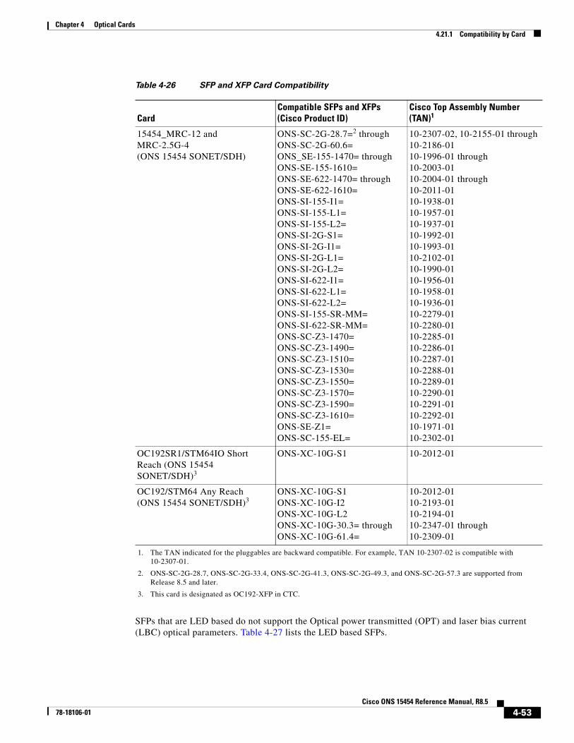
Chapter 4 Optical Cards4.21.1 Compatibility by Card
SFPs that are LED based do not support the Optical power transmitted (OPT) and laser bias current (LBC) optical parameters. Table 4-27 lists the LED based SFPs.
Table 4-26 SFP and XFP Card Compatibility
CardCompatible SFPs and XFPs(Cisco Product ID)
Cisco Top Assembly Number (TAN)1
1. The TAN indicated for the pluggables are backward compatible. For example, TAN 10-2307-02 is compatible with 10-2307-01.
15454_MRC-12 and MRC-2.5G-4(ONS 15454 SONET/SDH)
ONS-SC-2G-28.7=2 throughONS-SC-2G-60.6=ONS_SE-155-1470= throughONS-SE-155-1610=ONS-SE-622-1470= throughONS-SE-622-1610=ONS-SI-155-I1=ONS-SI-155-L1=ONS-SI-155-L2=ONS-SI-2G-S1=ONS-SI-2G-I1=ONS-SI-2G-L1=ONS-SI-2G-L2=ONS-SI-622-I1=ONS-SI-622-L1=ONS-SI-622-L2=ONS-SI-155-SR-MM=ONS-SI-622-SR-MM=ONS-SC-Z3-1470=ONS-SC-Z3-1490=ONS-SC-Z3-1510=ONS-SC-Z3-1530=ONS-SC-Z3-1550=ONS-SC-Z3-1570=ONS-SC-Z3-1590=ONS-SC-Z3-1610=ONS-SE-Z1=ONS-SC-155-EL=
2. ONS-SC-2G-28.7, ONS-SC-2G-33.4, ONS-SC-2G-41.3, ONS-SC-2G-49.3, and ONS-SC-2G-57.3 are supported from Release 8.5 and later.
10-2307-02, 10-2155-01 through10-2186-0110-1996-01 through10-2003-0110-2004-01 through10-2011-0110-1938-0110-1957-0110-1937-0110-1992-0110-1993-0110-2102-0110-1990-0110-1956-0110-1958-0110-1936-0110-2279-0110-2280-0110-2285-0110-2286-0110-2287-0110-2288-0110-2289-0110-2290-0110-2291-0110-2292-0110-1971-0110-2302-01
OC192SR1/STM64IO Short Reach (ONS 15454 SONET/SDH)3
3. This card is designated as OC192-XFP in CTC.
ONS-XC-10G-S1 10-2012-01
OC192/STM64 Any Reach(ONS 15454 SONET/SDH)3
ONS-XC-10G-S1ONS-XC-10G-I2ONS-XC-10G-L2ONS-XC-10G-30.3= through ONS-XC-10G-61.4=
10-2012-0110-2193-0110-2194-0110-2347-01 through 10-2309-01
4-53Cisco ONS 15454 Reference Manual, R8.5
78-18106-01

Chapter 4 Optical Cards4.21.2 SFP Description
4.21.2 SFP DescriptionSFPs are integrated fiber optic transceivers that provide high-speed serial links from a port or slot to the network. Various latching mechanisms can be utilized on the modules. There is no correlation between the type of latch to the model type (such as SX or LX/LH) or technology type (such as Gigabit Ethernet). See the label on the SFP for technology type and model. Three latch types are available: mylar (Figure 4-24), actuator/button (Figure 4-25), and bail clasp (Figure 4-26).
Figure 4-24 Mylar Tab SFP
Figure 4-25 Actuator/Button SFP
Figure 4-26 Bail Clasp SFP
SFP dimensions are:
Table 4-27 LED Based SFPs
SFPs (Cisco Product ID) Cisco Top Assembly Number (TAN)
ONS-SI-155-SR-MM SFP 10-2279-01
ONS-SI-622-SR-MM SFP 10-2280-01
ONS-SE-100-FX 10-2212-01
ONS-SI-100-FX 10-2350-01
6306
5
6306
6
6306
7
4-54Cisco ONS 15454 Reference Manual, R8.5
78-18106-01

Chapter 4 Optical Cards4.21.3 XFP Description
• Height 0.03 in. (8.5 mm)
• Width 0.53 in. (13.4 mm)
• Depth 2.22 in. (56.5 mm)
SFP temperature ranges are:
• COM—Commercial operating temperature range: 23 to 158 degrees Fahrenheit (–5 to 70 degrees Celsius)
• EXT—Extended operating temperature range: 23 to185 degrees Fahrenheit (–5to 85 degrees Celsius)
• IND—Industrial operating temperature range: –40 to 185 degrees Fahrenheit (–40 to 85 degrees Celsius)
4.21.3 XFP DescriptionThe 10-Gbps 1310-nm and 1550-nm XFP transceivers are integrated fiber optic transceivers that provide high-speed serial links at the following signaling rates: 9.95 Gbps, 10.31 Gbps, and 10.51 Gbps. The XFP integrates the receiver and transmit path. The transmit side recovers and retimes the 10-Gbps serial data and passes it to a laser driver. The laser driver biases and modulates a 1310-nm or 1550-nm distributed feedback (DFB) laser, enabling data transmission over single-mode fiber (SMF) through an LC connector. The receive side recovers and retimes the 10-Gbps optical data stream from a positive-intrinsic-negative (PIN) photodetector, transimpedance amplifier and passes it to an output driver.
The XFP module uses the bail clasp latching mechanism, shown unlatched in Figure 4-27 and latched in Figure 4-28. See the label on the XFP for technology type and model.
Figure 4-27 Bail Clasp XFP (Unlatched)
Figure 4-28 Bail Clasp XFP (Latched)
XFP dimensions are:
• Height 0.33 in. (8.5 mm)
1157
2011
5719
4-55Cisco ONS 15454 Reference Manual, R8.5
78-18106-01

Chapter 4 Optical Cards4.21.4 PPM Provisioning
• Width 0.72 in. (18.3 mm)
• Depth 3.1 in. (78 mm)
XFP temperature ranges are:
• COM—Commercial operating temperature range: 23 to 158 degrees Fahrenheit (–5 to 70 degrees Celsius)
• EXT—Extended operating temperature range: 23 to185 degrees Fahrenheit (–5to 85 degrees Celsius)
• IND—Industrial operating temperature range: –40 to 185 degrees Fahrenheit (–40 to 85 degrees Celsius)
4.21.4 PPM ProvisioningSFPs and XFPs are known as pluggable-port modules (PPMs) in CTC. Multirate PPMs for the 15454_MRC-12 card can be provisioned for different line rates in CTC. For more information about provisioning PPMs, refer to the Cisco ONS 15454 Procedure Guide.
4-56Cisco ONS 15454 Reference Manual, R8.5
78-18106-01