Embed Size (px)
Citation preview

PNNL-11407UC-515
Optical-Based Smart Structures forTamper-Indicating Applications
P. SlivaN. C. AnheierK. L. SimmonsH. A. Undem
November 1996
Prepared forthe U.S. Department of Energyunder Contract DE-AC06-76RLO 1830
Pacific Northwest National LaboratoryRichland, Washington 99352

DISCLAIMER
This report was prepared as an account of work sponsored by an agency of the UnitedStates Government Neither die United States Government nor any agency thereof, norany of their employees, make any warranty, express or implied, or assumes any legal liabili-ty or responsibility for the accuracy, completeness, or usefulness of any information, appa-ratus, product, or process disclosed, or represents that its use would not infringe privatelyowned rights. Reference herein to any specific commercial product, process, or service bytrade name, trademark, manufacturer, or otherwise does not necessarily constitute orimply its endorsement, recommendation, or favoring by the United States Government orany agency thereof. The views and opinions of authors expressed herein do not necessar-ily state or reflect those of the United States Government or any agency thereof.

DISCLAIMER
Portions of this document may be illegiblein electronic image products. Images areproduced from the best available originaldocument

Summary
This report is a compilation of several related projects performed from 1991 through 1996concerning the design, construction, and application of optical-based smart structures^) totamper-indicating and sensing secure containers. Due to several influences, the projects were carriedthrough to varying degrees of completion. Cancellation of the overall project at the client levelmotivated the authors to gather all of the technology and ideas about smart structures developedduring these several projects, whether completed or just conceptualized, into one document.Although each section individually discusses a specific project, the overall document is writtenchronologically with each successive section showing how increased smart structure complexity wasintegrated into the container.
The first project presented in this report, which represents the basis of all of the relatedprojects, was initiated by the need of the U.S. Department of Energy (DOE) to find a more costeffective method of securing nuclear materials or related items of high value either in storage ortransport. Although other methods of securing these items existed, all-composite, lightweightcontainers that monitored in real-time did not. The initial demonstration container and the nextcontainer, a secure video system to remotely monitor factory operations, proved that the concept ofoptical fiber-based tamper-indication would wort The tamper-indicating window became of interestbecause it allowed visual inspection of a container's contents or the radioactive contents of a room tobe inventoried without having to enter the room. A second tamper-indicating container for storingand shipping radioactive materials, in this case special nuclear material from dismantled weapons, wasinitiated as a way to reduce visual inspections at DOE storage facilities. This next-generationcontainer had the ability to communicate its status in real-time. It became apparent as the complexityof the smart structure increased, especially with the communication aspect, that tamper-indicatingcontainers had applications beyond storing and transporting nuclear materials. Interest grew withinthe U.S. Department of Defense (DoD) of using smart containers for shipping, storing, andprepositioning high-value material. As a result, the authors received several requests to writeproposals to design and construct smart intermodal-type shipping containers.
This report provides information on the five projects that were initiated involvingoptical-based smart structures. These projects include the first demonstration container, the secondcontainer for secure video applications, smart windows, the next-generation container withcommunications, and the large, intermodal smart shipping containers.
• A prototype secure container was prepared that used continually monitored optical fiber as thesmart structure. A small (-7.6 cm x 10.2 cm x 12.7 cm), matchbox-shaped container, consistingof an inner drawer within an outer shell, was fabricated from polymer resin. The optical fiberwas sandwiched between additional non-optical, strength-promoting fibers and embedded intothe polymer. The additional non-optical fiber provided strength to the container, protected theoptical fiber from damage, hid the fiber, and acted as a decoy. The optical fiber was wound witha winding density such that a high probability of fiber damage would be expected if the
(a) Smart structure, by general definition, is a system comprised of smart materials and othercomponents that is able to respond to external stimuli in an intelligent manner. Fiber optic (orchannel waveguide) is the basis of the smart structure for tamper-indicating containers andwindows because it can sense external stimuli and also carry the resultant signal to themicroprocessor for response.
in

container was penetrated. The inner drawer and outer shell were wound with optical fiber thatoptically coupled when the two halves were joined to form a continuous optical pathway.Electronic circuitry located in the base of the inner drawer sent and received an infrared signalthrough the fiber several times a second (20 Hz). For demonstration, when the drawer wasopened, interrupting the fiber loop and creating a container breach, an alarm beeper wasactivated. The beeper could be turned off using an infrared remote control. When the drawerwas re-closed, the alarm circuitry automatically reset so that any subsequent breach again set offthe beeper.
A tamper-indicating container was prepared to secure a video system that uses activelymonitored optical fiber as the smart structure. Because the video system was already adapted toa steel container, an all-composite, fiber-wound container was not constructed. Additionally,because the steel container had several limiting features, an all-composite, fiber-wound liningcould not be prepared as a single shell and inserted into the steel container. Instead, optical fiberwas wound around six polyurethane foam panels and assembled inside the steel box. Holes inthe container for the video camera lens were made secure by winding spiral disks of opticalfiber, placing them around each hole, and splicing the fiber to the remainder of the woundpanel. Electronic circuitry was designed and prepared that sent and received an infrared signalthrough the optical fiber. The electronics system was designed to activate an alarm beeper if afiber was compromised or an attempt was made to remove the secure container's lid. Theelectronics package performed as designed and although functionally limited, provided thepossible electronic functionalities that can be built into the structure.
A project was initiated to create channel waveguides first on and then within clear polymers fortamper-indicating window applications. Channel waveguides are linear regions of slightlyhigher (than their surroundings) refractive index capable of propagating a light signal much inthe way a fiber optic transmits light. Using procedures closely resembling those for creatingmicroelectronic circuitry, channel waveguides were written in polymers spin-coated on clearpolymer substrates. Varied channel waveguide "circuitry" was written on several substrates todemonstrate the methodology and possibilities. Being able to write circuitry beyond simplelinear patterns opened the possibility of creating sensors on the substrate surface in addition totamper-indication. At project end, a precise method of coupling light into the channelwaveguides was being developed. All that remained was to create the sandwich structure toprotect and hide the channel waveguides.
A tamper-indicating composite container was designed for the transport and storage of specialnuclear material removed from dismantled weapons. In addition to the optical fiber-basedtamper indication designed into previous smart containers, the container had two uniqueembedded sensors. The first was a scintillating fiber embedded in the lid that when placed in aneutron field, reacted with the neutron field to produce light, which was transmitted through thefiber and detected by solid-state photomultiplier tubes. This sensor would detect the removal ofthe lid, removal of the source, or human presence near the container. The second sensoremployed Bragg sensors (gratings) in an embedded optical fiber traversing the lid near each ofthe 12 bolt holes to create a unique (up to) 12-point stress signature once the bolts are tightened.It would be extremely difficult to reproduce the stress signature. Radio Frequency (RF)communication was used to monitor the container's status in real-time.
At the time of these projects, there was a need to advance the state-of-the-art in intermodalshipping containers for military and commercial applications. Because of this need, a nextgeneration tamper-indicating, smart shipping container was designed and conceptualized in
IV
several proposals written to various military agencies. At the time of this report, one of theproposals was selected for funding. This container would sense light, internal moisture(humidity), motion, and temperature (internal and external). The container would be robust forshipping and field environments, lightweight, waterproof, sling capable, and configured forhandling by standard forklifts. Similar to the previous containers designed and constructed bythe authors, the intermodal container would provide physical security for the contents and detect,in real-time, container breaches and general container health (e.g., physical integrity of walls,corners, and doors). The container would include a control system that was self-contained, self-powered, and provided global positioning capability. All of the sensor and global positioninginformation, container health, and inventory movement would be automatically uploaded to anRF tagging system that could be externally interrogated while in transit (e.g., automated cranesystems) and in the field (e.g., field personnel with hand-held readers or satellite uplink).
Smart structure complexity increased with each new container even though the basis fortamper-indication remained essentially unchanged. Optical fiber as the smart material allowed for theaddition of other discrete sensors, fiber optic-based (e.g., secure windows, radiation, stress) orotherwise (e.g., moisture, temperature, motion). All of the containers were designed and constructedso that the optical fiber-based smart structure was an integral part of the container. At the time of thisreport, compared with all other methods of providing tamper-indication for secure containers, thesmart containers designed, developed, and constructed in these projects are the only tamper-indicating containers in which the container itself provides the tamper indication.


Acknowledgments
The authors recognize Kurt Stahl and Ross Gordon who played key roles in the first fewyears of our smart materials projects. The authors also thank Debra Sunberg, Richard Craig, andMary Bliss who, for most of the projects, provided all of the expertise and performed most of theexperiments involving optical fiber transmission. Sergey Kucheryavyy developed many of thechannel waveguide writing techniques for creating secure windows. Hal Undem has been theconsummate program manager; his role in our success cannot be overstated. Except for the securevideo system project, which was funded by Sandia National Laboratory (SNL), and the intermodalshipping container proposals, which were funded internally, all of the projects associated with thisreport were funded by DOE's Office of Non-Proliferation and National Security (NN-20).
vu


Acronyms and Abbreviations
ALARAASTMDERDoDDOEFYGPSICISOLEDOTDRPNNLRFrpmSNLTETA
as low as reasonably achievableAmerican Society for Testing and MaterialsDow Epoxy ResinU.S. Department of DefenseU.S. Department of Energyfiscal yearglobal positioning systemintegrated circuitInternational Standards Organizationlight-emitting diodeoptical time domain reflectometerPacific Northwest National Laboratoryradio frequencyrevolutions per minuteSandia National Laboratorytriethylene tetramine
IX

I
Contents
Summary iii
Acknowledgments vii
Acronyms and Abbreviations ix
1.0 Introduction and Background 1.1
2.0 Tamper-Indicating Demonstration Container 2.1
2.1 Introduction 2.12.2 Experimental Approach 2.1
2.2.1 Optical Fiber 2.32.2.2 Container Design and Fabrication 2.42.2.3 Electronics Package 2.4
2.3 Results and Discussion 2.52.3.1 Optical Fiber 2.52.3.2 Container Fabrication 2.82.3.3 Electronics 2.8
2.4 Applications 2.92.5 Conclusions 2.10
3.0 Optical Fiber-Based Secure Container for Secure Video Applications 3.13.1 Introduction and Objectives 3.1
3.1.1 Introduction 3.1
3.1.2 Objectives 3.2
3.2 Secure Container Fabrication 3.23.3 Phase 1: Secure Container Design, Electronics Package Design,
and Optical Fiber Selection 3.33.3.1 Secure Container Design 3.33.3.2 Electronics Package Design 3.33.3.3 Optical Fiber Selection 3.5
3.4 Phase 2: Filament Winding of a Test Panel andElectronics Package Assembly 3.83.4.1 Filament Winding of a Test Panel 3.83.4.2 Electronics Package Assembly 3.8
XI
3.5 Phase 3: Panel Winding, Final Assembly, and Testing 3.83.5.1 Panel Winding 3.83.5.2 Final Assembly 3.103.5.3 Testing 3.13
3.6 Container Features 3.13
4.0 Smart Tamper-Indicating Windows 4.14.1 Introduction and Objective 4.1
4.1.1 Introduction 4.14.1.2 Objective 4.1
4.2 Scientific Basis and Approach 4.24.3 Experimental 4.24.4 Results and Discussion 4.34.5 Applications 4.64.6 Conclusions and Further Studies 4.6
5.0 Smart Container for Transport and Storage of Neutron-Emitting Sources 5.15.1 Introduction 5.1
5.2 Technical Approach 5.15.3 Experimental 5.35.4 Applications 5.4
6.0 Smart Shipping Containers/Modular Buildings 6.16.1 Introduction 6.16.2 Smart Intermodal Shipping Container 6.1
6.2.1 Introduction 6.1
6.2.2 Objective 6.26.2.3 Demonstrated Technology 6.26.2.4 Approach for Concept Demonstration 6.3
6.2.4.1 Task 1: Sensor Platform Design and Construction 6.36.2.4.2 Task 2: Container Design and Construction 6.4
6.3 Smart Modular Storage Buildings 6.46.3.1 Introduction 6.46.3.2 Concept 6.46.3.3 Applications 6.6
xn

7.0 Conclusions and Lessons Learned 7.1
8.0 References 8.1
Appendix A Schematic Diagrams and Perspective Drawings of Molds Used forFabricating the Optical Fiber-Based Secure Smart Structure Drawerand Outer Shell A.I
Appendix B Block Diagram and Schematic Circuit for Optical Fiber-BasedSmart Secure Container B.I
Appendix C Schematics of Optical Fiber-Based Secure Video ContainerElectronic Circuitry C.I
xm

Figures
2.1. Optical Fiber-Based Smart Secure Container Conceptual Operation 2.2
2.2. Change in Transmittance with Wavelength and Time of Optical Fiber Embeddedin Epoxy During Curing 2.6
2.3. Change in Transmittance with Wavelength and Time of Optical Fiber Coatedwith Silicone Embedded in Epoxy During Curing 2.7
3.1. Change in Relative Transmittance as a Function of Wavelength of Optical FiberAs-Received and After Embedding in Curing Silicone for 23 Hours 3.7
3.2. Test Panel Comprised of 650 m of Corning Incorporated 100/140 CPC3 FiberWound Around Polyurethane Foam 3.9
3.3. Top Panel Showing Band Not Covered By Optical Fiber Resulting fromWinding Around the Holes 3.11
3.4. Top Panel Showing Spiral Disks Securing Each Hole Mountedover the Flat-Wound Fiber 3.11
3.5. Interior of Completed Secure Container Showing Interior Polyurethane LiningBonded over Optical Fiber-Wound Panels 3.12
3.6. Top Panel (Lid) in Place Showing Video Camera Lens Holes 3.12
4.1. Process for Creating Tamper-Indicating Windows Depicting A) Coating on Clear Substrate,B) Forming Waveguide Circuitry, C) Creating the Embedded Circuit, andD) Coupling Light in and out of the Window 4.4
4.2. Microscopic Image of a Rib Waveguide 2x2 Coupler in Polyimideon BK7 Glass Substrate 4.5
4.3. Tamper-Indicating Secure Window in a Door Application 4.7
5.1. Smart Container for Storing and Shipping Neutron-Emitting Materials 5.2
6.1. Conceptual Tamper-Indicating Smart Modular Field Container/Building
or Intermodal Shipping Container 6.5
xiv

Tables
2.1. Characteristics of the Optical Fiber Used in Fabricating the Secure Container 2.3
2.2. Signal Attenuation from Bending Optical Fiber Used in
Fabricating a Prototype Smart Secure Container 2.9
3.1. Optical Fiber Characteristics 3.6
3.2. Percent Signal Attenuation from Bending Five Meters of Corning Optical FiberAround Mandrels of Graduated Radii 3.6
4.1. Laser Parameters for Writing Channel Waveguides inSpin-Coated Photosensitive Film 4.3
xv
1.0 Introduction and Background
This report is a compilation of several related projects performed from 1991 through 1996concerning the design, construction, and application of optical-based smart structures^ totamper-indicating and sensing secure containers. Due to several influences, the projects were carriedthrough to varying degrees of completion. Cancellation of the overall project at the client levelmotivated the authors to gather all of the technology and ideas about smart structures developedduring these several projects, whether completed or just conceptualized, into one document .Although each section individually discusses a specific project, the overall document is writtenchronologically with each successive section showing how increased smart structure complexity wasintegrated into the container.
The first project presented in this report, which represents the basis of all of the relatedprojects, was initiated by the need of the U.S. Department of Energy (DOE) to find a more costeffective method of securing nuclear materials or related items of high value either in storage ortransport. Although other methods of securing these items existed, all-composite, lightweightcontainers that monitored in real-time did not The initial demonstration container and the nextcontainer, a secure video system to remotely monitor factory operations, proved that the concept ofoptical fiber-based tamper-indication would work. The tamper-indicating window became of interestbecause it allowed visual inspection of a container's contents or the radioactive contents of a room tobe inventoried without having to enter the room. A second tamper-indicating container for storingand shipping radioactive materials, in this case special nuclear material from dismantled weapons, wasinitiated as a way to reduce visual inspections at DOE storage facilities. This next-generationcontainer had the ability to communicate its status in real-time. It became apparent as the complexityof the smart structure increased, especially with the communication aspect, that tamper-indicatingcontainers had applications beyond storing and transporting nuclear materials. Interest grew withinthe U.S. Department of Defense (DoD) of using smart containers for shipping, storing, andprepositioning high-value material. As a result, the authors received several requests to writeproposals to design and construct smart intermodal-type shipping containers.
This report provides information on the five projects that were initiated involvingoptical-based smart structures. These projects include the first demonstration container, the secondcontainer for secure video applications, smart windows, the next-generation container withcommunications, and the large, intermodal smart shipping containers.
The first smart structure constructed was a small, matchbox-like container that was asuccessful feasibility demonstration. This container was comprised of densely wound optical fiberembedded in a polymer shell. A laser diode pulsed light through the fiber and a piezoelectric buzzeralarmed if the container shell was compromised or the container was opened.
The second secure, or tamper-indicating, container was constructed to securely house a videocamera system and contained six optical fiber wound panels, each with its own laser diode lightsystem. Interrogating each panel separately permitted isolation of a container breach. Camera lens
(a) Smart structure, by general definition, is a system comprised of smart materials and othercomponents that is able to respond to external stimuli in an intelligent manner. Fiber optic (orchannel waveguide) is the basis of the smart structure for tamper-indicating containers andwindows because it can sense external stimuli and also carry the resultant signal to themicroprocessor for response.
1.1
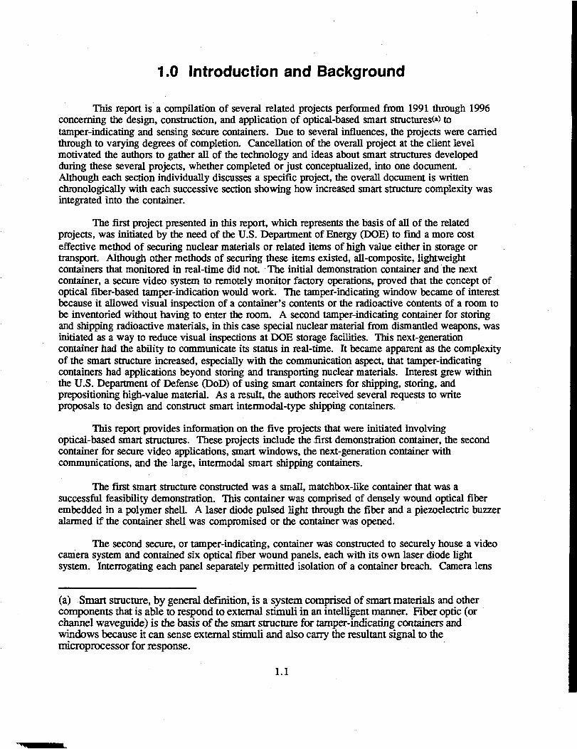
holes were made tamper-indicating by circularly winding optical fiber around each hole and splicingboth fiber ends to the panel fiber to complete the optical circuit. The original video system windowswere comprised of tempered glass with a sensor attached. An attempt to break through the glasswould result in its completely shattering, causing the sensor to trigger an alarm. Searching for abetter way to secure the video camera windows led* to the concept of smart windows.
The goal of the smart windows project was to develop a clear, polymer window with channelwaveguides running through it that would transmit light. It was envisioned that the window could beintegrated into a fiber-wound, tamper-indicating container, wall, or door when see-through capabilitywas needed. A two-step development plan was chosen: 1) to write channel waveguides in a polymercoated on a clear substrate and 2) to write channel waveguides directly into the polymer subsurface.At the end of the two-year project, step one was almost completed.
The third container being developed was for storing and transporting neutron-emittingsources such as special nuclear material from dismantled weapons. It had the typical features of theearlier containers such as composite construction and embedded optical fiber for tamper-indication.In addition, this container was to have radio frequency (RF) communication and a unique compositelid that utilized both embedded fiber optic Bragg sensors for tamper-indication of tightened bolts andembedded scintillating fibers for neutron detection. This project was at the design stage when theoverall program at the client level was canceled.
Similar to the smaller tamper-indicating containers constructed and/or designed, a largeintermodal shipping container was conceptualized and designed. Several proposals to construct atamper-indicating smart intermodal shipping container, including two with unique cooling systems,were marketed to the military. At the time of this report, one of the projects had been selected forfunding and the authors were waiting on the funding disposition.
1.2

2.0 Tamper-Indicating Demonstration Container
2.1 Introduction
The objective of this study was to demonstrate optical fiber/polymer matrix smart structureproperties through fabrication of a small, secure container; identify potential problems associatedwith design and fabrication; and ascertain application and growth potential of optical fiber/polymermatrix smart structures into additional areas.
Smart materials and structures are part of a rapidly evolving, multidisciplinary approach tousing a material's intrinsic properties or combining materials to achieve inherent intelligence(Rogers 1989; Ahmad et al. 1990). Smart materials may be defined as materials that possess intrinsicproperties capable of responding and adapting to external stimuli. The material's intelligence maybe the result of its composition, processing, microstructure, presence of defects, or conditioning.Smart structures may be comprised of integrated smart materials and/or more discrete componentssuch as actuators or sensors which, in combination, provide the required intelligence.
Optical fibers have been the basis of advanced polymer composites to prepare intelligentstructures (Claus 1991). Optical fibers are small, are immune to electromagnetic interference, arelightweight, can be embedded in other materials, have an adjustable composition, and can operate inharsh environmental conditions. Optical fiber-based smart structures have the ability, via embeddedor attached optical fiber (the smart material) and the associated electronic circuitry, to monitor thepolymer's physical integrity and structural behavior during use. The unique ability of optical fiberto act as a signal transmitter as well as to modulate a propagating optical signal as a response toexternal stimuli has led to numerous applications of optical fiber-based smart structures. Althoughcapable of detecting electrical and chemical phenomena, optical fiber sensors have been developedprimarily for determining strain, thermal expansion, and vibration of structural components.
Non-optical glass or polymer fibers are typically embedded into polymer structures toenhance strength and toughness. Replacing a portion of the structural fiber with optically conductingfiber permits fabricating robust, optically-active structures such as secure containers. Securecontainers are optical fiber-based smart structures that offer the ability to continually or passivelymonitor the integrity of the container walls (shown conceptually in Figure 2.1). Continuallymonitored, secure containers monitor in real-time, with container breaching activating the smartstructure. Smart structure activation can lead to numerous consequences within the containerdepending on the specific application of the container, the size of the container, and the complexityof the accompanying electronics. At a minimum, smart structures can be given the ability torecognize and record container breaching. Difficulty in defeating the secure container depends onthe smart material's stealth and the smart structure's complexity, which can be provided by the smartmaterial being incorporated into the container walls with additional, non-active decoy material.
2.2 Experimental Approach
The secure container chosen for demonstration was comprised of three parts: optical fiber,fiber reinforced polymer matrix, and an electronics package. The project was completed in threephases. The first project phase was to design the container and electronics and determine a suitable
2.1

SECURE CONTAINER
STORING HIGH
VALUE MATERIAL
REMOTE CONTROL
WINDOW (HIDDEN)
INTRUSION
DEVICE
EMBEDDED OPTICAL
FIBERS DISTURBED
OR BROKEN
ALARM
TIME
OPTICAL FIBER
SIGNAL
Figure 2.1. Optical Fiber-Based Smart Secure Container Conceptual Operation

optical fiber for embedding into the polymer matrix. The second phase was to fabricate thecontainer without optical fiber to evaluate the fabrication process, assemble the electronics package,and evaluate optical fiber performance in the candidate epoxies. The final project phase involvedfabricating the container with optical fiber, connecting the electronic circuitry, and testing.
2.2.1 Optical Fiber
Characteristics of the optical fiber were chosen for the secure container application. The fiberwas to have a glass core and cladding (buffer optional), be multimode, have an overall diameter assmall as possible, have minimal loss of optical signal upon bending, be able to transmit (in the nearinfrared) up to a kilometer with minimal loss of optical signal, be compatible with the polymermatrix, and be relatively inexpensive. Commercial-grade optical fiber was obtained from PolymicroTechnologies Inc., the characteristics of which are listed in Table 2.1. The fiber obtained had a silica-based core and cladding and a protective polyimide buffer.
A series of tests were performed in order to determine the effect of embedding the opticalfiber in a polymer. A known length of fiber, typically a few meters, was coiled and placed into thebottom half of a 500-ml polyethylene bottle. The fiber ends were cleaved and attached to aspectrophotometer (U.O.P. Guided Wave, Inc. Model 100 Spectrophotometer) that transmittedlight pulses over a wavelength range of 350 to 1000 nm. The spectrophotometer measurestransmittance as a function of time and wavelength. An ultraviolet/near infrared transmissive fiberwas used as the standard reference cable. A transmittance measurement was taken on the coiled fiber(representing time zero) and then the polymer poured over the fiber to embed it. Transmittancemeasurements were taken on the fiber at approximately 10-15 minute intervals until the polymercured.
Three different epoxies were prepared for fiber embedding: 1) Dow (Dow ChemicalCompany) Epoxy Resin (DER) 332 epoxy resin with 10 parts per hundred triethylene tetramine(TETA) (Kodak Chemical Company); 2) DER 332 epoxy resin with 40 parts per hundred Jeffamine(Texaco Chemical Company) T-403 hardener, and 3) DER 332 epoxy resin with 80 parts perhundred Versamide (General Mills Chemical Company) 140 hardener. The first two hardenersproduced rigid epoxy after curing, the Jeffamine taking longer to cure than the TETA. Longer
Table 2.1. Characteristics of the Optical Fiber Used in Fabricating the Secure Container*
• Composition: Pure Silica/Doped Silica (Core/Cladding)• Buffer Composition: Polyimide• Core/Cladding/Buffer Outer Diameters: 100 um/110 nm/125 um• Transmission Range: 380-2500 nm• Operating Temperature: To 400°C• Ultra-low OH- Core• Step Indexed• Radiation Resistant• High Laser Damage Threshold
* Obtained from Polymicro Technologies Inc.: Fiber FHZ100110125.
2.3

curing times are associated with less shrinkage; therefore, it was expected that the Jeffamine-containing epoxy would result in lower shrinkage. The Versamide is a polyamide hardener thatkeeps the epoxy semi-flexible after curing.
Because the optical fiber would make numerous bends when wound into the container, aseries of tests were performed on the optical fiber to determine the loss in transmission when the fiberwas bent. One end of a known length of optical fiber was attached to an optical time domainreflectometer (OTDR). The remaining fiber was bent over a series of mandrels with radii of 3.5, 1.3,1.0, and 0.6 cm at wavelengths of 650 and 850 nm and the signal attenuation measured. Thecontainer was operated at 850 nm, and 650 nm was used as a check.
2.2.2 Container Design and Fabrication
The container consisted of a five-sided drawer that slid into a five-sided outer shell. Both theshell and drawer were plastic composites consisting of glass reinforcing fiber (carbon or Kevlar fibercould also be used) in a polymer resin matrix. The two container parts used a combination ofreinforcing mat and filament wound, unidirectional fiber. Optical fibers were filament-wound withinthe reinforcing layer with a spacing close enough that attempts to breach the container wall damagedthem.
Mold designs for the drawer are shown in Appendix A (Figures A.I and A.2). Acombination of reinforcing mat, reinforcing fiber, and optical fiber were wetted with polymer andwrapped on the mold mandrel shown in Figure A.I to a thickness of approximately 0.25 cm. Theends of the optical fiber were inserted into Teflon tubing to keep them clean for later attachment ofconnectors. The polymer was allowed to cure and then the bottom plate of the mold removed.Reinforcing mat was applied to the bottom of the drawer and around the cured material (still on themold). The assembly was inserted into the mold cavity (shown in Figure A.2) to provide a fixedoutside shape for the part. After the polymer was cured, the part was carefully removed from themold. Similar steps were followed to produce the shell. The mold for the shell is shown in FigureA.3.
2.2.3 Electronics Package
The secure container's electronics package was designed to provide a basic example of thefunctionality that could be built into such containers. Depending on the container application,circuitry could be designed and miniaturized, for example, to reduce power consumption, providetelemetry, and initiate a range of responses. Therefore, the secure container circuitry demonstrated inthis study should be viewed as a starting point, instead of an end point. The electronic circuitrydesigned was capable of being embedded; however, it was decided to place the circuitry in the bottomof the drawer for viewing and easy access for changes. The circuitry implemented an opticaTpitch-catch" scheme. A block diagram and schematic are shown in Appendix B, Figures B.I and B.2. Aninfrared light-emitting diode (LED) launched (pitches) pulses of light into the embedded opticalfiber. The pulses were approximately 500 microseconds wide and were launched at a rate ofapproximately 20 Hz. When the optical fiber path was uninterrupted (drawer was closed andembedded fiber winding was unbroken or undisturbed), the pulses arrived at the receiving (catch) endand were detected by a photodiode. The signal was amplified and shaped, and fed to a missing pulsedetection circuit. The missing pulse circuit produced a logic 0 signal as long as the prescribed pulseswere detected as expected. However, if one or more of the pulses did not arrive, due to fiber
2.4

breakage or an open drawer, a logic 1 was output by the missing pulse detector. In the presentcircuit, the logic 1 level caused a piezoelectric buzzer (mounted to the circuit board) to sound. Sincethe pulses were expected at a 20 Hz rate (period of 50 milliseconds), any breach lasting longer than50 milliseconds would be detected. The circuitry also included a remote controldetector/demodulator, remote control logic, and a "valid transmission" indicator LED. Four AAAbatteries powered the circuit and provided sufficient capacity for approximately 168 hours (7 days)of operation.
Infrared remote control of the circuit was implemented in order to demonstrate its feasibility.The remote control gave the capability to turn off the piezoelectric buzzer during a breach. Theinfrared LED in the hand-held controller emitted a burst of light pulses which constituted a uniqueidentification address. The encoded light pulses were detected by a phototransistor, with appropriateoptical filter, that was mounted on the inside face of the drawer. The pulse stream was amplified,shaped, and decoded. If the decoded identification address matched the expected address, thetransmission was considered valid and a signal was sent to a logic circuit that turned off the buzzer.Subsequent transmissions from the remote controller toggled the buzzer on and off as long as thebreach condition remained. When the optical fiber path was re-established, as when the containerdrawer is closed, the circuit automatically returned to its default mode, wherein any subsequentbreach would cause the alarm to sound. If the transmission was received when there was no opticalfiber breach, the transmission was ignored. This arrangement ensured that the circuit would alwayssound the alarm when the fiber loop was broken, eliminating the possible situation where the alarmdid not sound when the container was opened due to its being remotely turned off during a previousdemonstration.
2.3 Results and Discussion
2.3.1 Optical Fiber
All of the epoxies chosen caused significant loss in signal transmittance through the opticalfiber during curing over the wavelength spectrum tested. There was little difference in responsesobserved between epoxies. The change in transmittance as a function of wavelength and time foroptical fiber embedded into TETA-hardened epoxy is shown in Figure 2.2. The change intransmittance shown is typical of all the epoxies, including the longer-curing Jeffamine. The firstscan taken is represented by the top of the thick upper curve at a relative transmittance of 16-17.Each successive scan decreased in relative transmittance. The bottom of the lower curve representsthe last scan taken - seven hours from when the epoxy was initially poured over the optical fiber. Therelative transmittance decreased to ~12, representing a signal attenuation of 25%-30% over the metertested (850 nm was used as the reference).
During curing, epoxies shrink, which ultimately translates to compressive stresses beingexerted on the optical fiber. The non-compliant polyimide buffer only serves to translate the load tothe optical fiber. The resultant high optical signal losses from fiber strain were unacceptable becauseeven the small container being fabricated may contain up to 100 m of optical fiber. In order toreduce or eliminate straining the optical fiber, a 25 um layer of silicone (General Electric Silicones,GE RTV 615) was coated onto the optical fiber. Silicone is a very compliant polymer compatiblewith most epoxies and allows the optical fiber to essentially "float" in the silicone coating. Figure2.3 shows the change in transmittance as a function of wavelength and time for silicone-coatedoptical fiber embedded in Jeffamine-hardened epoxy. The relative transmittance curve shown
2.5

O\
LN
CE
i«5
1-RA
NSK
LU>
RE
LA7
36.00
30.00
24.00
18.00
12.00
6.00
0.00 I T I I I I I I I I I350 404 458 513 567 621 675 729 783 838 892 946 1000
WAVELENGTH (NM)
Figure 2.2. Change in Transmittance with Wavelength and Time of Optical Fiber (PolymicroTechnologies FHlOOl 10125) Embedded in Epoxy (DER 332/TETA) During Curing.Sixty scans were made over seven hours.
LU
NS
MH
fET
RA
V-
UJ
36.00
30.00
24.00
18.00
12.00
6.00
0.00 I I I I I I I I I I I 1350 404 458 513 567 621 675 729 783 838 892 946 1000
WAVELENGTH (NM)
Figure 2.3. Change in Transmittance with Wavelength and Time of Optical Fiber (PolymicroTechnologies FHZlOOl 10125) Coated with Silicone Embedded in Epoxy (DER332/Jeffamine Hardener) During Curing. A minimum of 42 scans were made.

represents 42 hours of scanning, with the very bottom of the curve representing the last scan. Theoverall relative transmittance loss at 850 nm was essentially zero. Because the epoxy hardened withJeffamine resulted in similar signal attenuation in the uncoated optical fiber, it was assumed that thereduced signal attenuation was due to the silicone coating absorbing the stresses caused by epoxyshrinkage. Additional work would need to be done to further reduce transmittance losses if largersecure containers are to be realized.
Results of the bend tests are given in Table 2.2. As expected, the signal attenuation increasedas the fiber was bent to a smaller radius. A bend radius of 3.5 cm was considered too large to bepractical for the present container size. The signal attenuation at a bend radius of 1.3 cm isacceptable for the container size and the transmission capabilities of the fiber. Larger containers withmore bends may require varying the fiber and increasing the bend radius to minimize signalattenuation.
2.3.2 Container Fabrication
Three problems were encountered during fabrication of the prototype secure container. Themajor problem was removing the filament-wound outer shell from the mold. The shell must be ableto slide easily from the mold to minimize damage. To facilitate removal, the outer shell mold wasremachined with a 3° taper, the mold split, and a wedge inserted to assist in removal of the part.Diagrams of the modified outer shell mold with the inserted wedge are given in Figures A.4 throughA.7 (Appendix A). No further difficulties in part removal were experienced.
Several centimeters of free fiber must be available at the two fiber terminals of both the outershell and drawer after fabrication to provide adequate length for attaching connectors. It is difficultto keep the fiber ends completely resin free while the parts are wound. This problem was resolved bywinding plastic film over one end of the fiber and threading the other fiber end under the film afterthe winding was completed. Resin was then painted over the fiber to avoid contact with the protectedends.
The original molds were designed to create channels on both sides of the drawer to containthe optical fiber connectors so that they would uncouple when the drawer was removed (see FigureA. 3). Difficulty in attaching (embedding) the fiber connectors in the two channels and the limitedworkscope led to the decision to not have the connectors uncouple for the first prototype container(see redesigned mold in Figure A.4). Consequently, for demonstration purposes, audible signalactivation (i.e., simulated penetration) required the manual separation of optical fiber connectors.The logistics of attaching the fiber connectors were to be resolved during the next program phase.
2.3.3 Electronics
In order to simplify the drawer design, no optical window for the infrared on/off remotecontrol was provided. The remote control optical pulses must pass through the drawer front wall,which was comprised of embedded optical and strength fibers, before reaching the phototransistor.Although operable, the associated optical absorption and scatter limited the remote control range toseveral centimeters. Increasing the distance of remote control operation was to be undertaken in thenext program phase.
2.8

Table 2.2. Signal Attenuation (in decibels/bend) from Bending Optical Fiber Used in Fabricating aPrototype Smart Secure Container*
Mandrel Radius (cm)
3.51.30.950.63
Wavelength650
NL#0.02 db/bend0.040.08
(nm)
0.04
850
NLdb/bend
0.06
* Polymicro Technologies, Inc. Fiber FHZ100110125.* NL = no apparent loss.
The container used four AAA batteries capable of powering the electronics for approximately168 hours (7 days) of operation. Battery life is the limiting factor for any portable smart structure.A "sleep mode" could be introduced that shuts off the batteries during periods of inactivity. Theelectronics could then be reactivated by one of several methods, for example, container movement,surface interaction, or remote control.
2.4 Applications
The work was performed to demonstrate the capabilities of optical fiber smart structuretechnology and to serve as a basis from which to expand smart structure capabilities. Electronicallyactive secure containers such as the one fabricated in this study could be expanded to almost any sizewith careful selection of optical fiber, container design, and compatible electronics. Large containersfor shipping, field use, or storing stationary objects could also be prepared with a passive system(without active electronics), with container integrity being checked periodically with an OTDR.Polymer matrix adaptability permits the fabrication of complex-shaped containers and allowsadditional smart structures to be embedded. Having all of the container's components embeddedincreases container ruggedness and security.
Smart structure electronics could be adapted and expanded to perform almost any function.For the container prepared in this study, tampering with the optical fiber triggered a buzzer.Capacitors, telemetry, destructive devices, or sensors could also be activated by the triggeringmechanism. Electronics could be expanded to include real-time recording of container intrusion,remote activation, and communication with other smart structures.
The concept of smart materials fabricated from optical fibers has application beyond securecontainers. Wall panels could be prepared in a manner similar to a secure container wall, only on alarger scale. Panels could be prepared that join and interlock so that the resultant wall becomes asingle unit. Temporary secure buildings and limited access areas could be created in this manner.
The concept of polymer-embedded optical fiber-based smart materials developed in thisstudy is also adaptable to sensors. Chemical sensors could be prepared by embedding an opticalfiber array into a polymer sheet that is then coated with another polymer sensitive to the specificchemical. As die sensitive coating comes in contact with die chemical, it swells which places pressure
2.9

on the optical array. Changes in the optical fiber refractive index could be detected through lightattenuation. Special pressure sensors could also be designed using the same concept, with thepressure being exerted directly on the embedded optical fiber. The chemical or pressure sensorscould be single, stand-alone units, or be part of a secure container wall.
2.5 Conclusions
The prototype secure container prepared in this work is an example of an optical fiber-basedsmart structure. Several fabrication problems were resolved. The electronics package performed asdesigned and although functionally basic, revealed the possible electronic functionalities that couldbe built into optical fiber smart structures. The primary limitation to electronically active portablestructures continues to be battery life.
The knowledge gained from fabricating the secure container could be applied to other securecontainers, smart wall structures, and pressure-based sensors. Through judicious selection ofmaterials and fabrication methods, a host of optical fiber-based smart structures could be prepared.
2.10

3.0 Optical Fiber-Based Secure Container forSecure Video Applications
3.1 Introduction and Objectives
3.1.1 Introduction
Optical fibers have been the basis of advanced polymer composites used to prepare intelligentstructures. Optical fibers are small, immune to electromagnetic interference, are lightweight, can beembedded in other materials, have an adjustable composition, and can operate in harsh environmentalconditions. Optical fiber-based smart structures have the ability, via embedded or attached opticalfiber (the smart material) and the associated electronic circuitry, to monitor the polymer's physicalintegrity and structural behavior during use. The unique ability of optical fiber to act as a signaltransmitter as well as to modulate a propagating optical signal as a response to external stimuli has ledto numerous applications of optical fiber-based smart structures. Although capable of detectingelectrical and chemical phenomena, optical fiber sensors have been developed primarily fordetermining strain, thermal expansion, and vibration of structural components.
Non-optical glass or polymer fibers are typically embedded into polymer structures toenhance strength and toughness. Replacing a portion of the structural fiber with optically conductingfiber permits fabricating robust, optically-active structures such as secure containers. Securecontainers are optical fiber-based smart structures that offer the ability to continually, intermittently,or passively monitor the integrity of the container walls. Continually monitored secure containersmonitor in real-time, with container breaching activating the smart structure. Smart structureactivation can lead to numerous consequences within the container, depending on the specificcontainer application, container size, and the complexity of the accompanying electronics. At aminimum, smart structures can be given the ability to recognize and record container breaching.Difficulty in defeating the secure container depends on the smart material's stealth and the smartstructure's complexity, which can be provided by the smart material being incorporated into thecontainer walls.
Sandia National Laboratory (SNL) was preparing a field-worthy stationary surveillance videosystem that was housed in a rectangular, six-sided, metal box with a hinged lid. It was imperative thatthe metal box be secure even with camera lens viewing ports, vent holes, and power/connectioncabling ports machined into it. It was also important that the video system be easily accessible whennecessary. It was not necessary that the box security system be impenetrable, only that it be tamper-proof.
Pacific Northwest National Laboratory (PNNL) has prepared secure containers by filamentwinding optical fiber around a preform and then embedding the fiber in a polymer matrix via resintransfer molding. In this manner, a secure container was prepared that uses continually monitoredoptical fiber as the smart structure. A small matchbox-shaped container consisting of an inner drawerwithin an outer shell was fabricated from polymer resin. The optical fiber was sandwiched betweenadditional non-optical, strength-promoting fibers and embedded into the polymer. The additionalnon-optical fiber provided strength to the container, protected the optical fiber from damage, hid thefiber, and acted as a decoy. The optical fiber was wound with a winding density such that a highprobability of fiber damage would be expected if the container was penetrated. The inner drawer andouter shell were wound with optical fiber that optically couples when the two halves are put together
3.1

to form a continuous optical pathway. Electronic circuitry located in the base of the inner drawersent and received an infrared signal through the fiber several times a second. For demonstration,when the drawer was opened, interrupting the fiber loop and creating a container breach, an alarmbeeper was activated. The beeper could be turned off via an infrared remote control. When thedrawer was re-closed, the alarm circuitry automatically reset so that a subsequent breach again set offthe alarm.
PNNL was contracted by SNL to design and fabricate a similar optical fiber-based securecontainer that would be compatible with both the video camera system and its metal box. Workbegan in August 1993 under a time constraint to finish the container as soon as possible. This timeconstraint, and especially the limitations introduced by the metal box design, influenced manydecisions during design and fabrication. Differences in the actual secure system fabricated comparedwith the design that would have been implemented without the metal box limitations are notedthroughout the report.
3.1.2 Objectives
The objectives of the study were to fabricate a secure container compatible with the SNLvideo system and the metal box, including securing the perimeter of round openings and the lid;identify potential problems associated with secure container design and fabrication; and ascertainadvantages and disadvantages of the secure container and its potential.
3.2 Secure Container Fabrication
A Hoffman metal box was received from SNL in August 1993. A 2.5-cm diameter hole wasmachined into the front for power cabling by PNNL. The two 5.1-cm holes for the video cameralenses were to be machined into the metal box lid by SNL at a later date. A separate grouping of 15small air vent holes, 1 mm in diameter, was machined into one side of the box by PNNL per SNL'srequest. The convention used throughout the report to label top, sides, etc. is as follows. If the metalbox was positioned with the lid opening up and away from you (the hinge horizontal), the bottomwas against the floor, the back was the side under the hinge, the front was opposite the back, the twosides were the other two vertical sides of the box, and the lid was the top.
The secure container consisted of two parts: 1) a series of panels comprised of optical fiberwound around polyurethane foam and 2) an electronics package. The project was completed in threephases. The first project phase was to design the container and electronics and determine a suitableoptical fiber for filament winding. The second phase was to wind a test panel to evaluate the windingprocess (especially related to optical signal transmission), and assemble the electronics package. Thefinal project phase involved winding the panels, final assembly, and testing. Container fabrication ispresented in order of the phases presented above.
3.2
3.3 Phase 1: Secure Container Design, Electronics PackageDesign, and Optical Fiber Selection
3.3.1 Secure Container Design
Designing and fabricating the secure container as a new concept without constraints wouldinvolve filament winding optical and strength-enhancing fibers into a rectangular, five-sided preformfollowed by resin transfer molding to embed the fiber. This composite box plus a similarlyfabricated lid, both molded to size, would replace the metal box, which was considered an integralpart of the video system housing package. If the constraint of fabricating a secure container involvedbeginning with a simple metal box with a hinged lid, a secure container exactly like the one indicatedabove could be fabricated and inserted into the metal box and under the lid as a "secure liner."However, the secure liner method could not be used for the secure video application due to a featureof the metal box. The opening under the lid had a lip around the perimeter that overhung the boxinterior. This feature precluded creating a second, optical fiber-wound container that could beslipped into the metal box as a lining. Consequently, the secure lining for the metal box had to befabricated in six parts (i.e., panels) so that each panel could be positioned properly on the bottom orunder the lip to assure security. The secure container lid panel was designed to be optically coupledvia two pin connectors to. side-wall panels so that jarring or opening the lid would trigger the alarm.
The secure holes required for the video system presented a special design and fabricationproblem for the secure container. Simple filament winding in only one direction, like that chosen forthe panels, did not allow any of the panel area adjacent to the hole to be covered by fiber unlesswinding was performed in multiple directions (envision infinite straight lines tangent to a circle).Optical fiber windings in different directions to secure the hole would result in an unacceptable build-up of fiber near the edge of the hole from overlap and require at least a 50% increase in fiber length.Consequently, alternative methods of winding the holes were pursued. The accepted design andmethod was to wind a separate fiber into a spiral to create a fiber "disk" tens of centimeters indiameter. The inner diameter of the fiber spiral equaled the hole's diameter. Extra fiber was left ateither end of the spiral for direct splicing to the remaining wound fiber on the panel.
3.3.2 Electronics Package Design
Preparing the secure container in separate parts provided an opportunity to create anelectronics package that allowed each panel to be monitored individually if desired (a compositecontainer may have used only two fiber loops- the box and the lid). Consequently, seven circuitswere prepared, one for each panel and a spare. Although the video system will in practice have accessto external electrical power, the secure container circuitry was designed with battery power fordemonstration purposes. A detailed circuit description follows.
The circuit was powered by four C batteries connected in series to provide a total of 6 volts.An on/off switch was inserted immediately following the battery so that when the switch is off, nocurrent flows. A 1N4003 diode placed in series with the switch provided protection against incorrectbattery polarity and also dropped the battery voltage by approximately 0.7 volts. The resulting 5.3volt level was used for Vss (the supply voltage) throughout the rest of the circuit. Integrated circuit(IC)9 is a low-power DC-DC converter which was configured to output -12 volts. The -12 volt outputvoltage appeared on pin 5 of IC9 and was used as Vee (laser diode voltage supply) for the laser diodedrivers, IC1-IC7.
3.3

ICIO is a CMOS dual-timer chip which was used to generate pulses with 9 millisecondsduration and 10% duty cycle. The 5 volt amplitude pulses appeared at pin 9 of ICIO. IC8 and IC11weTe non-inverting buffer/driver chips which provided an interface between the CMOS 556 (ICIO)and the TTL-based IR3C01 laser diode drivers (IC1-IC7). After being buffered by IC8 and IC11, thepulses were connected to pin 5 of IC1-IC7. These seven IC's were laser diode drivers, which drovethe Seastar #CL-100-10 laser diode modules (the actual laser diode housed in the CL-100-10 was aSharp LT015MD). The laser diodes, TX1 through TX7, had a built-in photodiode which could beused to monitor and stabilize the output power of the laser diode, providing stability over a widerange of ambient temperatures. The IR3C01 made use of the built-in photodiode for this purpose,and also provided a "soft start" function which protected the fragile laser from being destroyed dueto current overload caused by power supply spikes, etc. The output power level of each laser diodewas set by its associated 100K potentiometer. When the signal on pin 5 of IC1-IC7 was TTL high, thelaser was turned on and operated at the pre-set power level. When pin 5 went low, the laser was turnedoff.
After traversing the optical fiber, the optical pulse arrived at the Seastar CP-100-10photodiode receiver, RX1-RX7. The receiver module contained a Fujitsu FIDO8T13TX siliconphotodiode. The signal current from the photodiode was applied to pin 6 of the combination op-amp/comparator LM392, IC12-IC18. Pin 6 was the inverting input of the op-amp. The op-amp wasconnected in a transimpedance configuration which converted the photocurrent into a voltage via thefeedback resistor between pins 6 and 7 of the IC. The signal at pin 7 was a 9 milliseconds, positivevoltage pulse with an amplitude corresponding to the intensity of the laser light arriving at thephotodiode. This voltage pulse was applied to the inverting input (pin 2) of the comparator portionof IC12-IC18. The 200KQ and 100KQ resistors form a reference voltage of 0.002*Vss againstwhich the voltage pulse was compared. The comparator was an open-collector output device, whichwas pulled up to Vss by a 330Kfl resistor. If the voltage pulse was greater than 0.002* Vss(approximately 10 mV with fresh batteries), the comparator output went to zero volts. When thevoltage pulse was less than the reference voltage, the comparator output went to 5 volts. Therefore,the signal at pin 1 of IC12-IC18 was an inverted version of the original modulation signal from IC10.Note that DIP switches S1-S7 were used to disable the output of IC12-18, respectively, by groundingthe output stage of the comparator thereby keeping the signal at zero volts regardless of the opticalsignal present at the corresponding photodiode.
IC19 was a 4075 CMOS triple three-input OR gate. The outputs of the comparators wereapplied to the inputs of the OR gates in such a way as to give a low logic level at pin 10 only when allseven of the comparator outputs were simultaneously low; if any or all of the comparator outputswere high, pin 10 would go high. Due to the signal inversion at the comparator, in the absence oflight the comparator signal was a high logic level. Therefore, if one or more of the fiber optic loopswas broken, pin 10 of IC19 would always remain high, even when the signal from the unbroken loopswent low as their optical pulse was detected. If no fiber loops were broken, or if all broken or inactiveloops were disabled using S1-S7, pin 10 of IC19 output a pulse train which was at a high logic levelfor 81 milliseconds and a low level for 9 milliseconds, which was an inverted version of the originalmodulation signal from IC10. Pin 10 of IC19 was connected to a "missing pulse detector" circuitimplemented by Ql and IC22. The output of the missing pulse detector appeared at pin 3 of IC22.This signal would remain at a high logic level only as long as pulses arrived continually from pin 10of IC19. Thus, if one or more of the fiber optic loops was broken, the missing pulse detector saw asteady high logic level as opposed to a pulse train, and the logic level at pin 3 of IC22 went low.
The output logic level from pin 3 of IC22 was fed to a logic section consisting of IC20 andIC21. IC20 was a 4011 quad 2-input NAND gate and IC21 was a 4013 dual D flip-flop. Thefunction of these two IC's was to implement a reset capability which silenced the piezoelectric buzzer
3.4

when a fiber loop was open, as is often desirable when demonstrating the function of the securecontainer. As long as the reset switch (a momentary normally open switch) was left open, this logicsection inverted the output of the missing pulse detector, with a low logic level appearing at pin 4 ofIC20 when the container was not breached, and a high logic level when one or more fiber loops wasopen. Pin 4 of IC20 was connected to a piezoelectric buzzer excitation circuit consisting of thebuzzer and Q2. A high logic level on pin 4 of IC20 caused the excitation circuit to oscillate,sounding the buzzer. When one or more fiber optic loops was open and the buzzer was sounding, amomentary closure of the reset switch applied a high logic level to the clock input of the flip-flop(IC21), which caused the output of IC20 (pin 4) to change level, thereby silencing the buzzer.Subsequent closings of the reset switch effectively toggled the output (pin 4) of IC20, which in turntoggled the buzzer on and off. The reset switch was ignored if it was pressed when none of the fiberoptic loops was open. In addition, if the buzzer had been silenced by the reset circuit, the buzzer wasautomatically "re-armed" when the optical signal was re-established so that subsequent containerbreaches would always sound the alarm, regardless of the reset state the circuit was previously left in.
3.3.3 Optical Fiber Selection
Optical fiber characteristics were chosen based on the secure container application. Eachpanel would require from 500 to 900 m of fiber of which 50 to 100 m would be in bending mode;therefore, signal attenuation had to be minimal. The fiber was to have a large glass core andcladding, be multimode, have an overall diameter including buffer of 250 \im or less to meet theclient's secure spacing requirement, have low bending loss characteristics, be operational in the near-IR to minimize attenuation, be compatible with the silicone polymer used for coating the fibers, andbe relatively inexpensive. Commercial-grade optical fiber was obtained from Corning Incorporatedthat met the requirements, the characteristics of which are listed in Table 3.1.
After filament winding around the polyurethane panels, the fiber was painted with silicone(Dow Corning Silastic 932 RTV [Dow Chemical Company]) to bond it to me panel and for generaldamage protection. A test was performed in order to determine the effect of having the optical fiberin contact with the curing silicone. Often solvents in polymer resins will attack fiber buffer coatingsand polymer resin shrinkage (or expansion) can induce strains in the fiber causing signal losses. Thelatter phenomena was observed in previous secure containers fabricated using epoxies at PNNL.
For the test, a known length of fiber, typically a few meters, was coiled and placed into thebottom half of a 500-ml polyethylene bottle. The fiber ends were cleaved and attached to aspectrophotometer (U.O.P. Guided Wave, Inc. Model 100 Spectrophotometer) that transmittedlight pulses over a wavelength range of 350 to 1000 ran. The spectrophotometer measurestransmittance as a function of time and wavelength. An ultraviolet/near infrared transmissive fiberwas used as the standard reference cable. A transmittance measurement was taken on the coiled fiber(representing time zero) and then the silicone poured over the fiber to embed it. Transmittancemeasurements were taken on the fiber at approximately 10-15 minute intervals until the siliconecured.
The change in transmittance as a function of wavelength and time for the Corning opticalfiber as-received and after embedding into Dow Coming silicone is shown in Figure 3.1. The as-received scan is represented by the upper curve and the lower curve represents the last scan takenapproximately 23 hours from when the silicone was initially poured over the optical fiber. Thechange in relative transmittance observed at 850 nm (~4%) is within experimental error (3%-5%),indicating negligible signal attenuation over the 5 m of fiber tested. Negligible transmission loss was
3.5

Table 3.1. Optical Fiber Characteristics*
Composition: Silica/Silica (Core/Cladding)• Graded Index• Buffer Composition: Acrylate• Core/Cladding/Buffer Outer Diameters: 100 um/140 nm/250 pm• Operating Temperature: -60"C to 85°C• Effective Index of Refraction: 1.51 @ 850 nm• Attenuation at 850 nm: 3.6 db/km• Cost: $0.33/m
• Obtained from Corning Incorporated: Fiber 100/140 CPC3.
expected because silicone is a very compliant polymer unlikely to induce strains in the fiber and theacrylate buffer was expected to be quite resistant to chemical attack from the acetic acid used as thesolvent.
Because the optical fiber will make numerous bends when wound into the container, a seriesof tests were performed on the optical fiber to determine the loss in transmission when the fiber isbent. One end of a five meter length of optical fiber was attached to an OTDR. The remaining fiberwas wound over a series of mandrels with radii of 0.64,1.0, 1.2, and 1.4 cm and the signal attenuationmeasured at a wavelength 850 nm. A new length of fiber was cut for each test.
Results of the bend tests are given in Table 3.2. As expected, the signal attenuation increasedas the fiber was bent to a smaller radius. The signal attenuation did not reach an acceptable valueuntil a bend radius of 1.4 cm. It should be noted that in the process of investigating attenuationlosses in the wound panels by mandrel bending testing, a variety of candidate fibers were similarlytested with a 1.4-cm bend radius. The original fiber chosen (Corning 100/140 CPC3) was found tobe the best performer.
Table 3.2. Percent Signal Attenuation from Bending Five Meters of Corning Optical Fiber* AroundMandrels of Graduated Radii
Mandrel Radius (cm) Percent Attenuation
1.41.21.00.64
<1%30%30%70%
* Fiber 100/140 CPC3.
3.6

LUOZ
IVJJJ
COzjrHi
iUlDC
185 -_
154 --
123 --
92 -
6 2 -
31 -
0
AS-RECEIVED
i i i i T^ i • r \ \ i i i350 404 458 513 567 621 675 729 783 838 892 946 1000
WAVELENGTH (nm)
Figure 3.1. Change in Relative Transmittance as a Function of Wavelength of Optical Fiber (ComingIncorporated 100/140 CPC3) As-Received and After Embedding in Curing Silicone(Dow Coming Silastic® 932 RTV) for 23 Hours

3.4 Phase 2: Filament Winding of a Test Panel and ElectronicsPackage Assembly
3.4.1 Filament Winding of a Test Panel
The test panel consisted of optical fiber wound around an 18 lb/ft3 polyurethane foam core.The polyurethane foam core was used because it was readily available. Lighter, less dense polymersfor the panels would have been preferable to help keep the containers as light as possible. A testpanel was fabricated by machining a block of 2.86-cm thick polyurethane foam to an approximatesize of 30 by 50 cm. The shorter sides were machined to create a semi-continuous curve 2.86 cm indiameter. The panel was mounted in a filament winding machine to allow it to be freely rotatedabout the transverse axis. The fiber was wound onto the panel and held in place with a light coatingof silicone. The panel contained approximately 640 m of fiber plus several meters of fiber left ateither end for connection. The test panel is shown in Figure 3.2.
The wound fiber was tested with an OTDR at 850 nm. Results indicated that almost all of thesignal was being lost within the first 100 m. After verifying that the phenomena was real and the testresults valid, the leading potential cause of the losses was considered to be strains introduced into thefiber during the winding process. After an additional two to three test panels were wound, aprocedure was established to reduce signal attenuation by minimizing pulling and twisting of thefiber during winding. However, decreasing the tension on the fiber resulted in a looser, lessacceptable winding. To maintain fiber alignment, the rounded edges of the polyurethane foam wereremachined concave to allow a 2.86-cm diameter threaded nylon rod to be attached in lieu of therounded foam edges. The threads acted as spacing guides for the fiber. Panels wound with thisconfiguration showed an acceptable level of signal attenuation over the entire fiber.
3.4.2 Electronics Package Assembly
The electronics were assembled per the schematic diagrams given in Appendix C. The circuitwas point-to-point soldered on two prototype style circuit boards. The boards were mounted on analuminum sheet metal enclosure which was attached to the back and side of the box. This enclosureserved to protect the circuitry as well as the optical fiber leads. No serious problems wereencountered during assembly and testing. Correct circuit function was confirmed by unplugging,individually or in combination, each panel's optical fiber connection at the laser source and/ordetector receptacle, simulating a fiber break. The battery life was determined to be approximately 4days at continuous operation. When the batteries become discharged, the circuit's failure mode is tocontinuously sound the buzzer even when no fiber breaks are present.
3.5 Phase 3: Panel Winding, Final Assembly, and Testing
3.5.1 Panel Winding
Six separate panels were wound using the procedure described above for the final test panel.Threaded nylon rods were bonded to the edges of the foam core on opposite sides to provide spacinggrooves for the optical fiber and eliminate fiber overlap. The spacing between adjacent threads was488 um. The fibers have an outer diameter of 250 um so the space between fibers was 238 um.
3.8

Figure 3.2. Test Panel Comprised of 650 m of Corning Incorporated 100/140 CPC3 Fiber WoundAround Polyurethane Foam (30 cm x 50 cm x 1.4 cm)

The optical fiber was wound around each 2.86-cm-thick panel in one continuous length. Thesizes of the six panels and the approximate fiber quantity required to wind them were as follows(using the panel labeling convention given in first paragraph of Section 3.2):
• side, 2 each - 50 by 30 cm - 640 m• front, 1 each - 44 by 30 cm - 580 m• back, 1 each - 44 by 30 cm - 545 m• top, 1 each - 44 by 44 cm - 805 m• bottom, 1 each - 44 by 44 cm - 831 m.
The front and back panels were wound vertically and the side panels were woundhorizontally. This arrangement allowed a rounded edge to abut a flat face so that there was no gapbetween the panels. The top and front panels had through-holes that required special treatment toassure that the optic fibers covered the entire panel except for the holes. Since the fiber was wound inonly one direction, each hole left an uncovered band the same width as the hole. Figure 3.3 showsthe band left after the top panel was wound.
Spiral wound fiber was used to cover the space around the holes. These spiral disks werewound using a fixture with a hub the same diameter as the hole and two plates spaced 76 \m widerthan the fiber diameter. Spokes were cut into the two plates to provide access to the fibers so thatthey could be bonded in place with silicone adhesive. When the adhesive was cured, the spirals wereremoved from the fixture intact without unwinding. The top panel had two holes on the same centerline. Two spiral disks, 25 cm in diameter, were wound to secure the holes. These disks were largeenough to overlap each other and the panel edges so that there were no unprotected areas on thepanel. The disk wound for the front panel was 13 cm in diameter to surround the single hole. Theunfilled gap on the front panel not covered by the disk was filled with angled windings. The spiralwindings were optically coupled in series with the flat windings in each panel. The spiral disks woundand mounted to secure the two holes in the top panel are shown in Figure 3.4.
Holes in the side panel for air ventilation were small enough (1-mm diameter) to allow thefiber to be flexed around pins placed through the foam panel. After the fibers were bonded in place,the pins were removed to leave an air passage through the panel. These holes matched the holesdrilled into the metal box.
3.5.2 Final Assembly
The completed panels were coated with Dow Corning Silastic 932 (black) RTV to protect thefibers from damage and to hold them in place. The panels were then arranged in the metal box sothat there was less than a 250-jun gap between panels at the comers. During this step the fiber endswere routed to the bottom rear of the box where they were connected to the electronic couplers.After the panels were positioned in the box, they were lined on the inside with 0.6-cm thickpolyurethane foam to provide additional fiber protection and a surface to bond to for internalstructures. A similar lining was bonded to both faces of the top panel (i.e., the lid) and strap handlesattached so that it could be easily attached and removed. Figure 3.5 shows the inside of thecompleted box with the electronics mounted in the aluminum housing and Figure 3.6 shows the toppanel (lid) in place. Optical continuity was attained between the top panel Qid) and the rest of thesecure container by bonding two sets of optical mating connectors to the lid and the secure containerwalls. In this manner, the alarm would sound not only if a panel was breached, but also if an attemptwas made to remove the lid.
3.10

Figure 3.3. Top Panel Showing Band Not Covered By Optical Fiber Resulting from WindingAround the Holes
Figure 3.4. Top Panel Showing Spiral Disks Securing Each Hole Mounted over the Flat-WoundFiber. The dark lines are silicone rubber on either side of the fiber disk used to bondthe fibers together. Holes are 5-cm diameter.
3.11

Figure 3J5. Interior of Completed Secure Container Showing Interior Polyurethane Lining Bondedover Optical Fiber-Wound Panels. Electronics are assembled in the aluminum housing.
Figure 3.6. Top Panel (Lid) in Place Showing Video Camera Lens Holes
3.12

The various features of the individual panels which make up the box caused some of thepanels to have less optical attenuation than others. Therefore, in some cases it was possible to drivemore than one panel per laser diode. This is the reason that, even though seven laser diodes areprovided, only four were used. When shipped from PNNL, the panels were connected as follows:
circuit #4: topcircuit #5: right sidecircuit#6: back-leftsidecircuit #7: front-bottom.
Panel location designation was given in the first paragraph of Section 3.2.
The optical fibers were terminated with ST style connectors. The fibers were epoxied into theconnectors and subsequently polished to an optical quality finish. Most of the fiber connectors wereaccessible in the electronics enclosure. The exceptions were the connectors associated with the twowindows in the top panel. Since each of these windows was wound separately, they had to beconnected in series with the top panel. These connections were buried in a cavity within the box lid,so were not accessible. There were 14 connectorized fibers accessible in the electronics enclosure-two for each of the six panels, plus two for the circle winding around the hole in the front panel.These connectors were identified by a black marking on the blue rubber strain-relief of eachconnector. The meaning of the marks is as follows:
T = top (lid) panelR = right panelBack = back panelF = front panelFCirc = front hole circleB = bottom panel.
When panels were linked in series, as was the case with circuits #6 and #7, the interconnectionswere mounted to the electronics enclosure plate. If access to the electronics or optical fiberconnections was needed, caution was necessary in handling the enclosure since several of the opticalfibers protruding from the back corner of the box were rather short- as short as 15 cm or so.Therefore, the enclosure plate should be carefully laid over onto the bottom of the box, not pulledaway from the box walls.
3.5.3 Testing
Testing performed on the completed secure container was a check of the electronics andremoving the lid to activate the buzzer.
3.6 Container Features
The present work was performed to demonstrate the feasibility of fabricating an optical fiber-based secure container to house a video camera system. Electronically active secure containers suchas the one fabricated could be constructed to almost any size with careful selection of optical fiber,container design, and compatible electronics. Secure containers could also be prepared with passivesystems (without active electronics), with container integrity being checked periodically with an
3.13

OTDR. If constructed as a single-walled composite container of optical fiber wound and molded intoa polymer matrix, complex-shaped containers could be fabricated. Compared with the video systemsecure container prepared from wound foam panels, embedding the optical fiber and the container'scomponents in a polymer matrix increased its ruggedness and security.
The secure container's electronic circuitry was designed to demonstrate a basic example ofthe functionality that could be built into such containers. The possibilities are really only limited bythe space and electrical power available. For instance, if power consumption is not an issue, the laserdiodes could be operated continuously rather than in pulsed mode, which would greatly increase thespeed of response (which was limited by the pulse repetition rate to approximately 90 milliseconds)in detecting a container breach. The circuitry could be powered by the same AC source whichpowers other instrumentation within the box.
The secure container's electronic circuitry could be adapted and expanded to perform almostany function. For the secure container prepared for the SNL video system, tampering with the opticalfiber or lid activated a buzzer. Discharging capacitors, telemetry, destructive devices, mechanicalaction, writing of information to an EEPROM, and sensors are just some of the responses that couldalso be activated by the triggering mechanism. Electronics could be expanded to include real-timerecording of container intrusion, remote activation, periodic interrogation, and communication withother smart structures. Depending on the container application, circuitry could be designed andminiaturized, for example, to reduce power consumption. The secure container circuitrydemonstrated in this study should be viewed as a starting point, instead of an end point.
The secure container prepared as-is as a component system provided excellent flexibility indesign and fabrication. The multiple-panel design allows the flexibility of preparing panelsdifferently and if desired, of monitoring each panel separately. Having fibers present on both sidesof a panel doubles the chances of detecting intrusion.
Disadvantages of the wound foam panel approach include added weight (the secure containerdoubled the weight from 32 to 67 lbs) and loss of space inside the container for the video system.The insulating qualities of the foam decreases heat transfer, making it more difficult to cool the videoelectronics. The secure container as-prepared was not completely compatible with the as-preparedvideo system mounting brackets. However, the incompatibility was the result of designing the videosystem apparatus prior to constructing the secure portion of the metal box. Secure container sidepanels had to be 2.86-cm thick which used all of the space available under the metal box lip,precluding the use of the video system mounting brackets. If designed as an integrated system,preparing compatible video and secure components is considered a minor task.
The study undertaken by the PNNL Secure Container Team had three objectives. The firstobjective was to prepare a secure container compatible with the SNL video system, including securingthe round openings (holes) and lid. This objective was met except for having the secure container becompletely compatible with the as-prepared video camera mounting apparatus. However, it wasconcluded by both SNL and PNNL that the shortcoming was due to designing the video systemapparatus prior to constructing the secure portion of the metal box. The second objective was toidentify and overcome problems associated with secure container preparation. The most difficultproblem encountered was securing the holes which was resolved by winding spiral fiber disks aroundeach hole. A considerable amount of time was also spent learning to wind the panels so that the fiberwould not be stretched or twisted. The final objective was to determine the pros and cons of thesecure container prepared. Although the objective was met to fabricate a secure container, without
3.14

the constraints placed on construction, the panel method would not have been chosen. Instead, acomposite secure container of optical fiber embedded into a polymer matrix would have beenprepared.
3.15

4.0 Smart Tamper-Indicating Windows
4.1 Introduction and Objective
4.1.1 Introduction
Incorporating secure, tamper-indicating windows into secure containers was envisioned as ameans of providing flexibility to a secure container system where visibility into or out of thecontainer was desired. Container security is provided through optical fiber embedded into thecontainer walls; window security is provided through optical channel waveguides written into thepolymeric window. Optical fiber in the container wall can be coupled directly into the windowwaveguides creating a continuous optical path. An infrared light pulse generated at one end of theoptical fiber traverses the continuous optical path in the window and either continues back into theoptical fiber or is interrogated at the terminus. A break in the light path at any point, either in thefiber or the window, interrupts the infrared signal which triggers an alarm or other device.
Channel optical waveguides are written in a polymer sheet using an ultraviolet laserfabrication technique. A focused laser beam is scanned across the polymer sheet to photoinduceregions of higher index of refraction. These continuous, high-refractive index regions effectivelysupport a propagating radiation mode. An array of waveguide channels can be written at variousspacing densities as small as a few microns, depending on the degree of security required. Becausethe channel waveguides can be written very precisely by the laser, the waveguides can be written intocurved and uniquely-shaped windows. Interrupting the transmission of any one of the waveguides,such as when the window is broken, cut, or scored, is similar to breaking an optical fiber and would besufficient to trigger an alarm or some other mechanical or electronic response mechanism.
Channel waveguides are virtually invisible and, if non-visible light is used, they areunobtrusive and difficult to locate. The waveguide pattern and line density can be tailored to theapplication. For example, to secure 2-cm diameter spheres would require a grid line density slightlysmaller than 2 cm. Secure windows also permit tagged (e.g., bar coded) inventory in a secure roomto be interrogated with a laser tag reader without having to enter the room. In a "retrofit" manner,waveguides written on an adhesive-backed, flexible film can be placed over existing windows toprovide (additional) security.
The waveguides written into a window can also act as sensors to heat, chemicals, vibration, etc.,depending on the window polymer, the waveguide pattern, and the associated electronics. Forexample, a waveguide channel can be branched at the edge of the window with each channel branchlocated on either side of the window pane. Light travelling through the channel will be split into thetwo channels and be detected on the opposite edge of the window. An external stimulus on one sideof the window pane (for example, a hand on the window) will cause a difference in the waveguideconditions between the two sides of the window. Electronic circuitry detects differences intransmitted light intensity and/or phase between the two sides.
4.1.2 Objective
The objective was to build, demonstrate, and test a smart window that contains invisiblechannel waveguides that propagate a light signal. The smart window can provide: 1) tamper-indicating "see-through" capability for rooms and structures storing special nuclear material and
4.1

other high-value items and 2) sensing capability. The light signal through the polymer providesinformation about the "health" of the window (broken, cracked, being stressed) and environmentalconditions on either side of the window.
4.2 Scientific Basis and Approach
Channel optical waveguides are created (or "written") in a polymer by selectively raising thepolymer's refractive index in narrow, continuous channels within the window. A focused laser isused to write the channels, which can be as small as a few microns in cross-section. The laser'senergy is used to alter the polymer's molecular bonding, typically through cross-linking. Therefractive index of the cross-linked areas is raised less than 0.1%. However, the difference inrefractive index is enough for the channel to act exactly like an optical fiber embedded in thepolymer. Light will propagate within the high(er) refractive index region by reflecting at the lowerrefractive index interface. Because channel waveguides can be written very precisely by the laser, thewaveguides can also be written into curved and uniquely shaped windows.
There are two methods for creating channel waveguides. The first method, which is lesscomplicated, is to coat a glass or polymer substrate with a photoactive polymer film, followed byselective exposure by the laser. The exposed areas cross-link and the unexposed areas are removedwith a solvent, leaving behind the channel waveguides. This process is very similar to that used by theelectronics industry to create circuitry on printed circuit boards. With the channel waveguidesexposed on the surface, they offer little resistance to wear or tampering unless covered or sandwichedbetween two substrates. The second method to create channel waveguides is to start with aphotoactive polymer; a polymer doped with a photoinitiator or a photorefractive material. Anexample would be a sheet of doped Plexiglass. Exposure to a focused laser will cause cross-Unkingor dimerization, leading to a refractive index increase. Focusing the laser beneath the polymer sheetsurface will "bury" the channel waveguides beneath the surface. Optical circuitry can also be writtenin this manner.
Light can be coupled into the window via optical fiber attached at the window's edge. Aninfrared light pulse generated at one end of the window will follow the channel. The channels will beinvisible to the observer because of the use of infrared light and because the difference in refractiveindex is very slight. Interrupting the light transmission of any one of the waveguides, such as whenthe window is broken, cut, or scored, is similar to breaking an optical fiber and would be sufficient totrigger an alarm. Similarly, waveguides written into a window can also act as sensors to heat,chemicals, vibration, etc. For example, a waveguide channel can be branched at the edge of thewindow with each channel branch located on either side of the window pane. Light travellingthrough the channel will be split into the two channels and be detected on the opposite edge of thewindow. An external stimulus on one side of the window pane, for example a hand on the window,will cause a difference in the waveguide conditions between the two sides of the window. Electroniccircuitry can detect the differences in transmitted light intensity and/or phase between the two sides,and trigger an alarm.
4.3 Experimental
Based on the literature (McFarland et al. 1991; Frank et al. 1991; Beeson et al. 1992), itbecame apparent that writing waveguides directly into a polymer was going to require a completeunderstanding of the laser system parameters and how they affect channel waveguide characteristics.
4.2

Another realization was that substrate preparation and procedures to characterize the written channelsneeded to be optimized. The most economical and timely way to determine this information was towrite channel waveguides in polymer films coated on substrate surfaces.
A commercially available photosensitive polyimide polymer, Ultradel, was obtained fromAmoco Chemical Company and spin-coated on the substrate using an Integrated Technologies, Inc.,model P-6000 spin coater. The substrate was first cleaned with acetone and then vacuum chucked tothe spin coater and spun at 3000 rpm. 5 mL of the Ultradel 9120D was applied and the substrate wasspun at 500 rpm for 30 seconds, then at 2500 rpm for 60 seconds. The substrate was removed andbaked for 5 minutes at lOCC. This process resulted in a uniform polyimide film thickness of 4.5urn.
The film-coated substrate was placed on a stage computer controlled in both horizontaldirections ("X" and "Y" directions) and exposed to ultraviolet light from a computer-controlledfocused laser. Any "circuitry" geometry desired was written into the software program thatcontrolled the laser. Other than basic linear channels needed for tamper-indication, channels weredesigned to converge and diverge, corner, and bend. The ability to control the channel geometryprovided the basis for creating various sensors. Table 4.1 gives the laser parameter settings.
The complete process for creating a tamper-indicating window is depicted in Figure 4.1.Photosensitive polymer was spin-coated on different substrates (glass, silicon) and exposed to afocused laser beam. The unexposed polymer film was washed away to leave behind the channelwaveguides. At this point in the process, since the waveguides were exposed, they were more easilycharacterized, allowing the laser parameters to be more clearly defined. To complete the window, apolyimide cladding material was spin-coated over the waveguides and a cover window was placedover the cladding to create a "sandwiched" structure. Light was launched into polished or cleavedwaveguides faces at the window edges.
4.4 Results and Discussion
Once the writing parameters and workable ranges were identified, channel waveguides werewritten routinely on both glass and silicon substrates. Silicon substrates were used because they arewell characterized and provided a reliable, flat surface to test coating and waveguide writing methods.Optical losses as low as 0.3 dB/cm at 1300 nm are possible using the Ultradel polyimide. Typicalcross-section dimensions for a channel waveguide were 4 um high by 10 um wide. Figure 4.2 showsa scanning optical microscope photograph of a 2X2 coupler channel waveguide.
At the time of this project, a precise method for coupling light from an optical fiber into awaveguide was being developed. The channel waveguide end faces had to be the right geometry andof high optical quality in order to minimize optical coupling losses. Additionally, a means ofconnecting the optical fiber to the substrate was required. A diamond wafer saw was used to cut offthe ends of die substrate, resulting in workable channel waveguide termini.
Table 4.1. Laser Parameters for Writing Channel Waveguides in Spin-Coated Photosensitive Film
Exposure Scan Rate: 1-5 mm/secLaser Exposure Energy Density: 300-900 mJ/cntfLaser Spot Size: typically 5-10 micronsLaser Wavelength: Ultra-violet multiline (333.6-363.3 nm)Laser Type: Coherent fonova 90 argon-ion laser
4.3

A)
Clear Substrate (glass^lastic) Spin-Coat PhotosensitivePolyimide on SubstrateSurface
B)
Computer Controlled X/Y StageMoves Substrate under FocusedUV Laser Beam
Develop and Bake ExposedStructures
Q
Spin-Coat PolyimideCladding on Substrate Surface
Adhere Cover to CreateEmbedded Structure
D)
LED Detector
Attach LED Source and Detector
Figure 4.1. Process for Creating Tamper-Indicating Windows Depicting A) Coating on ClearSubstrate, B) Forming Waveguide Circuitry, C) Creating the Embedded Circuit, and D)Coupling Light in and out of the Window
4.4

in
_ ™ ^ » mmiliit mi ill mini iftr riiflllJlllllltll|i|»7ir 1*W* i^**1 ' '
Figure 4.2. Microscopic Image of a Rib Waveguide 2x2 Coupler in Polyimide on BK7 GlassSubstrate

4.5 Applications
Often it is advantageous to be able to see the contents of a container or room, for example, toperiodically inventory the items or simply verify their presence, without having to open the containeror open the door to the room. However, using a conventional window may not be possible becausesecurity is compromised. A smart window in the form of a "sandwich" structure with the channelwaveguides located between two polymer sheets (the focus of this work), a polymer sheet such asPlexiglass, or a polymer film retrofit to an existing window provides the security via the light passingthrough the invisible channel waveguides inside the window. A conceptual tamper-indicating windowin a door frame is depicted in Figure 4.3. Breaking, cutting, or bending the window causes a changein the light signal, which then signals an alarm. A single channel waveguide can be split at thewindow's edge and divided into two channels just under either window face. Pressure andtemperature differences on either side of the window can be sensed and measured. The window'ssensing capability adds to its security aspects by detecting the presence of, for example, a hand on thewindow.
Users include those responsible for both domestic and international safeguards of specialnuclear material and other high-value items. When used with any radioactive materials andcomponents, a tamper-indicating window can provide dose minimization for workers doing specialnuclear material inventory by allowing visual inspection from a distance. Tamper-indicating windowscan be used to make museum cases or, as a film, applied to existing windows to provide security.
With respect to sensing uses, an article about smart windows appeared in Aviation Week andSpace Technology Magazine (Proctor 1995). Interest in smart windows has since come from NavalAir Systems Command at Wright Patterson Air Force Base, and the U.S. Coast Guard. The Air Forceis interested in writing a channel waveguide around the perimeter of an aircraft canopy to detect stresscracks in the canopy's edge and near stress points like bolt holes. The Coast Guard is interested inwriting channel waveguides in Plexiglass windows used in domestic "sightseeing" submarines todetect stress development and help determine window life.
4.6 Conclusions and Further Studies
We have proven through the work to date that channel waveguides are feasible and it is notdifficult to envision the last few steps of coating the waveguides and creating a sandwich structure.However, the next step is to move from the substrate surface to writing waveguides in-situ in aphotosensitive polymer. An entirely new set of laser writing parameters will have to be identified anddefined, substrate composition and distribution of the photosensitive dopant must be fullycharacterized, and a new method of coupling the light from an optical fiber will need development.
4.6
Secure Windowin Vault Door
Tamper Indicating ElectronicsHidden within the Wall.
Figure 43. Tamper-Indicating Secure Window in a Door Application. Vertical lines show positionof the channel waveguides; the actual window would be clear.
4.7

5.0 Smart Container for Transport and Storage ofNeutron-Emitting Sources
5.1 Introduction
The proposed work extends the secure, tamper-indicating container concept to developing aneutron-sensing, tamper-indicating, all-polymer composite container for storing special nuclearmaterial. To develop and verify the technological concept, an existing container presently beingcertified for storage and transport of neutron-emitting sources was chosen. This container is the AT-400R ("R" stands for Russian version).
Containers such as the AT-400R are designed to meet standards for transportation andstorage; they provide only a modest level of tamper-resistance. The proposed smart container willprovide the ability to monitor in real-time, either during transport or storage, the presence of thecontainer contents and provide additional container tamper indication through optical fiber sensors inthe lid. For demonstration purposes, the objective of the proposed work was to construct anddemonstrate a smart lid for the AT-400R (however, we are not proposing a substitute lid/container forthe existing AT-400 program). A conceptual view of the proposed smart container is shown inFigure 5.1.
5.2 Technical Approach
The AT-400R is comprised of two stainless steel containers, one within the other. Thecontainer of interest to the proposed work is the outer container. The outer container (herein calledthe container) is approximately 72.6-cm high and 50.8-cm in diameter. The lid would then beslightly less than 50.8 cm in diameter. The side of the container has an inner and outer wall withfoam in between. The wall is approximately 5.1-cm thick. The lid rests on the 5.1-cm wide lipcreated by the inner and outer walls. The lid is held in place by 12 bolts that fit through holes in thelid and screw into threads tapped uniformly around the lip.
Sensors in the lid would perform two functions. Neutron-sensing optical fiber (developed atPNNL by Bliss et al. 1995a,b) embedded in the lid would monitor the presence of the nuclear device.The lid would also employ Bragg sensors (gratings) in an embedded optical fiber traversing the lidnear each of the 12 bolt holes to create a unique (up to) 12-point stress signature once the bolts aretightened. To meet both inspection requirements and As Low As Reasonably Achievable (ALARA)concerns, the container would be radio frequency tagged so that remote interrogation is possible.Container status could be monitored continuously or periodically, depending on protocols.
The neutron sensor would be comprised of scintillating fiber coupled with commercial fiberwound into the lid. Additional neutron sensing fiber could be embedded in the container wall toincrease sensitivity to the source. Approximately 1 m of scintillating fiber would be wound into thelid in a circular pattern. This active fiber, along with chopped structural fibers, would be embeddedin polymer by resin transfer molding. The light pulse created in the scintillating fiber by interactionwith the neutrons would be detected by solid state photomultiplier detectors embedded in thecontainer wall. A selective threshold would be created by the electronics. If the light received by thedetectors was outside the threshold because the lid was removed, the source was removed (through ahole cut in the container wall), or a person moderated the neutron flux by standing near the
5.1

NEUTRON-SENSING
FIBER IN LID SIGNALS
IF SOURCE REMOVED
OR HUMANS NEARBY
OPTICAL PIN
CONNECTOR
SIGNALS
WHEN LID
REMOVED
EMBEDDED STRESS-SENSING
OPTICAL FIBER NEAR BOLT HOLES
IN LID RIM CREATES UNIQUE
OPTICAL SIGNATURE WHEN BOLTS
TIGHTENED
TAG FOR REMOTELY ACCESSING
CONTAINER STATUS
ELECTRONICS EMBEDDEDIN CONTAINER WALLINTERNAL ACCESS ONLY
Figure 5.1. Smart Container for Storing and Shipping Neutron-Emitting Materials. This figureshows embedded sensors, electronics, and real-time RF communication.
5.2

container, an alarm would be triggered. The exact response to the alarm would be dictated bysafeguard requirements.
The tamper-indicating sensor that traverses the outer rim of the lid would use the 12 bolts tocreate a unique fingerprint. The optical fiber would incorporate near each hole in the lid Bragggratings that could detect microbending in the fiber. As each bolt is tightened, stresses would buildup in the surrounding polymer and be transferred to the embedded optical fiber. Microbends in thefiber would cause wavelength shifts when the fiber is remotely interrogated with a light source. Theresultant unique fingerprint recorded at each of the 12 bolt holes could be recorded for eachcontainer and checked periodically.
5.3 Experimental
Due to the cancellation of the overall program at the client level, the project was terminated atabout the start of the experimental stage. A few prototype lids without the neutron-sensing fiber wereprepared to check the molds and radiation-hardened electronics were located. For completeness, theprepared experimental matrix is described as follows.
To develop and test the neutron-sensing portion of the lid, the goal was to prepare a polymercomposite lid containing the scintillating fiber, with several meters of either fiber end left outside themolded lid. A series of experiments using the original stainless steel container was devised to test thefiber sensitivity in the container configuration. A sealed neutron source would be placed in the innercontainer and that container placed into the outer container. The polymer lid with the embeddedscintillating fiber would replace the regular stainless steel lid. The fiber termini would be connectedto two solid-state photomultiplier tubes and the photon signal from the fiber monitored as a functionof time to determine signal stability. The follow-on experiment would incorporate the remainingelectronics to determine and test a threshold setting for the photon signal based on statistical neutroncounts. After setting a threshold value, the resultant signal change would be monitored as the lid wasslowly raised to increase the distance from the neutron source or a moderator brought within closeproximity of the container.
The primary concern in using a polymer for the container was that polymers tend to creepover time. In order for the Bragg sensors in the lid to work, stresses introduced into the polymer byinitially tightening the bolts must remain constant until the bolts were loosened (authorized orotherwise). Otherwise the microbends in the embedded fiber would relax to their initial state and theBragg gratings would shift to their original positions, causing wavelength shifts in the light signal.The result would be a false positive signal that the bolts had been loosened.
Polymers could be made less compliant by adding chopped fibers, powders of certaininorganic compounds, and inorganic microspheres. A series of polymer samples were to be preparedusing several candidate stiffener additives, followed by American Society for Testing and Materials(ASTM) creep testing. Final testing would involve embedding a Bragg sensor into a polymer sample,placing the sample in a known stress field, and monitoring the response of the sensor as a function oftime and different atmospheric conditions.
5.3

5.4 Applications
The neutron sensing container received interest from the U.S. Department of Energy,Richland Operations Office (DOE-RL). Spent fuel from the Hanford K-Basins will eventually beplaced in canisters for long-term storage on-site. In the storage facility, each canister will be loweredinto a ground-level concrete cylindrical hole. It is envisioned that the cover over each concrete holeholding a canister could be a "smart lid" designed to verify presence of the spent fuel and providetamper indication in real-time. An RF tag on each lid would be interrogated by a reader that is hardwired to a manned command post for continuous monitoring.
Because the container is self-contained and self-powered, it is ideal for shipping situations.Again, an RF tag on the container's exterior can be interrogated for the container's status by a localreader (e.g., in the truck or each rail car). This information can then be telemetered to a commandcenter.
An interesting feature of this smart container that was not considered in the original sensingpackage is its ability to identify human presence. This was first noted by Bliss and coworkers (Bliss1996) while developing a plutonium storage monitor. It is probable that a person standing next to acontainer would provide enough moderation or absorption for the scintillating fiber photon count toexceed threshold value and cause an alarm. This feature adds an extra level of security to the totalsystem.
5.4

6.0 Smart Shipping Containers/Modular Buildings
6.1 Introduction
The same sensors, electronic components, and embedded tamper-indicating fibers applied tosmaller smart containers can be extended to the large (8 x 8 x 40-ft) shipping containers that arepresently the standard for commercial and military shipping. These intermodal containers havebecome the standard for worldwide shipping of both military and civilian cargo. For the military,tracking the shipment and placement of their vast inventory of material is formidable, which duringconflict also becomes critical. In addition to knowing the cargo's location at all times, protecting thatcargo is equally important. Cargo losses from accidents, mishandling, mislocating, and theft while theloaded container is being stored prior to shipment, during shipment, and once deployed areconsiderable. The civilian market is worse, primarily from theft of resalable, high-value goods.
The authors wrote/co-wrote several proposals to the military to develop a smart intermodalInternational Standards Organization (ISO) shipping container. One of those proposals, to the DoDPhysical Security Equipment Working Group, was selected for funding in FY97. At the time of thisreport, the authors are waiting for disposition of that proposal and a similar proposal written to theArmy Research Office to develop a smart, passively cooled shipping container. The followingconceptual description of smart shipping containers is excerpted mostly from those two proposals.
6.2 Smart Intermodal Shipping Container
6.2.1 Introduction
There is a need to advance the state-of-the-art in shipping containers for military applications.Inadequacies of intermodal shipping containers were demonstrated during the Gulf War where themovement of strategic material was delayed because shipping containers had to be manually searchedand sorted. The movement and handling of shipping containers between modes also created delaysand the potential for mishandling. ISO containers must be compatible with all forms of loading,handling, and transportation methods, both private and military, and must also be functional indeployment conditions. Knowing the exact geophysical location of the container, its shipping status,contents inventory, and the health of the container and its contents is critical to military logisticcoordination. Ready Reaction Forces must be able to deploy in hours. Placing their critical suppliesin prepositioned smart containers would reduce their reaction time and give them greater flexibility tooperate beyond supply lines. Once prepositioned in the field, there is no method available for fieldpersonnel to determine if the container's internal temperature did not experience an excursion andtaint the contents, for example frozen blood plasma; if the container's contents underwent a severeshock during positioning, causing internal damage to sensitive electronic components; or iftampering occurred. A smart container would have immediate impact on timely and secure deliveryof perishables, medical supplies, electronic equipment, and other high-value material in the field.
Current commercial shipping containers also lack "intelligence" that allow them to beautomatically sorted and stacked by an automated crane system. The smart shipping container wouldhave immediate impact on the timely delivery of perishable goods to remote destinations or disaster
6.1

areas without power. Additionally, the smart shipping container's ability to provide tamperindication and report sensor response in real-time has the potential to significantly reduce the highlosses currently experienced in commercial shipping.
The Next Generation Smart Container is based on an intelligent sensor platform capable ofcontinuous operation up to 6 months at a time on a single battery charge. The container wouldcontain a fiber optic network for tamper-indication and container health monitoring such as damageto corners and edges. It would be self-contained and self-powered, would include an embeddedmicrocomputer that accommodates remote interrogation of container states such as health andcontents, would include a global positioning system (GPS) and an RF tagging system. The containerwould be hardened for shipping and field environments, lightweight, waterproof, sling capable, andconfigured for handling by standard forklifts. It would be able to be remotely prepositioned. Thecontainer would meet all ISO and intermodal transportation requirements. The container would becompatible with a fully automated cargo handling system, and would be able to interface directly withsuch a system to transmit information such as cargo inventory and destination.
6.2.2 Objective
PNNL proposed to develop the next generation tamper-indicating, smart shipping containerthat sensed: light, internal moisture (humidity), motion, and temperature (internal and external). Thecontainer would be robust for shipping and field environments, lightweight, waterproof, sling capable,and configured for handling by standard forklifts. The container would provide physical security forthe contents and detect, in real-time, container breaches, either unauthorized or by mishandling, andgeneral container health (e.g., physical integrity of walls, comers, and doors). The container wouldinclude a control system that is self-contained, self-powered, and provides global positioningcapability. All of the sensor and global positioning information, container health, and inventorymovement would be automatically uploaded to an RF tagging system that could be externallyinterrogated while in transit (e.g., automated crane systems) and in the field (e.g., field personnel withhand-held readers).
6.2.3 Demonstrated Technology
The innovative technology in the container is not related per se to the development ofindividual electronic components, sensors, materials, and cooling system, but in the challenge ofcombining existing systems and materials uniquely, resulting in an innovative, robust, lightweight,state-of-the-art, intermodal shipping container. The sensor platform, including the intelligencepackage, would provide the basis for other future smart containers and structures, both for militaryand civilian applications. These might include self-mobilizing containers that could prepositionrobotically such as a container deployed from an airplane that would preposition itself; fullyinteractive containers that could communicate information (such as contents and health) forstreamlining loading and unloading of vessels; and smart shipping containers that would reducecontraband smuggling by sensing certain contents or by providing a history of the container's globalposition. Smart container construction would utilize lightweight, insulative materials to increase loadsand aid thermal management.
The proposed work would result in the following deliverables: an enhanced electronicsplatform with associated sensors, fiber optic physical security and "health" network, GPS system, RFtagging, and microprocessor, a 20-ft., all-composite, fieldworthy prototype demonstration shipping
6.2

container, and a final report detailing the container design, construction, testing results, demonstrationresults, recommendations for changes/improvements, and estimated unit production cost.
6.2.4 Approach for Concept Demonstration
The proposed work has two primary goals related to the development of an intelligent sensorplatform and a smart shipping container. The first is to demonstrate a sensor package capable ofcontrolling all smart container functions and which is fully interactive under external interrogation.The second is to design and construct a full-scale container that demonstrates ISO and intennodalhandling and transportation requirements for military and commercial applications.
Portions of the proposed work involve technologies that are more mature than others. It isthe intention of the investigators to use available technology whenever possible; however,developmental work would be required, the extent of which depends on the requirements andspecifications. The technical work could be divided into two tasks: task 1) sensor platform designand construction and task 2) container design and construction.
6.2.4.1 Task 1: Sensor Platform Design and Construction
The purpose of this task is to develop the electronics and sensors for the smart container. Anonboard, smart sensor platform would be developed to provide detection of ambient light levels,interior moisture, interior and exterior temperature, and acceleration (motion). An embedded fiberoptic network located in the container shell would provide physical security and detect containerbreaches, either unauthorized or by mishandling, and general container health (e.g., containercomers, walls, and lid). A GPS receiver would provide geographic location information. The GPSreceiver would be triggered by an accelerometer monitoring container movement A microprocessorcontrol and data acquisition system would be designed to read and store sensor values and control thepower generation system.
RF tagging technology would be used to telemeter sensor data to a remote interrogator.When activated with RF energy, the transponder would modulate the contents of its memory bufferback to the interrogator. Once the signal is received and decoded by the interrogator, it would beconverted into conventional ASCII characters for computer-based applications. Technology exists todevelop a dynamic tag that interfaces with the onboard microcomputer within the container. Thus,data collected from the sensor suite could be remotely accessed by a hand held reader. RF energy isattractive for field situations because it is unaffected by smoke, rain, fog, dirt, mud, sunlight, ordarkness.
In task 1, both off-the-shelf and customized sensors, RF tags and reader, and associatedelectronics would be integrated into a monitoring and highly integrated electronics platform for thesmart container. This platform would provide the features listed above. The container and sensorplatform would be designed to provide enhanced intelligence, while reducing weight, size, andelectrical power requirements.
6.2.4.2 Task 2: Container Design and Construction
In task 2, a full-scale, fieldworthy demonstration container would be designed andconstructed for testing shell and insulation materials, sensors, and electronics systems. This container
6.3

would feature a ragged, lightweight, polymer composite exterior shell and a polymer compositeinterior chassis that sandwiched a low thermal conductivity insulation. Embedded within thecontainer walls would be a fiber optic matrix used to monitor the physical security and health of thecontainer. The container would be designed such that sensors and electronic components would beprotected, but also easily maintainable and interchangeable.
The container door would be monitored with a fiber optic pin connector so that each time thedoor is opened, at minimum the time and date is recorded. Entry access could require inserting acode prior to opening the door. If each item in the container is tagged, a perimeter may be created atthe shipping container opening to automatically record the removal of that item from the container.
6.3 Smart Modular Storage Buildings
6.3.1 Introduction
Modular storage buildings are envisioned to be as large as full-scale shipping containers,except that they would be assembled from panels or modules. Figure 6.1 depicts the concept of asmart modular storage building. These buildings could be assembled in the field or in an unsecuredarea where a temporary secure enclosure was needed. They have an identical sensor platform as thelarge shipping containers described above, except that all of the sensors, electronics, communications,and power (except of course for the optical fiber in the panels) would be located in one modular unit.Each storage building would be comprised of several basic fiber-wound panels, a door panel, and acontrol panel. Building size would be determined by the number of modules connected; typicalmodule size is envisioned to be approximately 1 m x 1 m.
6.3.2 Concept
Optical fiber could be wound or woven into predominantly two-dimensional flat mats similarto the way that non-optical glass fiber is commonly used to reinforce commercial polymer productssuch as large exterior automobile or minivan panels. A single optical fiber could be woven or woundand then embedded in a polymer matrix via the resin transfer molding process. The two ends of theoptical fiber in the wall panel would be fitted with connectors on the panel edges so that when thepanels are connected together, the optical fiber becomes continuous. Different panels created forwalls, ceilings, corners, and doors could be fitted together in the field to create modular rooms/storageunits/containers of various sizes. One special wall panel houses the power unit and the interactiveelectronics. A light signal generated either continuously or intermittently travels the entire length offiber and is interrogated at the terminus. Any attempt to breach or disconnect panels would result inbreaking the optical path, triggering a response. Door panels would be fitted with connectors thatrequire the door to be closed to complete the optical path.
The wall panels may vary in thickness, depending on the application. The panels could becomprised of optical fiber and reinforcing fibers such as Kevlar and/or several inches of highlyinsulative materials could be contained within inner and outer panel shells. The panels may vary insize, again depending on the application. The panels are comprised of impact-resistant, high-strength, waterproof polymer resin. The fiber is typically commercial grade unless specificationsrequire otherwise. For example, if radiation detection was required, neutron-detecting fibers could beincorporated or a "neutron-sensing" wall panel module incorporated into the structure. Fiberwinding density in a panel is typically very high, but could be wound to higher densities if needed.
6.4

In
MODULAR STORAGE BUILDING (ORINTERMODAL SHIPPING CONTAINER)
TAMPER-INDICATING
SMART WALL
PANELS (NOMINALLY
4 FT. SQUARE)
'ANTENNAE «}»
0
D
i
i
TAMPER-INDICATING
OPTICAL FIBER (X-Y
DIRECTIONS)
INSULATION(IF REQUIRED)
STRESSED FIBER
THRESHOLD
EMBEDDED
SENSORS ALARM &RESPONSE
OPTICAL FIBERPANEL COUPLING
OPTICALFIBERSIGNAL
INNER AND
OUTER SHELLS
SMART PANELCROSS SECTION
BROKEN FIBER
TIME
POWER/SENSOR/CONTROLMODULE
DOOR MODULE WITH PERIMETER.COUNTER AND CODED ACCESS
Figure 6.1. Conceptual Tamper-Indicating Smart Modular Field Container/Building or IntermodalShipping Container

Electronics package features include tamper indication- the light signal through thefiber could be continuous or pulsed intermittently. An RF tagging/communication system permitsitems placed into the container/room to be inventoried and the inventory obtained from outside thecontainer/room by interrogating an external RF tag with a remote reader. If the items in the room areindividually tagged, a perimeter around the door could be created that automatically logs when anitem entered or exited the room. The door itself is made secure by requiring a unique code to disarmthe door alarm prior to entering. Response to tampering with, for example, a wall panel,unauthorized entry through the door, removing an item from the container/room, or any similarsituation would vary, but at minimum, an alarm would sound.
Using optical fiber as the basis for tamper indication allows incorporating either fiberoptic sensors or fiber optic compatible discrete sensors into the modular panels. For example, opticalfiber containing Bragg sensors could be used to detect changes in stress, temperature, or vibration.Mentioned previously, fibers that detect the presence of neutrons could be integrated into thecontainer. Coupling discrete sensors that measured, for example, moisture, light, and air compositionis also possible. Many of the sensors not requiring a larger area to be effective could be incorporatedinto a single panel. Constructing a portable modular building involves the assembly of specificpanels selected prior to deployment.
6.3.3 Applications
The key feature of this storage building is its modularity. The modules are smallenough to be transported and could be assembled to almost any size building in the field. Modularstorage buildings could be used for most situations where a temporary secure storage room wasrequired. For example, there may be a need to temporarily secure a small area within a larger,unsecure area/building. Through communication between the modular building's RF tag and aninterrogator located nearby, the modular storage building could be monitored continuously in real-time.
6.6

7.0 Conclusions and Lessons Learned
The prototype container, the secure video container, and smart windows were the threeprojects that provided experimental data and actual hands-on construction. In the first two containerprojects, we learned how to wind the optical fiber to reduce twisting and bending losses and how thefiber responded to embedding in polymer. For the prototype container, the fiber was sensitive topolymer shrinkage because the fiber buffer was very thin and noncompliant. The fiber showedminimal signal loss after the fiber was coated, with silicone, a very compliant polymer. The fiberwound into the video container had a much thicker buffer and silicone rubber was used to embed thefiber; this fiber showed negligible signal attenuation. Both of these systems successfully used lightfrom a laser diode to detect fiber breaches and/or lid removal. Electronics were kept simple andsmart structure response was demonstrated with a simple piezoelectric buzzer alarm.
The smart windows project added another component to the tamper-indicating smartcontainer concept. The goal was to first write waveguides on the surface of a substrate and then writethem below the substrate surface in-situ. Writing channel waveguides into a photosensitive polymeron a substrate surface was successful using a computer-guided focussed UV laser. Channelwaveguide structures of varying complexity were able to be replicated. Light was able to be coupledinto the waveguides manually and at project end we were in the process of developing a permanentcoupling method. The final step was to coat the channel waveguides with a second polymer andcover them to create a sandwich structure. It became apparent during the investigation that windowswith channel waveguides could act as sensors in one of two manners. Being able to write almost anywaveguide circuit into the photosensitive polymer was a direct lead to constructing discrete sensorsdirectly on the window. Secondly, a smart window with embedded tamper-indicating channelwaveguides would be able to sense environmental changes by comparing the light intensity and/orphase from different channel waveguides.
The final two projects, the container for storing and shipping special nuclear material and theintermodal shipping container/modular building, demonstrated the level of complexity possible withoptical fiber-based smart structures. The special nuclear material storage/shipping container had twofiber optic-based sensors tied into the tamper-indication system, one for neutron detection and theother for stress detection. The intermodal container extended the tamper-indication function tohealth monitoring. Not only would the container detect breaches or open doors, the same systemcould also report damage to the container, which is critical for field deployments. Both of thesecontainers utilized radio frequency communication to report the container's status, which initiated thepossibility of real-time monitoring, even in remote situations.
Smart structure complexity increased with each new container even though the basis fortamper-indication remained essentially unchanged. Optical fiber as the smart material allowed for theaddition of other discrete sensors, fiber optic-based (e.g., secure windows, radiation, stress) orotherwise (e.g., moisture, temperature, motion). All of the containers were designed and constructedso that the optical fiber-based smart structure was an integral part of the container. At the time of thisreport, compared with all other methods of providing tamper-indication for secure containers, thesmart containers designed, developed, and constructed in these projects are the only tamper-indicating containers in which the container itself provides the tamper indication.
7.1

8.0 References
Ahmad, I., A. Crowson, C.A. Roger, and M. Aizawa. 1990. US-Japan Workshop onSmart/Intelligent Materials and Systems. In Proceedings of the March 19-20, 1990, conference,Honalulu, Hawaii, ed. Technomic Publishing, Lancaster, PA.
Beeson, K.W., MJ. McFarland, W.A. Pender, J. Shan, C. Wu, and J.T. Yardley. 1992. "Laser-writtenpolymeric optical waveguides for integrated optical device applications." Integrated Optical CircuitsII, SPIE Vol. 1794, pp. 397-404, SPIE, Bellingham, WA.
Bliss, M., R.L. Brodzinski, R.A. Craig, B.D. Geelhood, M.A. Knopf, H.S. Miley, R.W. Perkins, P.L.Reeder, D.S. Sunberg, R.A. Warner, and N.A. Wogman. 1995a. "Glass-fiber-based neutron detectorsfor high- and low-flux environments." In Proceedings Photoelectronic Detectors, Cameras, andSystems, San Diego, CA, eds. C.B. Johnson, Ervin, J. Fenyves, SPIE 2551, pp. 108-117, SPIE,Bellingham, WA.
Bliss, M. and R.A. Craig. 1995b. "A Variety Of Neutron Sensors Based On Scintillating GlassWaveguides." In Proceedings Pacific Northwest Fiber Optic Sensor Workshop, ed. E. Udd, SPIE Vol.2574, pp. 152-158, SPIE, Bellingham, WA.
Bliss, M., R.A. Craig, D.S. Sunberg, and R.A. Warner. 1996. "Prototype Plutonium-StorageMonitor." Journal of Nuclear Materials Management 24(3):22-29.
Claus, R.O. 1991. Proceedings of the Conference on Optical Fiber Sensor-Based Smart Materialsand Structures. Ed. Technomic Publishing, Lancaster, PA.
Frank, W.F.X., A. Schosser, S. Brunner, F. Linke, T.K. Strempel, and M. Eich. 1991. "Opticalproperties of waveguiding structures in polymers." Nonconducting Photopolymers andApplications, SPIE Vol. 1774, pp. 268-277, SPIE, Bellingham, WA.
McFarland, M.J., K.W. Beeson, K.A. Horn, A. Nahata, C. Wu, and J.T. Yardley. 1991. "Polymericoptical waveguides for device applications." Integrated Optical Circuits, SPIE Vol. 1583 pp. 344-353, SPIE, Bellingham, WA.
Rogers, C.A. 1988. Smart Materials, Structures, and Mathematical Issues. Ed. TechnomicPublishing, Lancaster, PA.
Proctor, P. (compiler). 1995. "Secure Windows." Aviation Week and Space Technology, August 7,1995.
8.1

Appendix A
Appendix A
Schematic Diagrams and Perspective Drawings of Molds Used for Fabricating the Optical Fiber-BasedSecure Smart Structure Drawer and Outer Shell
A.1


i 4.00" •
H 3.00" H
I
6.00"
T
k1
5.00"
!
Yiiii
! <-
i
i
i
Nj
\
Hi. oo"
-3.00"-
_T
1.00"
Radius Corners 0.5"
•^ I- .25"
h—-.25"
Matchbox DrawerMold!
Scale: T /2 x
Date: 3/17/93
Drawn by N.R Gordon
Figure A.l. Schematic of Secure Container Drawer Inside Mandrel
A.3
.5
5.25
.5
T
1.25
i
—H.5 r -H-sh-
U 4.25 1
Material: Aluminum
Matchbox DrawerMold II
Scale: 1/2
Date: 3/17/93Drawn by N.R Gordon
Figure A.2. Schematic and Perspective Drawings of Secure Container Drawer Outside Mold
A.4

5.250"4 824"
-4.275" -
0.500"typ.
2.250"
0.75" Dia
0.274"
Figure A.3. Schematic of Secure Container Outer Shell Mandrel Showing Original Plans for SideGuide Channels
A.5

Figure A.4. Perspective Drawing of Second Generation Secure Container Outer Shell MandrelShowing Wedge Insert
A.6

REV DESCRIPTION
85.914°
5.575
1.250- • 0 0.313 THRU0.375-16 O E T 1.50
1.275
OATE
KAKNBY KLSIBCNS
DATE yam
WEDGE INSERT
SIZE FSCK NO.
SCALE MET
Figure A.5. Schematic Drawing of Wedge Insert for Second Generation Secure Container OuterShell Mandrel
A.7

2.000
JU.125-
* !1 .+.
t
i
•T1
• j
• 01.275
1.1251-• 2.913 •
5.825 •
• 0 0.281 THRUI I 0 0.438^ 0 . 2 8
2 HOLES
TIO PARTS ONE IITH HOLE FOE SHAFT
ERAKN BY siHUONS
DATE
END PLATES
SIZE FSCHNO. DKGNO.
SCALE SHEET
Figure A.6. Schematic Drawing of Mandrel End-Plates for Second Generation Secure ContainerOuter Shell Mandrel
A.8

— 2.250 —1
REV DESCRIPTION DATE
0 0.201 THRU0.250-20 DSC V 1.00
BOLES
0 0.406 TBRI!1 1 0 0.6257 0.41
t HOLE
DRAWN 8Y
DATE
• i : :
SIZE FSCH NO. OWE NO.
SCALE SHEET
Figure A.7. Schematic of Second Generation Secure Container Outer Shell Main Body Mandrel
A.9

Appendix B

Appendix B
Block Diagram and Schematic Circuit for Optical Fiber-Based Smart Secure Container
B.I


PULSEGENERATOR
ILED DRIVER
ILED/FOCOUPLER EMBEDDED
OPTICALFIBER
REMOTEENCODER
tLEDDRIVER
1LED
PHOTODIODE/FOCOUPLER
IPHOTO-TRANSISTOR
AMPLIFIER COMPARATOR
COMPARATOR1
DECODER
1
VALIDRX/TX LED
MISSINGPULSEDETECTOR
CONTROLLOGIC
• BUZZER
DRIVER
BUZZER
Figure B.I. Block Diagram for Optical Fiber-Based Smart Secure Container Electronic CircuitryShowing Light Pulse "Pitch-Catch" Operation and Security Logic
B.3

Figure B.2. Schematic of Optical Fiber-Based Smart Secure Container Electronic Circuitry
B.4

Appendix C

Appendix C
Schematics of Optical Fiber-Based Secure Video Container Electronic Circuitry
C.I


TO
a-100-830
a-100-630
CL-100-830
TX6 , , |
a.-ioo-«3o
0.-100-330
iUUKU ,
HZ
IR3C01
E l Me-
100KO ,
rriE2
I f f
1UQKB ,
I 5 a i
loom ,reMe
l u f
100KO .
rri1R3C01
100KO ,
rr:IR3C01
C6
1UOKU ,rr:• v s s
S.3V output
4OS0
C11
LT1111-
i»ai»/7\
-12V output
• NC
TOfBOABOoc-oc comasoM ANO
ORAWMSTKAS 1
Figure C.I. Schematic of Power and Optical Pulse Transmission Circuitry for Optical Fiber-BasedTamper-Indicating Video Container
C.3
33OKQ
—wv-
CfMOO-10
LM392
CI3
7J
RX3
S55
C22
Figure C.2. Schematic of Optical Pulse Receiving and Alarm Function Circuitry for OpticalFiber-Based Tamper-Indicating Video Container
C.4

PNL-11407UC-515
No. ofCopies
OFFSITE
Information Release Office (7)
C. Terry ChaseBattelle Washington Office370 L'Enfant Promenade, Suite901 D Street SWWashington, D.C. 20024-2115
Distribution
No. ofCopies
T. WitterDefense Special Weapons Agency
Kl-06 6801 Telegraph RoadAlexandria, VA 22310-3398
ONSITE900
DOE Richland Operations Office
S. HerrickChief, Advanced Systems DivisionNN-20Forrestal BuildingU.S. Department of Energy1000 Independence Ave. SWWashington, D.C. 20585
Thomas J. LennoxBattelle Washington Office370 L'Enfant Promenade, Suite 900901 D Street SWWashington, D.C. 20024-2115
David E. ScharettBattelle Washington Office370 L'Enfant Promenade, Suite 900901 D Street SWWashington, D.C. 20024-2115
41 Pacific Northwest National Laboratory
J. R. AbrahamN. A. AnheierJ. L. FullerS. W. MartinB. J. MerrillK. L. SimmonsP. Sliva (30)H. A. Undem (5)
K8-58K5-25K6-48K6-49K6-49K2-44K6-48K6-48
Distr.l