Embed Size (px)
Citation preview
w w w . a n a l o g . c o m
Optical and High Speed Networking
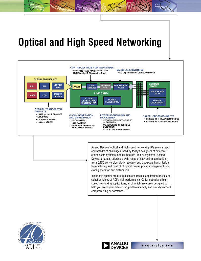
Analog Devices’ optical and high speed networking ICs solve a depth and breadth of challenges faced by today’s designers of datacom and telecom systems, optical modules, and subsystems. Analog Devices products address a wide range of networking applications from O/E/O conversion, clock recovery, and backplane transmission to monitoring and control of optical power, power management, and clock generation and distribution.
Inside this special product bulletin are articles, application briefs, and selection tables of ADI’s high performance ICs for optical and high speed networking applications, all of which have been designed to help you solve your networking problems simply and quickly, without compromising performance.
SWITCHCARD
BACKPLANEXCVR
OPTICAL TRANSCEIVER
PIN
LASER
TIA
LDD
LIMITINGAMP
CDR EYEOPENER
CDRSERDES
FRAMERASIC
BACKPLANEXCVR
CLOCKGENERATION/DISTRIBUTION
POWERSEQUENCING DIGITAL
CROSSPOINT
LINE CARD
XCVR
BACKPLANE SWITCHES • 3.2 Gbps SWITCH FOR REDUNDANCY
OPTICAL TRANSCEIVER CHIPSETS • 155 Mbps to 2.7 Gbps SFP • LX4, CWDM • 4� FIBRE CHANNEL • 10 Gbps XFP, X2
CLOCK GENERATION AND DISTRIBUTION • UP TO 655 MHz • <700 fs JITTER • VERY FINE PHASE AND
FREQUENCY TUNING
POWER SEQUENCING AND MANAGEMENT • SEQUENCE/SUPERVISE UP TO
12 SUPPLIES • 1% ACCURATE THRESHOLD
DETECTION • CLOSED-LOOP MARGINING
DIGITAL CROSS CONNECTS • 3.2 Gbps 34 � 34 ASYNCHRONOUS • 3.2 Gbps 34 � 34 SYNCHRONOUS
CONTINUOUS RATE CDR AND SERDES • BEST JTOL, JGEN, JTRAN OF ANY CDR • 12.5 Mbps to 2.7 Gbps and 10 Gbps

2
XFP Chipset and Reference Design Simplifies 10 Gbps Transceivers
Analog Devices introduces a 10 Gbps chipset that offers low power and the highest performance for receive sensitivity and transmit eye quality. Best in class jitter performance of the XFP signal conditioner increases robustness and minimizes interoperability issues. The companion reference design simplifies evaluation and speeds time to market. The reference design includes XFP boards, Gerber files, microcontroller software, and a GUI interface.
Features
• 9.9 Gbps to 11.1 Gbps data rate
• DFB, FP, or VCSEL operation
• Exceeds 20% SONET optical eye margin over temperature
• –19 dBm receive sensitivity
• Unparalleled jitter performance
• Supports full digital diagnostics
• Reference design includes Gerbers, SW, BOM, host board, and GUI interface
ADN2821 10 Gbps TIA
• –19 dBm sensitivity
• 700 nA integrated input noise
• 8.5 Gbps BW
• 3.3 V, 150 mW
• Supports APD or pin, in low cost TO-46 can
• RSSI power meter
• 0.7 mm 1.2 mm die size
• Samples in die or ROSA format
ADN2928 Family of XFP Signal Conditioners
• 9.9 Gbps to 11.1 Gbps
• Exceeds XFP requirements for jitter at OC192
• Lowest jitter generation: 6 mUI rms jitter
• Highest jitter tolerance: 0.6 UI p-p @ 10 MHz
• Lowest jitter transfer: 2.0 MHz OC192
• ADN2928 transceiver in 6 mm 6 mm BGA
• ADN2827/ADN2826 standalone transmit and receive functions in a 4 mm 4 mm LFCSP
See Page 3 for more details.
ADN2525 Differential Active Backmatch LDD
• 9.9 Gbps to 10.7 Gbps
• DFB, FP, or VCSEL operation
• Superior optical eye margins
• SONET >20% over temperature
• Ethernet >40% over temperature
• 750 mW typ (laser + LDD) over temperature
• Active load improves impedance matching
• 3.3 V operation, 3 mm 3 mm LFCSP
ADN2530 Differential Active Backmatch VCSEL Driver
• 9.9 Gbps to 10.7 Gbps
• 300 mW typ (laser + LDD) over temperature
• SONET eye margin exceeds 20%
• Crosspoint adjust feature
• Active load improves impedance matching
• 3.3 V operation, 3 mm 3 mm LFCSP
w w w . a n a l o g . c o m
>20% SONET optical eye margin
>20% SONET optical eye margin
APDs and pins in standard low cost TO-46 cans
XFP reference design available
Best in class for JGEN, JTRAN,
and JTOL, singles or duals
TOSA: DFB, FP, VCSEL
ROSA: Pin or APD
ADN2525ADN2530
LDDADN2926ADN2927ADN2829
XFPSIGNAL
CONDITIONER
ADuC7020ARM CORE
MICRO-CONTROLLER
RECEIVE
I2C®
TRANSMIT
ADN2821TIA

3
ADN2928 XFP Transceiver
• Range: 9.9 Gbps to 11.1 Gbps
• 6 mV input sensitivity
• Lowest jitter generation: 6 mUI rms jitter @ OC192
• Highest jitter tolerance: 0.6 UI p-p @ 10 MHz OC192
• Lowest jitter transfer: 2.0 MHz OC192
• Programmable LOS indicator
• LOL indicator
• Line side and client side loopback
• 750 mW power dissipation
• 6 mm 6 mm BGA
ADN2927 Transmit Signal Conditioner
• Equalizer with data recovery
• Range: 9.9 Gbps to 11.1 Gbps
• 375 mW power dissipation
• 4 mm 4 mm LFCSP
• Industry-leading jitter generation
ADN2926 Receive Signal Conditioner
• 3 mV input sensitivity limiting amp
• Range: 9.9 Gbps to 11.1 Gbps
• 375 mW power dissipation
• 4 mm 4 mm LFCSP
• Industry-leading jitter tolerance and transfer
10 Gbps XFP Signal Conditioner
The ADN2928 family of XFP signal conditioners are the latest to employ ADI’s patented performance-leading CDR architecture that maximizes both jitter tolerance and jitter transfer without compromise. The signal conditioner comes as either a bidirectional transceiver or as separate transmit and receive signal conditioner ICs, to accommodate different module layout preferences. The ADN2928 family offers unparalleled jitter performance exceeding XFP specs. Extra margin on jitter tolerance and jitter transfer specifications ensure a robust solution and solves interoperability issues.
ADN2928
TxOUTN
TxOUTP
RxLOS
TxINN
TxINP
SCK
SDA
RxLOCK
TxLOCK
RxOUTN
RxOUTP
ADN2928 XFP TRANSCEIVER
REFCLKP, NSYSTEM
LOOPBACK
RxINN
RxINP
CDR
PRBS
LINELOOPBACK
CML
CML
LIMAMP+ LOS
EQ
I2C
I/F
�4
PRBSCDR
ADN2926
ADN2927
ADN2928 Functional Block Diagram
JITTER TOLERANCE
0.1
1
10
100
MODULATION FREQUENCY (Hz)
JITT
ER
AM
PLI
TUD
E (U
I)
ADN2928
MASK
100 1k 10k 100k 1M 10M 100M
ADN2928 Jitter Tolerance
JITTER TRANSFER
–30
–25
–20
–15
–10
0
–5
10
5
100 1k 10k 100k 1M 10M 100M
MODULATION FREQUENCY (Hz)
JITT
ER
GA
IN (
dB)
ADN2928
MASK
ADN2928 Jitter TransferWith ADI CDRs you don’t have
to settle. You get the industry’s best JGEN, JTRAN, and JTOL.

4
4 Fibre Channel Chipset and Reference Design
Analog Devices introduces a 4 Fibre Channel chipset that offers very low power and very high performance for receive sensitivity and transmit eye quality. Pin-compatible LDDs serve either VCSEL or DFB/FP designs. The 4 chipset is also pin- and PC board-compatible with ADI’s SFP chipset. The companion reference design simplifies evaluation and speeds time to market.
Features
• Supports 1, 2, 4, and 1 GE rates
• DFB, FP, or VCSEL operation
• VCSEL optical eye margin exceeds 40%
• –18 dBm receive sensitivity (850 nm pin)
• Supports full SFF-8472 digital diagnostics
• Reference design includes Gerbers, SW, BOM, host board, and GUI interface
• Best in class performance for power, sensitivity, and eye quality
• All parts pin-compatible with SONET SFP design
ADN2882 4 Gbps TIA with –18 dBm Sensitivity
• 400 nA integrated input noise
• 3.2 Gbps BW
• 5 k transimpedance
• 3.3 V, 100 mW
• Optional RSSI power meter
• Samples in die or ROSA format
ADN2892 4 Gbps Limiting Amp with BW Select
• Bandwidth select function to support 1, 2 Fibre Channel
• 3.2 Gbps BW
• 3.3 V, 140 mW
• RSSI function works with any standard ROSA
• 3 mm 3 mm LFCSP
• LOS invert to support SFP and SFF
ADN2871 Single-Loop LDD
• Operation from 155 Mbps to 4.25 Gbps
• DFB, FP, or VCSEL operation
• Voltage setpoints simplify design
• Supports all SFF-8472 digital diagnostics requirements
• Pin-compatible with ADN2870 LDD
ADN2870 Dual-Loop LDD
• Operation from 155 Mbps to 4.25 Gbps
• Dual-loop eliminates need for temperature calibration and compensates for aging
• 3.3 V operation, 4 mm 4 mm LFCSP package
• Supports all SFF-8472 digital diagnostics
• Pin-compatible with ADN2871
ADN2880 3.3 Gbps TIA with –24 dBm Sensitivity
• 250 nA input referred noise
• 3.5 k transimpedance
• 75 mW power consumption
ADN2891 3.3 Gbps Limiting Amp with 3 mV Sensitivity
• RSSI function works with any standard ROSA
• Low power, 130 mW
• 3 mm 3 mm LFCSP
155 Mbps to 2.7 Gbps SFP reference design
also available
w w w . a n a l o g . c o m
Optical eye margin exceeds 40% with 4 Gbps VCSEL
TOSA: DFB, FP, VCSEL
ROSA: Pin or APD
ADN2870ADN2871
LDD
ADuC7020ARM CORE
MICROCONTROLLER
RECEIVE PATH
TRANSMIT PATH
ADN2880ADN2882
TIA
I2C
ADN2891ADN2892
LIMITING AMP
DIGITAL DIAGNOSTICS

5
ADL5317 APD Bias Controller
New Wide Dynamic Range APD Bias Controller and Current Monitor for Simpler, Low Noise Designs of APD Modules and Systems
With the advent of higher speed optical networks, transceivers often employ avalanche photodiodes (APDs) as the photodetector to improve receiver sensitivity and increase link reach. Traditionally, biasing and control of APDs in optical circuits have been challenging. To use the APD for received signal indication, it is necessary to maintain a constant responsivity (A/W). Reducing the nonlinear variations of the APD over temperature is accomplished by accurately controlling its avalanche multiplication factor by changing the bias voltage.
The new ADL5317 avalanche photodiode bias controller and current mirror has been specifically designed for wide dynamic range applications simplifying APD bias circuits. The ADL5317 accurately sets APD bias voltage ranging from 6 V to 72 V, and simultaneously enables highly accurate monitoring of photodiode current over a 6-decade range. The linear bias control interface of the ADL5317 allows for optical designers to use a fixed high voltage switcher, reducing supply decoupling and low-pass filtering requirements necessary in traditional APD biasing designs due to switching noise created by PWM-based dc-to-dc converters. Incorporating features such as overcurrent protection and overtemperature shutdown, the device is built for exceptional performance over temperature and ease of design for all APD modules and systems.
Features
• Stable, high voltage bias range, 6 V to 72 V
• Control APD bias using 3 V-compatible VSET interface
• Monitors photodiode current over 6-decade range
• Linearity 1% from 50 nA to 1 mA, 5% from 5 nA to 5 mA
• Overcurrent protection and over-temperature shutdown
• 16-lead, 3 mm 3 mm chip scale package (LFCSP)
w w w . a n a l o g . c o m
ADL5317VSET
N � VSET
TRANSLINEARLOG AMPSAD8304, ADL5306, ADL5310
TIAADN2821ADN2880ADN2882
FIXEDDC-TO-DC
BOOST
VSET
TE
MPEXTERNAL TEMP
CORRECTIONCONTROL
APD MONITORCONTROLLER
~ APD
DATA
~100 dBRSSI
6
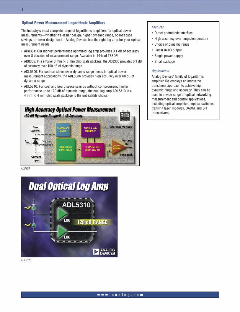
Optical Power Measurement Logarithmic Amplifiers
The industry’s most complete range of logarithmic amplifiers for optical power measurements—whether it’s easier design, higher dynamic range, board space savings, or lower design cost—Analog Devices has the right log amp for your optical measurement needs.
• AD8304: Our highest performance optimized log amp provides 0.1 dB of accuracy over 8 decades of measurement range. Available in 14-lead TSSOP.
• AD8305: In a smaller 3 mm 3 mm chip scale package, the AD8305 provides 0.1 dB of accuracy over 100 dB of dynamic range.
• ADL5306: For cost-sensitive lower dynamic range needs in optical power measurement applications, the ADL5306 provides high accuracy over 60 dB of dynamic range.
• ADL5310: For cost and board space savings without compromising higher performance up to 120 dB of dynamic range, the dual log amp ADL5310 in a 4 mm 4 mm chip scale package is the unbeatable choice.
Features
• Direct photodiode interface
• High accuracy over range/temperature
• Choice of dynamic range
• Linear-in-dB output
• Single power supply
• Small package
Applications
Analog Devices’ family of logarithmic amplifier ICs employs an innovative translinear approach to achieve high dynamic range and accuracy. They can be used in a wide range of optical networking measurement and control applications, including optical amplifiers, optical switches, transmit laser modules, OADM, and SFF transceivers.
w w w . a n a l o g . c o m
ADL5310
AD8304
7
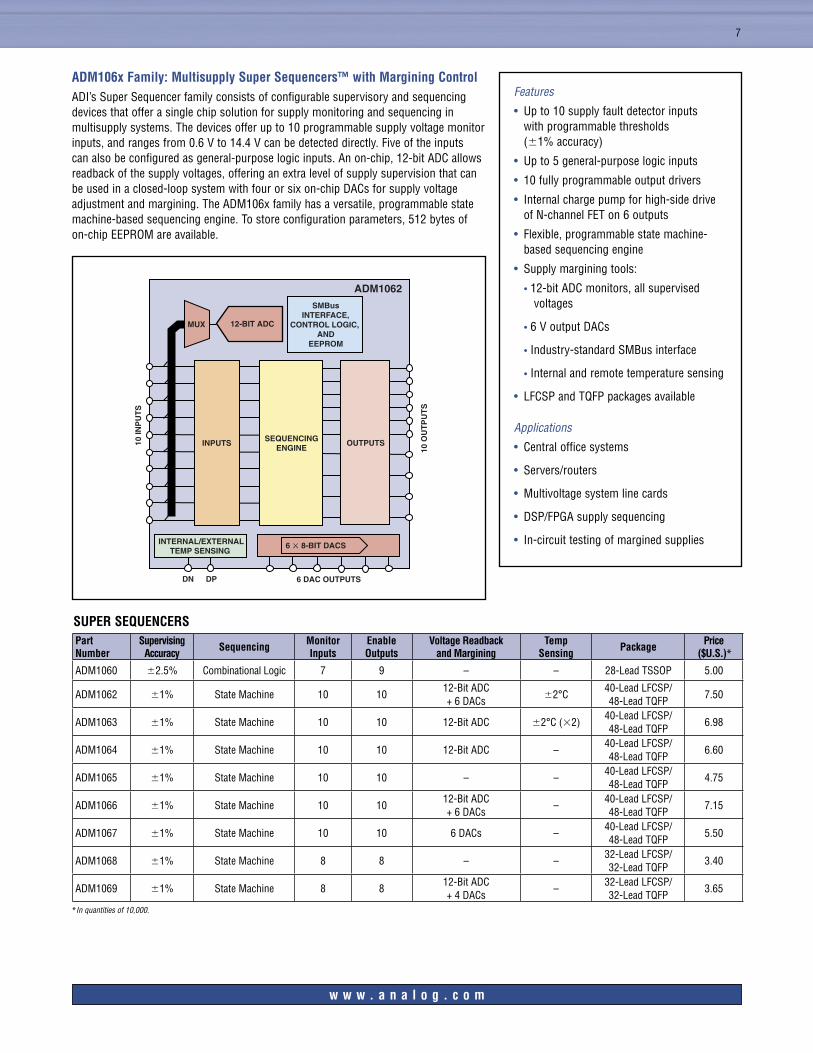
ADM106x Family: Multisupply Super Sequencers™ with Margining ControlADI’s Super Sequencer family consists of configurable supervisory and sequencing devices that offer a single chip solution for supply monitoring and sequencing in multisupply systems. The devices offer up to 10 programmable supply voltage monitor inputs, and ranges from 0.6 V to 14.4 V can be detected directly. Five of the inputs can also be configured as general-purpose logic inputs. An on-chip, 12-bit ADC allows readback of the supply voltages, offering an extra level of supply supervision that can be used in a closed-loop system with four or six on-chip DACs for supply voltage adjustment and margining. The ADM106x family has a versatile, programmable state machine-based sequencing engine. To store configuration parameters, 512 bytes of on-chip EEPROM are available.
Features
• Up to 10 supply fault detector inputs with programmable thresholds (1% accuracy)
• Up to 5 general-purpose logic inputs
• 10 fully programmable output drivers
• Internal charge pump for high-side drive of N-channel FET on 6 outputs
• Flexible, programmable state machine-based sequencing engine
• Supply margining tools:
• 12-bit ADC monitors, all supervised voltages
• 6 V output DACs
• Industry-standard SMBus interface
• Internal and remote temperature sensing
• LFCSP and TQFP packages available
Applications
• Central office systems
• Servers/routers
• Multivoltage system line cards
• DSP/FPGA supply sequencing
• In-circuit testing of margined supplies
SUPER SEQUENCERSPart Number
Supervising Accuracy Sequencing Monitor
InputsEnable Outputs
Voltage Readback and Margining
Temp Sensing Package Price
($U.S.)*
ADM1060 2.5% Combinational Logic 7 9 – – 28-Lead TSSOP 5.00
ADM1062 1% State Machine 10 1012-Bit ADC + 6 DACs
2°C40-Lead LFCSP/ 48-Lead TQFP
7.50
ADM1063 1% State Machine 10 10 12-Bit ADC 2°C (2)40-Lead LFCSP/ 48-Lead TQFP
6.98
ADM1064 1% State Machine 10 10 12-Bit ADC –40-Lead LFCSP/ 48-Lead TQFP
6.60
ADM1065 1% State Machine 10 10 – –40-Lead LFCSP/ 48-Lead TQFP
4.75
ADM1066 1% State Machine 10 1012-Bit ADC + 6 DACs
–40-Lead LFCSP/ 48-Lead TQFP
7.15
ADM1067 1% State Machine 10 10 6 DACs –40-Lead LFCSP/ 48-Lead TQFP
5.50
ADM1068 1% State Machine 8 8 – –32-Lead LFCSP/ 32-Lead TQFP
3.40
ADM1069 1% State Machine 8 812-Bit ADC + 4 DACs
–32-Lead LFCSP/ 32-Lead TQFP
3.65
*In quantities of 10,000.
w w w . a n a l o g . c o m
INPUTS SEQUENCINGENGINE
6 � 8-BIT DACS
OUTPUTS
6 DAC OUTPUTS
10 O
UT
PU
TS
10 IN
PU
TS
ADM1062
INTERNAL/EXTERNALTEMP SENSING
DPDN
12-BIT ADCMUX
SMBusINTERFACE,
CONTROL LOGIC, AND
EEPROM

Ampl
ifier
s
Part
Num
ber
Supp
ly V
olta
geR
ail-
to-
Rai
lM
icro
-pa
ckag
ing
A CL
Min
Band
wid
th @
ACL
(M
Hz)
Slew
R
ate
Dis
tort
ion
SFD
R @
Ba
ndw
idth
RL
Noi
se(n
V/√H
z)V O
S
(mV
Max
)I B
(mA
Max
)I S/
AMP
(mA
Typ)
Sing
leD
ual
Trip
leQ
uad
Dis
able
3 V
5 V
5
V
12 V
15
V
InO
utdB
cM
Hz
AD80
65AD
8066
••
••
•1
145
180
–88
11k
71.
510
pA
6.4
AD80
67•
••
••
860
500
–90
11k
71
10 p
A6.
4
Sele
ctio
n Ta
ble
Fibe
r O
ptic
Tra
nsim
peda
nce
Ampl
ifier
s
Part
Num
ber
Des
crip
tion
–3 d
B Ba
ndw
idth
(M
Hz)
Tran
sim
peda
nce
(k
)Su
pply
Vol
tage
(V
)Po
wer
Dis
sipa
tion
(mW
)Cu
rren
t Noi
se
(pA/
√Hz)
Ove
rloa
d Cu
rren
t (d
Bm)
Tota
l Jitt
er
(ps
p-p)
Out
put R
etur
n Lo
ss
(dB)
Die
Siz
e
(mm
m
m)
AD80
1515
5 M
bps
TIA
240
20+5
125
335
0—
—1
1
ADN
2880
3.3
Gbp
s TI
A2.
35
+3.3
758
3.25
—–2
00.
7
1.2
ADN
2882
4.25
Gbp
s TI
A3.
24
+3.3
7510
——
–20
0.7
1
.2
ADN
2821
10 G
bps
TIA
9.5
10+3
.315
012
3.25
5–1
20.
7
1.2
Fibe
r O
ptic
Lim
iting
Am
plifi
ers
Part
Num
ber
Des
crip
tion
Dat
a R
ate
(G
bps)
Supp
ly V
olta
ge
(V)
Inpu
t Sen
sitiv
ity
(mV
p-p)
Pow
er D
issi
patio
n (m
W)
Out
put L
evel
s
(mV
p-p
diff)
LOS
Jitte
r
(rm
s)Sq
uelc
hBW
Sel
ect
RSS
IPa
ckag
e
ADN
2891
3.3
Gbp
s Li
miti
ng A
mp
3.2
3.3
314
570
03
mV
to 4
5 m
V2.
4Ye
sN
oYe
s3
mm
3
mm
LFC
SP
ADN
2892
4.25
Gbp
s Li
miti
ng A
mp
4.25
3.3
316
070
03
mV
to 4
5 m
V5
No
Yes
Yes
3mm
3
mm
LFC
SP
Fibe
r O
ptic
Las
er D
iode
Dri
vers
Part
Num
ber
Des
crip
tion
Dat
a R
ate
(G
bps)
Su
pply
Vol
tage
(V
)La
ser
Bias
Cu
rren
t (m
A)Si
ngle
-End
ed/
Diff
eren
tial
Mod
ulat
ion
Curr
ent
(mA)
Ris
e/Fa
ll Ti
me
(p
s)D
ual L
oop
MSA
Com
plia
nce
Pack
age
ADN
2848
1.25
Gbp
s Du
al-L
oop
LDD
1.25
3.3
100
Both
8080
Yes
SFF
5 m
m
5 m
m L
FCSP
ADN
2841
2.5
Gbp
s D
ual-L
oop
LDD
2.7
510
0Bo
th80
80Ye
sSF
F5
mm
5
mm
LFC
SP
ADN
2847
3.3
Gbp
s D
ual-L
oop
LDD
3.3
3.3
100
Both
8080
Yes
SFF
5 m
m
5 m
m L
FCSP
ADN
2870
4.25
Gbp
s D
ual-L
oop
LDD
3.3
3.3
100
Both
9060
Yes
SFP-
SFF-
8472
4 m
m
4 m
m L
FCSP
ADN
2871
4.25
Gbp
s Si
ngle
-Loo
p LD
D3.
33.
310
0Bo
th90
60N
oSF
P-SF
F-84
724
mm
4
mm
LFC
SP
ADN
2525
10 G
bps
Diff
eren
tial L
DD
10.7
3.3
100
Diff
eren
tial
8024
No
XFP,
Xen
pak,
X2,
MSA
-300
3 m
m
3 m
m L
FCSP
ADN
2530
10 G
bps
VCSE
L D
river
10.7
3.3
22D
iffer
entia
l22
24N
oXF
P, X
enpa
k, X
2, M
SA-3
003
mm
3
mm
LFC
SP
ADN
2830
CW L
aser
Driv
er—
520
0Si
ngle
-End
ed—
——
—5
mm
5
mm
LFC
SP
Cloc
k an
d D
ata
Rec
over
y IC
s
Part
Num
ber
Des
crip
tion
Supp
ly V
olta
ge
(V)
Dat
a R
ate
(G
bps)
Pow
er D
issi
patio
n
(mW
)In
put S
ensi
tivity
(m
V p-
p)Ji
tter T
oler
ance
(U
l p-p
)Ji
tter T
rans
fer
Jitte
r Gen
erat
ion
(m
UI r
ms)
Lim
iting
Am
pR
ate
Pack
age
AD80
052
Mbp
s CD
R+5
/–5.
20.
052
650
800.
9 @
65
kHz
52 k
Hz7
NoSi
ngle
20-L
ead
SOIC
AD80
715
5 M
bps
CDR
50.
155
170
21.
0 @
65
kHz
92 k
Hz5
Yes
Sing
le16
-Lea
d SO
IC
AD80
862
2 M
bps
CDR
50.
622
400
40.
6 @
250
kHz
333
kHz
7Ye
sSi
ngle
16-L
ead
SOIC
ADN2
807
155
Mbp
s/62
2 M
bps
CDR
3.3
0.15
5/0.
622
540
41.
0 @
250
kHz
140
kHz
@ O
C12
1Ye
sM
ulti
7 m
m
7 m
m L
FCSP
ADN2
811
2.5
Gbps
/2.7
Gbp
s CD
R3.
32.
5/2.
754
04
1.0
@ 1
MHz
590
kHz
@ O
C48
2Ye
sDu
al7
mm
7
mm
LFC
SP
ADN2
812
12.3
Gbp
s to
2.7
Gbp
s CD
R3.
312
.3 to
2.7
750
61.
0 @
1 M
Hz49
0 kH
z @
OC4
81
Yes
Cont
inuo
us5
mm
5
mm
LFC
SP
ADN2
813
12.3
Gbp
s to
1.2
5 Gb
ps C
DR
3.3
12.3
to 1
.25
425
61.
0 @
637
kHz
71 k
Hz @
OC1
21
Yes
Cont
inuo
us5
mm
5
mm
LFC
SP
ADN2
814
12.3
Mbp
s to
675
Mbp
s CD
R 3.
312
.3 to
0.6
7542
56
1.0
@ 2
50 k
Hz71
kHz
@ O
C12
1Ye
sCo
ntin
uous
5 m
m
5 m
m L
FCSP
ADN2
815
12.3
Gbp
s to
1.2
5 Gb
ps C
DR
3.3
12.3
to 1
.25
375
501.
0 @
250
kHz
71 k
Hz @
OC1
21
NoCo
ntin
uous
5 m
m
5 m
m L
FCSP
ADN2
816
12.3
Mbp
s to
675
Mbp
s CD
R 3.
312
.3 to
0.6
7537
550
1.0
@ 2
50 k
Hz71
kHz
@ O
C12
1No
Cont
inuo
us5
mm
5
mm
LFC
SP
ADN2
819
155
Mbp
s to
2.7
Gbp
s CD
R3.
32.
754
04
1.0
@ 1
MHz
590
kHz
@ O
C48
2Ye
sM
ulti
7 m
m
7 m
m L
FCSP
ADN2
928
9.9
Gbps
to 1
1.3
Gbps
TxR
x Si
gnal
Con
ditio
ner
3.3/
1.8
9.9
to 1
1.1
750
61.
0 @
1 M
Hz2
MHz
@ O
C192
6Ye
sCo
ntin
uous
6 m
m
6 m
m B
GA
ADN2
927
9.9
Gbps
to 1
1.3
Gbps
Tra
nsm
it Si
gnal
Con
ditio
ner
3.3/
1.8
9.9
to 1
1.1
375
61.
0 @
1 M
Hz2
MHz
@ O
C192
6Ye
sCo
ntin
uous
4 m
m
4 m
m L
FCSP
ADN2
926
9.9
Gbps
to 1
1.3
Gbps
Rec
eive
Si
gnal
Con
ditio
ner
3.3/
1.8
9.9
to 1
1.1
375
61.
0 @
1 M
Hz2
MHz
@ O
C192
6Ye
sCo
ntin
uous
4 m
m
4 m
m L
FCSP

Anal
og-t
o-D
igita
l Con
vert
ers1
Part
Num
ber
Res
olut
ion
(B
its)
Thro
ughp
ut R
ate
(k
SPS)
Num
ber
of A
nalo
g In
puts
Pow
er S
uppl
y
Volta
ge (
V NO
M)
Pow
er D
issi
patio
n
(mW
Max
)R
efer
ence
(I
nt/E
xt)
Des
crip
tion
AD76
7418
1,00
01
Sing
le (
5)12
5In
t/Ext
18-B
it, 1
MSP
S Pu
lSAR
® A
DC
AD76
2116
Up
to 3
,000
1Si
ngle
(2.
5)10
0In
t16
-Bit,
1 L
SB IN
L, 3
MSP
S Pu
lSAR
AD
C
AD76
64/A
D76
6516
570
1Si
ngle
(5)
115/
107
Ext
16-B
it, 5
70 k
SPS,
Pul
SAR
AD
C AD
C
AD76
7116
1,00
01
Sing
le (
5)12
5Ex
t16
-Bit,
1 M
SPS,
Bip
olar
Pul
SAR
AD
C
AD76
7616
500
1Si
ngle
(5)
74Ex
t16
-Bit,
500
kSP
S, D
iffer
entia
l Pul
SAR
AD
C
AD78
6514
350
4Si
ngle
(5)
130
Ext
14-B
it, 4
-Cha
nnel
Sim
ulta
neou
s Sa
mpl
ing
Para
llel A
DC
AD74
8414
3,00
01
Sing
le (
2.3
to 5
.25)
90In
t14
-Bit,
3 M
SPS
Para
llel A
DC
AD78
5614
285
8Si
ngle
(5)
12.5
Int
14-B
it, 8
-Cha
nnel
, 285
kSP
S Se
rial A
DC
AD74
9012
1,00
016
Sing
le (
2.7
to 5
.25)
6Ex
t12
-Bit,
16-
Chan
nel,
1 M
SPS
Seria
l AD
C w
ith S
eque
ncer
AD79
2712
200
8Si
ngle
(2.
7 to
5.2
5)3.
6Ex
t12
-Bit,
8-C
hann
el, S
eria
l AD
C w
ith S
eque
ncer
Dig
ital-
to-A
nalo
g Co
nver
ters
Part
Num
ber
Res
olut
ion
(Bits
)N
umbe
r of
DAC
s In
put
Out
put
Pow
er S
uppl
yPa
ckag
eD
escr
iptio
n
AD53
7914
40Se
rial/P
aral
lel
V OU
T (B
ipol
ar)
12
V a
nd 3
V o
r 5
VCS
PBG
A-10
814
-Bit,
40-
Chan
nel,
Bipo
lar
V OU
T D
AC
AD53
8014
40SP
I®/I2 C
®/P
aral
lel
V OU
T2.
7 V
to 5
.5 V
LQFP
-100
14-B
it, 4
0-Ch
anne
l, Si
ngle
-Sup
ply
DAC
AD55
3214
32Se
rial 3
-Wire
(SP
I)V O
UT
(Bip
olar
)+5
V,
15 V
CSPB
GA-
7414
-Bit,
32-
Chan
nel,
Seria
l DAC
AD55
32H
S14
32Se
rial 3
-Wire
(SP
I)V O
UT
(Bip
olar
)+5
V,
15 V
CSPB
GA-7
414
-Bit,
32-
Chan
nel,
Fast
Ser
ial D
AC
AD55
3514
32SP
IV O
UT
200
V, 5
VCS
PBGA
-108
14-B
it, 3
2-Ch
anne
l, 20
0 V
DAC
AD53
8214
32SP
I/I2 C
/Par
alle
lV O
UT
2.7
V to
5.5
VLQ
FP-1
0014
-Bit,
32-
Chan
nel,
Sing
le-S
uppl
y DA
C
AD53
9014
16SP
I/I2 C
V OU
T2.
7 V
to 5
.5 V
LFCS
P-64
, LQF
P-52
14-B
it, 1
6-Ch
anne
l, Si
ngle
-Sup
ply
DAC
AD53
9214
8SP
I/I2 C
V OU
T2.
7 V
to 5
.5 V
LF
CSP-
64, L
QFP-
5214
-Bit,
8-C
hann
el, S
ingl
e-Su
pply
DAC
AD78
4114
8Pa
ralle
lV O
UT
(Bip
olar
)
15 V
PQFP
-44
14-B
it, 8
-Cha
nnel
, Par
alle
l DAC
AD55
1612
16Se
rial 3
-Wire
(SP
I)V O
UT
(Bip
olar
)
5 V,
15
VCS
PBGA
-74
12-B
it, 1
6-Ch
anne
l, Se
rial D
AC
AD53
2812
8Se
rial 3
-Wire
(SP
I)V O
UT
2.7
V to
5.5
V
TSSO
P-16
12-B
it, 8
-Cha
nnel
, Ser
ial S
ingl
e-Su
pply
DAC
Mic
roCo
nver
ters
®
Part
Num
ber
ADC
DAC
MCU
Flas
h/EE
Cod
ePa
ckag
eSp
ecia
l Fea
ture
sAD
uC70
20/A
DuC
7021
/AD
uC70
225-
/8-/
10-C
hann
el, 1
2-Bi
tM
ultic
hann
el, 1
2-Bi
t16
-Bit/
32-B
it R
ISC
62 k
B, 3
2 kB
CSP-
40AR
M7T
DM
I Cor
e, S
mal
l Foo
tprin
tAD
uC81
28-
Chan
nel,
12-B
itD
ual,
12-B
it12
-Clo
ck 8
052
8 kB
PQFP
-52,
CSP
-56
5
s AD
CAD
uC81
46-
Chan
nel,
12-B
itD
ual,
12-B
it12
-Clo
ck 8
052
8 kB
TSSO
P-28
Smal
l, Lo
w C
ost
ADuC
831
8-Ch
anne
l, 12
-Bit
Dua
l, 12
-Bit
+ D
ual P
WM
12-C
lock
805
262
kB
PQFP
-52,
CSP
-56
Big
Mem
ory
Upg
rade
to A
DuC
812
ADuC
832
8-Ch
anne
l, 12
-Bit
Dua
l, 12
-Bit
+ D
ual P
WM
12-C
lock
805
262
kB
PQFP
-52,
CSP
-56
Sam
e as
AD
uC83
1, b
ut w
ith P
LL C
lock
ADuC
841
8-Ch
anne
l, 12
-Bit
Dua
l, 12
-Bit
+ D
ual P
WM
12-C
lock
805
262
kB
PQFP
-52,
CSP
-56
Fast
Cor
e U
pgra
de to
AD
uC83
1 (n
o PL
L)AD
uC84
28-
Chan
nel,
12-B
itD
ual,
12-B
it +
Dua
l PW
M12
-Clo
ck 8
052
62 k
BPQ
FP-5
2, C
SP-5
6Fa
st C
ore
Upg
rade
to A
DuC
832
(with
PLL
)Co
ntro
l and
Mon
itori
ng IC
s Pa
rt N
umbe
rPe
rfor
man
cePa
ckag
e
Des
crip
tion
AD83
0416
0 dB
Ran
ge (
100
nA to
10
mA)
TSSO
P-14
Loga
rithm
ic A
mpl
ifier
with
Pho
todi
ode
Inte
rfac
eAD
8305
100
dB R
ange
(10
nA
to 1
mA)
LFCS
P-16
Lo
garit
hmic
Am
plifi
er w
ith P
hoto
diod
e In
terf
ace
ADL5
306
60 d
B R
ange
(10
0 nA
to 1
00 m
A)LF
CSP-
16Lo
garit
hmic
Am
plifi
er w
ith P
hoto
diod
e In
terf
ace
ADL5
310
120
dB R
ange
(3
nA to
3 m
A)LF
CSP-
24D
ual L
ogar
ithm
ic A
mpl
ifier
with
Pho
todi
ode
Inte
rfac
eAD
L531
712
0 dB
Ran
ge (5
nA
to 5
mA)
Cur
rent
Mon
itorin
g, A
PD B
ias
Rang
e fro
m 6
V to
72
VLF
CSP-
16Av
alan
che
Phot
odio
de B
ias
Cont
rolle
r an
d W
ide-
Ran
ge C
urre
nt M
onito
r
ADN
8810
Curr
ent O
utpu
t (0
to 2
50 m
A)LF
CSP-
24Pr
ogra
mm
able
Pre
cisi
on C
urre
nt S
ourc
e fo
r Tu
nabl
e La
sers
ADN
8830
Low
Noi
se: <
0.5
% T
EC C
urre
nt R
ippl
eLF
CSP-
32Th
erm
oele
ctric
Coo
ler
Cont
rolle
rAD
N88
31Lo
w N
oise
: <0.
05%
TEC
Cur
rent
Rip
ple
LFCS
P-32
Hig
h Pr
ecis
ion
Ther
moe
lect
ric C
oole
r Co
ntro
ller
Dig
ital C
ross
poin
t Sw
itche
s Pa
rt N
umbe
rPe
rfor
man
cePa
ckag
e
F
unct
ion
AD81
50
1.5
Gbp
s LQ
FP-1
8433
1
7 D
igita
l Cro
sspo
int S
witc
hAD
8151
3.
2 G
bps
LQFP
-184
33
17
Dig
ital C
ross
poin
t Sw
itch
AD81
52
3.2
Gbp
s BG
A-25
634
3
4 D
igita
l Cro
sspo
int S
witc
hAD
XS34
3.
2 G
bps
EBG
A-30
434
3
4 Sy
nchr
onou
s Cr
ossp
oint
Sw
itch
AD81
593.
2 G
bps
TQFP
-100
Qua
d 2:
1 M
ux/D
emux
1 Parti
al li
stin
g.

10
Single-Supply, 16-Channel and 8-Channel DACs Pack Performance and Functionality into a 9 mm 9 mm CSPHigh channel count DACs are ideally suited for power amplifier control, instrumentation, control systems, and level setting, or for any application where board space is at a premium. Only one supplier provides the channel density, high resolution, high accuracy, and wide range of features demanded by these challenging designs.
Analog Devices’ new family of high density DACs provides the channel density, high resolution, high accuracy, and wide range of features demanded by these challenging designs. The AD5390 features the industry’s first 16-channel, 14-bit resolution voltage-output DAC operating from either a single 5 V or 3 V power supply. A 12-bit version (AD5391) and an 8-channel, 14-bit version (AD5392) are also available. All devices are offered in a 64-lead LFCSP and a 52-lead LQFP.
These devices contain on-chip, low drift references (2.5 V and 1.25 V), eliminating the need for an external reference IC, and reducing cost and board space. The parts also include user-programmable offset and gain for digital range adjustment and system calibration. They offer high accuracy and increased functionality, including a boost mode that allows the parts to achieve faster settling times, and an LDAC (load DAC) function that allows simultaneous update of all DAC outputs.
ADI’s high density DACs offer rail-to-rail outputs at a 5 V or 3 V supply voltage. In addition, they offer the choice of SPI and I2C serial interfaces, and are pin-for-pin compatible, allowing a designer the option of generating different grades of end product as appropriate. Visit our website for more information on samples and evaluation boards at www.analog.com/denseDACs.
Applications
• Optical line cards
• Variable optical attenuators
• Instrumentation and industrial control
• Power amplifier control
• Level setting
• Control systems
• Medical equipment
Part Number Channels Resolution (Bits) INL (LSB) Power Supply (V) Package Price ($U.S.)AD5390-5/AD5390-3 16 14 4 5/3 64-Lead LFCSP, 52-Lead LQFP 23.90AD5391-5/AD5391-3 16 12 1 5/3 64-Lead LFCSP, 52-Lead LQFP 19.90AD5392-5/AD5392-3 8 14 4 5/3 64-Lead LFCSP, 52-Lead LQFP 14.90
New Single-Supply, 40-Channel DAC Packs Performance and Functionality into 10 mm 10 mm CSPBGAHigh channel count DACs are ideally suited for instrumentation, level setting, laser control, or any application where board space is at a premium.
The AD5384 is an extension of the AD5380 and AD5390 family of high density DACs. The new AD5384 features the industry’s first 40-channel, 14-bit resolution voltage-output DAC with a 10 mm 10 mm footprint. This device operates from either a single 5 V or 3 V power supply and provides rail-to-rail outputs. It offers a choice of SPI and I2C serial interfaces.
The AD5384 contains on-chip, low drift references (2.5 V and 1.25 V) that eliminate the need for an external reference IC, reducing cost and board space. The part also includes user-programmable offset and gain per channel for digital range adjustment and system calibration. It offers high accuracy and increased functionality, including a boost mode that allows the parts to achieve faster settling times, a monitor mode that multiplexes the analog outputs to a single pin, and an LDAC function that allows simultaneous update of all DAC outputs. For more information, visit www.analog.com/denseDACs.
Part Number Channels Bits INL
(LSB)Power
Supply (V) Package Price ($U.S.)
AD5384-5/AD5384-3 40 14 4 5/3 CSPBGA-100 49.50
AD5380-5/AD5380-3 40 14 4 5/3 LQFP-100 49.50
AD5381-5/ AD5381-3 40 12 1 5/3 LQFP-100 39.50
w w w . a n a l o g . c o m / d e n s e D A C s

11
High Voltage, 32-Channel DAC in 15 mm 15 mm Footprint for MEMS Mirror ControlThe AD5535 is a 32-channel, 14-bit DAC with on-chip high voltage output amplifiers. This device is ideally suited for the control of MEMS devices in optical crosspoint switches or variable optical attenuators (VOAs). The AD5535 is guaranteed monotonic to 14 bits. Its output voltage range is programmable via the REFIN pin, e.g., the output range is 0 V to 50 V with REFIN = 1 V and is 0 V to 200 V with REFIN = 4 V. Each output amplifier can source 700 A, ideal for the deflection and control of optical MEMS mirrors. Each amplifier has a gain of 50 and is driven from a 14-bit DAC whose output range varies from 0 to VREF depending on the code loaded to the relevant DAC register. The selected DAC register is written to via the 3-wire SPI interface, which operates at clock rates up to 30 MHz.
The AD5535 operates with AVCC = 5 V, DVCC = 3 V to 5 V, V– = –5 V, V+ = +5 V, and VPP = 210 V. It is packaged in a 124-CSPBGA package with a footprint of 15 mm 15 mm. For more information, visit www.analog.com/AD5535.
Need More Channels? We’ve Added a 16-Channel Mux with Sequencer to the Lowest Power, 1 MSPS, 12-Bit ADC.In the optical communications sector there is a major demand for increased channel count on ADCs. With this increased channel count is a need to be able to select between channels and program various channel sequences for the ADC to convert.
The AD7490 is a 12-bit, 1 MSPS, low power successive approximation ADC. The AD7490 features 16 single-ended analog inputs with a channel sequencer to allow a preprogrammed selection of channels to be converted sequentially. These channels can be selected by programming the relevant bits in the shadow register.
The AD7490 operates from a single 2.7 V to 5.25 V supply, and contains the VDRIVE function, allowing the serial interface to connect directly to either 3 V or 5 V processor systems independent of VDD. The analog input for the part can be selected to be 0 to REFIN or 0 to 2 REFIN with either straight binary or twos complement output coding. The AD7490 features a number of shutdown modes to maximize further power efficiency at lower throughput rates and is available now for $5.95 in 1k quantities.
Part Number Resolution
(Bits)Throughput
(kSPS)Power
(mW Max)Channels
AD7490 12 1,000 12.5 16AD7928 12 1,000 13.5 8AD7927 12 200 7.5 8AD7918 10 1,000 13.5 8AD7908 8 1,000 13.5 8AD7924 12 1,000 13.5 4AD7923 12 200 7.5 4AD7914 10 1,000 13.5 4AD7904 8 1,000 13.5 4
Features
• Fast throughput rate: 1 MSPS
• Specified for VDD of 2.7 V to 5.25 V
• 5.4 mW max at 1 MSPS with 3 supplies
• 12.5 mW max at 1 MSPS with 5 V supplies
• 16 (single-ended) inputs with channel sequencer
• Available in 28-TSSOP and 32-LFCSP packages
Applications
• Optical networking
• Instrumentation
• Data acquisition
w w w . a n a l o g . c o m / A D 5 5 3 5
IOL
IOH
1.6VTO
OUTPUTPIN CL
25pF
200 A
200 A
Load Circuit for Digital Output Timing Specifications
REFLECTOR
MEMS MIRRORS
OPTICAL FIBER
OPTICAL COUPLER
ACTUATORS
MUXSENSORS
DA
C
AD
C
AD5535
MUXADC
LOGAMPS
ADG732
PHOTO-DIODES
AD7671
DSP OR MICROCONTROLLER

12
ADSX34 Synchronous Crosspoint SwitchDifficult signal integrity, density, and low power design challenges are inherent in packet and cell-based switching and routing systems that drive enterprise/SAN and access and metro networks. Network equipment suppliers must address these challenges and develop unified, low cost, flexible multiprotocol switching solutions that can scale from enterprise to edge aggregation and core applications.
Applications
• Packet and cell-based switching and routing systems that drive enterprise/SAN and access and metro networks
The ADSX34 is the industry’s lowest power, synchronous crosspoint switch. The new chip is designed to solve difficult signal integrity, density, and low power design challenges, while enabling designers to develop equipment on time, on budget, and with system flexibility. At 5 W, the ADSX34 consumes one-third the power of comparable products on the market. The device, part of ADI’s Xstream™ family of low power crosspoint switches, integrates 34 SERDES channels, equalization, and other features, making it a complete solution for high speed networks. The device’s low power consumption reduces the need for expensive, space-consuming heat sinks and other thermal management components.
Feature-Rich Crosspoint Switch
The ADSX34 Is a Feature-Rich, Complete Crosspoint Solution that Offers:
• 34 highly integrated channels, each operating at up to 3.2 Gbps
• Per channel programmable receive equalization and transmit pre-emphasis that allows equalization over 30 inches of FR4 material, including two standard high density differential connectors
• Support for time slots of 24 to 4,000 characters
• Per channel time slot synchronization FIFOs absorb up to 128 bytes of variation in packet arrival times, simplifying system timing
Flexibility Is Key for Networking Applications
The versatility of the ADSX34 makes it ideal for multiservice environments. The ADSX34 can switch any form of packet or cell-based traffic, including ATM (asynchronous transfer mode), Ethernet, Fibre Channel, serial rapid I/O, or IP (Internet protocol), eliminating the need to design multiple switches for different protocols.
w w w . a n a l o g . c o m

13
AD8159 Four-Lane 2:1 Multiplexer/DemultiplexerSystem designers of today’s modular communications face an increasingly difficult challenge of supplying high reliability systems and reducing downtime. One of the most effective methods to achieve this is by designing built-in redundancy.
The AD8159 is the most cost-effective method to offer redundant switching within a modular communications system. The AD8159 is tailored to support redundancy on both the backplane and the line interface. The device has unicast and bicast capability, so it can be configured to support either 1+1 or 1:1 redundancy.
The AD8159 is a member of Analog Devices’ Xstream line of digital crosspoints. It is an asynchronous, protocol agnostic, four-lane 2:1 multiplexer/demultiplexer with a total of 12 differential LVPECL-/CML-compatible inputs and 12 differential CML outputs. The integrated receive equalization and transmit pre-emphasis allow for directly driving legacy and next generation backplanes. The operation of this product is optimized for NRZ signaling with data rates up to 3.2 Gbps per lane.
The AD8159 is equipped with Analog Devices’ proprietary crossover transceiver, which allows for swapping transmit and receive pairs to greatly ease layout and compatibility issues.
Features
• 4-lane 2:1 mux/1:2 demux
• Quad- or single-lane switching
• Port-level loopback
• Programmable input equalization
• Programmable output pre-emphasis
• Asynchronous operation
• Simple control interface
• 0 Gbps to 3.2 Gbps data rate
• 1 W total power dissipation
• 3.3 V power supply
• LVPECL-/CML-compatible inputs
• 100-lead TQFP package
Applications
• Switch fabric redundancy
• Backplane equalization
• Loopback diagnostics
• Fan-in/out
• Ethernet
• Fibre Channel
• Infiniband
• SONET/SDH
w w w . a n a l o g . c o m
2:1
1:2
TRANSIT
PRE-EMPHASIS
TRANSIT
PRE-EMPHASIS
I/O
CROSS-OVER
SWITCH
QUAD
2:1 MULTIPLEXER/
1:2 DEMULTIPLEXER
IN_A[0:3]
IN_B[0:3]
OUT_A[0:3]
OUT_B[0:3]
OUT_C[0:3]
IN_C[0:3]
IN_C[0:3]
OUT_C[0:3]
LB_ALB_BLB_CPE_A[0:1]PE_B[0:1]PE_C[0:1]EQ_AEQ_BEQ_CSEL [0:3]BICASTREVERSE_C
CONTROL
LOGIC
RECEIVE
EQUALI-�A TION
RECEIVE
EQUALI-�A TION
EQ
EQ
EQ
14
In today’s digital and mixed-signal electronic systems, clocking is an important consideration for overall system performance. The ability to generate clocks at specific rates with low jitter is vital to the proper functioning of analog-to-digital converters (ADCs) and digital-to-analog converters (DACs). This is because uncertainty in the time domain, characterized as jitter, translates to uncertainty in amplitude, reducing the achievable noise floor and corresponding figures of merit, such as signal-to-noise ratio (SNR) and bit error rate (BER). Other challenges faced in generating clocks include fre-quency accuracy, frequency resolution, and the ability to introduce timing skew or phase delay between different channels.
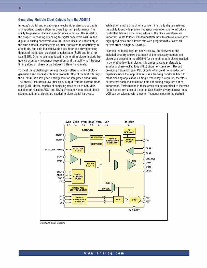
To meet these challenges, Analog Devices offers a family of clock generation and clock distribution products. One of the first offerings, the AD9540, is a low jitter clock generation integrated circuit (IC). The AD9540 features a low jitter clock output from its current mode logic (CML) driver, capable of achieving rates of up to 655 MHz, suitable for clocking ADCs and DACs. Frequently, in a mixed-signal system, additional clocks are needed to clock digital hardware.
While jitter is not as much of a concern in strictly digital systems, the ability to provide precise frequency resolution and to introduce controlled delays on the rising edges of the clock waveform are important. What follows will demonstrate how to achieve a low jitter, high speed clock and a lower rate with programmable skew, all derived from a single AD9540 IC.
Examine the block diagram shown below. An overview of the included circuitry shows that many of the necessary component blocks are present in the AD9540 for generating both clocks needed. In generating low jitter clocks, it is almost always preferable to employ a phase-locked loop (PLL) circuit of some sort. Beyond providing frequency gain, PLL circuits offer great noise reduction capability since the loop filter acts as a tracking bandpass filter. In most clocking applications a single frequency is required, therefore, parameters such as acquisition time and tuning range are not of importance. Performance in these areas can be sacrificed to increase the noise performance of the loop. Specifically, a very narrow range VCO can be selected with a center frequency close to the desired
AVDD AGND DVDD DGND VCML VCP CP_RSET
CPREF, AMP
REFIN
REFIN
CLK1
CLK1
CHARGEPUMP
PHASE/FREQUENCYDETECTOR
AD9540
M DIVIDER
N DIVIDER
DIVIDER1, 2, 4, 8
SYNC_IN/STATUS SYNC, PLLLOCK
SCLK
SDI/O
SDO
CS
SERIALCONTROL
PORT
TIMING ANDCONTROL LOGIC
CLK2
CP
CLK2
DRV_RSET
OUT0CML
OUT0
VCML
CLK
DIVCLK
S2
S1
S0
PHASE/FREQUENCY
PROFILESDDS
IOUT
IOUTDAC
DAC_RSET
4810
14
Functional Block Diagram
Generating Multiple Clock Outputs from the AD9540
w w w . a n a l o g . c o m

15
clock rate. As the tuning range is reduced, the gain coefficient for the VCO is reduced, and the phase noise of the VCO itself is thereby reduced. Also, the loop filter bandwidth is a concern for designers in that there is a trade-off associated with this parameter. Note that the wider the loop bandwidth, the faster the acquisition and lock time of a loop but the more noise from the reference and phase frequency detector itself gets fed through the loop. In the case of a clocking application, this trade-off can be made to achieve narrow loop bandwidths, sacrificing settling time in favor of noise suppression through the loop.
The digital clock, which requires precise frequency and adjustable phase, can be generated from the direct digital synthesizer (DDS) portion of the device. The DDS on the AD9540 offers 48-bit frequency tuning resolution (1.42 MHz, given the maximum clock rate of 400 MHz) and 10-bit phase adjustment (0.351 deg). The output of a DDS is a reconstructed sine wave, so two additional external circuits are required. First, a bandpass filter at the desired clock rate needs to be applied to the reconstructed sine wave. This
removes all sampling artifacts from the output spectrum as well as broadband noise that has infected the DAC output signal. Second, to achieve the required slew rates for most clock circuits, an external comparator needs to be inserted into the clock signal path. One excellent choice, used for this example, is the ADCMP563.
A simplified block diagram for the resultant circuit is shown below. The following are notes to the diagram that may not be readily apparent from the drawing. First, inputs Clock1/Clock1 are shorted to Clock2/Clock2. The device is programmed so that the CML driver gets its input from the undivided input from Clock 1, but the DDS is clocked by the divided output (622 MHz divided by 2 = 311 MHz). The two output clocks are shown at OUT0 (the low jitter 622 MHz clock) and OUT1 (the phase programmable auxiliary clock). Edge skew (or time delay) in the auxiliary clock is accomplished by programming a phase offset into the DDS, which will change the relative point in time for the complementary input crossing at the comparator.
w w w . a n a l o g . c o m
Solution Configuration
VCO
REFIN
CHARGEPUMP
PHASE/FREQUENCYDETECTOR
M DIVIDER
N DIVIDER
DIVIDER1, 2, 4, 8
PLLLOCK
CLK2
CP622 MHz
CLK2
DRV_RSETOUT0CML
VCML
S2
S1
S0
PHASE/FREQUENCY
PROFILESDDS
IOUT
IOUT
DAC
DAC_RSET
4810
14
REFIN
OUT1
OUT1
OUT0
LOW-PASS (LOOP) FILTER
BANDPASSFILTER
ADCMP563
CLK2
CLK1
CLK2

Worldwide HeadquartersOne Technology Way P.O. Box 9106 Norwood, MA 02062-9106 U.S.A. Tel: 781.329.4700 (1.800.262.5643, U.S.A. only) Fax: 781.326.8703
Analog Devices, Inc. Europec/o Analog Devices SA 17–19, rue Georges Besse Parc de Haute Technologie d’Antony F-92182 Antony Cedex, France Tel: 33.1.46.74.45.00 Fax: 33.1.46.74.45.01
Analog Devices, Inc. Japan HeadquartersNew Pier Takeshiba South Tower Building 1-16-1 Kaigan, Minato-ku, Tokyo 105-6891, Japan Tel: 813.5402.8210 Fax: 813.5402.1063
Analog Devices, Inc. Southeast Asia Headquarters22/F One Corporate Avenue 222 Hu Bin Road Shanghai, 200021 China Tel: 86.21.5150.3000 Fax: 86.21.5150.3222
© 2005 Analog Devices, Inc. All rights reserved. Trademarks and registered trademarks are the property of their respective owners.Printed in the U.S.A. B05369-50-2/05
w w w . a n a l o g . c o m
Continuous Tuning Family of Pin-Compatible CDRsThe ADI family of pin-compatible continuous tuning CDRs eases design complexity by providing industry-leading jitter generation, tolerance, and transfer combined with the features, flexibility, and price points for all fixed rate, multirate, and continuous tuning applications. No reference clock or external control is required for devices to lock to any NRZ signal within frequency range.
ADN2812 CDR with Limiting Amp
• Automatically locks to any data rate between 12.3 Mbps and 2.7 Gbps
• 6 mV input sensitivity
• Lowest jitter generation:
• 0.001 UI rms jitter @ OC48
• Highest jitter tolerance:
• 1.0 UI p-p @ 1 MHz OC48
• Lowest jitter transfer:
• 490 kHz OC48
• Adjustable slice level
• Programmable LOS indicator
• LOL indicator
• 750 mW power dissipation
• No REF clock required
• Data rate readback function
ADN2813 CDR with Limiting Amp
• Range: 12.3 Mbps to 1.25 Gbps
• 430 mW power dissipation
ADN2814 CDR with Limiting Amp
• Range: 12.3 Mbps to 675 Mbps
• 430 mW power dissipation
ADN2815 CDR
• Range: 12.3 Mbps to 1.25 Gbps
• 380 mW power dissipation
ADN2816 CDR
• Range: 12.3 Mbps to 675 Mbps
• 380 mW power dissipation
All the performance and features of the ADN2812, half the power.
Sampling now.
ADN2812
INDUSTRY-LEADING JITTER TOLERANCE MARGIN OC48
0.1
1
10
100
1000
0 10 1k 10k100 100k 1M 10M 100M
JITTER AMPLITUDE
JITT
ER
FR
EQ
UE
NC
Y (H
z)
INDUSTRY’S MINIMUM JITTER TRANSFER
–40
–35
–30
–25
–20
–15
–10
–5
0
5
1k 10k 100k 1M 10M 100M
JITT
ER
GA
IN
SERIES 1
With ADI CDRs you don’t have to settle. You get the industry’s best
JGEN, JTRAN, and JTOL.
GND
OUTPUT
12.3 Mbps to 2.7 Gbps
CLKOUTP/N
ADN2812ADN2813ADN2814ADN2815ADN2816
DINP/N
DOUTP/NINPUT
10 Mbps to2.7 Gbps
CLFVCC
2
2
2