Embed Size (px)
Citation preview

Optical AmplifiersAn Important Element of WDM Systems
Xavier Fernando
ADROIT Group
Ryerson University
Nortel OPTERA System
64 wavelengths each carrying 10 Gb/s

Optical Amplifiers• Conventional Repeaters in N-WDM
systems are very inefficient: – Wavelength de-multiplexing – O/E conversion electrical amplification
retiming pulse shaping E/O conversion}
– wavelength multiplexing
• Optical Amplifiers: A single device that amplify multiple format signals that are carried by multiple wavelengths
N - times

Basic Concepts• Most optical amplifiers use stimulated emission• An optical amplifier is basically a laser without
feedback• Optical gain is realized when the amplifier is pumped
optically (or electrically) to achieve population inversion
• Gain depends on wavelength, internal light intensity and amplifier medium
• Two types: semiconductor optical amplifiers and fiber doped amplifiers

Applications
Power AmpConfigurations
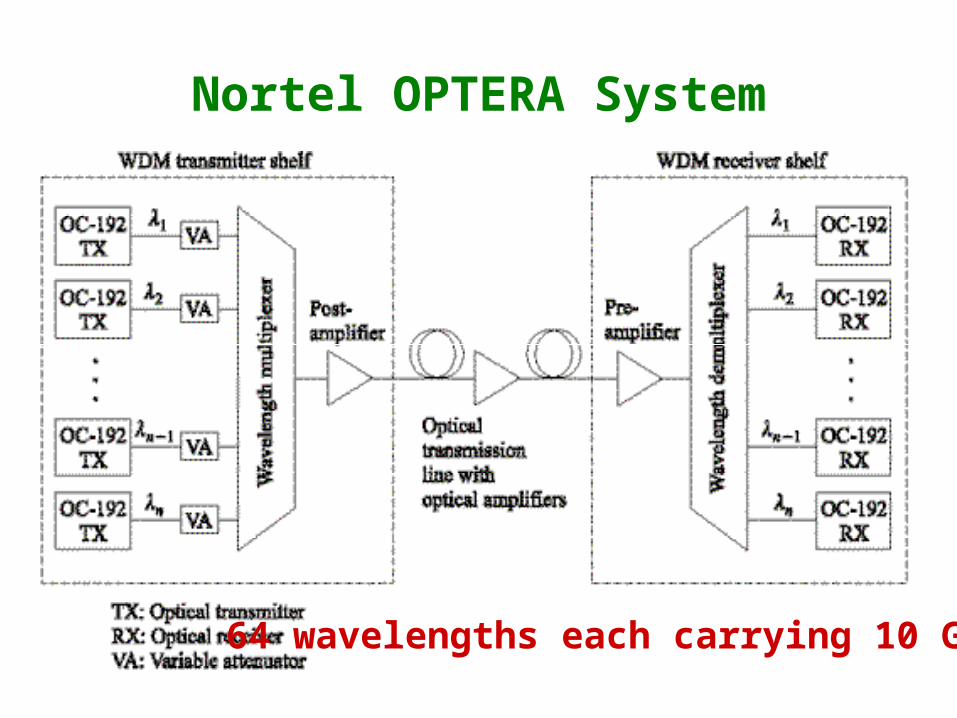
• Similar to Laser diodes but the emission is triggered by input optical signal
• Work in any wavelength (+)• Have high integration, compact and low power
consumption (+)• Gain fluctuation with signal bit rate (-)• Cross talk between different wavelengths (-)• Two types: Fabry-Perot or Traveling Wave Amp.
Semiconductor Optical Amplifiers

Generic optical amplifier
Continuous Wave(Constant)
Energy is transferred from the pump to signal

Solid State Amplifier Gain versus Power

Distributed Fiber Amplifiers• The active medium is created by lightly
doping silica fiber core by rare earth element Ex: Erbium (Er)
• Long fiber length (10-30 m)• Low coupling loss (+)• Transparent to signal format and bit rate• No cross talk• Broad output spectrum (1530 – 1560 nm)
Works only in specific Wavelengths

~1550 nm
980 nm
RadiationlessDecay
~1550 nm
Pump
Signal
Output
Optical Pumping to Higher Energy levels Rapid Relaxation to "metastable" State
Stimulated Emission and Amplification
N1
N2
N3
N1
N2
N3
N1
N2
N3
Amplification Process of EDFA

Fig. 11-4: Erbium energy-level diagram

EDFA configurations
Co-Directional Pumping
Counter Directional
Dual Pumping

Gain versus EDFA length
• There is an optimum length that gives the highest gain
• Negative gain if too long

Gain versus pump level
Gain decreases at large signal levels
Signal dependant gain
This increases with the pump power
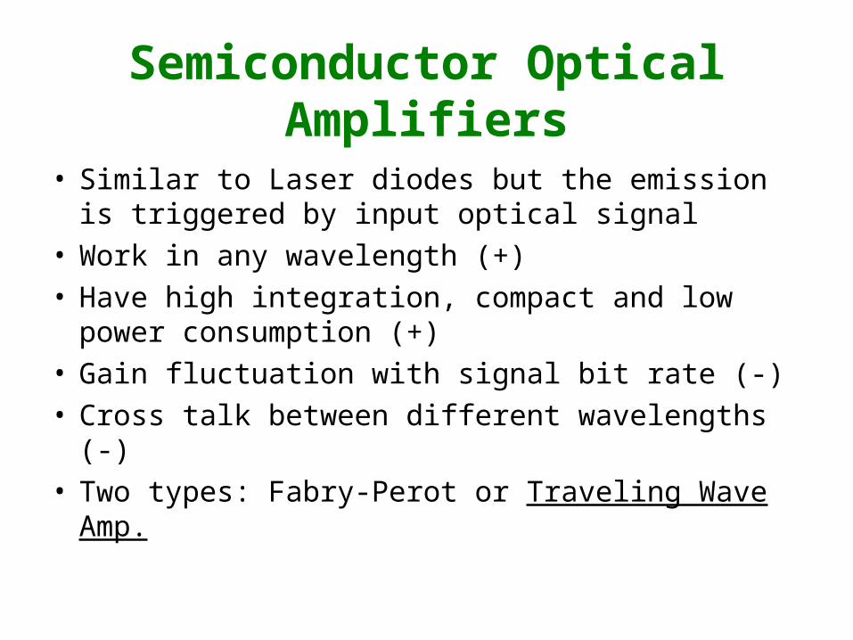
Amplified Spontaneous Emission (ASE) Noise

EDFA Noise Figure = (Input SNR)/(Output SNR)

SNR degradation due to amplification
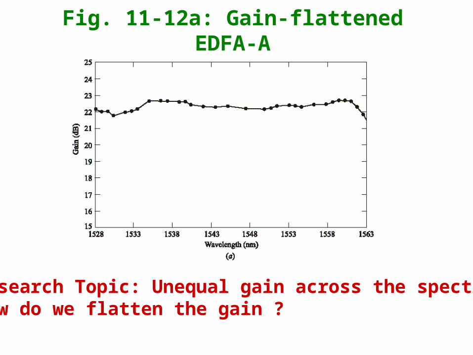
Fig. 11-12a: Gain-flattened EDFA-A
Research Topic: Unequal gain across the spectrum.How do we flatten the gain ?

Fig. 11-12b: Gain-flattened EDFA-B

Fig. 11-13: Passive gain control
Operating the DFA in the gain saturation region

Fig. 11-14: Wavelength conversion


![Analogy (Previous Years Question) [Adroit Vocab]](https://img.dokumen.tips/doc/110x75/577c854e1a28abe054bc90b0/analogy-previous-years-question-adroit-vocab.jpg)