Embed Size (px)
Citation preview

832019 Optic Profibus Manual
httpslidepdfcomreaderfulloptic-profibus-manual 178
ABB drives
Userrsquos manualMACRO adapter moduleFMAC-01
832019 Optic Profibus Manual
httpslidepdfcomreaderfulloptic-profibus-manual 278
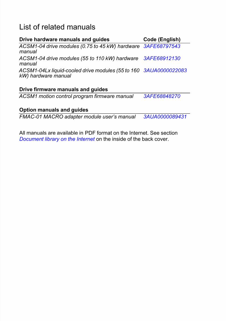
List of related manuals
All manuals are available in PDF format on the Internet See sectionDocument library on the Internet on the inside of the back cover
Drive hardware manuals and guides Code (English)
ACSM1-04 drive modules (075 to 45 kW) hardwaremanual
3AFE68797543
ACSM1-04 drive modules (55 to 110 kW) hardwaremanual
3AFE68912130
ACSM1-04Lx liquid-cooled drive modules (55 to 160 kW) hardware manual
3AUA0000022083
Drive firmware manuals and guides
ACSM1 motion control program firmware manual 3AFE68848270
Option manuals and guidesFMAC-01 MACRO adapter module userrsquos manual 3AUA0000089431
832019 Optic Profibus Manual
httpslidepdfcomreaderfulloptic-profibus-manual 378
Start-up
Userrsquos manual
MACRO adapter module
FMAC-01
3AUA0000089431 Rev AENEFFECTIVE 2010-12-03
copy 2010 ABB OyAll Rights Reserved
Safety
Table of contents
Mechanical installation
Electrical installation
832019 Optic Profibus Manual
httpslidepdfcomreaderfulloptic-profibus-manual 478
832019 Optic Profibus Manual
httpslidepdfcomreaderfulloptic-profibus-manual 578
Table of contents 5
Table of contents
List of related manuals 2
1 Safety
What this chapter contains 9
Use of warnings 10
Safety in installation 11
2 About the manual
What this chapter contains 13
Applicability 13
Compatibility 13
Target audience 13Purpose of the manual 14
Related documents 14
Before you start 14
Contents 15
Terms and abbreviations used in this manual 16General terms 16
MACRO terms 17
Abbreviations 19
3 Overview of the MACRO network and the FMAC-01
module
What this chapter contains 21
MACRO network 21
Topology of the MACRO ring 23
Logical arrangement of the MACRO network 23
FMAC-01 MACRO adapter module 25
Layout of the adapter module 26
4 Mechanical installation
What this chapter contains 27Delivery check 27
832019 Optic Profibus Manual
httpslidepdfcomreaderfulloptic-profibus-manual 678
6 Table of contents
Mounting the adapter module 28
5 Electrical installation
What this chapter contains 29
General cabling instructions 29Connecting the module to the MACRO network 30
6 Start-up
What this chapter contains 31
Drive configuration 32
FMAC-01 configuration parameters ndash group A (group 1) 32
FMAC-01 configuration parameters ndash group B (group 2) 43
FMAC-01 configuration parameters ndash group C (group 3) 45Control locations 47
Starting up the ACSM1 drive 47
Parameter setting examples ndash Fieldbus communication 49
Parameter setting examples ndash Drive control 50
Parameter setting examples ndash Resolver configuration 51
Parameter setting examples ndash Home position capture with
homing switch 52Parameter setting examples ndash Home position capture with
emulated zero pulse 53
Parameter setting examples ndash End limit inputs 55
Configuring the master system 56
Configuring Delta Tau Turbo PMAC 56
7 Communication profiles
What this chapter contains 59Communication profiles 59
MACRO Station profile 60
MACRO Station control and status flags 61
8 Communication protocol
What this chapter contains 63
MACRO protocol 63MACRO frame structure 63
Services 64
832019 Optic Profibus Manual
httpslidepdfcomreaderfulloptic-profibus-manual 778
Table of contents 7
Writing and reading drive parameters 64
Axis node MACRO 72-bit cyclic IO format 65
Fast digital output transfer in Control word 67
Home position position capture and overtravel limits 67
IO node MACRO 72-bit cyclic IO format 68Absolute power-on position 68
Flag capture position 68
ASCII transfer commands 69
Ring order set-up 70
Timing and synchronization 70
Acyclic and cyclic communication modes 71
MI-variables supported by FMAC-01 71
9 Diagnostics
What this chapter contains 73
LED indications 73
10 Technical data
What this chapter contains 75
FMAC-01 75MACRO link 76
Further information
Product and service inquiries 77
Product training 77
Providing feedback on ABB Drives manuals 77
Document library on the Internet 77
832019 Optic Profibus Manual
httpslidepdfcomreaderfulloptic-profibus-manual 878
8 Table of contents
832019 Optic Profibus Manual
httpslidepdfcomreaderfulloptic-profibus-manual 978
Safety 9
Safety
What this chapter contains
The chapter presents the warning symbols used in this manual andthe safety instructions which you must follow when installing afieldbus adapter module into a drive solar inverter or windconverter If ignored physical injury or death may follow or damage may occur to the equipment Read this chapter before you
start the installation
832019 Optic Profibus Manual
httpslidepdfcomreaderfulloptic-profibus-manual 1078
10 Safety
Use of warnings
Warnings caution you about conditions which can result in seriousinjury or death andor damage to the equipment and advise on howto avoid the danger The following warning symbols are used in
this manual
Electricity warning warns of hazards from electricity
which can cause physical injury andor damage to the
equipment
General warning warns about conditions other than
those caused by electricity which can result in physical
injury andor damage to the equipment
832019 Optic Profibus Manual
httpslidepdfcomreaderfulloptic-profibus-manual 1178
Safety 11
Safety in installation
These warnings are intended for all who install a fieldbus adapter module into a drive solar inverter or wind converter
WARNING Ignoring the following instructions can cause
physical injury or death or damage to the equipment
bull Only qualified electricians are allowed to install and maintain
the drive solar inverter or wind converter
bull Disconnect the drive solar inverter or wind converter into
which the module will be installed from all possible power
sources After disconnecting always wait for 5 minutes to let
the intermediate circuit capacitors discharge before you
proceed
bull Always ensure by measuring with a multimeter (impedance at
least 1 Mohm) that
bull there is no voltage between the input power terminals of
the drive solar inverter or wind converter and the ground
bull there is no voltage between the output power terminals of
the drive solar inverter or wind converter and the ground
bull Do not work on the control cables when power is applied to the
external control circuits of the drive solar inverter or wind
converter Externally supplied control circuits may carry
dangerous voltage
832019 Optic Profibus Manual
httpslidepdfcomreaderfulloptic-profibus-manual 1278
12 Safety
832019 Optic Profibus Manual
httpslidepdfcomreaderfulloptic-profibus-manual 1378
About the manual 13
About the manual
What this chapter contains
This chapter introduces this manual
Applicability
This manual applies to the FMAC-01 MACRO adapter module SWversion 0009 and later
Compatibility
The FMAC-01 MACRO adapter module is compatible with the ABBACSM1-04 and ACSM1-04Lx drives with the Motion controlprogram Note that FMAC-01 is not compatible with the Speed andtorque control program
FMAC-01 is a microMACRO station implementation and it iscompatible with all MACRO masters that support microMACROstations
Target audience
The reader is expected to have a basic knowledge of the MACROnetwork electrical fundamentals electrical wiring practices andhow to operate the drive
832019 Optic Profibus Manual
httpslidepdfcomreaderfulloptic-profibus-manual 1478
14 About the manual
Purpose of the manual
The manual provides information on installing commissioning andusing the FMAC-01 MACRO adapter module
Related documents
Related manuals are listed on the inside front cover
Before you start
It is assumed that the drive is installed and ready to operate beforestarting the installation of the adapter module
In addition to conventional installation tools have the drivemanuals available during the installation as they contain importantinformation not included in this manual The drive manuals arereferred to at various points of this document
832019 Optic Profibus Manual
httpslidepdfcomreaderfulloptic-profibus-manual 1578
832019 Optic Profibus Manual
httpslidepdfcomreaderfulloptic-profibus-manual 1678
16 About the manual
Terms and abbreviations used in this manual
General terms
Term Explanation
Communication module Communication module is a name for a device
(eg a fieldbus adapter) through which the drive
is connected to an external communication
network (eg a fieldbus) The communication
with the module is activated with a drive
parameter
Command word See Control word
Control word A 16-bit word from a master to a slavecontaining commands for the addressed drive(usually called the Command word)
FMAC-01 MACROadapter module
The FMAC-01 MACRO adapter module is oneof the optional fieldbus adapter modulesavailable for ABB drives FMAC-01 is a devicethrough which an ABB drive is connected to aMACRO network
Parameter An operating instruction for the driveParameters can be read and programmed withthe drive control panel drive PC tools or through the adapter module
Profile Adaptation of the protocol for certain applicationfield for example drives
Status word A 16-bit word from a slave to a master containing status information
832019 Optic Profibus Manual
httpslidepdfcomreaderfulloptic-profibus-manual 1778
About the manual 17
MACRO terms
Term Explanation
Amplifier In this manual lsquoamplifierrsquo denotes lsquodriversquo
Axis node Slave node type used for sending axis controlcommands to and receiving feedback from thedrive Axis node communication consists of a72-bit data frame that is transferred cyclicallybetween a master node and a slave node
Broadcast The act of sending a data packet to multipleMACRO stations
Control flag A 24-bit control word containing MACRO-
specific control commands for the addressedslave station
Data packet The set of data that is transmitted or receivedby a node during each ring communicationscycle
IO node Slave node type used for cyclic transfer of additional process data between the master andthe drive The 72-bit data frame can be used totransfer parameter-mapped data to and fromthe drive such as control and status of thedrives digital and analog IO
Master An entity on the ring that sends command datapackets and receives feedback data packets
Master node A logical unit and set of registers on the ringthat can send command data packets to acorresponding slave node and receive feedbackdata packets from the corresponding slave
node
Master number A value from 0hellip15 that is assigned to eachmaster node on a ring The master number isused with the slave number to associate datapackets with nodes
Master station A station on the ring containing one or moremaster nodes
832019 Optic Profibus Manual
httpslidepdfcomreaderfulloptic-profibus-manual 1878
18 About the manual
MI-variable A pre-defined data object similar to eg driveparameters that are used by the master node tosend and receive eg configuration data to and
from a slave nodeNode A logical unit on the ring A node device sends
and receives a data packet once each
ring communications cycle All nodes possessboth a master number (0hellip15) and a slave
number (0hellip15) whether the node is a master node or a slave node For communications
there must be corresponding master and slavenodes
Ring MACRO ring network A system of devices thatare interconnected by a fiber optic or twistedpair copper cable that uses MACRO protocols
Slave An entity on the ring that receives commanddata packets and sends feedback data packets
Slave node A logical unit and set of registers on the ringthat can receive command data packets from a
corresponding master node and transmitfeedback data packets back to the
corresponding master node
Slave number A value from 0hellip15 associated with each nodeThere are 16 slave nodes which may beaddressed per master in a ring The slavenumber is used with the master number toassociate data packets with nodes
Slave station A station on the ring containing one or moreslave nodes
Station A physical unit on the ring with a ring receivingcircuit ring transmission circuit and the circuitryfor one or more nodes There may be more thanone station in a single hardware device
Status flag A 24-bit status word from a slave station to amaster containing MACRO-specific statusinformation
Term Explanation
832019 Optic Profibus Manual
httpslidepdfcomreaderfulloptic-profibus-manual 1978
About the manual 19
Abbreviations
Synchronizing master The single master station on the ring that startsa ring communications cycle based on its owninternal timing circuitry Any other master
stations on the ring must await receipt of thebaton signal from the upstream master beforestarting its communications
Abbreviation Explanation
EMC Electromagnetic compatibility
FBA Fieldbus adapter
LSB Least significant bit
MSB Most significant bit
Term Explanation
832019 Optic Profibus Manual
httpslidepdfcomreaderfulloptic-profibus-manual 2078
20 About the manual
832019 Optic Profibus Manual
httpslidepdfcomreaderfulloptic-profibus-manual 2178
Overview of the MACRO network and the FMAC-01 module 21
Overview of the MACROnetwork and the FMAC-01module
What this chapter contains
This chapter contains a short description of the MACRO network
and the FMAC-01 MACRO adapter module
MACRO network
MACRO stands for ldquoMotion And Control Ring Opticalrdquo MACRO isa non-proprietary digital high-speed bus interface developed byDelta Tau Data systems for connecting multi-axis motioncontrollers amplifiers and distributed IO on a fiber optic or twistedpair copper ring
One physical master or slave station in a MACRO network maycontain multiple logical master or slave nodes Altogether MACROsupports up to 16 master stations Each master station supports upto 16 slave nodes so it is possible to build a network with 256slave nodes The maximum distance between nodes is 3000 musing fiber optic cables Data rate is configurable the maximumbeing 125 Mbits
MACRO lends itself to large multi-axis applications where the
amplifiers and IO are spread out as well as smaller applicationswhere wiring simplicity and noise immunity are preferred
832019 Optic Profibus Manual
httpslidepdfcomreaderfulloptic-profibus-manual 2278
22 Overview of the MACRO network and the FMAC-01 module
The advantages of MACRO are multi-master capability support for high transmission speed and noise immunity on optical fiber
MACRO has two types of application layers called TYPE 0 andTYPE 1 protocols The difference between these two protocols isthat TYPE 0 strives to use more nodes but less data while TYPE1 strives to use more data per node but with less nodesbull TYPE 0 supports 16 nodes of data per master with 48 bits of
data per node
bull TYPE 1 supports 14 nodes of data per master with 72 bits of
data per node
Further information is available at wwwmacroorg andwwwdeltataucom
832019 Optic Profibus Manual
httpslidepdfcomreaderfulloptic-profibus-manual 2378
Overview of the MACRO network and the FMAC-01 module 23
Topology of the MACRO ring
The figure below illustrates a MACRO ring with two master stationsand six slave stations The order of the stations on the ring is notsignificant
Logical arrangement of the MACRO network
Every node on a MACRO ring has an 8-bit node address Thenode address consists of a 4-bit master number (0hellip15) and a 4-bitslave number (0hellip15) The corresponding master and slave nodeshave the same node address There may be only one activemaster node and one active slave node on the ring with any givennode address As there are 256 possible node addresses there
can be up to 256 active master nodes and 256 active slave nodeson the ring
Slave station 1 controlled by
master station1
Slave station 2 controlled by
master station 1
Slave station 3 controlled by
master station 1Slave station 4
controlled bymaster station 2
Slave station 5controlled by
master station 2
Slave station 6controlled by
master station 2
Master station 2
Master station 1
832019 Optic Profibus Manual
httpslidepdfcomreaderfulloptic-profibus-manual 2478
24 Overview of the MACRO network and the FMAC-01 module
Although it is customary to configure the network so that all thenodes in one station use the same master number it is not arequirement of the MACRO standard
The figure below illustrates the logical principle of the MACROnetwork In this example there is one master station with threeactive master nodes and two slave stations with three active slavenodes in the network One slave station has two active slavenodes while the other slave station has one active slave node Themaster and slave nodes having the corresponding node addressescommunicate with each other through the MACRO network
Master station
Master node0501
Master node
Master node
0502
0504
Slave node0501
Slave node0502
Slave station
Slave node0504
Slave station
832019 Optic Profibus Manual
httpslidepdfcomreaderfulloptic-profibus-manual 2578
Overview of the MACRO network and the FMAC-01 module 25
FMAC-01 MACRO adapter module
The FMAC-01 MACRO adapter module is an optional device for ABB drives which enables the connection of the drive to a MACROnetwork
Through the adapter module it is possible to
bull give control commands to the drive (Start Stop Run enable
etc)
bull feed a motor speed or torque reference to the drive
bull give a process actual value or a process reference to the PID
controller of the drive
bull read status information and actual values from the drivebull reset a drive fault
The FMAC-01 MACRO adapter module implements the TYPE 1MACRO protocol as a microMACRO station This means support for
bull Delta Tau-specific application layer protocols such as
MI-variables
bull MACRO services such as Home position position capture
and overtravel limits
The MACRO commands and services supported by the adapter module are discussed in chapter Communication protocol Refer tothe user documentation of the drive as to which commands aresupported by the drive
The adapter module is mounted into an option slot on the motor control board of the drive See the drive manuals for moduleplacement options
832019 Optic Profibus Manual
httpslidepdfcomreaderfulloptic-profibus-manual 2678
26 Overview of the MACRO network and the FMAC-01 module
Layout of the adapter module
DiagnosticLEDs
(see chapter Diagnostics)
Mountingscrew
Side view
Top view
Transmitter optical output(see chapter Electrical installation)
Receiver optical input(see chapter Electrical
installation)
832019 Optic Profibus Manual
httpslidepdfcomreaderfulloptic-profibus-manual 2778
Mechanical installation 27
Mechanical installation
What this chapter contains
This chapter contains a delivery checklist and instructions onmounting the adapter module
WARNING Follow the safety instructions given in thismanual and the drive documentation
Delivery check
The option package for the adapter module contains
bull MACRO adapter module type FMAC-01bull this manual
832019 Optic Profibus Manual
httpslidepdfcomreaderfulloptic-profibus-manual 2878
28 Mechanical installation
Mounting the adapter module
The adapter module is to be inserted into its specific position in thedrive The module is held in place with plastic pins and one screwThe screw also provides the electrical connection between the
module and drive frame for cable shield terminationWhen the module is installed the signal and power connection tothe drive is made through a 20-pin connector (All drives do not useall the available signals so the connector on the drive may havefewer pins)
Mounting procedure
1 Insert the module carefully into its position on the drive
2 Fasten the screw
Note It is essential to install the screw properly to fulfill the EMCrequirements and to ensure the proper operation of the module
For more information on mounting see the drive manuals
832019 Optic Profibus Manual
httpslidepdfcomreaderfulloptic-profibus-manual 2978
Electrical installation 29
Electrical installation
What this chapter contains
This chapter contains general cabling instructions and instructionson connecting the adapter module to the MACRO network
WARNING Before installation switch off the drive power supply Wait five minutes to ensure that the capacitor bank
of the drive is discharged Switch off all dangerous
voltages connected from external control circuits to the inputs and
outputs of the drive
General cabling instructionsbull Follow the general cabling rules for 100BaseFX fiber optic
cables When laying the cables keep in mind the basic
limitations of fiber optic cables such as the minimum bending
radius and abrasion resistance
bull Use bushings at cable entries
832019 Optic Profibus Manual
httpslidepdfcomreaderfulloptic-profibus-manual 3078
30 Electrical installation
Connecting the module to the MACRO network
1 Connect the network cables to the two SC connectors (X1 and
X2) on the adapter module
2 Connect the cable from the output of the previous device onthe ring to the right port (IN X2) of the adapter module
3 Connect the cable from the left port (OUT X1) of the adapter
module to the input of the next device on the ring
The figure below illustrates the cable connections
Adapter module
Master
station
IN
OUT
IN
X1
Another slave device
INOUT
OUT
X2
Adapter module
IN
X1
OUT
X2
832019 Optic Profibus Manual
httpslidepdfcomreaderfulloptic-profibus-manual 3178
Start-up 31
Start-up
What this chapter contains
This chapter contains
bull information on configuring the drive for operation with the
adapter module
bull instructions on starting up the adapter module with the drive
bull instructions on configuring the master system to communicatewith the adapter module
WARNING Follow the safety instructions given in this
manual and the drive documentation
832019 Optic Profibus Manual
httpslidepdfcomreaderfulloptic-profibus-manual 3278
832019 Optic Profibus Manual
httpslidepdfcomreaderfulloptic-profibus-manual 3378
Start-up 33
05 AXIS NODE
ADDRESS(MI996)
FBA PAR5 0 1 4 5 8 912
13
0
06 AXIS NODEENABLE (MI996)
FBA PAR6 0 = DISABLED
1 = ENABLED
0
07 IO NODEADDRESS(MI996)
FBA PAR7 2 3 6 7 10 11 2
08 IO NODE
ENABLE (MI996)
FBA PAR8 0 = DISABLED
1 = ENABLED
0
09 STATION ORDERNUMBER (MI11)
FBA PAR9 0hellip254 0
10 STATIONFIRMWAREVERSION (MI0)
FBA PAR10 0hellip9999 (BCD) 0
11 STATION ID USERCONFIGURATIONWORD HI (MI2)
FBA PAR11 0x00hellip0xFF 0
12 STATION ID USERCONFIGURATIONWORD LO (MI2)
FBA PAR12 0x0000hellip0xFFFF 0
Parno
Parameter name Parameter name in thedrive
Alternativesettings
Defaultsetting
832019 Optic Profibus Manual
httpslidepdfcomreaderfulloptic-profibus-manual 3478
34 Start-up
13 STATION STATUS
(MI4)
FBA PAR13 0hellip63
Decimalenumerated bitfield
Bit 5 SYNCPACKET FAULT
Bit 4 RINGACTIVE
Bit 3 PERMANENT
RING FAULTBit 2 STATIONFAULTSHUTDOWN
Bit 1 RINGBREAK FAULT
Bit 0 CONFIGURATIONFAULT
0
14 MACRO RINGCHECK PERIOD(MI8)
FBA PAR14 0hellip255 (servocycles)
200
15 MACRO RINGERRORSHUTDOWNCOUNT (MI9)
FBA PAR15 0hellip65535 20
16 MACRO SYNCPACKETSHUTDOWNCOUNT (MI10)
FBA PAR16 0hellip65535 180
17 RING ERRORCOUNTER HI(MI5)
FBA PAR17 0x00hellip0xFF 0
18 RING ERRORCOUNTER LO
(MI5)
FBA PAR18 0x0000hellip0xFFFF 0
Parno
Parameter name Parameter name in thedrive
Alternativesettings
Defaultsetting
832019 Optic Profibus Manual
httpslidepdfcomreaderfulloptic-profibus-manual 3578
Start-up 35
19 CLOCK
CONTROL HI(MI990)
FBA PAR19 0x0000hellip0xFFFF 5000
20 CLOCKCONTROL LO(MI990)
FBA PAR20 0x0000hellip0xFFFF 1092
21 RAWREFERENCESCALE
FBA PAR21 0hellip65535 8
22 POSITIONFEEDBACKFORMAT (MI20)
FBA PAR22 0hellip7 0
23hellip26
- FBA PAR23hellipFBA PAR26
- 0
27 PARAMETERREFRESH
FBA PARREFRESH
0 = DONE
1 = REFRESH
0
28 PARAMETERTABLE REVISION
PAR TABLEVER (Read-only)
0
29 DRIVE TYPECODE
DRIVE TYPECODE
(Read-only) 0
30 MAPPING FILEREVISION
MAPPINGFILE VER
(Read-only) 0
31 FBA COMMUNI-CATION STATUS
D2FBACOMM STA
(Read-only) 0
32 FBA COMMONPROGRAMREVISION
FBA COMMSW VER
(Read-only) 0
33 FBAAPPLICATIONPROGRAMREVISION
FBA APPLSW VER
(Read-only) 0
Not used by the adapter module
Parno
Parameter name Parameter name in thedrive
Alternativesettings
Defaultsetting
832019 Optic Profibus Manual
httpslidepdfcomreaderfulloptic-profibus-manual 3678
36 Start-up
01 FBA TYPE
This parameter displays the fieldbus adapter type as detected bythe drive The value cannot be adjusted by the user
If the value of this parameter is zero communication between anymodule and the drive has never been established before
02 PROFILE
This parameter selects the communication profile used by theadapter module The following profile is available
bull 0 = MACRO Station
For more information on the profile see chapter Communication
profiles
03 MASTER ADDRESS (SW2) (MI996 and MI3)
This parameter sets the master node address which the adapter module will listen to
04 SW1 (MI3)
This parameter is an alternative way to set up the axis node andIO node (parameters 05 06 07 and 08)
This parameter takes precedence over parameters 05 06 07 and08 for all values except when set to 14 When this parameter is setto 14 parameters 05 06 07 and 08 will be used
The table below shows the settings available
SW1 value MI996 value Node enabled
0 0x0F1FE20 01 0x0F1FE31 1
2 0x0F3FE20 0 and 2
3 0x0F3FE31 1 and 3
4 0x0F1FE64 4
5 0x0F1FE75 5
6 0x0F3FE64 4 and 67 0x0F3FE75 5 and 7
832019 Optic Profibus Manual
httpslidepdfcomreaderfulloptic-profibus-manual 3778
Start-up 37
05 AXIS NODE ADDRESS (MI996)
There is one axis node in FMAC-01 whose address can beselected as 0 1 4 5 8 9 12 or 13
Note This parameter is only active when SW1 (parameter 04) isset to 14
06 AXIS NODE ENABLE (MI996)
bull 0 = Axis node communication is disabled
bull 1 = Axis node communication is enabled
Note This parameter is only active when SW1 (parameter 04) isset to 14
07 IO NODE ADDRESS (MI996)
There is one IO node in FMAC-01 whose address can beselected as 2 3 6 7 10 or 11 IO node communication is updatedless frequently than axis node communication
Note This parameter is only active when SW1 (parameter 04) isset to 14
8 0x0F1FEA8 8
9 0x0F1FEB9 9
10 0x0F3FEA8 8 and 1011 0x0F3FEB9 9 and 11
12 0x0F1FE2C 12
13 0x0F1FE3D 13
14 0x0F0FE10 None (Settings from par 05 06 07and 08)
15 0x0F1FE1B 11 (Set MI-variables to the factory
default)The master node address in MI996 is not affected
SW1 value MI996 value Node enabled
832019 Optic Profibus Manual
httpslidepdfcomreaderfulloptic-profibus-manual 3878
38 Start-up
08 IO NODE ENABLE (MI996)
bull 0 = IO node communication is disabled
bull 1 = IO node communication is enabled
Note This parameter is only active when SW1 (parameter 04) isset to 14
09 STATION ORDER NUMBER (MI11)
This parameter allows a MACRO controller to set up the ring order using ASCII communication When the station order number is setto 0 the MACRO controller will identify the station as ldquounorderedrdquoand assign a station order number for it as well as set up the axis
and IO node settings (parameters 05 06 07 and 08)Note This parameter is only active when SW1 (parameter 04) isset to 14
10 STATION FIRMWARE VERSION (MI0)
This parameter shows the MACRO station firmware version usedin the adapter module Note that it is not the same as the FMAC-01firmware version
11 STATION ID USER CONFIGURATION WORD HI (MI2)
Most significant 8 bits (bits 23hellip16) of MI2 The parameter can beused to store user configuration data such as a station ID
12 STATION ID USER CONFIGURATION WORD LO (MI2)
Least significant 16 bits (bits 15hellip0) of MI2 See parameter 11
832019 Optic Profibus Manual
httpslidepdfcomreaderfulloptic-profibus-manual 3978
Start-up 39
13 STATION STATUS (MI4)
Each bit of this parameter reports the presence or absence of aparticular faultstatus
bull If the bit is 0 the condition is false
bull If the bit is 1 the condition is true
Example If the value of this parameter is 5 it means that bits 0and 2 are set that is a configuration fault and station fault haveoccurred
14 MACRO RING CHECK PERIOD (MI8)This parameter sets the number of servo cycles within which astation must receive at least the sync packet count of sync packets(par 16 MI10) and detect fewer ring communication errors thanthe ring error shutdown count (par 15 MI9) to conclude that thering is operating correctly
15 MACRO RING ERROR SHUTDOWN COUNT (MI9)
This parameter sets the number of MACRO communication errorsdetected that will cause a station fault (station shutdown)
16 MACRO SYNC PACKET SHUTDOWN COUNT (MI10)
This parameter sets the number of MACRO ring sync packets thatmust be received during a MACRO ring check period (par 14 MI8)to conclude that the ring is operating correctly
Bit Description
5 SYNC PACKET FAULT
4 RING ACTIVE
3 PERMANENT RING FAULT
2 STATION FAULT (station shutdown)
1 RING BREAK FAULT
0 CONFIGURATION FAULT
832019 Optic Profibus Manual
httpslidepdfcomreaderfulloptic-profibus-manual 4078
40 Start-up
17 RING ERROR COUNTER HI (MI5)
Most significant 8 bits (bits 23hellip16) of MI5 The counter shows thenumber of ring communications errors detected since the power-up or reset
18 RING ERROR COUNTER LO (MI5)
Least significant 16 bits (bits 15hellip0) of MI5 See parameter 17
19 CLOCK CONTROL HI (MI990)
Most significant 16 bits (bits 31hellip16) of MI990
MI990 combines MI992 MI993 and MI994 and contains
information about the phase clock servo encoder clock and clockdivisors
20 CLOCK CONTROL LO (MI990)
Least significant 16 bits (bits 15hellip0) of MI990 See parameter 19
21 RAW REFERENCE SCALE
This parameter determines the reference scaling when driveparameter 5004 FBA REF1 MODESEL is set to lsquoRaw datarsquo
The reference received is multiplied by the value of this parameter
Example If the parameter is set to 8 and the incoming reference is1000 the reference passed to the drive will be 8000
832019 Optic Profibus Manual
httpslidepdfcomreaderfulloptic-profibus-manual 4178
Start-up 41
22 POSITION FEEDBACK FORMAT (MI20)
The three least significant bits of this parameter determine theposition feedback format for the cyclic and non-cyclic position data
23hellip26
These parameters are not used by the adapter module
27 PARAMETER REFRESH
This parameter validates any changed adapter moduleconfiguration parameter settings After refreshing the value revertsautomatically to 0 = DONE
Note This parameter cannot be changed while the drive isrunning
28 PARAMETER TABLE REVISION
This parameter displays the parameter table revision of the
fieldbus adapter module mapping file stored in the memory of thedrive In format xyz where
bull x = major revision number
bull y = minor revision number
bull x = correction number
29 DRIVE TYPE CODE
This parameter displays the drive type code of the fieldbus adapter module mapping file stored in the memory of the drive
Bit Value Description
2 0 Non-cyclic Absolute Position Data not shifted
1 Non-cyclic Absolute Position Data shifted by 5 bits tothe right
1 0 Non-cyclic Absolute Position Data not shifted
1 Non-cyclic Position Capture Data shifted by 5 bits to theright
0 0 Cyclic Servo Position Data shifted by 5 bits to the left1 Cyclic Servo Position Data not shifted
832019 Optic Profibus Manual
httpslidepdfcomreaderfulloptic-profibus-manual 4278
42 Start-up
30 MAPPING FILE REVISION
This parameter displays the fieldbus adapter module mapping filerevision stored in the memory of the drive in decimal formatExample 0x107 = revision 107
31 FBA COMMUNICATION STATUS
This parameter displays the status of the fieldbus adapter modulecommunication
32 FBA COMMON PROGRAM REVISION
This parameter displays the common program revision of theadapter module in format axyz where
bull a = major revision number
bull xy = minor revision numbers
bull z = correction letter
Example 190A = revision 190A
33 FBA APPLICATION PROGRAM REVISION
This parameter displays the application program revision of theadapter module in format axyz where
bull a = major revision number
bull xy = minor revision numbers
bull z = correction letter
Example 190A = revision 190A
832019 Optic Profibus Manual
httpslidepdfcomreaderfulloptic-profibus-manual 4378
Start-up 43
FMAC-01 configuration parameters ndash group B
(group 2)
Note The actual parameter group number depends on the drivetype Group B (group 2) equals to parameter group 53 in ACSM1
Parno
Parameter name
Parameter namein drive
Alternative settings Defaultsetting
01 DATA OUT 1(master todrive)
FBA DATA OUT1 0hellip9999
Format xxyy where
xx = parameter group
and
yy = parameter index
0
02 DATA OUT 2 FBA DATA OUT2 See DATA OUT 1above
0
03 DATA OUT 3 FBA DATA OUT3 See DATA OUT 1above
0
04 DATA OUT 4 FBA DATA OUT4 See DATA OUT 1above
0
05 DATA OUT 5 FBA DATA OUT5 - 0
06 DATA OUT 6 FBA DATA OUT6 - 007 DATA OUT 7 FBA DATA OUT7 - 0
08 DATA OUT 8 FBA DATA OUT8 - 0
09 DATA OUT 9 FBA DATA OUT9 - 0
10 DATA OUT 10 FBA DATAOUT10
- 0
11 DATA OUT 11 FBA DATA
OUT11
- 0
12 DATA OUT 12 FBA DATAOUT12
- 0
Not used by the adapter module
832019 Optic Profibus Manual
httpslidepdfcomreaderfulloptic-profibus-manual 4478
44 Start-up
01 DATA OUT 1
This parameter represents data word 1 received by the drive over the MACRO network in IO node communication The content isdefined by a decimal number in the range of 0 to 9999 as follows
The parameter area is allocated as follows
Parameter number with format xxyy where xx is the parameter group number (1 to 99) and yy is the parameter number indexwithin that group (01 to 99)
Note One DATA OUT parameter can assign only 16 bits of data tofieldbus communication When a 32-bit drive parameter isassigned to fieldbus communication the assigned parameter reserves two consecutive parameters from group B
See also section IO node MACRO 72-bit cyclic IO format on page68
02 DATA OUT 2 to 04 DATA OUT 4
See parameter 01 above
05 DATA OUT 5 to 12 DATA OUT 12
These parameters are not used by the adapter module
0 not used
101hellip9999 parameter area of the drive
832019 Optic Profibus Manual
httpslidepdfcomreaderfulloptic-profibus-manual 4578
Start-up 45
FMAC-01 configuration parameters ndash group C
(group 3)
Note The actual parameter group number depends on the drivetype Group C (group 3) equals to parameter group 52 in ACSM1
Parno
Parameter name
Parameter namein drive
Alternative settings Defaultsetting
01 DATA IN 1(drive tomaster)
FBA DATA IN1 0hellip9999
Format xxyy where
xx = parameter group
and
yy = parameter index
0
02 DATA IN 2 FBA DATA IN2 See DATA IN 1 above 0
03 DATA IN 3 FBA DATA IN3 See DATA IN 1 above 0
04 DATA IN 4 FBA DATA IN4 See DATA IN 1 above 0
05 DATA IN 5 FBA DATA IN5 - 0
06 DATA IN 6 FBA DATA IN6 - 0
07 DATA IN 7 FBA DATA IN7 - 0
08 DATA IN 8 FBA DATA IN8 - 009 DATA IN 9 FBA DATA IN9 - 0
10 DATA IN 10 FBA DATA IN10 - 0
11 DATA IN 11 FBA DATA IN11 - 0
12 DATA IN 12 FBA DATA IN12 - 0
Not used by the adapter module
832019 Optic Profibus Manual
httpslidepdfcomreaderfulloptic-profibus-manual 4678
46 Start-up
01 DATA IN 1
This parameter represents data word 1 sent by the drive over theMACRO network in IO node communication The content isdefined by a decimal number in the range of 0 to 9999 as follows
The parameter area is allocated as follows
Parameter number with format xxyy where xx is the parameter group number (1 to 99) and yy is the parameter number indexwithin that group (01 to 99)
Note One DATA IN parameter can assign only 16 bits of data tofieldbus communication When a 32-bit drive parameter isassigned to fieldbus communication the assigned parameter reserves two consecutive parameters from group C
See also section IO node MACRO 72-bit cyclic IO format on page68
02 DATA IN 2 to 04 DATA IN 4
See parameter 01 above
05 DATA IN 5 to 12 DATA IN 12
These parameters are not used by the adapter module
0 not used
101hellip9999 parameter area of the drive
832019 Optic Profibus Manual
httpslidepdfcomreaderfulloptic-profibus-manual 4778
Start-up 47
Control locations
ABB drives can receive control information from multiple sourcesincluding digital inputs analog inputs the drive control panel and acommunication module (for example the adapter module) ABB
drives allow the user to separately determine the source for eachtype of control information (Start Stop Direction Reference FaultReset etc)
In order to give the fieldbus master station the most completecontrol over the drive the communication module must beselected as the source for this information The parameter settingexamples below contain the drive control parameters needed inthe examples For a complete parameter list see the driveFirmware manual
Starting up the ACSM1 drive
1 Power up the drive
2 Enable the communication between the adapter module and
the drive by setting parameter 5001 FBA ENABLE to
lsquoENABLErsquo
3 Select how the drive reacts to a fieldbus communication break
with parameter 5002 COMM LOSS FUNC In motion control
applications it is recommended to select setting lsquoFaultrsquo for this
parameter Note that this function monitors both
communication between the fieldbus master and adapter
module and communication between the adapter module and
drive
4 Define the time between communication break detection andthe selected action with parameter 5003 COMM LOSS T OUT
Note that adapter module will stop the drive in case of a
MACRO ring break regardless of the action selected with
parameter 5002
832019 Optic Profibus Manual
httpslidepdfcomreaderfulloptic-profibus-manual 4878
48 Start-up
5 Select MACRO-specific values for parameters 5004hellip5011
These parameters define the data transferred in axis node
communication See the parameter setting examples below
6 Set the FMAC-01 configuration parameters in parameter group
51 At the minimum set the required node address for themaster node with parameter 5103 and the node addresses for
the axis and IO nodes with parameter 5104
7 Define the IO node communication data transferred to and
from the drive in parameter groups 52 and 53 Note that IO
node communication allows only 72 bits of data Thus it is
possible to define variables only to parameters 1hellip4 in groups
52 and 53
8 Validate the settings made in parameter groups 51 52 and 53
by setting parameter 5127 FBA PAR REFRESH to
lsquoREFRESHrsquo
9 Enable the fieldbus communication synchronization in the
drive by setting parameter 5709 KERNEL SYNC MODE to
lsquoFBSyncrsquo
10 Set the relevant drive control parameters encoder
configuration parameters and MACRO-specific position control
parameters See the parameter setting examples below
832019 Optic Profibus Manual
httpslidepdfcomreaderfulloptic-profibus-manual 4978
Start-up 49
Parameter setting examples ndash Fieldbus
communication
Drive parameter Setting Description
5001 FBA ENABLE 1 = Enable Enables the communicationbetween the drive and theadapter module
5002 COMM LOSSFUNC
1 = FAULT Enables fieldbuscommunication faultmonitoring and selects faultas the action upon a fieldbuscommunication break
5003 COMM LOS TOUT
30 s Defines that a communicationfault is activated 3 secondsafter the fieldbuscommunication break hasbeen detected
5004 FBA REF1MODESEL
0 = Raw data Sets the fieldbus REF1ACT1mode to lsquoRaw datarsquo
5005 FBA REF2MODESEL
3 = Position Sets the fieldbus REF2ACT2mode to lsquoPositionrsquo
5006 FBA ACT1 TRSRC
P0403(PROBE1 POSMEAS)
Sets par 0403 as the sourceof the captured value
(To capture on probe 2 setpar 0404 PROBE2 POSMEAS as the source)
5007 FBA ACT2 TRSRC
P0112(POS ACT)
Sets par 0112 as the sourceof position feedback to theadapter module
5011 FBA SW B15SRC
P061108(POS CORRSTATUS bit 8LATCH1 DONE)
Sets par 0611 bit 8 LATCH1DONE as the source of FBAMAIN SW bit 31
(This setting causes thecapturing to use probe 1 If using probe 2 set par 0611bit 9 LATCH2 DONE as thesource)
5103 SW2 0 Selects the master nodeaddress
832019 Optic Profibus Manual
httpslidepdfcomreaderfulloptic-profibus-manual 5078
50 Start-up
Parameter setting examples ndash Drive control
5104 SW1 2 Enables nodes 0 and 2
5121 RAWREFERENCE SCALE
8 Defines that the torquereference sent by the master
is multiplied by 8 beforepassed to the drive
5122 CYCLICPOSITIONFEEDBACK FORMAT
1 Defines that there will be noshifting of the positionfeedback value
5127 FBA PARREFRESH
1 = REFRESH Validates the FMAC-01configuration parameters
Drive parameter Setting Description
1001 EXT1 STARTFUNC
3 = FBA Allows the drive to be startedby the adapter module
2201 SPEED FB SEL Enc1 speed Selects the actual speedmeasured by encoder 1 asthe speed feedback
3201 TORQ REF1SEL
3 = FBA REF1 Selects the fieldbus REF1input as TORQUE REF1
3401 EXT1EXT2 SEL CFalse Selects EXT1 as the controllocation
3403 EXT1 CTRLMODE1
2 = Torque Selects the Torque controlmode for EXT1
5709 KERNEL SYNC
MODE
2 = FBSync Keeps the drive in sync with
the servo clock
6001 POS ACT SEL 0 = ENC1 Selects ENC1 as the sourcefor the position feedback
6009 POSRESOLUTION
18 bits Sets the number of bits for theresolution of one revolution
Drive parameter Setting Description
832019 Optic Profibus Manual
httpslidepdfcomreaderfulloptic-profibus-manual 5178
Start-up 51
Parameter setting examples ndash Resolver
configuration
The table below shows an example set of parameters that youneed to set when using the resolver as encoder 1 for position
control When setting these parameters check the correct resolver parameter values from the resolver used in the application
Drive parameter Setting Description
9001 ENCODER 1SEL
5 = FEN-21 RES Activates communicationbetween the encoder moduleand the drive
9201 RESOLV
POLEPAIRS
eg 1 Sets the number of polepairs
used in the resolver9202 EXC SIGNALAMPL
eg 70 Vrms Defines the amplitude of theexcitation signal used in theresolver
9203 EXC SIGNALFREQ
eg 10 kHz Defines the frequency of theexcitation signal used in theresolver
9010 ENC PAR
REFRESH
1 = Configure Validates the encoder
configuration parameters
832019 Optic Profibus Manual
httpslidepdfcomreaderfulloptic-profibus-manual 5278
52 Start-up
Parameter setting examples ndash Home position
capture with homing switch
The table below shows an example set of parameters that youneed to set when a home switch is used for homing The
parameters enable the cyclic correction mode in the drive whichcaptures a position value to parameter 0403 PROBE1 POS MEASevery time the load passes the home switch It is assumed that thecapture triggers are connected to encoder DI1 and that theencoder in use is ENC1
Note Both trigger probe inputs must be taken from the samesource for proper operation of the capture status flag
Drive parameter Setting Description
5011 FBA SW B15SRC
P061108(POS CORRSTATUS bit 8LATCH1 DONE)
Sets par 0611 bit 8 LATCH1DONE as the source of FBAMAIN SW bit 31
(This setting causes thecapturing to use probe 1 If using probe 2 set par 0611bit 9 LATCH2 DONE as thesource)
6201 HOMINGMETHOD
0 = No Method Disables the driversquos internalhoming methods allowing thehome control from the master
6214 CYCLIC CORRMODE
4 = 2 Probe Dist Takes two capture triggersinto use
6215 TRIG PROBE1 1 = ENC1 DI1_- Sets the rising edge of DI1 inencoder 1 as the capturetrigger for the home position
6217 TRIG PROBE2 1 = ENC1 DI1_-
6219 MAXCORRECTION
0 Disables the drives internalcyclic position correction
6220 POS ACTOFFSET
0 Sets the absolute positionmeasured by the encoder asthe actual position of thedrive
832019 Optic Profibus Manual
httpslidepdfcomreaderfulloptic-profibus-manual 5378
Start-up 53
Parameter setting examples ndash Home position
capture with emulated zero pulse
This example shows how to use an emulated zero pulse for homeposition capture The encoder emulation mode can be configuredto generate an emulated zero pulse from the resolvers actualposition within one revolution To enable the emulated zero pulseyou need
bull FEN-21 resolver interface modules with revision D or newer
bull FEN-xx logic version VIExx500 or newer
bull ACSM1 drive with a firmware version newer than UMFI1510
The table below shows an example set of parameters that youneed to set to enable encoder emulation and the emulated zeropulse
Note Both trigger probe inputs must be taken from the samesource for proper operation of the capture status flag
6230 PROBE TRIGFILT
3 = 1000 us Determines how long thehome switch signal detectedby encoder DI1 must stay onbefore it is used to capture the
positionNote Parameter 6201 HOMING METHOD is reserved for the driversquosinternal homing methods If this parameter is set to a selection other thanlsquoNo Methodrsquo it will override the selections made in the table above andperform the drives internal homing method instead
Drive parameter Setting Description
5011 FBA SW B15SRC
P061108(POS CORRSTATUS bit 8LATCH1 DONE)
Sets par 0611 bit 8 LATCH1DONE as the source of FBAMAIN SW bit 31
(This setting causes thecapturing to use probe 1 If using probe 2 set par 0611bit 9 LATCH2 DONE as thesource)
9003 EMUL MODESEL
8 = FEN-21 RES Enables the TTL emulationfrom the resolver input
Drive parameter Setting Description
832019 Optic Profibus Manual
httpslidepdfcomreaderfulloptic-profibus-manual 5478
54 Start-up
9321 EMUL PULSENR
eg 1024 Sets the pulse number for theTTL emulation
9323 EMUL POS
OFFSET
eg 05 Sets the offset of the zero
pulse in relation to theabsolute position 0hellip1
9010 ENC PARREFRESH
1 = Configure Validates the encoder configuration parameters
6201 HOMINGMETHOD
0 = No Method Disables the driversquos internalhoming methods allowing thehome control from the master
6214 CYCLIC CORRMODE 4 = 2 Probe Dist Takes two capture triggersinto use
6215 TRIG PROBE1 eg 6 = ENC1Zerop
Triggering input with zeropulse according to your need(for more information see thedrive Firmware manual )
6217 TRIG PROBE2 eg 6 = ENC1Zerop
6219 MAXCORRECTION
0 Disables the drives internalcyclic position correction
6220 POS ACTOFFSET
0 Sets the absolute positionmeasured by the encoder asthe actual position of thedrive
6225 Z-PULSESOURCE 1
3 = Emulated Zp
Selects the source of the zeropulse6226 Z-PULSE
SOURCE 23 = Emulated Zp
6230 PROBE TRIGFILT
3 = 1000 us Determines how long thehome switch signal detectedby encoder DI1 must stay onbefore it is used to capture theposition
Note Parameter 6201 HOMING METHOD is reserved for the driversquosinternal homing methods If this parameter is set to a selection other thanlsquoNo Methodrsquo it will override the selections made in the table above andperform the drives internal homing method instead
Drive parameter Setting Description
832019 Optic Profibus Manual
httpslidepdfcomreaderfulloptic-profibus-manual 5578
Start-up 55
Parameter setting examples ndash End limit inputs
This example shows how the drives digital inputs can be used asend limit inputs in a MACRO status flag It is assumed that
bull the positive end limit switch is connected to the drives DI1
bull the negative end limit switch is connected to the drives DI2
The drives actual signal indicates the digital input status in packedboolean format For example parameter 0201 DI STATUS =000001 indicates that digital input DI1 is active and the other digitalinputs are inactive See the drive manuals for more details
To use DI1 as the positive end limit input the status of DI1 needsto be connected to parameter 0213 FBA MAIN SW bit 29 To use
DI2 as the negative end limit input the status of DI2 needs to beconnected to parameter 0213 FBA MAIN SW bit 30 To assign thepre-selected bits correctly set the parameters in the table below
Drive parameter Setting Description
5009 FBA SW B13SRC
DI STATUS Routes the status of digitalinput to 0213 FBA MAINSW bit 29
5010 FBA SW B14SRC
DI STATUS Routes the status of digitalinput to 0213 FBA MAINSW bit 30
832019 Optic Profibus Manual
httpslidepdfcomreaderfulloptic-profibus-manual 5678
56 Start-up
Configuring the master system
After the adapter module has been initialized by the drive themaster system must be prepared for communication with themodule
Configuring Delta Tau Turbo PMAC
This example shows how to configure a Delta Tau Turbo PMACmaster for communication with two ACSM1 drives assigned asaxis nodes 0 and 1 in the MACRO network The example is carriedout using the Terminal Window in the PeWinPro2 program If youare using another master system consult its manual for information on configuring the network
To set up the master in PeWinPro2 type the following commandsin the Terminal Window
Command Description
$$$ Resets the MACRO master and restores it to thefactory default values
I6800 = 5895 10 kHz Max Phase Clock
I6802 = 4 2 kHz Servo Clock
Note It is crucial for the ACSM1 to perform properlythat the servo clock is set to 2 kHz
I10 = 4193066 Servo interruption time (83886082kHz)
I78 = 32 MasterSlave communication timeout (in servo cycles)
I79 = 32 MasterMaster communication timeout (in servocycles)
I80 = 45 MACRO Ring check period (in servo cycles)
I81 = 2 MACRO Maximum ring error count
I82 = 13 MACRO Minimum sync packet count
I70 = 3 MACRO IC 0 master 0 node auxiliary register enablefor nodes 0 and 1
I71 = 3 Node protocol type selection Set MACRO protocoltype as 1 for nodes 0 and 1 in MACRO IC master 0
I100 = 1 Motor 1 ActivationI200 = 1 Motor 2 Activation
832019 Optic Profibus Manual
httpslidepdfcomreaderfulloptic-profibus-manual 5778
Start-up 57
For more information on the commands used in the Delta TauTurbo PMAC master refer to the software reference manual of Turbo PMACPMAC2
I124 = $840001 Motor 1 Flag mode control
I224 = $840001 Motor 2 Flag mode control
I6840 = $4030 MACRO IC 0 Ring configurationstatusI6841 = $0FC003 MACRO IC 0 Node activation control
Note This value activates only nodes 0 1 14 and 15
SAVE Saves the variables
$$$ Resets the master while using the saved variables
These values have to be adjusted if more slave nodes are present on thering
Command Description
832019 Optic Profibus Manual
httpslidepdfcomreaderfulloptic-profibus-manual 5878
58 Start-up
832019 Optic Profibus Manual
httpslidepdfcomreaderfulloptic-profibus-manual 5978
Communication profiles 59
Communication profiles
What this chapter contains
This chapter describes the communication profile used in thecommunication between the MACRO network the adapter module and the drive
Communication profiles
Communication profiles are ways of conveying control commands(Control word Status word References and Actual values)between the master station and the drive
With the FMAC-01 MACRO adapter module the master employsthe MACRO Station profile The profile is converted to the FBAprofile by the adapter module The FBA profile is detailed in thedrive manuals
832019 Optic Profibus Manual
httpslidepdfcomreaderfulloptic-profibus-manual 6078
60 Communication profiles
MACRO Station profile
The MACRO Station profilersquos control and status flags are handledby the adapter module The figure below shows how the controland status flag correlate with the driversquos internal ControlStatus
word
1) FBA CW = xxxx xxxx xxxx xxx0 xxxx 1xx0 1xxx xx01
Start inhibit = 0 Remote Cmd = 1 Reset = 0 Run Enable = 1 Start = 0Stop = 1
2) Flag command Bit 14 Amp enable = 1
3) Flag command Bit 14 Amp enable = 0
4) FBA CW = xxxx xxxx xxxx xxx0 xxxx 1xx0 1xxx xx10Start inhibit = 0 Remote Cmd = 1 Reset = 0 Run Enable = 1 Start = 1Stop = 0
5) FBA SW Bit 6 Ack Start Inhibit = 0
6) Flag status Bit 15 Station Fault = 1
FAULT
OPERATING
IDLE
STARTINHIBITED
Power on
Fault
1)
3) 2)
4)
5)
6)
7)
8)9)
832019 Optic Profibus Manual
httpslidepdfcomreaderfulloptic-profibus-manual 6178
Communication profiles 61
MACRO Station control and status flags
The table below shows the contents the MACRO Station controlflag
7) Flag command Bit 12 Node Reset = 1 -gt FBA CW Bit 8 = 1 (Reset = 1)
8) FBA SW Bit 6 Ack Start Inhibit = 1
9) Flag command Bit 14 Amp enable = 0
Bit Description
23 UserCmdFlg5
22 UserCmdFlg4
21 UserCmdFlg3
20 UserCmdFlg2
19 UserCmdFlg1
18 Reserved
17 Reserved
16 Reserved
15 Station fault (when bit 13 is set to 1)
14 Amplifier Enable
13 This slave detected a MACRO ring break and became aSynchronizing master
12 Node Reset command (Clear faults)
11 Position Capture (Triggered Event) Enable Flag
10 0 indicates a Command Message and not a Status Message
9 Reserved
8 Reserved
7-0 Not available
832019 Optic Profibus Manual
httpslidepdfcomreaderfulloptic-profibus-manual 6278
62 Communication profiles
The table below shows the contents of the MACRO Station statusflag
Bit Description
23 UserStatusFlg5
22 UserStatusFlg4
21 UserStatusFlg3
20 UserStatusFlg2
19 UserStatusFlg1
18 Negative End Limit Flag (NILMn) Input Value
17 Positive End Limit Flag (PILMn) Input Value
16 Home Flag (HMFLn) Input Value
15 Amplifier or Station Node shutdown Fault
14 Amplifier Enabled
13 This Node detected a MACRO Ring Break
12 A Reset has occurred This bit is cleared on the next Amplifier Enable
11 Position Capture (Triggered Event) Occurred Flag10 1 indicates a Status Message and not a Command Message
9 Reserved
8 Reserved
7-0 Not available
832019 Optic Profibus Manual
httpslidepdfcomreaderfulloptic-profibus-manual 6378
Communication protocol 63
Communication protocol
What this chapter contains
This chapter describes the communication on a MACRO network
MACRO protocol
MACRO is an Ethernet-style protocol that uses multi-mode fiber optic (FDDI-PMD ISOIEC 9314-3) or twisted pair copper (CAT5)called 100BASEFX and 100BASETX
MACRO frame structure
Each data packet for a node contains four registers 0 1 2 and 3
bull Register 0 is a 24-bit register for real time data
bull Registers 1 2 and 3 are 16-bit registers for real-time data
Each node has a command packet of four registers and a feedbackpacket of four registers The command and feedback packets slipinto the same data packet for the node (upon entering theaddressed node the data packet is a command packet uponexiting it is a feedback packet)
832019 Optic Profibus Manual
httpslidepdfcomreaderfulloptic-profibus-manual 6478
64 Communication protocol
Services
The MACRO protocol has the ability to pass commands of differenttypes from a controller to a drive Thanks to the high rate of datatransmission over the ring (125 Mbitssec) MACRO facilitates the
closure of high performance servo loops across the ring allowingthe controller and the drive to split the motion control tasksbetween themselves at any level
MACRO specifies services for reading and writing data from thephysical memory within the slaves The FMAC-01 MACRO adapter module supports the following MACRO services
bull Writing and reading drive parameters
bull Axis node MACRO 72-bit cyclic IO format
bull Fast digital output transfer in Control word
bull Home position position capture and over travel limits
bull IO node MACRO 72-bit cyclic IO format
bull Absolute power-on position
bull Flag capture position
bull ASCII transfer commands
Writing and reading drive parameters
Writing parameter values to the drive is performed in two phasesIn the first phase the master writes the group and parameter number to MI30 In the second phase the master writes the data tobe written to MI31 If a writing error occurs the slave returns anerror by setting bit 18 of the node 15 status
Likewise reading parameter values from the drive is performed intwo phases In the first phase the master writes the group andparameter number to MI30 In the second phase the data is readby the master from MI31 If a reading error occurs the slavereturns an error by setting bit 18 of the node 15 status
832019 Optic Profibus Manual
httpslidepdfcomreaderfulloptic-profibus-manual 6578
Communication protocol 65
The table below shows the MI30 bit definitions
The parameter group and index number have to be in hexadecimalformat For example to read parameter 5101
bull Group = 51 decimal = 33 hexadecimal
bull Index = 1 decimal = 1 hexadecimal
bull MI30 = $3301
Axis node MACRO 72-bit cyclic IO format
The 72-bit node cyclic transfer is used to control the drive With theACSM1 drive the command data at the drive is updated at 500microsecond intervals The payload data comprises one 24-bitsegment and three 16-bit segments
The data transferred in axis node communication is selected indrive parameter group 50 by defining the reference control modesand actual values used in the application For typical MACROmotion control applications the parameter settings should be asfollowsbull 5004 FBA REF1 MODESEL = Raw data
bull 5005 FBA REF2 MODESEL = Position
bull 5006 FBA ACT1 TR SRC = P0403 (PROBE1 POS MEAS) or
P0404 (PROBE2 POS MEAS)
Bit Definition
4716 Unused
158 Parameter group number (0hellip255)
70 Parameter index number (0hellip255)
Direction Register 0 (24-bit) 1 (16-bit) 2 (16-bit) 3 (16-bit)
Master toFMAC-01
REF1(Torquevelocity
command)
Unused Unused Flagcommand
FMAC-01 toMaster
ACT2(Positionfeedback)
ACT1(Flag captured position)
Flag status
832019 Optic Profibus Manual
httpslidepdfcomreaderfulloptic-profibus-manual 6678
66 Communication protocol
With these settings the 24-bit MACRO torque command istranslated into the 32-bit drive-internal reference (REF1) The 24-bit MACRO position feedback (MI920) is translated from the 32-bitdrive-internal actual value (ACT2) The MACRO flag capturedposition (MI921) is translated from the 32-bit drive-internal actual
value (ACT1)It is also possible to use alternative settings for the referencecontrol modes Since there is no control mode selection throughthe MACRO variables parameter 5004 FBA REF1 MODESELdetermines how to scale the reference data depending on whatmode is in use Valid modes are torque speed and raw data modeNote that the selected reference control mode also affects thefeedback value transferred in ACT1
bull In the torque mode the maximum MACRO torque command is
scaled to a value of 10000 of the nominal torque The
feedback transferred in ACT1 is the motor torque in percent of
the motor nominal torque
bull In the speed mode the scaling is determined by parameter
2502 SPEED SCALING The feedback transferred in ACT1 is
the filtered actual speed in rpm
bull In the raw data mode the scaling is determined by theFMAC-01 configuration parameter 21 RAW REFERENCE
SCALE The feedback transferred in ACT1 is selected with
parameter 5006 FBA ACT1 TR SRC
Even though reference 2 is not used in axis node communicationparameter 5005 FBA REF2 MODESEL defines the feedbacktransferred in ACT2 from the drive to the master With the MACROinterface this parameter should always be set to lsquoPositionrsquo This
setting transfers the drives actual position as feedback in ACT2The scaling of the position feedback is determined by the FMAC-01 configuration parameter 22 CYCLIC POSITION FEEDBACKFORMAT However the most significant 8 bits of the drives ACT2are always discarded
The actual drive control mode is selected with drive parameters3401 EXT1EXT2 SEL 3402 EXT1 MODE 12 SEL 3403 EXT1CTRL MODE1 and 3404 EXT1 CTRL MODE2 For further information see the drive Firmware manual and the parameter setting examples in section Starting up the ACSM1 drive on page47
832019 Optic Profibus Manual
httpslidepdfcomreaderfulloptic-profibus-manual 6778
Communication protocol 67
Fast digital output transfer in Control word
Four freely programmable bits in the FBA MAIN CW can be usedto transfer fast digital outputs as follows
To use the freely programmable bits from the FBA MAIN CW in thedrive bits 28 29 30 or 31 of parameter 0212 FBA MAIN CW haveto be mapped to the bit in the parameter to be controlled
Example To map bit 28 of the FBA MAIN CW to the first digitaloutput (DIO1) set parameter 1204 DIO1 OUT PTR to P021228(0212 FBA MAIN CW bit 28)
Home position position capture and overtravel
limits
The MACRO flag status bits are mapped to the drive FBA MAINSW as shown in the table below
Digitaloutput 1
Digitaloutput 2
Digitaloutput 3
Digitaloutput 4
FBAMAIN CW
CW B28 CW B29 CW B30 CW B31
MACROFlagcommand
B19 -UserCmdFlg1
B20 -UserCmdFlg2
B21 -UserCmdFlg3
B22 -UserCmdFlg4
Homeposition
Positiveover travel
Negativeover travel
Positioncapture
FBA MAIN SW SW B28 SW B29 SW B30 SW B31
MACRO Flagstatus
B16 - HomeFlag
(HMFLn)Input Value
B17 -Positive
End LimitFlag
(PILMn)Input Value
B18 -NegativeEnd Limit
Flag(NILMn)
Input Value
B11 -Position
Captured(Triggered
EventOccurred)
Flag
832019 Optic Profibus Manual
httpslidepdfcomreaderfulloptic-profibus-manual 6878
68 Communication protocol
The captured position will be sent from the drive to the adapter module using ACT1 For this to work an appropriate driveparameter has to be mapped to parameter 5006 FBA ACT1 TRSRC For the mapping parameter 5004 FBA REF1 MODESELhas to be set to lsquoRaw datarsquo See the parameter setting examples in
section Starting up the ACSM1 drive on page 47
IO node MACRO 72-bit cyclic IO format
The 72-bit node cyclic transfer is used to transfer parameter-mapped data to and from the drive (parameter groups 52 and 53)Low priority cyclic data is updated at 2 ms intervals The payloaddata comprises one 24-bit segment and three 16-bit segments
If the actual data is smaller than the payload segment the data isplaced in the least significant byte(s)
Absolute power-on position
MI-variable MI920 contains the drives actual position read fromdrive parameter 0112 POS ACT The position value of the drive isshown in MACRO format in MI920
Flag capture position
MI-variable MI921 contains the latest captured position value
DirectionRegister
0 (24-bit) 1 (16-bit) 2 (16-bit) 3 (16-bit)
Master toFMAC-01
5301 FBADATA OUT1
5302 FBADATA OUT2
5303 FBADATA OUT3
5304 FBADATA OUT4
FMAC-01 toMaster
5201 FBADATA IN1
5202 FBADATA IN2
5203 FBADATA IN3
5204 FBADATA IN4
832019 Optic Profibus Manual
httpslidepdfcomreaderfulloptic-profibus-manual 6978
Communication protocol 69
ASCII transfer commands
Node 14 is used to transfer 48-bit ASCII commands from themaster These commands are transmitted using the broadcastfeature of the MACRO protocol
The table below lists all ASCII commands supported by FMAC-01
ASCII command Explanation Type
MACSTAx Initiates ASCII communicationbetween the master station andthe selected slave station x
Reports the MACRO StationGlobal Status register (MI4)
Unsigned 32-bitinteger
$$$ Resets the MACRO station andrestores all station MI-variablesto their last saved values
$$$ Resets the MACRO station andrestores all station MI-variablesto their factory default values
BKUP Reports all saved MI-variables ASCII string
CID Reports the MACRO stationrsquospart number (CardID) Unsigned 32-bitinteger
CLRF Clears all faults on the MACROstation and prepares it for further operation
DATE Reports the date of the firmware MonthDayYear
SAVE Copies the MACRO stationrsquosMI-variable values from the
volatile active memory to thenon-volatile flash memory
SID Reports the serial number of theMACRO station
Unsigned 32-bitinteger
TYPE Reports the MACRO station type(ldquouMacrordquo)
ASCII string
VERS Reports the firmware versionnumber
0001 9999(BCD)
832019 Optic Profibus Manual
httpslidepdfcomreaderfulloptic-profibus-manual 7078
70 Communication protocol
Ring order set-up
Upon the initial binding of a MACRO station to a MACRO masterthe ring order set-up is used if FMAC-01 configuration parameter 06 (STATION ORDER NUMBER) is set to 0 Otherwise parameter 03 (SW1) or parameters 04 05 and 06 (MASTER ADDRESSAXIS NODE ADDRESS and IO NODE ADDRESS) are used to setup the axis and IO nodes and the master
In the ring order set-up the ring controller sends out a commandon the ring in the ASCII communication protocol asking to talk tothe first MACRO station that does not have a station number Oncethe communication is established the ring controller can define theMACRO binding of the slave station to a master and their bindingnode(s)
Timing and synchronization
The timing of the reference and actual position feedback isimportant in a MACRO network The rate at which referencesshould be fed and position feedback read is determined by theservo clock rate (which is determined by the phase clock and servoclock divider set by MI990) The servo clock has to be set to 2 kHzThis value corresponds to the hexadecimal value 0x13880444 of MI990
In some applications it may be beneficial that all drives in the ringare internally synchronized with each other To start thesynchronization send an ldquomsyncrdquo command from the MACROmaster
VID Reports the MACRO stationrsquosvendor identification number (6 ABB)
ASCII string
ASCII command Explanation Type
832019 Optic Profibus Manual
httpslidepdfcomreaderfulloptic-profibus-manual 7178
Communication protocol 71
Acyclic and cyclic communication modes
The FMAC-01 MACRO adapter module supports the Type 1MACRO protocol One axis node and one IO node are supportedThe addresses available to the axis node are 0 1 4 5 8 9 12 or
13 to the IO node 2 3 6 7 10 or 11Nodes 14 and 15 are used for acyclic communication Node 14 isused for 48-bit broadcast ASCII transfer Node 15 is used by themaster to readwrite the MI-variables
MI-variables supported by FMAC-01
MI-variable Name RORW FMAC-01configurationparameter (group 51)
MI0 Station Firmware Version RO 10
MI1 Station Firmware Date RO
MI2 Station ID and User Configuration Word
RW 11 12
MI3 SW1 and SW2 RW 03 04
MI4 Station Status Word RO 13MI5 Ring Error Counter RW 18 19
MI8 MACRO Ring CheckPeriod
RW 14
MI9 MACRO Ring Error Shutdown Count
RW 15
MI10 MACRO Sync Packet
Shutdown Count
RW 16
MI11 Station Order Number RW 09
MI12 Card Identification RO
MI20 Cyclic PositionFeedback Format
RW 22
MI30 Drive parameter groupindex
RW
MI31 Drive parameter data RW
832019 Optic Profibus Manual
httpslidepdfcomreaderfulloptic-profibus-manual 7278
72 Communication protocol
MI920 Absolute Power-On
Position
RO 22
MI921 Flag Capture Position RO 22
MI990 Clock Control Register RW 19 20
MI992 MaxPhase FrequencyControl
RW 19 20
MI993 Servo Encoder ClockDivisor
RW 19 20
MI994 Flag Clock Divisor RW 19 20MI995 MACRO Ring
ConfigurationStatusRW 17
MI996 MACRO Node ActivateControl
RW 03 04 05 06 07 08
MI998 Servo Clock FrequencyControl
RW
MI-variable Name RORW FMAC-01configurationparameter (group 51)
832019 Optic Profibus Manual
httpslidepdfcomreaderfulloptic-profibus-manual 7378
Diagnostics 73
Diagnostics
What this chapter contains
This chapter explains how to trace faults with the status LEDs onthe adapter module
LED indications
The adapter module is equipped with three bicolor diagnosticLEDs The LEDs are described below
Name Color Function
HOST
Blinking green Establishing communication tohost
Green Connection to host OKBlinking red Communication to host lost
temporarily
832019 Optic Profibus Manual
httpslidepdfcomreaderfulloptic-profibus-manual 7478
74 Diagnostics
A station fault is triggered if
bull a ring break occurs
bull the number of ring communication errors exceeds the MACRO
ring error shutdown count defined by par 15 (MI9)
bull the number of sync packets falls short of the MACRO sync
packet shutdown count defined by par 16 (MI10) during the
check period defined by par 14 (MI8)
bull another station is on the same node number
For the descriptions of the FMAC-01 configuration parametersabove see page 39
MODULE
Off (dark) Configuration not done Nonodes selected to be active
Green Ring active no faults
Blinking green Module in ASCII mode
Red Ring break detected
Blinking red Station fault or drive fault
NET Green MACRO link OK
Red MACRO link down
Name Color Function
832019 Optic Profibus Manual
httpslidepdfcomreaderfulloptic-profibus-manual 7578
Technical data 75
Technical data
What this chapter contains
This chapter contains the technical data of the adapter module andthe MACRO link
FMAC-01
The figure below shows the enclosure of the adapter module fromthe front and side
832019 Optic Profibus Manual
httpslidepdfcomreaderfulloptic-profibus-manual 7678
76 Technical data
MACRO link
Mounting Into the option slot of the drive
Degree of protection IP20
Ambient conditions The applicable ambient conditions specified for the drive in its manuals are in effect
Indicators Three bicolor LEDs (HOST MODULE NET)
Connectors 20-pin connector to the drive (X3)
Two SC fiber optic connectors (X1 and X2)
Power supply +33 V plusmn 5 max 450 mA (supplied by the drive)
General Estimated min lifetime 100 000 h
All materials ULCSA-approved
Complies with EMC standard EN 61800-32004
Medium Fiber optic
bull Wiring FDDI-PMD ISOIEC 9314-3
bull Connector SC
bull Maximum segment length 3000 m
Topology Ring
Transfer rate Up to 125 Mbits
Serial communicationtype
Full duplex
Protocol MACRO
832019 Optic Profibus Manual
httpslidepdfcomreaderfulloptic-profibus-manual 7778
Further information
Product and service inquiries
Address any inquiries about the product to your local ABBrepresentative quoting the type designation and serial number of
the unit in question A listing of ABB sales support and service
contacts can be found by navigating to wwwabbcomdrives and
selecting Sales Support and Service network
Product training
For information on ABB product training navigate to wwwabbcomdrives and select Training courses
Providing feedback on ABB Drives manuals
Your comments on our manuals are welcome Go to
wwwabbcomdrives and select Document Library ndash Manuals
feedback form (LV AC drives)
Document library on the Internet
You can find manuals and other product documents in PDF format
on the Internet Go to wwwabbcomdrives and select Document
Library You can browse the library or enter selection criteria for
example a document code in the search field
832019 Optic Profibus Manual
httpslidepdfcomreaderfulloptic-profibus-manual 7878
Contact us
ABB Oy
DrivesPO Box 184FI-00381 HELSINKIFINLANDTelephone +358 10 22 11Fax +358 10 22 22681wwwabbcomdrives
ABB Inc
Automation TechnologiesDrives amp Motors16250 West Glendale DriveNew Berlin WI 53151USATelephone 262 785-3200
1-800-HELP-365Fax 262 780-5135wwwabbcomdrives
ABB Beijing Drive Systems
Co LtdNo 1 Block DA-10 Jiuxianqiao BeiluChaoyang DistrictBeijing PR China 100015Telephone +86 10 5821 7788Fax +86 10 5821 7618wwwabbcomdrives
3
A U A 0 0 0 0 0 8 9 4 3 1 R e v A
( E N ) 2 0 1 0 - 1 2 - 0 3
832019 Optic Profibus Manual
httpslidepdfcomreaderfulloptic-profibus-manual 278
List of related manuals
All manuals are available in PDF format on the Internet See sectionDocument library on the Internet on the inside of the back cover
Drive hardware manuals and guides Code (English)
ACSM1-04 drive modules (075 to 45 kW) hardwaremanual
3AFE68797543
ACSM1-04 drive modules (55 to 110 kW) hardwaremanual
3AFE68912130
ACSM1-04Lx liquid-cooled drive modules (55 to 160 kW) hardware manual
3AUA0000022083
Drive firmware manuals and guides
ACSM1 motion control program firmware manual 3AFE68848270
Option manuals and guidesFMAC-01 MACRO adapter module userrsquos manual 3AUA0000089431
832019 Optic Profibus Manual
httpslidepdfcomreaderfulloptic-profibus-manual 378
Start-up
Userrsquos manual
MACRO adapter module
FMAC-01
3AUA0000089431 Rev AENEFFECTIVE 2010-12-03
copy 2010 ABB OyAll Rights Reserved
Safety
Table of contents
Mechanical installation
Electrical installation
832019 Optic Profibus Manual
httpslidepdfcomreaderfulloptic-profibus-manual 478
832019 Optic Profibus Manual
httpslidepdfcomreaderfulloptic-profibus-manual 578
Table of contents 5
Table of contents
List of related manuals 2
1 Safety
What this chapter contains 9
Use of warnings 10
Safety in installation 11
2 About the manual
What this chapter contains 13
Applicability 13
Compatibility 13
Target audience 13Purpose of the manual 14
Related documents 14
Before you start 14
Contents 15
Terms and abbreviations used in this manual 16General terms 16
MACRO terms 17
Abbreviations 19
3 Overview of the MACRO network and the FMAC-01
module
What this chapter contains 21
MACRO network 21
Topology of the MACRO ring 23
Logical arrangement of the MACRO network 23
FMAC-01 MACRO adapter module 25
Layout of the adapter module 26
4 Mechanical installation
What this chapter contains 27Delivery check 27
832019 Optic Profibus Manual
httpslidepdfcomreaderfulloptic-profibus-manual 678
6 Table of contents
Mounting the adapter module 28
5 Electrical installation
What this chapter contains 29
General cabling instructions 29Connecting the module to the MACRO network 30
6 Start-up
What this chapter contains 31
Drive configuration 32
FMAC-01 configuration parameters ndash group A (group 1) 32
FMAC-01 configuration parameters ndash group B (group 2) 43
FMAC-01 configuration parameters ndash group C (group 3) 45Control locations 47
Starting up the ACSM1 drive 47
Parameter setting examples ndash Fieldbus communication 49
Parameter setting examples ndash Drive control 50
Parameter setting examples ndash Resolver configuration 51
Parameter setting examples ndash Home position capture with
homing switch 52Parameter setting examples ndash Home position capture with
emulated zero pulse 53
Parameter setting examples ndash End limit inputs 55
Configuring the master system 56
Configuring Delta Tau Turbo PMAC 56
7 Communication profiles
What this chapter contains 59Communication profiles 59
MACRO Station profile 60
MACRO Station control and status flags 61
8 Communication protocol
What this chapter contains 63
MACRO protocol 63MACRO frame structure 63
Services 64
832019 Optic Profibus Manual
httpslidepdfcomreaderfulloptic-profibus-manual 778
Table of contents 7
Writing and reading drive parameters 64
Axis node MACRO 72-bit cyclic IO format 65
Fast digital output transfer in Control word 67
Home position position capture and overtravel limits 67
IO node MACRO 72-bit cyclic IO format 68Absolute power-on position 68
Flag capture position 68
ASCII transfer commands 69
Ring order set-up 70
Timing and synchronization 70
Acyclic and cyclic communication modes 71
MI-variables supported by FMAC-01 71
9 Diagnostics
What this chapter contains 73
LED indications 73
10 Technical data
What this chapter contains 75
FMAC-01 75MACRO link 76
Further information
Product and service inquiries 77
Product training 77
Providing feedback on ABB Drives manuals 77
Document library on the Internet 77
832019 Optic Profibus Manual
httpslidepdfcomreaderfulloptic-profibus-manual 878
8 Table of contents
832019 Optic Profibus Manual
httpslidepdfcomreaderfulloptic-profibus-manual 978
Safety 9
Safety
What this chapter contains
The chapter presents the warning symbols used in this manual andthe safety instructions which you must follow when installing afieldbus adapter module into a drive solar inverter or windconverter If ignored physical injury or death may follow or damage may occur to the equipment Read this chapter before you
start the installation
832019 Optic Profibus Manual
httpslidepdfcomreaderfulloptic-profibus-manual 1078
10 Safety
Use of warnings
Warnings caution you about conditions which can result in seriousinjury or death andor damage to the equipment and advise on howto avoid the danger The following warning symbols are used in
this manual
Electricity warning warns of hazards from electricity
which can cause physical injury andor damage to the
equipment
General warning warns about conditions other than
those caused by electricity which can result in physical
injury andor damage to the equipment
832019 Optic Profibus Manual
httpslidepdfcomreaderfulloptic-profibus-manual 1178
Safety 11
Safety in installation
These warnings are intended for all who install a fieldbus adapter module into a drive solar inverter or wind converter
WARNING Ignoring the following instructions can cause
physical injury or death or damage to the equipment
bull Only qualified electricians are allowed to install and maintain
the drive solar inverter or wind converter
bull Disconnect the drive solar inverter or wind converter into
which the module will be installed from all possible power
sources After disconnecting always wait for 5 minutes to let
the intermediate circuit capacitors discharge before you
proceed
bull Always ensure by measuring with a multimeter (impedance at
least 1 Mohm) that
bull there is no voltage between the input power terminals of
the drive solar inverter or wind converter and the ground
bull there is no voltage between the output power terminals of
the drive solar inverter or wind converter and the ground
bull Do not work on the control cables when power is applied to the
external control circuits of the drive solar inverter or wind
converter Externally supplied control circuits may carry
dangerous voltage
832019 Optic Profibus Manual
httpslidepdfcomreaderfulloptic-profibus-manual 1278
12 Safety
832019 Optic Profibus Manual
httpslidepdfcomreaderfulloptic-profibus-manual 1378
About the manual 13
About the manual
What this chapter contains
This chapter introduces this manual
Applicability
This manual applies to the FMAC-01 MACRO adapter module SWversion 0009 and later
Compatibility
The FMAC-01 MACRO adapter module is compatible with the ABBACSM1-04 and ACSM1-04Lx drives with the Motion controlprogram Note that FMAC-01 is not compatible with the Speed andtorque control program
FMAC-01 is a microMACRO station implementation and it iscompatible with all MACRO masters that support microMACROstations
Target audience
The reader is expected to have a basic knowledge of the MACROnetwork electrical fundamentals electrical wiring practices andhow to operate the drive
832019 Optic Profibus Manual
httpslidepdfcomreaderfulloptic-profibus-manual 1478
14 About the manual
Purpose of the manual
The manual provides information on installing commissioning andusing the FMAC-01 MACRO adapter module
Related documents
Related manuals are listed on the inside front cover
Before you start
It is assumed that the drive is installed and ready to operate beforestarting the installation of the adapter module
In addition to conventional installation tools have the drivemanuals available during the installation as they contain importantinformation not included in this manual The drive manuals arereferred to at various points of this document
832019 Optic Profibus Manual
httpslidepdfcomreaderfulloptic-profibus-manual 1578
832019 Optic Profibus Manual
httpslidepdfcomreaderfulloptic-profibus-manual 1678
16 About the manual
Terms and abbreviations used in this manual
General terms
Term Explanation
Communication module Communication module is a name for a device
(eg a fieldbus adapter) through which the drive
is connected to an external communication
network (eg a fieldbus) The communication
with the module is activated with a drive
parameter
Command word See Control word
Control word A 16-bit word from a master to a slavecontaining commands for the addressed drive(usually called the Command word)
FMAC-01 MACROadapter module
The FMAC-01 MACRO adapter module is oneof the optional fieldbus adapter modulesavailable for ABB drives FMAC-01 is a devicethrough which an ABB drive is connected to aMACRO network
Parameter An operating instruction for the driveParameters can be read and programmed withthe drive control panel drive PC tools or through the adapter module
Profile Adaptation of the protocol for certain applicationfield for example drives
Status word A 16-bit word from a slave to a master containing status information
832019 Optic Profibus Manual
httpslidepdfcomreaderfulloptic-profibus-manual 1778
About the manual 17
MACRO terms
Term Explanation
Amplifier In this manual lsquoamplifierrsquo denotes lsquodriversquo
Axis node Slave node type used for sending axis controlcommands to and receiving feedback from thedrive Axis node communication consists of a72-bit data frame that is transferred cyclicallybetween a master node and a slave node
Broadcast The act of sending a data packet to multipleMACRO stations
Control flag A 24-bit control word containing MACRO-
specific control commands for the addressedslave station
Data packet The set of data that is transmitted or receivedby a node during each ring communicationscycle
IO node Slave node type used for cyclic transfer of additional process data between the master andthe drive The 72-bit data frame can be used totransfer parameter-mapped data to and fromthe drive such as control and status of thedrives digital and analog IO
Master An entity on the ring that sends command datapackets and receives feedback data packets
Master node A logical unit and set of registers on the ringthat can send command data packets to acorresponding slave node and receive feedbackdata packets from the corresponding slave
node
Master number A value from 0hellip15 that is assigned to eachmaster node on a ring The master number isused with the slave number to associate datapackets with nodes
Master station A station on the ring containing one or moremaster nodes
832019 Optic Profibus Manual
httpslidepdfcomreaderfulloptic-profibus-manual 1878
18 About the manual
MI-variable A pre-defined data object similar to eg driveparameters that are used by the master node tosend and receive eg configuration data to and
from a slave nodeNode A logical unit on the ring A node device sends
and receives a data packet once each
ring communications cycle All nodes possessboth a master number (0hellip15) and a slave
number (0hellip15) whether the node is a master node or a slave node For communications
there must be corresponding master and slavenodes
Ring MACRO ring network A system of devices thatare interconnected by a fiber optic or twistedpair copper cable that uses MACRO protocols
Slave An entity on the ring that receives commanddata packets and sends feedback data packets
Slave node A logical unit and set of registers on the ringthat can receive command data packets from a
corresponding master node and transmitfeedback data packets back to the
corresponding master node
Slave number A value from 0hellip15 associated with each nodeThere are 16 slave nodes which may beaddressed per master in a ring The slavenumber is used with the master number toassociate data packets with nodes
Slave station A station on the ring containing one or moreslave nodes
Station A physical unit on the ring with a ring receivingcircuit ring transmission circuit and the circuitryfor one or more nodes There may be more thanone station in a single hardware device
Status flag A 24-bit status word from a slave station to amaster containing MACRO-specific statusinformation
Term Explanation
832019 Optic Profibus Manual
httpslidepdfcomreaderfulloptic-profibus-manual 1978
About the manual 19
Abbreviations
Synchronizing master The single master station on the ring that startsa ring communications cycle based on its owninternal timing circuitry Any other master
stations on the ring must await receipt of thebaton signal from the upstream master beforestarting its communications
Abbreviation Explanation
EMC Electromagnetic compatibility
FBA Fieldbus adapter
LSB Least significant bit
MSB Most significant bit
Term Explanation
832019 Optic Profibus Manual
httpslidepdfcomreaderfulloptic-profibus-manual 2078
20 About the manual
832019 Optic Profibus Manual
httpslidepdfcomreaderfulloptic-profibus-manual 2178
Overview of the MACRO network and the FMAC-01 module 21
Overview of the MACROnetwork and the FMAC-01module
What this chapter contains
This chapter contains a short description of the MACRO network
and the FMAC-01 MACRO adapter module
MACRO network
MACRO stands for ldquoMotion And Control Ring Opticalrdquo MACRO isa non-proprietary digital high-speed bus interface developed byDelta Tau Data systems for connecting multi-axis motioncontrollers amplifiers and distributed IO on a fiber optic or twistedpair copper ring
One physical master or slave station in a MACRO network maycontain multiple logical master or slave nodes Altogether MACROsupports up to 16 master stations Each master station supports upto 16 slave nodes so it is possible to build a network with 256slave nodes The maximum distance between nodes is 3000 musing fiber optic cables Data rate is configurable the maximumbeing 125 Mbits
MACRO lends itself to large multi-axis applications where the
amplifiers and IO are spread out as well as smaller applicationswhere wiring simplicity and noise immunity are preferred
832019 Optic Profibus Manual
httpslidepdfcomreaderfulloptic-profibus-manual 2278
22 Overview of the MACRO network and the FMAC-01 module
The advantages of MACRO are multi-master capability support for high transmission speed and noise immunity on optical fiber
MACRO has two types of application layers called TYPE 0 andTYPE 1 protocols The difference between these two protocols isthat TYPE 0 strives to use more nodes but less data while TYPE1 strives to use more data per node but with less nodesbull TYPE 0 supports 16 nodes of data per master with 48 bits of
data per node
bull TYPE 1 supports 14 nodes of data per master with 72 bits of
data per node
Further information is available at wwwmacroorg andwwwdeltataucom
832019 Optic Profibus Manual
httpslidepdfcomreaderfulloptic-profibus-manual 2378
Overview of the MACRO network and the FMAC-01 module 23
Topology of the MACRO ring
The figure below illustrates a MACRO ring with two master stationsand six slave stations The order of the stations on the ring is notsignificant
Logical arrangement of the MACRO network
Every node on a MACRO ring has an 8-bit node address Thenode address consists of a 4-bit master number (0hellip15) and a 4-bitslave number (0hellip15) The corresponding master and slave nodeshave the same node address There may be only one activemaster node and one active slave node on the ring with any givennode address As there are 256 possible node addresses there
can be up to 256 active master nodes and 256 active slave nodeson the ring
Slave station 1 controlled by
master station1
Slave station 2 controlled by
master station 1
Slave station 3 controlled by
master station 1Slave station 4
controlled bymaster station 2
Slave station 5controlled by
master station 2
Slave station 6controlled by
master station 2
Master station 2
Master station 1
832019 Optic Profibus Manual
httpslidepdfcomreaderfulloptic-profibus-manual 2478
24 Overview of the MACRO network and the FMAC-01 module
Although it is customary to configure the network so that all thenodes in one station use the same master number it is not arequirement of the MACRO standard
The figure below illustrates the logical principle of the MACROnetwork In this example there is one master station with threeactive master nodes and two slave stations with three active slavenodes in the network One slave station has two active slavenodes while the other slave station has one active slave node Themaster and slave nodes having the corresponding node addressescommunicate with each other through the MACRO network
Master station
Master node0501
Master node
Master node
0502
0504
Slave node0501
Slave node0502
Slave station
Slave node0504
Slave station
832019 Optic Profibus Manual
httpslidepdfcomreaderfulloptic-profibus-manual 2578
Overview of the MACRO network and the FMAC-01 module 25
FMAC-01 MACRO adapter module
The FMAC-01 MACRO adapter module is an optional device for ABB drives which enables the connection of the drive to a MACROnetwork
Through the adapter module it is possible to
bull give control commands to the drive (Start Stop Run enable
etc)
bull feed a motor speed or torque reference to the drive
bull give a process actual value or a process reference to the PID
controller of the drive
bull read status information and actual values from the drivebull reset a drive fault
The FMAC-01 MACRO adapter module implements the TYPE 1MACRO protocol as a microMACRO station This means support for
bull Delta Tau-specific application layer protocols such as
MI-variables
bull MACRO services such as Home position position capture
and overtravel limits
The MACRO commands and services supported by the adapter module are discussed in chapter Communication protocol Refer tothe user documentation of the drive as to which commands aresupported by the drive
The adapter module is mounted into an option slot on the motor control board of the drive See the drive manuals for moduleplacement options
832019 Optic Profibus Manual
httpslidepdfcomreaderfulloptic-profibus-manual 2678
26 Overview of the MACRO network and the FMAC-01 module
Layout of the adapter module
DiagnosticLEDs
(see chapter Diagnostics)
Mountingscrew
Side view
Top view
Transmitter optical output(see chapter Electrical installation)
Receiver optical input(see chapter Electrical
installation)
832019 Optic Profibus Manual
httpslidepdfcomreaderfulloptic-profibus-manual 2778
Mechanical installation 27
Mechanical installation
What this chapter contains
This chapter contains a delivery checklist and instructions onmounting the adapter module
WARNING Follow the safety instructions given in thismanual and the drive documentation
Delivery check
The option package for the adapter module contains
bull MACRO adapter module type FMAC-01bull this manual
832019 Optic Profibus Manual
httpslidepdfcomreaderfulloptic-profibus-manual 2878
28 Mechanical installation
Mounting the adapter module
The adapter module is to be inserted into its specific position in thedrive The module is held in place with plastic pins and one screwThe screw also provides the electrical connection between the
module and drive frame for cable shield terminationWhen the module is installed the signal and power connection tothe drive is made through a 20-pin connector (All drives do not useall the available signals so the connector on the drive may havefewer pins)
Mounting procedure
1 Insert the module carefully into its position on the drive
2 Fasten the screw
Note It is essential to install the screw properly to fulfill the EMCrequirements and to ensure the proper operation of the module
For more information on mounting see the drive manuals
832019 Optic Profibus Manual
httpslidepdfcomreaderfulloptic-profibus-manual 2978
Electrical installation 29
Electrical installation
What this chapter contains
This chapter contains general cabling instructions and instructionson connecting the adapter module to the MACRO network
WARNING Before installation switch off the drive power supply Wait five minutes to ensure that the capacitor bank
of the drive is discharged Switch off all dangerous
voltages connected from external control circuits to the inputs and
outputs of the drive
General cabling instructionsbull Follow the general cabling rules for 100BaseFX fiber optic
cables When laying the cables keep in mind the basic
limitations of fiber optic cables such as the minimum bending
radius and abrasion resistance
bull Use bushings at cable entries
832019 Optic Profibus Manual
httpslidepdfcomreaderfulloptic-profibus-manual 3078
30 Electrical installation
Connecting the module to the MACRO network
1 Connect the network cables to the two SC connectors (X1 and
X2) on the adapter module
2 Connect the cable from the output of the previous device onthe ring to the right port (IN X2) of the adapter module
3 Connect the cable from the left port (OUT X1) of the adapter
module to the input of the next device on the ring
The figure below illustrates the cable connections
Adapter module
Master
station
IN
OUT
IN
X1
Another slave device
INOUT
OUT
X2
Adapter module
IN
X1
OUT
X2
832019 Optic Profibus Manual
httpslidepdfcomreaderfulloptic-profibus-manual 3178
Start-up 31
Start-up
What this chapter contains
This chapter contains
bull information on configuring the drive for operation with the
adapter module
bull instructions on starting up the adapter module with the drive
bull instructions on configuring the master system to communicatewith the adapter module
WARNING Follow the safety instructions given in this
manual and the drive documentation
832019 Optic Profibus Manual
httpslidepdfcomreaderfulloptic-profibus-manual 3278
832019 Optic Profibus Manual
httpslidepdfcomreaderfulloptic-profibus-manual 3378
Start-up 33
05 AXIS NODE
ADDRESS(MI996)
FBA PAR5 0 1 4 5 8 912
13
0
06 AXIS NODEENABLE (MI996)
FBA PAR6 0 = DISABLED
1 = ENABLED
0
07 IO NODEADDRESS(MI996)
FBA PAR7 2 3 6 7 10 11 2
08 IO NODE
ENABLE (MI996)
FBA PAR8 0 = DISABLED
1 = ENABLED
0
09 STATION ORDERNUMBER (MI11)
FBA PAR9 0hellip254 0
10 STATIONFIRMWAREVERSION (MI0)
FBA PAR10 0hellip9999 (BCD) 0
11 STATION ID USERCONFIGURATIONWORD HI (MI2)
FBA PAR11 0x00hellip0xFF 0
12 STATION ID USERCONFIGURATIONWORD LO (MI2)
FBA PAR12 0x0000hellip0xFFFF 0
Parno
Parameter name Parameter name in thedrive
Alternativesettings
Defaultsetting
832019 Optic Profibus Manual
httpslidepdfcomreaderfulloptic-profibus-manual 3478
34 Start-up
13 STATION STATUS
(MI4)
FBA PAR13 0hellip63
Decimalenumerated bitfield
Bit 5 SYNCPACKET FAULT
Bit 4 RINGACTIVE
Bit 3 PERMANENT
RING FAULTBit 2 STATIONFAULTSHUTDOWN
Bit 1 RINGBREAK FAULT
Bit 0 CONFIGURATIONFAULT
0
14 MACRO RINGCHECK PERIOD(MI8)
FBA PAR14 0hellip255 (servocycles)
200
15 MACRO RINGERRORSHUTDOWNCOUNT (MI9)
FBA PAR15 0hellip65535 20
16 MACRO SYNCPACKETSHUTDOWNCOUNT (MI10)
FBA PAR16 0hellip65535 180
17 RING ERRORCOUNTER HI(MI5)
FBA PAR17 0x00hellip0xFF 0
18 RING ERRORCOUNTER LO
(MI5)
FBA PAR18 0x0000hellip0xFFFF 0
Parno
Parameter name Parameter name in thedrive
Alternativesettings
Defaultsetting
832019 Optic Profibus Manual
httpslidepdfcomreaderfulloptic-profibus-manual 3578
Start-up 35
19 CLOCK
CONTROL HI(MI990)
FBA PAR19 0x0000hellip0xFFFF 5000
20 CLOCKCONTROL LO(MI990)
FBA PAR20 0x0000hellip0xFFFF 1092
21 RAWREFERENCESCALE
FBA PAR21 0hellip65535 8
22 POSITIONFEEDBACKFORMAT (MI20)
FBA PAR22 0hellip7 0
23hellip26
- FBA PAR23hellipFBA PAR26
- 0
27 PARAMETERREFRESH
FBA PARREFRESH
0 = DONE
1 = REFRESH
0
28 PARAMETERTABLE REVISION
PAR TABLEVER (Read-only)
0
29 DRIVE TYPECODE
DRIVE TYPECODE
(Read-only) 0
30 MAPPING FILEREVISION
MAPPINGFILE VER
(Read-only) 0
31 FBA COMMUNI-CATION STATUS
D2FBACOMM STA
(Read-only) 0
32 FBA COMMONPROGRAMREVISION
FBA COMMSW VER
(Read-only) 0
33 FBAAPPLICATIONPROGRAMREVISION
FBA APPLSW VER
(Read-only) 0
Not used by the adapter module
Parno
Parameter name Parameter name in thedrive
Alternativesettings
Defaultsetting
832019 Optic Profibus Manual
httpslidepdfcomreaderfulloptic-profibus-manual 3678
36 Start-up
01 FBA TYPE
This parameter displays the fieldbus adapter type as detected bythe drive The value cannot be adjusted by the user
If the value of this parameter is zero communication between anymodule and the drive has never been established before
02 PROFILE
This parameter selects the communication profile used by theadapter module The following profile is available
bull 0 = MACRO Station
For more information on the profile see chapter Communication
profiles
03 MASTER ADDRESS (SW2) (MI996 and MI3)
This parameter sets the master node address which the adapter module will listen to
04 SW1 (MI3)
This parameter is an alternative way to set up the axis node andIO node (parameters 05 06 07 and 08)
This parameter takes precedence over parameters 05 06 07 and08 for all values except when set to 14 When this parameter is setto 14 parameters 05 06 07 and 08 will be used
The table below shows the settings available
SW1 value MI996 value Node enabled
0 0x0F1FE20 01 0x0F1FE31 1
2 0x0F3FE20 0 and 2
3 0x0F3FE31 1 and 3
4 0x0F1FE64 4
5 0x0F1FE75 5
6 0x0F3FE64 4 and 67 0x0F3FE75 5 and 7
832019 Optic Profibus Manual
httpslidepdfcomreaderfulloptic-profibus-manual 3778
Start-up 37
05 AXIS NODE ADDRESS (MI996)
There is one axis node in FMAC-01 whose address can beselected as 0 1 4 5 8 9 12 or 13
Note This parameter is only active when SW1 (parameter 04) isset to 14
06 AXIS NODE ENABLE (MI996)
bull 0 = Axis node communication is disabled
bull 1 = Axis node communication is enabled
Note This parameter is only active when SW1 (parameter 04) isset to 14
07 IO NODE ADDRESS (MI996)
There is one IO node in FMAC-01 whose address can beselected as 2 3 6 7 10 or 11 IO node communication is updatedless frequently than axis node communication
Note This parameter is only active when SW1 (parameter 04) isset to 14
8 0x0F1FEA8 8
9 0x0F1FEB9 9
10 0x0F3FEA8 8 and 1011 0x0F3FEB9 9 and 11
12 0x0F1FE2C 12
13 0x0F1FE3D 13
14 0x0F0FE10 None (Settings from par 05 06 07and 08)
15 0x0F1FE1B 11 (Set MI-variables to the factory
default)The master node address in MI996 is not affected
SW1 value MI996 value Node enabled
832019 Optic Profibus Manual
httpslidepdfcomreaderfulloptic-profibus-manual 3878
38 Start-up
08 IO NODE ENABLE (MI996)
bull 0 = IO node communication is disabled
bull 1 = IO node communication is enabled
Note This parameter is only active when SW1 (parameter 04) isset to 14
09 STATION ORDER NUMBER (MI11)
This parameter allows a MACRO controller to set up the ring order using ASCII communication When the station order number is setto 0 the MACRO controller will identify the station as ldquounorderedrdquoand assign a station order number for it as well as set up the axis
and IO node settings (parameters 05 06 07 and 08)Note This parameter is only active when SW1 (parameter 04) isset to 14
10 STATION FIRMWARE VERSION (MI0)
This parameter shows the MACRO station firmware version usedin the adapter module Note that it is not the same as the FMAC-01firmware version
11 STATION ID USER CONFIGURATION WORD HI (MI2)
Most significant 8 bits (bits 23hellip16) of MI2 The parameter can beused to store user configuration data such as a station ID
12 STATION ID USER CONFIGURATION WORD LO (MI2)
Least significant 16 bits (bits 15hellip0) of MI2 See parameter 11
832019 Optic Profibus Manual
httpslidepdfcomreaderfulloptic-profibus-manual 3978
Start-up 39
13 STATION STATUS (MI4)
Each bit of this parameter reports the presence or absence of aparticular faultstatus
bull If the bit is 0 the condition is false
bull If the bit is 1 the condition is true
Example If the value of this parameter is 5 it means that bits 0and 2 are set that is a configuration fault and station fault haveoccurred
14 MACRO RING CHECK PERIOD (MI8)This parameter sets the number of servo cycles within which astation must receive at least the sync packet count of sync packets(par 16 MI10) and detect fewer ring communication errors thanthe ring error shutdown count (par 15 MI9) to conclude that thering is operating correctly
15 MACRO RING ERROR SHUTDOWN COUNT (MI9)
This parameter sets the number of MACRO communication errorsdetected that will cause a station fault (station shutdown)
16 MACRO SYNC PACKET SHUTDOWN COUNT (MI10)
This parameter sets the number of MACRO ring sync packets thatmust be received during a MACRO ring check period (par 14 MI8)to conclude that the ring is operating correctly
Bit Description
5 SYNC PACKET FAULT
4 RING ACTIVE
3 PERMANENT RING FAULT
2 STATION FAULT (station shutdown)
1 RING BREAK FAULT
0 CONFIGURATION FAULT
832019 Optic Profibus Manual
httpslidepdfcomreaderfulloptic-profibus-manual 4078
40 Start-up
17 RING ERROR COUNTER HI (MI5)
Most significant 8 bits (bits 23hellip16) of MI5 The counter shows thenumber of ring communications errors detected since the power-up or reset
18 RING ERROR COUNTER LO (MI5)
Least significant 16 bits (bits 15hellip0) of MI5 See parameter 17
19 CLOCK CONTROL HI (MI990)
Most significant 16 bits (bits 31hellip16) of MI990
MI990 combines MI992 MI993 and MI994 and contains
information about the phase clock servo encoder clock and clockdivisors
20 CLOCK CONTROL LO (MI990)
Least significant 16 bits (bits 15hellip0) of MI990 See parameter 19
21 RAW REFERENCE SCALE
This parameter determines the reference scaling when driveparameter 5004 FBA REF1 MODESEL is set to lsquoRaw datarsquo
The reference received is multiplied by the value of this parameter
Example If the parameter is set to 8 and the incoming reference is1000 the reference passed to the drive will be 8000
832019 Optic Profibus Manual
httpslidepdfcomreaderfulloptic-profibus-manual 4178
Start-up 41
22 POSITION FEEDBACK FORMAT (MI20)
The three least significant bits of this parameter determine theposition feedback format for the cyclic and non-cyclic position data
23hellip26
These parameters are not used by the adapter module
27 PARAMETER REFRESH
This parameter validates any changed adapter moduleconfiguration parameter settings After refreshing the value revertsautomatically to 0 = DONE
Note This parameter cannot be changed while the drive isrunning
28 PARAMETER TABLE REVISION
This parameter displays the parameter table revision of the
fieldbus adapter module mapping file stored in the memory of thedrive In format xyz where
bull x = major revision number
bull y = minor revision number
bull x = correction number
29 DRIVE TYPE CODE
This parameter displays the drive type code of the fieldbus adapter module mapping file stored in the memory of the drive
Bit Value Description
2 0 Non-cyclic Absolute Position Data not shifted
1 Non-cyclic Absolute Position Data shifted by 5 bits tothe right
1 0 Non-cyclic Absolute Position Data not shifted
1 Non-cyclic Position Capture Data shifted by 5 bits to theright
0 0 Cyclic Servo Position Data shifted by 5 bits to the left1 Cyclic Servo Position Data not shifted
832019 Optic Profibus Manual
httpslidepdfcomreaderfulloptic-profibus-manual 4278
42 Start-up
30 MAPPING FILE REVISION
This parameter displays the fieldbus adapter module mapping filerevision stored in the memory of the drive in decimal formatExample 0x107 = revision 107
31 FBA COMMUNICATION STATUS
This parameter displays the status of the fieldbus adapter modulecommunication
32 FBA COMMON PROGRAM REVISION
This parameter displays the common program revision of theadapter module in format axyz where
bull a = major revision number
bull xy = minor revision numbers
bull z = correction letter
Example 190A = revision 190A
33 FBA APPLICATION PROGRAM REVISION
This parameter displays the application program revision of theadapter module in format axyz where
bull a = major revision number
bull xy = minor revision numbers
bull z = correction letter
Example 190A = revision 190A
832019 Optic Profibus Manual
httpslidepdfcomreaderfulloptic-profibus-manual 4378
Start-up 43
FMAC-01 configuration parameters ndash group B
(group 2)
Note The actual parameter group number depends on the drivetype Group B (group 2) equals to parameter group 53 in ACSM1
Parno
Parameter name
Parameter namein drive
Alternative settings Defaultsetting
01 DATA OUT 1(master todrive)
FBA DATA OUT1 0hellip9999
Format xxyy where
xx = parameter group
and
yy = parameter index
0
02 DATA OUT 2 FBA DATA OUT2 See DATA OUT 1above
0
03 DATA OUT 3 FBA DATA OUT3 See DATA OUT 1above
0
04 DATA OUT 4 FBA DATA OUT4 See DATA OUT 1above
0
05 DATA OUT 5 FBA DATA OUT5 - 0
06 DATA OUT 6 FBA DATA OUT6 - 007 DATA OUT 7 FBA DATA OUT7 - 0
08 DATA OUT 8 FBA DATA OUT8 - 0
09 DATA OUT 9 FBA DATA OUT9 - 0
10 DATA OUT 10 FBA DATAOUT10
- 0
11 DATA OUT 11 FBA DATA
OUT11
- 0
12 DATA OUT 12 FBA DATAOUT12
- 0
Not used by the adapter module
832019 Optic Profibus Manual
httpslidepdfcomreaderfulloptic-profibus-manual 4478
44 Start-up
01 DATA OUT 1
This parameter represents data word 1 received by the drive over the MACRO network in IO node communication The content isdefined by a decimal number in the range of 0 to 9999 as follows
The parameter area is allocated as follows
Parameter number with format xxyy where xx is the parameter group number (1 to 99) and yy is the parameter number indexwithin that group (01 to 99)
Note One DATA OUT parameter can assign only 16 bits of data tofieldbus communication When a 32-bit drive parameter isassigned to fieldbus communication the assigned parameter reserves two consecutive parameters from group B
See also section IO node MACRO 72-bit cyclic IO format on page68
02 DATA OUT 2 to 04 DATA OUT 4
See parameter 01 above
05 DATA OUT 5 to 12 DATA OUT 12
These parameters are not used by the adapter module
0 not used
101hellip9999 parameter area of the drive
832019 Optic Profibus Manual
httpslidepdfcomreaderfulloptic-profibus-manual 4578
Start-up 45
FMAC-01 configuration parameters ndash group C
(group 3)
Note The actual parameter group number depends on the drivetype Group C (group 3) equals to parameter group 52 in ACSM1
Parno
Parameter name
Parameter namein drive
Alternative settings Defaultsetting
01 DATA IN 1(drive tomaster)
FBA DATA IN1 0hellip9999
Format xxyy where
xx = parameter group
and
yy = parameter index
0
02 DATA IN 2 FBA DATA IN2 See DATA IN 1 above 0
03 DATA IN 3 FBA DATA IN3 See DATA IN 1 above 0
04 DATA IN 4 FBA DATA IN4 See DATA IN 1 above 0
05 DATA IN 5 FBA DATA IN5 - 0
06 DATA IN 6 FBA DATA IN6 - 0
07 DATA IN 7 FBA DATA IN7 - 0
08 DATA IN 8 FBA DATA IN8 - 009 DATA IN 9 FBA DATA IN9 - 0
10 DATA IN 10 FBA DATA IN10 - 0
11 DATA IN 11 FBA DATA IN11 - 0
12 DATA IN 12 FBA DATA IN12 - 0
Not used by the adapter module
832019 Optic Profibus Manual
httpslidepdfcomreaderfulloptic-profibus-manual 4678
46 Start-up
01 DATA IN 1
This parameter represents data word 1 sent by the drive over theMACRO network in IO node communication The content isdefined by a decimal number in the range of 0 to 9999 as follows
The parameter area is allocated as follows
Parameter number with format xxyy where xx is the parameter group number (1 to 99) and yy is the parameter number indexwithin that group (01 to 99)
Note One DATA IN parameter can assign only 16 bits of data tofieldbus communication When a 32-bit drive parameter isassigned to fieldbus communication the assigned parameter reserves two consecutive parameters from group C
See also section IO node MACRO 72-bit cyclic IO format on page68
02 DATA IN 2 to 04 DATA IN 4
See parameter 01 above
05 DATA IN 5 to 12 DATA IN 12
These parameters are not used by the adapter module
0 not used
101hellip9999 parameter area of the drive
832019 Optic Profibus Manual
httpslidepdfcomreaderfulloptic-profibus-manual 4778
Start-up 47
Control locations
ABB drives can receive control information from multiple sourcesincluding digital inputs analog inputs the drive control panel and acommunication module (for example the adapter module) ABB
drives allow the user to separately determine the source for eachtype of control information (Start Stop Direction Reference FaultReset etc)
In order to give the fieldbus master station the most completecontrol over the drive the communication module must beselected as the source for this information The parameter settingexamples below contain the drive control parameters needed inthe examples For a complete parameter list see the driveFirmware manual
Starting up the ACSM1 drive
1 Power up the drive
2 Enable the communication between the adapter module and
the drive by setting parameter 5001 FBA ENABLE to
lsquoENABLErsquo
3 Select how the drive reacts to a fieldbus communication break
with parameter 5002 COMM LOSS FUNC In motion control
applications it is recommended to select setting lsquoFaultrsquo for this
parameter Note that this function monitors both
communication between the fieldbus master and adapter
module and communication between the adapter module and
drive
4 Define the time between communication break detection andthe selected action with parameter 5003 COMM LOSS T OUT
Note that adapter module will stop the drive in case of a
MACRO ring break regardless of the action selected with
parameter 5002
832019 Optic Profibus Manual
httpslidepdfcomreaderfulloptic-profibus-manual 4878
48 Start-up
5 Select MACRO-specific values for parameters 5004hellip5011
These parameters define the data transferred in axis node
communication See the parameter setting examples below
6 Set the FMAC-01 configuration parameters in parameter group
51 At the minimum set the required node address for themaster node with parameter 5103 and the node addresses for
the axis and IO nodes with parameter 5104
7 Define the IO node communication data transferred to and
from the drive in parameter groups 52 and 53 Note that IO
node communication allows only 72 bits of data Thus it is
possible to define variables only to parameters 1hellip4 in groups
52 and 53
8 Validate the settings made in parameter groups 51 52 and 53
by setting parameter 5127 FBA PAR REFRESH to
lsquoREFRESHrsquo
9 Enable the fieldbus communication synchronization in the
drive by setting parameter 5709 KERNEL SYNC MODE to
lsquoFBSyncrsquo
10 Set the relevant drive control parameters encoder
configuration parameters and MACRO-specific position control
parameters See the parameter setting examples below
832019 Optic Profibus Manual
httpslidepdfcomreaderfulloptic-profibus-manual 4978
Start-up 49
Parameter setting examples ndash Fieldbus
communication
Drive parameter Setting Description
5001 FBA ENABLE 1 = Enable Enables the communicationbetween the drive and theadapter module
5002 COMM LOSSFUNC
1 = FAULT Enables fieldbuscommunication faultmonitoring and selects faultas the action upon a fieldbuscommunication break
5003 COMM LOS TOUT
30 s Defines that a communicationfault is activated 3 secondsafter the fieldbuscommunication break hasbeen detected
5004 FBA REF1MODESEL
0 = Raw data Sets the fieldbus REF1ACT1mode to lsquoRaw datarsquo
5005 FBA REF2MODESEL
3 = Position Sets the fieldbus REF2ACT2mode to lsquoPositionrsquo
5006 FBA ACT1 TRSRC
P0403(PROBE1 POSMEAS)
Sets par 0403 as the sourceof the captured value
(To capture on probe 2 setpar 0404 PROBE2 POSMEAS as the source)
5007 FBA ACT2 TRSRC
P0112(POS ACT)
Sets par 0112 as the sourceof position feedback to theadapter module
5011 FBA SW B15SRC
P061108(POS CORRSTATUS bit 8LATCH1 DONE)
Sets par 0611 bit 8 LATCH1DONE as the source of FBAMAIN SW bit 31
(This setting causes thecapturing to use probe 1 If using probe 2 set par 0611bit 9 LATCH2 DONE as thesource)
5103 SW2 0 Selects the master nodeaddress
832019 Optic Profibus Manual
httpslidepdfcomreaderfulloptic-profibus-manual 5078
50 Start-up
Parameter setting examples ndash Drive control
5104 SW1 2 Enables nodes 0 and 2
5121 RAWREFERENCE SCALE
8 Defines that the torquereference sent by the master
is multiplied by 8 beforepassed to the drive
5122 CYCLICPOSITIONFEEDBACK FORMAT
1 Defines that there will be noshifting of the positionfeedback value
5127 FBA PARREFRESH
1 = REFRESH Validates the FMAC-01configuration parameters
Drive parameter Setting Description
1001 EXT1 STARTFUNC
3 = FBA Allows the drive to be startedby the adapter module
2201 SPEED FB SEL Enc1 speed Selects the actual speedmeasured by encoder 1 asthe speed feedback
3201 TORQ REF1SEL
3 = FBA REF1 Selects the fieldbus REF1input as TORQUE REF1
3401 EXT1EXT2 SEL CFalse Selects EXT1 as the controllocation
3403 EXT1 CTRLMODE1
2 = Torque Selects the Torque controlmode for EXT1
5709 KERNEL SYNC
MODE
2 = FBSync Keeps the drive in sync with
the servo clock
6001 POS ACT SEL 0 = ENC1 Selects ENC1 as the sourcefor the position feedback
6009 POSRESOLUTION
18 bits Sets the number of bits for theresolution of one revolution
Drive parameter Setting Description
832019 Optic Profibus Manual
httpslidepdfcomreaderfulloptic-profibus-manual 5178
Start-up 51
Parameter setting examples ndash Resolver
configuration
The table below shows an example set of parameters that youneed to set when using the resolver as encoder 1 for position
control When setting these parameters check the correct resolver parameter values from the resolver used in the application
Drive parameter Setting Description
9001 ENCODER 1SEL
5 = FEN-21 RES Activates communicationbetween the encoder moduleand the drive
9201 RESOLV
POLEPAIRS
eg 1 Sets the number of polepairs
used in the resolver9202 EXC SIGNALAMPL
eg 70 Vrms Defines the amplitude of theexcitation signal used in theresolver
9203 EXC SIGNALFREQ
eg 10 kHz Defines the frequency of theexcitation signal used in theresolver
9010 ENC PAR
REFRESH
1 = Configure Validates the encoder
configuration parameters
832019 Optic Profibus Manual
httpslidepdfcomreaderfulloptic-profibus-manual 5278
52 Start-up
Parameter setting examples ndash Home position
capture with homing switch
The table below shows an example set of parameters that youneed to set when a home switch is used for homing The
parameters enable the cyclic correction mode in the drive whichcaptures a position value to parameter 0403 PROBE1 POS MEASevery time the load passes the home switch It is assumed that thecapture triggers are connected to encoder DI1 and that theencoder in use is ENC1
Note Both trigger probe inputs must be taken from the samesource for proper operation of the capture status flag
Drive parameter Setting Description
5011 FBA SW B15SRC
P061108(POS CORRSTATUS bit 8LATCH1 DONE)
Sets par 0611 bit 8 LATCH1DONE as the source of FBAMAIN SW bit 31
(This setting causes thecapturing to use probe 1 If using probe 2 set par 0611bit 9 LATCH2 DONE as thesource)
6201 HOMINGMETHOD
0 = No Method Disables the driversquos internalhoming methods allowing thehome control from the master
6214 CYCLIC CORRMODE
4 = 2 Probe Dist Takes two capture triggersinto use
6215 TRIG PROBE1 1 = ENC1 DI1_- Sets the rising edge of DI1 inencoder 1 as the capturetrigger for the home position
6217 TRIG PROBE2 1 = ENC1 DI1_-
6219 MAXCORRECTION
0 Disables the drives internalcyclic position correction
6220 POS ACTOFFSET
0 Sets the absolute positionmeasured by the encoder asthe actual position of thedrive
832019 Optic Profibus Manual
httpslidepdfcomreaderfulloptic-profibus-manual 5378
Start-up 53
Parameter setting examples ndash Home position
capture with emulated zero pulse
This example shows how to use an emulated zero pulse for homeposition capture The encoder emulation mode can be configuredto generate an emulated zero pulse from the resolvers actualposition within one revolution To enable the emulated zero pulseyou need
bull FEN-21 resolver interface modules with revision D or newer
bull FEN-xx logic version VIExx500 or newer
bull ACSM1 drive with a firmware version newer than UMFI1510
The table below shows an example set of parameters that youneed to set to enable encoder emulation and the emulated zeropulse
Note Both trigger probe inputs must be taken from the samesource for proper operation of the capture status flag
6230 PROBE TRIGFILT
3 = 1000 us Determines how long thehome switch signal detectedby encoder DI1 must stay onbefore it is used to capture the
positionNote Parameter 6201 HOMING METHOD is reserved for the driversquosinternal homing methods If this parameter is set to a selection other thanlsquoNo Methodrsquo it will override the selections made in the table above andperform the drives internal homing method instead
Drive parameter Setting Description
5011 FBA SW B15SRC
P061108(POS CORRSTATUS bit 8LATCH1 DONE)
Sets par 0611 bit 8 LATCH1DONE as the source of FBAMAIN SW bit 31
(This setting causes thecapturing to use probe 1 If using probe 2 set par 0611bit 9 LATCH2 DONE as thesource)
9003 EMUL MODESEL
8 = FEN-21 RES Enables the TTL emulationfrom the resolver input
Drive parameter Setting Description
832019 Optic Profibus Manual
httpslidepdfcomreaderfulloptic-profibus-manual 5478
54 Start-up
9321 EMUL PULSENR
eg 1024 Sets the pulse number for theTTL emulation
9323 EMUL POS
OFFSET
eg 05 Sets the offset of the zero
pulse in relation to theabsolute position 0hellip1
9010 ENC PARREFRESH
1 = Configure Validates the encoder configuration parameters
6201 HOMINGMETHOD
0 = No Method Disables the driversquos internalhoming methods allowing thehome control from the master
6214 CYCLIC CORRMODE 4 = 2 Probe Dist Takes two capture triggersinto use
6215 TRIG PROBE1 eg 6 = ENC1Zerop
Triggering input with zeropulse according to your need(for more information see thedrive Firmware manual )
6217 TRIG PROBE2 eg 6 = ENC1Zerop
6219 MAXCORRECTION
0 Disables the drives internalcyclic position correction
6220 POS ACTOFFSET
0 Sets the absolute positionmeasured by the encoder asthe actual position of thedrive
6225 Z-PULSESOURCE 1
3 = Emulated Zp
Selects the source of the zeropulse6226 Z-PULSE
SOURCE 23 = Emulated Zp
6230 PROBE TRIGFILT
3 = 1000 us Determines how long thehome switch signal detectedby encoder DI1 must stay onbefore it is used to capture theposition
Note Parameter 6201 HOMING METHOD is reserved for the driversquosinternal homing methods If this parameter is set to a selection other thanlsquoNo Methodrsquo it will override the selections made in the table above andperform the drives internal homing method instead
Drive parameter Setting Description
832019 Optic Profibus Manual
httpslidepdfcomreaderfulloptic-profibus-manual 5578
Start-up 55
Parameter setting examples ndash End limit inputs
This example shows how the drives digital inputs can be used asend limit inputs in a MACRO status flag It is assumed that
bull the positive end limit switch is connected to the drives DI1
bull the negative end limit switch is connected to the drives DI2
The drives actual signal indicates the digital input status in packedboolean format For example parameter 0201 DI STATUS =000001 indicates that digital input DI1 is active and the other digitalinputs are inactive See the drive manuals for more details
To use DI1 as the positive end limit input the status of DI1 needsto be connected to parameter 0213 FBA MAIN SW bit 29 To use
DI2 as the negative end limit input the status of DI2 needs to beconnected to parameter 0213 FBA MAIN SW bit 30 To assign thepre-selected bits correctly set the parameters in the table below
Drive parameter Setting Description
5009 FBA SW B13SRC
DI STATUS Routes the status of digitalinput to 0213 FBA MAINSW bit 29
5010 FBA SW B14SRC
DI STATUS Routes the status of digitalinput to 0213 FBA MAINSW bit 30
832019 Optic Profibus Manual
httpslidepdfcomreaderfulloptic-profibus-manual 5678
56 Start-up
Configuring the master system
After the adapter module has been initialized by the drive themaster system must be prepared for communication with themodule
Configuring Delta Tau Turbo PMAC
This example shows how to configure a Delta Tau Turbo PMACmaster for communication with two ACSM1 drives assigned asaxis nodes 0 and 1 in the MACRO network The example is carriedout using the Terminal Window in the PeWinPro2 program If youare using another master system consult its manual for information on configuring the network
To set up the master in PeWinPro2 type the following commandsin the Terminal Window
Command Description
$$$ Resets the MACRO master and restores it to thefactory default values
I6800 = 5895 10 kHz Max Phase Clock
I6802 = 4 2 kHz Servo Clock
Note It is crucial for the ACSM1 to perform properlythat the servo clock is set to 2 kHz
I10 = 4193066 Servo interruption time (83886082kHz)
I78 = 32 MasterSlave communication timeout (in servo cycles)
I79 = 32 MasterMaster communication timeout (in servocycles)
I80 = 45 MACRO Ring check period (in servo cycles)
I81 = 2 MACRO Maximum ring error count
I82 = 13 MACRO Minimum sync packet count
I70 = 3 MACRO IC 0 master 0 node auxiliary register enablefor nodes 0 and 1
I71 = 3 Node protocol type selection Set MACRO protocoltype as 1 for nodes 0 and 1 in MACRO IC master 0
I100 = 1 Motor 1 ActivationI200 = 1 Motor 2 Activation
832019 Optic Profibus Manual
httpslidepdfcomreaderfulloptic-profibus-manual 5778
Start-up 57
For more information on the commands used in the Delta TauTurbo PMAC master refer to the software reference manual of Turbo PMACPMAC2
I124 = $840001 Motor 1 Flag mode control
I224 = $840001 Motor 2 Flag mode control
I6840 = $4030 MACRO IC 0 Ring configurationstatusI6841 = $0FC003 MACRO IC 0 Node activation control
Note This value activates only nodes 0 1 14 and 15
SAVE Saves the variables
$$$ Resets the master while using the saved variables
These values have to be adjusted if more slave nodes are present on thering
Command Description
832019 Optic Profibus Manual
httpslidepdfcomreaderfulloptic-profibus-manual 5878
58 Start-up
832019 Optic Profibus Manual
httpslidepdfcomreaderfulloptic-profibus-manual 5978
Communication profiles 59
Communication profiles
What this chapter contains
This chapter describes the communication profile used in thecommunication between the MACRO network the adapter module and the drive
Communication profiles
Communication profiles are ways of conveying control commands(Control word Status word References and Actual values)between the master station and the drive
With the FMAC-01 MACRO adapter module the master employsthe MACRO Station profile The profile is converted to the FBAprofile by the adapter module The FBA profile is detailed in thedrive manuals
832019 Optic Profibus Manual
httpslidepdfcomreaderfulloptic-profibus-manual 6078
60 Communication profiles
MACRO Station profile
The MACRO Station profilersquos control and status flags are handledby the adapter module The figure below shows how the controland status flag correlate with the driversquos internal ControlStatus
word
1) FBA CW = xxxx xxxx xxxx xxx0 xxxx 1xx0 1xxx xx01
Start inhibit = 0 Remote Cmd = 1 Reset = 0 Run Enable = 1 Start = 0Stop = 1
2) Flag command Bit 14 Amp enable = 1
3) Flag command Bit 14 Amp enable = 0
4) FBA CW = xxxx xxxx xxxx xxx0 xxxx 1xx0 1xxx xx10Start inhibit = 0 Remote Cmd = 1 Reset = 0 Run Enable = 1 Start = 1Stop = 0
5) FBA SW Bit 6 Ack Start Inhibit = 0
6) Flag status Bit 15 Station Fault = 1
FAULT
OPERATING
IDLE
STARTINHIBITED
Power on
Fault
1)
3) 2)
4)
5)
6)
7)
8)9)
832019 Optic Profibus Manual
httpslidepdfcomreaderfulloptic-profibus-manual 6178
Communication profiles 61
MACRO Station control and status flags
The table below shows the contents the MACRO Station controlflag
7) Flag command Bit 12 Node Reset = 1 -gt FBA CW Bit 8 = 1 (Reset = 1)
8) FBA SW Bit 6 Ack Start Inhibit = 1
9) Flag command Bit 14 Amp enable = 0
Bit Description
23 UserCmdFlg5
22 UserCmdFlg4
21 UserCmdFlg3
20 UserCmdFlg2
19 UserCmdFlg1
18 Reserved
17 Reserved
16 Reserved
15 Station fault (when bit 13 is set to 1)
14 Amplifier Enable
13 This slave detected a MACRO ring break and became aSynchronizing master
12 Node Reset command (Clear faults)
11 Position Capture (Triggered Event) Enable Flag
10 0 indicates a Command Message and not a Status Message
9 Reserved
8 Reserved
7-0 Not available
832019 Optic Profibus Manual
httpslidepdfcomreaderfulloptic-profibus-manual 6278
62 Communication profiles
The table below shows the contents of the MACRO Station statusflag
Bit Description
23 UserStatusFlg5
22 UserStatusFlg4
21 UserStatusFlg3
20 UserStatusFlg2
19 UserStatusFlg1
18 Negative End Limit Flag (NILMn) Input Value
17 Positive End Limit Flag (PILMn) Input Value
16 Home Flag (HMFLn) Input Value
15 Amplifier or Station Node shutdown Fault
14 Amplifier Enabled
13 This Node detected a MACRO Ring Break
12 A Reset has occurred This bit is cleared on the next Amplifier Enable
11 Position Capture (Triggered Event) Occurred Flag10 1 indicates a Status Message and not a Command Message
9 Reserved
8 Reserved
7-0 Not available
832019 Optic Profibus Manual
httpslidepdfcomreaderfulloptic-profibus-manual 6378
Communication protocol 63
Communication protocol
What this chapter contains
This chapter describes the communication on a MACRO network
MACRO protocol
MACRO is an Ethernet-style protocol that uses multi-mode fiber optic (FDDI-PMD ISOIEC 9314-3) or twisted pair copper (CAT5)called 100BASEFX and 100BASETX
MACRO frame structure
Each data packet for a node contains four registers 0 1 2 and 3
bull Register 0 is a 24-bit register for real time data
bull Registers 1 2 and 3 are 16-bit registers for real-time data
Each node has a command packet of four registers and a feedbackpacket of four registers The command and feedback packets slipinto the same data packet for the node (upon entering theaddressed node the data packet is a command packet uponexiting it is a feedback packet)
832019 Optic Profibus Manual
httpslidepdfcomreaderfulloptic-profibus-manual 6478
64 Communication protocol
Services
The MACRO protocol has the ability to pass commands of differenttypes from a controller to a drive Thanks to the high rate of datatransmission over the ring (125 Mbitssec) MACRO facilitates the
closure of high performance servo loops across the ring allowingthe controller and the drive to split the motion control tasksbetween themselves at any level
MACRO specifies services for reading and writing data from thephysical memory within the slaves The FMAC-01 MACRO adapter module supports the following MACRO services
bull Writing and reading drive parameters
bull Axis node MACRO 72-bit cyclic IO format
bull Fast digital output transfer in Control word
bull Home position position capture and over travel limits
bull IO node MACRO 72-bit cyclic IO format
bull Absolute power-on position
bull Flag capture position
bull ASCII transfer commands
Writing and reading drive parameters
Writing parameter values to the drive is performed in two phasesIn the first phase the master writes the group and parameter number to MI30 In the second phase the master writes the data tobe written to MI31 If a writing error occurs the slave returns anerror by setting bit 18 of the node 15 status
Likewise reading parameter values from the drive is performed intwo phases In the first phase the master writes the group andparameter number to MI30 In the second phase the data is readby the master from MI31 If a reading error occurs the slavereturns an error by setting bit 18 of the node 15 status
832019 Optic Profibus Manual
httpslidepdfcomreaderfulloptic-profibus-manual 6578
Communication protocol 65
The table below shows the MI30 bit definitions
The parameter group and index number have to be in hexadecimalformat For example to read parameter 5101
bull Group = 51 decimal = 33 hexadecimal
bull Index = 1 decimal = 1 hexadecimal
bull MI30 = $3301
Axis node MACRO 72-bit cyclic IO format
The 72-bit node cyclic transfer is used to control the drive With theACSM1 drive the command data at the drive is updated at 500microsecond intervals The payload data comprises one 24-bitsegment and three 16-bit segments
The data transferred in axis node communication is selected indrive parameter group 50 by defining the reference control modesand actual values used in the application For typical MACROmotion control applications the parameter settings should be asfollowsbull 5004 FBA REF1 MODESEL = Raw data
bull 5005 FBA REF2 MODESEL = Position
bull 5006 FBA ACT1 TR SRC = P0403 (PROBE1 POS MEAS) or
P0404 (PROBE2 POS MEAS)
Bit Definition
4716 Unused
158 Parameter group number (0hellip255)
70 Parameter index number (0hellip255)
Direction Register 0 (24-bit) 1 (16-bit) 2 (16-bit) 3 (16-bit)
Master toFMAC-01
REF1(Torquevelocity
command)
Unused Unused Flagcommand
FMAC-01 toMaster
ACT2(Positionfeedback)
ACT1(Flag captured position)
Flag status
832019 Optic Profibus Manual
httpslidepdfcomreaderfulloptic-profibus-manual 6678
66 Communication protocol
With these settings the 24-bit MACRO torque command istranslated into the 32-bit drive-internal reference (REF1) The 24-bit MACRO position feedback (MI920) is translated from the 32-bitdrive-internal actual value (ACT2) The MACRO flag capturedposition (MI921) is translated from the 32-bit drive-internal actual
value (ACT1)It is also possible to use alternative settings for the referencecontrol modes Since there is no control mode selection throughthe MACRO variables parameter 5004 FBA REF1 MODESELdetermines how to scale the reference data depending on whatmode is in use Valid modes are torque speed and raw data modeNote that the selected reference control mode also affects thefeedback value transferred in ACT1
bull In the torque mode the maximum MACRO torque command is
scaled to a value of 10000 of the nominal torque The
feedback transferred in ACT1 is the motor torque in percent of
the motor nominal torque
bull In the speed mode the scaling is determined by parameter
2502 SPEED SCALING The feedback transferred in ACT1 is
the filtered actual speed in rpm
bull In the raw data mode the scaling is determined by theFMAC-01 configuration parameter 21 RAW REFERENCE
SCALE The feedback transferred in ACT1 is selected with
parameter 5006 FBA ACT1 TR SRC
Even though reference 2 is not used in axis node communicationparameter 5005 FBA REF2 MODESEL defines the feedbacktransferred in ACT2 from the drive to the master With the MACROinterface this parameter should always be set to lsquoPositionrsquo This
setting transfers the drives actual position as feedback in ACT2The scaling of the position feedback is determined by the FMAC-01 configuration parameter 22 CYCLIC POSITION FEEDBACKFORMAT However the most significant 8 bits of the drives ACT2are always discarded
The actual drive control mode is selected with drive parameters3401 EXT1EXT2 SEL 3402 EXT1 MODE 12 SEL 3403 EXT1CTRL MODE1 and 3404 EXT1 CTRL MODE2 For further information see the drive Firmware manual and the parameter setting examples in section Starting up the ACSM1 drive on page47
832019 Optic Profibus Manual
httpslidepdfcomreaderfulloptic-profibus-manual 6778
Communication protocol 67
Fast digital output transfer in Control word
Four freely programmable bits in the FBA MAIN CW can be usedto transfer fast digital outputs as follows
To use the freely programmable bits from the FBA MAIN CW in thedrive bits 28 29 30 or 31 of parameter 0212 FBA MAIN CW haveto be mapped to the bit in the parameter to be controlled
Example To map bit 28 of the FBA MAIN CW to the first digitaloutput (DIO1) set parameter 1204 DIO1 OUT PTR to P021228(0212 FBA MAIN CW bit 28)
Home position position capture and overtravel
limits
The MACRO flag status bits are mapped to the drive FBA MAINSW as shown in the table below
Digitaloutput 1
Digitaloutput 2
Digitaloutput 3
Digitaloutput 4
FBAMAIN CW
CW B28 CW B29 CW B30 CW B31
MACROFlagcommand
B19 -UserCmdFlg1
B20 -UserCmdFlg2
B21 -UserCmdFlg3
B22 -UserCmdFlg4
Homeposition
Positiveover travel
Negativeover travel
Positioncapture
FBA MAIN SW SW B28 SW B29 SW B30 SW B31
MACRO Flagstatus
B16 - HomeFlag
(HMFLn)Input Value
B17 -Positive
End LimitFlag
(PILMn)Input Value
B18 -NegativeEnd Limit
Flag(NILMn)
Input Value
B11 -Position
Captured(Triggered
EventOccurred)
Flag
832019 Optic Profibus Manual
httpslidepdfcomreaderfulloptic-profibus-manual 6878
68 Communication protocol
The captured position will be sent from the drive to the adapter module using ACT1 For this to work an appropriate driveparameter has to be mapped to parameter 5006 FBA ACT1 TRSRC For the mapping parameter 5004 FBA REF1 MODESELhas to be set to lsquoRaw datarsquo See the parameter setting examples in
section Starting up the ACSM1 drive on page 47
IO node MACRO 72-bit cyclic IO format
The 72-bit node cyclic transfer is used to transfer parameter-mapped data to and from the drive (parameter groups 52 and 53)Low priority cyclic data is updated at 2 ms intervals The payloaddata comprises one 24-bit segment and three 16-bit segments
If the actual data is smaller than the payload segment the data isplaced in the least significant byte(s)
Absolute power-on position
MI-variable MI920 contains the drives actual position read fromdrive parameter 0112 POS ACT The position value of the drive isshown in MACRO format in MI920
Flag capture position
MI-variable MI921 contains the latest captured position value
DirectionRegister
0 (24-bit) 1 (16-bit) 2 (16-bit) 3 (16-bit)
Master toFMAC-01
5301 FBADATA OUT1
5302 FBADATA OUT2
5303 FBADATA OUT3
5304 FBADATA OUT4
FMAC-01 toMaster
5201 FBADATA IN1
5202 FBADATA IN2
5203 FBADATA IN3
5204 FBADATA IN4
832019 Optic Profibus Manual
httpslidepdfcomreaderfulloptic-profibus-manual 6978
Communication protocol 69
ASCII transfer commands
Node 14 is used to transfer 48-bit ASCII commands from themaster These commands are transmitted using the broadcastfeature of the MACRO protocol
The table below lists all ASCII commands supported by FMAC-01
ASCII command Explanation Type
MACSTAx Initiates ASCII communicationbetween the master station andthe selected slave station x
Reports the MACRO StationGlobal Status register (MI4)
Unsigned 32-bitinteger
$$$ Resets the MACRO station andrestores all station MI-variablesto their last saved values
$$$ Resets the MACRO station andrestores all station MI-variablesto their factory default values
BKUP Reports all saved MI-variables ASCII string
CID Reports the MACRO stationrsquospart number (CardID) Unsigned 32-bitinteger
CLRF Clears all faults on the MACROstation and prepares it for further operation
DATE Reports the date of the firmware MonthDayYear
SAVE Copies the MACRO stationrsquosMI-variable values from the
volatile active memory to thenon-volatile flash memory
SID Reports the serial number of theMACRO station
Unsigned 32-bitinteger
TYPE Reports the MACRO station type(ldquouMacrordquo)
ASCII string
VERS Reports the firmware versionnumber
0001 9999(BCD)
832019 Optic Profibus Manual
httpslidepdfcomreaderfulloptic-profibus-manual 7078
70 Communication protocol
Ring order set-up
Upon the initial binding of a MACRO station to a MACRO masterthe ring order set-up is used if FMAC-01 configuration parameter 06 (STATION ORDER NUMBER) is set to 0 Otherwise parameter 03 (SW1) or parameters 04 05 and 06 (MASTER ADDRESSAXIS NODE ADDRESS and IO NODE ADDRESS) are used to setup the axis and IO nodes and the master
In the ring order set-up the ring controller sends out a commandon the ring in the ASCII communication protocol asking to talk tothe first MACRO station that does not have a station number Oncethe communication is established the ring controller can define theMACRO binding of the slave station to a master and their bindingnode(s)
Timing and synchronization
The timing of the reference and actual position feedback isimportant in a MACRO network The rate at which referencesshould be fed and position feedback read is determined by theservo clock rate (which is determined by the phase clock and servoclock divider set by MI990) The servo clock has to be set to 2 kHzThis value corresponds to the hexadecimal value 0x13880444 of MI990
In some applications it may be beneficial that all drives in the ringare internally synchronized with each other To start thesynchronization send an ldquomsyncrdquo command from the MACROmaster
VID Reports the MACRO stationrsquosvendor identification number (6 ABB)
ASCII string
ASCII command Explanation Type
832019 Optic Profibus Manual
httpslidepdfcomreaderfulloptic-profibus-manual 7178
Communication protocol 71
Acyclic and cyclic communication modes
The FMAC-01 MACRO adapter module supports the Type 1MACRO protocol One axis node and one IO node are supportedThe addresses available to the axis node are 0 1 4 5 8 9 12 or
13 to the IO node 2 3 6 7 10 or 11Nodes 14 and 15 are used for acyclic communication Node 14 isused for 48-bit broadcast ASCII transfer Node 15 is used by themaster to readwrite the MI-variables
MI-variables supported by FMAC-01
MI-variable Name RORW FMAC-01configurationparameter (group 51)
MI0 Station Firmware Version RO 10
MI1 Station Firmware Date RO
MI2 Station ID and User Configuration Word
RW 11 12
MI3 SW1 and SW2 RW 03 04
MI4 Station Status Word RO 13MI5 Ring Error Counter RW 18 19
MI8 MACRO Ring CheckPeriod
RW 14
MI9 MACRO Ring Error Shutdown Count
RW 15
MI10 MACRO Sync Packet
Shutdown Count
RW 16
MI11 Station Order Number RW 09
MI12 Card Identification RO
MI20 Cyclic PositionFeedback Format
RW 22
MI30 Drive parameter groupindex
RW
MI31 Drive parameter data RW
832019 Optic Profibus Manual
httpslidepdfcomreaderfulloptic-profibus-manual 7278
72 Communication protocol
MI920 Absolute Power-On
Position
RO 22
MI921 Flag Capture Position RO 22
MI990 Clock Control Register RW 19 20
MI992 MaxPhase FrequencyControl
RW 19 20
MI993 Servo Encoder ClockDivisor
RW 19 20
MI994 Flag Clock Divisor RW 19 20MI995 MACRO Ring
ConfigurationStatusRW 17
MI996 MACRO Node ActivateControl
RW 03 04 05 06 07 08
MI998 Servo Clock FrequencyControl
RW
MI-variable Name RORW FMAC-01configurationparameter (group 51)
832019 Optic Profibus Manual
httpslidepdfcomreaderfulloptic-profibus-manual 7378
Diagnostics 73
Diagnostics
What this chapter contains
This chapter explains how to trace faults with the status LEDs onthe adapter module
LED indications
The adapter module is equipped with three bicolor diagnosticLEDs The LEDs are described below
Name Color Function
HOST
Blinking green Establishing communication tohost
Green Connection to host OKBlinking red Communication to host lost
temporarily
832019 Optic Profibus Manual
httpslidepdfcomreaderfulloptic-profibus-manual 7478
74 Diagnostics
A station fault is triggered if
bull a ring break occurs
bull the number of ring communication errors exceeds the MACRO
ring error shutdown count defined by par 15 (MI9)
bull the number of sync packets falls short of the MACRO sync
packet shutdown count defined by par 16 (MI10) during the
check period defined by par 14 (MI8)
bull another station is on the same node number
For the descriptions of the FMAC-01 configuration parametersabove see page 39
MODULE
Off (dark) Configuration not done Nonodes selected to be active
Green Ring active no faults
Blinking green Module in ASCII mode
Red Ring break detected
Blinking red Station fault or drive fault
NET Green MACRO link OK
Red MACRO link down
Name Color Function
832019 Optic Profibus Manual
httpslidepdfcomreaderfulloptic-profibus-manual 7578
Technical data 75
Technical data
What this chapter contains
This chapter contains the technical data of the adapter module andthe MACRO link
FMAC-01
The figure below shows the enclosure of the adapter module fromthe front and side
832019 Optic Profibus Manual
httpslidepdfcomreaderfulloptic-profibus-manual 7678
76 Technical data
MACRO link
Mounting Into the option slot of the drive
Degree of protection IP20
Ambient conditions The applicable ambient conditions specified for the drive in its manuals are in effect
Indicators Three bicolor LEDs (HOST MODULE NET)
Connectors 20-pin connector to the drive (X3)
Two SC fiber optic connectors (X1 and X2)
Power supply +33 V plusmn 5 max 450 mA (supplied by the drive)
General Estimated min lifetime 100 000 h
All materials ULCSA-approved
Complies with EMC standard EN 61800-32004
Medium Fiber optic
bull Wiring FDDI-PMD ISOIEC 9314-3
bull Connector SC
bull Maximum segment length 3000 m
Topology Ring
Transfer rate Up to 125 Mbits
Serial communicationtype
Full duplex
Protocol MACRO
832019 Optic Profibus Manual
httpslidepdfcomreaderfulloptic-profibus-manual 7778
Further information
Product and service inquiries
Address any inquiries about the product to your local ABBrepresentative quoting the type designation and serial number of
the unit in question A listing of ABB sales support and service
contacts can be found by navigating to wwwabbcomdrives and
selecting Sales Support and Service network
Product training
For information on ABB product training navigate to wwwabbcomdrives and select Training courses
Providing feedback on ABB Drives manuals
Your comments on our manuals are welcome Go to
wwwabbcomdrives and select Document Library ndash Manuals
feedback form (LV AC drives)
Document library on the Internet
You can find manuals and other product documents in PDF format
on the Internet Go to wwwabbcomdrives and select Document
Library You can browse the library or enter selection criteria for
example a document code in the search field
832019 Optic Profibus Manual
httpslidepdfcomreaderfulloptic-profibus-manual 7878
Contact us
ABB Oy
DrivesPO Box 184FI-00381 HELSINKIFINLANDTelephone +358 10 22 11Fax +358 10 22 22681wwwabbcomdrives
ABB Inc
Automation TechnologiesDrives amp Motors16250 West Glendale DriveNew Berlin WI 53151USATelephone 262 785-3200
1-800-HELP-365Fax 262 780-5135wwwabbcomdrives
ABB Beijing Drive Systems
Co LtdNo 1 Block DA-10 Jiuxianqiao BeiluChaoyang DistrictBeijing PR China 100015Telephone +86 10 5821 7788Fax +86 10 5821 7618wwwabbcomdrives
3
A U A 0 0 0 0 0 8 9 4 3 1 R e v A
( E N ) 2 0 1 0 - 1 2 - 0 3

832019 Optic Profibus Manual
httpslidepdfcomreaderfulloptic-profibus-manual 878
8 Table of contents
832019 Optic Profibus Manual
httpslidepdfcomreaderfulloptic-profibus-manual 978
Safety 9
Safety
What this chapter contains
The chapter presents the warning symbols used in this manual andthe safety instructions which you must follow when installing afieldbus adapter module into a drive solar inverter or windconverter If ignored physical injury or death may follow or damage may occur to the equipment Read this chapter before you
start the installation
832019 Optic Profibus Manual
httpslidepdfcomreaderfulloptic-profibus-manual 1078
10 Safety
Use of warnings
Warnings caution you about conditions which can result in seriousinjury or death andor damage to the equipment and advise on howto avoid the danger The following warning symbols are used in
this manual
Electricity warning warns of hazards from electricity
which can cause physical injury andor damage to the
equipment
General warning warns about conditions other than
those caused by electricity which can result in physical
injury andor damage to the equipment
832019 Optic Profibus Manual
httpslidepdfcomreaderfulloptic-profibus-manual 1178
Safety 11
Safety in installation
These warnings are intended for all who install a fieldbus adapter module into a drive solar inverter or wind converter
WARNING Ignoring the following instructions can cause
physical injury or death or damage to the equipment
bull Only qualified electricians are allowed to install and maintain
the drive solar inverter or wind converter
bull Disconnect the drive solar inverter or wind converter into
which the module will be installed from all possible power
sources After disconnecting always wait for 5 minutes to let
the intermediate circuit capacitors discharge before you
proceed
bull Always ensure by measuring with a multimeter (impedance at
least 1 Mohm) that
bull there is no voltage between the input power terminals of
the drive solar inverter or wind converter and the ground
bull there is no voltage between the output power terminals of
the drive solar inverter or wind converter and the ground
bull Do not work on the control cables when power is applied to the
external control circuits of the drive solar inverter or wind
converter Externally supplied control circuits may carry
dangerous voltage
832019 Optic Profibus Manual
httpslidepdfcomreaderfulloptic-profibus-manual 1278
12 Safety
832019 Optic Profibus Manual
httpslidepdfcomreaderfulloptic-profibus-manual 1378
About the manual 13
About the manual
What this chapter contains
This chapter introduces this manual
Applicability
This manual applies to the FMAC-01 MACRO adapter module SWversion 0009 and later
Compatibility
The FMAC-01 MACRO adapter module is compatible with the ABBACSM1-04 and ACSM1-04Lx drives with the Motion controlprogram Note that FMAC-01 is not compatible with the Speed andtorque control program
FMAC-01 is a microMACRO station implementation and it iscompatible with all MACRO masters that support microMACROstations
Target audience
The reader is expected to have a basic knowledge of the MACROnetwork electrical fundamentals electrical wiring practices andhow to operate the drive
832019 Optic Profibus Manual
httpslidepdfcomreaderfulloptic-profibus-manual 1478
14 About the manual
Purpose of the manual
The manual provides information on installing commissioning andusing the FMAC-01 MACRO adapter module
Related documents
Related manuals are listed on the inside front cover
Before you start
It is assumed that the drive is installed and ready to operate beforestarting the installation of the adapter module
In addition to conventional installation tools have the drivemanuals available during the installation as they contain importantinformation not included in this manual The drive manuals arereferred to at various points of this document
832019 Optic Profibus Manual
httpslidepdfcomreaderfulloptic-profibus-manual 1578
832019 Optic Profibus Manual
httpslidepdfcomreaderfulloptic-profibus-manual 1678
16 About the manual
Terms and abbreviations used in this manual
General terms
Term Explanation
Communication module Communication module is a name for a device
(eg a fieldbus adapter) through which the drive
is connected to an external communication
network (eg a fieldbus) The communication
with the module is activated with a drive
parameter
Command word See Control word
Control word A 16-bit word from a master to a slavecontaining commands for the addressed drive(usually called the Command word)
FMAC-01 MACROadapter module
The FMAC-01 MACRO adapter module is oneof the optional fieldbus adapter modulesavailable for ABB drives FMAC-01 is a devicethrough which an ABB drive is connected to aMACRO network
Parameter An operating instruction for the driveParameters can be read and programmed withthe drive control panel drive PC tools or through the adapter module
Profile Adaptation of the protocol for certain applicationfield for example drives
Status word A 16-bit word from a slave to a master containing status information
832019 Optic Profibus Manual
httpslidepdfcomreaderfulloptic-profibus-manual 1778
About the manual 17
MACRO terms
Term Explanation
Amplifier In this manual lsquoamplifierrsquo denotes lsquodriversquo
Axis node Slave node type used for sending axis controlcommands to and receiving feedback from thedrive Axis node communication consists of a72-bit data frame that is transferred cyclicallybetween a master node and a slave node
Broadcast The act of sending a data packet to multipleMACRO stations
Control flag A 24-bit control word containing MACRO-
specific control commands for the addressedslave station
Data packet The set of data that is transmitted or receivedby a node during each ring communicationscycle
IO node Slave node type used for cyclic transfer of additional process data between the master andthe drive The 72-bit data frame can be used totransfer parameter-mapped data to and fromthe drive such as control and status of thedrives digital and analog IO
Master An entity on the ring that sends command datapackets and receives feedback data packets
Master node A logical unit and set of registers on the ringthat can send command data packets to acorresponding slave node and receive feedbackdata packets from the corresponding slave
node
Master number A value from 0hellip15 that is assigned to eachmaster node on a ring The master number isused with the slave number to associate datapackets with nodes
Master station A station on the ring containing one or moremaster nodes
832019 Optic Profibus Manual
httpslidepdfcomreaderfulloptic-profibus-manual 1878
18 About the manual
MI-variable A pre-defined data object similar to eg driveparameters that are used by the master node tosend and receive eg configuration data to and
from a slave nodeNode A logical unit on the ring A node device sends
and receives a data packet once each
ring communications cycle All nodes possessboth a master number (0hellip15) and a slave
number (0hellip15) whether the node is a master node or a slave node For communications
there must be corresponding master and slavenodes
Ring MACRO ring network A system of devices thatare interconnected by a fiber optic or twistedpair copper cable that uses MACRO protocols
Slave An entity on the ring that receives commanddata packets and sends feedback data packets
Slave node A logical unit and set of registers on the ringthat can receive command data packets from a
corresponding master node and transmitfeedback data packets back to the
corresponding master node
Slave number A value from 0hellip15 associated with each nodeThere are 16 slave nodes which may beaddressed per master in a ring The slavenumber is used with the master number toassociate data packets with nodes
Slave station A station on the ring containing one or moreslave nodes
Station A physical unit on the ring with a ring receivingcircuit ring transmission circuit and the circuitryfor one or more nodes There may be more thanone station in a single hardware device
Status flag A 24-bit status word from a slave station to amaster containing MACRO-specific statusinformation
Term Explanation
832019 Optic Profibus Manual
httpslidepdfcomreaderfulloptic-profibus-manual 1978
About the manual 19
Abbreviations
Synchronizing master The single master station on the ring that startsa ring communications cycle based on its owninternal timing circuitry Any other master
stations on the ring must await receipt of thebaton signal from the upstream master beforestarting its communications
Abbreviation Explanation
EMC Electromagnetic compatibility
FBA Fieldbus adapter
LSB Least significant bit
MSB Most significant bit
Term Explanation
832019 Optic Profibus Manual
httpslidepdfcomreaderfulloptic-profibus-manual 2078
20 About the manual
832019 Optic Profibus Manual
httpslidepdfcomreaderfulloptic-profibus-manual 2178
Overview of the MACRO network and the FMAC-01 module 21
Overview of the MACROnetwork and the FMAC-01module
What this chapter contains
This chapter contains a short description of the MACRO network
and the FMAC-01 MACRO adapter module
MACRO network
MACRO stands for ldquoMotion And Control Ring Opticalrdquo MACRO isa non-proprietary digital high-speed bus interface developed byDelta Tau Data systems for connecting multi-axis motioncontrollers amplifiers and distributed IO on a fiber optic or twistedpair copper ring
One physical master or slave station in a MACRO network maycontain multiple logical master or slave nodes Altogether MACROsupports up to 16 master stations Each master station supports upto 16 slave nodes so it is possible to build a network with 256slave nodes The maximum distance between nodes is 3000 musing fiber optic cables Data rate is configurable the maximumbeing 125 Mbits
MACRO lends itself to large multi-axis applications where the
amplifiers and IO are spread out as well as smaller applicationswhere wiring simplicity and noise immunity are preferred
832019 Optic Profibus Manual
httpslidepdfcomreaderfulloptic-profibus-manual 2278
22 Overview of the MACRO network and the FMAC-01 module
The advantages of MACRO are multi-master capability support for high transmission speed and noise immunity on optical fiber
MACRO has two types of application layers called TYPE 0 andTYPE 1 protocols The difference between these two protocols isthat TYPE 0 strives to use more nodes but less data while TYPE1 strives to use more data per node but with less nodesbull TYPE 0 supports 16 nodes of data per master with 48 bits of
data per node
bull TYPE 1 supports 14 nodes of data per master with 72 bits of
data per node
Further information is available at wwwmacroorg andwwwdeltataucom
832019 Optic Profibus Manual
httpslidepdfcomreaderfulloptic-profibus-manual 2378
Overview of the MACRO network and the FMAC-01 module 23
Topology of the MACRO ring
The figure below illustrates a MACRO ring with two master stationsand six slave stations The order of the stations on the ring is notsignificant
Logical arrangement of the MACRO network
Every node on a MACRO ring has an 8-bit node address Thenode address consists of a 4-bit master number (0hellip15) and a 4-bitslave number (0hellip15) The corresponding master and slave nodeshave the same node address There may be only one activemaster node and one active slave node on the ring with any givennode address As there are 256 possible node addresses there
can be up to 256 active master nodes and 256 active slave nodeson the ring
Slave station 1 controlled by
master station1
Slave station 2 controlled by
master station 1
Slave station 3 controlled by
master station 1Slave station 4
controlled bymaster station 2
Slave station 5controlled by
master station 2
Slave station 6controlled by
master station 2
Master station 2
Master station 1
832019 Optic Profibus Manual
httpslidepdfcomreaderfulloptic-profibus-manual 2478
24 Overview of the MACRO network and the FMAC-01 module
Although it is customary to configure the network so that all thenodes in one station use the same master number it is not arequirement of the MACRO standard
The figure below illustrates the logical principle of the MACROnetwork In this example there is one master station with threeactive master nodes and two slave stations with three active slavenodes in the network One slave station has two active slavenodes while the other slave station has one active slave node Themaster and slave nodes having the corresponding node addressescommunicate with each other through the MACRO network
Master station
Master node0501
Master node
Master node
0502
0504
Slave node0501
Slave node0502
Slave station
Slave node0504
Slave station
832019 Optic Profibus Manual
httpslidepdfcomreaderfulloptic-profibus-manual 2578
Overview of the MACRO network and the FMAC-01 module 25
FMAC-01 MACRO adapter module
The FMAC-01 MACRO adapter module is an optional device for ABB drives which enables the connection of the drive to a MACROnetwork
Through the adapter module it is possible to
bull give control commands to the drive (Start Stop Run enable
etc)
bull feed a motor speed or torque reference to the drive
bull give a process actual value or a process reference to the PID
controller of the drive
bull read status information and actual values from the drivebull reset a drive fault
The FMAC-01 MACRO adapter module implements the TYPE 1MACRO protocol as a microMACRO station This means support for
bull Delta Tau-specific application layer protocols such as
MI-variables
bull MACRO services such as Home position position capture
and overtravel limits
The MACRO commands and services supported by the adapter module are discussed in chapter Communication protocol Refer tothe user documentation of the drive as to which commands aresupported by the drive
The adapter module is mounted into an option slot on the motor control board of the drive See the drive manuals for moduleplacement options
832019 Optic Profibus Manual
httpslidepdfcomreaderfulloptic-profibus-manual 2678
26 Overview of the MACRO network and the FMAC-01 module
Layout of the adapter module
DiagnosticLEDs
(see chapter Diagnostics)
Mountingscrew
Side view
Top view
Transmitter optical output(see chapter Electrical installation)
Receiver optical input(see chapter Electrical
installation)
832019 Optic Profibus Manual
httpslidepdfcomreaderfulloptic-profibus-manual 2778
Mechanical installation 27
Mechanical installation
What this chapter contains
This chapter contains a delivery checklist and instructions onmounting the adapter module
WARNING Follow the safety instructions given in thismanual and the drive documentation
Delivery check
The option package for the adapter module contains
bull MACRO adapter module type FMAC-01bull this manual
832019 Optic Profibus Manual
httpslidepdfcomreaderfulloptic-profibus-manual 2878
28 Mechanical installation
Mounting the adapter module
The adapter module is to be inserted into its specific position in thedrive The module is held in place with plastic pins and one screwThe screw also provides the electrical connection between the
module and drive frame for cable shield terminationWhen the module is installed the signal and power connection tothe drive is made through a 20-pin connector (All drives do not useall the available signals so the connector on the drive may havefewer pins)
Mounting procedure
1 Insert the module carefully into its position on the drive
2 Fasten the screw
Note It is essential to install the screw properly to fulfill the EMCrequirements and to ensure the proper operation of the module
For more information on mounting see the drive manuals
832019 Optic Profibus Manual
httpslidepdfcomreaderfulloptic-profibus-manual 2978
Electrical installation 29
Electrical installation
What this chapter contains
This chapter contains general cabling instructions and instructionson connecting the adapter module to the MACRO network
WARNING Before installation switch off the drive power supply Wait five minutes to ensure that the capacitor bank
of the drive is discharged Switch off all dangerous
voltages connected from external control circuits to the inputs and
outputs of the drive
General cabling instructionsbull Follow the general cabling rules for 100BaseFX fiber optic
cables When laying the cables keep in mind the basic
limitations of fiber optic cables such as the minimum bending
radius and abrasion resistance
bull Use bushings at cable entries
832019 Optic Profibus Manual
httpslidepdfcomreaderfulloptic-profibus-manual 3078
30 Electrical installation
Connecting the module to the MACRO network
1 Connect the network cables to the two SC connectors (X1 and
X2) on the adapter module
2 Connect the cable from the output of the previous device onthe ring to the right port (IN X2) of the adapter module
3 Connect the cable from the left port (OUT X1) of the adapter
module to the input of the next device on the ring
The figure below illustrates the cable connections
Adapter module
Master
station
IN
OUT
IN
X1
Another slave device
INOUT
OUT
X2
Adapter module
IN
X1
OUT
X2
832019 Optic Profibus Manual
httpslidepdfcomreaderfulloptic-profibus-manual 3178
Start-up 31
Start-up
What this chapter contains
This chapter contains
bull information on configuring the drive for operation with the
adapter module
bull instructions on starting up the adapter module with the drive
bull instructions on configuring the master system to communicatewith the adapter module
WARNING Follow the safety instructions given in this
manual and the drive documentation
832019 Optic Profibus Manual
httpslidepdfcomreaderfulloptic-profibus-manual 3278
832019 Optic Profibus Manual
httpslidepdfcomreaderfulloptic-profibus-manual 3378
Start-up 33
05 AXIS NODE
ADDRESS(MI996)
FBA PAR5 0 1 4 5 8 912
13
0
06 AXIS NODEENABLE (MI996)
FBA PAR6 0 = DISABLED
1 = ENABLED
0
07 IO NODEADDRESS(MI996)
FBA PAR7 2 3 6 7 10 11 2
08 IO NODE
ENABLE (MI996)
FBA PAR8 0 = DISABLED
1 = ENABLED
0
09 STATION ORDERNUMBER (MI11)
FBA PAR9 0hellip254 0
10 STATIONFIRMWAREVERSION (MI0)
FBA PAR10 0hellip9999 (BCD) 0
11 STATION ID USERCONFIGURATIONWORD HI (MI2)
FBA PAR11 0x00hellip0xFF 0
12 STATION ID USERCONFIGURATIONWORD LO (MI2)
FBA PAR12 0x0000hellip0xFFFF 0
Parno
Parameter name Parameter name in thedrive
Alternativesettings
Defaultsetting
832019 Optic Profibus Manual
httpslidepdfcomreaderfulloptic-profibus-manual 3478
34 Start-up
13 STATION STATUS
(MI4)
FBA PAR13 0hellip63
Decimalenumerated bitfield
Bit 5 SYNCPACKET FAULT
Bit 4 RINGACTIVE
Bit 3 PERMANENT
RING FAULTBit 2 STATIONFAULTSHUTDOWN
Bit 1 RINGBREAK FAULT
Bit 0 CONFIGURATIONFAULT
0
14 MACRO RINGCHECK PERIOD(MI8)
FBA PAR14 0hellip255 (servocycles)
200
15 MACRO RINGERRORSHUTDOWNCOUNT (MI9)
FBA PAR15 0hellip65535 20
16 MACRO SYNCPACKETSHUTDOWNCOUNT (MI10)
FBA PAR16 0hellip65535 180
17 RING ERRORCOUNTER HI(MI5)
FBA PAR17 0x00hellip0xFF 0
18 RING ERRORCOUNTER LO
(MI5)
FBA PAR18 0x0000hellip0xFFFF 0
Parno
Parameter name Parameter name in thedrive
Alternativesettings
Defaultsetting
832019 Optic Profibus Manual
httpslidepdfcomreaderfulloptic-profibus-manual 3578
Start-up 35
19 CLOCK
CONTROL HI(MI990)
FBA PAR19 0x0000hellip0xFFFF 5000
20 CLOCKCONTROL LO(MI990)
FBA PAR20 0x0000hellip0xFFFF 1092
21 RAWREFERENCESCALE
FBA PAR21 0hellip65535 8
22 POSITIONFEEDBACKFORMAT (MI20)
FBA PAR22 0hellip7 0
23hellip26
- FBA PAR23hellipFBA PAR26
- 0
27 PARAMETERREFRESH
FBA PARREFRESH
0 = DONE
1 = REFRESH
0
28 PARAMETERTABLE REVISION
PAR TABLEVER (Read-only)
0
29 DRIVE TYPECODE
DRIVE TYPECODE
(Read-only) 0
30 MAPPING FILEREVISION
MAPPINGFILE VER
(Read-only) 0
31 FBA COMMUNI-CATION STATUS
D2FBACOMM STA
(Read-only) 0
32 FBA COMMONPROGRAMREVISION
FBA COMMSW VER
(Read-only) 0
33 FBAAPPLICATIONPROGRAMREVISION
FBA APPLSW VER
(Read-only) 0
Not used by the adapter module
Parno
Parameter name Parameter name in thedrive
Alternativesettings
Defaultsetting
832019 Optic Profibus Manual
httpslidepdfcomreaderfulloptic-profibus-manual 3678
36 Start-up
01 FBA TYPE
This parameter displays the fieldbus adapter type as detected bythe drive The value cannot be adjusted by the user
If the value of this parameter is zero communication between anymodule and the drive has never been established before
02 PROFILE
This parameter selects the communication profile used by theadapter module The following profile is available
bull 0 = MACRO Station
For more information on the profile see chapter Communication
profiles
03 MASTER ADDRESS (SW2) (MI996 and MI3)
This parameter sets the master node address which the adapter module will listen to
04 SW1 (MI3)
This parameter is an alternative way to set up the axis node andIO node (parameters 05 06 07 and 08)
This parameter takes precedence over parameters 05 06 07 and08 for all values except when set to 14 When this parameter is setto 14 parameters 05 06 07 and 08 will be used
The table below shows the settings available
SW1 value MI996 value Node enabled
0 0x0F1FE20 01 0x0F1FE31 1
2 0x0F3FE20 0 and 2
3 0x0F3FE31 1 and 3
4 0x0F1FE64 4
5 0x0F1FE75 5
6 0x0F3FE64 4 and 67 0x0F3FE75 5 and 7
832019 Optic Profibus Manual
httpslidepdfcomreaderfulloptic-profibus-manual 3778
Start-up 37
05 AXIS NODE ADDRESS (MI996)
There is one axis node in FMAC-01 whose address can beselected as 0 1 4 5 8 9 12 or 13
Note This parameter is only active when SW1 (parameter 04) isset to 14
06 AXIS NODE ENABLE (MI996)
bull 0 = Axis node communication is disabled
bull 1 = Axis node communication is enabled
Note This parameter is only active when SW1 (parameter 04) isset to 14
07 IO NODE ADDRESS (MI996)
There is one IO node in FMAC-01 whose address can beselected as 2 3 6 7 10 or 11 IO node communication is updatedless frequently than axis node communication
Note This parameter is only active when SW1 (parameter 04) isset to 14
8 0x0F1FEA8 8
9 0x0F1FEB9 9
10 0x0F3FEA8 8 and 1011 0x0F3FEB9 9 and 11
12 0x0F1FE2C 12
13 0x0F1FE3D 13
14 0x0F0FE10 None (Settings from par 05 06 07and 08)
15 0x0F1FE1B 11 (Set MI-variables to the factory
default)The master node address in MI996 is not affected
SW1 value MI996 value Node enabled
832019 Optic Profibus Manual
httpslidepdfcomreaderfulloptic-profibus-manual 3878
38 Start-up
08 IO NODE ENABLE (MI996)
bull 0 = IO node communication is disabled
bull 1 = IO node communication is enabled
Note This parameter is only active when SW1 (parameter 04) isset to 14
09 STATION ORDER NUMBER (MI11)
This parameter allows a MACRO controller to set up the ring order using ASCII communication When the station order number is setto 0 the MACRO controller will identify the station as ldquounorderedrdquoand assign a station order number for it as well as set up the axis
and IO node settings (parameters 05 06 07 and 08)Note This parameter is only active when SW1 (parameter 04) isset to 14
10 STATION FIRMWARE VERSION (MI0)
This parameter shows the MACRO station firmware version usedin the adapter module Note that it is not the same as the FMAC-01firmware version
11 STATION ID USER CONFIGURATION WORD HI (MI2)
Most significant 8 bits (bits 23hellip16) of MI2 The parameter can beused to store user configuration data such as a station ID
12 STATION ID USER CONFIGURATION WORD LO (MI2)
Least significant 16 bits (bits 15hellip0) of MI2 See parameter 11
832019 Optic Profibus Manual
httpslidepdfcomreaderfulloptic-profibus-manual 3978
Start-up 39
13 STATION STATUS (MI4)
Each bit of this parameter reports the presence or absence of aparticular faultstatus
bull If the bit is 0 the condition is false
bull If the bit is 1 the condition is true
Example If the value of this parameter is 5 it means that bits 0and 2 are set that is a configuration fault and station fault haveoccurred
14 MACRO RING CHECK PERIOD (MI8)This parameter sets the number of servo cycles within which astation must receive at least the sync packet count of sync packets(par 16 MI10) and detect fewer ring communication errors thanthe ring error shutdown count (par 15 MI9) to conclude that thering is operating correctly
15 MACRO RING ERROR SHUTDOWN COUNT (MI9)
This parameter sets the number of MACRO communication errorsdetected that will cause a station fault (station shutdown)
16 MACRO SYNC PACKET SHUTDOWN COUNT (MI10)
This parameter sets the number of MACRO ring sync packets thatmust be received during a MACRO ring check period (par 14 MI8)to conclude that the ring is operating correctly
Bit Description
5 SYNC PACKET FAULT
4 RING ACTIVE
3 PERMANENT RING FAULT
2 STATION FAULT (station shutdown)
1 RING BREAK FAULT
0 CONFIGURATION FAULT
832019 Optic Profibus Manual
httpslidepdfcomreaderfulloptic-profibus-manual 4078
40 Start-up
17 RING ERROR COUNTER HI (MI5)
Most significant 8 bits (bits 23hellip16) of MI5 The counter shows thenumber of ring communications errors detected since the power-up or reset
18 RING ERROR COUNTER LO (MI5)
Least significant 16 bits (bits 15hellip0) of MI5 See parameter 17
19 CLOCK CONTROL HI (MI990)
Most significant 16 bits (bits 31hellip16) of MI990
MI990 combines MI992 MI993 and MI994 and contains
information about the phase clock servo encoder clock and clockdivisors
20 CLOCK CONTROL LO (MI990)
Least significant 16 bits (bits 15hellip0) of MI990 See parameter 19
21 RAW REFERENCE SCALE
This parameter determines the reference scaling when driveparameter 5004 FBA REF1 MODESEL is set to lsquoRaw datarsquo
The reference received is multiplied by the value of this parameter
Example If the parameter is set to 8 and the incoming reference is1000 the reference passed to the drive will be 8000
832019 Optic Profibus Manual
httpslidepdfcomreaderfulloptic-profibus-manual 4178
Start-up 41
22 POSITION FEEDBACK FORMAT (MI20)
The three least significant bits of this parameter determine theposition feedback format for the cyclic and non-cyclic position data
23hellip26
These parameters are not used by the adapter module
27 PARAMETER REFRESH
This parameter validates any changed adapter moduleconfiguration parameter settings After refreshing the value revertsautomatically to 0 = DONE
Note This parameter cannot be changed while the drive isrunning
28 PARAMETER TABLE REVISION
This parameter displays the parameter table revision of the
fieldbus adapter module mapping file stored in the memory of thedrive In format xyz where
bull x = major revision number
bull y = minor revision number
bull x = correction number
29 DRIVE TYPE CODE
This parameter displays the drive type code of the fieldbus adapter module mapping file stored in the memory of the drive
Bit Value Description
2 0 Non-cyclic Absolute Position Data not shifted
1 Non-cyclic Absolute Position Data shifted by 5 bits tothe right
1 0 Non-cyclic Absolute Position Data not shifted
1 Non-cyclic Position Capture Data shifted by 5 bits to theright
0 0 Cyclic Servo Position Data shifted by 5 bits to the left1 Cyclic Servo Position Data not shifted
832019 Optic Profibus Manual
httpslidepdfcomreaderfulloptic-profibus-manual 4278
42 Start-up
30 MAPPING FILE REVISION
This parameter displays the fieldbus adapter module mapping filerevision stored in the memory of the drive in decimal formatExample 0x107 = revision 107
31 FBA COMMUNICATION STATUS
This parameter displays the status of the fieldbus adapter modulecommunication
32 FBA COMMON PROGRAM REVISION
This parameter displays the common program revision of theadapter module in format axyz where
bull a = major revision number
bull xy = minor revision numbers
bull z = correction letter
Example 190A = revision 190A
33 FBA APPLICATION PROGRAM REVISION
This parameter displays the application program revision of theadapter module in format axyz where
bull a = major revision number
bull xy = minor revision numbers
bull z = correction letter
Example 190A = revision 190A
832019 Optic Profibus Manual
httpslidepdfcomreaderfulloptic-profibus-manual 4378
Start-up 43
FMAC-01 configuration parameters ndash group B
(group 2)
Note The actual parameter group number depends on the drivetype Group B (group 2) equals to parameter group 53 in ACSM1
Parno
Parameter name
Parameter namein drive
Alternative settings Defaultsetting
01 DATA OUT 1(master todrive)
FBA DATA OUT1 0hellip9999
Format xxyy where
xx = parameter group
and
yy = parameter index
0
02 DATA OUT 2 FBA DATA OUT2 See DATA OUT 1above
0
03 DATA OUT 3 FBA DATA OUT3 See DATA OUT 1above
0
04 DATA OUT 4 FBA DATA OUT4 See DATA OUT 1above
0
05 DATA OUT 5 FBA DATA OUT5 - 0
06 DATA OUT 6 FBA DATA OUT6 - 007 DATA OUT 7 FBA DATA OUT7 - 0
08 DATA OUT 8 FBA DATA OUT8 - 0
09 DATA OUT 9 FBA DATA OUT9 - 0
10 DATA OUT 10 FBA DATAOUT10
- 0
11 DATA OUT 11 FBA DATA
OUT11
- 0
12 DATA OUT 12 FBA DATAOUT12
- 0
Not used by the adapter module
832019 Optic Profibus Manual
httpslidepdfcomreaderfulloptic-profibus-manual 4478
44 Start-up
01 DATA OUT 1
This parameter represents data word 1 received by the drive over the MACRO network in IO node communication The content isdefined by a decimal number in the range of 0 to 9999 as follows
The parameter area is allocated as follows
Parameter number with format xxyy where xx is the parameter group number (1 to 99) and yy is the parameter number indexwithin that group (01 to 99)
Note One DATA OUT parameter can assign only 16 bits of data tofieldbus communication When a 32-bit drive parameter isassigned to fieldbus communication the assigned parameter reserves two consecutive parameters from group B
See also section IO node MACRO 72-bit cyclic IO format on page68
02 DATA OUT 2 to 04 DATA OUT 4
See parameter 01 above
05 DATA OUT 5 to 12 DATA OUT 12
These parameters are not used by the adapter module
0 not used
101hellip9999 parameter area of the drive
832019 Optic Profibus Manual
httpslidepdfcomreaderfulloptic-profibus-manual 4578
Start-up 45
FMAC-01 configuration parameters ndash group C
(group 3)
Note The actual parameter group number depends on the drivetype Group C (group 3) equals to parameter group 52 in ACSM1
Parno
Parameter name
Parameter namein drive
Alternative settings Defaultsetting
01 DATA IN 1(drive tomaster)
FBA DATA IN1 0hellip9999
Format xxyy where
xx = parameter group
and
yy = parameter index
0
02 DATA IN 2 FBA DATA IN2 See DATA IN 1 above 0
03 DATA IN 3 FBA DATA IN3 See DATA IN 1 above 0
04 DATA IN 4 FBA DATA IN4 See DATA IN 1 above 0
05 DATA IN 5 FBA DATA IN5 - 0
06 DATA IN 6 FBA DATA IN6 - 0
07 DATA IN 7 FBA DATA IN7 - 0
08 DATA IN 8 FBA DATA IN8 - 009 DATA IN 9 FBA DATA IN9 - 0
10 DATA IN 10 FBA DATA IN10 - 0
11 DATA IN 11 FBA DATA IN11 - 0
12 DATA IN 12 FBA DATA IN12 - 0
Not used by the adapter module
832019 Optic Profibus Manual
httpslidepdfcomreaderfulloptic-profibus-manual 4678
46 Start-up
01 DATA IN 1
This parameter represents data word 1 sent by the drive over theMACRO network in IO node communication The content isdefined by a decimal number in the range of 0 to 9999 as follows
The parameter area is allocated as follows
Parameter number with format xxyy where xx is the parameter group number (1 to 99) and yy is the parameter number indexwithin that group (01 to 99)
Note One DATA IN parameter can assign only 16 bits of data tofieldbus communication When a 32-bit drive parameter isassigned to fieldbus communication the assigned parameter reserves two consecutive parameters from group C
See also section IO node MACRO 72-bit cyclic IO format on page68
02 DATA IN 2 to 04 DATA IN 4
See parameter 01 above
05 DATA IN 5 to 12 DATA IN 12
These parameters are not used by the adapter module
0 not used
101hellip9999 parameter area of the drive
832019 Optic Profibus Manual
httpslidepdfcomreaderfulloptic-profibus-manual 4778
Start-up 47
Control locations
ABB drives can receive control information from multiple sourcesincluding digital inputs analog inputs the drive control panel and acommunication module (for example the adapter module) ABB
drives allow the user to separately determine the source for eachtype of control information (Start Stop Direction Reference FaultReset etc)
In order to give the fieldbus master station the most completecontrol over the drive the communication module must beselected as the source for this information The parameter settingexamples below contain the drive control parameters needed inthe examples For a complete parameter list see the driveFirmware manual
Starting up the ACSM1 drive
1 Power up the drive
2 Enable the communication between the adapter module and
the drive by setting parameter 5001 FBA ENABLE to
lsquoENABLErsquo
3 Select how the drive reacts to a fieldbus communication break
with parameter 5002 COMM LOSS FUNC In motion control
applications it is recommended to select setting lsquoFaultrsquo for this
parameter Note that this function monitors both
communication between the fieldbus master and adapter
module and communication between the adapter module and
drive
4 Define the time between communication break detection andthe selected action with parameter 5003 COMM LOSS T OUT
Note that adapter module will stop the drive in case of a
MACRO ring break regardless of the action selected with
parameter 5002
832019 Optic Profibus Manual
httpslidepdfcomreaderfulloptic-profibus-manual 4878
48 Start-up
5 Select MACRO-specific values for parameters 5004hellip5011
These parameters define the data transferred in axis node
communication See the parameter setting examples below
6 Set the FMAC-01 configuration parameters in parameter group
51 At the minimum set the required node address for themaster node with parameter 5103 and the node addresses for
the axis and IO nodes with parameter 5104
7 Define the IO node communication data transferred to and
from the drive in parameter groups 52 and 53 Note that IO
node communication allows only 72 bits of data Thus it is
possible to define variables only to parameters 1hellip4 in groups
52 and 53
8 Validate the settings made in parameter groups 51 52 and 53
by setting parameter 5127 FBA PAR REFRESH to
lsquoREFRESHrsquo
9 Enable the fieldbus communication synchronization in the
drive by setting parameter 5709 KERNEL SYNC MODE to
lsquoFBSyncrsquo
10 Set the relevant drive control parameters encoder
configuration parameters and MACRO-specific position control
parameters See the parameter setting examples below
832019 Optic Profibus Manual
httpslidepdfcomreaderfulloptic-profibus-manual 4978
Start-up 49
Parameter setting examples ndash Fieldbus
communication
Drive parameter Setting Description
5001 FBA ENABLE 1 = Enable Enables the communicationbetween the drive and theadapter module
5002 COMM LOSSFUNC
1 = FAULT Enables fieldbuscommunication faultmonitoring and selects faultas the action upon a fieldbuscommunication break
5003 COMM LOS TOUT
30 s Defines that a communicationfault is activated 3 secondsafter the fieldbuscommunication break hasbeen detected
5004 FBA REF1MODESEL
0 = Raw data Sets the fieldbus REF1ACT1mode to lsquoRaw datarsquo
5005 FBA REF2MODESEL
3 = Position Sets the fieldbus REF2ACT2mode to lsquoPositionrsquo
5006 FBA ACT1 TRSRC
P0403(PROBE1 POSMEAS)
Sets par 0403 as the sourceof the captured value
(To capture on probe 2 setpar 0404 PROBE2 POSMEAS as the source)
5007 FBA ACT2 TRSRC
P0112(POS ACT)
Sets par 0112 as the sourceof position feedback to theadapter module
5011 FBA SW B15SRC
P061108(POS CORRSTATUS bit 8LATCH1 DONE)
Sets par 0611 bit 8 LATCH1DONE as the source of FBAMAIN SW bit 31
(This setting causes thecapturing to use probe 1 If using probe 2 set par 0611bit 9 LATCH2 DONE as thesource)
5103 SW2 0 Selects the master nodeaddress
832019 Optic Profibus Manual
httpslidepdfcomreaderfulloptic-profibus-manual 5078
50 Start-up
Parameter setting examples ndash Drive control
5104 SW1 2 Enables nodes 0 and 2
5121 RAWREFERENCE SCALE
8 Defines that the torquereference sent by the master
is multiplied by 8 beforepassed to the drive
5122 CYCLICPOSITIONFEEDBACK FORMAT
1 Defines that there will be noshifting of the positionfeedback value
5127 FBA PARREFRESH
1 = REFRESH Validates the FMAC-01configuration parameters
Drive parameter Setting Description
1001 EXT1 STARTFUNC
3 = FBA Allows the drive to be startedby the adapter module
2201 SPEED FB SEL Enc1 speed Selects the actual speedmeasured by encoder 1 asthe speed feedback
3201 TORQ REF1SEL
3 = FBA REF1 Selects the fieldbus REF1input as TORQUE REF1
3401 EXT1EXT2 SEL CFalse Selects EXT1 as the controllocation
3403 EXT1 CTRLMODE1
2 = Torque Selects the Torque controlmode for EXT1
5709 KERNEL SYNC
MODE
2 = FBSync Keeps the drive in sync with
the servo clock
6001 POS ACT SEL 0 = ENC1 Selects ENC1 as the sourcefor the position feedback
6009 POSRESOLUTION
18 bits Sets the number of bits for theresolution of one revolution
Drive parameter Setting Description
832019 Optic Profibus Manual
httpslidepdfcomreaderfulloptic-profibus-manual 5178
Start-up 51
Parameter setting examples ndash Resolver
configuration
The table below shows an example set of parameters that youneed to set when using the resolver as encoder 1 for position
control When setting these parameters check the correct resolver parameter values from the resolver used in the application
Drive parameter Setting Description
9001 ENCODER 1SEL
5 = FEN-21 RES Activates communicationbetween the encoder moduleand the drive
9201 RESOLV
POLEPAIRS
eg 1 Sets the number of polepairs
used in the resolver9202 EXC SIGNALAMPL
eg 70 Vrms Defines the amplitude of theexcitation signal used in theresolver
9203 EXC SIGNALFREQ
eg 10 kHz Defines the frequency of theexcitation signal used in theresolver
9010 ENC PAR
REFRESH
1 = Configure Validates the encoder
configuration parameters
832019 Optic Profibus Manual
httpslidepdfcomreaderfulloptic-profibus-manual 5278
52 Start-up
Parameter setting examples ndash Home position
capture with homing switch
The table below shows an example set of parameters that youneed to set when a home switch is used for homing The
parameters enable the cyclic correction mode in the drive whichcaptures a position value to parameter 0403 PROBE1 POS MEASevery time the load passes the home switch It is assumed that thecapture triggers are connected to encoder DI1 and that theencoder in use is ENC1
Note Both trigger probe inputs must be taken from the samesource for proper operation of the capture status flag
Drive parameter Setting Description
5011 FBA SW B15SRC
P061108(POS CORRSTATUS bit 8LATCH1 DONE)
Sets par 0611 bit 8 LATCH1DONE as the source of FBAMAIN SW bit 31
(This setting causes thecapturing to use probe 1 If using probe 2 set par 0611bit 9 LATCH2 DONE as thesource)
6201 HOMINGMETHOD
0 = No Method Disables the driversquos internalhoming methods allowing thehome control from the master
6214 CYCLIC CORRMODE
4 = 2 Probe Dist Takes two capture triggersinto use
6215 TRIG PROBE1 1 = ENC1 DI1_- Sets the rising edge of DI1 inencoder 1 as the capturetrigger for the home position
6217 TRIG PROBE2 1 = ENC1 DI1_-
6219 MAXCORRECTION
0 Disables the drives internalcyclic position correction
6220 POS ACTOFFSET
0 Sets the absolute positionmeasured by the encoder asthe actual position of thedrive
832019 Optic Profibus Manual
httpslidepdfcomreaderfulloptic-profibus-manual 5378
Start-up 53
Parameter setting examples ndash Home position
capture with emulated zero pulse
This example shows how to use an emulated zero pulse for homeposition capture The encoder emulation mode can be configuredto generate an emulated zero pulse from the resolvers actualposition within one revolution To enable the emulated zero pulseyou need
bull FEN-21 resolver interface modules with revision D or newer
bull FEN-xx logic version VIExx500 or newer
bull ACSM1 drive with a firmware version newer than UMFI1510
The table below shows an example set of parameters that youneed to set to enable encoder emulation and the emulated zeropulse
Note Both trigger probe inputs must be taken from the samesource for proper operation of the capture status flag
6230 PROBE TRIGFILT
3 = 1000 us Determines how long thehome switch signal detectedby encoder DI1 must stay onbefore it is used to capture the
positionNote Parameter 6201 HOMING METHOD is reserved for the driversquosinternal homing methods If this parameter is set to a selection other thanlsquoNo Methodrsquo it will override the selections made in the table above andperform the drives internal homing method instead
Drive parameter Setting Description
5011 FBA SW B15SRC
P061108(POS CORRSTATUS bit 8LATCH1 DONE)
Sets par 0611 bit 8 LATCH1DONE as the source of FBAMAIN SW bit 31
(This setting causes thecapturing to use probe 1 If using probe 2 set par 0611bit 9 LATCH2 DONE as thesource)
9003 EMUL MODESEL
8 = FEN-21 RES Enables the TTL emulationfrom the resolver input
Drive parameter Setting Description
832019 Optic Profibus Manual
httpslidepdfcomreaderfulloptic-profibus-manual 5478
54 Start-up
9321 EMUL PULSENR
eg 1024 Sets the pulse number for theTTL emulation
9323 EMUL POS
OFFSET
eg 05 Sets the offset of the zero
pulse in relation to theabsolute position 0hellip1
9010 ENC PARREFRESH
1 = Configure Validates the encoder configuration parameters
6201 HOMINGMETHOD
0 = No Method Disables the driversquos internalhoming methods allowing thehome control from the master
6214 CYCLIC CORRMODE 4 = 2 Probe Dist Takes two capture triggersinto use
6215 TRIG PROBE1 eg 6 = ENC1Zerop
Triggering input with zeropulse according to your need(for more information see thedrive Firmware manual )
6217 TRIG PROBE2 eg 6 = ENC1Zerop
6219 MAXCORRECTION
0 Disables the drives internalcyclic position correction
6220 POS ACTOFFSET
0 Sets the absolute positionmeasured by the encoder asthe actual position of thedrive
6225 Z-PULSESOURCE 1
3 = Emulated Zp
Selects the source of the zeropulse6226 Z-PULSE
SOURCE 23 = Emulated Zp
6230 PROBE TRIGFILT
3 = 1000 us Determines how long thehome switch signal detectedby encoder DI1 must stay onbefore it is used to capture theposition
Note Parameter 6201 HOMING METHOD is reserved for the driversquosinternal homing methods If this parameter is set to a selection other thanlsquoNo Methodrsquo it will override the selections made in the table above andperform the drives internal homing method instead
Drive parameter Setting Description
832019 Optic Profibus Manual
httpslidepdfcomreaderfulloptic-profibus-manual 5578
Start-up 55
Parameter setting examples ndash End limit inputs
This example shows how the drives digital inputs can be used asend limit inputs in a MACRO status flag It is assumed that
bull the positive end limit switch is connected to the drives DI1
bull the negative end limit switch is connected to the drives DI2
The drives actual signal indicates the digital input status in packedboolean format For example parameter 0201 DI STATUS =000001 indicates that digital input DI1 is active and the other digitalinputs are inactive See the drive manuals for more details
To use DI1 as the positive end limit input the status of DI1 needsto be connected to parameter 0213 FBA MAIN SW bit 29 To use
DI2 as the negative end limit input the status of DI2 needs to beconnected to parameter 0213 FBA MAIN SW bit 30 To assign thepre-selected bits correctly set the parameters in the table below
Drive parameter Setting Description
5009 FBA SW B13SRC
DI STATUS Routes the status of digitalinput to 0213 FBA MAINSW bit 29
5010 FBA SW B14SRC
DI STATUS Routes the status of digitalinput to 0213 FBA MAINSW bit 30
832019 Optic Profibus Manual
httpslidepdfcomreaderfulloptic-profibus-manual 5678
56 Start-up
Configuring the master system
After the adapter module has been initialized by the drive themaster system must be prepared for communication with themodule
Configuring Delta Tau Turbo PMAC
This example shows how to configure a Delta Tau Turbo PMACmaster for communication with two ACSM1 drives assigned asaxis nodes 0 and 1 in the MACRO network The example is carriedout using the Terminal Window in the PeWinPro2 program If youare using another master system consult its manual for information on configuring the network
To set up the master in PeWinPro2 type the following commandsin the Terminal Window
Command Description
$$$ Resets the MACRO master and restores it to thefactory default values
I6800 = 5895 10 kHz Max Phase Clock
I6802 = 4 2 kHz Servo Clock
Note It is crucial for the ACSM1 to perform properlythat the servo clock is set to 2 kHz
I10 = 4193066 Servo interruption time (83886082kHz)
I78 = 32 MasterSlave communication timeout (in servo cycles)
I79 = 32 MasterMaster communication timeout (in servocycles)
I80 = 45 MACRO Ring check period (in servo cycles)
I81 = 2 MACRO Maximum ring error count
I82 = 13 MACRO Minimum sync packet count
I70 = 3 MACRO IC 0 master 0 node auxiliary register enablefor nodes 0 and 1
I71 = 3 Node protocol type selection Set MACRO protocoltype as 1 for nodes 0 and 1 in MACRO IC master 0
I100 = 1 Motor 1 ActivationI200 = 1 Motor 2 Activation
832019 Optic Profibus Manual
httpslidepdfcomreaderfulloptic-profibus-manual 5778
Start-up 57
For more information on the commands used in the Delta TauTurbo PMAC master refer to the software reference manual of Turbo PMACPMAC2
I124 = $840001 Motor 1 Flag mode control
I224 = $840001 Motor 2 Flag mode control
I6840 = $4030 MACRO IC 0 Ring configurationstatusI6841 = $0FC003 MACRO IC 0 Node activation control
Note This value activates only nodes 0 1 14 and 15
SAVE Saves the variables
$$$ Resets the master while using the saved variables
These values have to be adjusted if more slave nodes are present on thering
Command Description
832019 Optic Profibus Manual
httpslidepdfcomreaderfulloptic-profibus-manual 5878
58 Start-up
832019 Optic Profibus Manual
httpslidepdfcomreaderfulloptic-profibus-manual 5978
Communication profiles 59
Communication profiles
What this chapter contains
This chapter describes the communication profile used in thecommunication between the MACRO network the adapter module and the drive
Communication profiles
Communication profiles are ways of conveying control commands(Control word Status word References and Actual values)between the master station and the drive
With the FMAC-01 MACRO adapter module the master employsthe MACRO Station profile The profile is converted to the FBAprofile by the adapter module The FBA profile is detailed in thedrive manuals
832019 Optic Profibus Manual
httpslidepdfcomreaderfulloptic-profibus-manual 6078
60 Communication profiles
MACRO Station profile
The MACRO Station profilersquos control and status flags are handledby the adapter module The figure below shows how the controland status flag correlate with the driversquos internal ControlStatus
word
1) FBA CW = xxxx xxxx xxxx xxx0 xxxx 1xx0 1xxx xx01
Start inhibit = 0 Remote Cmd = 1 Reset = 0 Run Enable = 1 Start = 0Stop = 1
2) Flag command Bit 14 Amp enable = 1
3) Flag command Bit 14 Amp enable = 0
4) FBA CW = xxxx xxxx xxxx xxx0 xxxx 1xx0 1xxx xx10Start inhibit = 0 Remote Cmd = 1 Reset = 0 Run Enable = 1 Start = 1Stop = 0
5) FBA SW Bit 6 Ack Start Inhibit = 0
6) Flag status Bit 15 Station Fault = 1
FAULT
OPERATING
IDLE
STARTINHIBITED
Power on
Fault
1)
3) 2)
4)
5)
6)
7)
8)9)
832019 Optic Profibus Manual
httpslidepdfcomreaderfulloptic-profibus-manual 6178
Communication profiles 61
MACRO Station control and status flags
The table below shows the contents the MACRO Station controlflag
7) Flag command Bit 12 Node Reset = 1 -gt FBA CW Bit 8 = 1 (Reset = 1)
8) FBA SW Bit 6 Ack Start Inhibit = 1
9) Flag command Bit 14 Amp enable = 0
Bit Description
23 UserCmdFlg5
22 UserCmdFlg4
21 UserCmdFlg3
20 UserCmdFlg2
19 UserCmdFlg1
18 Reserved
17 Reserved
16 Reserved
15 Station fault (when bit 13 is set to 1)
14 Amplifier Enable
13 This slave detected a MACRO ring break and became aSynchronizing master
12 Node Reset command (Clear faults)
11 Position Capture (Triggered Event) Enable Flag
10 0 indicates a Command Message and not a Status Message
9 Reserved
8 Reserved
7-0 Not available
832019 Optic Profibus Manual
httpslidepdfcomreaderfulloptic-profibus-manual 6278
62 Communication profiles
The table below shows the contents of the MACRO Station statusflag
Bit Description
23 UserStatusFlg5
22 UserStatusFlg4
21 UserStatusFlg3
20 UserStatusFlg2
19 UserStatusFlg1
18 Negative End Limit Flag (NILMn) Input Value
17 Positive End Limit Flag (PILMn) Input Value
16 Home Flag (HMFLn) Input Value
15 Amplifier or Station Node shutdown Fault
14 Amplifier Enabled
13 This Node detected a MACRO Ring Break
12 A Reset has occurred This bit is cleared on the next Amplifier Enable
11 Position Capture (Triggered Event) Occurred Flag10 1 indicates a Status Message and not a Command Message
9 Reserved
8 Reserved
7-0 Not available
832019 Optic Profibus Manual
httpslidepdfcomreaderfulloptic-profibus-manual 6378
Communication protocol 63
Communication protocol
What this chapter contains
This chapter describes the communication on a MACRO network
MACRO protocol
MACRO is an Ethernet-style protocol that uses multi-mode fiber optic (FDDI-PMD ISOIEC 9314-3) or twisted pair copper (CAT5)called 100BASEFX and 100BASETX
MACRO frame structure
Each data packet for a node contains four registers 0 1 2 and 3
bull Register 0 is a 24-bit register for real time data
bull Registers 1 2 and 3 are 16-bit registers for real-time data
Each node has a command packet of four registers and a feedbackpacket of four registers The command and feedback packets slipinto the same data packet for the node (upon entering theaddressed node the data packet is a command packet uponexiting it is a feedback packet)
832019 Optic Profibus Manual
httpslidepdfcomreaderfulloptic-profibus-manual 6478
64 Communication protocol
Services
The MACRO protocol has the ability to pass commands of differenttypes from a controller to a drive Thanks to the high rate of datatransmission over the ring (125 Mbitssec) MACRO facilitates the
closure of high performance servo loops across the ring allowingthe controller and the drive to split the motion control tasksbetween themselves at any level
MACRO specifies services for reading and writing data from thephysical memory within the slaves The FMAC-01 MACRO adapter module supports the following MACRO services
bull Writing and reading drive parameters
bull Axis node MACRO 72-bit cyclic IO format
bull Fast digital output transfer in Control word
bull Home position position capture and over travel limits
bull IO node MACRO 72-bit cyclic IO format
bull Absolute power-on position
bull Flag capture position
bull ASCII transfer commands
Writing and reading drive parameters
Writing parameter values to the drive is performed in two phasesIn the first phase the master writes the group and parameter number to MI30 In the second phase the master writes the data tobe written to MI31 If a writing error occurs the slave returns anerror by setting bit 18 of the node 15 status
Likewise reading parameter values from the drive is performed intwo phases In the first phase the master writes the group andparameter number to MI30 In the second phase the data is readby the master from MI31 If a reading error occurs the slavereturns an error by setting bit 18 of the node 15 status
832019 Optic Profibus Manual
httpslidepdfcomreaderfulloptic-profibus-manual 6578
Communication protocol 65
The table below shows the MI30 bit definitions
The parameter group and index number have to be in hexadecimalformat For example to read parameter 5101
bull Group = 51 decimal = 33 hexadecimal
bull Index = 1 decimal = 1 hexadecimal
bull MI30 = $3301
Axis node MACRO 72-bit cyclic IO format
The 72-bit node cyclic transfer is used to control the drive With theACSM1 drive the command data at the drive is updated at 500microsecond intervals The payload data comprises one 24-bitsegment and three 16-bit segments
The data transferred in axis node communication is selected indrive parameter group 50 by defining the reference control modesand actual values used in the application For typical MACROmotion control applications the parameter settings should be asfollowsbull 5004 FBA REF1 MODESEL = Raw data
bull 5005 FBA REF2 MODESEL = Position
bull 5006 FBA ACT1 TR SRC = P0403 (PROBE1 POS MEAS) or
P0404 (PROBE2 POS MEAS)
Bit Definition
4716 Unused
158 Parameter group number (0hellip255)
70 Parameter index number (0hellip255)
Direction Register 0 (24-bit) 1 (16-bit) 2 (16-bit) 3 (16-bit)
Master toFMAC-01
REF1(Torquevelocity
command)
Unused Unused Flagcommand
FMAC-01 toMaster
ACT2(Positionfeedback)
ACT1(Flag captured position)
Flag status
832019 Optic Profibus Manual
httpslidepdfcomreaderfulloptic-profibus-manual 6678
66 Communication protocol
With these settings the 24-bit MACRO torque command istranslated into the 32-bit drive-internal reference (REF1) The 24-bit MACRO position feedback (MI920) is translated from the 32-bitdrive-internal actual value (ACT2) The MACRO flag capturedposition (MI921) is translated from the 32-bit drive-internal actual
value (ACT1)It is also possible to use alternative settings for the referencecontrol modes Since there is no control mode selection throughthe MACRO variables parameter 5004 FBA REF1 MODESELdetermines how to scale the reference data depending on whatmode is in use Valid modes are torque speed and raw data modeNote that the selected reference control mode also affects thefeedback value transferred in ACT1
bull In the torque mode the maximum MACRO torque command is
scaled to a value of 10000 of the nominal torque The
feedback transferred in ACT1 is the motor torque in percent of
the motor nominal torque
bull In the speed mode the scaling is determined by parameter
2502 SPEED SCALING The feedback transferred in ACT1 is
the filtered actual speed in rpm
bull In the raw data mode the scaling is determined by theFMAC-01 configuration parameter 21 RAW REFERENCE
SCALE The feedback transferred in ACT1 is selected with
parameter 5006 FBA ACT1 TR SRC
Even though reference 2 is not used in axis node communicationparameter 5005 FBA REF2 MODESEL defines the feedbacktransferred in ACT2 from the drive to the master With the MACROinterface this parameter should always be set to lsquoPositionrsquo This
setting transfers the drives actual position as feedback in ACT2The scaling of the position feedback is determined by the FMAC-01 configuration parameter 22 CYCLIC POSITION FEEDBACKFORMAT However the most significant 8 bits of the drives ACT2are always discarded
The actual drive control mode is selected with drive parameters3401 EXT1EXT2 SEL 3402 EXT1 MODE 12 SEL 3403 EXT1CTRL MODE1 and 3404 EXT1 CTRL MODE2 For further information see the drive Firmware manual and the parameter setting examples in section Starting up the ACSM1 drive on page47
832019 Optic Profibus Manual
httpslidepdfcomreaderfulloptic-profibus-manual 6778
Communication protocol 67
Fast digital output transfer in Control word
Four freely programmable bits in the FBA MAIN CW can be usedto transfer fast digital outputs as follows
To use the freely programmable bits from the FBA MAIN CW in thedrive bits 28 29 30 or 31 of parameter 0212 FBA MAIN CW haveto be mapped to the bit in the parameter to be controlled
Example To map bit 28 of the FBA MAIN CW to the first digitaloutput (DIO1) set parameter 1204 DIO1 OUT PTR to P021228(0212 FBA MAIN CW bit 28)
Home position position capture and overtravel
limits
The MACRO flag status bits are mapped to the drive FBA MAINSW as shown in the table below
Digitaloutput 1
Digitaloutput 2
Digitaloutput 3
Digitaloutput 4
FBAMAIN CW
CW B28 CW B29 CW B30 CW B31
MACROFlagcommand
B19 -UserCmdFlg1
B20 -UserCmdFlg2
B21 -UserCmdFlg3
B22 -UserCmdFlg4
Homeposition
Positiveover travel
Negativeover travel
Positioncapture
FBA MAIN SW SW B28 SW B29 SW B30 SW B31
MACRO Flagstatus
B16 - HomeFlag
(HMFLn)Input Value
B17 -Positive
End LimitFlag
(PILMn)Input Value
B18 -NegativeEnd Limit
Flag(NILMn)
Input Value
B11 -Position
Captured(Triggered
EventOccurred)
Flag
832019 Optic Profibus Manual
httpslidepdfcomreaderfulloptic-profibus-manual 6878
68 Communication protocol
The captured position will be sent from the drive to the adapter module using ACT1 For this to work an appropriate driveparameter has to be mapped to parameter 5006 FBA ACT1 TRSRC For the mapping parameter 5004 FBA REF1 MODESELhas to be set to lsquoRaw datarsquo See the parameter setting examples in
section Starting up the ACSM1 drive on page 47
IO node MACRO 72-bit cyclic IO format
The 72-bit node cyclic transfer is used to transfer parameter-mapped data to and from the drive (parameter groups 52 and 53)Low priority cyclic data is updated at 2 ms intervals The payloaddata comprises one 24-bit segment and three 16-bit segments
If the actual data is smaller than the payload segment the data isplaced in the least significant byte(s)
Absolute power-on position
MI-variable MI920 contains the drives actual position read fromdrive parameter 0112 POS ACT The position value of the drive isshown in MACRO format in MI920
Flag capture position
MI-variable MI921 contains the latest captured position value
DirectionRegister
0 (24-bit) 1 (16-bit) 2 (16-bit) 3 (16-bit)
Master toFMAC-01
5301 FBADATA OUT1
5302 FBADATA OUT2
5303 FBADATA OUT3
5304 FBADATA OUT4
FMAC-01 toMaster
5201 FBADATA IN1
5202 FBADATA IN2
5203 FBADATA IN3
5204 FBADATA IN4
832019 Optic Profibus Manual
httpslidepdfcomreaderfulloptic-profibus-manual 6978
Communication protocol 69
ASCII transfer commands
Node 14 is used to transfer 48-bit ASCII commands from themaster These commands are transmitted using the broadcastfeature of the MACRO protocol
The table below lists all ASCII commands supported by FMAC-01
ASCII command Explanation Type
MACSTAx Initiates ASCII communicationbetween the master station andthe selected slave station x
Reports the MACRO StationGlobal Status register (MI4)
Unsigned 32-bitinteger
$$$ Resets the MACRO station andrestores all station MI-variablesto their last saved values
$$$ Resets the MACRO station andrestores all station MI-variablesto their factory default values
BKUP Reports all saved MI-variables ASCII string
CID Reports the MACRO stationrsquospart number (CardID) Unsigned 32-bitinteger
CLRF Clears all faults on the MACROstation and prepares it for further operation
DATE Reports the date of the firmware MonthDayYear
SAVE Copies the MACRO stationrsquosMI-variable values from the
volatile active memory to thenon-volatile flash memory
SID Reports the serial number of theMACRO station
Unsigned 32-bitinteger
TYPE Reports the MACRO station type(ldquouMacrordquo)
ASCII string
VERS Reports the firmware versionnumber
0001 9999(BCD)
832019 Optic Profibus Manual
httpslidepdfcomreaderfulloptic-profibus-manual 7078
70 Communication protocol
Ring order set-up
Upon the initial binding of a MACRO station to a MACRO masterthe ring order set-up is used if FMAC-01 configuration parameter 06 (STATION ORDER NUMBER) is set to 0 Otherwise parameter 03 (SW1) or parameters 04 05 and 06 (MASTER ADDRESSAXIS NODE ADDRESS and IO NODE ADDRESS) are used to setup the axis and IO nodes and the master
In the ring order set-up the ring controller sends out a commandon the ring in the ASCII communication protocol asking to talk tothe first MACRO station that does not have a station number Oncethe communication is established the ring controller can define theMACRO binding of the slave station to a master and their bindingnode(s)
Timing and synchronization
The timing of the reference and actual position feedback isimportant in a MACRO network The rate at which referencesshould be fed and position feedback read is determined by theservo clock rate (which is determined by the phase clock and servoclock divider set by MI990) The servo clock has to be set to 2 kHzThis value corresponds to the hexadecimal value 0x13880444 of MI990
In some applications it may be beneficial that all drives in the ringare internally synchronized with each other To start thesynchronization send an ldquomsyncrdquo command from the MACROmaster
VID Reports the MACRO stationrsquosvendor identification number (6 ABB)
ASCII string
ASCII command Explanation Type
832019 Optic Profibus Manual
httpslidepdfcomreaderfulloptic-profibus-manual 7178
Communication protocol 71
Acyclic and cyclic communication modes
The FMAC-01 MACRO adapter module supports the Type 1MACRO protocol One axis node and one IO node are supportedThe addresses available to the axis node are 0 1 4 5 8 9 12 or
13 to the IO node 2 3 6 7 10 or 11Nodes 14 and 15 are used for acyclic communication Node 14 isused for 48-bit broadcast ASCII transfer Node 15 is used by themaster to readwrite the MI-variables
MI-variables supported by FMAC-01
MI-variable Name RORW FMAC-01configurationparameter (group 51)
MI0 Station Firmware Version RO 10
MI1 Station Firmware Date RO
MI2 Station ID and User Configuration Word
RW 11 12
MI3 SW1 and SW2 RW 03 04
MI4 Station Status Word RO 13MI5 Ring Error Counter RW 18 19
MI8 MACRO Ring CheckPeriod
RW 14
MI9 MACRO Ring Error Shutdown Count
RW 15
MI10 MACRO Sync Packet
Shutdown Count
RW 16
MI11 Station Order Number RW 09
MI12 Card Identification RO
MI20 Cyclic PositionFeedback Format
RW 22
MI30 Drive parameter groupindex
RW
MI31 Drive parameter data RW
832019 Optic Profibus Manual
httpslidepdfcomreaderfulloptic-profibus-manual 7278
72 Communication protocol
MI920 Absolute Power-On
Position
RO 22
MI921 Flag Capture Position RO 22
MI990 Clock Control Register RW 19 20
MI992 MaxPhase FrequencyControl
RW 19 20
MI993 Servo Encoder ClockDivisor
RW 19 20
MI994 Flag Clock Divisor RW 19 20MI995 MACRO Ring
ConfigurationStatusRW 17
MI996 MACRO Node ActivateControl
RW 03 04 05 06 07 08
MI998 Servo Clock FrequencyControl
RW
MI-variable Name RORW FMAC-01configurationparameter (group 51)
832019 Optic Profibus Manual
httpslidepdfcomreaderfulloptic-profibus-manual 7378
Diagnostics 73
Diagnostics
What this chapter contains
This chapter explains how to trace faults with the status LEDs onthe adapter module
LED indications
The adapter module is equipped with three bicolor diagnosticLEDs The LEDs are described below
Name Color Function
HOST
Blinking green Establishing communication tohost
Green Connection to host OKBlinking red Communication to host lost
temporarily
832019 Optic Profibus Manual
httpslidepdfcomreaderfulloptic-profibus-manual 7478
74 Diagnostics
A station fault is triggered if
bull a ring break occurs
bull the number of ring communication errors exceeds the MACRO
ring error shutdown count defined by par 15 (MI9)
bull the number of sync packets falls short of the MACRO sync
packet shutdown count defined by par 16 (MI10) during the
check period defined by par 14 (MI8)
bull another station is on the same node number
For the descriptions of the FMAC-01 configuration parametersabove see page 39
MODULE
Off (dark) Configuration not done Nonodes selected to be active
Green Ring active no faults
Blinking green Module in ASCII mode
Red Ring break detected
Blinking red Station fault or drive fault
NET Green MACRO link OK
Red MACRO link down
Name Color Function
832019 Optic Profibus Manual
httpslidepdfcomreaderfulloptic-profibus-manual 7578
Technical data 75
Technical data
What this chapter contains
This chapter contains the technical data of the adapter module andthe MACRO link
FMAC-01
The figure below shows the enclosure of the adapter module fromthe front and side
832019 Optic Profibus Manual
httpslidepdfcomreaderfulloptic-profibus-manual 7678
76 Technical data
MACRO link
Mounting Into the option slot of the drive
Degree of protection IP20
Ambient conditions The applicable ambient conditions specified for the drive in its manuals are in effect
Indicators Three bicolor LEDs (HOST MODULE NET)
Connectors 20-pin connector to the drive (X3)
Two SC fiber optic connectors (X1 and X2)
Power supply +33 V plusmn 5 max 450 mA (supplied by the drive)
General Estimated min lifetime 100 000 h
All materials ULCSA-approved
Complies with EMC standard EN 61800-32004
Medium Fiber optic
bull Wiring FDDI-PMD ISOIEC 9314-3
bull Connector SC
bull Maximum segment length 3000 m
Topology Ring
Transfer rate Up to 125 Mbits
Serial communicationtype
Full duplex
Protocol MACRO
832019 Optic Profibus Manual
httpslidepdfcomreaderfulloptic-profibus-manual 7778
Further information
Product and service inquiries
Address any inquiries about the product to your local ABBrepresentative quoting the type designation and serial number of
the unit in question A listing of ABB sales support and service
contacts can be found by navigating to wwwabbcomdrives and
selecting Sales Support and Service network
Product training
For information on ABB product training navigate to wwwabbcomdrives and select Training courses
Providing feedback on ABB Drives manuals
Your comments on our manuals are welcome Go to
wwwabbcomdrives and select Document Library ndash Manuals
feedback form (LV AC drives)
Document library on the Internet
You can find manuals and other product documents in PDF format
on the Internet Go to wwwabbcomdrives and select Document
Library You can browse the library or enter selection criteria for
example a document code in the search field
832019 Optic Profibus Manual
httpslidepdfcomreaderfulloptic-profibus-manual 7878
Contact us
ABB Oy
DrivesPO Box 184FI-00381 HELSINKIFINLANDTelephone +358 10 22 11Fax +358 10 22 22681wwwabbcomdrives
ABB Inc
Automation TechnologiesDrives amp Motors16250 West Glendale DriveNew Berlin WI 53151USATelephone 262 785-3200
1-800-HELP-365Fax 262 780-5135wwwabbcomdrives
ABB Beijing Drive Systems
Co LtdNo 1 Block DA-10 Jiuxianqiao BeiluChaoyang DistrictBeijing PR China 100015Telephone +86 10 5821 7788Fax +86 10 5821 7618wwwabbcomdrives
3
A U A 0 0 0 0 0 8 9 4 3 1 R e v A
( E N ) 2 0 1 0 - 1 2 - 0 3
832019 Optic Profibus Manual
httpslidepdfcomreaderfulloptic-profibus-manual 978
Safety 9
Safety
What this chapter contains
The chapter presents the warning symbols used in this manual andthe safety instructions which you must follow when installing afieldbus adapter module into a drive solar inverter or windconverter If ignored physical injury or death may follow or damage may occur to the equipment Read this chapter before you
start the installation
832019 Optic Profibus Manual
httpslidepdfcomreaderfulloptic-profibus-manual 1078
10 Safety
Use of warnings
Warnings caution you about conditions which can result in seriousinjury or death andor damage to the equipment and advise on howto avoid the danger The following warning symbols are used in
this manual
Electricity warning warns of hazards from electricity
which can cause physical injury andor damage to the
equipment
General warning warns about conditions other than
those caused by electricity which can result in physical
injury andor damage to the equipment
832019 Optic Profibus Manual
httpslidepdfcomreaderfulloptic-profibus-manual 1178
Safety 11
Safety in installation
These warnings are intended for all who install a fieldbus adapter module into a drive solar inverter or wind converter
WARNING Ignoring the following instructions can cause
physical injury or death or damage to the equipment
bull Only qualified electricians are allowed to install and maintain
the drive solar inverter or wind converter
bull Disconnect the drive solar inverter or wind converter into
which the module will be installed from all possible power
sources After disconnecting always wait for 5 minutes to let
the intermediate circuit capacitors discharge before you
proceed
bull Always ensure by measuring with a multimeter (impedance at
least 1 Mohm) that
bull there is no voltage between the input power terminals of
the drive solar inverter or wind converter and the ground
bull there is no voltage between the output power terminals of
the drive solar inverter or wind converter and the ground
bull Do not work on the control cables when power is applied to the
external control circuits of the drive solar inverter or wind
converter Externally supplied control circuits may carry
dangerous voltage
832019 Optic Profibus Manual
httpslidepdfcomreaderfulloptic-profibus-manual 1278
12 Safety
832019 Optic Profibus Manual
httpslidepdfcomreaderfulloptic-profibus-manual 1378
About the manual 13
About the manual
What this chapter contains
This chapter introduces this manual
Applicability
This manual applies to the FMAC-01 MACRO adapter module SWversion 0009 and later
Compatibility
The FMAC-01 MACRO adapter module is compatible with the ABBACSM1-04 and ACSM1-04Lx drives with the Motion controlprogram Note that FMAC-01 is not compatible with the Speed andtorque control program
FMAC-01 is a microMACRO station implementation and it iscompatible with all MACRO masters that support microMACROstations
Target audience
The reader is expected to have a basic knowledge of the MACROnetwork electrical fundamentals electrical wiring practices andhow to operate the drive
832019 Optic Profibus Manual
httpslidepdfcomreaderfulloptic-profibus-manual 1478
14 About the manual
Purpose of the manual
The manual provides information on installing commissioning andusing the FMAC-01 MACRO adapter module
Related documents
Related manuals are listed on the inside front cover
Before you start
It is assumed that the drive is installed and ready to operate beforestarting the installation of the adapter module
In addition to conventional installation tools have the drivemanuals available during the installation as they contain importantinformation not included in this manual The drive manuals arereferred to at various points of this document
832019 Optic Profibus Manual
httpslidepdfcomreaderfulloptic-profibus-manual 1578
832019 Optic Profibus Manual
httpslidepdfcomreaderfulloptic-profibus-manual 1678
16 About the manual
Terms and abbreviations used in this manual
General terms
Term Explanation
Communication module Communication module is a name for a device
(eg a fieldbus adapter) through which the drive
is connected to an external communication
network (eg a fieldbus) The communication
with the module is activated with a drive
parameter
Command word See Control word
Control word A 16-bit word from a master to a slavecontaining commands for the addressed drive(usually called the Command word)
FMAC-01 MACROadapter module
The FMAC-01 MACRO adapter module is oneof the optional fieldbus adapter modulesavailable for ABB drives FMAC-01 is a devicethrough which an ABB drive is connected to aMACRO network
Parameter An operating instruction for the driveParameters can be read and programmed withthe drive control panel drive PC tools or through the adapter module
Profile Adaptation of the protocol for certain applicationfield for example drives
Status word A 16-bit word from a slave to a master containing status information
832019 Optic Profibus Manual
httpslidepdfcomreaderfulloptic-profibus-manual 1778
About the manual 17
MACRO terms
Term Explanation
Amplifier In this manual lsquoamplifierrsquo denotes lsquodriversquo
Axis node Slave node type used for sending axis controlcommands to and receiving feedback from thedrive Axis node communication consists of a72-bit data frame that is transferred cyclicallybetween a master node and a slave node
Broadcast The act of sending a data packet to multipleMACRO stations
Control flag A 24-bit control word containing MACRO-
specific control commands for the addressedslave station
Data packet The set of data that is transmitted or receivedby a node during each ring communicationscycle
IO node Slave node type used for cyclic transfer of additional process data between the master andthe drive The 72-bit data frame can be used totransfer parameter-mapped data to and fromthe drive such as control and status of thedrives digital and analog IO
Master An entity on the ring that sends command datapackets and receives feedback data packets
Master node A logical unit and set of registers on the ringthat can send command data packets to acorresponding slave node and receive feedbackdata packets from the corresponding slave
node
Master number A value from 0hellip15 that is assigned to eachmaster node on a ring The master number isused with the slave number to associate datapackets with nodes
Master station A station on the ring containing one or moremaster nodes
832019 Optic Profibus Manual
httpslidepdfcomreaderfulloptic-profibus-manual 1878
18 About the manual
MI-variable A pre-defined data object similar to eg driveparameters that are used by the master node tosend and receive eg configuration data to and
from a slave nodeNode A logical unit on the ring A node device sends
and receives a data packet once each
ring communications cycle All nodes possessboth a master number (0hellip15) and a slave
number (0hellip15) whether the node is a master node or a slave node For communications
there must be corresponding master and slavenodes
Ring MACRO ring network A system of devices thatare interconnected by a fiber optic or twistedpair copper cable that uses MACRO protocols
Slave An entity on the ring that receives commanddata packets and sends feedback data packets
Slave node A logical unit and set of registers on the ringthat can receive command data packets from a
corresponding master node and transmitfeedback data packets back to the
corresponding master node
Slave number A value from 0hellip15 associated with each nodeThere are 16 slave nodes which may beaddressed per master in a ring The slavenumber is used with the master number toassociate data packets with nodes
Slave station A station on the ring containing one or moreslave nodes
Station A physical unit on the ring with a ring receivingcircuit ring transmission circuit and the circuitryfor one or more nodes There may be more thanone station in a single hardware device
Status flag A 24-bit status word from a slave station to amaster containing MACRO-specific statusinformation
Term Explanation
832019 Optic Profibus Manual
httpslidepdfcomreaderfulloptic-profibus-manual 1978
About the manual 19
Abbreviations
Synchronizing master The single master station on the ring that startsa ring communications cycle based on its owninternal timing circuitry Any other master
stations on the ring must await receipt of thebaton signal from the upstream master beforestarting its communications
Abbreviation Explanation
EMC Electromagnetic compatibility
FBA Fieldbus adapter
LSB Least significant bit
MSB Most significant bit
Term Explanation
832019 Optic Profibus Manual
httpslidepdfcomreaderfulloptic-profibus-manual 2078
20 About the manual
832019 Optic Profibus Manual
httpslidepdfcomreaderfulloptic-profibus-manual 2178
Overview of the MACRO network and the FMAC-01 module 21
Overview of the MACROnetwork and the FMAC-01module
What this chapter contains
This chapter contains a short description of the MACRO network
and the FMAC-01 MACRO adapter module
MACRO network
MACRO stands for ldquoMotion And Control Ring Opticalrdquo MACRO isa non-proprietary digital high-speed bus interface developed byDelta Tau Data systems for connecting multi-axis motioncontrollers amplifiers and distributed IO on a fiber optic or twistedpair copper ring
One physical master or slave station in a MACRO network maycontain multiple logical master or slave nodes Altogether MACROsupports up to 16 master stations Each master station supports upto 16 slave nodes so it is possible to build a network with 256slave nodes The maximum distance between nodes is 3000 musing fiber optic cables Data rate is configurable the maximumbeing 125 Mbits
MACRO lends itself to large multi-axis applications where the
amplifiers and IO are spread out as well as smaller applicationswhere wiring simplicity and noise immunity are preferred
832019 Optic Profibus Manual
httpslidepdfcomreaderfulloptic-profibus-manual 2278
22 Overview of the MACRO network and the FMAC-01 module
The advantages of MACRO are multi-master capability support for high transmission speed and noise immunity on optical fiber
MACRO has two types of application layers called TYPE 0 andTYPE 1 protocols The difference between these two protocols isthat TYPE 0 strives to use more nodes but less data while TYPE1 strives to use more data per node but with less nodesbull TYPE 0 supports 16 nodes of data per master with 48 bits of
data per node
bull TYPE 1 supports 14 nodes of data per master with 72 bits of
data per node
Further information is available at wwwmacroorg andwwwdeltataucom
832019 Optic Profibus Manual
httpslidepdfcomreaderfulloptic-profibus-manual 2378
Overview of the MACRO network and the FMAC-01 module 23
Topology of the MACRO ring
The figure below illustrates a MACRO ring with two master stationsand six slave stations The order of the stations on the ring is notsignificant
Logical arrangement of the MACRO network
Every node on a MACRO ring has an 8-bit node address Thenode address consists of a 4-bit master number (0hellip15) and a 4-bitslave number (0hellip15) The corresponding master and slave nodeshave the same node address There may be only one activemaster node and one active slave node on the ring with any givennode address As there are 256 possible node addresses there
can be up to 256 active master nodes and 256 active slave nodeson the ring
Slave station 1 controlled by
master station1
Slave station 2 controlled by
master station 1
Slave station 3 controlled by
master station 1Slave station 4
controlled bymaster station 2
Slave station 5controlled by
master station 2
Slave station 6controlled by
master station 2
Master station 2
Master station 1
832019 Optic Profibus Manual
httpslidepdfcomreaderfulloptic-profibus-manual 2478
24 Overview of the MACRO network and the FMAC-01 module
Although it is customary to configure the network so that all thenodes in one station use the same master number it is not arequirement of the MACRO standard
The figure below illustrates the logical principle of the MACROnetwork In this example there is one master station with threeactive master nodes and two slave stations with three active slavenodes in the network One slave station has two active slavenodes while the other slave station has one active slave node Themaster and slave nodes having the corresponding node addressescommunicate with each other through the MACRO network
Master station
Master node0501
Master node
Master node
0502
0504
Slave node0501
Slave node0502
Slave station
Slave node0504
Slave station
832019 Optic Profibus Manual
httpslidepdfcomreaderfulloptic-profibus-manual 2578
Overview of the MACRO network and the FMAC-01 module 25
FMAC-01 MACRO adapter module
The FMAC-01 MACRO adapter module is an optional device for ABB drives which enables the connection of the drive to a MACROnetwork
Through the adapter module it is possible to
bull give control commands to the drive (Start Stop Run enable
etc)
bull feed a motor speed or torque reference to the drive
bull give a process actual value or a process reference to the PID
controller of the drive
bull read status information and actual values from the drivebull reset a drive fault
The FMAC-01 MACRO adapter module implements the TYPE 1MACRO protocol as a microMACRO station This means support for
bull Delta Tau-specific application layer protocols such as
MI-variables
bull MACRO services such as Home position position capture
and overtravel limits
The MACRO commands and services supported by the adapter module are discussed in chapter Communication protocol Refer tothe user documentation of the drive as to which commands aresupported by the drive
The adapter module is mounted into an option slot on the motor control board of the drive See the drive manuals for moduleplacement options
832019 Optic Profibus Manual
httpslidepdfcomreaderfulloptic-profibus-manual 2678
26 Overview of the MACRO network and the FMAC-01 module
Layout of the adapter module
DiagnosticLEDs
(see chapter Diagnostics)
Mountingscrew
Side view
Top view
Transmitter optical output(see chapter Electrical installation)
Receiver optical input(see chapter Electrical
installation)
832019 Optic Profibus Manual
httpslidepdfcomreaderfulloptic-profibus-manual 2778
Mechanical installation 27
Mechanical installation
What this chapter contains
This chapter contains a delivery checklist and instructions onmounting the adapter module
WARNING Follow the safety instructions given in thismanual and the drive documentation
Delivery check
The option package for the adapter module contains
bull MACRO adapter module type FMAC-01bull this manual
832019 Optic Profibus Manual
httpslidepdfcomreaderfulloptic-profibus-manual 2878
28 Mechanical installation
Mounting the adapter module
The adapter module is to be inserted into its specific position in thedrive The module is held in place with plastic pins and one screwThe screw also provides the electrical connection between the
module and drive frame for cable shield terminationWhen the module is installed the signal and power connection tothe drive is made through a 20-pin connector (All drives do not useall the available signals so the connector on the drive may havefewer pins)
Mounting procedure
1 Insert the module carefully into its position on the drive
2 Fasten the screw
Note It is essential to install the screw properly to fulfill the EMCrequirements and to ensure the proper operation of the module
For more information on mounting see the drive manuals
832019 Optic Profibus Manual
httpslidepdfcomreaderfulloptic-profibus-manual 2978
Electrical installation 29
Electrical installation
What this chapter contains
This chapter contains general cabling instructions and instructionson connecting the adapter module to the MACRO network
WARNING Before installation switch off the drive power supply Wait five minutes to ensure that the capacitor bank
of the drive is discharged Switch off all dangerous
voltages connected from external control circuits to the inputs and
outputs of the drive
General cabling instructionsbull Follow the general cabling rules for 100BaseFX fiber optic
cables When laying the cables keep in mind the basic
limitations of fiber optic cables such as the minimum bending
radius and abrasion resistance
bull Use bushings at cable entries
832019 Optic Profibus Manual
httpslidepdfcomreaderfulloptic-profibus-manual 3078
30 Electrical installation
Connecting the module to the MACRO network
1 Connect the network cables to the two SC connectors (X1 and
X2) on the adapter module
2 Connect the cable from the output of the previous device onthe ring to the right port (IN X2) of the adapter module
3 Connect the cable from the left port (OUT X1) of the adapter
module to the input of the next device on the ring
The figure below illustrates the cable connections
Adapter module
Master
station
IN
OUT
IN
X1
Another slave device
INOUT
OUT
X2
Adapter module
IN
X1
OUT
X2
832019 Optic Profibus Manual
httpslidepdfcomreaderfulloptic-profibus-manual 3178
Start-up 31
Start-up
What this chapter contains
This chapter contains
bull information on configuring the drive for operation with the
adapter module
bull instructions on starting up the adapter module with the drive
bull instructions on configuring the master system to communicatewith the adapter module
WARNING Follow the safety instructions given in this
manual and the drive documentation
832019 Optic Profibus Manual
httpslidepdfcomreaderfulloptic-profibus-manual 3278
832019 Optic Profibus Manual
httpslidepdfcomreaderfulloptic-profibus-manual 3378
Start-up 33
05 AXIS NODE
ADDRESS(MI996)
FBA PAR5 0 1 4 5 8 912
13
0
06 AXIS NODEENABLE (MI996)
FBA PAR6 0 = DISABLED
1 = ENABLED
0
07 IO NODEADDRESS(MI996)
FBA PAR7 2 3 6 7 10 11 2
08 IO NODE
ENABLE (MI996)
FBA PAR8 0 = DISABLED
1 = ENABLED
0
09 STATION ORDERNUMBER (MI11)
FBA PAR9 0hellip254 0
10 STATIONFIRMWAREVERSION (MI0)
FBA PAR10 0hellip9999 (BCD) 0
11 STATION ID USERCONFIGURATIONWORD HI (MI2)
FBA PAR11 0x00hellip0xFF 0
12 STATION ID USERCONFIGURATIONWORD LO (MI2)
FBA PAR12 0x0000hellip0xFFFF 0
Parno
Parameter name Parameter name in thedrive
Alternativesettings
Defaultsetting
832019 Optic Profibus Manual
httpslidepdfcomreaderfulloptic-profibus-manual 3478
34 Start-up
13 STATION STATUS
(MI4)
FBA PAR13 0hellip63
Decimalenumerated bitfield
Bit 5 SYNCPACKET FAULT
Bit 4 RINGACTIVE
Bit 3 PERMANENT
RING FAULTBit 2 STATIONFAULTSHUTDOWN
Bit 1 RINGBREAK FAULT
Bit 0 CONFIGURATIONFAULT
0
14 MACRO RINGCHECK PERIOD(MI8)
FBA PAR14 0hellip255 (servocycles)
200
15 MACRO RINGERRORSHUTDOWNCOUNT (MI9)
FBA PAR15 0hellip65535 20
16 MACRO SYNCPACKETSHUTDOWNCOUNT (MI10)
FBA PAR16 0hellip65535 180
17 RING ERRORCOUNTER HI(MI5)
FBA PAR17 0x00hellip0xFF 0
18 RING ERRORCOUNTER LO
(MI5)
FBA PAR18 0x0000hellip0xFFFF 0
Parno
Parameter name Parameter name in thedrive
Alternativesettings
Defaultsetting
832019 Optic Profibus Manual
httpslidepdfcomreaderfulloptic-profibus-manual 3578
Start-up 35
19 CLOCK
CONTROL HI(MI990)
FBA PAR19 0x0000hellip0xFFFF 5000
20 CLOCKCONTROL LO(MI990)
FBA PAR20 0x0000hellip0xFFFF 1092
21 RAWREFERENCESCALE
FBA PAR21 0hellip65535 8
22 POSITIONFEEDBACKFORMAT (MI20)
FBA PAR22 0hellip7 0
23hellip26
- FBA PAR23hellipFBA PAR26
- 0
27 PARAMETERREFRESH
FBA PARREFRESH
0 = DONE
1 = REFRESH
0
28 PARAMETERTABLE REVISION
PAR TABLEVER (Read-only)
0
29 DRIVE TYPECODE
DRIVE TYPECODE
(Read-only) 0
30 MAPPING FILEREVISION
MAPPINGFILE VER
(Read-only) 0
31 FBA COMMUNI-CATION STATUS
D2FBACOMM STA
(Read-only) 0
32 FBA COMMONPROGRAMREVISION
FBA COMMSW VER
(Read-only) 0
33 FBAAPPLICATIONPROGRAMREVISION
FBA APPLSW VER
(Read-only) 0
Not used by the adapter module
Parno
Parameter name Parameter name in thedrive
Alternativesettings
Defaultsetting
832019 Optic Profibus Manual
httpslidepdfcomreaderfulloptic-profibus-manual 3678
36 Start-up
01 FBA TYPE
This parameter displays the fieldbus adapter type as detected bythe drive The value cannot be adjusted by the user
If the value of this parameter is zero communication between anymodule and the drive has never been established before
02 PROFILE
This parameter selects the communication profile used by theadapter module The following profile is available
bull 0 = MACRO Station
For more information on the profile see chapter Communication
profiles
03 MASTER ADDRESS (SW2) (MI996 and MI3)
This parameter sets the master node address which the adapter module will listen to
04 SW1 (MI3)
This parameter is an alternative way to set up the axis node andIO node (parameters 05 06 07 and 08)
This parameter takes precedence over parameters 05 06 07 and08 for all values except when set to 14 When this parameter is setto 14 parameters 05 06 07 and 08 will be used
The table below shows the settings available
SW1 value MI996 value Node enabled
0 0x0F1FE20 01 0x0F1FE31 1
2 0x0F3FE20 0 and 2
3 0x0F3FE31 1 and 3
4 0x0F1FE64 4
5 0x0F1FE75 5
6 0x0F3FE64 4 and 67 0x0F3FE75 5 and 7
832019 Optic Profibus Manual
httpslidepdfcomreaderfulloptic-profibus-manual 3778
Start-up 37
05 AXIS NODE ADDRESS (MI996)
There is one axis node in FMAC-01 whose address can beselected as 0 1 4 5 8 9 12 or 13
Note This parameter is only active when SW1 (parameter 04) isset to 14
06 AXIS NODE ENABLE (MI996)
bull 0 = Axis node communication is disabled
bull 1 = Axis node communication is enabled
Note This parameter is only active when SW1 (parameter 04) isset to 14
07 IO NODE ADDRESS (MI996)
There is one IO node in FMAC-01 whose address can beselected as 2 3 6 7 10 or 11 IO node communication is updatedless frequently than axis node communication
Note This parameter is only active when SW1 (parameter 04) isset to 14
8 0x0F1FEA8 8
9 0x0F1FEB9 9
10 0x0F3FEA8 8 and 1011 0x0F3FEB9 9 and 11
12 0x0F1FE2C 12
13 0x0F1FE3D 13
14 0x0F0FE10 None (Settings from par 05 06 07and 08)
15 0x0F1FE1B 11 (Set MI-variables to the factory
default)The master node address in MI996 is not affected
SW1 value MI996 value Node enabled
832019 Optic Profibus Manual
httpslidepdfcomreaderfulloptic-profibus-manual 3878
38 Start-up
08 IO NODE ENABLE (MI996)
bull 0 = IO node communication is disabled
bull 1 = IO node communication is enabled
Note This parameter is only active when SW1 (parameter 04) isset to 14
09 STATION ORDER NUMBER (MI11)
This parameter allows a MACRO controller to set up the ring order using ASCII communication When the station order number is setto 0 the MACRO controller will identify the station as ldquounorderedrdquoand assign a station order number for it as well as set up the axis
and IO node settings (parameters 05 06 07 and 08)Note This parameter is only active when SW1 (parameter 04) isset to 14
10 STATION FIRMWARE VERSION (MI0)
This parameter shows the MACRO station firmware version usedin the adapter module Note that it is not the same as the FMAC-01firmware version
11 STATION ID USER CONFIGURATION WORD HI (MI2)
Most significant 8 bits (bits 23hellip16) of MI2 The parameter can beused to store user configuration data such as a station ID
12 STATION ID USER CONFIGURATION WORD LO (MI2)
Least significant 16 bits (bits 15hellip0) of MI2 See parameter 11
832019 Optic Profibus Manual
httpslidepdfcomreaderfulloptic-profibus-manual 3978
Start-up 39
13 STATION STATUS (MI4)
Each bit of this parameter reports the presence or absence of aparticular faultstatus
bull If the bit is 0 the condition is false
bull If the bit is 1 the condition is true
Example If the value of this parameter is 5 it means that bits 0and 2 are set that is a configuration fault and station fault haveoccurred
14 MACRO RING CHECK PERIOD (MI8)This parameter sets the number of servo cycles within which astation must receive at least the sync packet count of sync packets(par 16 MI10) and detect fewer ring communication errors thanthe ring error shutdown count (par 15 MI9) to conclude that thering is operating correctly
15 MACRO RING ERROR SHUTDOWN COUNT (MI9)
This parameter sets the number of MACRO communication errorsdetected that will cause a station fault (station shutdown)
16 MACRO SYNC PACKET SHUTDOWN COUNT (MI10)
This parameter sets the number of MACRO ring sync packets thatmust be received during a MACRO ring check period (par 14 MI8)to conclude that the ring is operating correctly
Bit Description
5 SYNC PACKET FAULT
4 RING ACTIVE
3 PERMANENT RING FAULT
2 STATION FAULT (station shutdown)
1 RING BREAK FAULT
0 CONFIGURATION FAULT
832019 Optic Profibus Manual
httpslidepdfcomreaderfulloptic-profibus-manual 4078
40 Start-up
17 RING ERROR COUNTER HI (MI5)
Most significant 8 bits (bits 23hellip16) of MI5 The counter shows thenumber of ring communications errors detected since the power-up or reset
18 RING ERROR COUNTER LO (MI5)
Least significant 16 bits (bits 15hellip0) of MI5 See parameter 17
19 CLOCK CONTROL HI (MI990)
Most significant 16 bits (bits 31hellip16) of MI990
MI990 combines MI992 MI993 and MI994 and contains
information about the phase clock servo encoder clock and clockdivisors
20 CLOCK CONTROL LO (MI990)
Least significant 16 bits (bits 15hellip0) of MI990 See parameter 19
21 RAW REFERENCE SCALE
This parameter determines the reference scaling when driveparameter 5004 FBA REF1 MODESEL is set to lsquoRaw datarsquo
The reference received is multiplied by the value of this parameter
Example If the parameter is set to 8 and the incoming reference is1000 the reference passed to the drive will be 8000
832019 Optic Profibus Manual
httpslidepdfcomreaderfulloptic-profibus-manual 4178
Start-up 41
22 POSITION FEEDBACK FORMAT (MI20)
The three least significant bits of this parameter determine theposition feedback format for the cyclic and non-cyclic position data
23hellip26
These parameters are not used by the adapter module
27 PARAMETER REFRESH
This parameter validates any changed adapter moduleconfiguration parameter settings After refreshing the value revertsautomatically to 0 = DONE
Note This parameter cannot be changed while the drive isrunning
28 PARAMETER TABLE REVISION
This parameter displays the parameter table revision of the
fieldbus adapter module mapping file stored in the memory of thedrive In format xyz where
bull x = major revision number
bull y = minor revision number
bull x = correction number
29 DRIVE TYPE CODE
This parameter displays the drive type code of the fieldbus adapter module mapping file stored in the memory of the drive
Bit Value Description
2 0 Non-cyclic Absolute Position Data not shifted
1 Non-cyclic Absolute Position Data shifted by 5 bits tothe right
1 0 Non-cyclic Absolute Position Data not shifted
1 Non-cyclic Position Capture Data shifted by 5 bits to theright
0 0 Cyclic Servo Position Data shifted by 5 bits to the left1 Cyclic Servo Position Data not shifted
832019 Optic Profibus Manual
httpslidepdfcomreaderfulloptic-profibus-manual 4278
42 Start-up
30 MAPPING FILE REVISION
This parameter displays the fieldbus adapter module mapping filerevision stored in the memory of the drive in decimal formatExample 0x107 = revision 107
31 FBA COMMUNICATION STATUS
This parameter displays the status of the fieldbus adapter modulecommunication
32 FBA COMMON PROGRAM REVISION
This parameter displays the common program revision of theadapter module in format axyz where
bull a = major revision number
bull xy = minor revision numbers
bull z = correction letter
Example 190A = revision 190A
33 FBA APPLICATION PROGRAM REVISION
This parameter displays the application program revision of theadapter module in format axyz where
bull a = major revision number
bull xy = minor revision numbers
bull z = correction letter
Example 190A = revision 190A
832019 Optic Profibus Manual
httpslidepdfcomreaderfulloptic-profibus-manual 4378
Start-up 43
FMAC-01 configuration parameters ndash group B
(group 2)
Note The actual parameter group number depends on the drivetype Group B (group 2) equals to parameter group 53 in ACSM1
Parno
Parameter name
Parameter namein drive
Alternative settings Defaultsetting
01 DATA OUT 1(master todrive)
FBA DATA OUT1 0hellip9999
Format xxyy where
xx = parameter group
and
yy = parameter index
0
02 DATA OUT 2 FBA DATA OUT2 See DATA OUT 1above
0
03 DATA OUT 3 FBA DATA OUT3 See DATA OUT 1above
0
04 DATA OUT 4 FBA DATA OUT4 See DATA OUT 1above
0
05 DATA OUT 5 FBA DATA OUT5 - 0
06 DATA OUT 6 FBA DATA OUT6 - 007 DATA OUT 7 FBA DATA OUT7 - 0
08 DATA OUT 8 FBA DATA OUT8 - 0
09 DATA OUT 9 FBA DATA OUT9 - 0
10 DATA OUT 10 FBA DATAOUT10
- 0
11 DATA OUT 11 FBA DATA
OUT11
- 0
12 DATA OUT 12 FBA DATAOUT12
- 0
Not used by the adapter module
832019 Optic Profibus Manual
httpslidepdfcomreaderfulloptic-profibus-manual 4478
44 Start-up
01 DATA OUT 1
This parameter represents data word 1 received by the drive over the MACRO network in IO node communication The content isdefined by a decimal number in the range of 0 to 9999 as follows
The parameter area is allocated as follows
Parameter number with format xxyy where xx is the parameter group number (1 to 99) and yy is the parameter number indexwithin that group (01 to 99)
Note One DATA OUT parameter can assign only 16 bits of data tofieldbus communication When a 32-bit drive parameter isassigned to fieldbus communication the assigned parameter reserves two consecutive parameters from group B
See also section IO node MACRO 72-bit cyclic IO format on page68
02 DATA OUT 2 to 04 DATA OUT 4
See parameter 01 above
05 DATA OUT 5 to 12 DATA OUT 12
These parameters are not used by the adapter module
0 not used
101hellip9999 parameter area of the drive
832019 Optic Profibus Manual
httpslidepdfcomreaderfulloptic-profibus-manual 4578
Start-up 45
FMAC-01 configuration parameters ndash group C
(group 3)
Note The actual parameter group number depends on the drivetype Group C (group 3) equals to parameter group 52 in ACSM1
Parno
Parameter name
Parameter namein drive
Alternative settings Defaultsetting
01 DATA IN 1(drive tomaster)
FBA DATA IN1 0hellip9999
Format xxyy where
xx = parameter group
and
yy = parameter index
0
02 DATA IN 2 FBA DATA IN2 See DATA IN 1 above 0
03 DATA IN 3 FBA DATA IN3 See DATA IN 1 above 0
04 DATA IN 4 FBA DATA IN4 See DATA IN 1 above 0
05 DATA IN 5 FBA DATA IN5 - 0
06 DATA IN 6 FBA DATA IN6 - 0
07 DATA IN 7 FBA DATA IN7 - 0
08 DATA IN 8 FBA DATA IN8 - 009 DATA IN 9 FBA DATA IN9 - 0
10 DATA IN 10 FBA DATA IN10 - 0
11 DATA IN 11 FBA DATA IN11 - 0
12 DATA IN 12 FBA DATA IN12 - 0
Not used by the adapter module
832019 Optic Profibus Manual
httpslidepdfcomreaderfulloptic-profibus-manual 4678
46 Start-up
01 DATA IN 1
This parameter represents data word 1 sent by the drive over theMACRO network in IO node communication The content isdefined by a decimal number in the range of 0 to 9999 as follows
The parameter area is allocated as follows
Parameter number with format xxyy where xx is the parameter group number (1 to 99) and yy is the parameter number indexwithin that group (01 to 99)
Note One DATA IN parameter can assign only 16 bits of data tofieldbus communication When a 32-bit drive parameter isassigned to fieldbus communication the assigned parameter reserves two consecutive parameters from group C
See also section IO node MACRO 72-bit cyclic IO format on page68
02 DATA IN 2 to 04 DATA IN 4
See parameter 01 above
05 DATA IN 5 to 12 DATA IN 12
These parameters are not used by the adapter module
0 not used
101hellip9999 parameter area of the drive
832019 Optic Profibus Manual
httpslidepdfcomreaderfulloptic-profibus-manual 4778
Start-up 47
Control locations
ABB drives can receive control information from multiple sourcesincluding digital inputs analog inputs the drive control panel and acommunication module (for example the adapter module) ABB
drives allow the user to separately determine the source for eachtype of control information (Start Stop Direction Reference FaultReset etc)
In order to give the fieldbus master station the most completecontrol over the drive the communication module must beselected as the source for this information The parameter settingexamples below contain the drive control parameters needed inthe examples For a complete parameter list see the driveFirmware manual
Starting up the ACSM1 drive
1 Power up the drive
2 Enable the communication between the adapter module and
the drive by setting parameter 5001 FBA ENABLE to
lsquoENABLErsquo
3 Select how the drive reacts to a fieldbus communication break
with parameter 5002 COMM LOSS FUNC In motion control
applications it is recommended to select setting lsquoFaultrsquo for this
parameter Note that this function monitors both
communication between the fieldbus master and adapter
module and communication between the adapter module and
drive
4 Define the time between communication break detection andthe selected action with parameter 5003 COMM LOSS T OUT
Note that adapter module will stop the drive in case of a
MACRO ring break regardless of the action selected with
parameter 5002
832019 Optic Profibus Manual
httpslidepdfcomreaderfulloptic-profibus-manual 4878
48 Start-up
5 Select MACRO-specific values for parameters 5004hellip5011
These parameters define the data transferred in axis node
communication See the parameter setting examples below
6 Set the FMAC-01 configuration parameters in parameter group
51 At the minimum set the required node address for themaster node with parameter 5103 and the node addresses for
the axis and IO nodes with parameter 5104
7 Define the IO node communication data transferred to and
from the drive in parameter groups 52 and 53 Note that IO
node communication allows only 72 bits of data Thus it is
possible to define variables only to parameters 1hellip4 in groups
52 and 53
8 Validate the settings made in parameter groups 51 52 and 53
by setting parameter 5127 FBA PAR REFRESH to
lsquoREFRESHrsquo
9 Enable the fieldbus communication synchronization in the
drive by setting parameter 5709 KERNEL SYNC MODE to
lsquoFBSyncrsquo
10 Set the relevant drive control parameters encoder
configuration parameters and MACRO-specific position control
parameters See the parameter setting examples below
832019 Optic Profibus Manual
httpslidepdfcomreaderfulloptic-profibus-manual 4978
Start-up 49
Parameter setting examples ndash Fieldbus
communication
Drive parameter Setting Description
5001 FBA ENABLE 1 = Enable Enables the communicationbetween the drive and theadapter module
5002 COMM LOSSFUNC
1 = FAULT Enables fieldbuscommunication faultmonitoring and selects faultas the action upon a fieldbuscommunication break
5003 COMM LOS TOUT
30 s Defines that a communicationfault is activated 3 secondsafter the fieldbuscommunication break hasbeen detected
5004 FBA REF1MODESEL
0 = Raw data Sets the fieldbus REF1ACT1mode to lsquoRaw datarsquo
5005 FBA REF2MODESEL
3 = Position Sets the fieldbus REF2ACT2mode to lsquoPositionrsquo
5006 FBA ACT1 TRSRC
P0403(PROBE1 POSMEAS)
Sets par 0403 as the sourceof the captured value
(To capture on probe 2 setpar 0404 PROBE2 POSMEAS as the source)
5007 FBA ACT2 TRSRC
P0112(POS ACT)
Sets par 0112 as the sourceof position feedback to theadapter module
5011 FBA SW B15SRC
P061108(POS CORRSTATUS bit 8LATCH1 DONE)
Sets par 0611 bit 8 LATCH1DONE as the source of FBAMAIN SW bit 31
(This setting causes thecapturing to use probe 1 If using probe 2 set par 0611bit 9 LATCH2 DONE as thesource)
5103 SW2 0 Selects the master nodeaddress
832019 Optic Profibus Manual
httpslidepdfcomreaderfulloptic-profibus-manual 5078
50 Start-up
Parameter setting examples ndash Drive control
5104 SW1 2 Enables nodes 0 and 2
5121 RAWREFERENCE SCALE
8 Defines that the torquereference sent by the master
is multiplied by 8 beforepassed to the drive
5122 CYCLICPOSITIONFEEDBACK FORMAT
1 Defines that there will be noshifting of the positionfeedback value
5127 FBA PARREFRESH
1 = REFRESH Validates the FMAC-01configuration parameters
Drive parameter Setting Description
1001 EXT1 STARTFUNC
3 = FBA Allows the drive to be startedby the adapter module
2201 SPEED FB SEL Enc1 speed Selects the actual speedmeasured by encoder 1 asthe speed feedback
3201 TORQ REF1SEL
3 = FBA REF1 Selects the fieldbus REF1input as TORQUE REF1
3401 EXT1EXT2 SEL CFalse Selects EXT1 as the controllocation
3403 EXT1 CTRLMODE1
2 = Torque Selects the Torque controlmode for EXT1
5709 KERNEL SYNC
MODE
2 = FBSync Keeps the drive in sync with
the servo clock
6001 POS ACT SEL 0 = ENC1 Selects ENC1 as the sourcefor the position feedback
6009 POSRESOLUTION
18 bits Sets the number of bits for theresolution of one revolution
Drive parameter Setting Description
832019 Optic Profibus Manual
httpslidepdfcomreaderfulloptic-profibus-manual 5178
Start-up 51
Parameter setting examples ndash Resolver
configuration
The table below shows an example set of parameters that youneed to set when using the resolver as encoder 1 for position
control When setting these parameters check the correct resolver parameter values from the resolver used in the application
Drive parameter Setting Description
9001 ENCODER 1SEL
5 = FEN-21 RES Activates communicationbetween the encoder moduleand the drive
9201 RESOLV
POLEPAIRS
eg 1 Sets the number of polepairs
used in the resolver9202 EXC SIGNALAMPL
eg 70 Vrms Defines the amplitude of theexcitation signal used in theresolver
9203 EXC SIGNALFREQ
eg 10 kHz Defines the frequency of theexcitation signal used in theresolver
9010 ENC PAR
REFRESH
1 = Configure Validates the encoder
configuration parameters
832019 Optic Profibus Manual
httpslidepdfcomreaderfulloptic-profibus-manual 5278
52 Start-up
Parameter setting examples ndash Home position
capture with homing switch
The table below shows an example set of parameters that youneed to set when a home switch is used for homing The
parameters enable the cyclic correction mode in the drive whichcaptures a position value to parameter 0403 PROBE1 POS MEASevery time the load passes the home switch It is assumed that thecapture triggers are connected to encoder DI1 and that theencoder in use is ENC1
Note Both trigger probe inputs must be taken from the samesource for proper operation of the capture status flag
Drive parameter Setting Description
5011 FBA SW B15SRC
P061108(POS CORRSTATUS bit 8LATCH1 DONE)
Sets par 0611 bit 8 LATCH1DONE as the source of FBAMAIN SW bit 31
(This setting causes thecapturing to use probe 1 If using probe 2 set par 0611bit 9 LATCH2 DONE as thesource)
6201 HOMINGMETHOD
0 = No Method Disables the driversquos internalhoming methods allowing thehome control from the master
6214 CYCLIC CORRMODE
4 = 2 Probe Dist Takes two capture triggersinto use
6215 TRIG PROBE1 1 = ENC1 DI1_- Sets the rising edge of DI1 inencoder 1 as the capturetrigger for the home position
6217 TRIG PROBE2 1 = ENC1 DI1_-
6219 MAXCORRECTION
0 Disables the drives internalcyclic position correction
6220 POS ACTOFFSET
0 Sets the absolute positionmeasured by the encoder asthe actual position of thedrive
832019 Optic Profibus Manual
httpslidepdfcomreaderfulloptic-profibus-manual 5378
Start-up 53
Parameter setting examples ndash Home position
capture with emulated zero pulse
This example shows how to use an emulated zero pulse for homeposition capture The encoder emulation mode can be configuredto generate an emulated zero pulse from the resolvers actualposition within one revolution To enable the emulated zero pulseyou need
bull FEN-21 resolver interface modules with revision D or newer
bull FEN-xx logic version VIExx500 or newer
bull ACSM1 drive with a firmware version newer than UMFI1510
The table below shows an example set of parameters that youneed to set to enable encoder emulation and the emulated zeropulse
Note Both trigger probe inputs must be taken from the samesource for proper operation of the capture status flag
6230 PROBE TRIGFILT
3 = 1000 us Determines how long thehome switch signal detectedby encoder DI1 must stay onbefore it is used to capture the
positionNote Parameter 6201 HOMING METHOD is reserved for the driversquosinternal homing methods If this parameter is set to a selection other thanlsquoNo Methodrsquo it will override the selections made in the table above andperform the drives internal homing method instead
Drive parameter Setting Description
5011 FBA SW B15SRC
P061108(POS CORRSTATUS bit 8LATCH1 DONE)
Sets par 0611 bit 8 LATCH1DONE as the source of FBAMAIN SW bit 31
(This setting causes thecapturing to use probe 1 If using probe 2 set par 0611bit 9 LATCH2 DONE as thesource)
9003 EMUL MODESEL
8 = FEN-21 RES Enables the TTL emulationfrom the resolver input
Drive parameter Setting Description
832019 Optic Profibus Manual
httpslidepdfcomreaderfulloptic-profibus-manual 5478
54 Start-up
9321 EMUL PULSENR
eg 1024 Sets the pulse number for theTTL emulation
9323 EMUL POS
OFFSET
eg 05 Sets the offset of the zero
pulse in relation to theabsolute position 0hellip1
9010 ENC PARREFRESH
1 = Configure Validates the encoder configuration parameters
6201 HOMINGMETHOD
0 = No Method Disables the driversquos internalhoming methods allowing thehome control from the master
6214 CYCLIC CORRMODE 4 = 2 Probe Dist Takes two capture triggersinto use
6215 TRIG PROBE1 eg 6 = ENC1Zerop
Triggering input with zeropulse according to your need(for more information see thedrive Firmware manual )
6217 TRIG PROBE2 eg 6 = ENC1Zerop
6219 MAXCORRECTION
0 Disables the drives internalcyclic position correction
6220 POS ACTOFFSET
0 Sets the absolute positionmeasured by the encoder asthe actual position of thedrive
6225 Z-PULSESOURCE 1
3 = Emulated Zp
Selects the source of the zeropulse6226 Z-PULSE
SOURCE 23 = Emulated Zp
6230 PROBE TRIGFILT
3 = 1000 us Determines how long thehome switch signal detectedby encoder DI1 must stay onbefore it is used to capture theposition
Note Parameter 6201 HOMING METHOD is reserved for the driversquosinternal homing methods If this parameter is set to a selection other thanlsquoNo Methodrsquo it will override the selections made in the table above andperform the drives internal homing method instead
Drive parameter Setting Description
832019 Optic Profibus Manual
httpslidepdfcomreaderfulloptic-profibus-manual 5578
Start-up 55
Parameter setting examples ndash End limit inputs
This example shows how the drives digital inputs can be used asend limit inputs in a MACRO status flag It is assumed that
bull the positive end limit switch is connected to the drives DI1
bull the negative end limit switch is connected to the drives DI2
The drives actual signal indicates the digital input status in packedboolean format For example parameter 0201 DI STATUS =000001 indicates that digital input DI1 is active and the other digitalinputs are inactive See the drive manuals for more details
To use DI1 as the positive end limit input the status of DI1 needsto be connected to parameter 0213 FBA MAIN SW bit 29 To use
DI2 as the negative end limit input the status of DI2 needs to beconnected to parameter 0213 FBA MAIN SW bit 30 To assign thepre-selected bits correctly set the parameters in the table below
Drive parameter Setting Description
5009 FBA SW B13SRC
DI STATUS Routes the status of digitalinput to 0213 FBA MAINSW bit 29
5010 FBA SW B14SRC
DI STATUS Routes the status of digitalinput to 0213 FBA MAINSW bit 30
832019 Optic Profibus Manual
httpslidepdfcomreaderfulloptic-profibus-manual 5678
56 Start-up
Configuring the master system
After the adapter module has been initialized by the drive themaster system must be prepared for communication with themodule
Configuring Delta Tau Turbo PMAC
This example shows how to configure a Delta Tau Turbo PMACmaster for communication with two ACSM1 drives assigned asaxis nodes 0 and 1 in the MACRO network The example is carriedout using the Terminal Window in the PeWinPro2 program If youare using another master system consult its manual for information on configuring the network
To set up the master in PeWinPro2 type the following commandsin the Terminal Window
Command Description
$$$ Resets the MACRO master and restores it to thefactory default values
I6800 = 5895 10 kHz Max Phase Clock
I6802 = 4 2 kHz Servo Clock
Note It is crucial for the ACSM1 to perform properlythat the servo clock is set to 2 kHz
I10 = 4193066 Servo interruption time (83886082kHz)
I78 = 32 MasterSlave communication timeout (in servo cycles)
I79 = 32 MasterMaster communication timeout (in servocycles)
I80 = 45 MACRO Ring check period (in servo cycles)
I81 = 2 MACRO Maximum ring error count
I82 = 13 MACRO Minimum sync packet count
I70 = 3 MACRO IC 0 master 0 node auxiliary register enablefor nodes 0 and 1
I71 = 3 Node protocol type selection Set MACRO protocoltype as 1 for nodes 0 and 1 in MACRO IC master 0
I100 = 1 Motor 1 ActivationI200 = 1 Motor 2 Activation
832019 Optic Profibus Manual
httpslidepdfcomreaderfulloptic-profibus-manual 5778
Start-up 57
For more information on the commands used in the Delta TauTurbo PMAC master refer to the software reference manual of Turbo PMACPMAC2
I124 = $840001 Motor 1 Flag mode control
I224 = $840001 Motor 2 Flag mode control
I6840 = $4030 MACRO IC 0 Ring configurationstatusI6841 = $0FC003 MACRO IC 0 Node activation control
Note This value activates only nodes 0 1 14 and 15
SAVE Saves the variables
$$$ Resets the master while using the saved variables
These values have to be adjusted if more slave nodes are present on thering
Command Description
832019 Optic Profibus Manual
httpslidepdfcomreaderfulloptic-profibus-manual 5878
58 Start-up
832019 Optic Profibus Manual
httpslidepdfcomreaderfulloptic-profibus-manual 5978
Communication profiles 59
Communication profiles
What this chapter contains
This chapter describes the communication profile used in thecommunication between the MACRO network the adapter module and the drive
Communication profiles
Communication profiles are ways of conveying control commands(Control word Status word References and Actual values)between the master station and the drive
With the FMAC-01 MACRO adapter module the master employsthe MACRO Station profile The profile is converted to the FBAprofile by the adapter module The FBA profile is detailed in thedrive manuals
832019 Optic Profibus Manual
httpslidepdfcomreaderfulloptic-profibus-manual 6078
60 Communication profiles
MACRO Station profile
The MACRO Station profilersquos control and status flags are handledby the adapter module The figure below shows how the controland status flag correlate with the driversquos internal ControlStatus
word
1) FBA CW = xxxx xxxx xxxx xxx0 xxxx 1xx0 1xxx xx01
Start inhibit = 0 Remote Cmd = 1 Reset = 0 Run Enable = 1 Start = 0Stop = 1
2) Flag command Bit 14 Amp enable = 1
3) Flag command Bit 14 Amp enable = 0
4) FBA CW = xxxx xxxx xxxx xxx0 xxxx 1xx0 1xxx xx10Start inhibit = 0 Remote Cmd = 1 Reset = 0 Run Enable = 1 Start = 1Stop = 0
5) FBA SW Bit 6 Ack Start Inhibit = 0
6) Flag status Bit 15 Station Fault = 1
FAULT
OPERATING
IDLE
STARTINHIBITED
Power on
Fault
1)
3) 2)
4)
5)
6)
7)
8)9)
832019 Optic Profibus Manual
httpslidepdfcomreaderfulloptic-profibus-manual 6178
Communication profiles 61
MACRO Station control and status flags
The table below shows the contents the MACRO Station controlflag
7) Flag command Bit 12 Node Reset = 1 -gt FBA CW Bit 8 = 1 (Reset = 1)
8) FBA SW Bit 6 Ack Start Inhibit = 1
9) Flag command Bit 14 Amp enable = 0
Bit Description
23 UserCmdFlg5
22 UserCmdFlg4
21 UserCmdFlg3
20 UserCmdFlg2
19 UserCmdFlg1
18 Reserved
17 Reserved
16 Reserved
15 Station fault (when bit 13 is set to 1)
14 Amplifier Enable
13 This slave detected a MACRO ring break and became aSynchronizing master
12 Node Reset command (Clear faults)
11 Position Capture (Triggered Event) Enable Flag
10 0 indicates a Command Message and not a Status Message
9 Reserved
8 Reserved
7-0 Not available
832019 Optic Profibus Manual
httpslidepdfcomreaderfulloptic-profibus-manual 6278
62 Communication profiles
The table below shows the contents of the MACRO Station statusflag
Bit Description
23 UserStatusFlg5
22 UserStatusFlg4
21 UserStatusFlg3
20 UserStatusFlg2
19 UserStatusFlg1
18 Negative End Limit Flag (NILMn) Input Value
17 Positive End Limit Flag (PILMn) Input Value
16 Home Flag (HMFLn) Input Value
15 Amplifier or Station Node shutdown Fault
14 Amplifier Enabled
13 This Node detected a MACRO Ring Break
12 A Reset has occurred This bit is cleared on the next Amplifier Enable
11 Position Capture (Triggered Event) Occurred Flag10 1 indicates a Status Message and not a Command Message
9 Reserved
8 Reserved
7-0 Not available
832019 Optic Profibus Manual
httpslidepdfcomreaderfulloptic-profibus-manual 6378
Communication protocol 63
Communication protocol
What this chapter contains
This chapter describes the communication on a MACRO network
MACRO protocol
MACRO is an Ethernet-style protocol that uses multi-mode fiber optic (FDDI-PMD ISOIEC 9314-3) or twisted pair copper (CAT5)called 100BASEFX and 100BASETX
MACRO frame structure
Each data packet for a node contains four registers 0 1 2 and 3
bull Register 0 is a 24-bit register for real time data
bull Registers 1 2 and 3 are 16-bit registers for real-time data
Each node has a command packet of four registers and a feedbackpacket of four registers The command and feedback packets slipinto the same data packet for the node (upon entering theaddressed node the data packet is a command packet uponexiting it is a feedback packet)
832019 Optic Profibus Manual
httpslidepdfcomreaderfulloptic-profibus-manual 6478
64 Communication protocol
Services
The MACRO protocol has the ability to pass commands of differenttypes from a controller to a drive Thanks to the high rate of datatransmission over the ring (125 Mbitssec) MACRO facilitates the
closure of high performance servo loops across the ring allowingthe controller and the drive to split the motion control tasksbetween themselves at any level
MACRO specifies services for reading and writing data from thephysical memory within the slaves The FMAC-01 MACRO adapter module supports the following MACRO services
bull Writing and reading drive parameters
bull Axis node MACRO 72-bit cyclic IO format
bull Fast digital output transfer in Control word
bull Home position position capture and over travel limits
bull IO node MACRO 72-bit cyclic IO format
bull Absolute power-on position
bull Flag capture position
bull ASCII transfer commands
Writing and reading drive parameters
Writing parameter values to the drive is performed in two phasesIn the first phase the master writes the group and parameter number to MI30 In the second phase the master writes the data tobe written to MI31 If a writing error occurs the slave returns anerror by setting bit 18 of the node 15 status
Likewise reading parameter values from the drive is performed intwo phases In the first phase the master writes the group andparameter number to MI30 In the second phase the data is readby the master from MI31 If a reading error occurs the slavereturns an error by setting bit 18 of the node 15 status
832019 Optic Profibus Manual
httpslidepdfcomreaderfulloptic-profibus-manual 6578
Communication protocol 65
The table below shows the MI30 bit definitions
The parameter group and index number have to be in hexadecimalformat For example to read parameter 5101
bull Group = 51 decimal = 33 hexadecimal
bull Index = 1 decimal = 1 hexadecimal
bull MI30 = $3301
Axis node MACRO 72-bit cyclic IO format
The 72-bit node cyclic transfer is used to control the drive With theACSM1 drive the command data at the drive is updated at 500microsecond intervals The payload data comprises one 24-bitsegment and three 16-bit segments
The data transferred in axis node communication is selected indrive parameter group 50 by defining the reference control modesand actual values used in the application For typical MACROmotion control applications the parameter settings should be asfollowsbull 5004 FBA REF1 MODESEL = Raw data
bull 5005 FBA REF2 MODESEL = Position
bull 5006 FBA ACT1 TR SRC = P0403 (PROBE1 POS MEAS) or
P0404 (PROBE2 POS MEAS)
Bit Definition
4716 Unused
158 Parameter group number (0hellip255)
70 Parameter index number (0hellip255)
Direction Register 0 (24-bit) 1 (16-bit) 2 (16-bit) 3 (16-bit)
Master toFMAC-01
REF1(Torquevelocity
command)
Unused Unused Flagcommand
FMAC-01 toMaster
ACT2(Positionfeedback)
ACT1(Flag captured position)
Flag status
832019 Optic Profibus Manual
httpslidepdfcomreaderfulloptic-profibus-manual 6678
66 Communication protocol
With these settings the 24-bit MACRO torque command istranslated into the 32-bit drive-internal reference (REF1) The 24-bit MACRO position feedback (MI920) is translated from the 32-bitdrive-internal actual value (ACT2) The MACRO flag capturedposition (MI921) is translated from the 32-bit drive-internal actual
value (ACT1)It is also possible to use alternative settings for the referencecontrol modes Since there is no control mode selection throughthe MACRO variables parameter 5004 FBA REF1 MODESELdetermines how to scale the reference data depending on whatmode is in use Valid modes are torque speed and raw data modeNote that the selected reference control mode also affects thefeedback value transferred in ACT1
bull In the torque mode the maximum MACRO torque command is
scaled to a value of 10000 of the nominal torque The
feedback transferred in ACT1 is the motor torque in percent of
the motor nominal torque
bull In the speed mode the scaling is determined by parameter
2502 SPEED SCALING The feedback transferred in ACT1 is
the filtered actual speed in rpm
bull In the raw data mode the scaling is determined by theFMAC-01 configuration parameter 21 RAW REFERENCE
SCALE The feedback transferred in ACT1 is selected with
parameter 5006 FBA ACT1 TR SRC
Even though reference 2 is not used in axis node communicationparameter 5005 FBA REF2 MODESEL defines the feedbacktransferred in ACT2 from the drive to the master With the MACROinterface this parameter should always be set to lsquoPositionrsquo This
setting transfers the drives actual position as feedback in ACT2The scaling of the position feedback is determined by the FMAC-01 configuration parameter 22 CYCLIC POSITION FEEDBACKFORMAT However the most significant 8 bits of the drives ACT2are always discarded
The actual drive control mode is selected with drive parameters3401 EXT1EXT2 SEL 3402 EXT1 MODE 12 SEL 3403 EXT1CTRL MODE1 and 3404 EXT1 CTRL MODE2 For further information see the drive Firmware manual and the parameter setting examples in section Starting up the ACSM1 drive on page47
832019 Optic Profibus Manual
httpslidepdfcomreaderfulloptic-profibus-manual 6778
Communication protocol 67
Fast digital output transfer in Control word
Four freely programmable bits in the FBA MAIN CW can be usedto transfer fast digital outputs as follows
To use the freely programmable bits from the FBA MAIN CW in thedrive bits 28 29 30 or 31 of parameter 0212 FBA MAIN CW haveto be mapped to the bit in the parameter to be controlled
Example To map bit 28 of the FBA MAIN CW to the first digitaloutput (DIO1) set parameter 1204 DIO1 OUT PTR to P021228(0212 FBA MAIN CW bit 28)
Home position position capture and overtravel
limits
The MACRO flag status bits are mapped to the drive FBA MAINSW as shown in the table below
Digitaloutput 1
Digitaloutput 2
Digitaloutput 3
Digitaloutput 4
FBAMAIN CW
CW B28 CW B29 CW B30 CW B31
MACROFlagcommand
B19 -UserCmdFlg1
B20 -UserCmdFlg2
B21 -UserCmdFlg3
B22 -UserCmdFlg4
Homeposition
Positiveover travel
Negativeover travel
Positioncapture
FBA MAIN SW SW B28 SW B29 SW B30 SW B31
MACRO Flagstatus
B16 - HomeFlag
(HMFLn)Input Value
B17 -Positive
End LimitFlag
(PILMn)Input Value
B18 -NegativeEnd Limit
Flag(NILMn)
Input Value
B11 -Position
Captured(Triggered
EventOccurred)
Flag
832019 Optic Profibus Manual
httpslidepdfcomreaderfulloptic-profibus-manual 6878
68 Communication protocol
The captured position will be sent from the drive to the adapter module using ACT1 For this to work an appropriate driveparameter has to be mapped to parameter 5006 FBA ACT1 TRSRC For the mapping parameter 5004 FBA REF1 MODESELhas to be set to lsquoRaw datarsquo See the parameter setting examples in
section Starting up the ACSM1 drive on page 47
IO node MACRO 72-bit cyclic IO format
The 72-bit node cyclic transfer is used to transfer parameter-mapped data to and from the drive (parameter groups 52 and 53)Low priority cyclic data is updated at 2 ms intervals The payloaddata comprises one 24-bit segment and three 16-bit segments
If the actual data is smaller than the payload segment the data isplaced in the least significant byte(s)
Absolute power-on position
MI-variable MI920 contains the drives actual position read fromdrive parameter 0112 POS ACT The position value of the drive isshown in MACRO format in MI920
Flag capture position
MI-variable MI921 contains the latest captured position value
DirectionRegister
0 (24-bit) 1 (16-bit) 2 (16-bit) 3 (16-bit)
Master toFMAC-01
5301 FBADATA OUT1
5302 FBADATA OUT2
5303 FBADATA OUT3
5304 FBADATA OUT4
FMAC-01 toMaster
5201 FBADATA IN1
5202 FBADATA IN2
5203 FBADATA IN3
5204 FBADATA IN4
832019 Optic Profibus Manual
httpslidepdfcomreaderfulloptic-profibus-manual 6978
Communication protocol 69
ASCII transfer commands
Node 14 is used to transfer 48-bit ASCII commands from themaster These commands are transmitted using the broadcastfeature of the MACRO protocol
The table below lists all ASCII commands supported by FMAC-01
ASCII command Explanation Type
MACSTAx Initiates ASCII communicationbetween the master station andthe selected slave station x
Reports the MACRO StationGlobal Status register (MI4)
Unsigned 32-bitinteger
$$$ Resets the MACRO station andrestores all station MI-variablesto their last saved values
$$$ Resets the MACRO station andrestores all station MI-variablesto their factory default values
BKUP Reports all saved MI-variables ASCII string
CID Reports the MACRO stationrsquospart number (CardID) Unsigned 32-bitinteger
CLRF Clears all faults on the MACROstation and prepares it for further operation
DATE Reports the date of the firmware MonthDayYear
SAVE Copies the MACRO stationrsquosMI-variable values from the
volatile active memory to thenon-volatile flash memory
SID Reports the serial number of theMACRO station
Unsigned 32-bitinteger
TYPE Reports the MACRO station type(ldquouMacrordquo)
ASCII string
VERS Reports the firmware versionnumber
0001 9999(BCD)
832019 Optic Profibus Manual
httpslidepdfcomreaderfulloptic-profibus-manual 7078
70 Communication protocol
Ring order set-up
Upon the initial binding of a MACRO station to a MACRO masterthe ring order set-up is used if FMAC-01 configuration parameter 06 (STATION ORDER NUMBER) is set to 0 Otherwise parameter 03 (SW1) or parameters 04 05 and 06 (MASTER ADDRESSAXIS NODE ADDRESS and IO NODE ADDRESS) are used to setup the axis and IO nodes and the master
In the ring order set-up the ring controller sends out a commandon the ring in the ASCII communication protocol asking to talk tothe first MACRO station that does not have a station number Oncethe communication is established the ring controller can define theMACRO binding of the slave station to a master and their bindingnode(s)
Timing and synchronization
The timing of the reference and actual position feedback isimportant in a MACRO network The rate at which referencesshould be fed and position feedback read is determined by theservo clock rate (which is determined by the phase clock and servoclock divider set by MI990) The servo clock has to be set to 2 kHzThis value corresponds to the hexadecimal value 0x13880444 of MI990
In some applications it may be beneficial that all drives in the ringare internally synchronized with each other To start thesynchronization send an ldquomsyncrdquo command from the MACROmaster
VID Reports the MACRO stationrsquosvendor identification number (6 ABB)
ASCII string
ASCII command Explanation Type
832019 Optic Profibus Manual
httpslidepdfcomreaderfulloptic-profibus-manual 7178
Communication protocol 71
Acyclic and cyclic communication modes
The FMAC-01 MACRO adapter module supports the Type 1MACRO protocol One axis node and one IO node are supportedThe addresses available to the axis node are 0 1 4 5 8 9 12 or
13 to the IO node 2 3 6 7 10 or 11Nodes 14 and 15 are used for acyclic communication Node 14 isused for 48-bit broadcast ASCII transfer Node 15 is used by themaster to readwrite the MI-variables
MI-variables supported by FMAC-01
MI-variable Name RORW FMAC-01configurationparameter (group 51)
MI0 Station Firmware Version RO 10
MI1 Station Firmware Date RO
MI2 Station ID and User Configuration Word
RW 11 12
MI3 SW1 and SW2 RW 03 04
MI4 Station Status Word RO 13MI5 Ring Error Counter RW 18 19
MI8 MACRO Ring CheckPeriod
RW 14
MI9 MACRO Ring Error Shutdown Count
RW 15
MI10 MACRO Sync Packet
Shutdown Count
RW 16
MI11 Station Order Number RW 09
MI12 Card Identification RO
MI20 Cyclic PositionFeedback Format
RW 22
MI30 Drive parameter groupindex
RW
MI31 Drive parameter data RW
832019 Optic Profibus Manual
httpslidepdfcomreaderfulloptic-profibus-manual 7278
72 Communication protocol
MI920 Absolute Power-On
Position
RO 22
MI921 Flag Capture Position RO 22
MI990 Clock Control Register RW 19 20
MI992 MaxPhase FrequencyControl
RW 19 20
MI993 Servo Encoder ClockDivisor
RW 19 20
MI994 Flag Clock Divisor RW 19 20MI995 MACRO Ring
ConfigurationStatusRW 17
MI996 MACRO Node ActivateControl
RW 03 04 05 06 07 08
MI998 Servo Clock FrequencyControl
RW
MI-variable Name RORW FMAC-01configurationparameter (group 51)
832019 Optic Profibus Manual
httpslidepdfcomreaderfulloptic-profibus-manual 7378
Diagnostics 73
Diagnostics
What this chapter contains
This chapter explains how to trace faults with the status LEDs onthe adapter module
LED indications
The adapter module is equipped with three bicolor diagnosticLEDs The LEDs are described below
Name Color Function
HOST
Blinking green Establishing communication tohost
Green Connection to host OKBlinking red Communication to host lost
temporarily
832019 Optic Profibus Manual
httpslidepdfcomreaderfulloptic-profibus-manual 7478
74 Diagnostics
A station fault is triggered if
bull a ring break occurs
bull the number of ring communication errors exceeds the MACRO
ring error shutdown count defined by par 15 (MI9)
bull the number of sync packets falls short of the MACRO sync
packet shutdown count defined by par 16 (MI10) during the
check period defined by par 14 (MI8)
bull another station is on the same node number
For the descriptions of the FMAC-01 configuration parametersabove see page 39
MODULE
Off (dark) Configuration not done Nonodes selected to be active
Green Ring active no faults
Blinking green Module in ASCII mode
Red Ring break detected
Blinking red Station fault or drive fault
NET Green MACRO link OK
Red MACRO link down
Name Color Function
832019 Optic Profibus Manual
httpslidepdfcomreaderfulloptic-profibus-manual 7578
Technical data 75
Technical data
What this chapter contains
This chapter contains the technical data of the adapter module andthe MACRO link
FMAC-01
The figure below shows the enclosure of the adapter module fromthe front and side
832019 Optic Profibus Manual
httpslidepdfcomreaderfulloptic-profibus-manual 7678
76 Technical data
MACRO link
Mounting Into the option slot of the drive
Degree of protection IP20
Ambient conditions The applicable ambient conditions specified for the drive in its manuals are in effect
Indicators Three bicolor LEDs (HOST MODULE NET)
Connectors 20-pin connector to the drive (X3)
Two SC fiber optic connectors (X1 and X2)
Power supply +33 V plusmn 5 max 450 mA (supplied by the drive)
General Estimated min lifetime 100 000 h
All materials ULCSA-approved
Complies with EMC standard EN 61800-32004
Medium Fiber optic
bull Wiring FDDI-PMD ISOIEC 9314-3
bull Connector SC
bull Maximum segment length 3000 m
Topology Ring
Transfer rate Up to 125 Mbits
Serial communicationtype
Full duplex
Protocol MACRO
832019 Optic Profibus Manual
httpslidepdfcomreaderfulloptic-profibus-manual 7778
Further information
Product and service inquiries
Address any inquiries about the product to your local ABBrepresentative quoting the type designation and serial number of
the unit in question A listing of ABB sales support and service
contacts can be found by navigating to wwwabbcomdrives and
selecting Sales Support and Service network
Product training
For information on ABB product training navigate to wwwabbcomdrives and select Training courses
Providing feedback on ABB Drives manuals
Your comments on our manuals are welcome Go to
wwwabbcomdrives and select Document Library ndash Manuals
feedback form (LV AC drives)
Document library on the Internet
You can find manuals and other product documents in PDF format
on the Internet Go to wwwabbcomdrives and select Document
Library You can browse the library or enter selection criteria for
example a document code in the search field
832019 Optic Profibus Manual
httpslidepdfcomreaderfulloptic-profibus-manual 7878
Contact us
ABB Oy
DrivesPO Box 184FI-00381 HELSINKIFINLANDTelephone +358 10 22 11Fax +358 10 22 22681wwwabbcomdrives
ABB Inc
Automation TechnologiesDrives amp Motors16250 West Glendale DriveNew Berlin WI 53151USATelephone 262 785-3200
1-800-HELP-365Fax 262 780-5135wwwabbcomdrives
ABB Beijing Drive Systems
Co LtdNo 1 Block DA-10 Jiuxianqiao BeiluChaoyang DistrictBeijing PR China 100015Telephone +86 10 5821 7788Fax +86 10 5821 7618wwwabbcomdrives
3
A U A 0 0 0 0 0 8 9 4 3 1 R e v A
( E N ) 2 0 1 0 - 1 2 - 0 3

832019 Optic Profibus Manual
httpslidepdfcomreaderfulloptic-profibus-manual 2878
28 Mechanical installation
Mounting the adapter module
The adapter module is to be inserted into its specific position in thedrive The module is held in place with plastic pins and one screwThe screw also provides the electrical connection between the
module and drive frame for cable shield terminationWhen the module is installed the signal and power connection tothe drive is made through a 20-pin connector (All drives do not useall the available signals so the connector on the drive may havefewer pins)
Mounting procedure
1 Insert the module carefully into its position on the drive
2 Fasten the screw
Note It is essential to install the screw properly to fulfill the EMCrequirements and to ensure the proper operation of the module
For more information on mounting see the drive manuals
832019 Optic Profibus Manual
httpslidepdfcomreaderfulloptic-profibus-manual 2978
Electrical installation 29
Electrical installation
What this chapter contains
This chapter contains general cabling instructions and instructionson connecting the adapter module to the MACRO network
WARNING Before installation switch off the drive power supply Wait five minutes to ensure that the capacitor bank
of the drive is discharged Switch off all dangerous
voltages connected from external control circuits to the inputs and
outputs of the drive
General cabling instructionsbull Follow the general cabling rules for 100BaseFX fiber optic
cables When laying the cables keep in mind the basic
limitations of fiber optic cables such as the minimum bending
radius and abrasion resistance
bull Use bushings at cable entries
832019 Optic Profibus Manual
httpslidepdfcomreaderfulloptic-profibus-manual 3078
30 Electrical installation
Connecting the module to the MACRO network
1 Connect the network cables to the two SC connectors (X1 and
X2) on the adapter module
2 Connect the cable from the output of the previous device onthe ring to the right port (IN X2) of the adapter module
3 Connect the cable from the left port (OUT X1) of the adapter
module to the input of the next device on the ring
The figure below illustrates the cable connections
Adapter module
Master
station
IN
OUT
IN
X1
Another slave device
INOUT
OUT
X2
Adapter module
IN
X1
OUT
X2
832019 Optic Profibus Manual
httpslidepdfcomreaderfulloptic-profibus-manual 3178
Start-up 31
Start-up
What this chapter contains
This chapter contains
bull information on configuring the drive for operation with the
adapter module
bull instructions on starting up the adapter module with the drive
bull instructions on configuring the master system to communicatewith the adapter module
WARNING Follow the safety instructions given in this
manual and the drive documentation
832019 Optic Profibus Manual
httpslidepdfcomreaderfulloptic-profibus-manual 3278
832019 Optic Profibus Manual
httpslidepdfcomreaderfulloptic-profibus-manual 3378
Start-up 33
05 AXIS NODE
ADDRESS(MI996)
FBA PAR5 0 1 4 5 8 912
13
0
06 AXIS NODEENABLE (MI996)
FBA PAR6 0 = DISABLED
1 = ENABLED
0
07 IO NODEADDRESS(MI996)
FBA PAR7 2 3 6 7 10 11 2
08 IO NODE
ENABLE (MI996)
FBA PAR8 0 = DISABLED
1 = ENABLED
0
09 STATION ORDERNUMBER (MI11)
FBA PAR9 0hellip254 0
10 STATIONFIRMWAREVERSION (MI0)
FBA PAR10 0hellip9999 (BCD) 0
11 STATION ID USERCONFIGURATIONWORD HI (MI2)
FBA PAR11 0x00hellip0xFF 0
12 STATION ID USERCONFIGURATIONWORD LO (MI2)
FBA PAR12 0x0000hellip0xFFFF 0
Parno
Parameter name Parameter name in thedrive
Alternativesettings
Defaultsetting
832019 Optic Profibus Manual
httpslidepdfcomreaderfulloptic-profibus-manual 3478
34 Start-up
13 STATION STATUS
(MI4)
FBA PAR13 0hellip63
Decimalenumerated bitfield
Bit 5 SYNCPACKET FAULT
Bit 4 RINGACTIVE
Bit 3 PERMANENT
RING FAULTBit 2 STATIONFAULTSHUTDOWN
Bit 1 RINGBREAK FAULT
Bit 0 CONFIGURATIONFAULT
0
14 MACRO RINGCHECK PERIOD(MI8)
FBA PAR14 0hellip255 (servocycles)
200
15 MACRO RINGERRORSHUTDOWNCOUNT (MI9)
FBA PAR15 0hellip65535 20
16 MACRO SYNCPACKETSHUTDOWNCOUNT (MI10)
FBA PAR16 0hellip65535 180
17 RING ERRORCOUNTER HI(MI5)
FBA PAR17 0x00hellip0xFF 0
18 RING ERRORCOUNTER LO
(MI5)
FBA PAR18 0x0000hellip0xFFFF 0
Parno
Parameter name Parameter name in thedrive
Alternativesettings
Defaultsetting
832019 Optic Profibus Manual
httpslidepdfcomreaderfulloptic-profibus-manual 3578
Start-up 35
19 CLOCK
CONTROL HI(MI990)
FBA PAR19 0x0000hellip0xFFFF 5000
20 CLOCKCONTROL LO(MI990)
FBA PAR20 0x0000hellip0xFFFF 1092
21 RAWREFERENCESCALE
FBA PAR21 0hellip65535 8
22 POSITIONFEEDBACKFORMAT (MI20)
FBA PAR22 0hellip7 0
23hellip26
- FBA PAR23hellipFBA PAR26
- 0
27 PARAMETERREFRESH
FBA PARREFRESH
0 = DONE
1 = REFRESH
0
28 PARAMETERTABLE REVISION
PAR TABLEVER (Read-only)
0
29 DRIVE TYPECODE
DRIVE TYPECODE
(Read-only) 0
30 MAPPING FILEREVISION
MAPPINGFILE VER
(Read-only) 0
31 FBA COMMUNI-CATION STATUS
D2FBACOMM STA
(Read-only) 0
32 FBA COMMONPROGRAMREVISION
FBA COMMSW VER
(Read-only) 0
33 FBAAPPLICATIONPROGRAMREVISION
FBA APPLSW VER
(Read-only) 0
Not used by the adapter module
Parno
Parameter name Parameter name in thedrive
Alternativesettings
Defaultsetting
832019 Optic Profibus Manual
httpslidepdfcomreaderfulloptic-profibus-manual 3678
36 Start-up
01 FBA TYPE
This parameter displays the fieldbus adapter type as detected bythe drive The value cannot be adjusted by the user
If the value of this parameter is zero communication between anymodule and the drive has never been established before
02 PROFILE
This parameter selects the communication profile used by theadapter module The following profile is available
bull 0 = MACRO Station
For more information on the profile see chapter Communication
profiles
03 MASTER ADDRESS (SW2) (MI996 and MI3)
This parameter sets the master node address which the adapter module will listen to
04 SW1 (MI3)
This parameter is an alternative way to set up the axis node andIO node (parameters 05 06 07 and 08)
This parameter takes precedence over parameters 05 06 07 and08 for all values except when set to 14 When this parameter is setto 14 parameters 05 06 07 and 08 will be used
The table below shows the settings available
SW1 value MI996 value Node enabled
0 0x0F1FE20 01 0x0F1FE31 1
2 0x0F3FE20 0 and 2
3 0x0F3FE31 1 and 3
4 0x0F1FE64 4
5 0x0F1FE75 5
6 0x0F3FE64 4 and 67 0x0F3FE75 5 and 7
832019 Optic Profibus Manual
httpslidepdfcomreaderfulloptic-profibus-manual 3778
Start-up 37
05 AXIS NODE ADDRESS (MI996)
There is one axis node in FMAC-01 whose address can beselected as 0 1 4 5 8 9 12 or 13
Note This parameter is only active when SW1 (parameter 04) isset to 14
06 AXIS NODE ENABLE (MI996)
bull 0 = Axis node communication is disabled
bull 1 = Axis node communication is enabled
Note This parameter is only active when SW1 (parameter 04) isset to 14
07 IO NODE ADDRESS (MI996)
There is one IO node in FMAC-01 whose address can beselected as 2 3 6 7 10 or 11 IO node communication is updatedless frequently than axis node communication
Note This parameter is only active when SW1 (parameter 04) isset to 14
8 0x0F1FEA8 8
9 0x0F1FEB9 9
10 0x0F3FEA8 8 and 1011 0x0F3FEB9 9 and 11
12 0x0F1FE2C 12
13 0x0F1FE3D 13
14 0x0F0FE10 None (Settings from par 05 06 07and 08)
15 0x0F1FE1B 11 (Set MI-variables to the factory
default)The master node address in MI996 is not affected
SW1 value MI996 value Node enabled
832019 Optic Profibus Manual
httpslidepdfcomreaderfulloptic-profibus-manual 3878
38 Start-up
08 IO NODE ENABLE (MI996)
bull 0 = IO node communication is disabled
bull 1 = IO node communication is enabled
Note This parameter is only active when SW1 (parameter 04) isset to 14
09 STATION ORDER NUMBER (MI11)
This parameter allows a MACRO controller to set up the ring order using ASCII communication When the station order number is setto 0 the MACRO controller will identify the station as ldquounorderedrdquoand assign a station order number for it as well as set up the axis
and IO node settings (parameters 05 06 07 and 08)Note This parameter is only active when SW1 (parameter 04) isset to 14
10 STATION FIRMWARE VERSION (MI0)
This parameter shows the MACRO station firmware version usedin the adapter module Note that it is not the same as the FMAC-01firmware version
11 STATION ID USER CONFIGURATION WORD HI (MI2)
Most significant 8 bits (bits 23hellip16) of MI2 The parameter can beused to store user configuration data such as a station ID
12 STATION ID USER CONFIGURATION WORD LO (MI2)
Least significant 16 bits (bits 15hellip0) of MI2 See parameter 11
832019 Optic Profibus Manual
httpslidepdfcomreaderfulloptic-profibus-manual 3978
Start-up 39
13 STATION STATUS (MI4)
Each bit of this parameter reports the presence or absence of aparticular faultstatus
bull If the bit is 0 the condition is false
bull If the bit is 1 the condition is true
Example If the value of this parameter is 5 it means that bits 0and 2 are set that is a configuration fault and station fault haveoccurred
14 MACRO RING CHECK PERIOD (MI8)This parameter sets the number of servo cycles within which astation must receive at least the sync packet count of sync packets(par 16 MI10) and detect fewer ring communication errors thanthe ring error shutdown count (par 15 MI9) to conclude that thering is operating correctly
15 MACRO RING ERROR SHUTDOWN COUNT (MI9)
This parameter sets the number of MACRO communication errorsdetected that will cause a station fault (station shutdown)
16 MACRO SYNC PACKET SHUTDOWN COUNT (MI10)
This parameter sets the number of MACRO ring sync packets thatmust be received during a MACRO ring check period (par 14 MI8)to conclude that the ring is operating correctly
Bit Description
5 SYNC PACKET FAULT
4 RING ACTIVE
3 PERMANENT RING FAULT
2 STATION FAULT (station shutdown)
1 RING BREAK FAULT
0 CONFIGURATION FAULT
832019 Optic Profibus Manual
httpslidepdfcomreaderfulloptic-profibus-manual 4078
40 Start-up
17 RING ERROR COUNTER HI (MI5)
Most significant 8 bits (bits 23hellip16) of MI5 The counter shows thenumber of ring communications errors detected since the power-up or reset
18 RING ERROR COUNTER LO (MI5)
Least significant 16 bits (bits 15hellip0) of MI5 See parameter 17
19 CLOCK CONTROL HI (MI990)
Most significant 16 bits (bits 31hellip16) of MI990
MI990 combines MI992 MI993 and MI994 and contains
information about the phase clock servo encoder clock and clockdivisors
20 CLOCK CONTROL LO (MI990)
Least significant 16 bits (bits 15hellip0) of MI990 See parameter 19
21 RAW REFERENCE SCALE
This parameter determines the reference scaling when driveparameter 5004 FBA REF1 MODESEL is set to lsquoRaw datarsquo
The reference received is multiplied by the value of this parameter
Example If the parameter is set to 8 and the incoming reference is1000 the reference passed to the drive will be 8000
832019 Optic Profibus Manual
httpslidepdfcomreaderfulloptic-profibus-manual 4178
Start-up 41
22 POSITION FEEDBACK FORMAT (MI20)
The three least significant bits of this parameter determine theposition feedback format for the cyclic and non-cyclic position data
23hellip26
These parameters are not used by the adapter module
27 PARAMETER REFRESH
This parameter validates any changed adapter moduleconfiguration parameter settings After refreshing the value revertsautomatically to 0 = DONE
Note This parameter cannot be changed while the drive isrunning
28 PARAMETER TABLE REVISION
This parameter displays the parameter table revision of the
fieldbus adapter module mapping file stored in the memory of thedrive In format xyz where
bull x = major revision number
bull y = minor revision number
bull x = correction number
29 DRIVE TYPE CODE
This parameter displays the drive type code of the fieldbus adapter module mapping file stored in the memory of the drive
Bit Value Description
2 0 Non-cyclic Absolute Position Data not shifted
1 Non-cyclic Absolute Position Data shifted by 5 bits tothe right
1 0 Non-cyclic Absolute Position Data not shifted
1 Non-cyclic Position Capture Data shifted by 5 bits to theright
0 0 Cyclic Servo Position Data shifted by 5 bits to the left1 Cyclic Servo Position Data not shifted
832019 Optic Profibus Manual
httpslidepdfcomreaderfulloptic-profibus-manual 4278
42 Start-up
30 MAPPING FILE REVISION
This parameter displays the fieldbus adapter module mapping filerevision stored in the memory of the drive in decimal formatExample 0x107 = revision 107
31 FBA COMMUNICATION STATUS
This parameter displays the status of the fieldbus adapter modulecommunication
32 FBA COMMON PROGRAM REVISION
This parameter displays the common program revision of theadapter module in format axyz where
bull a = major revision number
bull xy = minor revision numbers
bull z = correction letter
Example 190A = revision 190A
33 FBA APPLICATION PROGRAM REVISION
This parameter displays the application program revision of theadapter module in format axyz where
bull a = major revision number
bull xy = minor revision numbers
bull z = correction letter
Example 190A = revision 190A
832019 Optic Profibus Manual
httpslidepdfcomreaderfulloptic-profibus-manual 4378
Start-up 43
FMAC-01 configuration parameters ndash group B
(group 2)
Note The actual parameter group number depends on the drivetype Group B (group 2) equals to parameter group 53 in ACSM1
Parno
Parameter name
Parameter namein drive
Alternative settings Defaultsetting
01 DATA OUT 1(master todrive)
FBA DATA OUT1 0hellip9999
Format xxyy where
xx = parameter group
and
yy = parameter index
0
02 DATA OUT 2 FBA DATA OUT2 See DATA OUT 1above
0
03 DATA OUT 3 FBA DATA OUT3 See DATA OUT 1above
0
04 DATA OUT 4 FBA DATA OUT4 See DATA OUT 1above
0
05 DATA OUT 5 FBA DATA OUT5 - 0
06 DATA OUT 6 FBA DATA OUT6 - 007 DATA OUT 7 FBA DATA OUT7 - 0
08 DATA OUT 8 FBA DATA OUT8 - 0
09 DATA OUT 9 FBA DATA OUT9 - 0
10 DATA OUT 10 FBA DATAOUT10
- 0
11 DATA OUT 11 FBA DATA
OUT11
- 0
12 DATA OUT 12 FBA DATAOUT12
- 0
Not used by the adapter module
832019 Optic Profibus Manual
httpslidepdfcomreaderfulloptic-profibus-manual 4478
44 Start-up
01 DATA OUT 1
This parameter represents data word 1 received by the drive over the MACRO network in IO node communication The content isdefined by a decimal number in the range of 0 to 9999 as follows
The parameter area is allocated as follows
Parameter number with format xxyy where xx is the parameter group number (1 to 99) and yy is the parameter number indexwithin that group (01 to 99)
Note One DATA OUT parameter can assign only 16 bits of data tofieldbus communication When a 32-bit drive parameter isassigned to fieldbus communication the assigned parameter reserves two consecutive parameters from group B
See also section IO node MACRO 72-bit cyclic IO format on page68
02 DATA OUT 2 to 04 DATA OUT 4
See parameter 01 above
05 DATA OUT 5 to 12 DATA OUT 12
These parameters are not used by the adapter module
0 not used
101hellip9999 parameter area of the drive
832019 Optic Profibus Manual
httpslidepdfcomreaderfulloptic-profibus-manual 4578
Start-up 45
FMAC-01 configuration parameters ndash group C
(group 3)
Note The actual parameter group number depends on the drivetype Group C (group 3) equals to parameter group 52 in ACSM1
Parno
Parameter name
Parameter namein drive
Alternative settings Defaultsetting
01 DATA IN 1(drive tomaster)
FBA DATA IN1 0hellip9999
Format xxyy where
xx = parameter group
and
yy = parameter index
0
02 DATA IN 2 FBA DATA IN2 See DATA IN 1 above 0
03 DATA IN 3 FBA DATA IN3 See DATA IN 1 above 0
04 DATA IN 4 FBA DATA IN4 See DATA IN 1 above 0
05 DATA IN 5 FBA DATA IN5 - 0
06 DATA IN 6 FBA DATA IN6 - 0
07 DATA IN 7 FBA DATA IN7 - 0
08 DATA IN 8 FBA DATA IN8 - 009 DATA IN 9 FBA DATA IN9 - 0
10 DATA IN 10 FBA DATA IN10 - 0
11 DATA IN 11 FBA DATA IN11 - 0
12 DATA IN 12 FBA DATA IN12 - 0
Not used by the adapter module
832019 Optic Profibus Manual
httpslidepdfcomreaderfulloptic-profibus-manual 4678
46 Start-up
01 DATA IN 1
This parameter represents data word 1 sent by the drive over theMACRO network in IO node communication The content isdefined by a decimal number in the range of 0 to 9999 as follows
The parameter area is allocated as follows
Parameter number with format xxyy where xx is the parameter group number (1 to 99) and yy is the parameter number indexwithin that group (01 to 99)
Note One DATA IN parameter can assign only 16 bits of data tofieldbus communication When a 32-bit drive parameter isassigned to fieldbus communication the assigned parameter reserves two consecutive parameters from group C
See also section IO node MACRO 72-bit cyclic IO format on page68
02 DATA IN 2 to 04 DATA IN 4
See parameter 01 above
05 DATA IN 5 to 12 DATA IN 12
These parameters are not used by the adapter module
0 not used
101hellip9999 parameter area of the drive
832019 Optic Profibus Manual
httpslidepdfcomreaderfulloptic-profibus-manual 4778
Start-up 47
Control locations
ABB drives can receive control information from multiple sourcesincluding digital inputs analog inputs the drive control panel and acommunication module (for example the adapter module) ABB
drives allow the user to separately determine the source for eachtype of control information (Start Stop Direction Reference FaultReset etc)
In order to give the fieldbus master station the most completecontrol over the drive the communication module must beselected as the source for this information The parameter settingexamples below contain the drive control parameters needed inthe examples For a complete parameter list see the driveFirmware manual
Starting up the ACSM1 drive
1 Power up the drive
2 Enable the communication between the adapter module and
the drive by setting parameter 5001 FBA ENABLE to
lsquoENABLErsquo
3 Select how the drive reacts to a fieldbus communication break
with parameter 5002 COMM LOSS FUNC In motion control
applications it is recommended to select setting lsquoFaultrsquo for this
parameter Note that this function monitors both
communication between the fieldbus master and adapter
module and communication between the adapter module and
drive
4 Define the time between communication break detection andthe selected action with parameter 5003 COMM LOSS T OUT
Note that adapter module will stop the drive in case of a
MACRO ring break regardless of the action selected with
parameter 5002
832019 Optic Profibus Manual
httpslidepdfcomreaderfulloptic-profibus-manual 4878
48 Start-up
5 Select MACRO-specific values for parameters 5004hellip5011
These parameters define the data transferred in axis node
communication See the parameter setting examples below
6 Set the FMAC-01 configuration parameters in parameter group
51 At the minimum set the required node address for themaster node with parameter 5103 and the node addresses for
the axis and IO nodes with parameter 5104
7 Define the IO node communication data transferred to and
from the drive in parameter groups 52 and 53 Note that IO
node communication allows only 72 bits of data Thus it is
possible to define variables only to parameters 1hellip4 in groups
52 and 53
8 Validate the settings made in parameter groups 51 52 and 53
by setting parameter 5127 FBA PAR REFRESH to
lsquoREFRESHrsquo
9 Enable the fieldbus communication synchronization in the
drive by setting parameter 5709 KERNEL SYNC MODE to
lsquoFBSyncrsquo
10 Set the relevant drive control parameters encoder
configuration parameters and MACRO-specific position control
parameters See the parameter setting examples below
832019 Optic Profibus Manual
httpslidepdfcomreaderfulloptic-profibus-manual 4978
Start-up 49
Parameter setting examples ndash Fieldbus
communication
Drive parameter Setting Description
5001 FBA ENABLE 1 = Enable Enables the communicationbetween the drive and theadapter module
5002 COMM LOSSFUNC
1 = FAULT Enables fieldbuscommunication faultmonitoring and selects faultas the action upon a fieldbuscommunication break
5003 COMM LOS TOUT
30 s Defines that a communicationfault is activated 3 secondsafter the fieldbuscommunication break hasbeen detected
5004 FBA REF1MODESEL
0 = Raw data Sets the fieldbus REF1ACT1mode to lsquoRaw datarsquo
5005 FBA REF2MODESEL
3 = Position Sets the fieldbus REF2ACT2mode to lsquoPositionrsquo
5006 FBA ACT1 TRSRC
P0403(PROBE1 POSMEAS)
Sets par 0403 as the sourceof the captured value
(To capture on probe 2 setpar 0404 PROBE2 POSMEAS as the source)
5007 FBA ACT2 TRSRC
P0112(POS ACT)
Sets par 0112 as the sourceof position feedback to theadapter module
5011 FBA SW B15SRC
P061108(POS CORRSTATUS bit 8LATCH1 DONE)
Sets par 0611 bit 8 LATCH1DONE as the source of FBAMAIN SW bit 31
(This setting causes thecapturing to use probe 1 If using probe 2 set par 0611bit 9 LATCH2 DONE as thesource)
5103 SW2 0 Selects the master nodeaddress
832019 Optic Profibus Manual
httpslidepdfcomreaderfulloptic-profibus-manual 5078
50 Start-up
Parameter setting examples ndash Drive control
5104 SW1 2 Enables nodes 0 and 2
5121 RAWREFERENCE SCALE
8 Defines that the torquereference sent by the master
is multiplied by 8 beforepassed to the drive
5122 CYCLICPOSITIONFEEDBACK FORMAT
1 Defines that there will be noshifting of the positionfeedback value
5127 FBA PARREFRESH
1 = REFRESH Validates the FMAC-01configuration parameters
Drive parameter Setting Description
1001 EXT1 STARTFUNC
3 = FBA Allows the drive to be startedby the adapter module
2201 SPEED FB SEL Enc1 speed Selects the actual speedmeasured by encoder 1 asthe speed feedback
3201 TORQ REF1SEL
3 = FBA REF1 Selects the fieldbus REF1input as TORQUE REF1
3401 EXT1EXT2 SEL CFalse Selects EXT1 as the controllocation
3403 EXT1 CTRLMODE1
2 = Torque Selects the Torque controlmode for EXT1
5709 KERNEL SYNC
MODE
2 = FBSync Keeps the drive in sync with
the servo clock
6001 POS ACT SEL 0 = ENC1 Selects ENC1 as the sourcefor the position feedback
6009 POSRESOLUTION
18 bits Sets the number of bits for theresolution of one revolution
Drive parameter Setting Description
832019 Optic Profibus Manual
httpslidepdfcomreaderfulloptic-profibus-manual 5178
Start-up 51
Parameter setting examples ndash Resolver
configuration
The table below shows an example set of parameters that youneed to set when using the resolver as encoder 1 for position
control When setting these parameters check the correct resolver parameter values from the resolver used in the application
Drive parameter Setting Description
9001 ENCODER 1SEL
5 = FEN-21 RES Activates communicationbetween the encoder moduleand the drive
9201 RESOLV
POLEPAIRS
eg 1 Sets the number of polepairs
used in the resolver9202 EXC SIGNALAMPL
eg 70 Vrms Defines the amplitude of theexcitation signal used in theresolver
9203 EXC SIGNALFREQ
eg 10 kHz Defines the frequency of theexcitation signal used in theresolver
9010 ENC PAR
REFRESH
1 = Configure Validates the encoder
configuration parameters
832019 Optic Profibus Manual
httpslidepdfcomreaderfulloptic-profibus-manual 5278
52 Start-up
Parameter setting examples ndash Home position
capture with homing switch
The table below shows an example set of parameters that youneed to set when a home switch is used for homing The
parameters enable the cyclic correction mode in the drive whichcaptures a position value to parameter 0403 PROBE1 POS MEASevery time the load passes the home switch It is assumed that thecapture triggers are connected to encoder DI1 and that theencoder in use is ENC1
Note Both trigger probe inputs must be taken from the samesource for proper operation of the capture status flag
Drive parameter Setting Description
5011 FBA SW B15SRC
P061108(POS CORRSTATUS bit 8LATCH1 DONE)
Sets par 0611 bit 8 LATCH1DONE as the source of FBAMAIN SW bit 31
(This setting causes thecapturing to use probe 1 If using probe 2 set par 0611bit 9 LATCH2 DONE as thesource)
6201 HOMINGMETHOD
0 = No Method Disables the driversquos internalhoming methods allowing thehome control from the master
6214 CYCLIC CORRMODE
4 = 2 Probe Dist Takes two capture triggersinto use
6215 TRIG PROBE1 1 = ENC1 DI1_- Sets the rising edge of DI1 inencoder 1 as the capturetrigger for the home position
6217 TRIG PROBE2 1 = ENC1 DI1_-
6219 MAXCORRECTION
0 Disables the drives internalcyclic position correction
6220 POS ACTOFFSET
0 Sets the absolute positionmeasured by the encoder asthe actual position of thedrive
832019 Optic Profibus Manual
httpslidepdfcomreaderfulloptic-profibus-manual 5378
Start-up 53
Parameter setting examples ndash Home position
capture with emulated zero pulse
This example shows how to use an emulated zero pulse for homeposition capture The encoder emulation mode can be configuredto generate an emulated zero pulse from the resolvers actualposition within one revolution To enable the emulated zero pulseyou need
bull FEN-21 resolver interface modules with revision D or newer
bull FEN-xx logic version VIExx500 or newer
bull ACSM1 drive with a firmware version newer than UMFI1510
The table below shows an example set of parameters that youneed to set to enable encoder emulation and the emulated zeropulse
Note Both trigger probe inputs must be taken from the samesource for proper operation of the capture status flag
6230 PROBE TRIGFILT
3 = 1000 us Determines how long thehome switch signal detectedby encoder DI1 must stay onbefore it is used to capture the
positionNote Parameter 6201 HOMING METHOD is reserved for the driversquosinternal homing methods If this parameter is set to a selection other thanlsquoNo Methodrsquo it will override the selections made in the table above andperform the drives internal homing method instead
Drive parameter Setting Description
5011 FBA SW B15SRC
P061108(POS CORRSTATUS bit 8LATCH1 DONE)
Sets par 0611 bit 8 LATCH1DONE as the source of FBAMAIN SW bit 31
(This setting causes thecapturing to use probe 1 If using probe 2 set par 0611bit 9 LATCH2 DONE as thesource)
9003 EMUL MODESEL
8 = FEN-21 RES Enables the TTL emulationfrom the resolver input
Drive parameter Setting Description
832019 Optic Profibus Manual
httpslidepdfcomreaderfulloptic-profibus-manual 5478
54 Start-up
9321 EMUL PULSENR
eg 1024 Sets the pulse number for theTTL emulation
9323 EMUL POS
OFFSET
eg 05 Sets the offset of the zero
pulse in relation to theabsolute position 0hellip1
9010 ENC PARREFRESH
1 = Configure Validates the encoder configuration parameters
6201 HOMINGMETHOD
0 = No Method Disables the driversquos internalhoming methods allowing thehome control from the master
6214 CYCLIC CORRMODE 4 = 2 Probe Dist Takes two capture triggersinto use
6215 TRIG PROBE1 eg 6 = ENC1Zerop
Triggering input with zeropulse according to your need(for more information see thedrive Firmware manual )
6217 TRIG PROBE2 eg 6 = ENC1Zerop
6219 MAXCORRECTION
0 Disables the drives internalcyclic position correction
6220 POS ACTOFFSET
0 Sets the absolute positionmeasured by the encoder asthe actual position of thedrive
6225 Z-PULSESOURCE 1
3 = Emulated Zp
Selects the source of the zeropulse6226 Z-PULSE
SOURCE 23 = Emulated Zp
6230 PROBE TRIGFILT
3 = 1000 us Determines how long thehome switch signal detectedby encoder DI1 must stay onbefore it is used to capture theposition
Note Parameter 6201 HOMING METHOD is reserved for the driversquosinternal homing methods If this parameter is set to a selection other thanlsquoNo Methodrsquo it will override the selections made in the table above andperform the drives internal homing method instead
Drive parameter Setting Description
832019 Optic Profibus Manual
httpslidepdfcomreaderfulloptic-profibus-manual 5578
Start-up 55
Parameter setting examples ndash End limit inputs
This example shows how the drives digital inputs can be used asend limit inputs in a MACRO status flag It is assumed that
bull the positive end limit switch is connected to the drives DI1
bull the negative end limit switch is connected to the drives DI2
The drives actual signal indicates the digital input status in packedboolean format For example parameter 0201 DI STATUS =000001 indicates that digital input DI1 is active and the other digitalinputs are inactive See the drive manuals for more details
To use DI1 as the positive end limit input the status of DI1 needsto be connected to parameter 0213 FBA MAIN SW bit 29 To use
DI2 as the negative end limit input the status of DI2 needs to beconnected to parameter 0213 FBA MAIN SW bit 30 To assign thepre-selected bits correctly set the parameters in the table below
Drive parameter Setting Description
5009 FBA SW B13SRC
DI STATUS Routes the status of digitalinput to 0213 FBA MAINSW bit 29
5010 FBA SW B14SRC
DI STATUS Routes the status of digitalinput to 0213 FBA MAINSW bit 30
832019 Optic Profibus Manual
httpslidepdfcomreaderfulloptic-profibus-manual 5678
56 Start-up
Configuring the master system
After the adapter module has been initialized by the drive themaster system must be prepared for communication with themodule
Configuring Delta Tau Turbo PMAC
This example shows how to configure a Delta Tau Turbo PMACmaster for communication with two ACSM1 drives assigned asaxis nodes 0 and 1 in the MACRO network The example is carriedout using the Terminal Window in the PeWinPro2 program If youare using another master system consult its manual for information on configuring the network
To set up the master in PeWinPro2 type the following commandsin the Terminal Window
Command Description
$$$ Resets the MACRO master and restores it to thefactory default values
I6800 = 5895 10 kHz Max Phase Clock
I6802 = 4 2 kHz Servo Clock
Note It is crucial for the ACSM1 to perform properlythat the servo clock is set to 2 kHz
I10 = 4193066 Servo interruption time (83886082kHz)
I78 = 32 MasterSlave communication timeout (in servo cycles)
I79 = 32 MasterMaster communication timeout (in servocycles)
I80 = 45 MACRO Ring check period (in servo cycles)
I81 = 2 MACRO Maximum ring error count
I82 = 13 MACRO Minimum sync packet count
I70 = 3 MACRO IC 0 master 0 node auxiliary register enablefor nodes 0 and 1
I71 = 3 Node protocol type selection Set MACRO protocoltype as 1 for nodes 0 and 1 in MACRO IC master 0
I100 = 1 Motor 1 ActivationI200 = 1 Motor 2 Activation
832019 Optic Profibus Manual
httpslidepdfcomreaderfulloptic-profibus-manual 5778
Start-up 57
For more information on the commands used in the Delta TauTurbo PMAC master refer to the software reference manual of Turbo PMACPMAC2
I124 = $840001 Motor 1 Flag mode control
I224 = $840001 Motor 2 Flag mode control
I6840 = $4030 MACRO IC 0 Ring configurationstatusI6841 = $0FC003 MACRO IC 0 Node activation control
Note This value activates only nodes 0 1 14 and 15
SAVE Saves the variables
$$$ Resets the master while using the saved variables
These values have to be adjusted if more slave nodes are present on thering
Command Description
832019 Optic Profibus Manual
httpslidepdfcomreaderfulloptic-profibus-manual 5878
58 Start-up
832019 Optic Profibus Manual
httpslidepdfcomreaderfulloptic-profibus-manual 5978
Communication profiles 59
Communication profiles
What this chapter contains
This chapter describes the communication profile used in thecommunication between the MACRO network the adapter module and the drive
Communication profiles
Communication profiles are ways of conveying control commands(Control word Status word References and Actual values)between the master station and the drive
With the FMAC-01 MACRO adapter module the master employsthe MACRO Station profile The profile is converted to the FBAprofile by the adapter module The FBA profile is detailed in thedrive manuals
832019 Optic Profibus Manual
httpslidepdfcomreaderfulloptic-profibus-manual 6078
60 Communication profiles
MACRO Station profile
The MACRO Station profilersquos control and status flags are handledby the adapter module The figure below shows how the controland status flag correlate with the driversquos internal ControlStatus
word
1) FBA CW = xxxx xxxx xxxx xxx0 xxxx 1xx0 1xxx xx01
Start inhibit = 0 Remote Cmd = 1 Reset = 0 Run Enable = 1 Start = 0Stop = 1
2) Flag command Bit 14 Amp enable = 1
3) Flag command Bit 14 Amp enable = 0
4) FBA CW = xxxx xxxx xxxx xxx0 xxxx 1xx0 1xxx xx10Start inhibit = 0 Remote Cmd = 1 Reset = 0 Run Enable = 1 Start = 1Stop = 0
5) FBA SW Bit 6 Ack Start Inhibit = 0
6) Flag status Bit 15 Station Fault = 1
FAULT
OPERATING
IDLE
STARTINHIBITED
Power on
Fault
1)
3) 2)
4)
5)
6)
7)
8)9)
832019 Optic Profibus Manual
httpslidepdfcomreaderfulloptic-profibus-manual 6178
Communication profiles 61
MACRO Station control and status flags
The table below shows the contents the MACRO Station controlflag
7) Flag command Bit 12 Node Reset = 1 -gt FBA CW Bit 8 = 1 (Reset = 1)
8) FBA SW Bit 6 Ack Start Inhibit = 1
9) Flag command Bit 14 Amp enable = 0
Bit Description
23 UserCmdFlg5
22 UserCmdFlg4
21 UserCmdFlg3
20 UserCmdFlg2
19 UserCmdFlg1
18 Reserved
17 Reserved
16 Reserved
15 Station fault (when bit 13 is set to 1)
14 Amplifier Enable
13 This slave detected a MACRO ring break and became aSynchronizing master
12 Node Reset command (Clear faults)
11 Position Capture (Triggered Event) Enable Flag
10 0 indicates a Command Message and not a Status Message
9 Reserved
8 Reserved
7-0 Not available
832019 Optic Profibus Manual
httpslidepdfcomreaderfulloptic-profibus-manual 6278
62 Communication profiles
The table below shows the contents of the MACRO Station statusflag
Bit Description
23 UserStatusFlg5
22 UserStatusFlg4
21 UserStatusFlg3
20 UserStatusFlg2
19 UserStatusFlg1
18 Negative End Limit Flag (NILMn) Input Value
17 Positive End Limit Flag (PILMn) Input Value
16 Home Flag (HMFLn) Input Value
15 Amplifier or Station Node shutdown Fault
14 Amplifier Enabled
13 This Node detected a MACRO Ring Break
12 A Reset has occurred This bit is cleared on the next Amplifier Enable
11 Position Capture (Triggered Event) Occurred Flag10 1 indicates a Status Message and not a Command Message
9 Reserved
8 Reserved
7-0 Not available
832019 Optic Profibus Manual
httpslidepdfcomreaderfulloptic-profibus-manual 6378
Communication protocol 63
Communication protocol
What this chapter contains
This chapter describes the communication on a MACRO network
MACRO protocol
MACRO is an Ethernet-style protocol that uses multi-mode fiber optic (FDDI-PMD ISOIEC 9314-3) or twisted pair copper (CAT5)called 100BASEFX and 100BASETX
MACRO frame structure
Each data packet for a node contains four registers 0 1 2 and 3
bull Register 0 is a 24-bit register for real time data
bull Registers 1 2 and 3 are 16-bit registers for real-time data
Each node has a command packet of four registers and a feedbackpacket of four registers The command and feedback packets slipinto the same data packet for the node (upon entering theaddressed node the data packet is a command packet uponexiting it is a feedback packet)
832019 Optic Profibus Manual
httpslidepdfcomreaderfulloptic-profibus-manual 6478
64 Communication protocol
Services
The MACRO protocol has the ability to pass commands of differenttypes from a controller to a drive Thanks to the high rate of datatransmission over the ring (125 Mbitssec) MACRO facilitates the
closure of high performance servo loops across the ring allowingthe controller and the drive to split the motion control tasksbetween themselves at any level
MACRO specifies services for reading and writing data from thephysical memory within the slaves The FMAC-01 MACRO adapter module supports the following MACRO services
bull Writing and reading drive parameters
bull Axis node MACRO 72-bit cyclic IO format
bull Fast digital output transfer in Control word
bull Home position position capture and over travel limits
bull IO node MACRO 72-bit cyclic IO format
bull Absolute power-on position
bull Flag capture position
bull ASCII transfer commands
Writing and reading drive parameters
Writing parameter values to the drive is performed in two phasesIn the first phase the master writes the group and parameter number to MI30 In the second phase the master writes the data tobe written to MI31 If a writing error occurs the slave returns anerror by setting bit 18 of the node 15 status
Likewise reading parameter values from the drive is performed intwo phases In the first phase the master writes the group andparameter number to MI30 In the second phase the data is readby the master from MI31 If a reading error occurs the slavereturns an error by setting bit 18 of the node 15 status
832019 Optic Profibus Manual
httpslidepdfcomreaderfulloptic-profibus-manual 6578
Communication protocol 65
The table below shows the MI30 bit definitions
The parameter group and index number have to be in hexadecimalformat For example to read parameter 5101
bull Group = 51 decimal = 33 hexadecimal
bull Index = 1 decimal = 1 hexadecimal
bull MI30 = $3301
Axis node MACRO 72-bit cyclic IO format
The 72-bit node cyclic transfer is used to control the drive With theACSM1 drive the command data at the drive is updated at 500microsecond intervals The payload data comprises one 24-bitsegment and three 16-bit segments
The data transferred in axis node communication is selected indrive parameter group 50 by defining the reference control modesand actual values used in the application For typical MACROmotion control applications the parameter settings should be asfollowsbull 5004 FBA REF1 MODESEL = Raw data
bull 5005 FBA REF2 MODESEL = Position
bull 5006 FBA ACT1 TR SRC = P0403 (PROBE1 POS MEAS) or
P0404 (PROBE2 POS MEAS)
Bit Definition
4716 Unused
158 Parameter group number (0hellip255)
70 Parameter index number (0hellip255)
Direction Register 0 (24-bit) 1 (16-bit) 2 (16-bit) 3 (16-bit)
Master toFMAC-01
REF1(Torquevelocity
command)
Unused Unused Flagcommand
FMAC-01 toMaster
ACT2(Positionfeedback)
ACT1(Flag captured position)
Flag status
832019 Optic Profibus Manual
httpslidepdfcomreaderfulloptic-profibus-manual 6678
66 Communication protocol
With these settings the 24-bit MACRO torque command istranslated into the 32-bit drive-internal reference (REF1) The 24-bit MACRO position feedback (MI920) is translated from the 32-bitdrive-internal actual value (ACT2) The MACRO flag capturedposition (MI921) is translated from the 32-bit drive-internal actual
value (ACT1)It is also possible to use alternative settings for the referencecontrol modes Since there is no control mode selection throughthe MACRO variables parameter 5004 FBA REF1 MODESELdetermines how to scale the reference data depending on whatmode is in use Valid modes are torque speed and raw data modeNote that the selected reference control mode also affects thefeedback value transferred in ACT1
bull In the torque mode the maximum MACRO torque command is
scaled to a value of 10000 of the nominal torque The
feedback transferred in ACT1 is the motor torque in percent of
the motor nominal torque
bull In the speed mode the scaling is determined by parameter
2502 SPEED SCALING The feedback transferred in ACT1 is
the filtered actual speed in rpm
bull In the raw data mode the scaling is determined by theFMAC-01 configuration parameter 21 RAW REFERENCE
SCALE The feedback transferred in ACT1 is selected with
parameter 5006 FBA ACT1 TR SRC
Even though reference 2 is not used in axis node communicationparameter 5005 FBA REF2 MODESEL defines the feedbacktransferred in ACT2 from the drive to the master With the MACROinterface this parameter should always be set to lsquoPositionrsquo This
setting transfers the drives actual position as feedback in ACT2The scaling of the position feedback is determined by the FMAC-01 configuration parameter 22 CYCLIC POSITION FEEDBACKFORMAT However the most significant 8 bits of the drives ACT2are always discarded
The actual drive control mode is selected with drive parameters3401 EXT1EXT2 SEL 3402 EXT1 MODE 12 SEL 3403 EXT1CTRL MODE1 and 3404 EXT1 CTRL MODE2 For further information see the drive Firmware manual and the parameter setting examples in section Starting up the ACSM1 drive on page47
832019 Optic Profibus Manual
httpslidepdfcomreaderfulloptic-profibus-manual 6778
Communication protocol 67
Fast digital output transfer in Control word
Four freely programmable bits in the FBA MAIN CW can be usedto transfer fast digital outputs as follows
To use the freely programmable bits from the FBA MAIN CW in thedrive bits 28 29 30 or 31 of parameter 0212 FBA MAIN CW haveto be mapped to the bit in the parameter to be controlled
Example To map bit 28 of the FBA MAIN CW to the first digitaloutput (DIO1) set parameter 1204 DIO1 OUT PTR to P021228(0212 FBA MAIN CW bit 28)
Home position position capture and overtravel
limits
The MACRO flag status bits are mapped to the drive FBA MAINSW as shown in the table below
Digitaloutput 1
Digitaloutput 2
Digitaloutput 3
Digitaloutput 4
FBAMAIN CW
CW B28 CW B29 CW B30 CW B31
MACROFlagcommand
B19 -UserCmdFlg1
B20 -UserCmdFlg2
B21 -UserCmdFlg3
B22 -UserCmdFlg4
Homeposition
Positiveover travel
Negativeover travel
Positioncapture
FBA MAIN SW SW B28 SW B29 SW B30 SW B31
MACRO Flagstatus
B16 - HomeFlag
(HMFLn)Input Value
B17 -Positive
End LimitFlag
(PILMn)Input Value
B18 -NegativeEnd Limit
Flag(NILMn)
Input Value
B11 -Position
Captured(Triggered
EventOccurred)
Flag
832019 Optic Profibus Manual
httpslidepdfcomreaderfulloptic-profibus-manual 6878
68 Communication protocol
The captured position will be sent from the drive to the adapter module using ACT1 For this to work an appropriate driveparameter has to be mapped to parameter 5006 FBA ACT1 TRSRC For the mapping parameter 5004 FBA REF1 MODESELhas to be set to lsquoRaw datarsquo See the parameter setting examples in
section Starting up the ACSM1 drive on page 47
IO node MACRO 72-bit cyclic IO format
The 72-bit node cyclic transfer is used to transfer parameter-mapped data to and from the drive (parameter groups 52 and 53)Low priority cyclic data is updated at 2 ms intervals The payloaddata comprises one 24-bit segment and three 16-bit segments
If the actual data is smaller than the payload segment the data isplaced in the least significant byte(s)
Absolute power-on position
MI-variable MI920 contains the drives actual position read fromdrive parameter 0112 POS ACT The position value of the drive isshown in MACRO format in MI920
Flag capture position
MI-variable MI921 contains the latest captured position value
DirectionRegister
0 (24-bit) 1 (16-bit) 2 (16-bit) 3 (16-bit)
Master toFMAC-01
5301 FBADATA OUT1
5302 FBADATA OUT2
5303 FBADATA OUT3
5304 FBADATA OUT4
FMAC-01 toMaster
5201 FBADATA IN1
5202 FBADATA IN2
5203 FBADATA IN3
5204 FBADATA IN4
832019 Optic Profibus Manual
httpslidepdfcomreaderfulloptic-profibus-manual 6978
Communication protocol 69
ASCII transfer commands
Node 14 is used to transfer 48-bit ASCII commands from themaster These commands are transmitted using the broadcastfeature of the MACRO protocol
The table below lists all ASCII commands supported by FMAC-01
ASCII command Explanation Type
MACSTAx Initiates ASCII communicationbetween the master station andthe selected slave station x
Reports the MACRO StationGlobal Status register (MI4)
Unsigned 32-bitinteger
$$$ Resets the MACRO station andrestores all station MI-variablesto their last saved values
$$$ Resets the MACRO station andrestores all station MI-variablesto their factory default values
BKUP Reports all saved MI-variables ASCII string
CID Reports the MACRO stationrsquospart number (CardID) Unsigned 32-bitinteger
CLRF Clears all faults on the MACROstation and prepares it for further operation
DATE Reports the date of the firmware MonthDayYear
SAVE Copies the MACRO stationrsquosMI-variable values from the
volatile active memory to thenon-volatile flash memory
SID Reports the serial number of theMACRO station
Unsigned 32-bitinteger
TYPE Reports the MACRO station type(ldquouMacrordquo)
ASCII string
VERS Reports the firmware versionnumber
0001 9999(BCD)
832019 Optic Profibus Manual
httpslidepdfcomreaderfulloptic-profibus-manual 7078
70 Communication protocol
Ring order set-up
Upon the initial binding of a MACRO station to a MACRO masterthe ring order set-up is used if FMAC-01 configuration parameter 06 (STATION ORDER NUMBER) is set to 0 Otherwise parameter 03 (SW1) or parameters 04 05 and 06 (MASTER ADDRESSAXIS NODE ADDRESS and IO NODE ADDRESS) are used to setup the axis and IO nodes and the master
In the ring order set-up the ring controller sends out a commandon the ring in the ASCII communication protocol asking to talk tothe first MACRO station that does not have a station number Oncethe communication is established the ring controller can define theMACRO binding of the slave station to a master and their bindingnode(s)
Timing and synchronization
The timing of the reference and actual position feedback isimportant in a MACRO network The rate at which referencesshould be fed and position feedback read is determined by theservo clock rate (which is determined by the phase clock and servoclock divider set by MI990) The servo clock has to be set to 2 kHzThis value corresponds to the hexadecimal value 0x13880444 of MI990
In some applications it may be beneficial that all drives in the ringare internally synchronized with each other To start thesynchronization send an ldquomsyncrdquo command from the MACROmaster
VID Reports the MACRO stationrsquosvendor identification number (6 ABB)
ASCII string
ASCII command Explanation Type
832019 Optic Profibus Manual
httpslidepdfcomreaderfulloptic-profibus-manual 7178
Communication protocol 71
Acyclic and cyclic communication modes
The FMAC-01 MACRO adapter module supports the Type 1MACRO protocol One axis node and one IO node are supportedThe addresses available to the axis node are 0 1 4 5 8 9 12 or
13 to the IO node 2 3 6 7 10 or 11Nodes 14 and 15 are used for acyclic communication Node 14 isused for 48-bit broadcast ASCII transfer Node 15 is used by themaster to readwrite the MI-variables
MI-variables supported by FMAC-01
MI-variable Name RORW FMAC-01configurationparameter (group 51)
MI0 Station Firmware Version RO 10
MI1 Station Firmware Date RO
MI2 Station ID and User Configuration Word
RW 11 12
MI3 SW1 and SW2 RW 03 04
MI4 Station Status Word RO 13MI5 Ring Error Counter RW 18 19
MI8 MACRO Ring CheckPeriod
RW 14
MI9 MACRO Ring Error Shutdown Count
RW 15
MI10 MACRO Sync Packet
Shutdown Count
RW 16
MI11 Station Order Number RW 09
MI12 Card Identification RO
MI20 Cyclic PositionFeedback Format
RW 22
MI30 Drive parameter groupindex
RW
MI31 Drive parameter data RW
832019 Optic Profibus Manual
httpslidepdfcomreaderfulloptic-profibus-manual 7278
72 Communication protocol
MI920 Absolute Power-On
Position
RO 22
MI921 Flag Capture Position RO 22
MI990 Clock Control Register RW 19 20
MI992 MaxPhase FrequencyControl
RW 19 20
MI993 Servo Encoder ClockDivisor
RW 19 20
MI994 Flag Clock Divisor RW 19 20MI995 MACRO Ring
ConfigurationStatusRW 17
MI996 MACRO Node ActivateControl
RW 03 04 05 06 07 08
MI998 Servo Clock FrequencyControl
RW
MI-variable Name RORW FMAC-01configurationparameter (group 51)
832019 Optic Profibus Manual
httpslidepdfcomreaderfulloptic-profibus-manual 7378
Diagnostics 73
Diagnostics
What this chapter contains
This chapter explains how to trace faults with the status LEDs onthe adapter module
LED indications
The adapter module is equipped with three bicolor diagnosticLEDs The LEDs are described below
Name Color Function
HOST
Blinking green Establishing communication tohost
Green Connection to host OKBlinking red Communication to host lost
temporarily
832019 Optic Profibus Manual
httpslidepdfcomreaderfulloptic-profibus-manual 7478
74 Diagnostics
A station fault is triggered if
bull a ring break occurs
bull the number of ring communication errors exceeds the MACRO
ring error shutdown count defined by par 15 (MI9)
bull the number of sync packets falls short of the MACRO sync
packet shutdown count defined by par 16 (MI10) during the
check period defined by par 14 (MI8)
bull another station is on the same node number
For the descriptions of the FMAC-01 configuration parametersabove see page 39
MODULE
Off (dark) Configuration not done Nonodes selected to be active
Green Ring active no faults
Blinking green Module in ASCII mode
Red Ring break detected
Blinking red Station fault or drive fault
NET Green MACRO link OK
Red MACRO link down
Name Color Function
832019 Optic Profibus Manual
httpslidepdfcomreaderfulloptic-profibus-manual 7578
Technical data 75
Technical data
What this chapter contains
This chapter contains the technical data of the adapter module andthe MACRO link
FMAC-01
The figure below shows the enclosure of the adapter module fromthe front and side
832019 Optic Profibus Manual
httpslidepdfcomreaderfulloptic-profibus-manual 7678
76 Technical data
MACRO link
Mounting Into the option slot of the drive
Degree of protection IP20
Ambient conditions The applicable ambient conditions specified for the drive in its manuals are in effect
Indicators Three bicolor LEDs (HOST MODULE NET)
Connectors 20-pin connector to the drive (X3)
Two SC fiber optic connectors (X1 and X2)
Power supply +33 V plusmn 5 max 450 mA (supplied by the drive)
General Estimated min lifetime 100 000 h
All materials ULCSA-approved
Complies with EMC standard EN 61800-32004
Medium Fiber optic
bull Wiring FDDI-PMD ISOIEC 9314-3
bull Connector SC
bull Maximum segment length 3000 m
Topology Ring
Transfer rate Up to 125 Mbits
Serial communicationtype
Full duplex
Protocol MACRO
832019 Optic Profibus Manual
httpslidepdfcomreaderfulloptic-profibus-manual 7778
Further information
Product and service inquiries
Address any inquiries about the product to your local ABBrepresentative quoting the type designation and serial number of
the unit in question A listing of ABB sales support and service
contacts can be found by navigating to wwwabbcomdrives and
selecting Sales Support and Service network
Product training
For information on ABB product training navigate to wwwabbcomdrives and select Training courses
Providing feedback on ABB Drives manuals
Your comments on our manuals are welcome Go to
wwwabbcomdrives and select Document Library ndash Manuals
feedback form (LV AC drives)
Document library on the Internet
You can find manuals and other product documents in PDF format
on the Internet Go to wwwabbcomdrives and select Document
Library You can browse the library or enter selection criteria for
example a document code in the search field
832019 Optic Profibus Manual
httpslidepdfcomreaderfulloptic-profibus-manual 7878
Contact us
ABB Oy
DrivesPO Box 184FI-00381 HELSINKIFINLANDTelephone +358 10 22 11Fax +358 10 22 22681wwwabbcomdrives
ABB Inc
Automation TechnologiesDrives amp Motors16250 West Glendale DriveNew Berlin WI 53151USATelephone 262 785-3200
1-800-HELP-365Fax 262 780-5135wwwabbcomdrives
ABB Beijing Drive Systems
Co LtdNo 1 Block DA-10 Jiuxianqiao BeiluChaoyang DistrictBeijing PR China 100015Telephone +86 10 5821 7788Fax +86 10 5821 7618wwwabbcomdrives
3
A U A 0 0 0 0 0 8 9 4 3 1 R e v A
( E N ) 2 0 1 0 - 1 2 - 0 3
832019 Optic Profibus Manual
httpslidepdfcomreaderfulloptic-profibus-manual 2978
Electrical installation 29
Electrical installation
What this chapter contains
This chapter contains general cabling instructions and instructionson connecting the adapter module to the MACRO network
WARNING Before installation switch off the drive power supply Wait five minutes to ensure that the capacitor bank
of the drive is discharged Switch off all dangerous
voltages connected from external control circuits to the inputs and
outputs of the drive
General cabling instructionsbull Follow the general cabling rules for 100BaseFX fiber optic
cables When laying the cables keep in mind the basic
limitations of fiber optic cables such as the minimum bending
radius and abrasion resistance
bull Use bushings at cable entries
832019 Optic Profibus Manual
httpslidepdfcomreaderfulloptic-profibus-manual 3078
30 Electrical installation
Connecting the module to the MACRO network
1 Connect the network cables to the two SC connectors (X1 and
X2) on the adapter module
2 Connect the cable from the output of the previous device onthe ring to the right port (IN X2) of the adapter module
3 Connect the cable from the left port (OUT X1) of the adapter
module to the input of the next device on the ring
The figure below illustrates the cable connections
Adapter module
Master
station
IN
OUT
IN
X1
Another slave device
INOUT
OUT
X2
Adapter module
IN
X1
OUT
X2
832019 Optic Profibus Manual
httpslidepdfcomreaderfulloptic-profibus-manual 3178
Start-up 31
Start-up
What this chapter contains
This chapter contains
bull information on configuring the drive for operation with the
adapter module
bull instructions on starting up the adapter module with the drive
bull instructions on configuring the master system to communicatewith the adapter module
WARNING Follow the safety instructions given in this
manual and the drive documentation
832019 Optic Profibus Manual
httpslidepdfcomreaderfulloptic-profibus-manual 3278
832019 Optic Profibus Manual
httpslidepdfcomreaderfulloptic-profibus-manual 3378
Start-up 33
05 AXIS NODE
ADDRESS(MI996)
FBA PAR5 0 1 4 5 8 912
13
0
06 AXIS NODEENABLE (MI996)
FBA PAR6 0 = DISABLED
1 = ENABLED
0
07 IO NODEADDRESS(MI996)
FBA PAR7 2 3 6 7 10 11 2
08 IO NODE
ENABLE (MI996)
FBA PAR8 0 = DISABLED
1 = ENABLED
0
09 STATION ORDERNUMBER (MI11)
FBA PAR9 0hellip254 0
10 STATIONFIRMWAREVERSION (MI0)
FBA PAR10 0hellip9999 (BCD) 0
11 STATION ID USERCONFIGURATIONWORD HI (MI2)
FBA PAR11 0x00hellip0xFF 0
12 STATION ID USERCONFIGURATIONWORD LO (MI2)
FBA PAR12 0x0000hellip0xFFFF 0
Parno
Parameter name Parameter name in thedrive
Alternativesettings
Defaultsetting
832019 Optic Profibus Manual
httpslidepdfcomreaderfulloptic-profibus-manual 3478
34 Start-up
13 STATION STATUS
(MI4)
FBA PAR13 0hellip63
Decimalenumerated bitfield
Bit 5 SYNCPACKET FAULT
Bit 4 RINGACTIVE
Bit 3 PERMANENT
RING FAULTBit 2 STATIONFAULTSHUTDOWN
Bit 1 RINGBREAK FAULT
Bit 0 CONFIGURATIONFAULT
0
14 MACRO RINGCHECK PERIOD(MI8)
FBA PAR14 0hellip255 (servocycles)
200
15 MACRO RINGERRORSHUTDOWNCOUNT (MI9)
FBA PAR15 0hellip65535 20
16 MACRO SYNCPACKETSHUTDOWNCOUNT (MI10)
FBA PAR16 0hellip65535 180
17 RING ERRORCOUNTER HI(MI5)
FBA PAR17 0x00hellip0xFF 0
18 RING ERRORCOUNTER LO
(MI5)
FBA PAR18 0x0000hellip0xFFFF 0
Parno
Parameter name Parameter name in thedrive
Alternativesettings
Defaultsetting
832019 Optic Profibus Manual
httpslidepdfcomreaderfulloptic-profibus-manual 3578
Start-up 35
19 CLOCK
CONTROL HI(MI990)
FBA PAR19 0x0000hellip0xFFFF 5000
20 CLOCKCONTROL LO(MI990)
FBA PAR20 0x0000hellip0xFFFF 1092
21 RAWREFERENCESCALE
FBA PAR21 0hellip65535 8
22 POSITIONFEEDBACKFORMAT (MI20)
FBA PAR22 0hellip7 0
23hellip26
- FBA PAR23hellipFBA PAR26
- 0
27 PARAMETERREFRESH
FBA PARREFRESH
0 = DONE
1 = REFRESH
0
28 PARAMETERTABLE REVISION
PAR TABLEVER (Read-only)
0
29 DRIVE TYPECODE
DRIVE TYPECODE
(Read-only) 0
30 MAPPING FILEREVISION
MAPPINGFILE VER
(Read-only) 0
31 FBA COMMUNI-CATION STATUS
D2FBACOMM STA
(Read-only) 0
32 FBA COMMONPROGRAMREVISION
FBA COMMSW VER
(Read-only) 0
33 FBAAPPLICATIONPROGRAMREVISION
FBA APPLSW VER
(Read-only) 0
Not used by the adapter module
Parno
Parameter name Parameter name in thedrive
Alternativesettings
Defaultsetting
832019 Optic Profibus Manual
httpslidepdfcomreaderfulloptic-profibus-manual 3678
36 Start-up
01 FBA TYPE
This parameter displays the fieldbus adapter type as detected bythe drive The value cannot be adjusted by the user
If the value of this parameter is zero communication between anymodule and the drive has never been established before
02 PROFILE
This parameter selects the communication profile used by theadapter module The following profile is available
bull 0 = MACRO Station
For more information on the profile see chapter Communication
profiles
03 MASTER ADDRESS (SW2) (MI996 and MI3)
This parameter sets the master node address which the adapter module will listen to
04 SW1 (MI3)
This parameter is an alternative way to set up the axis node andIO node (parameters 05 06 07 and 08)
This parameter takes precedence over parameters 05 06 07 and08 for all values except when set to 14 When this parameter is setto 14 parameters 05 06 07 and 08 will be used
The table below shows the settings available
SW1 value MI996 value Node enabled
0 0x0F1FE20 01 0x0F1FE31 1
2 0x0F3FE20 0 and 2
3 0x0F3FE31 1 and 3
4 0x0F1FE64 4
5 0x0F1FE75 5
6 0x0F3FE64 4 and 67 0x0F3FE75 5 and 7
832019 Optic Profibus Manual
httpslidepdfcomreaderfulloptic-profibus-manual 3778
Start-up 37
05 AXIS NODE ADDRESS (MI996)
There is one axis node in FMAC-01 whose address can beselected as 0 1 4 5 8 9 12 or 13
Note This parameter is only active when SW1 (parameter 04) isset to 14
06 AXIS NODE ENABLE (MI996)
bull 0 = Axis node communication is disabled
bull 1 = Axis node communication is enabled
Note This parameter is only active when SW1 (parameter 04) isset to 14
07 IO NODE ADDRESS (MI996)
There is one IO node in FMAC-01 whose address can beselected as 2 3 6 7 10 or 11 IO node communication is updatedless frequently than axis node communication
Note This parameter is only active when SW1 (parameter 04) isset to 14
8 0x0F1FEA8 8
9 0x0F1FEB9 9
10 0x0F3FEA8 8 and 1011 0x0F3FEB9 9 and 11
12 0x0F1FE2C 12
13 0x0F1FE3D 13
14 0x0F0FE10 None (Settings from par 05 06 07and 08)
15 0x0F1FE1B 11 (Set MI-variables to the factory
default)The master node address in MI996 is not affected
SW1 value MI996 value Node enabled
832019 Optic Profibus Manual
httpslidepdfcomreaderfulloptic-profibus-manual 3878
38 Start-up
08 IO NODE ENABLE (MI996)
bull 0 = IO node communication is disabled
bull 1 = IO node communication is enabled
Note This parameter is only active when SW1 (parameter 04) isset to 14
09 STATION ORDER NUMBER (MI11)
This parameter allows a MACRO controller to set up the ring order using ASCII communication When the station order number is setto 0 the MACRO controller will identify the station as ldquounorderedrdquoand assign a station order number for it as well as set up the axis
and IO node settings (parameters 05 06 07 and 08)Note This parameter is only active when SW1 (parameter 04) isset to 14
10 STATION FIRMWARE VERSION (MI0)
This parameter shows the MACRO station firmware version usedin the adapter module Note that it is not the same as the FMAC-01firmware version
11 STATION ID USER CONFIGURATION WORD HI (MI2)
Most significant 8 bits (bits 23hellip16) of MI2 The parameter can beused to store user configuration data such as a station ID
12 STATION ID USER CONFIGURATION WORD LO (MI2)
Least significant 16 bits (bits 15hellip0) of MI2 See parameter 11
832019 Optic Profibus Manual
httpslidepdfcomreaderfulloptic-profibus-manual 3978
Start-up 39
13 STATION STATUS (MI4)
Each bit of this parameter reports the presence or absence of aparticular faultstatus
bull If the bit is 0 the condition is false
bull If the bit is 1 the condition is true
Example If the value of this parameter is 5 it means that bits 0and 2 are set that is a configuration fault and station fault haveoccurred
14 MACRO RING CHECK PERIOD (MI8)This parameter sets the number of servo cycles within which astation must receive at least the sync packet count of sync packets(par 16 MI10) and detect fewer ring communication errors thanthe ring error shutdown count (par 15 MI9) to conclude that thering is operating correctly
15 MACRO RING ERROR SHUTDOWN COUNT (MI9)
This parameter sets the number of MACRO communication errorsdetected that will cause a station fault (station shutdown)
16 MACRO SYNC PACKET SHUTDOWN COUNT (MI10)
This parameter sets the number of MACRO ring sync packets thatmust be received during a MACRO ring check period (par 14 MI8)to conclude that the ring is operating correctly
Bit Description
5 SYNC PACKET FAULT
4 RING ACTIVE
3 PERMANENT RING FAULT
2 STATION FAULT (station shutdown)
1 RING BREAK FAULT
0 CONFIGURATION FAULT
832019 Optic Profibus Manual
httpslidepdfcomreaderfulloptic-profibus-manual 4078
40 Start-up
17 RING ERROR COUNTER HI (MI5)
Most significant 8 bits (bits 23hellip16) of MI5 The counter shows thenumber of ring communications errors detected since the power-up or reset
18 RING ERROR COUNTER LO (MI5)
Least significant 16 bits (bits 15hellip0) of MI5 See parameter 17
19 CLOCK CONTROL HI (MI990)
Most significant 16 bits (bits 31hellip16) of MI990
MI990 combines MI992 MI993 and MI994 and contains
information about the phase clock servo encoder clock and clockdivisors
20 CLOCK CONTROL LO (MI990)
Least significant 16 bits (bits 15hellip0) of MI990 See parameter 19
21 RAW REFERENCE SCALE
This parameter determines the reference scaling when driveparameter 5004 FBA REF1 MODESEL is set to lsquoRaw datarsquo
The reference received is multiplied by the value of this parameter
Example If the parameter is set to 8 and the incoming reference is1000 the reference passed to the drive will be 8000
832019 Optic Profibus Manual
httpslidepdfcomreaderfulloptic-profibus-manual 4178
Start-up 41
22 POSITION FEEDBACK FORMAT (MI20)
The three least significant bits of this parameter determine theposition feedback format for the cyclic and non-cyclic position data
23hellip26
These parameters are not used by the adapter module
27 PARAMETER REFRESH
This parameter validates any changed adapter moduleconfiguration parameter settings After refreshing the value revertsautomatically to 0 = DONE
Note This parameter cannot be changed while the drive isrunning
28 PARAMETER TABLE REVISION
This parameter displays the parameter table revision of the
fieldbus adapter module mapping file stored in the memory of thedrive In format xyz where
bull x = major revision number
bull y = minor revision number
bull x = correction number
29 DRIVE TYPE CODE
This parameter displays the drive type code of the fieldbus adapter module mapping file stored in the memory of the drive
Bit Value Description
2 0 Non-cyclic Absolute Position Data not shifted
1 Non-cyclic Absolute Position Data shifted by 5 bits tothe right
1 0 Non-cyclic Absolute Position Data not shifted
1 Non-cyclic Position Capture Data shifted by 5 bits to theright
0 0 Cyclic Servo Position Data shifted by 5 bits to the left1 Cyclic Servo Position Data not shifted
832019 Optic Profibus Manual
httpslidepdfcomreaderfulloptic-profibus-manual 4278
42 Start-up
30 MAPPING FILE REVISION
This parameter displays the fieldbus adapter module mapping filerevision stored in the memory of the drive in decimal formatExample 0x107 = revision 107
31 FBA COMMUNICATION STATUS
This parameter displays the status of the fieldbus adapter modulecommunication
32 FBA COMMON PROGRAM REVISION
This parameter displays the common program revision of theadapter module in format axyz where
bull a = major revision number
bull xy = minor revision numbers
bull z = correction letter
Example 190A = revision 190A
33 FBA APPLICATION PROGRAM REVISION
This parameter displays the application program revision of theadapter module in format axyz where
bull a = major revision number
bull xy = minor revision numbers
bull z = correction letter
Example 190A = revision 190A
832019 Optic Profibus Manual
httpslidepdfcomreaderfulloptic-profibus-manual 4378
Start-up 43
FMAC-01 configuration parameters ndash group B
(group 2)
Note The actual parameter group number depends on the drivetype Group B (group 2) equals to parameter group 53 in ACSM1
Parno
Parameter name
Parameter namein drive
Alternative settings Defaultsetting
01 DATA OUT 1(master todrive)
FBA DATA OUT1 0hellip9999
Format xxyy where
xx = parameter group
and
yy = parameter index
0
02 DATA OUT 2 FBA DATA OUT2 See DATA OUT 1above
0
03 DATA OUT 3 FBA DATA OUT3 See DATA OUT 1above
0
04 DATA OUT 4 FBA DATA OUT4 See DATA OUT 1above
0
05 DATA OUT 5 FBA DATA OUT5 - 0
06 DATA OUT 6 FBA DATA OUT6 - 007 DATA OUT 7 FBA DATA OUT7 - 0
08 DATA OUT 8 FBA DATA OUT8 - 0
09 DATA OUT 9 FBA DATA OUT9 - 0
10 DATA OUT 10 FBA DATAOUT10
- 0
11 DATA OUT 11 FBA DATA
OUT11
- 0
12 DATA OUT 12 FBA DATAOUT12
- 0
Not used by the adapter module
832019 Optic Profibus Manual
httpslidepdfcomreaderfulloptic-profibus-manual 4478
44 Start-up
01 DATA OUT 1
This parameter represents data word 1 received by the drive over the MACRO network in IO node communication The content isdefined by a decimal number in the range of 0 to 9999 as follows
The parameter area is allocated as follows
Parameter number with format xxyy where xx is the parameter group number (1 to 99) and yy is the parameter number indexwithin that group (01 to 99)
Note One DATA OUT parameter can assign only 16 bits of data tofieldbus communication When a 32-bit drive parameter isassigned to fieldbus communication the assigned parameter reserves two consecutive parameters from group B
See also section IO node MACRO 72-bit cyclic IO format on page68
02 DATA OUT 2 to 04 DATA OUT 4
See parameter 01 above
05 DATA OUT 5 to 12 DATA OUT 12
These parameters are not used by the adapter module
0 not used
101hellip9999 parameter area of the drive
832019 Optic Profibus Manual
httpslidepdfcomreaderfulloptic-profibus-manual 4578
Start-up 45
FMAC-01 configuration parameters ndash group C
(group 3)
Note The actual parameter group number depends on the drivetype Group C (group 3) equals to parameter group 52 in ACSM1
Parno
Parameter name
Parameter namein drive
Alternative settings Defaultsetting
01 DATA IN 1(drive tomaster)
FBA DATA IN1 0hellip9999
Format xxyy where
xx = parameter group
and
yy = parameter index
0
02 DATA IN 2 FBA DATA IN2 See DATA IN 1 above 0
03 DATA IN 3 FBA DATA IN3 See DATA IN 1 above 0
04 DATA IN 4 FBA DATA IN4 See DATA IN 1 above 0
05 DATA IN 5 FBA DATA IN5 - 0
06 DATA IN 6 FBA DATA IN6 - 0
07 DATA IN 7 FBA DATA IN7 - 0
08 DATA IN 8 FBA DATA IN8 - 009 DATA IN 9 FBA DATA IN9 - 0
10 DATA IN 10 FBA DATA IN10 - 0
11 DATA IN 11 FBA DATA IN11 - 0
12 DATA IN 12 FBA DATA IN12 - 0
Not used by the adapter module
832019 Optic Profibus Manual
httpslidepdfcomreaderfulloptic-profibus-manual 4678
46 Start-up
01 DATA IN 1
This parameter represents data word 1 sent by the drive over theMACRO network in IO node communication The content isdefined by a decimal number in the range of 0 to 9999 as follows
The parameter area is allocated as follows
Parameter number with format xxyy where xx is the parameter group number (1 to 99) and yy is the parameter number indexwithin that group (01 to 99)
Note One DATA IN parameter can assign only 16 bits of data tofieldbus communication When a 32-bit drive parameter isassigned to fieldbus communication the assigned parameter reserves two consecutive parameters from group C
See also section IO node MACRO 72-bit cyclic IO format on page68
02 DATA IN 2 to 04 DATA IN 4
See parameter 01 above
05 DATA IN 5 to 12 DATA IN 12
These parameters are not used by the adapter module
0 not used
101hellip9999 parameter area of the drive
832019 Optic Profibus Manual
httpslidepdfcomreaderfulloptic-profibus-manual 4778
Start-up 47
Control locations
ABB drives can receive control information from multiple sourcesincluding digital inputs analog inputs the drive control panel and acommunication module (for example the adapter module) ABB
drives allow the user to separately determine the source for eachtype of control information (Start Stop Direction Reference FaultReset etc)
In order to give the fieldbus master station the most completecontrol over the drive the communication module must beselected as the source for this information The parameter settingexamples below contain the drive control parameters needed inthe examples For a complete parameter list see the driveFirmware manual
Starting up the ACSM1 drive
1 Power up the drive
2 Enable the communication between the adapter module and
the drive by setting parameter 5001 FBA ENABLE to
lsquoENABLErsquo
3 Select how the drive reacts to a fieldbus communication break
with parameter 5002 COMM LOSS FUNC In motion control
applications it is recommended to select setting lsquoFaultrsquo for this
parameter Note that this function monitors both
communication between the fieldbus master and adapter
module and communication between the adapter module and
drive
4 Define the time between communication break detection andthe selected action with parameter 5003 COMM LOSS T OUT
Note that adapter module will stop the drive in case of a
MACRO ring break regardless of the action selected with
parameter 5002
832019 Optic Profibus Manual
httpslidepdfcomreaderfulloptic-profibus-manual 4878
48 Start-up
5 Select MACRO-specific values for parameters 5004hellip5011
These parameters define the data transferred in axis node
communication See the parameter setting examples below
6 Set the FMAC-01 configuration parameters in parameter group
51 At the minimum set the required node address for themaster node with parameter 5103 and the node addresses for
the axis and IO nodes with parameter 5104
7 Define the IO node communication data transferred to and
from the drive in parameter groups 52 and 53 Note that IO
node communication allows only 72 bits of data Thus it is
possible to define variables only to parameters 1hellip4 in groups
52 and 53
8 Validate the settings made in parameter groups 51 52 and 53
by setting parameter 5127 FBA PAR REFRESH to
lsquoREFRESHrsquo
9 Enable the fieldbus communication synchronization in the
drive by setting parameter 5709 KERNEL SYNC MODE to
lsquoFBSyncrsquo
10 Set the relevant drive control parameters encoder
configuration parameters and MACRO-specific position control
parameters See the parameter setting examples below
832019 Optic Profibus Manual
httpslidepdfcomreaderfulloptic-profibus-manual 4978
Start-up 49
Parameter setting examples ndash Fieldbus
communication
Drive parameter Setting Description
5001 FBA ENABLE 1 = Enable Enables the communicationbetween the drive and theadapter module
5002 COMM LOSSFUNC
1 = FAULT Enables fieldbuscommunication faultmonitoring and selects faultas the action upon a fieldbuscommunication break
5003 COMM LOS TOUT
30 s Defines that a communicationfault is activated 3 secondsafter the fieldbuscommunication break hasbeen detected
5004 FBA REF1MODESEL
0 = Raw data Sets the fieldbus REF1ACT1mode to lsquoRaw datarsquo
5005 FBA REF2MODESEL
3 = Position Sets the fieldbus REF2ACT2mode to lsquoPositionrsquo
5006 FBA ACT1 TRSRC
P0403(PROBE1 POSMEAS)
Sets par 0403 as the sourceof the captured value
(To capture on probe 2 setpar 0404 PROBE2 POSMEAS as the source)
5007 FBA ACT2 TRSRC
P0112(POS ACT)
Sets par 0112 as the sourceof position feedback to theadapter module
5011 FBA SW B15SRC
P061108(POS CORRSTATUS bit 8LATCH1 DONE)
Sets par 0611 bit 8 LATCH1DONE as the source of FBAMAIN SW bit 31
(This setting causes thecapturing to use probe 1 If using probe 2 set par 0611bit 9 LATCH2 DONE as thesource)
5103 SW2 0 Selects the master nodeaddress
832019 Optic Profibus Manual
httpslidepdfcomreaderfulloptic-profibus-manual 5078
50 Start-up
Parameter setting examples ndash Drive control
5104 SW1 2 Enables nodes 0 and 2
5121 RAWREFERENCE SCALE
8 Defines that the torquereference sent by the master
is multiplied by 8 beforepassed to the drive
5122 CYCLICPOSITIONFEEDBACK FORMAT
1 Defines that there will be noshifting of the positionfeedback value
5127 FBA PARREFRESH
1 = REFRESH Validates the FMAC-01configuration parameters
Drive parameter Setting Description
1001 EXT1 STARTFUNC
3 = FBA Allows the drive to be startedby the adapter module
2201 SPEED FB SEL Enc1 speed Selects the actual speedmeasured by encoder 1 asthe speed feedback
3201 TORQ REF1SEL
3 = FBA REF1 Selects the fieldbus REF1input as TORQUE REF1
3401 EXT1EXT2 SEL CFalse Selects EXT1 as the controllocation
3403 EXT1 CTRLMODE1
2 = Torque Selects the Torque controlmode for EXT1
5709 KERNEL SYNC
MODE
2 = FBSync Keeps the drive in sync with
the servo clock
6001 POS ACT SEL 0 = ENC1 Selects ENC1 as the sourcefor the position feedback
6009 POSRESOLUTION
18 bits Sets the number of bits for theresolution of one revolution
Drive parameter Setting Description
832019 Optic Profibus Manual
httpslidepdfcomreaderfulloptic-profibus-manual 5178
Start-up 51
Parameter setting examples ndash Resolver
configuration
The table below shows an example set of parameters that youneed to set when using the resolver as encoder 1 for position
control When setting these parameters check the correct resolver parameter values from the resolver used in the application
Drive parameter Setting Description
9001 ENCODER 1SEL
5 = FEN-21 RES Activates communicationbetween the encoder moduleand the drive
9201 RESOLV
POLEPAIRS
eg 1 Sets the number of polepairs
used in the resolver9202 EXC SIGNALAMPL
eg 70 Vrms Defines the amplitude of theexcitation signal used in theresolver
9203 EXC SIGNALFREQ
eg 10 kHz Defines the frequency of theexcitation signal used in theresolver
9010 ENC PAR
REFRESH
1 = Configure Validates the encoder
configuration parameters
832019 Optic Profibus Manual
httpslidepdfcomreaderfulloptic-profibus-manual 5278
52 Start-up
Parameter setting examples ndash Home position
capture with homing switch
The table below shows an example set of parameters that youneed to set when a home switch is used for homing The
parameters enable the cyclic correction mode in the drive whichcaptures a position value to parameter 0403 PROBE1 POS MEASevery time the load passes the home switch It is assumed that thecapture triggers are connected to encoder DI1 and that theencoder in use is ENC1
Note Both trigger probe inputs must be taken from the samesource for proper operation of the capture status flag
Drive parameter Setting Description
5011 FBA SW B15SRC
P061108(POS CORRSTATUS bit 8LATCH1 DONE)
Sets par 0611 bit 8 LATCH1DONE as the source of FBAMAIN SW bit 31
(This setting causes thecapturing to use probe 1 If using probe 2 set par 0611bit 9 LATCH2 DONE as thesource)
6201 HOMINGMETHOD
0 = No Method Disables the driversquos internalhoming methods allowing thehome control from the master
6214 CYCLIC CORRMODE
4 = 2 Probe Dist Takes two capture triggersinto use
6215 TRIG PROBE1 1 = ENC1 DI1_- Sets the rising edge of DI1 inencoder 1 as the capturetrigger for the home position
6217 TRIG PROBE2 1 = ENC1 DI1_-
6219 MAXCORRECTION
0 Disables the drives internalcyclic position correction
6220 POS ACTOFFSET
0 Sets the absolute positionmeasured by the encoder asthe actual position of thedrive
832019 Optic Profibus Manual
httpslidepdfcomreaderfulloptic-profibus-manual 5378
Start-up 53
Parameter setting examples ndash Home position
capture with emulated zero pulse
This example shows how to use an emulated zero pulse for homeposition capture The encoder emulation mode can be configuredto generate an emulated zero pulse from the resolvers actualposition within one revolution To enable the emulated zero pulseyou need
bull FEN-21 resolver interface modules with revision D or newer
bull FEN-xx logic version VIExx500 or newer
bull ACSM1 drive with a firmware version newer than UMFI1510
The table below shows an example set of parameters that youneed to set to enable encoder emulation and the emulated zeropulse
Note Both trigger probe inputs must be taken from the samesource for proper operation of the capture status flag
6230 PROBE TRIGFILT
3 = 1000 us Determines how long thehome switch signal detectedby encoder DI1 must stay onbefore it is used to capture the
positionNote Parameter 6201 HOMING METHOD is reserved for the driversquosinternal homing methods If this parameter is set to a selection other thanlsquoNo Methodrsquo it will override the selections made in the table above andperform the drives internal homing method instead
Drive parameter Setting Description
5011 FBA SW B15SRC
P061108(POS CORRSTATUS bit 8LATCH1 DONE)
Sets par 0611 bit 8 LATCH1DONE as the source of FBAMAIN SW bit 31
(This setting causes thecapturing to use probe 1 If using probe 2 set par 0611bit 9 LATCH2 DONE as thesource)
9003 EMUL MODESEL
8 = FEN-21 RES Enables the TTL emulationfrom the resolver input
Drive parameter Setting Description
832019 Optic Profibus Manual
httpslidepdfcomreaderfulloptic-profibus-manual 5478
54 Start-up
9321 EMUL PULSENR
eg 1024 Sets the pulse number for theTTL emulation
9323 EMUL POS
OFFSET
eg 05 Sets the offset of the zero
pulse in relation to theabsolute position 0hellip1
9010 ENC PARREFRESH
1 = Configure Validates the encoder configuration parameters
6201 HOMINGMETHOD
0 = No Method Disables the driversquos internalhoming methods allowing thehome control from the master
6214 CYCLIC CORRMODE 4 = 2 Probe Dist Takes two capture triggersinto use
6215 TRIG PROBE1 eg 6 = ENC1Zerop
Triggering input with zeropulse according to your need(for more information see thedrive Firmware manual )
6217 TRIG PROBE2 eg 6 = ENC1Zerop
6219 MAXCORRECTION
0 Disables the drives internalcyclic position correction
6220 POS ACTOFFSET
0 Sets the absolute positionmeasured by the encoder asthe actual position of thedrive
6225 Z-PULSESOURCE 1
3 = Emulated Zp
Selects the source of the zeropulse6226 Z-PULSE
SOURCE 23 = Emulated Zp
6230 PROBE TRIGFILT
3 = 1000 us Determines how long thehome switch signal detectedby encoder DI1 must stay onbefore it is used to capture theposition
Note Parameter 6201 HOMING METHOD is reserved for the driversquosinternal homing methods If this parameter is set to a selection other thanlsquoNo Methodrsquo it will override the selections made in the table above andperform the drives internal homing method instead
Drive parameter Setting Description
832019 Optic Profibus Manual
httpslidepdfcomreaderfulloptic-profibus-manual 5578
Start-up 55
Parameter setting examples ndash End limit inputs
This example shows how the drives digital inputs can be used asend limit inputs in a MACRO status flag It is assumed that
bull the positive end limit switch is connected to the drives DI1
bull the negative end limit switch is connected to the drives DI2
The drives actual signal indicates the digital input status in packedboolean format For example parameter 0201 DI STATUS =000001 indicates that digital input DI1 is active and the other digitalinputs are inactive See the drive manuals for more details
To use DI1 as the positive end limit input the status of DI1 needsto be connected to parameter 0213 FBA MAIN SW bit 29 To use
DI2 as the negative end limit input the status of DI2 needs to beconnected to parameter 0213 FBA MAIN SW bit 30 To assign thepre-selected bits correctly set the parameters in the table below
Drive parameter Setting Description
5009 FBA SW B13SRC
DI STATUS Routes the status of digitalinput to 0213 FBA MAINSW bit 29
5010 FBA SW B14SRC
DI STATUS Routes the status of digitalinput to 0213 FBA MAINSW bit 30
832019 Optic Profibus Manual
httpslidepdfcomreaderfulloptic-profibus-manual 5678
56 Start-up
Configuring the master system
After the adapter module has been initialized by the drive themaster system must be prepared for communication with themodule
Configuring Delta Tau Turbo PMAC
This example shows how to configure a Delta Tau Turbo PMACmaster for communication with two ACSM1 drives assigned asaxis nodes 0 and 1 in the MACRO network The example is carriedout using the Terminal Window in the PeWinPro2 program If youare using another master system consult its manual for information on configuring the network
To set up the master in PeWinPro2 type the following commandsin the Terminal Window
Command Description
$$$ Resets the MACRO master and restores it to thefactory default values
I6800 = 5895 10 kHz Max Phase Clock
I6802 = 4 2 kHz Servo Clock
Note It is crucial for the ACSM1 to perform properlythat the servo clock is set to 2 kHz
I10 = 4193066 Servo interruption time (83886082kHz)
I78 = 32 MasterSlave communication timeout (in servo cycles)
I79 = 32 MasterMaster communication timeout (in servocycles)
I80 = 45 MACRO Ring check period (in servo cycles)
I81 = 2 MACRO Maximum ring error count
I82 = 13 MACRO Minimum sync packet count
I70 = 3 MACRO IC 0 master 0 node auxiliary register enablefor nodes 0 and 1
I71 = 3 Node protocol type selection Set MACRO protocoltype as 1 for nodes 0 and 1 in MACRO IC master 0
I100 = 1 Motor 1 ActivationI200 = 1 Motor 2 Activation
832019 Optic Profibus Manual
httpslidepdfcomreaderfulloptic-profibus-manual 5778
Start-up 57
For more information on the commands used in the Delta TauTurbo PMAC master refer to the software reference manual of Turbo PMACPMAC2
I124 = $840001 Motor 1 Flag mode control
I224 = $840001 Motor 2 Flag mode control
I6840 = $4030 MACRO IC 0 Ring configurationstatusI6841 = $0FC003 MACRO IC 0 Node activation control
Note This value activates only nodes 0 1 14 and 15
SAVE Saves the variables
$$$ Resets the master while using the saved variables
These values have to be adjusted if more slave nodes are present on thering
Command Description
832019 Optic Profibus Manual
httpslidepdfcomreaderfulloptic-profibus-manual 5878
58 Start-up
832019 Optic Profibus Manual
httpslidepdfcomreaderfulloptic-profibus-manual 5978
Communication profiles 59
Communication profiles
What this chapter contains
This chapter describes the communication profile used in thecommunication between the MACRO network the adapter module and the drive
Communication profiles
Communication profiles are ways of conveying control commands(Control word Status word References and Actual values)between the master station and the drive
With the FMAC-01 MACRO adapter module the master employsthe MACRO Station profile The profile is converted to the FBAprofile by the adapter module The FBA profile is detailed in thedrive manuals
832019 Optic Profibus Manual
httpslidepdfcomreaderfulloptic-profibus-manual 6078
60 Communication profiles
MACRO Station profile
The MACRO Station profilersquos control and status flags are handledby the adapter module The figure below shows how the controland status flag correlate with the driversquos internal ControlStatus
word
1) FBA CW = xxxx xxxx xxxx xxx0 xxxx 1xx0 1xxx xx01
Start inhibit = 0 Remote Cmd = 1 Reset = 0 Run Enable = 1 Start = 0Stop = 1
2) Flag command Bit 14 Amp enable = 1
3) Flag command Bit 14 Amp enable = 0
4) FBA CW = xxxx xxxx xxxx xxx0 xxxx 1xx0 1xxx xx10Start inhibit = 0 Remote Cmd = 1 Reset = 0 Run Enable = 1 Start = 1Stop = 0
5) FBA SW Bit 6 Ack Start Inhibit = 0
6) Flag status Bit 15 Station Fault = 1
FAULT
OPERATING
IDLE
STARTINHIBITED
Power on
Fault
1)
3) 2)
4)
5)
6)
7)
8)9)
832019 Optic Profibus Manual
httpslidepdfcomreaderfulloptic-profibus-manual 6178
Communication profiles 61
MACRO Station control and status flags
The table below shows the contents the MACRO Station controlflag
7) Flag command Bit 12 Node Reset = 1 -gt FBA CW Bit 8 = 1 (Reset = 1)
8) FBA SW Bit 6 Ack Start Inhibit = 1
9) Flag command Bit 14 Amp enable = 0
Bit Description
23 UserCmdFlg5
22 UserCmdFlg4
21 UserCmdFlg3
20 UserCmdFlg2
19 UserCmdFlg1
18 Reserved
17 Reserved
16 Reserved
15 Station fault (when bit 13 is set to 1)
14 Amplifier Enable
13 This slave detected a MACRO ring break and became aSynchronizing master
12 Node Reset command (Clear faults)
11 Position Capture (Triggered Event) Enable Flag
10 0 indicates a Command Message and not a Status Message
9 Reserved
8 Reserved
7-0 Not available
832019 Optic Profibus Manual
httpslidepdfcomreaderfulloptic-profibus-manual 6278
62 Communication profiles
The table below shows the contents of the MACRO Station statusflag
Bit Description
23 UserStatusFlg5
22 UserStatusFlg4
21 UserStatusFlg3
20 UserStatusFlg2
19 UserStatusFlg1
18 Negative End Limit Flag (NILMn) Input Value
17 Positive End Limit Flag (PILMn) Input Value
16 Home Flag (HMFLn) Input Value
15 Amplifier or Station Node shutdown Fault
14 Amplifier Enabled
13 This Node detected a MACRO Ring Break
12 A Reset has occurred This bit is cleared on the next Amplifier Enable
11 Position Capture (Triggered Event) Occurred Flag10 1 indicates a Status Message and not a Command Message
9 Reserved
8 Reserved
7-0 Not available
832019 Optic Profibus Manual
httpslidepdfcomreaderfulloptic-profibus-manual 6378
Communication protocol 63
Communication protocol
What this chapter contains
This chapter describes the communication on a MACRO network
MACRO protocol
MACRO is an Ethernet-style protocol that uses multi-mode fiber optic (FDDI-PMD ISOIEC 9314-3) or twisted pair copper (CAT5)called 100BASEFX and 100BASETX
MACRO frame structure
Each data packet for a node contains four registers 0 1 2 and 3
bull Register 0 is a 24-bit register for real time data
bull Registers 1 2 and 3 are 16-bit registers for real-time data
Each node has a command packet of four registers and a feedbackpacket of four registers The command and feedback packets slipinto the same data packet for the node (upon entering theaddressed node the data packet is a command packet uponexiting it is a feedback packet)
832019 Optic Profibus Manual
httpslidepdfcomreaderfulloptic-profibus-manual 6478
64 Communication protocol
Services
The MACRO protocol has the ability to pass commands of differenttypes from a controller to a drive Thanks to the high rate of datatransmission over the ring (125 Mbitssec) MACRO facilitates the
closure of high performance servo loops across the ring allowingthe controller and the drive to split the motion control tasksbetween themselves at any level
MACRO specifies services for reading and writing data from thephysical memory within the slaves The FMAC-01 MACRO adapter module supports the following MACRO services
bull Writing and reading drive parameters
bull Axis node MACRO 72-bit cyclic IO format
bull Fast digital output transfer in Control word
bull Home position position capture and over travel limits
bull IO node MACRO 72-bit cyclic IO format
bull Absolute power-on position
bull Flag capture position
bull ASCII transfer commands
Writing and reading drive parameters
Writing parameter values to the drive is performed in two phasesIn the first phase the master writes the group and parameter number to MI30 In the second phase the master writes the data tobe written to MI31 If a writing error occurs the slave returns anerror by setting bit 18 of the node 15 status
Likewise reading parameter values from the drive is performed intwo phases In the first phase the master writes the group andparameter number to MI30 In the second phase the data is readby the master from MI31 If a reading error occurs the slavereturns an error by setting bit 18 of the node 15 status
832019 Optic Profibus Manual
httpslidepdfcomreaderfulloptic-profibus-manual 6578
Communication protocol 65
The table below shows the MI30 bit definitions
The parameter group and index number have to be in hexadecimalformat For example to read parameter 5101
bull Group = 51 decimal = 33 hexadecimal
bull Index = 1 decimal = 1 hexadecimal
bull MI30 = $3301
Axis node MACRO 72-bit cyclic IO format
The 72-bit node cyclic transfer is used to control the drive With theACSM1 drive the command data at the drive is updated at 500microsecond intervals The payload data comprises one 24-bitsegment and three 16-bit segments
The data transferred in axis node communication is selected indrive parameter group 50 by defining the reference control modesand actual values used in the application For typical MACROmotion control applications the parameter settings should be asfollowsbull 5004 FBA REF1 MODESEL = Raw data
bull 5005 FBA REF2 MODESEL = Position
bull 5006 FBA ACT1 TR SRC = P0403 (PROBE1 POS MEAS) or
P0404 (PROBE2 POS MEAS)
Bit Definition
4716 Unused
158 Parameter group number (0hellip255)
70 Parameter index number (0hellip255)
Direction Register 0 (24-bit) 1 (16-bit) 2 (16-bit) 3 (16-bit)
Master toFMAC-01
REF1(Torquevelocity
command)
Unused Unused Flagcommand
FMAC-01 toMaster
ACT2(Positionfeedback)
ACT1(Flag captured position)
Flag status
832019 Optic Profibus Manual
httpslidepdfcomreaderfulloptic-profibus-manual 6678
66 Communication protocol
With these settings the 24-bit MACRO torque command istranslated into the 32-bit drive-internal reference (REF1) The 24-bit MACRO position feedback (MI920) is translated from the 32-bitdrive-internal actual value (ACT2) The MACRO flag capturedposition (MI921) is translated from the 32-bit drive-internal actual
value (ACT1)It is also possible to use alternative settings for the referencecontrol modes Since there is no control mode selection throughthe MACRO variables parameter 5004 FBA REF1 MODESELdetermines how to scale the reference data depending on whatmode is in use Valid modes are torque speed and raw data modeNote that the selected reference control mode also affects thefeedback value transferred in ACT1
bull In the torque mode the maximum MACRO torque command is
scaled to a value of 10000 of the nominal torque The
feedback transferred in ACT1 is the motor torque in percent of
the motor nominal torque
bull In the speed mode the scaling is determined by parameter
2502 SPEED SCALING The feedback transferred in ACT1 is
the filtered actual speed in rpm
bull In the raw data mode the scaling is determined by theFMAC-01 configuration parameter 21 RAW REFERENCE
SCALE The feedback transferred in ACT1 is selected with
parameter 5006 FBA ACT1 TR SRC
Even though reference 2 is not used in axis node communicationparameter 5005 FBA REF2 MODESEL defines the feedbacktransferred in ACT2 from the drive to the master With the MACROinterface this parameter should always be set to lsquoPositionrsquo This
setting transfers the drives actual position as feedback in ACT2The scaling of the position feedback is determined by the FMAC-01 configuration parameter 22 CYCLIC POSITION FEEDBACKFORMAT However the most significant 8 bits of the drives ACT2are always discarded
The actual drive control mode is selected with drive parameters3401 EXT1EXT2 SEL 3402 EXT1 MODE 12 SEL 3403 EXT1CTRL MODE1 and 3404 EXT1 CTRL MODE2 For further information see the drive Firmware manual and the parameter setting examples in section Starting up the ACSM1 drive on page47
832019 Optic Profibus Manual
httpslidepdfcomreaderfulloptic-profibus-manual 6778
Communication protocol 67
Fast digital output transfer in Control word
Four freely programmable bits in the FBA MAIN CW can be usedto transfer fast digital outputs as follows
To use the freely programmable bits from the FBA MAIN CW in thedrive bits 28 29 30 or 31 of parameter 0212 FBA MAIN CW haveto be mapped to the bit in the parameter to be controlled
Example To map bit 28 of the FBA MAIN CW to the first digitaloutput (DIO1) set parameter 1204 DIO1 OUT PTR to P021228(0212 FBA MAIN CW bit 28)
Home position position capture and overtravel
limits
The MACRO flag status bits are mapped to the drive FBA MAINSW as shown in the table below
Digitaloutput 1
Digitaloutput 2
Digitaloutput 3
Digitaloutput 4
FBAMAIN CW
CW B28 CW B29 CW B30 CW B31
MACROFlagcommand
B19 -UserCmdFlg1
B20 -UserCmdFlg2
B21 -UserCmdFlg3
B22 -UserCmdFlg4
Homeposition
Positiveover travel
Negativeover travel
Positioncapture
FBA MAIN SW SW B28 SW B29 SW B30 SW B31
MACRO Flagstatus
B16 - HomeFlag
(HMFLn)Input Value
B17 -Positive
End LimitFlag
(PILMn)Input Value
B18 -NegativeEnd Limit
Flag(NILMn)
Input Value
B11 -Position
Captured(Triggered
EventOccurred)
Flag
832019 Optic Profibus Manual
httpslidepdfcomreaderfulloptic-profibus-manual 6878
68 Communication protocol
The captured position will be sent from the drive to the adapter module using ACT1 For this to work an appropriate driveparameter has to be mapped to parameter 5006 FBA ACT1 TRSRC For the mapping parameter 5004 FBA REF1 MODESELhas to be set to lsquoRaw datarsquo See the parameter setting examples in
section Starting up the ACSM1 drive on page 47
IO node MACRO 72-bit cyclic IO format
The 72-bit node cyclic transfer is used to transfer parameter-mapped data to and from the drive (parameter groups 52 and 53)Low priority cyclic data is updated at 2 ms intervals The payloaddata comprises one 24-bit segment and three 16-bit segments
If the actual data is smaller than the payload segment the data isplaced in the least significant byte(s)
Absolute power-on position
MI-variable MI920 contains the drives actual position read fromdrive parameter 0112 POS ACT The position value of the drive isshown in MACRO format in MI920
Flag capture position
MI-variable MI921 contains the latest captured position value
DirectionRegister
0 (24-bit) 1 (16-bit) 2 (16-bit) 3 (16-bit)
Master toFMAC-01
5301 FBADATA OUT1
5302 FBADATA OUT2
5303 FBADATA OUT3
5304 FBADATA OUT4
FMAC-01 toMaster
5201 FBADATA IN1
5202 FBADATA IN2
5203 FBADATA IN3
5204 FBADATA IN4
832019 Optic Profibus Manual
httpslidepdfcomreaderfulloptic-profibus-manual 6978
Communication protocol 69
ASCII transfer commands
Node 14 is used to transfer 48-bit ASCII commands from themaster These commands are transmitted using the broadcastfeature of the MACRO protocol
The table below lists all ASCII commands supported by FMAC-01
ASCII command Explanation Type
MACSTAx Initiates ASCII communicationbetween the master station andthe selected slave station x
Reports the MACRO StationGlobal Status register (MI4)
Unsigned 32-bitinteger
$$$ Resets the MACRO station andrestores all station MI-variablesto their last saved values
$$$ Resets the MACRO station andrestores all station MI-variablesto their factory default values
BKUP Reports all saved MI-variables ASCII string
CID Reports the MACRO stationrsquospart number (CardID) Unsigned 32-bitinteger
CLRF Clears all faults on the MACROstation and prepares it for further operation
DATE Reports the date of the firmware MonthDayYear
SAVE Copies the MACRO stationrsquosMI-variable values from the
volatile active memory to thenon-volatile flash memory
SID Reports the serial number of theMACRO station
Unsigned 32-bitinteger
TYPE Reports the MACRO station type(ldquouMacrordquo)
ASCII string
VERS Reports the firmware versionnumber
0001 9999(BCD)
832019 Optic Profibus Manual
httpslidepdfcomreaderfulloptic-profibus-manual 7078
70 Communication protocol
Ring order set-up
Upon the initial binding of a MACRO station to a MACRO masterthe ring order set-up is used if FMAC-01 configuration parameter 06 (STATION ORDER NUMBER) is set to 0 Otherwise parameter 03 (SW1) or parameters 04 05 and 06 (MASTER ADDRESSAXIS NODE ADDRESS and IO NODE ADDRESS) are used to setup the axis and IO nodes and the master
In the ring order set-up the ring controller sends out a commandon the ring in the ASCII communication protocol asking to talk tothe first MACRO station that does not have a station number Oncethe communication is established the ring controller can define theMACRO binding of the slave station to a master and their bindingnode(s)
Timing and synchronization
The timing of the reference and actual position feedback isimportant in a MACRO network The rate at which referencesshould be fed and position feedback read is determined by theservo clock rate (which is determined by the phase clock and servoclock divider set by MI990) The servo clock has to be set to 2 kHzThis value corresponds to the hexadecimal value 0x13880444 of MI990
In some applications it may be beneficial that all drives in the ringare internally synchronized with each other To start thesynchronization send an ldquomsyncrdquo command from the MACROmaster
VID Reports the MACRO stationrsquosvendor identification number (6 ABB)
ASCII string
ASCII command Explanation Type
832019 Optic Profibus Manual
httpslidepdfcomreaderfulloptic-profibus-manual 7178
Communication protocol 71
Acyclic and cyclic communication modes
The FMAC-01 MACRO adapter module supports the Type 1MACRO protocol One axis node and one IO node are supportedThe addresses available to the axis node are 0 1 4 5 8 9 12 or
13 to the IO node 2 3 6 7 10 or 11Nodes 14 and 15 are used for acyclic communication Node 14 isused for 48-bit broadcast ASCII transfer Node 15 is used by themaster to readwrite the MI-variables
MI-variables supported by FMAC-01
MI-variable Name RORW FMAC-01configurationparameter (group 51)
MI0 Station Firmware Version RO 10
MI1 Station Firmware Date RO
MI2 Station ID and User Configuration Word
RW 11 12
MI3 SW1 and SW2 RW 03 04
MI4 Station Status Word RO 13MI5 Ring Error Counter RW 18 19
MI8 MACRO Ring CheckPeriod
RW 14
MI9 MACRO Ring Error Shutdown Count
RW 15
MI10 MACRO Sync Packet
Shutdown Count
RW 16
MI11 Station Order Number RW 09
MI12 Card Identification RO
MI20 Cyclic PositionFeedback Format
RW 22
MI30 Drive parameter groupindex
RW
MI31 Drive parameter data RW
832019 Optic Profibus Manual
httpslidepdfcomreaderfulloptic-profibus-manual 7278
72 Communication protocol
MI920 Absolute Power-On
Position
RO 22
MI921 Flag Capture Position RO 22
MI990 Clock Control Register RW 19 20
MI992 MaxPhase FrequencyControl
RW 19 20
MI993 Servo Encoder ClockDivisor
RW 19 20
MI994 Flag Clock Divisor RW 19 20MI995 MACRO Ring
ConfigurationStatusRW 17
MI996 MACRO Node ActivateControl
RW 03 04 05 06 07 08
MI998 Servo Clock FrequencyControl
RW
MI-variable Name RORW FMAC-01configurationparameter (group 51)
832019 Optic Profibus Manual
httpslidepdfcomreaderfulloptic-profibus-manual 7378
Diagnostics 73
Diagnostics
What this chapter contains
This chapter explains how to trace faults with the status LEDs onthe adapter module
LED indications
The adapter module is equipped with three bicolor diagnosticLEDs The LEDs are described below
Name Color Function
HOST
Blinking green Establishing communication tohost
Green Connection to host OKBlinking red Communication to host lost
temporarily
832019 Optic Profibus Manual
httpslidepdfcomreaderfulloptic-profibus-manual 7478
74 Diagnostics
A station fault is triggered if
bull a ring break occurs
bull the number of ring communication errors exceeds the MACRO
ring error shutdown count defined by par 15 (MI9)
bull the number of sync packets falls short of the MACRO sync
packet shutdown count defined by par 16 (MI10) during the
check period defined by par 14 (MI8)
bull another station is on the same node number
For the descriptions of the FMAC-01 configuration parametersabove see page 39
MODULE
Off (dark) Configuration not done Nonodes selected to be active
Green Ring active no faults
Blinking green Module in ASCII mode
Red Ring break detected
Blinking red Station fault or drive fault
NET Green MACRO link OK
Red MACRO link down
Name Color Function
832019 Optic Profibus Manual
httpslidepdfcomreaderfulloptic-profibus-manual 7578
Technical data 75
Technical data
What this chapter contains
This chapter contains the technical data of the adapter module andthe MACRO link
FMAC-01
The figure below shows the enclosure of the adapter module fromthe front and side
832019 Optic Profibus Manual
httpslidepdfcomreaderfulloptic-profibus-manual 7678
76 Technical data
MACRO link
Mounting Into the option slot of the drive
Degree of protection IP20
Ambient conditions The applicable ambient conditions specified for the drive in its manuals are in effect
Indicators Three bicolor LEDs (HOST MODULE NET)
Connectors 20-pin connector to the drive (X3)
Two SC fiber optic connectors (X1 and X2)
Power supply +33 V plusmn 5 max 450 mA (supplied by the drive)
General Estimated min lifetime 100 000 h
All materials ULCSA-approved
Complies with EMC standard EN 61800-32004
Medium Fiber optic
bull Wiring FDDI-PMD ISOIEC 9314-3
bull Connector SC
bull Maximum segment length 3000 m
Topology Ring
Transfer rate Up to 125 Mbits
Serial communicationtype
Full duplex
Protocol MACRO
832019 Optic Profibus Manual
httpslidepdfcomreaderfulloptic-profibus-manual 7778
Further information
Product and service inquiries
Address any inquiries about the product to your local ABBrepresentative quoting the type designation and serial number of
the unit in question A listing of ABB sales support and service
contacts can be found by navigating to wwwabbcomdrives and
selecting Sales Support and Service network
Product training
For information on ABB product training navigate to wwwabbcomdrives and select Training courses
Providing feedback on ABB Drives manuals
Your comments on our manuals are welcome Go to
wwwabbcomdrives and select Document Library ndash Manuals
feedback form (LV AC drives)
Document library on the Internet
You can find manuals and other product documents in PDF format
on the Internet Go to wwwabbcomdrives and select Document
Library You can browse the library or enter selection criteria for
example a document code in the search field
832019 Optic Profibus Manual
httpslidepdfcomreaderfulloptic-profibus-manual 7878
Contact us
ABB Oy
DrivesPO Box 184FI-00381 HELSINKIFINLANDTelephone +358 10 22 11Fax +358 10 22 22681wwwabbcomdrives
ABB Inc
Automation TechnologiesDrives amp Motors16250 West Glendale DriveNew Berlin WI 53151USATelephone 262 785-3200
1-800-HELP-365Fax 262 780-5135wwwabbcomdrives
ABB Beijing Drive Systems
Co LtdNo 1 Block DA-10 Jiuxianqiao BeiluChaoyang DistrictBeijing PR China 100015Telephone +86 10 5821 7788Fax +86 10 5821 7618wwwabbcomdrives
3
A U A 0 0 0 0 0 8 9 4 3 1 R e v A
( E N ) 2 0 1 0 - 1 2 - 0 3

832019 Optic Profibus Manual
httpslidepdfcomreaderfulloptic-profibus-manual 3678
36 Start-up
01 FBA TYPE
This parameter displays the fieldbus adapter type as detected bythe drive The value cannot be adjusted by the user
If the value of this parameter is zero communication between anymodule and the drive has never been established before
02 PROFILE
This parameter selects the communication profile used by theadapter module The following profile is available
bull 0 = MACRO Station
For more information on the profile see chapter Communication
profiles
03 MASTER ADDRESS (SW2) (MI996 and MI3)
This parameter sets the master node address which the adapter module will listen to
04 SW1 (MI3)
This parameter is an alternative way to set up the axis node andIO node (parameters 05 06 07 and 08)
This parameter takes precedence over parameters 05 06 07 and08 for all values except when set to 14 When this parameter is setto 14 parameters 05 06 07 and 08 will be used
The table below shows the settings available
SW1 value MI996 value Node enabled
0 0x0F1FE20 01 0x0F1FE31 1
2 0x0F3FE20 0 and 2
3 0x0F3FE31 1 and 3
4 0x0F1FE64 4
5 0x0F1FE75 5
6 0x0F3FE64 4 and 67 0x0F3FE75 5 and 7
832019 Optic Profibus Manual
httpslidepdfcomreaderfulloptic-profibus-manual 3778
Start-up 37
05 AXIS NODE ADDRESS (MI996)
There is one axis node in FMAC-01 whose address can beselected as 0 1 4 5 8 9 12 or 13
Note This parameter is only active when SW1 (parameter 04) isset to 14
06 AXIS NODE ENABLE (MI996)
bull 0 = Axis node communication is disabled
bull 1 = Axis node communication is enabled
Note This parameter is only active when SW1 (parameter 04) isset to 14
07 IO NODE ADDRESS (MI996)
There is one IO node in FMAC-01 whose address can beselected as 2 3 6 7 10 or 11 IO node communication is updatedless frequently than axis node communication
Note This parameter is only active when SW1 (parameter 04) isset to 14
8 0x0F1FEA8 8
9 0x0F1FEB9 9
10 0x0F3FEA8 8 and 1011 0x0F3FEB9 9 and 11
12 0x0F1FE2C 12
13 0x0F1FE3D 13
14 0x0F0FE10 None (Settings from par 05 06 07and 08)
15 0x0F1FE1B 11 (Set MI-variables to the factory
default)The master node address in MI996 is not affected
SW1 value MI996 value Node enabled
832019 Optic Profibus Manual
httpslidepdfcomreaderfulloptic-profibus-manual 3878
38 Start-up
08 IO NODE ENABLE (MI996)
bull 0 = IO node communication is disabled
bull 1 = IO node communication is enabled
Note This parameter is only active when SW1 (parameter 04) isset to 14
09 STATION ORDER NUMBER (MI11)
This parameter allows a MACRO controller to set up the ring order using ASCII communication When the station order number is setto 0 the MACRO controller will identify the station as ldquounorderedrdquoand assign a station order number for it as well as set up the axis
and IO node settings (parameters 05 06 07 and 08)Note This parameter is only active when SW1 (parameter 04) isset to 14
10 STATION FIRMWARE VERSION (MI0)
This parameter shows the MACRO station firmware version usedin the adapter module Note that it is not the same as the FMAC-01firmware version
11 STATION ID USER CONFIGURATION WORD HI (MI2)
Most significant 8 bits (bits 23hellip16) of MI2 The parameter can beused to store user configuration data such as a station ID
12 STATION ID USER CONFIGURATION WORD LO (MI2)
Least significant 16 bits (bits 15hellip0) of MI2 See parameter 11
832019 Optic Profibus Manual
httpslidepdfcomreaderfulloptic-profibus-manual 3978
Start-up 39
13 STATION STATUS (MI4)
Each bit of this parameter reports the presence or absence of aparticular faultstatus
bull If the bit is 0 the condition is false
bull If the bit is 1 the condition is true
Example If the value of this parameter is 5 it means that bits 0and 2 are set that is a configuration fault and station fault haveoccurred
14 MACRO RING CHECK PERIOD (MI8)This parameter sets the number of servo cycles within which astation must receive at least the sync packet count of sync packets(par 16 MI10) and detect fewer ring communication errors thanthe ring error shutdown count (par 15 MI9) to conclude that thering is operating correctly
15 MACRO RING ERROR SHUTDOWN COUNT (MI9)
This parameter sets the number of MACRO communication errorsdetected that will cause a station fault (station shutdown)
16 MACRO SYNC PACKET SHUTDOWN COUNT (MI10)
This parameter sets the number of MACRO ring sync packets thatmust be received during a MACRO ring check period (par 14 MI8)to conclude that the ring is operating correctly
Bit Description
5 SYNC PACKET FAULT
4 RING ACTIVE
3 PERMANENT RING FAULT
2 STATION FAULT (station shutdown)
1 RING BREAK FAULT
0 CONFIGURATION FAULT
832019 Optic Profibus Manual
httpslidepdfcomreaderfulloptic-profibus-manual 4078
40 Start-up
17 RING ERROR COUNTER HI (MI5)
Most significant 8 bits (bits 23hellip16) of MI5 The counter shows thenumber of ring communications errors detected since the power-up or reset
18 RING ERROR COUNTER LO (MI5)
Least significant 16 bits (bits 15hellip0) of MI5 See parameter 17
19 CLOCK CONTROL HI (MI990)
Most significant 16 bits (bits 31hellip16) of MI990
MI990 combines MI992 MI993 and MI994 and contains
information about the phase clock servo encoder clock and clockdivisors
20 CLOCK CONTROL LO (MI990)
Least significant 16 bits (bits 15hellip0) of MI990 See parameter 19
21 RAW REFERENCE SCALE
This parameter determines the reference scaling when driveparameter 5004 FBA REF1 MODESEL is set to lsquoRaw datarsquo
The reference received is multiplied by the value of this parameter
Example If the parameter is set to 8 and the incoming reference is1000 the reference passed to the drive will be 8000
832019 Optic Profibus Manual
httpslidepdfcomreaderfulloptic-profibus-manual 4178
Start-up 41
22 POSITION FEEDBACK FORMAT (MI20)
The three least significant bits of this parameter determine theposition feedback format for the cyclic and non-cyclic position data
23hellip26
These parameters are not used by the adapter module
27 PARAMETER REFRESH
This parameter validates any changed adapter moduleconfiguration parameter settings After refreshing the value revertsautomatically to 0 = DONE
Note This parameter cannot be changed while the drive isrunning
28 PARAMETER TABLE REVISION
This parameter displays the parameter table revision of the
fieldbus adapter module mapping file stored in the memory of thedrive In format xyz where
bull x = major revision number
bull y = minor revision number
bull x = correction number
29 DRIVE TYPE CODE
This parameter displays the drive type code of the fieldbus adapter module mapping file stored in the memory of the drive
Bit Value Description
2 0 Non-cyclic Absolute Position Data not shifted
1 Non-cyclic Absolute Position Data shifted by 5 bits tothe right
1 0 Non-cyclic Absolute Position Data not shifted
1 Non-cyclic Position Capture Data shifted by 5 bits to theright
0 0 Cyclic Servo Position Data shifted by 5 bits to the left1 Cyclic Servo Position Data not shifted
832019 Optic Profibus Manual
httpslidepdfcomreaderfulloptic-profibus-manual 4278
42 Start-up
30 MAPPING FILE REVISION
This parameter displays the fieldbus adapter module mapping filerevision stored in the memory of the drive in decimal formatExample 0x107 = revision 107
31 FBA COMMUNICATION STATUS
This parameter displays the status of the fieldbus adapter modulecommunication
32 FBA COMMON PROGRAM REVISION
This parameter displays the common program revision of theadapter module in format axyz where
bull a = major revision number
bull xy = minor revision numbers
bull z = correction letter
Example 190A = revision 190A
33 FBA APPLICATION PROGRAM REVISION
This parameter displays the application program revision of theadapter module in format axyz where
bull a = major revision number
bull xy = minor revision numbers
bull z = correction letter
Example 190A = revision 190A
832019 Optic Profibus Manual
httpslidepdfcomreaderfulloptic-profibus-manual 4378
Start-up 43
FMAC-01 configuration parameters ndash group B
(group 2)
Note The actual parameter group number depends on the drivetype Group B (group 2) equals to parameter group 53 in ACSM1
Parno
Parameter name
Parameter namein drive
Alternative settings Defaultsetting
01 DATA OUT 1(master todrive)
FBA DATA OUT1 0hellip9999
Format xxyy where
xx = parameter group
and
yy = parameter index
0
02 DATA OUT 2 FBA DATA OUT2 See DATA OUT 1above
0
03 DATA OUT 3 FBA DATA OUT3 See DATA OUT 1above
0
04 DATA OUT 4 FBA DATA OUT4 See DATA OUT 1above
0
05 DATA OUT 5 FBA DATA OUT5 - 0
06 DATA OUT 6 FBA DATA OUT6 - 007 DATA OUT 7 FBA DATA OUT7 - 0
08 DATA OUT 8 FBA DATA OUT8 - 0
09 DATA OUT 9 FBA DATA OUT9 - 0
10 DATA OUT 10 FBA DATAOUT10
- 0
11 DATA OUT 11 FBA DATA
OUT11
- 0
12 DATA OUT 12 FBA DATAOUT12
- 0
Not used by the adapter module
832019 Optic Profibus Manual
httpslidepdfcomreaderfulloptic-profibus-manual 4478
44 Start-up
01 DATA OUT 1
This parameter represents data word 1 received by the drive over the MACRO network in IO node communication The content isdefined by a decimal number in the range of 0 to 9999 as follows
The parameter area is allocated as follows
Parameter number with format xxyy where xx is the parameter group number (1 to 99) and yy is the parameter number indexwithin that group (01 to 99)
Note One DATA OUT parameter can assign only 16 bits of data tofieldbus communication When a 32-bit drive parameter isassigned to fieldbus communication the assigned parameter reserves two consecutive parameters from group B
See also section IO node MACRO 72-bit cyclic IO format on page68
02 DATA OUT 2 to 04 DATA OUT 4
See parameter 01 above
05 DATA OUT 5 to 12 DATA OUT 12
These parameters are not used by the adapter module
0 not used
101hellip9999 parameter area of the drive
832019 Optic Profibus Manual
httpslidepdfcomreaderfulloptic-profibus-manual 4578
Start-up 45
FMAC-01 configuration parameters ndash group C
(group 3)
Note The actual parameter group number depends on the drivetype Group C (group 3) equals to parameter group 52 in ACSM1
Parno
Parameter name
Parameter namein drive
Alternative settings Defaultsetting
01 DATA IN 1(drive tomaster)
FBA DATA IN1 0hellip9999
Format xxyy where
xx = parameter group
and
yy = parameter index
0
02 DATA IN 2 FBA DATA IN2 See DATA IN 1 above 0
03 DATA IN 3 FBA DATA IN3 See DATA IN 1 above 0
04 DATA IN 4 FBA DATA IN4 See DATA IN 1 above 0
05 DATA IN 5 FBA DATA IN5 - 0
06 DATA IN 6 FBA DATA IN6 - 0
07 DATA IN 7 FBA DATA IN7 - 0
08 DATA IN 8 FBA DATA IN8 - 009 DATA IN 9 FBA DATA IN9 - 0
10 DATA IN 10 FBA DATA IN10 - 0
11 DATA IN 11 FBA DATA IN11 - 0
12 DATA IN 12 FBA DATA IN12 - 0
Not used by the adapter module
832019 Optic Profibus Manual
httpslidepdfcomreaderfulloptic-profibus-manual 4678
46 Start-up
01 DATA IN 1
This parameter represents data word 1 sent by the drive over theMACRO network in IO node communication The content isdefined by a decimal number in the range of 0 to 9999 as follows
The parameter area is allocated as follows
Parameter number with format xxyy where xx is the parameter group number (1 to 99) and yy is the parameter number indexwithin that group (01 to 99)
Note One DATA IN parameter can assign only 16 bits of data tofieldbus communication When a 32-bit drive parameter isassigned to fieldbus communication the assigned parameter reserves two consecutive parameters from group C
See also section IO node MACRO 72-bit cyclic IO format on page68
02 DATA IN 2 to 04 DATA IN 4
See parameter 01 above
05 DATA IN 5 to 12 DATA IN 12
These parameters are not used by the adapter module
0 not used
101hellip9999 parameter area of the drive
832019 Optic Profibus Manual
httpslidepdfcomreaderfulloptic-profibus-manual 4778
Start-up 47
Control locations
ABB drives can receive control information from multiple sourcesincluding digital inputs analog inputs the drive control panel and acommunication module (for example the adapter module) ABB
drives allow the user to separately determine the source for eachtype of control information (Start Stop Direction Reference FaultReset etc)
In order to give the fieldbus master station the most completecontrol over the drive the communication module must beselected as the source for this information The parameter settingexamples below contain the drive control parameters needed inthe examples For a complete parameter list see the driveFirmware manual
Starting up the ACSM1 drive
1 Power up the drive
2 Enable the communication between the adapter module and
the drive by setting parameter 5001 FBA ENABLE to
lsquoENABLErsquo
3 Select how the drive reacts to a fieldbus communication break
with parameter 5002 COMM LOSS FUNC In motion control
applications it is recommended to select setting lsquoFaultrsquo for this
parameter Note that this function monitors both
communication between the fieldbus master and adapter
module and communication between the adapter module and
drive
4 Define the time between communication break detection andthe selected action with parameter 5003 COMM LOSS T OUT
Note that adapter module will stop the drive in case of a
MACRO ring break regardless of the action selected with
parameter 5002
832019 Optic Profibus Manual
httpslidepdfcomreaderfulloptic-profibus-manual 4878
48 Start-up
5 Select MACRO-specific values for parameters 5004hellip5011
These parameters define the data transferred in axis node
communication See the parameter setting examples below
6 Set the FMAC-01 configuration parameters in parameter group
51 At the minimum set the required node address for themaster node with parameter 5103 and the node addresses for
the axis and IO nodes with parameter 5104
7 Define the IO node communication data transferred to and
from the drive in parameter groups 52 and 53 Note that IO
node communication allows only 72 bits of data Thus it is
possible to define variables only to parameters 1hellip4 in groups
52 and 53
8 Validate the settings made in parameter groups 51 52 and 53
by setting parameter 5127 FBA PAR REFRESH to
lsquoREFRESHrsquo
9 Enable the fieldbus communication synchronization in the
drive by setting parameter 5709 KERNEL SYNC MODE to
lsquoFBSyncrsquo
10 Set the relevant drive control parameters encoder
configuration parameters and MACRO-specific position control
parameters See the parameter setting examples below
832019 Optic Profibus Manual
httpslidepdfcomreaderfulloptic-profibus-manual 4978
Start-up 49
Parameter setting examples ndash Fieldbus
communication
Drive parameter Setting Description
5001 FBA ENABLE 1 = Enable Enables the communicationbetween the drive and theadapter module
5002 COMM LOSSFUNC
1 = FAULT Enables fieldbuscommunication faultmonitoring and selects faultas the action upon a fieldbuscommunication break
5003 COMM LOS TOUT
30 s Defines that a communicationfault is activated 3 secondsafter the fieldbuscommunication break hasbeen detected
5004 FBA REF1MODESEL
0 = Raw data Sets the fieldbus REF1ACT1mode to lsquoRaw datarsquo
5005 FBA REF2MODESEL
3 = Position Sets the fieldbus REF2ACT2mode to lsquoPositionrsquo
5006 FBA ACT1 TRSRC
P0403(PROBE1 POSMEAS)
Sets par 0403 as the sourceof the captured value
(To capture on probe 2 setpar 0404 PROBE2 POSMEAS as the source)
5007 FBA ACT2 TRSRC
P0112(POS ACT)
Sets par 0112 as the sourceof position feedback to theadapter module
5011 FBA SW B15SRC
P061108(POS CORRSTATUS bit 8LATCH1 DONE)
Sets par 0611 bit 8 LATCH1DONE as the source of FBAMAIN SW bit 31
(This setting causes thecapturing to use probe 1 If using probe 2 set par 0611bit 9 LATCH2 DONE as thesource)
5103 SW2 0 Selects the master nodeaddress
832019 Optic Profibus Manual
httpslidepdfcomreaderfulloptic-profibus-manual 5078
50 Start-up
Parameter setting examples ndash Drive control
5104 SW1 2 Enables nodes 0 and 2
5121 RAWREFERENCE SCALE
8 Defines that the torquereference sent by the master
is multiplied by 8 beforepassed to the drive
5122 CYCLICPOSITIONFEEDBACK FORMAT
1 Defines that there will be noshifting of the positionfeedback value
5127 FBA PARREFRESH
1 = REFRESH Validates the FMAC-01configuration parameters
Drive parameter Setting Description
1001 EXT1 STARTFUNC
3 = FBA Allows the drive to be startedby the adapter module
2201 SPEED FB SEL Enc1 speed Selects the actual speedmeasured by encoder 1 asthe speed feedback
3201 TORQ REF1SEL
3 = FBA REF1 Selects the fieldbus REF1input as TORQUE REF1
3401 EXT1EXT2 SEL CFalse Selects EXT1 as the controllocation
3403 EXT1 CTRLMODE1
2 = Torque Selects the Torque controlmode for EXT1
5709 KERNEL SYNC
MODE
2 = FBSync Keeps the drive in sync with
the servo clock
6001 POS ACT SEL 0 = ENC1 Selects ENC1 as the sourcefor the position feedback
6009 POSRESOLUTION
18 bits Sets the number of bits for theresolution of one revolution
Drive parameter Setting Description
832019 Optic Profibus Manual
httpslidepdfcomreaderfulloptic-profibus-manual 5178
Start-up 51
Parameter setting examples ndash Resolver
configuration
The table below shows an example set of parameters that youneed to set when using the resolver as encoder 1 for position
control When setting these parameters check the correct resolver parameter values from the resolver used in the application
Drive parameter Setting Description
9001 ENCODER 1SEL
5 = FEN-21 RES Activates communicationbetween the encoder moduleand the drive
9201 RESOLV
POLEPAIRS
eg 1 Sets the number of polepairs
used in the resolver9202 EXC SIGNALAMPL
eg 70 Vrms Defines the amplitude of theexcitation signal used in theresolver
9203 EXC SIGNALFREQ
eg 10 kHz Defines the frequency of theexcitation signal used in theresolver
9010 ENC PAR
REFRESH
1 = Configure Validates the encoder
configuration parameters
832019 Optic Profibus Manual
httpslidepdfcomreaderfulloptic-profibus-manual 5278
52 Start-up
Parameter setting examples ndash Home position
capture with homing switch
The table below shows an example set of parameters that youneed to set when a home switch is used for homing The
parameters enable the cyclic correction mode in the drive whichcaptures a position value to parameter 0403 PROBE1 POS MEASevery time the load passes the home switch It is assumed that thecapture triggers are connected to encoder DI1 and that theencoder in use is ENC1
Note Both trigger probe inputs must be taken from the samesource for proper operation of the capture status flag
Drive parameter Setting Description
5011 FBA SW B15SRC
P061108(POS CORRSTATUS bit 8LATCH1 DONE)
Sets par 0611 bit 8 LATCH1DONE as the source of FBAMAIN SW bit 31
(This setting causes thecapturing to use probe 1 If using probe 2 set par 0611bit 9 LATCH2 DONE as thesource)
6201 HOMINGMETHOD
0 = No Method Disables the driversquos internalhoming methods allowing thehome control from the master
6214 CYCLIC CORRMODE
4 = 2 Probe Dist Takes two capture triggersinto use
6215 TRIG PROBE1 1 = ENC1 DI1_- Sets the rising edge of DI1 inencoder 1 as the capturetrigger for the home position
6217 TRIG PROBE2 1 = ENC1 DI1_-
6219 MAXCORRECTION
0 Disables the drives internalcyclic position correction
6220 POS ACTOFFSET
0 Sets the absolute positionmeasured by the encoder asthe actual position of thedrive
832019 Optic Profibus Manual
httpslidepdfcomreaderfulloptic-profibus-manual 5378
Start-up 53
Parameter setting examples ndash Home position
capture with emulated zero pulse
This example shows how to use an emulated zero pulse for homeposition capture The encoder emulation mode can be configuredto generate an emulated zero pulse from the resolvers actualposition within one revolution To enable the emulated zero pulseyou need
bull FEN-21 resolver interface modules with revision D or newer
bull FEN-xx logic version VIExx500 or newer
bull ACSM1 drive with a firmware version newer than UMFI1510
The table below shows an example set of parameters that youneed to set to enable encoder emulation and the emulated zeropulse
Note Both trigger probe inputs must be taken from the samesource for proper operation of the capture status flag
6230 PROBE TRIGFILT
3 = 1000 us Determines how long thehome switch signal detectedby encoder DI1 must stay onbefore it is used to capture the
positionNote Parameter 6201 HOMING METHOD is reserved for the driversquosinternal homing methods If this parameter is set to a selection other thanlsquoNo Methodrsquo it will override the selections made in the table above andperform the drives internal homing method instead
Drive parameter Setting Description
5011 FBA SW B15SRC
P061108(POS CORRSTATUS bit 8LATCH1 DONE)
Sets par 0611 bit 8 LATCH1DONE as the source of FBAMAIN SW bit 31
(This setting causes thecapturing to use probe 1 If using probe 2 set par 0611bit 9 LATCH2 DONE as thesource)
9003 EMUL MODESEL
8 = FEN-21 RES Enables the TTL emulationfrom the resolver input
Drive parameter Setting Description
832019 Optic Profibus Manual
httpslidepdfcomreaderfulloptic-profibus-manual 5478
54 Start-up
9321 EMUL PULSENR
eg 1024 Sets the pulse number for theTTL emulation
9323 EMUL POS
OFFSET
eg 05 Sets the offset of the zero
pulse in relation to theabsolute position 0hellip1
9010 ENC PARREFRESH
1 = Configure Validates the encoder configuration parameters
6201 HOMINGMETHOD
0 = No Method Disables the driversquos internalhoming methods allowing thehome control from the master
6214 CYCLIC CORRMODE 4 = 2 Probe Dist Takes two capture triggersinto use
6215 TRIG PROBE1 eg 6 = ENC1Zerop
Triggering input with zeropulse according to your need(for more information see thedrive Firmware manual )
6217 TRIG PROBE2 eg 6 = ENC1Zerop
6219 MAXCORRECTION
0 Disables the drives internalcyclic position correction
6220 POS ACTOFFSET
0 Sets the absolute positionmeasured by the encoder asthe actual position of thedrive
6225 Z-PULSESOURCE 1
3 = Emulated Zp
Selects the source of the zeropulse6226 Z-PULSE
SOURCE 23 = Emulated Zp
6230 PROBE TRIGFILT
3 = 1000 us Determines how long thehome switch signal detectedby encoder DI1 must stay onbefore it is used to capture theposition
Note Parameter 6201 HOMING METHOD is reserved for the driversquosinternal homing methods If this parameter is set to a selection other thanlsquoNo Methodrsquo it will override the selections made in the table above andperform the drives internal homing method instead
Drive parameter Setting Description
832019 Optic Profibus Manual
httpslidepdfcomreaderfulloptic-profibus-manual 5578
Start-up 55
Parameter setting examples ndash End limit inputs
This example shows how the drives digital inputs can be used asend limit inputs in a MACRO status flag It is assumed that
bull the positive end limit switch is connected to the drives DI1
bull the negative end limit switch is connected to the drives DI2
The drives actual signal indicates the digital input status in packedboolean format For example parameter 0201 DI STATUS =000001 indicates that digital input DI1 is active and the other digitalinputs are inactive See the drive manuals for more details
To use DI1 as the positive end limit input the status of DI1 needsto be connected to parameter 0213 FBA MAIN SW bit 29 To use
DI2 as the negative end limit input the status of DI2 needs to beconnected to parameter 0213 FBA MAIN SW bit 30 To assign thepre-selected bits correctly set the parameters in the table below
Drive parameter Setting Description
5009 FBA SW B13SRC
DI STATUS Routes the status of digitalinput to 0213 FBA MAINSW bit 29
5010 FBA SW B14SRC
DI STATUS Routes the status of digitalinput to 0213 FBA MAINSW bit 30
832019 Optic Profibus Manual
httpslidepdfcomreaderfulloptic-profibus-manual 5678
56 Start-up
Configuring the master system
After the adapter module has been initialized by the drive themaster system must be prepared for communication with themodule
Configuring Delta Tau Turbo PMAC
This example shows how to configure a Delta Tau Turbo PMACmaster for communication with two ACSM1 drives assigned asaxis nodes 0 and 1 in the MACRO network The example is carriedout using the Terminal Window in the PeWinPro2 program If youare using another master system consult its manual for information on configuring the network
To set up the master in PeWinPro2 type the following commandsin the Terminal Window
Command Description
$$$ Resets the MACRO master and restores it to thefactory default values
I6800 = 5895 10 kHz Max Phase Clock
I6802 = 4 2 kHz Servo Clock
Note It is crucial for the ACSM1 to perform properlythat the servo clock is set to 2 kHz
I10 = 4193066 Servo interruption time (83886082kHz)
I78 = 32 MasterSlave communication timeout (in servo cycles)
I79 = 32 MasterMaster communication timeout (in servocycles)
I80 = 45 MACRO Ring check period (in servo cycles)
I81 = 2 MACRO Maximum ring error count
I82 = 13 MACRO Minimum sync packet count
I70 = 3 MACRO IC 0 master 0 node auxiliary register enablefor nodes 0 and 1
I71 = 3 Node protocol type selection Set MACRO protocoltype as 1 for nodes 0 and 1 in MACRO IC master 0
I100 = 1 Motor 1 ActivationI200 = 1 Motor 2 Activation
832019 Optic Profibus Manual
httpslidepdfcomreaderfulloptic-profibus-manual 5778
Start-up 57
For more information on the commands used in the Delta TauTurbo PMAC master refer to the software reference manual of Turbo PMACPMAC2
I124 = $840001 Motor 1 Flag mode control
I224 = $840001 Motor 2 Flag mode control
I6840 = $4030 MACRO IC 0 Ring configurationstatusI6841 = $0FC003 MACRO IC 0 Node activation control
Note This value activates only nodes 0 1 14 and 15
SAVE Saves the variables
$$$ Resets the master while using the saved variables
These values have to be adjusted if more slave nodes are present on thering
Command Description
832019 Optic Profibus Manual
httpslidepdfcomreaderfulloptic-profibus-manual 5878
58 Start-up
832019 Optic Profibus Manual
httpslidepdfcomreaderfulloptic-profibus-manual 5978
Communication profiles 59
Communication profiles
What this chapter contains
This chapter describes the communication profile used in thecommunication between the MACRO network the adapter module and the drive
Communication profiles
Communication profiles are ways of conveying control commands(Control word Status word References and Actual values)between the master station and the drive
With the FMAC-01 MACRO adapter module the master employsthe MACRO Station profile The profile is converted to the FBAprofile by the adapter module The FBA profile is detailed in thedrive manuals
832019 Optic Profibus Manual
httpslidepdfcomreaderfulloptic-profibus-manual 6078
60 Communication profiles
MACRO Station profile
The MACRO Station profilersquos control and status flags are handledby the adapter module The figure below shows how the controland status flag correlate with the driversquos internal ControlStatus
word
1) FBA CW = xxxx xxxx xxxx xxx0 xxxx 1xx0 1xxx xx01
Start inhibit = 0 Remote Cmd = 1 Reset = 0 Run Enable = 1 Start = 0Stop = 1
2) Flag command Bit 14 Amp enable = 1
3) Flag command Bit 14 Amp enable = 0
4) FBA CW = xxxx xxxx xxxx xxx0 xxxx 1xx0 1xxx xx10Start inhibit = 0 Remote Cmd = 1 Reset = 0 Run Enable = 1 Start = 1Stop = 0
5) FBA SW Bit 6 Ack Start Inhibit = 0
6) Flag status Bit 15 Station Fault = 1
FAULT
OPERATING
IDLE
STARTINHIBITED
Power on
Fault
1)
3) 2)
4)
5)
6)
7)
8)9)
832019 Optic Profibus Manual
httpslidepdfcomreaderfulloptic-profibus-manual 6178
Communication profiles 61
MACRO Station control and status flags
The table below shows the contents the MACRO Station controlflag
7) Flag command Bit 12 Node Reset = 1 -gt FBA CW Bit 8 = 1 (Reset = 1)
8) FBA SW Bit 6 Ack Start Inhibit = 1
9) Flag command Bit 14 Amp enable = 0
Bit Description
23 UserCmdFlg5
22 UserCmdFlg4
21 UserCmdFlg3
20 UserCmdFlg2
19 UserCmdFlg1
18 Reserved
17 Reserved
16 Reserved
15 Station fault (when bit 13 is set to 1)
14 Amplifier Enable
13 This slave detected a MACRO ring break and became aSynchronizing master
12 Node Reset command (Clear faults)
11 Position Capture (Triggered Event) Enable Flag
10 0 indicates a Command Message and not a Status Message
9 Reserved
8 Reserved
7-0 Not available
832019 Optic Profibus Manual
httpslidepdfcomreaderfulloptic-profibus-manual 6278
62 Communication profiles
The table below shows the contents of the MACRO Station statusflag
Bit Description
23 UserStatusFlg5
22 UserStatusFlg4
21 UserStatusFlg3
20 UserStatusFlg2
19 UserStatusFlg1
18 Negative End Limit Flag (NILMn) Input Value
17 Positive End Limit Flag (PILMn) Input Value
16 Home Flag (HMFLn) Input Value
15 Amplifier or Station Node shutdown Fault
14 Amplifier Enabled
13 This Node detected a MACRO Ring Break
12 A Reset has occurred This bit is cleared on the next Amplifier Enable
11 Position Capture (Triggered Event) Occurred Flag10 1 indicates a Status Message and not a Command Message
9 Reserved
8 Reserved
7-0 Not available
832019 Optic Profibus Manual
httpslidepdfcomreaderfulloptic-profibus-manual 6378
Communication protocol 63
Communication protocol
What this chapter contains
This chapter describes the communication on a MACRO network
MACRO protocol
MACRO is an Ethernet-style protocol that uses multi-mode fiber optic (FDDI-PMD ISOIEC 9314-3) or twisted pair copper (CAT5)called 100BASEFX and 100BASETX
MACRO frame structure
Each data packet for a node contains four registers 0 1 2 and 3
bull Register 0 is a 24-bit register for real time data
bull Registers 1 2 and 3 are 16-bit registers for real-time data
Each node has a command packet of four registers and a feedbackpacket of four registers The command and feedback packets slipinto the same data packet for the node (upon entering theaddressed node the data packet is a command packet uponexiting it is a feedback packet)
832019 Optic Profibus Manual
httpslidepdfcomreaderfulloptic-profibus-manual 6478
64 Communication protocol
Services
The MACRO protocol has the ability to pass commands of differenttypes from a controller to a drive Thanks to the high rate of datatransmission over the ring (125 Mbitssec) MACRO facilitates the
closure of high performance servo loops across the ring allowingthe controller and the drive to split the motion control tasksbetween themselves at any level
MACRO specifies services for reading and writing data from thephysical memory within the slaves The FMAC-01 MACRO adapter module supports the following MACRO services
bull Writing and reading drive parameters
bull Axis node MACRO 72-bit cyclic IO format
bull Fast digital output transfer in Control word
bull Home position position capture and over travel limits
bull IO node MACRO 72-bit cyclic IO format
bull Absolute power-on position
bull Flag capture position
bull ASCII transfer commands
Writing and reading drive parameters
Writing parameter values to the drive is performed in two phasesIn the first phase the master writes the group and parameter number to MI30 In the second phase the master writes the data tobe written to MI31 If a writing error occurs the slave returns anerror by setting bit 18 of the node 15 status
Likewise reading parameter values from the drive is performed intwo phases In the first phase the master writes the group andparameter number to MI30 In the second phase the data is readby the master from MI31 If a reading error occurs the slavereturns an error by setting bit 18 of the node 15 status
832019 Optic Profibus Manual
httpslidepdfcomreaderfulloptic-profibus-manual 6578
Communication protocol 65
The table below shows the MI30 bit definitions
The parameter group and index number have to be in hexadecimalformat For example to read parameter 5101
bull Group = 51 decimal = 33 hexadecimal
bull Index = 1 decimal = 1 hexadecimal
bull MI30 = $3301
Axis node MACRO 72-bit cyclic IO format
The 72-bit node cyclic transfer is used to control the drive With theACSM1 drive the command data at the drive is updated at 500microsecond intervals The payload data comprises one 24-bitsegment and three 16-bit segments
The data transferred in axis node communication is selected indrive parameter group 50 by defining the reference control modesand actual values used in the application For typical MACROmotion control applications the parameter settings should be asfollowsbull 5004 FBA REF1 MODESEL = Raw data
bull 5005 FBA REF2 MODESEL = Position
bull 5006 FBA ACT1 TR SRC = P0403 (PROBE1 POS MEAS) or
P0404 (PROBE2 POS MEAS)
Bit Definition
4716 Unused
158 Parameter group number (0hellip255)
70 Parameter index number (0hellip255)
Direction Register 0 (24-bit) 1 (16-bit) 2 (16-bit) 3 (16-bit)
Master toFMAC-01
REF1(Torquevelocity
command)
Unused Unused Flagcommand
FMAC-01 toMaster
ACT2(Positionfeedback)
ACT1(Flag captured position)
Flag status
832019 Optic Profibus Manual
httpslidepdfcomreaderfulloptic-profibus-manual 6678
66 Communication protocol
With these settings the 24-bit MACRO torque command istranslated into the 32-bit drive-internal reference (REF1) The 24-bit MACRO position feedback (MI920) is translated from the 32-bitdrive-internal actual value (ACT2) The MACRO flag capturedposition (MI921) is translated from the 32-bit drive-internal actual
value (ACT1)It is also possible to use alternative settings for the referencecontrol modes Since there is no control mode selection throughthe MACRO variables parameter 5004 FBA REF1 MODESELdetermines how to scale the reference data depending on whatmode is in use Valid modes are torque speed and raw data modeNote that the selected reference control mode also affects thefeedback value transferred in ACT1
bull In the torque mode the maximum MACRO torque command is
scaled to a value of 10000 of the nominal torque The
feedback transferred in ACT1 is the motor torque in percent of
the motor nominal torque
bull In the speed mode the scaling is determined by parameter
2502 SPEED SCALING The feedback transferred in ACT1 is
the filtered actual speed in rpm
bull In the raw data mode the scaling is determined by theFMAC-01 configuration parameter 21 RAW REFERENCE
SCALE The feedback transferred in ACT1 is selected with
parameter 5006 FBA ACT1 TR SRC
Even though reference 2 is not used in axis node communicationparameter 5005 FBA REF2 MODESEL defines the feedbacktransferred in ACT2 from the drive to the master With the MACROinterface this parameter should always be set to lsquoPositionrsquo This
setting transfers the drives actual position as feedback in ACT2The scaling of the position feedback is determined by the FMAC-01 configuration parameter 22 CYCLIC POSITION FEEDBACKFORMAT However the most significant 8 bits of the drives ACT2are always discarded
The actual drive control mode is selected with drive parameters3401 EXT1EXT2 SEL 3402 EXT1 MODE 12 SEL 3403 EXT1CTRL MODE1 and 3404 EXT1 CTRL MODE2 For further information see the drive Firmware manual and the parameter setting examples in section Starting up the ACSM1 drive on page47
832019 Optic Profibus Manual
httpslidepdfcomreaderfulloptic-profibus-manual 6778
Communication protocol 67
Fast digital output transfer in Control word
Four freely programmable bits in the FBA MAIN CW can be usedto transfer fast digital outputs as follows
To use the freely programmable bits from the FBA MAIN CW in thedrive bits 28 29 30 or 31 of parameter 0212 FBA MAIN CW haveto be mapped to the bit in the parameter to be controlled
Example To map bit 28 of the FBA MAIN CW to the first digitaloutput (DIO1) set parameter 1204 DIO1 OUT PTR to P021228(0212 FBA MAIN CW bit 28)
Home position position capture and overtravel
limits
The MACRO flag status bits are mapped to the drive FBA MAINSW as shown in the table below
Digitaloutput 1
Digitaloutput 2
Digitaloutput 3
Digitaloutput 4
FBAMAIN CW
CW B28 CW B29 CW B30 CW B31
MACROFlagcommand
B19 -UserCmdFlg1
B20 -UserCmdFlg2
B21 -UserCmdFlg3
B22 -UserCmdFlg4
Homeposition
Positiveover travel
Negativeover travel
Positioncapture
FBA MAIN SW SW B28 SW B29 SW B30 SW B31
MACRO Flagstatus
B16 - HomeFlag
(HMFLn)Input Value
B17 -Positive
End LimitFlag
(PILMn)Input Value
B18 -NegativeEnd Limit
Flag(NILMn)
Input Value
B11 -Position
Captured(Triggered
EventOccurred)
Flag
832019 Optic Profibus Manual
httpslidepdfcomreaderfulloptic-profibus-manual 6878
68 Communication protocol
The captured position will be sent from the drive to the adapter module using ACT1 For this to work an appropriate driveparameter has to be mapped to parameter 5006 FBA ACT1 TRSRC For the mapping parameter 5004 FBA REF1 MODESELhas to be set to lsquoRaw datarsquo See the parameter setting examples in
section Starting up the ACSM1 drive on page 47
IO node MACRO 72-bit cyclic IO format
The 72-bit node cyclic transfer is used to transfer parameter-mapped data to and from the drive (parameter groups 52 and 53)Low priority cyclic data is updated at 2 ms intervals The payloaddata comprises one 24-bit segment and three 16-bit segments
If the actual data is smaller than the payload segment the data isplaced in the least significant byte(s)
Absolute power-on position
MI-variable MI920 contains the drives actual position read fromdrive parameter 0112 POS ACT The position value of the drive isshown in MACRO format in MI920
Flag capture position
MI-variable MI921 contains the latest captured position value
DirectionRegister
0 (24-bit) 1 (16-bit) 2 (16-bit) 3 (16-bit)
Master toFMAC-01
5301 FBADATA OUT1
5302 FBADATA OUT2
5303 FBADATA OUT3
5304 FBADATA OUT4
FMAC-01 toMaster
5201 FBADATA IN1
5202 FBADATA IN2
5203 FBADATA IN3
5204 FBADATA IN4
832019 Optic Profibus Manual
httpslidepdfcomreaderfulloptic-profibus-manual 6978
Communication protocol 69
ASCII transfer commands
Node 14 is used to transfer 48-bit ASCII commands from themaster These commands are transmitted using the broadcastfeature of the MACRO protocol
The table below lists all ASCII commands supported by FMAC-01
ASCII command Explanation Type
MACSTAx Initiates ASCII communicationbetween the master station andthe selected slave station x
Reports the MACRO StationGlobal Status register (MI4)
Unsigned 32-bitinteger
$$$ Resets the MACRO station andrestores all station MI-variablesto their last saved values
$$$ Resets the MACRO station andrestores all station MI-variablesto their factory default values
BKUP Reports all saved MI-variables ASCII string
CID Reports the MACRO stationrsquospart number (CardID) Unsigned 32-bitinteger
CLRF Clears all faults on the MACROstation and prepares it for further operation
DATE Reports the date of the firmware MonthDayYear
SAVE Copies the MACRO stationrsquosMI-variable values from the
volatile active memory to thenon-volatile flash memory
SID Reports the serial number of theMACRO station
Unsigned 32-bitinteger
TYPE Reports the MACRO station type(ldquouMacrordquo)
ASCII string
VERS Reports the firmware versionnumber
0001 9999(BCD)
832019 Optic Profibus Manual
httpslidepdfcomreaderfulloptic-profibus-manual 7078
70 Communication protocol
Ring order set-up
Upon the initial binding of a MACRO station to a MACRO masterthe ring order set-up is used if FMAC-01 configuration parameter 06 (STATION ORDER NUMBER) is set to 0 Otherwise parameter 03 (SW1) or parameters 04 05 and 06 (MASTER ADDRESSAXIS NODE ADDRESS and IO NODE ADDRESS) are used to setup the axis and IO nodes and the master
In the ring order set-up the ring controller sends out a commandon the ring in the ASCII communication protocol asking to talk tothe first MACRO station that does not have a station number Oncethe communication is established the ring controller can define theMACRO binding of the slave station to a master and their bindingnode(s)
Timing and synchronization
The timing of the reference and actual position feedback isimportant in a MACRO network The rate at which referencesshould be fed and position feedback read is determined by theservo clock rate (which is determined by the phase clock and servoclock divider set by MI990) The servo clock has to be set to 2 kHzThis value corresponds to the hexadecimal value 0x13880444 of MI990
In some applications it may be beneficial that all drives in the ringare internally synchronized with each other To start thesynchronization send an ldquomsyncrdquo command from the MACROmaster
VID Reports the MACRO stationrsquosvendor identification number (6 ABB)
ASCII string
ASCII command Explanation Type
832019 Optic Profibus Manual
httpslidepdfcomreaderfulloptic-profibus-manual 7178
Communication protocol 71
Acyclic and cyclic communication modes
The FMAC-01 MACRO adapter module supports the Type 1MACRO protocol One axis node and one IO node are supportedThe addresses available to the axis node are 0 1 4 5 8 9 12 or
13 to the IO node 2 3 6 7 10 or 11Nodes 14 and 15 are used for acyclic communication Node 14 isused for 48-bit broadcast ASCII transfer Node 15 is used by themaster to readwrite the MI-variables
MI-variables supported by FMAC-01
MI-variable Name RORW FMAC-01configurationparameter (group 51)
MI0 Station Firmware Version RO 10
MI1 Station Firmware Date RO
MI2 Station ID and User Configuration Word
RW 11 12
MI3 SW1 and SW2 RW 03 04
MI4 Station Status Word RO 13MI5 Ring Error Counter RW 18 19
MI8 MACRO Ring CheckPeriod
RW 14
MI9 MACRO Ring Error Shutdown Count
RW 15
MI10 MACRO Sync Packet
Shutdown Count
RW 16
MI11 Station Order Number RW 09
MI12 Card Identification RO
MI20 Cyclic PositionFeedback Format
RW 22
MI30 Drive parameter groupindex
RW
MI31 Drive parameter data RW
832019 Optic Profibus Manual
httpslidepdfcomreaderfulloptic-profibus-manual 7278
72 Communication protocol
MI920 Absolute Power-On
Position
RO 22
MI921 Flag Capture Position RO 22
MI990 Clock Control Register RW 19 20
MI992 MaxPhase FrequencyControl
RW 19 20
MI993 Servo Encoder ClockDivisor
RW 19 20
MI994 Flag Clock Divisor RW 19 20MI995 MACRO Ring
ConfigurationStatusRW 17
MI996 MACRO Node ActivateControl
RW 03 04 05 06 07 08
MI998 Servo Clock FrequencyControl
RW
MI-variable Name RORW FMAC-01configurationparameter (group 51)
832019 Optic Profibus Manual
httpslidepdfcomreaderfulloptic-profibus-manual 7378
Diagnostics 73
Diagnostics
What this chapter contains
This chapter explains how to trace faults with the status LEDs onthe adapter module
LED indications
The adapter module is equipped with three bicolor diagnosticLEDs The LEDs are described below
Name Color Function
HOST
Blinking green Establishing communication tohost
Green Connection to host OKBlinking red Communication to host lost
temporarily
832019 Optic Profibus Manual
httpslidepdfcomreaderfulloptic-profibus-manual 7478
74 Diagnostics
A station fault is triggered if
bull a ring break occurs
bull the number of ring communication errors exceeds the MACRO
ring error shutdown count defined by par 15 (MI9)
bull the number of sync packets falls short of the MACRO sync
packet shutdown count defined by par 16 (MI10) during the
check period defined by par 14 (MI8)
bull another station is on the same node number
For the descriptions of the FMAC-01 configuration parametersabove see page 39
MODULE
Off (dark) Configuration not done Nonodes selected to be active
Green Ring active no faults
Blinking green Module in ASCII mode
Red Ring break detected
Blinking red Station fault or drive fault
NET Green MACRO link OK
Red MACRO link down
Name Color Function
832019 Optic Profibus Manual
httpslidepdfcomreaderfulloptic-profibus-manual 7578
Technical data 75
Technical data
What this chapter contains
This chapter contains the technical data of the adapter module andthe MACRO link
FMAC-01
The figure below shows the enclosure of the adapter module fromthe front and side
832019 Optic Profibus Manual
httpslidepdfcomreaderfulloptic-profibus-manual 7678
76 Technical data
MACRO link
Mounting Into the option slot of the drive
Degree of protection IP20
Ambient conditions The applicable ambient conditions specified for the drive in its manuals are in effect
Indicators Three bicolor LEDs (HOST MODULE NET)
Connectors 20-pin connector to the drive (X3)
Two SC fiber optic connectors (X1 and X2)
Power supply +33 V plusmn 5 max 450 mA (supplied by the drive)
General Estimated min lifetime 100 000 h
All materials ULCSA-approved
Complies with EMC standard EN 61800-32004
Medium Fiber optic
bull Wiring FDDI-PMD ISOIEC 9314-3
bull Connector SC
bull Maximum segment length 3000 m
Topology Ring
Transfer rate Up to 125 Mbits
Serial communicationtype
Full duplex
Protocol MACRO
832019 Optic Profibus Manual
httpslidepdfcomreaderfulloptic-profibus-manual 7778
Further information
Product and service inquiries
Address any inquiries about the product to your local ABBrepresentative quoting the type designation and serial number of
the unit in question A listing of ABB sales support and service
contacts can be found by navigating to wwwabbcomdrives and
selecting Sales Support and Service network
Product training
For information on ABB product training navigate to wwwabbcomdrives and select Training courses
Providing feedback on ABB Drives manuals
Your comments on our manuals are welcome Go to
wwwabbcomdrives and select Document Library ndash Manuals
feedback form (LV AC drives)
Document library on the Internet
You can find manuals and other product documents in PDF format
on the Internet Go to wwwabbcomdrives and select Document
Library You can browse the library or enter selection criteria for
example a document code in the search field
832019 Optic Profibus Manual
httpslidepdfcomreaderfulloptic-profibus-manual 7878
Contact us
ABB Oy
DrivesPO Box 184FI-00381 HELSINKIFINLANDTelephone +358 10 22 11Fax +358 10 22 22681wwwabbcomdrives
ABB Inc
Automation TechnologiesDrives amp Motors16250 West Glendale DriveNew Berlin WI 53151USATelephone 262 785-3200
1-800-HELP-365Fax 262 780-5135wwwabbcomdrives
ABB Beijing Drive Systems
Co LtdNo 1 Block DA-10 Jiuxianqiao BeiluChaoyang DistrictBeijing PR China 100015Telephone +86 10 5821 7788Fax +86 10 5821 7618wwwabbcomdrives
3
A U A 0 0 0 0 0 8 9 4 3 1 R e v A
( E N ) 2 0 1 0 - 1 2 - 0 3
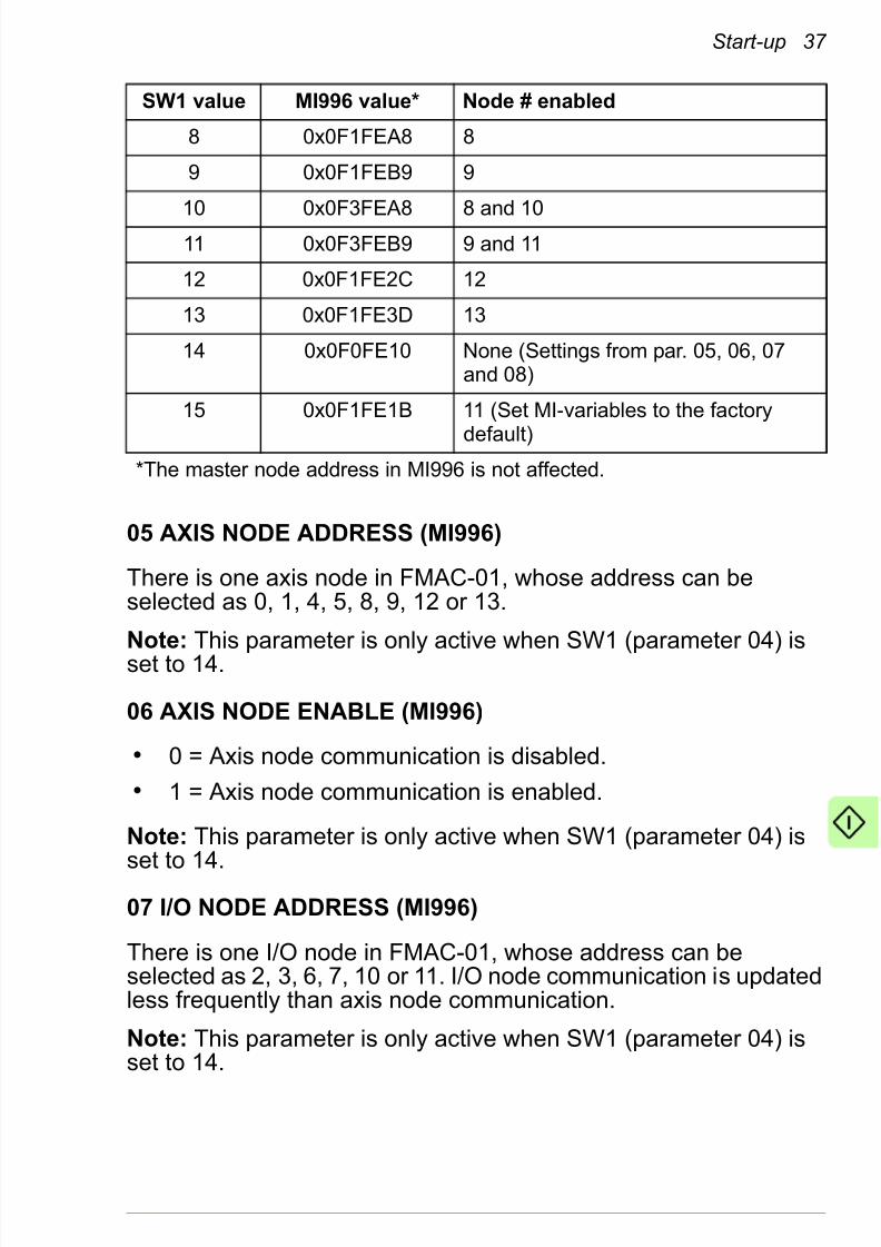
832019 Optic Profibus Manual
httpslidepdfcomreaderfulloptic-profibus-manual 5078
50 Start-up
Parameter setting examples ndash Drive control
5104 SW1 2 Enables nodes 0 and 2
5121 RAWREFERENCE SCALE
8 Defines that the torquereference sent by the master
is multiplied by 8 beforepassed to the drive
5122 CYCLICPOSITIONFEEDBACK FORMAT
1 Defines that there will be noshifting of the positionfeedback value
5127 FBA PARREFRESH
1 = REFRESH Validates the FMAC-01configuration parameters
Drive parameter Setting Description
1001 EXT1 STARTFUNC
3 = FBA Allows the drive to be startedby the adapter module
2201 SPEED FB SEL Enc1 speed Selects the actual speedmeasured by encoder 1 asthe speed feedback
3201 TORQ REF1SEL
3 = FBA REF1 Selects the fieldbus REF1input as TORQUE REF1
3401 EXT1EXT2 SEL CFalse Selects EXT1 as the controllocation
3403 EXT1 CTRLMODE1
2 = Torque Selects the Torque controlmode for EXT1
5709 KERNEL SYNC
MODE
2 = FBSync Keeps the drive in sync with
the servo clock
6001 POS ACT SEL 0 = ENC1 Selects ENC1 as the sourcefor the position feedback
6009 POSRESOLUTION
18 bits Sets the number of bits for theresolution of one revolution
Drive parameter Setting Description
832019 Optic Profibus Manual
httpslidepdfcomreaderfulloptic-profibus-manual 5178
Start-up 51
Parameter setting examples ndash Resolver
configuration
The table below shows an example set of parameters that youneed to set when using the resolver as encoder 1 for position
control When setting these parameters check the correct resolver parameter values from the resolver used in the application
Drive parameter Setting Description
9001 ENCODER 1SEL
5 = FEN-21 RES Activates communicationbetween the encoder moduleand the drive
9201 RESOLV
POLEPAIRS
eg 1 Sets the number of polepairs
used in the resolver9202 EXC SIGNALAMPL
eg 70 Vrms Defines the amplitude of theexcitation signal used in theresolver
9203 EXC SIGNALFREQ
eg 10 kHz Defines the frequency of theexcitation signal used in theresolver
9010 ENC PAR
REFRESH
1 = Configure Validates the encoder
configuration parameters
832019 Optic Profibus Manual
httpslidepdfcomreaderfulloptic-profibus-manual 5278
52 Start-up
Parameter setting examples ndash Home position
capture with homing switch
The table below shows an example set of parameters that youneed to set when a home switch is used for homing The
parameters enable the cyclic correction mode in the drive whichcaptures a position value to parameter 0403 PROBE1 POS MEASevery time the load passes the home switch It is assumed that thecapture triggers are connected to encoder DI1 and that theencoder in use is ENC1
Note Both trigger probe inputs must be taken from the samesource for proper operation of the capture status flag
Drive parameter Setting Description
5011 FBA SW B15SRC
P061108(POS CORRSTATUS bit 8LATCH1 DONE)
Sets par 0611 bit 8 LATCH1DONE as the source of FBAMAIN SW bit 31
(This setting causes thecapturing to use probe 1 If using probe 2 set par 0611bit 9 LATCH2 DONE as thesource)
6201 HOMINGMETHOD
0 = No Method Disables the driversquos internalhoming methods allowing thehome control from the master
6214 CYCLIC CORRMODE
4 = 2 Probe Dist Takes two capture triggersinto use
6215 TRIG PROBE1 1 = ENC1 DI1_- Sets the rising edge of DI1 inencoder 1 as the capturetrigger for the home position
6217 TRIG PROBE2 1 = ENC1 DI1_-
6219 MAXCORRECTION
0 Disables the drives internalcyclic position correction
6220 POS ACTOFFSET
0 Sets the absolute positionmeasured by the encoder asthe actual position of thedrive
832019 Optic Profibus Manual
httpslidepdfcomreaderfulloptic-profibus-manual 5378
Start-up 53
Parameter setting examples ndash Home position
capture with emulated zero pulse
This example shows how to use an emulated zero pulse for homeposition capture The encoder emulation mode can be configuredto generate an emulated zero pulse from the resolvers actualposition within one revolution To enable the emulated zero pulseyou need
bull FEN-21 resolver interface modules with revision D or newer
bull FEN-xx logic version VIExx500 or newer
bull ACSM1 drive with a firmware version newer than UMFI1510
The table below shows an example set of parameters that youneed to set to enable encoder emulation and the emulated zeropulse
Note Both trigger probe inputs must be taken from the samesource for proper operation of the capture status flag
6230 PROBE TRIGFILT
3 = 1000 us Determines how long thehome switch signal detectedby encoder DI1 must stay onbefore it is used to capture the
positionNote Parameter 6201 HOMING METHOD is reserved for the driversquosinternal homing methods If this parameter is set to a selection other thanlsquoNo Methodrsquo it will override the selections made in the table above andperform the drives internal homing method instead
Drive parameter Setting Description
5011 FBA SW B15SRC
P061108(POS CORRSTATUS bit 8LATCH1 DONE)
Sets par 0611 bit 8 LATCH1DONE as the source of FBAMAIN SW bit 31
(This setting causes thecapturing to use probe 1 If using probe 2 set par 0611bit 9 LATCH2 DONE as thesource)
9003 EMUL MODESEL
8 = FEN-21 RES Enables the TTL emulationfrom the resolver input
Drive parameter Setting Description
832019 Optic Profibus Manual
httpslidepdfcomreaderfulloptic-profibus-manual 5478
54 Start-up
9321 EMUL PULSENR
eg 1024 Sets the pulse number for theTTL emulation
9323 EMUL POS
OFFSET
eg 05 Sets the offset of the zero
pulse in relation to theabsolute position 0hellip1
9010 ENC PARREFRESH
1 = Configure Validates the encoder configuration parameters
6201 HOMINGMETHOD
0 = No Method Disables the driversquos internalhoming methods allowing thehome control from the master
6214 CYCLIC CORRMODE 4 = 2 Probe Dist Takes two capture triggersinto use
6215 TRIG PROBE1 eg 6 = ENC1Zerop
Triggering input with zeropulse according to your need(for more information see thedrive Firmware manual )
6217 TRIG PROBE2 eg 6 = ENC1Zerop
6219 MAXCORRECTION
0 Disables the drives internalcyclic position correction
6220 POS ACTOFFSET
0 Sets the absolute positionmeasured by the encoder asthe actual position of thedrive
6225 Z-PULSESOURCE 1
3 = Emulated Zp
Selects the source of the zeropulse6226 Z-PULSE
SOURCE 23 = Emulated Zp
6230 PROBE TRIGFILT
3 = 1000 us Determines how long thehome switch signal detectedby encoder DI1 must stay onbefore it is used to capture theposition
Note Parameter 6201 HOMING METHOD is reserved for the driversquosinternal homing methods If this parameter is set to a selection other thanlsquoNo Methodrsquo it will override the selections made in the table above andperform the drives internal homing method instead
Drive parameter Setting Description
832019 Optic Profibus Manual
httpslidepdfcomreaderfulloptic-profibus-manual 5578
Start-up 55
Parameter setting examples ndash End limit inputs
This example shows how the drives digital inputs can be used asend limit inputs in a MACRO status flag It is assumed that
bull the positive end limit switch is connected to the drives DI1
bull the negative end limit switch is connected to the drives DI2
The drives actual signal indicates the digital input status in packedboolean format For example parameter 0201 DI STATUS =000001 indicates that digital input DI1 is active and the other digitalinputs are inactive See the drive manuals for more details
To use DI1 as the positive end limit input the status of DI1 needsto be connected to parameter 0213 FBA MAIN SW bit 29 To use
DI2 as the negative end limit input the status of DI2 needs to beconnected to parameter 0213 FBA MAIN SW bit 30 To assign thepre-selected bits correctly set the parameters in the table below
Drive parameter Setting Description
5009 FBA SW B13SRC
DI STATUS Routes the status of digitalinput to 0213 FBA MAINSW bit 29
5010 FBA SW B14SRC
DI STATUS Routes the status of digitalinput to 0213 FBA MAINSW bit 30
832019 Optic Profibus Manual
httpslidepdfcomreaderfulloptic-profibus-manual 5678
56 Start-up
Configuring the master system
After the adapter module has been initialized by the drive themaster system must be prepared for communication with themodule
Configuring Delta Tau Turbo PMAC
This example shows how to configure a Delta Tau Turbo PMACmaster for communication with two ACSM1 drives assigned asaxis nodes 0 and 1 in the MACRO network The example is carriedout using the Terminal Window in the PeWinPro2 program If youare using another master system consult its manual for information on configuring the network
To set up the master in PeWinPro2 type the following commandsin the Terminal Window
Command Description
$$$ Resets the MACRO master and restores it to thefactory default values
I6800 = 5895 10 kHz Max Phase Clock
I6802 = 4 2 kHz Servo Clock
Note It is crucial for the ACSM1 to perform properlythat the servo clock is set to 2 kHz
I10 = 4193066 Servo interruption time (83886082kHz)
I78 = 32 MasterSlave communication timeout (in servo cycles)
I79 = 32 MasterMaster communication timeout (in servocycles)
I80 = 45 MACRO Ring check period (in servo cycles)
I81 = 2 MACRO Maximum ring error count
I82 = 13 MACRO Minimum sync packet count
I70 = 3 MACRO IC 0 master 0 node auxiliary register enablefor nodes 0 and 1
I71 = 3 Node protocol type selection Set MACRO protocoltype as 1 for nodes 0 and 1 in MACRO IC master 0
I100 = 1 Motor 1 ActivationI200 = 1 Motor 2 Activation
832019 Optic Profibus Manual
httpslidepdfcomreaderfulloptic-profibus-manual 5778
Start-up 57
For more information on the commands used in the Delta TauTurbo PMAC master refer to the software reference manual of Turbo PMACPMAC2
I124 = $840001 Motor 1 Flag mode control
I224 = $840001 Motor 2 Flag mode control
I6840 = $4030 MACRO IC 0 Ring configurationstatusI6841 = $0FC003 MACRO IC 0 Node activation control
Note This value activates only nodes 0 1 14 and 15
SAVE Saves the variables
$$$ Resets the master while using the saved variables
These values have to be adjusted if more slave nodes are present on thering
Command Description
832019 Optic Profibus Manual
httpslidepdfcomreaderfulloptic-profibus-manual 5878
58 Start-up
832019 Optic Profibus Manual
httpslidepdfcomreaderfulloptic-profibus-manual 5978
Communication profiles 59
Communication profiles
What this chapter contains
This chapter describes the communication profile used in thecommunication between the MACRO network the adapter module and the drive
Communication profiles
Communication profiles are ways of conveying control commands(Control word Status word References and Actual values)between the master station and the drive
With the FMAC-01 MACRO adapter module the master employsthe MACRO Station profile The profile is converted to the FBAprofile by the adapter module The FBA profile is detailed in thedrive manuals
832019 Optic Profibus Manual
httpslidepdfcomreaderfulloptic-profibus-manual 6078
60 Communication profiles
MACRO Station profile
The MACRO Station profilersquos control and status flags are handledby the adapter module The figure below shows how the controland status flag correlate with the driversquos internal ControlStatus
word
1) FBA CW = xxxx xxxx xxxx xxx0 xxxx 1xx0 1xxx xx01
Start inhibit = 0 Remote Cmd = 1 Reset = 0 Run Enable = 1 Start = 0Stop = 1
2) Flag command Bit 14 Amp enable = 1
3) Flag command Bit 14 Amp enable = 0
4) FBA CW = xxxx xxxx xxxx xxx0 xxxx 1xx0 1xxx xx10Start inhibit = 0 Remote Cmd = 1 Reset = 0 Run Enable = 1 Start = 1Stop = 0
5) FBA SW Bit 6 Ack Start Inhibit = 0
6) Flag status Bit 15 Station Fault = 1
FAULT
OPERATING
IDLE
STARTINHIBITED
Power on
Fault
1)
3) 2)
4)
5)
6)
7)
8)9)
832019 Optic Profibus Manual
httpslidepdfcomreaderfulloptic-profibus-manual 6178
Communication profiles 61
MACRO Station control and status flags
The table below shows the contents the MACRO Station controlflag
7) Flag command Bit 12 Node Reset = 1 -gt FBA CW Bit 8 = 1 (Reset = 1)
8) FBA SW Bit 6 Ack Start Inhibit = 1
9) Flag command Bit 14 Amp enable = 0
Bit Description
23 UserCmdFlg5
22 UserCmdFlg4
21 UserCmdFlg3
20 UserCmdFlg2
19 UserCmdFlg1
18 Reserved
17 Reserved
16 Reserved
15 Station fault (when bit 13 is set to 1)
14 Amplifier Enable
13 This slave detected a MACRO ring break and became aSynchronizing master
12 Node Reset command (Clear faults)
11 Position Capture (Triggered Event) Enable Flag
10 0 indicates a Command Message and not a Status Message
9 Reserved
8 Reserved
7-0 Not available
832019 Optic Profibus Manual
httpslidepdfcomreaderfulloptic-profibus-manual 6278
62 Communication profiles
The table below shows the contents of the MACRO Station statusflag
Bit Description
23 UserStatusFlg5
22 UserStatusFlg4
21 UserStatusFlg3
20 UserStatusFlg2
19 UserStatusFlg1
18 Negative End Limit Flag (NILMn) Input Value
17 Positive End Limit Flag (PILMn) Input Value
16 Home Flag (HMFLn) Input Value
15 Amplifier or Station Node shutdown Fault
14 Amplifier Enabled
13 This Node detected a MACRO Ring Break
12 A Reset has occurred This bit is cleared on the next Amplifier Enable
11 Position Capture (Triggered Event) Occurred Flag10 1 indicates a Status Message and not a Command Message
9 Reserved
8 Reserved
7-0 Not available
832019 Optic Profibus Manual
httpslidepdfcomreaderfulloptic-profibus-manual 6378
Communication protocol 63
Communication protocol
What this chapter contains
This chapter describes the communication on a MACRO network
MACRO protocol
MACRO is an Ethernet-style protocol that uses multi-mode fiber optic (FDDI-PMD ISOIEC 9314-3) or twisted pair copper (CAT5)called 100BASEFX and 100BASETX
MACRO frame structure
Each data packet for a node contains four registers 0 1 2 and 3
bull Register 0 is a 24-bit register for real time data
bull Registers 1 2 and 3 are 16-bit registers for real-time data
Each node has a command packet of four registers and a feedbackpacket of four registers The command and feedback packets slipinto the same data packet for the node (upon entering theaddressed node the data packet is a command packet uponexiting it is a feedback packet)
832019 Optic Profibus Manual
httpslidepdfcomreaderfulloptic-profibus-manual 6478
64 Communication protocol
Services
The MACRO protocol has the ability to pass commands of differenttypes from a controller to a drive Thanks to the high rate of datatransmission over the ring (125 Mbitssec) MACRO facilitates the
closure of high performance servo loops across the ring allowingthe controller and the drive to split the motion control tasksbetween themselves at any level
MACRO specifies services for reading and writing data from thephysical memory within the slaves The FMAC-01 MACRO adapter module supports the following MACRO services
bull Writing and reading drive parameters
bull Axis node MACRO 72-bit cyclic IO format
bull Fast digital output transfer in Control word
bull Home position position capture and over travel limits
bull IO node MACRO 72-bit cyclic IO format
bull Absolute power-on position
bull Flag capture position
bull ASCII transfer commands
Writing and reading drive parameters
Writing parameter values to the drive is performed in two phasesIn the first phase the master writes the group and parameter number to MI30 In the second phase the master writes the data tobe written to MI31 If a writing error occurs the slave returns anerror by setting bit 18 of the node 15 status
Likewise reading parameter values from the drive is performed intwo phases In the first phase the master writes the group andparameter number to MI30 In the second phase the data is readby the master from MI31 If a reading error occurs the slavereturns an error by setting bit 18 of the node 15 status
832019 Optic Profibus Manual
httpslidepdfcomreaderfulloptic-profibus-manual 6578
Communication protocol 65
The table below shows the MI30 bit definitions
The parameter group and index number have to be in hexadecimalformat For example to read parameter 5101
bull Group = 51 decimal = 33 hexadecimal
bull Index = 1 decimal = 1 hexadecimal
bull MI30 = $3301
Axis node MACRO 72-bit cyclic IO format
The 72-bit node cyclic transfer is used to control the drive With theACSM1 drive the command data at the drive is updated at 500microsecond intervals The payload data comprises one 24-bitsegment and three 16-bit segments
The data transferred in axis node communication is selected indrive parameter group 50 by defining the reference control modesand actual values used in the application For typical MACROmotion control applications the parameter settings should be asfollowsbull 5004 FBA REF1 MODESEL = Raw data
bull 5005 FBA REF2 MODESEL = Position
bull 5006 FBA ACT1 TR SRC = P0403 (PROBE1 POS MEAS) or
P0404 (PROBE2 POS MEAS)
Bit Definition
4716 Unused
158 Parameter group number (0hellip255)
70 Parameter index number (0hellip255)
Direction Register 0 (24-bit) 1 (16-bit) 2 (16-bit) 3 (16-bit)
Master toFMAC-01
REF1(Torquevelocity
command)
Unused Unused Flagcommand
FMAC-01 toMaster
ACT2(Positionfeedback)
ACT1(Flag captured position)
Flag status
832019 Optic Profibus Manual
httpslidepdfcomreaderfulloptic-profibus-manual 6678
66 Communication protocol
With these settings the 24-bit MACRO torque command istranslated into the 32-bit drive-internal reference (REF1) The 24-bit MACRO position feedback (MI920) is translated from the 32-bitdrive-internal actual value (ACT2) The MACRO flag capturedposition (MI921) is translated from the 32-bit drive-internal actual
value (ACT1)It is also possible to use alternative settings for the referencecontrol modes Since there is no control mode selection throughthe MACRO variables parameter 5004 FBA REF1 MODESELdetermines how to scale the reference data depending on whatmode is in use Valid modes are torque speed and raw data modeNote that the selected reference control mode also affects thefeedback value transferred in ACT1
bull In the torque mode the maximum MACRO torque command is
scaled to a value of 10000 of the nominal torque The
feedback transferred in ACT1 is the motor torque in percent of
the motor nominal torque
bull In the speed mode the scaling is determined by parameter
2502 SPEED SCALING The feedback transferred in ACT1 is
the filtered actual speed in rpm
bull In the raw data mode the scaling is determined by theFMAC-01 configuration parameter 21 RAW REFERENCE
SCALE The feedback transferred in ACT1 is selected with
parameter 5006 FBA ACT1 TR SRC
Even though reference 2 is not used in axis node communicationparameter 5005 FBA REF2 MODESEL defines the feedbacktransferred in ACT2 from the drive to the master With the MACROinterface this parameter should always be set to lsquoPositionrsquo This
setting transfers the drives actual position as feedback in ACT2The scaling of the position feedback is determined by the FMAC-01 configuration parameter 22 CYCLIC POSITION FEEDBACKFORMAT However the most significant 8 bits of the drives ACT2are always discarded
The actual drive control mode is selected with drive parameters3401 EXT1EXT2 SEL 3402 EXT1 MODE 12 SEL 3403 EXT1CTRL MODE1 and 3404 EXT1 CTRL MODE2 For further information see the drive Firmware manual and the parameter setting examples in section Starting up the ACSM1 drive on page47
832019 Optic Profibus Manual
httpslidepdfcomreaderfulloptic-profibus-manual 6778
Communication protocol 67
Fast digital output transfer in Control word
Four freely programmable bits in the FBA MAIN CW can be usedto transfer fast digital outputs as follows
To use the freely programmable bits from the FBA MAIN CW in thedrive bits 28 29 30 or 31 of parameter 0212 FBA MAIN CW haveto be mapped to the bit in the parameter to be controlled
Example To map bit 28 of the FBA MAIN CW to the first digitaloutput (DIO1) set parameter 1204 DIO1 OUT PTR to P021228(0212 FBA MAIN CW bit 28)
Home position position capture and overtravel
limits
The MACRO flag status bits are mapped to the drive FBA MAINSW as shown in the table below
Digitaloutput 1
Digitaloutput 2
Digitaloutput 3
Digitaloutput 4
FBAMAIN CW
CW B28 CW B29 CW B30 CW B31
MACROFlagcommand
B19 -UserCmdFlg1
B20 -UserCmdFlg2
B21 -UserCmdFlg3
B22 -UserCmdFlg4
Homeposition
Positiveover travel
Negativeover travel
Positioncapture
FBA MAIN SW SW B28 SW B29 SW B30 SW B31
MACRO Flagstatus
B16 - HomeFlag
(HMFLn)Input Value
B17 -Positive
End LimitFlag
(PILMn)Input Value
B18 -NegativeEnd Limit
Flag(NILMn)
Input Value
B11 -Position
Captured(Triggered
EventOccurred)
Flag
832019 Optic Profibus Manual
httpslidepdfcomreaderfulloptic-profibus-manual 6878
68 Communication protocol
The captured position will be sent from the drive to the adapter module using ACT1 For this to work an appropriate driveparameter has to be mapped to parameter 5006 FBA ACT1 TRSRC For the mapping parameter 5004 FBA REF1 MODESELhas to be set to lsquoRaw datarsquo See the parameter setting examples in
section Starting up the ACSM1 drive on page 47
IO node MACRO 72-bit cyclic IO format
The 72-bit node cyclic transfer is used to transfer parameter-mapped data to and from the drive (parameter groups 52 and 53)Low priority cyclic data is updated at 2 ms intervals The payloaddata comprises one 24-bit segment and three 16-bit segments
If the actual data is smaller than the payload segment the data isplaced in the least significant byte(s)
Absolute power-on position
MI-variable MI920 contains the drives actual position read fromdrive parameter 0112 POS ACT The position value of the drive isshown in MACRO format in MI920
Flag capture position
MI-variable MI921 contains the latest captured position value
DirectionRegister
0 (24-bit) 1 (16-bit) 2 (16-bit) 3 (16-bit)
Master toFMAC-01
5301 FBADATA OUT1
5302 FBADATA OUT2
5303 FBADATA OUT3
5304 FBADATA OUT4
FMAC-01 toMaster
5201 FBADATA IN1
5202 FBADATA IN2
5203 FBADATA IN3
5204 FBADATA IN4
832019 Optic Profibus Manual
httpslidepdfcomreaderfulloptic-profibus-manual 6978
Communication protocol 69
ASCII transfer commands
Node 14 is used to transfer 48-bit ASCII commands from themaster These commands are transmitted using the broadcastfeature of the MACRO protocol
The table below lists all ASCII commands supported by FMAC-01
ASCII command Explanation Type
MACSTAx Initiates ASCII communicationbetween the master station andthe selected slave station x
Reports the MACRO StationGlobal Status register (MI4)
Unsigned 32-bitinteger
$$$ Resets the MACRO station andrestores all station MI-variablesto their last saved values
$$$ Resets the MACRO station andrestores all station MI-variablesto their factory default values
BKUP Reports all saved MI-variables ASCII string
CID Reports the MACRO stationrsquospart number (CardID) Unsigned 32-bitinteger
CLRF Clears all faults on the MACROstation and prepares it for further operation
DATE Reports the date of the firmware MonthDayYear
SAVE Copies the MACRO stationrsquosMI-variable values from the
volatile active memory to thenon-volatile flash memory
SID Reports the serial number of theMACRO station
Unsigned 32-bitinteger
TYPE Reports the MACRO station type(ldquouMacrordquo)
ASCII string
VERS Reports the firmware versionnumber
0001 9999(BCD)
832019 Optic Profibus Manual
httpslidepdfcomreaderfulloptic-profibus-manual 7078
70 Communication protocol
Ring order set-up
Upon the initial binding of a MACRO station to a MACRO masterthe ring order set-up is used if FMAC-01 configuration parameter 06 (STATION ORDER NUMBER) is set to 0 Otherwise parameter 03 (SW1) or parameters 04 05 and 06 (MASTER ADDRESSAXIS NODE ADDRESS and IO NODE ADDRESS) are used to setup the axis and IO nodes and the master
In the ring order set-up the ring controller sends out a commandon the ring in the ASCII communication protocol asking to talk tothe first MACRO station that does not have a station number Oncethe communication is established the ring controller can define theMACRO binding of the slave station to a master and their bindingnode(s)
Timing and synchronization
The timing of the reference and actual position feedback isimportant in a MACRO network The rate at which referencesshould be fed and position feedback read is determined by theservo clock rate (which is determined by the phase clock and servoclock divider set by MI990) The servo clock has to be set to 2 kHzThis value corresponds to the hexadecimal value 0x13880444 of MI990
In some applications it may be beneficial that all drives in the ringare internally synchronized with each other To start thesynchronization send an ldquomsyncrdquo command from the MACROmaster
VID Reports the MACRO stationrsquosvendor identification number (6 ABB)
ASCII string
ASCII command Explanation Type
832019 Optic Profibus Manual
httpslidepdfcomreaderfulloptic-profibus-manual 7178
Communication protocol 71
Acyclic and cyclic communication modes
The FMAC-01 MACRO adapter module supports the Type 1MACRO protocol One axis node and one IO node are supportedThe addresses available to the axis node are 0 1 4 5 8 9 12 or
13 to the IO node 2 3 6 7 10 or 11Nodes 14 and 15 are used for acyclic communication Node 14 isused for 48-bit broadcast ASCII transfer Node 15 is used by themaster to readwrite the MI-variables
MI-variables supported by FMAC-01
MI-variable Name RORW FMAC-01configurationparameter (group 51)
MI0 Station Firmware Version RO 10
MI1 Station Firmware Date RO
MI2 Station ID and User Configuration Word
RW 11 12
MI3 SW1 and SW2 RW 03 04
MI4 Station Status Word RO 13MI5 Ring Error Counter RW 18 19
MI8 MACRO Ring CheckPeriod
RW 14
MI9 MACRO Ring Error Shutdown Count
RW 15
MI10 MACRO Sync Packet
Shutdown Count
RW 16
MI11 Station Order Number RW 09
MI12 Card Identification RO
MI20 Cyclic PositionFeedback Format
RW 22
MI30 Drive parameter groupindex
RW
MI31 Drive parameter data RW
832019 Optic Profibus Manual
httpslidepdfcomreaderfulloptic-profibus-manual 7278
72 Communication protocol
MI920 Absolute Power-On
Position
RO 22
MI921 Flag Capture Position RO 22
MI990 Clock Control Register RW 19 20
MI992 MaxPhase FrequencyControl
RW 19 20
MI993 Servo Encoder ClockDivisor
RW 19 20
MI994 Flag Clock Divisor RW 19 20MI995 MACRO Ring
ConfigurationStatusRW 17
MI996 MACRO Node ActivateControl
RW 03 04 05 06 07 08
MI998 Servo Clock FrequencyControl
RW
MI-variable Name RORW FMAC-01configurationparameter (group 51)
832019 Optic Profibus Manual
httpslidepdfcomreaderfulloptic-profibus-manual 7378
Diagnostics 73
Diagnostics
What this chapter contains
This chapter explains how to trace faults with the status LEDs onthe adapter module
LED indications
The adapter module is equipped with three bicolor diagnosticLEDs The LEDs are described below
Name Color Function
HOST
Blinking green Establishing communication tohost
Green Connection to host OKBlinking red Communication to host lost
temporarily
832019 Optic Profibus Manual
httpslidepdfcomreaderfulloptic-profibus-manual 7478
74 Diagnostics
A station fault is triggered if
bull a ring break occurs
bull the number of ring communication errors exceeds the MACRO
ring error shutdown count defined by par 15 (MI9)
bull the number of sync packets falls short of the MACRO sync
packet shutdown count defined by par 16 (MI10) during the
check period defined by par 14 (MI8)
bull another station is on the same node number
For the descriptions of the FMAC-01 configuration parametersabove see page 39
MODULE
Off (dark) Configuration not done Nonodes selected to be active
Green Ring active no faults
Blinking green Module in ASCII mode
Red Ring break detected
Blinking red Station fault or drive fault
NET Green MACRO link OK
Red MACRO link down
Name Color Function
832019 Optic Profibus Manual
httpslidepdfcomreaderfulloptic-profibus-manual 7578
Technical data 75
Technical data
What this chapter contains
This chapter contains the technical data of the adapter module andthe MACRO link
FMAC-01
The figure below shows the enclosure of the adapter module fromthe front and side
832019 Optic Profibus Manual
httpslidepdfcomreaderfulloptic-profibus-manual 7678
76 Technical data
MACRO link
Mounting Into the option slot of the drive
Degree of protection IP20
Ambient conditions The applicable ambient conditions specified for the drive in its manuals are in effect
Indicators Three bicolor LEDs (HOST MODULE NET)
Connectors 20-pin connector to the drive (X3)
Two SC fiber optic connectors (X1 and X2)
Power supply +33 V plusmn 5 max 450 mA (supplied by the drive)
General Estimated min lifetime 100 000 h
All materials ULCSA-approved
Complies with EMC standard EN 61800-32004
Medium Fiber optic
bull Wiring FDDI-PMD ISOIEC 9314-3
bull Connector SC
bull Maximum segment length 3000 m
Topology Ring
Transfer rate Up to 125 Mbits
Serial communicationtype
Full duplex
Protocol MACRO
832019 Optic Profibus Manual
httpslidepdfcomreaderfulloptic-profibus-manual 7778
Further information
Product and service inquiries
Address any inquiries about the product to your local ABBrepresentative quoting the type designation and serial number of
the unit in question A listing of ABB sales support and service
contacts can be found by navigating to wwwabbcomdrives and
selecting Sales Support and Service network
Product training
For information on ABB product training navigate to wwwabbcomdrives and select Training courses
Providing feedback on ABB Drives manuals
Your comments on our manuals are welcome Go to
wwwabbcomdrives and select Document Library ndash Manuals
feedback form (LV AC drives)
Document library on the Internet
You can find manuals and other product documents in PDF format
on the Internet Go to wwwabbcomdrives and select Document
Library You can browse the library or enter selection criteria for
example a document code in the search field
832019 Optic Profibus Manual
httpslidepdfcomreaderfulloptic-profibus-manual 7878
Contact us
ABB Oy
DrivesPO Box 184FI-00381 HELSINKIFINLANDTelephone +358 10 22 11Fax +358 10 22 22681wwwabbcomdrives
ABB Inc
Automation TechnologiesDrives amp Motors16250 West Glendale DriveNew Berlin WI 53151USATelephone 262 785-3200
1-800-HELP-365Fax 262 780-5135wwwabbcomdrives
ABB Beijing Drive Systems
Co LtdNo 1 Block DA-10 Jiuxianqiao BeiluChaoyang DistrictBeijing PR China 100015Telephone +86 10 5821 7788Fax +86 10 5821 7618wwwabbcomdrives
3
A U A 0 0 0 0 0 8 9 4 3 1 R e v A
( E N ) 2 0 1 0 - 1 2 - 0 3
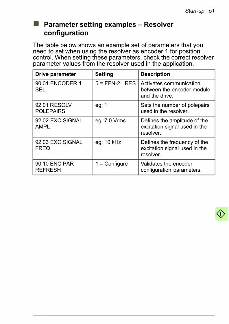
832019 Optic Profibus Manual
httpslidepdfcomreaderfulloptic-profibus-manual 5378
Start-up 53
Parameter setting examples ndash Home position
capture with emulated zero pulse
This example shows how to use an emulated zero pulse for homeposition capture The encoder emulation mode can be configuredto generate an emulated zero pulse from the resolvers actualposition within one revolution To enable the emulated zero pulseyou need
bull FEN-21 resolver interface modules with revision D or newer
bull FEN-xx logic version VIExx500 or newer
bull ACSM1 drive with a firmware version newer than UMFI1510
The table below shows an example set of parameters that youneed to set to enable encoder emulation and the emulated zeropulse
Note Both trigger probe inputs must be taken from the samesource for proper operation of the capture status flag
6230 PROBE TRIGFILT
3 = 1000 us Determines how long thehome switch signal detectedby encoder DI1 must stay onbefore it is used to capture the
positionNote Parameter 6201 HOMING METHOD is reserved for the driversquosinternal homing methods If this parameter is set to a selection other thanlsquoNo Methodrsquo it will override the selections made in the table above andperform the drives internal homing method instead
Drive parameter Setting Description
5011 FBA SW B15SRC
P061108(POS CORRSTATUS bit 8LATCH1 DONE)
Sets par 0611 bit 8 LATCH1DONE as the source of FBAMAIN SW bit 31
(This setting causes thecapturing to use probe 1 If using probe 2 set par 0611bit 9 LATCH2 DONE as thesource)
9003 EMUL MODESEL
8 = FEN-21 RES Enables the TTL emulationfrom the resolver input
Drive parameter Setting Description
832019 Optic Profibus Manual
httpslidepdfcomreaderfulloptic-profibus-manual 5478
54 Start-up
9321 EMUL PULSENR
eg 1024 Sets the pulse number for theTTL emulation
9323 EMUL POS
OFFSET
eg 05 Sets the offset of the zero
pulse in relation to theabsolute position 0hellip1
9010 ENC PARREFRESH
1 = Configure Validates the encoder configuration parameters
6201 HOMINGMETHOD
0 = No Method Disables the driversquos internalhoming methods allowing thehome control from the master
6214 CYCLIC CORRMODE 4 = 2 Probe Dist Takes two capture triggersinto use
6215 TRIG PROBE1 eg 6 = ENC1Zerop
Triggering input with zeropulse according to your need(for more information see thedrive Firmware manual )
6217 TRIG PROBE2 eg 6 = ENC1Zerop
6219 MAXCORRECTION
0 Disables the drives internalcyclic position correction
6220 POS ACTOFFSET
0 Sets the absolute positionmeasured by the encoder asthe actual position of thedrive
6225 Z-PULSESOURCE 1
3 = Emulated Zp
Selects the source of the zeropulse6226 Z-PULSE
SOURCE 23 = Emulated Zp
6230 PROBE TRIGFILT
3 = 1000 us Determines how long thehome switch signal detectedby encoder DI1 must stay onbefore it is used to capture theposition
Note Parameter 6201 HOMING METHOD is reserved for the driversquosinternal homing methods If this parameter is set to a selection other thanlsquoNo Methodrsquo it will override the selections made in the table above andperform the drives internal homing method instead
Drive parameter Setting Description
832019 Optic Profibus Manual
httpslidepdfcomreaderfulloptic-profibus-manual 5578
Start-up 55
Parameter setting examples ndash End limit inputs
This example shows how the drives digital inputs can be used asend limit inputs in a MACRO status flag It is assumed that
bull the positive end limit switch is connected to the drives DI1
bull the negative end limit switch is connected to the drives DI2
The drives actual signal indicates the digital input status in packedboolean format For example parameter 0201 DI STATUS =000001 indicates that digital input DI1 is active and the other digitalinputs are inactive See the drive manuals for more details
To use DI1 as the positive end limit input the status of DI1 needsto be connected to parameter 0213 FBA MAIN SW bit 29 To use
DI2 as the negative end limit input the status of DI2 needs to beconnected to parameter 0213 FBA MAIN SW bit 30 To assign thepre-selected bits correctly set the parameters in the table below
Drive parameter Setting Description
5009 FBA SW B13SRC
DI STATUS Routes the status of digitalinput to 0213 FBA MAINSW bit 29
5010 FBA SW B14SRC
DI STATUS Routes the status of digitalinput to 0213 FBA MAINSW bit 30
832019 Optic Profibus Manual
httpslidepdfcomreaderfulloptic-profibus-manual 5678
56 Start-up
Configuring the master system
After the adapter module has been initialized by the drive themaster system must be prepared for communication with themodule
Configuring Delta Tau Turbo PMAC
This example shows how to configure a Delta Tau Turbo PMACmaster for communication with two ACSM1 drives assigned asaxis nodes 0 and 1 in the MACRO network The example is carriedout using the Terminal Window in the PeWinPro2 program If youare using another master system consult its manual for information on configuring the network
To set up the master in PeWinPro2 type the following commandsin the Terminal Window
Command Description
$$$ Resets the MACRO master and restores it to thefactory default values
I6800 = 5895 10 kHz Max Phase Clock
I6802 = 4 2 kHz Servo Clock
Note It is crucial for the ACSM1 to perform properlythat the servo clock is set to 2 kHz
I10 = 4193066 Servo interruption time (83886082kHz)
I78 = 32 MasterSlave communication timeout (in servo cycles)
I79 = 32 MasterMaster communication timeout (in servocycles)
I80 = 45 MACRO Ring check period (in servo cycles)
I81 = 2 MACRO Maximum ring error count
I82 = 13 MACRO Minimum sync packet count
I70 = 3 MACRO IC 0 master 0 node auxiliary register enablefor nodes 0 and 1
I71 = 3 Node protocol type selection Set MACRO protocoltype as 1 for nodes 0 and 1 in MACRO IC master 0
I100 = 1 Motor 1 ActivationI200 = 1 Motor 2 Activation
832019 Optic Profibus Manual
httpslidepdfcomreaderfulloptic-profibus-manual 5778
Start-up 57
For more information on the commands used in the Delta TauTurbo PMAC master refer to the software reference manual of Turbo PMACPMAC2
I124 = $840001 Motor 1 Flag mode control
I224 = $840001 Motor 2 Flag mode control
I6840 = $4030 MACRO IC 0 Ring configurationstatusI6841 = $0FC003 MACRO IC 0 Node activation control
Note This value activates only nodes 0 1 14 and 15
SAVE Saves the variables
$$$ Resets the master while using the saved variables
These values have to be adjusted if more slave nodes are present on thering
Command Description
832019 Optic Profibus Manual
httpslidepdfcomreaderfulloptic-profibus-manual 5878
58 Start-up
832019 Optic Profibus Manual
httpslidepdfcomreaderfulloptic-profibus-manual 5978
Communication profiles 59
Communication profiles
What this chapter contains
This chapter describes the communication profile used in thecommunication between the MACRO network the adapter module and the drive
Communication profiles
Communication profiles are ways of conveying control commands(Control word Status word References and Actual values)between the master station and the drive
With the FMAC-01 MACRO adapter module the master employsthe MACRO Station profile The profile is converted to the FBAprofile by the adapter module The FBA profile is detailed in thedrive manuals
832019 Optic Profibus Manual
httpslidepdfcomreaderfulloptic-profibus-manual 6078
60 Communication profiles
MACRO Station profile
The MACRO Station profilersquos control and status flags are handledby the adapter module The figure below shows how the controland status flag correlate with the driversquos internal ControlStatus
word
1) FBA CW = xxxx xxxx xxxx xxx0 xxxx 1xx0 1xxx xx01
Start inhibit = 0 Remote Cmd = 1 Reset = 0 Run Enable = 1 Start = 0Stop = 1
2) Flag command Bit 14 Amp enable = 1
3) Flag command Bit 14 Amp enable = 0
4) FBA CW = xxxx xxxx xxxx xxx0 xxxx 1xx0 1xxx xx10Start inhibit = 0 Remote Cmd = 1 Reset = 0 Run Enable = 1 Start = 1Stop = 0
5) FBA SW Bit 6 Ack Start Inhibit = 0
6) Flag status Bit 15 Station Fault = 1
FAULT
OPERATING
IDLE
STARTINHIBITED
Power on
Fault
1)
3) 2)
4)
5)
6)
7)
8)9)
832019 Optic Profibus Manual
httpslidepdfcomreaderfulloptic-profibus-manual 6178
Communication profiles 61
MACRO Station control and status flags
The table below shows the contents the MACRO Station controlflag
7) Flag command Bit 12 Node Reset = 1 -gt FBA CW Bit 8 = 1 (Reset = 1)
8) FBA SW Bit 6 Ack Start Inhibit = 1
9) Flag command Bit 14 Amp enable = 0
Bit Description
23 UserCmdFlg5
22 UserCmdFlg4
21 UserCmdFlg3
20 UserCmdFlg2
19 UserCmdFlg1
18 Reserved
17 Reserved
16 Reserved
15 Station fault (when bit 13 is set to 1)
14 Amplifier Enable
13 This slave detected a MACRO ring break and became aSynchronizing master
12 Node Reset command (Clear faults)
11 Position Capture (Triggered Event) Enable Flag
10 0 indicates a Command Message and not a Status Message
9 Reserved
8 Reserved
7-0 Not available
832019 Optic Profibus Manual
httpslidepdfcomreaderfulloptic-profibus-manual 6278
62 Communication profiles
The table below shows the contents of the MACRO Station statusflag
Bit Description
23 UserStatusFlg5
22 UserStatusFlg4
21 UserStatusFlg3
20 UserStatusFlg2
19 UserStatusFlg1
18 Negative End Limit Flag (NILMn) Input Value
17 Positive End Limit Flag (PILMn) Input Value
16 Home Flag (HMFLn) Input Value
15 Amplifier or Station Node shutdown Fault
14 Amplifier Enabled
13 This Node detected a MACRO Ring Break
12 A Reset has occurred This bit is cleared on the next Amplifier Enable
11 Position Capture (Triggered Event) Occurred Flag10 1 indicates a Status Message and not a Command Message
9 Reserved
8 Reserved
7-0 Not available
832019 Optic Profibus Manual
httpslidepdfcomreaderfulloptic-profibus-manual 6378
Communication protocol 63
Communication protocol
What this chapter contains
This chapter describes the communication on a MACRO network
MACRO protocol
MACRO is an Ethernet-style protocol that uses multi-mode fiber optic (FDDI-PMD ISOIEC 9314-3) or twisted pair copper (CAT5)called 100BASEFX and 100BASETX
MACRO frame structure
Each data packet for a node contains four registers 0 1 2 and 3
bull Register 0 is a 24-bit register for real time data
bull Registers 1 2 and 3 are 16-bit registers for real-time data
Each node has a command packet of four registers and a feedbackpacket of four registers The command and feedback packets slipinto the same data packet for the node (upon entering theaddressed node the data packet is a command packet uponexiting it is a feedback packet)
832019 Optic Profibus Manual
httpslidepdfcomreaderfulloptic-profibus-manual 6478
64 Communication protocol
Services
The MACRO protocol has the ability to pass commands of differenttypes from a controller to a drive Thanks to the high rate of datatransmission over the ring (125 Mbitssec) MACRO facilitates the
closure of high performance servo loops across the ring allowingthe controller and the drive to split the motion control tasksbetween themselves at any level
MACRO specifies services for reading and writing data from thephysical memory within the slaves The FMAC-01 MACRO adapter module supports the following MACRO services
bull Writing and reading drive parameters
bull Axis node MACRO 72-bit cyclic IO format
bull Fast digital output transfer in Control word
bull Home position position capture and over travel limits
bull IO node MACRO 72-bit cyclic IO format
bull Absolute power-on position
bull Flag capture position
bull ASCII transfer commands
Writing and reading drive parameters
Writing parameter values to the drive is performed in two phasesIn the first phase the master writes the group and parameter number to MI30 In the second phase the master writes the data tobe written to MI31 If a writing error occurs the slave returns anerror by setting bit 18 of the node 15 status
Likewise reading parameter values from the drive is performed intwo phases In the first phase the master writes the group andparameter number to MI30 In the second phase the data is readby the master from MI31 If a reading error occurs the slavereturns an error by setting bit 18 of the node 15 status
832019 Optic Profibus Manual
httpslidepdfcomreaderfulloptic-profibus-manual 6578
Communication protocol 65
The table below shows the MI30 bit definitions
The parameter group and index number have to be in hexadecimalformat For example to read parameter 5101
bull Group = 51 decimal = 33 hexadecimal
bull Index = 1 decimal = 1 hexadecimal
bull MI30 = $3301
Axis node MACRO 72-bit cyclic IO format
The 72-bit node cyclic transfer is used to control the drive With theACSM1 drive the command data at the drive is updated at 500microsecond intervals The payload data comprises one 24-bitsegment and three 16-bit segments
The data transferred in axis node communication is selected indrive parameter group 50 by defining the reference control modesand actual values used in the application For typical MACROmotion control applications the parameter settings should be asfollowsbull 5004 FBA REF1 MODESEL = Raw data
bull 5005 FBA REF2 MODESEL = Position
bull 5006 FBA ACT1 TR SRC = P0403 (PROBE1 POS MEAS) or
P0404 (PROBE2 POS MEAS)
Bit Definition
4716 Unused
158 Parameter group number (0hellip255)
70 Parameter index number (0hellip255)
Direction Register 0 (24-bit) 1 (16-bit) 2 (16-bit) 3 (16-bit)
Master toFMAC-01
REF1(Torquevelocity
command)
Unused Unused Flagcommand
FMAC-01 toMaster
ACT2(Positionfeedback)
ACT1(Flag captured position)
Flag status
832019 Optic Profibus Manual
httpslidepdfcomreaderfulloptic-profibus-manual 6678
66 Communication protocol
With these settings the 24-bit MACRO torque command istranslated into the 32-bit drive-internal reference (REF1) The 24-bit MACRO position feedback (MI920) is translated from the 32-bitdrive-internal actual value (ACT2) The MACRO flag capturedposition (MI921) is translated from the 32-bit drive-internal actual
value (ACT1)It is also possible to use alternative settings for the referencecontrol modes Since there is no control mode selection throughthe MACRO variables parameter 5004 FBA REF1 MODESELdetermines how to scale the reference data depending on whatmode is in use Valid modes are torque speed and raw data modeNote that the selected reference control mode also affects thefeedback value transferred in ACT1
bull In the torque mode the maximum MACRO torque command is
scaled to a value of 10000 of the nominal torque The
feedback transferred in ACT1 is the motor torque in percent of
the motor nominal torque
bull In the speed mode the scaling is determined by parameter
2502 SPEED SCALING The feedback transferred in ACT1 is
the filtered actual speed in rpm
bull In the raw data mode the scaling is determined by theFMAC-01 configuration parameter 21 RAW REFERENCE
SCALE The feedback transferred in ACT1 is selected with
parameter 5006 FBA ACT1 TR SRC
Even though reference 2 is not used in axis node communicationparameter 5005 FBA REF2 MODESEL defines the feedbacktransferred in ACT2 from the drive to the master With the MACROinterface this parameter should always be set to lsquoPositionrsquo This
setting transfers the drives actual position as feedback in ACT2The scaling of the position feedback is determined by the FMAC-01 configuration parameter 22 CYCLIC POSITION FEEDBACKFORMAT However the most significant 8 bits of the drives ACT2are always discarded
The actual drive control mode is selected with drive parameters3401 EXT1EXT2 SEL 3402 EXT1 MODE 12 SEL 3403 EXT1CTRL MODE1 and 3404 EXT1 CTRL MODE2 For further information see the drive Firmware manual and the parameter setting examples in section Starting up the ACSM1 drive on page47
832019 Optic Profibus Manual
httpslidepdfcomreaderfulloptic-profibus-manual 6778
Communication protocol 67
Fast digital output transfer in Control word
Four freely programmable bits in the FBA MAIN CW can be usedto transfer fast digital outputs as follows
To use the freely programmable bits from the FBA MAIN CW in thedrive bits 28 29 30 or 31 of parameter 0212 FBA MAIN CW haveto be mapped to the bit in the parameter to be controlled
Example To map bit 28 of the FBA MAIN CW to the first digitaloutput (DIO1) set parameter 1204 DIO1 OUT PTR to P021228(0212 FBA MAIN CW bit 28)
Home position position capture and overtravel
limits
The MACRO flag status bits are mapped to the drive FBA MAINSW as shown in the table below
Digitaloutput 1
Digitaloutput 2
Digitaloutput 3
Digitaloutput 4
FBAMAIN CW
CW B28 CW B29 CW B30 CW B31
MACROFlagcommand
B19 -UserCmdFlg1
B20 -UserCmdFlg2
B21 -UserCmdFlg3
B22 -UserCmdFlg4
Homeposition
Positiveover travel
Negativeover travel
Positioncapture
FBA MAIN SW SW B28 SW B29 SW B30 SW B31
MACRO Flagstatus
B16 - HomeFlag
(HMFLn)Input Value
B17 -Positive
End LimitFlag
(PILMn)Input Value
B18 -NegativeEnd Limit
Flag(NILMn)
Input Value
B11 -Position
Captured(Triggered
EventOccurred)
Flag
832019 Optic Profibus Manual
httpslidepdfcomreaderfulloptic-profibus-manual 6878
68 Communication protocol
The captured position will be sent from the drive to the adapter module using ACT1 For this to work an appropriate driveparameter has to be mapped to parameter 5006 FBA ACT1 TRSRC For the mapping parameter 5004 FBA REF1 MODESELhas to be set to lsquoRaw datarsquo See the parameter setting examples in
section Starting up the ACSM1 drive on page 47
IO node MACRO 72-bit cyclic IO format
The 72-bit node cyclic transfer is used to transfer parameter-mapped data to and from the drive (parameter groups 52 and 53)Low priority cyclic data is updated at 2 ms intervals The payloaddata comprises one 24-bit segment and three 16-bit segments
If the actual data is smaller than the payload segment the data isplaced in the least significant byte(s)
Absolute power-on position
MI-variable MI920 contains the drives actual position read fromdrive parameter 0112 POS ACT The position value of the drive isshown in MACRO format in MI920
Flag capture position
MI-variable MI921 contains the latest captured position value
DirectionRegister
0 (24-bit) 1 (16-bit) 2 (16-bit) 3 (16-bit)
Master toFMAC-01
5301 FBADATA OUT1
5302 FBADATA OUT2
5303 FBADATA OUT3
5304 FBADATA OUT4
FMAC-01 toMaster
5201 FBADATA IN1
5202 FBADATA IN2
5203 FBADATA IN3
5204 FBADATA IN4
832019 Optic Profibus Manual
httpslidepdfcomreaderfulloptic-profibus-manual 6978
Communication protocol 69
ASCII transfer commands
Node 14 is used to transfer 48-bit ASCII commands from themaster These commands are transmitted using the broadcastfeature of the MACRO protocol
The table below lists all ASCII commands supported by FMAC-01
ASCII command Explanation Type
MACSTAx Initiates ASCII communicationbetween the master station andthe selected slave station x
Reports the MACRO StationGlobal Status register (MI4)
Unsigned 32-bitinteger
$$$ Resets the MACRO station andrestores all station MI-variablesto their last saved values
$$$ Resets the MACRO station andrestores all station MI-variablesto their factory default values
BKUP Reports all saved MI-variables ASCII string
CID Reports the MACRO stationrsquospart number (CardID) Unsigned 32-bitinteger
CLRF Clears all faults on the MACROstation and prepares it for further operation
DATE Reports the date of the firmware MonthDayYear
SAVE Copies the MACRO stationrsquosMI-variable values from the
volatile active memory to thenon-volatile flash memory
SID Reports the serial number of theMACRO station
Unsigned 32-bitinteger
TYPE Reports the MACRO station type(ldquouMacrordquo)
ASCII string
VERS Reports the firmware versionnumber
0001 9999(BCD)
832019 Optic Profibus Manual
httpslidepdfcomreaderfulloptic-profibus-manual 7078
70 Communication protocol
Ring order set-up
Upon the initial binding of a MACRO station to a MACRO masterthe ring order set-up is used if FMAC-01 configuration parameter 06 (STATION ORDER NUMBER) is set to 0 Otherwise parameter 03 (SW1) or parameters 04 05 and 06 (MASTER ADDRESSAXIS NODE ADDRESS and IO NODE ADDRESS) are used to setup the axis and IO nodes and the master
In the ring order set-up the ring controller sends out a commandon the ring in the ASCII communication protocol asking to talk tothe first MACRO station that does not have a station number Oncethe communication is established the ring controller can define theMACRO binding of the slave station to a master and their bindingnode(s)
Timing and synchronization
The timing of the reference and actual position feedback isimportant in a MACRO network The rate at which referencesshould be fed and position feedback read is determined by theservo clock rate (which is determined by the phase clock and servoclock divider set by MI990) The servo clock has to be set to 2 kHzThis value corresponds to the hexadecimal value 0x13880444 of MI990
In some applications it may be beneficial that all drives in the ringare internally synchronized with each other To start thesynchronization send an ldquomsyncrdquo command from the MACROmaster
VID Reports the MACRO stationrsquosvendor identification number (6 ABB)
ASCII string
ASCII command Explanation Type
832019 Optic Profibus Manual
httpslidepdfcomreaderfulloptic-profibus-manual 7178
Communication protocol 71
Acyclic and cyclic communication modes
The FMAC-01 MACRO adapter module supports the Type 1MACRO protocol One axis node and one IO node are supportedThe addresses available to the axis node are 0 1 4 5 8 9 12 or
13 to the IO node 2 3 6 7 10 or 11Nodes 14 and 15 are used for acyclic communication Node 14 isused for 48-bit broadcast ASCII transfer Node 15 is used by themaster to readwrite the MI-variables
MI-variables supported by FMAC-01
MI-variable Name RORW FMAC-01configurationparameter (group 51)
MI0 Station Firmware Version RO 10
MI1 Station Firmware Date RO
MI2 Station ID and User Configuration Word
RW 11 12
MI3 SW1 and SW2 RW 03 04
MI4 Station Status Word RO 13MI5 Ring Error Counter RW 18 19
MI8 MACRO Ring CheckPeriod
RW 14
MI9 MACRO Ring Error Shutdown Count
RW 15
MI10 MACRO Sync Packet
Shutdown Count
RW 16
MI11 Station Order Number RW 09
MI12 Card Identification RO
MI20 Cyclic PositionFeedback Format
RW 22
MI30 Drive parameter groupindex
RW
MI31 Drive parameter data RW
832019 Optic Profibus Manual
httpslidepdfcomreaderfulloptic-profibus-manual 7278
72 Communication protocol
MI920 Absolute Power-On
Position
RO 22
MI921 Flag Capture Position RO 22
MI990 Clock Control Register RW 19 20
MI992 MaxPhase FrequencyControl
RW 19 20
MI993 Servo Encoder ClockDivisor
RW 19 20
MI994 Flag Clock Divisor RW 19 20MI995 MACRO Ring
ConfigurationStatusRW 17
MI996 MACRO Node ActivateControl
RW 03 04 05 06 07 08
MI998 Servo Clock FrequencyControl
RW
MI-variable Name RORW FMAC-01configurationparameter (group 51)
832019 Optic Profibus Manual
httpslidepdfcomreaderfulloptic-profibus-manual 7378
Diagnostics 73
Diagnostics
What this chapter contains
This chapter explains how to trace faults with the status LEDs onthe adapter module
LED indications
The adapter module is equipped with three bicolor diagnosticLEDs The LEDs are described below
Name Color Function
HOST
Blinking green Establishing communication tohost
Green Connection to host OKBlinking red Communication to host lost
temporarily
832019 Optic Profibus Manual
httpslidepdfcomreaderfulloptic-profibus-manual 7478
74 Diagnostics
A station fault is triggered if
bull a ring break occurs
bull the number of ring communication errors exceeds the MACRO
ring error shutdown count defined by par 15 (MI9)
bull the number of sync packets falls short of the MACRO sync
packet shutdown count defined by par 16 (MI10) during the
check period defined by par 14 (MI8)
bull another station is on the same node number
For the descriptions of the FMAC-01 configuration parametersabove see page 39
MODULE
Off (dark) Configuration not done Nonodes selected to be active
Green Ring active no faults
Blinking green Module in ASCII mode
Red Ring break detected
Blinking red Station fault or drive fault
NET Green MACRO link OK
Red MACRO link down
Name Color Function
832019 Optic Profibus Manual
httpslidepdfcomreaderfulloptic-profibus-manual 7578
Technical data 75
Technical data
What this chapter contains
This chapter contains the technical data of the adapter module andthe MACRO link
FMAC-01
The figure below shows the enclosure of the adapter module fromthe front and side
832019 Optic Profibus Manual
httpslidepdfcomreaderfulloptic-profibus-manual 7678
76 Technical data
MACRO link
Mounting Into the option slot of the drive
Degree of protection IP20
Ambient conditions The applicable ambient conditions specified for the drive in its manuals are in effect
Indicators Three bicolor LEDs (HOST MODULE NET)
Connectors 20-pin connector to the drive (X3)
Two SC fiber optic connectors (X1 and X2)
Power supply +33 V plusmn 5 max 450 mA (supplied by the drive)
General Estimated min lifetime 100 000 h
All materials ULCSA-approved
Complies with EMC standard EN 61800-32004
Medium Fiber optic
bull Wiring FDDI-PMD ISOIEC 9314-3
bull Connector SC
bull Maximum segment length 3000 m
Topology Ring
Transfer rate Up to 125 Mbits
Serial communicationtype
Full duplex
Protocol MACRO
832019 Optic Profibus Manual
httpslidepdfcomreaderfulloptic-profibus-manual 7778
Further information
Product and service inquiries
Address any inquiries about the product to your local ABBrepresentative quoting the type designation and serial number of
the unit in question A listing of ABB sales support and service
contacts can be found by navigating to wwwabbcomdrives and
selecting Sales Support and Service network
Product training
For information on ABB product training navigate to wwwabbcomdrives and select Training courses
Providing feedback on ABB Drives manuals
Your comments on our manuals are welcome Go to
wwwabbcomdrives and select Document Library ndash Manuals
feedback form (LV AC drives)
Document library on the Internet
You can find manuals and other product documents in PDF format
on the Internet Go to wwwabbcomdrives and select Document
Library You can browse the library or enter selection criteria for
example a document code in the search field
832019 Optic Profibus Manual
httpslidepdfcomreaderfulloptic-profibus-manual 7878
Contact us
ABB Oy
DrivesPO Box 184FI-00381 HELSINKIFINLANDTelephone +358 10 22 11Fax +358 10 22 22681wwwabbcomdrives
ABB Inc
Automation TechnologiesDrives amp Motors16250 West Glendale DriveNew Berlin WI 53151USATelephone 262 785-3200
1-800-HELP-365Fax 262 780-5135wwwabbcomdrives
ABB Beijing Drive Systems
Co LtdNo 1 Block DA-10 Jiuxianqiao BeiluChaoyang DistrictBeijing PR China 100015Telephone +86 10 5821 7788Fax +86 10 5821 7618wwwabbcomdrives
3
A U A 0 0 0 0 0 8 9 4 3 1 R e v A
( E N ) 2 0 1 0 - 1 2 - 0 3
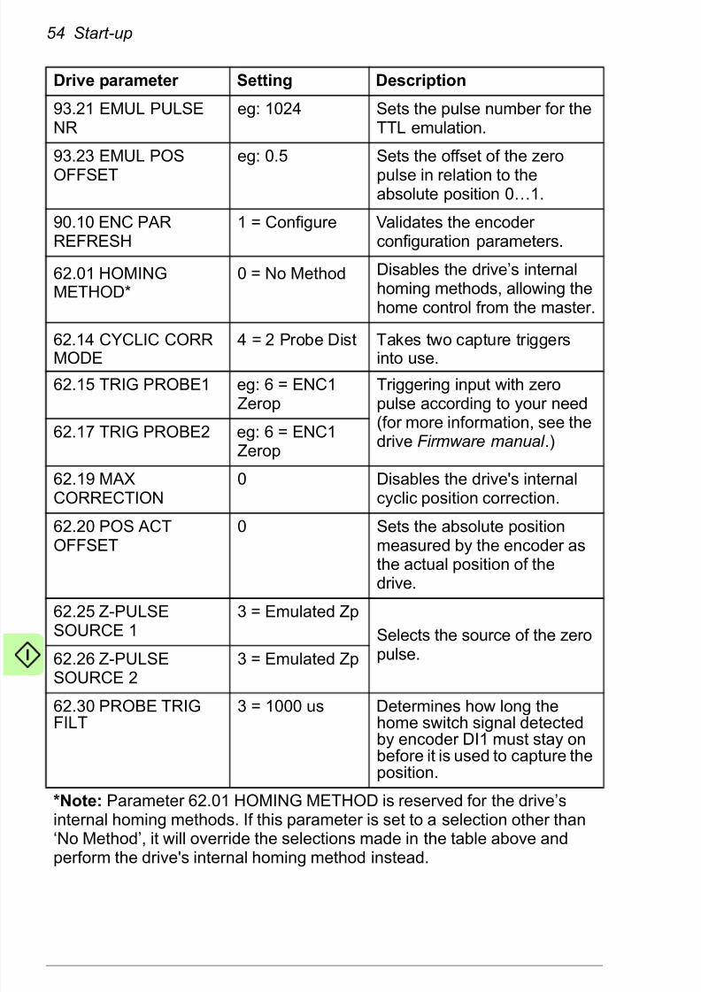
832019 Optic Profibus Manual
httpslidepdfcomreaderfulloptic-profibus-manual 5978
Communication profiles 59
Communication profiles
What this chapter contains
This chapter describes the communication profile used in thecommunication between the MACRO network the adapter module and the drive
Communication profiles
Communication profiles are ways of conveying control commands(Control word Status word References and Actual values)between the master station and the drive
With the FMAC-01 MACRO adapter module the master employsthe MACRO Station profile The profile is converted to the FBAprofile by the adapter module The FBA profile is detailed in thedrive manuals
832019 Optic Profibus Manual
httpslidepdfcomreaderfulloptic-profibus-manual 6078
60 Communication profiles
MACRO Station profile
The MACRO Station profilersquos control and status flags are handledby the adapter module The figure below shows how the controland status flag correlate with the driversquos internal ControlStatus
word
1) FBA CW = xxxx xxxx xxxx xxx0 xxxx 1xx0 1xxx xx01
Start inhibit = 0 Remote Cmd = 1 Reset = 0 Run Enable = 1 Start = 0Stop = 1
2) Flag command Bit 14 Amp enable = 1
3) Flag command Bit 14 Amp enable = 0
4) FBA CW = xxxx xxxx xxxx xxx0 xxxx 1xx0 1xxx xx10Start inhibit = 0 Remote Cmd = 1 Reset = 0 Run Enable = 1 Start = 1Stop = 0
5) FBA SW Bit 6 Ack Start Inhibit = 0
6) Flag status Bit 15 Station Fault = 1
FAULT
OPERATING
IDLE
STARTINHIBITED
Power on
Fault
1)
3) 2)
4)
5)
6)
7)
8)9)
832019 Optic Profibus Manual
httpslidepdfcomreaderfulloptic-profibus-manual 6178
Communication profiles 61
MACRO Station control and status flags
The table below shows the contents the MACRO Station controlflag
7) Flag command Bit 12 Node Reset = 1 -gt FBA CW Bit 8 = 1 (Reset = 1)
8) FBA SW Bit 6 Ack Start Inhibit = 1
9) Flag command Bit 14 Amp enable = 0
Bit Description
23 UserCmdFlg5
22 UserCmdFlg4
21 UserCmdFlg3
20 UserCmdFlg2
19 UserCmdFlg1
18 Reserved
17 Reserved
16 Reserved
15 Station fault (when bit 13 is set to 1)
14 Amplifier Enable
13 This slave detected a MACRO ring break and became aSynchronizing master
12 Node Reset command (Clear faults)
11 Position Capture (Triggered Event) Enable Flag
10 0 indicates a Command Message and not a Status Message
9 Reserved
8 Reserved
7-0 Not available
832019 Optic Profibus Manual
httpslidepdfcomreaderfulloptic-profibus-manual 6278
62 Communication profiles
The table below shows the contents of the MACRO Station statusflag
Bit Description
23 UserStatusFlg5
22 UserStatusFlg4
21 UserStatusFlg3
20 UserStatusFlg2
19 UserStatusFlg1
18 Negative End Limit Flag (NILMn) Input Value
17 Positive End Limit Flag (PILMn) Input Value
16 Home Flag (HMFLn) Input Value
15 Amplifier or Station Node shutdown Fault
14 Amplifier Enabled
13 This Node detected a MACRO Ring Break
12 A Reset has occurred This bit is cleared on the next Amplifier Enable
11 Position Capture (Triggered Event) Occurred Flag10 1 indicates a Status Message and not a Command Message
9 Reserved
8 Reserved
7-0 Not available
832019 Optic Profibus Manual
httpslidepdfcomreaderfulloptic-profibus-manual 6378
Communication protocol 63
Communication protocol
What this chapter contains
This chapter describes the communication on a MACRO network
MACRO protocol
MACRO is an Ethernet-style protocol that uses multi-mode fiber optic (FDDI-PMD ISOIEC 9314-3) or twisted pair copper (CAT5)called 100BASEFX and 100BASETX
MACRO frame structure
Each data packet for a node contains four registers 0 1 2 and 3
bull Register 0 is a 24-bit register for real time data
bull Registers 1 2 and 3 are 16-bit registers for real-time data
Each node has a command packet of four registers and a feedbackpacket of four registers The command and feedback packets slipinto the same data packet for the node (upon entering theaddressed node the data packet is a command packet uponexiting it is a feedback packet)
832019 Optic Profibus Manual
httpslidepdfcomreaderfulloptic-profibus-manual 6478
64 Communication protocol
Services
The MACRO protocol has the ability to pass commands of differenttypes from a controller to a drive Thanks to the high rate of datatransmission over the ring (125 Mbitssec) MACRO facilitates the
closure of high performance servo loops across the ring allowingthe controller and the drive to split the motion control tasksbetween themselves at any level
MACRO specifies services for reading and writing data from thephysical memory within the slaves The FMAC-01 MACRO adapter module supports the following MACRO services
bull Writing and reading drive parameters
bull Axis node MACRO 72-bit cyclic IO format
bull Fast digital output transfer in Control word
bull Home position position capture and over travel limits
bull IO node MACRO 72-bit cyclic IO format
bull Absolute power-on position
bull Flag capture position
bull ASCII transfer commands
Writing and reading drive parameters
Writing parameter values to the drive is performed in two phasesIn the first phase the master writes the group and parameter number to MI30 In the second phase the master writes the data tobe written to MI31 If a writing error occurs the slave returns anerror by setting bit 18 of the node 15 status
Likewise reading parameter values from the drive is performed intwo phases In the first phase the master writes the group andparameter number to MI30 In the second phase the data is readby the master from MI31 If a reading error occurs the slavereturns an error by setting bit 18 of the node 15 status
832019 Optic Profibus Manual
httpslidepdfcomreaderfulloptic-profibus-manual 6578
Communication protocol 65
The table below shows the MI30 bit definitions
The parameter group and index number have to be in hexadecimalformat For example to read parameter 5101
bull Group = 51 decimal = 33 hexadecimal
bull Index = 1 decimal = 1 hexadecimal
bull MI30 = $3301
Axis node MACRO 72-bit cyclic IO format
The 72-bit node cyclic transfer is used to control the drive With theACSM1 drive the command data at the drive is updated at 500microsecond intervals The payload data comprises one 24-bitsegment and three 16-bit segments
The data transferred in axis node communication is selected indrive parameter group 50 by defining the reference control modesand actual values used in the application For typical MACROmotion control applications the parameter settings should be asfollowsbull 5004 FBA REF1 MODESEL = Raw data
bull 5005 FBA REF2 MODESEL = Position
bull 5006 FBA ACT1 TR SRC = P0403 (PROBE1 POS MEAS) or
P0404 (PROBE2 POS MEAS)
Bit Definition
4716 Unused
158 Parameter group number (0hellip255)
70 Parameter index number (0hellip255)
Direction Register 0 (24-bit) 1 (16-bit) 2 (16-bit) 3 (16-bit)
Master toFMAC-01
REF1(Torquevelocity
command)
Unused Unused Flagcommand
FMAC-01 toMaster
ACT2(Positionfeedback)
ACT1(Flag captured position)
Flag status
832019 Optic Profibus Manual
httpslidepdfcomreaderfulloptic-profibus-manual 6678
66 Communication protocol
With these settings the 24-bit MACRO torque command istranslated into the 32-bit drive-internal reference (REF1) The 24-bit MACRO position feedback (MI920) is translated from the 32-bitdrive-internal actual value (ACT2) The MACRO flag capturedposition (MI921) is translated from the 32-bit drive-internal actual
value (ACT1)It is also possible to use alternative settings for the referencecontrol modes Since there is no control mode selection throughthe MACRO variables parameter 5004 FBA REF1 MODESELdetermines how to scale the reference data depending on whatmode is in use Valid modes are torque speed and raw data modeNote that the selected reference control mode also affects thefeedback value transferred in ACT1
bull In the torque mode the maximum MACRO torque command is
scaled to a value of 10000 of the nominal torque The
feedback transferred in ACT1 is the motor torque in percent of
the motor nominal torque
bull In the speed mode the scaling is determined by parameter
2502 SPEED SCALING The feedback transferred in ACT1 is
the filtered actual speed in rpm
bull In the raw data mode the scaling is determined by theFMAC-01 configuration parameter 21 RAW REFERENCE
SCALE The feedback transferred in ACT1 is selected with
parameter 5006 FBA ACT1 TR SRC
Even though reference 2 is not used in axis node communicationparameter 5005 FBA REF2 MODESEL defines the feedbacktransferred in ACT2 from the drive to the master With the MACROinterface this parameter should always be set to lsquoPositionrsquo This
setting transfers the drives actual position as feedback in ACT2The scaling of the position feedback is determined by the FMAC-01 configuration parameter 22 CYCLIC POSITION FEEDBACKFORMAT However the most significant 8 bits of the drives ACT2are always discarded
The actual drive control mode is selected with drive parameters3401 EXT1EXT2 SEL 3402 EXT1 MODE 12 SEL 3403 EXT1CTRL MODE1 and 3404 EXT1 CTRL MODE2 For further information see the drive Firmware manual and the parameter setting examples in section Starting up the ACSM1 drive on page47
832019 Optic Profibus Manual
httpslidepdfcomreaderfulloptic-profibus-manual 6778
Communication protocol 67
Fast digital output transfer in Control word
Four freely programmable bits in the FBA MAIN CW can be usedto transfer fast digital outputs as follows
To use the freely programmable bits from the FBA MAIN CW in thedrive bits 28 29 30 or 31 of parameter 0212 FBA MAIN CW haveto be mapped to the bit in the parameter to be controlled
Example To map bit 28 of the FBA MAIN CW to the first digitaloutput (DIO1) set parameter 1204 DIO1 OUT PTR to P021228(0212 FBA MAIN CW bit 28)
Home position position capture and overtravel
limits
The MACRO flag status bits are mapped to the drive FBA MAINSW as shown in the table below
Digitaloutput 1
Digitaloutput 2
Digitaloutput 3
Digitaloutput 4
FBAMAIN CW
CW B28 CW B29 CW B30 CW B31
MACROFlagcommand
B19 -UserCmdFlg1
B20 -UserCmdFlg2
B21 -UserCmdFlg3
B22 -UserCmdFlg4
Homeposition
Positiveover travel
Negativeover travel
Positioncapture
FBA MAIN SW SW B28 SW B29 SW B30 SW B31
MACRO Flagstatus
B16 - HomeFlag
(HMFLn)Input Value
B17 -Positive
End LimitFlag
(PILMn)Input Value
B18 -NegativeEnd Limit
Flag(NILMn)
Input Value
B11 -Position
Captured(Triggered
EventOccurred)
Flag
832019 Optic Profibus Manual
httpslidepdfcomreaderfulloptic-profibus-manual 6878
68 Communication protocol
The captured position will be sent from the drive to the adapter module using ACT1 For this to work an appropriate driveparameter has to be mapped to parameter 5006 FBA ACT1 TRSRC For the mapping parameter 5004 FBA REF1 MODESELhas to be set to lsquoRaw datarsquo See the parameter setting examples in
section Starting up the ACSM1 drive on page 47
IO node MACRO 72-bit cyclic IO format
The 72-bit node cyclic transfer is used to transfer parameter-mapped data to and from the drive (parameter groups 52 and 53)Low priority cyclic data is updated at 2 ms intervals The payloaddata comprises one 24-bit segment and three 16-bit segments
If the actual data is smaller than the payload segment the data isplaced in the least significant byte(s)
Absolute power-on position
MI-variable MI920 contains the drives actual position read fromdrive parameter 0112 POS ACT The position value of the drive isshown in MACRO format in MI920
Flag capture position
MI-variable MI921 contains the latest captured position value
DirectionRegister
0 (24-bit) 1 (16-bit) 2 (16-bit) 3 (16-bit)
Master toFMAC-01
5301 FBADATA OUT1
5302 FBADATA OUT2
5303 FBADATA OUT3
5304 FBADATA OUT4
FMAC-01 toMaster
5201 FBADATA IN1
5202 FBADATA IN2
5203 FBADATA IN3
5204 FBADATA IN4
832019 Optic Profibus Manual
httpslidepdfcomreaderfulloptic-profibus-manual 6978
Communication protocol 69
ASCII transfer commands
Node 14 is used to transfer 48-bit ASCII commands from themaster These commands are transmitted using the broadcastfeature of the MACRO protocol
The table below lists all ASCII commands supported by FMAC-01
ASCII command Explanation Type
MACSTAx Initiates ASCII communicationbetween the master station andthe selected slave station x
Reports the MACRO StationGlobal Status register (MI4)
Unsigned 32-bitinteger
$$$ Resets the MACRO station andrestores all station MI-variablesto their last saved values
$$$ Resets the MACRO station andrestores all station MI-variablesto their factory default values
BKUP Reports all saved MI-variables ASCII string
CID Reports the MACRO stationrsquospart number (CardID) Unsigned 32-bitinteger
CLRF Clears all faults on the MACROstation and prepares it for further operation
DATE Reports the date of the firmware MonthDayYear
SAVE Copies the MACRO stationrsquosMI-variable values from the
volatile active memory to thenon-volatile flash memory
SID Reports the serial number of theMACRO station
Unsigned 32-bitinteger
TYPE Reports the MACRO station type(ldquouMacrordquo)
ASCII string
VERS Reports the firmware versionnumber
0001 9999(BCD)
832019 Optic Profibus Manual
httpslidepdfcomreaderfulloptic-profibus-manual 7078
70 Communication protocol
Ring order set-up
Upon the initial binding of a MACRO station to a MACRO masterthe ring order set-up is used if FMAC-01 configuration parameter 06 (STATION ORDER NUMBER) is set to 0 Otherwise parameter 03 (SW1) or parameters 04 05 and 06 (MASTER ADDRESSAXIS NODE ADDRESS and IO NODE ADDRESS) are used to setup the axis and IO nodes and the master
In the ring order set-up the ring controller sends out a commandon the ring in the ASCII communication protocol asking to talk tothe first MACRO station that does not have a station number Oncethe communication is established the ring controller can define theMACRO binding of the slave station to a master and their bindingnode(s)
Timing and synchronization
The timing of the reference and actual position feedback isimportant in a MACRO network The rate at which referencesshould be fed and position feedback read is determined by theservo clock rate (which is determined by the phase clock and servoclock divider set by MI990) The servo clock has to be set to 2 kHzThis value corresponds to the hexadecimal value 0x13880444 of MI990
In some applications it may be beneficial that all drives in the ringare internally synchronized with each other To start thesynchronization send an ldquomsyncrdquo command from the MACROmaster
VID Reports the MACRO stationrsquosvendor identification number (6 ABB)
ASCII string
ASCII command Explanation Type
832019 Optic Profibus Manual
httpslidepdfcomreaderfulloptic-profibus-manual 7178
Communication protocol 71
Acyclic and cyclic communication modes
The FMAC-01 MACRO adapter module supports the Type 1MACRO protocol One axis node and one IO node are supportedThe addresses available to the axis node are 0 1 4 5 8 9 12 or
13 to the IO node 2 3 6 7 10 or 11Nodes 14 and 15 are used for acyclic communication Node 14 isused for 48-bit broadcast ASCII transfer Node 15 is used by themaster to readwrite the MI-variables
MI-variables supported by FMAC-01
MI-variable Name RORW FMAC-01configurationparameter (group 51)
MI0 Station Firmware Version RO 10
MI1 Station Firmware Date RO
MI2 Station ID and User Configuration Word
RW 11 12
MI3 SW1 and SW2 RW 03 04
MI4 Station Status Word RO 13MI5 Ring Error Counter RW 18 19
MI8 MACRO Ring CheckPeriod
RW 14
MI9 MACRO Ring Error Shutdown Count
RW 15
MI10 MACRO Sync Packet
Shutdown Count
RW 16
MI11 Station Order Number RW 09
MI12 Card Identification RO
MI20 Cyclic PositionFeedback Format
RW 22
MI30 Drive parameter groupindex
RW
MI31 Drive parameter data RW
832019 Optic Profibus Manual
httpslidepdfcomreaderfulloptic-profibus-manual 7278
72 Communication protocol
MI920 Absolute Power-On
Position
RO 22
MI921 Flag Capture Position RO 22
MI990 Clock Control Register RW 19 20
MI992 MaxPhase FrequencyControl
RW 19 20
MI993 Servo Encoder ClockDivisor
RW 19 20
MI994 Flag Clock Divisor RW 19 20MI995 MACRO Ring
ConfigurationStatusRW 17
MI996 MACRO Node ActivateControl
RW 03 04 05 06 07 08
MI998 Servo Clock FrequencyControl
RW
MI-variable Name RORW FMAC-01configurationparameter (group 51)
832019 Optic Profibus Manual
httpslidepdfcomreaderfulloptic-profibus-manual 7378
Diagnostics 73
Diagnostics
What this chapter contains
This chapter explains how to trace faults with the status LEDs onthe adapter module
LED indications
The adapter module is equipped with three bicolor diagnosticLEDs The LEDs are described below
Name Color Function
HOST
Blinking green Establishing communication tohost
Green Connection to host OKBlinking red Communication to host lost
temporarily
832019 Optic Profibus Manual
httpslidepdfcomreaderfulloptic-profibus-manual 7478
74 Diagnostics
A station fault is triggered if
bull a ring break occurs
bull the number of ring communication errors exceeds the MACRO
ring error shutdown count defined by par 15 (MI9)
bull the number of sync packets falls short of the MACRO sync
packet shutdown count defined by par 16 (MI10) during the
check period defined by par 14 (MI8)
bull another station is on the same node number
For the descriptions of the FMAC-01 configuration parametersabove see page 39
MODULE
Off (dark) Configuration not done Nonodes selected to be active
Green Ring active no faults
Blinking green Module in ASCII mode
Red Ring break detected
Blinking red Station fault or drive fault
NET Green MACRO link OK
Red MACRO link down
Name Color Function
832019 Optic Profibus Manual
httpslidepdfcomreaderfulloptic-profibus-manual 7578
Technical data 75
Technical data
What this chapter contains
This chapter contains the technical data of the adapter module andthe MACRO link
FMAC-01
The figure below shows the enclosure of the adapter module fromthe front and side
832019 Optic Profibus Manual
httpslidepdfcomreaderfulloptic-profibus-manual 7678
76 Technical data
MACRO link
Mounting Into the option slot of the drive
Degree of protection IP20
Ambient conditions The applicable ambient conditions specified for the drive in its manuals are in effect
Indicators Three bicolor LEDs (HOST MODULE NET)
Connectors 20-pin connector to the drive (X3)
Two SC fiber optic connectors (X1 and X2)
Power supply +33 V plusmn 5 max 450 mA (supplied by the drive)
General Estimated min lifetime 100 000 h
All materials ULCSA-approved
Complies with EMC standard EN 61800-32004
Medium Fiber optic
bull Wiring FDDI-PMD ISOIEC 9314-3
bull Connector SC
bull Maximum segment length 3000 m
Topology Ring
Transfer rate Up to 125 Mbits
Serial communicationtype
Full duplex
Protocol MACRO
832019 Optic Profibus Manual
httpslidepdfcomreaderfulloptic-profibus-manual 7778
Further information
Product and service inquiries
Address any inquiries about the product to your local ABBrepresentative quoting the type designation and serial number of
the unit in question A listing of ABB sales support and service
contacts can be found by navigating to wwwabbcomdrives and
selecting Sales Support and Service network
Product training
For information on ABB product training navigate to wwwabbcomdrives and select Training courses
Providing feedback on ABB Drives manuals
Your comments on our manuals are welcome Go to
wwwabbcomdrives and select Document Library ndash Manuals
feedback form (LV AC drives)
Document library on the Internet
You can find manuals and other product documents in PDF format
on the Internet Go to wwwabbcomdrives and select Document
Library You can browse the library or enter selection criteria for
example a document code in the search field
832019 Optic Profibus Manual
httpslidepdfcomreaderfulloptic-profibus-manual 7878
Contact us
ABB Oy
DrivesPO Box 184FI-00381 HELSINKIFINLANDTelephone +358 10 22 11Fax +358 10 22 22681wwwabbcomdrives
ABB Inc
Automation TechnologiesDrives amp Motors16250 West Glendale DriveNew Berlin WI 53151USATelephone 262 785-3200
1-800-HELP-365Fax 262 780-5135wwwabbcomdrives
ABB Beijing Drive Systems
Co LtdNo 1 Block DA-10 Jiuxianqiao BeiluChaoyang DistrictBeijing PR China 100015Telephone +86 10 5821 7788Fax +86 10 5821 7618wwwabbcomdrives
3
A U A 0 0 0 0 0 8 9 4 3 1 R e v A
( E N ) 2 0 1 0 - 1 2 - 0 3
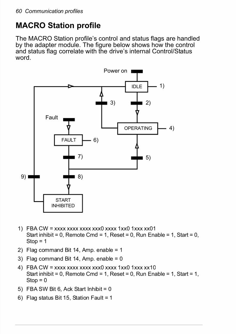
832019 Optic Profibus Manual
httpslidepdfcomreaderfulloptic-profibus-manual 7878
Contact us
ABB Oy
DrivesPO Box 184FI-00381 HELSINKIFINLANDTelephone +358 10 22 11Fax +358 10 22 22681wwwabbcomdrives
ABB Inc
Automation TechnologiesDrives amp Motors16250 West Glendale DriveNew Berlin WI 53151USATelephone 262 785-3200
1-800-HELP-365Fax 262 780-5135wwwabbcomdrives
ABB Beijing Drive Systems
Co LtdNo 1 Block DA-10 Jiuxianqiao BeiluChaoyang DistrictBeijing PR China 100015Telephone +86 10 5821 7788Fax +86 10 5821 7618wwwabbcomdrives
3
A U A 0 0 0 0 0 8 9 4 3 1 R e v A
( E N ) 2 0 1 0 - 1 2 - 0 3