Embed Size (px)
Citation preview
OPTIc Page 2
Version: E-2005-05-13 Page 2
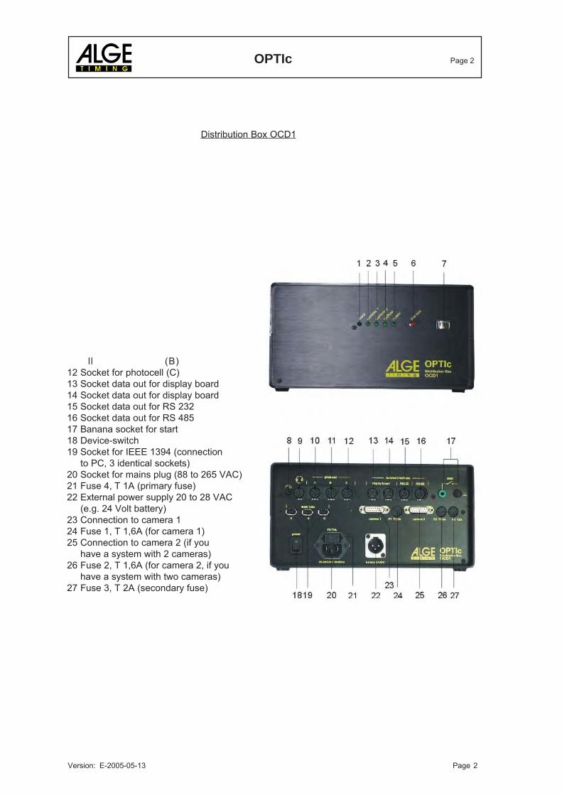
Distribution Box OCD1
ll (B)12 Socket for photocell (C)13 Socket data out for display board14 Socket data out for display board15 Socket data out for RS 23216 Socket data out for RS 48517 Banana socket for start18 Device-switch19 Socket for IEEE 1394 (connection
to PC, 3 identical sockets)20 Socket for mains plug (88 to 265 VAC)21 Fuse 4, T 1A (primary fuse)22 External power supply 20 to 28 VAC
(e.g. 24 Volt battery)23 Connection to camera 124 Fuse 1, T 1,6A (for camera 1)25 Connection to camera 2 (if you
have a system with 2 cameras)26 Fuse 2, T 1,6A (for camera 2, if you
have a system with two cameras)27 Fuse 3, T 2A (secondary fuse)
OPTIc Page 3
Version: E-2005-05-13 Page 3
Table of Contents1. INTRODUCTION ............................................................................................................................... 41.1. System Components .......................................................................................................................... 41.2. Functions ........................................................................................................................................... 51.3. System Components and its Functions .............................................................................................. 61.4. Sports that Require a Photofinish System.......................................................................................... 62. INSTALLATION OF THE OPTIc......................................................................................................... 72.1. Power Supply ..................................................................................................................................... 72.2. Installing the PCI-Card IEEE 1394 into your PC ................................................................................ 72.3. Installing the Software for Windows NT/2000 .................................................................................... 72.3.1. Installing the IEEE 1394 drover .......................................................................................................... 82.4. Installing the software for Windows 2000 (OHCI-IEEE 1394 card) .................................................. 102.4.1. Installing the OPTI device driver ...................................................................................................... 102.4.2.2. Test the PCI-card IEEE 1394 (OHCI) ............................................................................................... 122.3.3. Installation of the OPTIc-Software ................................................................................................... 122.3.4. Test Pictures .................................................................................................................................... 132.3.5. Software for White Balance .............................................................................................................. 132.4. Cabling of the System ...................................................................................................................... 143. COMPONENTS OF THE OPTIc SYSTEM ...................................................................................... 153.1. Line Scan Camera OCC1 ................................................................................................................ 153.2. Distribution Box OCD1 ..................................................................................................................... 184. ADJUSTMENT OF THE LINE SCAN CAMERA OCC1 ................................................................... 194.1. Adjustment of the White Balance of the Camera: ............................................................................ 234.2. Test start – An easy way for the Referee to check the System: ....................................................... 244.3. Anemometer for Athletic: .................................................................................................................. 255. SOFTWARE ..................................................................................................................................... 265.1. Menus of the Software: .................................................................................................................... 275.1.1. Menu <FILE>: .................................................................................................................................. 275.1.2. Menu < RACE >: .............................................................................................................................. 275.1.3. Menu < WORK >: ............................................................................................................................. 285.1.4. Menu < IMAGE EVALUATION >: ..................................................................................................... 285.1.5. Menu < IMAGE >: ............................................................................................................................ 295.1.6. Menu < SYSTEM >: ......................................................................................................................... 305.1.7. Menu < SHOW > .............................................................................................................................. 325.1.8. Menu < WINDOW > ......................................................................................................................... 326. CARRYING OUT OF A RACE.......................................................................................................... 337. EVALUATION ................................................................................................................................... 347.1. Showing the Time-Line on the screen .............................................................................................. 347.2. Time Window ................................................................................................................................... 347.3. Transfer times into the competitor list .............................................................................................. 347.3.1. Manual Identification ........................................................................................................................ 347.3.2. Lane Identification ............................................................................................................................ 357.3.3. Start Number Identification ............................................................................................................... 367.4. Competitor list .................................................................................................................................. 378. OPTIc OPTIONS .............................................................................................................................. 398.1. Startmicrophone SM8, Speech Amplifier SV4/SM and Headset Q34: ............................................. 398.2. Photocell: ......................................................................................................................................... 418.2.1. Photocell RLS1n: ............................................................................................................................. 418.2.2. Three-Fold-Photocell ....................................................................................................................... 438.3. Display Board GAZ4 WS3 to show the wind speed: ........................................................................ 449. TECHNICAL DATA ........................................................................................................................... 4510. ADDITION ........................................................................................................................................ 4910.1. Working with the registry: ................................................................................................................. 4910.2. Excel Import and Export functions from OPTIc Version 3.5: ............................................................ 50
As defined by the progress we subject to change the state of technology.You can download the newest table of contents from our homepage www.alge-timing.comfor free. OPTIc manual copyright by: ALGE-TIMINGALGE-TIMINGALGE-TIMINGALGE-TIMINGALGE-TIMING, Rotkreuzstraße 39, A-6890 Lustenau
OPTIc Page 4
Version: E-2005-05-13 Page 4
1. INTRODUCTION
1.1. System Components
PC requirements:
Intel Pentium III resp. Athlon or faster.Windws 2000 Service Pack 2 or Windows NT (Service Pack 3 or higher)128 MB RAMHard disk with min. 10 GB (the more hard disk space, the longer the recording time)CD-driveKeyboard for PCMouse for PCGraphic card X-VGA (min. 8 MB RAM)Monitor with min. 1024 x 768 resolution and true colorfree PCI slot for IEEE 1394 interface or integrated IEEE 1394 interfaceColor printer to print the pictures and result lists (color laser or ink jet printer)
The OPTIc includes the following parts:
Color Line Scan Camera OCC1OPTI Distribution Box OCD1PCI Board with IEEE 1394 interfaceZoom Objective 12,5 -75 mm (C-Mount)Adapter for C-Mount objectiveTelescopic Sight with cross hair on cameraOPTIc Software for Windows 95B resp. Windows NTCamera cable 10 mCable for IEEE 1394Start-Stop-Simulator-Adapter 087—5
Options for the OPTIc:
Startmicrophone SM8Speech Amplifier SV4/SM2 x Headset Q34Photocell RLS1n (reach: 1 to 25 m)Photocell RLS1nd (reach: up to 150 m)Three-Fold-Photocell RLS3c with tripodHandswitch 020-02Display Board GAZ4Cable Reel KT 300Motor Zoom 16 - 160 mm / F1,8 - 1400, controlled by PC (focus, zoom and iris)Weather shield for cameraAdditional second Line Scan Camera OCC1 (starting in autumn 2000)Viewer + Optic (Nikon Bayonet)Camera tripod for OPTIAnemometer Windmaster 2000+Cable Reel with 60 m cable for AnemometerAdapter for Nikon Objective lensesWindspeed on Display Board (WSGA)Tripod with decline
OPTIc Page 5
Version: E-2005-05-13 Page 5
1.2. Functions
The ALGE OPTIc system is an electronic photo timing system with integrated evaluation software.High timing precision is guaranteed by a temperature compensated quartz oscillator (TCXO). TheOPTIc works with a PC under Windows NT and Windows 95B . The system is very easy to operatedue to the Windows surface.
The Line Scan Camera (CCD image sensor) scans every movement on the finish line and recordsit on the hard disk of the PC. It is possible to scan up to 2000 lines per second.
A few seconds after you recorded a finish arrival it shows the picture on the monitor of thecomputer. You can read the times from the picture up to precision of 1/2000 seconds. Each timewill be integrated immediately into the evaluation software. For close finish arrivals you have azoom function.
The following example will show you how a picture is recorded. If you use a scan rate of 1/1000seconds it means that the finish line will be scanned 1000 times per second.
The next example shows the same object, but now crossing the finish line with a slower speed andsame scan rate of 1/1000. The shape of the recorded picture will depend on the speed of thepicture and scan rate. Therefore it is very important to record with the correct scan rate to get therealistic shape of the picture. The picture below shows that object stretched, if using the same scanrate at a slower speed. Of course the object will be scanned more often under such circumstances.
For the ALGE OPTIc you do not need to develop pictures thank to the modern digital system. Thiswill help you save money (film and development costs) and avoids the use of chemicals. Therecorded picture is stored on the hard disk (bitmap format) thus making it possible to print it at anytime with a printer.
OPTIc Page 6
Version: E-2005-05-13 Page 6
1.3. System Components and its Functions
Personal Computer (PC):PC to control, evaluate and store the pictures.
S-VGA Color Monitor:Monitor with min. 17” and XGA resolution (1024 x 768 pixel).
Keyboard:To operate the PC
Mouse:To operate the PC
PCI-Board with IEEE 1394 Interface:To transfer the pictures in real time into the PC you need a fast data transmission. TheIEEE 1394 (Firewire®) is a very fast and future orientated interface. The data transfer ratereaches at the moment up to 400 Mbit/s.
OPTI Distribution Box OCD1:The OCD1 is a high precision timer (with TCXO quartz oscillator). In the OCD1 it mixes thepictures with its time. Further you can connect all external timing devices at the OCD1 (e.g.Startmicrophone, Photocell, Display Board).The OCD1 also has an integrated power supply (88 – 265 V / 50 – 60 Hz / 60 W) whichsupplys the OCD1, camera, photocell, etc.
OPTI Line Scan Camera OCC1:Color line scan camera (3-line sensor with RGB) that allows you to scan the finish line upto 2000 times per second. Supported resolutions are under Windows NT: 1365, 1024, 768and 625 pixel (High resoluton 1356 Pixel). The camera is connected with the OCD1 with the 10 m
standard cable (alternative up to 100 m cable) that is supplied by the OCC1.
Objective for the Camera: standard lens supplied is a zoom objective 12.5 – 75 mm, 1 : 1.2 (C-Mount).If needed it is also possible to use other fix as zoom objective lenses. ALGE supplies anadapter for Nikon objectives. Alternatively ALGE also supplies a Motor Zoom 16 - 160 mm/ F1,8 – 1400 with remote control from the PC (focus, zoom and iris).
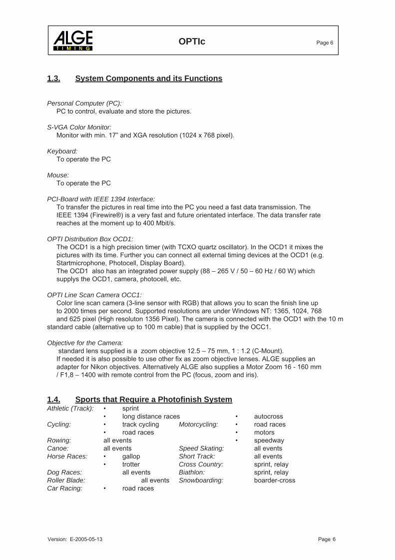
1.4. Sports that Require a Photofinish SystemAthletic (Track): • sprint
• long distance races • autocrossCycling: • track cycling Motorcycling: • road races
• road races • motorsRowing: all events • speedwayCanoe: all events Speed Skating: all eventsHorse Races: • gallop Short Track: all events
• trotter Cross Country: sprint, relayDog Races: all events Biathlon: sprint, relayRoller Blade: all events Snowboarding: boarder-crossCar Racing: • road races
OPTIc Page 7
Version: E-2005-05-13 Page 7
2. INSTALLATION OF THE OPTIc
2.1. Power Supply
PC, Monitor and Printer:
For the power supply. Read the handbook of PC, monitor, and printer. On request ALGE can alsodeliver a USP (emergency power supply) for the complete system (except printer).
OPTI Distribution Box OCD1:
A power supply (105 to 230 V / 50 to 60 Hz) is installed in the OCD1. This supplies the OCD1, thecamera, and perepherial devices. If you use a USP it is necessary to supply the OCD1 from theUSP.
2.2. Installing the PCI-Card IEEE 1394 into your PC
The PCI card must be installed in your computer by your computer dealer or by your ALGErepresentative.ALGE has now surrounded to the new IEEE 1394 (OHCI) standard. This standard will be assistedfrom the new operating system (Windows 2000, Windows 98, Windows ME).Some PC's (especially laptops) have already mounted this interface.We recommend the operation system Windows 2000 because this one is very solid.
- Switch the PC off- Take the case cover of the PC off, so you can see the PCI sockets.- Remove the cover of the PCI card that you want to use.- Plug the card in the PCI slot.- Screw the PCI card to the case.- Put the case cover back on the PC.- Switch the PC on.- Continue like descibed on 2.4 resp. 2.5
2.3. Installing the Software for Windows NT/2000
If you want install Windows NT you must prepare the hardware for Windows NT. You need theright IEEE 1394 card and also the camera and the Distribution-Box have to be prepared for theoperating system.
Camera OCC1: Please check if the camera has a sign on the bottom for a high resolution quality.
Distribution-Box OCD1: Please check if the distribution-box has a sign on the bottom that it iscompatible with Windows NT.
OPTIc Page 8
Version: E-2005-05-13 Page 8
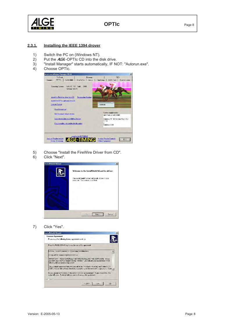
2.3.1. Installing the IEEE 1394 drover
1) Switch the PC on (Windows NT).2) Put the ALGE-OPTIc CD into the disk drive.3) "Install Manager" starts automatically, IF NOT: "Autorun.exe".4) Choose OPTIc.
5) Choose "Install the FireWire Driver from CD".6) Click "Next".
7) Click "Yes".
OPTIc Page 9
Version: E-2005-05-13 Page 9
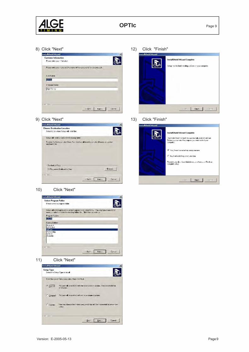
8) Click "Next" 12) Click "Finish"
9) Click "Next" 13) Click "Finish"
10) Click "Next"
11) Click "Next"

OPTIc Page 10
Version: E-2005-05-13 Page 10
2.4. Installing the software for Windows 2000 (OHCI-IEEE 1394 card)
If you want install Windows 2000 the hardware will have to be prepared for it.An OHCI compatible card must be mounted.
Camera OCC1: Please check if there is a tip on the bottom of the camera that the camera is highresolution.
Distribution Box OCD1: Please check if there is a tip on the bottom of the distribution box that thedistribution box is compatible with Windows 2000/NT.
While starting the operting system the driver will be installed automatically.
2.4.1. Installing the OPTI device driver
1) Start the PC (Windows 2000)2) Put the ALGE OPTI-c CD into the disk drive.3) "Install Manager" start s automatically; IF NOT: "Autorun.exe"4) Choose OPTIc5) Install the OPTIc software (see chapter 2.4.3.). The driver will be installed automatically into the
program directory (presetting: c:\programme\optic-ohci)6) Put in the distribution box and switch on. The operating system knows automatically that a new
device is connected to the IEEE 1394 interface and it will ask for a suitable device driver. Givenow the program directory where the driver is.
7) Click on "Next"
8) Click on "Next" 9) Click on "Next"
OPTIc Page 11
Version: E-2005-05-13 Page 11
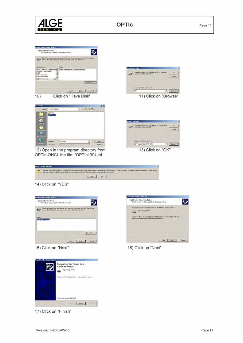
10) Click on "Have Disk" 11) Click on "Browse"
12) Open in the program directory from 13) Click on "OK"OPTIc-OHCI the file: "OPTIc1394.inf.
14) Click on "YES"
15) Click on "Next" 16) Click on "Next"
17) Click on "Finish"
OPTIc Page 12
Version: E-2005-05-13 Page 12
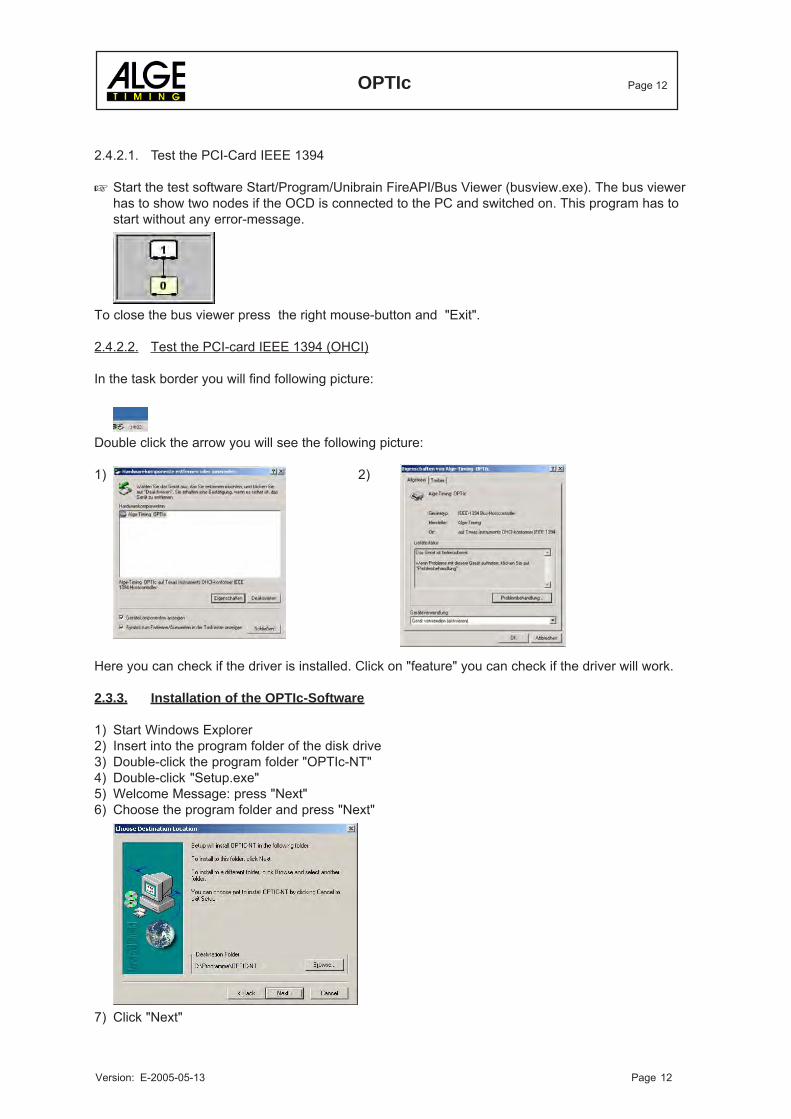
2.4.2.1. Test the PCI-Card IEEE 1394
Start the test software Start/Program/Unibrain FireAPI/Bus Viewer (busview.exe). The bus viewerhas to show two nodes if the OCD is connected to the PC and switched on. This program has tostart without any error-message.
To close the bus viewer press the right mouse-button and "Exit".
2.4.2.2. Test the PCI-card IEEE 1394 (OHCI)
In the task border you will find following picture:
Double click the arrow you will see the following picture:
1) 2)
Here you can check if the driver is installed. Click on "feature" you can check if the driver will work.
2.3.3. Installation of the OPTIc-Software
1) Start Windows Explorer2) Insert into the program folder of the disk drive3) Double-click the program folder "OPTIc-NT"4) Double-click "Setup.exe"5) Welcome Message: press "Next"6) Choose the program folder and press "Next"
7) Click "Next"
OPTIc Page 13
Version: E-2005-05-13 Page 13
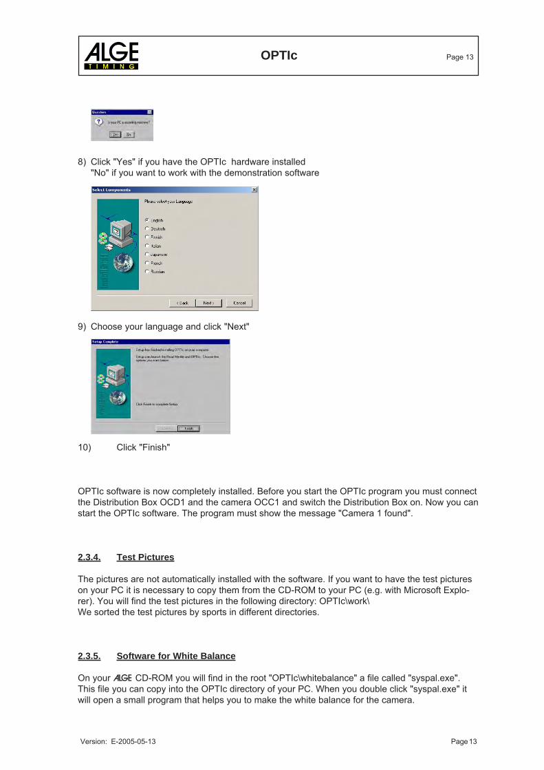
8) Click "Yes" if you have the OPTIc hardware installed"No" if you want to work with the demonstration software
9) Choose your language and click "Next"
10) Click "Finish"
OPTIc software is now completely installed. Before you start the OPTIc program you must connectthe Distribution Box OCD1 and the camera OCC1 and switch the Distribution Box on. Now you canstart the OPTIc software. The program must show the message "Camera 1 found".
2.3.4. Test Pictures
The pictures are not automatically installed with the software. If you want to have the test pictureson your PC it is necessary to copy them from the CD-ROM to your PC (e.g. with Microsoft Explo-rer). You will find the test pictures in the following directory: OPTIc\work\We sorted the test pictures by sports in different directories.
2.3.5. Software for White Balance
On your ALGE CD-ROM you will find in the root "OPTIc\whitebalance" a file called "syspal.exe".This file you can copy into the OPTIc directory of your PC. When you double click "syspal.exe" itwill open a small program that helps you to make the white balance for the camera.
OPTIc Page 14
Version: E-2005-05-13 Page 14
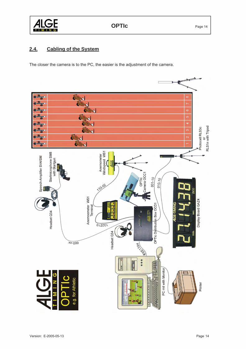
2.4. Cabling of the System
The closer the camera is to the PC, the easier is the adjustment of the camera.
OPTIc Page 15
Version: E-2005-05-13 Page 15
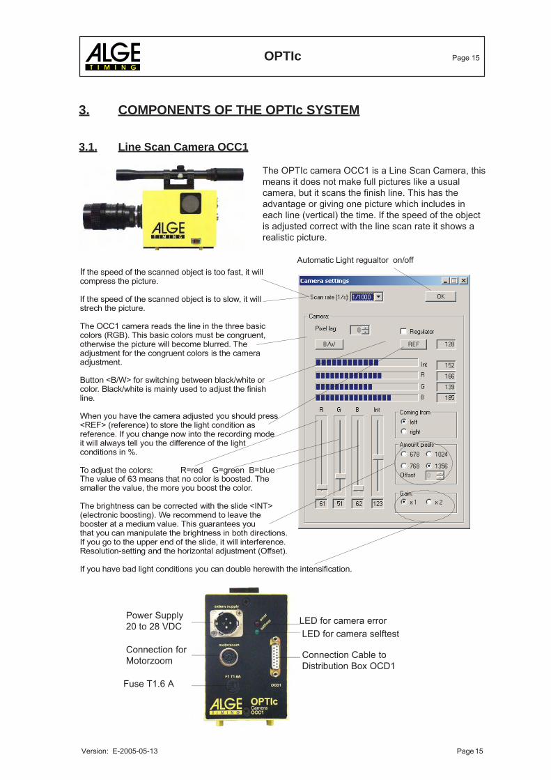
Power Supply20 to 28 VDC
Connection forMotorzoom
Fuse T1.6 A
LED for camera error
Connection Cable toDistribution Box OCD1
LED for camera selftest
3. COMPONENTS OF THE OPTIc SYSTEM
3.1. Line Scan Camera OCC1
The OPTIc camera OCC1 is a Line Scan Camera, thismeans it does not make full pictures like a usualcamera, but it scans the finish line. This has theadvantage or giving one picture which includes ineach line (vertical) the time. If the speed of the objectis adjusted correct with the line scan rate it shows arealistic picture.
If the speed of the scanned object is too fast, it willcompress the picture.
If the speed of the scanned object is to slow, it willstrech the picture.
The OCC1 camera reads the line in the three basic colors (RGB). This basic colors must be congruent,otherwise the picture will become blurred. The adjustment for the congruent colors is the cameraadjustment.
Button <B/W> for switching between black/white orcolor. Black/white is mainly used to adjust the finishline.
When you have the camera adjusted you should press<REF> (reference) to store the light condition asreference. If you change now into the recording modeit will always tell you the difference of the lightconditions in %.
To adjust the colors: R=red G=green B=blueThe value of 63 means that no color is boosted. The smaller the value, the more you boost the color.
The brightness can be corrected with the slide <INT>(electronic boosting). We recommend to leave thebooster at a medium value. This guarantees youthat you can manipulate the brightness in both directions. If you go to the upper end of the slide, it will interference.Resolution-setting and the horizontal adjustment (Offset).
If you have bad light conditions you can double herewith the intensification.
Automatic Light regualtor on/off
OPTIc Page 16
Version: E-2005-05-13 Page 16
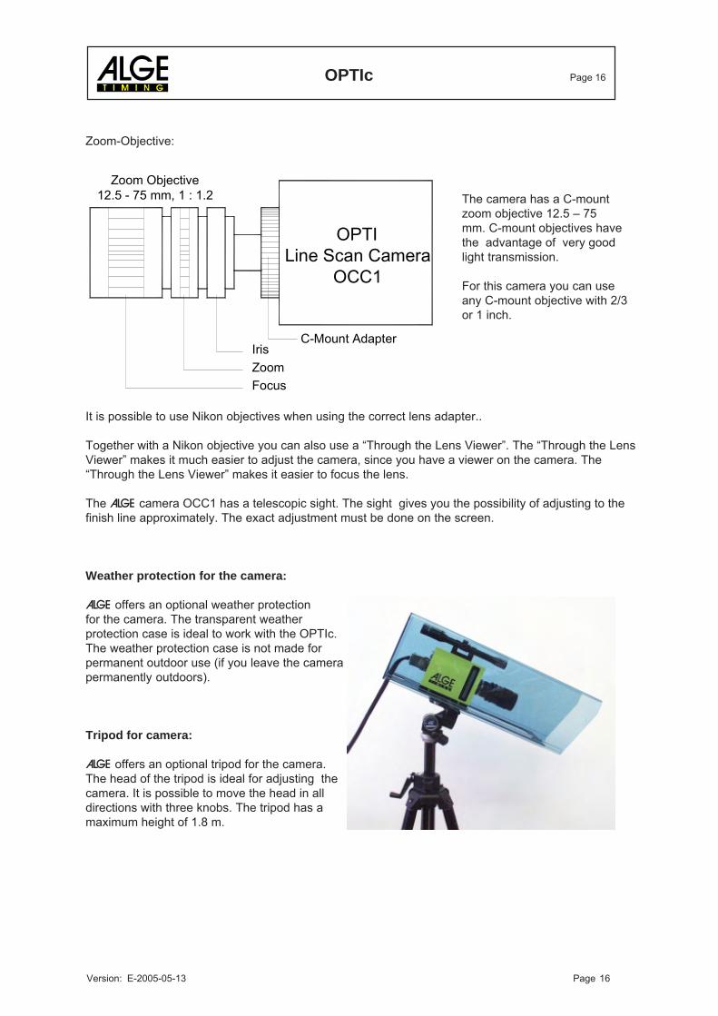
IrisZoomFocus
OPTI Line Scan Camera
OCC1
Zoom Objective12.5 - 75 mm, 1 : 1.2
C-Mount Adapter
Zoom-Objective:
The camera has a C-mountzoom objective 12.5 – 75mm. C-mount objectives havethe advantage of very goodlight transmission.
For this camera you can useany C-mount objective with 2/3or 1 inch.
It is possible to use Nikon objectives when using the correct lens adapter..
Together with a Nikon objective you can also use a “Through the Lens Viewer”. The “Through the LensViewer” makes it much easier to adjust the camera, since you have a viewer on the camera. The“Through the Lens Viewer” makes it easier to focus the lens.
The ALGE camera OCC1 has a telescopic sight. The sight gives you the possibility of adjusting to thefinish line approximately. The exact adjustment must be done on the screen.
Weather protection for the camera:
ALGE offers an optional weather protectionfor the camera. The transparent weatherprotection case is ideal to work with the OPTIc.The weather protection case is not made forpermanent outdoor use (if you leave the camerapermanently outdoors).
Tripod for camera:
ALGE offers an optional tripod for the camera.The head of the tripod is ideal for adjusting thecamera. It is possible to move the head in alldirections with three knobs. The tripod has amaximum height of 1.8 m.
OPTIc Page 17
Version: E-2005-05-13 Page 17
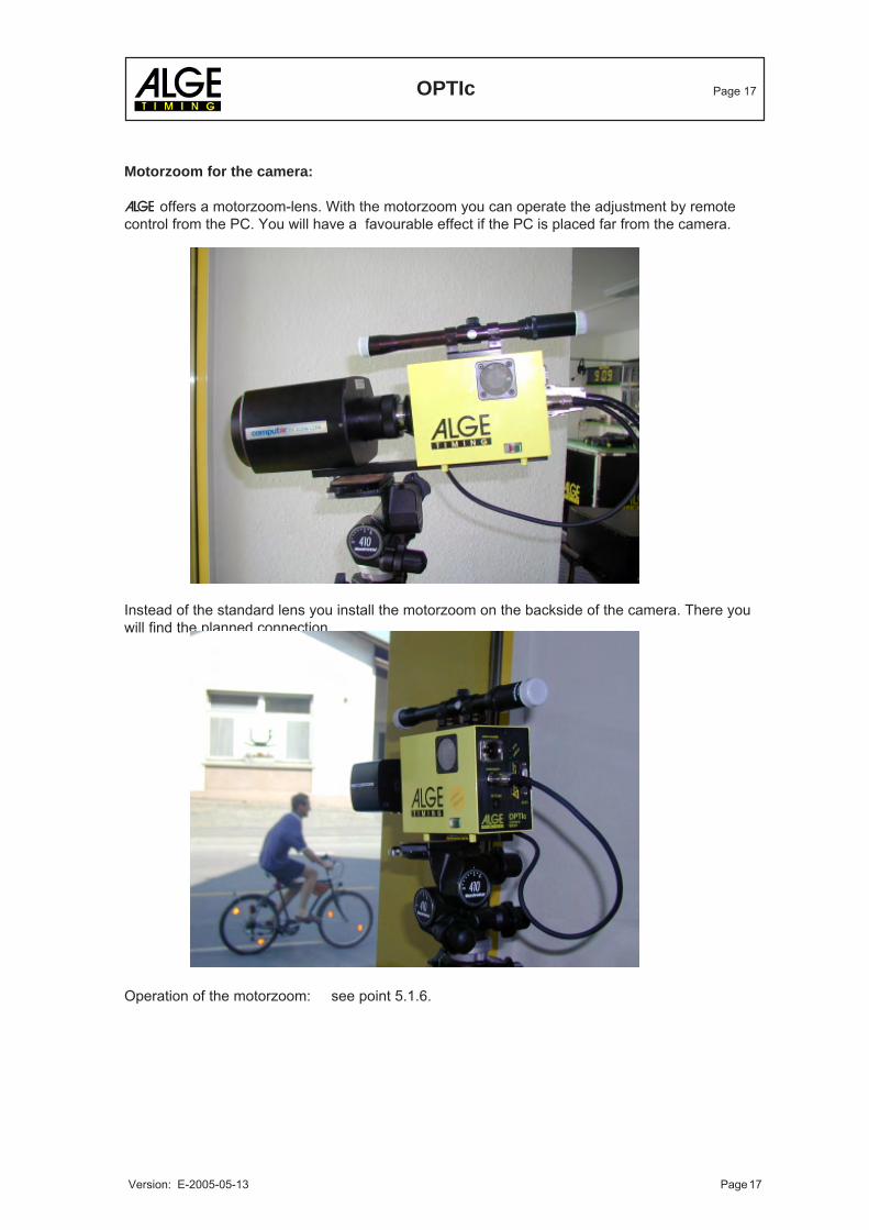
Motorzoom for the camera:
ALGE offers a motorzoom-lens. With the motorzoom you can operate the adjustment by remotecontrol from the PC. You will have a favourable effect if the PC is placed far from the camera.
Instead of the standard lens you install the motorzoom on the backside of the camera. There youwill find the planned connection.
Operation of the motorzoom: see point 5.1.6.
OPTIc Page 18
Version: E-2005-05-13 Page 18
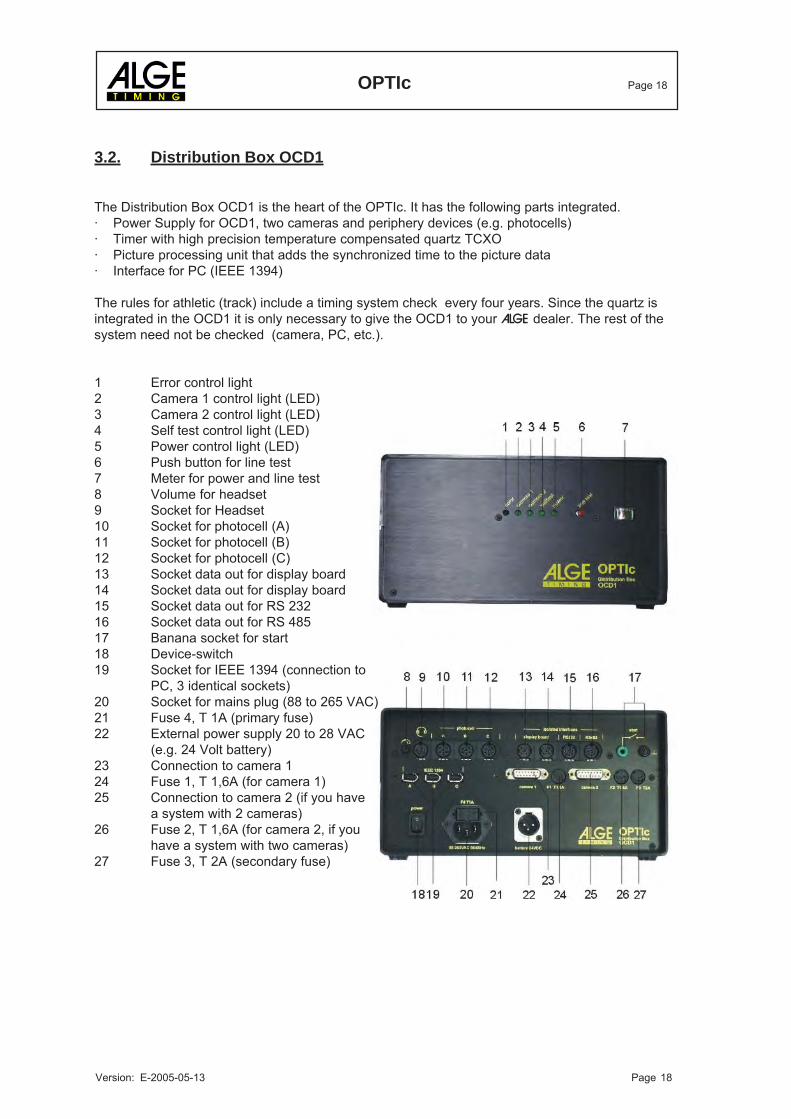
3.2. Distribution Box OCD1
The Distribution Box OCD1 is the heart of the OPTIc. It has the following parts integrated.· Power Supply for OCD1, two cameras and periphery devices (e.g. photocells)· Timer with high precision temperature compensated quartz TCXO· Picture processing unit that adds the synchronized time to the picture data· Interface for PC (IEEE 1394)
The rules for athletic (track) include a timing system check every four years. Since the quartz isintegrated in the OCD1 it is only necessary to give the OCD1 to your ALGE dealer. The rest of thesystem need not be checked (camera, PC, etc.).
1 Error control light2 Camera 1 control light (LED)3 Camera 2 control light (LED)4 Self test control light (LED)5 Power control light (LED)6 Push button for line test7 Meter for power and line test8 Volume for headset9 Socket for Headset10 Socket for photocell (A)11 Socket for photocell (B)12 Socket for photocell (C)13 Socket data out for display board14 Socket data out for display board15 Socket data out for RS 23216 Socket data out for RS 48517 Banana socket for start18 Device-switch19 Socket for IEEE 1394 (connection to
PC, 3 identical sockets)20 Socket for mains plug (88 to 265 VAC)21 Fuse 4, T 1A (primary fuse)22 External power supply 20 to 28 VAC
(e.g. 24 Volt battery)23 Connection to camera 124 Fuse 1, T 1,6A (for camera 1)25 Connection to camera 2 (if you have
a system with 2 cameras)26 Fuse 2, T 1,6A (for camera 2, if you
have a system with two cameras)27 Fuse 3, T 2A (secondary fuse)
OPTIc Page 19
Version: E-2005-05-13 Page 19
Finish Line
Track 1 Track 8
camera
2 Meter
Track 1 to 8 min. 5 m
min. 20 °
min. 5 mTrack 1 to 8
Objective angle
about 25° at 768 pixel
4. ADJUSTMENT OF THE LINE SCAN CAMERA OCC1
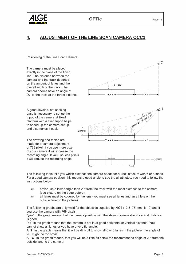
Positioning of the Line Scan Camera:
The camera must be placedexactly in the plane of the finishline. The distance between thecamera and the track dependson the amount of lanes and theoverall width of the track. Thecamera should have an angle of20o to the track at the farest distance.
A good, leveled, not shakingbase is necessary to set up thetripod of the camera. A fixedplatform with a fixed tripod helpsto speed up the camera set upand alsomakes it easier.
The drawing and tables aremade for a camera adjustmentof 768 pixel. If you use more pixelof your camera it will increase therecording angle. If you use less pixelsit will reduce the recording angle.
The following table tells you which distance the camera needs for a track stadium with 6 or 8 lanes.For a good camera position, this means a good angle to see the all athletes, you need to follow theinstructions below:
never use a lower angle than 20o from the track with the most distance to the camera(see picture on the page before).all lanes must be covered by the lens (you must see all lanes and an athlete on theoutside lane on the picture).
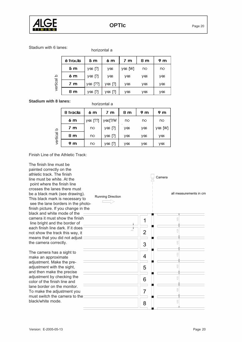
The following graphs are only valid for the objective supplied by ALGE (12,5 -75 mm, 1:1,2) and ifyou use the camera with 768 pixels.“yes” in the graph means that the camera position with the shown horizontal and vertical distanceis good.“no” in the graph means that the camera is not in at good horizontal or vertical distance. Youcannot show all lanes or you have a very flat angle.A “?” in the graph means that it will be difficult to show all 6 or 8 lanes in the picture (the angle of25o might be too small).A “W” in the graph means, that you will be a little bit below the recommended angle of 20o from theoutside lane to the camera.
OPTIc Page 20
Version: E-2005-05-13 Page 20
verti
cal b
verti
cal b
horizontal a
horizontal a
7
8
5
6
4
3
Running Direction
2
1
Camera
all measurements in cm
Stadium with 6 lanes:
Stadium with 8 lanes:
Finish Line of the Athletic Track:
The finish line must bepainted correctly on theathletic track. The finishline must be white. At the point where the finish linecrosses the lanes there mustbe a black mark (see drawing).This black mark is necessary to see the lane borders in the photo-finish picture. If you change in theblack and white mode of thecamera it must show the finish line bright and the border ofeach finish line dark. If it doesnot show the track this way, itmeans that you did not adjustthe camera correctly.
The camera has a sight tomake an approximateadjustment. Make the pre-adjustment with the sight,and then make the preciseadjustment by checking thecolor of the finish line andlane border on the monitor.To make the adjustment youmust switch the camera to theblack/white mode.
OPTIc Page 21
Version: E-2005-05-13 Page 21
Background
Lane 1
Lane 2
Lane 6
Lane 5
Lane 4
Lane 3
correct adjustmenta wrong adjustment
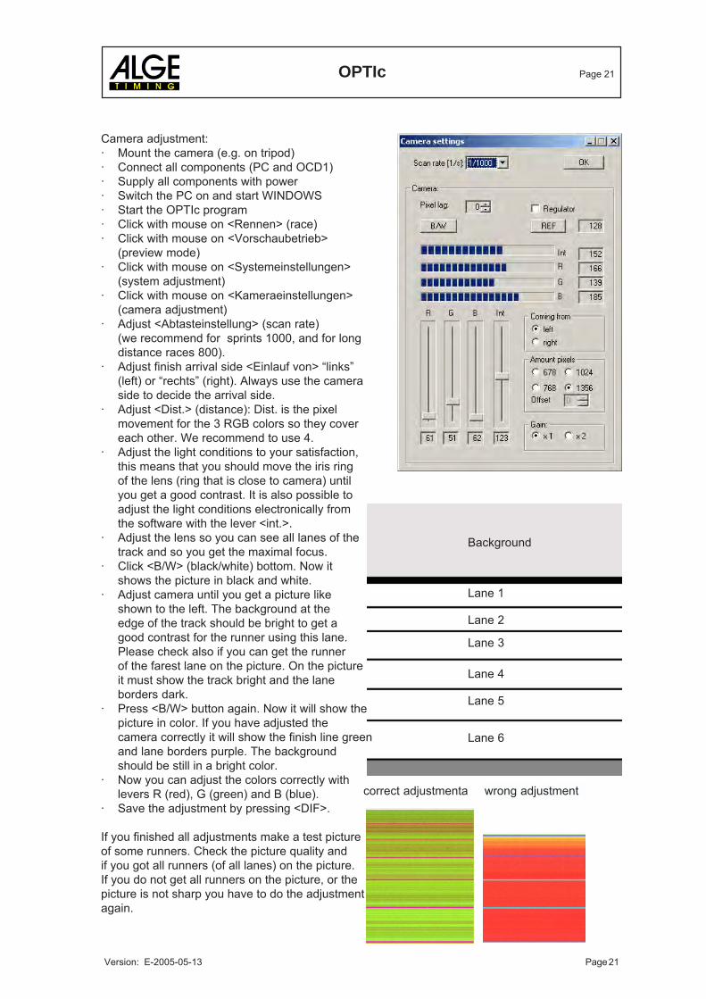
Camera adjustment:· Mount the camera (e.g. on tripod)· Connect all components (PC and OCD1)· Supply all components with power· Switch the PC on and start WINDOWS· Start the OPTIc program· Click with mouse on <Rennen> (race)· Click with mouse on <Vorschaubetrieb>
(preview mode)· Click with mouse on <Systemeinstellungen>
(system adjustment)· Click with mouse on <Kameraeinstellungen>
(camera adjustment)· Adjust <Abtasteinstellung> (scan rate)
(we recommend for sprints 1000, and for longdistance races 800).
· Adjust finish arrival side <Einlauf von> “links”(left) or “rechts” (right). Always use the cameraside to decide the arrival side.
· Adjust <Dist.> (distance): Dist. is the pixelmovement for the 3 RGB colors so they covereach other. We recommend to use 4.
· Adjust the light conditions to your satisfaction,this means that you should move the iris ringof the lens (ring that is close to camera) untilyou get a good contrast. It is also possible toadjust the light conditions electronically fromthe software with the lever <int.>.
· Adjust the lens so you can see all lanes of thetrack and so you get the maximal focus.
· Click <B/W> (black/white) bottom. Now itshows the picture in black and white.
· Adjust camera until you get a picture likeshown to the left. The background at theedge of the track should be bright to get agood contrast for the runner using this lane.Please check also if you can get the runnerof the farest lane on the picture. On the pictureit must show the track bright and the laneborders dark.
· Press <B/W> button again. Now it will show thepicture in color. If you have adjusted thecamera correctly it will show the finish line greenand lane borders purple. The backgroundshould be still in a bright color.
· Now you can adjust the colors correctly withlevers R (red), G (green) and B (blue).
· Save the adjustment by pressing <DIF>.
If you finished all adjustments make a test pictureof some runners. Check the picture quality andif you got all runners (of all lanes) on the picture.If you do not get all runners on the picture, or thepicture is not sharp you have to do the adjustmentagain.
OPTIc Page 22
Version: E-2005-05-13 Page 22
Background
Lane 1
Lane 2
Lane 6
Lane 5
Lane 4
Lane 3
Background
Lane 1
Lane 2
Lane 6
Lane 5
Lane 4
Lane 3
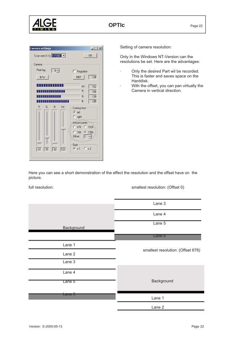
Setting of camera resolution:
Only in the Windows NT-Version can theresolutions be set. Here are the advantages:
· Only the desired Part wil be recorded.This is faster and saves space on theHarddisk.
· With the offset, you can pan virtually theCamera in vertical direction.
Here you can see a short demonstration of the effect the resolution and the offset have on thepicture.
full resolution: smallest resolution: (Offset 0)
smallest resolution: (Offset 678)
OPTIc Page 23
Version: E-2005-05-13 Page 23
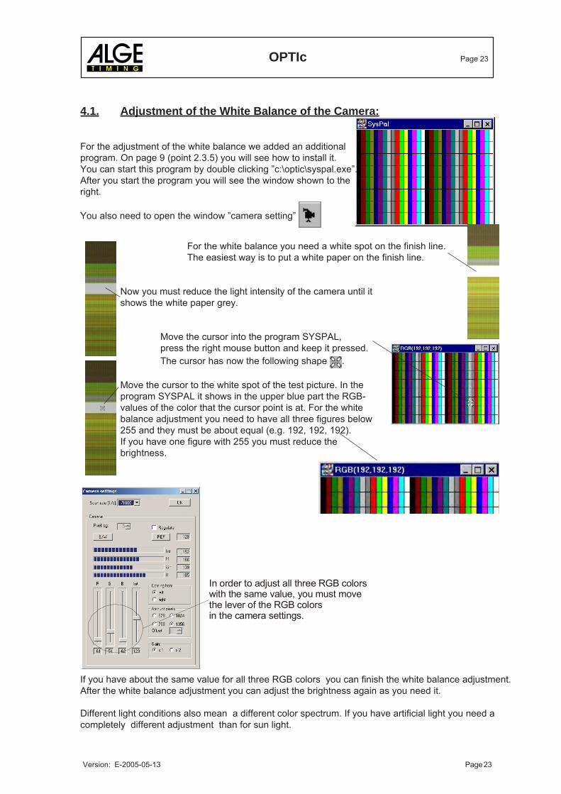
4.1. Adjustment of the White Balance of the Camera:
For the adjustment of the white balance we added an additionalprogram. On page 9 (point 2.3.5) you will see how to install it.You can start this program by double clicking ”c:\optic\syspal.exe”.After you start the program you will see the window shown to theright.
You also need to open the window ”camera setting”
For the white balance you need a white spot on the finish line.The easiest way is to put a white paper on the finish line.
Now you must reduce the light intensity of the camera until itshows the white paper grey.
Move the cursor into the program SYSPAL,press the right mouse button and keep it pressed.The cursor has now the following shape .
Move the cursor to the white spot of the test picture. In theprogram SYSPAL it shows in the upper blue part the RGB-values of the color that the cursor point is at. For the whitebalance adjustment you need to have all three figures below255 and they must be about equal (e.g. 192, 192, 192).If you have one figure with 255 you must reduce thebrightness.
If you have about the same value for all three RGB colors you can finish the white balance adjustment.After the white balance adjustment you can adjust the brightness again as you need it.
Different light conditions also mean a different color spectrum. If you have artificial light you need acompletely different adjustment than for sun light.
In order to adjust all three RGB colors with the same value, you must move the lever of the RGB colorsin the camera settings.
OPTIc Page 24
Version: E-2005-05-13 Page 24
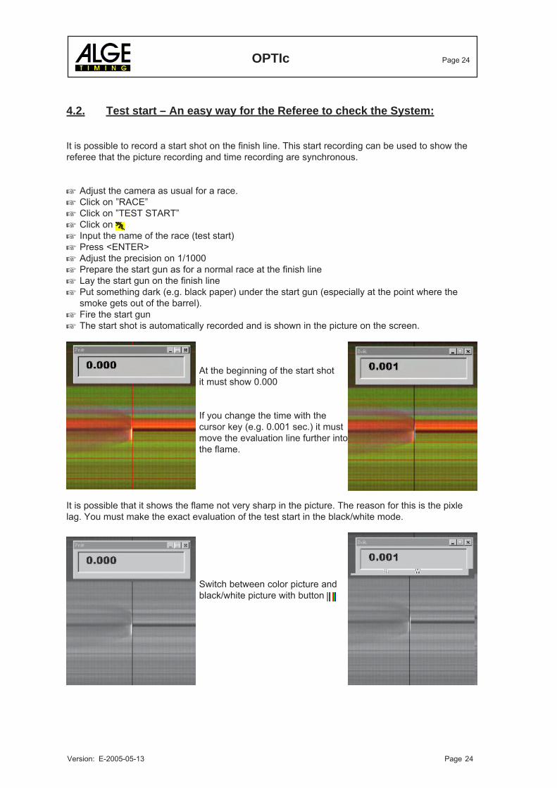
4.2. Test start – An easy way for the Referee to check the System:
It is possible to record a start shot on the finish line. This start recording can be used to show thereferee that the picture recording and time recording are synchronous.
Adjust the camera as usual for a race.Click on ”RACE”Click on ”TEST START”Click on Input the name of the race (test start)Press <ENTER>Adjust the precision on 1/1000Prepare the start gun as for a normal race at the finish lineLay the start gun on the finish linePut something dark (e.g. black paper) under the start gun (especially at the point where thesmoke gets out of the barrel).Fire the start gunThe start shot is automatically recorded and is shown in the picture on the screen.
At the beginning of the start shotit must show 0.000
If you change the time with thecursor key (e.g. 0.001 sec.) it mustmove the evaluation line further intothe flame.
It is possible that it shows the flame not very sharp in the picture. The reason for this is the pixlelag. You must make the exact evaluation of the test start in the black/white mode.
Switch between color picture andblack/white picture with button
OPTIc Page 25
Version: E-2005-05-13 Page 25
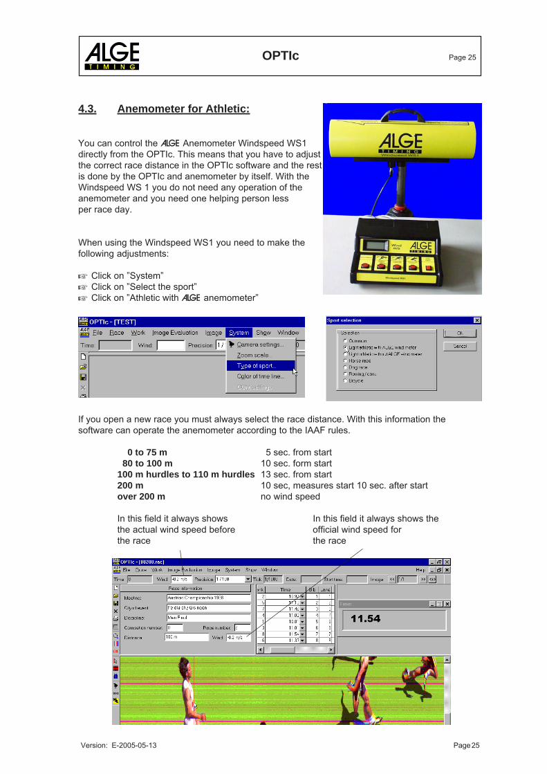
4.3. Anemometer for Athletic:
You can control the ALGE Anemometer Windspeed WS1directly from the OPTIc. This means that you have to adjustthe correct race distance in the OPTIc software and the restis done by the OPTIc and anemometer by itself. With theWindspeed WS 1 you do not need any operation of theanemometer and you need one helping person lessper race day.
When using the Windspeed WS1 you need to make thefollowing adjustments:
Click on ”System”Click on ”Select the sport”Click on ”Athletic with ALGE anemometer”
If you open a new race you must always select the race distance. With this information thesoftware can operate the anemometer according to the IAAF rules.
0 to 75 m 5 sec. from start 80 to 100 m 10 sec. form start100 m hurdles to 110 m hurdles 13 sec. from start200 m 10 sec, measures start 10 sec. after startover 200 m no wind speed
In this field it always shows In this field it always shows thethe actual wind speed before official wind speed forthe race the race
OPTIc Page 26
Version: E-2005-05-13 Page 26
5. SOFTWARE
The software of the OPTIc runs with Windows 95 (Version B or newer) and Windows NT (ServicePack 3 or higher). The IEEE 1394 driver does not support Windows 98.
If you do record with the OPTIc it is necessary to close all other programs. Other programs mightthe processor or hard disk, this means that the recording durance could be reduced.
The software meet the Windows standard. People using other Windows software will not have anyproblems with this program.
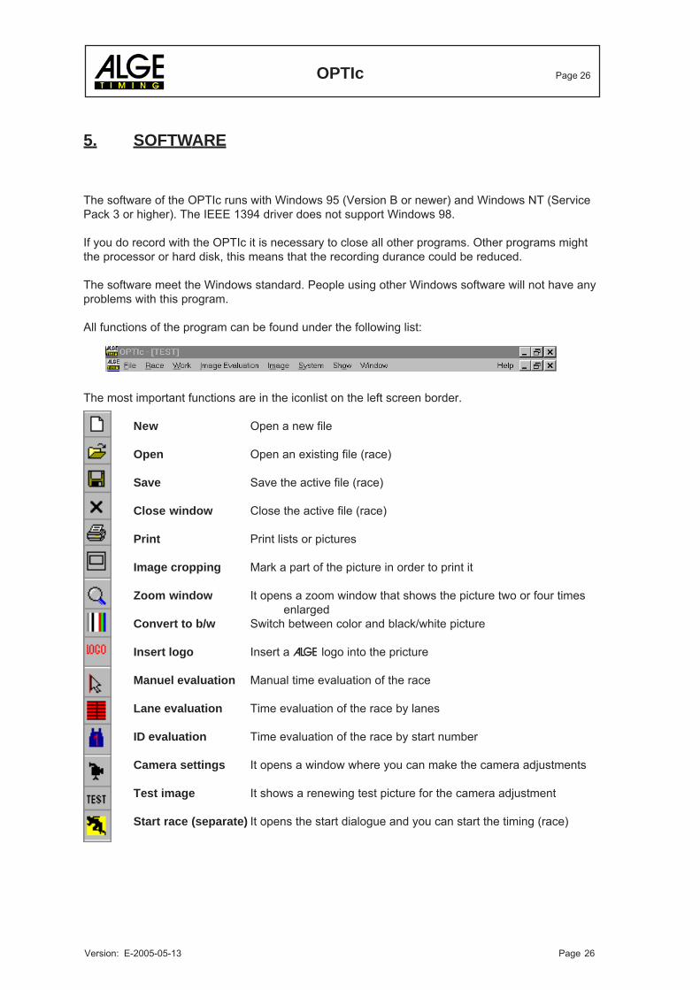
All functions of the program can be found under the following list:
The most important functions are in the iconlist on the left screen border.
New Open a new file
Open Open an existing file (race)
Save Save the active file (race)
Close window Close the active file (race)
Print Print lists or pictures
Image cropping Mark a part of the picture in order to print it
Zoom window It opens a zoom window that shows the picture two or four timesenlarged
Convert to b/w Switch between color and black/white picture
Insert logo Insert a ALGE logo into the pricture
Manuel evaluation Manual time evaluation of the race
Lane evaluation Time evaluation of the race by lanes
ID evaluation Time evaluation of the race by start number
Camera settings It opens a window where you can make the camera adjustments
Test image It shows a renewing test picture for the camera adjustment
Start race (separate) It opens the start dialogue and you can start the timing (race)
OPTIc Page 27
Version: E-2005-05-13 Page 27
5.1. Menus of the Software:
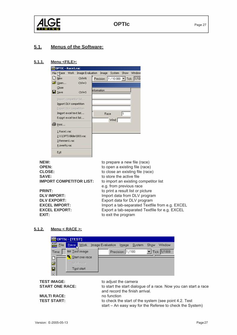
5.1.1. Menu <FILE>:
NEW: to prepare a new file (race)OPEN: to open a existing file (race)CLOSE: to close an existing file (race)SAVE: to store the active fileIMPORT COMPETITOR LIST: to import an existing competitor list
e.g. from previous racePRINT: to print a result list or pictureDLV IMPORT: Import data from DLV programDLV EXPORT: Export data for DLV programEXCEL IMPORT: Import a tab-separated Textfile from e.g. EXCELEXCEL EXPORT: Export a tab-separated Textfile for e.g. EXCELEXIT: to exit the program
5.1.2. Menu < RACE >:
TEST IMAGE: to adjust the cameraSTART ONE RACE: to start the start dialogue of a race. Now you can start a race
and record the finish arrival.MULTI RACE: no functionTEST START: to check the start of the system (see point 4.2. Test
start – An easy way for the Referee to check the System)
OPTIc Page 28
Version: E-2005-05-13 Page 28
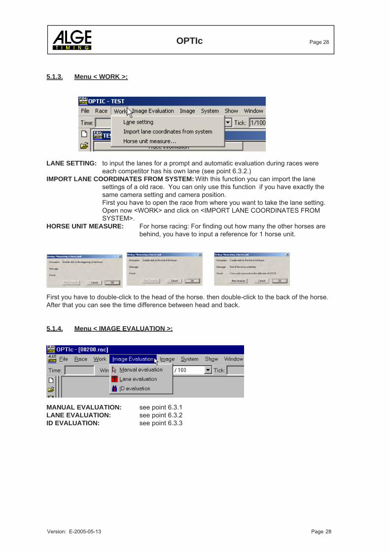
5.1.3. Menu < WORK >:
LANE SETTING: to input the lanes for a prompt and automatic evaluation during races wereeach competitor has his own lane (see point 6.3.2.)
IMPORT LANE COORDINATES FROM SYSTEM: With this function you can import the lanesettings of a old race. You can only use this function if you have exactly thesame camera setting and camera position.First you have to open the race from where you want to take the lane setting.Open now <WORK> and click on <IMPORT LANE COORDINATES FROMSYSTEM>.
HORSE UNIT MEASURE: For horse racing: For finding out how many the other horses arebehind, you have to input a reference for 1 horse unit.
First you have to double-click to the head of the horse. then double-click to the back of the horse.After that you can see the time difference between head and back.
5.1.4. Menu < IMAGE EVALUATION >:
MANUAL EVALUATION: see point 6.3.1LANE EVALUATION: see point 6.3.2ID EVALUATION: see point 6.3.3
OPTIc Page 29
Version: E-2005-05-13 Page 29
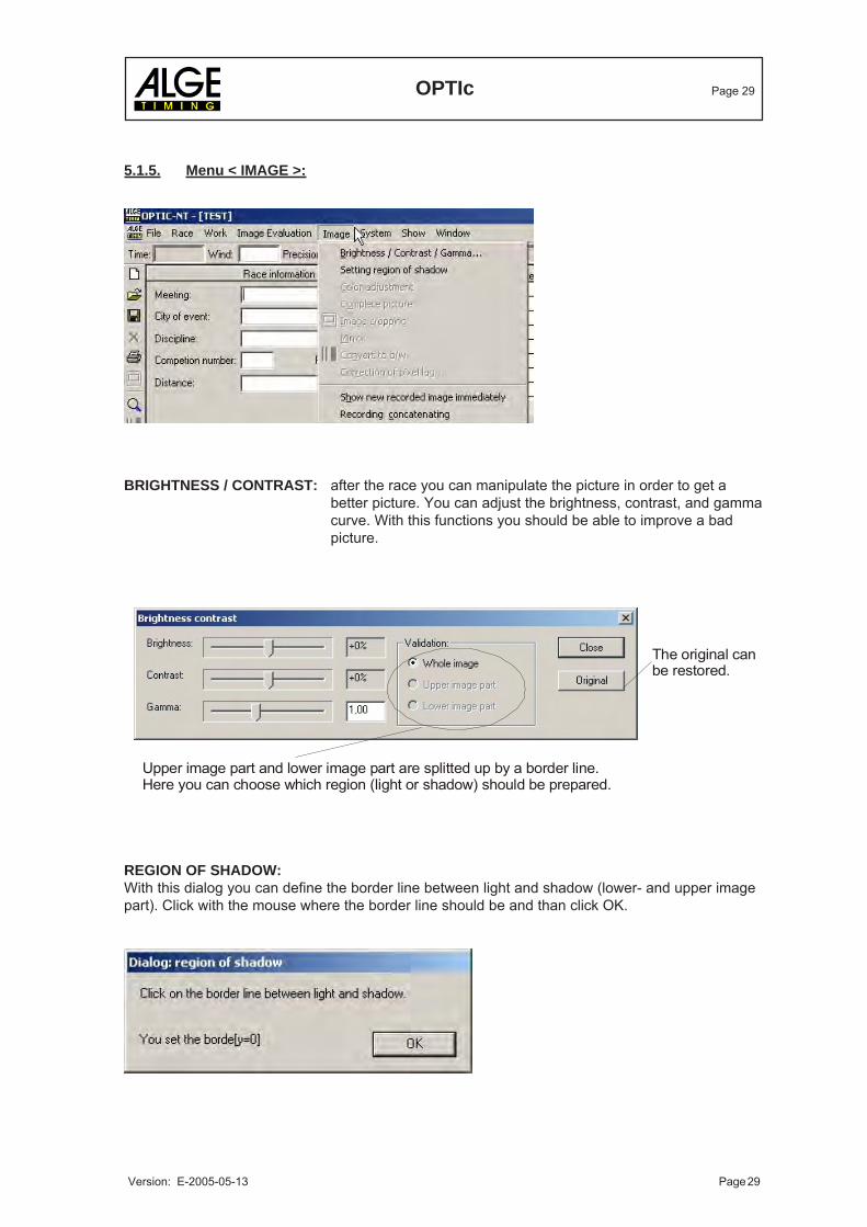
The original can be restored.
Upper image part and lower image part are splitted up by a border line.Here you can choose which region (light or shadow) should be prepared.
5.1.5. Menu < IMAGE >:
BRIGHTNESS / CONTRAST: after the race you can manipulate the picture in order to get abetter picture. You can adjust the brightness, contrast, and gammacurve. With this functions you should be able to improve a badpicture.
REGION OF SHADOW:With this dialog you can define the border line between light and shadow (lower- and upper imagepart). Click with the mouse where the border line should be and than click OK.
OPTIc Page 30
Version: E-2005-05-13 Page 30
IMAGE CROPPING: with this function you can mark a part of the picture, if you want to printpart of a picture. Click with the mouse into the picture and keep themouse pressed. Now move the mouse in the picture. You will see now arectangle that marks the part of the picture that you want to print.
MIRROR: no function yetCONVERT TO B/W: you can switch between color and black/white picture. Especially if you
need more sharpness in your picture you can switch on the b/w picture.This function is very handy if you have a wrong pixel lag adjusted. In theb/w picture it always takes the green (middle) sensor as reference.
CORRECTION OF PIXEL LAG: if the RGB colors does not cover each other (e.g. wrongspeed adjusted) you can correct it. As reference wealwaystake the green (middle) sensor.
SHOW NEW RECORDED IMAGE IMMEDIATELY: if you have this function activated (smallpick) it will always show you automatically the actual picture (last picturerecorded) on the monitor. Normally this function is only used for controlfunction.
RECORDING CONCATENATING: if you activate this function (small pick) it will not make aseparate picture for each trigger impulse, but make a bigger file. Use thisunction especially for competitions where you have lanes (e.g. athleticsprints). If you do not have the picture automatically after the race youmust finish it by pressing ”finish race”
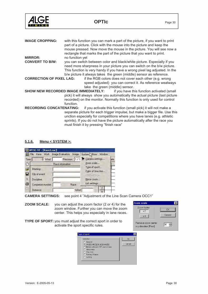
5.1.6. Menu < SYSTEM >:
CAMERA SETTINGS: see point 4 ”Adjustment of the Line Scan Camera OCC1”
ZOOM SCALE: you can adjust the zoom factor (2 or 4) for thezoom window. Further you can move the zoomcenter. This helps you especially in lane races.
TYPE OF SPORT: you must adjust the correct sport in order toactivate the sport specific rules.
OPTIc Page 31
Version: E-2005-05-13 Page 31
COLOR OF TIME LINE: you can select the color for the time line. Use always a color that has ahigh contrast with the background of the picture.
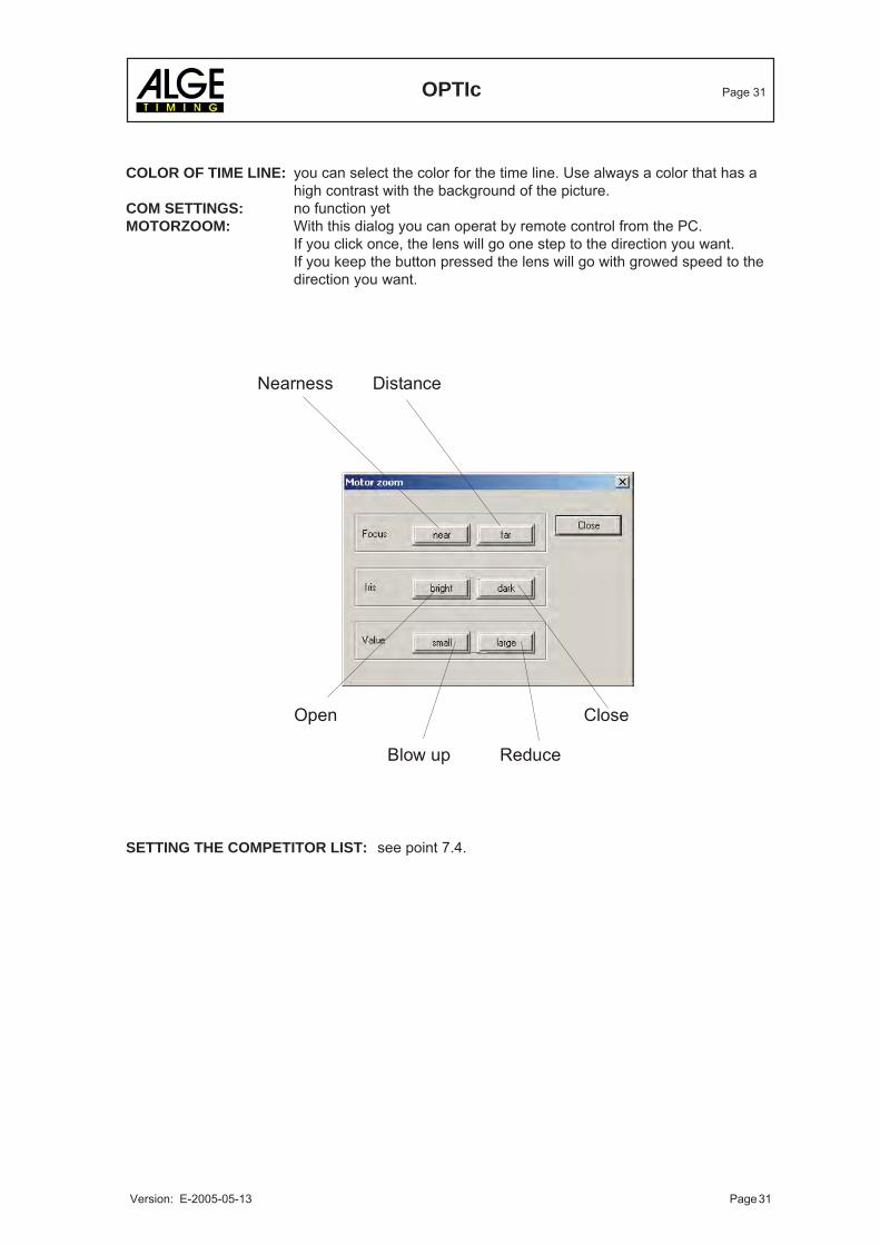
COM SETTINGS: no function yetMOTORZOOM: With this dialog you can operat by remote control from the PC.
If you click once, the lens will go one step to the direction you want.If you keep the button pressed the lens will go with growed speed to thedirection you want.
SETTING THE COMPETITOR LIST: see point 7.4.
Open Close Blow up Reduce
Nearness Distance
OPTIc Page 32
Version: E-2005-05-13 Page 32
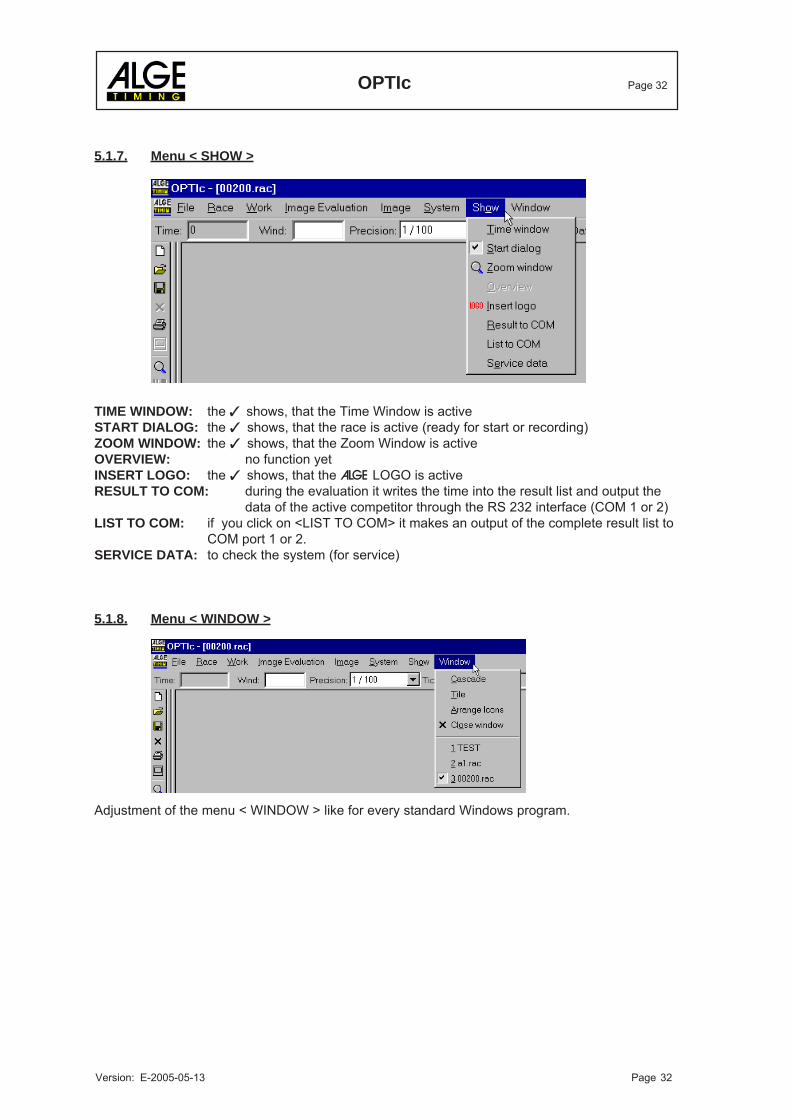
5.1.7. Menu < SHOW >
TIME WINDOW: the shows, that the Time Window is activeSTART DIALOG: the shows, that the race is active (ready for start or recording)ZOOM WINDOW: the shows, that the Zoom Window is activeOVERVIEW: no function yetINSERT LOGO: the shows, that the ALGE LOGO is activeRESULT TO COM: during the evaluation it writes the time into the result list and output the
data of the active competitor through the RS 232 interface (COM 1 or 2)LIST TO COM: if you click on <LIST TO COM> it makes an output of the complete result list to
COM port 1 or 2.SERVICE DATA: to check the system (for service)
5.1.8. Menu < WINDOW >
Adjustment of the menu < WINDOW > like for every standard Windows program.
OPTIc Page 33
Version: E-2005-05-13 Page 33
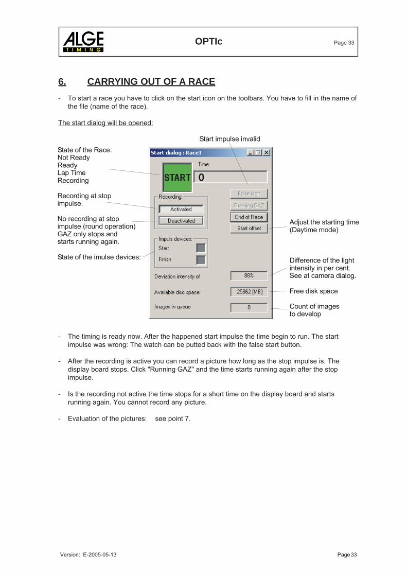
6. CARRYING OUT OF A RACE- To start a race you have to click on the start icon on the toolbars. You have to fill in the name of
the file (name of the race).
The start dialog will be opened:
- The timing is ready now. After the happened start impulse the time begin to run. The startimpulse was wrong: The watch can be putted back with the false start button.
- After the recording is active you can record a picture how long as the stop impulse is. Thedisplay board stops. Click "Running GAZ" and the time starts running again after the stopimpulse.
- Is the recording not active the time stops for a short time on the display board and startsrunning again. You cannot record any picture.
- Evaluation of the pictures: see point 7.
Start impulse invalid
Adjust the starting time(Daytime mode)
Difference of the lightintensity in per cent.See at camera dialog.
Free disk space
Count of images to develop
State of the Race:Not ReadyReadyLap TimeRecording
Recording at stopimpulse.
No recording at stopimpulse (round operation)GAZ only stops andstarts running again.
State of the imulse devices:
OPTIc Page 34
Version: E-2005-05-13 Page 34
7. EVALUATION
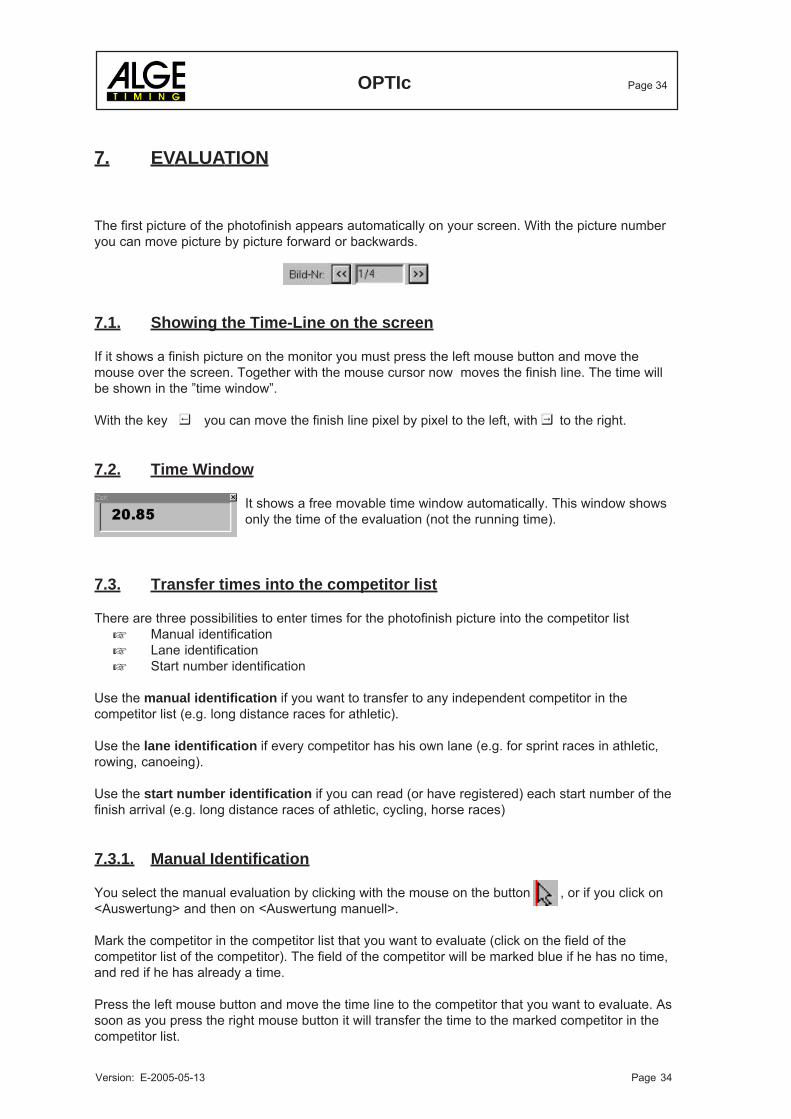
The first picture of the photofinish appears automatically on your screen. With the picture numberyou can move picture by picture forward or backwards.
7.1. Showing the Time-Line on the screen
If it shows a finish picture on the monitor you must press the left mouse button and move themouse over the screen. Together with the mouse cursor now moves the finish line. The time willbe shown in the ”time window”.
With the key you can move the finish line pixel by pixel to the left, with to the right.
7.2. Time Window
It shows a free movable time window automatically. This window showsonly the time of the evaluation (not the running time).
7.3. Transfer times into the competitor list
There are three possibilities to enter times for the photofinish picture into the competitor listManual identificationLane identificationStart number identification
Use the manual identification if you want to transfer to any independent competitor in thecompetitor list (e.g. long distance races for athletic).
Use the lane identification if every competitor has his own lane (e.g. for sprint races in athletic,rowing, canoeing).
Use the start number identification if you can read (or have registered) each start number of thefinish arrival (e.g. long distance races of athletic, cycling, horse races)
7.3.1. Manual Identification
You select the manual evaluation by clicking with the mouse on the button , or if you click on<Auswertung> and then on <Auswertung manuell>.
Mark the competitor in the competitor list that you want to evaluate (click on the field of thecompetitor list of the competitor). The field of the competitor will be marked blue if he has no time,and red if he has already a time.
Press the left mouse button and move the time line to the competitor that you want to evaluate. Assoon as you press the right mouse button it will transfer the time to the marked competitor in thecompetitor list.
OPTIc Page 35
Version: E-2005-05-13 Page 35
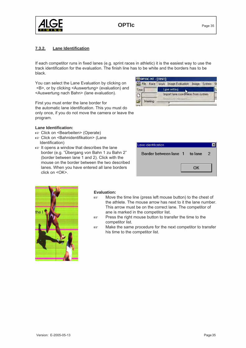
7.3.2. Lane Identification
If each competitor runs in fixed lanes (e.g. sprint races in athletic) it is the easiest way to use thetrack identification for the evaluation. The finish line has to be white and the borders has to beblack.
You can select the Lane Evaluation by clicking on <B>, or by clicking <Auswertung> (evaluation) and<Auswertung nach Bahn> (lane evaluation).
First you must enter the lane border forthe automatic lane identification. This you must doonly once, if you do not move the camera or leave theprogram.
Lane Identification:Click on <Bearbeiten> (Operate)Click on <Bahnidentifikation> (Lane
Identification)It opens a window that describes the laneborder (e.g. ”Übergang von Bahn 1 zu Bahn 2”(border between lane 1 and 2). Click with themouse on the border between the two describedlanes. When you have entered all lane bordersclick on <OK>.
Evaluation:Move the time line (press left mouse button) to the chest ofthe athlete. The mouse arrow has next to it the lane number.This arrow must be on the correct lane. The competitor of
the l ane is marked in the competitor list.Press the right mouse button to transfer the time to thecompetitor list.Make the same procedure for the next competitor to transferhis time to the competitor list.
OPTIc Page 36
Version: E-2005-05-13 Page 36
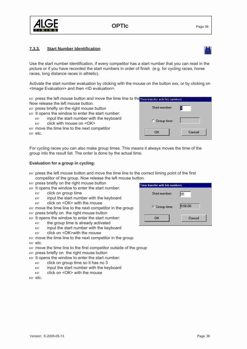
7.3.3. Start Number Identification
Use the start number identification, if every competitor has a start number that you can read in thepicture or if you have recorded the start numbers in order of finish (e.g. for cycling races, horseraces, long distance races in athletic).
Activate the start number evaluation by clicking with the mouse on the button xxx, or by clicking on<Image Evaluation> and then <ID evaluation>.
press the left mouse button and move the time line to the correct timing point of the competitor.Now release the left mouse button.
press briefly on the right mouse buttonIt opens the window to enter the start number:
input the start number with the keyboardclick with mouse on <OK>
move the time line to the next competitoretc.
For cycling races you can also make group times. This means it always moves the time of thegroup into the result list. The order is done by the actual time.
Evaluation for a group in cycling:
press the left mouse button and move the time line to the correct timing point of the firstcompetitor of the group. Now release the left mouse button.press briefly on the right mouse buttonIt opens the window to enter the start number:
click on group timeinput the start number with the keyboardclick on <OK> with the mouse
move the time line to the next competitor in the grouppress briefly on the right mouse buttonIt opens the window to enter the start number:
the group time is already activatedinput the start number with the keyboardclick on <OK>with the mouse
move the time line to the next competitor in the groupetc.move the time line to the first competitor outside of the grouppress briefly on the right mouse buttonIt opens the window to enter the start number:
click on group time so it has no 3input the start number with the keyboardclick on <OK> with the mouse
etc.
OPTIc Page 37
Version: E-2005-05-13 Page 37
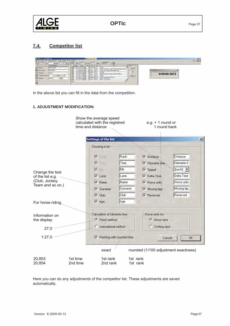
7.4. Competitor list
In the above list you can fill in the data from the competition.
1. ADJUSTMENT MODIFICATION:
Here you can do any adjustments of the competitor list. These adjustments are savedautomatically.
Show the average speedcalculated with the registred e.g. + 1 round ortime and distance 1 round back
Change the textof the list e.g. (Club, Jockey,Team and so on.)
For horse riding
Information onthe display
27,0
1:27,0
exact rounded (1/100 adjustment exactness)
20,853 1st time 1st rank 1st rank20,854 2nd time 2nd rank 1st rank

OPTIc Page 38
Version: E-2005-05-13 Page 38
2. DESCRIPTION OF THE SPLIT:
Distance: Here you can fill in the distance of the race which you will need for yourcalculation.
Time of kilometre: Special calculation for the horse riding.
Speed: You can calculate the average speed with the registered time and distance.
Delta time: Distance between the first and the the other competitors.
Horse units: E.g. half a horse length. With the registered time it will be calculatedautomatically.
Missing laps: Special for motorsport.
Reserved: Reserved for further applications.
3. SPECIAL FUNCTIONS:
a) Sort: You can sort the list after each split e.g. click split "rank" to sort after rank.
b) Distance: Is there no distance in the list, the distance from the competition will befilled in automatically.
OPTIc Page 39
Version: E-2005-05-13 Page 39
Box OCD1Distribution
Speech Amplifier
SV4/SM
Headset Q34
SM
8
Startgun
8. OPTIc OPTIONS
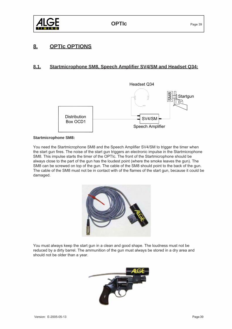
8.1. Startmicrophone SM8, Speech Amplifier SV4/SM and Headset Q34:
Startmicrophone SM8:
You need the Startmicrophone SM8 and the Speech Amplifier SV4/SM to trigger the timer whenthe start gun fires. The noise of the start gun triggers an electronic impulse in the StartmicrophoneSM8. This impulse starts the timer of the OPTIc. The front of the Startmicrophone should bealways close to the part of the gun has the loudest point (where the smoke leaves the gun). TheSM8 can be screwed on top of the gun. The cable of the SM8 should point to the back of the gun.The cable of the SM8 must not be in contact with of the flames of the start gun, because it could bedamaged.
You must always keep the start gun in a clean and good shape. The loudness must not bereduced by a dirty barrel. The ammunition of the gun must always be stored in a dry area andshould not be older than a year.
OPTIc Page 40
Version: E-2005-05-13 Page 40
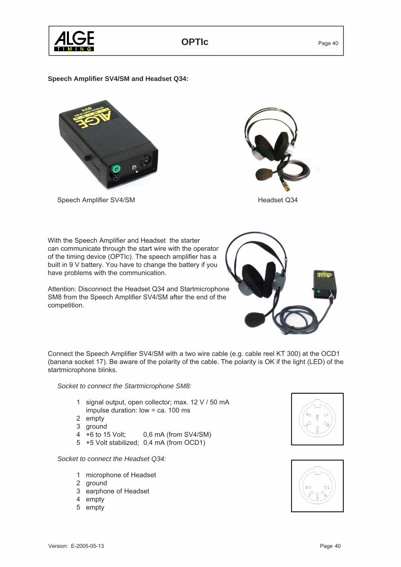
Speech Amplifier SV4/SM and Headset Q34:
Speech Amplifier SV4/SM Headset Q34
With the Speech Amplifier and Headset the startercan communicate through the start wire with the operatorof the timing device (OPTIc). The speech amplifier has abuilt in 9 V battery. You have to change the battery if youhave problems with the communication.
Attention: Disconnect the Headset Q34 and StartmicrophoneSM8 from the Speech Amplifier SV4/SM after the end of thecompetition.
Connect the Speech Amplifier SV4/SM with a two wire cable (e.g. cable reel KT 300) at the OCD1(banana socket 17). Be aware of the polarity of the cable. The polarity is OK if the light (LED) of thestartmicrophone blinks.
Socket to connect the Startmicrophone SM8:
1 signal output, open collector; max. 12 V / 50 mAimpulse duration: low = ca. 100 ms
2 empty3 ground4 +6 to 15 Volt; 0,6 mA (from SV4/SM)5 +5 Volt stabilized; 0,4 mA (from OCD1)
Socket to connect the Headset Q34:
1 microphone of Headset2 ground3 earphone of Headset4 empty5 empty
OPTIc Page 41
Version: E-2005-05-13 Page 41
Alkaline b aby battery, 1,5 Vor NiCd rechargeable babybattery 1,2 Volt
8.2. Photocell:
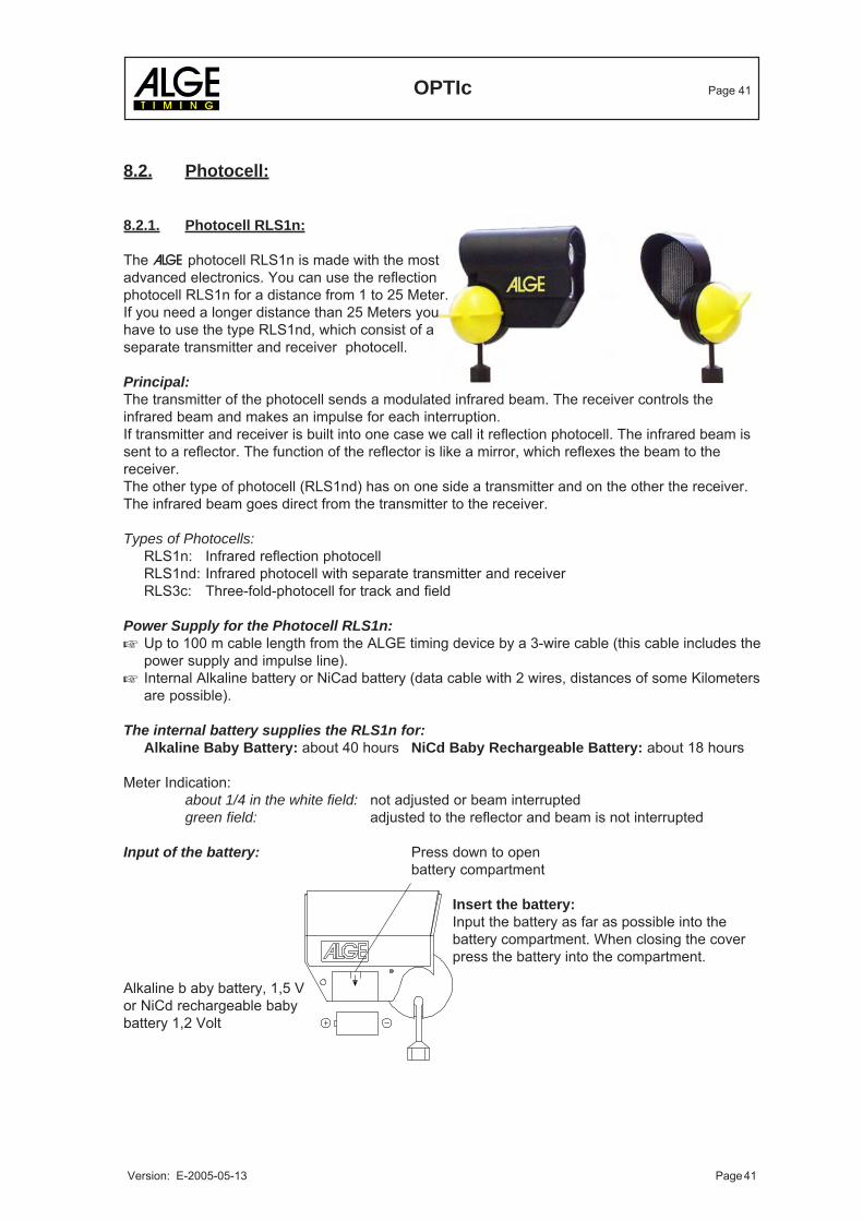
8.2.1. Photocell RLS1n:
The ALGE photocell RLS1n is made with the mostadvanced electronics. You can use the reflectionphotocell RLS1n for a distance from 1 to 25 Meter.If you need a longer distance than 25 Meters youhave to use the type RLS1nd, which consist of aseparate transmitter and receiver photocell.
Principal:The transmitter of the photocell sends a modulated infrared beam. The receiver controls theinfrared beam and makes an impulse for each interruption.If transmitter and receiver is built into one case we call it reflection photocell. The infrared beam issent to a reflector. The function of the reflector is like a mirror, which reflexes the beam to thereceiver.The other type of photocell (RLS1nd) has on one side a transmitter and on the other the receiver.The infrared beam goes direct from the transmitter to the receiver.
Types of Photocells:RLS1n: Infrared reflection photocellRLS1nd: Infrared photocell with separate transmitter and receiverRLS3c: Three-fold-photocell for track and field
Power Supply for the Photocell RLS1n:Up to 100 m cable length from the ALGE timing device by a 3-wire cable (this cable includes thepower supply and impulse line).Internal Alkaline battery or NiCad battery (data cable with 2 wires, distances of some Kilometersare possible).
The internal battery supplies the RLS1n for:Alkaline Baby Battery: about 40 hours NiCd Baby Rechargeable Battery: about 18 hours
Meter Indication:about 1/4 in the white field: not adjusted or beam interruptedgreen field: adjusted to the reflector and beam is not interrupted
Input of the battery: Press down to openbattery compartment
Insert the battery:Input the battery as far as possible into thebattery compartment. When closing the coverpress the battery into the compartment.

OPTIc Page 42
Version: E-2005-05-13 Page 42
Impulse length of 20 to 1400 ms adjustable(adjust with small screw driver)
Switch on of internal Battery:The internal battery of the photocell RLS1n can be switched on with switch (1).
upper position = battery on lower position = battery offAttention: If you use a battery be carefull that the battery is switched off when you do not use thephotocell. Otherwise the battery will be drained if you need the photocell the next time.If you use no battery the switch position does not matter.
Adjustment of the Photocell RLS1n:Fasten the fastening-bracket for the photocell and reflector at a poleScrew the photocell and reflector on the fastening-bracketTwist the reflector toward the photocellConnect the cable (e.g. 001-10) at the photocell and timing deviceTurn the timing device (and photocell if internal battery) onOpen the socket joint of the photocell (turn the yellow knob counter-clockwise)Aim at the reflector by using the sight on top of the photocellThe needle of the level meter has to move as far as possible into the green fieldClose the socket joint of the photocell (turn the yellow knob clockwise)If you interrupt the infrared beam of the photocell you hear a beep of the timing device. Theneedle of the lever moves into the white area.
Weather Cover:You can free out the weather cover in order to protect the lens fromsnow and rain.When using the RLS1n on a glacier please always use the weathercover.Please notice that the sun is not allowed to shine directly into thelense of the photocell. This could destroy the photocell.
Technical Data of the Photocell RLS1n:Max. Distance: 0,5 to 25 MeterOutput: NPN transistor, open collector, active lowReaction Time: 300 µs, 2 ms fix adjustedImpulse length: 20 to 1400 ms adjustableMeasurements: 160 x 135 x 58 mmWeight: 0,6 kgSwitch: on/off-switch for internal battery
DIN-Socket Pin Connection:1 Signal output2 Signal output3 0 Volt4 empty5 +5V stabilizedBanana Socket:red signal outputblack 0 Volt
Power Supply: external 5 VDC stabilizedinternal battery: BabyPower consumption: when giving an impulse max. 30mA
without impulse max. 15 mAWorking Time of Photocell RLS1n with Internal Battery:
about 40 hours with alkaline batteryabout 18 hours with rechargeable battery
OPTIc Page 43
Version: E-2005-05-13 Page 43
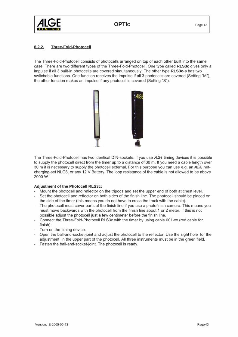
8.2.2. Three-Fold-Photocell
The Three-Fold-Photocell consists of photocells arranged on top of each other built into the samecase. There are two different types of the Three-Fold-Photocell. One type called RLS3c gives only aimpulse if all 3 built-in photocells are covered simultaneously. The other type RLS3c-s has twoswitchable functions. One function receives the impulse if all 3 photocells are covered (Setting "M"),the other function makes an impulse if any photocell is covered (Setting "S").
The Three-Fold-Photocell has two identical DIN-sockets. If you use ALGE timing devices it is possibleto supply the photocell direct from the timer up to a distance of 30 m. If you need a cable length over30 m it is necessary to supply the photocell external. For this purpose you can use e.g. an ALGE net-charging-set NLG8, or any 12 V Battery. The loop resistance of the cable is not allowed to be above2000 W.
Adjustment of the Photocell RLS3c:- Mount the photocell and reflector on the tripods and set the upper end of both at chest level.- Set the photocell and reflector on both sides of the finish line. The photocell should be placed on
the side of the timer (this means you do not have to cross the track with the cable).- The photocell must cover parts of the finish line if you use a photofinish camera. This means you
must move backwards with the photocell from the finish line about 1 or 2 meter. If this is notpossible adjust the photocell just a few centimeter before the finish line.
- Connect the Three-Fold-Photocell RLS3c with the timer by using cable 001-xx (red cable forfinish).
- Turn on the timing device.- Open the ball-and-socket-joint and adjust the photocell to the reflector. Use the sight hole for the
adjustment in the upper part of the photocell. All three instruments must be in the green field.- Fasten the ball-and-socket-joint. The photocell is ready.
OPTIc Page 44
Version: E-2005-05-13 Page 44
Attention:If the photocell is out of focus (or covered) the meter of the timing device starts to swing.The photocell and the reflector should be blocked off, so that no one can knock it during the race.
Used for: Athletic
Technical Data of the Three-Fold-Photocell RLS3c:Power Supply: 7 to 15 VDC (Pin 4)
or 5 VDC / 25 mA max. (Pin 5)Power Consumption: with 5 V supply form Timer S4:
not triggered: < 35 mAall 3 triggered: <50 mAwith 12 V supply (external):not triggered: < 40 mAall 3 triggered: <55 mA
Operating Distance: 2 to 15 MeterOutput: NPN transistor, Open Collector, activ lowReaction Time: 300 µs, 2 ms adjustedImpulse Length: 20 to 1400 ms, adjustableMeasurements: 200 x 370 x 120 mmWeicht: 2 kg (RLS3c with Reflector)Socket Pin Arrangement:
1 Signal output (start)2 Signal output (finish)3 0 Volt4 Power supply 7 to 15 VDC5 +5V stabilized
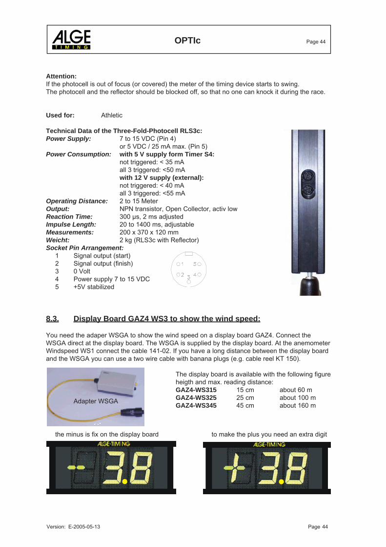
8.3. Display Board GAZ4 WS3 to show the wind speed:
You need the adaper WSGA to show the wind speed on a display board GAZ4. Connect theWSGA direct at the display board. The WSGA is supplied by the display board. At the anemometerWindspeed WS1 connect the cable 141-02. If you have a long distance between the display boardand the WSGA you can use a two wire cable with banana plugs (e.g. cable reel KT 150).
The display board is available with the following figureheigth and max. reading distance:GAZ4-WS315 15 cm about 60 mGAZ4-WS325 25 cm about 100 mGAZ4-WS345 45 cm about 160 mAdapter WSGA
the minus is fix on the display board to make the plus you need an extra digit
OPTIc Page 45
Version: E-2005-05-13 Page 45
9. TECHNICAL DATA
Measuring range: 23 hours, 59 minutes, 59,9999 seconds
Crystal frequency: TCXO 10,000 MHz (Temperature Compensated Crystal Oscillator)
Accuracy:at changeable temperature range from: -25 to +50oC: +/- 2,5 ppm at (+/- 0,009 s/h.)Aging: +/- 1 ppm per yearFrequency adjustment: +/- 0,1 ppm at 25oC
Temperature Operative Timing Range:: 0 to 50oC (xxxF to 122F)
Power Supply: 88 to 265 VAC (Distribution Box OCD1)
Memory: min. 64 MB RAM for the PCmin. 2 GB hard disk for the PC
Recording of Pictures: on the hard disk of PC
Storing the Races: - floppy disk- changeable hard disk- streamer- CD-R- CD-WR
Inpulse Input: input resistance 10 kW against +5Vresolution with <1 Volt (falling flank)hysterese ca. 2 Volt
Output 5V DC stabilized: total max. 120 mA
Speech Amplifier: communication through start cable
Operation keys: PC-keyboardmouse
External upply OCC1: 20-28V DCPinassignment: 1... 20-28V DC
2... GND3... free
OPTIc Page 46
Version: E-2005-05-13 Page 46
12 3
5 4
Display Board Interface "display board":
Transfer Format: 1 start bit, 8 data bit, no parity bit, 1 stop bitTransfer Speed: 2.400 BaudTransfer Protocol: ASCII
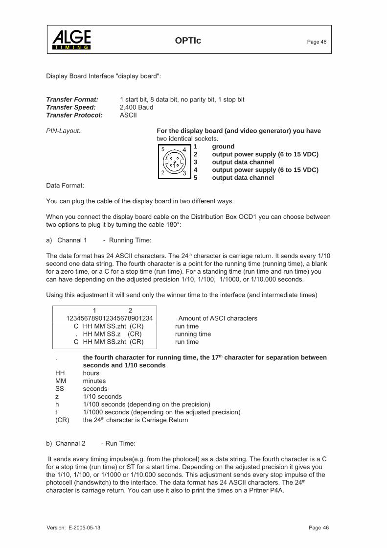
PIN-Layout: For the display board (and video generator) you havetwo identical sockets.
1 ground2 output power supply (6 to 15 VDC)3 output data channel4 output power supply (6 to 15 VDC)5 output data channel
Data Format:
You can plug the cable of the display board in two different ways.
When you connect the display board cable on the Distribution Box OCD1 you can choose betweentwo options to plug it by turning the cable 180°:
a) Channal 1 - Running Time:
The data format has 24 ASCII characters. The 24th character is carriage return. It sends every 1/10second one data string. The fourth character is a point for the running time (running time), a blankfor a zero time, or a C for a stop time (run time). For a standing time (run time and run time) youcan have depending on the adjusted precision 1/10, 1/100, 1/1000, or 1/10.000 seconds.
Using this adjustment it will send only the winner time to the interface (and intermediate times)
1 2 123456789012345678901234 Amount of ASCI characters
C HH MM SS.zht (CR) run time . HH MM SS.z (CR) running timeC HH MM SS.zht (CR) run time
. the fourth character for running time, the 17th character for separation betweenseconds and 1/10 seconds
HH hoursMM minutesSS secondsz 1/10 secondsh 1/100 seconds (depending on the precision)t 1/1000 seconds (depending on the adjusted precision)(CR) the 24th character is Carriage Return
b) Channal 2 - Run Time:
It sends every timing impulse(e.g. from the photocel) as a data string. The fourth character is a Cfor a stop time (run time) or ST for a start time. Depending on the adjusted precision it gives youthe 1/10, 1/100, or 1/1000 or 1/10.000 seconds. This adjustment sends every stop impulse of thephotocell (handswitch) to the interface. The data format has 24 ASCII characters. The 24th
character is carriage return. You can use it also to print the times on a Pritner P4A.
OPTIc Page 47
Version: E-2005-05-13 Page 47
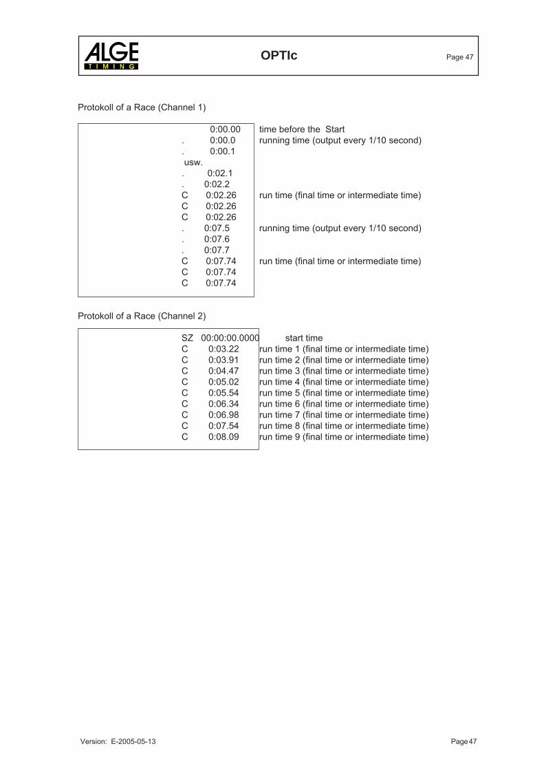
Protokoll of a Race (Channel 1)
0:00.00 time before the Start. 0:00.0 running time (output every 1/10 second). 0:00.1 usw.. 0:02.1. 0:02.2C 0:02.26 run time (final time or intermediate time)C 0:02.26C 0:02.26. 0:07.5 running time (output every 1/10 second). 0:07.6. 0:07.7C 0:07.74 run time (final time or intermediate time)C 0:07.74C 0:07.74
Protokoll of a Race (Channel 2)
SZ 00:00:00.0000 start timeC 0:03.22 run time 1 (final time or intermediate time)C 0:03.91 run time 2 (final time or intermediate time)C 0:04.47 run time 3 (final time or intermediate time)C 0:05.02 run time 4 (final time or intermediate time)C 0:05.54 run time 5 (final time or intermediate time)C 0:06.34 run time 6 (final time or intermediate time)C 0:06.98 run time 7 (final time or intermediate time)C 0:07.54 run time 8 (final time or intermediate time)C 0:08.09 run time 9 (final time or intermediate time)
OPTIc Page 48
Version: E-2005-05-13 Page 48
RS 232 Interface for Start List and Ranking List:
In order to send the start list and ranking list from the OPTIc e.g. to a Alphanumeric Display Boardwe use the RS 232 interface of the OPTIc-PC. You can adjust in the sinterface data for the OPTIcPC. The factory adjustment is the following:
COM-Port: COM 2Transfer Format: 1 start bit, 8 data bit, no parity bit, 1 stop bitTransfer Speed: 9.600 BaudTransfer Protocol: ASCII
This interface does output the complete data through of the result list through the COM port. Theoutput may be different, depending on the adjustments of the ranking list in the OPTIc.
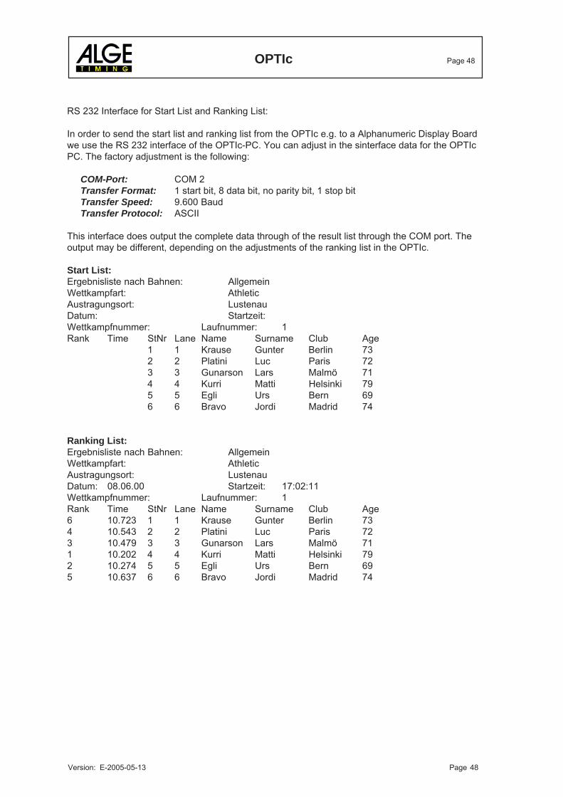
Start List:Ergebnisliste nach Bahnen: AllgemeinWettkampfart: AthleticAustragungsort: LustenauDatum: Startzeit:Wettkampfnummer: Laufnummer: 1Rank Time StNr Lane Name Surname Club Age
1 1 Krause Gunter Berlin 732 2 Platini Luc Paris 723 3 Gunarson Lars Malmö 714 4 Kurri Matti Helsinki 795 5 Egli Urs Bern 696 6 Bravo Jordi Madrid 74
Ranking List:Ergebnisliste nach Bahnen: AllgemeinWettkampfart: AthleticAustragungsort: LustenauDatum: 08.06.00 Startzeit: 17:02:11Wettkampfnummer: Laufnummer: 1Rank Time StNr Lane Name Surname Club Age6 10.723 1 1 Krause Gunter Berlin 734 10.543 2 2 Platini Luc Paris 723 10.479 3 3 Gunarson Lars Malmö 711 10.202 4 4 Kurri Matti Helsinki 792 10.274 5 5 Egli Urs Bern 695 10.637 6 6 Bravo Jordi Madrid 74
OPTIc Page 49
Version: E-2005-05-13 Page 49
10. ADDITION
10.1. Working with the registry:
Start and use of the record editor for further adjustment.You will not need in the normal usage and you should not change these adjustments.
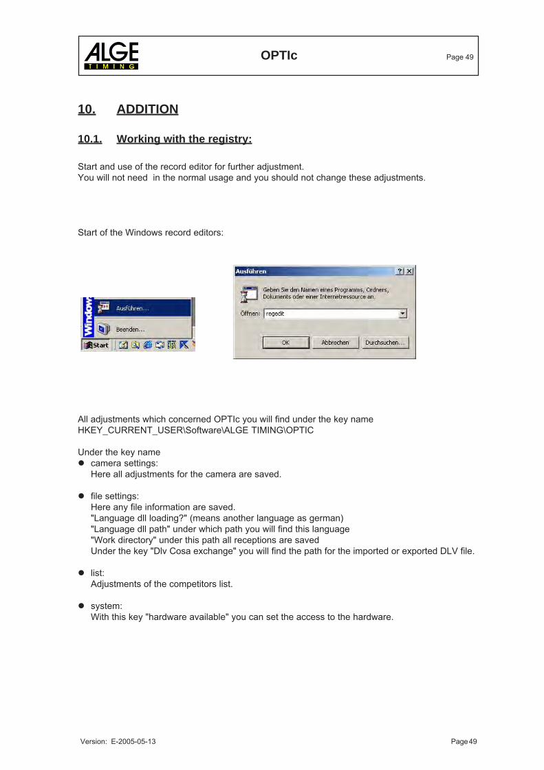
Start of the Windows record editors:
All adjustments which concerned OPTIc you will find under the key nameHKEY_CURRENT_USER\Software\ALGE TIMING\OPTIC
Under the key namecamera settings:Here all adjustments for the camera are saved.
file settings:Here any file information are saved."Language dll loading?" (means another language as german)"Language dll path" under which path you will find this language"Work directory" under this path all receptions are savedUnder the key "Dlv Cosa exchange" you will find the path for the imported or exported DLV file.
list:Adjustments of the competitors list.
system:With this key "hardware available" you can set the access to the hardware.
OPTIc Page 50
Version: E-2005-05-13 Page 50
10.2. Excel Import and Export functions from OPTIc Version 3.5:
This Function should be a little help for managing the result list of OPTIc. OPTIc does not produceresp. cannot read really EXCEL-Files. But Textfiles which are exported form EXCEL.To use this feature you have to pay attention for a view things:
The textfile has to look in this way:
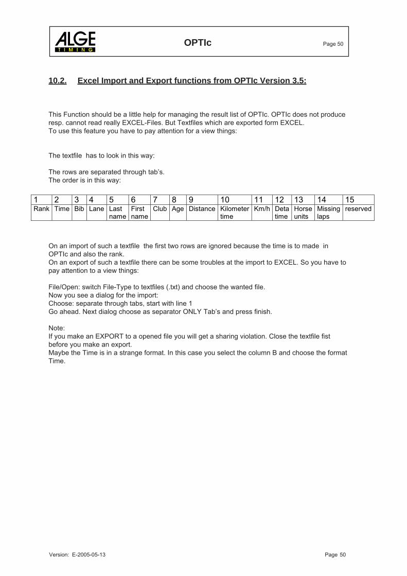
The rows are separated through tab’s.The order is in this way:
On an import of such a textfile the first two rows are ignored because the time is to made inOPTIc and also the rank.On an export of such a textfile there can be some troubles at the import to EXCEL. So you have topay attention to a view things:
File/Open: switch File-Type to textfiles (.txt) and choose the wanted file.Now you see a dialog for the import:Choose: separate through tabs, start with line 1Go ahead. Next dialog choose as separator ONLY Tab’s and press finish.
Note:If you make an EXPORT to a opened file you will get a sharing violation. Close the textfile fistbefore you make an export.Maybe the Time is in a strange format. In this case you select the column B and choose the formatTime.
1 2 3 4 5 6 7 8 9 10 11 12 13 14 15 Rank Time Bib Lane Last
name First name
Club Age Distance Kilometer time
Km/h Deta time
Horse units
Missing laps
reserved


![Fußball FUSSBALL - ALGE-TIMING...3 Á Á Á X o P r u ] v P X } u Fußball FUSSBALL Anzeigetafeln HEIM GAST ZEIT ALGE-TIMING D-LINE300-O- -E42 Ziffernhöhe: 30 cm Lesbarkeit bis ca](https://img.dokumen.tips/doc/110x75/602d688124310d719117f0ef/fuball-fussball-alge-3-x-o-p-r-u-v-p-x-u-fuball-fussball.jpg)