Embed Size (px)
Citation preview

Operator's ManualLevel TROLL® 400, 500, 700, 700H Instruments
Information subject to changewithout notice. In-Situ, In-Situ logo, BaroMerge, BaroTROLL, HERMIT, HydroVu™, iSitu, Pocket-Situ, RDO,RuggedCable, RuggedReader, SmarTROLL™, TROLL, VuSitu, andWin-Situ are trademarks or registered trademarks of In-Situ Inc.©2013.All rights reserved. This product may be covered by patents identified at www.in-situ.com/patents
0052212 | 2018-05-07

1-800-446-7488 2 www.in-situ.com
Copyright © 2013 by In-Situ All rights reserved.
This document contains proprietary information which is protected by copyright. No part of this document may bephotocopied, reproduced, or translated to another language without the prior written consent of In-Situ
Mailing and ShippingAddress: Phone: 970-498-1500 (international & domestic)
In-Situ221 East Lincoln AvenueFort Collins, CO 80524U.S.A.
Fax: 970-498-1598
Internet: www.in-situ.com
Support: 800-446-7488 (U.S.A. & Canada)
In-Situ makes no warranty of any kind with regard to this material, including, but not limited to, its fitness for a particularapplication. In-Situ will not be liable for errors contained herein or for incidental or consequential damages in connection withthe furnishing, performance, or use of this material.
In no event shall In-Situ Inc. be liable for any claim for direct, incidental, or consequential damages arising out of, or inconnection with, the sale, manufacture, delivery, or use of any product.
In-Situ and the In-Situ logo, Win-Situ, TROLL, BaroMerge, BaroTROLL, HERMIT, HydroVu™, iSitu, Pocket-Situ, RDO,RuggedCable, RuggedReader, SmarTROLL™, TROLL, VuSitu™, andWin-Situ are trademarks or registered trademarks ofIn-Situ Inc. Microsoft andWindows are registered trademarks of Microsoft Corporation. Pentium is a registered trademark ofIntel. Tefzel and Delrin are registered trademarks of E. I. DuPont de Nemours and Company. Viton is a registered trademarkof DuPont Dow Elastomers. Kellems is a registered trademark of Hubbell Inc. Alconox is a registered trademark of AlconoxCompany. Lime-A-Way is a registered trademark of Reckitt Benckiser. Android is a trademark of Google Inc. iPod andiPhone are trademarks of Apple Inc., registered in the U.S. and other countries. The Bluetooth wordmark and logos areregistered trademarks owned by the Bluetooth SIG, Inc. and any use of suchmarks by In-Situ Inc. is under license. NIST is aregistered trademark of the National Institute of Standards and Technology, U.S.A. Other brand names and trademarks areproperty of their respective owners.
The presence of the Waste Electrical and Electronic Equipment (WEEE)marking on the product indicates that the device is not to be disposed viathe municipal waste collection system of any member state of the EuropeanUnion.
For products under the requirement of WEEE directive, please contact yourdistributor or local In-Situ office for the proper decontaminationinformation and take back program, which will facilitate the propercollection, treatment, recovery, recycling, and safe disposal of the device.
0052212 | 2018-05-07

1-800-446-7488 3 www.in-situ.com
Table of Contents
1 Introduction 7Scope 7Serial Number Location 7Certification 7Unpacking and Inspection 7Warranty 7Contact Information 7
2 Product Specifications 8Level TROLL 400 Instrument 8Level TROLL 500 Instrument 9Level TROLL 700 Instrument 11Level TROLL 700H Instrument 12BaroTROLL Instrument 13RuggedCable System 14SuspensionWire 14
3 About the Pressure/Level Sensor 15Absolute Pressure Sensor 15Gauged Pressure Sensor 15BaroTROLL Atmospheric Pressure Sensor 16Configuring Depth and Level for PLC or Data Logger 16
4 System Components 18Instrument 18RuggedCable System 18
Vented or Non-Vented Cable 18Jacket Options 18Customizable Cable Lengths 18Cable Termination 18
SuspensionWire 20Communication Cables 21
Description 21Contents 22Charging the Communication Device 22Battery Tips 22Connecting to aWireless TROLLCom 23
Power Options 24Internal Power—Batteries 24AC Adapter 24External Power—External Battery Packs 24TROLL Battery Pack 24TROLLReplaceable Battery Pack 25

1-800-446-7488 4 www.in-situ.com
Estimated Battery Lifetime 25Installation Accessories 26
NPT Adapter 26Cable Extender 26Twist-Lock Hanger 26Bulkhead Connector 27LockingWell Cap 27Well Dock Installation Ring 28
5 Software 28About VuSitu 28Connecting Your Instrument to VuSitu 29Selecting with Long-press and Swipe 30Taking live readings in VuSitu 31Setting Up a Log 32Downloading and sharing your data. 32
6 Getting Started 33Select a TROLLCom Communication Device 33Connecting RuggedCable 35
Connect the Instrument to the RuggedCable 35Connect TROLLCom Communication Device to the RuggedCable System 35
Install the Software 36Win-Situ 5 Software 36
7 Field Deployment 37Program the Instrument 37Position the Instrument 37Verify Instrument Depth 38Secure the Cable 38Install the Desiccant 39Desiccant 39Installation Guidelines 39
Stabilization Time 40BaroTROLL Instrument Installation 41
Programming the Baro TROLL Instrument 41Installation 41
8 Win-Situ Overview 43Data Tab 43Home Tab 45Logging Tab 48Sensors Tab 50Device Setup Tab 50
9 Using Win-Situ 5 Software 52Connecting an Instrument to the Software 52

1-800-446-7488 5 www.in-situ.com
Selecting the Correct COM Port 52Bluetooth & Wireless TROLL Com 53Setting the Instrument Time 53Adding a New Site 54Log Setup 54LoggingMethod Descriptions 54
LoggingMethods for Long-TermMonitoring 54Linear 54Linear Average 55Event 55
LoggingMethods for Aquifer Testing 55True Logarithmic 55Fast Linear 55Step Linear 55
About the Level Reference 55Starting a Log 56
Starting a Pending Log 56Starting aManual Log 56
Suspending (Pausing) a Log 56Resuming a Suspended Log 56Stopping a Log 57Downloading Data to a PC 57Viewing Logged Data 57Importing VuSitu Data toWin-Situ 58Using BaroMerge Software 59BaroMerge Input—BaroTROLL File 59BaroMergeOutput 60Disconnecting an Instrument from the Software 61
10 Connect to a Data Logger or PLC Controller 61Wiring 63Analog (4-20mA) 2Wire 64SDI-12 3Wire 65Modbus Master 66Modbus Master with RS232 (Converter Required) 67Power Connections 68Communication Protocols 68Redundant Logging 68
11 Cleaning and Maintenance 70Overview 70Operating Considerations 70
Temperature 70Pressure Range 70Batteries 70

1-800-446-7488 6 www.in-situ.com
Desiccant Pack Options 71Small Desiccant 71Large and Extra Large Desiccant 71Outboard Desiccant 71Desiccant Refill Kit 72
Installing Desiccant with Twist-Lock Connectors 72Installing Outboard Desiccant 72Using the Desiccant Refill Kit 73Antifouling 73
TROLL Shield Nose Cone 73O-ring Inspection and Replacement 74Cleaning and Storage 75
Cleaning the Instrument 75Twist-Lock Connectors 75Storage 75
Factory Calibration and Service 76In-House Factory Calibration 76ReturnMaterials Authorization (RMA) Form 76Obtaining Repair Service 76Guidelines for Cleaning Returned Equipment 77
12 Decontamination and Cleaning Form 7813 Troubleshooting 7914 Declarations of Conformity and Similarity 81
1-800-446-7488 7 www.in-situ.com
Introduction
The Level TROLL Instrument is a compact, modular system for measuring level and temperature in natural groundwater,surface water, industrial waters, and other installations.
Scope
This document is intended to describe the characteristics, operation, calibration, andmaintenance of the instrument.Communication registers and SDI-12 programming information can be found in theModbus and SDI-12 ReferenceGuides onthe In-Situ website.
Serial Number Location
The serial number is engraved on the instrument housing. It is also programmed into the instrument and is displayed when theinstrument is connected to a computer runningWin-Situ Software.
Certification
See the Declarations of conformity at end of this manual.
Unpacking and Inspection
Your instrument was carefully inspected before shipping. Check for any physical damage sustained during shipment. NotifyIn-Situ and file a claim with the carriers involved if there is any shipping damage. Accessories may be shipped separately andshould also be inspected for physical damage and the fulfillment of your order.
Please save packing materials for future storage and shipping. The shipping boxes havebeen performance-tested and provide protection for the instrument and its accessories.
Warranty
See the product specification tables for warranty information.
Contact Information
Mailing and ShippingAddress: Phone: 970-498-1500 (international & domestic)
In-Situ221 East Lincoln AvenueFort Collins, CO 80524U.S.A.
Fax: 970-498-1598
Internet: www.in-situ.com
Support: 800-446-7488 (U.S.A. & Canada)

1-800-446-7488 8 www.in-situ.com
Product Specifications
Level TROLL 400 Instrument
General Level TROLL 400
Temperature ranges1Operational: -20-80° C (-4-176° F)Storage: -40-80° C (-40-176° F)Calibrated: -5-50° C (23-122° F)
Diameter 1.83 cm (0.72 in.)
Length 21.6 cm (8.5 in.)
Weight 124 g (0.27 lb)
Materials Titanium body; Delrin nose cone
Output options Modbus/RS485, SDI-12, 4-20 mA
Battery type & life2 3.6 V lithium; 10 years or 2M readings
External power 8-36 VDC
MemoryData records3Data logs
2.0 MB130,00050
Log types Linear, Fast Linear, and Event
Fastest logging rate &Modbus rate 2 per second
Fastest SDI-12 & 4-20mA output rate 1 per second
Real-time clock Accurate to 1 second/24-hr period
Sensor Type/Material Piezoresistive; titanium
Calibrated Range(Usable Depth)
Absolute (non-vented)30 psia (11 m, 35 ft)100 psia (60 m, 197 ft)300 psia (200 m, 658 ft)500 psia (341 m, 1120 ft)
Burst pressure Max. 2x range; burst > 3x range
Accuracy (FS)4 ±0.05%
Long-term stability5 < 0.1% FS
Resolution ±0.005% FS or better
Units of measure Pressure: psi, kPa, bar, mbar, mmHg, inHg, cmH2O, inH2OLevel: in, ft, mm, cm, m
Temperature Sensor
Accuracy & resolution ±0.1° C; 0.01° C or better
Units of measure Celsius or Fahrenheit
Warranty 3 yearsExtended warranties are available for all instruments—call for details
1-800-446-7488 9 www.in-situ.com
Footnotes
1 Temperature range for non-freezing liquids2 Typical battery life when used within the factory-calibrated temperature range3 1 data record = date/time plus 2 parameters logged (no wrapping) from device within the factory-calibrated temperature range4 Across factory-calibrated pressure and temperature ranges. Defined as greater than 98% of allreadings fall within spec across full temperature and pressure5 Includes linearity and hysteresis over one yearSpecifications are subject to change without notice.Delrin is a registered trademark of E.I. du Pont de Nemours and Company.
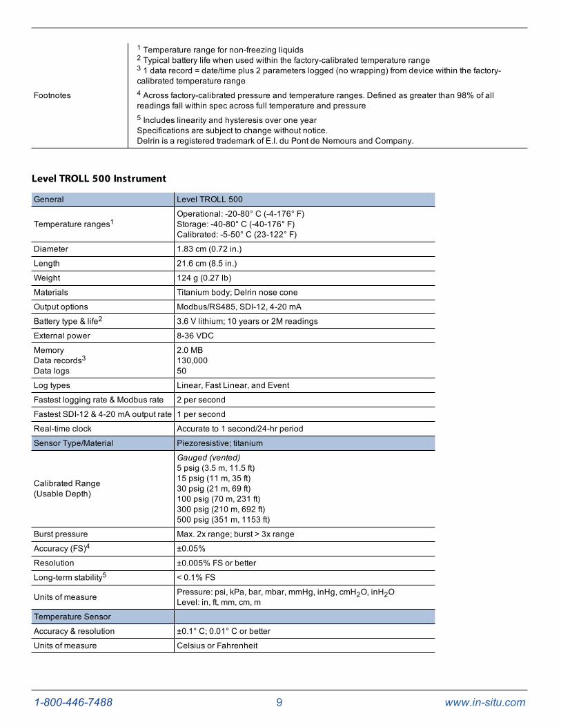
Level TROLL 500 Instrument
General Level TROLL 500
Temperature ranges1Operational: -20-80° C (-4-176° F)Storage: -40-80° C (-40-176° F)Calibrated: -5-50° C (23-122° F)
Diameter 1.83 cm (0.72 in.)
Length 21.6 cm (8.5 in.)
Weight 124 g (0.27 lb)
Materials Titanium body; Delrin nose cone
Output options Modbus/RS485, SDI-12, 4-20 mA
Battery type & life2 3.6 V lithium; 10 years or 2M readings
External power 8-36 VDC
MemoryData records3Data logs
2.0 MB130,00050
Log types Linear, Fast Linear, and Event
Fastest logging rate & Modbus rate 2 per second
Fastest SDI-12 & 4-20 mA output rate 1 per second
Real-time clock Accurate to 1 second/24-hr period
Sensor Type/Material Piezoresistive; titanium
Calibrated Range(Usable Depth)
Gauged (vented)5 psig (3.5 m, 11.5 ft)15 psig (11 m, 35 ft)30 psig (21 m, 69 ft)100 psig (70 m, 231 ft)300 psig (210 m, 692 ft)500 psig (351 m, 1153 ft)
Burst pressure Max. 2x range; burst > 3x range
Accuracy (FS)4 ±0.05%
Resolution ±0.005% FS or better
Long-term stability5 < 0.1% FS
Units of measure Pressure: psi, kPa, bar, mbar, mmHg, inHg, cmH2O, inH2OLevel: in, ft, mm, cm, m
Temperature Sensor
Accuracy & resolution ±0.1° C; 0.01° C or better
Units of measure Celsius or Fahrenheit

1-800-446-7488 10 www.in-situ.com
Warranty 3 yearsExtended warranties are available for all instruments—call for details
Footnotes See See page 8.

1-800-446-7488 11 www.in-situ.com
Level TROLL 700 Instrument
General Level TROLL 700
Temperature ranges1Operational: -20-80° C (-4-176° F)Storage: -40-80° C (-40-176° F)Calibrated: -5-50° C (23-122° F)
Diameter 1.83 cm (0.72 in.)
Length 21.6 cm (8.5 in.)
Weight 124 g (0.27 lb)
Materials Titanium body; Delrin nose cone
Output options Modbus/RS485, SDI-12, 4-20 mA
Battery type & life2 3.6 V lithium; 10 years or 2M readings
External power 8-36 VDC
MemoryData records3Data logs
4.0 MB260,00050
Log types Linear, Fast Linear, Linear Average, Event, Step Linear, True Logarithmic
Fastest logging rate & Modbus rate 4 per second
Fastest SDI-12 & 4-20 mA output rate 1 per second
Real-time clock Accurate to 1 second/24-hr period
Sensor Type/Material Piezoresistive; titanium
Calibrated Range(Usable Depth)
Absolute (non-vented)30 psia (11 m, 35 ft)100 psia (60 m, 197 ft)300 psia (200 m, 658 ft)500 psia (341 m, 1120 ft)1000 psia (693 m, 2273 ft)
Gauged (vented)5 psig (3.5 m, 11.5 ft)15 psig (11 m, 35 ft)30 psig (21 m, 69 ft)100 psig (70 m, 231 ft)300 psig (210 m, 692 ft)500 psig (351 m, 1153 ft)
Burst pressure Max. 2x range; burst > 3x range
Accuracy (FS)4 ±0.05%
Resolution ±0.005% FS or better
Long-term stability5 < 0.1% FS
Units of measure Pressure: psi, kPa, bar, mbar, mmHg, inHg, cmH2O, inH2OLevel: in, ft, mm, cm, m
Temperature Sensor
Accuracy & resolution ±0.1° C; 0.01° C or better
Units of measure Celsius or Fahrenheit
Warranty 3 yearsExtended warranties are available for all instruments—call for details
Footnotes See See page 8.

1-800-446-7488 12 www.in-situ.com
Level TROLL 700H Instrument
Comply with the Office of SurfaceWater by using themost accurate pressure transducer available. The Level TROLL 700Hmeets the surface-water specification of ±0.01 foot.
For accuracy under all operating conditions, instruments are calibrated over the full pressure and temperature range. Eachinstrument includes a serialized, NIST-traceable calibration report.
General Level TROLL 700H
Temperature ranges1Operational: -20-80° C (-4-176° F)Storage: -40-80° C (-40-176° F)Calibrated: 0-40° C (32-104° F)
Diameter 1.83 cm (0.72 in.)
Length 21.6 cm (8.5 in.)
Weight 124 g (0.27 lb)
Materials Titanium body; Delrin nose cone
Output options Modbus/RS485, SDI-12, 4-20 mA
Battery type & life2 3.6 V lithium; 10 years or 2M readings
External power 8-36 VDC
MemoryData records3Data logs
4.0 MB260,00050
Log types Linear, Fast Linear, Linear Average, Event, Step Linear, True Logarithmic
Fastest logging rate & Modbus rate 4 per second
Fastest SDI-12 & 4-20 mA output rate 1 per second
Real-time clock Accurate to 1 second/24-hr period
Pressure Sensor Type/Material Piezoresistive; titanium
Calibrated Range(Usable Depth)
Gauged (vented)15 psig (11 m, 35 ft)
Burst pressure Max. 2x range; burst > 3x range
Accuracy5 ±0.01 foot up to 15 ft and ±0.1% of reading > 15 ft
Resolution ±0.005% FS or better
Units of measure Pressure: psi, kPa, bar, mbar, mmHg, inHg, cmH2O, inH2OLevel: mm, cm, m, in, ft,
Temperature Sensor
Accuracy & resolution ±0.1° C; 0.01° C or better
Units of measure Celsius or Fahrenheit
Warranty 3 yearsExtended warranties are available for all instruments—call for details
Footnotes See See page 8.
1-800-446-7488 13 www.in-situ.com
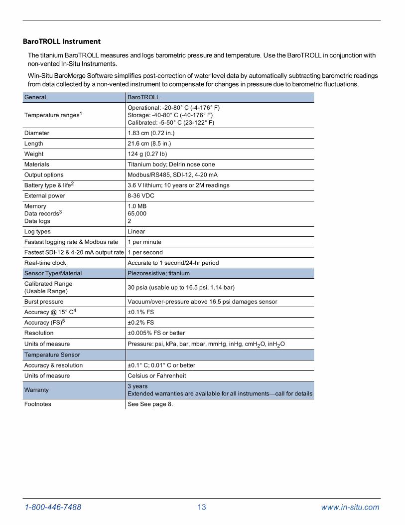
BaroTROLL Instrument
The titanium BaroTROLLmeasures and logs barometric pressure and temperature. Use the BaroTROLL in conjunction withnon-vented In-Situ Instruments.
Win-Situ BaroMerge Software simplifies post-correction of water level data by automatically subtracting barometric readingsfrom data collected by a non-vented instrument to compensate for changes in pressure due to barometric fluctuations.
General BaroTROLL
Temperature ranges1Operational: -20-80° C (-4-176° F)Storage: -40-80° C (-40-176° F)Calibrated: -5-50° C (23-122° F)
Diameter 1.83 cm (0.72 in.)
Length 21.6 cm (8.5 in.)
Weight 124 g (0.27 lb)
Materials Titanium body; Delrin nose cone
Output options Modbus/RS485, SDI-12, 4-20 mA
Battery type & life2 3.6 V lithium; 10 years or 2M readings
External power 8-36 VDC
MemoryData records3Data logs
1.0 MB65,0002
Log types Linear
Fastest logging rate & Modbus rate 1 per minute
Fastest SDI-12 & 4-20 mA output rate 1 per second
Real-time clock Accurate to 1 second/24-hr period
Sensor Type/Material Piezoresistive; titanium
Calibrated Range(Usable Range) 30 psia (usable up to 16.5 psi, 1.14 bar)
Burst pressure Vacuum/over-pressure above 16.5 psi damages sensor
Accuracy @ 15° C4 ±0.1% FS
Accuracy (FS)5 ±0.2% FS
Resolution ±0.005% FS or better
Units of measure Pressure: psi, kPa, bar, mbar, mmHg, inHg, cmH2O, inH2O
Temperature Sensor
Accuracy & resolution ±0.1° C; 0.01° C or better
Units of measure Celsius or Fahrenheit
Warranty 3 yearsExtended warranties are available for all instruments—call for details
Footnotes See See page 8.
1-800-446-7488 14 www.in-situ.com
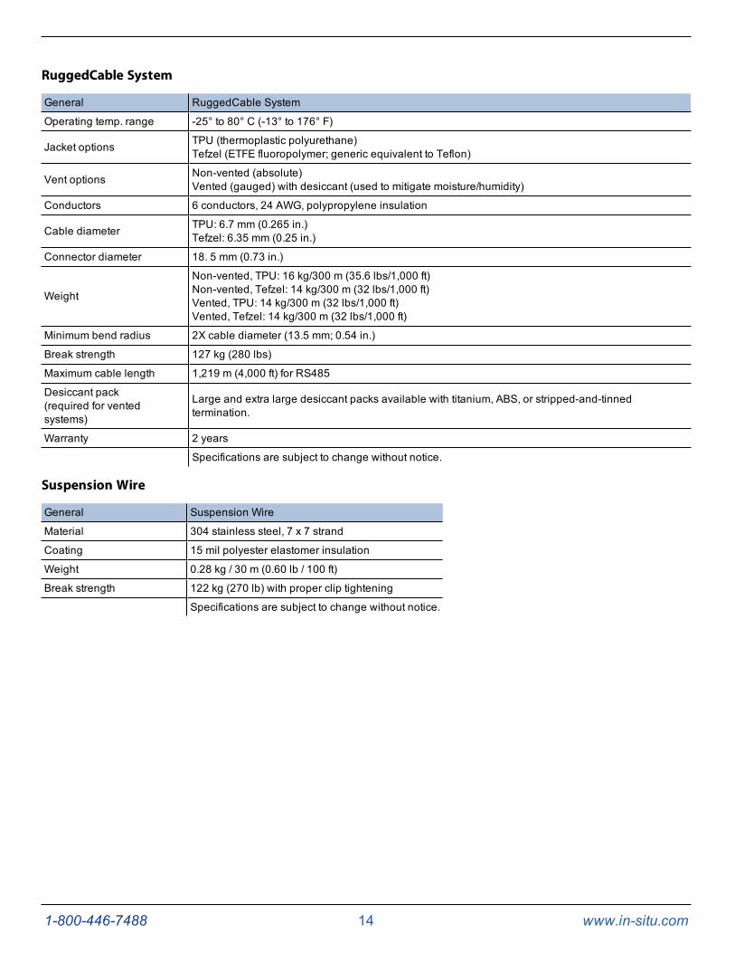
RuggedCable System
General RuggedCable System
Operating temp. range -25° to 80° C (-13° to 176° F)
Jacket options TPU (thermoplastic polyurethane)Tefzel (ETFE fluoropolymer; generic equivalent to Teflon)
Vent options Non-vented (absolute)Vented (gauged) with desiccant (used to mitigate moisture/humidity)
Conductors 6 conductors, 24 AWG, polypropylene insulation
Cable diameter TPU: 6.7 mm (0.265 in.)Tefzel: 6.35 mm (0.25 in.)
Connector diameter 18. 5 mm (0.73 in.)
Weight
Non-vented, TPU: 16 kg/300 m (35.6 lbs/1,000 ft)Non-vented, Tefzel: 14 kg/300 m (32 lbs/1,000 ft)Vented, TPU: 14 kg/300 m (32 lbs/1,000 ft)Vented, Tefzel: 14 kg/300 m (32 lbs/1,000 ft)
Minimum bend radius 2X cable diameter (13.5 mm; 0.54 in.)
Break strength 127 kg (280 lbs)
Maximum cable length 1,219 m (4,000 ft) for RS485
Desiccant pack(required for ventedsystems)
Large and extra large desiccant packs available with titanium, ABS, or stripped-and-tinnedtermination.
Warranty 2 years
Specifications are subject to change without notice.
Suspension Wire
General Suspension Wire
Material 304 stainless steel, 7 x 7 strand
Coating 15 mil polyester elastomer insulation
Weight 0.28 kg / 30 m (0.60 lb / 100 ft)
Break strength 122 kg (270 lb) with proper clip tightening
Specifications are subject to change without notice.

1-800-446-7488 15 www.in-situ.com
About the Pressure/Level Sensor
A pressure transducer senses changes in pressure, measured in force per square unit of surface area, exerted by water orother fluid on an internal media-isolated strain gauge. In-Situ offers instruments with either absolute (non-vented) or gauged(vented) pressure sensors.
The "Absolute vs. Gauged: Comparing Absolute and Gauged Pressure Sensors" technicalnote describes the difference between absolute and gauged pressure sensors and explainsthe proper use of each type of sensor in different applications.
Absolute Pressure Sensor
An absolute or non-vented pressure sensor measures all pressure forces detected by the strain gauge, including atmosphericpressure (PATM). The unit of measure is PSIA (pounds per square inch absolute), measured with respect to zero pressure.The back of an absolute pressure sensor is sealed from the atmosphere. Therefore, the front of the absolute pressure sensorresponds to both atmospheric pressure and the pressure head of water above the sensor.
Absolute Sensor
1 Sensor back
2 Sensor front
3 Water pressure, PW (e.g., 20 PSI)
4 Atmospheric pressure PATM (e.g., 14.5 PSI)
5 Vacuum
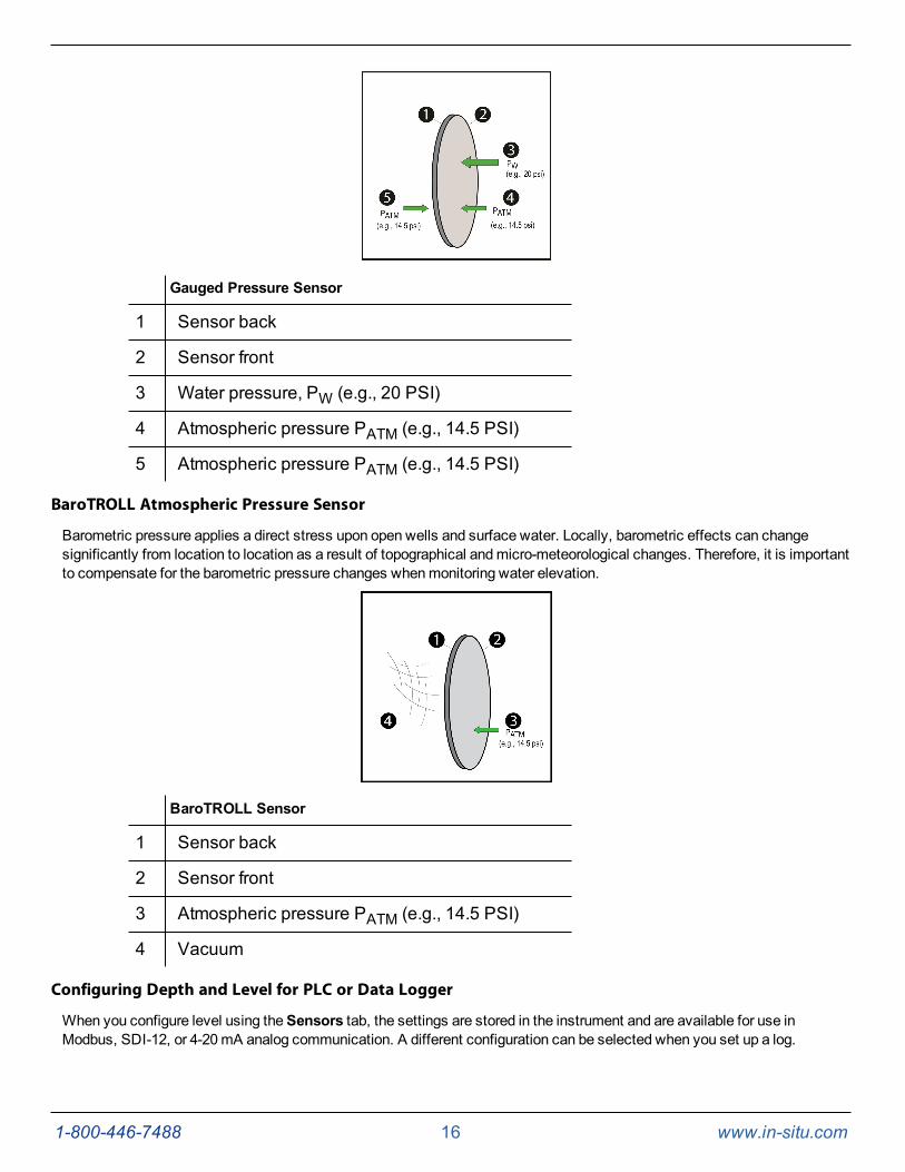
Gauged Pressure Sensor
A gauged or vented pressure sensor eliminates the effects of atmospheric pressure because the vent tube in the cable allowsatmospheric pressure to be applied to the back of the sensor. The unit of measure is PSIG (pounds per square inch gauge),measured with respect to atmospheric pressure.
1-800-446-7488 16 www.in-situ.com
Gauged Pressure Sensor
1 Sensor back
2 Sensor front
3 Water pressure, PW (e.g., 20 PSI)
4 Atmospheric pressure PATM (e.g., 14.5 PSI)
5 Atmospheric pressure PATM (e.g., 14.5 PSI)
BaroTROLL Atmospheric Pressure Sensor
Barometric pressure applies a direct stress upon open wells and surface water. Locally, barometric effects can changesignificantly from location to location as a result of topographical andmicro-meteorological changes. Therefore, it is importantto compensate for the barometric pressure changes whenmonitoring water elevation.
BaroTROLL Sensor
1 Sensor back
2 Sensor front
3 Atmospheric pressure PATM (e.g., 14.5 PSI)
4 Vacuum
Configuring Depth and Level for PLC or Data Logger
When you configure level using theSensors tab, the settings are stored in the instrument and are available for use inModbus, SDI-12, or 4-20mA analog communication. A different configuration can be selected when you set up a log.

1-800-446-7488 17 www.in-situ.com
1. Connect the instrument to the software.
2. Click theSensors tab .
3. Select the level/pressure sensor and click theConfigure button. The Sensor Setup window appears.
4. In theSensor Setupwindow, select the Level parameter, then click Configure The Level SetupWizard opens.
5. In the Level SetupWizard, select the options you want. For more information, view the Help in theWin-Situ 5Software.

1-800-446-7488 18 www.in-situ.com
System Components
Instrument
The Level TROLL Instrument is completely sealed and contains no user-serviceable parts. The instrument includes pressureand temperature sensors, a real-time clock, microprocessor, sealed lithium battery, data logger, andmemory. Optionsinclude a vented or non-vented pressure sensor in a variety of ranges.
RuggedCable System
RuggedCable Systems are custom-built, durable, direct-read cables that include the following items.
l Titanium twist-lock connectors for quick, reliable connections to the instrument, desiccant, and communicationcable
l Metal shield beneath the cable jacket to prevent electrical interferences
l Kellems grip for secure instrument deployment
l Small desiccant for vented systems (for storage only)
Non-vented cables are marked with VF, which means vent free.
Vented or Non-Vented Cable
Vented cable is used with vented pressure sensors to produce gaugedmeasurements. The cable vent tube ensures thatatmospheric pressure is applied to the back of the sensor diaphragm.
Non-vented cable is used with non-vented instruments for absolute measurements. Compensate absolute measurements byusing a BaroTROLL Instrument andWin-Situ BaroMerge Software.
Vented cable is shipped with a small desiccant to protect against condensation. Largerdesiccants are necessary for deployment.
Jacket Options
Tefzel (vented) or thermoplastic polyurethane (TPU, vented or non-vented)
Customizable Cable Lengths
Cables can be ordered up to 1,219m (4,000 ft).
Cable Termination
Cables can be ordered with a twist-lock termination (female connector) on both ends that connect to the instrument, theTROLLCom Communication Device, desiccant, and other accessories.
Cables can also be ordered with stripped-and-tinned termination for wiring to a data logger or controller using SDI-12, analog(4-20mA), or Modbus communication protocol.

1-800-446-7488 19 www.in-situ.com
1 RuggedCable System with female to female connectors2 Stripped-and-tinned RuggedCable System with female connector
3Stripped-and-tinned RuggedCable System with male connector(short length that converts a cable with a twist-lock connector to astripped-and-tinned cable)
1-800-446-7488 20 www.in-situ.com
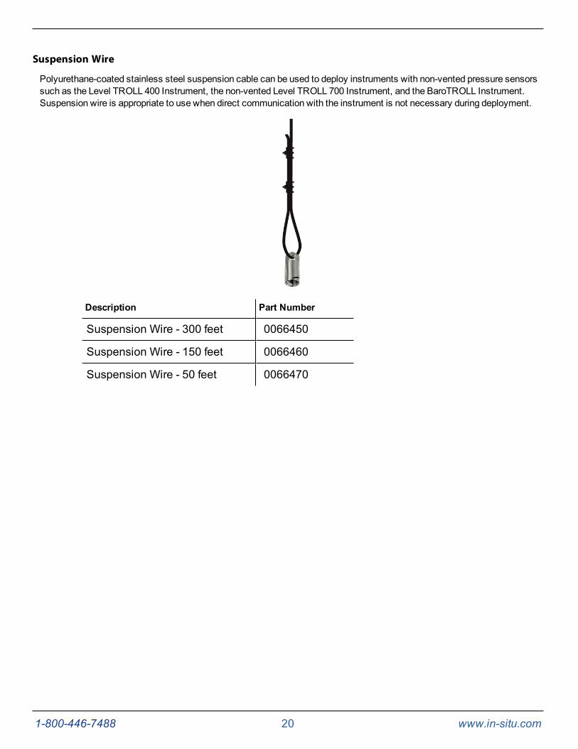
Suspension Wire
Polyurethane-coated stainless steel suspension cable can be used to deploy instruments with non-vented pressure sensorssuch as the Level TROLL 400 Instrument, the non-vented Level TROLL 700 Instrument, and the BaroTROLL Instrument.Suspension wire is appropriate to use when direct communication with the instrument is not necessary during deployment.
Description Part Number
Suspension Wire - 300 feet 0066450
Suspension Wire - 150 feet 0066460
Suspension Wire - 50 feet 0066470

1-800-446-7488 21 www.in-situ.com
Communication Cables
The TROLLCom Communication Device provides an interface between the instrument and a desktop/laptop PC forcalibrating and programming the instrument and for profiling and downloading data. The TROLLCom Communication Deviceis offered in either a cable-connect or direct-connect configuration including a 0.9m (3 ft) vented polyurethane cable, externalpower input jack, and vent with replaceablemembrane.
Description
TheWireless TROLLCom enables wireless communication between a Bluetooth 2.0-enabled Android orWindows deviceand an instrument deployed on a cable. You can also use theWireless TROLLCom as a replacement for a standard wiredTROLLCommunication Device.
TheWireless Rugged TROLL Com permits wireless transmission between a Bluetooth 2.0-enabled device and a RuggedTROLL data logger. Youmust use a Direct Read Rugged TROLL cable with theWireless Rugged TROLLCom.

1-800-446-7488 22 www.in-situ.com
1 Dust cover for the USB connection
2
Connection status
Red (flashing) = The communication device, instrument, and Bluetooth-enabled device are notconnected.
Red (continuous) = The communication device and instrument are connected, but the communicationdevice is not connected to the Bluetooth-enabled device.
-OR-
The communication device is connected via USB cable.
Green (flashing) = The communication device is connected to the Bluetooth-enabled device, but is notconnected to the instrument.
Green (continuous) = The communication device, instrument, and Bluetooth-enabled device areconnected.
3 On/Off button
4
Battery charge status:
100% -90%
90% - 75%
75% - 50%
50% - 25%
Less than 25%
5 Cable connector to the instrument
6 Lanyard connector
7 Serial number
8 USB connection to a power source for charging the internal battery or wired connection to a computer
Contents
l Wireless TROLLCom
l USB cable
l AC wall charger (U.S.A. only, universal charger sold separately)
l Lanyard
Charging the Communication Device
1. Remove the protective cover from the USB slot.
2. Connect the USB cable to the device.
3. Plug the USB cable into the wall charger or a powered USB port such as a computer that has a charger plugged in.
4. The device lights will turn on and blink according to charge level.
A fully-charged communication device will run for up to 40-50 continuous hours.
Battery Tips
The communication device uses an internal, rechargeable Lithium-ion (Li-ion) battery to supply power. While these batterieslast for years with minimal decrease in performance, there are a few tips to prolong the life of the battery.

1-800-446-7488 23 www.in-situ.com
l Avoid full discharges and charge the battery more often between uses.
l Avoid storing the communication device in a high temperature (above 86° F / 30° C) area.
Connecting to a Wireless TROLL Com
AWireless TROLLCom can be used to connect the instrument to software if the sonde is deployed on a cable.
1. Turn on theWireless TROLLCom.
2. Make sure the cable is connected to the instrument as well as the communication device.
3. Go to Bluetooth settings on your mobile device or computer.
4. From the Bluetooth section, search for devices.
5. Tap or click the serial number of the communication device to pair the device with the phone or computer. Theserial number is located under the USB flap.
Connecting to VuSitu
1. Open the VuSitu Mobile App. If you have correctly paired yourWireless TROLLCom with your wireless device,and the instrument is available, the software will connect and display readings.
If the Searching screen continues to show, tap "Choose another device" and select the deviceyou are trying to connect to.
Connecting to Win-Situ 5
1. OpenWin-Situ 5 Software.
2. When prompted, "Connect to device now?" click No.
3. Plug the USB charging cable into the computer andWireless TROLLCom.
4. Click Preferences, then click Comm Settings.
5. Select the correct Com port used by the charging cable, then select the communication settings for the instrumentyou are connecting. The following default communication settings aremost common for In-Situ instruments:
l Baud: 19200
l Data Bits: 8
l Parity Bits: Even
l Stop Bits: 1
l Device Address: 1
l Mode: Modbus-RTU
If you cannot connect using these settings, click the "Search for Devices" or "Reset All Devices" button.
6. Click the checkmark, then click the Connect button in the lower right hand corner.
1-800-446-7488 24 www.in-situ.com
Power Options
Internal Power—Batteries
Internal batteries are not user-replaceable. The approximate percentage of the power remaining in an internal battery isdisplayed on the HomeScreen when an instrument is connected toWin-Situ Software.
The instrument is powered by 3.6 VDC, supplied by a sealed, non-replaceable AA lithium battery. Battery life depends onsampling speed. The battery typically lasts for 10 years or 2,000,000 readings, whichever occurs first.
When an instrument is wired to a data logger or PLC controller, power to the instrument is supplied by the data logger orcontroller.
AC Adapter
The AC adapter provides 24 VDC, 0.75 A, AC input 100-250 V and includes a North American power cord. The TROLLComCommunication Device includes an external power input port for connection to the AC adapter.
Description Part Number
AC Adapter 24 VDC 0052440
Use only In-Situ Inc.'s AC adapter. Damage to the instrument caused by the use of third-party converters is not covered by the warranty.
External Power—External Battery Packs
External battery packs can significantly increase the life of an instrument, either for long-term deployments or to preserve anaging instrument.
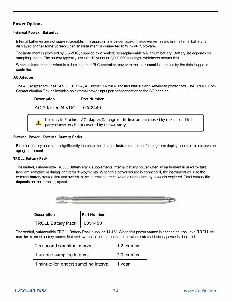
TROLL Battery Pack
The sealed, submersible TROLL Battery Pack supplements internal battery power when an instrument is used for fast,frequent sampling or during long-term deployments. When this power source is connected, the instrument will use theexternal battery source first and switch to the internal batteries when external battery power is depleted. Total battery lifedepends on the sampling speed.
Description Part Number
TROLL Battery Pack 0051450
The sealed, submersible TROLL Battery Pack supplies 14.4 V. When this power source is connected, the Level TROLLwilluse the external battery source first and switch to the internal batteries when external battery power is depleted.
0.5 second sampling interval 1.2 months
1 second sampling interval 2.3 months
1 minute (or longer) sampling interval 1 year

1-800-446-7488 25 www.in-situ.com
TROLL Replaceable Battery Pack
The TROLLReplaceable Battery Pack supplements internal battery power when a Level TROLL or Aqua TROLL 100 or 200Instrument is used for frequent, fast sampling or during long-term deployments. When this power source is connected, theTROLL instrument will use the external battery source first and switch to the internal batteries when external battery power isdepleted. Battery life depends on sampling rate. This battery pack allows for 1.5 V UM-3 or size AA batteries (8) that arereplaced by the user.
The TROLL Replaceable Battery Pack is not submersible.
Description Part Number
TROLL Replaceable BatteryPack 0090000
Estimated Battery Lifetime
TROLL Battery Pack Level TROLL Family
15 minute loggingrate* 1.1 years
1 hour logging rate* 1.1 years
*Logging with all sensors. Actual battery lifetime varies based on site conditions.
TROLL ReplaceableBattery Pack Level TROLL Family
15 minute loggingrate* 1.6 years
1 hour logging rate* 1.7 years
*Logging with all sensors. Actual battery lifetime varies based on site conditions.
1-800-446-7488 26 www.in-situ.com
Installation Accessories
NPT Adapter
The 0.25 in. NPT adapter allows instrument installation in piping.
Part Number Image Description
0051470 NPT Adapter
Cable Extender
The cable extender connects two lengths of RuggedCable System tomeet varying installation needs.
Description Image Part Number
Cable Extender 0051490
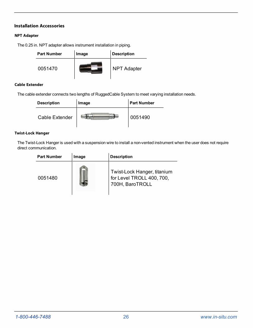
Twist-Lock Hanger
The Twist-Lock Hanger is used with a suspension wire to install a non-vented instrument when the user does not requiredirect communication.
Part Number Image Description
0051480Twist-Lock Hanger, titaniumfor Level TROLL 400, 700,700H, BaroTROLL
1-800-446-7488 27 www.in-situ.com
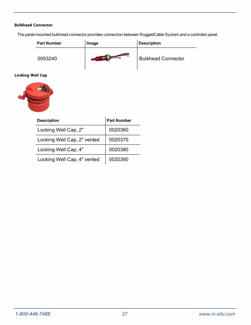
Bulkhead Connector
The panel-mounted bulkhead connector provides connection between RuggedCable System and a controller panel.
Part Number Image Description
0053240 Bulkhead Connector
Locking Well Cap
Description Part Number
Locking Well Cap, 2" 0020360
Locking Well Cap, 2" vented 0020370
Locking Well Cap, 4" 0020380
Locking Well Cap, 4" vented 0020390

1-800-446-7488 28 www.in-situ.com
Well Dock Installation Ring
The well dock installation ring provides installation support for 2", 4", and 6" well casings.
Description Part Number
Well Dock Installation Ring 2" 0004690
Well Dock Installation Ring 4" 0004700
Well Dock Installation Ring 6" 0020650
Software
TheLevel TROLL can be programmed using the VuSitu Mobile App for Android, or usingWin-Situ 5 Software.
About VuSitu
VuSitu is themobile user interface and control application for In-Situ water quality instruments. You can use VuSitu onmobiledevices with Android operating system 4.4, Bluetooth 2.0 and newer. Download the latest version of the app from theGooglePlay Store at play.google.com.
VuSitu allows you to accomplish the following tasks.
l View live readings that update every 10 seconds
l Change parameters and units
l Set up a data log
l Record data
l Email data in spreadsheet format
l Download data tomobile device
l Transfer data frommobile device to a computer

1-800-446-7488 29 www.in-situ.com
l Organize data by Location
l Calibrate Sensors and View Reports
Connecting Your Instrument to VuSitu
To use VuSitu, you will need a Bluetooth-enabledmobile device, aWireless TROLL Com and a deployment cable.
Attach one end of the cable to theWireless TROLL Com and secure the other end to the instrument. Press the power buttonon theWireless TROLL Com and open the VuSitu mobile app on your phone or tablet.
VuSitu will automatically search for Bluetooth devices nearby, but you will need to select the correct instrument whenconnecting for the first time. Select Choose or Add a Device. You should see the serial number of the instrument you wishto pair. Tap the serial number to connect. Tap theBack button on your device to view the Connected Instrument screen.

1-800-446-7488 30 www.in-situ.com
Selecting with Long-press and Swipe
Long Press Swipe Left Swipe Right
Press and hold any item in a list offiles. You can now select multiple files.
Press an item and swipe left to revealthe delete and share icons.
Press any item in a list and swipe rightto reveal the sharing icon.

1-800-446-7488 31 www.in-situ.com
Taking live readings in VuSitu
Snapshot Mode Live Readings Mode
Take a single readingand save to Snapshot file.
View Snapshot file fromMenu > Data Files.
Check Snapshot option.
Take readings at two-second intervals.
View readings fromMenu > Data Files.
Check Live option.

1-800-446-7488 32 www.in-situ.com
Setting Up a Log
From the ConnectedInstrument screen, selectLogging.
TapNew Log and follow theprompts to create a name,select a location and choosethe parameters you wish tomonitor.
Select a level mode in step 4.Tap the blue circle to the rightof each option for anexplanation of how themodeworks.
For Depth toWater andSurface Elevationmodes,enter a level reference. See"About the Level Reference"on page 55 of this manual forcomplete information aboutlevel modes and levelreferences.
Downloading and sharing your data.
You can download VuSitu data as an HTML file and share it via email, SMS or a cloud storage service such as Google Drive.To download a log, select it from the Downloaded Data screen and tapSave to.
Choose one of the download options from themenu. You can transfer a data file from your mobile device to a PC viaBluetooth, email it to yourself or any valid email address, save the file to the VuSitu folder on your device or upload it toGoogle Drive.

1-800-446-7488 33 www.in-situ.com
View your data in any web browser by double-clicking the file. You can then export a CSV file by clicking theExport a CSVlink at the top of the page.
Getting Started
This section provides an overview of the initial steps necessary to prepare the instrument to log data.
l Select the appropriate TROLLCom Communication Device. This determines the hardware connections, andmayinfluence the software installation. The drawing on the following page shows the function of the different TROLLCom Communication Devicemodels.
l Install the software.
l Connect the hardware.
l Open the software and establish communication with the instrument.
Select a TROLL Com Communication Device
The subsequent figure shows the function and connection features of the TROLLCom Communication Devicemodels.
l A Direct-Connect TROLLCommight be preferred for programming an instrument that will be deployed on asuspension cable.
l A RuggedCable System and a Cable-Connect TROLLCom are required if you intend to communicate with theinstrument while it is deployed. However, you can program the instrument with any TROLLCom.
l AWireless TROLL Com will allow you to connect to the VuSitu mobile app, which you can use to configure anddeploy your instrument.

1-800-446-7488 34 www.in-situ.com
1 Cable-Connect TROLL Com Communication Device, serialconnection, for field use
2 Direct-Connect TROLL Com Communication Device, serialconnection, programming only, not submersible
3 USB port on a PC/laptop
4 Direct-Connect TROLL Com Communication Device, USBconnection, programming only, not submersible
5 Cable-Connect TROLL Com Communication Device, USBconnection, for field use

1-800-446-7488 35 www.in-situ.com
Connecting RuggedCable
Connect the Instrument to the RuggedCable
1. Remove the protective caps from the instrument and cable. Ensure that the O-ring on the instrument connector isclean. Apply a small amount of vacuum grease to the o-ring.
2. Position the instrument and cable flat edges so they will connect properly. Insert the instrument connector firmlyinto the cable connector.
3. Hold the textured section of the sleeve in one hand and the instrument in the other. Push and twist until you hear aclick. The click ensures the cable and instrument are securely attached.
Connect TROLL Com Communication Device to the RuggedCable System
1. If a desiccant is present, remove the desiccant from the cable. Twist the desiccant and cable sleeve in oppositedirections to unlock the desiccant from the cable.
2. Position the TROLLCom and cable flat edges so they will connect properly. Push and twist until you hear a click.

1-800-446-7488 36 www.in-situ.com
Install the Software
Win-Situ 5 Software
Install Win-Situ 5 Software from the In-Situ software/resource CD or from the In-Situ website. Click theWin-Situ 5 link, andfollow the instructions to install Win-Situ 5 to your local hard drive.
USB TROLL Com Drivers
If you are using a USB TROLLCom Communication Device, be sure to select the option "Install USB TROLLCom Drivers"during theWin-Situ 5 installation. Two drivers will be loaded to your hard drive, one for the USB TROLLCom, one for theUSB TROLLCom serial port.
1-800-446-7488 37 www.in-situ.com
Field Deployment
Program the Instrument
In order to set up a log or download data, youmust connect the instrument to a computer runningWin-Situ 5 software or to amobile device with the VuSitu app. See page 52.
Position the Instrument
Place the instrument at the desired depth. Position the instrument below the lowest anticipated water level, but not so lowthat the pressure sensor rangemight be exceeded at the highest anticipated water level. Refer to the tables below todetermine usable depth.
A BaroTROLL Instrument can be deployed with a non-vented instrument to compensatelevel data for changes in atmospheric pressure. Make sure the clocks on both instrumentsare synchronized, and install the BaroTROLL in a location that will never be submerged inwater. See page 41.
Range Effective Range Usable Depth
PSIA PSIA kPA Meters Feet
30 15.5 106.9 11 35
100 85.5 589.5 60 197
300 285.5 1968 200 658
500 485.5 3347 341 1120
1000 985.5 6795 693 2273
* Effective range for psia sensors is limited by an estimated 14.5 PSIatmospheric pressure at sea level.
Non-Vented Level TROLL Instrument
Range Usable Depth
PSIG kPA Meters Feet
5 34.5 3.5 11.5
15 103.4 11 35
30 206.8 21 69
Vented Level TROLL Instrument

1-800-446-7488 38 www.in-situ.com
Range Usable Depth
100 689.5 70 231
300 2068 210 692
500 3447 351 1153
Verify Instrument Depth
After you have installed the instrument, it is possible to connect the instrument to a computer or mobile device, open thesoftware, and take a reading to verify the installation position. If the reading confirms that the instrument is in the correctposition, you can secure it as described below.
During log setup there was an option to "RemindMe Later" for setting a level reference. If you set the log to remind you later,ensure that the instrument is submerged and set the level reference when prompted. See page 55.
Secure the Cable
The RuggedCable System includes a Kellems grip near the up-hole end. You can compress the wiremesh and slide the gripto the desired location on the cable. Pull on the grip to tighten it on the cable.
Use the loop on the Kellems grip to anchor the cable to a convenient stationary object such as the In-Situ well dockinstallation ring. To install the Kellems grip to the installation ring, insert the loop into the locking clip on the well dock andposition the assembly at the top of a well casing.
1 Well Dock Installation Ring
2 Kellems Grip
3 Instrument Installed in Well

1-800-446-7488 39 www.in-situ.com
Install the Desiccant
Vented cable must be protected with a desiccant pack that is properly sized for siteconditions.
Desiccant
Desiccant protects cables, connections, and internal components from condensation, which can cause irreparable damageand loss of data. Indicating desiccant changes from blue to pink as it becomes saturated with moisture.
Desiccant stages (from left)New, nearly expired (replace now), expired
It is extremely important to use a properly-sized desiccant for your deployment and to change desiccant often. Desiccantshould be changed before the entire volume has turned pink, and you should use enough desiccant to effectively keep yourequipment dry until your next scheduledmaintenance. Desiccant longevity is dependent on site conditions and can vary fromone site to the next.
Installation Guidelines
l Never let the instrument fall freely down awell. Doing so will damage the sensor.
l After you have installed the instrument, verify the water level reading. Move the instrument and take anotherreading to ensure that the instrument shows reasonable change. The instrument could be wedged against the wellcasing with a loop of cable hanging below. An instrument in such a position could become dislodged andmovewhile it is logging data, which would record a false change in the water level.
l For accuratemeasurements, the instrument should remain immobile while it is logging data.
l Make sure that the uphole cable end is protected. The vented cablemust be protected with a desiccant, and thenon-vented cablemust be protected with a dust cap. The uphole cable endmust be positioned above the highestanticipated water level. Avoid placing this end in a location that might flood.
l Do not deploy instruments in such a way that icemay form on or near the sensor or cable connections. Iceformation is a powerful expansive force that can over-pressurize the sensor or otherwise cause damage. Damageassociated with ice formation is not covered by the instrument warranty.
l Do not allow vented cable to bend enough to obstruct the internal vent tube. The recommended bend radius is 13.5mm (0.54 in), which is twice the cable diameter.

1-800-446-7488 40 www.in-situ.com
R Bend radius 13.5 mm (0.54 in)D Cable diameter
Stabilization Time
After you have installed the instrument, allow it to stabilize to the environment for about 10minutes before logging data. TheT95 response time for temperature is less than 9minutes.
A generous stabilization time is always desirable, especially in long-term deployments. Even though the cable is shielded,temperature stabilization, stretching, and relaxing can cause changes to readings.
If you intend to monitor water levels to the instrument's stringent accuracy specifications,allow up to 60 minutes for the probe and cable to stabilize to the environment.

1-800-446-7488 41 www.in-situ.com
BaroTROLL Instrument Installation
The BaroTROLL Instrument is designed to log barometric pressure from 0 to 16.5 PSIA (1.14 bar, 33.59 inHg) at the surfacenear a submerged non-vented Level TROLL Instrument or Aqua TROLL 200 Instrument. BaroTROLL datamay then be usedto correct the water level data for barometric pressure fluctuations. See page 15.
Programming the Baro TROLL Instrument
Connect the BaroTROLL toWin-Situ 5 software or the VuSitu mobile app and sync the clock.See page 53.
Set up a log with the same start time and sample interval as you set up in the non-vented level instrument. See page 54.
Installation
After the BaroTROLL Instrument is programmed, install it in a protected location above the water level near the submergedwater level instrument. One installation configuration option is shown below using a twist-lock hanger and a suspension wire.
To prevent flooding of the BaroTROLL electronics, attach the twist-lock hanger before youinstall the BaroTROLL. Do not submerge the Baro TROLL Instrument.

1-800-446-7488 42 www.in-situ.com
1 Atmospheric pressure + water pressure (as measured by a non-ventedpressure sensor)
2 Atmospheric pressure (as measured by the BaroTROLL)
3 Water pressure (as measured by a vented pressure sensor, or bysubtracting BaroTROLL data from non-vented pressure sensor data)
4 BaroTROLL Instrument (Do not submerge.)5 Non-vented Level TROLL Instrument
To merge atmospheric pressure data with water level data, See page 59.

1-800-446-7488 43 www.in-situ.com
Win-Situ Overview
Data Tab
When you openWin-Situ 5 Software, theData tab appears. The left side of the screen contains a file tree where you can viewpreviously downloaded site data as well as data you have exported toMicrosoft Office Excel. The links on the right side ofthe screen show where downloaded data are stored on your computer. The disconnected plug icon in the lower-right corner ofthe screen indicates that the software is not yet communicating with an instrument.
Screen Element Definition
The disconnected plug indicates the instrument is notcommunicating with the software. Click to establish communicationwith a connected instrument.
The connected plug indicates the instrument is communicatingwith the software. Click to disconnect the software from theinstrument.
The Home tab displays real-time readings from the instrument.When connection to the instrument is first established, the softwaredisplays one reading of all available parameters in light gray.You must click the Play button at the bottom of the screento view real-time readings.
The Logging tab displays a list of logs stored in the connectedinstrument. When you click the Logging tab, it can take a momentfor the software to retrieve information from the instrument. (Notapplicable for the RDO PRO-X and the Aqua TROLL 400.)

1-800-446-7488 44 www.in-situ.com
Screen Element Definition
The Sensors tab lists the sensors in the connected instrument,along with their serial numbers and the dates of factory calibrationand user calibration. Use the buttons in this tab to calibratesensors that support user calibration and configure sensors thatare supported by the instrument.
The Device Setup tab allows access to instrument information andsettings such as instrument name, serial number, firmware version,communication settings, diagnostics, and factory reset options.
1-800-446-7488 45 www.in-situ.com
Home Tab
TheHome tab displays real-time readings from a connected instrument. When you first establish communication, thesoftware displays one reading of all available parameters in light gray.
Screen Element Definition
The Sites button allows you to add, edit, or delete a site. Click thedrop-down arrow next to the button to view the list of sites.
The Device Memory gauge turns yellow when the internal memoryis used. Note: Non-logging instruments do not have internalmemory, however, the gauge shows 100 percent green when poweris applied.
The Device Battery gauge turns yellow as the battery is depleted.This example shows 80 percent of the battery remaining (green) and20 percent used (yellow). Note: Non-logging instruments do nothave internal batteries, however, the gauge shows 100 percentgreen when power is applied.

1-800-446-7488 46 www.in-situ.com
Screen Element Definition
The Logging Status icon:Green—The instrument is actively logging data.
Gray—The instrument has no logs pending or running. Non-logging instruments always show a gray status icon.
Yellow—The instrument has log data that was collectedaccording to specific instructions in the "Pending" or"Suspended" state.
The Alarm icon provides additional instrument statusinformation.
Green—No alarms or warnings
Yellow—One or more warnings
Red—One or more alarms
Move the cursor over the alarm icon to view a description.Click the Device Setup tab for detailed information on thealarm or warning.
Note: Disregard the Device Reset alarm for non-logginginstruments such as the RDO PRO Probe or the Aqua TROLL400.
System Time is displayed on the left. Device Time is displayed onthe right. Clocks are updated once every two seconds. When theDevice Time is displayed in red, it differs from the current SystemTime, and should be synchronized.
The Time Sync button is used to write the current PC time to theinstrument. If you need to set the instrument clock to a time otherthan the system (PC) time, use the Set Clock button on the DeviceSetup tab.
Meter View shows the last known parameter values, displayed withcurrent units and time stamp. Readings are sized to occupy theentire screen. This is the default display in the Home tab. If the typeis black, the readings are updating in real time.
List View is a running list of the most recent records. New readingsare continuously added to the top of the list and old readings scrolloff the bottom.
Graph View shows a real-time trend graph of the selectedparameters.

1-800-446-7488 47 www.in-situ.com
Screen Element Definition
The Snapshot button records one set of readings.
The Record button logs data to a CSV file that can be opened in aspreadsheet program. This is not the same as recording data in alog on the instrument.

1-800-446-7488 48 www.in-situ.com
Logging Tab
The Logging tab displays a list of logs in the instrument. When you click the Logging tab, it may take amoment for thesoftware to retrieve information from the instrument.
Log InformationColumns across the Logging screen show information about the logs in the instrument.
l Symbol—This is a graphic representation of the information in theStatus column.
l Site—The site that was specified when the log was configured.
l Log Name—The name that was entered when the log was configured.
l Type—The loggingmethod that was selected when the log was configured.
l Start Time—For a Pending log, the scheduled start time is shown. For a Ready log that has not yet started, thiscolumn displays “Manual.” For a Running or Stopped log, the actual start time is shown.
l Scheduled Stop Time—For a log with a scheduled stop, the scheduled stop time is shown. For a log without ascheduled stop time, this column is blank.
l Stop Time—For a Pending or Ready log, this column is blank. For a Running log, the time of the last data point isshown. For a Stopped log, the actual stop time is shown.
l Status—Each log has a specific status. See Log Status for details.
l Used Size—Kilobytes of instrument memory allocated for this log. For a Pending or Ready log, the current size ofthe log configuration is shown. For a Completed log, the size of the entire log file is shown. For a Running log, thecurrent size of the log up to the last data point is shown.
Log StatusThe status of each log in the instrument is displayed in the Logging tab by a symbol beside the log name, and in the Statuscolumn.
Ready—Manual Start log is ready to start.

1-800-446-7488 49 www.in-situ.com
Pending—Scheduled start log is ready to start at its programmed time, or when you click theStart button.
Running—The log is actively logging data.
Suspended—The log has been paused (stopped temporarily).
Stopped—The log has been stopped, either manually or on a schedule.
Deleted—The log has beenmarked for deletion and will be deleted from the instrument whenmemory is needed. Thesoftwaremanages this automatically.
Invalid—The log as programmed cannot be run.
Ready, Pending, Running, and Suspended logs are considered active. Only one log canbe active in the instrument.
Log Control ButtonsYou can control the status of a log by selecting the log and clicking the appropriate button in the Logging tab control panel:
TheStart button starts aReady orPending log, or resumes aSuspended log.
ThePause button pauses aRunning log allowing you the option to resume it.
TheRestart button restarts the selectedRunning log from the beginning. This can be useful during aquifer testing usinga logarithmic data collection schedule.
TheStop button permanently stops the selectedRunning log.
Log OperationsUse the buttons in the control panel to perform the following actions:
Create a new log.
TheNew button is disabled if a Ready, Pending, Running, or Suspended log is on the instrument. When the instrumentcontains its maximum number of logs, the New button is unavailable.
Edit (or review) the log configuration for a Ready, Pending, or Invalid log.
Delete the log. (Note that youmust delete a log twice before it is permanently removed.)
Download the log to a PC.

1-800-446-7488 50 www.in-situ.com
Sensors Tab
TheSensors tab lists the sensors in the instrument, along with their serial numbers and calibration dates. Use the buttons inthis tab to calibrate and configure sensors.
CalibrateUse theCalibration button to calibrate sensors or to adjust a level reference that is currently stored on the instrument. TheCalibrate button is not available when the instrument does not support calibration (e.g. BaroTROLL Instrument).
1. With the instrument connected to the software, select theSensors tab.
2. Select the parameter you intend to calibrate.
3. Click theCalibrate button .
ConfigureUse theConfigure button to select parameter units and to configure parameters that support configuration. Examplesinclude Level/Depth, Specific Conductivity, and Total Dissolved Solids. Parameters cannot be configured while theinstrument is showing live data on theHome screen or while the instrument contains an active log.
1. With the instrument connected to the software, select theSensors tab.
2. Select the parameter you intend to configure.
3. Click theConfigure button .
When you configure the Level parameter using the Sensors tab, the settings are stored inthe instrument and are available for use in Modbus, SDI-12, or analog communication (ifavailable). If desired, a different configuration can be selected when setting up a log.
Device Setup Tab
In general, you should not use theDevice Setup tab unless you are corresponding with the In-Situ technical support team.However, you can use this screen to set up communication protocols if you are connecting the instrument to a PLC or datalogger.

1-800-446-7488 51 www.in-situ.com
See the online Help for more details.

1-800-446-7488 52 www.in-situ.com
Using Win-Situ 5 Software
Connecting an Instrument to the Software
When you openWin-Situ 5 Software, you are asked if you want to connect to your device. Click Yes. Synchronize theinstrument clock to the PC clock.
The software displays an error message if a connection cannot be established.
Selecting the Correct COM Port
If you are using a USB TROLLCom, select the correct COM port by following the steps below. If you are using a serialTROLLCom, theWin-Situ Software should default to the correct COM port, which is usually COM 1.
Steps for Windows 8.1 and Windows 10 systems.
1. Right-click theStart button.
2. Click Device Manager.
3. Click the arrow next toPorts (COM and LPT), and locate the USB Serial Port listing. The number listed next tothis entry is your COM port address.
Steps for Windows 8 systems.
1. Right-click theStart screen.
2. Select All Apps.
3. Click Control Panel.
4. Open theDevice Manager.
5. Click the arrow next toPorts (Com and LPT), and locate the USB Serial Port listing. The number listed next tothis entry is your COM port address.
Steps for Windows 7 systems.
1. Click theStart button, and open theControl Panel.
2. Click Hardware and Sound, and open theDevice Manager.
3. Click the arrow next toPorts (COM and LPT), and locate the USB Serial Port listing. The number listed next tothis entry is your COM port address.
Steps for Windows XP systems.
1. Click theStart button, and open theControl Panel.
2. Double-click theSystem icon. Click theHardware tab, and open theDevice Manager.
3. Click the plus sign next toPorts (COM and LPT), and locate the USB Serial Port listing. The number listed next tothis entry is your COM port address.
The following steps apply for all Windows operating systems.
1. Once you have determined the correct COM port address in your operating system, reopenWin-Situ 5 Software.
2. Close any open windows inWin-Situ Software.
3. Click Preferences.
4. Click Comm Settings, and then click thePort Numbermenu.

1-800-446-7488 53 www.in-situ.com
5. Scroll down to find the correct COM port address. Click the check mark to accept the changes.
6. Click the yellow Connect button in the lower right corner to establish a connection to the instrument.
Bluetooth & Wireless TROLL Com
Connect the cable to theWireless TROLLCom and the Level TROLL instrument. Turn on theWireless TROLLCom andopenWin-Situ 5. Choose File > Connect to access the Default Communication Settings window.
Select the radio button labeledBluetooth Communications and click Configure Bluetooth Devices. You will see a list ofnearby Bluetooth devices. Click theWireless TROLLCom you are using and click the check mark.
Finally, click the yellow Connect button at the bottom right of the screen to complete the connection.
Setting the Instrument Time
The instrument time and the current PC time are shown at the top of the screen when an instrument is connected to thesoftware.
The PC time appears on the left, the instrument time on the right. Both clocks are updated at 0.5 Hz (once every twoseconds). The device time is displayed in red if it differs by more than a few seconds from the current PC time. Data loggingschedules depend on a correct instrument time.

1-800-446-7488 54 www.in-situ.com
To synchronize the instrument time to the current PC time, click theClock Sync button . Win-Situ writes the currentPC time to the instrument.
Adding a New Site
To add a new site to the site database in your working directory do one of the following:
On theData tab, click theSite Data folder, select File> New > Site.
or
On theHome tab, click theSite button to display the site list, then click New . Enter a name for the site. This is the onlyrequired field.
Click Save to save the new site. The new site will appear in theSite Data folder, andWin-Situ will add it to the site databasein the working directory on your computer. It is now available to select for any instrument log.
Log Setup
The Log SetupWizard presents sequential screens to help you supply all the information necessary to set up a data log in theinstrument.
To access the Log SetupWizard the instrument must be connected to the software.
1. Click the Logging tab .
2. Click theNew button .
TheNew buttonmay be disabled or may show awarning if an active log already exists on theinstrument, or if the instrument is polling live data (see theHome screen), or if the devicealready contains its maximum number of logs.
3. Select theSitewhere the set of data will be logged and supply a name for the log.
4. Click the right arrow to continue after each step.
5. Select the parameters you intend tomeasure, choose themeasurement units, and specify the order in which theselected parameters will be logged.
6. Select the loggingmethod you intend to use. See page 54.
7. Select the log interval. A log interval is how often ameasurement will be taken and stored.
8. Select the start condition, stop condition, and specify how to handle full devicememory.
9. If you selected Level orDepth as a parameter to measure, specify how you intend to log this parameter. See page55.
10. The final screen summarizes the log setup. Click the check mark to write this information to the instrument.
Logging Method Descriptions
The following is a list of log types and their descriptions. The log types that are available on an instrument vary dependingupon the capabilities of the instrument.
Logging Methods for Long-Term Monitoring
Linear
Linear log typemeasures and records at a user-defined fixed interval of oneminute or more. This method is used for long-termstudies, landfill monitoring, stream gauging, tidal studies, and backgroundmonitoring prior to aquifer testing. Intervals aremeasured in days, hours, or minutes.

1-800-446-7488 55 www.in-situ.com
Linear Average
Linear Average log type can smooth out anomalous highs and lows that may occur in a data set, for example, when a waterwave passes over the instrument. Each storedmeasurement is the average of several rapid measurements. This method isused for long-term studies, stream gauging, tidal and open-water studies where trends aremore important than accuracy.Intervals aremeasured in days, hours, minutes, or seconds.
Event
Linear Event log type combines basic fixed-interval logging of specified parameters with the ability to log data at a fasterinterval when a single-parameter event condition is present.
Logging Methods for Aquifer Testing
True Logarithmic
True Logarithmic log type captures early-time water-level data during aquifer testing. Measurements are very closely spacedat the start of the test (4 measurements per second) andmove further apart on a logarithmically decaying schedule as thetest progresses. There are 40measurements per log decade. This log type is commonly used for rapid step-drawdown pumptests, constant-rate pump tests, and slug tests.
Fast Linear
Fast Linear log typemeasures and records at a user-defined fixed interval of oneminute or less. The interval is small(seconds, milliseconds), and the test is usually of short duration due to the volume of data logged and the impact of very fastsampling on battery life.
Step Linear
Step Linear log typemeasures and records data according to a number of user-defined elapsed time intervals or "steps"within a schedule. Both the elapsed time and the number of measurements within each step can vary. After completing theelapsed time for each step, the schedule will automatically move to the next step. Up to 10 separate steps can be defined.
About the Level Reference
A Level Reference, also called an offset, is a user-specified starting point for logged Level readings.
Depthmode does not require that you enter a Level Reference.
The Level Reference can be any value you choose. Here are some examples:
l Elevation—If you calculate the water level abovemean sea level (MSL) and enter this as the Level Reference,then elevations aboveMSLwill be logged.
l Depth to Water—If youmeasure the depth to the water surface (DTW) from the top of the well casing and enterthis as the Level Reference, then DTW (also called drawdown) values will be logged.
l Zero—A Level Reference of 0 effectively sets the probe to zero at the start of the log. Changes, both positive andnegative, from the starting water level, will be logged.
Once you have determined the value of your Level Reference, the software gives you three options for entering it. Thesecontrol when the level reference is applied.
l New Reference—This option is designed to be used with an active software connection when the device isinstalled in the water.
1-800-446-7488 56 www.in-situ.com
A new level reference must be entered while the device's pressure sensor issubmerged in its final position in the water. This is because the current probereading is set equal to the Level Reference to create the offset that takes effect at the startof the data log. The log header will show the probe reading at the time you entered theLevel Reference.
During log setup, the software presents two additional options for entering the Level Reference:
l Set first logged reading—Use this option when the instrument will be deployed on wire rather than cablebecause you will not be able to communicate with the instrument when it is submerged.
l Remind me to set reference later—Use this option to defer the entry of the Level Reference during log setup andset a reminder to enter it when the device is submerged in its final position.
Starting a Log
Every log is programmed for either amanual or a scheduled start. A log with amanual start time is displayed in the Loggingscreen withReady in theStatus column. A log with a scheduled start time is displayed withPending in theStatus column.
Starting a Pending Log
A Pending log automatically starts at the scheduled time without any user intervention.
A scheduled log with Pending status can be manually started at any time before itsscheduled start.
Starting a Manual Log
With the instrument connected to the software, select the Logging tab.
Select the Ready log you want to start.
Click theStart Log button . The log starts and the symbol changes. TheStatus column displays Running.
Suspending (Pausing) a Log
A running logmay be temporarily paused. For example, youmight want to reposition an instrument, calibrate a sensor, orclean a sensor and later resume the log. A log can be suspended and resumed three times.
1. With the instrument connected to the software, select the Logging tab .
2. Select the log you intend to suspend.
3. Click theSuspend button . Suspended appears in theStatus column.
Resuming a Suspended Log
1. To resume logging after a log has been suspended, select the Logging tab.
2. Select theSuspended log.
3. Click theStart Log button . Logging resumes. Running appears in theStatus column. The data file willshow the time when the log was suspended and the time when it restarted.

1-800-446-7488 57 www.in-situ.com
Stopping a Log
A log can bemanually stopped at any time, even if a stop time has been previously scheduled. If you did not specify a stopcondition when you defined the log, the log will run until the instrument is out of memory or battery power, or until youmanually stop it.
A log that has been stopped cannot be resumed. If you intend to resume a log later, youshould suspend a log rather than stop it.
1. Tomanually stop a log, the instrument must be connected to the software.
2. Select the Logging tab .
3. Select the running log you intend to stop.
4. Click theStop Log button .
Downloading Data to a PC
This procedure copies the data log from the instrument to a PC. It does not remove the data log from the instrument. After alog is downloaded, it can be exported to a CSV file format that can be used by spreadsheet programs. The time shown in thelog name is the time the log was downloaded.
1. With an instrument connected, select the Logging tab .
2. Select the log you intend to download.
3. Choose a Running, Suspended, Stopped, or Deleted log.
4. Click theDownload button.
5. In the next screen, select one of the three download options.
l All data
l New data (data logged since the last download)
l Time interval to download
New data is downloaded by default to a new log file. To append new data to the last download ofthis log, be sure the option "Append logs on download" is selected in theGeneral Settingsdialog (Preferences > General Settings).
2. The log is copied to the connected PC into yourWin-Situ working directory folder. View or change the workingdirectory using File > Settings.
3. At the end of the download, Win-Situ gives you the option of viewing the data.
l Select Yes and the log is displayed in theData screen.
l Select No and the Logging screen appears. You can view the data at any time by selecting it in theDatatab.
Viewing Logged Data
1. To view the data stored in the instrument, youmust first download the data. A connection to an instrument is notneeded after the data log has been downloaded.
2. Select theData tab .
1-800-446-7488 58 www.in-situ.com
3. On the left side of the screen, select the log you want to view. To expand a folder shown in the navigation tree,double-click the folder. The content of the data log is displayed on the right side of the screen in text or graphformat.
To switch between view formats, click the Text or the Graph button in the control panel.To customize the text or graph view, select Preferences > Graph Settings orPreferences > Data View Settings. These options apply to all downloaded data untilyou change the options.
Importing VuSitu Data to Win-Situ
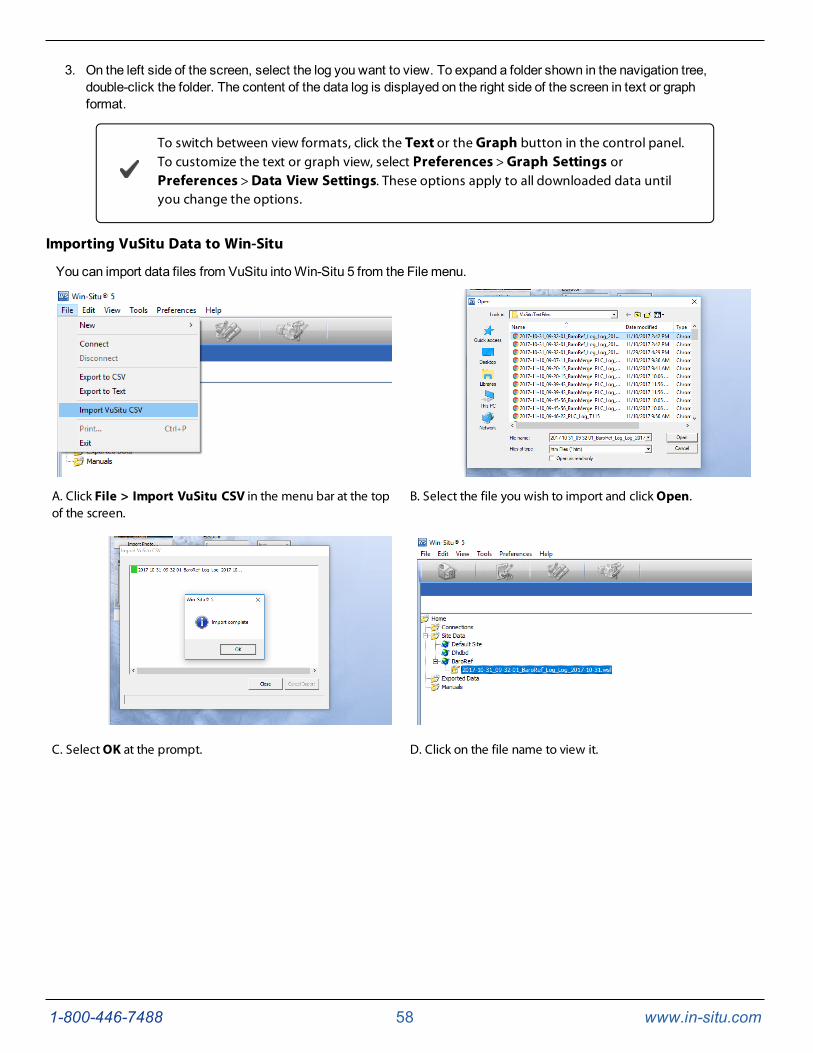
You can import data files from VuSitu intoWin-Situ 5 from the File menu.
A. Click File > Import VuSitu CSV in the menu bar at the topof the screen.
B. Select the file you wish to import and click Open.
C. Select OK at the prompt. D. Click on the file name to view it.

1-800-446-7488 59 www.in-situ.com
Using BaroMerge Software
BaroMerge Software is used to post-correct absolute (non-vented) level sensor data to eliminate barometric pressure effectsfrom themeasurements. BaroMerge Software can be accessed through theWin-Situ 5 Software Toolsmenu. BaroMergeprovides three options to correct data.
l Fixed Correction—A single offset value is applied to all selected log data. Use this option if you know thebarometric pressure of the site during the log, and know that it did not change.
l Manual Entry—Specify two or more correction values to apply to the log data. Use this option if you wish tomanually enter a data set of barometric pressure values.
l BaroTROLL log file—Absolute level sensor data points are individually corrected to reflect barometric pressurechanges that were logged by a BaroTROLL instrument during the approximate time period.
BaroMerge Input—BaroTROLL File
Log files that contain absolute data can be barometrically compensated using values logged by the In-Situ Inc. BaroTROLLInstrument. Select this method when you have access to a BaroTROLL log file covering approximately the same time periodas the data file you intend to correct.
To use this correctionmethod, you need the name of the BaroTROLL log file and the name(s) of the absolute log file(s) youwant to correct.

1-800-446-7488 60 www.in-situ.com
1. From the Toolsmenu inWin-Situ 5 Software, selectWin-Situ BaroMerge.
2. Select the "Use a BaroTROLL file:" option.
3. Click the browse button to the right of the file field.
4. Select a BaroTROLL file and click the check mark.
5. Values from the BaroTROLL file will be displayed in the next window. You can edit these values if necessary.
6. Click the right arrow button.
7. Select the log file(s) you intend to correct and click the check mark.
8. Compensated data files can be viewed or exported from theData tab.
BaroMerge Output
Your original log file is not changed. A new, corrected log file with the same name and path is created. The original “.wsl”extension is replaced by “-BaroMerge.wsl”.
1-800-446-7488 61 www.in-situ.com
Disconnecting an Instrument from the Software
Click the plug icon in the lower-right corner of the screen to disconnect the instrument from the software.
Disconnect the instrument from the communication device. Attach a desiccant pack if you are using a vented cable.
Connect to a Data Logger or PLC Controller
The instrument can be connected to a data logger or controller via a stripped-and-tinned RuggedCable System forcommunication using one of the following protocols.
l Analog (4-20mA)
l SDI-12
l RS485Modbus
l RS232Modbus (with a customer-supplied converter)
Stripped-and-tinned RuggedCable System includes a female connector on one end that connects to the instrument. Theuphole end terminates in stripped-and-tinned wires for connection to a PLC controller or data logger.
A shorter length Stripped-and-tinned RuggedCable System with amale connector is available to convert a female to femaleRuggedCable System to a stripped-and-tinned configuration.

1-800-446-7488 62 www.in-situ.com
1 PLC or Data Logger2 Stripped-and-tinned RuggedCable System with female connector3 Short stripped-and-tinned RuggedCable System with male connector4 RuggedCable System with female to female twist-lock connector5 Instrument

1-800-446-7488 63 www.in-situ.com
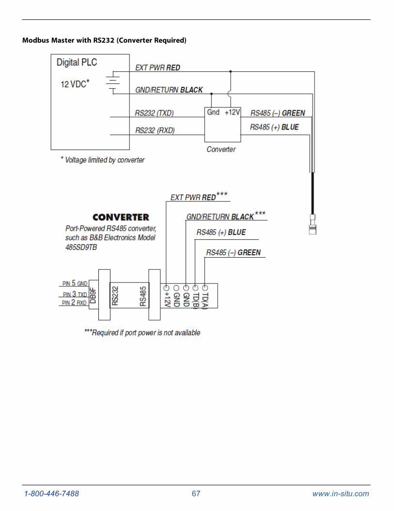
Wiring
Refer to the diagrams on the following pages for wiring information. Make sure that you trim and insulate unused wires. Theshield must be wired to a chassis ground or earth ground.
Signal Color Pin
Gnd/Return Black 6
Ext Power Red 5
4-20 mA Brown 4
RS485(-) Green 3
RS485(+) Blue 2
SDI-12 White 1

1-800-446-7488 64 www.in-situ.com
Analog (4-20 mA) 2 Wire

1-800-446-7488 65 www.in-situ.com
SDI-12 3 Wire

1-800-446-7488 66 www.in-situ.com
Modbus Master
1-800-446-7488 67 www.in-situ.com
Modbus Master with RS232 (Converter Required)

1-800-446-7488 68 www.in-situ.com
Power Connections
The Redwire provides power for Modbus and SDI-12modes. The Brownwire provides power for the 4-20mA mode. If poweris present on the Brownwire and not on the Red wire, the device enters the 4-20mA mode automatically and stays in the 4-20mode until power is removed from the Brownwire or is applied to the Red wire. The Redwire has priority. If power isapplied to the Red and Brownwires at the same time, the device will operate in Modbus or SDI-12modes but not in 4-20.
Communication Protocols
The device automatically switches betweenModbus and SDI-12modes depending on which of the two interfaces hasactivity. Modbus and SDI-12 cannot be used at the same time. The communication protocol that is currently in use will blockcommunication on the other.
Win-Situ 5 Software provides options for configuring analog/SDI-12 communications andModbus communications on theTools tab.
For additional information on Modbus and SDI-12 communications, including the SDI-12commands and Modbus registers, see www.in-situ.com/Technical_notes and scroll to theCommunications and Software Technical Notes section.
Redundant Logging
The instrument is capable of internal logging while participating in aModbus, SDI-12 or analog network. However, Win-Situ 5Software cannot communicate with the instrument while it is transmittingModbus, SDI-12, or 4-20mA analog data, and theinstrument cannot receive or respond toModbus, SDI-12, or 4-20mA analog commands while connected to a PC serial port.
If the PLC or data logger loses data, the data that was logged internally on the instrument can be retrieved usingWin-Situ 5Software.
If the PLC or data logger experiences power loss, the instrument will continue to collect data using its internal batteries andclock.

1-800-446-7488 69 www.in-situ.com
A port-powered RS485 converter like that shown for Modbus connections may be used for temporary connection of the LevelTROLL to a serial port on a PC.

1-800-446-7488 70 www.in-situ.com
Cleaning and Maintenance
Overview
It is important for users to perform scheduledmaintenance on their instruments to sustain the accuracy and longevity of theprobes and cables. The frequency of this maintenance depends on the characteristics of the deployment site, includinghumidity levels and the degree of fouling.
Users should be aware of the conditions at their deployment sites and develop appropriate maintenance schedules to replacedesiccant, clean the instruments, and send in the instruments for factory calibration. Users should check instruments oftenduring the first portion of the deployment to determine the frequency of maintenance. General maintenance should beperformed as often as possible. Factory maintenance and calibration should be performed every 12 to 18months.
Operating Considerations
The instrument has been designed to withstand harsh field conditions. However, as with any electronic instrument, it can bepermanently damaged if used outside its operating specifications.
Temperature
Review the instrument specifications to determine the operating range. Do not deploy instruments in such a way that icemayform on or near the sensors or cable connections. Ice formation is a powerful expansive force that can over-pressurize thesensor or otherwise cause damage that is not covered by the warranty.
Pressure Range
The instrument can withstand pressures of up to two times (2X) the rated range of the pressure sensor without damage,although it may not read correctly at such pressure. If the pressure range is exceeded by 3X, the sensor will be destroyed.
Batteries
Internal batteries in the instrument are not user-replaceable. The approximate percentage remaining is displayed inWin-Situsoftware or the Vu-Situ mobile app when the instrument is connected.
If batteries are completely exhausted, external power and battery pack options are available. See page 24.

1-800-446-7488 71 www.in-situ.com
Desiccant Pack Options
Small Desiccant
The Small Desiccant is a disposable cap that ships with In-Situ products. The small desiccant is meant to protect theinstrument and cable only during shipping and should not be used for deployments.
Large and Extra Large Desiccant
The Large and Extra-Large Desiccant are used to protect equipment deployed in the field. The Large Desiccant is best suitedfor low-humidity environments or deployments wheremaintenance occurs regularly. The Extra-Large Desiccant is designedfor high-humidity environments or deployments wheremaintenance occurs infrequently. Extra-Large Desiccants provide sixtimes the drying capability of the Large Desiccant. When the desiccant expires, both can be refilled with fresh desiccant andre-used (see Desiccant Refill Kit below). The Large Desiccant is available with an ABS or a titanium twist-lock connector,while the Extra Large Desiccant uses a titanium connector only.
Description Part Number
Large Desiccant, TitaniumLarge Desiccant, ABSExtra Large Desiccant
005181000535500090420
Outboard Desiccant
TheOutboard Desiccant is a replaceable desiccant pack designed to attach to the vent tube of a stripped-and-tinned cable.
Description Part Number
Outboard Desiccant 0051380

1-800-446-7488 72 www.in-situ.com
Desiccant Refill Kit
The Desiccant Refill Kit supplies desiccant for the Large Desiccant, Extra Large Desiccant, and the Outboard Desiccant. Italso contains replacement glass wool.
Description Part Number
Desiccant Refill Kit 0029140
Installing Desiccant with Twist-Lock Connectors
1. Remove the protective dust cap from the bottom of the desiccant pack, if applicable.
2. Remove expiring desiccant (if present) from the cable by grasping the textured section of the cable connector inone hand and the desiccant in the other. Twist in opposite directions to unlock the desiccant from the cable.
3. Attach the new desiccant pack to the twist-lock connector on the cable.
Installing Outboard Desiccant
Vented cablemust be installed with outboard desiccant to protect the cable and instrument electronics from condensation inhigh-humidity environments.
The desiccant can be removed from the vent tube, if necessary, to trim the conductor wires. However, youmust reinstall thedesiccant after trimming and connecting the wires.
1. Cut off the knot at the bottom of the vent tube extension.
2. Firmly attach the vent tube extension to the cable vent tube. Cover at least 6.4mm (0.25 in.) of the cable vent tubefor a secure attachment.
3. Use the attached hook-and-loop strap to secure the desiccant to the cable, below the stripped wires.

1-800-446-7488 73 www.in-situ.com
4. Remove the red dust cap from the black nylon cap to allow air to reach the cable’s vent tube.
1 Outboard desiccant is attached to thecable vent tube.
2 Desiccant is secured to the cable with astrap.
Using the Desiccant Refill Kit
1. Remove the black nylon vent cap from the top of the desiccant.
2. Pour out and discard the used desiccant. Check the glass wool in the bottom of the container and replace ifnecessary.
The glass wool prevents the desiccant beads from falling out the cable end of the desiccantpack. If the wool glass does this effectively, there is no need to replace it when refilling thedesiccant.
3. Fill the container with fresh desiccant. Replace the vent cap. Reattach to cable if removed.
Antifouling
TROLL Shield Nose Cone
The copper TROLL Shield Nose Cone is designed to reducemacro- andmicro-fouling of the pressure sensor on Level TROLLand Aqua TROLL Instruments. Reduced fouling on the sensor improves measurement accuracy and extends the length ofdeployments.
For optimum performance, the TROLL Shield Nose Cone should be replaced every 12months or sooner if site conditions areextremely harsh.
Description Part Number
TROLL Shield Nose Cone 0081480
1-800-446-7488 74 www.in-situ.com
O-ring Inspection and Replacement
ExamineO-rings for wear, dryness, discoloration, stretching, cracks, nicks, and brittleness. Replace O-rings when any ofthese conditions are present. Replacing O-rings on an annual basis, regardless of their condition, is the best way to protectagainst moisture damage.
Perform the following steps to replace anO-ring.
1. Remove and discard the damagedO-ring.
2. Use a clean, dry, soft cloth to clean the O-ring groove to remove dirt or residue.
3. Lubricate the new O-ring using high-vacuum grease.
a. Wash your hands thoroughly.
b. Apply a small amount of grease to the pad of your index finger, and rub your index finger and thumbtogether to spread the grease evenly.
c. Inspect the new O-ring and remove any debris stuck to it.
d. Rub your fingers around theO-ring until there is a thin layer of grease on the entire O-ring.
4. Install the O-ring in the groove and remove any excess lubricant with a clean cloth.
Do not allow water or lubricant to enter the connector.

1-800-446-7488 75 www.in-situ.com
Cleaning and Storage
Cleaning the Instrument
Clean the instrument body with water and a soft brush or plastic scouring pad, or soak overnight in amild acidic solution,such as household vinegar. NEVER submerge the connector portion of the instrument when it is not connected to a cable.
If the ports near the pressure sensor are clogged with silt or mud, try the following procedures.
l Agitate the instrument vigorously in a bucket of clean water.
l Apply a gentle rinse of water from awash bottle.
l In severe cases, remove the nose cone and clean out the holes with a soft brush or pipe cleaner.
Do not attempt to removematerial from the instrument by tapping the instrument against a surface. To avoid damage to thepressure sensor diaphragm, do not insert any object into the sensor opening or attempt to dig out dirt or other materials. Youvoid the instrument's warranty by inserting anything into the sensor opening. If contamination cannot be removedusing the recommendations above, please contact In-Situ for cleaning.
A TROLL pressure sensor with the nose cone removed. Do not insert ANY object into the sensor opening. Doing so voids thewarranty.
Twist-Lock Connectors
Keep the pins on all connectors free of dirt andmoisture by using the soft protective dust caps when cable is not attached.
Storage
Store the instrument in a clean, dry place. Place the protective red dust cap on the cable end or store with cable attached toprotect the connector pins andO-ring. For vented cables, ensure the desiccant used is the appropriate size and change itwhen needed. Store the instrument where it will not roll off a bench onto a hard surface or sustain other mechanical shock.Protect the instrument from temperature extremes using the following guidelines:
l Level TROLL Instruments—store within the temperature range -40° C to +80° C (-40° F to +176° F)
1-800-446-7488 76 www.in-situ.com
Factory Calibration and Service
In-House Factory Calibration
Factory calibration of In-Situ instruments should be performed every 12 to 18months, or at any point when the data appearsto drift significantly. Factory calibration includes a thorough cleaning, all operational checks, necessary firmware upgrades,O-ring replacement, and full range calibrations of the pressure sensor, temperature sensor, and conductivity sensor (whenapplicable).
Return Materials Authorization (RMA) Form
To obtain a factory calibration, fill out and return the online ReturnMaterials Authorization (RMA) form located at www.in-situ.com/.
Obtaining Repair Service
If you suspect your system is malfunctioning and repair is needed, you can help assure efficient servicing by following theseguidelines:
1. Call or email In-Situ Technical Support. Have the product model and serial number available.
2. Be prepared to describe the problem, including how the product was used and the conditions noted at the time ofthemalfunction.
3. If Technical Support determines that service is needed, they will ask your company to fill out the RMA form andpre-approve a specifiedmonetary amount for repair charges. When the form and pre-approval is received,Technical Support will assign an RMA (ReturnMaterial Authorization) number.
4. Clean the product as described in themanual.
5. If the product contains a removable battery, remove and retain it unless you are returning the system for a refund orTechnical Support states otherwise.
6. Carefully pack your product in its original shipping box, if possible.
7. Mark the RMA number clearly on the outside of the box.
8. Send the package, shipping prepaid, to:
In-SituATTN: Repairs221 East Lincoln AvenueFort Collins, CO 80524
The warranty does not cover damage during transit. In-Situ recommends insurance for all shipments. Warranty repairs will beshipped back prepaid.
Outside the U.S.
Contact your international In-Situ distributor for repair and service information.
1-800-446-7488 77 www.in-situ.com
Guidelines for Cleaning Returned Equipment
Please help us protect the health and safety of our employees by cleaning and decontaminating equipment that has beensubjected to potential biological or health hazards, and labeling such equipment. Unfortunately, we cannot service yourequipment without such notification. Please complete and sign the form on page 78 (or a similar statement certifying that theequipment has been cleaned and decontaminated) and send it to us with each instrument.
l We recommend the glassware cleaning product, Alconox, available from In-Situ and from laboratory supplycompanies.
l Clean all cables and remove all foreignmatter.
l Clean the cable connectors with a clean, dry cloth. Do not submerge the connectors.
l Clean the instrument including the nosecone, cable head, and protective caps.
If an instrument is returned to our Service Center for repair or recalibration without astatement that it has been cleaned and decontaminated, or if it is the opinion of ourService Representatives that the equipment presents a potential health or biologicalhazard, we reserve the right to withhold service until proper certification is obtained.

1-800-446-7488 78 www.in-situ.com
Decontamination and Cleaning Form

1-800-446-7488 79 www.in-situ.com
Troubleshooting
In addition to the following troubleshooting items, the In-Situ website includes instructional videos, technical notes, andmore. Seewww.in-situ.com/.
Problem Possible Cause Possible Solution
Win-Situ 5 Software cannotconnect to the instrument.
Wrong COM port is selected,communication settings are incompatible,cable connections are loose or dirty, orbatteries are low.
Make sure cable connections are tight andconnectors are clean and dry.
Make sure the cable is securely attached to theinstrument.
Make sure the correct COM port is selected (selectPreferences > Comm Settings to verify).
Make sure the communication settings in Win-Situand in the instrument match. To reset the devicecommunication settings to the serial defaults, click“Reset all Devices” in the Comm Settings dialog(Preferences > Comm Settings).
Make sure the internal battery has voltageremaining, or external power is supplied.
See www.in-situ.com/Technical_notes and scrollto the Communications and Software TechnicalNotes section for more information.
Real-time readings display thewrong units. Default units are being used.
Click the Sensors tab, select the sensor, click theconfigure button and select the desired units foreach parameter in the Sensor Setup window.
Cannot add a new log.
Only one active log can reside in thedevice at a time—an active log is a logthat is Ready, Pending, Running, orSuspended as shown in the Statuscolumn of the Logging Tab.
The device has its maximum number oflogs already stored—the Level TROLL300, 500, and Baro TROLL have acapacity of 2 logs.
Stop or delete the log if possible. Alternatively,configure the new log after the active log iscompleted.
Download, and then delete a log you no longerneed. This will make room for an additional log onthe device.
New log exceeds availablememory (software message).
The log as configured would exceed thedevice memory.
Edit the log and select a longer sampling interval.
If available, select the "wrap data" option. Thiscauses more recent data to overwrite older datawhen memory is full.
For a log with a scheduled start, select None as thestop condition, or select a stop time that is closer tothe start time.

1-800-446-7488 80 www.in-situ.com
Problem Possible Cause Possible Solution
Cannot configure level or otherparameters using the Configurebutton on the Sensors tab. TheSensor Setup screen is shown, butthe Configure... button is dim.
The instrument is actively polling(continually updating real-time readings)in the Home tab.
The instrument has an active log—a logthat is Ready, Pending, Running, orSuspended as shown in the Statuscolumn of the Logging tab. Only oneactive log can reside in the device at atime.
Return to the Home tab and stop real-timereadings by clicking the Play button.
Stop or delete the log if possible. Alternatively,configure parameters after the log is complete.

1-800-446-7488 81 www.in-situ.com
Declarations of Conformity and Similarity
Level TROLL 400 Instrument
1-800-446-7488 82 www.in-situ.com
Level TROLL 500 Instrument

1-800-446-7488 83 www.in-situ.com
Level TROLL 700 Instrument
1-800-446-7488 84 www.in-situ.com
TROLL Com Communication Device

1-800-446-7488 85 www.in-situ.com
BaroTROLL Instrument


![Operator'sManual...Operator'sManual ® 2780 PSi MAX 2.5 GPff] MAX _odei No. 580.752100 wAReeeG Before usingthis product, readthis manualand follow atI SafetyRutes and Operating Instructions](https://img.dokumen.tips/doc/110x75/5ea8c7e7876aec753b5f1889/operatorsmanual-operatorsmanual-2780-psi-max-25-gpff-max-odei-no-580752100.jpg)