Embed Size (px)
Citation preview

NOTICE The enclosed materials are considered proprietary property of ZENON Environmental Inc. No assignments, either implied or expressed, of intellectual property rights, data, know how, trade secrets or licenses of use thereof are given. All information is provided exclusively to the addressee for the purposes of evaluation and is not to be reproduced or divulged to other parties, nor used for manufacture or other means or authorizes any of the above, without the express written consent of ZENON Environmental Inc. The acceptance of this document will be construed as an acceptance of the foregoing conditions.
OPERATOR’S MANUAL
For
ZENOPURE LABORATORY WATER SYSTEMS
ULTRA SERIES
Revision: 5
ZENON Environmental Inc. 3239 Dundas Street West
Oakville, Ontario L6M 4B2
Phone: (905) 465-3030 Fax: (905) 465-3050
NOVEMBER 2003 Version: 112003

CAUTION
READ THE FOLLOWING PRECAUTIONS!
1. This manual must be read and understood in its entirety before operating the
system.
2. If operating specifications within this manual are not strictly followed, the warranty will be null and void.
3. All drain line sizes are to be installed as per drawings.
4. Any maintenance conducted on this system other than replacement of consumable items; by any person(s) than a ZENON trained technician will nullify all warranties.

Operator Manual ZENOPURE Laboratory Water Purification Systems ULTRA Series
TABLE OF CONTENTS
1 INTRODUCTION........................................................................................................3
2 SYSTEM OVERVIEW................................................................................................4
3 UNPACKING / INSTALLATION ..............................................................................5
3.1 UNPACKING ..........................................................................................................5 3.2 INSTALLATION.......................................................................................................6
3.2.1 Free Standing ...............................................................................................6 3.2.2 Wall Mounting .............................................................................................6 3.2.3 Fluid Connections ........................................................................................6 3.2.4 Pretreatment Cartridge .................................................................................7 3.2.5 Mixed Bed DI Cartridges .............................................................................8 3.2.6 Electrical Connection...................................................................................8
4 SYSTEM OPERATION ..............................................................................................9
4.1 INITIAL SYSTEM STARTUP .....................................................................................9 4.2 ROUTINE SYSTEM SHUTDOWN ............................................................................10 4.3 CLEANING AND SANITIZATION ............................................................................11
4.3.1 General Information ...................................................................................11 4.3.2 RO Cleaning/Sanitizing Procedure ............................................................11 4.3.3 Sanitizing RO Reservoir and Recirculation System Components .............13
5 MAINTENANCE ......................................................................................................14
5.1 ROUTINE MAINTENANCE.....................................................................................14 5.1.1 Prefilter Replacement.................................................................................14 5.1.2 Activated Carbon Impregnated Prefilter ....................................................15 5.1.3 Mixed Bed Deionization Cartridge ............................................................15 5.1.4 0.2µ Final Filter .........................................................................................16
5.2 PERIODIC MAINTENACE ......................................................................................17 5.2.1 RO Membrane............................................................................................17 5.2.2 ULTRAfiltration Membrane ......................................................................17 5.2.3 0.2µ Reservoir Vent Filter .........................................................................17
6 CONTROLLER DETAILS........................................................................................18
6.1 LAYOUT AND FUNCTION OF THE CONTROLS ........................................................18 6.2 CONTROLLER DESCRIPTION ................................................................................18 6.3 CONTROLLER SPECIFICATIONS ............................................................................18 6.4 CONTROLLER KEY FUNCTIONS ...........................................................................19

Operator Manual ZENOPURE Laboratory Water Purification Systems ULTRA Series
7 SYSTEM OPERATION ............................................................................................20
7.1 GENERAL OPERATION .........................................................................................20 7.2 DISPLAY..............................................................................................................20 7.3 OPERATING STATUS MESSAGES ..........................................................................21 7.4 OPERATING HOURS .............................................................................................22 7.5 TEMPERATURE ....................................................................................................22 7.6 WARNING MESSAGES .........................................................................................23 7.7 RESERVOIR CONDUCTIVITY INDICATOR ..............................................................25
8 GLOSSARY...............................................................................................................26
8.1 REVERSE OSMOSIS SPECIFIC TERMS: ..................................................................26
9 TEMPERATURE EFFECTS.....................................................................................27
10 ORDERING SPARES AND CONSUMABLES...................................................28
11 FACTORY SETPOINTS.......................................................................................29
12 THEORY OF OPERATION..................................................................................30
12.1 FILTRATION SPECTRUM .......................................................................................30 12.2 REVERSE OSMOSIS: AN INTRODUCTION ..............................................................31

Operator Manual ZENOPURE Laboratory Water Purification Systems ULTRA Series
ZENON Environmental Inc. Rev: 5 November 2003 - 3 -
1 INTRODUCTION This manual describes the ZENOPURE ULTRA Series – Laboratory Water Purification System and provides details of correct installation and operation that must be followed in order to ensure optimal system performance. All personnel working with the system should read the manual completely, and be familiar with how the entire system is designed to operate. Operation of the system outside the limits described in this manual may impair system performance and invalidate portions of the warranty or the entire warranty.
By following the procedures in this manual the operators will be able to successfully install, start-up and operate the ULTRA water treatment system. ZENON Environmental Inc. can also advise on further training or training courses on request.
If there are any questions about this manual or the operation of the system, please contact or service department,
ZENON Environmental Inc.
Service Department
3239 Dundas Street West
Oakville, Ontario, L6M 4B2
Telephone: (905) 465-3030
Fax: (905) 465-3050
http://www.zenon.com

Operator Manual ZENOPURE Laboratory Water Purification Systems ULTRA Series
ZENON Environmental Inc. Rev: 5 November 2003 - 4 -
2 SYSTEM OVERVIEW The ULTRA Series of laboratory water purification systems is available in three models; the ULTRA 35 (35 lph), ULTRA 70 (70 lph) and the ULTRA 150 (150 lph). The ULTRA system includes the following components:
• Pretreatment cartridge • 200 PSI RO pump • Reverse Osmosis membrane(s)
1 membrane (2.5” x 21”) in the ULTRA 35, 2 membranes (2.5 “ x 21”) in the ULTRA 70, 2 membranes (4” x 21”) in the ULTRA 150).
• 2 Deionization (DI) cartridge columns • ULTRAfiltration membrane • 0.2µ final filter • Solid state control system and a variety of instrumentation including resistivity
meter and pressure gauges • 35 litre reservoir with conductivity monitor light and level controls • Recirculation pump
All systems are designed to produce ASTM Type 1 Reagent Grade Water (for application requiring ULTRApure water) and Type 4 Reagent Grade Water (for general laboratory use). A schematic flow diagram for the ULTRA Series is presented herein.

Operator Manual ZENOPURE Laboratory Water Purification Systems ULTRA Series
ZENON Environmental Inc. Rev: 5 November 2003 - 5 -
3 UNPACKING / INSTALLATION
3.1 Unpacking The system has been shipped completely assembled except for the installation of the prefilter cartridge and the DI cartridges. These cartridges are packed separately within the crate. Remove the cartridges and the unit from the crate and inspect carefully for signs of physical damage that may have occurred during shipping. If any damage is found, save all packing material and notify supplier and carrier responsible for shipping. Confirm that all parts are received before proceeding. Your system is complete with the following items for installation and system operation.
Table 1. Shipping / Installation Parts List Item Part # Quantity Description 1 1010056 1 10” x 5 µ Carbon impregnated
prefilter 2 1010006 1 10” x 5 µ Prefilter 3 1010058 2 20” long Deionization cartridge 4 1008458 1 Straight connector ½”
compression x ½” MNPT 5 1008456 1 Straight connector 3/8”
compression x 3/8” MNPT 6 1010857 8’ Polyethylene Tubing – ½” OD 7 1008398 8’ Polyethylene Tubing – ½” OD 8 1009706 2 Set of “J” Clips 9 1010194 1 Cartridge filter bowl wrench 10 1 Operations Manual 11 1001063 2 Clear Filter Housing 12 1001064 1 White Filter Housing
Please take a moment now and confirm that you received all parts as indicated on this list. Contact ZENON immediately if you are missing parts.

Operator Manual ZENOPURE Laboratory Water Purification Systems ULTRA Series
ZENON Environmental Inc. Rev: 5 November 2003 - 6 -
3.2 Installation The ULTRA series systems can be installed on a supported wall or allowed stand atop of a bench. Depending upon your preference, both are reviewed herein and required parts are automatically included. Please note that maintenance is more difficult to complete on systems that are installed on a wall. Please contact ZENON if you wish to review these two options. 3.2.1 Free Standing The ULTRA unit is supplied with 6 plastic non-marking feet for mounting on a bench top. A bench height of 33” to 36” is a comfortable working height for operators. Please note that the operating weight of the system is approximately 180 lbs (82 kgs approx.) and you should ensure that the bench can withstand this weight. 3.2.2 Wall Mounting The unit is best mounted on concrete or wooden walls. Plaster (drywall) is not suitable unless a wooden faceplate is first securely attached spanning at least two studs. This unit uses four (4) J-clip, two (2) longer and two (2) shorter, in order to wall mount the unit. Four long bolts have been provided to mount the longer J-clips to the unit. Specific mounting instructions are outlined within this Manual. Depending on wall construction, anchors (not included) may be required to mount the shorter J-clips to the wall. 3.2.3 Fluid Connections The ULTRA 35, ULTRA 70 and ULTRA 150 models have been shipped with the attached hoses heat sealed to prevent leakage. Remove septums or cut off the seals once the unit is in position. Any flow from the hoses should be allowed to drain. 3.2.3.1 Feedwater Connection
Connect the 2.5 m (8’) length of 12 mm (1/2”) Ø plastic tubing attached to the inlet of the pretreatment vessel to the feed water supply. NOTE: It is recommended that a shutoff valve should be installed on the feed water line as close to the unit as possible. NOTE: It is recommended that a shutoff valve be
Operator Manual ZENOPURE Laboratory Water Purification Systems ULTRA Series
ZENON Environmental Inc. Rev: 5 November 2003 - 7 -
installed on the feedwater supply at the closest point of exit from the facility plumbing line or wall.
3.2.3.2 Concentrate to Drain Connection Connect the second length of 10 mm (3/8”) Ø tubing from the solenoid at the outlet of the RO membrane to the closest drain. NOTE: The drain line must be sized to accommodate the concentrate flow from the ULTRA system. Flooding on the floor may occur if the drain line is not of an appropriate size. Contact ZENON if you are unsure.
3.2.3.3 RO Water Discharge The ULTRA Series model has a hand valve (spigot) for RO permeate water and is located on the lower right front of the unit. NOTE: Ensure that this valve is closed at all times when not in use.
3.2.3.4 Ultrapure Water Discharge The second hand valve (spigot), located on the clear acrylic door is the discharge point for Type I Ultrapure water. NOTE: Ensure that this valve is closed when not in use.
3.2.4 Pretreatment Cartridge An activated carbon impregnated prefilter cartridge or 5 micron prefilter (depending on your application and other pretreatment that may exist or has been supplied by ZENON) has been supplied with the system. To install the cartridge, unscrew housing in a clockwise direction using the housing wrench provided with the system. Check and confirm that the O-ring in the top of the bowl is in the correct position and seats properly in the groove. Insert the prefilter cartridge in the housing and ensure that the bottom sits properly over the raised ring on the bottom of the housing. Replace housing by aligning the threads of the housing over the threads of the housing head that is mounted on the system and turning it in a counter-clockwise direction. Ensure there is a tight fit. NOTE: Do not over tighten using the wrench, the fit should be snug (hand tight) and will not require a great deal of strength. Alternative pretreatment methods can also be used depending on the particular feed water quality. If the feed water to the unit has a residual free chlorine level less than 0.1 mg/L, a 5 micron prefilter cartridge can be installed in the housing provided upstream of the RO pump. In the event the feed water contains free chlorine, removal of the chlorine to a

Operator Manual ZENOPURE Laboratory Water Purification Systems ULTRA Series
ZENON Environmental Inc. Rev: 5 November 2003 - 8 -
level less than 0.1 mg/L is required to insure optimum membrane life. This is achieved either:
a) With the installation of the carbon impregnated prefilter cartridge in the housing provided. Contact ZENON if you are not sure which cartridge type you have.
b) With the installation of a granular activated carbon cartridge in a separate housing
upstream of the unit (ordered separately) and a 5-micron prefilter cartridge in the housing provided.
3.2.5 Mixed Bed DI Cartridges Remove the two Deionization (DI) cartridges from the packing material. To install the cartridges one at a time, unscrew a 20” housing in a clockwise direction using the housing wrench provided with the system. Check and confirm that the O-ring in the top of the bowl is in the correct position and seats properly in the groove. Insert one DI cartridge in the housing and ensure that the bottom sits properly over the raised ring on the bottom of the housing. Replace housing by aligning the threads of the housing over the threads of the housing head that is mounted on the system and turning it in a counter-clockwise direction. Ensure there is a tight fit by using the housing wrench supplied. Repeat these few steps for the second of the two DI cartridges. NOTE: Do not over tighten using the wrench, the fit should be snug and will not require a great deal of strength. 3.2.6 Electrical Connection The unit requires one (1) grounded 115 VAC receptacle located within 1.2m (4’) of the system. The unit has its own 15 A fuse (located on main control circuit board) to protect the system in the event of a short circuit. Make sure the power switch on the system is in the OFF position before plugging the unit into the electrical socket on the wall. NOTE: Please ensure that the electrical wire is not impeding traffic flow and is not sitting in water. Electricity can be very dangerous and care is always required. Please contact ZENON immediately if you are unsure or have any questions prior to completing this step.

Operator Manual ZENOPURE Laboratory Water Purification Systems ULTRA Series
ZENON Environmental Inc. Rev: 5 November 2003 - 9 -
4 SYSTEM OPERATION
4.1 Initial System Startup
a) Ensure that prefilter cartridge has been installed as per 3.2.4 above. b) Ensure that DI cartridges have been installed as per 3.2.5 above.
c) Check that all water and electrical connections have been completed properly and
in accordance with the previous section.
d) Place the RO product water permeate tube to drain. Membranes are shipped in a preservative and this will be flushed from the system during the initial start-up. This tube will be connected to the RO water product tank later (see item j below).
e) Turn on the water supply. Check to make certain there are no leaks in the water
supply piping. If leaks appear, tighten fittings. If leak persist, contact ZENON. All systems are tested prior to shipment. Fittings can become loose during shipping.
f) With the water supply turn on, the prefilter pressure gauge should register pressure
immediately. Check that the feed pressure is greater than 30 psig. If the feed supply pressure does not meet the minimum of 30 psig, contact ZENON for assistance.
g) To avoid airlock, with the feed supply water turned on, vent any air from the
pretreatment cartridge by pressing down on the red button until all the trapped air escapes. NOTE: Once the air has been purged, only water will vent through the red button. This is natural, and any water that spills on to the base of the cabinet should be wiped up.
h) Proceed to check system for leaks. If leaks occur, tighten the tube fittings as
needed. If leaks persist then contact ZENON. i) Start RO by pressing the green button on the control panel. After the
pump has run for about 30 seconds, the RO pressure gauge should stabilize within the range between 175 to 225 psig. Let the RO run for 1 hour to insure that the
POWER
Operator Manual ZENOPURE Laboratory Water Purification Systems ULTRA Series
ZENON Environmental Inc. Rev: 5 November 2003 - 10 -
sanitizing and preserving agents in which the membranes are stored have been properly flushed out. Ensure that the RO water is discharged to drain through the permeate tube and waste all the initial water generated from the system to drain.
j) Place the system into STANDBY by pressing the green button. Connect
RO product water outlet to tank inlet. Press the green button initiating OPERATING Mode. While the RO water storage reservoir is filling the Recirculation Pump will automatically start 2 minutes after activating the low level switch. When the storage reservoir is approximately half full, begin venting the DI cartridges one at a time to remove trapped air by pressing down on the red button located at the top of each DI bowl (the same procedure as listed above in item g). Once all the air has been vented, the outlet pressure gauge on the downstream side after the second DI cartridge should read between 30 and 50 psig. As water continues to recirculate through the DI cartridge columns, the Ultrapure product water quality will steadily increase as observed on the resistivity monitor.
k) Manually flush the UF membrane for 2 minutes using the manual flush valve
located on the housing of the UF membrane element. Waste the UF concentrate to drain. Closed hand valve after rinse operation is complete.
l) Vent air from the 0.2-micron final filter by unscrewing the white vent cap until all
the air has escaped.
4.2 Routine System Shutdown
a) Close DI product water discharge hand valve (spigot). b) Press green button on the control panel, placing the system into
STANDBY Mode. c) Close feed water supply valve (customer supplied).
NOTE Plastic fittings will “creep” with time and some tightening and/or retaping with teflon
tape may be required to stop small leaks.
POWER
POWER
POWER

Operator Manual ZENOPURE Laboratory Water Purification Systems ULTRA Series
ZENON Environmental Inc. Rev: 5 November 2003 - 11 -
4.3 Cleaning and Sanitization 4.3.1 General Information It is generally recommended that the RO section of the unit be cleaned and sanitized on a routine basis to insure maximum product water quality over the long term and optimize system operating life. The frequency of cleaning will depend on the specific operating conditions (operating time, feed water quality, routine system maintenance, attention to consumable part replacements). Under normal conditions, it is recommended that the system be cleaned and sanitized on a monthly to quarterly basis. The chemicals required are available from ZENON and listed below: Table 2. Membrane Cleaning and Sanitizing Chemicals 4.3.2 RO Cleaning/Sanitizing Procedure The same procedure will be used for cleaning and sanitizing the RO membranes.
a) Place the system into STANDY mode. If the system is in OPERATING mode, pressing the green button once will toggle the system into STANDBY mode.
b) Close the customer feed water supply valve located upstream of the system.
Cleaner Part # Description Application MC-1 8010092 Acid Cleaner to
remove Inorganic / Scale fouling from the membrane
5 grams to a pH of 2.5-3.5 1 teaspoon
MC-4 8010741 Caustic Cleaner to remove Organic fouling from the membrane
4 grams to a pH of 10.5-11.0 1 teaspoon
MP-4 8010109 Sanitizing chemical to sanitize all components
5 grams to a pH of 3.5-4.0 1 teaspoon
POWER

Operator Manual ZENOPURE Laboratory Water Purification Systems ULTRA Series
ZENON Environmental Inc. Rev: 5 November 2003 - 12 -
c) Relieve the feed water pressure within the10 inch prefilter housing by pressing the
RED button (bleed valve) slowly. This button is located at the top of the prefilter housing. The prefilter pressure should have been reduced to 0 psig. If not, check that the customer feed valve (step b above) has been fully closed. NOTE: this operation will cause a release of a small amount of water to come out of the prefilter housing, and this may spill down on to the cabinet bottom. By releasing this pressure slowly, you can minimize spraying and spillage. Wipe excess water up with paper towels.
d) Disconnect RO permeate tubing from inlet to the RO reservoir tank and direct this
length of flexible tubing from the RO permeate discharge down to the drain.
e) Using the housing wrench provided, remove the 10-inch prefilter cartridge housing and remove the prefilter cartridge, leaving the water remaining in the bowl. NOTE: discard prefilter. Placing the prefilter back into the system after the cleaning or sanitizing step may re-introduce harmful contaminants.
f) With care and proper safety protection (e.g. safety glasses, rubber gloves, etc)
measure out the appropriate amount of cleaning chemical from the above Table 2 and carefully add it to the water in the prefilter bowl.
g) Using a mixing rod, (not provided), thoroughly mix the solution until it is
completely dissolved.
h) Re-install the prefilter housing turning it counter-clockwise, again using the housing wrench provided to tighten. Ensure the O-ring is seated properly.
i) Press the green button and place the system into OPERATING mode
allowing the RO pump to run for 6-8 seconds, then press the green button and return the system to STANDBY Mode.
j) Let the system sit idle for 20-30 minutes, allowing the membranes to soak in the
solution.
k) Press the green button to place the system in OPERATING mode and flush system to drain (permeate and concentrate) for 30 minutes to remove all the cleaning solution residuals.
POWER
POWER
POWER

Operator Manual ZENOPURE Laboratory Water Purification Systems ULTRA Series
ZENON Environmental Inc. Rev: 5 November 2003 - 13 -
l) Remove discharge tubing added for draining solution. Reconnect permeate tubing to the inlet of the RO storage reservoir. The system is now ready for production.
4.3.3 Sanitizing RO Reservoir and Recirculation System Components
a) Fill the RO reservoir with RO permeate while in OPERATING mode. Place system into STANDBY mode. Add 3.5 ml of 5% chlorine bleach and mix thoroughly. This will create a 5 mg/L chlorine sanitizing solution.
b) Remove DI cartridges from the DI cartridge housings, and re-install the empty DI
cartridge housings on the unit. NOTE: The best time to sanitize is before a new set of DI cartridges are installed. This will ensure a successful sanitization by not returning a potentially contaminated DI cartridge into operation following a sanitization.
c) Place the system back into OPERATING mode and recirculate the sanitizing
solution through the DI bowls, ULTRAfiltration membrane and Final Bacteria filter for approximately 30 minutes. Prior to completing this step, open the Ultrapure water hand valve (spigot located on the acrylic door) for 2 0 –to 30 seconds to pass a small amount of the solution sanitizing through the outlet door tap. Repeat this step with the ULTRAfilter concentrate flush tap to sanitize as well.
d) Thoroughly rinse out the recirculation loop with RO water (at least twice). This
will involve opening the ULTRApure hand valve (spigot) and ULTRAfilter flush tap periodically allowing the RO reservoir to rinse down and re-fill. This procedure may take up to two hours to eliminate the presence of any residual chlorine.
e) Once all residual chlorine has been purged from the system, place the system in
STANDBY mode and install (2) new DI cartridges. The system is now ready to be switched to OPERATING mode.
Operator Manual ZENOPURE Laboratory Water Purification Systems ULTRA Series
ZENON Environmental Inc. Rev: 5 November 2003 - 14 -
5 MAINTENANCE Due to the nature of the different components within this system and the system operation, there are different levels of maintenance required to maintain optimal performance and quality from the ULTRA series of systems. Routine maintenance includes the replacement of consumable items on a regular basis to maintain water quality and system performance. Periodic maintenance includes operations that are only required infrequently but are no less important to maintaining optimal performance from the system over the long term.
5.1 Routine Maintenance The frequency of replacing consumable items within the ULTRA series of systems will vary directly with the feedwater quality delivered to the system, the hours of operation of the system, and the day-to-day care the system receives by the operators. 5.1.1 Prefilter Replacement The 10” 5-micron prefilter or carbon impregnated 5-micron filter (depending on the system and option selected for your application) will require regular replacement. Its purpose is to remove suspended solids from plugging the downstream RO membranes. If this filter is not replaced on a regular basis, plugging of the RO membrane is a far more costly item to replace and will have a significant impact on system performance. The prefilter is a depth filter. It will trap suspended particles found within the feedwater. As this dead-end filter becomes plug, it becomes more difficult to pass water through it. As a result, the required pressure to filter water becomes higher. It is this phenomenon of fouling that will eventually cause the filter to require replacement. To monitor the performance of the filter, a pressure gauge is included upstream of the prefilter and immediately downstream of the prefilter. When the system is first turned on, you will note what the feed supply pressure is and you will notice that both the feedwater prefilter pressure gauge and downstream prefilter pressure gauge will have almost identical readings. As the prefilter becomes plugged, the pressure drop across the prefilter will increase. This will cause these two gauges to show different readings. When the downstream pressure gauge is showing 10 psig less than the feedwater supply pressure gauge, it is time to replace the prefilter with a new one.

Operator Manual ZENOPURE Laboratory Water Purification Systems ULTRA Series
ZENON Environmental Inc. Rev: 5 November 2003 - 15 -
To replace the prefilter, close the customer feed valve, which should be located upstream of the system. Once the valve has been closed, relieve the pressure within the prefilter cartridge housing slowly by slowly depressing the red vent button located on top of the prefilter housing. Unscrew the cartridge prefilter housing in a clockwise manner using the housing wrench provided, until the bowl has been removed. Remove the old filter and replace with a new filter of similar filtration capabilities, ensuring that the filter is centered on the ring at the base of the housing. Screw on prefilter housing in a counter-clockwise manner ensuring that the prefilter housing O-ring is in place (hand tight). Open customer feed valve and vent air from prefilter bowl by depressing the red button located on the top of the prefilter housing. Check for leaks prior to placing system into operation. 5.1.2 Activated Carbon Impregnated Prefilter Replacement frequency of this cartridge is dependent upon the level of particulates/colloids, chlorine concentration and on the concentration of organics in the feed water. As suggested within 5.1.1, the pressure drop across this filter will increase as this filter becomes plugged. As with the 5-micron prefilter, when the pressure gauges show a 10 psig or greater difference between the two located on the prefilter column, it is time to replace the filter. In general, replacement on a monthly basis is typical. To replace the prefilter, close the customer feed valve, which should be located upstream of the system. Once the valve has been closed, relieve the pressure within the prefilter cartridge housing slowly by slowly depressing the red vent button (bleed valve) located on top of the prefilter housing. Unscrew the cartridge prefilter housing in a clockwise manner using the housing wrench provided, until the bowl has been removed. Remove the old filter and replace with a new filter of similar filtration capabilities, ensuring that the filter is centered on the ring at the base of the housing. Screw on prefilter housing in a counter-clockwise manner ensuring that the prefilter housing O-ring is in place (hand tight). Open customer feed valve and vent air from prefilter bowl by depressing the red button (bleed valve) located on the top of the prefilter housing. Check for leaks prior to placing system into operation. 5.1.3 Mixed Bed Deionization Cartridge The DI cartridges should be replaced whenever the product water quality as registered on the Resistivity meter cannot be maintained at or above the minimum acceptable level as determined by the user. NOTE: Prior to making the decision to replace the DI cartridges,

Operator Manual ZENOPURE Laboratory Water Purification Systems ULTRA Series
ZENON Environmental Inc. Rev: 5 November 2003 - 16 -
flush the ULTRAfilter and leave the system on internal recirculation for at least 5 minutes to 10 minutes. At the end of the flush and recirculation steps, place the system in normal production mode and if the water quality on the Resistivity meter does not improve, then it is time to replace the DI cartridges. NOTE: You must replace both DI cartridge columns at the same time, and never replace just one DI cartridge. No estimate of the frequency of replacement is recommended because specific installations have their own minimum quality standards. NOTE: If your requirements do not allow adequate time for this procedure, replace the DI cartridges when the quality falls below the acceptable limit. To replace the DI cartridges, close the customer feed valve, which should be located upstream of the system. Once the valve has been closed, relieve the pressure within the DI cartridge housings slowly by slowly depressing the red vent button located on top of the DI cartridge housing. Unscrew the DI cartridge housing in a clockwise manner using the housing wrench provided, until the housing has been removed. Remove the old DI cartridge and replace with a new DI cartridge, ensuring that the DI cartridge is centered on the ring at the base of the housing. Screw on prefilter housing in a counter-clockwise manner ensuring that the DI cartridge housing O-ring is in place. Open customer feed valve and vent air from DI cartridge bowl by depressing the red button located on the top of the DI cartridge housing. Check for leaks prior to placing system into operation. 5.1.4 0.2µ Final Filter The projected life of the final filter is between six and twelve months. Factors strongly affecting the life of the filter include storage conditions of the RO water and the frequency of RO membrane cleaning/sanitization. The specific replacement will be determined by the user based on the end use of the water and any required product water specifications that have to be met. To replace the Final Filter, slide the old unit out from the polytubing and discard. Insert the ends of a new one directly in the polytubing as was installed for the old filter. Slowly fill the absolute filter and vent air by release of the small the small threaded cap on the top of the filter head.
Operator Manual ZENOPURE Laboratory Water Purification Systems ULTRA Series
ZENON Environmental Inc. Rev: 5 November 2003 - 17 -
5.2 Periodic Maintenance 5.2.1 RO Membrane The operating life of the RO membrane is strongly dependent upon the feed water quality and the frequency of cleaning and sanitization. Under typical conditions (feed water: 300 µS/cm, <0.1 mg/l chlorine; cleaning/sanitizing on a monthly basis), the RO membrane is expected to last between 2-3 years. Operators should not attempt to replace these membranes unless they have been formally trained by ZENON. ZENON Field Service Representatives should complete this maintenance. 5.2.2 ULTRAfiltration Membrane The UF membrane operating life is dependent on the frequency of manual flushing. NOTE: It is important that the ULTRAfilter membrane concentrate be flushed (using the manual flush tap) twice a day. If the foulant or contaminant material is allowed to build up without routine flushing, both the life of the membrane and the quality of the product water will be reduced. The UF membrane should be replaced a minimum of every 2-3 years to ensure good product water quality. Operators should not attempt to replace these membranes unless they have been formally trained by ZENON. ZENON Field Service Representatives should complete this maintenance. 5.2.3 0.2µ Reservoir Vent Filter The vent filter on the reservoir should be replaced whenever the 0.2µ final filter is replaced, every 6 to 12 months.
Operator Manual ZENOPURE Laboratory Water Purification Systems ULTRA Series
ZENON Environmental Inc. Rev: 5 November 2003 - 18 -
6 CONTROLLER DETAILS
6.1 Layout and Function of the Controls The controls and indicators used in the operation of the ZENOPURE system are outlined below. The operator must be thoroughly familiar with the controls and their respective functions to maintain the quality of the product water and to insure efficient system operation.
6.2 Controller Description The ZENON ULTRA series systems are controlled by a state of the art control system, which combines features that have not previously been available in one compact unit. The ULTRA series systems employ a microprocessor-controlled system that can monitor temperature, feed pressure, product resistivity, storage tank water quality and level switches. A Resistivity monitor/controller with programmable set points is an integral part of the ULTRA series system. It displays system modes of operation, as well as sensor and switch input status on an easy to read backlit display. User programmable set points are provided that allow fast and easy adjustment of system parameters.
6.3 Controller Specifications
Power: 120/240 VAC -15+10%, 50/60Hz, 25Watts Environment: -22°F to 140°F, 0-95% RH, non-condensing Enclosure: 8" X 6" X 4" (203mm X 152mm X 102mm) NEMA 4X Display: 2 line X 20 character, alphanumeric backlit LCD Front Panel: Overlay with LCD window, alarm lamp, 7 key membrane switch
Operator Manual ZENOPURE Laboratory Water Purification Systems ULTRA Series
ZENON Environmental Inc. Rev: 5 November 2003 - 19 -
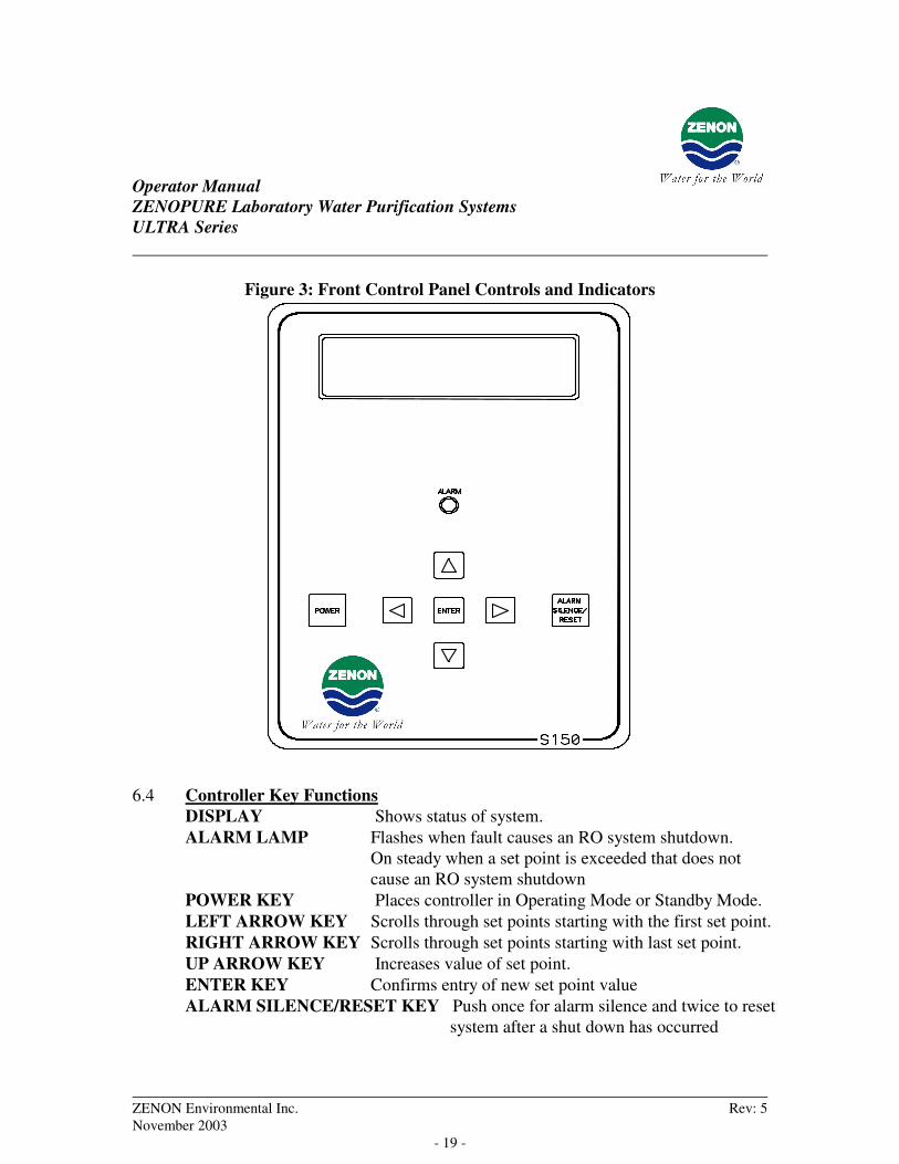
Figure 3: Front Control Panel Controls and Indicators
6.4 Controller Key Functions DISPLAY Shows status of system. ALARM LAMP Flashes when fault causes an RO system shutdown.
On steady when a set point is exceeded that does not cause an RO system shutdown
POWER KEY Places controller in Operating Mode or Standby Mode. LEFT ARROW KEY Scrolls through set points starting with the first set point. RIGHT ARROW KEY Scrolls through set points starting with last set point. UP ARROW KEY Increases value of set point. ENTER KEY Confirms entry of new set point value ALARM SILENCE/RESET KEY Push once for alarm silence and twice to reset
system after a shut down has occurred
Operator Manual ZENOPURE Laboratory Water Purification Systems ULTRA Series
ZENON Environmental Inc. Rev: 5 November 2003 - 20 -
7 SYSTEM OPERATION Prior to start-up, ensure that the system is plugged into a 120 VAC power source in order for it to operate. Please ensure that the environment is suitable for electrical connection. Ensure that all feedwater supply tubing is connected to the appropriate connection point on the system. Ensure that the RO concentrate tubing is directed to s suitable drain. NOTE: System feedwater pressure should be 30 psig for optimal performance. Maximum feedwater temperature is 35°C.
7.1 General Operation The unit has 2 modes of operation; STANDBY mode, and OPERATING mode. In STANDBY mode, the unit is effectively off. All outputs are turned off and the display shows STANDBY. The system is in the ready state to begin operation. The unit operates automatically in the OPERATING mode; both the RO pump and DI recirculation pump are enabled and will begin to operate in accordance with level switches and the low-pressure switch. All inputs are monitored and the outputs are controlled accordingly. Pressing the green button/key will switch the unit from STANDBY to OPERATING, or from OPERATING to STANDBY. If power is removed from the unit, and when power is reapplied, the unit will restart in the mode it was in when power was removed.
7.2 Display The display is a 2 line x 20-character backlit liquid crystal display. System operating status and sensor readings are shown on this display. Set point information is also shown on this display.
POWER

Operator Manual ZENOPURE Laboratory Water Purification Systems ULTRA Series
ZENON Environmental Inc. Rev: 5 November 2003 - 21 -
7.3 Operating Status Messages The operating status of the unit is shown on the top line of the display. The following list describes the items shown for the operating status.
STANDBY The unit is in the STANDBY mode. When the system is initially plugged in, STANDBY mode will be initiated. Pressing the green button will switch the system mode from STANDBY to OPERATING.
DELAY 5 The unit will start after a 5 second delay. The number is the
seconds remaining (5) before the RO pump starts. The 5-second delay is programmed to provide adequate purging of any air that may be present in the RO housing/vessel.
OPERATING
The system is in OPERATING mode. In OPERATING mode,
Reverse Osmosis (RO) and Deionized (DI) Ultrapure product water
will be produced. In OPERATING mode all system safety
interlocks are active. Pressing the green
button will switch the system mode from OPERATING to
STANDBY. Pressing the button again will cause the
system to switch back from STANDBY mode to OPERATING
mode.
TANK FULL The RO pump is in an idle condition due to an RO tank full
condition. The system will remain in this state until the water level in the RO reservoir has fallen below the intermediate level switch. Water level in the product water reservoir will decrease only if water is consumed through the RO product water valve (hand valve on front of tank) or if ULTRApure water is consumed from the ULTRApure water valve (hand valve located on the acrylic door).
POWER
POWER
POWER

Operator Manual ZENOPURE Laboratory Water Purification Systems ULTRA Series
ZENON Environmental Inc. Rev: 5 November 2003 - 22 -
PRESS FAULT
The unit is shut down due to a low-pressure fault condition. Low pressure has been sensed, the display will read PRESS FAULT, and the red ALARM light will flash on and off, and an audible alarm will sound with high decibel beep sounds. NOTE: The system has been programmed to re-start automatically after a 1-minute time delay. Following this delay, the system will attempt a re-start providing that there is sufficient pressure (>10 PSI) during the 5-second start delay. If no pressure is sensed during this start delay, the system will remain shut down in this fault condition
MEMB FLUSH 1
Membrane flush is active. The number is the minutes (1) remaining in the flush cycle. The flush cycle allows water that is under feedwater line pressure to pass through the system and flush out contaminants that may be depositing on the membrane(s). The flush helps to minimize bacterial contamination during non-operating times. During membrane flush mode, all permeate and concentrate is diverted to drain via the flush solenoid valve. NOTE: The membrane flush factory set point is to flush for 1 minute every 4 hours that the system is in OPERATING mode.
7.4 Operating Hours The current operating hours are shown on the bottom line. This is an important tool for helping to optimize and plan inventory tracking. For example, to track important information such as prefilter cartridge life, you can mark the “operating hour” value on a log sheet each time a new prefilter is installed in the system. Tracking this information may help determine cyclical trends in consumable use.
7.5 Temperature The current water temperature is shown on the bottom line after the operating hours. When the unit is offline because of a shut down condition, the display will continue to display the temperature. The displayed temperature can be displayed in either degrees Celsius or Fahrenheit. This is also important information to report on the log sheets and track over time. As water temperatures tend to decrease during the winter months, you

Operator Manual ZENOPURE Laboratory Water Purification Systems ULTRA Series
ZENON Environmental Inc. Rev: 5 November 2003 - 23 -
may notice that water production from the membrane also decreases. By recording the operating temperature, you can establish whether a trend exists or not, or allow for temperature compensation in determining membrane performance. NOTE: The maximum feedwater temperature allowed is 35°C.
7.6 Warning Messages Warning messages are also shown on the second line. If any warnings are active, the active warnings will alternate with the normal displays for the bottom line. The following lists the warning messages.
PRESS FAULT If feed water pressure is low (<10 psig) for a period greater than 3 seconds, the pressure switch will activate and a visual and audible alarm will be indicated with the banner PRESS FAULT showing on the display.
To silence the alarm, press the button once. To have the
system reinitiate a start, press the button a second time.
If the is not pressed within 60 seconds of an alarm condition, the controller will attempt an automatic restart of the RO pump. Only if the condition that originally caused the alarm has been corrected will the system be able to successfully restart.
LO RES ALRM
The product Resistivity has fallen below the acceptable limit as determined by the customer’s quality requirements and programmed as the set point. The factory set point is 10.0 MΩ. The system has a 60 second delay once it first reads the set point value before the alarm will initiate and the warning message appears.
ALARM SILENCE /
RESET ALARM
SILENCE / RESET
ALARM SILENCE /
RESET
Operator Manual ZENOPURE Laboratory Water Purification Systems ULTRA Series
ZENON Environmental Inc. Rev: 5 November 2003 - 24 -
The Resistivity monitor indicates the DI water in megohms (M). If the display reads “^^.^”, it means the value is over 19.9 M and typically occurs only if air is trapped within the probe, or that a calibration may be required. Prior to performing a calibration of the Resistivity probe, vent any air that may be trapped at the top of the DI bowls.
The audible and visual alarm can be silenced and switched off
temporarily by pressing the button once. This will
eliminate the alarm sound and light but it will not eliminate the
cause for the alarm condition. To eliminate the cause, the DI
cartridges must be replaced.
TANK LOW The RO water tank low-level switch input is activated and will turn
off the DI recirculation pump after a 5 second delay. The DI pump will be turned off to protect the DI recirculation pump from a lack of supply water in the reservoir. This condition will occur when the RO product water generation rate is less than the rate of the DI water consumption. With the DI pump “off” and the RO pump still “on”, the RO product reservoir will begin to fill.
During this condition, the alarm will be announced in a visual and
audible manner. The alarm can be silenced by pressing the
button once. Pressing the button again will reset the system. TANK LOW 2
This message indicates that the “tank low” input has cleared, and the reservoir tank is beginning to fill with RO water, and the DI pump will initiate once the count indicated on the panel is concluded. The number indicated on the panel is the time in minutes that are left in the delay to restart the DI recirculation pump.
ALARM SILENCE /
RESET
ALARM SILENCE /
RESET

Operator Manual ZENOPURE Laboratory Water Purification Systems ULTRA Series
ZENON Environmental Inc. Rev: 5 November 2003 - 25 -
HIGH TEMP DIVERT If the temperature of the recirculated DI water reaches the preprogrammed adjustable set point (Factory set point is 25º Celsius) “HIGH TEMP DIVERT” mode will be activated. A number will follow the displayed message indicating the number of minutes remaining in the divert cycle. (Factory set point is 20 minutes) The Red Alarm Light will also illuminate during High Temp Divert. During HIGH TEMP DIVERT, a solenoid valve at the base of the storage reservoir will open and slowly drain some of the contents of the tank. When the Tank Low Level switch is reached, cooler RO water will enter the tank, lowering the overall temperature in the DI recirculation loop. If the DI water temperature is below the set point at the end of the divert cycle, the system will return to normal OPERATING Mode. If the temperature in the DI loop is still above the set point upon completion of the divert cycle, HIGH TEMP DIVERT will continue. NOTE: DURING THE HIGH TEMP DIVERT MODE, THE SYSTEM WILL CONTINUE TO OPERATE NORMALLY.
7.7 Reservoir Conductivity Indicator The conductivity indicator for the RO water is located on the front of the reservoir. When the conductivity of the water in the reservoir is less than 20 µS/cm, the monitor light will illuminate green light. If the conductivity is greater than 20 µS/cm, the monitor light will illuminate a red light indicating that the water in the reservoir should be discarded.

Operator Manual ZENOPURE Laboratory Water Purification Systems ULTRA Series
ZENON Environmental Inc. Rev: 5 November 2003 - 26 -
8 GLOSSARY
8.1 Reverse Osmosis Specific Terms: Anions
Ions that are negatively charged.
Average Operating Pressure
Average of the module inlet and outlet pressures and expressed in PSI or kPa.
Concentrate
The portion of the feed that is rejected by the RO membrane. The concentrate flow is typically measured in either USGPM or liters/minute.
Module Flow rate
The fluid flow rate through the RO module in USGPM or liters/minute which is normally equal to the sum of the permeate and the concentrate flow rates.
Permeate
The membrane filtered (treated) water. The flow rate is generally expressed in either USGPM or liters/minute. Alternatively, for design purposes, permeate flux is expressed in either US gallons/ft2 of membrane area-day (USgfd) or liters/m2 of membrane area-hour (LMH).
CAP
College of American Pathologists
ASTM
American Society for Testing and Materials
NCCLS
National Committee for Clinical Laboratory Standards

Operator Manual ZENOPURE Laboratory Water Purification Systems ULTRA Series
ZENON Environmental Inc. Rev: 5 November 2003 - 27 -
9 TEMPERATURE EFFECTS
The table below shows the appropriate temperature correction factor to use based on the measured temperature of the feed water. The rate of permeate flow is directly related the temperature of the feedwater. As the feedwater temperature increases, the permeate rate from the RO and UF membranes will also increase.
To use this table, multiply the permeate rate measured from the unit by the “temperature correction” value of table for the temperature of the feedwater as indicated on the controller on the system. When speaking with ZENON Field Service Representatives, you should also provide temperature corrected permeate flow rates.
Table 4: Permeate Temperature Correction Factors (°C)
Feed water Temperature (°°°°C)
Correction Factor
Feed water Temperature (°°°°C)
Correction Factor
5 2.00 20 1.19 6 1.94 21 1.15 7 1.89 22 1.11 8 1.83 23 1.07 9 1.77 24 1.03 10 1.71 25 1.00 11 1.65 26 0.97 12 1.59 27 0.94 13 1.53 28 0.91 14 1.47
29 0.88 15 1.42 30 0.85 16 1.37 32 0.81 17 1.32 34 0.77 18 1.27 36 0.72 19 1.23 38 0.67
EXAMPLE: If the product flow rate at 25ºC is 1500 gallons/day, what is the product flow rate at 15ºC? Answer: Temperature correction factor at 15ºC (from table) = 1.42 1500 ÷ 1.42 = 1056 gallons/day

Operator Manual ZENOPURE Laboratory Water Purification Systems ULTRA Series
ZENON Environmental Inc. Rev: 5 November 2003 - 28 -
10 ORDERING SPARES AND CONSUMABLES Your system has been designed with reliability and performance in mind. The system has been built with most reliable and relevant parts and consumable parts. Following is a list of common parts and consumables that may be required from time to time. Please contact ZENON directly prior to ordering. We will be happy to review your operating situation with you to verify if these parts are necessary to order. When you are ready to place your order, contact our Service Department at ZENON at (905) 465-3030 or send your fax to our Service Department at (905) 465-3050.
Part # Description 1010056 5 µ carbon impregnated prefilter cartridge, 10” 1010006 5 µ prefilter cartridge, 10” 1010058 Mixed bed DI cartridge column, 20” 1001065 0.2 micron final bacteria filter 1004014 0.2 micron tank vent filter 1011195 (ULTRA 35 & 70)
Reverse osmosis membrane element, 2.5”∅ x 21”L
1000522 (ULTRA 150)
Reverse osmosis membrane element, 4.0”∅ x 21”L
1000684 Ultrafiltration membrane element, 2”∅ x 12”L 8010092 ZENON cleaner chemical MC-1 (acid) 8010741 ZENON cleaner chemical MC- 4 (caustic) 8010109 ZENON sanitizing chemical MP- 4
Operator Manual ZENOPURE Laboratory Water Purification Systems ULTRA Series
ZENON Environmental Inc. Rev: 5 November 2003 - 29 -
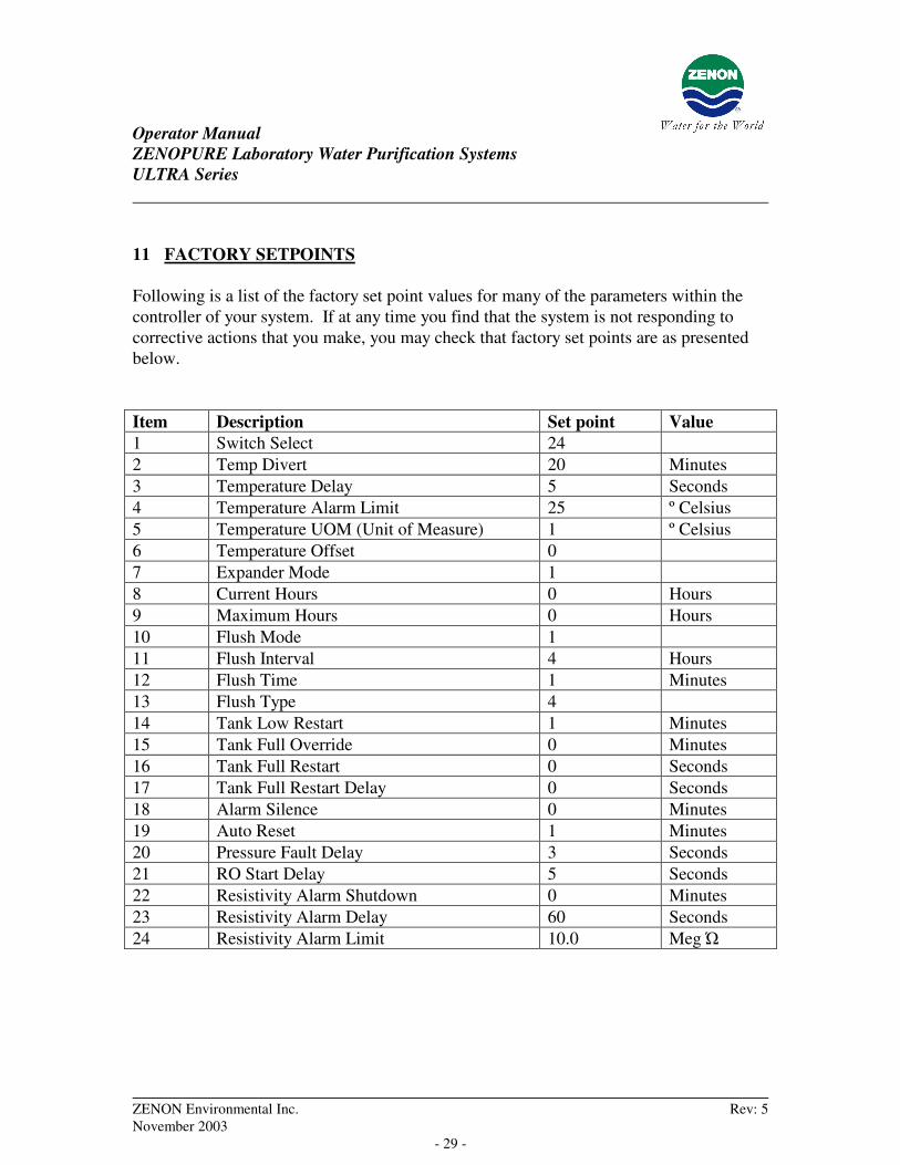
11 FACTORY SETPOINTS Following is a list of the factory set point values for many of the parameters within the controller of your system. If at any time you find that the system is not responding to corrective actions that you make, you may check that factory set points are as presented below. Item Description Set point Value 1 Switch Select 24 2 Temp Divert 20 Minutes 3 Temperature Delay 5 Seconds 4 Temperature Alarm Limit 25 º Celsius 5 Temperature UOM (Unit of Measure) 1 º Celsius 6 Temperature Offset 0 7 Expander Mode 1 8 Current Hours 0 Hours 9 Maximum Hours 0 Hours 10 Flush Mode 1 11 Flush Interval 4 Hours 12 Flush Time 1 Minutes 13 Flush Type 4 14 Tank Low Restart 1 Minutes 15 Tank Full Override 0 Minutes 16 Tank Full Restart 0 Seconds 17 Tank Full Restart Delay 0 Seconds 18 Alarm Silence 0 Minutes 19 Auto Reset 1 Minutes 20 Pressure Fault Delay 3 Seconds 21 RO Start Delay 5 Seconds 22 Resistivity Alarm Shutdown 0 Minutes 23 Resistivity Alarm Delay 60 Seconds 24 Resistivity Alarm Limit 10.0 Meg

Operator Manual ZENOPURE Laboratory Water Purification Systems ULTRA Series
ZENON Environmental Inc. Rev: 5 November 2003 - 30 -
12 THEORY OF OPERATION
12.1 Filtration Spectrum Filtration is defined as the separation of a compound from a fluid stream. In conventional usage, it usually refers to the separation of solid, insoluble particles from liquid or gaseous streams. Membrane filtration extends this application further to include the separation of dissolved solids in liquid streams and hence, membrane processes in water treatment are commonly used to remove various materials ranging from salts to microorganisms. The most commonly employed membrane processes and the filtration ranges in which they operate, are presented in the chart below.
Membrane processes can be categorized in various, related methods, three of which are: their pore size, their molecular weight cutoff, or the pressure at which they operate. The water treatment objectives will determine the basis on which a process is selected.
RelativeSize of Common
Materials
ApproximateMolecular Weight
Angstorm Units(Log Scale)
Micrometers(Log Scale)
ST Microscope
Ionic Range
0.001 0.01 0.1 1.0 10 100 1000
107
106
105
104
103
102
101
100
Reverse Osmosis
Nanofiltration
Ultrafiltration
Microfiltration
Particle Filtration
200 1000 10,000 20,000 100,000 500,000
Molecular Range Macro MolecularRange
Micro Molecular Range
Scanning Electron Microscope Optical Microscope Visble to Naked Eye
Macro Particle Range
Processfor
Separation
Aqueous Salt Carbon Black
Endotoxin/Pyrogen
Paint Pigment
Cryptosporidium
GiardiaCyst
Human Hair
Beach Sand
Mist
Yeast Cell
Bacteria
Coal Dust
RedBloodCellBlue Indigo Dye
Tobacco Smoke
Gelatin
Metallon Synth.Dye
Virus
PinPoint
Pollen
A.C. Fine Test Dust
Latex/Emulsion
GranularActivatedCarbon
Colloidal Silica
Asbestos Milled Flour
AtomicRadius
Sugar
Albumin Protein
Figure 10-1 Filtration Spectrum

Operator Manual ZENOPURE Laboratory Water Purification Systems ULTRA Series
ZENON Environmental Inc. Rev: 5 November 2003 - 31 -
12.2 Reverse Osmosis: An Introduction
Reverse Osmosis (RO) is a pressure-induced reversal of the natural flow phenomenon of osmosis. Osmosis is the spontaneous passage of a liquid through a semi-permeable membrane from a dilute to a more concentrated solution (see Figure 3-2 below). The driving force is osmotic pressure, which is a function of the type of solvent and solute and the concentration. When the osmotic pressure is offset, as illustrated in the middle panel of Figure 3-2, the result is osmotic equilibrium - the net flow across the membrane is zero. Applying an excess of pressure on the concentrated side results in reverse osmosis, where flow is from the concentrated side to the dilute side.
PI
Figure 10-2 Reverse Osmosis
ZENON Reverse Osmosis systems utilize strong, durable, spiral wound reverse osmosis elements for separation. The process involves pumping pretreated feedwater under pressure into the reverse osmosis membranes. The membranes then separate the feed stream into a 'purified' product stream (called Permeate) and a concentrate stream (called Concentrate), in which the bulk of the mineral salts, bacteria etc. from the feed stream are now located. Hence, the concentration of these 'contaminants' will be substantially

Operator Manual ZENOPURE Laboratory Water Purification Systems ULTRA Series
ZENON Environmental Inc. Rev: 5 November 2003 - 32 -
higher in the concentrate stream than in the original feed stream. A schematic illustrating the separation of the feed stream is as follows:
Figure 10-3 Reverse Osmosis
An illustration of a spiral wound membrane module is shown below. The module contains two layers of semi permeable membrane separated by a porous, woven fabric support. Three edges of the membranes are sealed to form an envelope around the porous support. The fourth edge of the membrane envelope is attached to a perforated tube. A sheet of plastic mesh is placed in one side of the membrane envelope, which is wrapped around the central perforated tube in a spiral fashion. The mesh separates the membrane layers and acts as a turbulence promoter. The spiral wound element is inserted into a cylindrical pressure vessel to form a completed membrane module or cartridge.

Operator Manual ZENOPURE Laboratory Water Purification Systems ULTRA Series
ZENON Environmental Inc. Rev: 5 November 2003 - 33 -
Anti-Telescoping Device
Concentrate
Permeate
Perforated CentralTube
Feed Solution
Carrier Material
Sealed Edge(glue)
Outer Layer SpacerMaterial
Membrane
Feed ChannelSpacer
Membrane Backing Material
Permeate Flow(after passing thru membrane)
Figure 10-4 Spiral Wound Module Design
The feed solution is introduced into the module at one end of the spiral wound roll and flows along the inter-membrane gap created by the mesh. Some of the pressurized feed permeates the membrane into the inside of the membrane envelope and follows the flow channels in the fabric support that direct the permeate the central perforated tube for collection. The concentrate, flows out the end of the module opposite to where the feed is introduced.

Operator Manual ZENOPURE Laboratory Water Purification Systems ULTRA Series
ZENON Environmental Inc. Rev: 5 November 2003 - 34 -
13 SYSTEM COMMISSIONING SETPOINTS Once the system has been commissioned, the parameters or values should be recorded in the table below. Once completed, the following list may or may not differ from the values listed in the table on page 29 of this manual. These commissioning parameters can be used as a future reference as the original or default parameters. Item Description Set point Value 1 Switch Select 2 Temp Divert Minutes 3 Temperature Delay Seconds 4 Temperature Alarm Limit º Celsius 5 Temperature UOM (Unit of Measure) º Celsius 6 Temperature Offset 7 Expander Mode 8 Current Hours Hours 9 Maximum Hours Hours 10 Flush Mode 11 Flush Interval Hours 12 Flush Time Minutes 13 Flush Type 14 Tank Low Restart Minutes 15 Tank Full Override Minutes 16 Tank Full Restart Seconds 17 Tank Full Restart Delay Seconds 18 Alarm Silence Minutes 19 Auto Reset Minutes 20 Pressure Fault Delay Seconds 21 RO Start Delay Seconds 22 Resistivity Alarm Shutdown Minutes 23 Resistivity Alarm Delay Seconds 24 Resistivity Alarm Limit Meg