Embed Size (px)
Citation preview

TIG MODULE
Operator’s Manual
Save for future reference
Date Purchased
Code: (ex: 10859)
Serial: (ex: U1060512345)
5
10
15
20
2530
35
40
45
50
55 S
CONTINUOUS
OFF
POWER
2
AFTERFLOW
MODEL CODE SERIAL NO.
THE LINCOLN ELECTRIC CO. CLEVELAND, OHIO U.S.A.
INPUT
PORTABLE HI-FREQ
WARNING
OFF
O
ON
L9440
1
HIGH FREQUENCY
LOCAL
115 V 1.3 A 50/60 Hz
0
1
2
3
45
6
7
8
9
10
CURRENTCONTROL
SWITCH
TM
CURRENT CONTROL
REMOTE AMPTROL
HF
START ONLY
20%
350A
60% 100%
250A 180A
RATED CAPACITY
20A TO 350A
IM528-B | Issue D ate 7-Feb
© Lincoln Global, Inc. All Rights Reserved.
For use with machines having Code Numbers:
10135, 10203, 10284, 11010
Register your machine: www.lincolnelectric.com/register
Authorized Service and Distributor Locator: www.lincolnelectric.com/locator
TIG MODULE - i -
iSAFETYi
ARC WELDING CAN BE HAZARDOUS. PROTECT YOURSELF AND OTHERS FROM POSSIBLE SERIOUS INJURY OR DEATH.KEEP CHILDREN AWAY. PACEMAKER WEARERS SHOULD CONSULT WITH THEIR DOCTOR BEFORE OPERATING.
Read and understand the following safety highlights. For additional safety information, it is strongly recommended that youpurchase a copy of “Safety in Welding & Cutting - ANSI Standard Z49.1” from the American Welding Society, P.O. Box351040, Miami, Florida 33135 or CSA Standard W117.2-1974. A Free copy of “Arc Welding Safety” booklet E205 is availablefrom the Lincoln Electric Company, 22801 St. Clair Avenue, Cleveland, Ohio 44117-1199.
BE SURE THAT ALL INSTALLATION, OPERATION, MAINTENANCE AND REPAIR PROCEDURES AREPERFORMED ONLY BY QUALIFIED INDIVIDUALS.
WARNING
Mar ‘95
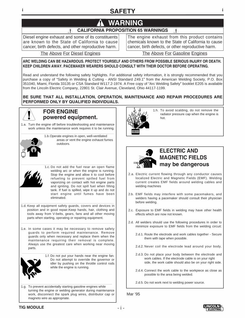
ELECTRIC AND MAGNETIC FIELDSmay be dangerous
2.a. Electric current flowing through any conductor causes localized Electric and Magnetic Fields (EMF). Welding current creates EMF fields around welding cables and welding machines
2.b. EMF fields may interfere with some pacemakers, andwelders having a pacemaker should consult their physicianbefore welding.
2.c. Exposure to EMF fields in welding may have other healtheffects which are now not known.
2.d. All welders should use the following procedures in order tominimize exposure to EMF fields from the welding circuit:
2.d.1. Route the electrode and work cables together - Securethem with tape when possible.
2.d.2. Never coil the electrode lead around your body.
2.d.3. Do not place your body between the electrode andwork cables. If the electrode cable is on your right side, the work cable should also be on your right side.
2.d.4. Connect the work cable to the workpiece as close aspossible to the area being welded.
2.d.5. Do not work next to welding power source.
1.h. To avoid scalding, do not remove theradiator pressure cap when the engine ishot.
CALIFORNIA PROPOSITION 65 WARNINGS
Diesel engine exhaust and some of its constituentsare known to the State of California to causecancer, birth defects, and other reproductive harm.
The engine exhaust from this product containschemicals known to the State of California to causecancer, birth defects, or other reproductive harm.
The Above For Diesel Engines The Above For Gasoline Engines
FOR ENGINEpowered equipment.
1.a. Turn the engine off before troubleshooting and maintenancework unless the maintenance work requires it to be running.
____________________________________________________1.b.Operate engines in open, well-ventilated
areas or vent the engine exhaust fumes outdoors.
____________________________________________________1.c. Do not add the fuel near an open flame
welding arc or when the engine is running.Stop the engine and allow it to cool beforerefueling to prevent spil led fuel fromvaporizing on contact with hot engine partsand igniting. Do not spill fuel when fillingtank. If fuel is spilled, wipe it up and do notstart engine unti l fumes have beeneliminated.
____________________________________________________1.d. Keep all equipment safety guards, covers and devices in
position and in good repair.Keep hands, hair, clothing andtools away from V-belts, gears, fans and all other movingparts when starting, operating or repairing equipment.
____________________________________________________
1.e. In some cases it may be necessary to remove safetyguards to perform required maintenance. Removeguards only when necessary and replace them when themaintenance requiring their removal is complete.Always use the greatest care when working near movingparts.
___________________________________________________1.f. Do not put your hands near the engine fan.
Do not attempt to override the governor oridler by pushing on the throttle control rodswhile the engine is running.
___________________________________________________1.g. To prevent accidentally starting gasoline engines while
turning the engine or welding generator during maintenancework, disconnect the spark plug wires, distributor cap ormagneto wire as appropriate.

TIG MODULE- ii -
iiSAFETYii
ARC RAYS can burn.4.a. Use a shield with the proper filter and cover
plates to protect your eyes from sparks andthe rays of the arc when welding or observingopen arc welding. Headshield and filter lensshould conform to ANSI Z87. I standards.
4.b. Use suitable clothing made from durable flame-resistantmaterial to protect your skin and that of your helpers fromthe arc rays.
4.c. Protect other nearby personnel with suitable, non-flammablescreening and/or warn them not to watch the arc nor exposethemselves to the arc rays or to hot spatter or metal.
ELECTRIC SHOCK cankill.3.a. The electrode and work (or ground) circuits
are electrically “hot” when the welder is on.Do not touch these “hot” parts with your bareskin or wet clothing. Wear dry, hole-freegloves to insulate hands.
3.b. Insulate yourself from work and ground using dry insulation.Make certain the insulation is large enough to cover your fullarea of physical contact with work and ground.
In addition to the normal safety precautions, if weldingmust be performed under electrically hazardousconditions (in damp locations or while wearing wetclothing; on metal structures such as floors, gratings orscaffolds; when in cramped positions such as sitting,kneeling or lying, if there is a high risk of unavoidable oraccidental contact with the workpiece or ground) usethe following equipment:
• Semiautomatic DC Constant Voltage (Wire) Welder.• DC Manual (Stick) Welder.• AC Welder with Reduced Voltage Control.
3.c. In semiautomatic or automatic wire welding, the electrode,electrode reel, welding head, nozzle or semiautomaticwelding gun are also electrically “hot”.
3.d. Always be sure the work cable makes a good electricalconnection with the metal being welded. The connectionshould be as close as possible to the area being welded.
3.e. Ground the work or metal to be welded to a good electrical(earth) ground.
3.f. Maintain the electrode holder, work clamp, welding cable andwelding machine in good, safe operating condition. Replacedamaged insulation.
3.g. Never dip the electrode in water for cooling.
3.h. Never simultaneously touch electrically “hot” parts ofelectrode holders connected to two welders because voltagebetween the two can be the total of the open circuit voltageof both welders.
3.i. When working above floor level, use a safety belt to protectyourself from a fall should you get a shock.
3.j. Also see Items 6.c. and 8.
FUMES AND GASEScan be dangerous.5.a. Welding may produce fumes and gases
hazardous to health. Avoid breathing thesefumes and gases.When welding, keepyour head out of the fume. Use enoughventilation and/or exhaust at the arc to keep
fumes and gases away from the breathing zone. Whenwelding with electrodes which require specialventilation such as stainless or hard facing (seeinstructions on container or MSDS) or on lead orcadmium plated steel and other metals or coatingswhich produce highly toxic fumes, keep exposure aslow as possible and below Threshold Limit Values (TLV)using local exhaust or mechanical ventilation. Inconfined spaces or in some circumstances, outdoors, arespirator may be required. Additional precautions arealso required when welding on galvanized steel.
5.b. Do not weld in locations near chlorinated hydrocarbon vaporscoming from degreasing, cleaning or spraying operations.
The heat and rays of the arc can react with solvent vapors toform phosgene, a highly toxic gas, and other irritating products.
5.c. Shielding gases used for arc welding can displace air andcause injury or death. Always use enough ventilation,especially in confined areas, to insure breathing air is safe.
5.d. Read and understand the manufacturer’s instructions for thisequipment and the consumables to be used, including thematerial safety data sheet (MSDS) and follow youremployer’s safety practices. MSDS forms are available fromyour welding distributor or from the manufacturer.
5.e. Also see item 1.b. Mar ‘95
TIG MODULE - iii -
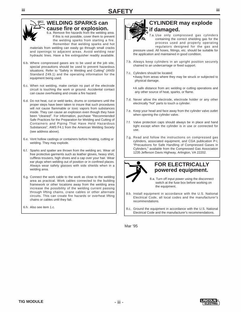
FOR ELECTRICALLYpowered equipment.
8.a. Turn off input power using the disconnectswitch at the fuse box before working onthe equipment.
8.b. Install equipment in accordance with the U.S. NationalElectrical Code, all local codes and the manufacturer’srecommendations.
8.c. Ground the equipment in accordance with the U.S. NationalElectrical Code and the manufacturer’s recommendations.
CYLINDER may explodeif damaged.7.a. Use only compressed gas cylinders
containing the correct shielding gas for theprocess used and properly operatingregulators designed for the gas and
pressure used. All hoses, fittings, etc. should be suitable forthe application and maintained in good condition.
7.b. Always keep cylinders in an upright position securelychained to an undercarriage or fixed support.
7.c. Cylinders should be located:• Away from areas where they may be struck or subjected tophysical damage.
• A safe distance from arc welding or cutting operations andany other source of heat, sparks, or flame.
7.d. Never allow the electrode, electrode holder or any otherelectrically “hot” parts to touch a cylinder.
7.e. Keep your head and face away from the cylinder valve outletwhen opening the cylinder valve.
7.f. Valve protection caps should always be in place and handtight except when the cylinder is in use or connected foruse.
7.g. Read and follow the instructions on compressed gascylinders, associated equipment, and CGA publication P-l,“Precautions for Safe Handling of Compressed Gases inCylinders,” available from the Compressed Gas Association1235 Jefferson Davis Highway, Arlington, VA 22202.
iiiSAFETYiii
Mar ‘95
WELDING SPARKS cancause fire or explosion.6.a. Remove fire hazards from the welding area.
If this is not possible, cover them to preventthe welding sparks from starting a fire.Remember that welding sparks and hot
materials from welding can easily go through small cracksand openings to adjacent areas. Avoid welding nearhydraulic lines. Have a fire extinguisher readily available.
6.b. Where compressed gases are to be used at the job site,special precautions should be used to prevent hazardoussituations. Refer to “Safety in Welding and Cutting” (ANSIStandard Z49.1) and the operating information for theequipment being used.
6.c. When not welding, make certain no part of the electrodecircuit is touching the work or ground. Accidental contactcan cause overheating and create a fire hazard.
6.d. Do not heat, cut or weld tanks, drums or containers until theproper steps have been taken to insure that such procedureswill not cause flammable or toxic vapors from substancesinside. They can cause an explosion even though they havebeen “cleaned”. For information, purchase “RecommendedSafe Practices for the Preparation for Welding and Cutting ofContainers and Piping That Have Held HazardousSubstances”, AWS F4.1 from the American Welding Society(see address above).
6.e. Vent hollow castings or containers before heating, cutting orwelding. They may explode.
6.f. Sparks and spatter are thrown from the welding arc. Wear oilfree protective garments such as leather gloves, heavy shirt,cuffless trousers, high shoes and a cap over your hair. Wearear plugs when welding out of position or in confined places.Always wear safety glasses with side shields when in awelding area.
6.g. Connect the work cable to the work as close to the weldingarea as practical. Work cables connected to the buildingframework or other locations away from the welding areaincrease the possibility of the welding current passingthrough lifting chains, crane cables or other alternatecircuits. This can create fire hazards or overheat liftingchains or cables until they fail.
6.h. Also see item 1.c.

TIG MODULE- iv -
ivSAFETYiv
PRÉCAUTIONS DE SÛRETÉPour votre propre protection l ire et observer toutes lesinstructions et les précautions de sûreté specifiques quiparraissent dans ce manuel aussi bien que les précautions desûreté générales suivantes:
Sûreté Pour Soudage A L’Arc1. Protegez-vous contre la secousse électrique:
a. Les circuits à l’électrode et à la piéce sont sous tensionquand la machine à souder est en marche. Eviter toujourstout contact entre les parties sous tension et la peau nueou les vétements mouillés. Porter des gants secs et sanstrous pour isoler les mains.
b. Faire trés attention de bien s’isoler de la masse quand onsoude dans des endroits humides, ou sur un planchermetallique ou des grilles metalliques, principalement dans
les positions assis ou couché pour lesquelles unegrande partie du corps peut être en contact avec lamasse.
c. Maintenir le porte-électrode, la pince de masse, le câblede soudage et la machine à souder en bon et sûr étatdefonctionnement.
d.Ne jamais plonger le porte-électrode dans l’eau pour lerefroidir.
e. Ne jamais toucher simultanément les parties sous tensiondes porte-électrodes connectés à deux machines àsouder parce que la tension entre les deux pinces peutêtre le total de la tension à vide des deux machines.
f. Si on utilise la machine à souder comme une source decourant pour soudage semi-automatique, ces precautionspour le porte-électrode s’applicuent aussi au pistolet desoudage.
2. Dans le cas de travail au dessus du niveau du sol, seprotéger contre les chutes dans le cas ou on recoit un choc.Ne jamais enrouler le câble-électrode autour de n’importequelle partie du corps.
3. Un coup d’arc peut être plus sévère qu’un coup de soliel,donc:
a. Utiliser un bon masque avec un verre filtrant appropriéainsi qu’un verre blanc afin de se protéger les yeux durayonnement de l’arc et des projections quand on soudeou quand on regarde l’arc.
b. Porter des vêtements convenables afin de protéger lapeau de soudeur et des aides contre le rayonnement del‘arc.
c. Protéger l’autre personnel travaillant à proximité ausoudage à l ’aide d ’écrans appropriés et non-inflammables.
4. Des gouttes de laitier en fusion sont émises de l’arc desoudage. Se protéger avec des vêtements de protectionlibres de l’huile, tels que les gants en cuir, chemise épaisse,pantalons sans revers, et chaussures montantes.
5. Toujours porter des lunettes de sécurité dans la zone desoudage. Utiliser des lunettes avec écrans lateraux dans leszones où l’on pique le laitier.
6. Eloigner les matériaux inflammables ou les recouvrir afin deprévenir tout risque d’incendie dû aux étincelles.
7. Quand on ne soude pas, poser la pince à une endroit isolé dela masse. Un court-circuit accidental peut provoquer unéchauffement et un risque d’incendie.
8. S’assurer que la masse est connectée le plus prés possiblede la zone de travail qu’il est pratique de le faire. Si on placela masse sur la charpente de la construction ou d’autresendroits éloignés de la zone de travail, on augmente le risquede voir passer le courant de soudage par les chaines delevage, câbles de grue, ou autres circuits. Cela peutprovoquer des risques d’incendie ou d’echauffement deschaines et des câbles jusqu’à ce qu’ils se rompent.
9. Assurer une ventilation suffisante dans la zone de soudage.Ceci est particuliérement important pour le soudage de tôlesgalvanisées plombées, ou cadmiées ou tout autre métal quiproduit des fumeés toxiques.
10. Ne pas souder en présence de vapeurs de chlore provenantd’opérations de dégraissage, nettoyage ou pistolage. Lachaleur ou les rayons de l’arc peuvent réagir avec lesvapeurs du solvant pour produire du phosgéne (gasfortement toxique) ou autres produits irritants.
11. Pour obtenir de plus amples renseignements sur la sûreté,voir le code “Code for safety in welding and cutting” CSAStandard W 117.2-1974.
PRÉCAUTIONS DE SÛRETÉ POURLES MACHINES À SOUDER ÀTRANSFORMATEUR ET ÀREDRESSEUR
1. Relier à la terre le chassis du poste conformement au codede l’électricité et aux recommendations du fabricant. Ledispositif de montage ou la piece à souder doit être branchéà une bonne mise à la terre.
2. Autant que possible, I’installation et l’entretien du posteseront effectués par un électricien qualifié.
3. Avant de faires des travaux à l ’ interieur de poste, ladebrancher à l’interrupteur à la boite de fusibles.
4. Garder tous les couvercles et dispositifs de sûreté à leurplace.
Mar. ‘93

TIG MODULE - v -
vv
Thank You for selecting a QUALITY product by Lincoln Electric. We want youto take pride in operating this Lincoln Electric Company product••• as much pride as we have in bringing this product to you!
Read this Operators Manual completely before attempting to use this equipment. Save this manual and keep ithandy for quick reference. Pay particular attention to the safety instructions we have provided for your protection.The level of seriousness to be applied to each is explained below:
WARNINGThis statement appears where the information must be followed exactly to avoid serious personal injury orloss of life.
This statement appears where the information must be followed to avoid minor personal injury or damage tothis equipment.
CAUTION
Please Examine Carton and Equipment For Damage ImmediatelyWhen this equipment is shipped, title passes to the purchaser upon receipt by the carrier. Consequently, Claimsfor material damaged in shipment must be made by the purchaser against the transportation company at thetime the shipment is received.
Please record your equipment identification information below for future reference. This information can befound on your machine nameplate.
Product _________________________________________________________________________________
Model Number ___________________________________________________________________________
Code Number or Date Code_________________________________________________________________
Serial Number____________________________________________________________________________
Date Purchased___________________________________________________________________________
Where Purchased_________________________________________________________________________
Whenever you request replacement parts or information on this equipment, always supply the information youhave recorded above. The code number is especially important when identifying the correct replacement parts.
On-Line Product Registration
- Register your machine with Lincoln Electric either via fax or over the Internet.
• For faxing: Complete the form on the back of the warranty statement included in the literature packetaccompanying this machine and fax the form per the instructions printed on it.
• For On-Line Registration: Go to our WEB SITE at www.lincolnelectric.com. Choose “Quick Links” and then“Product Registration”. Please complete the form and submit your registration.

TABLE OF CONTENTS
Page
Safety .....................................................................................................................i-iv
Installation................................................................................................................1-17Technical Specifications ............................................................................................1
Input and Rated CapacitiesRecommended Welding CablesPhysical Dimensions
Location .....................................................................................................................2Environmental Protection...........................................................................................2High Frequency Interference Protection ....................................................................2Supply Connections ...................................................................................................3Input & Output Connections.......................................................................................3Installation of Field Installed Accessories ..................................................................4Installation with a Power Source...........................................................................5-17
Ranger 8 Installation...........................................................................................5-8Ranger 9 Installation.........................................................................................9-10Ranger 10 & Ranger 300 D Installation ..........................................................11-12Ranger 10-LX & Ranger 300 DLX Installation ................................................13-14Installation with other Lincoln Power Sources ................................................15-17
Operation................................................................................................................18-30Safety Instructions ...................................................................................................18Graphic Symbols......................................................................................................19Product Description..................................................................................................20Recommended Processes and Equipment..............................................................20Design Summary .....................................................................................................20Controls and Settings .........................................................................................21-22Ranger 8 Operation ............................................................................................23-24Figure 9....................................................................................................................25Ranger 9 Operation .................................................................................................26Ranger 10 & Ranger 300 D Operation.....................................................................27Ranger 10-LX & Ranger 300 DLX Operation...........................................................28Operation on other Lincoln Power Sources.............................................................29TIG Welding Information ..........................................................................................30
Accessories.................................................................................................................31
Maintenance ................................................................................................................32Safety Precautions...................................................................................................32Periodic Maintenance ..............................................................................................32
Troubleshooting ....................................................................................................33-36How To Use Troubleshooting Guide........................................................................33Troubleshooting Guide .......................................................................................34-36
Wiring Diagram ...........................................................................................................37
Parts Manual ...................................................................................................Appendix
TIG MODULE- vi -

INSTALLATIONTECHNICAL SPECIFICATIONS - TIG MODULE
CodeNumber
10135102031028411010
Total Capacity Range
15 - 400 amps AC/DC
Input Current
1.3 amperes
Amps200 amps AC/DC
300 amps AC/DC
400 amps AC/DC
StandardVoltage
115 VAC 50/60(60VAC TO 130 VAC) 50/60 HZ.
(MIN. TO MAX.)
Duty Cycle100%
60%
20%
Duty Cycle
100%
60%
20%
Amps
200 amps AC/DC
300 amps AC/DC
400 amps AC/DC
Cable sizes* (mm2)
#2 AWG (30)
#1 AWG (35)
#1/0 AWG (50)
INPUT - SINGLE PHASE ONLY
RATED CAPACITIES
RECOMMENDED WELDING CABLES
Height Width Depth Weight
12.0 in. 15.0 in. 10.5 in. 33 lbs
305 mm 381 mm 267 mm (15 kg)
PHYSICAL DIMENSIONS
(*) Correct Cable size if the cable length is 150 feet (45.7 meters) or less.
Insulation Class 155(F)
– 1 –TIG MODULE

– 2 –
INSTALLATION
TIG MODULE
Read entire installation section before startinginstallation.
Safety Precautions
Users should familiarize themselves with Figure 8,Rear Connections, in the Operating Section of thismanual before proceeding.
LOCATION
The TIG Module can be mounted in or carried to anyconvenient location. It is designed to be portable. Ifplaced on the roof of engine welders, it must bemounted securely. A Docking Kit option is availablefor this purpose. See the Accessories section.
ENVIRONMENTAL PROTECTION
This accessory qualifies for an IP23 rating. It is suitedfor use in damp, dirty and dusty locations. (Inlocations where there are large amounts of conductivemetal or salt particles in the air, addit ionalmaintenance may be required.) It is protected againstrainfall. Excessive moisture can, however, causeshort term operational difficulties. Difficulties canoccur with the spark gap; it may not “spark” when theunit is first turned on after prolonged exposure tomoisture. Usually, allowing the unit to operate for 5 to15 minutes will allow the spark gap to dry out, andreturn to normal operation.
HIGH FREQUENCY INTERFERENCEPROTECTION
Since the spark gap oscillator in the TIG Module issimilar to a radio transmitter, improper installation canresult in radio and TV interference or problems withnearby electronic equipment.
Radiated interference can develop in the followingfour ways:1. Direct interference radiated from the welder and
the TIG Module.
ELECTRIC SHOCK can kill.
• Only qualified personnel should performthis installation.
• Turn the Power Source input power OFFat the disconnect switch or stop theengine before attempting to connect theTIG Module
• Do not touch electrically hot parts.
2. Direct interference radiated from the welding leads.
3. Direct interference radiated from feedback into thepower lines.
4. Interference from reradiation of “pickup” byungrounded metallic objects.
Keeping these contributing factors in mind, installingequipment per the following instructions shouldminimize problems.
1. Keep the power source input supply lines as shortas possible and completely enclose them in rigidmetallic conduit or equivalent shielding for aminimum distance of 50 feet (15.2 m). Thereshould be good electrical contact between thisconduit and the welder. Both ends of the conduitshould be connected to a driven ground and theentire length should be continuous.
2. Keep the work and electrode leads as short aspossible and as close together as possible.Lengths should not exceed 25 feet (7.6 m). Tapethe leads together when practical.
3. Be sure the torch and work cable rubber coveringsare free of cuts and cracks that allow highfrequency leakage. Cables with high naturalrubber content, such as Lincoln Stable-Arc® betterresist high frequency leakage than neoprene andother synthetic rubber insulated cables.
4. Keep the torch in good repair and all connectionstight to reduce high frequency leakage.
5. The work terminal must be connected to a groundwithin ten feet of the welder, using one of thefollowing methods:
a) A metal underground water pipe in directcontact with the earth for ten feet or more.
b) A 3/4” (19 mm) galvanized pipe or conduitor a 5/8” (16 mm) solid galvanized iron orsteel or copper rod driven at least eightfeet into the ground.
The ground should be securely made and thegrounding cable should be as short as possible usingcable of the same size as the work cable, or larger.Grounding to the building frame electrical conduit or along pipe system can result in reradiation, effectivelymaking these members radiating antennas.
NOTE: The welder frame MUST also be grounded.The work terminal ground does not groundthe welder frame.
WARNING
INSTALLATION
– 3 –TIG MODULE
6. Keep all access panels and covers securely inplace.
7. All electrical conductors within 50 feet (15.2 m) ofthe welder should be enclosed in grounded rigidmetallic conduit or equivalent shielding. Flexiblehelically-wrapped metallic conduit is generally notsuitable.
8. When the welder is enclosed in a metal building,several good earth driven electrical grounds (as in5 (b)) around the periphery of the building arerecommended.
SUPPLY CONNECTIONS
Control cables are needed to connect the TIGModule’s 9-pin Input Receptacle to the power source.Four different cables are available. The proper choiceof cable depends on the power source being used.Included in this report are charts which specify whichcable is used with a particular power source. Thecables come in standard 5 ft.(1.5m) lengths. 22(6.7m)and 45(13.7) ft. extensions are available.
Input power should be nominally 115 volts AC, but theTIG Module will operate properly on any AC voltagefrom 60 to 130 volts, 50 or 60 Hz. Input current drawis 1.3 amps at 115 volts.
INPUT AND OUTPUT CONNECTIONS
Input Connections
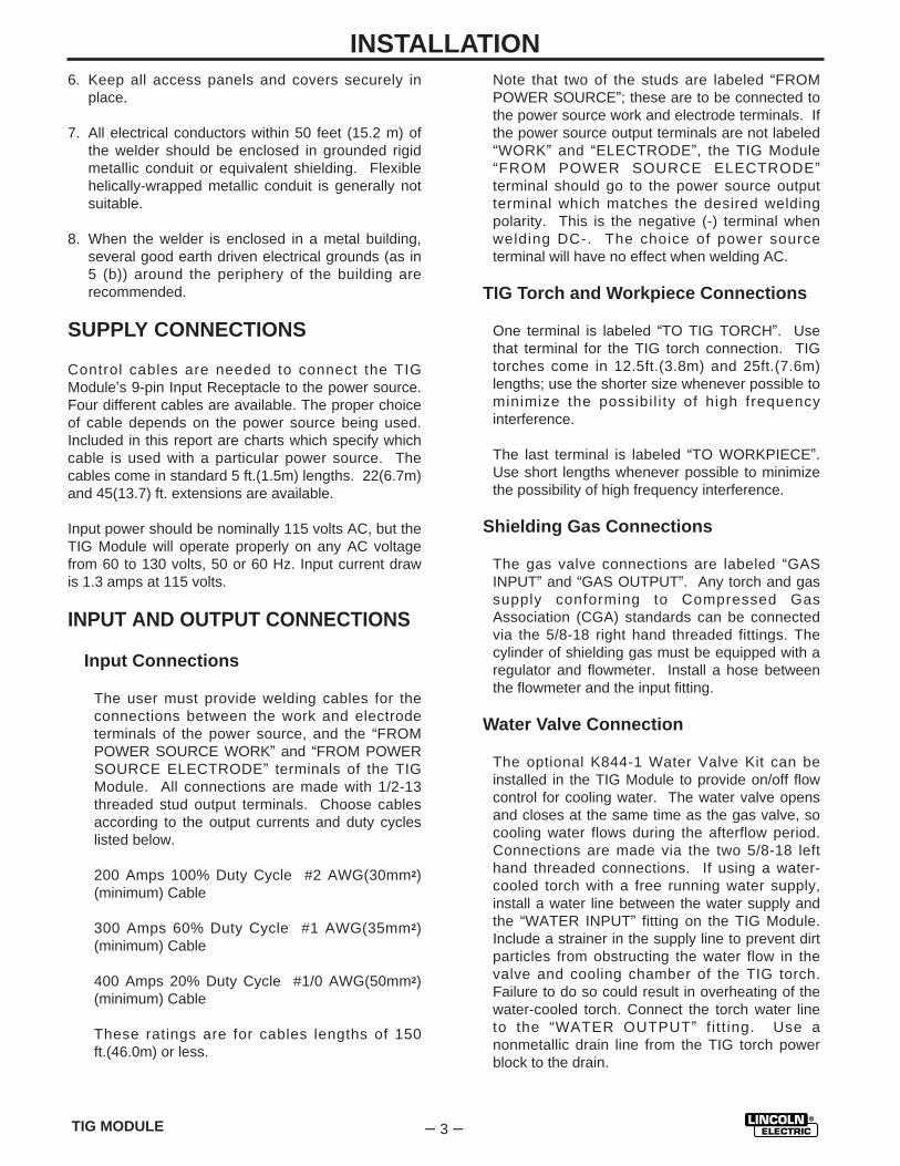
The user must provide welding cables for theconnections between the work and electrodeterminals of the power source, and the “FROMPOWER SOURCE WORK” and “FROM POWERSOURCE ELECTRODE” terminals of the TIGModule. All connections are made with 1/2-13threaded stud output terminals. Choose cablesaccording to the output currents and duty cycleslisted below.
200 Amps 100% Duty Cycle #2 AWG(30mm2)(minimum) Cable
300 Amps 60% Duty Cycle #1 AWG(35mm2)(minimum) Cable
400 Amps 20% Duty Cycle #1/0 AWG(50mm2)(minimum) Cable
These ratings are for cables lengths of 150ft.(46.0m) or less.
Note that two of the studs are labeled “FROMPOWER SOURCE”; these are to be connected tothe power source work and electrode terminals. Ifthe power source output terminals are not labeled“WORK” and “ELECTRODE”, the TIG Module“FROM POWER SOURCE ELECTRODE”terminal should go to the power source outputterminal which matches the desired weldingpolarity. This is the negative (-) terminal whenwelding DC-. The choice of power sourceterminal will have no effect when welding AC.
TIG Torch and Workpiece Connections
One terminal is labeled “TO TIG TORCH”. Usethat terminal for the TIG torch connection. TIGtorches come in 12.5ft.(3.8m) and 25ft.(7.6m)lengths; use the shorter size whenever possible tominimize the possibil i ty of high frequencyinterference.
The last terminal is labeled “TO WORKPIECE”.Use short lengths whenever possible to minimizethe possibility of high frequency interference.
Shielding Gas Connections
The gas valve connections are labeled “GASINPUT” and “GAS OUTPUT”. Any torch and gassupply conforming to Compressed GasAssociation (CGA) standards can be connectedvia the 5/8-18 right hand threaded fittings. Thecylinder of shielding gas must be equipped with aregulator and flowmeter. Install a hose betweenthe flowmeter and the input fitting.
Water Valve Connection
The optional K844-1 Water Valve Kit can beinstalled in the TIG Module to provide on/off flowcontrol for cooling water. The water valve opensand closes at the same time as the gas valve, socooling water flows during the afterflow period.Connections are made via the two 5/8-18 lefthand threaded connections. If using a water-cooled torch with a free running water supply,install a water line between the water supply andthe “WATER INPUT” fitting on the TIG Module.Include a strainer in the supply line to prevent dirtparticles from obstructing the water flow in thevalve and cooling chamber of the TIG torch.Failure to do so could result in overheating of thewater-cooled torch. Connect the torch water lineto the “WATER OUTPUT” f i t t ing. Use anonmetallic drain line from the TIG torch powerblock to the drain.

– 4 –
INSTALLATION
TIG MODULE
If using a water cooled torch with a water cooler, do not install the water valve. It will block thewater f low, possibly damaging the pump.Magnum water coolers are an exception to thisrule. Refer to the manufacturer’s instructionsprovided with the cooler.
INSTALLATION OF FIELD INSTALLEDACCESSORIES
Installation of the K963 Hand Amptrol, K870 FootAmptrol, and K814 Arc Start Switch is as follows:
Connect the 6-pin MS-type circular connector tothe Remote Receptacle on the TIG Module.Secure with the threaded collar.
Installation of the K936-[ ] Input Cables and K937-[ ]Extension Cables is as follows:
Connect the 9-socket MS-type circular connectoron the Input Cable to the Input Receptacle on theTIG Module. Secure with the threaded collar. Ifone or more K937-[ ] Extension Cables are used,connect them between the TIG Module and theK936-[ ] Input cable.
Installation instructions for the K938-1 Contactor Kit,K844-1 Water Valve Kit and the K939-1 Docking Kitare included with those kits.

INSTALLATION WITH A POWER SOURCE
Ranger 8 Installation
Tables 1 and 2 list the required and optionalequipment for installing and operating the TIGModule with a Ranger 8. Table 1 is for theRanger 8, and table 2 is for the Ranger 8 with theK892-1 Remote Kit installed. The Remote Kitinstallation is identified by the presence of a 6-pinremote connector located between the outputstuds.
Refer to the Connection Diagrams Figures 1 and2. Figure 1 is for the Ranger 8, and figure 2, forthe Ranger 8 with the K892-1 Remote Kitinstalled. Make sure all connections are tightbefore proceeding.
INSTALLATION
– 5 –TIG MODULE
RANGER 8 (WITH NO K892-1 REMOTE KIT) AND THE TIG MODULEREQUIRED EQUIPMENT
ControlCable
ContactorKit
Work andElectrode
Leads fromRanger 8 toTIG Module
TIGTorch
WorkLead
Shielding Gas,Regulator,Flowmeter
Arc StartSwitch
K936-49-pin to
115V Plug
K938-1Field
Installed
User Supplied;Length as
Req’d. CableSized to Match
Current andDuty Cycle
UserSupplied
User Supplied;Length as
Req’d. CableSized to Match
Current andDuty Cycle
UserSupplied
K814
RANGER 8 (WITH NO K892-1 REMOTE KIT) AND THE TIG MODULEOPTIONAL EQUIPMENT
ControlCable
Extension
WaterValve
DockingKit
K937 - [ ]Extension
9-pin to 9-pin
K844-1 K939-1Mounts to
Ranger 8 Roof
TABLE 1

INSTALLATION
– 6 – TIG MODULE
FIG
UR
E1:
RA
NG
ER
8 /
TIG
MO
DU
LE
CO
NN
EC
TIO
N D
IAG
RA
M
5
10
152
0
25
30
35
40 4
5
50
55
S
CO
NT
INU
OU
S
OF
F
PO
WE
R
2
AFT
ER
FLO
W
MO
DE
LC
OD
ES
ER
IAL
NO
.
TH
E L
INC
OLN
ELE
CT
RIC
CO
.C
LE
VE
LA
ND
, O
HIO
U.S
.A.
INP
UT
PO
RT
AB
LE
HI-
FR
EQ
WA
RN
ING
OF
F
O
ON
L9440
1
HIG
H F
RE
QU
EN
CY
LO
CA
L
11
5 V
1
.3 A
5
0/6
0 H
z
LIN
CO
LN
R
EL
EC
TR
IC
0
1
2
3
45
6
7
8
9
10
CU
RR
EN
T
SW
ITC
H
TM
CU
RR
EN
T C
ON
TR
OL
RE
MO
TE
AM
PT
RO
L
HF
ST
AR
T O
NL
Y
20
%
35
0A
60
%1
00
%
25
0A
18
0A
RA
TE
D C
AP
AC
ITY
20
A T
O 3
50
A
WA
RN
ING
Do
no
t o
pe
rate
wit
h p
an
els
op
en
.
Dis
co
nn
ec
t N
EG
AT
IVE
(-)
BA
TT
ER
Y L
EA
D
be
fore
se
rvic
ing
.
Do
no
t to
uc
h e
lec
tric
ally liv
e p
art
s.
Ke
ep
gu
ard
s in
pla
ce
.
Ke
ep
aw
ay f
rom
mo
vin
g p
art
s.
On
ly q
ua
lifi
ed
pe
rso
nn
el sh
ou
ld in
sta
ll,u
se
or
se
rvic
e t
his
eq
uip
me
nt.
5
10
152
0
25
30
35
40 4
5
50
55
S
CO
NT
INU
OU
S
OF
F
2
MO
DE
LC
OD
ES
ER
IAL
NO
.
TH
E L
INC
OLN
ELE
CT
RIC
CO
.C
LE
VE
LA
ND
, O
HIO
U.S
.A.
INP
UT
PO
RT
AB
LE
HI-
FR
EQ
WA
RN
ING
OF
F
O
ON
L9440
1
LO
CA
L
11
5 V
1
.3 A
5
0/6
0 H
z
LIN
CO
LN
R
EL
EC
TR
IC
0
1
2
3
45
6
7
8
9
10
CO
NT
RO
L
TM
RE
MO
TE
AM
PT
RO
L
HF
ST
AR
T O
NL
Y
20
%
35
0A
60
%1
00
%
25
0A
18
0A
RA
TE
D C
AP
AC
ITY
20
A T
O 3
50
A
TO
GA
S
INP
UT
FIT
TIN
G
FL
OW
ME
TE
R
AR
GO
N G
AS
CY
LIN
DE
R
K8
14
AR
C S
TA
RT
SW
ITC
H
M17
530
12-1
-94
RE
GU
LA
TO
R
WE
LD
ING
CA
BL
ES
MU
ST
BE
PR
OP
ER
LY
SIZ
ED
FO
R T
HE
CU
RR
EN
T A
ND
DU
TY
CY
CL
E O
F A
PP
LIC
AT
ION
NO
TE
: T
his
dia
gra
m is
fo
r re
fere
nce
onl
y.
It w
as a
ccur
ate
at t
he t
ime
of
pri
ntin
g ,
how
ever
Lin
coln
Ele
ctri
c re
serv
es t
he r
ight
to
mak
e im
pro
vem
ents
and
mo
difi
catio
nsas
nec
essa
ry, i
f yo
u su
pec
t th
is in
form
atio
n to
be
inac
cura
te, w
rite
to
the
Ser
vice
Dep
artm
ent
for
a re
pla
cem
ent.
Giv
e th
e eq
uip
men
t co
de
num
ber
..

TIG MODULE – 7 –
INSTALLATION
RANGER 8 (WITH THE OPTIONAL K892-1 REMOTE KIT INSTALLED) AND THE TIG MODULEREQUIRED EQUIPMENT
ControlCable
ContactorKit
Work andElectrode
Leads fromRanger 8 toTIG Module
TIGTorch
WorkLead
Shielding Gas,Regulator,Flowmeter
Arc StartSwitch
K936-39-pin to
6-pinplus
115V Plug
K938-1Field
Installed
User Supplied;Length as
Req’d. CableSized to Match
Current andDuty Cycle
UserSupplied
User Supplied;Length as
Req’d. CableSized to Match
Current andDuty Cycle
UserSupplied
SeeOptional
EquipmentBelow
RANGER 8 (WITH THE OPTIONAL REMOTE KIT INSTALLED) AND THE TIG MODULEOPTIONAL EQUIPMENT
ControlCable
Extension
WaterValve
Arc StartSwitch
HandAmptrol
FootAmptrol
DockingKit
K937 - [ ]Extension
9-pin to 9-pin
K844-1 K814 K963 K870 K939-1 Mounts to
Ranger 8 Roof
TABLE 2

INSTALLATION
– 8 –
FIG
UR
E2:
RA
NG
ER
8 /
K89
2-1
RE
MO
TE
KIT
/ T
IG M
OD
UL
E C
ON
NE
CT
ION
DIA
GR
AM
5
10
152
0
25
30
35
40 4
5
50
55
S
CO
NT
INU
OU
S
OF
F
PO
WE
R
2
AFT
ER
FLO
W
MO
DE
LC
OD
ES
ER
IAL
NO
.
TH
E L
INC
OLN
ELE
CT
RIC
CO
.C
LE
VE
LA
ND
, O
HIO
U.S
.A.
INP
UT
PO
RT
AB
LE
HI-
FR
EQ
WA
RN
ING
OF
F
O
ON
L9440
1
HIG
H F
RE
QU
EN
CY
LO
CA
L
11
5 V
1
.3 A
5
0/6
0 H
z
LIN
CO
LN
R
EL
EC
TR
IC
0
1
2
3
45
6
7
8
9
10
CU
RR
EN
TC
ON
TR
OL
SW
ITC
H
TM
CU
RR
EN
T C
ON
TR
OL
RE
MO
TE
AM
PT
RO
L
HF
ST
AR
T O
NL
Y
20
%
35
0A
60
%1
00
%
25
0A
18
0A
RA
TE
D C
AP
AC
ITY
20
A T
O 3
50
A
WA
RN
ING
Do
no
t o
pe
rate
wit
h p
an
els
op
en
.
Dis
co
nn
ec
t N
EG
AT
IVE
(-)
BA
TT
ER
Y L
EA
D
be
fore
se
rvic
ing
.
Do
no
t to
uc
h e
lec
tric
ally liv
e p
art
s.
Ke
ep
gu
ard
s in
pla
ce
.
Ke
ep
aw
ay f
rom
mo
vin
g p
art
s.
On
ly q
ua
lifi
ed
pe
rso
nn
el sh
ou
ld in
sta
ll,u
se
or
se
rvic
e t
his
eq
uip
me
nt.
5
10
152
0
25
30
35
40 4
5
50
55
S
CO
NT
INU
OU
S
OF
F
PO
WE
R
2
AFT
ER
FLO
W
MO
DE
LC
OD
ES
ER
IAL
NO
.
TH
E L
INC
OLN
ELE
CT
RIC
CO
.C
LE
VE
LA
ND
, O
HIO
U.S
.A.
INP
UT
PO
RT
AB
LE
HI-
FR
EQ
WA
RN
ING
OF
F
O
ON
L9440
1
HIG
H F
RE
QU
EN
CY
LO
CA
L
11
5 V
1
.3 A
5
0/6
0 H
z
LIN
CO
LN
R
EL
EC
TR
IC
0
1
2
3
45
6
7
8
9
10
CU
RR
EN
TC
ON
TR
OL
SW
ITC
H
TM
CU
RR
EN
T C
ON
TR
OL
RE
MO
TE
AM
PT
RO
L
HF
ST
AR
T O
NL
Y
20
%
35
0A
60
%1
00
%
25
0A
18
0A
RA
TE
D C
AP
AC
ITY
20
A T
O 3
50
A
TO
GA
S
INP
UT
FIT
TIN
G
FL
OW
ME
TE
R
AR
GO
N G
AS
CY
LIN
DE
R
K8
70
FO
OT
AM
PT
RO
L
-OR
-
-OR
-
K9
63
HA
ND
AM
PT
RO
L
K8
14
AR
C S
TA
RT
SW
ITC
H
M17
531
4-19
-96D
RE
GU
LA
TO
R
WE
LD
ING
CA
BL
ES
MU
ST
BE
PR
OP
ER
LY
SIZ
ED
FO
R T
HE
CU
RR
EN
T A
ND
DU
TY
CY
CL
E O
F A
PP
LIC
AT
ION
NO
TE
: T
his
dia
gra
m is
fo
r re
fere
nce
onl
y.
It w
as a
ccur
ate
at t
he t
ime
of
pri
ntin
g ,
how
ever
Lin
coln
Ele
ctri
c re
serv
es t
he r
ight
to
mak
e im
pro
vem
ents
and
mo
difi
catio
nsas
nec
essa
ry, i
f yo
u su
pec
t th
is in
form
atio
n to
be
inac
cura
te, w
rite
to
the
Ser
vice
Dep
artm
ent
for
a re
pla
cem
ent.
Giv
e th
e eq
uip
men
t co
de
num
ber
..
TIG MODULE

TIG MODULE – 9 –
INSTALLATIONRanger 9 Installation
Table 3 lists the required and optional equipmentfor installing and operating the TIG Module with aRanger 9.
Refer to Figure 3 for the TIG Module/Ranger 9connection diagram. Make sure all connectionsare tight before proceeding.
RANGER 9 AND THE TIG MODULEREQUIRED EQUIPMENT
ControlCable
Work andElectrode
Leads fromRanger 9 toTIG Module
TIGTorch
WorkLead
Shielding Gas,Regulator,Flowmeter
Arc StartSwitch- OR -
Amptrol
K936-19-pin to 14-pin
User Supplied;Length as Req’d.Cable Sized toMatch Currentand Duty Cycle
UserSupplied
User Supplied;Length as Req’d.Cable Sized toMatch Currentand Duty Cycle
UserSupplied
SeeOptional
EquipmentBelow
RANGER 9 AND THE TIG MODULEOPTIONAL EQUIPMENT
Control CableExtension
WaterValve
Arc StartSwitch
HandAmptrol
FootAmptrol
DockingKit
K937 - [ ]Extension
9-pin to 9-pin
K844-1Field
Installed
K814 K963 K870 K939-1 Mounts to
Ranger 9 Roof
TABLE 3

INSTALLATION
– 10 –
FIG
UR
E3:
RA
NG
ER
9 /
TIG
MO
DU
LE
CO
NN
EC
TIO
N D
IAG
RA
M
5
10
152
0
25
30
35
40 4
5
50
55
S
CO
NT
INU
OU
S
OF
F
PO
WE
R
2
AFT
ER
FLO
W
MO
DE
LC
OD
ES
ER
IAL
NO
.
TH
E L
INC
OLN
ELE
CT
RIC
CO
.C
LE
VE
LA
ND
, O
HIO
U.S
.A.
INP
UT
PO
RT
AB
LE
HI-
FR
EQ
WA
RN
ING
OF
F
O
ON
L9440
1
HIG
H F
RE
QU
EN
CY
LO
CA
L
11
5 V
1
.3 A
5
0/6
0 H
z
LIN
CO
LN
R
EL
EC
TR
IC
0
1
2
3
45
6
7
8
9
10
CU
RR
EN
TC
ON
TR
OL
SW
ITC
H
TM
CU
RR
EN
T C
ON
TR
OL
RE
MO
TE
AM
PT
RO
L
HF
ST
AR
T O
NL
Y
20
%
35
0A
60
%1
00
%
25
0A
18
0A
RA
TE
D C
AP
AC
ITY
20
A T
O 3
50
A
WA
RN
ING
Do
no
t o
pe
rate
wit
h p
an
els
op
en
.
Dis
co
nn
ec
t N
EG
AT
IVE
(-)
BA
TT
ER
Y L
EA
D
be
fore
se
rvic
ing
.
Do
no
t to
uc
h e
lec
tric
ally liv
e p
art
s.
Ke
ep
gu
ard
s in
pla
ce
.
Ke
ep
aw
ay f
rom
mo
vin
g p
art
s.
On
ly q
ua
lifi
ed
pe
rso
nn
el sh
ou
ld in
sta
ll,u
se
or
se
rvic
e t
his
eq
uip
me
nt.
5
10
152
0
25
30
35
40 4
5
50
55
S
CO
NT
INU
OU
S
OF
F
PO
WE
R
2
AFT
ER
FLO
W
MO
DE
LC
OD
ES
ER
IAL
NO
.
TH
E L
INC
OLN
ELE
CT
RIC
CO
.C
LE
VE
LA
ND
, O
HIO
U.S
.A.
INP
UT
PO
RT
AB
LE
HI-
FR
EQ
WA
RN
ING
OF
F
O
ON
L9440
1
HIG
H F
RE
QU
EN
CY
LO
CA
L
11
5 V
1
.3 A
5
0/6
0 H
z
LIN
CO
LN
R
EL
EC
TR
IC
0
1
2
3
45
6
7
8
9
10
CU
RR
EN
TC
ON
TR
OL
SW
ITC
H
TM
CU
RR
EN
T C
ON
TR
OL
RE
MO
TE
AM
PT
RO
L
HF
ST
AR
T O
NL
Y
20
%
35
0A
60
%1
00
%
25
0A
18
0A
RA
TE
D C
AP
AC
ITY
20
A T
O 3
50
A
TO
GA
S
INP
UT
FIT
TIN
G
FL
OW
ME
TE
R
AR
GO
N G
AS
CY
LIN
DE
R
K8
70
FO
OT
AM
PT
RO
L
-OR
-
-OR
-
K9
63
HA
ND
AM
PT
RO
L
K8
14
AR
C S
TA
RT
SW
ITC
H
M
1753
2
4-19
-96D
RE
GU
LA
TO
R
WE
LD
ING
CA
BL
ES
MU
ST
BE
PR
OP
ER
LY
SIZ
ED
FO
R T
HE
CU
RR
EN
T A
ND
DU
TY
CY
CL
E O
F A
PP
LIC
AT
ION
NO
TE
: T
his
dia
gra
m is
fo
r re
fere
nce
onl
y.
It w
as a
ccur
ate
at t
he t
ime
of
pri
ntin
g ,
how
ever
Lin
coln
Ele
ctri
c re
serv
es t
he r
ight
to
mak
e im
pro
vem
ents
and
mo
difi
catio
nsas
nec
essa
ry, i
f yo
u su
pec
t th
is in
form
atio
n to
be
inac
cura
te, w
rite
to
the
Ser
vice
Dep
artm
ent
for
a re
pla
cem
ent.
Giv
e th
e eq
uip
men
t co
de
num
ber
..
TIG MODULE

TIG MODULE – 11 –
INSTALLATIONRanger 10 and Ranger 300 D Installation
Table 4 lists the required and optional equipmentfor installing and operating the TIG Module with aRanger 10 or Ranger 300 D.
Refer to Figure 4 for the TIG Module/Ranger 10connection diagram and to Figure 4A for the TIGModule/Ranger 300 D connection diagram. Makesure all connections are tight before proceeding.
TABLE 4
RANGER 10 / RANGER 300 D AND THE TIG MODULEREQUIRED EQUIPMENT
ControlCable
ContactorKit
Work andElectrode
Leads fromRanger 10 toTIG Module
TIGTorch
WorkLead
Shielding Gas,Regulator,Flowmeter
Arc StartSwitch- OR -
Amptrol
K936-39-pin to
6-pinplus
115V Plug
K938-1Field
Installed
User Supplied;Length as
Req’d. CableSized to Match
Current andDuty Cycle
UserSupplied
User Supplied;Length as
Req’d. CableSized to Match
Current andDuty Cycle
UserSupplied
SeeOptional
EquipmentBelow
RANGER 10 / RANGER 300 D AND THE TIG MODULEOPTIONAL EQUIPMENT
ControlCable
Extension
WaterValve
Arc StartSwitch
HandAmptrol
FootAmptrol
DockingKit
K937 - [ ]Extension
9-pin to 9-pin
K844-1 K814 K963 K870 K939-1 Mounts toRanger 10
Roof

INSTALLATION
– 12 –
FIG
UR
E4:
RA
NG
ER
10
/ TIG
MO
DU
LE
CO
NN
EC
TIO
N D
IAG
RA
M
5
10
152
0
25
30
35
40 4
5
50
55
S
CO
NT
INU
OU
S
OF
F
PO
WE
R
2
AFT
ER
FLO
W
MO
DE
LC
OD
ES
ER
IAL
NO
.
TH
E L
INC
OLN
ELE
CT
RIC
CO
.C
LE
VE
LA
ND
, O
HIO
U.S
.A.
INP
UT
PO
RT
AB
LE
HI-
FR
EQ
WA
RN
ING
OF
F
O
ON
L9440
1
HIG
H F
RE
QU
EN
CY
LO
CA
L
11
5 V
1
.3 A
5
0/6
0 H
z
LIN
CO
LN
R
EL
EC
TR
IC
0
1
2
3
45
6
7
8
9
10
CU
RR
EN
TC
ON
TR
OL
SW
ITC
H
TM
CU
RR
EN
T C
ON
TR
OL
RE
MO
TE
AM
PT
RO
L
HF
ST
AR
T O
NL
Y
20
%
35
0A
60
%1
00
%
25
0A
18
0A
RA
TE
D C
AP
AC
ITY
20
A T
O 3
50
A
WA
RN
ING
Do
no
t o
pe
rate
wit
h p
an
els
op
en
.
Dis
co
nn
ec
t N
EG
AT
IVE
(-)
BA
TT
ER
Y L
EA
D
be
fore
se
rvic
ing
.
Do
no
t to
uc
h e
lec
tric
ally liv
e p
art
s.
Ke
ep
gu
ard
s in
pla
ce
.
Ke
ep
aw
ay f
rom
mo
vin
g p
art
s.
On
ly q
ua
lifi
ed
pe
rso
nn
el sh
ou
ld in
sta
ll,u
se
or
se
rvic
e t
his
eq
uip
me
nt.
5
10
152
0
25
30
35
40 4
5
50
55
S
CO
NT
INU
OU
S
OF
F
PO
WE
R
2
AFT
ER
FLO
W
MO
DE
LC
OD
ES
ER
IAL
NO
.
TH
E L
INC
OLN
ELE
CT
RIC
CO
.C
LE
VE
LA
ND
, O
HIO
U.S
.A.
INP
UT
PO
RT
AB
LE
HI-
FR
EQ
WA
RN
ING
OF
F
O
ON
L9440
1
HIG
H F
RE
QU
EN
CY
LO
CA
L
11
5 V
1
.3 A
5
0/6
0 H
z
LIN
CO
LN
R
EL
EC
TR
IC
0
1
2
3
45
6
7
8
9
10
CU
RR
EN
TC
ON
TR
OL
SW
ITC
H
TM
CU
RR
EN
T C
ON
TR
OL
RE
MO
TE
AM
PT
RO
L
HF
ST
AR
T O
NL
Y
20
%
35
0A
60
%1
00
%
25
0A
18
0A
RA
TE
D C
AP
AC
ITY
20
A T
O 3
50
A
TO
GA
S
INP
UT
FIT
TIN
G
FL
OW
ME
TE
R
AR
GO
N G
AS
CY
LIN
DE
R
K8
70
FO
OT
AM
PT
RO
L
-OR
-
-OR
-
K9
63
HA
ND
AM
PT
RO
L
K8
14
AR
C S
TA
RT
SW
ITC
H
M17
533
11/9
6
RE
GU
LA
TO
R
EF
WE
LD
ING
CA
BL
ES
MU
ST
BE
PR
OP
ER
LY
S
IZE
D F
OR
TH
E C
UR
RE
NT
AN
D D
UT
YC
YC
LE
OF
AP
PL
ICA
TIO
N.
A T
12
24
6 B
YP
AS
S C
AP
AC
ITO
R A
SB
LY
. M
US
T B
E I
NS
TA
LL
ED
IN
TH
E R
AN
GE
R 1
0T
O P
RO
TE
CT
TH
E R
AN
GE
R 1
0 F
RO
MD
AM
AG
E.
NO
TE
: T
his
dia
gra
m is
fo
r re
fere
nce
onl
y.
It w
as a
ccur
ate
at t
he t
ime
of
pri
ntin
g ,
how
ever
Lin
coln
Ele
ctri
c re
serv
es t
he r
ight
to
mak
e im
pro
vem
ents
and
mo
difi
catio
nsas
nec
essa
ry, i
f yo
u su
pec
t th
is in
form
atio
n to
be
inac
cura
te, w
rite
to
the
Ser
vice
Dep
artm
ent
for
a re
pla
cem
ent.
Giv
e th
e eq
uip
men
t co
de
num
ber
..
TIG MODULE

INSTALLATION
– 12a –
FIG
UR
E4A
:
RA
NG
ER
300
D /
TIG
MO
DU
LE
CO
NN
EC
TIO
N D
IAG
RA
M
EL
EC
TR
OD
E
-OR
-
6 P
INA
MP
HE
NO
L
K8
14
AR
C S
TA
RT
SW
ITC
H
S237
32-1
0
K8
70
FO
OT
AM
PT
RO
L
-OR
-
K9
63
-1 H
AN
D A
MP
TR
OL
1/0
3
CA
UT
ION
:
AN
IN
CR
EA
SE
IN
TH
E T
HE
AC
AU
XIL
IAR
Y V
OL
TA
GE
. I
F T
HIS
VO
LT
AG
E G
OE
S O
VE
R 1
40
VO
LT
S,
WIR
E F
EE
DE
R C
ON
TR
OL
CIR
CU
ITS
MA
Y B
EA
NY
IN
CR
EA
SE
OF
TH
E H
IGH
ID
LE
EN
GIN
E R
PM
BY
CH
AN
GIN
G T
HE
GO
VE
RN
OR
SE
TT
ING
OR
OV
ER
RID
ING
TH
E T
HR
OT
TL
E L
INK
AG
E W
ILL
CA
US
E
TH
E E
NG
INE
WE
LD
ER
OP
ER
AT
ING
MA
NU
AL
.
AP
PL
ICA
TIO
NS
. S
EE
OP
ER
AT
ING
MA
NU
AL
.
N.C
. P
LA
CE
WE
LD
ER
TE
RM
INA
LS
SW
ITC
H T
O "
RE
MO
TE
LY
CO
NT
RO
LL
ED
" P
OS
ITIO
N.
N.A
. W
EL
DIN
G C
AB
LE
S M
US
T B
E O
F P
RO
PE
R C
AP
AC
ITY
FO
R T
HE
CU
RR
EN
T A
ND
DU
TY
CY
CL
E O
F I
MM
ED
IAT
E A
ND
FU
TU
RE
N.D
. P
LA
CE
OU
TP
UT
CO
NT
RO
L S
WIT
CH
IN
"R
EM
OT
E C
ON
TR
OL
" P
OS
ITIO
N.
DA
MA
GE
D.
TH
E E
NG
INE
GO
VE
RN
OR
SE
TT
ING
IS
PR
E-S
ET
AT
TH
E F
AC
TO
RY
- D
O N
OT
AD
JU
ST
AB
OV
E
RP
M S
PE
CIF
ICA
TIO
NS
LIS
TE
D I
N
N.E
.
PL
AC
E I
DL
ER
SW
ITC
H I
N "
HIG
H"
IDL
E P
OS
ITIO
N.
N.B
. U
SE
PO
LA
RIT
Y S
WIT
CH
TO
SE
LE
CT
DE
SIR
ED
EL
EC
TR
OD
E P
OL
AR
ITY
. P
OS
ITIO
N T
HE
RA
NG
E S
WIT
CH
TO
A "
ST
ICK
/WE
LD
" P
OS
ITIO
N.
FL
OW
ME
TE
R
K9
63
-3C
ON
TR
OL
CA
BL
E
Ke
ep
gu
ard
s in
pla
ce
.
Ke
ep
aw
ay f
rom
mo
vin
g p
art
s.
WA
RN
ING O
nly
qu
alifi
ed
pe
rso
nn
el sh
ou
ld in
sta
ll,u
se
or
se
rvic
e t
his
eq
uip
me
nt.
Do
no
t o
pe
rate
wit
h p
an
els
op
en
.
Dis
co
nn
ec
t N
EG
AT
IVE
(-)
BA
TT
ER
Y L
EA
D
be
fore
se
rvic
ing
.
INP
UT
RE
GU
LA
TO
R
TO
GA
S
FIT
TIN
G
Do
no
t to
uc
h e
lec
tric
ally liv
e p
art
s.
CY
LIN
DE
R
AR
GO
N G
AS
TO
WO
RK
[ ]
NO
TE
: T
his
dia
gra
m is
fo
r re
fere
nce
onl
y.
It w
as a
ccur
ate
at t
he t
ime
of
pri
ntin
g ,
how
ever
Lin
coln
Ele
ctri
c re
serv
es t
he r
ight
to
mak
e im
pro
vem
ents
and
mo
difi
catio
nsas
nec
essa
ry, i
f yo
u su
pec
t th
is in
form
atio
n to
be
inac
cura
te, w
rite
to
the
Ser
vice
Dep
artm
ent
for
a re
pla
cem
ent.
Giv
e th
e eq
uip
men
t co
de
num
ber
..
TIG MODULE

NOTES
– 12b – TIG MODULE

TIG MODULE – 13 –
INSTALLATION
TABLE 5
RANGER 10LX / RANGER 300D-LX AND THE TIG MODULEREQUIRED EQUIPMENT
ControlCable
ContactorKit
Work andElectrode
Leads fromRanger 10LX
toTIG Module
TIGTorch
WorkLead
Shielding Gas,Regulator,Flowmeter
Arc StartSwitch- OR -
Amptrol
K936-19-pin to14-pinPlug
K938-1Field
Installed
User Supplied;Length as
Req’d. CableSized to Match
Current andDuty Cycle
UserSupplied
User Supplied;Length as
Req’d. CableSized to Match
Current andDuty Cycle
UserSupplied
SeeOptional
EquipmentBelow
RANGER 10LX / RANGER 300D-LX AND THE TIG MODULEOPTIONAL EQUIPMENT
ControlCable
Extension
WaterValve
Arc StartSwitch
HandAmptrol
FootAmptrol
DockingKit
K937 - [ ]Extension
9-pin to 9-pin
K844-1 K814 K963 K870 K939-1 Mounts to
Ranger 10LXRoof
Ranger 10-LX and Ranger 300D-LX Installation
Table 5 lists the required and optional equipmentfor installing and operating the TIG Module with aRanger 10-LX or Ranger 300D-LX.
Refer to Figure 5 for the TIG Module/Ranger 10-LX connection diagram and Figure 5A for the TIGModule/Ranger 300D-LX connection diagram.Make sure all connections are t ight beforeproceeding.

INSTALLATION
– 14 –
FIG
UR
E5:
RA
NG
ER
10-
LX
/ T
IG M
OD
UL
E C
ON
NE
CT
ION
DIA
GR
AM
5
10
152
0
25
30
35
40 4
5
50
55
S
CO
NT
INU
OU
S
OF
F
PO
WE
R
2
AFT
ER
FLO
W
MO
DE
LC
OD
ES
ER
IAL
NO
.
TH
E L
INC
OLN
ELE
CT
RIC
CO
.C
LE
VE
LA
ND
, O
HIO
U.S
.A.
INP
UT
PO
RT
AB
LE
HI-
FR
EQ
WA
RN
ING
OF
F
O
ON
L9440
1
HIG
H F
RE
QU
EN
CY
LO
CA
L
11
5 V
1
.3 A
5
0/6
0 H
z
LIN
CO
LN
R
EL
EC
TR
IC
0
1
2
3
45
6
7
8
9
10
CU
RR
EN
TC
ON
TR
OL
SW
ITC
H
TM
CU
RR
EN
T C
ON
TR
OL
RE
MO
TE
AM
PT
RO
L
HF
ST
AR
T O
NL
Y
20
%
35
0A
60
%1
00
%
25
0A
18
0A
RA
TE
D C
AP
AC
ITY
20
A T
O 3
50
A
WA
RN
ING
Do
no
t o
pe
rate
wit
h p
an
els
op
en
.
Dis
co
nn
ec
t N
EG
AT
IVE
(-)
BA
TT
ER
Y L
EA
D
be
fore
se
rvic
ing
.
Do
no
t to
uc
h e
lec
tric
ally liv
e p
art
s.
Ke
ep
gu
ard
s in
pla
ce
.
Ke
ep
aw
ay f
rom
mo
vin
g p
art
s.
On
ly q
ua
lifi
ed
pe
rso
nn
el sh
ou
ld in
sta
ll,u
se
or
se
rvic
e t
his
eq
uip
me
nt.
5
10
152
0
25
30
35
40 4
5
50
55
S
CO
NT
INU
OU
S
OF
F
PO
WE
R
2
AFT
ER
FLO
W
MO
DE
LC
OD
ES
ER
IAL
NO
.
TH
E L
INC
OLN
ELE
CT
RIC
CO
.C
LE
VE
LA
ND
, O
HIO
U.S
.A.
INP
UT
PO
RT
AB
LE
HI-
FR
EQ
WA
RN
ING
OF
F
O
ON
L9440
1
HIG
H F
RE
QU
EN
CY
LO
CA
L
11
5 V
1
.3 A
5
0/6
0 H
z
LIN
CO
LN
R
EL
EC
TR
IC
0
1
2
3
45
6
7
8
9
10
CU
RR
EN
TC
ON
TR
OL
SW
ITC
H
TM
CU
RR
EN
T C
ON
TR
OL
RE
MO
TE
AM
PT
RO
L
HF
ST
AR
T O
NL
Y
20
%
35
0A
60
%1
00
%
25
0A
18
0A
RA
TE
D C
AP
AC
ITY
20
A T
O 3
50
A
TO
GA
S
INP
UT
FIT
TIN
G
FL
OW
ME
TE
R
AR
GO
N G
AS
CY
LIN
DE
R
K8
70
FO
OT
AM
PT
RO
L
-OR
-
-OR
-
K9
63
HA
ND
AM
PT
RO
L
K8
14
AR
C S
TA
RT
SW
ITC
H
M17
534
11/9
6
RE
GU
LA
TO
R
EF
WE
LD
ING
CA
BL
ES
MU
ST
BE
PR
OP
ER
LY
S
IZE
D F
OR
TH
E C
UR
RE
NT
AN
D D
UT
YC
YC
LE
OF
AP
PL
ICA
TIO
N.
A T
12
24
6 B
YP
AS
S C
AP
AC
ITO
R A
SB
LY
. M
US
T B
E I
NS
TA
LL
ED
IN
TH
E R
AN
GE
R 1
0T
O P
RO
TE
CT
TH
E R
AN
GE
R 1
0 F
RO
MD
AM
AG
E.
NO
TE
: T
his
dia
gra
m is
fo
r re
fere
nce
onl
y.
It w
as a
ccur
ate
at t
he t
ime
of
pri
ntin
g ,
how
ever
Lin
coln
Ele
ctri
c re
serv
es t
he r
ight
to
mak
e im
pro
vem
ents
and
mo
difi
catio
nsas
nec
essa
ry, i
f yo
u su
pec
t th
is in
form
atio
n to
be
inac
cura
te, w
rite
to
the
Ser
vice
Dep
artm
ent
for
a re
pla
cem
ent.
Giv
e th
e eq
uip
men
t co
de
num
ber
..
TIG MODULE

INSTALLATION
– 14a –
FIG
UR
E5A
:
RA
NG
ER
300
D-L
X /
TIG
MO
DU
LE
CO
NN
EC
TIO
N D
IAG
RA
M
14
PIN
AM
PH
EN
OL
EL
EC
TR
OD
E
K9
63
-1 H
AN
D A
MP
TR
OL
-OR
-
S237
32-9
K8
14
AR
C S
TA
RT
SW
ITC
H
K8
70
FO
OT
AM
PT
RO
L
-OR
-
B-UF
CA
UT
ION
:
AN
IN
CR
EA
SE
IN
TH
E T
HE
AC
AU
XIL
IAR
Y V
OL
TA
GE
. I
F T
HIS
VO
LT
AG
E G
OE
S O
VE
R 1
40
VO
LT
S,
WIR
E F
EE
DE
R C
ON
TR
OL
CIR
CU
ITS
MA
Y B
EA
NY
IN
CR
EA
SE
OF
TH
E H
IGH
ID
LE
EN
GIN
E R
PM
BY
CH
AN
GIN
G T
HE
GO
VE
RN
OR
SE
TT
ING
OR
OV
ER
RID
ING
TH
E T
HR
OT
TL
E L
INK
AG
E W
ILL
CA
US
E
TH
E E
NG
INE
WE
LD
ER
OP
ER
AT
ING
MA
NU
AL
.
AP
PL
ICA
TIO
NS
. S
EE
OP
ER
AT
ING
MA
NU
AL
.
N.C
. P
LA
CE
WE
LD
ER
TE
RM
INA
LS
SW
ITC
H T
O "
RE
MO
TE
LY
CO
NT
RO
LL
ED
" P
OS
ITIO
N.
N.A
. W
EL
DIN
G C
AB
LE
S M
US
T B
E O
F P
RO
PE
R C
AP
AC
ITY
FO
R T
HE
CU
RR
EN
T A
ND
DU
TY
CY
CL
E O
F I
MM
ED
IAT
E A
ND
FU
TU
RE
N.D
. P
LA
CE
OU
TP
UT
CO
NT
RO
L S
WIT
CH
IN
"R
EM
OT
E C
ON
TR
OL
" P
OS
ITIO
N.
DA
MA
GE
D.
TH
E E
NG
INE
GO
VE
RN
OR
SE
TT
ING
IS
PR
E-S
ET
AT
TH
E F
AC
TO
RY
- D
O N
OT
AD
JU
ST
AB
OV
E
RP
M S
PE
CIF
ICA
TIO
NS
LIS
TE
D I
N
N.E
.
PL
AC
E I
DL
ER
SW
ITC
H I
N "
HIG
H"
IDL
E P
OS
ITIO
N.
N.B
. U
SE
PO
LA
RIT
Y S
WIT
CH
TO
SE
LE
CT
DE
SIR
ED
EL
EC
TR
OD
E P
OL
AR
ITY
. P
OS
ITIO
N T
HE
RA
NG
E S
WIT
CH
TO
A "
ST
ICK
/WE
LD
" P
OS
ITIO
N.
FL
OW
ME
TE
R
K9
36
-1C
ON
TR
OL
CA
BL
E
Ke
ep
gu
ard
s in
pla
ce
.
Ke
ep
aw
ay f
rom
mo
vin
g p
art
s.
WA
RN
ING O
nly
qu
alifi
ed
pe
rso
nn
el sh
ou
ld in
sta
ll,u
se
or
se
rvic
e t
his
eq
uip
me
nt.
Do
no
t o
pe
rate
wit
h p
an
els
op
en
.
Dis
co
nn
ec
t N
EG
AT
IVE
(-)
BA
TT
ER
Y L
EA
D
be
fore
se
rvic
ing
.
INP
UT
RE
GU
LA
TO
R
TO
GA
S
FIT
TIN
G
Do
no
t to
uc
h e
lec
tric
ally liv
e p
art
s.
CY
LIN
DE
R
AR
GO
N G
AS
TO
WO
RK
[ ]
NO
TE
: T
his
dia
gra
m is
fo
r re
fere
nce
onl
y.
It w
as a
ccur
ate
at t
he t
ime
of
pri
ntin
g ,
how
ever
Lin
coln
Ele
ctri
c re
serv
es t
he r
ight
to
mak
e im
pro
vem
ents
and
mo
difi
catio
nsas
nec
essa
ry, i
f yo
u su
pec
t th
is in
form
atio
n to
be
inac
cura
te, w
rite
to
the
Ser
vice
Dep
artm
ent
for
a re
pla
cem
ent.
Giv
e th
e eq
uip
men
t co
de
num
ber
..
TIG MODULE

NOTES
– 14b– TIG MODULE

TIG MODULE – 15 –
INSTALLATIONInstallation with other Lincoln PowerSources
Installation consists of connecting the input workand electrode cables, TIG torch, work lead, theproper control cable, and an Arc Start Switch orAmptrol. Tables 6 and 7 list the equipmentrequired for installing and operating the TIGModule on various Lincoln power sources.
If the TIG Module is being used for AC TIGwelding, the TIG Module’s input power must beproperly phased with respect to the welder outputcurrent. This would be a front panel 115VACreceptacle for engine welders. For transformerwelders, the TIG Module must be connected tothe same phase as the welding supply. The bestway to assure this is to connect the TIG Moduleinput cord, properly fused, to a source of 115VACinside the power source. In Lincoln transformerwelders rated 250 amps and higher, this would be
the supply leads to the fan motor. Although theTIG Module will operate on a different phase, theAC TIG arc will be less stable.
For DC TIG welding, the TIG module’s input maybe connected to any convenient source of115VAC; the input phasing is unimportant.
Refer to Figure 6 for the connection diagram forthe TIG Module when used with various Lincolnpower sources. Make sure all connections aretight before proceeding.
If using the K936-2 Input Cable (9-socket to 8lugged leads), connect the leads at the powersource end of the cable to the matching terminalson the power source (2 to 2, 4 to 4, etc.).
For other installations, connect the plugs on theend of the Input Cable to the mating receptacleson the power source.
LINCOLN POWER SOURCES AND THE TIG MODULEREQUIRED EQUIPMENT TABLE
ControlCable
K936-3
K936-1
K936-4
K936-3
K936-4
PowerSources
R3R-AllDC-250DC-400DC-600
DC-650 PRO/DC-750G8000 (w/oK892
Remote Kit)G8000 (w/ K892
Remote Kit)Weldanpower 150
Weldanpower 150 AC/DCSA-250 PerkinsSAE-350 Deutz
Classic IIClassic III & IIID
Idealarc 250 AC/DC
ContactorKit
K938-1
------
K938-1
Work and ElectrodeLeads from PowerSource to the TIG
Module
User Supplied;Length as required
Cable sized tomatch current and
duty cycle
TIGTorch
UserSupplied
WorkLead
UserSupplied;Length asrequiredCable
sized tomatchcurrent
and dutycycle
ShieldingGas,
Regulator,Flowmeter
UserSupplied
Arc StartSwitch - or-
Amptrol
Amptrol*
Amptrol*
Arc StartSwitch
Amptrol*
Arc StartSwitch
* An Amptrol is recommended. If remote current control is not required, a K814 Arc Start Switch may be used.
TABLE 6

INSTALLATION
– 16 –
TABLE 7
LINCOLN POWER SOURCES AND THE TIG MODULEOPTIONAL EQUIPMENT TABLE
ControlCable
Extension
K937-[ ]
K937-[ ]*
K937- [ ]
K937-[ ]*
PowerSources
DC-250R3R-AllDC-400DC-600
DC-650 PRO/DC-750G8000 (w/oK892
Remote Kit)G8000 (w/ K892
Remote Kit)Weldanpower 150
Weldanpower 150 AC/DCSA-250 PerkinsSAE-350 Deutz
Classic IIClassic III & IIID
Idealarc 250 AC/DC
WaterValve
K844-1
Arc StartSwitch
K814
HandAmptrol
K963
----------
K963
----------
K870
----------
K870
----------
----------
K939-1
----------
FootAmptrol
DockingKit
* A standard 3-wire, grounding type extension cord (16 ga. minimum) may be used instead of the K937-[ ].
TIG MODULE

TIG MODULE – 17 –
INSTALLATIONF
IGU
RE
6:
TIG
MO
DU
LE
ON
A L
INC
OL
N P
OW
ER
SO
UR
CE
- C
ON
NE
CT
ION
DIA
GR
AM
5
10
152
0
25
30
35
40 4
5
50
55
S
CO
NT
INU
OU
S
OF
F
PO
WE
R
2
AFT
ER
FLO
W
MO
DE
LC
OD
ES
ER
IAL
NO
.
TH
E L
INC
OLN
ELE
CT
RIC
CO
.C
LE
VE
LA
ND
, O
HIO
U.S
.A.
INP
UT
PO
RT
AB
LE
HI-
FR
EQ
WA
RN
ING
OF
F
O
ON
L9440
1
HIG
H F
RE
QU
EN
CY
LO
CA
L
11
5 V
1
.3 A
5
0/6
0 H
z
LIN
CO
LN
R
EL
EC
TR
IC
0
1
2
3
45
6
7
8
9
10
CU
RR
EN
TC
ON
TR
OL
SW
ITC
H
TM
CU
RR
EN
T C
ON
TR
OL
RE
MO
TE
AM
PT
RO
L
HF
ST
AR
T O
NL
Y
20
%
35
0A
60
%1
00
%
25
0A
18
0A
RA
TE
D C
AP
AC
ITY
20
A T
O 3
50
A
WA
RN
ING
Do
no
t o
pe
rate
wit
h p
an
els
op
en
.
Do
no
t to
uc
h e
lec
tric
ally liv
e p
art
s.
Ke
ep
gu
ard
s in
pla
ce
.
Ke
ep
aw
ay f
rom
mo
vin
g p
art
s.
On
ly q
ua
lifi
ed
pe
rso
nn
el sh
ou
ld in
sta
ll,u
se
or
se
rvic
e t
his
eq
uip
me
nt.
5
10
152
0
25
30
35
40 4
5
50
55
S
CO
NT
INU
OU
S
OF
F
PO
WE
R
2
AFT
ER
FLO
W
MO
DE
LC
OD
ES
ER
IAL
NO
.
TH
E L
INC
OLN
ELE
CT
RIC
CO
.C
LE
VE
LA
ND
, O
HIO
U.S
.A.
INP
UT
PO
RT
AB
LE
HI-
FR
EQ
WA
RN
ING
OF
F
O
ON
L9440
1
HIG
H F
RE
QU
EN
CY
LO
CA
L
11
5 V
1
.3 A
5
0/6
0 H
z
LIN
CO
LN
R
EL
EC
TR
IC
0
1
2
3
45
6
7
8
9
10
CU
RR
EN
TC
ON
TR
OL
SW
ITC
H
TM
CU
RR
EN
T C
ON
TR
OL
RE
MO
TE
AM
PT
RO
L
HF
ST
AR
T O
NL
Y
20
%
35
0A
60
%1
00
%
25
0A
18
0A
RA
TE
D C
AP
AC
ITY
20
A T
O 3
50
A
TO
GA
S
INP
UT
FIT
TIN
G
FL
OW
ME
TE
R
AR
GO
N G
AS
CY
LIN
DE
R
K8
70
FO
OT
AM
PT
RO
L
-OR
-
-OR
-
K9
63
HA
ND
AM
PT
RO
L
K8
14
AR
C S
TA
RT
SW
ITC
H
RE
GU
LA
TO
R
K9
36
-[ ]
CO
NT
RO
L C
AB
LE
Dis
co
nn
ec
t N
EG
AT
IVE
(-)
BA
TT
ER
Y L
EA
D
or
inp
ut
po
we
r b
efo
re s
erv
icin
g.
TO
PO
WE
R S
OU
RC
E E
LE
CT
RO
DE
TE
RM
INA
L
TO
PO
WE
R S
OU
RC
E W
OR
K T
ER
MIN
AL
(IF
PR
ES
EN
T)
TO
6-P
IN O
R 1
4-P
IN M
S-C
ON
NE
CT
OR
M17
608
OR
TE
RM
INA
L S
TR
IP (
IF P
RE
SE
NT
)
WE
LD
ING
CA
BL
ES
MU
ST
BE
PR
OP
ER
LY
SIZ
ED
FO
R
TH
E C
UR
RE
NT
AN
D D
UT
Y C
YC
LE
OF
AP
PL
ICA
TIO
N
TO
GR
OU
ND
ED
11
5V
AC
SU
PP
LY
4-1
9-96
D
NO
TE
: T
his
dia
gra
m is
fo
r re
fere
nce
onl
y.
It w
as a
ccur
ate
at t
he t
ime
of
pri
ntin
g ,
how
ever
Lin
coln
Ele
ctri
c re
serv
es t
he r
ight
to
mak
e im
pro
vem
ents
and
mo
difi
catio
nsas
nec
essa
ry, i
f yo
u su
pec
t th
is in
form
atio
n to
be
inac
cura
te, w
rite
to
the
Ser
vice
Dep
artm
ent
for
a re
pla
cem
ent.
Giv
e th
e eq
uip
men
t co
de
num
ber
..

OPERATION
– 18 –
ELECTRIC SHOCKcan kill.
• Do not touch electrically live partsor electrode with skin or wetclothing.
• Insulate yourself from work andground.
• Always wear dry insulating gloves.
FUMES AND GASEScan be dangerous.
• Keep your head out of fumes.
• Use ventilation or exhaust toremove fumes from breathingzone.
WELDING SPARKScan cause fire orexplosion
• Keep flammable material away.
• Do not weld on containers thathave held combustibles.
ARC RAYScan burn.
• Wear eye, ear and bodyprotection.
OPERATING INSTRUCTIONS
General Warnings
SAFETY INSTRUCTIONS
Observe additional Safety Guidelines detailedthroughout this manual.
WARNING
TIG MODULE

TIG MODULE – 19 –
OPERATION
ON
OFF
INPUT
HIGH FREQUENCYCONTINUOUS
HIGH FREQUENCYSTART ONLY
AFTERFLOW
CURRENT CONTROL(OUTPUT)
LOCAL CURRENTCONTROL
REMOTE CURRENTCONTROL
GAS INPUT
GAS OUTPUT
WATER INPUT
WATER OUTPUT
INPUT
TIG TORCHCONNECTION
WORK CONNECTION
REMOTE CONTROLCONNECTION
INSTRUCTIONMANUAL
GRAPHIC SYMBOLS USED ON THIS EQUIPMENT OR IN THIS MANUAL
2
OPERATION
– 20 –
PRODUCT DESCRIPTION
The TIG Module is an accessory for constant currentpower sources. It provides high frequency andshielding gas control for AC and DC GTAW (TIG)welding applications, and easy connection of Amptrolremote controls to power sources having remotecontrol capability. It also provides contactor control ofthe welding current, always allowing the operator tomake and break the arc with an Arc Start Switch orAmptrol remote control. A contactor option must beused for power sources which do not have a built-incontactor in the constant current mode.
The K930-[ ] TIG Module is supplied withoutaccessories. Arc start switches, Amptrols, cables,torches and mounting brackets must be purchasedseparately.
RECOMMENDED PROCESSES ANDEQUIPMENT
Recommended for TIG welding with AC or AC/DCconstant current welding power sources rated 250amps or higher. This includes transformer,transformer/rectifier and engine driven power sourceswith constant current output. For a listing of machinesthat the TIG Module can be used with, see InstallationSection.
DESIGN SUMMARY
Operational Features and Controls
Wide input voltage range of 60 to 130 volts AC allowsoperation on Ranger power sources.
Power On/Off switch with Pilot Light.
High Frequency switch allows selection ofContinuous, Start Only, or Off.
Contactor control by an Arc Start Switch or Amptrol(optional Contactor Kit required with certain powersources).
Afterflow Timer allows adjustable cooling period forgas and water (optional) flow after the weld isstopped.
Current Control functions as an adjustable limitcontrol when using a remotely controllable powersource. Allows operator to adjust welding current atthe TIG module, instead of at the power source. Alsoallows Hand or Foot Amptrol control range to benarrowed, for better current control capability.
Fixed preflow timer for purging the weld area beforean arc is struck. Preflow timer is automaticallybypassed if a new weld is started during the Afterflowtime; this allows quick tacking or spot welding, withoutthe need to wait for the preflow time.
Design Features
Compact case is designed for easy carrying,complete with handle.
Case has rubber feet which provide cushioning andskid resistance when used as a portable unit.
Input studs, output studs, valve fittings and cablereceptacles are located under a protective door. Doorhas a stainless steel hinge to resist corrosion.
Modular construction makes for easy servicing. Allcontrol and timer functions are contained on oneprinted circuit board.
The case was designed to complement the Rangerpower source line, particularly the Ranger 8 andRanger 9.
High frequency bypass is built into the TIG Module.
No work sense lead is required (as it was on the K799Hi-Freq).
No power source matching switch is required.
Welding Capability
The TIG Module is designed for arc starting in manualGTAW (TIG) applications. Application to automatedGTAW equipment may be satisfactory also. It is theuser’s responsibility to investigate and resolve issuesregarding interfacing and operating with automatedGTAW equipment.
TIG MODULE

TIG MODULE – 21 –
OPERATION
OPERATION Users should familiarize themselves with Figure 7, Control Panel, before proceeding.
1 INPUT POWER SWITCH AND PILOT LIGHT -Turns the input power to the TIG Module on andoff. Red pilot light indicates that input power is“on”.
2 HIGH FREQUENCY SWITCH - Used to selectContinuous High Frequency, Start Only HighFrequency, or High Frequency Off.
3 AFTERFLOW CONTROL - Adjust the afterflowtime from 5 to 55 seconds. This is the time theshielding gas (and, if equipped, cooling water) flowsafter the weld is completed. This extra gas flowcools the TIG torch and the tungsten electrode.
4 CURRENT CONTROL - This control functions onlywhen the TIG module is used with a power sourcehaving remote control capability. It controls thewelding current, and is used in conjunction with theLocal/Remote Switch.
5 LOCAL/REMOTE SWITCH - This switch functionsonly when the TIG module is used with a powersource having remote control capability. When inthe Local position, all output current control is doneby the Current Control on the TIG Module. When inthe Remote position, the Current Control on theTIG Module sets the maximum available weldingcurrent, and an Amptrol, plugged into the AmptrolReceptacle, can adjust the welding current. Seethe Chart labeled “Use of the Current Control, ArcStart Switch and Amptrol on Ranger Welders withRemote Control.
LINCOLN R
ELECTRIC
V
HF HIGH FREQUENCY
2
LOCAL
WARNING
POWER AFTERFLOW
REMOTE
CURRENT CONTROL
I
O
OFF
ON
CONTINUOUS
OFF
HF
HF
O
START ONLY
A
1
2
3
4
5 6
7
8
9
105
10
15
20
2530
35
40
45
50
55 SECONDS
3 45
2
1
CONTROL PANEL
FIGURE 7

OPERATION
– 22 –
WARNING
ELECTRODE
WORK
V
1 2
34456
7
REAR CONNECTIONS
FIGURE 8
1 WARNING INFORMATION - Important informationregarding the safe installation, operation, andservicing of the TIG Module.
2 INPUT RECEPTACLE - For connecting theControl Cable from the power source. Thisreceptacle contains the following circuits: Inputpower, power source contactor control (whereapplicable) and power source remote control(where applicable). This is a 9-pin receptacle.
3 WATER VALVE FITTINGS (OPTIONAL) - Watervalve inlet and outlet fittings, 5/8-18 left-handthreads. For connection of cooling water to andfrom the TIG torch. Supplied as part of the optionalK844-1 Water Valve Kit.
4 POWER INPUT CONNECTIONS - Connections forthe work (bottom) and electrode (top) cables fromthe Ranger power source. 1/2-13 threaded studconnections.
5 POWER OUTPUT CONNECTIONS - Connectionsfor the work lead (bottom) and TIG torch (top). 1/2-13 threaded stud connections.
6 GAS VALVE FITTINGS - Gas valve inlet and outletfittings, 5/8-18 right hand threads. For connectionof the shielding gas supply and the TIG torch gasfitting.
7 ARC START SWITCH / AMPTROL RECEPTACLE -6-socket receptacle for connecting an arc startswitch or an Amptrol remote current control.
TIG MODULE

TIG MODULE – 23 –
OPERATIONRANGER 8 OPERATION
The tables (Table 8 & 9) list the recommended switchand control settings for the TIG Module/Ranger 8combination. The first table is for the Ranger 8, andthe second for the Ranger 8 with the K892-1 RemoteKit installed.
Operate the Ranger 8 in accordance with the Ranger8 Manual.
Note: For AC TIG welding, the maximum TIG weldingoutput currents on each range setting will beapproximately 50% higher that those markedon the nameplate. This is due to the specialnature of the AC TIG welding arc. Do not ACTIG weld on the 225AC range setting. Theoutput current may exceed the rating of theRanger 8.
K930-[ ] SETTINGS
TABLE 8: K930-[ ] / RANGER 8 (WITHOUT THE K892-1) SETTINGS
POWERHIGH
FREQUENCY AFTERFLOWCURRENTCONTROL
CURRENTCONTROLSWITCH
ON
START- OR -
CONTINUOUS
ADJUSTTO SUIT,
5 - 55 SECONDS
SETTING HASNO EFFECTON OUTPUT SETTING HAS
NO EFFECTON OUTPUT
2A
RANGER 8 (WITHOUT THE K892-1 REMOTE KIT) SETTINGS
IDLERSWITCH
STICK/TIGPOLARITY
RANGE CONTROL
HIGH
DC-
AC
SELECT TO SUIT,50 - 210
SELECT TO SUIT,50-175
SET FORDESIRED OUTPUT
CURRENT
HF

OPERATION
– 24 –
TABLE 9: K930-[ ] / RANGER 8 (WITH THE K892-1) SETTINGS
K930-[ ] SETTINGS
POWERHIGH
FREQUENCY AFTERFLOWCURRENTCONTROL
CURRENTCONTROLSWITCH
ON
START- OR -
CONTINUOUS
ADJUSTTO SUIT,
5 - 55 SECONDS
ADJUSTTO SUIT
0-10REMOTE (WITHAN AMPTROL)
LOCAL (WITH ANARC START
SWITCH)
2A
RANGER 8 (WITH THE K892-1 REMOTE KIT INSTALLED) SETTINGS
IDLERSWITCH
STICK/TIGPOLARITY
RANGECONTROL AT
WELDER / REMOTECONTROL
HIGH
DC-
AC
SELECT TO SUIT,50 - 210
SELECT TO SUIT,50-175 REMOTE CONTROL
If your Ranger 8 has the optional K892-1 RemoteReceptacle installed, refer to Figure 9, which coversthe proper use of the TIG Module Current Control, ArcStart Switch, and Amptrols.
Once the TIG Module and Ranger 8 are properly setup, TIG welding is very easy. Position the torch inplace, lower your helmet, and press the Arc StartSwitch or Amptrol. The power source contactor (orthe optional TIG Module contactor) will close, gas willflow for a one-half second preflow time, and the highfrequency will come on. The arc should strike and
welding should begin. At the end of the weld, simplyrelease the Arc Start Switch or Amptrol, and thecontactor will open, shutting off the arc. The Afterflowtime will begin, cooling the torch, protecting the weldand the tungsten.
If another weld is started during the Afterflow time,there will be no preflow time delay. The contactor willclose and the high frequency wil l come onimmediately when the Arc Start Switch or Amptrol ispressed.
HF
TIG MODULE

TIG MODULE – 25 –
OPERATION
AMPTROL POSITION HAS
NO EFFECT ON THE
OUTPUT CURRENT.
LIGHT PRESSURE -
LOW OUTPUT CURRENT
HEAVY PRESSURE -
LOCAL
REMOTE1
2
3
4
5 6
7
8
9
10
0
1
2
3
45
6
7
8
9
10
OUTPUT
HIGH
MED
LOW
4590
120
160
200
250
RANGE
RANGE SETTING.
OUTPUT CONTROL
AT WELDER
OUTPUT CONTROL
REMOTE
CHOOSE REMOTEOUTPUT CONTROL.
TIG MODULE SETTINGS
CURRENT CONTROLA
USE OF THE CURRENT LIMIT CONTROL,
CHOOSE THE
NO EFFECT ON THE OUTPUT.
A
B
AVAILABLE BECAUSE THE CURRENT CONTROL
IS SET TO THE HALF-WAY POINT.
FULL OUTPUT IS AVAILABLE BECAUSE
CONTROL SETS THE MAXIMUM AVAILABLE
WELDING CURRENT.
THE CURRENT CAN BE VARIED FROM
MINIMUM TO HALF OF THE RANGER SETTING
BECAUSE THE CURRENT CONTROL IS SET TO
THE HALF-WAY POINT.
THE CURRENT CAN BE VARIED FROMB
A
A
B
LOCAL
REMOTE1
2
3
4
5 6
7
8
9
10
CURRENT CONTROLA
A
BMINIMUM TO MAXIMUM OF THE RANGER
SETTING BECAUSE THE CURRENT CONTROL
KNOB IS SET TO MAXIMUM.
REMOTE CURRENT CONTROL. THE CURRENT
HALF THE RANGER SETTING IS
ARC. THE CURRENT CONTROL SETS THE
WELDING CURRENT.
EXAMPLE 1:OR AN AMPTROL IS USED TO START THE
AN ARC START SWITCH
AN AMPTROL IS USED FOREXAMPLE 2:
UP TO THE SETTING
OF THE CURRENT.
CONTROL.
THE CURRENT CONTROL IS SET TO MAXIMUM.
ARC START SWITCH, AND AMPTROL ON WELDERSEQUIPPED WITH REMOTE CONTROL CAPABILITY.
WELDER SETTINGS
(IF APPROPRIATE)THE OUTPUT DIAL HAS
FIGURE 9

OPERATION
– 26 –
RANGER 9 OPERATION
The table (Table 10) lists the recommended switchand control settings for the TIG Module/Ranger 9combination.
Operate the Ranger 9 in accordance with the Ranger9 Manual.
Note that for AC TIG welding, the maximum TIGwelding output currents on each range setting will beapproximately 50% higher that those marked on thenameplate. This is due to the special nature of theAC TIG welding arc. Do not AC TIG weld on the 200or 250 amp range settings. The output current mayexceed the rating of the Ranger 9.
Because your Ranger 9 has remote control capability,refer to Figure 9, which covers the proper use of the
TIG Module Current Control, Arc Start Switch, andAmptrols.Once the TIG Module and Ranger 9 are properly setup, TIG welding is very easy. Position the torch inplace, lower your helmet, and press the Arc StartSwitch or Amptrol. The Ranger 9’s output contactorwill close, the engine will go to high idle, gas will flow,and after a one-half second preflow time, the highfrequency will come on. The arc should strike andwelding should begin. At the end of the weld, simplyrelease the Arc Start Switch or Amptrol, and thecontactor will open, shutting off the arc. The Afterflowtime will begin, cooling the torch, protecting the weldand the tungsten.
If another weld is started during the Afterflow time,there will be no preflow time delay. The contactor willclose and the high frequency wil l come onimmediately when the Arc Start Switch or Amptrol ispressed.
TABLE 10: K930-[ ] / RANGER 9 SETTINGS
RANGER 9 SETTINGS
IDLERSWITCH
STICK/TIGPOLARITY RANGE
CONTROL ATWELDER / REMOTE
CONTROL
WELDING TERMINALSALWAYS
ON / REMOTELYCONTROLLED
AUTODC-
AC
SELECT TO SUIT,45 - 250
SELECT TO SUIT,45-160
REMOTECONTROL
REMOTELYCONTROLLED
K930-[ ] SETTINGS
POWERHIGH
FREQUENCY AFTERFLOWCURRENTCONTROL
CURRENTCONTROLSWITCH
ON
START- OR -
CONTINUOUS
ADJUSTTO SUIT,
5 - 55 SECONDS
ADJUSTTO SUIT
0-10REMOTE (WITHAN AMPTROL)
LOCAL (WITH ANARC START
SWITCH)
2AHF
TIG MODULE

TIG MODULE – 27 –
OPERATIONRANGER 10 / RANGER 300 D OPERATION
The table (Table 11) lists the recommended switch and control settingsfor the TIG Module/Ranger 10 or TIG Module/Ranger 300 Dcombination. Make sure all connections are tight before proceeding.
Operate the Ranger 10 or Ranger 300 D in accordance withthe proper Operator’s Manual.
Note that for AC TIG welding, the maximum TIG welding outputcurrents on each range setting will be approximately 50%higher that those marked on the nameplate. This is due to thespecial nature of the AC TIG welding arc. Do not AC TIG weldon the 200 or 250 amp range settings. The output current mayexceed the rating of the Ranger 10 or Ranger 300 D.
Because your Ranger 10 / Ranger 300 D has remote controlcapability, refer to the diagram Figure 9 which covers the
proper use of the Tig Module Current Control, Arc StartSwitches, and Amptrols.
Once the TIG Module and Ranger 10 or Ranger 300 D areproperly set up, TIG welding is very easy. Position the torchin place, lower your helmet, and press the Arc Start Switchor Amptrol. The TIG Module’s optional contactor will close,gas will flow for a one-half second preflow time, and the highfrequency will come on. The arc should strike and weldingshould begin. At the end of the weld, simply release the ArcStart Switch or Amptrol, and the contactor will open, shuttingoff the arc. The Afterflow time will begin, cooling the torch,protecting the weld and the tungsten.
If another weld is started during the Afterflow time, there willbe no preflow time delay. The contactor will close and thehigh frequency will come on immediately when the Arc StartSwitch or Amptrol is pressed.
TABLE 11: K930-[ ] / RANGER 10 or RANGER 300 D SETTINGSK930-[ ] SETTINGS
POWERHIGH
FREQUENCY AFTERFLOWCURRENTCONTROL
CURRENTCONTROLSWITCH
ON
START- OR -
CONTINUOUS
ADJUSTTO SUIT,
5 - 55 SECONDS
ADJUSTTO SUIT
0-10REMOTE (WITHAN AMPTROL)
LOCAL (WITH ANARC START
SWITCH)
2A
RANGER 10 SETTINGS
IDLERSWITCH
STICK/TIGPOLARITY
RANGE
OUTPUTCONTROLSWITCH
HIGH
DC-
AC
SELECT TO SUIT,45 - 250
SELECT TO SUIT,45-160
OUTPUTCONTROLREMOTE
HF

OPERATION
– 28 –
TABLE 12: K930-[ ] / RANGER 10-LX or RANGER 300 DLX SETTINGSK930-[ ] SETTINGS
POWERHIGH
FREQUENCY AFTERFLOWCURRENTCONTROL
CURRENTCONTROLSWITCH
ON
START- OR -
CONTINUOUS
ADJUSTTO SUIT,
5 - 55 SECONDS
ADJUSTTO SUIT
0-10REMOTE (WITHAN AMPTROL)
LOCAL (WITH ANARC START
SWITCH)
2A
RANGER 10-LX SETTINGS
IDLERSWITCH
STICK/TIGPOLARITY
RANGE
OUTPUTCONTROLSWITCH
HIGH
DC-
AC
SELECT TO SUIT,45 - 250
SELECT TO SUIT,45-160
OUTPUTCONTROLREMOTE
RANGER 10-LX / RANGER 300 DLX OPERATION
The table (Table 12) lists the recommended switch and control settingsfor the TIG Module/Ranger 10-LX or TIG Module/Ranger 300 DLXcombination. Make sure all connections are tight before proceeding.
Operate the Ranger 10-LX or Ranger 300 DLX inaccordance with the proper Operator’s Manual.
Note that for AC TIG welding, the maximum TIG welding output currentson each range setting will be approximately 50% higher that thosemarked on the nameplate. This is due to the special nature of the ACTIG welding arc. Do not AC TIG weld on the 200 or 250 amp rangesettings. The output current may exceed the rating of the Ranger 10-LXor Ranger 300 DLX.
Because your Ranger 10-LX or Ranger 300 DLX hasremote control capability, refer to the diagram Figure 9
which covers the proper use of the TIG Module CurrentControl, Arc Start Switches, and Amptrols.
Once the TIG Module and Ranger 10-LX or Ranger 300 DLXare properly set up, TIG welding is very easy. Position the torchin place, lower your helmet, and press the Arc Start Switch orAmptrol. The TIG Module’s optional contactor will close, gaswill flow for a one-half second preflow time, and the highfrequency will come on. The arc should strike and weldingshould begin. At the end of the weld, simply release the ArcStart Switch or Amptrol, and the contactor will open, shutting offthe arc. The Afterflow time will begin, cooling the torch,protecting the weld and the tungsten.
If another weld is started during the Afterflow time, there willbe no preflow time delay. The contactor will close and thehigh frequency will come on immediately when the Arc StartSwitch or Amptrol is pressed.
HF
TIG MODULE

TIG MODULE – 29 –
OPERATIONOPERATION ON OTHER LINCOLNPOWER SOURCES
The table (Table 13) lists the recommended switchand control settings for the TIG Module when usedwith various Lincoln power sources.
Operate the power source in accordance with itsManual.
Note that AC power sources must be deratedapproximately 50% when used for AC TIG welding.This is due to the special nature of the TIG weldingarc. Input currents will also be higher when AC TIGwelding. Be sure the power source is properly fusedto handle this situation.
If your power source has remote control capability,
refer to the second half of the diagram Figure 9 whichcovers the proper use of the TIG Module CurrentControl with Hand and Foot Amptrols.
Once the TIG Module and the power source areproperly set up, TIG welding is very easy. Positionthe torch in place, lower your helmet, and press theArc Start Switch or Amptrol. The power sourcecontactor (or the optional TIG Module contactor) willclose, gas will flow for a one-half second preflow time,and the high frequency will come on. The arc shouldstrike and welding should begin. At the end of theweld, simply release the Arc Start Switch or Amptrol,and the contactor will open, shutting off the arc. TheAfterflow time will begin, cooling the torch, protectingthe weld and the tungsten. If another weld is startedduring the Afterflow time, there will be no preflow timedelay. The contactor will close immediately when theArc Start Switch or Amptrol is pressed.
TABLE 13: K930-[ ] / LINCOLN POWER SOURCE SETTINGSK930-[ ] SETTINGS
POWERHIGH
FREQUENCY AFTERFLOWCURRENTCONTROL
CURRENTCONTROLSWITCH
ON
START- OR -
CONTINUOUS
ADJUSTTO SUIT,
5 - 55 SECONDS
ADJUSTTO SUIT
0-10REMOTE (WITHAN AMPTROL)
LOCAL (WITH ANARC START
SWITCH)
2A
LINCOLN POWER SOURCE SETTINGS
WELD MODEPOLARITY
OUTPUTCONTROL
CURRENTCONTROLSWITCH
CONSULT YOURPOWER SOURCEINSTRUCTION OR
CHOOSE CONSTANTCURRENT (STICK)OUTPUT, AC OR
DC AS REQUIRED
IF POWER SOURCE HAS REMOTECONTROL CAPABILITY, THIS
CONTROL WILL HAVE NO EFFECT
FOR OTHER POWER SOURCES,SET TO OUTPUT CURRENT
DESIRED
SET TO REMOTE IFTHIS SWITCH APPEARS
ON THE POWERSOURCE
OPERATOR’S MANUALFOR COMPLETEINFORMATION
HF

OPERATION
– 30 –
TIG WELDING INFORMATION
.010 (.25)0.020 (.50)0.040 (1.0)
1/16 (1.6)
3/32 (2.4)1/8 (3.2)
5/32 (4.0)3/16 (4.8)1/4 (6.4)
2-155-2015-80
70-150
150-250250-400
400-500500-750750-1000
(3)
(3)
(3)
10-20
15-3025-40
40-5555-8080-125
2-155-1510-60
50-100
100-160150-210
200-275250-350325-450
2-155-20
15-80
70-150
140-235225-325
300-400400-500500-630
2-1510-2020-30
30-80
60-130100-180
100-240190-300250-400
---5-20
20-60
60-120
100-180160-250
200-320290-390340-525
3-8 (2-4)5-10 (3-5)5-10 (3-5)
5-10 (3-5)
13-17 (6-8)15-23 (7-11)
21-25 (10-12)23-27 (11-13)28-32 (13-15)
3-8 (2-4)5-10 (3-5)5-10 (3-5)
9-13 (4-6)
11-15 (5-7)11-15 (5-7)
13-17 (6-8)18-22 (8-10)23-27(11-13)
#4, #5, #6
#5, #6
#6, #7, #8
#8, #10
1%, 2%ThoriatedTungsten
1%, 2%ThoriatedTungsten
PureTungsten
1%, 2%ThoriatedTungsten
ZirconiatedPure
Tungsten
1%, 2%ThoriatedTungsten
Zirconiated AluminumStainless
Steel
TungstenElectrodeDiameterin. (mm)
TIG TorchNozzle
Size (4), (5)
DCEN ( - ) DCEP ( + ) Unbalanced Wave Balanced Wave
AC Approximate ArgonGas Flow RateC.F.H. (1/min.)
(1) When used with argon gas. The current ranges shown must be reduced when using argon/helium or pure helium shielding gasses.(2) Tungsten electrodes are classified as follows by the American Welding Society (AWS):
Pure . . . . . . . . . . . . . . . EWP1% Thoriated . . . . . . . . EWTh-12% Thoriated . . . . . . . . EWTh-2Though not yet recognized by the AWS, Ceriated Tungsten is now widely accepted as a substitute for 2% Thoriated Tungsten in AC and DC applications.
(3) DCEP is not commonly used in these sizes.(4) TIG torch nozzle “sizes” are in multiples of 1/16ths of an inch:
#4 = 1/4 in. (6 mm)#5 = 5/16 in. (8 mm)#6 = 3/8 in. (10 mm)#7 = 7/16 in. (11 mm)#8 = 1/2 in. (12.5 mm)
#10 = 5/8 in. (16 mm)(5) TIG torch nozzles are typically made from alumina ceramic. Special applications may require lava nozzles, which are less prone to breakage, but cannot
withstand high temperatures and high duty cycles.
TABLE 14TYPICAL CURRENT RANGES
(1)FOR TUNGSTEN ELECTRODES
(2)
TIG MODULE

TIG MODULE – 31 –
ACCESSORIESOPTIONS / ACCESSORIESThe following field installed Kits and accessories maybe used dependingon the application:
K936 Control Cables
At least one of the following control cables isneeded to connect the TIG Module to the powersource. Four different cables are available. Theproper choice of cable depends on the powersource being used. See the installation section tochoose the proper control cable. The controlcable carries one or more of the following circuitsbetween the TIG Module and the power source:Input power, remote control signals, contactorcontrol signals, and ground.
K936-1 9-Socket (at the TIG Module) to 14-pin(at the power source) (Contains circuits2, 4, 31, 32, 75, 76, 77 and ground)
K936-3 9-Socket to a grounded 115V plug and a6-pin MS-connector (Contains circuits31, 32, 75, 76, 77 and ground)
K936-4 9-Socket to a grounded 115V plug(Contains circuits 31, 32 and ground.)
K937 Control Cables Extensions
Control cable extensions are available in 22 and45 foot engths. These allow the TIG Module to beoperated at distances up to 200 feet from thepower source. The extensions connect betweenthe standard control cable and the TIG Module.
K937-22 22 foot extension cable, 9-Socket to 9-pin
K937-45 45 foot extension cable, 9-Socket to 9-pin
K938-1 Contactor Kit
This field installed kit must be installed in the TIGModule whenever it is used with a power sourcewhich does not have a built-in contactor for constantcurrent (stick/TIG) welding. See the list of compatiblepower sources to see which applications require theContactor Kit.
K939-1 Docking Kit
The Docking Kit provides a means to “dock” the TIGModule on top of a flat-roofed power source, or anyother flat surface measuring at least 10 X 15 inches(255 X 381 mm). It includes a latch and provisions fora user-supplied padlock to lock the TIG Module inplace.
K844-1 Water Valve Kit
A field installed kit which contains one water valve formounting inside the TIG Module. The water valve iscontrolled by the same preflow and afterflow timers asthe gas valve.
Other Compatible Lincoln Accessories:
K963 Hand AmptrolK870 Foot AmptrolK814 Arc Start SwitchAll Magnum TIG torches and accessories
Compatible Equipment
The TIG Module can be used with the followingLincoln power sources:
Ranger 81
Ranger 9Ranger 101
Ranger 10-LX1
DC-250DC-400DC-600DC-650Pro/DC-750R3R-300/400/500,including “I” versions1
Idealarc 250 AC/DC1
Weldanpower 1501
Weldanpower 150 AC/DC1
Weldanpower G80001
SA 250 Perkins1
SAE 350 Deutz1
SAE 4001
Classic I1,2
Classic II1
Classic III & IIID1
1Requires the K938-1 Contactor Kit in the TIG Module2Requires a source of 115VAC power
For installation of field installed accessories see theINSTALLATION SECTION.

SAFETY PRECAUTIONS
PERIODIC MAINTENANCE
Very little maintenance is required to keep your TIGModule in top operating condition. No specificschedule can be set for performing the followingitems; factors such as hours of usage and themachine environment should be considered whenestablishing a maintenance schedule.
1. Periodically blow off dust and dirt which mayaccumulate on the outside of the TIG Module.
2. Inspect the welding and control cables for fraying,cuts and bare spots.
3. Inspect the spark gap at regular intervals tomaintain the recommended spark gap setting.Use the following procedure:
The spark gap is set at the factory for a gap of0.015(.38mm) inches. This setting is proper formost applications.
To adjust the spark, first be sure that the Rangerwelder is off, and that the input cable isdisconnected from the Input Receptacle on theback of the TIG Module. Remove the outer casewraparound, and find the spark gap assemblylocated at the top right hand side of the internalcompartment. Check the spark gap setting with afeeler gauge. If adjustment is required, loosenone of the Allen head screws which secure thespark gap electrodes in place. Set the gap, andtighten the screw. Reinstall the case wraparound.
4. If the TIG Module is used in locations where there are large amounts of conductive metal or saltparticles in the air, it is recommended that theinside rear assembly of the TIG Module becleaned out with clean, dry, low pressurecompressed air on a regular basis (monthly, forexample). To do so, first be sure that the inputpower has been removed from the TIG Module.Remove the case wraparound. This exposes thespark gap, high voltage transformer, highfrequency transformer, and other components.Clean this area with compressed air.
MAINTENANCE
– 32 –
ELECTRIC SHOCK can kill.
• Only qualified personnel shouldperform this maintenance.
• Turn the input power OFF at thedisconnect switch or fuse boxbefore working on thisequipment.
• Do not touch electrically hot parts.
To avoid receiving a high frequency shock, keep theTIG torch and cables in good condition.
WARNING
WARNING
TIG MODULE

TIG MODULE
How To Use Troubleshooting Guide
This Troubleshooting Guide is designed to be used by the machine Owner/Operator. Unauthorized repairsperformed on this equipment may result in danger to the technician and machine operator and will invalidate yourfactory warranty. For your safety, please observe all safety notes and precautions detailed in the Safety Section ofthis manual to avoid electrical shock or danger while troubleshooting this equipment.___________________________________________________________________________________________
This Troubleshooting Guide is provided to help youlocate and correct possible machine misadjustments.Simply follow the three-step procedure listed below.
Step 1. LOCATE PROBLEM (SYMPTOM)Look under the column labeled “PROBLEM(SYMPTOMS)”. This column describes possiblesymptoms that your machine may exhibit. Find thelisting that best describes the symptom that yourmachine is exhibiting.
Step 2. PERFORM EXTERNAL RECOMMENDED TESTS
The second column labeled “POSSIBLE AREAS OFMISADJUSTMENT(S)” lists the obvious externalpossibilities that may contribute to the machinesymptom. Perform these tests/checks in the orderlisted. In general, these tests can be conductedwithout removing the case wrap-around cover.
Step 3. CONSULT LOCAL AUTHORIZED FIELD SERVICE FACILITY
If you have exhausted all of the recommended tests instep 2, consult your local Authorized Field ServiceFacility.
If for any reason you do not understand the test procedures or are unable to perform the tests/repairs safely,contact your local Authorized Field Service Facility for technical troubleshooting assistance before you proceed.
CAUTION
WARNING
– 33 –
TROUBLESHOOTING

TROUBLESHOOTING
– 34 –
Troubleshooting Guide Observe Safety Guidelinesdetailed in the beginning of this manual.
PROBLEMS(SYMPTOMS)
Major Physical or ElectricalDamage is Evident.
High frequency “jumps” from theelectrode to work but welding arcdoes not establish
POSSIBLECAUSE
1. Contact your local LincolnAuthorized Field ServiceFacility
1. Make certain that the welderpower source has weld output-Check for open circuit voltageat welding power source
2. Make certain that the tungstentype and size is correct for theprocess
3. The tungsten may becontaminated - clean or replace
RECOMMENDEDCOURSE OF ACTION
If all recommended possible areasof misadjustment have beenchecked and the problem persists,Contact your local LincolnAuthorized Field Service Facility.
OUTPUT PROBLEMS
If for any reason you do not understand the test procedures or are unable to perform the tests/repairs safely,contact your local Authorized Field Service Facility for technical troubleshooting assistance before you proceed.
CAUTION
TIG MODULE

TIG MODULE – 35 –
TROUBLESHOOTINGObserve Safety Guidelinesdetailed in the beginning of this manual.
Troubleshooting Guide
PROBLEMS(SYMPTOMS)
No weld output, no gas flow and nohigh frequency at spark gap
Low weld output current whenoperating in remote control
POSSIBLECAUSE
1. Check arc start switch orremote control unit
2. Make certain both the TIGModule and the welding powersource are powered up
1. Make certain the welder powersource is in the remote controlmode
2. The current control (R4) maybe set too low for the process
RECOMMENDEDCOURSE OF ACTION
If all recommended possible areasof misadjustment have beenchecked and the problem persists,Contact your local LincolnAuthorized Field Service Facility.
OUTPUT PROBLEMS
If for any reason you do not understand the test procedures or are unable to perform the tests/repairs safely,contact your local Authorized Field Service Facility for technical troubleshooting assistance before you proceed.
CAUTION

TROUBLESHOOTING
– 36 –
Troubleshooting Guide Observe Safety Guidelinesdetailed in the beginning of this manual.
PROBLEMS(SYMPTOMS)
High frequency not present orintermittent at torch electrode
High frequency not present at sparkgap
High Frequency stays on after thearc is established
POSSIBLECAUSE
1. Check for correct gas and gasflow
2. Check torch and work cablesfor breaks and leaks
3. Check spark gap for correctsetting 0.015in. (.25mm)
1. Make certain that the HighFrequency switch (S2) is NOTin the OFF position
2. Check spark gap for correctsetting 0.015in (.25mm)
1. High frequency switch (S2) is inthe continuous position
iRECOMMENDEDCOURSE OF ACTION
If all recommended possible areasof misadjustment have beenchecked and the problem persists,Contact your local LincolnAuthorized Field Service Facility.
HIGH FREQUENCY PROBLEMS
If for any reason you do not understand the test procedures or are unable to perform the tests/repairs safely,contact your local Authorized Field Service Facility for technical troubleshooting assistance before you proceed.
CAUTION
TIG MODULE

WIRING DIAGRAM
– 37 –TIG MODULE
TIG MODULE
232
231 2 4
J2
302
I
403
76
403
404
301
H
231
232
S1
CONTROL BOARD
OFF
ONLYSTART
404
75
206
+
205
210
CONTINUOUS
F
E
CURRENT SENSOR
G
77
G
311A
307
308
L9580
PROTECTIONBOARD
75
75A
76
209
LOCAL
208
CURRENT CONTROL
207
209
206
208
204
205
202
HIGH VOLTAGE TRANSFORMERT1OPTIONAL WATER SOLENOID VALVE
5EXAMPLE: THIS PIN IN
SV2
CONNECTOR J1 IS "4J1"
GAS SOLENOID VALVESV1CURRENT CONTROL SWITCHS5HIGH FREQUENCY SWITCHS2POWER SWITCH
B
C
D
SV2
POWER
OPTIONALWATERSOLENOIDVALVE
32
31
4
PL1
RECEPTACLE
R2
FROM POWER SOURCE
AFTERFLOW
CONTROL PANEL
S2
( TILTED DOWN AND VIEWED FROM BACK )
HIGH FREQUENCY
77
PILOT LIGHT
274A277A
1
CR1
BYPASS/STABILIZER
C1ELECTRICAL SYMBOLS PERR- REDN- BROWN RESISTOR: OHMS/WATTS
E1537U- BLUE
G- GREENCAPACITOR: MFD/VOLTS
W- WHITE
B- BLACKCOMPONENT VALUE UNITS:
LATCH
LEAD COLORING CODE:
CONNECTOR PIN NUMBERS:
6
WORK TERMINAL
10
HIGH FREQUENCY TRANSFORMERT2
L1
BOARD
314
315
L2
SPARKGAP
*
IF OPTIONAL CONTACTORIS CONNECTED
T2
TO TIG TORCH
311B
TO WORK
J3
PRI
*
*
*CR1
REMOTERECEPTACLE
ELECTRODE TERMINAL
HIGH VOLTAGE CAPACITOR .0025/10KV
J1
2
PILOT LIGHT
HI-FREQ. INDUCTOR
AFTERFLOW TIME POTENTIOMETER 500K/2WCURRENT CONTROL POTENTIOMETER 10K/2W
INPUT
A
CONTACTOR
J5
TM
BOARD
OPTIONALCONTACTOR
315 LUG =
314 LUG =
AND ARC START SWITCHOPTIONAL REMOTE AMPTROL
C1
OPTIONAL CONTACTOR
PL1
R4
L1,L2
R3
S1
BLEEDER RESISTOR 150/100WR2
CR1
FROM POWER SOURCE
4-19-96D
76A
275
75A
311B
311A
274
276
76A
277
77A
210
275
ELECTRODE TERMINAL
J4
T1
S
SEC
F
REARASSEMBLY
2J3 CONNECTS TO 2J5, ETC.NOTE: 1J3 CONNECTS TO 1J5,
A
B
C
D
E
FROM POWER SOURCE
20477A276277202
274
F
E
D
CB
A
J22
AT
MIN
IMU
M10
K A
-B
DEC
BA
J23
302301
REMOTE
S5
SV1
SWITCH
VALVEGAS SOLENOID
CURRENT CONTROL
3231
R4
ON
207
-
R3
R
206AOFF
WIRING DIAGRAM FOR CODES 10135, 10203 and 10284
NO
TE
: T
his
dia
gra
m is
fo
r re
fere
nce
onl
y.
It m
ay n
ot
be
accu
rate
fo
r al
l mac
hine
s co
vere
d b
y th
is m
anua
l. T
he s
pec
ific
dia
gra
m f
or
a p
artic
ular
co
de
is p
aste
d in
sid
eth
e m
achi
ne o
n o
ne o
f th
e en
clo
sure
pan
els.
If
the
dia
gra
m is
ille
gib
le, w
rite
to
the
Ser
vice
Dep
artm
ent
for
a re
pla
cem
ent.
Giv
e th
e eq
uip
men
t co
de
num
ber
.

WIRING DIAGRAM
– 38 –
TIG MODULE
232
231 2 4
J2
302
I
403
76
403
404
301
H
231
232
S1
CONTROL BOARD
OFF
ONLYSTART
404
75
206
+
205
210
CONTINUOUS
F
E
CURRENT SENSOR
G77
G
311A
307
308
L12065
PROTECTIONBOARD
75
75A
76
209
LOCAL
208
CURRENT CONTROL
207
209
206
208
204
205
202
HIGH VOLTAGE TRANSFORMERT1OPTIONAL WATER SOLENOID VALVE
5EXAMPLE: THIS PIN IN
SV2
CONNECTOR J1 IS "4J1"
GAS SOLENOID VALVESV1CURRENT CONTROL SWITCHS5HIGH FREQUENCY SWITCHS2POWER SWITCH
B
C
D
SV2
POWER
OPTIONALWATERSOLENOIDVALVE
32
31
4
PL1
RECEPTACLE
R2
FROM POWER SOURCE
AFTERFLOW
CONTROL PANEL
S2
( TILTED DOWN AND VIEWED FROM BACK )
HIGH FREQUENCY
77
PILOT LIGHT
274A277A
1
CR1
BYPASS/STABILIZER
C1ELECTRICAL SYMBOLS PERR- REDN- BROWN RESISTOR: OHMS/WATTS
E1537U- BLUE
G- GREENCAPACITOR: MFD/VOLTS
W- WHITE
B- BLACKCOMPONENT VALUE UNITS:
LATCH
LEAD COLORING CODE:
CONNECTOR PIN NUMBERS:
6
WORK TERMINAL
10
HIGH FREQUENCY TRANSFORMERT2
L1
BOARD
314
315
L2
SPARKGAP*
IF OPTIONAL CONTACTORIS CONNECTED
T2
TO TIG TORCH
311B
TO WORK
J3
PRI
*
**
CR1
REMOTERECEPTACLE
ELECTRODE TERMINAL
HIGH VOLTAGE CAPACITOR .0025/10KV
J1
WIRING DIAGRAM FOR CODE 11010
2
PILOT LIGHT
HI-FREQ. INDUCTOR
AFTERFLOW TIME POTENTIOMETER 500K/2WCURRENT CONTROL POTENTIOMETER 10K/2W
INPUT
A
CONTACTOR
J5
TM
BOARD
OPTIONALCONTACTOR
315 LUG =
314 LUG =
AND ARC START SWITCHOPTIONAL REMOTE AMPTROL
C1
OPTIONAL CONTACTOR
PL1
R4
L1,L2
R3
S1
BLEEDER RESISTOR 150/100WR2
CR1
FROM POWER SOURCE
A
76A
275
75A
311B
311A
274
276
76A
277
77A
210
275
ELECTRODE TERMINAL
J4
T1
S
SEC
F
REARASSEMBLY
2J3 CONNECTS TO 2J5, ETC.NOTE: 1J3 CONNECTS TO 1J5,
A
B
C
D
E
FROM POWER SOURCE
20477A276277202
274
F
E
D
CB
J22
AT
MIN
IMU
M10
K A
-B
DECBA
J23
302301
REMOTE
S5
SV1
SWITCH
VALVEGAS SOLENOID
CURRENT CONTROL
3231
R4
ON
207
-
R3
R206A
OFF
A
RESISTOR, BYPASS 15/100WR1
R1
NO
TE
: T
his
dia
gra
m is
fo
r re
fere
nce
onl
y.
It m
ay n
ot
be
accu
rate
fo
r al
l mac
hine
s co
vere
d b
y th
is m
anua
l. T
he s
pec
ific
dia
gra
m f
or
a p
artic
ular
co
de
is p
aste
d in
sid
eth
e m
achi
ne o
n o
ne o
f th
e en
clo
sure
pan
els.
If
the
dia
gra
m is
ille
gib
le, w
rite
to
the
Ser
vice
Dep
artm
ent
for
a re
pla
cem
ent.
Giv
e th
e eq
uip
men
t co
de
num
ber
.
TIG MODULE

NOTES

NOTES

– 52 –
WARNING
AVISO DEPRECAUCION
ATTENTION
WARNUNG
ATENÇÃO
Spanish
French
German
Portuguese
Japanese
Chinese
Korean
Arabic
READ AND UNDERSTAND THE MANUFACTURER’S INSTRUCTION FOR THIS EQUIPMENT AND THE CONSUMABLES TO BEUSED AND FOLLOW YOUR EMPLOYER’S SAFETY PRACTICES.
SE RECOMIENDA LEER Y ENTENDER LAS INSTRUCCIONES DEL FABRICANTE PARA EL USO DE ESTE EQUIPO Y LOSCONSUMIBLES QUE VA A UTILIZAR, SIGA LAS MEDIDAS DE SEGURIDAD DE SU SUPERVISOR.
LISEZ ET COMPRENEZ LES INSTRUCTIONS DU FABRICANT EN CE QUI REGARDE CET EQUIPMENT ET LES PRODUITS AETRE EMPLOYES ET SUIVEZ LES PROCEDURES DE SECURITE DE VOTRE EMPLOYEUR.
LESEN SIE UND BEFOLGEN SIE DIE BETRIEBSANLEITUNG DER ANLAGE UND DEN ELEKTRODENEINSATZ DESHERSTELLERS. DIE UNFALLVERHÜTUNGSVORSCHRIFTEN DES ARBEITGEBERS SIND EBENFALLS ZU BEACHTEN.
● Do not touch electrically live parts orelectrode with skin or wet clothing.
● Insulate yourself from work andground.
● No toque las partes o los electrodosbajo carga con la piel o ropamojada.
● Aislese del trabajo y de la tierra.
● Ne laissez ni la peau ni desvêtements mouillés entrer en contactavec des pièces sous tension.
● Isolez-vous du travail et de la terre.
● Berühren Sie keine stromführendenTeile oder Elektroden mit IhremKörper oder feuchter Kleidung!
● Isolieren Sie sich von denElektroden und dem Erdboden!
● Não toque partes elétricas eelectrodos com a pele ou roupamolhada.
● Isole-se da peça e terra.
● Keep flammable materials away.
● Mantenga el material combustiblefuera del área de trabajo.
● Gardez à l’écart de tout matérielinflammable.
● Entfernen Sie brennbarres Material!
● Mantenha inflamáveis bemguardados.
● Wear eye, ear and body protection.
● Protéjase los ojos, los oídos y elcuerpo.
● Protégez vos yeux, vos oreilles etvotre corps.
● Tragen Sie Augen-, Ohren- und Kör-perschutz!
● Use proteção para a vista, ouvido ecorpo.

– 53 –
WARNING
AVISO DEPRECAUCION
ATTENTION
WARNUNG
ATENÇÃO
Spanish
French
German
Portuguese
Japanese
Chinese
Korean
Arabic
LEIA E COMPREENDA AS INSTRUÇÕES DO FABRICANTE PARA ESTE EQUIPAMENTO E AS PARTES DE USO, E SIGA ASPRÁTICAS DE SEGURANÇA DO EMPREGADOR.
● Keep your head out of fumes.● Use ventilation or exhaust to
remove fumes from breathing zone.
● Los humos fuera de la zona derespiración.
● Mantenga la cabeza fuera de loshumos. Utilice ventilación oaspiración para gases.
● Gardez la tête à l’écart des fumées.● Utilisez un ventilateur ou un
aspirateur pour ôter les fumées deszones de travail.
● Vermeiden Sie das Einatmen vonSchweibrauch!
● Sorgen Sie für gute Be- undEntlüftung des Arbeitsplatzes!
● Mantenha seu rosto da fumaça.● Use ventilação e exhaustão para
remover fumo da zona respiratória.
● Turn power off before servicing.
● Desconectar el cable dealimentación de poder de lamáquina antes de iniciar cualquierservicio.
● Débranchez le courant avantl’entretien.
● Strom vor Wartungsarbeitenabschalten! (Netzstrom völligöffnen; Maschine anhalten!)
● Não opere com as tampas removidas.● Desligue a corrente antes de fazer
serviço.● Não toque as partes elétricas nuas.
● Do not operate with panel open orguards off.
● No operar con panel abierto oguardas quitadas.
● N’opérez pas avec les panneauxouverts ou avec les dispositifs deprotection enlevés.
● Anlage nie ohne Schutzgehäuseoder Innenschutzverkleidung inBetrieb setzen!
● Mantenha-se afastado das partesmoventes.
● Não opere com os paineis abertosou guardas removidas.

• Sales and Service through Subsidiaries and Distributors Worldwide •Cleveland, Ohio 44117-1199 U.S.A. TEL: 216.481.8100 FAX: 216.486.1751 WEB SITE: www.lincolnelectric.com
• World's Leader in Welding and Cutting Products •