Embed Size (px)
Citation preview
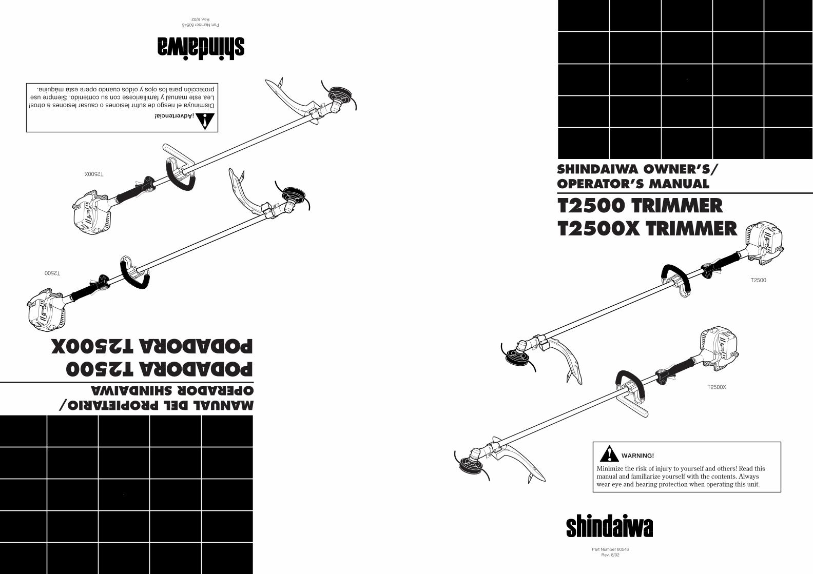
SHINDAIWA OWNER’S/OPERATOR’S MANUAL
T2500 TRIMMERT2500X TRIMMER
WARNING!
Minimize the risk of injury to yourself and others! Read thismanual and familiarize yourself with the contents. Alwayswear eye and hearing protection when operating this unit.
Part Number 80546Rev. 8/02
T2500
T2500X
MANUAL DEL PROPIETARIO/OPERADOR SHINDAIWA
PODADORA T2500PODADORA T2500X
¡Advertencia!
Disminuya el riesgo de sufrir lesiones o causar lesiones a otros!Lea este manual y familiaricese con su contenido. Siempre useprotección para los ojos y oídos cuando opere esta máquina.
Part Number 80546Rev. 8/02
T2500
T2500X
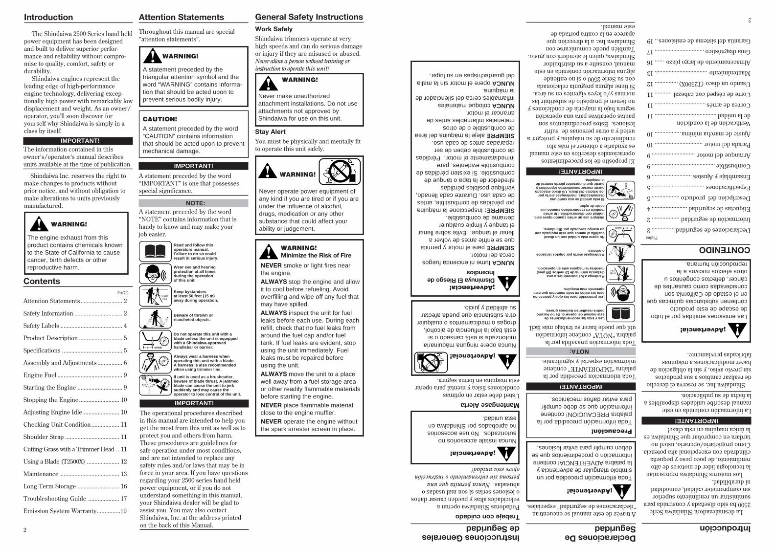
Throughout this manual are special“attention statements”.
IMPORTANT!
The operational procedures describedin this manual are intended to help youget the most from this unit as well as toprotect you and others from harm.These procedures are guidelines forsafe operation under most conditions,and are not intended to replace anysafety rules and/or laws that may be inforce in your area. If you have questionsregarding your 2500 series hand heldpower equipment, or if you do notunderstand something in this manual,your Shindaiwa dealer will be glad toassist you. You may also contactShindaiwa, Inc. at the address printedon the back of this Manual.
Attention StatementsIntroduction
PAGE
The Shindaiwa 2500 Series hand heldpower equipment has been designedand built to deliver superior perfor-mance and reliability without compro-mise to quality, comfort, safety ordurability.
Shindaiwa engines represent theleading edge of high-performanceengine technology, delivering excep-tionally high power with remarkably lowdisplacement and weight. As an owner/operator, you’ll soon discover foryourself why Shindaiwa is simply in aclass by itself!
Shindaiwa Inc. reserves the right tomake changes to products withoutprior notice, and without obligation tomake alterations to units previouslymanufactured.
Attention Statements ........................... 2
Safety Information ............................... 2
Safety Labels ........................................ 4
Product Description ............................ 5
Specifications ....................................... 5
Assembly and Adjustments ................ 6
Engine Fuel .......................................... 9
Starting the Engine ............................. 9
Stopping the Engine .......................... 10
Adjusting Engine Idle ....................... 10
Checking Unit Condition .................. 11
Shoulder Strap ................................... 11
Cutting Grass with a Trimmer Head .. 11
Using a Blade (T2500X) ..................... 12
Maintenance ...................................... 13
Long Term Storage ........................... 16
Troubleshooting Guide .................... 17
Emission System Warranty...............19
Contents
IMPORTANT!The information contained in thisowner's/operator's manual describesunits available at the time of publication.
CAUTION!A statement preceded by the word“CAUTION” contains informationthat should be acted upon to preventmechanical damage.
WARNING!
A statement preceded by thetriangular attention symbol and theword “WARNING” contains informa-tion that should be acted upon toprevent serious bodily injury.
Work SafelyShindaiwa trimmers operate at veryhigh speeds and can do serious damageor injury if they are misused or abused.Never allow a person without training orinstruction to operate this unit!
Stay AlertYou must be physically and mentally fitto operate this unit safely.
General Safety Instructions
WARNING!
WARNING!
Never operate power equipment ofany kind if you are tired or if you areunder the influence of alcohol,drugs, medication or any othersubstance that could affect yourability or judgement.
WARNING!Minimize the Risk of Fire
NEVER smoke or light fires nearthe engine.ALWAYS stop the engine and allowit to cool before refueling. Avoidoverfilling and wipe off any fuel thatmay have spilled.ALWAYS inspect the unit for fuelleaks before each use. During eachrefill, check that no fuel leaks fromaround the fuel cap and/or fueltank. If fuel leaks are evident, stopusing the unit immediately. Fuelleaks must be repaired beforeusing the unit.ALWAYS move the unit to a placewell away from a fuel storage areaor other readily flammable materialsbefore starting the engine.NEVER place flammable materialclose to the engine muffler.NEVER operate the engine withoutthe spark arrester screen in place.
Never make unauthorizedattachment installations. Do not useattachments not approved byShindaiwa for use on this unit.
WARNING!
The engine exhaust from thisproduct contains chemicals knownto the State of California to causecancer, birth defects or otherreproductive harm.
NOTE:A statement preceded by the word“NOTE” contains information that ishandy to know and may make yourjob easier.
IMPORTANT!
A statement preceded by the word“IMPORTANT” is one that possessesspecial significance.
Read and follow thisoperators manual.Failure to do so couldresult in serious injury.
Wear eye and hearingprotection at all timesduring the operation of this unit.
Keep bystandersat least 50 feet (15 m)away during operation.
Beware of thrown or ricocheted objects.
Do not operate this unit with a blade unless the unit is equipped with a Shindaiwa-approvedhandlebar or barrier.
Always wear a harness when operating this unit with a blade. A harness is also recommended when using trimmer line.
If unit is used as a brushcutter, beware of blade thrust. A jammedblade can cause the unit to jerk suddenly and may cause the operator to lose control of the unit.
2
A travéz de este manual se encuentran“declaraciones de seguridad” especiales.
IMPORTANTE!
El propósito de los procedimientosoperacionales descritos en este manuales ayudarle a obtener el más altorendimiento de su máquina y proteger austed y a otras personas de sufrirlesiones. Estos procedimientos sonpautas operativas para una operaciónsegura bajo la mayoría de condiciones yno tienen el propósito de substituir lasnormas y/o leyes vigentes en su área.Si tiene alguna pregunta relacionadacon su Serie 2500 o si no entiendealguna información contenida en estemanual, consulte a su distribuidorShindaiwa, quien le atenderá con gusto.También puede comunicarse conShindaiwa Inc. a la dirección queaparece en la contra portada deeste manual.
Declaraciones DeSeguridad Introducción
Página
La desmalezadora Shindaiwa Serie2500 ha sido diseñada y construida parasuministrar un rendimiento superiorsin comprometer calidad, comodidadni durabilidad.
Los motores Shindaiwa representanla tecnología líder de motores de altorendimiento, de poco peso y pequeñacilindrada con excepcional alta potencia.Como propietario/operario, usted notardara en comprobar que Shindaiwa esla única maquina en esta clase!
CONTENIDO
IMPORTANTE!
La información contenida en estemanual describe unidades disponibles ala fecha de su publicación.
Precaución!Toda información precedida por lapalabra PRECAUCION! contieneinformación que se debe cumplirpara evitar daños mecánicos.
¡Advertencia!
Toda información precedida por unsímbolo triangular de advertencia yla palabra ADVERTENCIA! contieneinformación o procedimientos que sedeben cumplir para evitar lesiones.
Trabaje con cuidadoPodadoras Shindaiwa operan avelocidades altas y pueden causar dañoso lesiones serias si son mal usadas oabusadas. Nunca permita que unapersona sin entrenamiento o instrucciónopere esta unidad!
Mantengase AlertaUsted debe estar en optimascondiciones física y mental para operaresta maquina en forma segura.
Instrucciones Generalesde Seguridad
¡Advertencia!
Nunca instale accesorios noautorizados. No use accesoriosno aprobados por Shindaiwa enesta unidad.
¡Advertencia!
Las emisiones emitidas por el tubode escape de este productocontienen substancias químicas queen el estado de California sonconsideradas como causantes decáncer, defectos congénitos uotros efectos nocivos a lareproducción humana.
NOTA:Toda información precedida por lapalabra “NOTA” contiene informaciónútil que puede hacer su trabajo más fácil.
IMPORTANTE!
Toda información precedida por lapalabra “IMPORTANTE” contieneinformación especial y significante.
Shindaiwa Inc. se reserva el derechode realizar cambios a sus productossin previo aviso, y sin la obligación dehacer modificaciones a máquinasfabricadas previamente.
Declaraciones de seguridad...............2
Información de seguridad..................2
Etiquetas de seguridad.......................4
Descripción del producto..................5
Especificaciones..................................5
Ensamblaje y Ajustes..........................6
Combustible.........................................9
Arranque del motor............................9
Parada del motor...............................10
Ajuste de marcha mínima.................10
Verificación de la condiciónde la unidad........................................11
Correa de arnés.................................11
Corte de césped con cabezal...........11
Usando un disco (T2500X)...............12
Mantenimiento..................................13
Almacenamiento de largo plazo......16
Guia diagnóstico................................17
Garantía del sistema de emisiones..19
¡Advertencia!
Nunca opere ninguna máquinariamotorizada si está cansado o siestá bajo la influencia de alcohol,drogas o medicamentos o cualquierotra substancia que pueda afectarsu abilidad y juicio.
¡Advertencia!Disminuya El Riesgo deIncendios
NUNCA fume ni encienda fuegoscerca del motor.SIEMPRE pare el motor y permitaque se enfrie antes de volver allenar el tanque. Evite sobre llenarel tanque y limpie cualquierderrame de combustible.SIEMPRE: Inspeccione la máquinapor pérdidas de combustible, antesde cada uso. Durante cada llenado,verifique posibles pérdidasalrededor de la tapa o tanque decombustible. Si existen pérdidas decombustible evidentes, pareinmediatamente el motor. Pérdidasde combustible deben de serreparadas antes de cada uso.SIEMPRE aleje la máquina del áreade combustible o de otrosmateriales inflamables antes dearrancar el motor.NUNCA coloque materialesinflamables cerca del silenciador dela máquina.NUNCA opere el motor sin la malladel guardachispas en su lugar.
2
Lea y siga las recomendaciones de este manual del operario. De no hacerlo podría resultar en lesiones graves.
Use protección para los ojos y protección para los oídos en todo momento que este operando esta maquina.
Mantenga a los transeúntes a una distancia mínima de 15 metros (50 pies) mientras la maquina este en operación.
Mantengase alerta por objetos lanzados o rebotes.
No opere esta unidad con un disco/ cuchilla al menos que este equipada con un mango aprobado por Shindaiwa.
Siempre use un arnés cuando opere esta unidad con disco/cuchilla. Un arnés también es recomendado cuando use cable de nylon.
Si esta unidad se usa como una desmalezadora, mantengase alerta por los rebotes del disco. Un disco atascado puede causar movimientos repentinos y puede que el operador pierda control de la maquina.
WARNING!Use Good Judgment
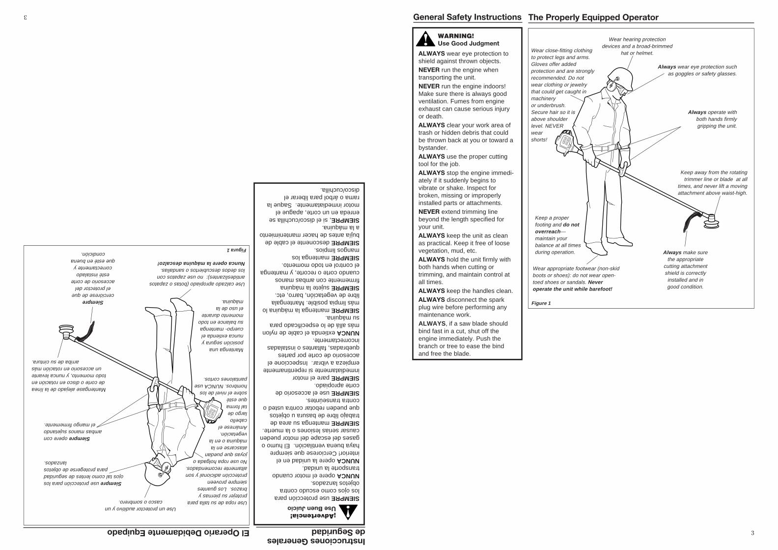
ALWAYS wear eye protection toshield against thrown objects.NEVER run the engine whentransporting the unit.NEVER run the engine indoors!Make sure there is always goodventilation. Fumes from engineexhaust can cause serious injuryor death.ALWAYS clear your work area oftrash or hidden debris that couldbe thrown back at you or toward abystander.ALWAYS use the proper cuttingtool for the job.ALWAYS stop the engine immedi-ately if it suddenly begins tovibrate or shake. Inspect forbroken, missing or improperlyinstalled parts or attachments.NEVER extend trimming linebeyond the length specified foryour unit.ALWAYS keep the unit as cleanas practical. Keep it free of loosevegetation, mud, etc.ALWAYS hold the unit firmly withboth hands when cutting ortrimming, and maintain control atall times.ALWAYS keep the handles clean.ALWAYS disconnect the sparkplug wire before performing anymaintenance work.ALWAYS, if a saw blade shouldbind fast in a cut, shut off theengine immediately. Push thebranch or tree to ease the bindand free the blade.
General Safety Instructions The Properly Equipped Operator
Always operate withboth hands firmlygripping the unit.
Wear close-fitting clothingto protect legs and arms.Gloves offer addedprotection and are stronglyrecommended. Do notwear clothing or jewelrythat could get caught inmachineryor underbrush.Secure hair so it isabove shoulderlevel. NEVERwearshorts!
Wear hearing protectiondevices and a broad-brimmed
hat or helmet.
Always wear eye protection suchas goggles or safety glasses.
Keep away from the rotatingtrimmer line or blade at all
times, and never lift a movingattachment above waist-high.
Wear appropriate footwear (non-skidboots or shoes): do not wear open-toed shoes or sandals. Neveroperate the unit while barefoot!
Keep a properfooting and do notoverreach—maintain yourbalance at all timesduring operation. Always make sure
the appropriatecutting attachmentshield is correctlyinstalled and ingood condition.
Figure 1
3
El Operario Debidamente Equipado
Siempre opere conambas manos sujetando
el mango firmemente.
Use ropa de su talla paraprotejer su piernas ybrazos. Los guantessiempre proveenprotección adicional y sonaltamente recomendados.No use ropa holgada ojoyas que puedanatascarse en lamáquina o en lavegetación.Amárrese elcabellolargo detal formaque estésobre el nivel de loshombros. NUNCA usepantalones cortos.
Use un protector auditivo y uncasco o sombrero.
Siempre use protección para losojos tal como lentes de seguridad
para protegerse de objetoslanzados.
Mantengase alejado de la líneade corte o disco en rotación entodo momento, y nunca levante
un accesorio en rotación másarriba de su cintura.
Use calzado apropiado (botas o zapatosantideslizantes): no use zapatos conlos dedos descubiertos o sandalias.Nunca opere la máquina descalzo!
Mantenga unaposición segura ynunca extienda elcuerpo- mantengasu balance en todomomento duranteel uso de lamáquina.Siempre
cerciórese de queel protector del
accesorio de corteesté instalado
correctamente yque esté en buena
condición.Figura 1
Instrucciones Generalesde Seguridad
¡Advertencia!Use Buen Juicio
SIEMPRE use protección paralos ojos como escudo contraobjetos lanzados.NUNCA opere el motor cuandotransporte la unidad.NUNCA opere la unidad en elinterior! Cerciorese que siemprehaya buena ventilación. El humo ogases del escape del motor puedencausar serias lesiones o la muerte.SIEMPRE mantenga su area detrabajo libre de basura u objetosque pueden rebotar contra usted ocontra transeúntes.SIEMPRE use el accesorio decorte apropiado.SIEMPRE pare el motorinmediatamente si repentinamenteempieza a vibrar. Inspeccione elaccesorio de corte por partesquebradas, faltantes o instaladasincorrectamente.NUNCA extienda el cable de nylonmás allá de lo especificado parasu máquina.SIEMPRE mantenga la máquina lomás limpia posible. Mantengalalibre de vegetación, barro, etc.SIEMPRE sujete la máquinafirmemente con ambas manoscuando corte o recorte, y mantengael control en todo momento.SIEMPRE mantenga losmangos limpios.SIEMPRE desconente el cable debujía antes de hacer mantenimientoa la máquina.SIEMPRE, si el disco/cuchilla seenreda en un corte, apague elmotor inmediatamente. Saque larama o árbol para liberar eldisco/cuchilla.
3
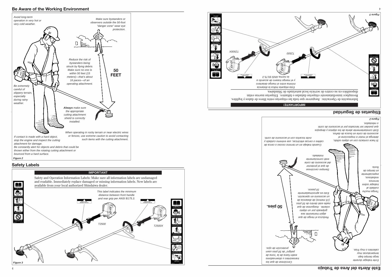
Safety Labels
Figure 3
IMPORTANT
Safety and Operation Information Labels: Make sure all information labels are undamagedand readable. Immediately replace damaged or missing information labels. New labels areavailable from your local authorized Shindaiwa dealer.
T2500
This label indicates the minimumdistance between front handleand rear grip per ANSI B175.3.
Be Aware of the Working Environment
Avoid long-termoperation in very hot orvery cold weather.
Make sure bystanders orobservers outside the 50-foot
“danger zone” wear eyeprotection.
Be extremelycareful ofslippery terrain,especiallyduring rainyweather.
Always make surethe appropriate
cutting attachmentshield is correctly
installed.
If contact is made with a hard object,stop the engine and inspect the cuttingattachment for damage.
When operating in rocky terrain or near electric wiresor fences, use extreme caution to avoid contacting
such items with the cutting attachment.
Be constantly alert for objects and debris that could bethrown either from the rotating cutting attachment orbounced from a hard surface.
Reduce the risk ofbystanders being
struck by flying debris.Make sure no one is
within 50 feet (15meters)—that’s about
16 paces—of anoperating attachment.
Figure 2
50FEET
T2500X
4
Etiquetas de Seguridad
Figura 3
IMPORTANTE!
Información de Operación: Asegurese que toda las etiquetas estén libres de daños y legibles.Reemplace inmediatamente etiquetas dañadas o faltantes. Etiquetas nuevas estándisponibles en su centro de servicio local autorizado de Shindaiwa.
T2500
Esta etiqueta indica la distanciamínima entre el mango delanteroy el mango trasero de acuerdo a
la norma ANSI B175.3
Esté Alerta del Area de Trabajo
Evite trabajar durantelargo tiempo bajotemperaturas muycalientes o muy frías.
Cerciórese de que lostranseúntes u observadores
estén fuera de la “zona depeligro” de 50 píes usen
protección de ojos.
Tenga muchocuidado altrabajar sobreterrenosresbalosos,especialmenteen tiempo delluvia.
Siempre cercióresede que el protector
del accesorio de corteesté correctamente
instalado.
Si hace contacto con un objeto sólido,detenga el motor e inspeccione elaccesorio de corte en busca de daños.
Cuando trabaje en un terreno rocoso o cerca decables o cercas eléctricas, use extremo cuidado y
evite tocarlos con el accesorio de corte.
Esté constantemente alerta de los objetos y despojosque puedan ser lanzados por el accesorio de corteo rebotados.
Reduzca el riesgo de quealgún transeúnte sea
golpeado por un objetovolante. Asegurese de quenadie esté dentro de 50 píes(15 metros) de distancia deun accesorio en operación.Esto es aproximadamente
16 pasos.
Figura 2
50 píes.
T2500X
4
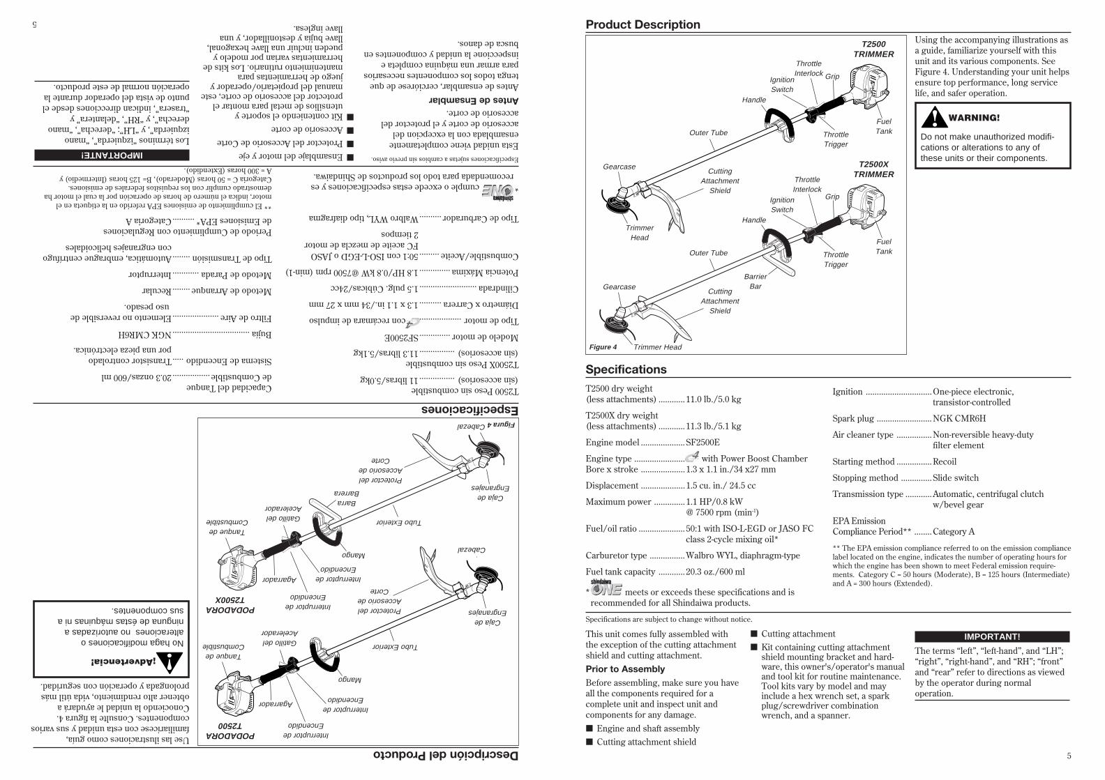
Product DescriptionUsing the accompanying illustrations asa guide, familiarize yourself with thisunit and its various components. SeeFigure 4. Understanding your unit helpsensure top performance, long servicelife, and safer operation.
Figure 4
Specifications
T2500 dry weight(less attachments) ............ 11.0 lb./5.0 kg
T2500X dry weight(less attachments) ............ 11.3 lb./5.1 kg
Engine model ....................SF2500E
Engine type ....................... with Power Boost ChamberBore x stroke .................... 1.3 x 1.1 in./34 x27 mm
Displacement .................... 1.5 cu. in./ 24.5 cc
Maximum power .............. 1.1 HP/0.8 kW@ 7500 rpm (min-1)
Fuel/oil ratio ..................... 50:1 with ISO-L-EGD or JASO FCclass 2-cycle mixing oil*
Carburetor type ................Walbro WYL, diaphragm-type
Fuel tank capacity ............ 20.3 oz./600 ml
Prior to AssemblyBefore assembling, make sure you haveall the components required for acomplete unit and inspect unit andcomponents for any damage.■ Engine and shaft assembly■ Cutting attachment shield
Specifications are subject to change without notice.
Ignition ..............................One-piece electronic,transistor-controlled
Spark plug .........................NGK CMR6H
Air cleaner type ................Non-reversible heavy-dutyfilter element
Starting method ................Recoil
Stopping method ..............Slide switch
Transmission type ............Automatic, centrifugal clutchw/bevel gear
EPA EmissionCompliance Period** ........Category A
** The EPA emission compliance referred to on the emission compliancelabel located on the engine, indicates the number of operating hours forwhich the engine has been shown to meet Federal emission require-ments. Category C = 50 hours (Moderate), B = 125 hours (Intermediate)and A = 300 hours (Extended).
IMPORTANT!
The terms “left”, “left-hand”, and “LH”;“right”, “right-hand”, and “RH”; “front”and “rear” refer to directions as viewedby the operator during normaloperation.
■ Cutting attachment■ Kit containing cutting attachment
shield mounting bracket and hard-ware, this owner's/operator's manualand tool kit for routine maintenance.Tool kits vary by model and mayinclude a hex wrench set, a sparkplug/screwdriver combinationwrench, and a spanner.
This unit comes fully assembled withthe exception of the cutting attachmentshield and cutting attachment.
* meets or exceeds these specifications and isrecommended for all Shindaiwa products.
WARNING!
Do not make unauthorized modifi-cations or alterations to any ofthese units or their components.
T2500XTRIMMER
Outer Tube
Trimmer Head
Grip
CuttingAttachment
Shield
Gearcase
Handle
ThrottleTrigger
ThrottleInterlock
IgnitionSwitch
FuelTank
BarrierBar
T2500TRIMMER
Outer Tube
TrimmerHead
Grip
CuttingAttachment
Shield
Gearcase
Handle
ThrottleTrigger
ThrottleInterlock
IgnitionSwitch
FuelTank
5
PODADORAT2500X
BarraBarrera
Tubo Exterior
Cabezal
Agarrador
Protector delAccesorio de
Corte
Caja deEngranajes
Mango
Gatillo delAcelerador
Interruptor deEncendido
Interruptor deEncendido
Tanque deCombustible
Descripción del ProductoUse las ilustraciones como guía,familiarícese con esta unidad y sus varioscomponentes. Consulte la figura 4.Conociendo la unidad le ayudará aobtener alto rendimiento, vida útil másprolongada y operación con seguridad.
Figura 4
Especificaciones
T2500 Peso sin combustible(sin accesorios)................11 libras/5.0kg
T2500X Peso sin combustible(sin accesorios)................11.3 libras/5.1kg
Modelo de motor..............SF2500E
Tipo de motor...................C4 con recámara de impulso
Diámetro x Carrera..........1.3 x 1.1 in./34 mm x 27 mm
Cilindrada..........................1.5 pulg. Cúbicas/24cc
Potencia Máxima..............1.8 HP/0.8 kW @7500 rpm (min-1)
Combustible/Aceite.........50:1 con ISO-L-EGD o JASOFC aceite de mezcla de motor2 tiempos
Tipo de Carburador..........Walbro WYL, tipo diafragma
Antes de EnsamblarAntes de ensamblar, cerciórese de quetenga todos los componentes necesariospara armar una máquina completa einspeccione la unidad y componentes enbusca de danos.
Especificaciones sujetas a cambios sin previo aviso.
Capacidad del Tanquede Combustible.................20.3 onzas/600 ml
Sistema de Encendido.....Transistor controladopor una pieza electrónica.
Bujía...................................NGK CMR6H
Filtro de Aire.....................Elemento no reversible de uso pesado.
Metodo de Arranque........Recular
Metodo de Parada............Interruptor
Tipo de Transmisión........Automática, embrague centrífugocon engranajes helicoidales
Periodo de Cumplimiento con Regulacionesde Emisiones EPA*..........Categoria A
** El cumplimiento de emisiones EPA referido en la etiqueta en elmotor, indica el número de horas de operación por la cual el motor hademostrado cumplir con los requisitos federales de emisiones.Categoria C = 50 horas (Moderado), B= 125 horas (Intermedio) yA = 300 horas (Extendido).
IMPORTANTE!
Los términos “izquierda”, “manoizquierda”, y “LH”; “derecha”, “manoderecha”, y “RH”, “delantera” y“trasera”, indican direcciones desde elpunto de vista del operador durante laoperación normal de este producto.
■Ensamblaje del motor y eje■Protector del Accesorio de Corte■Accesorio de corte■Kit conteniendo el soporte y
utensilios de metal para montar elprotector del accesorio de corte, estemanual del propietario/operador yjuego de herramientas paramantenimiento rutinario. Los kits deherramientas varian por modelo ypueden incluir una llave hexagonal,llave bujía y destonillador, y unallave inglesa.
Esta unidad viene completamenteensamblada con la excepcion delaccesorio de corte y el protector delaccesorio de corte.
*cumple o excede estas especificaciones y esrecomendada para todo los productos de Shindaiwa.
¡Advertencia!
No haga modificaciones oalteraciones no autorizadas aninguna de éstas máquinas ni asus componentes.
PODADORAT2500
Tubo Exterior
Cabezal
Agarrador
Protector delAccesorio de
Corte
Caja deEngranajes
Mango
Gatillo delAcelerador
Interruptor deEncendido
Interruptor deEncendido
Tanque deCombustible
5

3/16-1/4 inch (4-6 mm)Throttle Freeplay
Adjust Throttle Lever Free Play
1. Loosen the air cleaner cover knoband remove the air cleaner cover.See Figure 7.
2. Loosen the lock nut on the cableadjuster. See Figure 8.
XST019A
CableAdjuster
Assembly and Adjustments
Figure 7
Figure 8
Handle.
1. The handle is attached to the outertube at the factory and positionedvertically. See Figure 5.
2. Loosen the 4 socket-head capscrewson the handle androtate the handle 90 degrees.See Figure 5A.
3. Position the handle forward of theHandle Positioning Label at the bestposition for operator comfort (usuallyabout 10 inches ahead of the throttlehousing).
4. Secure the handle by alternatelytightening the four socket-head capscrews in a diagonal or“criss-cross” fashion.
Figure 5
HandleAssembly and Adjustments
Outer Tube
Handle
Handle Positioning Label
4 Socket-headCapscrews
The throttle lever free play should beapproxiamtely 3/16-1/4 inch(4-6 mm).See Figure 6. Make sure that the throttlelever operates smoothly without binding.If it becomes necessary to adjust thelever freeplay, follow the proceduresand illustrations that follow.
Figure 6
3. Turn the cable adjuster in or out asrequired to obtain proper free play3/16-1/4 inch(4-6 mm). See Figure 8.
4. Tighten the locknut.
LockNut
5. Reinstall the air cleaner cover.
Handle
OuterTube
Figure 5A
4 Socket-headCapscrews
BarrierBar
BarrierBar
6
POSICIONE EL MANGO HACIA ADELANTE
3/16-1/4 pulgadas (4.6 mm)Holgura del acelerador
Ajuste la holgura del acelerador
1. Afloje el botón de la tapa del filtro deaire y retire la tapa del filtro de aire.Consulte la figura 7.
2. Afloje la tuerca de seguridad en elcable ajustador. Consulte la figura 8.
XST019A
Cableajustador
Ensamblaje y Ajustes
Figura 7
Figura 8
Mango
1.La fabrica instala el mango en eltubo exterior y es posicionadoverticalmente. Consulte la figura 5.
2.Afloje los cuatro tornillos de cabezahueca y rote el mango 90 grados.Consulte la figura 5A.
3.Posicione el mango hacia adelante ala posición más cómoda para eloperador (usualmente a 10 pulgadasmás allá de la caja del acelerador).
4.Asegure el mango ajustandoalternadamente los cuatro tornillosde cabeza allen en forma diagonalo cruzada.
Figura 5
MangoEnsamblaje y Ajustes
TuboExterior
Mango
Etiqueta de posicion del mango
Tornillos decabeza allen
La holgura del gatillo debe seraproximadamente de 3/16-1/4 pulgadas(4.6 mm). Consulte la figura 6.Cerciórese que el gatillo de aceleraciónopere suavemente sin trabarse. Si esnecesario ajustar la holgura, sigalos procedimientos e ilustracionesa continuación.
Figura 6
3. Gire el cable ajustador hacia dentro ofuera como sea requerido paraobtener la holgura apropiada3/16-1/4 pulgadas (4.6 mm).Consulte la figura 8.
4. Apriete las tuercas de seguridad.
Tuerca deseguridad
5. Reinstale la tapa del filtro de aire.
Mango
TuboExterior
Figura 5A
Tornillos decabeza allen
BarraProtectora
BarraProtectora
6
1025
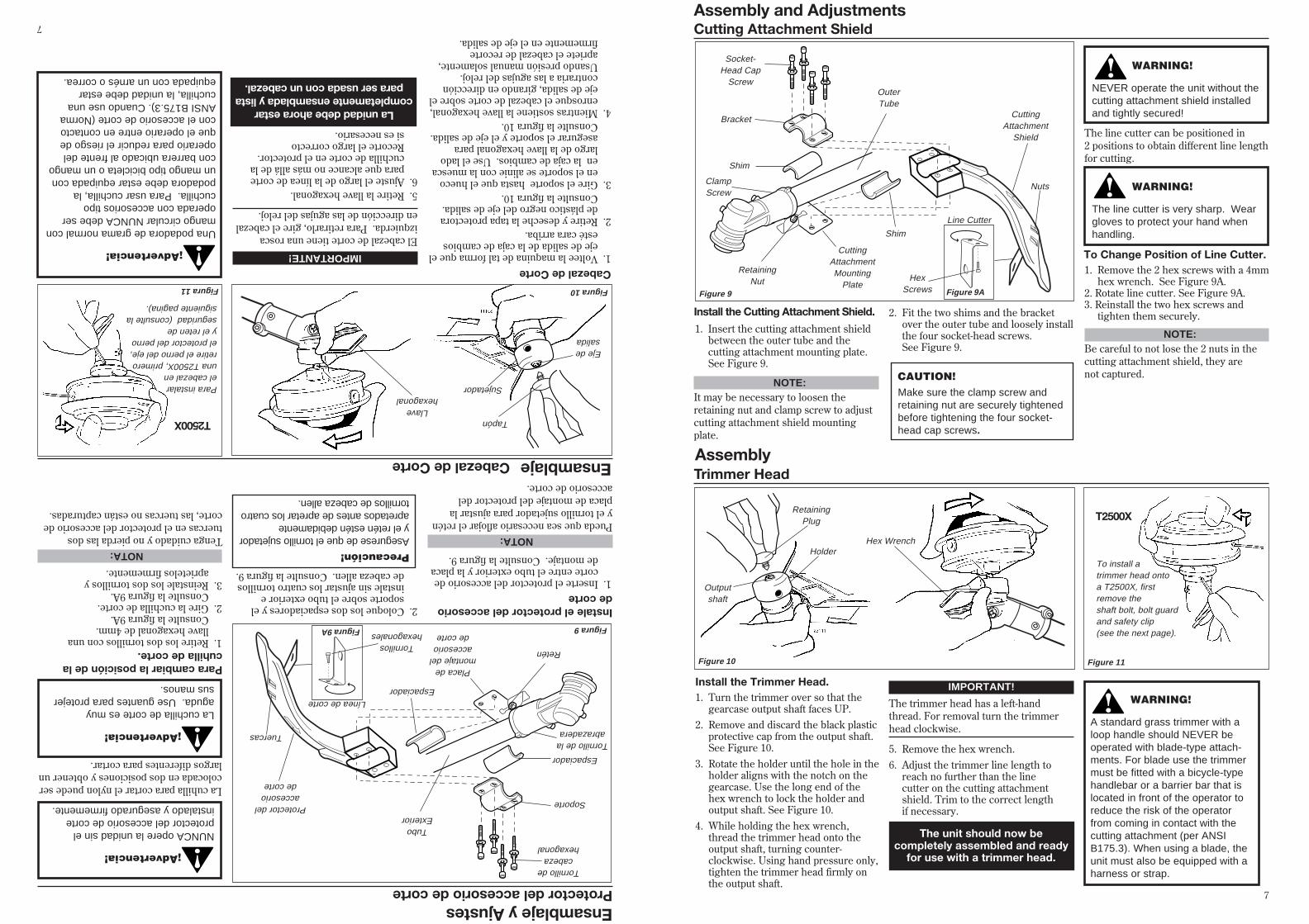
Figure 9
CuttingAttachment
Shield
OuterTube
Socket-Head Cap
Screw
Bracket
Shim
ClampScrew
Shim
RetainingNut
CuttingAttachmentMounting
Plate
Cutting Attachment ShieldAssembly and Adjustments
Line Cutter
Figure 9A
HexScrews
Nuts
Install the Cutting Attachment Shield.
1. Insert the cutting attachment shieldbetween the outer tube and thecutting attachment mounting plate.See Figure 9.
WARNING!
NEVER operate the unit without thecutting attachment shield installedand tightly secured!
CAUTION!Make sure the clamp screw andretaining nut are securely tightenedbefore tightening the four socket-head cap screws.
NOTE:It may be necessary to loosen theretaining nut and clamp screw to adjustcutting attachment shield mountingplate.
2. Fit the two shims and the bracketover the outer tube and loosely installthe four socket-head screws.See Figure 9.
WARNING!
The line cutter is very sharp. Weargloves to protect your hand whenhandling.
To Change Position of Line Cutter.1. Remove the 2 hex screws with a 4mm
hex wrench. See Figure 9A.2. Rotate line cutter. See Figure 9A.3. Reinstall the two hex screws and
tighten them securely.
NOTE:Be careful to not lose the 2 nuts in thecutting attachment shield, they arenot captured.
The line cutter can be positioned in2 positions to obtain different line lengthfor cutting.
Trimmer Head
Install the Trimmer Head.1. Turn the trimmer over so that the
gearcase output shaft faces UP.2. Remove and discard the black plastic
protective cap from the output shaft.See Figure 10.
3. Rotate the holder until the hole in theholder aligns with the notch on thegearcase. Use the long end of thehex wrench to lock the holder andoutput shaft. See Figure 10.
4. While holding the hex wrench,thread the trimmer head onto theoutput shaft, turning counter-clockwise. Using hand pressure only,tighten the trimmer head firmly onthe output shaft.
IMPORTANT!
The trimmer head has a left-handthread. For removal turn the trimmerhead clockwise.
5. Remove the hex wrench.6. Adjust the trimmer line length to
reach no further than the linecutter on the cutting attachmentshield. Trim to the correct lengthif necessary.
Assembly
Figure 10
WARNING!
A standard grass trimmer with aloop handle should NEVER beoperated with blade-type attach-ments. For blade use the trimmermust be fitted with a bicycle-typehandlebar or a barrier bar that islocated in front of the operator toreduce the risk of the operatorfrom coming in contact with thecutting attachment (per ANSIB175.3). When using a blade, theunit must also be equipped with aharness or strap.
The unit should now becompletely assembled and ready
for use with a trimmer head.
Holder
Outputshaft
RetainingPlug T2500X
Figure 11
To install atrimmer head ontoa T2500X, firstremove theshaft bolt, bolt guardand safety clip(see the next page).
Hex Wrench
7
1025
Figura 9
Protector delaccesoriode corte
TuboExterior
Tornillo decabeza
hexagonal
Soporte
Espaciador
Tornillo de laabrazadera
Espaciador
Retén
Placa demontaje delaccesoriode corte
Protector del accesorio de corteEnsamblaje y Ajustes
Línea de corte
Figura 9A
Tornilloshexagonales
Tuercas
Instale el protector del accesoriode corte1.Inserte el protector del accesorio de
corte entre el tubo exterior y la placade montaje. Consulte la figura 9.
¡Advertencia!
NUNCA opere la unidad sin elprotector del accesorio de corteinstalado y asegurado firmemente.
Precaución!Asegurese de que el tornillo sujetadory el retén estén debidamenteapretados antes de apretar los cuatrotornillos de cabeza allen.
NOTA:Pueda que sea necesario aflojar el retény el tornillo sujetador para ajustar laplaca de montaje del protector delaccesorio de corte.
2.Coloque los dos espaciadores y elsoporte sobre el tubo exterior einstale sin ajustar los cuatro tornillosde cabeza allen. Consulte la figura 9.
¡Advertencia!
La cuchilla de corte es muyaguda. Use guantes para protejersus manos.
Para cambiar la posición de lacuhilla de corte.1.Retire los dos tornillos con una
llave hexagonal de 4mm.Consulte la figura 9A.
2. Gire la cuchilla de corte.Consulte la figura 9A.
3. Reinstale los dos tornillos yaprietelos firmemente.
NOTA:Tenga cuidado y no pierda las dostuercas en el protector del accesorio decorte, las tuercas no están capturadas.
La cuhilla para cortar el nylon puede sercolocada en dos posiciones y obtener unlargos diferentes para cortar.
Cabezal de Corte1.Voltee la maquina de tal forma que el
eje de salida de la caja de cambiosesté cara arriba.
2.Retire y deseche la tapa protectorade plástico negro del eje de salida.Consulte la figura 10.
3.Gire el soporte hasta que el huecoen el soporte se alinie con la muescaen la caja de cambios. Use el ladolargo de la llave hexagonal paraasegurar el soporte y el eje de salida.Consulte la figura 10.
4.Mientras sostiene la llave hexagonal,enrosque el cabezal de corte sobre eleje de salida, girando en direccióncontraria a las agujas del reloj.Usando presión manual solamente,apriete el cabezal de recortefirmemente en el eje de salida.
IMPORTANTE!
El cabezal de corte tiene una roscaizquierda. Para retirarlo, gire el cabezalen dirección de las agujas del reloj.
5.Retire la llave hexagonal.6.Ajuste el largo de la línea de corte
para que alcance no más allá de lacuchilla de corte en el protector.Recorte el largo correctosi es necesario.
Ensamblaje
Figura 10
¡Advertencia!
Una podadora de grama normal conmango circular NUNCA debe seroperada con accesorios tipocuchilla. Para usar cuchilla, lapodadora debe estar equipada conun mango tipo bicicleta o un mangocon barrera ubicado al frente deloperario para reducir el riesgo deque el operario entre en contactocon el accesorio de corte (NormaANSI B175.3). Cuando use unacuchilla, la unidad debe estarequipada con un arnés o correa.
La unidad debe ahora estarcompletamente ensamblada y lista
para ser usada con un cabezal.
Sujetador
Eje desalida
TapónT2500X
Figura 11
Para instalarel cabezal enuna T2500X, primeroretire el perno del eje,el protector del pernoy el reten deseguridad (consulte lasiguiente pagina).
Llavehexagonal
7
Cabezal de Corte
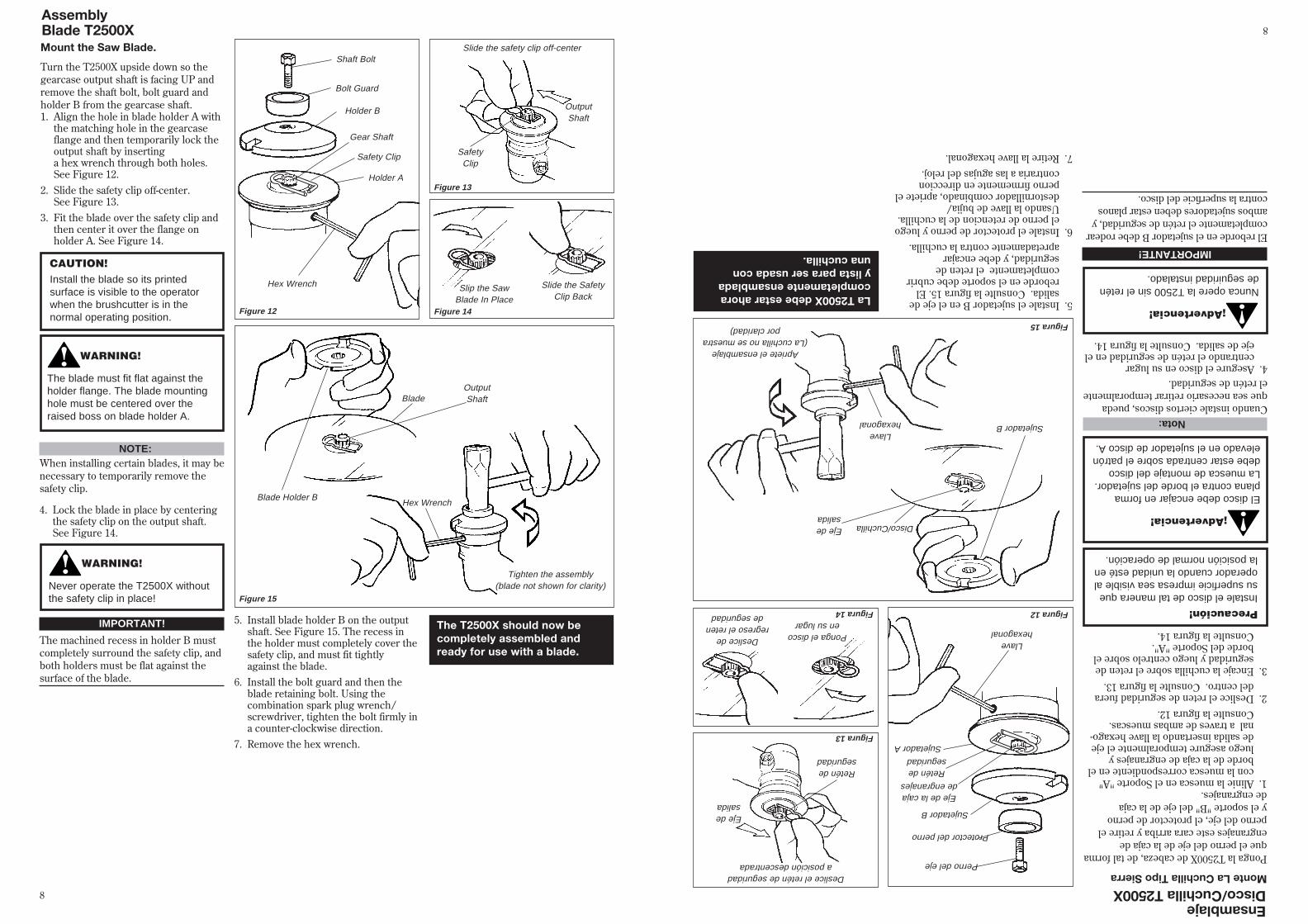
Turn the T2500X upside down so thegearcase output shaft is facing UP andremove the shaft bolt, bolt guard andholder B from the gearcase shaft.1. Align the hole in blade holder A with
the matching hole in the gearcaseflange and then temporarily lock theoutput shaft by insertinga hex wrench through both holes.See Figure 12.
2. Slide the safety clip off-center.See Figure 13.
3. Fit the blade over the safety clip andthen center it over the flange onholder A. See Figure 14.
Mount the Saw Blade. Slide the safety clip off-center
Slip the SawBlade In Place
Slide the SafetyClip Back
AssemblyBlade T2500X
Shaft Bolt
Bolt Guard
Holder B
Gear Shaft
Holder A
Hex Wrench
Figure 12
Blade
Hex Wrench
NOTE:When installing certain blades, it may benecessary to temporarily remove thesafety clip.
CAUTION!Install the blade so its printedsurface is visible to the operatorwhen the brushcutter is in thenormal operating position.
WARNING!
The blade must fit flat against theholder flange. The blade mountinghole must be centered over theraised boss on blade holder A.
WARNING!
Never operate the T2500X withoutthe safety clip in place!
4. Lock the blade in place by centeringthe safety clip on the output shaft.See Figure 14.
The T2500X should now becompletely assembled andready for use with a blade.
IMPORTANT!
The machined recess in holder B mustcompletely surround the safety clip, andboth holders must be flat against thesurface of the blade.
5. Install blade holder B on the outputshaft. See Figure 15. The recess inthe holder must completely cover thesafety clip, and must fit tightlyagainst the blade.
6. Install the bolt guard and then theblade retaining bolt. Using thecombination spark plug wrench/screwdriver, tighten the bolt firmly ina counter-clockwise direction.
7. Remove the hex wrench.
Blade Holder B
Tighten the assembly(blade not shown for clarity)
Figure 15
Safety Clip SafetyClip
OutputShaft
Figure 13
Figure 14
OutputShaft
8
Ponga la T2500X de cabeza, de tal formaque el perno del eje de la caja deengranajes este cara arriba y retire elperno del eje, el protector de pernoy el soporte "B" del eje de la cajade engranajes.1.Alinie la muesca en el Soporte "A"
con la muesca correspondiente en elborde de la caja de engranajes yluego asegure temporalmente el ejede salida insertando la llave hexago-nal a traves de ambas muescas.Consulte la figura 12.
2.Deslice el reten de seguridad fueradel centro. Consulte la figura 13.
3.Encaje la cuchilla sobre el reten deseguridad y luego centrelo sobre elborde del Soporte "A".Consulte la figura 14.
Monte La Cuchilla Tipo SierraDeslice el retén de seguridada posición descentrada
Ponga el discoen su lugar
Deslice deregreso el reten
de seguridad
EnsamblajeDisco/Cuchilla T2500X
Perno del eje
Protector del perno
Sujetador B
Eje de la cajade engranajes
Sujetador A
Llavehexagonal
Figura 12
Disco/Cuchilla
Llavehexagonal Nota:
Cuando instale ciertos discos, puedaque sea necesario retirar temporalmenteel retén de seguridad.
Precaución!Instale el disco de tal manera quesu superficie impresa sea visible aloperador cuando la unidad esté enla posición normal de operación.
¡Advertencia!
El disco debe encajar en formaplana contra el borde del sujetador.La muesca de montaje del discodebe estar centrada sobre el patrónelevado en el sujetador de disco A.
¡Advertencia!
Nunca opere la T2500 sin el reténde seguiridad instalado.
4.Asegure el disco en su lugarcentrando el retén de seguridad en eleje de salida. Consulte la figura 14.
La T2500X debe estar ahoracompletamente ensambladay lista para ser usada conuna cuchilla.
IMPORTANTE!
El reborde en el sujetador B debe rodearcompletamente el retén de seguridad, yambos sujetadores deben estar planoscontra la superficie del disco.
5.Instale el sujetador B en el eje desalida. Consulte la figura 15. Elreborde en el soporte debe cubrircompletamente el reten deseguridad, y debe encajarapretadamente contra la cuchilla.
6.Instale el protector de perno y luegoel perno de retencion de la cuchilla.Usando la llave de bujia/destornillador combinado, apriete elperno firmemente en direccioncontraria a las agujas del reloj.
7.Retire la llave hexagonal.
Sujetador B
Apriete el ensamblaje(La cuchilla no se muestra
por claridad) Figura 15
Retén deseguridad
Retén deseguridad
Eje desalida
Figura 13
Figura 14
Eje desalida
8
XST013
XST012
XST011
Primer BulbReturn Tube
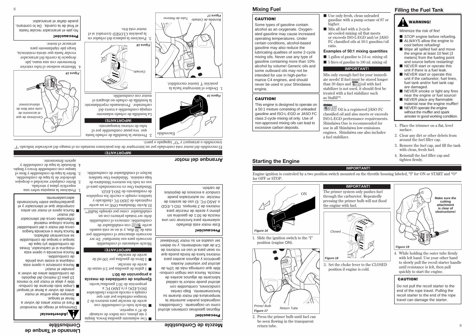
Starting the Engine
4. While holding the outer tube firmlywith left hand. Use your other handto slowly pull the recoil starter handleuntil resistance is felt, then pullquickly to start the engine.
1. Slide the ignition switch to the “I”position (engine ON).
2. Press the primer bulb until fuel canbe seen flowing in the transparentreturn tube.
3. Set the choke lever to the CLOSEDposition if engine is cold.
Make sure thecutting
attachmentis clear of
obstructions!
IMPORTANT!
Engine ignition is controled by a two position switch mounted on the throttle housing labeled, "I" for ON or START and "O"for OFF or STOP.
Figure 16
Figure 18
Figure 17
Figure 19
Closed
IMPORTANT!The primer system only pushes fuelthrough the carburetor. Repeatedlypressing the primer bulb will not floodthe engine with fuel.
CAUTION!
Do not pull the recoil starter to theend of the rope travel. Pulling therecoil starter to the end of the ropetravel can damage the starter.
Mixing Fuel
1. Place the trimmer on a flat, levelsurface.
2. Clear any dirt or other debris fromaround the fuel filler cap.
3. Remove the fuel cap, and fill the tankwith clean, fresh fuel.
4. Reinstall the fuel filler cap andtighten firmly.
Filling the Fuel Tank
WARNING!
Minimize the risk of fire!
■ STOP engine before refueling.■ ALWAYS allow the engine to
cool before refueling!■ Wipe all spilled fuel and move
the engine at least 10 feet (3meters) from the fueling pointand source before restarting!
■ NEVER start or operate thisunit if there is a fuel leak.
■ NEVER start or operate thisunit if the carburetor, fuel lines,fuel tank and/or fuel tank capare damaged.
■ NEVER smoke or light any firesnear the engine or fuel source!
■ NEVER place any flammablematerial near the engine muffler!
■ NEVER operate the enginewithout the muffler and sparkarrester in good working condition.
ON
CAUTION!This engine is designed to operate ona 50:1 mixture consisting of unleadedgasoline and ISO-L-EGD or JASO FCclass 2-cycle mixing oil only. Use ofnon-approved mixing oils can lead toexcessive carbon deposits.
CAUTION!Some types of gasoline containalcohol as an oxygenate. Oxygen-ated gasoline may cause increasedoperating temperatures. Undercertain conditions, alcohol-basedgasoline may also reduce thelubricating qualities of some 2-cyclemixing oils. Never use any type ofgasoline containing more than 10%alcohol by volume! Generic oils andsome outboard oils may not beintended for use in high-perfor-mance C4 engines, and shouldnever be used in your Shindaiwaengine.
■ Use only fresh, clean unleadedgasoline with a pump octane of 87 orhigher.
■ Mix all fuel with a 2-cycleair-cooled mixing oil that meetsor exceeds ISO-L-EGD and/or JASOFC classified oils at 50:1 gasoline/oilratio.
Examples of 50:1 mixing quantities■ 1 gallon of gasoline to 2.6 oz. mixing oil■ 5 liters of gasoline to 100 ml. mixing oil
IMPORTANT!
Mix only enough fuel for your immedi-ate needs! If fuel must be stored longerthan 30 days and oil with fuelstabilizer is not used, it should first betreated with a fuel stabilizer suchas StaBil™.
Oil is a registered JASO FCclassified oil and also meets or exceedsISO-L-EGD performance requirements.Shindaiwa One is recommended foruse in all Shindaiwa low emissionsengines. Shindaiwa one also includesa fuel stabilizer.
9
XST013
XST012
XST011
Bombilla de CebadoTubo de Retorno
Arranque del motor
4.Mientras sostiene el tubo exteriorfirmemente con una mano, jaledespacio la cuerda del arrancadorrecular hasta que sienta resistencia,luego jale rápidamente paraarrancar el motor.
1.Deslice el interruptor hacia laposición ‘I’ (motor encendido).
2.Presione la bombilla de cebado hastaque vea pasar combustible por eltubo de retorno transparente.
3.Posicione la palanca del cebador enla posición CLOSED (cerrado) si elmotor está frío.
Cerciórese de queel accesorio de
corte esté libre deobstrucciones!
IMPORTANTE!
Figura 16
Figura 18
Figura 17
Figura 19 Cerrado
IMPORTANTE!
La bombilla de cebado solamenteempuja combustible a travéz delcarburador. Presionando repetidamentela bombilla de cebado no ahogará elmotor con combustible.
Precaución!No jale el arrancador recular hastael final de la cuerda. De lo contrario,puede dañar el arrancador.
Mezcla de Combustible
1.Posicione la maquina sobre unasuperficie plana y nivelada.
2.Retire cualquier suciedad o despojosalrededor de la tapa de combustible.
3.Retire la tapa de combustible y llene eltanque con combustible fresco y limpio.
4.Reinstale la tapa de combustible yapriete firmemente.
Llenando el Tanque deCombustible
¡Advertencia!
Disminuya el riesgo de incendios!
Encendido
Precaución!Este motor está diseñadosolamente para funcionar con unamezcla de 50:1 de gasolina sinplomo y aceite de mezclar paramotores de 2 tiempos. ISO-L-EGDo JASO FC. El uso de aceites demezclar no autorizados puedeconducir a excesos de depósitosde carbón.
Precaución!Algunas gasolinas contienen alcoholcomo un oxigenante. Combustiblesoxigenados pueden aumentar latemperatura del motor durante sufuncionamiento. Bajo ciertascondiciones, combustible conalcohol puede reducir la calidadlubricante de algunos aceites demezcla. Nunca use ningún combus-tible que contenga más de 10% dealcohol por volumén! Aceitesgenéricos y algunos aceites paramotores fuera de borda pueda queno sean para el uso en motores deC4 de alto rendimiento, y no debenser usados en su motor Shindaiwa!
■Use solamente gasolina fresca, limpiay sin plomo, con índice de octanajede 87 o superior.
■Mezcle todo el combustible conaceite de mezclar para motores de 2tiempos enfriados por aire quecumpla o exceda aceites clasificadosISO-L-EDG y/o JASO FC aproporción de 50:1 gasolina/aceite.
Ejemplos de cantidades de mezclaa proporción de 50:1■1 galón de gasolina por 2.6 onzas de
aceite de mezclar.■5 litros de gasolina por 100 ml de
aceite de mezclar.IMPORTANTE!
Mezcle solamente el combustiblenecesario para uso inmediato! De sernecesario almacenar el combustible pormás de 30 días, y si no se está usandoaceite con estabilizador decombustible, entonces el combustibledebe ser tratado primero con unestabilizador como por ejemplo StaBil™.
El Aceite Shindaiwa ONE es un aceiteregistrado de JASO FC clasificado ytambien cumple o excede los requisitosde rendimiento de ISO-L-EGD.Shindaiwa One es recomendado para eluso en todo los motores Shindaiwa debaja emisión. Shindaiwa One tambienincluye el estabilizador de combustible.
■Pare el motor antes de volver allenar el tanque.
■Siempre deje enfriar el motorantes de volver a llenar el tanque!
■Limpie todo derrame de combus-tible y aleje el motor por lo menos10 pies (3 metros) del depósitode combustible antes de volver aprender el motor!
■Nunca comienze u opere estamáquina si existe una péridade combustible.
■Nunca encienda u opere estamáquina si el carburador, líneasde combustible y/o tapa detanque o tanque de combustiblese encuentran dañados.
■Nunca fume o encienda fuegoscerca del motor o del combustible!
■Nunca coloque materialinflamable cerca del silenciadordel motor!
■Nunca opere el motor sin antescomprobar que el silenciador y elguardachispas estén funcionandoadecuadamente.
El encendido del motor está controlado por un interruptor de dos posiciones montado en el mango del acelerador indicado “I”(encendido o arranque) y “O” (apagado o pare).
9

XST012
Starting the Engine (continued)
WARNING!
Never start the engine from theoperating position.
WARNING!
The cutting attachment may rotatewhen the engine is started!
When the Engine Starts...■ After the engine starts, allow the
engine to warm up at idle 2 or 3minutes before operating the unit.
■ After the engine is warm, pickup the unit and clip on the shoulderstrap if so equipped. See page 11.
■ Advancing the throttle makes thecutting attachment turn faster;releasing the throttle permits theattachment to stop turning. If thecutting attachment continues torotate when the engine returns toidle, carburetor idle speed shouldbe adjusted (see "Adjusting EngineIdle" below).
IMPORTANT!
If the engine fails to start after severalattempts with the choke in the closedposition, the engine may be floodedwith fuel. If flooding is suspected,move the choke lever to the openposition and repeatedly pull the recoilstarter to remove excess fuel and startthe engine. If the engine still fails tostart, refer to the troubleshootingsection of this manual.
5. When the engine starts, slowly movethe choke lever to the "OPEN"position. See Figure 20. (If theengine stops after the initial start,close the choke and restart.)
Figure 20
Open
XST015
Idle the engine briefly before stopping(about 2 minutes), then slide theignition switch to the “O” (Engine OFF)position.
Stopping the Engine
Adjusting Engine Idle
Figure 21
Figure 22Idle Adjusting
Screw
OFF
The engine must return to idle speedwhenever the throttle lever is released.Idle speed is adjustable, and must be setlow enough to permit the engine clutchto disengage the cutting attachment.
Idle Speed Adjustment
WARNING!
The cutting attachment mustNEVER rotate at engine idle! If theidle speed cannot be adjusted bythe procedure described here,return the trimmer to yourShindaiwa dealer for inspection.
1. Place the trimmer on the ground,then start the engine, and then allowit to idle 2-3 minutes until warm.
2. If the attachment rotates when theengine is at idle, reduce the idlespeed by turning the idle adjustmentscrew counter-clockwise.See Figure 22.
3. If a tachometer is available, the engineidle speed should be final adjusted to3,200 (±300) rpm (min-1).
4. Carburetor fuel mixture adjustmentsare preset at factory and cannot beserviced in the field.
10
XST012
XST015
Arranque del motor (cont.)
¡Advertencia!
Nunca arranque el motor desde laposición de operación.
¡Advertencia!
El accesorio de corte pueda quegire cuando encienda el motor!
Cuando arranca el motor…■Después de que arranque el motor,
permita que caliente en marchamínima por 2 ó 3 minutos antes deusar la máquina.
■Después de que caliente el motor,levante la máquina y asegure elarnés si así está equipada.Consulte la página 11.
■Adelantando el acelerador hace queel accesorio de corte gire más rápido;liberando el acelerador permite queel accesorio pare de girar. Si elaccesorio de corte continua girandocuando el motor regresa a marchamínima, la velocidad mínima delcarburador debe ser ajustada.(Consulte “Ajuste de MarchaMínima” a continuación)
IMPORTANTE!
Si el motor falla en arrancar después devarios intentos con la palanca delcebador en posicion cerrada, puede queel motor esté ahogado con combustible.Si esto se sospecha, mueva la palancadel cebador a la posición abierta yrepetidamente jale el arrancador recularpara remover el exceso de combustibley para arrancar el motor. Si aún falla enarrancar el motor, consulte el guíadiagnóstico de este manual.
5. Cuando arranque el motor, muevadespacio la palanca del cebador a laposición “OPEN” (abierto). Consultela figura 16. (Si el motor paradespués del arranque inicial,cierre la palanca del cebador yvuelva arrancar).
Figura 20
Abierto
Ponga el motor en marcha mínima pordos o tres minutos antes de apagarlo,luego deslice el interruptor de ignición ala posición “O” (motor apagado)
Parada del motor
Ajuste de Marcha Mínima del Motor
Figura 21
Figura 22Tornillo de
marcha mínima
Apagado
El motor debe retornar a marchamínima cuando la palanca del aceleradores liberada. La marcha mínima esajustable y debe ser suficientementemínima para permitir que el embraguedel motor libere el accesorio de corte.
Ajuste de Marcha Mínima
¡Advertencia!
El accesorio de corte NUNCA debegirar en marcha mínima! Si lamarcha mínima no puede serajustada por el procedimientodescrito aquí, entronces devuelva lapodadora a su distribuidorShindaiwa para inspección.
1.Coloque la podadora en el suelo,luego encienda el motor y déjelofuncionar en marcha mínima durante2 ó 3 minutos hasta que caliente.
2.Si el accesorio de corte gira mientrasel motor está en marcha mínima,reduzca la marcha minima, girando eltornillo de ajuste de marcha mínimaen el sentido contrario a las agujasdel reloj. Consulte la figura 22.
3.Si tiene un tacómetro disponible, lamarcha mínima se debe ajustar a3,200 rpm (±300) rpm (min-1).
4.Los ajustes de mezcla de carburadorson prefijados en la fábrica y nopueden ser cambiados en el campo.
10
Your Shindaiwa unit may be equippedwith one of several Shindaiwa trimmerhead models, each with features forspecific applications and/or operationalrequirements.
NOTE:For proper operation, always refer to theinstructions accompanying the trimmerhead being used. Available trimmerhead styles include:
■ Semi-automatic. Trimmer line isindexed when the operator taps thetrimmer head on the ground duringoperation.
■ Manual. The operator indexes linemanually with the grass trimmerstopped.
■ Fixed. The operator must stop theunit and add new lengths of trimmerline manually.
■ Flail. This device, designed forclearing weeds and light brush,features three nylon blades attachedto the head by pivots.
NOTE: Additional hardware may be required
to mount the Fixed Line or the Flailtype trimmer heads.
Cutting Grass—Units equipped with a trimmer head.
CAUTION!Operation at low RPM can lead topremature clutch failure.
Trimming and Mowing Grass
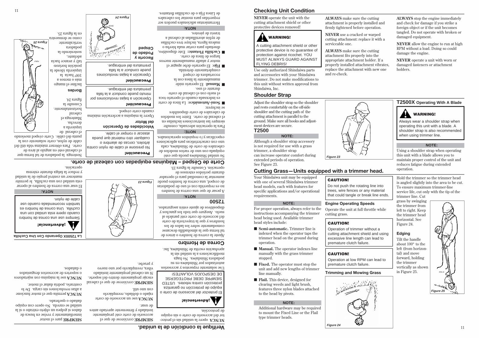
Hold the trimmer so the trimmer headis angled slightly into the area to be cut.To ensure maximum trimmer-lineservice life, cut only with the tip of thetrimmer line. Cutgrass by swingingthe trimmer fromleft to right. Keepthe trimmer headhorizontal. SeeFigure 24.
EdgingTilt the handleabout 100° to theleft (from horizon-tal) and moveforward, holdingthe trimmervertically as shownin Figure 25.
Figure 24
Figure 25
Checking Unit ConditionNEVER operate the unit with thecutting attachment shield or otherprotective devices removed!
WARNING!
A cutting attachment shield or otherprotective device is no guarantee ofprotection against ricochet. YOUMUST ALWAYS GUARD AGAINSTFLYING DEBRIS!
Use only authorized Shindaiwa partsand accessories with your Shindaiwatrimmer. Do not make modifications tothis unit without written approval fromShindaiwa, Inc.
Shoulder StrapAdjust the shoulder strap so the shoulderpad rests comfortably on the off-sideshoulder and the cutting path of thecutting attachment is parallel to theground. Make sure all hooks and adjust-ment devices are secure.T2500
Figure 23
CAUTION!Operation of trimmer without acutting attachment shield and usingexcessive line length can lead topremature clutch failure.
ALWAYS make sure the cuttingattachment is properly installed andfirmly tightened before operation.
NEVER use a cracked or warpedcutting attachment: replace it with aserviceable one.
ALWAYS make sure the cuttingattachment fits properly into theappropriate attachment holder. If aproperly installed attachment vibrates,replace the attachment with new oneand re-check.
ALWAYS stop the engine immediatelyand check for damage if you strike aforeign object or if the unit becomestangled. Do not operate with broken ordamaged equipment.
NEVER allow the engine to run at highRPM without a load. Doing so coulddamage the engine.
NEVER operate a unit with worn ordamaged fasteners or attachmentholders.
CAUTION!Do not push the rotating line intotrees, wire fences or any materialthat could tangle or break line ends.
Engine Operating SpeedsOperate the unit at full throttle whilecutting grass.
NOTE:Although a shoulder strap accessoryis not required for use with a grasstrimmer, a shoulder strapcan increase operator comfort duringextended periods of operation.See Figure 23.
WARNING!
Always wear a shoulder strap whenoperating this unit with a blade. Ashoulder strap is also recommendedwhen using trimmer line.
NOTE:Using a shoulder strap when operatingthis unit with a blade allows you tomaintain proper control of the unit andreduces fatigue during extendedoperation.
T2500X Operating With A Blade
11
Su unidad Shindaiwa pueda que estéequipada con uno de varios modelos decabezales de corte de Shindaiwa, cadauno con caracteristicas para aplicacionesespecíficas y/o requisitos operacionales.
Corte de Césped – Máquinas equipadas con cabezal de corte.
Precaución!Operación a bajas revolucionespuede conducir a la fallaprematura del embrague.
Recorte yPodado deCésped
Sostenga la podadora de tal forma queel cabezal esté en angulo al área decorte. Para obtener máxima vida útil delcable de nylon, corte solamente con lapunta del cable. Corte césped moviendoel cabezal deizquierda aderecha.Mantenga elcabezalhorizontalmente.Consulte lafigura 24.
BordesIncline el mangomás o menos a100º hacia laizquierda (desde laposición horizon-tal) y avance haciaadelante,sosteniendo lapodadoraverticalmentecomo se demuestraen la figura 25.
Figura 25
Verifique la condición de la unidad.NUNCA opere la unidad sin el protec-tor del accesorio de corte o sin equipode protección.
¡Advertencia!
El protector del accesorio de corte oequipo de protección no garantizaprotección contra rebotes. USTEDSIEMPRE DEBE PROTEGERSEDE DESPOJOS VOLANTES!
Use solamente repuestos y accesoriosautorizados por Shindaiwa en supodadora Shindaiwa. No hagamodificaciones a la unidad sin laaprobación escrita de Shindaiwa, Inc.
Correa de HombroAjuste la correa de hombro o árnes detal forma que la almohadilla descansecomodamente sobre los lados de loshombros y que la trayectoria de cortedel accesorio de corte esté paralelo alsuelo. Asegure que todo los ganchos ydispositivos de ajuste estén asegurados.
T2500
Figura 23
Precaución!Operación a bajas revoluciones porminuto puede conducir a la fallaprematura del embrague.
SIEMPRE cerciórese de que elaccesorio de corte esté propiamenteinstalado y firmemente apretado antesde usar.
NUNCA use un accesorio de corterajado o doblado, reemplácelocon uno util.
SIEMPRE cerciórese de que el cabezalencaje propiamente dentro del soporte.Si un cabezal propiamente instaladovibra, reemplácelo por uno nuevoy pruebe.
SIEMPRE pare el motorinmediatamente y revise en busca dedaños si golpea un objeto extraño o si launidad se enreda. No opere con equipodañado o quebrado.
NUNCA permita que el motor funcionea altas revoluciones sin carga. De locontrario, podría dañar el motor.
NUNCA use la máquina con sujetadoreso soportes de accesorios desgastadoso dañados.
NOTA:A pesar de que una correa de hombrono es requerida con el uso de podadorasde cesped, una correa de hombro puedeaumentar la comodiad para el operadordurante periódos extensos deoperación. Consulte la figura 23.
¡Advertencia!
Siempre use una correa de hombrocuando opere esta unidad con unacuchilla. Una correa de hombro estambién recomendada cuando usecable de nylon.
NOTA:El usar una correa de hombro al operaresta unidad con una cuchilla, le permitemantener un control propio de la unidady reduce la fatiga durante extensaoperación.
La T2500X Operando Con Una Cuchilla
NOTE:Para la operación adecuada, consultesiempre las instrucciones incluídas enel cabezal de corte. Entre los modelosde cabezales de corte disponiblesse incluyen:
NOTA: Herramientas adicionales pueden ser
requeridas para montar los cabezalesde Línea Fija o de cuchillas flotantes.
Precaución!No presione el cable de nylon contraárboles, cercas de alambre ocualquier otro material que puedaatascar o romper el cable.
■Semi-Automático: La línea de cortees indexsada cuando el operario tocael suelo con el cabezal de cortedurante el uso.
■Manual: El operario midemanualmente la línea con larecortadora de céspedcompletamente detenida.
■Fijo: El operario debe apagar elmotor y añadir manualmente nuevoslargos de línea de corte.
■Cuchilla Flotante: Este dispositivo,diseñado para cortar mala hierba omaleza ligera, incluye tres cuchillasde nylón atornilladas al cabezal atravéz de pivotes.
Figura 24
Velocidades de Operacióndel MotorOpere la máquina a aceleración máximacuando corte césped.
11
1060
TenO’Clock
SevenO’Clock
OK To Cut
BladeRotation
DO NOT CUT
FiveO’Clock
WARNING!
n Before working with a blade-equipped unit, always inspectand clean the area of objectsthat could interfere with ordamage the blade.
n Never use a blade near side-walks, fence posts, buildings orother objects that could causeinjury or damage.
n Never use a blade for purposesother than those for which it wasdesigned.
n Whenever you strike a hardobject with a blade, always stopthe brushcutter and carefullyinspect the blade for damage.NEVER OPERATE THEBRUSHCUTTER WITH ADAMAGED BLADE!
n A blade-equipped unit must beequipped with a bicycle-typehandlebar or barrier bar as wellas a harness or shoulder strap.
n Always make sure the cuttingattachment shield is properlyinstalled before operatingthis unit.
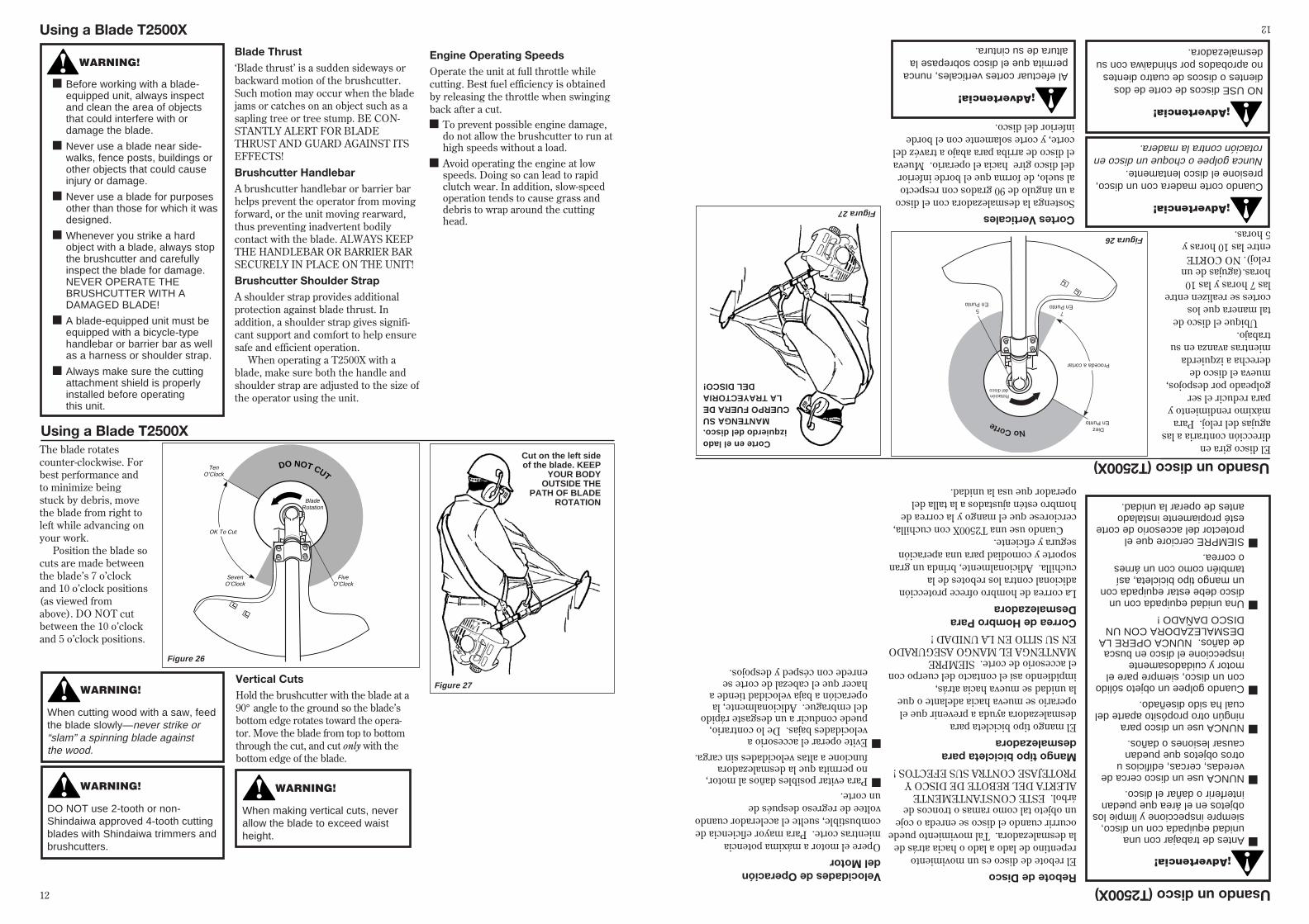
Using a Blade T2500XBlade Thrust‘Blade thrust’ is a sudden sideways orbackward motion of the brushcutter.Such motion may occur when the bladejams or catches on an object such as asapling tree or tree stump. BE CON-STANTLY ALERT FOR BLADETHRUST AND GUARD AGAINST ITSEFFECTS!Brushcutter HandlebarA brushcutter handlebar or barrier barhelps prevent the operator from movingforward, or the unit moving rearward,thus preventing inadvertent bodilycontact with the blade. ALWAYS KEEPTHE HANDLEBAR OR BARRIER BARSECURELY IN PLACE ON THE UNIT!Brushcutter Shoulder StrapA shoulder strap provides additionalprotection against blade thrust. Inaddition, a shoulder strap gives signifi-cant support and comfort to help ensuresafe and efficient operation.
When operating a T2500X with ablade, make sure both the handle andshoulder strap are adjusted to the size ofthe operator using the unit.
Engine Operating SpeedsOperate the unit at full throttle whilecutting. Best fuel efficiency is obtainedby releasing the throttle when swingingback after a cut.n To prevent possible engine damage,
do not allow the brushcutter to run athigh speeds without a load.
n Avoid operating the engine at lowspeeds. Doing so can lead to rapidclutch wear. In addition, slow-speedoperation tends to cause grass anddebris to wrap around the cuttinghead.
The blade rotatescounter-clockwise. Forbest performance andto minimize beingstuck by debris, movethe blade from right toleft while advancing onyour work.
Position the blade socuts are made betweenthe blade’s 7 o’clockand 10 o’clock positions(as viewed fromabove). DO NOT cutbetween the 10 o’clockand 5 o’clock positions.
WARNING!
When cutting wood with a saw, feedthe blade slowly—never strike or“slam” a spinning blade againstthe wood.
WARNING!
DO NOT use 2-tooth or non-Shindaiwa approved 4-tooth cuttingblades with Shindaiwa trimmers andbrushcutters.
Vertical CutsHold the brushcutter with the blade at a90° angle to the ground so the blade’sbottom edge rotates toward the opera-tor. Move the blade from top to bottomthrough the cut, and cut only with thebottom edge of the blade.
Using a Blade T2500X
Figure 26
Cut on the left sideof the blade. KEEP
YOUR BODYOUTSIDE THE
PATH OF BLADEROTATION
Figure 27
WARNING!
When making vertical cuts, neverallow the blade to exceed waistheight.
12
Diez En Punto
7 En Punto
Proceda a cortar
Rotación del disco
NoCorte
5 En Punto
1060
¡Advertencia!
nAntes de trabajar con unaunidad equipada con un disco,siempre inspeccione y limpie losobjetos en el área que puedaninterferir o dañar el disco.
nNUNCA use un disco cerca deveredas, cercas, edificios uotros objetos que puedancausar lesiones o daños.
nNUNCA use un disco paraningún otro propósito aparte delcual ha sido diseñado.
nCuando golpee un objeto sólidocon un disco, siempre pare elmotor y cuidadosamenteinspeccione el disco en buscade daños. NUNCA OPERE LADESMALEZADORA CON UNDISCO DAÑADO !
nUna unidad equipada con undisco debe estar equipada conun mango tipo bicicleta, asítambién como con un árneso correa.
nSIEMPRE cerciore que elprotector del accesorio de corteesté propiamente instaladoantes de operar la unidad.
Usando un disco (T2500X)Rebote de DiscoEl rebote de disco es un movimientorepentino de lado a lado o hacia atrás dela desmalezadora. Tal movimiento puedeocurrir cuando el disco se enreda o cojeun objeto tal como ramas o troncos deárbol. ESTE CONSTANTEMENTEALERTA DEL REBOTE DE DISCO YPROTEJASE CONTRA SUS EFECTOS !Mango tipo bicicleta paradesmalezadoraEl mango tipo bicicleta paradesmalezadora ayuda a prevenir que eloperario se mueva hacia adelante o quela unidad se mueva hacia atrás,impidiendo así el contacto del cuerpo conel accesorio de corte. SIEMPREMANTENGA EL MANGO ASEGURADOEN SU SITIO EN LA UNIDAD !Correa de Hombro ParaDesmalezadoraLa correa de hombro ofrece protecciónadicional contra los rebotes de lacuchilla. Adicionalmente, brinda un gransoporte y comodiad para una aperaciónsegura y eficiente.
Cuando use una T2500X con cuchilla,cerciorese que el mango y la correa dehombro estén ajustados a la talla deloperador que usa la unidad.
Velocidades de Operacióndel MotorOpere el motor a máxima potenciamientras corte. Para mayor eficiencia decombustible, suelte el acelerador cuandovoltee de regreso después deun corte.nPara evitar posibles daños al motor,
no permita que la desmalezadorafuncione a altas velocidades sin carga.
nEvite operar el accesorio avelocidades bajas. De lo contrario,puede conducir a un desgaste rápidodel embrague. Adicionalmente, laoperación a baja velocidad tiende ahacer que el cabezal de corte seenrede con césped y despojos.
El disco gira endirección contraria a lasagujas del reloj. Paramáximo rendimiento ypara reducir el sergolpeado por despojos,mueva el disco dederecha a izquierdamientras avanza en sutrabajo.
Ubique el disco detal manera que loscortes se realizen entrelas 7 horas y las 10horas.(agujas de unreloj). NO CORTEentre las 10 horas y5 horas.
¡Advertencia!
Cuando corte madera con un disco,presione el disco lentamente.Nunca golpee o choque un disco enrotación contra la madera.
¡Advertencia!
NO USE discos de corte de dosdientes o discos de cuatro dientesno aprobados por shindaiwa con sudesmalezadora.
Cortes VerticalesSostenga la desmalezadora con el discoa un ángulo de 90 grados con respectoal suelo, de forma que el borde inferiordel disco gire hacia el operario. Muevael disco de arriba para abajo a travéz delcorte, y corte solamente con el bordeinferior del disco.
Usando un disco (T2500X)
Figura 26
Corte en el ladoizquierdo del disco.
MANTENGA SUCUERPO FUERA DE
LA TRAYECTORIADEL DISCO!
Figura 27
¡Advertencia!
Al efectuar cortes verticales, nuncapermita que el disco sobrepase laaltura de su cintura.
12
IMPORTANT!MAINTENANCE, REPLACEMENT ORREPAIR OF EMISSION CONTROLDEVICES AND SYSTEMS MAY BEPERFORMED BY ANY REPAIRESTABLISHMENT OR INDIVIDUAL;HOWEVER, WARRANTY REPAIRSMUST BE PERFORMED BY ADEALER OR SERVICE CENTERAUTHORIZED BY SHINDAIWAKOGYO CO., LTD. THE USE OFPARTS THAT ARE NOT EQUIVALENTIN PERFORMANCE AND DURABIL-ITY TO AUTHORIZED PARTS MAYIMPAIR THE EFFECTIVENESS OFTHE EMISSION CONTROL SYSTEMAND MAY HAVE A BEARING ON THEOUTCOME OF A WARRANTY CLAIM.
General Maintenance
WARNING!
Before performing any maintenance,repair or cleaning work on the unit,make sure the engine and cuttingattachment are completely stopped.Disconnect the spark plug wirebefore performing service ormaintnenance work.
WARNING!
Non-standard parts may not operateproperly with your unit and maycause damage and lead topersonal injury.
MufflerThis unit must never be operated with afaulty or missing spark arrester ormuffler. Make sure the muffler is wellsecured and in good condition. A wornor damaged muffler is a fire hazard andmay also cause hearing loss.
Spark PlugKeep the spark plug and wire connec-tions tight and clean.
FastenersMake sure nuts, bolts, and screws(except carburetor adjusting screws)are tight.
Daily MaintenancePrior to each work day, performthe following:
NOTE:Using non-standard replacementparts could invalidate your Shindaiwawarranty.
■ Remove dirt or debris from theengine, check the cooling fins and aircleaner for clogging and clean themas necessary.
10-Hour Maintenance
UnscrewFastener
Remove and cleanor replace
the element
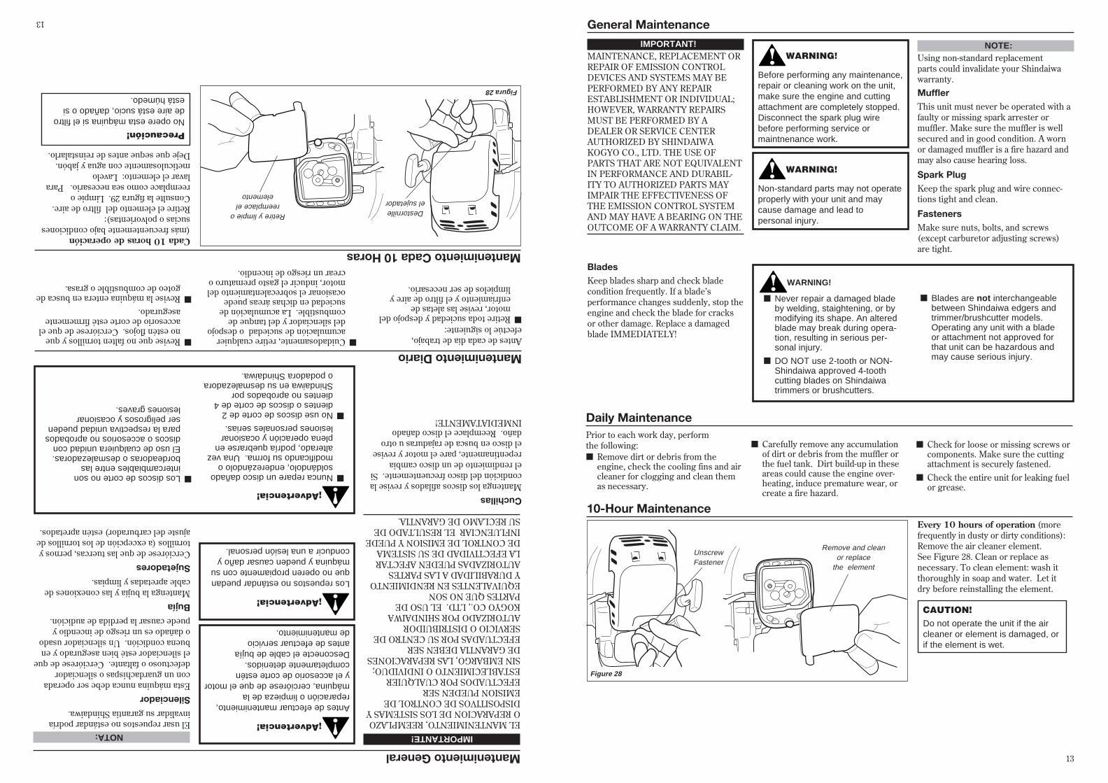
Every 10 hours of operation (morefrequently in dusty or dirty conditions):Remove the air cleaner element.See Figure 28. Clean or replace asnecessary. To clean element: wash itthoroughly in soap and water. Let itdry before reinstalling the element.
CAUTION!Do not operate the unit if the aircleaner or element is damaged, orif the element is wet.
Figure 28
■ Carefully remove any accumulationof dirt or debris from the muffler orthe fuel tank. Dirt build-up in theseareas could cause the engine over-heating, induce premature wear, orcreate a fire hazard.
■ Check for loose or missing screws orcomponents. Make sure the cuttingattachment is securely fastened.
■ Check the entire unit for leaking fuelor grease.
BladesKeep blades sharp and check bladecondition frequently. If a blade’sperformance changes suddenly, stop theengine and check the blade for cracksor other damage. Replace a damagedblade IMMEDIATELY!
WARNING!
■ Never repair a damaged bladeby welding, staightening, or bymodifying its shape. An alteredblade may break during opera-tion, resulting in serious per-sonal injury.
■ DO NOT use 2-tooth or NON-Shindaiwa approved 4-toothcutting blades on Shindaiwatrimmers or brushcutters.
■ Blades are not interchangeablebetween Shindaiwa edgers andtrimmer/brushcutter models.Operating any unit with a bladeor attachment not approved forthat unit can be hazardous andmay cause serious injury.
13
IMPORTANTE!
EL MANTENIMIENTO, REEMPLAZOO REPARACION DE LOS SISTEMAS YDISPOSITIVOS DE CONTROL DEEMISION PUEDEN SEREFECTUADOS POR CUALQUIERESTABLECIMIENTO O INDIVIDUO;SIN EMBARGO, LAS REPARACIONESDE GARANTIA DEBEN SEREFECTUADAS POR SU CENTRO DESERVICIO O DISTRIBUIDORAUTORIZADO POR SHINDAIWAKOGYO CO., LTD. EL USO DEPARTES QUE NO SONEQUIVALENTES EN RENDIMIENTOY DURABILIDAD A LAS PARTESAUTORIZADAS PUEDEN AFECTARLA EFECTIVIDAD DE SU SISTEMADE CONTROL DE EMISION Y PUEDEINFLUENCIAR EL RESULTADO DESU RECLAMO DE GARANTIA.
Mantenimiento General
SilenciadorEsta máquina nunca debe ser operadacon un guardachispas o silenciadordefectuoso o faltante. Cerciórese de queel silenciador esté bien asegurado y enbuena condición. Un silenciador usadoo dañado es un riesgo de incendio ypuede causar la perdida de audición.
BujíaMantenga la bujía y las conexiones decable apretadas y limpias.
SujetadoresCerciórese de que las tuercas, pernos ytornillos (a excepción de los tornillos deajuste del carburador) estén apretados.
Mantenimiento DiarioAntes de cada día de trabajo,efectúe lo siguiente:
NOTA:El usar repuestos no estándar podríainvalidar su garantia Shindaiwa.
■Retire toda suciedad y despojo delmotor, revise las aletas deenfríamiento y el filtro de aire ylímpielos de ser necesario.
Mantenimiento Cada 10 Horas
Destornilleel sujetador
Retire y limpie oreemplace el
elemento
Cada 10 horas de operación(más frecuentemente bajo condicionessucias o polvorientas):Retire el elemento del filtro de aire.Consulte la figura 29. Limpie oreemplace como sea necesario. Paralavar el elemento: Lavelometiculosamente con agua y jabón.Deje que seque antes de reinstalarlo.
Precaución!No opere esta máquina si el filtrode aire está sucio, dañado o siestá húmedo.
Figura 28
■Cuidadosamente, retire cualquieracumulación de suciedad o despojodel silenciador y del tanque decombustible. La acumulación desuciedad en dichas áreas puedeocasionar el sobrecalentamiento delmotor, inducir el gasto prematuro ocrear un riesgo de incendio.
■Revise que no falten tornillos y queno estén flojos. Cerciórese de que elaccesorio de corte esté firmementeasegurado.
■Revise la máquina entera en busca degoteo de combustible o grasa.
CuchillasMantenga los discos afilados y revise lacondición del disco frecuentemente. Siel rendimiento de un disco cambiarepentinamente, pare el motor y reviseel disco en busca de rajaduras u otrodaño. Reemplace el disco dañadoINMEDIATAMENTE!
¡Advertencia!
■Nunca repare un disco dañadosoldándolo, enderezándolo omodificando su forma. Una vezalterado, podría quebrarse enplena operación y ocasionarlesiones personales serias.
■No use discos de corte de 2dientes o discos de corte de 4dientes no aprobados porShindaiwa en su desmalezadorao podadora Shindaiwa.
■Los discos de corte no sonintercambiables entre lasbordeadoras o desmalezadoras.El uso de cualquiera unidad condiscos o accesorios no aprobadospara la respectiva unidad puedenser peligrosos y ocasionarlesiones graves.
¡Advertencia!
Antes de efectuar mantenimiento,reparación o limpieza de lamáquina, cerciórese de que el motory el accesorio de corte esténcompletamente detenidos.Desconecte el cable de bujíaantes de efectuar serviciode mantenimiento.
¡Advertencia!
Los repuestos no estándar puedanque no operen propiamente con sumáquina y pueden causar daño yconducir a una lesión personal.
13
XST022
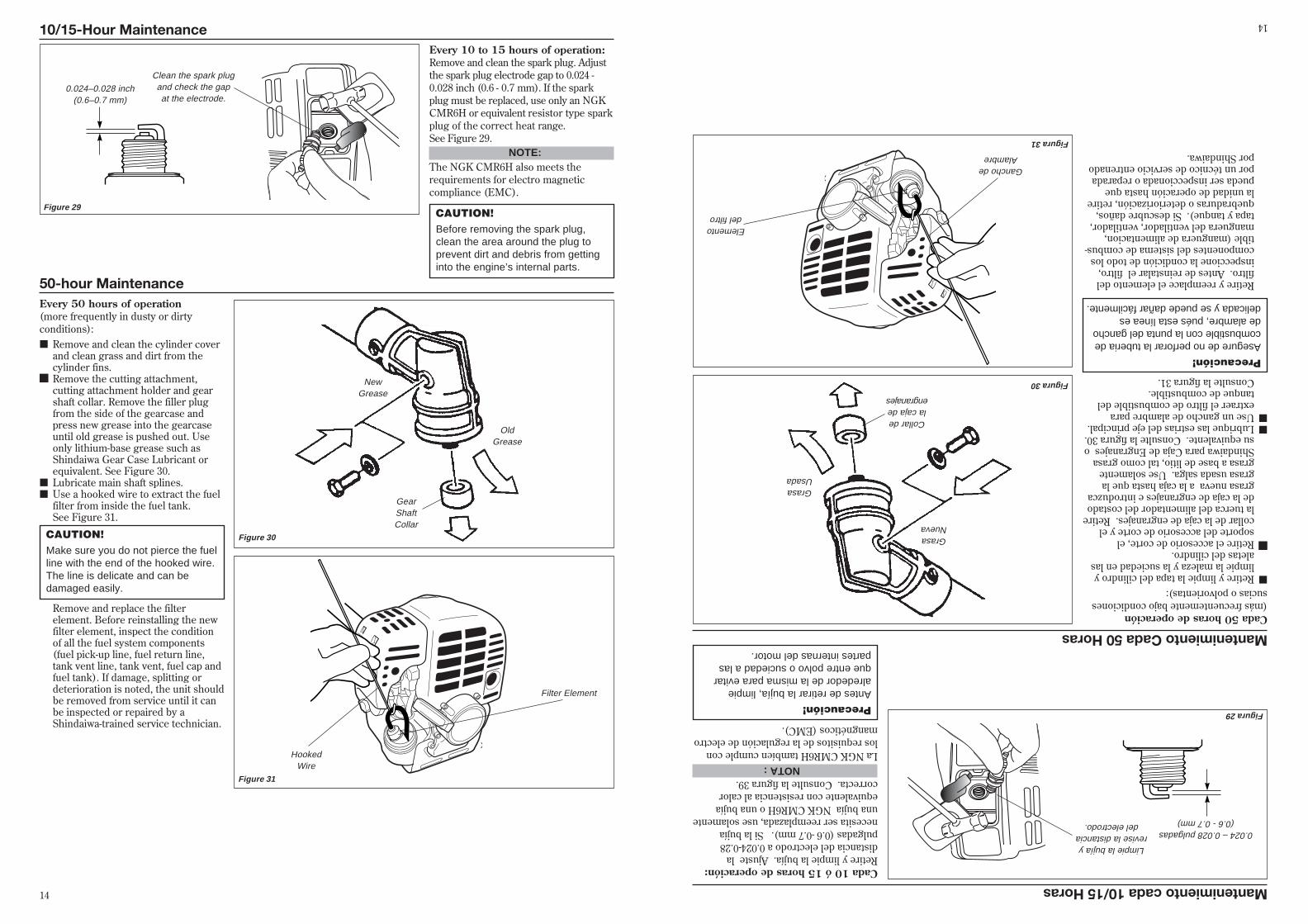
50-hour MaintenanceEvery 50 hours of operation(more frequently in dusty or dirtyconditions):■ Remove and clean the cylinder cover
and clean grass and dirt from thecylinder fins.
n Remove the cutting attachment,cutting attachment holder and gearshaft collar. Remove the filler plugfrom the side of the gearcase andpress new grease into the gearcaseuntil old grease is pushed out. Useonly lithium-base grease such asShindaiwa Gear Case Lubricant orequivalent. See Figure 30.
■ Lubricate main shaft splines.■ Use a hooked wire to extract the fuel
filter from inside the fuel tank.See Figure 31.
OldGrease
NewGrease
GearShaftCollar
Filter Element
HookedWire
Figure 30
Figure 31
CAUTION!Make sure you do not pierce the fuelline with the end of the hooked wire.The line is delicate and can bedamaged easily.
XST021
XST020A
Every 10 to 15 hours of operation:Remove and clean the spark plug. Adjustthe spark plug electrode gap to 0.024 -0.028 inch (0.6 - 0.7 mm). If the sparkplug must be replaced, use only an NGKCMR6H or equivalent resistor type sparkplug of the correct heat range.See Figure 29.
CAUTION!Before removing the spark plug,clean the area around the plug toprevent dirt and debris from gettinginto the engine’s internal parts.
Clean the spark plugand check the gapat the electrode.
10/15-Hour Maintenance
0.024–0.028 inch(0.6–0.7 mm)
Figure 29
NOTE:The NGK CMR6H also meets therequirements for electro magneticcompliance (EMC).
Remove and replace the filterelement. Before reinstalling the newfilter element, inspect the conditionof all the fuel system components(fuel pick-up line, fuel return line,tank vent line, tank vent, fuel cap andfuel tank). If damage, splitting ordeterioration is noted, the unit shouldbe removed from service until it canbe inspected or repaired by aShindaiwa-trained service technician.
14
XST022
XST021
XST020A
Mantenimiento Cada 50 HorasCada 50 horas de operación(más frecuentemente bajo condicionessucias o polvorientas):■Retire y limpie la tapa del cilindro y
limpie la maleza y la suciedad en lasaletas del cilindro.
nRetire el accesorio de corte, elsoporte del accesorio de corte y elcollar de la caja de engranajes. Retirela tuerca del alimentador del costadode la caja de engranajes e introduzcagrasa nueva a la caja hasta que lagrasa usada salga. Use solamentegrasa a base de litio, tal como grasaShindaiwa para Caja de Engranajes osu equivalente. Consulte la figura 30.
■Lubrique las estrias del eje principal.■Use un gancho de alambre para
extraer el filtro de combustible deltanque de combustible.Consulte la figura 31.
GrasaUsada
GrasaNueva
Collar dela caja deengranajes
Elementodel filtro
Gancho deAlambre
Figura 30
Figura 31
Precaución!Asegure de no perforar la tuberia decombustible con la punta del ganchode alambre, pués esta línea esdelicada y se puede dañar fácilmente.
Cada 10 ó 15 horas de operación:Retire y limpie la bujía. Ajuste ladistancia del electrodo a 0.024-0.28pulgadas (0.6 -0.7 mm). Si la bujíanecesita ser reemplazada, use solamenteuna bujía NGK CMR6H o una bujíaequivalente con resistencia al calorcorrecta. Consulte la figura 39.
Precaución!Antes de retirar la bujía, limpiealrededor de la misma para evitarque entre polvo o suciedad a laspartes internas del motor.
Limpie la bujía yrevise la distancia
del electrodo.
Mantenimiento cada 10/15 Horas
0.024 – 0.028 pulgadas(0.6 - 0.7 mm)
Figura 29
NOTA :La NGK CMR6H tambíen cumple conlos requisitos de la regulación de electromangnéticos (EMC).
Retire y reemplace el elemento delfiltro. Antes de reinstalar el filtro,inspeccione la condición de todo loscomponentes del sistema de combus-tible (manguera de alimentacion,manguera del ventilador, ventilador,tapa y tanque). Si descubre daños,quebraduras o deteriorización, retirela unidad de operación hasta quepueda ser inspeccionada o reparadapor un técnico de servicio entrenadopor Shindaiwa.
14
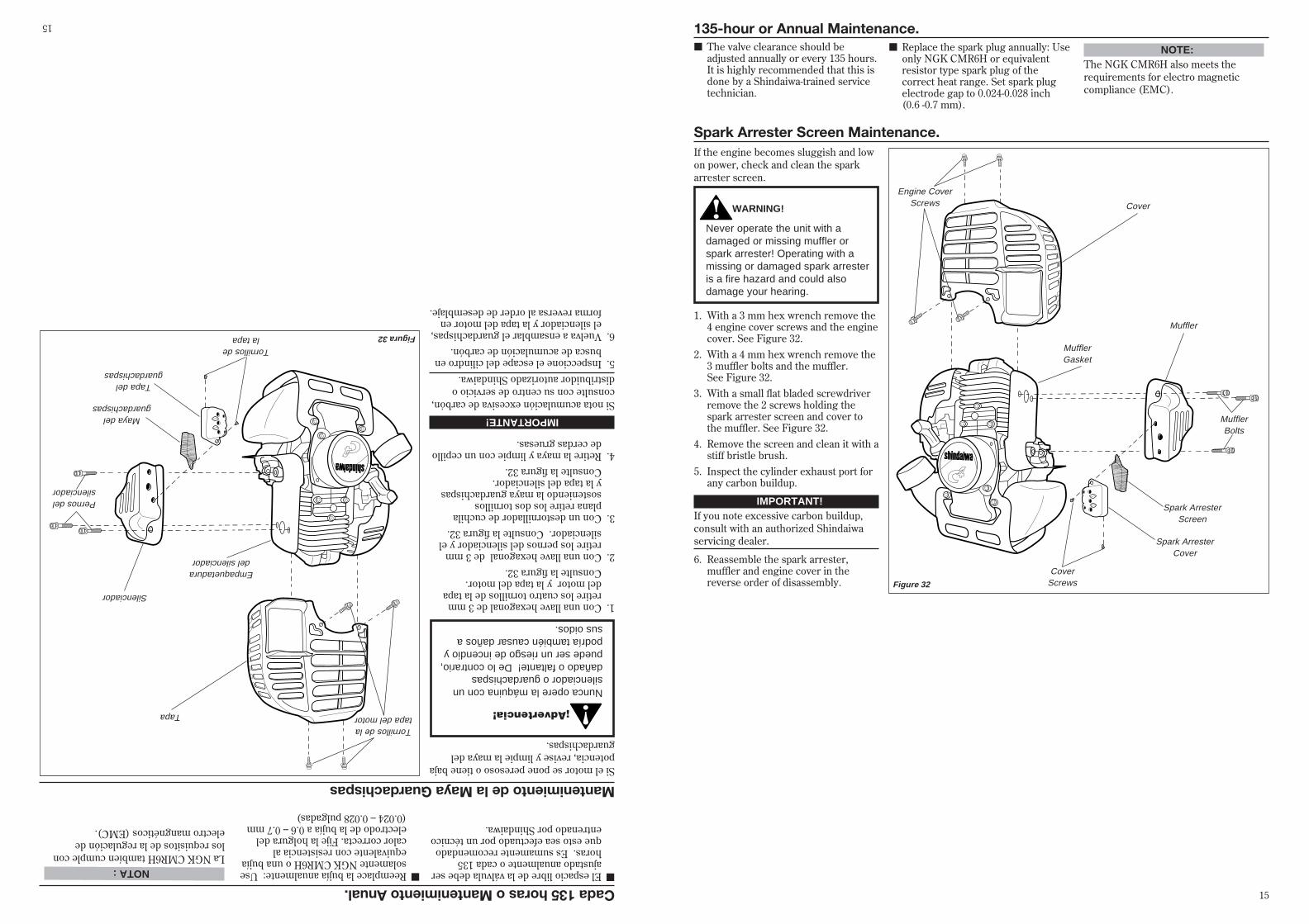
Spark Arrester Screen Maintenance.If the engine becomes sluggish and lowon power, check and clean the sparkarrester screen.
WARNING!
Never operate the unit with adamaged or missing muffler orspark arrester! Operating with amissing or damaged spark arresteris a fire hazard and could alsodamage your hearing.
1. With a 3 mm hex wrench remove the4 engine cover screws and the enginecover. See Figure 32.
2. With a 4 mm hex wrench remove the3 muffler bolts and the muffler.See Figure 32.
3. With a small flat bladed screwdriverremove the 2 screws holding thespark arrester screen and cover tothe muffler. See Figure 32.
4. Remove the screen and clean it with astiff bristle brush.
5. Inspect the cylinder exhaust port forany carbon buildup.
IMPORTANT!If you note excessive carbon buildup,consult with an authorized Shindaiwaservicing dealer.
6. Reassemble the spark arrester,muffler and engine cover in thereverse order of disassembly. Figure 32
MufflerBolts
Spark ArresterScreen
Cover
CoverScrews
MufflerGasket
Engine CoverScrews
Muffler
Spark ArresterCover
135-hour or Annual Maintenance.■ The valve clearance should be
adjusted annually or every 135 hours.It is highly recommended that this isdone by a Shindaiwa-trained servicetechnician.
■ Replace the spark plug annually: Useonly NGK CMR6H or equivalentresistor type spark plug of thecorrect heat range. Set spark plugelectrode gap to 0.024-0.028 inch(0.6 -0.7 mm).
NOTE:The NGK CMR6H also meets therequirements for electro magneticcompliance (EMC).
15
Mantenimiento de la Maya GuardachispasSi el motor se pone peresoso o tiene bajapotencia, revise y limpie la maya delguardachispas.
¡Advertencia!
Nunca opere la máquina con unsilenciador o guardachispasdañado o faltante! De lo contrario,puede ser un riesgo de incendio ypodría también causar daños asus oidos.
1.Con una llave hexagonal de 3 mmretire los cuatro tornillos de la tapadel motor y la tapa del motor.Consulte la figura 32.
2.Con una llave hexagonal de 3 mmretire los pernos del silenciador y elsilenciador. Consulte la figura 32.
3.Con un destornillador de cuchilaplana retire los dos tornillossosteniendo la maya guardachispasy la tapa del silenciador.Consulte la figura 32.
4.Retire la maya y limpie con un cepillode cerdas gruesas.
IMPORTANTE!
Si nota acumulación excesiva de carbón,consulte con su centro de servicio odistribuidor autorizado Shindaiwa.5.Inspeccione el escape del cilindro en
busca de acumulación de carbón.6.Vuelva a ensamblar el guardachispas,
el silenciador y la tapa del motor enforma reversa al order de desemblaje.
Figura 32
Pernos delsilenciador
Maya delguardachispas
Tapa
Tornillos dela tapa
Empaquetaduradel silenciador
Tornillos de latapa del motor
Silenciador
Tapa delguardachispas
Cada 135 horas o Mantenimiento Anual.■El espacio libre de la válvula debe ser
ajustado anualmente o cada 135horas. Es sumamente recomendadoque esto sea efectuado por un técnicoentrenado por Shindaiwa.
■Reemplace la bujía anualmente: Usesolamente NGK CMR6H o una bujíaequivalente con resistencia alcalor correcta. Fije la holgura delelectrodo de la bujía a 0.6 – 0.7 mm(0.024 – 0.028 pulgadas)
NOTA :La NGK CMR6H tambíen cumple conlos requisitos de la regulación deelectro mangnéticos (EMC).
15

Long Term Storage■ Remove the spark plug and pour
about 1/4 ounce of 2-cycle mixing oilinto the cylinder through the sparkplug hole. Slowly pull the recoilstarter 2 or 3 times so oil will evenlycoat the interior of the engine.Reinstall the spark plug.
■ Before storing the unit, repair orreplace any worn or damaged parts.
■ Remove the air cleaner element fromthe carburetor and clean it thor-oughly with soap and water. Let dryand reassemble the element.
■ Store the unit in a clean,dust-free area.
Whenever the unit will not be used for30 days or longer, use the followingprocedures to prepare it for storage:■ Clean external parts thoroughly.■ Drain all the fuel from the fuel tank.
IMPORTANT!
All stored fuels should be stabilizedwith a fuel stabilizer such as STA-BIL™ ,if oil with fuel stabilizer isnot used.
1. Prime the primer bulb until no morefuel is passing through.
2. Start and run the engine until itstops running.
3. Repeat steps 1 and 2 until the enginewill no longer start.
CAUTION!Gasoline stored in the carburetorfor extended periods can causehard starting and could also leadto increased service and mainte-nance cost.
Blade SharpeningWhen the cutting edges of the bladebecome dull, they can be resharpenedwith a few strokes of a file.In order to keep the blade in balance,all cutting edges must besharpened equally.
Shindaiwa Tornado� BladeTo sharpen the cutters on a ShindaiwaTornado Blade, use a 7/32-inch roundfile. File the leading edge of each toothto a razor edge. The top plate of eachtooth should angle back 30° .
WARNING!Sharpen only the cutting
teeth of a blade. DO NOT alter thecontour of the blade in any way.
Multiple-tooth Circular BladeUse a round file to maintain a radius of0.04 to 0.06" (1 to 1.5 mm) at the base ofeach tooth. Cutting edges must be offsetequally on each side.
RoundFile
30°
RoundFile
Figure 34
Figure 33
■ Remove the remaining fuel from thefuel lines and carburetor.
16
Almacenamiento de Largo Plazo■Retire la bujía y vierta
aproximadamente 1/4 de onza deaceite de mezcla para motores de 2tiempos en el cilindro a través delagujero de la bujía . Lentamente jaleel arrancador 2 ó 3 veces para que elaceite se aplique uniformemente enel interior del motor. Reínstalela bujía.
■Antes de almacenar la máquina,repare o cambie cualquier piezadañada o gastada.
■Retire el elemento del filtro de aire ylimpielo minuciosamente con agua yjabón. Deje que seque y vuelva aensamblar el elemento.
■Almacene la máquina en un sitiolimpio y libre de polvo.
Cada vez que la máquina no va a serusada por 30 días o más, siga lossiguientes procedimientos para prepararsu almacenamiento:
■Limpie las partes externas y apliqueuna capa ligera de aceite a todas lassuperficies metálicas.
■Drene todo combustible en el tanque.
IMPORTANTE!
Todo combustible almacenado debeestar estabilizado con un estabilizadorde combustible tal como STA-BIL, almenos que use aceite conestabilizador de combustible.
1.Empuje la bombilla de cebado hastaque el combustible deje de pasar.
2.Arranque y mantenga prendido elmotor hasta que pare de funcionar.
3.Repita los pasos 1 y 2 hasta que elmotor ya no arranque.
Precaución!Gasolina almacenada en elcarburador por periódos largospuede causar un arranque duro ypuede conducir a un aumento encosto de servicio y mantenimiento.
Afilado de DiscosCuando los bordes de la cuchillapierdan su filo, pueden ser afiladosrápidamente con una lima. Paramantener la cuchilla balanceada, todoslos bordes deben ser afiladosuniformemente.
Disco Shindaiwa Tornado�
Para afilar los dientes de corte de undisco shindaiwa Tornado ™, use unalima redonda de 7/32 pulgadas. Afileel borde líder de cada diente hastaobtener un filo similar al de una hojade afeitar. La superficie superior decada diente debe tener una inclinaciónde 30 grados. Consulte la figura 33.
¡Advertencia!
Afile solamente los dientes decortar. NO altere de ninguna formael contorno del disco.
Discos de Dientes MúltiplesUse una lima redonda para mantenerun radio de 0.04 a 0.06 pulgadas(1 a 1.5mm) en la base de cada diente.Los dientes deben quedar igualmentedescentrados por cada lado.Consulte la figura 34.
Limaredonda
30 grados
Limaredonda
Figura 34
Figura 33
■Retire el resto del combustible en lastuberias de combustible ycarburador.
16

Troubleshooting GuideENGINE DOES NOT START
Does the engine crank?Faulty recoil starter.Fluid in the crankcase.Internal damage.
Consult with an authorized servicing dealer.Consult with an authorized servicing dealer.Consult with an authorized servicing dealer.
Consult with an authorized servicing dealer.Consult with an authorized servicing dealer.
Consult with an authorized servicing dealer.Consult with an authorized servicing dealer.
NO
Good compression?Loose spark plug.Excess wear on cylinder, piston, rings.Valves not seating.
Tighten and re-test.NO
YES
Does the tank contain fresh fuel of the proper grade?
Refill with fresh, clean unleaded gasoline with a pump octane of 87 or higher mixed with a 2-cycle air cooled mixing oil that meets or exceeds ISO-L-EGD and/or JASO FC classified oils at 50:1 gasoline/oil ratio.
Fuel incorrect, stale or contaminated; mixture incorrect.NO
YES
Is fuel visible and moving in the return line when priming?
Check for clogged fuel filter and/or vent.
Priming pump not functioning properly.
Replace fuel filter or vent as required; restart.
Consult with an authorized servicing dealer.
NO
Is there spark at the spark plug wire terminal?
The ignition switch is in “O” (OFF) position.Shorted ignition ground.Faulty ignition unit.
Move switch to “I” (ON) position and restart.NO
YES
YES
Check the spark plug.If the plug is wet, excess fuel may be in the cylinder.
The plug is fouled or improperly gapped.
The plug is damaged internally or of thewrong size.
Crank the engine with the plug removed, reinstall the plug, and restart.
Clean and regap the plug to 0.024 - 0.028 inch (0.6 - 0.7 mm). Restart.
Replace the plug with an NGK CMR6H or equivalent resistor type spark plug of the correct heat range. Set spark plug electrode gap to 0.024-0.028 inch (0.6-0.7 mm).
YES
What To Check Possible Cause Remedy
Is the engine overheating?Operator is overworking the unit.
Carburetor mixture is too lean.
Improper fuel ratio.
Fan, fan cover, cylinder fins dirty or damaged.
Carbon deposits on the piston or in the muffler.
Shorten trimmer line. Cut at a slower rate.
Consult with an authorized servicing dealer.
Refill with fresh, clean unleaded gasoline with a pump octane of 87 or higher mixed with a 2-cycle air cooled mixing oil that meets or exceeds ISO-L-EGD and/or JASO FC classified oils at 50:1 gasoline/oil ratio.
Clean, repair or replace as necessary.
Consult with an authorized servicing dealer.
What To Check Possible Cause Remedy
Engine is rough at all speeds. May also haveblack smoke and/or unburned fuel at theexhaust.
Clogged air cleaner element.
Loose or damaged spark plug.
Air leakage or clogged fuel line.
Water in the fuel.
Piston seizure.
Faulty carburetor and/or diaphragm.
Valve clearance set incorrectly.
Service the air cleaner element.
Tighten or replace.
Repair or replace filter and/or fuel line.
Replace the fuel. See page 9.
Consult with an authorized servicing dealer.
Consult with an authorized servicing dealer.
Consult with an authorized servicing dealer.
Engine is knocking. Overheating condition.
Improper fuel.
Carbon deposits in the combustion chamber.
Valve clearance set incorrectly.
See above.
Check fuel octane rating; check for presence ofalcohol in the fuel (pg. 9). Refuel as necessary.
Consult with an authorized servicing dealer.
Consult with an authorized servicing dealer.
LOW POWER OUTPUT
17
Guia DiagnosticoEL MOTOR NO ARRANCA
BAJA POTENCIA
¿Arranca el motor?Arrancador defectuoso. Liquido en el cárter. Daños internos.
Consulte con su agente de servicio autorizado.
Consulte con su agente de servicio autorizado.
Consulte con su agente de servicio autorizado.
NO
¿Buena compresión?Bujía floja. Desgaste en el cilindro, pistón, anillos. Las válvulas no están asentadas.
Ajuste y pruebe otra vez.NO
SI
¿Contiene el tanque combustible fresco y del octanaje correcto?
Vuelva a llenar con combustible fresco, limpio y sin plomo con un octanaje de 87 o superior mezclado con aceite de mezcla para motores de 2 tiempos Shindaiwa enfriado por aire que cumple o excede los aceites clasificados ISO-L-EGD y/o JASO FC a una proporción de 50:1 de gasolina/aceite.
Combustible incorrecto, viejo, o contaminado; mezcla incorrecta. NO
SI
¿Se ve el combustible circular por la línea de retorno al realizar el cebado?
Revise el filtro y/o el ventilador en busca de obstrucción.Bomba de Cebado no funciona propiamente.
Reemplace el filtro de combustible o la valvula de presion cuando sea necesario; vuelva a encender.Consulte con su agente de servicio autorizado.
NO
¿Hay chispa en el terminal del cable de bujía?
El interruptor de encendido está en posición “O” (OFF) (apagado). Corta conexión a tierra. Sistema de encendido o ignición defectuoso.
Mueva el interruptor a la posición de encendido (I) y vuelva arrancar. NO
SI
SI
Revise la bujía.Si la bujía está húmeda, puede haber exceso de combustible en el cilindro. La bujía está obstruída o tiene la holgura incorrecta.
La bujía está dañada internamente o es el tamaño equivocado.
Retire la bujía y arranque el motor; reinstale la bujía y vuelva arrancar.
Limpie y calibre la bujía a 0.024 – 0.028 pulgadas (0.6 – 0.7mm). Vuelva arrancar.
Cambie la bujía por una NGK CMR6H o una equivalente con resistencia al calor correcta. Fije la holgura del electrodo de la bujía a 0.024 – 0.028 pulgadas (0.6 – 0.7 mm).
SI
Que RevisarPosible CausaRemedio
¿Se está sobrecalentando el motor?
El operador esta sobre trabajando la máquina.La mezcla del carburador es muy pobre.
Proporción de combustible inapropiada.
Ventilador, tapa del ventilador, aletas del cilindro están sucios o dañados.Depósitos de carbón en el pistón o en el silenciador.
Recorte la línea recortadora. Corte más despacio.
Consulte con su agente de servicio autorizado.
Vuelva a llenar con combustible fresco, limpio y sin plomo con un octanaje de 87 o superior mezclado con aceite de mezcla para motores de 2 tiempos Shindaiwa enfriado por aire que cumple o excede los aceites clasificados ISO-L-EGD y/o JASO FC a una proporción de 50:1 de gasolina/aceite.
Limpie, repare o cambie si es necesario.
Consulte con su agente de servicio autorizado.
Que RevisarPosible CausaRemedio
El motor funciona bruscamente en cualquier velocidad. Puede tener humo negro y/o combustible sin usar en el escape.
Filtro de aire obstruído.
Bujía floja o dañada.
Fuga de aire o línea de combustible obstruída.Agua en el combustible.
Pistón trabado.
Carburador defectuoso y/o diafragma.
Limpie el elemento del filtro de aire.
Apriete o cámbiela. Cambie la bujía por NGK BMR6A.
Repare o cambie el filtro y/o la manguera de combustible.
Cambie el combustible. Consulte la pagina 9.
Consulte con su agente de servicio autorizado.
Consulte con su agente de servicio autorizado.
El motor está pateando.Sobrecalentamiento
Combustible inadecuado
Depósitos de carbón en la cámara de combustión.
Consulte arriba.
Revise el índice de octanaje del combustible. Revise si hay alcohol en el combustible. (página 7). Vuelva a llenar si es necesario.
Consulte con su agente de servicio autorizado.
17
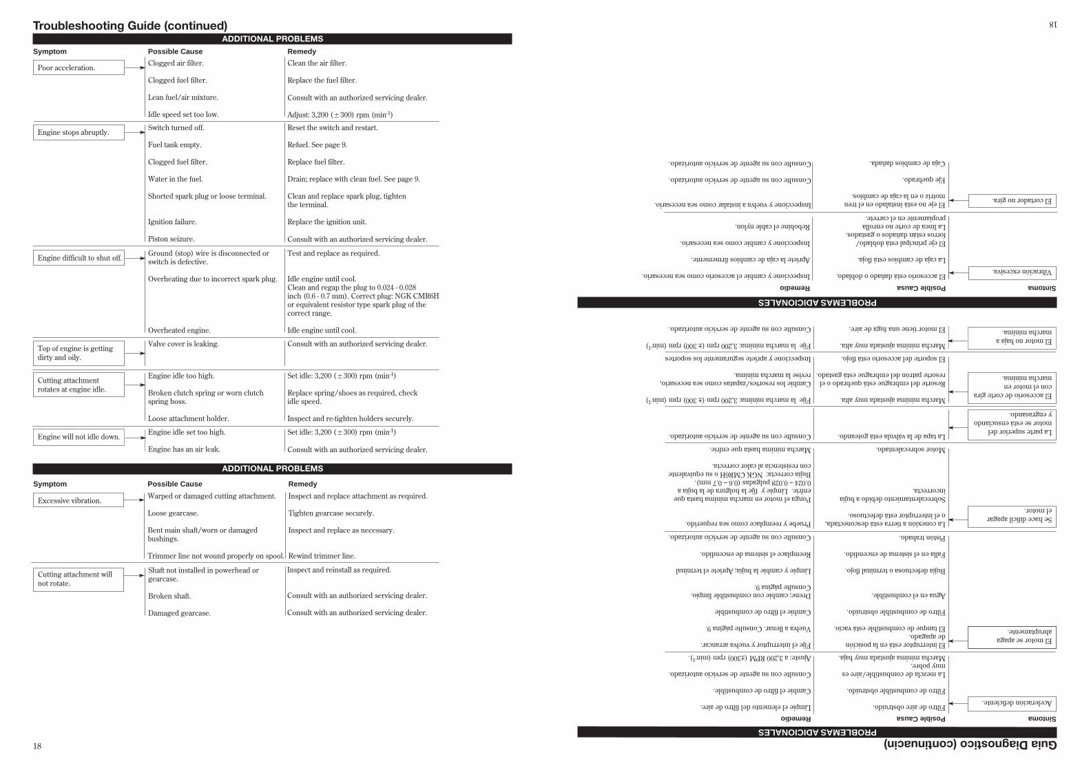
Troubleshooting Guide (continued)ADDITIONAL PROBLEMS
Poor acceleration.Clogged air filter.
Clogged fuel filter.
Lean fuel/air mixture.
Idle speed set too low.
Clean the air filter.
Replace the fuel filter.
Consult with an authorized servicing dealer.
Adjust: 3,200 (�300) rpm (min-1)
Symptom Possible Cause Remedy
Engine stops abruptly.Switch turned off.
Fuel tank empty.
Clogged fuel filter.
Water in the fuel.
Shorted spark plug or loose terminal.
Ignition failure.
Piston seizure.
Reset the switch and restart.
Refuel. See page 9.
Replace fuel filter.
Drain; replace with clean fuel. See page 9.
Clean and replace spark plug, tighten the terminal.
Replace the ignition unit.
Consult with an authorized servicing dealer.
Engine difficult to shut off.Ground (stop) wire is disconnected or switch is defective.
Overheating due to incorrect spark plug.
Overheated engine.
Test and replace as required.
Idle engine until cool.Clean and regap the plug to 0.024 - 0.028 inch (0.6 - 0.7 mm). Correct plug: NGK CMR6H or equivalent resistor type spark plug of the correct range.
Idle engine until cool.
Cutting attachment rotates at engine idle.
Engine idle too high.
Broken clutch spring or worn clutch spring boss.
Loose attachment holder.
Set idle: 3,200 (�300) rpm (min-1)
Replace spring/shoes as required, check idle speed.
Inspect and re-tighten holders securely.
Engine will not idle down.Engine idle set too high.
Engine has an air leak.
Set idle: 3,200 (�300) rpm (min-1)
Consult with an authorized servicing dealer.
Top of engine is getting dirty and oily.
Valve cover is leaking. Consult with an authorized servicing dealer.
ADDITIONAL PROBLEMS
Symptom Possible Cause Remedy
Excessive vibration.Warped or damaged cutting attachment.
Loose gearcase.
Bent main shaft/worn or damaged bushings.
Trimmer line not wound properly on spool.
Inspect and replace attachment as required.
Tighten gearcase securely.
Inspect and replace as necessary.
Rewind trimmer line.
Cutting attachment will not rotate.
Shaft not installed in powerhead or gearcase.
Broken shaft.
Damaged gearcase.
Inspect and reinstall as required.
Consult with an authorized servicing dealer.
Consult with an authorized servicing dealer.
18
Guia Diagnostico (continuacin)PROBLEMAS ADICIONALES
PROBLEMAS ADICIONALES
Aceleración deficiente.Filtro de aire obstruído.
Filtro de combustible obstruído.
La mezcla de combustible/aire es muy pobre.Marcha mínima ajustada muy baja.
Limpie el elemento del filtro de aire.
Cambie el filtro de combustible.
Consulte con su agente de servicio autorizado.
Ajuste: a 3,200 RPM (±300) rpm (min-1).
SíntomaPosible CausaRemedio
El motor se apaga abruptamente.
El interruptor está en la posición de apagado.El tanque de combustible está vacío.
Filtro de combustible obstruído.
Agua en el combustible.
Bujía defectuosa o terminal flojo.
Falla en el sistema de encendido.
Pistón trabado.
Fije el interruptor y vuelva arrancar.
Vuelva a llenar. Consulte página 9.
Cambie el filtro de combustible
Drene; cambie con combustible limpio. Consulte página 9.
Limpie y cambie la bujía; Apriete el terminal
Reemplace el sistema de encendido.
Consulte con su agente de servicio autorizado.
Se hace difícil apagar el motor.
La conexión a tierra está desconectada, o el interruptor está defectuoso.
Sobrecalentamiento debido a bujía incorrecta.
Motor sobrecalentado.
Pruebe y reemplace como sea requerido.
Ponga el motor en marcha mínima hasta que enfríe. Limpie y fije la holgura de la bujía a 0.024 – 0.028 pulgadas (0.6 – 0.7 mm). Bujía correcta: NGK CMR6H o su equivalente con resistencia al calor correcta.
Marcha mínima hasta que enfríe.
El accesorio de corte giracon el motor en marcha mínima.
Marcha mínima ajustada muy alta.
Resorte del embrague está quebrado o el resorte patrón del embrague está gastado.
El soporte del accesorio está flojo.
Fije la marcha mínima: 3,200 rpm (± 300) rpm (min-1)
Cambie los resortes/zapatas como sea necesario, revise la marcha mínima.
Inspeccione y apriete seguramente los soportes
El motor no baja a marcha mínima.
Marcha mínima ajustada muy alta.
El motor tiene una fuga de aire.
Fije la marcha mínima: 3,200 rpm (± 300) rpm (min-1)
Consulte con su agente de servicio autorizado.
La parte superior del motor se está ensuciando y engrasando.
La tapa de la válvula está goteando.Consulte con su agente de servicio autorizado.
SintomaPosible CausaRemedio
Vibración excesiva.El accesorio está dañado o doblado.
La caja de cambios está floja.
El eje principal está doblado/ forros están dañados o gastados.La línea de corte no enrolla propiamente en el carrete.
Inspeccione y cambie el accesorio como sea necesario.
Apriete la caja de cambios firmemente.
Inspeccione y cambie como sea necesario.
Rebobine el cable nylon.
El cortador no gira.El eje no está instalado en el tren motríz o en la caja de cambios.
Eje quebrado.
Caja de cambios dañada.
Inspeccione y vuelva a instalar como sea necesario.
Consulte con su agente de servicio autorizado.
Consulte con su agente de servicio autorizado.
18
Your Warranty Rights andObligations
The California Air Resources Board, the U.S. EnvironmentalProtection Agency and Shindaiwa Kogyo Co., Ltd. are pleasedto explain the emission control system warranty on your newsmall off-road (non-road) engine.
In California, new small off-road engines must be de-signed, built, and equipped to meet the State’s stringent anti-smog standards. In other states, new 1997 and later non-road engines must meet the Federal EPA’s stringent anti-smog standards. Shindaiwa Kogyo Co., Ltd. must warrantthe emission control system on your small off-road enginefor the periods of time listed below, provided there has beenno abuse, neglect, or improper maintenance of your smalloff-road engine.
Your engine emission control system includes parts suchas the carburetor, the ignition system and, if equipped, thecatalytic converter. These components are specifically listedbelow.
Where a warrantable condition exists, Shindaiwa KogyoCo., Ltd. will repair your small off-road engine at no cost toyou including diagnosis, parts, and labor.
Manufacturer’s WarrantyCoverage
When sold within the U.S., this engine’s emission controlsystem is warranted for a period of two (2) years from thedate this product is first delivered to the original retailpurchaser.
During the warranty period, Shindaiwa Kogyo Co., Ltd.will, at their option, repair or replace any defective emission-related component on this engine. During the originalWarranty Period, these Warranty Rights are automaticallytransferable to subsequent owners of this product.
What is Covered by thisWarranty1. Carburetor Internal Components
■ Throttle Valve, Needle, Jet, Metering Diaphragm
2. Ignition System Components■ Ignition Coil■ Flywheel Rotor
3. Catalytic Converter (if originally equipped)The emission control system for your particular
Shindaiwa engine may also include certain related hosesand connectors.
Emission System Warranty StatementOwners WarrantyResponsibilities
As the small off-road engine owner, you are responsiblefor the performance of the required maintenance listed inthis owners manual. Shindaiwa Kogyo Co., Ltd. recom-mends that you retain all receipts covering maintenance onyour small off-road engine, but Shindaiwa Kogyo Co., Ltd.cannot deny warranty solely for the lack of receipts or foryour failure to ensure the performance of all scheduledmaintenance.
As the small off-road engine owner, you should be aware,however, that Shindaiwa Kogyo Co., Ltd. may deny youwarranty coverage if your small off-road engine or a part hasfailed due to abuse, neglect, improper maintenance, orunapproved modifications.
You are responsible for presenting your small off-roadengine to an authorized Shindaiwa Dealer as soon as aproblem exists. The warranty repairs should be completedin a reasonable amount of time, not to exceed 30 days.
If you have any questions regarding your warranty rightsand responsibilities, you should contact a Shindaiwacustomer service representative at (503) 692-3070 or yourlocal Shindaiwa Dealer.
Consequential DamagesIn the event that other component parts of this product
are damaged by the failure of a warranted part, ShindaiwaKogyo Co., Ltd. will repair or replace such component partsat no charge to you.
What is Not Covered■ Failures caused by abuse, neglect, or improper
maintenance procedures.■ Failures caused by the use of modified or non-approved
parts or attachments.
This Warranty is Administered by:
Shindaiwa Inc.11975 S.W. Herman Rd.Tualatin, OR 97062(503) 692-3070
19
Sus Derechos y Obligaciones de GarantíaLa Junta de Recursos de Aire de California, La Agencia de
Protección del Ambiente Estadounidense y ShindaiwaKogyo Co., Ltd se complacen en explicar la guarantía delsistema de control de emisión de su nuevo motor pequeño(no para el uso en automóviles).
En California, los motores pequeños (no para el uso enautomóviles) están diseñados, construídos y equipados paracumplir con las normas exigentes de anti-smog del Estadode California. En otros estados, los motores nuevos (no parael uso en automóviles) de 1997 para adelante deben cumplirlas normas federales exigentes de la EPA de anti-smog.Shindaiwa Kogyo Co., Ltd debe garantizar el sistema decontrol de emisión de su motor pequeño (no para el uso enautomóviles) durante los periódos mencionados abajo,asumiendo que no haya habido abuso, negligencia omantenimiento impropio en su motor pequeño (no para eluso en automóviles).
Su sistema de control de emisión incluye partes, tal comoel carburador, el sistema de encendido, y, si equipado,convertidor catalítico. Estos componentes estánmencionados especificamente abajo.
Cuando exista una condición bajo garantía , ShindaiwaKogyo Co., Ltd reparará su pequeño motor (no para el usoen automóviles) sin costo alguno para usted incluyendo eldiagnóstico, repuestos y mano de obra.
Cobertura de la Garantía del FabricanteCuando vendido dentro de los Estados Unidos, el sistema
de control de emisión de este motor está garantizado por unperiódo de dos (2) años desde la fecha en que el producto esentregado por primera vez al comprador minorista original .
Durante el periódo de la garantía, Shindaiwa Kogyo Co.,Ltd reparará o cambiará, a su discreción, cualquiercomponente defectuoso relacionado con el sistema deemisión del motor. Durante el periódo original de lagarantía, estos derechos de garantía son automáticamentetransferibles a propietarios subsiguientes de este producto.
Que Está Cubierto Por Esta Garantía1.Los componentes internos del carburador.
■ La válvula de aceleración, la aguja, pitón, Diafragma Medidor.
2.Los componentes del sistema de encendido.■ Rosca del arrancador.■ Rotor del volante.
3.Convertidor catalítico (si está originalmente equipado).El sistema de control de emisión de su motor Shindaiwa
puede también incluir ciertas mangueras y conexionesparticulares.
Declaración de Garantía delSistema de EmisiónResponsabilidades de Garantía del Propietario
Como propietario del motor pequeño (no para el uso enautomóviles), es usted responsable por el rendimiento delmantenimiento requerido y mencionado en este manual delpropietario. Shindaiwa Kogyo Co., Ltd recomienda queguarde todo los recibos que prueben el mantenimiento desu motor pequeño (no para el uso en automóviles), peroShindaiwa Kogyo Co., Ltd no puede negar la garantíasolamente por la falta de recibos o por no llevar a cabo losmantenimientos programados.
Como propietario del motor pequeño (no para el uso enautomóviles), debe saber que Shindaiwa Kogyo Co., Ltdpuede negarle la cobertura de garantía si su motor o suspartes han fallado debido a abuso, negligencia,mantenimiento impropio, o modificaciones no autorizadas.
Usted es responsable de presentar su pequeño motor (nopara el uso en automóviles) a un centro de servicioShindaiwa autorizado tan pronto como se presente unproblema. Las reparaciones bajo garantía deben sercompletadas en un tiempo razonable que no excedade 30 días.
Si tiene alguna pregunta con respecto a sus derechos yresponsabilidades de garantía, usted debe contactar a unrepresentante del servicio al cliente de Shindaiwa al (503)692-3070 o a su centro local de servicio Shindaiwa.
Daños ConsiguientesEn el evento de que alguna otra parte de los
componentes de este producto estén dañadas debido a lafalla de alguna parte bajo la garantía, Shindaiwa Kogyo Co.,Ltd, reparará o cambiará tales partes sin costo algunopara usted.
Que No Est Cubierto■Fallas causadas por abuso, negligencia, o
mantenimiento impropio.■Fallas causadas por el uso de piezas o accesorios
modificados o no autorizados.
Esta garantía es administrada por:Shindaiwa Inc.11975 SW Herman RdTualatin, OR 97062Telefono: 503 692 3070
19

NOTES
20
NOTAS
20