Embed Size (px)
Citation preview

Saab TransponderTech
OPERATOR’S MANUALR4 Navigation System

CopyrightThe entire contents of this manual and its appendices, including any future updates and modifications, shall remain the property of Saab TransponderTech AB at all times. The contents must not, whether in its original form or modified, be wholly or partly copied or reproduced, nor used for any other purpose than the subject of this manual.
DisclaimerWhile reasonable care has been exercised in the preparation of this manual, Saab TransponderTech AB shall incur no liability whatsoever based on the contents or lack of contents in the manual.
CautionNo single navigation aid should ever be relied upon as the exclusive means for navigating a vessel. The navigator is responsible for checking all aids available to confirm his posi-tion. Electronic aids are intended to assist, not replace, the navigator.
SoftwareThis manual reflects the capabilities of R4 Navigation Display software version 5.0.90 onwards.
Operators Manual Part Number and RevisionPart number 7000 109-143, revision F2.This manual is a replacement for the earlier manual 7000 109-143 rev F.
Safety InstructionsNote the following compass safe distances:
How To Contact Us
For Information on New Products and Dealers:Please visit our home page www.transpondertech.se
For Installation, Service and Technical Support:Please contact your R4 Navigation System dealer.
Equipment Standard magnetic compass
Steering magnetic compass
R4 Display 0.6 m 0.3 m
R4 Navigation Sensor (GPS and DGPS)
0.6 m 0.4 m

3
Ta
ble
of C
on
ten
ts
Table of Contents
Product Description ................................................. 7System Overview 7Main Features 8
Concepts and Terminology ..................................... 9
Getting Started ...................................................... 11Front Panel Keys 11
How to Operate the R4 Display 12Views and Function Keys 12Change Settings 12Alarm Pop-ups 13Turning On and Off the R4 Display 13
System Modes 14Status Bar 16
Status Icons 16RAIM Accuracy Level 17
Show Current Position 18Create Waypoints 18Create New Waypoint 19
Sail To a Waypoint 20Create a Route 22
Insert Waypoints Into the Route 23Adjusting Navigation Algorithm and RAIM Accuracy Level 25Finish Creating a Route 26
Review an Existing Route 27Start Sailing a Route 29
Navigate Towards a Waypoint and Follow a Route 30Plot the Active Route 31View the Active Route 32Visual Settings 33
Reference .............................................................. 35Status LEDs 35
R4 Display LEDs 35R4 Navigation Sensor LEDs 35
Icon Description 36Message Symbols 36Redundant Operation Status Symbols 36GPS Status Symbols 36Miscellaneous Symbols 36

4
Adjusting Settings 37Man Over Board 39Event Mark 40Alarm Pop-ups 41Changing System Mode 42Navigate Mode 43
Overview 43Position 45
GPS Status 46Beacon Status 47Satellite Info 48SBAS Info 48Set RAIM 49
Nav 50Active Route 53
Edit Active Route 56Plot 59User Defined 60Trip Logs 63
Trip Log Details 64Anchor Watch 65Route List 67
Plan Voyage Mode 69Overview 69Route List 71
Sail Route 73Sail To 73Edit Route 75Create Route 78Create Route From 79View Route 79
Route Related Views 81Select Waypoint 81Insert Waypoints 82Select Route 83
Waypoint List 85Waypoint Related Views 88
View Waypoint 88Edit Waypoint 88Create Waypoint 90
Alarms & Msgs Mode 91Overview 91Alarm List 92DGPS Message 93Scheduled Alerts 93Scheduled Alert Related Views 94
Create Time Alert 95Create ETA Alert 96Edit Time Alert 97Edit ETA Alert 97

5
Ta
ble
of C
on
ten
ts
View Time Alert 97View ETA Alert 97
Config Mode 99Overview 99Time Config 101Display Config 102
Visual Config 102Sound Config 103
Nav Config 103Alarm Config 105Units Config 106GPS/DGPS Config 107
GPS Config 107Beacon Config 109SBAS Config 111
Redund Config 112I/O Config 114
Input Config 114Compass Config 115Depth Config 115Wp/Rte Input 116Output Config 117
Port Rate Config 118System Info 121
Appendix .............................................................. 123Alarm Messages 123
Navigation Alarms Description 123Transfer Waypoints and Routes 126
Download Waypoints and Routes 126Waypoint and Complete Route Downloads 126Working Route Downloads 126
Upload Waypoints and Complete Routes 126Output Working Route and Remaining Waypoints 127
Glossary ............................................................... 129
Index .................................................................... 131

6

7
Pro
du
ct D
es
crip
tion
System Overview
Product Description
System Overview
The R4 Navigation System is available in two configurations: GPS and DGPS. Both con-figurations feature an R4 Display. The GPS configuration also features an R4 GPS Nav-igation Sensor and an MGA-2 GPS antenna, while the DGPS configuration features an R4 DGPS Navigation Sensor and an MGL-4 combined GPS/Beacon antenna.
The R4 Display provides a graphical interface to the system. Via the display it is possible to create, edit and modify routes and waypoints, navigate following a route, plot the route, view sensor data, perform setup as well as supervise the systems status.
The R4 GPS Navigation Sensor features a high-precision GPS receiver, capable of receiv-ing WAAS, EGNOS and MSAS differential corrections. The R4 DGPS Navigation Sen-sor has all the features of the GPS Sensor, as well as a dual channel beacon receiver for reception of IALA radio beacon DGPS corrections.
The R4 Navigation Sensor is connected to the antenna, either an MGA-2 GPS antenna or an MGL-4 combined GPS/Beacon antenna. The MGL-4 antenna is capable of receiving and interpreting both radio beacon and satellite signals.
Together the R4 Display and the R4 Navigation Sensor provides three configurable serial user ports, of which two are bidirectional and one used only for output of data. There are also a binary Speed Log and an Alarm Output port, as well as an Alarm Acknowledge in-put port.
Main Features
8
Main Features
• High resolution, sunlight readable, 6'' graphic day and night display.• Signal integrity monitoring calculations (RAIM) according to the IEC 61108-1 (2nd
edition) standard. The RAIM function detects whether an expected user defined navi-gation accuracy is achieved.
• Reception and use of differential corrections from SBAS, from the serial interface in RTCM SC-104 format and, in the DGPS configuration, from IALA radio beacons.
• Automatic or manual SBAS satellite selection modes. • Navigational views with next waypoint information and cross-track error visualiza-
tion.• Display of latitude, longitude, speed over ground and course over ground.• Up to five user defined views providing a large variety of graphical as well as numer-
ical presentation options according to customer preferences.• Capability to handle and store up to 2000 individually named waypoints and up to 100
different routes.• Man Over Board (MOB) and Event Mark functionality.• Two trip log counters with indication of average speed and accumulated time during
motion.• Anchor Watch position deviation alarm.• Scheduled Alerts, user configurable time alarms and time to ETA alarms.• Time frame related to UTC or user defined local offset.• Synchronization of waypoint/route database and settings with an external R4 Naviga-
tion system in dual redundant installations. • Input and output of IEC 61162-1 sentences configurable on sentence level and per
port, providing control over interpreted, ignored and transmitted sentences.• User interface design centred around modes of operation corresponding to typical
operator activities such as voyage planning, status monitoring and ship navigation.• Upgradeable without hardware modifications due to fully integrated DSP solution.• Output of GPS positioning information on User port 1 and 2, enabling external sys-
tems to connect to and use the GPS information from the R4 Navigation Sensor.• Meets the following standards:
• IMO Performance Standard for GPS• IEC 61108-1, second edition• IEC 61162-1, second edition

9
Co
nc
ep
ts a
nd
Te
rmin
olo
gy
Concepts and Terminology
This chapter describes some of the commonly used terms of this Operator’s Manual, and the implied meaning when used in this manual.
WaypointA waypoint is a position on the earths surface, represented by latitude and longitude, which is given a unique name. A waypoint is typically used for navigation direct to a cer-tain position or as part of a route.
MOB WaypointA waypoint created when using the Man Over Board (MOB) functionality. The system can store up to 20 MOB waypoints at the same time, if more are created the oldest one is deleted. It is not possible to use MOB waypoints in routes.
RouteA route is a named, ordered sequence of waypoints, which together describes a path from the start to the end waypoint. The route that currently is being sailed is called the active route.
Active RouteThe active route is the route currently being sailed and used for navigation. When starting to sail a route, a copy of the route is made into the active route. Changes made to the active route does not affect the source route, unless the active route is explicitly stored. Only one route can be active at any point in time.
LegA leg is the segment of a route between two consecutive waypoints. A route with the way-points A, B and C has two legs: “A to B” and “B to C”. For each leg in a route, the navi-gation algorithm and RAIM accuracy level can be set.
RAIMRAIM is a GPS integrity monitoring scheme that evaluates the quality of the position data and is able (under normal circumstances) to detect a satellite malfunction that results in a large range error.
RAIM Accuracy LevelThe RAIM accuracy level is the radius that is used to calculate current RAIM status.
RAIM StatusThe RAIM status can be one of safe, caution and unsafe, and is indicated by the LEDs on the front of the R4 Display.
Navigation AlgorithmThe navigation algorithm is the algorithm used for calculating the course to steer to reach the next waypoint. It is also used for calculating the distance to the waypoint. The navi-gation algorithm can be either great circle or rhumb line.

10
Great Circle NavigationThe great circle navigation algorithm calculates a course line that is the shortest path be-tween two points on the surface of the earth. Using this navigation algorithm, course to steer when navigating towards a waypoint is not constant. The resulting track of this nav-igation algorithm will differ from the straight line drawn on a Mercator projected chart.
Rhumb Line NavigationThe rhumb line navigation algorithm calculates a course line that corresponds to a straight line on a Mercator projected chart, and cuts across all meridians at the same angle.
Waypoint Pass CriterionThe criterion used to determine when a waypoint in the active route is considered passed. The waypoint pass criterion can be any of Manual, Distance, Bisector Line and Perpen-dicular Line.
Manual Waypoint Pass CriterionUsing this pass criterion, the waypoint is only considered passed when the operator skips the waypoint.
Distance Waypoint Pass CriterionUsing this pass criterion, the waypoint is considered passed once the ship has reached an imaginary circle around the way-point. See illustration to the right. The radius of the circle is configurable.
Bisector Line Waypoint Pass CriterionUsing this pass criterion, the waypoint is considered passed once the ship has reached an imaginary bisector line of the an-gle between current and next leg. See illustration to the right.
Perpendicular Line Waypoint Pass CriterionUsing this pass criterion, the waypoint is considered passed once the ship has reached an imaginary line perpendicular to current leg. See illustration to the right.
11
Ge
tting
Sta
rted
Front Panel Keys
Getting Started
Front Panel Keys
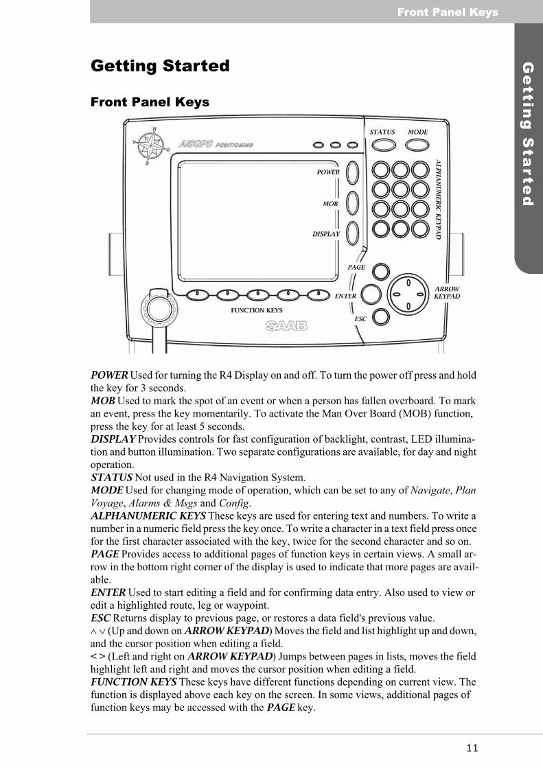
POWER Used for turning the R4 Display on and off. To turn the power off press and hold the key for 3 seconds.MOB Used to mark the spot of an event or when a person has fallen overboard. To mark an event, press the key momentarily. To activate the Man Over Board (MOB) function, press the key for at least 5 seconds.DISPLAY Provides controls for fast configuration of backlight, contrast, LED illumina-tion and button illumination. Two separate configurations are available, for day and night operation.STATUS Not used in the R4 Navigation System.MODE Used for changing mode of operation, which can be set to any of Navigate, Plan Voyage, Alarms & Msgs and Config.ALPHANUMERIC KEYS These keys are used for entering text and numbers. To write a number in a numeric field press the key once. To write a character in a text field press once for the first character associated with the key, twice for the second character and so on.PAGE Provides access to additional pages of function keys in certain views. A small ar-row in the bottom right corner of the display is used to indicate that more pages are avail-able.ENTER Used to start editing a field and for confirming data entry. Also used to view or edit a highlighted route, leg or waypoint.ESC Returns display to previous page, or restores a data field's previous value.∧ ∨ (Up and down on ARROW KEYPAD) Moves the field and list highlight up and down, and the cursor position when editing a field.< > (Left and right on ARROW KEYPAD) Jumps between pages in lists, moves the field highlight left and right and moves the cursor position when editing a field.FUNCTION KEYS These keys have different functions depending on current view. The function is displayed above each key on the screen. In some views, additional pages of function keys may be accessed with the PAGE key.

Front Panel Keys
12
How to Operate the R4 Display
Views and Function Keys
The user interface is built upon a number of views, organized in four different modes. The different views are reached with the function keys below the screen and the ESC and PAGE keys on the right side of the front panel. The mode is changed by pressing the MODE key followed by the function key corresponding to the desired mode.
Use the function keys to step into a specific view and ESC to get back one level. PAGE provides access to additional pages of function keys in some views. An example view is shown below. In the following sections of the manual the views of the R4 Navigation Sys-tem are described.
The function keys are view-specific and the function of each key is specified with a label on the screen. Note that unlabelled keys are not active in that specific view. Also, in some views the function keys might serve as switches, e.g. toggling a parameter.
The status bar of the system is present in all views at the top of the screen, and further described in section “Status Bar” on page 16.
Change Settings
Several of the views in the R4 Navigation System contain parameters that can be edited. To edit a parameter, select it by using the ∧ ∨ < > keys and press ENTER. Then enter data in one of four ways:
• Numbers: Press the ALPHANUMERIC KEY that corresponds to each digit. To delete a digit, press function key Backspace.
• Text: Press the ALPHANUMERIC KEY that corresponds to each character. Press the key once for the first character, twice for the second character and so on. Press the key marked with a dot twice, where allowed, to bring up a menu for entering special characters. To delete a character, press function key Backspace. To change between upper and lower case letters, press function key Capslock (if present).
• List of predefined values: Use the ∧ ∨ keys to select between the predefined values.
• Bar graph data: Use the < > keys to increment or decrement the parameter.
System status
Function key labelleading to a subview
bar

13
Ge
tting
Sta
rted
Front Panel Keys
Press ENTER when done. If desired, use the ∧ ∨ < > keys to select a new parameter to be edited, else press function key Apply and Exit.
Use the ESC key to undo changes and to return to the previous view.
Alarm Pop-ups
The R4 Display features alarm pop-ups that can appear any time during operation. To ac-knowledge an alarm message, press ENTER. An example is shown below.
For more information on alarms see the Reference, section “Alarm Pop-ups” on page 41. For alarm definitions see Appendix, section “Alarm Messages” on page 123.
Turning On and Off the R4 Display
To turn on the R4 Display, press the POWER key. The LEDs on the display will blink momentarily, indicating that the R4 Display is starting up. Any alarm active when the dis-play is started will be indicated by Alarm pop-ups, as described above. Press ENTER to acknowledge any present alarm, and the corresponding pop-up will be removed.
The R4 Display will power up in the Navigate mode, showing the Position view. The dif-ferent modes and the basic operation of the R4 Navigation System are described in the following sections.
To power off the R4 Display, press and hold the POWER key for 3 seconds, until the screen goes black.

System Modes
14
System Modes
The user interface of the R4 Display has four different system modes, which each corre-spond to different types of user activities.
The four modes are Navigate, Plan Voyage, Alarms & Msgs and Config. Current mode is changed by pressing the MODE key, which will bring up the function key labels illustrat-ed below. Press the corresponding function key to enter the desired mode.
The different modes are described below, with illustrations of typical mode views.
Navigate Mode
The Navigate mode is used under normal ship operation. It supports viewing bearing and distance to the next waypoint, skipping waypoints, plotting the active route, editing the active route, monitoring cross-track error and viewing sensor information such as current depth, speed, heading and position. It also supplies functions for viewing current GPS and Beacon status. This mode is described in detail on page 43 and onwards in the Reference chapter.
Plan Voyage Mode
The Plan Voyage mode supports viewing, creating and deleting waypoints and routes, as well as starting to sail a route or sailing directly to a specific location. This mode is de-scribed in detail on page 69 and onwards in the Reference chapter.
Function keysfor selecting system mode

15
Ge
tting
Sta
rted
System Modes
Alarms & Msgs Mode
The Alarms & Msgs mode supports functions for monitoring current system status. This includes functions for viewing present and previous alarms, definition of scheduled time alerts, clearing the alarm log and viewing received DGPS messages. This mode is de-scribed in detail on page 91 and onwards in the Reference chapter.
Config Mode
The Config mode comprises functions used to setup and configure the R4 Navigation Sys-tem. It includes functions for modifying visual and sound settings, navigation settings, disable and enable different alarms, used units, GPS and beacon settings, serial port set-tings and viewing system information. This mode is described in detail on page 99 and onwards in the Reference chapter.
Functions Accessible Regardless of Mode
Functions associated with the MODE, DISPLAY, MOB and POWER keys are accessible regardless of mode. These keys provide functionality for switching system mode, chang-ing display settings, marking the position in case of accident (MOB) or other event (event mark) and for turning the display on and off.

Status Bar
16
Status Bar
The top of the screen of the R4 Display always displays a summary of the system’s status. See illustration below.
If a valid navigation position is available, it is displayed to the left. The status icons are displayed in the middle, and to the right current RAIM accuracy level (in meters) and time is shown. It is possible to select whether displayed time shall refer to UTC or a local time frame defined by an offset setting in the Time view as described in section “Time Config” on page 101.
As an option, the position displayed in the status bar may be replaced by the name of the waypoint the system currently is navigating towards. Which data to display can be select-ed in Config mode by the ‘Status Information’ parameter in the Nav Config view (See “Nav Config” on page 103.).
Status Icons
The status icons that can be displayed are:
Unread DGPS message Active alarms
Redundant operation status, being one of: Redundant operation active Redundant operation active. Synchronizing from external unit. Redundant configuration has been enabled but no communication is established.
GPS status, being one of: DGPS based on external differential corrections applied through the User 1 port DGPS based on corrections from the internal radio beacon receiver (DGPS version) DGPS based on SBAS differential corrections Navigating without differential corrections No valid position information No communication with the R4 Navigation Sensor
DGPS Integrity Alert, displayed immediately to the right of GPS status when active.
HDOP status indication (active if HDOP is above 4)
The icons are also described in section “Icon Description” on page 36 in the Reference chapter.
Current position
Current RAIM
Current time (UTC)Status icons
accuracy level
Current time(local)

17
Ge
tting
Sta
rted
Status Bar
RAIM Accuracy Level
The RAIM accuracy level specifies (in meters) the desired position accuracy used to cal-culate current RAIM status. RAIM is a GPS integrity monitoring scheme that evaluates the quality of position data and compares it to the specified accuracy level.
The LEDs on the front of the R4 display will show the RAIM status. The green LED in-dicates safe state; the calculated position accuracy is better than the set accuracy level. The yellow LED indicates caution state; the system is unable to safely determine if the position accuracy is better or worse than the set accuracy level. The red LED indicates un-safe state; the calculated position accuracy is worse than the set accuracy level. The LEDs and RAIM states are further described in section “Status LEDs” on page 35.
The used RAIM accuracy level is the latest specified accuracy level, ei-ther specified manually or by a leg setting in the sailed route. An under-lined accuracy level indicates that a manually entered RAIM level
overrides RAIM levels set in the active route. This is illustrated in the figure to the left.
For details of this and on how to set current RAIM accuracy level, see section “Set RAIM” on page 49 in the Reference chapter.

Show Current Position
18
Show Current Position
The R4 Display will power up in the Position view. The view shows current position, speed over ground (SOG) and course over ground (COG) as reported by the R4 Naviga-tion Sensor. If no position information is available from the R4 Navigation Sensor, the view shows the last available values and the time they were acquired. For details on this view, refer to the Reference chapter, section “Position” on page 45.
The view is present in Navigate mode, accessed by pressing MODE followed by the func-tion key NAVIGATE. The view is then accessed by pressing function key Position.
Create Waypoints
Waypoints are the basis for ship navigation. A waypoint is a position on the earth surface that is given a unique name and stored in the memory of the R4 Display. Waypoints can be entered in several different ways, and used for building routes as well as for direct nav-igation to a specific position.
Creating waypoints is performed in the Waypoint List view in Plan Voyage mode. Plan Voyage mode is accessed by pressing the MODE key followed by the PLAN VOYAGE function key. The Waypoint List view is then accessed by pressing function key Way-point List.

19
Ge
tting
Sta
rted
Show Current Position
Create New Waypoint
Access the Waypoint List view as described above. Press the function key Create New Wp. The Create Waypoint view is displayed.
To name the waypoint, select the Name field using ∧ and press ENTER. The field be-comes editable and the following function keys are displayed.
Enter a descriptive name for the waypoint you are creating, using the alphanumeric key-pad. Use the Backspace function key to erase characters, and the Capslock function key to change between upper and lower case letters. Press ENTER when done.
The Lat and Long values are per default set to the latitude and longitude of current posi-tion. If a different position is desired, select each field to modify using ∧ ∨, press ENTER and use < > keys to select the digits to alter. Enter new digits using the alphanumeric key-pad and press ENTER when done.
To create the waypoint, press function key Apply and Exit.

Sail To a Waypoint
20
Sail To a Waypoint
The R4 Navigation System supports sailing directly to a waypoint. Starting to sail to a waypoint is done in Plan Voyage mode, just as creating waypoints. The mode is accessed by pressing the MODE key followed by the PLAN VOYAGE function key. The Sail To function is present in the Route List view, accessed by function key Route List. The view is illustrated below.
The Route List view can also be accessed from the Navigate mode as follows. Press the MODE key followed by the NAVIGATE function key. Then press the PAGE key in order to access a second page of function keys that includes the Route List key.
In the Route List view, press the function key Sail To Wp/Pos to sail to a specific loca-tion. The following view is displayed.
To select the destination waypoint, press function key Select Dest. This brings up the Select Waypoint view.
Destinationwaypoint(none selected yet)

21
Ge
tting
Sta
rted
Sail To a Waypoint
Use the ∧ ∨ keys to highlight the desired waypoint. The find and sort functions, described in the Reference in section “Route List” on page 71, can also help in finding the correct waypoint. Once the desired waypoint has been highlighted, press function key Select Waypoint to select it as destination.
Press function key Sail to start sailing to the selected destination. The Nav view is shown, as described and illustrated in section “Navigate Towards a Waypoint and Follow a Route” on page 30.

Create a Route
22
Create a Route
A route is a sequence of waypoints, which is used to navigate from a start waypoint to an end waypoint. The R4 Navigation System supports up to 100 different routes.
Planning and creating a route is done in the Plan Voyage mode. This mode is accessed by pressing MODE followed by the function key PLAN VOYAGE. The Route List view is then accessed by pressing function key Route List. The view lists all existing routes in the system, with information on the number of waypoints and length of each route. For a detailed description of the Route List view and all its function keys, refer to the Reference chapter, page 71.
Create a new route by pressing the function key Create New Rte. The Create Route view is displayed. Use ∧ ∨ to select the Name field and press ENTER.
Enter a descriptive name for the route you are creating, using the alphanumeric keypad. Use the Backspace function key to erase characters, and the Capslock function key to change between upper and lower case letters. Press ENTER when done.

23
Ge
tting
Sta
rted
Create a Route
Once a name for the route has been entered, press ∨ to bring focus to the still empty way-point list of the route. This brings forth the function keys for modifying waypoints in the route, as visualized in the following figure.
A walk-through on how to insert waypoints into the route is given below.
Insert Waypoints Into the Route
To insert waypoints into an empty route, press function key Insert Waypoints. Once pressed, the Insert Waypoints view is displayed.
The view lists all existing waypoints in the system, sorted alphabetically. The view is de-scribed in detail in section “Insert Waypoints” on page 82 of this manual.
If the desired waypoint exists in the list, use ∧ ∨ to highlight it and press the Insert Way-point function key.
If no suitable waypoint exists, create one by pressing the Create New Wp function key. The Create Waypoint view is shown. Enter a name for the waypoint and its position, as previously described in section “Create Waypoints” on page 18. Once the waypoint has been created by pressing Apply and Exit, the Insert Waypoints view is shown again. Use ∧ ∨ to highlight the created waypoint and press the function key Insert Waypoint to in-sert it into the route.

Create a Route
24
Add more waypoints to the route by repeating the procedure(s) described above. Once a waypoint has been inserted, a number will appear in a small box to the right of the way-point indicating the insertion order into the route.
When all (or a suitable number of) waypoints have been inserted press the Return func-tion key. The Create Route view is displayed again with the waypoints added.
To insert more waypoints into the route, select the desired location for the waypoint in the route and press one of the function keys Insert Wps After or Insert Wps Before. The former inserts waypoints after the highlighted position, whereas the latter inserts the way-points before the highlighted position. Repeat the procedure described above to select and insert desired waypoints.

25
Ge
tting
Sta
rted
Create a Route
Adjusting Navigation Algorithm and RAIM Accuracy Level
To modify the settings for the legs in the route, press function key Route Legs while re-maining in the Create Route view. This makes the view display the legs in the route, as illustrated below.
The column marked “A” indicates the navigation algorithm set for each leg. An R indi-cates rhumb line and a G great circle navigation. The “RAIM” column shows the RAIM accuracy setting set for each leg. A “-” indicates that sailing the leg leaves the present RAIM level unchanged, while a number indicates that a RAIM accuracy level has been set for the leg.
Use ∧ ∨ to highlight the leg to adjust settings for. Once highlighted, press ENTER. This brings up the Edit Leg view.
To modify the navigation algorithm, select the Navigation Algorithm field using ∧ and press ENTER. Select the desired navigation algorithm using ∧ ∨ and press ENTER again when done.
To set a RAIM accuracy level for the leg, use ∨ to select the RAIM Accuracy field and press ENTER. Use ∨ to select the Level entry and press ENTER. A box to enter the accuracy level appears, as illustrated to the right.
Navigation
RAIM accuracy
algorithm
setting
Create a Route
26
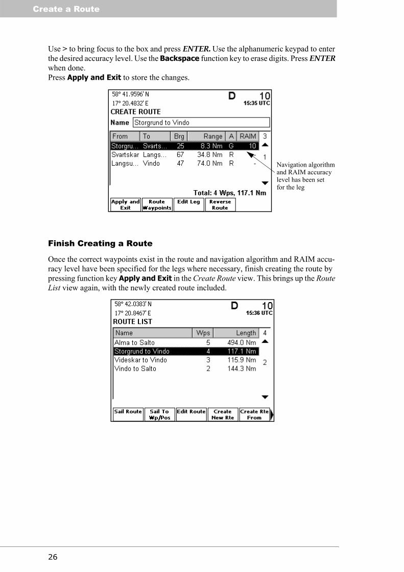
Use > to bring focus to the box and press ENTER. Use the alphanumeric keypad to enter the desired accuracy level. Use the Backspace function key to erase digits. Press ENTER when done.Press Apply and Exit to store the changes.
Finish Creating a Route
Once the correct waypoints exist in the route and navigation algorithm and RAIM accu-racy level have been specified for the legs where necessary, finish creating the route by pressing function key Apply and Exit in the Create Route view. This brings up the Route List view again, with the newly created route included.
Navigation algorithmand RAIM accuracylevel has been setfor the leg

27
Ge
tting
Sta
rted
Review an Existing Route
Review an Existing Route
To review the details of an existing route, go to the Route List view. The view can, if in another view in the Plan Voyage mode, be accessed by pressing the ESC key a few times until the top level view of the mode is reached, followed by the Route List function key. The mode is accessed by pressing MODE followed by function key PLAN VOYAGE.
Select the desired route using ∧ ∨ and press the ENTER key. The View Route view is dis-played.
When first entered, this view displays the waypoints that the route is made up of. To walk through the route, use ∧ ∨ to scroll through the list. To view the full name, position and time of creation for a specific waypoint, highlight the waypoint using ∧ ∨ and press EN-TER or the VIEW WAYPOINT function key. The View Waypoint view is displayed as il-lustrated below.
To leave the view and get back to the View Route view, press ESC.

Review an Existing Route
28
Press function key Route Legs to display the legs the route is made up of. The following view is shown.
Use ∧ ∨ to scroll through the list. For each leg, the initial bearing to head on each leg is shown, as well as its length. The navigation algorithm and any RAIM level set on that leg is also displayed. To get details of a specific leg, select it using ∧ ∨ and press ENTER or the VIEW LEG function key. The View Leg view is shown, as illustrated below.
Press ESC to return to the View Route view.
When done reviewing the route, press the Sail Forward or Sail Reverse function keys to sail the route, or press the ESC key to return to the Route List view.
Navigation algorithmfor the leg
RAIM accuracyset for the legsetting

29
Ge
tting
Sta
rted
Start Sailing a Route
Start Sailing a Route
Access the Route List view. The view is present in Plan Voyage mode, accessed by press-ing the MODE key followed by the PLAN VOYAGE function key. If in another view in the mode, pressing ESC a few times will bring up the top level view of the mode with function keys for accessing the main views of the mode. Press function key Route List
A short-cut to the Route List view is also available by a function key at the second page of the top level view in Navigate mode as described on page 43 of this manual.
Highlight the route to sail using ∧ ∨, and press the function key Sail Route. The Sail Route view is displayed, illustrated below.
Press function key Sail Forward to start sailing the route in the direction it is shown. Use Sail Reverse to sail the route in its reverse direction.
Once a route is to be sailed, a copy of the selected route is made into the active route and the Nav view is displayed, as illustrated below.

Start Sailing a Route
30
For information on how to navigate following a route, see the next section.
Navigate Towards a Waypoint and Follow a Route
Navigating towards a waypoint and on a route are done in Navigate mode. To enter this mode press the MODE key followed by the function key NAVIGATE. If in another view in this mode, press ESC a few times to bring up the top view of the mode. Press function key Nav to show the Nav view. This view contains several vital functions to aid the op-erator in navigating towards waypoints and following routes. The view is illustrated be-low.
When sailing towards a waypoint using the Sail To function, and when sailing towards the first waypoint of the active route, the view shows distance and bearing towards the next waypoint. When having passed the first waypoint of the active route, the view also starts displaying current cross-track error.
To navigate towards the next waypoint, keep current course over ground (COG) close to the bearing to the next waypoint (BRG). In the lower rectangle, current course deviation is illustrated by the distance between the bold vertical bar and the thin center line. To steer to the next waypoint, make the bold vertical bar stand over the center line. The rectangle can represent a course deviation of ± 30°.
Bearing to thenext waypoint
Current courseover ground
Distance tothe next way-point
Current speedover ground

31
Ge
tting
Sta
rted
Start Sailing a Route
Once the first waypoint of the active route has been reached, the view begins displaying current cross-track error. The cross-track error is the distance between current position and the planned track, and is visualized by the distance between the boat symbol and the thin center line. The cross-track error scale of the rectangle is visualized by the Limit val-ue. See the below illustration.
To more quickly reduce the cross-track error, steer back towards a point on current leg closer to you than the next waypoint. While steering back to current leg, current course indicator should stand on the opposite side of the center line compared to the cross-error symbol, as illustrated above.
If desired, current cross-track error can be set to zero by pressing function key Reset XTE. It is also possible to manually skip the next waypoint by pressing function key Skip Way-point.
The view is described in detail in section “Nav” on page 50 in the Reference chapter. The cross-track error limit is configured in the Nav Config view, described on page 103.
Plot the Active Route
The position of the ship and the active route can be graphically visualized in the Plot view. To enter this view press the MODE key followed by the function key NAVIGATE. If in another view in this mode, press ESC a few times to bring up the top view of the mode. Press function key Plot. The view plots the waypoints and legs of the active route The waypoint currently used for navigation is indicated by a filled symbol. The plot also vis-ualizes cross-track error limit of current leg, as shown below.
Use the function keys Zoom In and Zoom Out to increase or decrease the scaling of the plot. By pressing the function key Show Track the sailed track is shown as well. Refer to page 59 for a detailed description of the view.
Current cross-track error Current course deviationfrom bearing to nextwaypoint
The lengthof the side ofthe Plotquadrant

Start Sailing a Route
32
View the Active Route
To see the total and remaining length of the active route, enter the Active Route view from the top level view in Navigate mode by pressing function key Active Route. The view also illustrates the remaining waypoints of the route and includes functions for editing the active route, setting an ETA target and manually selecting which waypoint in the route to navigate towards. It is also possible to end the active route by pressing the function key End Route. Optional views with display of additional information are also available.The view is described in detail in section “Active Route” on page 53.
Alarm List Current alarm status can be viewed under the Alarm List view, in the Alarms & Msgs mode. To enter the mode, press the MODE key followed by the ALARMS & MSGS function key. Then press function key Alarm List to enter the view. Active alarms are marked with an exclamation mark (!).
On entrance, the view only shows status of enabled alarms. To show alarms that have been disabled, press the function key Show Disabled. For more information on alarm mes-sages see Appendix, section “Alarm Messages” on page 123. The Alarms & Msgs mode and associated views are described on page 91 and onwards.

33
Ge
tting
Sta
rted
Start Sailing a Route
Visual Settings
The display backlight, contrast, LED illumination, button illumination and day or night settings can be changed in the Visual Config view. Changes made in this view directly ef-fect the corresponding visual setting.
To enter this view, press the DISPLAY key. The following view is shown.
To change between day and night settings, press Switch to Day or Switch to Night. The day and night settings are stored separately, so different settings can be specified for day and night operation. To change backlight, contrast, LED illumination or button illu-mination, press the corresponding function key. Regardless if the Backlight, Contrast, Led Illum. or Button Illum. function key is pressed, a view with a bar graph is shown as illustrated below.
Use < > to decrease or increase the value of the selected setting. The corresponding screen or illumination setting is directly affected as the bar is moved.
To exit the Visual Config view, press DISPLAY or ESC.

Start Sailing a Route
34
This page is intentionally empty.

35
Re
fere
nc
eStatus LEDs
Reference
Status LEDs
The following sections describe the status indicating light emitting diodes (LEDs) of the R4 Display and R4 Navigation Sensor.
R4 Display LEDs
The three LEDs located above the screen of the R4 Display are used to indicate the RAIM accuracy status of the ship’s current GPS position.
Green LED (Safe state)The green LED indicates, when lit, safe state. It is lighted if the probable position error is less than the RAIM accuracy level with more than 95% certainty.
Yellow LED (Caution state)The yellow LED indicates, when lit, caution state. It is lighted if the system can not safely determine if the position accuracy is better or worse than the current RAIM accuracy lev-el. It is also lighted if no position is available.
Red LED (Unsafe state)The red LED indicates, when lit, unsafe state. It is lighted if the position error exceeds the current RAIM accuracy level with more than 95% certainty.
R4 Navigation Sensor LEDs
PWR LEDThe red LED marked “PWR” indicates, when lit, that power is applied to the R4 Navigation Sensor.
GPS LEDThe yellow LED marked “GPS” indicates, when continuously lit, that the R4 Navigation Sensor has obtained a solid GPS lock.
CORR LEDThe yellow LED marked “CORR” indicates, when continuously lit, that the R4 Naviga-tion Sensor has achieved a solid radio beacon lock or a SBAS lock with a bit error rate (BER) better than 150. If the SBAS BER is higher than 150 but the receiver is still locked, this LED will blink showing that the lock is marginal. This LED is also lit while using external DGPS corrections input through the User1 port.
DGPS LEDThe green “DGPS” LED indicates that the R4 Navigation Sensor has achieved a differen-tially corrected position. It is continuously lit when the range residuals in the position so-lution have settled below a threshold value.

Icon Description
36
Icon Description
The following sections describes the different icons that can appear on the screen of the R4 Display.
Message Symbols
Unread DGPS message
Redundant Operation Status Symbols
Redundant operation active.
Redundant operation active. Synchronizing from external unit.
Redundant configuration enabled. No communication with external unit
GPS Status Symbols
Position available and corrected using externally input corrections.
Position available and corrected using corrections from the internal radio beacon receiver (DGPS version only)
Position available and corrected using SBAS differential corrections
Position available, not differentially corrected
No valid position information
No communication with the R4 Navigation Sensor
DGPS Integrity Alert active. Details of alert displayed in the GPS Status View
The HDOP value has exceeded limit
Miscellaneous Symbols
Active Alarm(s)

37
Re
fere
nc
eAdjusting Settings
Adjusting Settings
If desired, some presentation and navigation characteristics of the R4 Display can be ad-justed to the user’s preferences. The most central parameters that can be adjusted are briefly described below.
SOG and COG smoothingThe R4 Navigation System supports smoothing of SOG and COG values for more stable readings. See section “GPS Config” on page 107.
Source of differential correctionsThe R4 Navigation System can be set to use IALA radio beacon (DGPS version only) or SBAS differential corrections. It is also possible to turn off the use of differential correc-tions or use external corrections in RTCM SC-104 format received on the User Port 1. See section “GPS Config” on page 107.
Beacon receiver tuning mode (DGPS version only)The tuning and bit rate modes of the R4 DGPS sensor internal beacon receiver can be set to manual or automatic modes as described in section “Beacon Config” on page 109.
Maximum age of differential correctionsThe maximum allowed age of differential corrections can be configured. Default is 120 seconds. See section “GPS Config” on page 107.
Adjust enabled and disabled alarmsEnable alarms for those alarm conditions that indications are desired for. Per default, sev-eral of the alarms are disabled. Alarms that are invalid in the specific system configuration can remain disabled. If not, such alarms will always be active. Adjusting alarms is de-scribed in section “Alarm Config” on page 105.
Route leg default navigation algorithmThe default navigation algorithm for created legs can be set to one of Great Circle and Rhumb Line. The factory default is Rhumb Line. The different algorithms are described in chapter “Concepts and Terminology” on page 9, and selection of default algorithm in section “Nav Config” on page 103.
Waypoint pass criterionThe waypoint pass criterion can be set to one of Manual, Distance, Bisector Line and Per-pendicular Line. The different pass criteria are described in chapter “Concepts and Ter-minology” on page 9, and selection of criterion in section “Nav Config” on page 103.
Cross-track error limitThe cross-track error limit determines the allowed cross-track error, and thus also when the XTE Limit Exceeded alarm shall be raised. The parameter is described in section “Nav Config” on page 103.
Distance or time for waypoint approach alarmThe distance to or estimated time before arrival at the next waypoint where an Approach-ing Waypoint alarm is raised can be configured, as described in section “Nav Config” on page 103.

Adjusting Settings
38
UTC or local time frameIt can be selected whether displayed time shall refer to UTC or a to user defined local time frame with constant offset from UTC. Refer to section “Time Config” on page 101.
Range, speed and depth unitsThe units used for displaying range, speed and depth values can be configured. Configu-ration of units is described in section “Units Config” on page 106.
Route leg default RAIM accuracy levelThe default RAIM accuracy level set when specifying accuracy level for a leg. Configu-ration of the parameter is described in section “Nav Config” on page 103.
Position or next waypoint in status barStatus bar information at the top left corner of the display can be selected between current position (if available), or the name of the waypoint that the system currently is navigating towards. Refer to “Nav Config” on page 103.

39
Re
fere
nc
eMan Over Board
Man Over Board
The MOB (Man Over Board) key can be used to simultaneously mark a position and start-ing to navigate towards it, for quick response to emergency situations.
To activate the MOB function, press and hold the MOB key for at least 5 seconds.
Once activated, a MOB waypoint is created and the R4 Navigation System will start nav-igate towards that waypoint. The active route is suspended until the MOB functionality is deactivated. The R4 Display will show a scalable Plot view, plotting the position of both the MOB waypoint and the ship, as well as displaying the bearing and distance to the MOB waypoint and the ship’s current speed and course over ground. See illustration be-low.
Clear MOB and resume navigation on active route1. Press function key Clear Mob.2. Answer Yes to the confirmation dialog and press ENTER.
Show Time In Water (TIW)1. Press function key Show TIW. Press function key Show Time Act. to return
to showing the time MOB was activated.
The system can store up to 20 MOB waypoints at the same time. If more MOB waypoints are created, the oldest will be removed. If the information in a MOB waypoint is to be stored for long term reference, it is therefore recommended to copy it to another medium or store it in a normal, non-MOB waypoint (which is easily achieved using the Create Wp From function key in the Waypoint List view, described on page 71 and onwards).
MOB waypoints are named “MOB date time” and shown in the Waypoint List view.
Time activated

Event Mark
40
Event Mark
The MOB key can, as well as being used for emergency situations as described above, also be used to quickly create a waypoint for easy marking of current position. To create a waypoint for the current position, press the MOB key momentarily. Hold it down no more than 1 second.
Pressing MOB momentarily brings up the following view:
The Lat and Long values will be set up to position of the ship when the MOB key was pressed. The waypoint is also given a default name. To change its name, do the following:
1. Select the Name field using ∧. Press ENTER.2. Use the alphanumeric keypad to enter name text, and the Backspace function
key to erase characters. Use function key Capslock to change between upper and lower case letters.
3. Press ENTER when done.
Press Apply and Exit to create the waypoint. Press ESC to abort creating the waypoint. The Create Waypoint view is described in detail on page 90.

41
Re
fere
nc
eAlarm Pop-ups
Alarm Pop-ups
Pop-up windows can appear any time during system operation to notify the user of an event or alarm condition. To acknowledge an alarm and close the pop-up window, press ENTER. Active alarms are listed in the Alarm List view described on page 92. For expla-nation of different alarms, see Appendix, section “Alarm Messages” on page 123.
It is possible to disable alarms that are invalid for the specific system configuration. If not disabled, such alarms will otherwise always be active. For example, if no depth sensor is connected to the system then the alarm Depth Data Lost should be disabled. This is de-scribed in section “Alarm Config” on page 105.

Changing System Mode
42
Changing System Mode
The R4 Display has four system modes: Navigate, Plan Voyage, Alarms & Msgs and Con-fig. The system modes corresponds to the kind of operation the user is performing. An overview of the different modes is present in section “System Modes” on page 14. Each mode is also described in detail in the following sections of this chapter.
Accessing Navigate mode views when in a different mode1. Press MODE key.2. Press function key NAVIGATE.3. To show the second page of main views, press PAGE.4. Press the function key associated with the desired view.
Accessing Plan Voyage mode views when in a different mode1. Press MODE key.2. Press function key PLAN VOYAGE.3. Press the function key associated with the desired view.
Accessing Alarms & Msgs mode views when in a different mode1. Press MODE key.2. Press function key ALARMS & MSGS.3. Press the function key associated with the desired view.
Accessing Config mode views when in a different mode1. Press MODE key.2. Press function key CONFIG.3. To show the second page of main views, press PAGE.4. Press the function key associated with the desired view.

43
Re
fere
nc
eNavigate Mode - Overview
Navigate Mode
The Navigate mode contains a set of views related to typical ship navigation tasks during normal voyage operation. The mode is entered by pressing the MODE key followed by function key NAVIGATE. Press ESC a few times anywhere in the mode for access of top level function keys.
Overview
The top level function keys of the Navigate mode are illustrated below. Press ESC a few times anywhere in the mode to bring them up
A second page of function keys becomes available by pressing the PAGE key as illustrat-ed below.
• Position shows the last calculated position, speed and course over ground and has subviews for GPS and radiobeacon status, satellite information and RAIM.
• Nav shows textual and graphical information on the next waypoint as well as current speed and course over ground, cross-track error and ETA.
• Active Route lists the remaining waypoints in the active route and enables func-tions for editing the route, setting ETA target and manually selecting which waypoint in the route to navigate towards.
• Plot shows a plot of the waypoints and legs of the active route and the cross-track error limit of current leg.
• User Defined gives access to up to five user configurable views, capable of dis-playing different types of navigation and sensor data.
• Trip Logs provides functions for calculation of travelled distances and average speeds.
• Anchor Watch provides a function for activation of an alarm when the deviation from a reference position exceeds a preset range.
• Route List provides a short-cut to the Route List View from which it is possible to activate a route or select a waypoint for navigation.
First Page
Second Page

Navigate Mode - Overview
44
Below is a graphical overview of the different views present in Navigate mode.
45
Re
fere
nc
eNavigate Mode - Position
Note: The Beacon Status view and subviews is only present when using the R4 DGPS Navigation Sensor.
The views are further described below.
Position
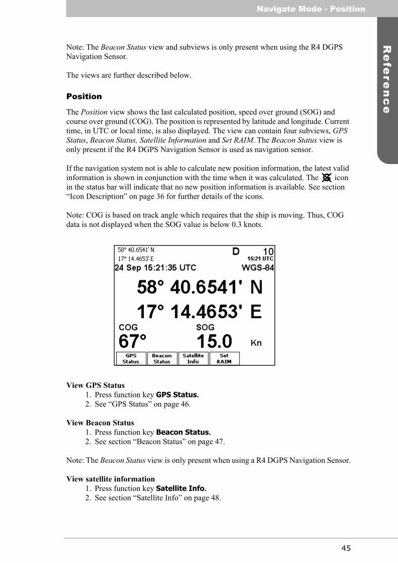
The Position view shows the last calculated position, speed over ground (SOG) and course over ground (COG). The position is represented by latitude and longitude. Current time, in UTC or local time, is also displayed. The view can contain four subviews, GPS Status, Beacon Status, Satellite Information and Set RAIM. The Beacon Status view is only present if the R4 DGPS Navigation Sensor is used as navigation sensor.
If the navigation system not is able to calculate new position information, the latest valid information is shown in conjunction with the time when it was calculated. The icon in the status bar will indicate that no new position information is available. See section “Icon Description” on page 36 for further details of the icons.
Note: COG is based on track angle which requires that the ship is moving. Thus, COG data is not displayed when the SOG value is below 0.3 knots.
View GPS Status1. Press function key GPS Status.2. See “GPS Status” on page 46.
View Beacon Status1. Press function key Beacon Status.2. See section “Beacon Status” on page 47.
Note: The Beacon Status view is only present when using a R4 DGPS Navigation Sensor.
View satellite information1. Press function key Satellite Info.2. See section “Satellite Info” on page 48.

Navigate Mode - Position
46
Set RAIM accuracy1. Press function key Set RAIM. 2. See section “SBAS Info” on page 48.
GPS StatusThe GPS Status view displays information related to the current navigation solution.
• Operating mode: NO GPS (no navigation solution), GPS (GPS only navigation solution) or DGPS (differentially corrected navigation solution).
• Number of GPS satellites from which signal is received and number of GPS sat-ellites currently used in the navigation solution.
• DGPS warning, related to an active DGPS Integrity Alert. The warnings that can be displayed are:
• No Signal. A correction source for GPS other than None has been selected in the GPS Configuration view and more than ten seconds have passed since new differential corrections were applied to the navigation solution
• Station Unhealthy. Correction source Beacon has been selected and the radio beacon station in use indicates an unhealthy status.
• Station Unmonitored. Correction source Beacon has been selected and the radio beacon station in use indicates an unmonitored status.
• Poor signal. Correction source Beacon has been selected and the word error rate of the received signal in use exceeds 10%.
• DGPS reference station ID. The reference identity of the currently applied dif-ferential corrections (if any).
• DGPS correction age. The time difference between navigation solution and ref-erence time for the applied corrections (if any).
• DGPS correction source: Beacon, SBAS, External or None (-).• Beacon receiver tuning mode: Manual or Frequency Scan. Only displayed
when correction source is Beacon.• RAIM accuracy limit. • RAIM status: Safe, Caution or Unsafe.
.
The RAIM status is also indicated by the LEDs on the front of the display unit. The green LED corresponds to the safe state, the yellow to caution state and the red to unsafe state.

47
Re
fere
nc
eNavigate Mode - Position
Beacon StatusThe Beacon Status view shows information related to the R4 DGPS Navigation Sensor’s beacon reception. The view is only accessible if an R4 DGPS Navigation Sensor is used as navigation sensor. The header will include DGPS warning information if beacon is se-lected as correction source and a DGPS Integrity Alert is active. The header will display ‘Not in Use’ if a correction source another than beacon is selected. Use ∧ ∨ to scroll in the list with following information.
• Reference Station ID: The reference identity of received corrections from the tuned beacon station.
• Tuned frequency.• Tuning mode. Current beacon receiver frequency selection mode: Manual or
Frequency Scan. When tuning mode is manual, a function key Auto Tuning is available for simple switch over to automatic tuning mode (frequency scan).
• Signal quality as determined by current word error rate. The signal is regarded as poor when word error rate exceeds 10%.
• Health indication received from the tuned beacon station.• Message throughput.• Word error rate, percentage of bad data words in the last 25 words received.• SNR, signal to noise ratio. Good SNR:s for the beacon signal range from 15
upwards.• Signal strength.• Bit rate.• Beacon receiver bit rate selection mode: Manual or Auto.• Firmware version for the internal beacon receiver.

Navigate Mode - Position
48
Satellite InfoThe Satellite Information view shows information relating to GPS satellites that the R4 Navigation Sensor is receiving or expecting to receive signals from. The view displays the ID, elevation and azimuth of each satellite, and current signal to noise ratio (SNR) of each satellite’s signal. The elevation value represents the satellite’s angular height above the horizon. The azimuth value represents the satellite’s angular horizontal position, counted clockwise from the north.
Use ∧ ∨ to scroll in the list.
SBAS InfoThe SBAS Information view shows information relating to the one or two geostationary SBAS satellites that the R4 Navigation Sensor is receiving or expecting to receive signals from. The view is reached from the Satellite Information view by function key SBAS In-fo. Identity (PRN number) and longitude of the satellite as well as elevation and azimuth angle from the current position to the satellite and bit error rate of the received signal is provided by the view. Additionally, when using SBAS as correction source the reference

49
Re
fere
nc
eNavigate Mode - Position
id of applied corrections is displayed in the header of the view. The header will display ‘Not in Use’ if a correction source another than SBAS is selected
Set RAIMThe Set RAIM view is used to modify the used RAIM accuracy level. The RAIM accuracy level is always set in meters. In the case the active route has RAIM accuracies specified for any of its legs, a RAIM accuracy level specified in this view will override the RAIM settings in the active route. If this is the case, you will be warned before any RAIM level is set.
When overriding active route RAIM accuracy levels, the RAIM accuracy level indication will appear underlined, as illustrated in the figure to the right. When overriding, accuracy levels specified in the active route does not affect the used RAIM accuracy level. To stop RAIM overriding, enter the Set RAIM view and press the Cancel Override function key that is present in this view when the override condition is active. The override RAIM condition is also automat-ically cancelled when reaching the end of the active route.
Set RAIM accuracy level (in meters)1. Press ENTER.

Navigate Mode - Nav
50
2. Use the alphanumeric keypad to enter new the RAIM accuracy level in meters. Use the Backspace function key to erase digits. Press ENTER when done.
3. Press function key Apply and Exit to store the changes.4. If the active route contains any set RAIM accuracy levels, a warning pop-up
will be displayed.
5. Press ENTER to confirm that the set RAIM accuracy level should override the RAIM settings in the active route. Press > and ENTER to abort.
Cancel override condition1. Press the function key Cancel Override.
Note that this function key only is present when the override condition is active.
Nav
The Nav view presents fundamental navigation data and aids the user in navigating to-wards a waypoint and following a route. It presents information such as the bearing and range to the next waypoint, the ship’s current course over ground (COG) and speed over ground (SOG) and current cross-track error (if sailing on a route). The view is also an en-try point to the three partially different subviews Show Next Wp, Show ETA and Show Wp Info. Show Next Wp shows a close-up plot of the next waypoint. Show Wp Info shows the name of the active route, of the previous waypoint and of the current waypoint. Show ETA shows current Estimated Time of Arrival to the end point of the route as well as target ETA (if defined).
Note: COG is based on track angle which requires that the ship is moving. Thus, COG data is not displayed when the SOG value is below 0.3 knots.
Cross-track error
Cross-track error
Current course Bearing to waypoint Cross-track error symbol
range
limit
Nav algorithmand name ofnext waypoint

51
Re
fere
nc
eNavigate Mode - Nav
The rectangle in the lower part of the view visually represents current navigation infor-mation, as illustrated in the figure above. The difference between present course and the course to head to exactly navigate towards next waypoint is illustrated by the distance be-tween the bold vertical bar and the center line. The bold vertical bar represents current course and the center line the bearing to the next waypoint. To steer towards the waypoint, make the bold vertical bar stand over the center line. The rectangle can represent a course deviation of ± 30 °.
If sailing on a route and having reached the first waypoint, the rectangle also presents cur-rent cross-track error, illustrated by the distance between the boat symbol and the center line. The cross-track error limit determines the scale of the rectangle; when the boat sym-bol is outside the rectangle the cross-track error limit has been exceeded and the “XTE Limit Exceeded” alarm will be raised (if enabled).
Reset cross-track error1. Press function key Reset XTE.
The cross-track error is set to zero by inserting an temporary waypoint at the current po-sition in the active route. The temporary waypoint will not be saved if the active route is saved.
Skip next waypoint1. Press function key Skip Waypoint.
Show next waypoint plot1. Press function key Show Next Wp.2. The central region of the display shows a close-up of the remaining leg to the
next waypoint oriented upwards. Initial bearing of next leg in the route and esti-mated time to go (TTG) to the next waypoint are also displayed The plot is scaled such as that the distance from the mid point lower edge of the plot area to the next waypoint equals current distance to the waypoint, unless this distance is less than 100 meters. As the waypoint is approached, it is possible to increase resolution by hiding the plot as described in the next step and then re-open it.
3. Hide the close-up by pressing function key Hide Next.

Navigate Mode - Nav
52
Show estimated time of arrival (ETA)1. Press function key Show ETA.2. Estimated time of arrival to the final waypoint in the active route is displayed. If
a target ETA has been set, it is displayed as well along with the speed necessary to reach the destination in time.
3. Hide the display of ETA by pressing function key Hide ETA.
Note: The calculation of ETA and TTG is dependant on the average SOG time parameter described in section “Nav Config” on page 103.
Show waypoint information1. Press function key Show Wp Info.2. The following view is displayed, including the name of the active route and the
next and previous waypoint.

53
Re
fere
nc
eNavigate Mode - Active Route
Active Route
The Active Route view shows information of the active route, including route name, route length, number of total and remaining waypoints, ETA and details of the remaining way-points.
From this view it is possible to access the Edit Active Route, Set Target ETA and Set Next Wp subviews. The Edit Active Route subview can be used to modify legs and waypoints of the active route. The Set Target ETA view can be used to set a target for Estimated Time of Arrival. The Set Next Wp view can be used to change the waypoint in the active route that currently is being navigated towards. The latter is useful to quickly skip to a certain position in the active route and to unpass a previously passed waypoint.
The Active Route view is illustrated below. It displays the remaining waypoints in the route. For the first waypoint in the list, current bearing and remaining distance to it is dis-played. For the other waypoints, initial distance and bearing to it—calculated from the waypoint before it—is displayed. For each remaining waypoint the navigation algorithm and RAIM setting used when sailing towards that waypoint is shown.
Alternate information sets relating to the active route can be displayed using the function key initially labelled Show Position as follows.
Press function key Show Position. Latitude and longitude of each waypoint is displayed.
The next waypointis shown first inthe list
Navigation algorithmand RAIM settingset for the leg tothe waypoint

Navigate Mode - Active Route
54
Press function key Show Acc Dist. Accumulated distance along the route to each way-point is displayed.
Press function key Show Wp ETA. Estimated time of arrival to each waypoint in the route is displayed.
Press function key Show Wp T.ETA (available only if a target ETA has been set). Target arrival time at each waypoint corresponding to the target ETA for the complete route is displayed.

55
Re
fere
nc
eNavigate Mode - Active Route
Press function key Show Brg/Dist. The default initial view of bearing and range be-tween waypoints is displayed once again.
Edit the active route1. Press function key Edit Route.2. The Edit Active Route view is displayed, as described in the section below.
Set target ETA (Estimated Time of Arrival)1. In the Active Route view press function key Set Target ETA. The ETA view is
shown, as illustrated below.
2. Press ENTER to start editing the target ETA corresponding to a goal for the arrival time at the final waypoint in the active route. The value is entered on the form MM-DD HH:MM (month, day, hour and minute). Use the alphanumeric keypad to enter digits. Use < > to select which digits to edit.
3. Press ENTER when done.4. Press function key Apply and Exit.
Unset target ETA1. Press function key Set Target ETA. The ETA view is shown, as illustrated
above.2. Press function key Clear Target ETA.

Navigate Mode - Active Route
56
Change waypoint to navigate towards1. In the Active Route view press function key Set Next Wp. The Set Next Way-
point view is shown, as illustrated below.
2. Highlight the waypoint that should be set as waypoint to navigate towards using ∧ ∨.
3. Press function key Select Waypoint.
Stop sailing current route1. In the Active Route view press function key End Route. A pop-up request for
confirmation will be displayed before the active route is terminated.
Edit Active RouteThe Edit Active Route view is used to modify the active route. It displays all waypoints and legs in the active route, regardless if they are passed or not and including waypoints created when resetting cross-track error in the Nav view. It is possible to modify naviga-tion algorithm and RAIM setting for each leg, as well as remove, modify and insert way-points. Changes made to the active route leaves the original route unaffected. It is however possible to save the active route and thus update the original route to reflect made changes.
Note: Waypoints named “XTE Reset-..” have been inserted into the route when resetting the cross-track error. When saving changes, they will not be stored. The original route will not be affected by changes made to legs towards or between such waypoints, nor will such legs be created in the original route. These waypoints are not viewed as part of the planned route.
57
Re
fere
nc
eNavigate Mode - Active Route
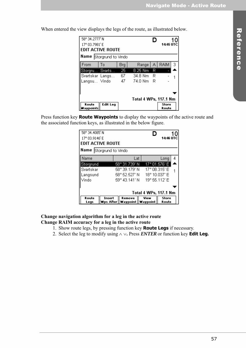
When entered the view displays the legs of the route, as illustrated below.
Press function key Route Waypoints to display the waypoints of the active route and the associated function keys, as illustrated in the below figure.
Change navigation algorithm for a leg in the active routeChange RAIM accuracy for a leg in the active route
1. Show route legs, by pressing function key Route Legs if necessary.2. Select the leg to modify using ∧ ∨. Press ENTER or function key Edit Leg.

Navigate Mode - Active Route
58
3. The Edit Leg view is displayed. See below.
4. To change the used navigation algorithm, select the Navigation Algorithm field using ∧ and press ENTER. Use ∧ ∨ to highlight the desired algorithm, and press ENTER when done.
5. To change the RAIM accuracy level for the leg, select the RAIM Accuracy field using ∨ and press ENTER. Select the desired RAIM setting using ∧ ∨. Select unchanged to set the leg to not affect the RAIM level at all.Select level to specify a RAIM accuracy level to switch to when navigating on the leg. Press ENTER.
6. If level was select above, then use > to bring focus to the right box that appeared when level was selected. Press ENTER and enter the RAIM accuracy level using the alphanumeric keypad. Use the Backspace function key to erase dig-its. Press ENTER when done.
7. Press the function key Apply and Exit to save made changes.
Insert waypoints into the active route1. Show route waypoints, by pressing function key Route Waypoints if neces-
sary.2. Use ∧ ∨ to highlight the waypoint after which the new waypoint should be
inserted.3. Press the function key Insert Wps After.4. The Insert Waypoints view is displayed (described on page 82). Highlight the
first desired waypoint to insert using ∧ ∨, possibly with the aid of the different sort and find functions present in the view.
5. Press function key Insert Waypoint.6. Repeat the procedure of highlighting and inserting waypoints until the desired
waypoints are selected for insertion into the route.7. Press function key Return.
View or edit a waypoint1. Highlight the waypoint to view or edit using ∧ ∨ and press ENTER or the View
Waypoint function key.2. The View Waypoint view is displayed, as described on page 88.3. If desired, press function key Edit Waypoint to edit the waypoint.4. The Edit Waypoint view is displayed, as described on page 88.
59
Re
fere
nc
eNavigate Mode - Plot
Remove waypoint from the active route1. Highlight the waypoint using ∧ ∨.2. Press function key Remove Waypoint.
Update the original route with the changes made in the active route1. Press function key Store Route.
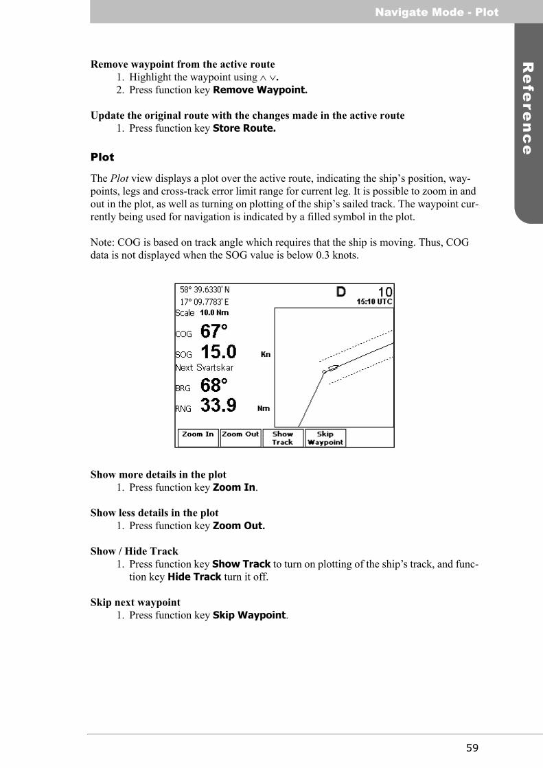
Plot
The Plot view displays a plot over the active route, indicating the ship’s position, way-points, legs and cross-track error limit range for current leg. It is possible to zoom in and out in the plot, as well as turning on plotting of the ship’s sailed track. The waypoint cur-rently being used for navigation is indicated by a filled symbol in the plot.
Note: COG is based on track angle which requires that the ship is moving. Thus, COG data is not displayed when the SOG value is below 0.3 knots.
Show more details in the plot1. Press function key Zoom In.
Show less details in the plot1. Press function key Zoom Out.
Show / Hide Track1. Press function key Show Track to turn on plotting of the ship’s track, and func-
tion key Hide Track turn it off.
Skip next waypoint1. Press function key Skip Waypoint.

Navigate Mode - User Defined
60
User Defined
The User Defined Views view provides functionality for creation of up to five user defined views. The information shown in the fields of each view can be configured as described below. The different types of information that can be shown (if available) are listed in the table below.:
Name Description
Empty No information displayed in this field.
Alg. Wp Current nav algorithm (GC or RL) and the name of the way-point that the system currently is navigating to.
Algo-rithm
Current nav algorithm (GC or RL).
BRG Bearing to next waypoint. Can be displayed in big (B), medium (M) or small (S) format.
COG Course over ground. Can be displayed in big (B), medium (M) or small (S) format. COG data is not displayed when SOG is below 0.3 knots.
Dialog Title
Name of view: ‘User Defined View #’ where # is a number from 1 to 5 depending on the current view.
DPT Depth information input through the serial interface. Can be displayed in big (B), medium (M) or small (S) format.
ETA Estimated time of arrival to the end waypoint of the current active route.
ETA Target
A user input value for target time of arrival to the end way-point of the current active route.
From Wp
Name of the previous waypoint in the current active route. Can be displayed in big (B), medium (M) or small (S) format.
HDG(m) Magnetic heading information input through the serial inter-face. Can be displayed in big (B), medium (M) or small (S) format.
HDG(t) True heading information input through the serial interface. Can be displayed in big (B), medium (M) or small (S) format.
Leg Plot A plot oriented with the bearing of the current leg upwards.
Next BRG
Bearing of the next leg in the current active route. Can be dis-played in big (B), medium (M) or small (S) format.
Next Wp The name of the waypoint the system currently is navigating towards. Can be displayed in big (B), medium (M) or small (S) format (length).
Plot A plot with zoom functionality oriented with north upwards. A big (B), small (S) and a wide (W) version is available.

61
Re
fere
nc
eNavigate Mode - User Defined
Depending on the position on the screen, only a subset of the user defined options may be available depending on the available remaining screen space.
A User Defined Views view with three user views is illustrated below.
Position Current latitude and longitude. Can be displayed in big (B) and small (S) format.
RNG Distance to the next waypoint in big (B) medium (M) and small (S) formats.
Route The name of the current active route. Available in big (B), medium (M) and small (S) format.
Route Info
Number of remaining waypoints and remaining length of the current active route.
SOG Current groundspeed in big (B), medium (M) and small (S) format.
Target SOG
Required groundspeed in order to reach the final waypoint of the current active route at the set target ETA. Available in big (B) and medium (M) sized formats.
Time Local
Date and time in local time frame with the currently set offset from UTC.
Time UTC
Date and time in UTC time frame.
TTG Remaining time to next waypoint at current (filtered) ground-speed. Available in big (B) medium (M) and small (S) sized formats.
WCV Waypoint closure velocity—current velocity component towards next waypoint. Big (B), medium (M) and small (S) format.
XTE Bar Graphic display of cross track error and difference between current COG and bearing to next waypoint. Available in big (B) and small (S) size formats.

Navigate Mode - User Defined
62
Create a new user defined view1. In the User Defined Views view, press function key Create New. The following
view is displayed:
2. Go to a desired position on the view to insert data using < > 3. Press ENTER and scroll down the list of available options to select the parame-
ter that is to be displayed. Press ENTER again. 4. Repeat steps 2 and 3 above as many times as necessary. As an example, after a
while it may look like this:

63
Re
fere
nc
eNavigate Mode - Trip Logs
5. Press function key Apply to view the result. In this example it may look like this:
6. If necessary, press function key Edit and repeat the procedure from point 2 to point 5 above to include any changes. When satisfied press ESC to return to the User Defined Views view.
View or edit a user defined view1. In the User Defined Views view, press function key User View # where # is a
number 1 to 5 depending on the view.2. If required, press function key Edit.3. Edit the contents of the view. Press function key Apply when satisfied.
In addition to Edit, User defined views will always include the function keys Reset XTE and Skip Waypoint.These have the same functionality as in the Nav view described on page 50 above. Additional function keys may be added depending on the selected items to display (e.g zoom keys for plots).
Create default user defined views1. In the User Defined Views view, press function key Create Defaults.2. Creation of default views will remove any existing user defined views so use
with caution. A warning will be displayed with request for confirmation. Press ENTER to confirm.
Delete a user defined view1. In the User Defined View to be deleted, press function key Edit.2. Press function key Delete View. A warning will be displayed3. Press ENTER to confirm and delete the view.
Trip Logs
The Trip Logs view shows a status summary of the three trip logs in the system. Two in-dividual trip logs (#1 and #2) are available as well as a ‘total’ trip log.
The trip logs accumulate travelled distance during the on time of the navigation system. Trip logs #1 and #2 are individually resetable and will also provide accumulated time moving and average speed since last reset.

Navigate Mode - Trip Logs
64
To access the Trip Logs view, go to the top level in Navigate mode. Press PAGE if nec-essary to bring up the second page of function keys and press Trip Logs. The Trip Logs view displays accumulated distance and average speeds as illustrated below.
View trip log details1. Press function key Trip Log #1 or Trip Log #2 to access the corresponding
Trip Log view. This view is further described below.
Trip Log DetailsThe details of the two user resetable trip logs are displayed in the Trip Log #1 and Trip Log #2 views as illustrated below.
Accumulated distance since last reset, average speed during the time the system has been in motion as well as position and time of last reset is displayed.
Reset trip log1. Press function key Reset Trip Log. A warning will be displayed with request
for confirmation.2. Press ENTER to confirm and reset the trip log.
If a valid GPS position is available, it will be captured and used as the starting position for the trip log. If no valid position is available, position will be captured the next time a valid position is available.

65
Re
fere
nc
eNavigate Mode - Anchor Watch
Note: Position displacement that occur when the display is switched off will not be includ-ed in the accumulated trip distance. Position displacement that occur when the display is switched on but no valid GPS position is available will be included in the trip distance when a valid position is received, provided that a valid position has been available at least some time after the display was switched on.
Toggle between trip log #1 and #2 1. Press function key Next Trip Log.
Anchor Watch
The Anchor Watch view provides functionality for activation of an alarm when the dis-placement from a reference position exceeds a certain limit.
Note: In order for an external or audible anchor watch alarm to be generated, the anchor watch alarm must be enabled as described in section “Alarm Config” on page 105 of this manual.
To access the Anchor Watch view, go to the top level in Navigate mode. Press PAGE if necessary to bring up the second page of function keys and press Anchor Watch. The Anchor Watch view will be displayed.

Navigate Mode - Anchor Watch
66
Setting the Anchor Watch alarm distance 1. Press function key Set Alarm Dist. The following view is displayed.
2. Press ESC and edit the Alarm value with the aid of function key Backspace, <> and the numerical keys.
3. When finished press function key Apply.
Note: The acceptable alarm distance must be within 1 to 1500 meters. The unit used for definition of the anchor watch alarm limit as well as for display of the current range to the reference position is configurable, as described in section “Units Config” on page 106 of this manual.
Activating Anchor Watch 1. Press function key Begin Watch. The current position at the time will be cap-
tured as a reference position. The distance to the reference position will be cal-culated and compared to the alarm limit on a regular basis. The bearing and range from current position to reference position is displayed as illustrated below.
If the calculated range exceeds the alarm distance, the anchor watch alarm will be activat-ed. This is shown in the Anchor Watch view by a flashing of the range parameter. Further actions caused by the activation is pending on the current setting of the alarm configura-tion parameter as described in section “Alarm Config” on page 105 of this manual.

67
Re
fere
nc
eNavigate Mode - Route List
Note: If the range subsequently falls below the alarm limit the anchor watch alarm condi-tion will be deactivated. It will re-activate any time the range exceeds the alarm limit again.
Terminating Anchor Watch1. Press function key Terminate Watch. A warning will be displayed with
request for a confirmation.2. Press ENTER to terminate the Anchor Watch.
Route List
The Route List function key at the top level in Navigate mode provides a short-cut to the Route List view in Plan Voyage mode. It is thus further described in section “Route List” on page 71 of this manual.

Navigate Mode - Route List
68
This page is intentionally empty.

69
Re
fere
nc
ePlan Voyage Mode - Overview
Plan Voyage Mode
The Plan Voyage mode contains views for voyage planning, viewing and creating way-points and routes, and starting to sail a route. To get to the Plan Voyage views, press MODE followed by function key PLAN VOYAGE. Press ESC one or a few times any-where in the mode for access of top level function keys.
Overview
The top level function keys of the mode are illustrated below.
• Route List is used to view, create, modify and delete routes, as well as sail directly to a location and sail an existing route.
• Waypoint List is used to view, create, modify and delete waypoints.

Plan Voyage Mode - Overview
70
Below is a graphical overview of the different views present in Plan Voyage mode.
The views are further described below.

71
Re
fere
nc
ePlan Voyage Mode - Route List
Route List
All stored routes are edited and controlled in the Route List view and its subviews. This excludes the active route, which is the route that currently is being sailed and handled completely separate in the Active Route view, described on page 53.
The Route List view presents the routes currently stored in the system, and provides sub-views to view and edit a route as well as create a new route. The Route List view also con-tains functionality to delete routes and find a route by name.
The view contains two pages of function keys as shown below.
The second page of function keys is accessed by pressing the PAGE key.
The name, number of waypoints and length of each route is displayed in the view. The unit of length is user configurable, see section “Units Config” on page 106.
Hint: Use < > to jump between pages of routes in the list.
Sail a route1. Highlight the route to sail using ∧ ∨.2. Press function key Sail Route. This brings up the Sail Route view, described
on page 73. Press function key Sail Forward or Sail Reverse to sail the route.
Sail directly to a specific location1. Press function key Sail To Wp/Pos.2. The Sail To view is displayed. See “Sail To” on page 73.
Edit a route1. Highlight the route to edit using ∧ ∨.2. Press function key Edit Route.3. The Edit Route view is displayed. See “Edit Route” on page 75.

Plan Voyage Mode - Route List
72
Create a new route1. Press function key Create New Rte.2. The Create Route view is displayed. See “Create Route” on page 78.
Create a new route from an existing route1. Highlight the route to use as a base for the new route in the list using ∧ ∨.2. Press the function key Create Rte From.3. The Create Route view is displayed. The new route is initially identical to the
highlighted route, except that it has a default name. See “Create Route” on page 78.
Find a route by name1. Press function key Find Name.2. Use the alphanumeric keypad to enter a (part of) a name. Use the Backspace
function key to erase characters. Press ENTER when done.3. The route with the closest matching name is highlighted in the list.
View a route1. Highlight the route to view using ∧ ∨.2. Press ENTER or function key View Route.3. The View Route view is displayed. See “View Route” on page 79.
Delete a route1. Highlight the desired route using ∧ ∨.2. Press function key Delete Route.3. If confident in deleting the route, use < > to select Yes to the confirmation mes-
sage. Press ENTER.
Delete all routes1. Press function key Delete All Routes.2. If confident in deleting ALL routes, use < > to select Yes to the confirmation
message. Press ENTER.
Note: All routes will be permanently erased from the R4 Navigation System!
Upload route and associated waypoints from the R4 Navigation System to external system
1. Highlight the route to upload using ∧ ∨. Use the find function described above as aid in finding the correct route.
2. Press function key Upload Route. The route and its waypoints will be trans-mitted to the external system.
Individual waypoints as well as the complete set of all waypoints can be uploaded from the Waypoint List view, as described on page 86. In order for a upload to occur, the output port connected to the external system must be configured with the appropriate NMEA messages enabled See section “Transfer Waypoints and Routes” on page 126 in the Ap-pendix chapter for more information on uploading waypoints and routes.

73
Re
fere
nc
ePlan Voyage Mode - Route List
Sail RouteThe Sail Route view shows details of a specific route, including name, length, legs and waypoints. It provides functionality for sailing the route in forward or reverse direction. Either the waypoints or the legs of the route are shown. Each waypoint is displayed to-gether with its name and position, and for each leg the length and initial bearing of the leg is shown, as well as the algorithm used to calculate bearing in the leg. The navigation al-gorithm can be either G (Great Circle) or R (Rhumb Line). Any set RAIM accuracy level for the leg is also shown.
Note: The navigation algorithm used when sailing towards the first waypoint in a route or towards a single waypoint is determined by the Navigation Algorithm parameter set in the Nav Configuration view.
Hint: Use < > to jump between pages of waypoints in the list.
Sail the route1. Press the function key Sail Forward to sail the route from the first waypoint to
the last. Press the function key Sail Reverse to sail the route from last way-point to the first.
Note: Valid position information is required to sail a route.
Show legs in route (when showing waypoints)1. Press function key Route Legs.
Show waypoints in route (when showing route legs)1. Press function key Route Waypoints.
Sail ToPressing function key Sail To Wp/Pos brings forth the Sail To view, which is used to sail from current position to a destination waypoint. Either an existing waypoint can be used, or a new destination waypoint created. The new waypoint can be created by either speci-fying latitude and longitude or by specifying a range and bearing from current position.

Plan Voyage Mode - Route List
74
Sail to an existing waypoint1. Press function key Select Dest.2. The Select Waypoint view is displayed. The view is described in section “Select
Waypoint” on page 81.
3. Highlight the waypoint to sail to using ∧ ∨. Use the sort and find functions as aid in finding the correct waypoint.
4. Press function key Select Waypoint to select the highlighted waypoint as des-tination.
5. Press function key Sail to start sailing to the waypoint.
Sail to a new waypoint created by specifying latitude and longitude1. Press function key Create Lat/Long.2. The Create Waypoint view is displayed.3. Enter name and position as described in section “Create Waypoint” on page 90.
Press function key Apply and Exit when done.4. Press function key Sail to start sailing to the waypoint.
Sail to a new waypoint created by specifying range and bearing1. Press function key Create Rng/Brg.

75
Re
fere
nc
ePlan Voyage Mode - Route List
2. The following view is displayed.
3. Use < to select the Bearing field and press ENTER.4. Use the alphanumeric keypad to enter a bearing in degrees. Use the Backspace
function key to erase digits. Press ENTER when done.5. Use > to select the Range field and press ENTER.6. Use the alphanumeric keypad to enter a range. Use Backspace function key to
erase digits. Press ENTER when done.7. Press the function key Use Calculated to use the newly calculated position.8. The Create Waypoint view is displayed. Set a suitable name and, if necessary,
adjust the position values as described in section “Edit Waypoint” on page 88.9. Press function key Apply and Exit when done.10.Press function key Sail to start sailing to the waypoint.
Edit RouteThe Edit Route view enables the user to modify a route. It is possible to insert waypoints as well as existing routes into the route being edited. It is also possible to remove and edit waypoints and change the navigation algorithm and RAIM setting for each leg in the route. The route name can also be modified.
A waypoint or route inserted first or last in the route, results in the creation of a new leg from or to that waypoint. Such a leg will initially gain the following default settings:
• Navigation Algorithm will be set to the default navigation algorithm specified in the “Nav Config” view, described on page 103. The factory default setting is rhumb line.
• The RAIM Accuracy setting will be set to unchanged, meaning that starting to sail the leg does not modify the RAIM accuracy level.
A waypoint or route that is inserted in between two existing waypoints is however seen as splitting the original leg in two. Both the leg to and from the inserted waypoint or route will in this case have the same settings as the original leg had.
Press function key Apply and Exit when done editing the route.

Plan Voyage Mode - Route List
76
The Edit Route view contains two pages of function keys as shown below.
The second page of function keys is accessed by pressing the PAGE key.
Hint: Use < > to jump between pages of waypoints in the list.
Note: When the route contains no waypoints, the function keys Insert Waypoints and Insert Route will be present instead of the Insert Wps After, Insert Wps Bef, Insert Route After and Insert Route Before function keys.
Change name of route1. Select the Name field using ∧ ∨ and press ENTER.2. Use the alphanumeric keypad to enter name text, and the Backspace function
key to erase characters. Use function key Capslock to change between upper and lower case letters.
3. Press ENTER when done.
Insert waypoints into the route1. Use ∧ ∨ to highlight the position before or after the list position where way-
points should be inserted.2. Press function key Insert Wps After or Insert Wps Bef.3. The Insert Waypoints view is displayed (described on page 82). Highlight the
desired waypoint in the list using ∧ ∨, possibly with the aid of the different sorting and finding functions present in the view.
4. Press function key Insert Waypoint. A small ‘1’ will be appended in a box to the right of the waypoint in the list
5. If more waypoints are to be inserted immediately after the just inserted way-point, highlight the next desired waypoint and press Insert Waypoint once again. A small ‘2’ will be appended
6. Repeat the procedure of highlighting and inserting waypoints per above until all the desired waypoints have been selected for insertion at the specific position in the route.
7. Press function key Return in order to return to the Edit Route view.

77
Re
fere
nc
ePlan Voyage Mode - Route List
8. Repeat the procedure from point 1 to point 7 above as many times as necessary to insert the desired waypoints into the route.
Change navigation algorithm for a leg in the routeChange RAIM accuracy for a leg in the route
1. Show route legs, by pressing function key Route Legs.2. Select the leg to modify using ∧ ∨. Press ENTER or function key Edit Leg.3. The Edit Leg view is displayed. See below.
4. To change the used navigation algorithm, select the Navigation Algorithm field using ∧ and press ENTER. Use ∧ ∨ to highlight the desired algorithm, and press ENTER when done.
5. To change the RAIM accuracy level for the leg, select the RAIM Accuracy field using ∨ and press ENTER. Select the desired RAIM setting using ∧ ∨. Select unchanged to set the leg to not affect the RAIM level at all.Select level to specify a RAIM accuracy level to switch to when navigating on the leg. Press ENTER.
6. If level was select above, then use > to bring focus to the right box that appeared when level was selected. Press ENTER and enter the RAIM accuracy level using the alphanumeric keypad. Use the Backspace function key to erase dig-its. Press ENTER when done.
7. Press function key Apply and Exit to save made changes.
Remove waypoint from the route1. Highlight the waypoint using ∧ ∨.2. Press function key Remove Waypoint.
Replace waypoint in the route1. Use ∧ ∨ to highlight the waypoint to replace.2. Press the function key Replace Waypoint.3. The Select Waypoint view is displayed (described on page 81). Use ∧ ∨ to
highlight the new waypoint to use, possibly with the aid of the different sorting and finding functions present in the view.
4. Press function key Select Waypoint.Note: The new waypoint will replace the old waypoint. All leg information will remain unchanged.

Plan Voyage Mode - Route List
78
Insert existing route into the route being edited1. Highlight the position before or after the position where the waypoints of the
route should be inserted, using ∧ ∨.2. Press function key Insert Rte After or Insert Rte Before.3. The Select Route view is displayed (described on page 83). Highlight the
desired route in the list using ∧ ∨, possibly with the aid of the different sorting and finding functions present in the view.
4. Press function key Select Route.
View or edit a waypoint1. Highlight the waypoint to view or edit using ∧ ∨ and press ENTER or View
Waypoint function key.2. The View Waypoint view is displayed, as described on page 88.3. If desired, press function key Edit Waypoint to edit the waypoint.4. The Edit Waypoint view is displayed, as described on page 88.
Reverse the route1. Press the Reverse Route function key.
Create RouteThe Create Route view is used to create a new route. A default name is supplied, but should be changed to a descriptive name for the new route. The function keys present in the view are identical to those in the Edit Route view, described on page 75 and onwards.
Press function key Apply and Exit to create the route when done editing.
Specify name of route1. Select the Name field using ∧ ∨ and press ENTER.2. Use the alphanumeric keypad to enter name text, and the Backspace function
key to erase characters. Use function key Capslock to change between upper and lower case letters.
3. Press ENTER when done.

79
Re
fere
nc
ePlan Voyage Mode - Route List
Insert waypoints and edit leg information1. Press ∨ to bring focus to the (initially empty) waypoint list. Use the function
keys that appear to insert waypoints and edit leg information. The function keys are the same as for the Edit Route view, described on page 75 and onwards.
Create Route FromThe Create Route view is displayed with information entered from the source route.
View RouteThe View Route is similar to the Sail Route view described on page 73, as it shows the same details of the route. Either the waypoints or the legs of the route are shown. Each waypoint is displayed together with its name and position, and for each leg the length and initial bearing of the leg is shown, as well as the algorithm used to calculate course in the leg. The navigation algorithm can be either G (Great Circle) or R (Rhumb Line). Any set RAIM accuracy level for the leg is also shown.
Hint: Use < > to jump between pages of waypoints in the list.
Sail the route1. Press the function key Sail Forward to sail the route from the first waypoint to
the last. Press the function key Sail Reverse to sail the route from last way-point to the first.
Note: Valid position information is required for starting to sail a route.
Edit the route1. Press function key Edit Route.2. The Edit Route view is shown. See “Edit Route” on page 75.
Show legs in route (when showing waypoints)1. Press function key Route Legs.
Show waypoints in route (when showing route legs)1. Press function key Route Waypoints.

Plan Voyage Mode - Route List
80
View waypoint details1. Ensure that the list is showing waypoints. Press function key Route Way-
points if currently showing route legs.2. Highlight the waypoint to view in the list using ∧ ∨ and press ENTER or func-
tion key View Waypoint.3. The View Waypoint view is displayed. See “View Waypoint” on page 88.
View leg details1. Ensure that the list is showing route legs. Press function key Route Legs if
showing waypoints.2. Highlight the leg to view in the list using ∧ ∨ and press ENTER or function key
View Leg.3. The View Leg view is displayed, as illustrated below.

81
Re
fere
nc
ePlan Voyage Mode - Route Related Views
Route Related Views
This section describes views related to the subviews present in Route List.
Select WaypointThe Select Waypoint view is used to select a specific waypoint, for example as a Sail To destination. It lists all existing waypoints, and it is possible to sort the list by different cri-teria and search for waypoints by name.
The view contains two pages of function keys, which can be toggled by pressing the PAGE key. The first page is shown below.
The second page of function keys is shown below.
Hint: Use < > to jump between pages of waypoints in the list.
Select waypoint1. Highlight the waypoint to select using ∧ ∨. Use the sort and find functions
described below as aid in finding the correct waypoint.2. Press function key Select Waypoint.
View details of waypoint1. Highlight the waypoint to view using ∧ ∨. Use the sort and find functions
described below as aid in finding the correct waypoint.2. Press ENTER. The View Waypoint view, described on page 88, is shown.3. Press function key Select Waypoint to select the viewed waypoint.
Find waypoint by name1. Press function key Find Name.2. Use the alphanumeric keypad to enter (part of) a name. Use Backspace to
erase characters. Press ENTER when done.3. The waypoint with the closest matching name is highlighted in the list.
Create a new waypoint1. Press function key Create New Wp.2. The Create Waypoint view is displayed. See page 90.

Plan Voyage Mode - Route Related Views
82
Create a new waypoint from an already existing waypoint1. Highlight the waypoint to use as base for the new waypoint using ∧ ∨. Use the
sort and find functions described below as aid in finding the correct waypoint.2. Press function key Create Wp From.3. The Create Waypoint view is displayed, with position values taken from the
highlighted waypoint. See page 90.
Sort waypoints by name, distance or time last modified1. Press function key Sort By Name, Sort By Distance or Sort By Time
depending on desired sorting criteria.
Insert WaypointsThe Insert Waypoints view is used to select one or several specific waypoints for insertion into a route during creation or editing of routes. It is similar to the Select Waypoint view described in the previous section.
The view contains two pages of function keys, which can be toggled by pressing the PAGE key. The first page is shown below.
The second page of function keys is shown below.
Hint: Use < > to jump between pages of waypoints in the list
Insert waypoints1. Highlight the first waypoint to insert using ∧ ∨. Use the available sort and find
functions as aid in finding the correct waypoint.2. Press function key Insert Waypoint to select the waypoint for insertion. A
small ‘1’ will be appended in a box to the right of the waypoint position.
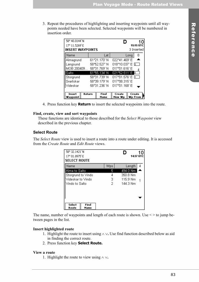
83
Re
fere
nc
ePlan Voyage Mode - Route Related Views
3. Repeat the procedures of highlighting and inserting waypoints until all way-points needed have been selected. Selected waypoints will be numbered in insertion order.
4. Press function key Return to insert the selected waypoints into the route.
Find, create, view and sort waypointsThese functions are identical to those described for the Select Waypoint view described in the previous chapter.
Select RouteThe Select Route view is used to insert a route into a route under editing. It is accessed from the Create Route and Edit Route views.
The name, number of waypoints and length of each route is shown. Use < > to jump be-tween pages in the list.
Insert highlighted route1. Highlight the route to insert using ∧ ∨. Use find function described below as aid
in finding the correct route.2. Press function key Select Route.
View a route1. Highlight the route to view using ∧ ∨.
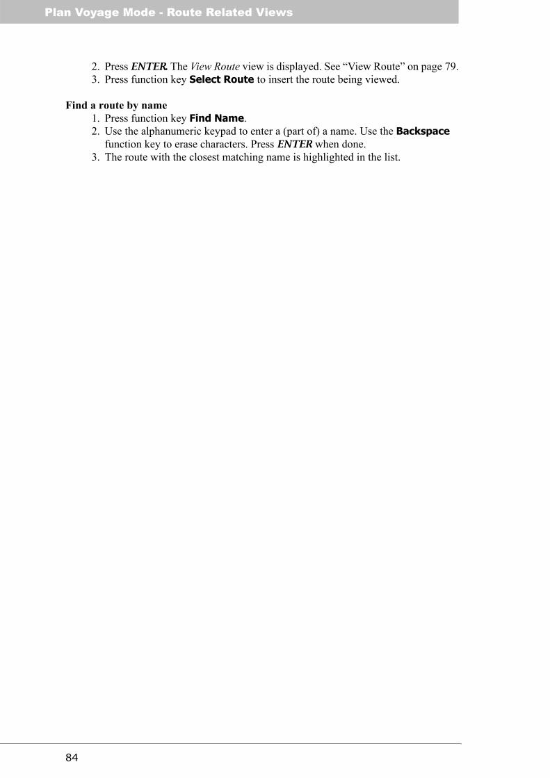
Plan Voyage Mode - Route Related Views
84
2. Press ENTER. The View Route view is displayed. See “View Route” on page 79.3. Press function key Select Route to insert the route being viewed.
Find a route by name1. Press function key Find Name.2. Use the alphanumeric keypad to enter a (part of) a name. Use the Backspace
function key to erase characters. Press ENTER when done.3. The route with the closest matching name is highlighted in the list.

85
Re
fere
nc
ePlan Voyage Mode - Waypoint List
Waypoint List
The Waypoint List view and subviews provides functionality to view, create, modify and delete waypoints. The list of waypoints can be sorted by name, time last modified and dis-tance, and the list can be search by specifying (part of) a waypoint name. Each waypoint is presented with its name and position.
Detailed information about each waypoint, including time of last modification, can be ac-cessed in the View Waypoint subview. The Edit Waypoint and Create Waypoint subviews are used to edit and create waypoints, respectively.
The view contains three pages of function keys, which can be shown by pressing the PAGE key one or multiple times. The first page is shown below.
The second and third pages of function keys are shown below.
Hint: Use < > to jump between pages of waypoints in the list.
Find waypoint by name1. Press function key Find Name.2. Use the alphanumeric keypad to enter (part of) a name. Use Backspace to
erase characters. Press ENTER when done.3. The waypoint with the closest matching name is highlighted in the list.
Edit a waypoint1. Select the waypoint to edit using ∧ ∨. Use the sort and find functions described
below as aid in finding the correct waypoint.2. Press function key Edit Waypoint.3. The Edit Waypoint view is displayed. See page 88.

Plan Voyage Mode - Waypoint List
86
Create a new waypoint1. Press function key Create New Wp.2. The Create Waypoint view is displayed. See page 90.
Create a new waypoint from an already existing waypoint1. Highlight the waypoint to use as base for the new waypoint in the list, using ∧
∨. Use the sort and find functions described below as aid in finding the correct waypoint.
2. Press function key Create Wp From.3. The Create Waypoint view is displayed, with position values taken from the
highlighted waypoint. See page 90.
Sail to a waypoint1. Highlight the desired waypoint using ∧ ∨. Use the sort and find functions
described below as aid in finding the correct waypoint.2. Press function key Sail To Wp.3. Bearing and distance to the selected waypoint is displayed. Confirm by pressing
function key Sail.
Sort waypoints by name, distance or time last modified1. Press function key Sort By Name, Sort By Distance or Sort By Time
depending on desired sorting criteria.
View waypoint1. Select the waypoint to edit using ∧ ∨. Use the sort and find functions described
below as aid in finding the correct waypoint.2. Press ENTER or function key View Waypoint.3. The View Waypoint view is displayed. See page 88.
Delete a waypoint1. Select the waypoint to edit using ∧ ∨. Use the sort and find functions described
below as aid in finding the correct waypoint.2. Press function key Delete Waypoint.3. Use < > to select Yes to the confirmation message and press ENTER, if you are
confident in deleting the waypoint.
Delete all waypoints1. Press function key Delete All Waypoints.2. If confident in deleting ALL waypoints and routes, use < > to select Yes to the
confirmation message. Press ENTER.
Note: All waypoints and routes will be permanently erased from the R4 Navigation Sys-tem!
Upload a waypoint from the R4 Navigation System to external system1. Highlight the waypoint to upload using ∧ ∨. Use the sort and find functions
described above as aid in finding the correct waypoint.2. Press function key Upload Waypoint. The waypoint will be transmitted to the
external system.

87
Re
fere
nc
ePlan Voyage Mode - Waypoint List
Upload all waypoints from the R4 Navigation System to external system1. Press function key Upload All Wps. All waypoints will be transmitted to the
external system.
In order for a waypoint transfer to occur, the output port connected to the external system must be configured with the NMEA WPL message enabled. See section “Transfer Way-points and Routes” on page 126 in the Appendix chapter for more information on upload-ing waypoints and routes.

Plan Voyage Mode - Waypoint Related Views
88
Waypoint Related Views
This section describes views used for viewing, editing and creating waypoints. Most of these views can be accessed from the Waypoint List view, but also from other views.
View WaypointThe view presents the full latitude and longitude values of a waypoint, its name as well as the time when the waypoint was last created or modified.
Edit WaypointThe Edit Waypoint view is used to modify an existing waypoint. Both name and position can be changed. The position can be modified by:
• Manually specifying latitude and longitude.• Taking latitude and longitude from current position.• Specifying a course and a distance to move the waypoint by.
If the edited waypoint is part of one or more existing routes, a warning dialog will be shown when entering the view (and also when saving changes), as illustrated below.
Press the function key Continue to edit the waypoint. Note that any changes made will affect all the routes that the waypoint is part of. To leave the other routes unmodified, press Cancel and create and use a new waypoint instead. Tip: Use the Create Wp From function key present in the Waypoint List and Select Waypoint views.

89
Re
fere
nc
ePlan Voyage Mode - Waypoint Related Views
The Edit Waypoint view is illustrated below.
The function key Apply and Exit is used to store changes made to the waypoint.
Change name of waypoint1. Select the Name field using ∧. Press ENTER.2. Use the alphanumeric keypad to enter name text, and the Backspace function
key to erase characters. Use function key Capslock to change between upper and lower case letters.
3. Press ENTER when done.
Modify latitude or longitude of waypoint1. Select the Lat or Long field using ∧ ∨. Press ENTER.2. Use < > to select the digit to modify, and enter the new digit using the alphanu-
meric keypad.3. Press ENTER when done.
Take waypoint position from current position1. Press function key Current Position.
Move waypoint by bearing and range1. Press function key Bearing/Range.2. The following view is shown.

Plan Voyage Mode - Waypoint Related Views
90
3. Use < to select the Bearing field. Press ENTER.4. Use the alphanumeric keypad to enter the bearing in degrees. Use Backspace
to erase digits. Press ENTER when done.5. Use > to select the Range field. Press ENTER.6. Use the alphanumeric keypad to enter a range. Use Backspace to erase digits.
Press ENTER when done.7. Press the function key Use Calculated to use the newly calculated position.
Create WaypointThe Create Waypoint view is used to create a new waypoint. The functions present in this view are the same as for the Edit Waypoint view. Refer to section “Edit Waypoint” on page 88 for detail.
This view can either by accessed by pressing the Create New Wp or Create Wp From function keys in the Waypoint List or Select Waypoint views. If accessed by pressing the Create New Wp function key, the position of the created waypoint is by default set to the current position. If accessed by pressing the Create Wp From function key, the po-sition is set to the position of currently highlighted waypoint in the waypoint list.
Press function key Apply and Exit to complete creating the waypoint.

91
Re
fere
nc
eAlarms & Msgs Mode - Overview
Alarms & Msgs Mode
The Alarms & Msgs mode is used to view the status of the R4 Navigation System. It con-tains views and functions for viewing current and past alarms, clearing the alarm log and reading DGPS messages. This mode also provides functionality for definition of time re-lated scheduled alerts.
To reach Alarms & Msgs mode, press MODE followed by function key ALARMS & MSGS. Press ESC one or a few times anywhere in the mode for access of top level func-tion keys.
Overview
The top level functions keys of the mode are illustrated below. Press ESC one or a few times anywhere in the mode to bring them up.
• Alarm List indicates which alarms that are active in the system. It also contains logs for viewing past and present alarms.
• DGPS Message lists all received DGPS messages, and supports reading and deleting them. The view is only present when using a R4 DGPS Navigation Sensor
• Scheduled Alerts provides access to functions for definition and inspection of time related alerts.
Below is a graphical overview of the different views present in Alarms & Msgs mode.

Alarms & Msgs Mode - Alarm List
92
The views are further described below. The DGPS Message view is only present when using a R4 DGPS Navigation Sensor.
Alarm List
The Alarm List view lists current status of all alarms. Active alarms are presented in the top of the list and are marked with an exclamation mark (!). The view contains the Alarm Log subview which shows the log of all alarms that has been activated in the system. In addition, it is possible to toggle between showing the enabled or the disabled alarms, by in each view pressing the function key Show Disabled. All alarms are described in sec-tion “Alarm Messages” on page 123 in the Appendix.
The Alarm List view is illustrated below.
View the log of all alarms1. Press function key Alarm Log.2. The following view is displayed. The view contains an entry for each time an
alarm has been active, and shows the time of activation and deactivation (if the alarm has been deactivated).
3. Press function key ESC to return to the main view.

93
Re
fere
nc
eAlarms & Msgs Mode - DGPS Message
Clear the alarm log1. Press function key Alarm Log. The above view is displayed.2. Press function key Clear Log. The alarm history will be erased.
DGPS Message
The DGPS Message view allows the user to read and delete received DGPS messages.
Note: The view is only present when using a R4 DGPS Navigation Sensor.
Read a received DGPS Message1. Highlight the message to read using ∧ ∨.2. The message body is displayed in the lower region of the view. If necessary,
press function key Read to see the entire message.
Delete a received DGPS Message1. Highlight the message to delete using ∧ ∨.2. Press function key Delete.
Scheduled Alerts
The Scheduled Alerts view allows the user to create and inspect alerts scheduled to acti-vate alarms at certain points in time.
There are two types of alerts that may be scheduled. Time Alerts are activated at a specific time and may be reactivated at a certain time interval. ETA Alerts will be activated at a certain time prior to ETA of the current active route.
When a scheduled alert is activated, it is treated like any other type of alarm in the system. Thus, the user may decide if scheduled alerts should be disabled, provide warning mes-sages on the display and/or generate external alarms. This is determined by settings in the Alarm Configuration view as described on page 105 of this manual.

Alarms & Msgs Mode - Scheduled Alert Related Views
94
The Scheduled Alerts view is illustrated below.
A list of the currently defined alerts is displayed together with the next (estimated) acti-vation time for each alert.
Create Time Alert1. Press function key Create Time Alert.2. The Create Time Alert view is displayed. See below.
Create ETA Alert1. Press function key Create ETA Alert.2. The Create ETA Alert view is displayed. See below.
Edit Scheduled Alert1. Highlight the alert to edit using ∧ ∨1. Press function key Edit Alert.2. The Edit Time Alert or Edit ETA Alert view is displayed. See below.
Delete Scheduled Alert1. Highlight the alert to delete using ∧ ∨.2. Press function key Delete Alert.3. A warning with request for confirmation is displayed. Press ENTER to delete
the alert.
View Scheduled Alert1. Highlight the alert to view using ∧ ∨.2. Press ENTER or function key View Alert.3. The View Time Alert or View ETA Alert view is displayed. See below
Scheduled Alert Related Views
This section describes views used for creating, editing and viewing scheduled alerts. These views are accessed from the Scheduled Alerts view.

95
Re
fere
nc
eAlarms & Msgs Mode - Scheduled Alert Related Views
Create Time AlertThe Create Time Alert view is used to create alerts that will be activated at specific times and repeated at certain time intervals. The view is illustrated below.
The function key Apply and Exit is used to store the alert settings when done.
Define alert text1. Select the Alert Text field using ∧ ∨, press ENTER.2. Use the alphanumeric keypad to enter text, and the Backspace function key to
erase characters. Use function key Capslock to change between upper and lower case letters. The text will be displayed when the alert is activated.
3. Press ENTER.
Define first activation time1. Select the Start Time field using ∧ ∨, press ENTER.2. Use the alphanumeric keypad to enter date and time when the alert is to be acti-
vated for the first time.3. Press ENTER.
Note: Time is entered in UTC or local time depending on the current time configuration of the system. Internally however, the alert start time will be converted to UTC. Thus, the alarm will be activated at the same UTC time regardless if the local time offset has been changed.
Define alert type and repetition interval1. Select the Type field using ∧ ∨, press ENTER.2. Select between Single (alert will be activated once) or Recurring (alert will be
reactivated at a certain interval) using ∧ ∨, press ENTER.3. If Recurring was selected, new fields for input of the repetition interval will be
displayed. Select the Hours field (if required) using ∧ ∨, press ENTER and enter the repetition interval in hours with the alphanumeric keypad.
4. Press ENTER.

Alarms & Msgs Mode - Scheduled Alert Related Views
96
5. Press > and enter a value in the Minutes field if required.
Create ETA AlertThe Create ETA Alert view is used to create alerts that will be activated at a specific time prior to ETA of the active route. The view is illustrated below.
The function key Apply and Exit is used to store the alert settings when done.
Define alert text1. Select the Alert Text field using ∧ ∨, press ENTER.2. Use the alphanumeric keypad to enter text, and the Backspace function key to
erase characters. Use function key Capslock to change between upper and lower case letters. The text will be displayed in the warning dialog on the dis-play when the alert is activated.
3. Press ENTER.
Define alert type1. Select the Type field using ∧ ∨, press ENTER.2. Select between Single (alert will be activated in the current or next active route
only) or Every Route using ∧ ∨, press ENTER.

97
Re
fere
nc
eAlarms & Msgs Mode - Scheduled Alert Related Views
Define activation time before ETA1. Select the Hours field using ∧ ∨, press ENTER.2. Enter the appropriate value through the alphanumeric keypad. Press ENTER.3. Press > and enter a value in the Minutes field if required.
Note: ETA alerts will be activated once in every route only. Thus, the alert will not reac-tivate if the time before ETA criterion will be fulfilled duplicate times due to variations in speed.
Edit Time AlertThe Edit Time Alert view is used to change settings for a specific time alert. The view is identical to the Create Time Alert view described above, with the edited alert settings en-tered.
Edit ETA AlertThe Edit ETA Alert view is used to change settings for a specific ETA alert. The view is identical to the Create ETA Alert view described above, with the edited alert settings en-tered.
View Time AlertThe View Time Alert view is used to view the settings for a specific time alert. The view is identical to the Edit Time Alert view described above, except that contents not can be edited and with the function key Apply and Exit replaced by Edit. Press the Edit func-tion key to access the Edit Time Alert view if necessary.
View ETA AlertThe View ETA Alert view is used to view settings for a specific ETA alert. The view is identical to the Edit ETA Alert view described above, except that contents not can be ed-ited and with the function key Apply and Exit replaced by Edit. Press the Edit function key to access the Edit ETA Alert view if necessary.

Alarms & Msgs Mode - Scheduled Alert Related Views
98
This page is intentionally empty.

99
Re
fere
nc
eConfig Mode - Overview
Config Mode
The Config mode is used to configure the R4 Navigation System. To get to the Config views, press MODE followed by function key CONFIG. Press ESC one or a few times anywhere in the mode for access of top level function keys.
Overview
Use the PAGE key to toggle between the pages of top level function keys.
The main views of Config mode are introduced below.
• Time allows the user to define a local time offset from UTC and choose if dis-played time values shall be in local or UTC time frames.
• Display Config allows the user to configure settings for the R4 Display, both visual and sound settings.
• Nav Config allows the user to configure navigation parameters.• Alarm Config allows the user to configure which alarms that should be used and
if they should trigger the external alarm signal.• Units Config allows the user to configure the used units.• GPS/DGPS Config allows the user to configure GPS, DGPS, Beacon and SBAS
settings.• Redund Config allows the user to configure the system to interact with another
R4 nav system in order to synchronize database and settings between the units.• I/O Config allows the user to configure input and output sentences and port
communication rates.• System Info allows the user to view current system information including soft-
ware and hardware versions as well as memory usage.
First Page
Second Page

Config Mode - Overview
100
Below is a graphical overview of the different views present in the mode.
Note: The Beacon Config and Beacon Database view with subviews are only present when using the R4 DGPS Navigation Sensor.
The views are further described below.

101
Re
fere
nc
eConfig Mode - Time Config
Time Config
The Time Configuration view is used to define a local time offset from UTC and to select whether displayed time values shall be in local or UTC time frames. The Time Configu-ration view is illustrated below.
Change local time offset1. Edit the +/- field if required by selecting it using < > and press ENTER. Use ∧ ∨
to set the desired sign and press ENTER again.2. Edit the hours field if required by selecting it using < > and press ENTER. Use
the numeric keyboard together with function key Backspace to enter the desired value. Press ENTER when done.
3. Repeat the procedure to edit the minutes field if required.
Select time frame for display1. Press function key Use UTC to display all times in UTC. Press function key
Use Local to display all times with the current local offset from UTC. This will be indicated by ‘LOC’ displayed after the time values instead of ‘UTC’.
Note: Values of time output on the serial interface will always be in UTC regardless of display time configuration.

Config Mode - Display Config
102
Display Config
The Display Configuration view contains two subviews, the Visual Configuration and Sound Configuration views. The former is used to configure display illumination settings and the latter the sounds played at different events.
Visual ConfigThe Visual Configuration view allows the user to adjust display back light, contrast, LED intensity and button illumination. Two separate settings are provided, for day and for night operation.
Change display setting1. Select Day Settings or Night Settings with < >.2. Select the setting you want to change using ∧ ∨ and press ENTER.3. Modify the setting with < > and press ENTER. Repeat step 1 to 3 if necessary.4. Press function key Apply and Exit.
Note: As described in section “Visual Settings” on page 34, it is also possible to change visual settings by pressing the DISPLAY key.

103
Re
fere
nc
eConfig Mode - Nav Config
Sound ConfigThe Sound Configuration view allows the user to associate an event with a specific sound. The settings can be restored to their default values.
Change settings1. Select the setting you want to change using ∧ ∨ and press ENTER.2. Select the desired value in the drop-down list using ∧ ∨, and press ENTER.3. Press function key Apply and Exit.
Restore a parameter to factory default setting1. Use ∧ ∨ to select the parameter to return to the factory default setting.2. Press function key Get Default.3. Press function key Apply and Exit to save the changes.
Nav Config
The Navigation Configuration view is used to configure navigation parameters including navigation algorithm, waypoint pass criterion, range unit, waypoint change distance (for “distance” waypoint pass criterion), cross-track error alarm limit and waypoint approach alarm distance or time. The parameters are described below.
Wp Pass CriterionThe Waypoint Pass Criterion parameter specifies the method used to determine when a waypoint is considered passed. The parameter can be set to one of Manual, Distance, Bi-sector Line or Perpendicular Line. The different waypoint pass criteria are described in chapter “Concepts and Terminology” on page 9.
Wp Pass DistanceThe Waypoint Pass Distance parameter specifies the distance to the waypoint where it is considered passed when using the Distance waypoint pass criteria.
Default RAIMThis field sets the default RAIM accuracy level to appear when specifying a RAIM accu-racy level for a leg in a route. See section “RAIM Accuracy Level” on page 16 for more information.

Config Mode - Nav Config
104
Navigation AlgorithmThe Navigation Algorithm parameter specifies the default navigation algorithm for newly created legs. The algorithm can either be set to Rhumb Line or Great Circle. The differ-ence between these algorithms are described in chapter “Concepts and Terminology” on page 9. This parameter also determines the navigation algorithm used when sailing to-wards the first waypoint in a route or towards a single waypoint.
XTE LimitThe Cross-Track Limit parameter specifies the cross-track error limit used when navigat-ing. If the cross-track error becomes larger than the set XTE Limit, the XTE Limit Exceed-ed alarm is raised and remains active until the cross-track error becomes less then the set XTE Limit, or navigation along the active route stops.
Approach DistanceThe Approach Distance parameter specifies the distance from next waypoint where the Waypoint Approaching (Distance) alarm is raised.
Approach TimeThe Approach Time parameter specifies the estimated time (in minutes) before arrival to the next waypoint when the Waypoint Approaching (Time) alarm is raised.
RTE Nav AlgorithmThe RTE Navigation Algorithm specifies the navigation algorithm that is set for routes re-ceived from external systems, for example from ECDIS systems. See section “Download Waypoints and Routes” on page 126 in the Appendix chapter for more information.
Average SOG TimeThe Average ETA SOG parameter defines the time period over which average speed is cal-culated when estimating time of arrival (ETA) to the end of the active route and Time To Go (TTG) to the next waypoint.
Status InformationThe Status Information parameter defines whether current position (when available) or the name of the next waypoint is to be displayed in the status bar at the upper left corner of the display.
The Navigation Configuration view is illustrated below.

105
Re
fere
nc
eConfig Mode - Alarm Config
Change a parameter1. Select the parameter to edit using ∧ ∨ and press ENTER.2. If the parameter is selected using a drop-down box, use ∧ ∨ to select the desired
option in the drop-down box.If the parameter is a numeric value, use the alphanumeric keypad to enter the desired value. Use the Backspace function key to erase digits.
3. Press ENTER when done.4. Press function key Apply and Exit to save the changes.
Restore factory default setting1. Use ∧ ∨ to select the parameter to return to the factory default setting.2. Press function key Get Default.3. Press Apply and Exit to save the changes.
Alarm Config
The Alarm Configuration view is used to configure the action the system should perform when a specific alarm is raised. The possible settings for each alarm are:
• Disabled. The alarm will not be indicated when active.• Popup. An alarm pop-up will be displayed when the alarm becomes active. See
section “Alarm Pop-ups” on page 41.• External. The Alarm Output signal will be activated when the alarm is active,
typically triggering a visual alarm indicator and/or alarm bell. This setting will also generate alarm messages on the serial interface provided that the NMEA ALR message has been enabled on the specific port.
• Popup & External. The alarm will result in both an alarm pop-up dialog and external alarm signal being activated.
It is possible to disable alarms that are of no interest for the operator by setting them to Disabled.
In this view it is also possible to enable and disable the use of an external alarm acknowl-edge momentary switch for acknowledging alarms. This is controlled by the Allow Exter-nal Ack parameter. An external acknowledge input signal will acknowledge all active alarms.
Specific external navigation alarms may be acknowledged through the serial interface us-ing the NMEA ‘ACK’ sentence.

Config Mode - Units Config
106
Change setting1. Use ∧ ∨ to select the parameter to modify and press ENTER.2. Select the desired value in the drop-down list using ∧ ∨, and press ENTER.3. Press function key Apply and Exit to save the changes.
Restore factory default setting1. Use ∧ ∨ to select the parameter to return to the factory default setting.2. Press function key Get Default.3. Press function key Apply and Exit to save the changes.
Units Config
The Units Configuration view is used to configure used units of measurements in the sys-tem. The configurable types of units are described below.
Range UnitThe unit used when displaying range values. Can be set to one of Nautical Mile, Kilom-eters and Statute Mile.
Speed UnitThe unit used when displaying speed values. Can be set to one of Knots, kilometers per hour (km/h) and miles per hour (mph).
Depth UnitThe unit used for displaying depth. Can be set to one of meters, feet or fathoms.
Anchor Range UnitThe unit used to specify and display the alarm limit and current range to reference position in the Anchor Watch views. Can be set to one of meters or feet.
Note: RAIM accuracy level is always input and displayed in meters regardless of selected units.

107
Re
fere
nc
eConfig Mode - GPS/DGPS Config
Change setting1. Use ∧ ∨ to select the parameter to modify and press ENTER.2. Select the desired value in the drop-down list using ∧ ∨, and press ENTER.3. Press function key Apply and Exit to save the changes.
Restore factory default setting1. Use ∧ ∨ to select the parameter to return to the factory default setting.2. Press function key Get Default.3. Press function key Apply and Exit to save the changes.
GPS/DGPS Config
The view contains the GPS Configuration and SBAS Configuration subviews. When an R4 DGPS Navigation Sensor is used, the view will also include the Beacon Configuration and Beacon Database subwievs. The views are used to configure GPS, SBAS and Beacon settings of the R4 Navigation Sensor.
GPS ConfigThe GPS Configuration view allows the user to configure current GPS settings of the R4 Navigation Sensor. The following fields can be changed.
Elevation MaskThis parameter sets the elevation cutoff mask angle, in degrees, for the GPS. Any satel-lites below this mask angle will be ignored, even if available. The value should be be-tween 0 and 60 degrees, and the default value is 5 degrees.
Correction AgeThis field sets the maximum allowed age (in seconds) for correction data. The R4 Navi-gation Sensor is able to use old correction data for extended periods of time. The default setting is 120 seconds. The lowest allowed value is 10 seconds and the highest 900 sec-onds. When increasing the allowed correction age, ensure that the new setting meets your requirements as accuracy will degrade with increasing correction age.

Config Mode - GPS/DGPS Config
108
Correction SourceThis parameter sets the source for differential corrections. Valid settings are:
• Beacon. In this setting the system will use signals from IALA radio beacon sta-tions as source for differential corrections. This setting is only available when using an R4 DGPS Navigation Sensor (the DGPS configuration).
• SBAS. This setting makes the system use SBAS satellite signals as source for differential corrections.
• User Port 1. This setting will command the system to apply external differential corrections received in RTCM SC-104 format on the User 1 port. The User 1 port will not be available for output of serial data from the system if this setting is selected.
• None. This setting makes the system operate in autonomous mode, not using any differential corrections.
ATTENTION: Both the EGNOS and MSAS satellite based augmentation systems (SBAS) are currently under development. Signals from these systems are there-fore used entirely at your own risk.
SOG Smoothing ParameterThe SOG Smoothing parameter allows you to adjust the level of responsiveness of the speed over ground (SOG) measurement, as displayed by the R4 Display and provided in the $GPVTG and $GPRMC sentences. The default value is zero, and increasing the value will increase the level of SOG smoothing.
The setting of this parameter depends upon the expected dynamics of the vessel. If a ship is highly dynamic, this value should be set to a lower value since the filtering window needs be shorter in time, resulting in a more responsive measurement. However, if a ves-sel is very large and has much more resistance to change in its motion, this value can be increased to reduce measurement noise. The following formula provides some guidance on how to set this value. If unsure on which value to set, it's best to be conservative and leave this parameter at the default setting of 0.0 seconds.
SOG smoothing = 10 / maximum acceleration (in m/s²)
COG Smoothing ParameterThe COG Smoothing parameter allows you to adjust the level of responsiveness of the course over ground (COG) measurement, as displayed by the R4 Display and provided in the $GPVTG and $GPRMC sentences. The default value is zero, and increasing the value will increase the level of COG smoothing. As with the SOG smoothing parameter, the setting of this parameter depends upon the ex-pected dynamics of the vessel. If a ship is highly dynamic, this value should be set to a lower value since the filtering window needs be shorter in time, resulting in a more re-sponsive measurement. However, if a vessel is very large and has much more resistance to change in its motion, this value can be increased to reduce measurement noise. The fol-lowing formula provides some guidance on how to set this value initially. It is however recommended that you test how the revised value works in practice. If unsure on which value to set, it's best to be conservative and leave this parameter at the default setting of 0.0 seconds.
COG smoothing = 10 / maximum rate of change in course (in °/s)

109
Re
fere
nc
eConfig Mode - GPS/DGPS Config
Note: The ship needs to be moving to calculate a valid COG value. Do not use COG val-ues output while the ship is at rest as a basis for adjusting this parameter.
The GPS Configuration view is illustrated below.
Change setting1. Select the parameter to edit using ∧ ∨ and press ENTER.2. If the parameter is selected using a drop-down box, use ∧ ∨ to select the desired
option in the drop-down box.If the parameter is a numeric value, use the alphanumeric keypad to enter the desired value. Use the Backspace function key to erase digits.
3. Press ENTER when the correct parameter value has been entered.4. Press function key Apply and Exit.
Restore factory default setting1. Use ∧ ∨ to select the parameter to return to the factory default setting.2. Press function key Get Default.3. Press function key Apply and Exit to save the changes.
Beacon ConfigThe Beacon Configuration view is used to configure beacon receiver parameters of the R4 DGPS Navigation Sensor. This includes setting the frequency and bit rate mode, as well as the radiobeacon frequency and bit rate if manual mode is used.
Note: The Beacon Configuration view is only present when using a R4 DGPS Navigation Sensor.
Tuning ModeThe Tuning Mode parameter sets the frequency selection mode of the R4 DGPS Naviga-tion Sensor internal radio beacon receiver. The mode can be either Frequency Scan or Manual. In Frequency Scan mode, the beacon receiver will search available frequencies and tune to the strongest beacon signal. In this mode, the R4 Navigation Sensor continu-ously performs background search to discover higher quality DGPS signals. While per-forming background searches, the R4 Navigation Sensor continues to receive differential corrections from the current radiobeacon station.

Config Mode - GPS/DGPS Config
110
In Manual tuning mode, the R4 DGPS Navigation Sensor tunes to the specified beacon frequency for receiving DGPS signals.
FrequencyThe Frequency parameter is used to set the frequency to use for receiving DGPS signals, when the frequency mode parameter is set to manual. Valid frequencies are between 283.5 and 325 KHz, at 0.5 kHz intervals.
Bit Rate ModeThe Bit Rate Mode parameter sets the bit rate mode, to either Automatic or Manual. In Automatic mode the R4 DGPS Navigation Sensor will automatically select the correct bit rate to use for demodulating the radio beacon signal. In Manual mode, the R4 DGPS Nav-igation Sensor will use the specified bit rate.
Bit RateThe Bit Rate parameter is used to set the bit rate used for demodulation of the DGPS sig-nal, when using the manual bit rate mode. The bit rate can be set to one of 50, 100 and 200 bps.
Change Tuning Mode, Bit Rate Mode or Bit Rate1. Select the parameter to edit using ∧ ∨ and press ENTER.2. Use ∧ ∨ to select the desired mode in the drop-down box and press ENTER.3. Press function key Apply and Exit.
Change Frequency1. Select the parameter using ∧ ∨ and press ENTER.2. Use the alphanumeric keyboard enter the desired value. Use the Backspace
function key to erase digits. Press ENTER when done.3. Press function key Apply and Exit.
Restore factory default setting1. Use ∧ ∨ to select the parameter to return to the factory default setting.2. Press function key Get Default.3. Press function key Apply and Exit to save the changes.

111
Re
fere
nc
eConfig Mode - GPS/DGPS Config
SBAS ConfigThe SBAS Configuration view is used for control of SBAS satellite tracking for the two dedicated SBAS channels of the R4 Navigation sensor.
With the PRN Search Mode parameter, search mode can be set to either Automatic or Manual.
In Manual search mode, the R4 Navigation sensor will try to acquire signals from satel-lites with id (PRN) numbers input by the parameters PRN 1 and PRN 2 in the view. If only one particular satellite is to be tracked, input same number for both parameters.
In Automatic search mode, the R4 Navigation Sensor will try to identify and track SBAS signals without user control of satellite selection.

Config Mode - Redund Config
112
Redund Config
The Redundant System Configuration view is to be used in a redundant system configu-ration where two interconnected R4 navigation systems automatically synchronize their internal data bases and some settings.
The systems to be synchronized are to be interconnected by their User 3 serial ports‘. These ports are thus not available for other purposes in this configuration.
During synchronized operation, any changes to a synchronized item performed by the user at one system will also be incorporated in the other system. This applies regardless if the change is made through a manual input or by the serial interface.
It is the responsibility of the user not to input conflicting information to the two systems, such as different waypoints with identical names. The general rule is that the last change will override any previous inputs in such a case.
The following items are synchronized:
• Waypoints• Routes• Active Route• XTE reset function• MOB function• RAIM setting• Target ETA• Waypoint pass criterion (Nav Config)• Waypoint pass distance (Nav Config)• Default RAIM value (Nav Config)• Nav Algorithm (Nav Config)• XTE limit (Nav Config)• Approach distance (Nav Config)• Default nav algorithm for received routes (Nav Config)• Averaging time for SOG used in ETA and TTG calculations (Nav Config)
The Redundant System Configuration view is illustrated below.

113
Re
fere
nc
eConfig Mode - Redund Config
The Mode parameter can be set to Disabled (default), Master or Slave. When redundant configuration not is to be used, the parameter shall be set to Disabled. In a redundant con-figuration, one unit shall be set to Master and the other unit to Slave. Press function key Apply and Exit to save the changes.
When the Mode parameter is set to anything but Disabled, communication with an exter-nal unit is to be expected. Current status of redundant operation is indicated by icons in the status bar at the top of the display as follows:
Redundant operation active Redundant operation active. Synchronizing from external unit. Redundant configuration has been enabled but no communication is established.
When initial contact is established between two units their internal contents are compared. If they are different, a warning will be displayed as illustrated below.
Select which unit to perform initial synchronization to or use the Later option to perform any desired changes before synchronization begins. In the latter case, function keys Synch This and Synch Remote will be available in the Redundant System Configura-tion view.
Note 1: At the initial synchronization, all contents in both systems will be set equal to the contents of the system that synchronization is made from. Unique contents of the other (receiving) system will be erased.
Note 2: During the initial synchronization process, the receiving unit (as indicated by the icon) will have a large numbers of its functions temporarily disabled. For instance, any
active route or active MOB function will be terminated and any attempts to modify the route/waypoint database (either by manual inputs or by the serial interface) will be reject-ed.
Once initial synchronization is performed, changes to synchronized items will be applied to both systems automatically without the need for special actions by the operator.

Config Mode - I/O Config
114
I/O Config
The I/O Configuration view contains three subviews, used to configure the used input sentences, transmitted output sentences and port speed settings. The subviews are Input Config, Output Config and the Port Rate Config. The Port Rate Config view also contains functionality for viewing the data received on the ports (suitable for troubleshooting).
Input ConfigThe Port Input Configuration view contains subviews for specification of sentences that shall be interpreted and used for navigation. It is possible to define sentences to use for sensor data (heading and depth) and for receiving waypoint and route information. For each type of data, the used sentences can be limited in the following ways:
Input PortThis parameter makes it possible to only use sentences received on a particular port for the type of data.
Input SentenceThis parameter makes it possible to only use a specific NMEA sentence for the type of data.
Input Talker IDThis parameter makes it possible to only use sentences from a specific talker (having a specific NMEA talker ID) for the type of data.
The Port Input Configuration view is illustrated below.
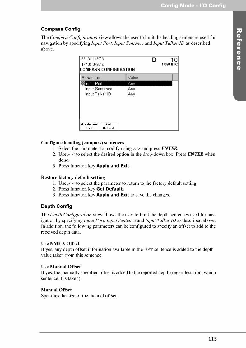
115
Re
fere
nc
eConfig Mode - I/O Config
Compass ConfigThe Compass Configuration view allows the user to limit the heading sentences used for navigation by specifying Input Port, Input Sentence and Input Talker ID as described above.
Configure heading (compass) sentences1. Select the parameter to modify using ∧ ∨ and press ENTER.2. Use ∧ ∨ to select the desired option in the drop-down box. Press ENTER when
done.3. Press function key Apply and Exit.
Restore factory default setting1. Use ∧ ∨ to select the parameter to return to the factory default setting.2. Press function key Get Default.3. Press function key Apply and Exit to save the changes.
Depth ConfigThe Depth Configuration view allows the user to limit the depth sentences used for nav-igation by specifying Input Port, Input Sentence and Input Talker ID as described above. In addition, the following parameters can be configured to specify an offset to add to the received depth data.
Use NMEA OffsetIf yes, any depth offset information available in the DPT sentence is added to the depth value taken from this sentence.
Use Manual OffsetIf yes, the manually specified offset is added to the reported depth (regardless from which sentence it is taken).
Manual OffsetSpecifies the size of the manual offset.
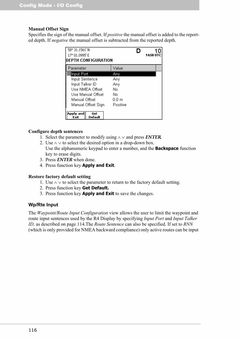
Config Mode - I/O Config
116
Manual Offset SignSpecifies the sign of the manual offset. If positive the manual offset is added to the report-ed depth. If negative the manual offset is subtracted from the reported depth.
Configure depth sentences1. Select the parameter to modify using ∧ ∨ and press ENTER.2. Use ∧ ∨ to select the desired option in a drop-down box.
Use the alphanumeric keypad to enter a number, and the Backspace function key to erase digits.
3. Press ENTER when done.4. Press function key Apply and Exit.
Restore factory default setting1. Use ∧ ∨ to select the parameter to return to the factory default setting.2. Press function key Get Default.3. Press function key Apply and Exit to save the changes.
Wp/Rte InputThe Waypoint/Route Input Configuration view allows the user to limit the waypoint and route input sentences used by the R4 Display by specifying Input Port and Input Talker ID, as described on page 114.The Route Sentence can also be specified. If set to RNN (which is only provided for NMEA backward compliance) only active routes can be input

117
Re
fere
nc
eConfig Mode - I/O Config
to the system. See appendix “Transfer Waypoints and Routes” on page 126 for more de-tails.
Configure used waypoint and route sentences1. Select the parameter to modify using ∧ ∨ and press ENTER.2. Use ∧ ∨ to select the desired option in the drop-down box. Press ENTER when
done.3. Press function key Apply and Exit.
Restore factory default setting1. Use ∧ ∨ to select the parameter to return to the factory default setting.2. Press function key Get Default.3. Press function key Apply and Exit to save the changes.
Output ConfigThe Port Output Configuration view is used to configure which sentences are output on the User Ports of the R4 Navigation System, and how often they are sent. In the Output Configuration subview for each user port, current load on the port is displayed. This gives an indication on how much of the port’s baud rate that is used up by the enabled sentences. Only turn on the sentences that you intend to use.
If no response is received from the R4 Navigation Sensor, the R4 Navigation Sensor de-pendant sentences will be locked.
For a list of output sentences available on the different serial ports, refer to the R4 Navi-gation System installation manual (p/n 7000 109-142).

Config Mode - Port Rate Config
118
The Port Output Configuration view is illustrated below.
Modify sentences sent on a specific port1. Press the function key corresponding to the port to modify output sentences for.
The following view is displayed.
2. Highlight the sentence to modify output for using ∧ ∨.3. To set the output interval, press ENTER and use ∧ ∨ to select the desired fre-
quency to output the sentence at, or select Disabled to disable output of the selected sentence. Press ENTER when done.Press the function key Get Default to set the output interval to the factory default setting.
4. Repeat step 3 and 4 for each sentence to modify.5. Press function key Apply and Exit when done.
Port Rate Config
The Port Rate Configuration view allows the user to configure the communication rate used for the serial ports in the R4 Navigation System, and the output rate of the Speed Log Output binary port. The view also makes it possible to view the data that is received on the different serial ports.
The rate for the Speed Log Output binary port can be set to one of Disabled, 100, 200, 300 or 400 pulses per nautical mile (P/Nm). The default setting is that Speed Log output is dis-

119
Re
fere
nc
eConfig Mode - Port Rate Config
abled. The output pulse period has a resolution of 50 ms providing a resolution of 0.5 knots up to 10-20 knots depending on pulse rate with a working range up to 30 knots.
The communication rate for User port 1 and 2 are locked if no response is received from the R4 Navigation Sensor.
Change communication rate1. Select port to change communication rate (baud rate) for using ∧ ∨ and press
ENTER.2. Use ∧ ∨ to select the desired communication rate in the drop-down box and
press ENTER.3. Press function key Apply and Exit.
Change Speed Log output rate1. Select the Speed Log Output parameter using ∧ ∨. Press ENTER.2. Use ∧ ∨ to select the desired speed log output frequency in the drop-down list.
Press ENTER when done.3. Press function key Apply and Exit when done.
Restore factory default setting1. Use ∧ ∨ to select the port to return to the factory default setting.2. Press function key Get Default.3. Press function key Apply and Exit to save the changes.

Config Mode - Port Rate Config
120
View received data1. Select serial port to view received data on using ∧ ∨. It is not possible to view
received data on User Port 2, as it only supports output data.2. Press function key View Raw Data. The following view is displayed.
3. Use function key Freeze to stop the update of raw data on the screen. Use Resume function key to view more data.
4. Press ESC when done.

121
Re
fere
nc
eConfig Mode - System Info
System Info
The System Information view provides subviews for general system information. It con-tains subviews for: viewing software and hardware versions, displaying the results of the R4 Display’s last performed built-in integrity tests and for viewing the current memory usage of the R4 Display.
View software and hardware versions1. Press the function key SW/HW Versions.2. The below view is displayed.
The view shows the software versions of the different components present in the R4 Dis-play and R4 Navigation Sensor as well as the display’s hardware revision and GPS mod-ule serial number. The current system configuration—GPS or DGPS—is also indicated at the top of the screen.
View the result of the R4 Display’s last performed built-in integrity tests1. Press function key Display BIIT Info.2. A view displaying the built in test result is shown, as illustrated below.

Config Mode - System Info
122
View current memory usage of the R4 Display1. Press function key Memory Usage.2. The Memory Usage view is shown, as illustrated below.
The memory usage is measured for:• Route Database percentage of number of routes used• Waypoints in Routes percentage of route storage used• Waypoint Database percentage of waypoint storage used• MoB Waypoints percentage of MOB waypoint storage used• DGPS Message percentage of DGPS message storage used

123
Ap
pe
nd
ixAlarm Messages
Appendix
Alarm Messages
The alarm messages that can occur in a R4 Navigation System are listed below.
Navigation Alarms Description
NAV: HDOP Limit ExceededThis alarm is active when the HDOP (horizontal dilution of precision) exceeds 4.0.
NAV: Position Data LostThis alarm is active when no valid position information is available from the R4 Naviga-tion Sensor.
NAV: DGPS Position Data LostThis alarm is active when a differentially corrected position is not available.
NAV: GPS Not InitializedThe alarm is active when the display is not able to configure or receive the current con-figuration from the R4 Navigation Sensor.
Table 1: Navigation Alarm Messages
ID Message151 NAV: HDOP Limit Exceeded152 NAV: Position Data Lost153 NAV: DGPS Position Data Lost154 NAV: GPS Not Initialized155 NAV: GPS Connection Lost156 NAV: XTE Limit Exceeded157 NAV: Approaching Waypoint (Distance)170 NAV: Approaching Waypoint (Time)159 NAV: Serial Waypoint Download Failed160 NAV: Serial Route Download Failed161 NAV: Heading Data Lost162 NAV: Depth Data Lost163 NAV: RAIM Status - Caution164 NAV: RAIM Status - Unsafe166 NAV: Redundant System Connection Lost167 NAV: Anchor Alarm Distance Exceeded168 NAV: Scheduled Alert169 NAV: DGPS Integrity Alert

Alarm Messages
124
NAV: GPS Connection LostThis alarm is active if the communication between the GPS and the display unit does not work.
NAV: XTE Limit ExceededThis alarm is active if the current cross-track error is greater than the configured cross-track error limit.
NAV: Approaching Waypoint (Distance)This alarm is active when the distance to next waypoint is shorter than the approach dis-tance configured in the Nav Config view, described on page 103.
NAV: Approaching Waypoint (Time)This alarm is active when the estimated time to go to next waypoint is shorter than the waypoint approach time configured in the Nav Config view, described on page 103.
NAV: Serial Waypoint Download FailedThis alarm is raised if serial download of waypoint information has failed.
NAV: Serial Route Download FailedThis alarm is raised if serial download of route information has failed.
NAV: Heading Data LostThis alarm is active when no valid heading data is received.
NAV: Depth Data LostThis alarm is active when no valid depth data is received.
NAV: RAIM Status - CautionThis alarm is active when the RAIM status is caution.
NAV: RAIM Status - UnsafeThis alarm is active when the RAIM status is unsafe.
NAV: Redundant System Connection LostNo connection to an external R4 nav system in redundant system configuration.
NAV: Anchor Alarm Distance ExceededThis alarm is active when the anchor watch function is in operation and the range limit has been exceeded.
NAV: Scheduled AlertThis alarm is active when a scheduled time or ETA alert has been activated.
NAV: DGPS Integrity AlertThis alarm is active when any of the following conditions apply:
• No DGPS Signal: A correction source for GPS other than None has been selected in the GPS Configuration view and more than ten seconds have passed since a new set of differential corrections were applied to the navigation solu-tion.

125
Ap
pe
nd
ixAlarm Messages
• Station Unhealthy: Beacon has been selected as correction source for GPS and the radio beacon station in use indicates an unhealthy status.
• Station Unmonitored: Beacon has been selected as correction source for GPS and the radio beacon station in use indicates an unmonitored status.
• Poor Signal: Beacon has been selected as correction source for GPS and word error rate of the received signal in use exceeds 10%.

Transfer Waypoints and Routes
126
Transfer Waypoints and Routes
The R4 Navigation System supports both download and upload of waypoints and routes from/to ECDIS and other external systems. The system also support continuous output of the current active route. Waypoints and routes are transferred using the WPL and RTE sen-tences. The WPL and RTE sentences are interpreted according to the IEC 61162-1 (2000) standard. The Rnn sentence is supported but for NMEA backward compliance only. It can only be used to output and receive active routes.
Download Waypoints and Routes
Waypoints and complete routes can be received on both user port 1 and 3, using the WPL and RTE sentences. Active route can also be received using the Rnn sentence. Which sen-tences that should be interpreted can be configured in the Wp/Rte Input view, described on page 116.
Received routes are assigned the navigation algorithm specified by the parameter RTE Nav Algorithm, described in section “Nav Config” on page 103. The R4 Navigation Sys-tem can store a maximum of 2000 waypoints and 100 routes.
Waypoint and Complete Route DownloadsReceived waypoints and complete routes will be stored in the R4 Display, and will auto-matically replace any existing waypoints/routes with the same name.
Working Route DownloadsA working route—indicated by the Message mode field being set to ‘w’ in the RTE sen-tence— that is received by the R4 Navigation System will automatically become the new active route of the system, and replace any existing active route.
Routes received using the Rnn sentence will also automatically become the new active route. The ‘nn’ part of the Rnn sentence is interpreted in the same way as the Route iden-tifier field of the RTE sentence, i.e. as route name.
The first received waypoint of a working route will become the first ‘from’ waypoint and the second waypoint received will become the first ‘to’ waypoint of the active route. This is in accordance with the interpretation of the RTE sentence for working routes as defined in IEC standard 61162-1.
Upload Waypoints and Complete Routes
Uploaded waypoints and routes will be output using the WPL and RTE sentences, on the serial port where the sentence WPL/RTE Upload is enabled. See section “Output Con-fig” on page 117 for details on enabling output sentences.
To upload a waypoint, go to the Waypoint List view—described on page 85—and use the Upload Waypoint function key to transmit information about the highlighted waypoint on the configured serial port(s). It is also possible to upload the complete set of waypoints with a function key labelled Upload All Wps. To upload a complete route, go to the Route List view—described on page 71—and use the Upload Route function key to transmit information about the highlighted route and all associated waypoints.

127
Ap
pe
nd
ixTransfer Waypoints and Routes
Output Working Route and Remaining Waypoints
The system supports output of the current active route (the working route) and the remain-ing waypoints of the route. The active route can be transmitted both using WPL/RTE and WPL/RNN sentences. Usage of WPL/RTE is recommended.
When navigating towards the first waypoint of the route, the ship’s current position is out-put as the origin waypoint. This waypoint is named “t0” when using WPL/RTE and “0000” when using WPL/RNN.
When transmitting active route data using WPL/RNN, the waypoints in the active route are given a number corresponding to their position in the route, starting from “0001”. The “NN” field in RNN is always “00”
Currently, the active route output is limited to include only the next four remaining way-points of the route. This is implemented to avoid unnecessary clutter for instance when the route is plotted on radar displays
Enabling output sentences is described in section “Output Config” on page 117.

Transfer Waypoints and Routes
128
This page is intentionally empty.

129
Glo
ss
ary
Glossary
BRG . . . . . Bearing
COG. . . . . Course Over Ground
DGNSS . . Differential Global Navigational Satellite System
DPT . . . . . Depth
ECDIS . . . Electronic Chart Display and Information System
EGNOS . . European Geostationary Navigation Overlay Service
ETA . . . . . Estimated Time of Arrival
GNSS . . . . Global Navigational Satellite System
GPS . . . . . Global Positioning System
HDG. . . . . Heading
HDOP. . . . Horizontal Dilution Of Precision
IALA . . . . International Association of Lighthouse Authorities
IEC. . . . . . International Electrotechnical Commission
IMO . . . . . International Maritime Organization
MSAS. . . . MTSAT Satellite Augmentation System (Japan)
NMEA . . . National Marine Electronics Association
RAIM. . . . Receiver Autonomous Integrity Monitoring
RNG. . . . . Range
ROT . . . . . Rate Of Turn
Rte . . . . . . Route
Rx. . . . . . . Receive
SBAS . . . . Satellite Based Augmentation System
SNR . . . . . Signal to Noise Ratio
SOG . . . . . Speed Over Ground

130
TIW . . . . . Time In Water
TTG . . . . . Time To Go
Tx . . . . . . Transmit
UTC. . . . . Universal Time Coordinated
WAAS . . . Wide Area Augmentation System (United States)
WCV . . . . Waypoint Closure Velocity
WP. . . . . . Waypoint

131
Ind
ex
Index
AActive Route 9, 53Alarm 32, 123Alarm Configuration 105Alarm List 32, 92Alarm Messages 123Alarms And Messages mode 91Alphanumeric Keys 11Anchor Watch 65Approach Alarm Distance 104
BBeacon Configuration 109Beacon Station Database 111Beacon Status 47Beacon Tuning Mode 46, 47, 109Bit Rate (radio beacon) 110Bit Rate Mode (radio beacon) 110Built-in integrity tests 121
CChange Settings 12COG Smoothing 108Compass Configuration 115Concepts 9Config mode 99Correction Age 107Create Route 78Create Route From 79Create Waypoint 90
DDefault RAIM 103Depth Configuration 115DGPS Correction Source 108DGPS Message 93Display (Key) 11Display Configuration 102
EEdit Active Route 56Edit Route 75Edit Waypoint 88Elevation Mask 107Enter (Key) 11Esc (Key) 11Event Mark 40

132
FFrequency (radio beacon) 110Frequency Mode (radio beacon) 109Front Panel 11Function Keys 12
GGPS Configuration 107GPS Status 46Great Circle Navigation 10
IIcon Description 36Insert Waypoints 82
LLEDs, R4 Display 35LEDs, R4 Navigation Sensor 35Leg 9
MMain Features 8Man Over Board 39Memory usage 122Message Symbols 36MOB (Key) 11Mode (Key) 11
NNavigate mode 43Navigation 50Navigation Algorithm 9, 104Navigation Configuration 103
PPage (Key) 11Port Input Configuration 114Port Output Configuration 117Port Rate Configuration 118Position 45Power (Key) 11
RR4 Display 12Range Unit 106Rhumb Line Navigation 10Route 9Route List 71
SSail Route 73

133
Ind
ex
Sail To 73Satellite Information 48SBAS 36, 48, 108, 111Scheduled Alerts 93Select Route 83Select Waypoint 81, 82Set RAIM 49SOG Smoothing 108SOG, average time 104Sound Configuration 103Speed Log Output 118Status (Key) 11Status bar 16SW/HW Versions 121Symbols 36System Information 121System Modes 14, 42System Overview 7
TTerminology 9Time Configuration 101Trip Log 63
UUnits Configuration 106Upload Waypoints and Routes 126
VView Route 79View Waypoint 88, 95Views 12Visual Configuration 33, 102
WWaypoint 9Waypoint List 85Waypoint Pass Criterion 10Waypoint Pass Criterion, Bisector Line 10Waypoint Pass Criterion, Distance 10Waypoint Pass Criterion, Manual 10Waypoint Pass Criterion, Perpendicular Line 10Waypoint Pass Distance 103Waypoint/Route Input Configuration 116Wp Pass Criterion 103

134