Embed Size (px)
Citation preview

SAVE THIS MANUAL FOR FUTURE REFERENCE
Your pressure washer has been engineered and manufactured to Husky’s high standard for dependability, ease of operation, and operator safety. When properly cared for, it will give you years of rugged, trouble-free performance.
WARNING: To reduce the risk of injury, the user must read and understand the operator’s manual before using this product.
Thank you for your purchase.
OPERATOR’S MANUALGASOLINE PRESSURE WASHERHU80722

�
Introduction ..................................................................................................................................................................... �
Important Safety Instructions .......................................................................................................................................... 3
Specific Safety Rules ....................................................................................................................................................... 4
Symbols ........................................................................................................................................................................5-6
Features ........................................................................................................................................................................7-8
Assembly ....................................................................................................................................................................8-1�
Operation ..................................................................................................................................................................1�-16
Maintenance .............................................................................................................................................................17-18
Troubleshooting ............................................................................................................................................................. 19
Warranty ........................................................................................................................................................................ �1
Parts Ordering / Service ...................................................................................................................................Back Page
TABLE OF CONTENTS
INTRODUCTION
This tool has many features for making its use more pleasant and enjoyable. Safety, performance, and dependability have been given top priority in the design of this product making it easy to maintain and operate.

3
IMPORTANT SAFETY INSTRUCTIONS
WARNING:Read and understand all instructions. Failure to follow all instructions listed below may result in electric shock, fire and/or carbon monoxide poisoning which will cause death or serious personal injury.
READ ALL INSTRUCTIONS Know your tool. Read the operator’s manual carefully.
Learn the machine’s applications and limitations as well as the specific potential hazards related to this tool.
Keep guards in place and in working order. Never oper-ate the tool with any guard or cover removed. Make sure all guards are operating properly before each use.
Remove adjusting keys and wrenches. Form habit of checking to see that keys and adjusting wrenches are removed from tool before turning it on.
To reduce the risk of injury, keep children and visitors away. All visitors should wear safety glasses and be kept a safe distance from work area.
Keep the area of operation clear of all persons, particularly small children, and pets.
Do not operate the engine in a confined space where dangerous carbon monoxide fumes can collect. Carbon monoxide, a colorless, odorless, and extremely dangerous gas, can cause unconsciousness or death.
Use right tool. Don’t force tool or attachment to do a job it was not designed for. Don’t use it for a purpose not intended.
Dress properly. Do not wear loose clothing, gloves, neckties, or jewelry. They can get caught and draw you into moving parts. Rubber gloves and nonskid footwear are recommended when working outdoors. Also wear protective hair covering to contain long hair.
Do not operate the equipment while barefoot or when wearing sandals or similar lightweight footwear. Wear protective footwear that will protect your feet and improve your footing on slippery surfaces.
Exercise caution to avoid slipping or falling.
Always wear safety glasses with side shields. Everyday eyeglasses have only impact-resistant lenses; they are NOT safety glasses.
Don’t overreach or stand on unstable support. Keep proper footing and balance at all times.
Use only recommended accessories. The use of improper accessories may cause risk of injury.
Follow the maintenance instructions specified in this manual.
Check damaged parts. Before further use of the tool, a guard or other part that is damaged should be carefully checked to determine that it will operate properly and perform its intended function. Check for alignment of moving parts, binding of moving parts, breakage of parts, mounting, and any other conditions that may affect its operation. A guard or other part that is damaged must be properly repaired or replaced by an authorized service center to avoid risk of personal injury.
Never leave tool running unattended. Turn power off. Don’t leave tool until it comes to a complete stop.
Keep the engine free of grass, leaves, or grease to reduce the chance of a fire hazard.
Keep the exhaust pipe free of foreign objects.
Follow manufacturer’s recommendations for safe loading, unloading, transport, and storage of machine.
Be thoroughly familiar with controls. Know how to stop the product and bleed pressure quickly.
Keep tool dry, clean, and free from oil and grease. Always use a clean cloth when cleaning. Never use brake fluids, gasoline, petroleum-based products, or any solvents to clean tool.
Stay alert and exercise control. Watch what you are doing and use common sense. Do not operate tool when you are tired. Do not rush.
Do not operate the product while under the influence of drugs, alcohol, or any medication.
Check the work area before each use. Remove all objects such as rocks, broken glass, nails, wire, or string which can be thrown or become entangled in the machine.
Do not use tool if switch does not turn it off. Have defective switches replaced by an authorized service center.
Before cleaning, repairing, or inspecting, shut off the engine and make certain all moving parts have stopped. Disconnect the spark plug wire, and keep the wire away from the plug to prevent accidental starting.
Avoid dangerous environment. Don’t use in damp or wet locations or expose to rain. Keep work area well lit.
Never use in an explosive atmosphere. Normal sparking of the motor could ignite fumes.
Do not operature while smoking or near an open flame.
Do not operate around dry brush, twigs, cloth rags, or other flammable materials.
WARNING: Risk of injection or injury – Do not direct discharge stream at persons.

4
SPECIFIC SAFETY RULES
Never direct a water stream toward people or pets, or any electrical device.
Before starting any cleaning operation, close doors and windows. Clear the area to be cleaned of debris, toys, outdoor furniture, or other objects that could create a hazard.
Never pick up or carry a machine while the engine is running.
Never start the machine if ice has formed in any part of the equipment.
Do not use acids, alkalines, solvents, flammable material, bleaches, or industrial grade solutions in this product. These products can cause physical injuries to the operator and irreversible damage to the machine.
Always operate the machine on a level surface. If the engine is on an incline, it could seize due to improper lubrication (even at the maximum oil level).
WARNING: High pressure jets can be dangerous if subject to misuse. The jet must not be directed at persons, animals, electrical devices, or the machine itself.
Never attempt to make any adjustments while the engine (motor) is running (except where specifically recommended by the manufacturer).
Protective covers must always cover rotating parts when the engine is running.
Keep cooling air intake (recoil starter area) and muffler side of the engine at least 3 feet away from buildings, obstructions, and other combustible objects.
Keep the engine away from flammables and other hazardous materials.
Keep away from hot parts. The muffler and other engine parts become very hot; use caution.
Do not touch the spark plug and ignition cable when starting and operating the engine.
Check fuel hoses and joints for looseness and fuel leakage before each use.
Check bolts and nuts for looseness before each use. A loose bolt or nut may cause serious engine prob-lems.
Always refuel outdoors. Never refuel indoors or in a poorly ventilated area.
Never store the machine with fuel in the fuel tank inside a building where ignition sources are present, such as hot water and space heaters, clothes dryers, and the like.
If the fuel tank has to be drained, do this outdoors.
To reduce the risk of fire and burn injury, handle fuel with care. It is highly flammable.
Do not smoke while handling fuel.
Add fuel before starting the engine. Never remove the cap of the fuel tank or add fuel while the engine is running or when the engine is hot.
Loosen fuel cap slowly to release pressure and to keep fuel from escaping around the cap.
Replace all fuel tank and container caps securely.
Wipe spilled fuel from the unit. Move 30 feet away from refueling site before starting engine.
If fuel is spilled, do not attempt to start the engine but move the machine away from the area of spillage and avoid creating any source of ignition until fuel vapors have dissipated.
Never attempt to burn off spilled fuel under any circumstances.
Before storing, allow the engine to cool.
Store fuel in a cool, well-ventilated area, safely away from spark and/or flame-producing equipment.
Store fuel in containers specifically designed for this purpose.
Empty fuel tank and restrain the unit from moving before transporting in a vehicle.
When servicing use only identical replacement parts. Use of any other parts may create a hazard or cause product damage.
ONLY use cold water.
Make sure minimum clearance of 3 feet is maintained from combustible materials.
Never spray close to the surface to be cleaned as you can damage the surface.
Do not use the spring clip for support of human weight, playground equipment, or athletic or overhead lifting of a load. Holds up to 5 lbs.
Save these instructions. Refer to them frequently and use them to instruct other users. If you loan someone this tool, loan them these instructions also.

5
SYMBOLS
Some of the following symbols may be used on this tool. Please study them and learn their meaning. Proper interpreta-tion of these symbols will allow you to operate the tool better and safer.
Read The Operator’s Manual
Safety Alert
SYMBOL NAME DESIGNATION/EXPLANATION
Do not expose to rain or use in damp locations.
To reduce the risk of injury, user must read and understand operator’s manual before using this product.
Eye ProtectionAlways wear safety goggles or safety glasses with side shields and, as necessary, a full face shield when operating this product.
Precautions that involve your safety.
Wet Conditions Alert
Hot Surface To reduce the risk of injury or damage, avoid contact with any hot surface.
Risk of Explosion
Risk of Fire
Kickback
Electric ShockFailure to use in dry conditions and to observe safe practices can result in electric shock.
Fuel and its vapors are extremely flammable and explosive. Fire can cause severe burns or death.
Toxic FumesGas products emit carbon monoxide, an odorless, colorless, poison gas. Breathing carbon monoxide can cause nausea, fainting, or death.
Fuel and its vapors are explosive and can cause severe burns or death.
To reduce the risk of injury from kickback, hold the spray wand securely with both hands when the machine is on.
Risk of Injections
To reduce the risk of injection or injury, never direct a water stream towards people or pets or place any body part in the stream. Leaking hoses and fittings are also capable of causing injection injury. Do not hold hoses or fittings.
Chemical BurnsTo reduce the risk of injury or damage, DO NOT USE ACIDS, ALKALINES, BLEACHES, SOLVENTS, FLAMMABLE MATERIAL, OR INDUSTRIAL GRADE SOLUTIONS in this product.

6
SYMBOLS
SERVICEServicing requires extreme care and knowledge and should be performed only by a qualified service technician. For service we suggest you return the product to the nearest AUTHORIZED SERVICE CENTER for repair. When servic-ing, use only identical replacement parts.
The operation of any power tool can result in foreign objects being thrown into your eyes, which can result in severe eye damage. Before beginning power tool operation, always wear safety goggles or safety glasses with side shields and, when needed, a full face shield. We recommend Wide Vision Safety Mask for use over eyeglasses or standard safety glasses with side shields. Always use eye protection which is marked to comply with ANSI Z87.1.
WARNING:
SAVE THESE INSTRUCTIONS
The following signal words and meanings are intended to explain the levels of risk associated with this product.
SYMBOL SIGNAL MEANING
DANGER:
WARNING:
CAUTION:
CAUTION:
Indicates an imminently hazardous situation, which, if not avoided, will result in death or serious injury.
Indicates a potentially hazardous situation, which, if not avoided, could result in death or serious injury.
Indicates a potentially hazardous situation, which, if not avoided, may result in minor or moderate injury.
(Without Safety Alert Symbol) Indicates a situation that may result in prop-erty damage.
WARNING:
To avoid serious personal injury, do not attempt to use this product until you read thoroughly and understand completely the operator’s manual. If you do not under-stand the warnings and instructions in the operator’s manual, do not use this product. Call Husky customer service for assistance.
�
FEATURES
PRODUCT SPECIFICATIONSEngine..............................................................................................................................................................Honda.GCV160Fuel.Tank.Capacity....................................................................................................................................... .48.gal.(1.8.liters)Maximum.Pounds.Per.Square.Inch.Pressure*.......................................................................................................... 2,600.psiMaximum.Gallons.Per.Minute*....................................................................................................................................2.3.gpmMaximum.Inlet.Water.Temperature.................................................................................................................................104˚F*Max. rating determined by PWMA Standard 101
Fig..1
TRIGGER HANDLE
fuEL TANK
NozzLEs AND NozzLE
sToRAGE
HIGH PREssuRE HosE
HANDLE
TRIGGER wITH LoCK ouT
NozzLE CLEANING TooL
RECoIL sTARTER
fuEL CAP
oIL CAP / DIPsTICK
ENGINE swITCH
INjECTIoN HosE
DETERGENT CoNTAINER
fuEL vALvE
NozzLE HoLDER wITH sPRING CLIP
�
FEATURES
KNOW YOUR pRESSURE WAShERSee Figure 1.
The safe use of this product requires an understanding of the information on the tool and in this operator’s manual as well as a knowledge of the project you are attempting. Before use of this product, familiarize yourself with all operating features and safety rules.
ENgiNE SWiTchThe engine switch is used in combination with the recoil starter grip to start the engine. It is also used to turn the engine off.
FUEl TANKThis fuel tank has a maximum capacity of .4� gal. (1.� liters). Use unleaded automotive gasoline in the engine.
hONDA gcV160 ENgiNEThis Honda engine enables the pressure washer to achieve 2,600 psi (pounds per square inch) at a rate of 2.3 gpm (gallons per minute). Please read the engine manual included with this product.
hOSE STORAgEOnce the high pressure hose is rolled, hang it on the back of the machine using the stretch strap to secure in place.
REcOil STARTERThe recoil starter is pulled to start the machine.
SOAp BlASTER™The soap blaster™ nozzle can be easily adjusted for long range or short range cleaning.
SpARK ARRESTORThis engine is not factory equipped with a spark arrestor. In some areas it is illegal to operate an engine without a spark arrestor. A spark arrestor is available by calling customer service for assistance.
ThERMAl REliEF VAlVEThis pump feature will prevent water temperatures from reaching harmful levels by releasing a small amount of water from a rubber hose. Once the water has drained, the thermal relief valve will reset itself.
TRiggER hANDlEThe trigger handle has a gripping surface that provides added control of the spray wand and helps reduce fatigue.
TRiggER WiTh lOcK OUTPulling the trigger releases a stream of water for high pressure cleaning. The lock out provides protection against unauthorized use.
UNpAcKiNgThis product requires assembly.
n Carefully cut the box down the sides then remove the tool and any accessories from the box. Make sure that all items listed in the packing list are included.
NOTE: This tool is heavy. To avoid back injury, lift with your legs, not your back, and get help when needed.
n Inspect the tool carefully to make sure no breakage or damage occurred during shipping.
n Do not discard the packing material until you have care-fully inspected and satisfactorily operated the tool.
n If any parts are damaged or missing, please call 1-�66-340-3912 for assistance.
ASSEMBlY
pAcKiNg liSTPressure Washer
25 ft. High Pressure Hose
Trigger Handle
Spray Wand
Quick-Connect Nozzle (3)
Soap Blaster™ Nozzle
Nozzle Cleaning Tool
Injection Hose
Injection Hose Filter
Wheel (2)
Flat Washer (2)
Axle (2)
Hitch Pin (2)
4-Cycle Engine Lubricant (SAE 30 or SAE 10W30)
Handle
Nozzle Holder with Spring Clip
Operator’s Manual

9
ASSEMBLY
WARNING:If any parts are damaged or missing do not operate this tool until the parts are replaced. Failure to heed this warn-ing could result in serious personal injury.
WARNING:Do not attempt to modify this tool or create accesso-ries not recommended for use with this tool. Any such alteration or modification is misuse and could result in a hazardous condition leading to possible serious personal injury.
WARNING:
To prevent accidental starting that could cause serious personal injury, always disconnect the engine spark plug wire from the spark plug when assembling parts.
ATTACHING THE WHEEL ASSEMBLYSee Figure 2.
To attach the wheels to the pressure washer base:
Locate the axle, hitch pins, washers, and wheels. Remove the hitch pin from the axle.
Slide the axle through the hole in the center of the wheel.
Slide the washer onto the axle.
Lift the machine and slide the axle into the wheel mount-ing hole in the machine base as shown.
Push the hitch pin into the hole on the end of the axle to secure the wheel assembly.
NOTE: The hitch pin should be pushed into the axle until the center of the pin rests on top of the axle.
Repeat with the second wheel.
INSTALLING THE HANDLESee Figure 3.
To install the handle:
Push and hold the button on the handle as you slide the handle into the holes in the frame.
NOTE: Before use, pull the handle up until the lock button snaps through the locking slot to secure the handle in place.
Fig. �
HITCH PIN
AXLE
Fig. 3
PusH To INsERT
wHEEL
wAsHER

10
ASSEMBlY
ADDiNg lUBRicANT TO ThE ENgiNESee Figure 4.
NOTE: This machine has been shipped with approximately 2 oz. of lubricant in the engine from testing. You must add lubricant to the engine before starting it the first time.
cAUTiON:
Any attempt to start the engine without adding lubricant will result in engine failure.
n Place pressure washer on a flat, level surface.
n Unscrew the oil cap / dipstick by turning counter- clockwise.
n Using 4-stroke engine lubricant (SAE 30 or SAE 10W30), fill to the upper level of the oil filter neck (1� oz., 4-cycle engine lubricant provided).
n Replace the oil cap / dipstick and securely tighten.
NOTE: This engine has a total lubricant capacity of 20 oz. (.6 liters).
ADDiNg gASOliNE TO ThE FUEl TANKSee Figure 5.
WARNiNg:
Gasoline and its vapors are highly flammable and explosive. To prevent serious personal injury and property damage, handle gasoline with care. Keep away from ignition sources, handle outdoors only, do not smoke while adding fuel, and wipe up spills immediately.
When adding gas to the pressure washer, make sure the unit is sitting on a flat, level surface. If the engine is hot, let the pressure washer cool before adding gas. ALWAyS fill the fuel tank outdoors with the machine turned off.
NOTE: Use unleaded gas only. DO NOT mix lubricant with gas.
n Before removing the fuel cap, clean the area around it. Remove the fuel cap.
n Insert a clean funnel into the fuel tank then slowly pour gasoline into the tank. Fill tank to approximately 1-1/2 in. below the top of the tank neck (this allows for fuel expansion).
n Replace fuel cap and tighten until the cap “clicks”.
n Clean up any spills before starting the engine.
Fig. 5
OIL CAP / DIPSTICK
Fig. 4
FUEL CAP
FUNNEL

11
ASSEMBLY
ATTACHING INJECTION HOSESee Figure 6.
Before detergent can be used with this machine, the injection hose must be attached.
Open the cap from the detergent container. From the top of the cap, slide the injection hose through
the hole in the cap. Push the injection hose filter onto the end of the injec-
tion hose and pull enough hose through the cap so the injection hose filter will rest at the bottom of the detergent container (or detergent bottle).
Close the cap on the detergent container. Push the open end of the clear injection hose securely
over the fitting as shown in figure 6.NOTE: Keep injection hose away from hot surfaces by push-ing the hose into the clip in the frame.
ASSEMBLING THE TRIGGER HANDLESee Figure 7.
To attach the spray wand: Place the threaded end of the spray wand in the connector
on the end of the trigger handle.
Turn the connector clockwise until it stops. This secures the spray wand in place.
CONNECTING HIGH PRESSURE HOSE TO TRIGGER HANDLESee Figure 8.
Screw the collar on the high pressure hose into the trigger handle inlet coupler by turning the hose collar clockwise.
Pull on the hose to be certain it is properly secured.
Fig. 7
Fig. 8
sPRAY wAND
CoNNECToR
TRIGGER HANDLE
INjECTIoN HosE
fITTING
Fig. 6
INLET CouPLER HIGH PREssuRE
HosE
CoLLAR
INjECTIoN HosE
CAPCLIP
INjECTIoN HosE fILTER

1�
ASSEMBLY
CONNECTING THE HIGH PRESSURE HOSE TO THE PUMPSee Figure 9.
After the high pressure hose has been uncoiled and attached to the spray wand:
Align the collar on the threaded nipple on the pump. Insert the nozzle on the end of the high pressure hose
collar into the threaded nipple. Turn the collar clockwise to tighten the hose securely to
the pump. Pull on the hose to be certain it is properly secured.
CONNECTING THE GARDEN HOSE TO THE PRESSURE WASHERSee Figure 10.
The water supply must come from a water main. NEVER use hot water or water from pools, lakes, etc. Before connecting the garden hose to the pressure washer:
Run water through the hose for 30 seconds to clean any debris from the hose.
Inspect the screen in the water intake.
If the screen is damaged, do not use the machine until the screen has been replaced.
If the screen is dirty, clean it before connecting the garden hose to the machine.
To connect the garden hose to the machine: Uncoil the garden hose.
NOTE: There must be a minimum of 10 feet of unrestricted hose between the pressure washer intake and the hose faucet or shut off valve (such as a “Y” shut off connector).
With the hose faucet turned completely off, attach the end of the garden hose to the water intake. Tighten by hand.
OPERATION
WARNING:Do not use any attachments or accessories not recom-mended by the manufacturer of this tool. The use of attachments or accessories not recommended can result in serious personal injury.
WARNING:
Never direct a water stream toward people or pets, or any electrical device. Failure to heed this warning could result in serious injury.
WARNING:Do not allow familiarity with tools to make you care-less. Remember that a careless fraction of a second is sufficient to inflict serious injury.
WARNING:Always wear safety goggles or safety glasses with side shields when operating tools. Failure to do so could result in objects being thrown into your eyes, resulting in possible serious injury.
Fig. 10
Fig. 9
CoLLARTHREADED NIPPLE
sCREEN GARDEN HosE
wATER INTAKE

13
OPERATION
APPLICATIONSYou may use this tool for the purposes listed below:
Removing dirt and mold from decks, cement patios, and house siding
Cleaning cars, boats, motorcycles, outdoor furniture, and grills
STARTING AND STOPPING THE PRESSURE WASHERSee Figures 11 - 12.
CAUTION:Do not run the pump without the water supply connected and turned on.
Before starting the engine:Connect all hoses.Check all fluids (lubricant and gas).Turn on the garden hose then squeeze the trigger to
relieve air pressure; hold the trigger until a steady stream of water appears.
To start the engine:Turn the fuel valve to the ON position.
Put the engine switch in the ON position.
Pull choke.Grasp the recoil starter and pull slowly until resistance is
felt. Give the recoil starter a short, brisk pull to start the engine.
NOTE: Do not allow the recoil starter to snap back after starting; return it gently to its original place.
Let engine run for several seconds, then push choke in.To stop the engine:Put the engine switch in the OFF position.
Turn the fuel valve to the OFF position.
Fig. 1�
Fig. 11
RECoIL sTARTER
ENGINE swITCH
CHoKE
fuEL vALvE
sTARTRuN
off
oN
14
OPERATION
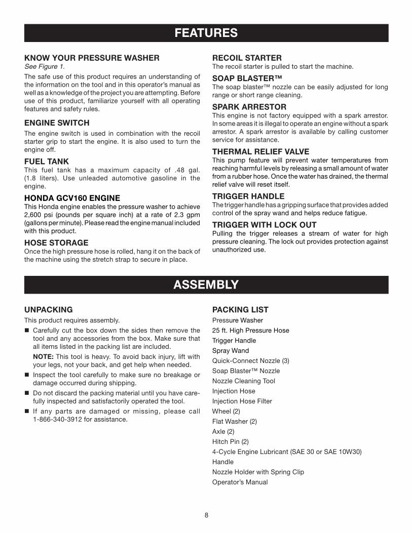
Fig. 13
USING THE SPRAY WAND TRIGGERSee Figure 13.
For greater control and safety, keep both hands on the trigger handle at all times.
Pull back and hold the trigger to operate the pressure washer.
Release the trigger to stop the flow of water through the nozzle.
To engage the lock out: Push up on the lock out until it clicks into the slot.To disengage the lock out: Push the lock out down and into its original position.
For the most effective cleaning, the spray nozzle should be between 8 in. and �4 in. from the surface to be cleaned. If the spray is too close it can damage the cleaning surface.
SELECTING THE RIGHT QUICK-CONNECT NOZZLE FOR THE JOBSee Figure 14 - 15.
Before starting any cleaning job, determine the best nozzle for the job. Each of the nozzles has a different spray pattern. The nozzle patterns are: 25˚ (for general purpose or large surfaces), 15˚ (for tough jobs), 0˚ (for spot cleaning or high-to-reach areas), and the Soap Blaster™ nozzle (for long and short range detergent application).
WARNING:NEVER change nozzles without locking the lock out on the trigger handle and NEVER point the wand at your face or at others. The quick-connect feature contains small springs that could eject the nozzle with some force. Failure to heed this may cause personal injury.
Using the quick-connect collar, changing nozzles is easy.
Turn off the pressure washer and shut off the water supply. Pull trigger to release water pressure.
To connect a nozzle to the trigger handle: Engage the lock out on the trigger handle by pushing up
on the lock out until it clicks into the slot.
Push the nozzle into the quick-connect collar until it clicks in place and is secured properly.
To disconnect a nozzle from the trigger handle once the cleaning job is complete:Turn off the pressure washer and shut off the water
supply. Pull trigger to release water pressure. Engage the lock out on the trigger handle by pushing up
on the lock out until it clicks into the slot. Remove the nozzle by placing hand over nozzle then
pulling back the quick-connect collar. Place nozzle in the nozzle storage area on the top of the machine.
Fig. 14
sLoT
NozzLE
QuICK-CoNNECT CoLLAR
sPRAY wAND
TRIGGER
Fig. 15
“CLICK”
LoCK ouT
LoNG RANGE DETERGENT
APPLICATIoN
sHoRT RANGE DETERGENT
APPLICATIoN
soAP bLAsTER™

15
OPERATION
WASHING WITH DETERGENTSee Figures 16 - 17.
Use only detergents designed for pressure washers; house-hold detergents, acids, alkalines, bleaches, solvents, flam-mable material, or industrial grade solutions can damage the pump. Many detergents may require mixing prior to use. Prepare cleaning solution as instructed on the solution bottle.
Remove the cap from the detergent container and pour detergent in the container. Replace cap on container.
Install the Soap Blaster™ nozzle on the spray wand.
Spray the detergent on a dry surface using long, even, overlapping strokes. To prevent streaking, do not allow detergent to dry on the surface.
NOTE: To use a detergent bottle, open the detergent container cap. Next, remove the filter from the end of the injection hose then slide the hose out of the cap. Place the injection hose filter back on the hose and place the hose in the bottom of the bottle.
For long range detergent application:With the Soap Blaster™ nozzle installed on the spray wand and the engine shut off, pull the nozzle up until it clicks into place.
For short range detergent application:With the Soap Blaster™ nozzle installed on the spray wand and the engine turned off, push the Soap Blaster™ nozzle down as far as it will go.
DETERGENT CoNTAINER
INjECTIoN HosE
Fig. 16
Before shutting off the engine: Place the injection hose in a bucket of clean water.
Flush for 1 - � minutes (spray clear water through the spray wand).
Shut off the engine.
NOTE: Shutting OFF ( O ) the engine will not relieve pressure in the system. Pull trigger to release water pressure.
Fig. 17
LoNG RANGE
sHoRT RANGE

16
OPERATION
RINSING WITH THE PRESSURE WASHERTurn off the pressure washer and shut off the water
supply. Pull trigger to release water pressure.
Engage the lock out on the trigger handle by pushing up on the lock out until it clicks into the slot.
Remove the nozzle by placing hand over nozzle then pulling back the quick-connect collar. Place nozzle in the nozzle storage area on the top of the machine.
Select the right nozzle for the job:
• Use medium pressure nozzle (green) for items such as a car or boat.
• Use higher pressure nozzle for jobs such as stripping paint and degreasing the driveway. When using these nozzles, test a small area first to avoid surface damage.
Start at the top of the area to be rinsed and work down, overlapping the strokes.
MOVING THE PRESSURE WASHERSee Figure 18.
NOTE: Never lift or carry this product using the moving handle. Turn the pressure washer off.
Tilt the machine toward you until it balances on the wheels then roll the machine to the desired position. Fig. 18
To movE THE mACHINE
17
MAINTENANCE
WARNING:
When servicing, use only identical replacement parts. Use of any other parts may create a hazard or cause product damage.
WARNING:
Always wear safety goggles or safety glasses with side shields during power tool operation or when blowing dust. If operation is dusty, also wear a dust mask.
WARNING:
Before inspecting, cleaning or servicing the machine, shut off engine, wait for all moving parts to stop, and discon-nect spark plug wire and move it away from spark plug. Failure to follow these instructions can result in serious personal injury or property damage.
GENERAL MAINTENANCEAvoid using solvents when cleaning plastic parts. Most plastics are susceptible to damage from various types of commercial solvents and may be damaged by their use. Use clean cloths to remove dirt, dust, oil, grease, etc.
WARNING:
Do not at any time let brake fluids, gasoline, petroleum-based products, penetrating oils, etc., come in contact with plastic parts. Chemicals can damage, weaken or destroy plastic which may result in serious personal injury.
Only the parts shown on the parts list are intended to be repaired or replaced by the customer. All other parts should be replaced at an authorized service center.
Before running the engine, perform the following pre- operation steps:
Check that all bolts, nuts, etc., are securely tightened.Make sure the air filter is clean.Check both the engine lubricant level and the fuel tank
level; refill as needed.Inspect the work area for hazards.If there is excessive noise or vibration, stop the unit
immediately.
NOZZLE MAINTENANCESee Figure 19.
Excessive pump pressure (a pulsing sensation felt while squeezing the trigger) may be the result of a clogged or dirty nozzle.
Turn off the pressure washer and shut off the water supply. Pull trigger to release water pressure.
Remove the nozzle from the spray wand.
NOTE: Never point the spray wand at your face.
Using the nozzle cleaning tool provided, free any foreign materials clogging or restricting the nozzle.
Using a garden hose, flush debris out of nozzle by back flushing (running the water through the nozzle backwards or from the outside to the inside).
Reconnect the nozzle to the spray wand.
Turn on the water supply and start the engine.
Fig. 19
NozzLE CLEANING TooL NozzLE

18
MAINTENANCE
STORING THE PRESSURE WASHERSee Figure 20.
Store the pressure washer with the gas tank empty by either draining the tank or running the pressure washer until the gas runs out. Allow 30 minutes of “cool down” time before storing the machine. Store in a dry, covered area where the weather can’t damage it.
It is important to store this product in a frost-free area. Always empty water from all hoses, the pump, and the detergent bucket before storing.
NOTE: Use of a fuel stabilizer and pump saver will give you better performance and increase the life of the machine.
Discharge Fuel:
Drain the fuel tank completely. Stored gas can go stale in 30 days.
Engine Lubricant:
Drain the lubricant and replace with fresh, clean lubricant.
Spark Plug:
Disconnect spark plug wire and remove the spark plug. Pour about a teaspoon of clean, air-cooled, four-cycle lubricant through the spark plug hole into the combustion chamber.
Leaving the spark plug out, pull the starter cord two or three times to coat the inside of the cylinder wall.
Inspect the spark plug and clean or replace, as neces-sary.
Reinstall the spark plug, but leave the spark plug wire disconnected.
Air Filter:
Clean the air filter.
Hoses and Pump:
Flush the injection hose with clean water for 1-� minutes. Remove all hoses. Empty the pump by pulling on the recoil starter about 6 times. This should remove most of the liquid from the pump.
PREPARING FOR USE AFTER STORAGEPull the recoil starter grip three or four times to clean
lubricant from the combustion chamber.
Remove spark plug from the cylinder. Wipe lubricant from the spark plug and return it to the cylinder.
Reconnect the spark plug wire.
Refuel the machine as described earlier in the operator’s manual.
To sToRE THE mACHINE
Fig. �0

19
TROUBLESHOOTING
PROBLEM CAUSE SOLUTION
Engine fails to start 1. No fuel in tank 1. Fill tank
�. Spark plug shorted or fouled �. Replace spark plug
3. Spark plug is broken (cracked 3. Replace spark plug porcelain or electrodes broken)
4. Ignition lead wire shorted, broken, 4. Replace lead wire or attach to spark or disconnected from spark plug plug
5. Ignition inoperative 5. Contact authorized service center
Engine hard to start 1. Water in gasoline 1. Drain entire system and refill with fresh fuel
�. Weak spark at spark plug �. Contact authorized service center
Engine lacks power 1. Dirty air filter 1. Clean or replace air filter
Detergent fails to mix with spray 1. Detergent injection hose is not 1. Insert injection hose into detergent properly submerged container or detergent bottle
�. High pressure nozzle attached �. Use low pressure nozzle (black) to apply detergent
Pump doesn’t produce pressure 1. Low pressure nozzle installed 1. Replace with high pressure nozzle
�. Inadequate water supply �. Provide adequate water flow
3. Trigger handle or spray wand leaks 3. Check connections and / or replace trigger handle or spray wand
4. Nozzle is clogged 4. Clean nozzle
5. Pump is faulty 5. Contact authorized service center
6. Air in line 6. Squeeze trigger on trigger handle to remove air from line
Machine doesn’t reach high 1. Diameter of garden hose is too 1. Replace with 3/4 in. garden hose pressure small
�. Water supply is restricted �. Check garden hose for kinks, leaks, and blockages
3. Not enough inlet water 3. Open water source full force
4. Wrong nozzle is attached 4. Attach the high pressure nozzle

�0
NOTESNOTES
�1
WARRANTY
LIMITED NON-ENGINE WARRANTY STATEMENTTechtronic Industries North America, Inc. warrants to the original retail purchaser that this HUSKY® brand pressure washer is free from defect in material and workmanship and agrees to repair or replace, at Techtronic Industries North America, Inc.’s discretion, any defective product free of charge within this time period from the date of purchase:
Two years if the product is used for personal, family or household use.
This warranty extends to the original retail purchaser only and commences on the date of the original retail pur-chase.
Any part of this product found in the reasonable judgment of Techtronic Industries North America, Inc. to be defective in material or workmanship will be repaired or replaced, without charge for parts and labor, by an Authorized Service Center for HUSKY® brand pressure washers (Authorized HUSKY® Service Center).
The product, including any defective part, must be returned to an Authorized HUSKY® Service Center within the warranty period. The expense of delivering the product to the service center for warranty work and the expense of returning it back to the owner after repair or replacement will be paid for by the owner. Techtronic Industries North America, Inc.’s responsibility in respect to claims is limited to making the required repairs or replacements and no claim of breach of warranty shall be cause for cancellation or rescission of the contract of sale of any HUSKY® brand pressure washer. Proof of purchase will be required by the dealer to substantiate any warranty claim. All warranty work must be performed by an authorized Techtronic Industries North America, Inc. service center.
This warranty does not cover any product that has been subject to misuse, neglect, negligence, or accident, or that is used for rental or commercial purposes, or that has been operated in any way contrary to the operating instructions as specified in the Techtronic Industries North America, Inc. operator’s manual. This warranty does not apply to any damage to the product that is the result of improper maintenance or to any product that has been altered or modified so as to adversely affect the products operation, performance or durability or that has been altered or modified so as to change its intended use. The warranty does not extend to repairs made necessary by normal wear or by the use of parts or accessories which are either incompatible with the HUSKY® brand pressure washer or adversely affect its operation, performance or durability.
In addition, this warranty does not cover:
A. Tune-ups – Air filters, gas filters, spark plugs
B. Wear items – Hoses, connector fittings, spray nozzles, wheels, spray wand, detergent bucket, detergent tank
Techtronic Industries North America, Inc. reserves the right to change or improve the design of any HUSKY® brand pressure washer without assuming any obligation to modify any product previously manufactured.
ALL IMPLIED WARRANTIES ARE LIMITED IN DURATION TO THE STATED WARRANTY PERIOD. ACCORDINGLY, ANY SUCH IMPLIED WARRANTIES INCLUDING MERCHANTABILITY, FITNESS FOR A PARTICULAR PURPOSE, OR OTHERWISE, ARE DISCLAIMED IN THEIR ENTIRETY AFTER THE EXPIRATION OF THE APPROPRIATE ONE-YEAR, WARRANTY PERIOD. TECHTRONIC INDUSTRIES NORTH AMERICA, INC.’S OBLIGATION UNDER THIS WARRANTY IS STRICTLY AND EXCLUSIVELY LIMITED TO THE REPAIR OR REPLACEMENT OF DEFECTIVE PARTS AND TECHTRONIC INDUSTRIES NORTH AMERICA, INC. DOES NOT ASSUME OR AUTHORIZE ANYONE TO AS-SUME FOR THEM ANY OTHER OBLIGATION. SOME STATES DO NOT ALLOW LIMITATIONS ON HOW LONG AN IMPLIED WARRANTY LASTS, SO THE ABOVE LIMITATION MAY NOT APPLY TO YOU. TECHTRONIC INDUSTRIES NORTH AMERICA, INC. ASSUMES NO RESPONSIBILITY FOR INCIDENTAL, CONSEQUENTIAL OR OTHER DAM-AGES INCLUDING, BUT NOT LIMITED TO EXPENSE OF RETURNING THE PRODUCT TO AN AUTHORIZED HUSKY® SERVICE CENTER AND EXPENSE OF DELIVERING IT BACK TO THE OWNER, MECHANIC’S TRAVEL TIME, TELE-PHONE OR TELEGRAM CHARGES, RENTAL OF A LIKE PRODUCT DURING THE TIME WARRANTY SERVICE IS BEING PERFORMED, TRAVEL, LOSS OR DAMAGE TO PERSONAL PROPERTY, LOSS OF REVENUE, LOSS OF USE OF THE PRODUCT, LOSS OF TIME, OR INCONVENIENCE, SOME STATES DO NOT ALLOW THE EXCLUSION OR LIMITATION OF INCIDENTAL OR CONSEQUENTIAL DAMAGES, SO THE ABOVE LIMITATION OR EXCLUSION MAY NOT APPLY TO YOU.
This warranty gives you specific legal rights, and you may also have other rights which vary from state to state.
This warranty applies to all HUSKY® brand pressure washer manufactured by Techtronic Industries North America, Inc. and sold in the United States and Canada.
To locate your nearest Authorized HUSKY® Service Center, dial 1-866-340-391�.
TEchTRONic iNDUSTRiES NORTh AMERicA, iNc.Hwy �
Pickens, SC 29671Phone 1-�66-340-3912
• SERVICENow that you have purchased your tool, should a need ever exist for repair parts or service, simply contact your nearest Authorized Service Center. Be sure to provide all pertinent facts when you call or visit. Please call 1-�66-340-3912 for your nearest Authorized Service Center.
• MODEL NO. AND SERIAL NO.The model number of this tool will be found on a plate attached to the engine. Please record the model number and serial number in the space provided below.
• HOW TO ORDER REPAIR PARTSWhen ordering repair parts, always give the following information:
• MODEL NUMBER
• SERIAL NUMBER
OpERATOR’S MANUAlgASOliNE pRESSURE WAShERhU80722
WARNiNg:The engine exhaust from this product contains chemicals known to the State of California to cause cancer, birth defects, or other reproductive harm.
cAliFORNiA pROpOSiTiON 65
HU�0722
9�7000-2521-3-0� (REV:02)