Embed Size (px)
Citation preview

Wood-Mizer® SawmillSafety, Setup, Operation & Maintenance Manual
LT70HD Remote rev. B3.02 - B7.00
Safety is our #1 concern! Read and understandall safety information and instructions before oper-ating, setting up or maintaining this machine.
January 2010
Form #1671

©2019
Printed in the United States of America, all rights reserved. No part of this manual may be reproduced in any form by any photographic, electronic, mechanical or other means or used in any information storage and retrieval system without written permission from
Wood-Mizer
8180 West 10th Street
Indianapolis, Indiana 46214

Table of Contents Section-Page
TOC
SECTION 1 INTRODUCTION 1-1
1.1 About This Manual.................................................................................1-11.2 Getting Service .......................................................................................1-2
General Contact Information................................................1-2Wood-Mizer Locations..........................................................1-3
1.3 Specifications ........................................................................................1-41.4 Customer and Sawmill Identification.....................................................1-51.5 Warranty .................................................................................................1-7
SECTION 2 SAFETY 2-1
2.1 Safety Symbols.......................................................................................2-12.2 Safety Instructions ..................................................................................2-22.3 Electrical Lockout Procedures..............................................................2-12
SECTION 3 SAWMILL SETUP 3-1
3.1 Stationary Sawmill Setup .......................................................................3-13.2 Portable Sawmill Setup ........................................................................3-103.3 Replacing The Blade ............................................................................3-193.4 Tensioning The Blade...........................................................................3-213.5 Tracking The Blade ..............................................................................3-263.6 Starting The Engine (or Motor)............................................................3-283.7 Board Return ........................................................................................3-29
SECTION 4 SAWMILL OPERATION 4-1
4.1 Hydraulic Control Operation..................................................................4-14.2 Loading, Turning And Clamping Logs ..................................................4-44.3 Up/Down Operation ...............................................................................4-64.4 Blade Guide Arm Operation...................................................................4-74.5 Autoclutch Operation .............................................................................4-84.6 Power Feed Operation ............................................................................4-94.7 Cutting The Log ...................................................................................4-114.8 Edging...................................................................................................4-124.9 Optional Cutting Procedure..................................................................4-134.10 Blade Height Scale ...............................................................................4-144.11 Water Lube Operation ..........................................................................4-164.12 Preparing The Sawmill For Towing .....................................................4-18
SECTION 5 MAINTENANCE 5-1
5.1 Wear Life................................................................................................5-15.2 Blade Guides ..........................................................................................5-25.3 Sawdust Removal ...................................................................................5-45.4 Carriage Track, Wiper & Scraper...........................................................5-55.5 Vertical Mast Rails .................................................................................5-7
Table of Contents WMdoc072619 iii

Table of Contents Section-Page
5.6 Drum Switches .......................................................................................5-85.7 Miscellaneous .........................................................................................5-95.8 Blade Tensioner....................................................................................5-105.9 Blade Wheel Belts ................................................................................5-135.10 Drive Belt Adjustment..........................................................................5-14
Adjust belt tension...............................................................5-15Adjust the drive belt support (Excludes E25, E30, D55) ....5-16
5.11 Brake Adjustment (DC Only)...............................................................5-175.12 Autoclutch Belt (DC Only) ..................................................................5-185.13 Hydraulic System .................................................................................5-195.14 Up/Down System..................................................................................5-215.15 Power Feed ...........................................................................................5-265.16 Charging The Battery (DC Only) .........................................................5-285.17 Remote Cable Chain & Support Tray ..................................................5-305.18 Maintenance chart ................................................................................5-33
5.18 MAINTENANCE LOG 5-33
SECTION 6 TROUBLESHOOTING GUIDE 6-1
6.1 Sawing Problems ....................................................................................6-16.2 Electrical Problems.................................................................................6-36.3 Circuit Breaker Operation ......................................................................6-56.4 Power Feed Problems .............................................................................6-86.5 Power Feed Variable Feed Rate Switch Test .......................................6-106.6 Power Feed Mechanical Test................................................................6-116.7 Hydraulic Problems ..............................................................................6-126.8 Hydraulic Pressure Test........................................................................6-166.9 Engine/Motor and Drive Pulleys Alignment........................................6-17
iv WMdoc072619 Table of Contents
Table of Contents Section-Page
TOC
SECTION 7 SAWMILL ALIGNMENT 7-1
7.1 Routine Alignment Procedure ................................................................7-1Blade Installation..................................................................7-1Saw Head Tilt .....................................................................7-1Blade Guide Arm Alignment .................................................7-3Blade Guide Vertical Tilt Alignment.....................................7-7Blade Guide Horizontal Tilt Adjustment...............................7-8Blade Guide Flange Spacing ..............................................7-10Manual Side Support Alignment .........................................7-11Hydraulic Side Support Alignment .....................................7-13Blade Height Scale Adjustment (All Mills Except LT70 Super HD)7-14
7.2 Complete Alignment Procedure ...........................................................7-16Frame Setup ...................................................................7-16Blade Installation................................................................7-16Blade Wheel Alignment.......................................................7-17Track Roller Adjustment .....................................................7-21Bed Rail Adjustment............................................................7-24Blade Guide Installation .....................................................7-26Blade Guide Arm Alignment ...............................................7-28Blade Guide Deflection.......................................................7-33Blade Guide Vertical Tilt Alignment...................................7-33Blade Guide Horizontal Tilt Adjustment.............................7-35Blade Guide Flange Spacing ..............................................7-36Blade Guide Level ...............................................................7-37Blade Block Adjustment ......................................................7-38Manual Side Support Alignment .........................................7-40Hydraulic Side Support Alignment .....................................7-41Clamp Stop/Stop Bolt Adjustment .......................................7-42Saw Head Tilt ...................................................................7-43Blade Height Scale Adjustment (All Mills Except LT70 Super HD)7-45
SECTION 8 HYDRAULIC INFORMATION 8-1
8.1 Hydraulic Schematic .........................................................................8-18.2 Hydraulic Layout Diagram ....................................................................8-28.3 Hydraulic Components...........................................................................8-38.4 Hydraulic Hoses .....................................................................................8-4
INDEX I
Table of Contents WMdoc072619 v
IntroductionAbout This Manual1
1-1 60HD-R10doc072619 Introduction
SECTION 1 INTRODUCTION
1.1 About This Manual
This manual is to replace or to be used with all previous information received on the
Wood-Mizer®* sawmill. All future mailings will be an addition to or a revision of individualsections of this manual as we obtain new information.
The information and instructions given in this manual do not amend or extend the limitedwarranties for the equipment given at the time of purchase.
For general information regarding Wood-Mizer and our “Forest to Final Form” products,please refer to the All Products Catalog in your support package.
*.Wood-Mizer® is a registered trademark of Wood-Mizer LLC.U.S. Patent No. 6,655,429.
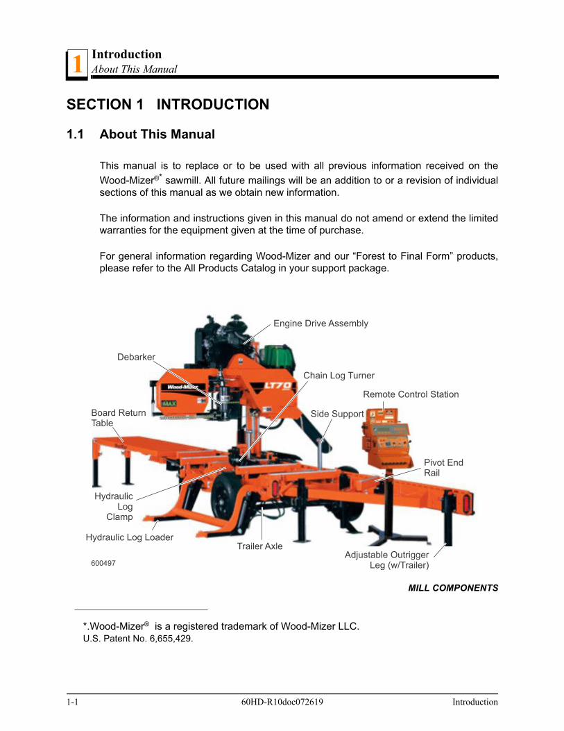
MILL COMPONENTS
600497
Engine Drive Assembly
Remote Control Station
Hydraulic Log Loader
Side Support
Chain Log Turner
Trailer Axle
Debarker
Board ReturnTable
Adjustable OutriggerLeg (w/Trailer)
Pivot EndRail
Hydraulic Log
Clamp

IntroductionGetting Service 1
1.2 Getting Service
Wood-Mizer is committed to providing you with the latest technology, best quality andstrongest customer service available on the market today. We continually evaluate ourcustomers’ needs to ensure we’re meeting current wood-processing demands. Yourcomments and suggestions are welcome.
General Contact Information
Toll free phone numbers are listed below for the continental U.S. and Canada. See thenext page for contact information for more Wood-Mizer locations.
Office Hours: All times are Eastern Standard Time.
Please have your vehicle identification number and your customer number ready whenyou call.
Wood-Mizer will accept these methods of payment:
Visa, Mastercard, or Discover
COD
Prepayment
Net 15 (with approved credit)
Be aware that shipping and handling charges may apply. Handling charges are based onsize and quantity of order. In most cases, items will ship on the day they are ordered.Second Day and Next Day shipping are available at additional cost.
If your sawmill was purchased outside the United States or Canada, contact the distribu-tor for service.
United States Canada
Sales 1-800-553-0182 1-877-866-0667
Service 1-800-525-8100 1-877-866-0667
Website www.woodmizer.com www.woodmizer.ca
E-mail [email protected] [email protected]
Monday - Friday Indianapolis Office ONLYSaturday
Sunday
8 a.m. to 5 p.m. 8 a.m. to 12 p.m. Closed
Introduction 60HD-R10doc072619 1-2
IntroductionWood-Mizer Locations1
Wood-Mizer Locations
USA World Headquarters Canadian Headquarters
Serving North & South America, Oceania, East Asia
Wood-Mizer LLC8180 West 10th StreetIndianapolis, IN 46214
Phone: 317.271.1542 or 800.553.0182Customer Service: 800.525.8100Fax: 317.273.1011Email: [email protected]
Serving Canada
Wood-Mizer Canada396 County Road 36, Unit BLindsay, ON K9V 4R3
Phone: 705.878.5255 or 877.357.3373Fax: 705.878.5355Email: [email protected]
Brazilian Headquarters European Headquarters
Serving Brazil
Wood-Mizer do BrasilRua Dom Pedro 1, No: 205 Bairro: Sao JoseIvoti/RS CEP:93.900-000
Tel: +55 51 9894-6461/ +55 21 8030-3338/ +55 51 3563-4784Email: [email protected]
Serving Europe, Africa, West Asia
Wood-Mizer Industries Sp z o.o.Nagorna 11462-600 Kolo, Poland
Phone: +48.63.26.26.000Fax: +48.63.27.22.327
Branches & Authorized Sales Centers
For a complete list of dealers, visit www.woodmizer.com
1-3 60HD-R10doc072619 Introduction
IntroductionSpecifications
Introduction 60HD-R10doc072619 1-4
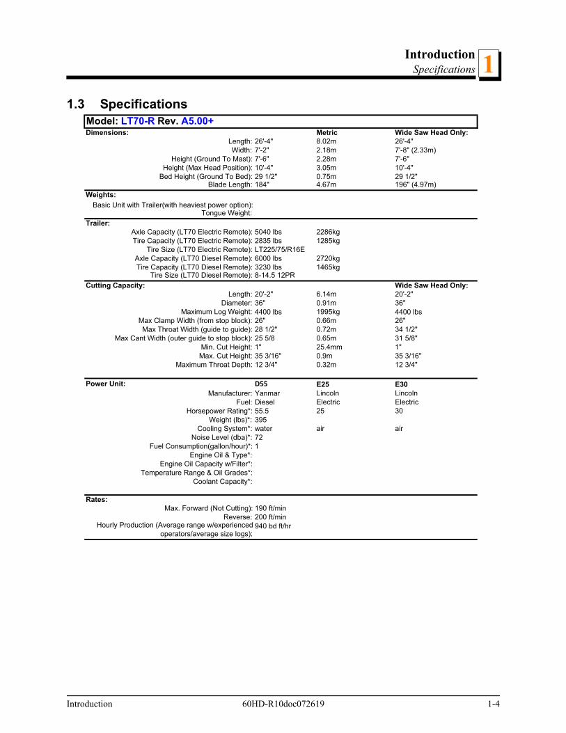
11.3 Specifications
Model: LT70-R Rev. A5.00+Dimensions: Metric Wide Saw Head Only:
Length: 26'-4" 8.02m 26'-4"Width: 7'-2" 2.18m 7'-8" (2.33m)
Height (Ground To Mast): 7'-6" 2.28m 7'-6"Height (Max Head Position): 10'-4" 3.05m 10'-4"
Bed Height (Ground To Bed): 29 1/2" 0.75m 29 1/2"Blade Length: 184" 4.67m 196" (4.97m)
Weights:Basic Unit with Trailer(with heaviest power option):
Tongue Weight:Trailer:
Axle Capacity (LT70 Electric Remote): 5040 lbs 2286kgTire Capacity (LT70 Electric Remote): 2835 lbs 1285kg
Tire Size (LT70 Electric Remote): LT225/75/R16EAxle Capacity (LT70 Diesel Remote): 6000 lbs 2720kgTire Capacity (LT70 Diesel Remote): 3230 lbs 1465kg
Tire Size (LT70 Diesel Remote): 8-14.5 12PRCutting Capacity: Wide Saw Head Only:
Length: 20'-2" 6.14m 20'-2"Diameter: 36" 0.91m 36"
Maximum Log Weight: 4400 lbs 1995kg 4400 lbsMax Clamp Width (from stop block): 26" 0.66m 26"Max Throat Width (guide to guide): 28 1/2" 0.72m 34 1/2"
Max Cant Width (outer guide to stop block): 25 5/8 0.65m 31 5/8"Min. Cut Height: 1" 25.4mm 1"Max. Cut Height: 35 3/16" 0.9m 35 3/16"
Maximum Throat Depth: 12 3/4" 0.32m 12 3/4"
Power Unit: D55 E25 E30Manufacturer: Yanmar Lincoln Lincoln
Fuel: Diesel Electric ElectricHorsepower Rating*: 55.5 25 30
Weight (lbs)*: 395Cooling System*: water air air
Noise Level (dba)*: 72Fuel Consumption(gallon/hour)*: 1
Engine Oil & Type*:Engine Oil Capacity w/Filter*:
Temperature Range & Oil Grades*:Coolant Capacity*:
Rates:Max. Forward (Not Cutting): 190 ft/min
Reverse: 200 ft/minHourly Production (Average range w/experienced
operators/average size logs):940 bd ft/hr
IntroductionCustomer and Sawmill Identification1
1.4 Customer and Sawmill Identification
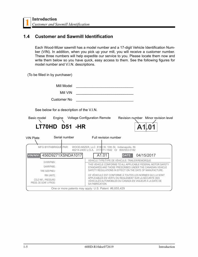
Each Wood-Mizer sawmill has a model number and a 17-digit Vehicle Identification Num-ber (VIN). In addition, when you pick up your mill, you will receive a customer number.These three numbers will help expedite our service to you. Please locate them now andwrite them below so you have quick, easy access to them. See the following figures formodel number and V.I.N. descriptions.
See below for a description of the V.I.N.
(To be filled in by purchaser)
Mill Model _____________________________
Mill VIN _____________________________
Customer No _____________________________
WOOD-MIZER, LLC 8180 W. 10th St. Indianapolis, IN 46214-2400 U.S.A. 317/271-1542 Or 800/553-0182
MFG BY/FABRIQUÉ PAR:
VIN/NIV: DATE:
One or more patents may apply: U.S. Patent #6,655,429
456D9271XSNDA1017 A1.01 04/15/2017
A1.01Serial number
Basic model Engine Revision number Minor revision level
Full revision numberVIN Plate
LT70HD D51 -HR
Voltage Configuration Remote
1-5 60HD-R10doc072619 Introduction

IntroductionCustomer and Sawmill Identification 1
Com
pany
Ide
ntifi
catio
n N
umbe
r
Wei
ght
Cla
ss
Pro
duct
De
sig
natio
n n
umbe
r
Leng
th o
f th
e T
raile
r
Axl
e c
oun
t
Che
ck D
igit
Ye
ar o
f M
anuf
actu
re
(cod
ed)
Ma
nufa
ctu
re lo
catio
n
Mo
nth
of
Ma
nuf
actu
re
Rev
isio
n Le
vel
Se
que
nce
Num
ber
SampleVIN
456 D 9 27 1 X S N D A1 017
V.I.N. DESCRIPTION
Introduction 60HD-R10doc072619 1-6

IntroductionWarranty1
1.5 Warranty
Wood-Mizer® LLCLimited Product Warranty
Wood-Mizer LLC (“Warrantor”), an Indiana corporation with its principal place of business at 8180 West TenthStreet, Indianapolis, IN 46214-2400 USA, warrants to the purchaser (“Purchaser”) that for the time periodsspecifically stated herein and subject to the terms, conditions and limitations stated herein, the equipmentmanufactured by the Warrantor will be free from defects in material and workmanship attributable to Warran-tor so long as, during the warranty periods stated herein, the equipment is installed, operated and maintained
in accordance with the instructions provided by Warrantor.
EXCLUSIONS FROM 90 DAY, LIMITED ONE YEAR AND TWO YEAR WARRANTY Warrantor shall have no responsibility under this warranty for any wear components, including, but not limitedto: belts, blade guides, blades, electric motor brushes, drum switches, filters, fuses, hoses, bearings (exclud-ing cylindrical drive bearings), bushings, cable carriers, and spark plugs. All wear components are furnished“as is”, without any warranty from Warrantor. This limited warranty does not cover any defects caused by
PRODUCT MODEL CLASSLENGTH OF WARRANTY
EFFECTIVE DATEUSA & CANADA
NON USA & CANADA
Portable Sawmills, Resaws, Edgers
LT, LX, HR, EG Two years One year
Date of purchase Portable Sawmills with Chassis
LT28, LT35, LT40, LT50, LT70, LX450
Two years, excluding the chassis, which chassis shall have a five year warranty
One year
Industrial Sawmills, Resaws, Edgers
WM, HR, EG, TVS, SVS, FS
One year One year Date of purchase or date of installation / training (if applicable), whichever occurs first, not to exceed 6 months from date of purchase
TITAN Industrial WB, TV, HR, EG, EA, MR One year One year
Material HandlingTWC, IC, TD, LD, GC, CR, CB, CC
One year One year
Blade Maintenance Equipment BMS, BMT, BMST One year One year
Date of purchase
Options and Accessories Various One year1 One year1
1 Warranty on Options will match the warranty on the primary equipment when purchased on same invoice.
Moulders, Kilns MP, SD, KD One year One year
Pallet Dismantler PD One year One year
Log Splitter FS One year One year
Replacement Parts Various 90 days 90 days
1-7 60HD-R10doc072619 Introduction

IntroductionWarranty 1
misuse, negligence, alterations, damage due to overload, abnormal conditions, excessive operation, acci-dent, or lack of performance of normal maintenance services.
Several components which are used in the manufacture of the equipment but not manufactured by Warrantor,such as cant hooks, power plants, laser sights, batteries, tires, and trailer axles have warranties provided bythe original equipment manufacturer (written copies available upon request). Warrantor does not separatelywarrant such items. Components or equipment manufactured by third parties are not covered by this war-ranty. Warrantor, however, will provide reasonable assistance to the Purchaser to make claims against anywarranties applicable to such component parts as provided by such original equipment manufacturers. Com-ponents or equipment manufactured by third parties are not covered by this Warranty.
FIVE YEAR LIMITED CHASSIS WARRANTY The limited five year chassis warranty, described above, DOES NOT extend to (a) any damage stemmingfrom accident, improper towing, overload, abuse, misuse, abnormal conditions, negligence, excessive opera-tion, or lack of maintenance, (b) rust caused by exposure to corrosive atmospheric conditions, or (c) the saw-mill head, carriage, axle, brakes, or any hydraulic or electrical components attached to the chassis.
WARRANTOR’S OBLIGATIONS AS TO DEFECTSIn the event that the equipment fails to perform due to defective materials or workmanship attributable to War-rantor under normal use and service within the established warranty period, Purchaser’s sole and exclusiveremedy and Warrantor’s sole liability shall be to replace or repair, in Warrantor’s sole and subjective discre-tion, any defective part at Warrantor’s principal place of business without cost to the Purchaser if such defectexists. The determination of whether a product is defective shall be made by Warrantor in Warrantor’s soleand subjective discretion. The Purchaser must notify Warrantor prior to shipping any defective part. Warran-tor, at its sole discretion, may cover expenses incurred in shipping the defective part to Warrantor for evalua-tion; provided, however, that Warrantor will not be responsible for labor, travel time, mileage, removal,installation, and/or incidental or consequential damages. However, any part in excess of 140 pounds must bereturned by the Purchaser to the Warrantor’s nearest authorized facility at the Purchaser’s expense, if returnis requested by Warrantor. Warrantor shall have a reasonable time within which to repair or replace the defec-tive part. If Warrantor determines that the product is not defective under the terms of this warranty in Warran-tor’s sole and subjective discretion, then Purchaser shall be responsible for any expenses incurred byWarrantor in returning the equipment to the Purchaser.
LIMITATIONS AND DISCLAIMERS OF OTHER WARRANTIESEXCEPT FOR THE EXPRESS WARRANTY PROVISIONS STATED ABOVE, WARRANTOR DISCLAIMSALL WARRANTIES, EXPRESS AND/OR IMPLIED, INCLUDING AND WITHOUT LIMITATION, THEIMPLIED WARRANTIES OF MERCHANTABILITY, AND FITNESS FOR A PARTICULAR PURPOSE, NONIN-FRINGEMENT AND TITLE. No representation or other affirmation of fact by representatives of Warrantor,whether verbal or in writing, including photographs, brochures, samples, models, or other sales aids, shallconstitute a warranty, or any other basis, for any legal action against Warrantor. There are no other represen-tations, promises, agreements, covenants, warranties, guarantees, stipulations or conditions, expressed orimplied, by Warrantor, except as expressly set forth herein. THE PURCHASER AND ANY INTENDED USEROR BENEFICIARY OF THIS EQUIPMENT, SHALL NOT BE ENTITLED TO RECOVER ANY INDIRECT,SPECIAL, PUNITIVE, EXEMPLARY, CONSEQUENTIAL, SPECIAL, OR INCIDENTIAL DAMAGES ORLOSES, INCLUDING BUT NOT LIMITED TO, DAMAGES OF LOST PRODUCTION, LOST REVENUE,LOST PRODUCT, LOST PROFITS, LOST BUSINESS, LOSS OF USE, LOSS OF GOODWILL, OR BUSI-NESS INTERRUPTION, FROM WARRANTOR FOR ANY REASON WHATSOEVER INCLUDING, WITHOUTLIMITATION, WARRANTY OR DEFECT IN THE PRODUCT REGARDLESS OF THE SOLE, JOINT, AND/ORCONCURRENT NEGLIGENCE, BREACH OF CONTRACT, BREACH OF WARRANTY, STRICT LIABILITYIN TORT OR STATUTORY CLAIMS, OR OTHER LEGAL FAULT, OR RESPONSIBILITY OF EITHER WAR-RANTOR OR PURCHASER OR ITS EMPLOYEES OR AGENTS. Warrantor does not warrant that its equip-ment meets or complies with the requirements of any particular safety code or governmental requirements.
Defective items, replaced under the terms of this warranty, become the property of Warrantor.
Introduction 60HD-R10doc072619 1-8

IntroductionWarranty1
DESIGN CHANGESWarrantor reserves the right to change the design of its products from time to time without notice and withoutobligation to make corresponding changes in or to its products previously manufactured.
RIGHTS OF PURCHASERSThe validity and effect of this limited warranty, as well as its interpretation, operation and effect, shall be deter-mined exclusively by the principles of law and equity of the State of Indiana, USA. This limited warranty givesPurchaser specific legal rights. Purchaser may also have other rights, which may vary from state to state.Some states may not allow limitations as to the duration of implied warranties or to the exclusion or limitationof incidental or consequential damages, therefore some of the limitations and exclusions detailed set forthabove may not apply. In the event that any one or more of the provisions of this warranty shall be or becomeinvalid, illegal or unenforceable in any respect, the validity, legality and enforceability of the remaining provi-sions of this warranty shall not be affected thereby.
INTERPRETATIONSThis Warranty constitutes the entire warranty agreement between Warrantor and Purchaser and supersedes anyprior understandings or agreements pertaining to the same subject matter. This warranty cannot be amended,except in writing, which refers to this warranty that is signed by both Warrantor and Purchaser.
© 2018 Wood-Mizer LLC – 8180 West 10th Street, Indianapolis, IN 46214
1-9 60HD-R10doc072619 Introduction

SafetySafety Symbols
Safety 60HD-R10doc072619 2-1
2
SECTION 2 SAFETY
2.1 Safety Symbols
The following symbols and signal words call your attention to instructions concerning yourpersonal safety. Be sure to observe and follow these instructions.
DANGER! indicates an imminently hazardous situation which, if notavoided, will result in death or serious injury.
WARNING! suggests a potentially hazardous situation which, if notavoided, could result in death or serious injury.
CAUTION! refers to potentially hazardous situations which, if notavoided, may result in minor or moderate injury or damage to equip-ment.
IMPORTANT! indicates vital information.
NOTE: gives helpful information.

SafetySafety Instructions2
2.2 Safety Instructions
OWNER’S RESPONSIBILITY
The procedures listed in this manual may not include all ANSI, OSHA, or locally requiredsafety procedures. It is the owner/operator’s responsibility and not Wood-Mizer Productsto ensure all operators are properly trained and informed of all safety protocols.Owner/Operators are responsible for following all safety procedures when operating andperforming maintenance to the sawmill.
NOTE: ONLY safety instructions regarding personal injury are listed inthis section. Caution statements regarding only equipment damageappear where applicable throughout the manual.
WARNING! Clean sawdust from all guards, vents, con-trol boxes, or any area where sawdust may gather afterevery shift. Failure to do so may result in fire, causingdeath or serious injury.
OBSERVE SAFETY INSTRUCTIONS
IMPORTANT! Read the entire Operator's Manual before operating thesawmill. Take notice of all safety warnings throughout this manual andthose posted on the machine. Keep this manual with this machine at alltimes, regardless of ownership.
Also read any additional manufacturer’s manuals and observe anyapplicable safety instructions including dangers, warnings, and cau-tions.
Only persons who have read and understood the entire operator'smanual should operate the sawmill. The sawmill is not intended for useby or around children.
IMPORTANT! It is always the owner'sresponsibility to comply with all applicablefederal, state and local laws, rules and regu-lations regarding the ownership, operationand towing of your Wood-Mizer sawmill. AllWood-Mizer mill owners are encouraged tobecome thoroughly familiar with these appli-cable laws and comply with them fully whileusing or towing the mill.
2-2 60HD-R10doc072619 Safety

SafetySafety Instructions 2
WEAR SAFETY CLOTHING
WARNING! Secure all loose clothing and jewelry before operating thesawmill. Failure to follow this may result in serious injury or death.
WARNING! Always wear gloves and eye pro-tection when handling bandsaw blades. Chang-ing blades is safest when done by one person!Keep all other persons away from area whencoiling, carrying or changing a blade. Failure tofollow this may result in serious injury or death.
WARNING! Always wear eye, ear, and foot protectionwhen operating or servicing the sawmill.
WARNING! Some woods require respiration protectionwhen operating the sawmill. It is the sawyer’s responsibil-ity to know which woods require respiration protection.
KEEP SAWMILL AND AREA AROUND SAWMILL CLEAN
DANGER! Maintain a clean and clear path for all necessary movementaround the mill and lumber stacking areas. Failure to follow this willresult in serious injury or death.
HANDLE FUEL/LUBRICANTS SAFELY
DANGER! Do not smoke, weld, grind or allow sparks near your engineor storage tanks, especially during times of fueling. Failure to followthis will result in serious injury or death.
DANGER! Never allow fuel to spill on a hot engine during fueling oper-ations or otherwise. The hot temperature of your engine could induce afire or explosion. Failure to follow this will result in serious injury ordeath.
WARNING! Store gasoline away from sawdust and otherflammable materials. Failure to follow this may result inserious injury or death.
WARNING! Use ONLY water and Wood-Mizer Lube Addi-tive with the water lube accessory. Never use flammablefuels or liquids such as diesel fuel. If these types of liquidsare necessary to clean the blade, remove it and clean witha rag. Failure to follow this couldresult in serious injury or death.
Safety 60HD-R10doc072619 2-3

SafetySafety Instructions2
WARNING! Drum switch grease contains Petroleum HydrocarbonLubricant. Eye and skin irritant. If introduced into eyes, flush with waterfor at least 15 minutes. If film or irritation persists, seek medical atten-tion. Wash skin with soap and water. If ingested, do not induce vomit-ing - contact a physician. KEEP OUT OF THE REACH OF CHILDREN.
DISPOSE OF SAWING BY-PRODUCTS PROPERLY
IMPORTANT! Always properly dispose of all sawing by-products,including sawdust and other debris, coolant, oil, fuel, oil filters and fuelfilters.
USE CAUTION WHEN WORKING WITH BATTERIES (ENGINES ONLY)
DANGER! Batteries expel explosive gases; keep sparks, flames,burning cigarettes, or other ignition sources away at all times. Fail-ure to follow this will result in serious injury or death.
WARNING! Always wear safety goggles and a face shield whenworking near batteries. Failure to follow this could result in seriousinjury or death.
WARNING! Wash hands after handling batteries to remove possi-ble lead, acid, or other contaminants. Failure to follow this couldresult in serious injury or death.
WARNING! Charge the battery in a well ventilated area. Failure tofollow this could result in serious injury or death.
WARNING! Do not attempt to charge a frozen battery. Failure tofollow this could result in serious injury or death.
IMPORTANT! When working with batteries, use extreme care toavoid spilling or splashing electrolyte (dilute sulfuric acid) as it candestroy clothing and burn the skin.
2-4 60HD-R10doc072619 Safety

SafetySafety Instructions 2
CAUTION! Do not overcharge the battery. Overcharging couldreduce the overall service life of the battery.
CAUTION! Be sure the battery is fully charged before transportingthe sawmill. If the battery is not fully charged, excessive vibrationcould reduce the overall service life of the battery.
CAUTIONS FOR SAWMILL SETUP
WARNING! Do not set up the mill on ground with more than a 10degree incline.Failure to follow this could result in serious injury ordeath.
If setup on an incline is necessary, put blocks under one side of the millor dig out areas for the outrigger legs to keep mill level. Setting up themill on an incline could cause it to tip over.
WARNING! Chock the trailer wheels to prevent movement beforeunhitching it from the towing vehicle. Failure to follow this could resultin serious injury or death.
WARNING! Put front outrigger down before moving saw head from therest position. Failure to follow this could result in serious injury ordeath.
WARNING! Always make sure the trailer is supporting the sawmillframe when operating a sawmill with adjustable outriggers. Failure tofollow this could result in serious injury or death. The adjustable outrig-
EMERGENCY TREATMENT FOR CONTACT WITH BATTERY COMPONENTS (LEAD/SUL-FURIC ACID) per SDS (Safety Data Sheet):
EYE CONTACT Sulfuric Acid and Lead: Flush eyes immediately with large amounts of water for at least 15 minutes while lifting lids. Seek immediate medical atten-tion if eyes have been exposed directly to acid.
SKIN CONTACT Sulfuric Acid: Flush affected area(s) with large amounts of water using del-uge emergency shower, if available, shower for at least 15 minutes. Remove contaminated clothing, including shoes. If symptoms persist, seek medical attention. Wash contaminated clothing before reuse. Discard contaminated shoes.Lead: Wash immediately with soap and water.
INGESTION Sulfuric Acid: Administer large amounts of water. Do NOT induce vomiting or aspiration into the lungs may occur and can cause permanent injury or death; consult physician.
INHALATION Sulfuric Acid: Remove to fresh air immediately. If not breathing, give artificial respiration. If breathing is difficult, give oxygen. Consult a physician.Lead: Remove from exposure, gargle, wash nose and lips; consult physician.
Safety 60HD-R10doc072619 2-5
SafetySafety Instructions2
gers are intended to support the saw frame with assistance from thetrailer.
WARNING! The adjustable outriggers supplied with portable sawmillsare not intended for setup on concrete or other hard surfaces.Long-term use of the adjustable outriggers on hard surfaces couldcause the outriggers to fail. If setting the sawmill up on concrete orother hard surface, replace the adjustable outrigger legs with station-ary legs. Failure to follow this could result in serious injury or death.
WARNING! Securely fasten the feet of a stationary sawmill to the floorbefore operating the sawmill. Failure to follow this could result in seri-ous injury or death.
CHECK SAWMILL/BLADES BEFORE OPERATION
DANGER! Ensure the blade housing and pulley covers are in placeand secure. Failure to follow this could result in serious injury or death.
DANGER! Ensure all guards and covers are in place and securedbefore operating or towing the sawmill. Failure to follow this couldresult in serious injury or death.
DANGER! Do not use blades with stress cracks. Failure to follow thiscould result in serious injury or death.
Blade guide alignment is essential for optimal cutting performance,blade life and safety. Failure to check and maintain proper blade guidealignment will result in stress cracks forming in the blade. Thesecracks will lead to premature blade breakage. If the blade breaksduring operation and the blade has multiple stress cracks, the bladecould shatter into several pieces and escape from the protectiveguards of the sawmill. Small blade pieces projected into the areaaround the sawmill creates a safety hazard for the operator and anybystanders surrounding the mill.
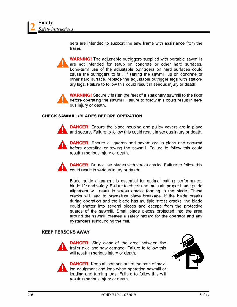
KEEP PERSONS AWAY
DANGER! Stay clear of the area between thetrailer axle and saw carriage. Failure to follow thiswill result in serious injury or death.
DANGER! Keep all persons out of the path of mov-ing equipment and logs when operating sawmill orloading and turning logs. Failure to follow this willresult in serious injury or death.
2-6 60HD-R10doc072619 Safety

SafetySafety Instructions 2
DANGER! Always be sure the blade is disen-gaged and all persons are out of the path of theblade before starting the engine or motor. Failureto follow this will result in serious injury or death.
KEEP HANDS AWAY
DANGER! Always disengage the blade and shut off the sawmill enginebefore changing the blade. Failure to follow this will result in seriousinjury or death.
DANGER! Engine components can become very hot during operation.Avoid contact with any part of a hot engine. The exhaust componentsof your engine are especially hot during and following operation. Con-tact with hot engine components can cause serious burns. Therefore,never touch or perform service functions on a hot engine. Allow theengine to cool sufficiently before beginning any service function.
DANGER! Always keep hands away from moving bandsaw blade.Failure to follow this will result in serious injury or death.
DANGER! Always be aware of and take proper protective measuresagainst rotating shafts, pulleys, fans, etc. Always stay a safe distancefrom rotating members and make sure that loose clothing or long hairdoes not engage rotating members resulting in serious injury or death.
WARNING! Do not spin the blade wheels by hand.Spinning the blade wheels by hand could result inserious injury or death.
WARNING! Always disengage the clutch/brakemechanism whenever the sawmill is not cutting.Failure to follow this could result in serious injury ordeath.
WARNING! Do not for any reason adjust the engine drive belts or beltsupport bracket with the engine running. Doing so could result in seri-ous injury or death.
WARNING! Always keep clear of exiting sawdust. Keep hands, feetand any other objects away from the sawdust chute when operatingsawmill. Failure to follow this could result in serious injury or death.
Safety 60HD-R10doc072619 2-7

SafetySafety Instructions2
CAUTIONS FOR GAS OR DIESEL ENGINE OPERATION
DANGER! Operate your engine/machine only in well ventilated areas.The exhaust gases of your engine can cause nausea, delirium andpotentially death unless adequate ventilation is present.
DANGER! Never operate an engine with a fuel or oil leak. The leakingfuel or oil could potentially come in contact with hot surfaces and igniteinto flames.
WARNING! Do not operate engine without proper and operationalspark arrester/muffler. Sparks emitted from the engine exhaust couldignite surrounding materials, causing serious injury or death.
KEEP SAFETY LABELS IN GOOD CONDITION
IMPORTANT! Inspect all safety decals to ensure they are clean andreadable. Replace all damaged safety decals to prevent personalinjury or damage to the equipment. Contact your local distributor, orcall your Customer Service Representative to order more decals.
IMPORTANT! If replacing a component which has a safety decalaffixed to it, make sure the new component also has the safety decalaffixed.
USE CAUTION WHEN WORKING WITH HEAVY LOGS
WARNING! Always make sure log is clamped securely before sawing.Failure to follow this could result in serious injury or death.
WARNING! Always leave hydraulic loading arm halfway up while log ison sawmill bed. Failure to follow this could result in serious injury ordeath.
AUTOMATIC BOARD RETURN SAFETY
DANGER! Keep all persons out of the path of returning boards. Failureto follow this will result in serious injury or death.
WARNING! The automatic board return is intended to assist a secondoperator in removing boards quickly. Do not use the board return whenoperating the sawmill alone. Serious injury, death or damage to theequipment could result.
2-8 60HD-R10doc072619 Safety

SafetySafety Instructions 2
WARNING! Never use the board return table as a platform to stand on.This table is designed and intended to assist in the removal of boardsonly. Standing on the table could result in serious injury or death.
UP/DOWN SYSTEM SAFETY
WARNING! Always secure the saw head with a 5/16" chain with atleast 1900 lbs. working load capacity before adjusting the up/downchain. The saw head could fall, causing severe injury or death.
WARNING! Always secure the saw head with a 5/16" chain withapproximately 1900 lbs. working load capacity before removing theup/down motor belt. The saw head could fall, causing severe injury ordeath.
WARNING! Always secure the saw head with a 5/16" chain with atleast 1900 lbs. working load capacity before servicing the up/downassist (Rev. A5.00+). The cutting head could fall, causing severe injuryor death.
WARNING! Release pressure from the up/down assist prior to per-forming any service to the assembly (Rev. A5.00+). Failure to followthis could result in the assembly flying apart, causing serious injury ordeath.
WARNING! The gas spring cylinders are pressurized (Rev. A5.00+).Disassembly of cylinder may result in serious injury or death.
POWER FEED SYSTEM SAFETY
DANGER! If leaving the blade engaged for maximum production rates,make sure the off-bearer stays out of the path of the blade. Failure tofollow this will result in serious injury or death.
WARNING! Be sure the power feed switch is in the neutral positionbefore turning the key switch to the on (#1) or accessory (#3) position.This prevents accidental carriage movement which may cause seriousinjury or death.
GENERAL TRAILER SAFETY
DANGER! Make sure your hitch has adequate safety chain hookups.Do not use eyebolts for safety chain hook-up. Safety chains should behooked to bumper of vehicle so that each chain would pull the trailerequally in the event the hitch became disengaged. Failure to follow thiswill result in serious personal injury and/or severe machine damage.
Safety 60HD-R10doc072619 2-9

SafetySafety Instructions2
DANGER! Be sure that the hitch and safety chains are secure beforetowing the sawmill. Failure to follow this will result in serious personalinjury and/or severe machine damage.
DANGER! Make sure all light connections have been made and areworking properly before towing the sawmill. Failure to follow this willresult in serious personal injury and/or severe machine damage.
WARNING! The trailer option is designed for the express purpose oftowing the sawmill it is supplied with. Do not make modifications oradditions that affect the weight and/or stability of the towing unit. Doingso could result in property damage and/or serious injury or death.
WARNING! Always check trailer tires for proper inflation before towingsawmill. Failure to follow this could lead to tire failure resulting in prop-erty damage and/or serious injury or death.
CAUTION! Move the hydraulic clamp and turner to provide maximumground clearance before towing. Failure to follow this could result indamage to the sawmill.
ADDITIONAL SAFETY FOR ELECTRIC BRAKE TRAILERS
DANGER! Make sure the electric brake wire is secured as close to thetrailer axle as possible to prevent wire disconnection during towing.Failure to follow this will result in serious personal injury or death.
DANGER! Be sure electric brake battery is charged and is workingproperly before towing the sawmill. Failure to follow this will result inserious personal injury or death.
DANGER! Do not use the electric brake system as an “emergencybrake” while the sawmill is not being towed. Extended use of the elec-tric brakes while the sawmill is stationary will drain the brake battery.
DEBARKER ACCESSORY SAFETY
DANGER! Make sure all guards and covers are in place and securedbefore operating the debarker option. Failure to follow this will result inserious injury or death.
DANGER! Keep all persons out of the path of moving equipment whenoperating the debarker. Failure to follow this will result in serious injuryor death.
2-10 60HD-R10doc072619 Safety

SafetySafety Instructions 2
DANGER! Always remove the key from the control panel before pre-paring the debarker for towing. Failure to follow this will result in seri-ous injury or death.
WARNING! Before replacing the debarker blade, move the sawmillblade guide arm in front of the sawmill blade to cover the blade teeth.Failure to follow this could result in serious injury or death.
WARNING! Debarker is ON when warning light is on. DO NOT discon-nect the warning light. Doing so could result in serious injury or death.
WARNING! If the debarker continues to run with the key switch in theOFF position, remove the negative battery terminal from the batterypost.
DO NOT continue to operate the mill if the main key switch does notcontrol debarker operation. Doing so could result in serious injury ordeath. Call Wood-Mizer customer service for more information.
USE PROPER PROCEDURE WHEN CONDUCTING ELECTRICAL SAFETY CHECKS AND MAINTENANCE
DANGER! Make sure all electrical installation, service and/or mainte-nance work is performed by a qualified electrician and is in accordancewith applicable electrical codes.
DANGER! ARC FLASH AND SHOCK HAZARD! Hazard-ous voltage inside the electric sawmill disconnect box,starter box, and at the motor can cause shock, burns, ordeath. Disconnect and lock out power supply before ser-vicing! Keep all electrical component covers closed andsecurely fastened during mill operation. Wear appropriatePersonal Protection Equipment.
DANGER! Hazardous voltage enters machine at two locations. Powerenters machine at motor starter box and hydraulic control box. Discon-nect and lock out both power supplies before servicing! Failure to fol-low this will result in shock, burns, or death.
WARNING! Consider all electrical circuits energized and dangerous.Failure to follow this could result in shock, burns, or death.
WARNING! Disconnect the negative battery terminal cable before per-forming any service to the 12-Volt electrical system. Failure to followthis could result in injury and/or electrical system damage.
Safety 60HD-R10doc072619 2-11

SafetyElectrical Lockout Procedures2
WARNING! Never assume or take the word of another person that thepower is off; check it out and lock it out. Failure to follow this couldresult in shock, burns, or death.
WARNING! Do not wear rings, watches, or other jewelry while workingaround an open electrical circuit. Failure to follow this could result inshock, burns, or death.
WARNING! Before performing service near moving partssuch as blades, pulleys, motors, belts and chains, firstturn the key switch to the OFF (#0) position and removethe key. If the key is turned on and moving parts acti-vated, serious injury or death could result.
WARNING! Remove the blade before performing any service to theengine or sawmill. Failure to follow this could result in serious injury ordeath.
2.3 Electrical Lockout Procedures
RULES FOR USING LOCKOUT PROCEDURE
The sawmill shall be locked out to protect against accidental or inadvertent operationwhen such operation could cause injury to personnel. Do not attempt to operate anyswitch or valve bearing a lock.
LOCKOUT PROCEDURES MUST BE USED DURING:
MAINTENANCE HAZARDS INCLUDE:
Cleaning Electrical maintenance
Mechanical repair Retrieval of tools/parts from work area
Unjamming operations Activities where guards or electrical panel guard is open or removed
Changing or adjusting blades
Kickbacks Electrical
Pinch points Missiles (thrown blades/wood chips)
Blade contact
2-12 60HD-R10doc072619 Safety
SafetyElectrical Lockout Procedures 2
FAILURE TO LOCKOUT MAY RESULT IN:
TO CONTROL MAINTENANCE DANGERS:
Lockout procedures must be followed (see OSHA regulation 1910.147).
Never rely on machine stop control for maintenance safety (emergency stops, on/offbuttons, interlocks).
Do not reach into moving blades or feed systems. Allow all coasting parts to cometo a complete stop.
Electrical power supply and air supply must both be locked out.
Where established lockout procedures cannot be used (electrical troubleshooting ormechanical dynamic troubleshooting), alternative effective protective techniquesshall be employed which may require special skills and planning.
Always follow safe operations practices in the workplace.
SAWMILL LOCKOUT PROCEDURE
Lockout procedures per OSHA regulation 1910.147, appendix A:
GENERAL
The following simple lockout procedure is provided to assist owner/operators in develop-ing their procedures so they meet the requirements of OSHA regulation 1910.147. Whenthe energy isolating devices are not lockable, tagout may be used, provided theowner/operator complies with the provisions of the standard which require additionaltraining and more rigorous periodic inspections. When tagout is used and the energy iso-lating devices are lockable, the owner/operator must provide full operator protection (seeOSHA regulation 1910.147, paragraph (c)(3)) and additional training and more rigorousperiodic inspections are required. For more complex systems, more comprehensive pro-cedures may need to be developed, documented, and utilized.
Cut Burn
Crush Shock
Puncture Amputation
Blindness Serious injury and death
Electrocution
Safety 60HD-R10doc072619 2-13
SafetyElectrical Lockout Procedures2
PURPOSE
This procedure establishes the minimum requirements for the lockout of energy isolatingdevices whenever maintenance or servicing is done on machines or equipment. It shallbe used to ensure that the machine or equipment is stopped, isolated from all potentiallyhazardous energy sources and locked out before personnel perform any servicing ormaintenance where the unexpected enervation or start-up of the machine or equipmentor release of stored energy could cause injury.
COMPLIANCE WITH THIS PROGRAM
All personnel are required to comply with the restrictions and limitations imposed uponthem during the use of lockout. The authorized personnel are required to perform thelockout in accordance with this procedure. All operators, upon observing a machine orpiece of equipment which is locked out to perform servicing or maintenance shall notattempt to start, energize, or use that machine or equipment.
SEQUENCE OF LOCKOUT
1. Notify all affected personnel that servicing or maintenance is required on a machine orequipment and that the machine or equipment must be shut down and locked out to per-form the servicing or maintenance.
2. The authorized employee shall refer to the company procedure to identify the type andmagnitude of the energy that the machine or equipment utilizes, shall understand the haz-ards of the energy, and shall know the methods to control the energy.
3. If the machine or equipment is operating, shut it down by the normal stopping procedure(depress the stop button, open switch, close valve, etc.).
4. De-activate the energy isolating device(s) so that the machine or equipment is isolatedfrom the energy source(s).
5. Lock out the energy isolating device(s) with assigned individual lock(s).
6. Stored or residual energy (such as that in capacitors, springs, elevated machine mem-bers, rotating flywheels, hydraulic systems, and air, gas, steam, or water pressure, etc.)must be dissipated or restrained by methods such as grounding, repositioning, blocking,bleeding down, etc.
7. Ensure that the equipment is disconnected from the energy source(s) by first checkingthat no personnel are exposed, then verify the isolation of the equipment by operating thepush button or other normal operating control(s) or by testing to make certain the equip-ment will not operate.
2-14 60HD-R10doc072619 Safety

SafetyElectrical Lockout Procedures 2
CAUTION! Return operating control(s) to neutral or "off" positionafter verifying the isolation of the equipment.
8. The machine or equipment is now locked out.
RESTORING EQUIPMENT TO SERVICE
When the servicing or maintenance is completed and the machine or equipment is readyto return to normal operating condition, the following steps shall be taken.
1. Check the machine or equipment and the immediate area around the machine to ensurethat nonessential items have been removed and that the machine or equipment compo-nents are operationally intact.
2. Check the work area to ensure that all personnel have been safely positioned or removedfrom the area.
3. Verify that the controls are in neutral.
4. Remove the lockout devices and re-energize the machine or equipment.
NOTE: The removal of some forms of blocking may requirere-enervation of the machine before safe removal.
5. Notify affected personnel that the servicing or maintenance is completed and the machineor equipment is ready for use.
IMPORTANT! In the preceding steps, if more than one individual isrequired to lock out the sawmill, each shall place his own personallock on the energy isolating devices.
Safety 60HD-R10doc072619 2-15

Sawmill SetupStationary Sawmill Setup3
SECTION 3 SAWMILL SETUP
3.1 Stationary Sawmill Setup
Prepare the site:
Area must be firm and level.
The cement pad should be rated to support 6350 lbs./sq.ft.
Use 5/8” diameter anchor bolts to secure feet.
Allow maneuvering room for operators, sawdust removal, log loading, and boardremoval.
See Form #847 for stationary sawmill foot anchor locations.See Form #359 for stationarysawmill with bed extension foot anchor locations. See Form #1084 for complete electricsawmill installation instructions.
NOTE: Make sure the unit is level before securing. It IS POSSIBLE to twist the mill frameby jacking one foot higher than the others.
WARNING! Securely fasten the feet of a stationary sawmill to the floorbefore operating the sawmill. Failure to do so may result in seriousinjury or death.
3-1 60HD-R10doc072619 Sawmill Setup
Sawmill SetupStationary Sawmill Setup 3
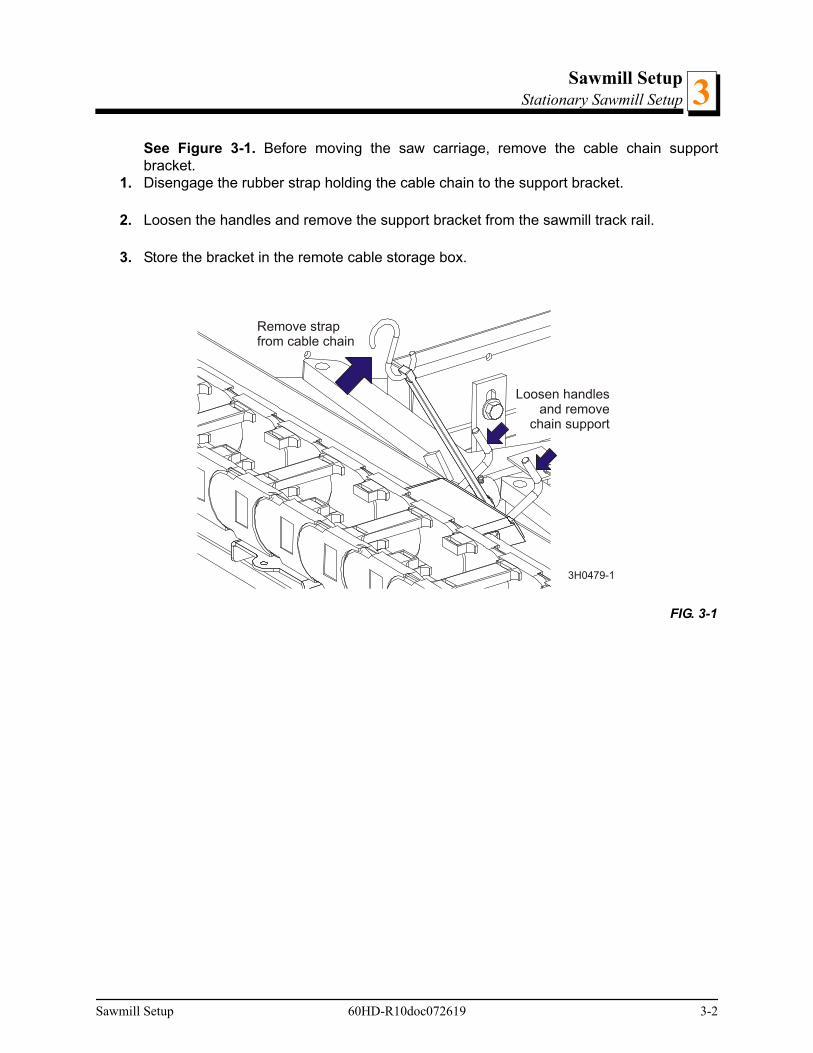
See Figure 3-1. Before moving the saw carriage, remove the cable chain supportbracket.
1. Disengage the rubber strap holding the cable chain to the support bracket.
2. Loosen the handles and remove the support bracket from the sawmill track rail.
3. Store the bracket in the remote cable storage box.
FIG. 3-1
3H0479-1
Remove strapfrom cable chain
Loosen handlesand remove
chain support
Sawmill Setup 60HD-R10doc072619 3-2

Sawmill SetupStationary Sawmill Setup3
Setup the control box prior to operating the sawmill.
See Figure 3-2.
4. Turn the locking handles holding the control box to the storage bracket counterclockwiseto loosen. Lift the control from the bracket and place on the stand. Tighten the lockinghandles by turning clockwise.
5. Place the control/stand assembly in the desired location. Open the cable storage box androute the cables to the back of the control box. Be sure the cables are clear of any movingparts of the sawmill and are not in the path where operator’s might trip on them. Connectthe cables to the box, matching the labels on the cables with the labels on the box (ie.,P1A to J1A, etc...).
FIG. 3-2
Storage Bracket
Control Box
Locking Handles
600098-5
3-3 60HD-R10doc072619 Sawmill Setup

Sawmill SetupStationary Sawmill Setup 3
See Figure 3-3.
6. Unhook the carriage safety chain, located at the bottom of the vertical mast.
1.
2. Start the engine to enable the battery-operated accessories (See Section 3.6). Use theup/down switch on the control panel to raise the cutting head from the carriage rest pin.
3. Remove the locking pin and swing the rest pin down below bed level.
NOTE: DC Models Only: Always make sure the engine is running before operating thesawmill controls. Operating the controls without the engine running will result in powerdrainage from the battery.
4. Use the carriage forward/reverse switch (left side of control box) to move the cutting headtoward the front (hitch end) of the mill.
5. Raise the side supports to prevent a log from falling off the side of the mill when loaded.
FIG. 3-3
Cable StorageBox
J1A to P1A
J2A to P2A
J3A to P3A
600084-2
Sawmill Setup 60HD-R10doc072619 3-4
Sawmill SetupStationary Sawmill Setup3
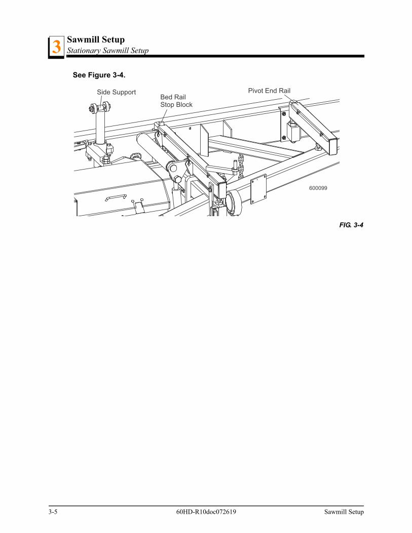
See Figure 3-4.
FIG. 3-4
600099
Side SupportBed RailStop Block
Pivot End Rail
3-5 60HD-R10doc072619 Sawmill Setup
Sawmill SetupStationary Sawmill Setup 3
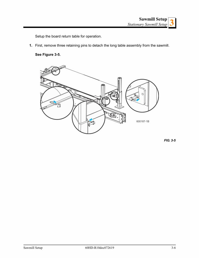
Setup the board return table for operation.
1. First, remove three retaining pins to detach the long table assembly from the sawmill.
See Figure 3-5.
FIG. 3-5
600187-1B
Sawmill Setup 60HD-R10doc072619 3-6

Sawmill SetupStationary Sawmill Setup3
2. Lift the long table assembly off the rest pin and slide toward the front of the mill. Rest thelong table on the short bottom table so it is balanced. Replace the three retaining pins.
3. Remove the rest pin retaining pin and pivot the rest pin down below bed level. Replacethe retaining pin.
See Figure 3-6.
FIG. 3-6
600187-2B
3-7 60HD-R10doc072619 Sawmill Setup

Sawmill SetupStationary Sawmill Setup 3
4. Pull the outrigger pins and lower the legs.
See Figure 3-7.
5. Slide the long table until it rests in position, level with the short table assembly.
6. If necessary, adjust the outrigger legs up or down so the table is level.
See Figure 3-8.
FIG. 3-7
FIG. 3-8
600187-3B
600187-4B
Sawmill Setup 60HD-R10doc072619 3-8
Sawmill SetupStationary Sawmill Setup3
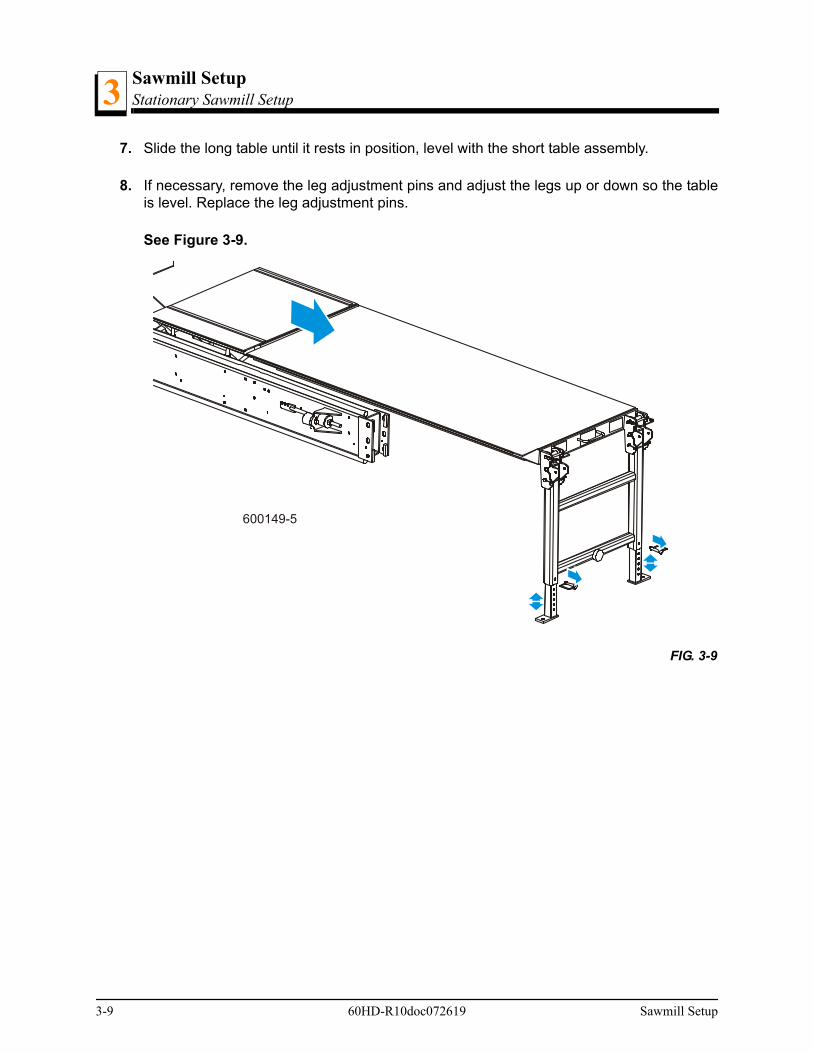
7. Slide the long table until it rests in position, level with the short table assembly.
8. If necessary, remove the leg adjustment pins and adjust the legs up or down so the tableis level. Replace the leg adjustment pins.
See Figure 3-9.
FIG. 3-9
600149-5
3-9 60HD-R10doc072619 Sawmill Setup

Sawmill SetupPortable Sawmill Setup 3
3.2 Portable Sawmill Setup
WARNING! Do not set up the mill on ground with more than a 10degree incline. If setup on an incline is necessary, put blocks underone side of the mill or dig out areas for outrigger legs to keep mill level.Setting up the mill on an incline could cause it to tip over, resulting inserious personal injury.
WARNING! Chock the trailer wheels to prevent movement beforeunhitching it from the towing vehicle. Failure to do so may result in seri-ous injury or death.
WARNING! Always make sure the trailer is supporting the sawmillframe when operating a sawmill with adjustable outriggers. Failure todo so may result in serious injury or death. The adjustable outriggersare intended to support the saw frame with assistance from the trailer.
WARNING! The adjustable outriggers supplied with portable sawmillsare not intended for setup on concrete or other hard surfaces.Long-term use of the adjustable outriggers on hard surfaces maycause the outriggers to fail, causing the sawmill to drop. This couldresult in possible serious injury or death.
If setting the sawmill up on concrete or other hard surface, replace theadjustable outrgger legs with stationary legs.
1. Unhitch the mill from the vehicle.
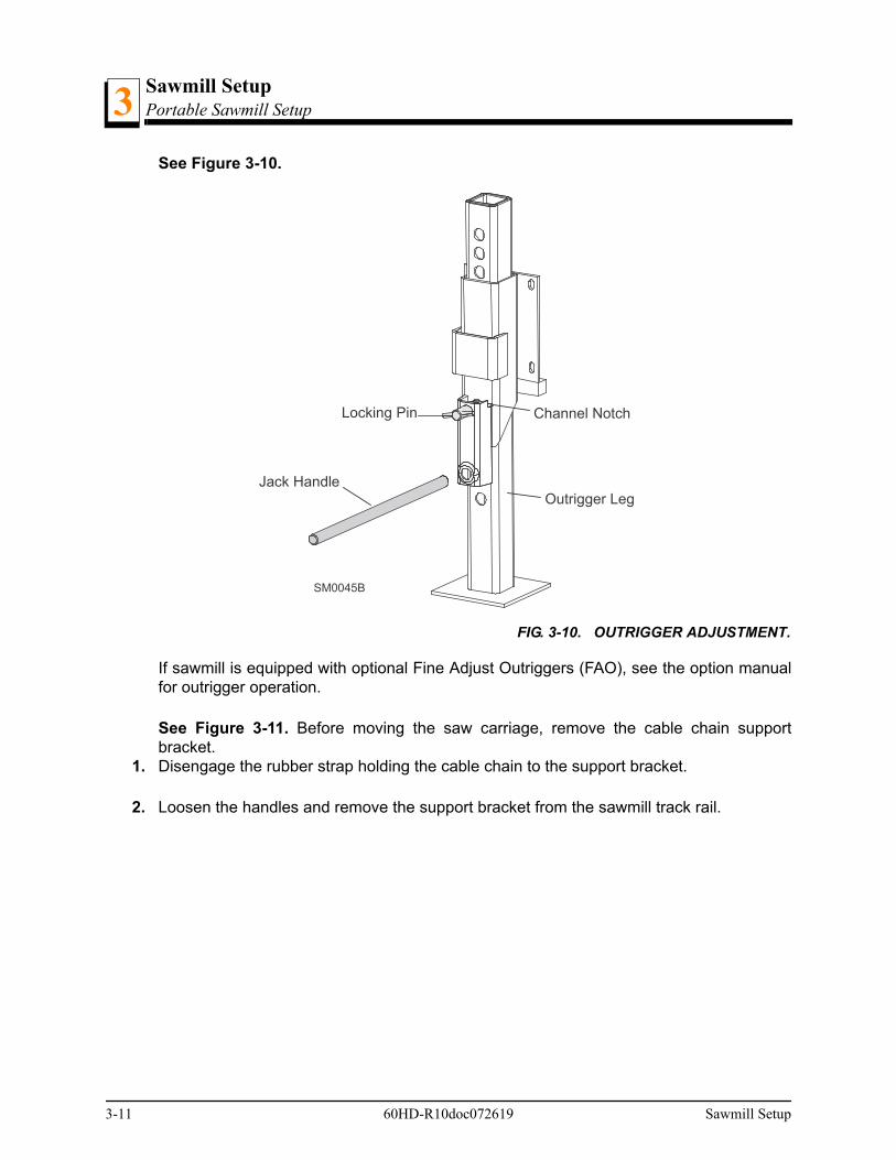
2. Lower and set the front three outriggers. To lower, use the provided jack handle to lift theweight from the locking pin. If necessary, rotate the locking pin counterclockwise so thatthe inner roll pin is free from the outrigger channel notch, then pull the locking pin out torelease the outrigger. Lower the outrigger as necessary. Push the locking pin back in andturn clockwise until the inner roll pin is behind the outrigger channel notch to “lock” theoutrigger in place.
WARNING! Put front outrigger down before moving cutting head fromthe rest position. Failure to do so may result in serious injury.
Sawmill Setup 60HD-R10doc072619 3-10
Sawmill SetupPortable Sawmill Setup3
See Figure 3-10.
If sawmill is equipped with optional Fine Adjust Outriggers (FAO), see the option manualfor outrigger operation.
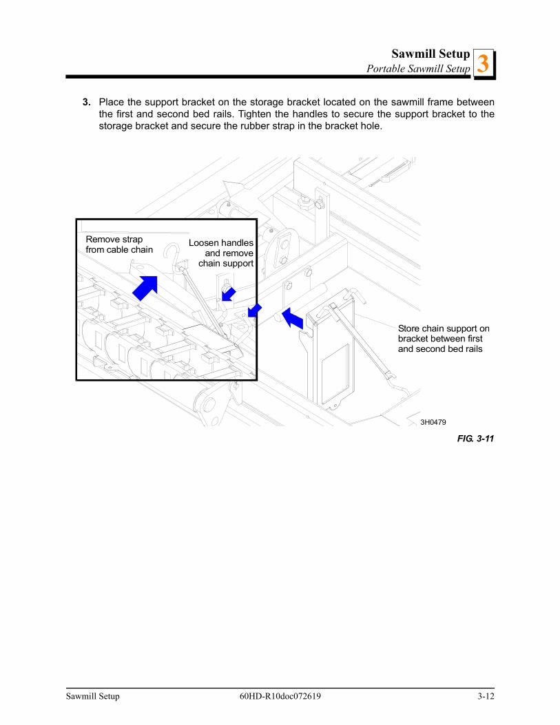
See Figure 3-11. Before moving the saw carriage, remove the cable chain supportbracket.
1. Disengage the rubber strap holding the cable chain to the support bracket.
2. Loosen the handles and remove the support bracket from the sawmill track rail.
FIG. 3-10. OUTRIGGER ADJUSTMENT.
SM0045B
Jack HandleOutrigger Leg
Channel NotchLocking Pin
3-11 60HD-R10doc072619 Sawmill Setup
Sawmill SetupPortable Sawmill Setup 3
3. Place the support bracket on the storage bracket located on the sawmill frame betweenthe first and second bed rails. Tighten the handles to secure the support bracket to thestorage bracket and secure the rubber strap in the bracket hole.
FIG. 3-11
Store chain support onbracket between firstand second bed rails
3H0479
Remove strapfrom cable chain
Loosen handlesand remove
chain support
Sawmill Setup 60HD-R10doc072619 3-12
Sawmill SetupPortable Sawmill Setup3
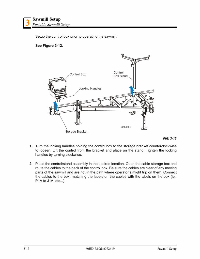
Setup the control box prior to operating the sawmill.
See Figure 3-12.
1. Turn the locking handles holding the control box to the storage bracket counterclockwiseto loosen. Lift the control from the bracket and place on the stand. Tighten the lockinghandles by turning clockwise.
2. Place the control/stand assembly in the desired location. Open the cable storage box androute the cables to the back of the control box. Be sure the cables are clear of any movingparts of the sawmill and are not in the path where operator’s might trip on them. Connectthe cables to the box, matching the labels on the cables with the labels on the box (ie.,P1A to J1A, etc...).
FIG. 3-12
Storage Bracket
Control Box
Locking Handles
600098-6
ControlBox Stand
3-13 60HD-R10doc072619 Sawmill Setup

Sawmill SetupPortable Sawmill Setup 3
See Figure 3-13.
1. Unhook the carriage safety chain, located at the bottom of the vertical mast.
2. Start the engine to enable the battery-operated accessories (See Section 3.6). Use theup/down switch on the control box to raise the cutting head from the carriage rest pin.Remove the locking pin and swing the rest pin down below bed level.
CAUTION! DC Models Only: Always make sure the engine is runningbefore operating the sawmill controls. Operating the controls withoutthe engine running will result in power drainage from the battery.
3. Remove the fenders by lifting them out of the slots.
CAUTION! To prevent fender damage, remove fenders before operat-ing sawmill or loading logs.
4. Use the feed control switch (left side of control box) to move the cutting head toward thefront end of the mill.
FIG. 3-13
Cable StorageBox
J1A to P1A
J2A to P2A
J3A to P3A
600084-2
Sawmill Setup 60HD-R10doc072619 3-14

Sawmill SetupPortable Sawmill Setup3
5. Lower and set the remaining rear outriggers. Level the sawmill by adjusting the outriggersto raise or lower each end of the sawmill. Adjust all outriggers evenly to avoid twisting themill frame by jacking one outrigger higher than the others.
For FAO(s), fine tune the outrigger base height as necessary. Move the cutting head tothe opposite end of the mill from the outrigger. Raise the entire outrigger (to remove thesawmill weight from it) and adjust the outrigger base as necessary. Lower the entire out-rigger and use the locking pin to secure in position.
CAUTION! Do not adjust the FAO outrigger base height while there isweight on the FAO. Damage to the FAO may result.
6. Raise the two side supports to prevent the log from falling off the side of the mill whenloaded.
See Figure 3-14.
Setup the board return table for operation.
FIG. 3-14
600099
Side SupportBed RailStop Block
Pivot End Rail
3-15 60HD-R10doc072619 Sawmill Setup
Sawmill SetupPortable Sawmill Setup 3
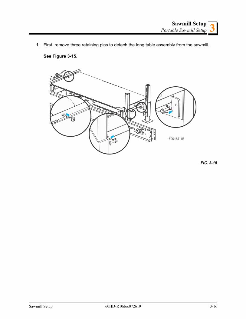
1. First, remove three retaining pins to detach the long table assembly from the sawmill.
See Figure 3-15.
FIG. 3-15
600187-1B
Sawmill Setup 60HD-R10doc072619 3-16
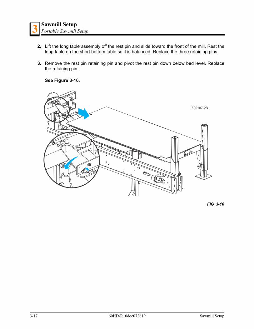
Sawmill SetupPortable Sawmill Setup3
2. Lift the long table assembly off the rest pin and slide toward the front of the mill. Rest thelong table on the short bottom table so it is balanced. Replace the three retaining pins.
3. Remove the rest pin retaining pin and pivot the rest pin down below bed level. Replacethe retaining pin.
See Figure 3-16.
FIG. 3-16
600187-2B
3-17 60HD-R10doc072619 Sawmill Setup
Sawmill SetupPortable Sawmill Setup 3
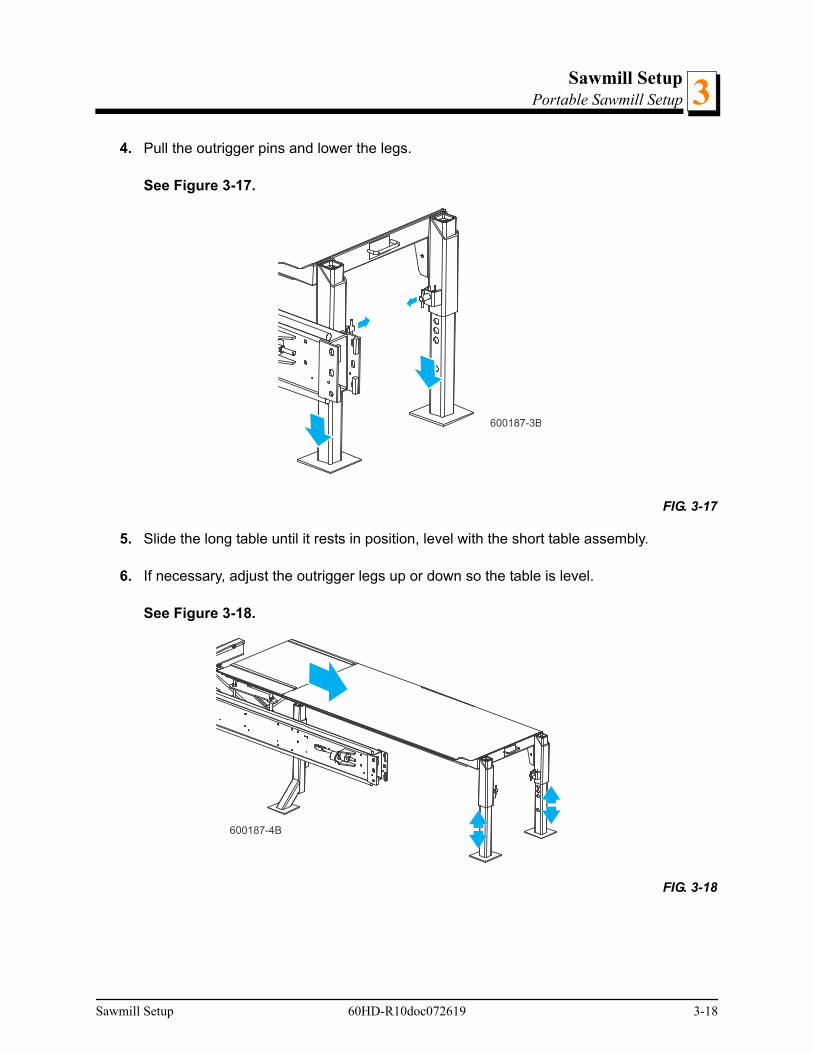
4. Pull the outrigger pins and lower the legs.
See Figure 3-17.
5. Slide the long table until it rests in position, level with the short table assembly.
6. If necessary, adjust the outrigger legs up or down so the table is level.
See Figure 3-18.
FIG. 3-17
FIG. 3-18
600187-3B
600187-4B
Sawmill Setup 60HD-R10doc072619 3-18
Sawmill SetupReplacing The Blade3
3.3 Replacing The Blade
DANGER! Always disengage the blade and shut off the sawmill enginebefore changing the blade. Failure to do so will result in serious injury.
WARNING! Always wear gloves and eye protection when handlingbandsaw blades. Changing blades is safest when done by one person!Keep all other persons away from area when coiling, carrying orchanging a blade. Failure to do so may result in serious injury.
1. Open the two blade housing covers that cover the blade wheels.
2. Turn the blade tension handle to release the blade tension until the wheel is pulled in andthe blade is lying loose in the blade housing.
3. Lift the blade out of the blade housing.
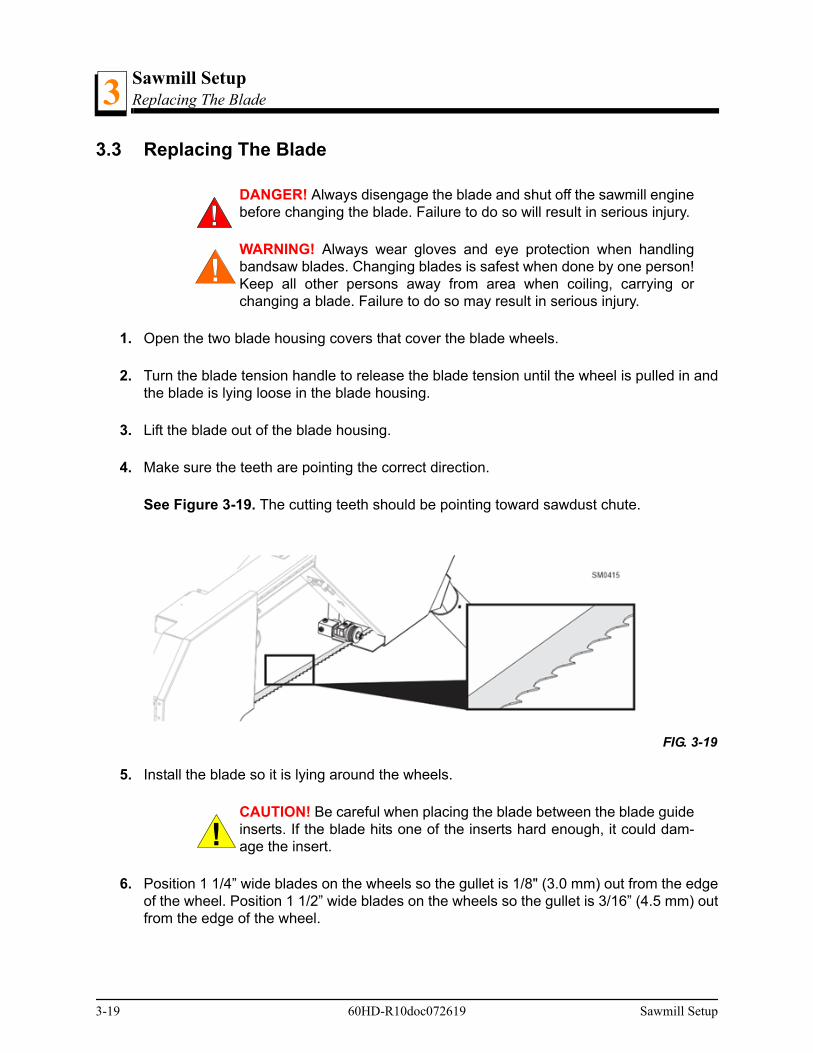
4. Make sure the teeth are pointing the correct direction.
See Figure 3-19. The cutting teeth should be pointing toward sawdust chute.
5. Install the blade so it is lying around the wheels.
CAUTION! Be careful when placing the blade between the blade guideinserts. If the blade hits one of the inserts hard enough, it could dam-age the insert.
6. Position 1 1/4” wide blades on the wheels so the gullet is 1/8" (3.0 mm) out from the edgeof the wheel. Position 1 1/2” wide blades on the wheels so the gullet is 3/16” (4.5 mm) outfrom the edge of the wheel.
FIG. 3-19
3-19 60HD-R10doc072619 Sawmill Setup

Sawmill SetupReplacing The Blade 3
NOTE: Revs prior to A8.01 only: Use the proper spacer behind theblade guide roller to position it properly to the blade. Rev. A7.02 -A8.00 or if blade guides retrofitted: Use 1/8” spacer 052364 for 11/2” blades or 1/4” spacer 041626 for 1 1/4” blades. Revisions priorto Rev. A7.02 with original blade guide design: Use no spacer for 11/2” blades or 1/8” spacer 052364 for 1 1/4” blades.
7. Close the blade housing covers.
8. Use the tension handle to tension the blade correctly.
Sawmill Setup 60HD-R10doc072619 3-20
Sawmill SetupTensioning The Blade3
3.4 Tensioning The Blade
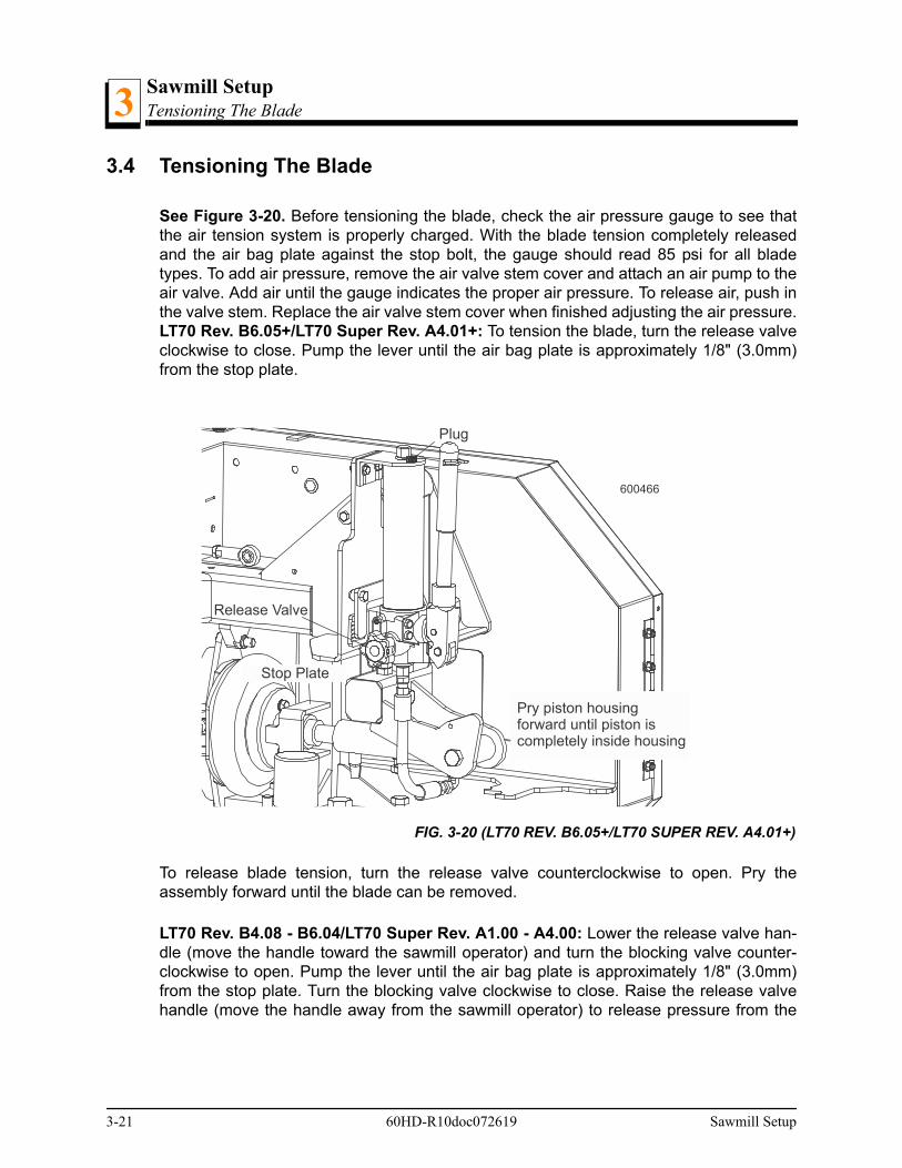
See Figure 3-20. Before tensioning the blade, check the air pressure gauge to see thatthe air tension system is properly charged. With the blade tension completely releasedand the air bag plate against the stop bolt, the gauge should read 85 psi for all bladetypes. To add air pressure, remove the air valve stem cover and attach an air pump to theair valve. Add air until the gauge indicates the proper air pressure. To release air, push inthe valve stem. Replace the air valve stem cover when finished adjusting the air pressure.LT70 Rev. B6.05+/LT70 Super Rev. A4.01+: To tension the blade, turn the release valveclockwise to close. Pump the lever until the air bag plate is approximately 1/8" (3.0mm)from the stop plate.
To release blade tension, turn the release valve counterclockwise to open. Pry theassembly forward until the blade can be removed.
LT70 Rev. B4.08 - B6.04/LT70 Super Rev. A1.00 - A4.00: Lower the release valve han-dle (move the handle toward the sawmill operator) and turn the blocking valve counter-clockwise to open. Pump the lever until the air bag plate is approximately 1/8" (3.0mm)from the stop plate. Turn the blocking valve clockwise to close. Raise the release valvehandle (move the handle away from the sawmill operator) to release pressure from the
FIG. 3-20 (LT70 REV. B6.05+/LT70 SUPER REV. A4.01+)
600466
Plug
Release Valve
Stop Plate
Pry piston housingforward until piston iscompletely inside housing
3-21 60HD-R10doc072619 Sawmill Setup

Sawmill SetupTensioning The Blade 3
pump. IMPORTANT! Do not exceed the limits as shown below when pumping the lever toavoid destroying the tensioner seal.
To release blade tension, turn the blocking valve counterclockwise to open and raise therelease valve handle. Place the handle between the end of the piston housing andbracket and pry the assembly forward until the blade can be removed.
Rev. A9.00 - B4.07: Adjust the valve handle to the closed (down) position. Install the ten-sioner handle to the tensioner and pump the lever until the air bag plate is approximately
FIG. 3-20
600354B
Release Valve Handle
BlockingValve
Stop Plate
Sawmill Setup 60HD-R10doc072619 3-22

Sawmill SetupTensioning The Blade3
1/8" (3.0mm) from the stop plate. Remove the tensioner handle and place in the storageposition on the tensioner assembly.
To release blade tension, adjust the valve handle to the open (up) position. Place the ten-sioner handle between the end of the piston housing and bracket and pry the assemblyforward until the blade can be removed.
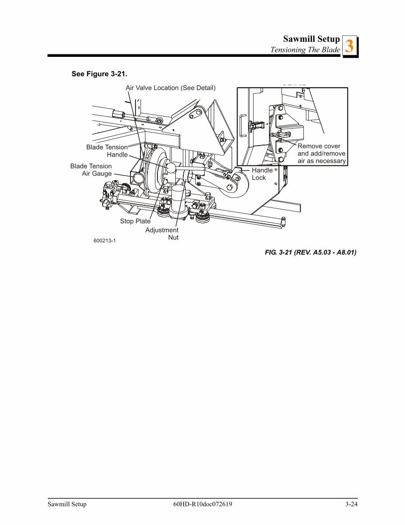
Rev. A5.03 - A8.01: To tension the blade, push the blade tension handle up. Make surethe handle lock flips to the locked (down) position after the blade tension is engaged.
WARNING! Use both hands to operate the blade tensioner handle. Besure the handle lock engages (flips down) after tensioning the blade.Failure to do so may result in injury.
Check that the air bag plate is approximately 1/8” (3.0mm) from the stop plate (or boltprior to Rev. A7.03). This should provide approximately 60 psi of blade tension for 1 1/4”blades or 80 psi for 1 1/2” and wider blades. If the gap to the stop plate is not 1/8”, releasethe blade tension by flipping the lock up and pulling the tension handle down. Be sure thehandle lock does not flip down when the tension handle is released. Turn the adjustmentnut clockwise to increase the stop plate gap, counterclockwise to decrease the gap.
FIG. 3-20 REV. A9.00 - B4.07
600239-4B
Valve Handle
TensionerHandle
Tensioner Handlein Storage Position
Open Valve toRelease BladeTension
Stop Plate
Use tensioner handleto pry piston housing
forward until bladecan be removed
3-23 60HD-R10doc072619 Sawmill Setup
Sawmill SetupTensioning The Blade 3
See Figure 3-21.
FIG. 3-21 (REV. A5.03 - A8.01)
Blade TensionHandle
Blade TensionAir Gauge
Air Valve Location (See Detail)
Remove coverand add/removeair as necessary
DETAIL
600213-1
Stop Plate
HandleLock
AdjustmentNut
Sawmill Setup 60HD-R10doc072619 3-24
Sawmill SetupTensioning The Blade3
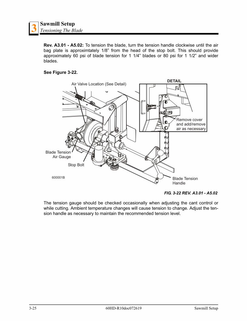
Rev. A3.01 - A5.02: To tension the blade, turn the tension handle clockwise until the airbag plate is approximtately 1/8” from the head of the stop bolt. This should provideapproximately 60 psi of blade tension for 1 1/4” blades or 80 psi for 1 1/2” and widerblades.
See Figure 3-22.
The tension gauge should be checked occasionally when adjusting the cant control orwhile cutting. Ambient temperature changes will cause tension to change. Adjust the ten-sion handle as necessary to maintain the recommended tension level.
FIG. 3-22 REV. A3.01 - A5.02
Blade TensionHandle
Blade TensionAir Gauge
Air Valve Location (See Detail)
Remove coverand add/removeair as necessary
DETAIL
600001B
Stop Bolt
3-25 60HD-R10doc072619 Sawmill Setup
Sawmill SetupTracking The Blade 3
3.5 Tracking The Blade
1. Make sure the blade housing covers are closed and all persons are clear of the open sideof the saw head.
2. Start the engine (or motor).
3. Engage the blade, rotating the blade until the blade positions itself on the wheels.
WARNING! Do not spin the blade wheels by hand. Spinning the bladewheels by hand may result in serious injury.
4. Disengage the blade. Turn off the engine, remove the key and check the position of theblade on the blade wheels.
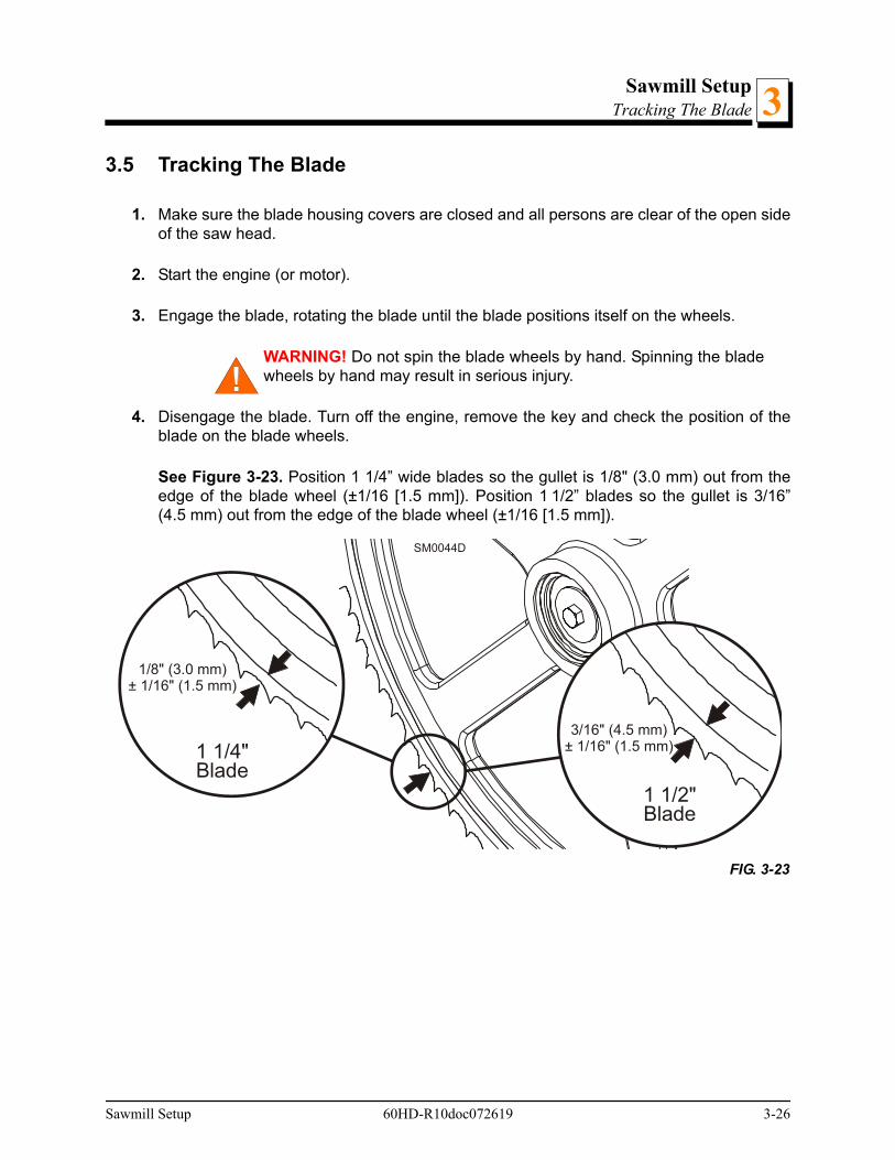
See Figure 3-23. Position 1 1/4” wide blades so the gullet is 1/8" (3.0 mm) out from theedge of the blade wheel (±1/16 [1.5 mm]). Position 1 1/2” blades so the gullet is 3/16”(4.5 mm) out from the edge of the blade wheel (±1/16 [1.5 mm]).
FIG. 3-23
SM0044D
3/16" (4.5 mm)± 1/16" (1.5 mm)
1 1/2"Blade
1/8" (3.0 mm)± 1/16" (1.5 mm)
1 1/4"Blade
Sawmill Setup 60HD-R10doc072619 3-26

Sawmill SetupTracking The Blade3
5. Use the cant adjustment bolt to adjust where the blade travels on the blade wheels.
See Figure 3-1.
To move the blade out on the blade wheel, turn the cant adjustment bolt clockwise. Tomove the blade in on the blade wheel, turn the bolt counterclockwise.
NOTE: Slight adjustments of the side bolts on the outer blade wheelare usually all that is necessary to track the blade properly. See Sec-tion 7.2 for complete blade wheel alignment instructions.
6. Close the blade housing covers, retension the blade and spin the blade again. Repeatthis procedure until the blade tracks on the blade wheels properly.
7. Adjust the blade tension if necessary to compensate for any changes that may haveoccured while adjusting the cant control.
DANGER! Make sure all guards and covers are in place and securedbefore operating or towing the sawmill. Failure to do so may result inserious injury. Be sure the blade housing and pulley covers are inplace and secure.
IMPORTANT! After aligning the blade on the wheels, always dou-ble-check the blade guide spacing and location. (See Section SEC-TION 7 for more information.)
FIG. 3-1
600001-1B
Cant Adjustment Bolt(See Detail)
DETAIL
Turn bolt clockwiseto move blade out on wheel;counterclockwise tomove blade in on wheel
3-27 60HD-R10doc072619 Sawmill Setup
Sawmill SetupStarting The Engine (or Motor)
Sawmill Setup 60HD-R10doc072619 3-28
33.6 Starting The Engine (or Motor)
See the appropriate manual supplied with your specific engine/motor configuration forstarting and operating instructions.
DANGER! Make sure all guards and covers are in place and securedbefore operating or towing the sawmill. Failure to do so may result inserious injury. Be sure the blade housing and pulley covers are inplace and secure.
DANGER! Always be sure the blade is disengaged and all persons areout of the path of the blade before starting the engine or motor. Failureto do so will result in serious injury.
WARNING! Always wear eye, ear, respiration, and foot protectionwhen operating the sawmill. Failure to do so may result in seriousinjury.
WARNING! Be sure the power feed switch (if equipped) is in the neu-tral position before turning the key switch to the on (#1) or accessory(#3) position. This prevents accidental carriage movement which maycause serious injury or death.
Sawmill SetupBoard Return3
3.7 Board Return
WARNING! The automatic board return is intended to assist a secondoperator in removing boards quickly. Do not use the board return whenoperating the sawmill alone. Serious injury, death or damage to theequipment may result.
WARNING! Never use the board return table as a platform to stand on.This table is designed and intended to assist in the removal of boardsonly. Standing on the table may result in serious injury.
The sawmill is equipped with a board return system. This system consists of arms on thesaw head and a board return table to catch the board as it is removed from the log. Use ofthe board return not recommended with material shorter than 8 foot.
When the blade reaches the end of the log, the arms will drop down to catch the boardand drag it back toward the operator as the saw head is returned.
DANGER! Keep all persons out of the path of returning boards. Failureto do so will result in serious injury.
Boards may not always return in the same path or location. If a board returns in a mannerthat does not allow the sawyer or off-bearer to maintain control, it may be necessary tostop the reverse motion of the saw head.
When the board return is to be used, a second person is required to remove the board asit is returned. DO NOT attempt to use the board return feature when sawing alone.
3-29 60HD-R10doc072619 Sawmill Setup
Sawmill SetupBoard Return 3
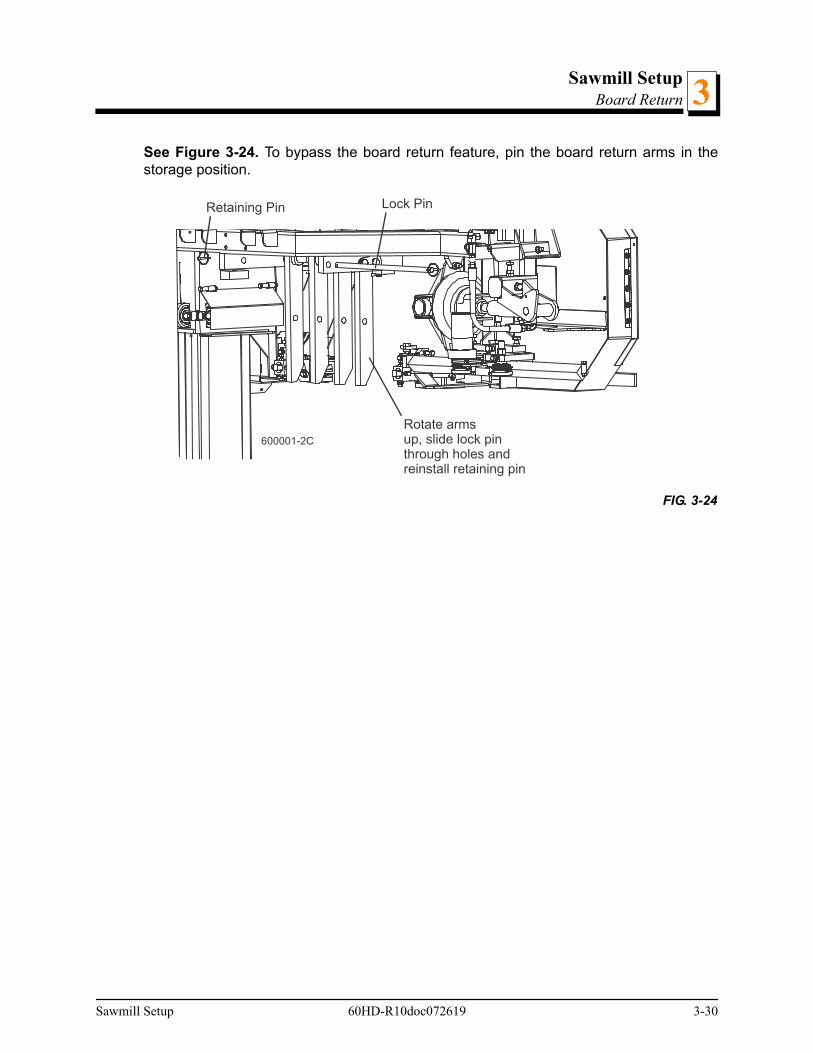
See Figure 3-24. To bypass the board return feature, pin the board return arms in thestorage position.
FIG. 3-24
600001-2C
Retaining Pin Lock Pin
Rotate armsup, slide lock pinthrough holes andreinstall retaining pin
Sawmill Setup 60HD-R10doc072619 3-30
Sawmill OperationHydraulic Control Operation4
SECTION 4 SAWMILL OPERATION
4.1 Hydraulic Control Operation
AC sawmill: The hydraulic controls are operational when the key switch is on exceptwhen the saw carriage is moving forward.
DC & 550-600V AC sawmill: The hydraulic control levers become operational when thecontacts at the bottom of the carriage touch the power strip on the frame tube. Thehydraulic control levers will only work when the cutting head is close enough to the frontend of the mill to touch the power strip. On remote mills after Rev. A5.00, a second powerstrip is located at the rear of sawmill frame to allow operation of the hydraulic clamp, sidesupports and toe boards with the cutting head at the rear of the mill. Avoid high-currentoperations such as loading or turning logs unless the saw head is in contact with the frontpower strip.
Hydraulic units have seven control levers to load, clamp, turn and level logs.Use thehydraulic control levers to get the mill ready to load a log.
DANGER! Keep all persons out of the path of moving equipment andlogs when operating sawmill or loading and turning logs. Failure to doso will result in serious injury.
CAUTION! Always make sure the engine is running before operatingthe hydraulic controls. Operating the controls without the engine run-ning will result in power drainage from the battery. Holding the hydrau-lic switches halfway up or down also will cause excessive drainagefrom the battery.
1. Move the clamp out and down so it will not get in the way of logs being loaded onto thebed.
Lower the clamp in/out lever to move the clamp out toward the loading side of the saw-mill.
Lower the clamp up/down lever to lower the clamp below bed level.
2. Raise the log loader lever to extend the legs of the log loader out as far as they will go.
3. Wide Head Models Only: Remove the loading arm lock pin securing the log loadingarms in the travel position.
4-1 60HD-R10doc072619 Sawmill Operation

Sawmill OperationHydraulic Control Operation 4
See Figure 4-1.
4. The chain securing the log loading arm to the log turner arm will be tight. Raise the logturner lever to raise the turner arm until there is slack in the chain.
5. Unchain the loading arm from the turner arm.
6. Lower the turner lever to completely lower the turner arm. Notice that after the turner armis all the way down, the side support braces will begin to lower. Release the turner leverafter the turner arm is lowered, but before the side supports begin to lower. This stops thelog being loaded from damaging the turner and/or falling off the side of the sawmill.
7. When raising the turner lever, the side supports rise first. After reaching a fully verticalposition, the turner arm will engage and start to rise.
8. Manually lower the log loader so it rests on the ground.
CAUTION! Be careful when manually lowering the log loader. Do notdrop the loader onto the ground or perform any action which mightbreak the velocity fuse valves on the loader cylinders. These valvescontrol hydraulic flow and are necessary to prevent the loading armfrom collapsing during use.
9. Lower the loader lever to lower the loading arm as far as it will go. Logs must be rolledonto the loading arm one at a time for loading onto the bed of the mill.
10. The front and rear toe boards should be below bed level. Once a tapered log has beenloaded, the front or rear end of the log may be lifted to parallel the heart of the log to thepath of the blade.
FIG. 4-1
3H1176-1B
Sawmill Operation 60HD-R10doc072619 4-2

Sawmill OperationHydraulic Control Operation4
The front toe board is raised by lifting the front toe board lever up. The rear toe board israised by lifting the rear toe board lever up. Once a flat has been made and the log isready to be turned, push the appropriate toe board lever down to lower either toe boarduntil it falls below the level of the bed.
4-3 60HD-R10doc072619 Sawmill Operation
Sawmill OperationLoading, Turning And Clamping Logs 4
4.2 Loading, Turning And Clamping Logs
TO LOAD LOGS
1. Start the engine and move the saw carriage to the front end of the frame.
CAUTION! Before loading a log, be sure the cutting head is moved farenough forward so the log does not hit it. Failure to do so may result inmachine damage.
CAUTION! Be sure the log clamp, pivot rails, turning arm and toeboards are adjusted out of the path of the log before loading a log ontothe bed. Failure to do so may result in machine damage or cause mis-alignment.
2. Raise the side supports on the sawmill bed to prevent the log from falling off the side ofthe bed.
3. Use cant hooks or loading equipment to move the log to the foot of the loading arms.
4. Roll the log onto the loader so that it is approximately centered with the sawmill bed. Thelog turner will operate much easier if the log is centered on the sawmill bed.
DANGER! Keep all persons out of the path of moving equipment andlogs when operating sawmill or loading and turning logs. Failure to doso will result in serious injury.
5. Raise the loader to lift the log onto the sawmill bed. Simply let the loader rise until the logrolls onto the mill bed.
6. Raise the clamp up to prevent the log from rolling off the bed.
7. Clamp the log and lower the loading arm. Leave the loading arm about halfway up whilesquaring the log. This will stop the log from rolling off the side of the mill.
WARNING! Always leave loading arm halfway up while log is on saw-mill bed. Failure to do so may result in serious injury or death.
NOTE: Logs also may be loaded onto the mill with a tractor or other equipment specifi-cally designed for that purpose.
Sawmill Operation 60HD-R10doc072619 4-4

Sawmill OperationLoading, Turning And Clamping Logs4
TO TURN LOGS
1. Engage the log turner arm. Let the arm rise until it touches the log.
2. Spin the log against the side supports until it is turned the way you want it for the first cut.
TO TURN LOGS (OPTIONAL PROCEDURE)
If you are turning a small cant on a mill with two-plane clamp, you may opt to use theclamp to turn the cant.
1. Lower the clamp below bed level.
2. Move the clamp in, beneath the edge of the cant.
3. Raise the clamp and flip the cant.
TO CLAMP LOGS
1. Clamp the log against the side supports.
2. Lower the turner until the arm falls below the bed.
3. When the turner arm is lowered all the way, the side supports will begin to lower. Back theclamp off slightly, and let the side supports come down until they are positioned below thelevel of your first few cuts.
TO LEVEL A TAPERED LOG
Raise the front or rear toe board until the heart of the log measures the same distancefrom the bed rails at each end of the log.
4-5 60HD-R10doc072619 Sawmill Operation

Sawmill OperationUp/Down Operation
Sawmill Operation 60HD-R10doc072619 4-6
44.3 Up/Down Operation
This section describes operation of the up/down system with the standard controls. Seethe operation section of the Accuset 2 manual for alternate instructions for operating theup/down system.
1. Install a blade, if needed, and check for correct blade tension. (See Section 3.3).
2. Set the cutting head to the desired height. (The blade height scale shows the height of theblade above the bed rails.)
See Figure 4-2. The up/down switch is located on the right side of the control panel. Usethe switch to raise or lower the cutting head. Hold the switch in position until the cuttinghead reaches the desired height, then release.
The up/down switch is designed to return to the neutral or "off" position when released. Ifthe switch remains engaged, manually move the switch to the neutral or "off" position.Repair the up/down switch (See Section 6.2).
CAUTION! Always make sure the up/down switch moves to the neutralor “off” position when released to ensure that the saw head stops mov-ing. Failure to do so may result in machine damage.
CAUTION! DO NOT try to force the carriage above the 35" (88 cm)mark or below the 1" (2.54 cm) mark. Damage to the up/down systemmay result.
FIG. 4-2
3H0278B
Cutting HeadUp
Cutting HeadDown
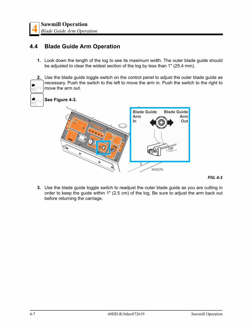
Sawmill OperationBlade Guide Arm Operation4
4-7 60HD-R10doc072619 Sawmill Operation
4.4 Blade Guide Arm Operation
1. Look down the length of the log to see its maximum width. The outer blade guide shouldbe adjusted to clear the widest section of the log by less than 1" (25.4 mm).
2. Use the blade guide toggle switch on the control panel to adjust the outer blade guide asnecessary. Push the switch to the left to move the arm in. Push the switch to the right tomove the arm out.
See Figure 4-3.
3. Use the blade guide toggle switch to readjust the outer blade guide as you are cutting inorder to keep the guide within 1" (2.5 cm) of the log. Be sure to adjust the arm back outbefore returning the carriage.
FIG. 4-3
3H0279
Blade GuideArmIn
Blade GuideArmOut
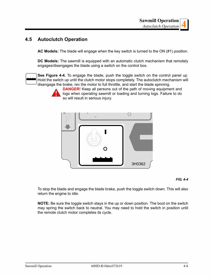
Sawmill OperationAutoclutch Operation
Sawmill Operation 60HD-R10doc072619 4-8
44.5 Autoclutch Operation
AC Models: The blade will engage when the key switch is turned to the ON (#1) position.
DC Models: The sawmill is equipped with an automatic clutch mechanism that remotelyengages/disengages the blade using a switch on the control box.
See Figure 4-4. To engage the blade, push the toggle switch on the control panel up.Hold the switch up until the clutch motor stops completely. The autoclutch mechanism willdisengage the brake, rev the motor to full throttle, and start the blade spinning.
DANGER! Keep all persons out of the path of moving equipment andlogs when operating sawmill or loading and turning logs. Failure to doso will result in serious injury.
To stop the blade and engage the blade brake, push the toggle switch down. This will alsoreturn the engine to idle.
NOTE: Be sure the toggle switch stays in the up or down position. The boot on the switchmay spring the switch back to neutral. You may need to hold the switch in position untilthe remote clutch motor completes its cycle.
FIG. 4-4
3H0362
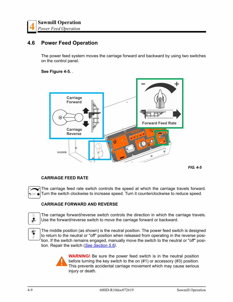
Sawmill OperationPower Feed Operation4
4.6 Power Feed Operation
The power feed system moves the carriage forward and backward by using two switcheson the control panel.
See Figure 4-5. .
.
CARRIAGE FEED RATE
The carriage feed rate switch controls the speed at which the carriage travels forward.Turn the switch clockwise to increase speed. Turn it counterclockwise to reduce speed.
CARRIAGE FORWARD AND REVERSE
The carriage forward/reverse switch controls the direction in which the carriage travels.Use the forward/reverse switch to move the carriage forward or backward.
The middle position (as shown) is the neutral position. The power feed switch is designedto return to the neutral or "off" position when released from operating in the reverse posi-tion. If the switch remains engaged, manually move the switch to the neutral or "off" posi-tion. Repair the switch (See Section 5.6).
WARNING! Be sure the power feed switch is in the neutral positionbefore turning the key switch to the on (#1) or accessory (#3) position.This prevents accidental carriage movement which may cause seriousinjury or death.
FIG. 4-5
3H0280B
CarriageReverse
CarriageForward
Forward Feed Rate
4-9 60HD-R10doc072619 Sawmill Operation
Sawmill OperationPower Feed Operation 4
USING THE POWER FEED
1. To move the carriage forward, push the forward/reverse switch forward and turn the feedrate switch clockwise.
HINT: To get a straight cut in the first part of the board, feed the blade into the log at aslow speed. This stops the blade from flexing and dipping up or down. Turn the carriagefeed rate switch to a slow speed until the whole width of the blade has entered the cut.Then use the carriage feed rate switch to increase the feed rate as desired. Maximumfeed rate varies with width and hardness of the wood. Over-feeding results in engine andblade wear, and also produces a wavy cut.
2. Stop the carriage at the end of the cut by turning the carriage feed rate switch counter-clockwise until the carriage stops moving. DC Models Only: Throw the autoclutch toggleswitch down to stop the blade and drop the engine to idle. Remove the board from the topof the log. Always disengage the blade before returning the carriage for the nextcut.
CAUTION! DC Models Only: Be sure to stop the blade when return-ing the carriage. This will not only prevent the blade from being pulledoff and ruined by a wood sliver, but also will increase the life of theblade. See Section 4.9 for optional sawing procedure.
AC Models Only: The blade will continue to spin as long as the blade motor is on. Usethe optional sawing procedure described in Section 4.9 Optional Cutting Procedure.
3. Make sure that the blade does not catch on the end of the log. Raise the carriage slightlyto make sure the blade clears the log when returned.
4. Return the carriage to the front of the mill by pushing the forward/reverse switch down.The power feed motor will bypass the carriage feed rate switch and the carriage will auto-matically return at the fastest speed available. See Section 4.9 for optional sawing proce-dure.
HINT: Try to stop the blade while the heel of the blade is still on the log. Then bring thecarriage back without adjusting the blade up. This lets you keep the blade at the currentheight setting so you can make the next blade height adjustment more quickly.
DANGER! Stay clear of the area between the trailer axle and saw car-riage. Failure to do so will result in serious injury.
Sawmill Operation 60HD-R10doc072619 4-10
Sawmill OperationCutting The Log4
4-11 60HD-R10doc072619 Sawmill Operation
4.7 Cutting The Log
1. Once the log is placed where you want it and clamped firmly, move the saw head to posi-tion the blade close to the end of the log.
2. Use the blade height scale to determine where to make your first cut (See Section 4.10).The blade height scale will help you to do this. Set the blade to the desired height with theup/down switch. Make sure that the blade will clear all side supports and the clamp.Adjust the outer blade guide to clear the widest section of the log by moving the bladeguide toggle switch.
NOTE: An optional laser sight is available to help determine where the blade will travelthrough the log. See the laser sight manual for detailed operating instructions.
3. DC Models Only: Engage the autoclutch blade switch to start the blade spinning.
4. Start the water lube if necessary to prevent sap buildup on the blade. See Section 4.11.
5. Feed the blade into the log slowly (See Section 4.6). Once the blade completely entersthe log, increase the feed rate as desired. Always try to cut at the fastest speed you canwhile keeping an accurate cut. Cutting too slowly will waste blade life and lower produc-tion!
6. As you get to the end of the log, slow down the feed rate. When the teeth exit the end ofthe log, stop the carriage. DC Models Only: Disengage the autoclutch blade switch.Remove the slab that you have just cut from the log.
7. Use the carriage forward/reverse switch to return the carriage to the front of the mill.
8. Repeat until the first side of the log is cut as desired. Set aside the usable flitches (boardswith bark on one or both sides). You can edge them on the mill later.
9. Lower the toe boards, if they were used. Use the hydraulic levers to release the clampand engage the log turner. Turn the log 90 or 180 degrees. Make sure the flat on the log isplaced flat against side supports if turned 90 degrees. Make sure it is placed on bed railsif turned 180 degrees. If the log was turned 90 degrees and you are using toe boards tocompensate for taper in the log, raise the front or rear toe board again on the second sideof the log until the heart is parallel with the bed.
10. Repeat the steps used to cut the first side of the log until the log is square. Cut boardsfrom the remaining cant by adjusting the blade height for the thickness of boards that youwant.
Example: Remember that the blade cuts a 1/16 - 1/8" (1.6-3.2 mm) wide kerf. If you want1" (25.4 mm) thick boards, lower the carriage 1 1/16 - 1 1/8" (27-28.6 mm) for each board.

Sawmill OperationEdging
Sawmill Operation 60HD-R10doc072619 4-12
44.8 Edging
1. Raise the side supports to 1/2 the height of the flitches, or the boards that need to beedged.
2. Stack the flitches on edge against the side supports.
3. Clamp the flitches against the side supports halfway up the flitch height. (Wider flitchesshould be placed to the clamp side. When they are edged, flip them over to edge the sec-ond side without disturbing the other flitches or without having to pull them from the mid-dle of the stack).
4. Adjust the blade height to edge a few of the widest boards.
5. Loosen the clamp and turn the edged boards over to edge the other side.
6. Repeat steps 2-4.
7. Loosen the clamp and remove the boards that have good clean edges on both sides.Clamp the remaining flitches and repeat steps 2-5.
Sawmill OperationOptional Cutting Procedure4
4-13 60HD-R10doc072619 Sawmill Operation
4.9 Optional Cutting Procedure
In order to achieve maximum production rates, it may be desirable to leave the bladeengaged when returning the carriage. (Normal operation procedures recommend disen-gaging the blade before returning the carriage for maximum blade life and fuel economy.)
DANGER! If leaving the blade engaged for maximum pro-duction rates, make sure the off-bearer stays out of the pathof the blade. Failure to do so will result in serious injury ordeath.
CAUTION! If you choose to leave the blade engaged; raisethe blade to clear the log before returning the carriage. Fail-ure to do so may cause damage to the blade and/or saw-mill.
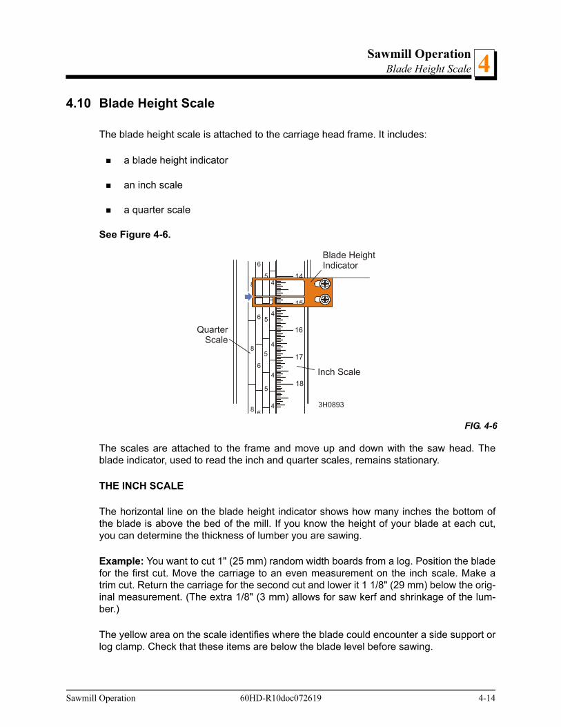
Sawmill OperationBlade Height Scale 4
4.10 Blade Height Scale
The blade height scale is attached to the carriage head frame. It includes:
a blade height indicator
an inch scale
a quarter scale
See Figure 4-6.
The scales are attached to the frame and move up and down with the saw head. Theblade indicator, used to read the inch and quarter scales, remains stationary.
THE INCH SCALE
The horizontal line on the blade height indicator shows how many inches the bottom ofthe blade is above the bed of the mill. If you know the height of your blade at each cut,you can determine the thickness of lumber you are sawing.
Example: You want to cut 1" (25 mm) random width boards from a log. Position the bladefor the first cut. Move the carriage to an even measurement on the inch scale. Make atrim cut. Return the carriage for the second cut and lower it 1 1/8" (29 mm) below the orig-inal measurement. (The extra 1/8" (3 mm) allows for saw kerf and shrinkage of the lum-ber.)
The yellow area on the scale identifies where the blade could encounter a side support orlog clamp. Check that these items are below the blade level before sawing.
FIG. 4-6
15
16
17
18
144
4
4
4
4
5
5
5
5
6
6
6
6
8
8
8
Blade HeightIndicator
Inch Scale
QuarterScale
3H0893
Sawmill Operation 60HD-R10doc072619 4-14
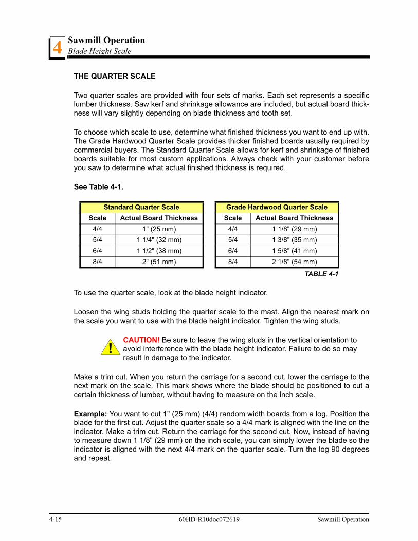
Sawmill OperationBlade Height Scale4
THE QUARTER SCALE
Two quarter scales are provided with four sets of marks. Each set represents a specificlumber thickness. Saw kerf and shrinkage allowance are included, but actual board thick-ness will vary slightly depending on blade thickness and tooth set.
To choose which scale to use, determine what finished thickness you want to end up with.The Grade Hardwood Quarter Scale provides thicker finished boards usually required bycommercial buyers. The Standard Quarter Scale allows for kerf and shrinkage of finishedboards suitable for most custom applications. Always check with your customer beforeyou saw to determine what actual finished thickness is required.
See Table 4-1.
To use the quarter scale, look at the blade height indicator.
Loosen the wing studs holding the quarter scale to the mast. Align the nearest mark onthe scale you want to use with the blade height indicator. Tighten the wing studs.
CAUTION! Be sure to leave the wing studs in the vertical orientation toavoid interference with the blade height indicator. Failure to do so mayresult in damage to the indicator.
Make a trim cut. When you return the carriage for a second cut, lower the carriage to thenext mark on the scale. This mark shows where the blade should be positioned to cut acertain thickness of lumber, without having to measure on the inch scale.
Example: You want to cut 1" (25 mm) (4/4) random width boards from a log. Position theblade for the first cut. Adjust the quarter scale so a 4/4 mark is aligned with the line on theindicator. Make a trim cut. Return the carriage for the second cut. Now, instead of havingto measure down 1 1/8" (29 mm) on the inch scale, you can simply lower the blade so theindicator is aligned with the next 4/4 mark on the quarter scale. Turn the log 90 degreesand repeat.
Standard Quarter Scale Grade Hardwood Quarter Scale
Scale Actual Board Thickness Scale Actual Board Thickness
4/4 1" (25 mm) 4/4 1 1/8" (29 mm)
5/4 1 1/4" (32 mm) 5/4 1 3/8" (35 mm)
6/4 1 1/2" (38 mm) 6/4 1 5/8" (41 mm)
8/4 2" (51 mm) 8/4 2 1/8" (54 mm)
TABLE 4-1
4-15 60HD-R10doc072619 Sawmill Operation

Sawmill OperationWater Lube Operation 4
4.11 Water Lube Operation
The Water Lube System keeps the blade clean. Water flows from a 5-gallon (18.9 liter)bottle through a hose to the blade guide where the blade enters the log. A valve in thebottle cap controls the amount of water flow.
See Figure 4-7.
Not all types of wood require the use of the Water Lube System. When it is needed, usejust enough water to keep the blade clean. This saves water, and lowers the risk of stain-ing the boards with water. Usual flow will be 1-2 gallons (3.8-7.6 liters) per hour.
Before removing the blade, engage the blade. Let the blade spin with water running on itfor about 15 seconds. This will clean the blade of sap buildup. Wipe the blade dry with arag before storing or sharpening.
For further lubrication benefits, add one 12oz. (0.35L) bottle of Wood-Mizer Lube Additiveto 5 gallons (18.9 liters) of water. Wood-Mizer Lube Additive enables some previouslyimpossible timbers to be cut by significantly reducing resin buildup on the blade. It helpsto reduce heat buildup, wavy cuts, and blade noise. This biodegradable and environmen-tally friendly pre-mix includes a water softener additive, so it works with hard water.
FIG. 4-7
Turn valve counterclockwiseto open; Clockwise to close
3H0129
Sawmill Operation 60HD-R10doc072619 4-16

Sawmill OperationWater Lube Operation4
WARNING! Use ONLY water and Wood-Mizer Lube Additive with thewater lube accessory. Never use flammable fuels or liquids such asdiesel fuel. If these types of liquids are necessary to clean the blade,remove it and clean with a rag. Failure to do so can damage the equip-ment and may result in serious injury or death.
CAUTION! Use windshield washer fluid to the water tank and prime asrecommended when sawing or storing thesawmill in below-freezingtemperatures. Use windshield washer fluid with a freezing point of atleast -20°F (-29°C). Failure to do so may cause damage to the LubeM-izer system.
See the separate LubeMizer System manual for operation instructions.
4-17 60HD-R10doc072619 Sawmill Operation
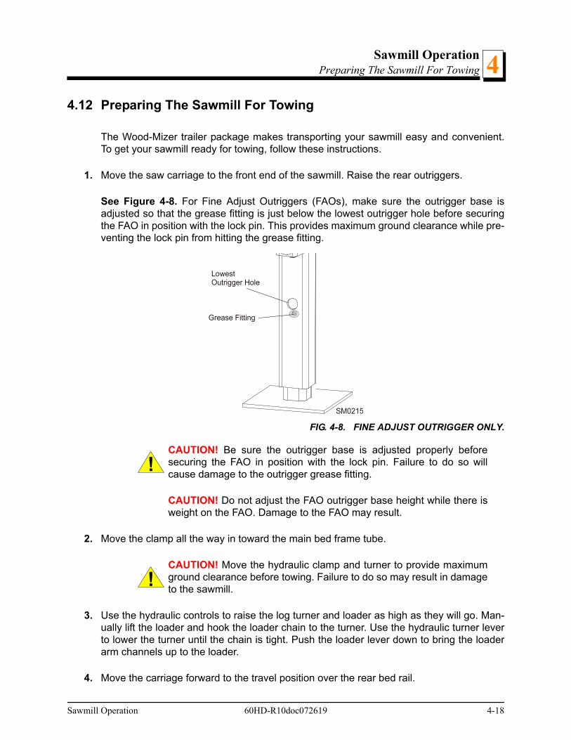
Sawmill OperationPreparing The Sawmill For Towing 4
4.12 Preparing The Sawmill For Towing
The Wood-Mizer trailer package makes transporting your sawmill easy and convenient.To get your sawmill ready for towing, follow these instructions.
1. Move the saw carriage to the front end of the sawmill. Raise the rear outriggers.
See Figure 4-8. For Fine Adjust Outriggers (FAOs), make sure the outrigger base isadjusted so that the grease fitting is just below the lowest outrigger hole before securingthe FAO in position with the lock pin. This provides maximum ground clearance while pre-venting the lock pin from hitting the grease fitting.
CAUTION! Be sure the outrigger base is adjusted properly beforesecuring the FAO in position with the lock pin. Failure to do so willcause damage to the outrigger grease fitting.
CAUTION! Do not adjust the FAO outrigger base height while there isweight on the FAO. Damage to the FAO may result.
2. Move the clamp all the way in toward the main bed frame tube.
CAUTION! Move the hydraulic clamp and turner to provide maximumground clearance before towing. Failure to do so may result in damageto the sawmill.
3. Use the hydraulic controls to raise the log turner and loader as high as they will go. Man-ually lift the loader and hook the loader chain to the turner. Use the hydraulic turner leverto lower the turner until the chain is tight. Push the loader lever down to bring the loaderarm channels up to the loader.
4. Move the carriage forward to the travel position over the rear bed rail.
FIG. 4-8. FINE ADJUST OUTRIGGER ONLY.
SM0215
Grease Fitting
LowestOutrigger Hole
Sawmill Operation 60HD-R10doc072619 4-18
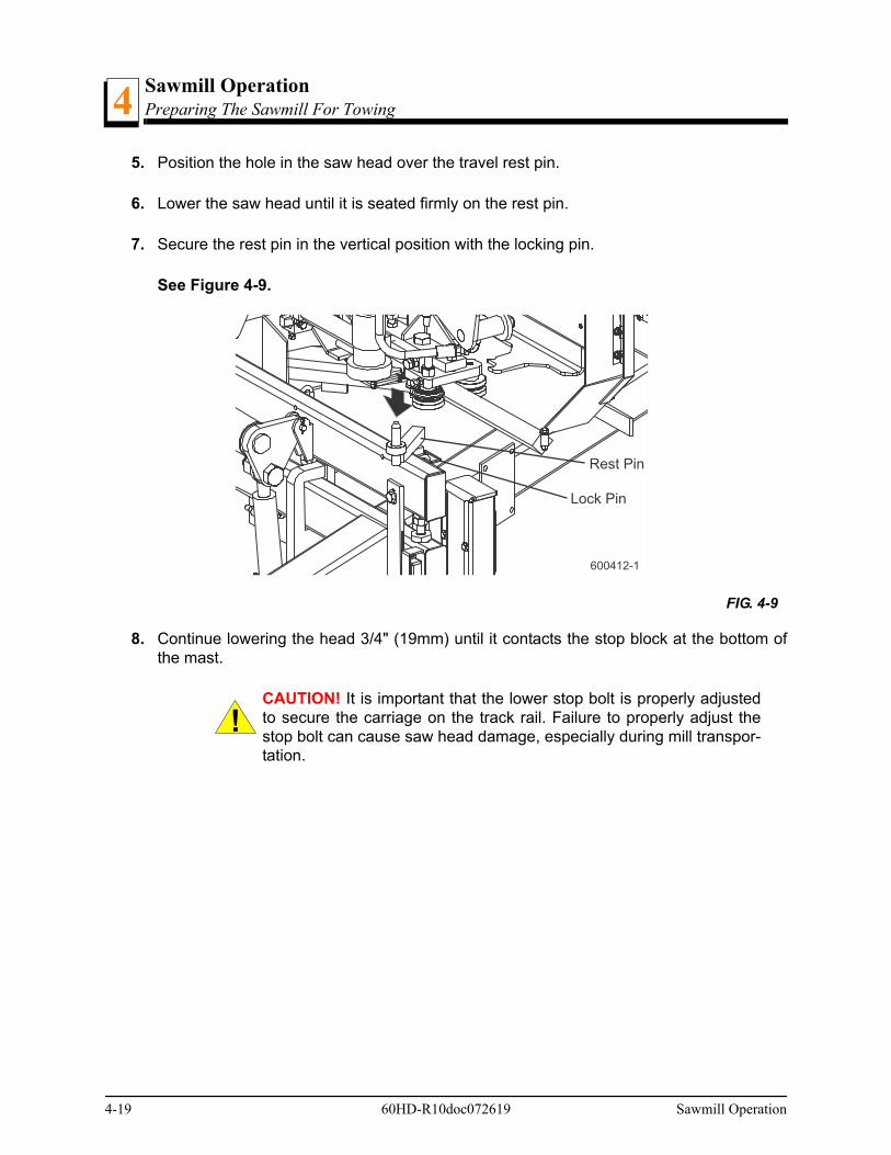
Sawmill OperationPreparing The Sawmill For Towing4
5. Position the hole in the saw head over the travel rest pin.
6. Lower the saw head until it is seated firmly on the rest pin.
7. Secure the rest pin in the vertical position with the locking pin.
See Figure 4-9.
8. Continue lowering the head 3/4" (19mm) until it contacts the stop block at the bottom ofthe mast.
CAUTION! It is important that the lower stop bolt is properly adjustedto secure the carriage on the track rail. Failure to properly adjust thestop bolt can cause saw head damage, especially during mill transpor-tation.
FIG. 4-9
600412-1
Rest Pin
Lock Pin
4-19 60HD-R10doc072619 Sawmill Operation

Sawmill OperationPreparing The Sawmill For Towing 4
9. If necessary, adjust the stop located at the bottom of the mast so the saw head contactsthe stop after it is lowered 3/4" (19mm) past where it contacts the rest pin.
See Figure 4-10.
10. Engage the autoclutch blade switch. This keeps the drive belt tight and the motor frombouncing while traveling. Be sure to disengage the autoclutch blade switch after reachingthe destination to avoid deformation of the drive belt.
11. Disconnect the cables from the back of the control box. Lay the cables in the cable stor-age box and close the lid.
12. Loosen the locking handles holding the control box to the stand. Lift the control box fromthe stand and place on the storage bracket on the sawmill frame. Tighten the locking han-dles. Insert the stand in the second outrigger tube (just in front of the first bed rail). Securethe pivot bed rail with the rubber strap to prevent it from hitting the control box duringtravel.
13. Place the chain support bracket under the cable chain, located between the first and sec-ond bed rails.
FIG. 4-10
600011-6
Loosen jam nut andturn bolt to raise orlower stop bolt
Sawmill Operation 60HD-R10doc072619 4-20

Sawmill OperationPreparing The Sawmill For Towing4
See Figure 4-11.
14. Tighten the support handles and secure the chain to the support with the rubber strap.
15. Hook the carriage safety chain located at the bottom of the carriage to the bracket at thebottom of the mast.
FIG. 4-11
Install chain supportto top track rail between first and second bed rails
Clamp support torail with handles
3H0480
Secure chain tosupport with strap
4-21 60HD-R10doc072619 Sawmill Operation
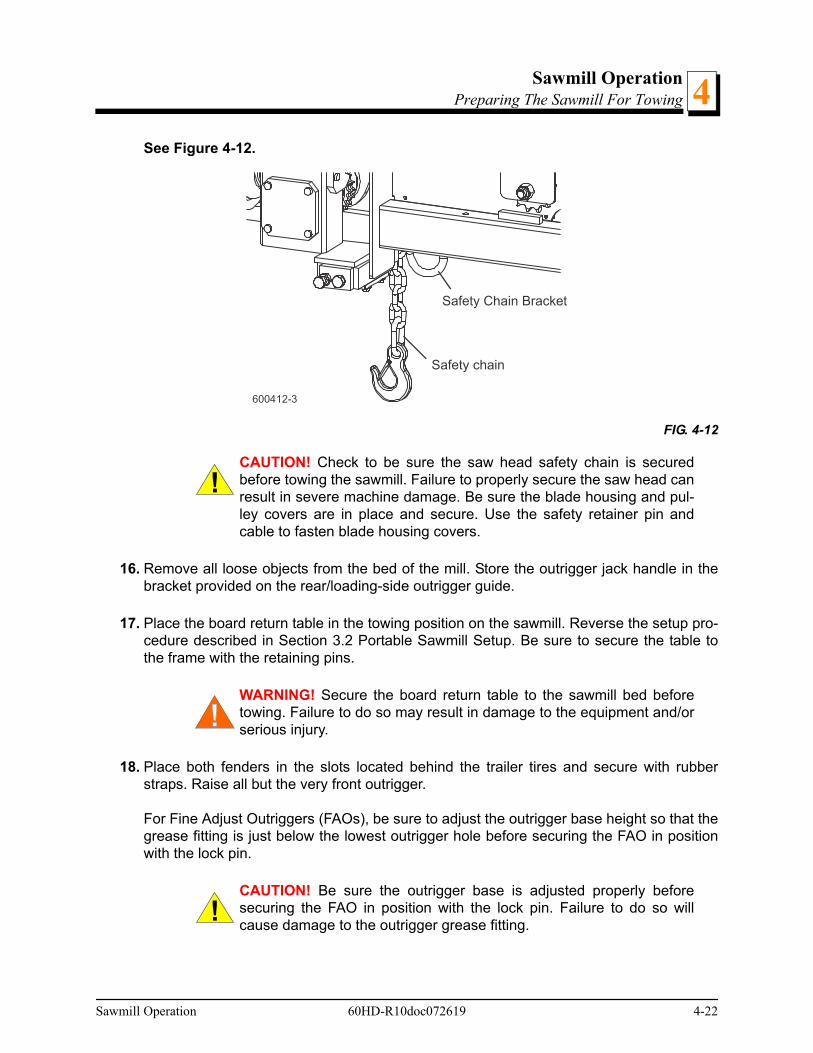
Sawmill OperationPreparing The Sawmill For Towing 4
See Figure 4-12.
CAUTION! Check to be sure the saw head safety chain is securedbefore towing the sawmill. Failure to properly secure the saw head canresult in severe machine damage. Be sure the blade housing and pul-ley covers are in place and secure. Use the safety retainer pin andcable to fasten blade housing covers.
16. Remove all loose objects from the bed of the mill. Store the outrigger jack handle in thebracket provided on the rear/loading-side outrigger guide.
17. Place the board return table in the towing position on the sawmill. Reverse the setup pro-cedure described in Section 3.2 Portable Sawmill Setup. Be sure to secure the table tothe frame with the retaining pins.
WARNING! Secure the board return table to the sawmill bed beforetowing. Failure to do so may result in damage to the equipment and/orserious injury.
18. Place both fenders in the slots located behind the trailer tires and secure with rubberstraps. Raise all but the very front outrigger.
For Fine Adjust Outriggers (FAOs), be sure to adjust the outrigger base height so that thegrease fitting is just below the lowest outrigger hole before securing the FAO in positionwith the lock pin.
CAUTION! Be sure the outrigger base is adjusted properly beforesecuring the FAO in position with the lock pin. Failure to do so willcause damage to the outrigger grease fitting.
FIG. 4-12
600412-3
Safety Chain Bracket
Safety chain
Sawmill Operation 60HD-R10doc072619 4-22

Sawmill OperationPreparing The Sawmill For Towing4
CAUTION! Do not adjust the FAO outrigger base height while there isweight on the FAO. Damage to the FAO may result.
See the trailer operator’s manual for specific information regarding hitch operation andtowing the sawmill.
4-23 60HD-R10doc072619 Sawmill Operation
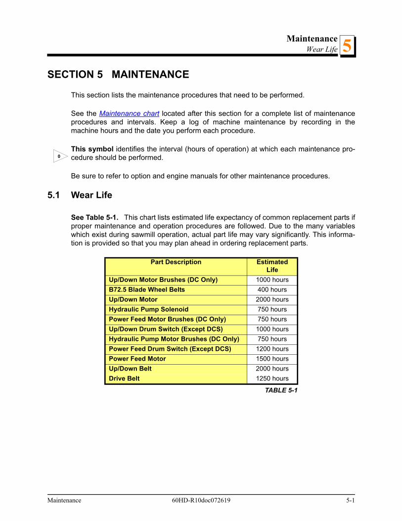
MaintenanceWear Life
Maintenance 60HD-R10doc072619 5-1
5
SECTION 5 MAINTENANCE
This section lists the maintenance procedures that need to be performed.
See the Maintenance chart located after this section for a complete list of maintenanceprocedures and intervals. Keep a log of machine maintenance by recording in themachine hours and the date you perform each procedure.
This symbol identifies the interval (hours of operation) at which each maintenance pro-cedure should be performed.
Be sure to refer to option and engine manuals for other maintenance procedures.
5.1 Wear Life
See Table 5-1. This chart lists estimated life expectancy of common replacement parts ifproper maintenance and operation procedures are followed. Due to the many variableswhich exist during sawmill operation, actual part life may vary significantly. This informa-tion is provided so that you may plan ahead in ordering replacement parts.
Part Description Estimated Life
Up/Down Motor Brushes (DC Only) 1000 hours
B72.5 Blade Wheel Belts 400 hours
Up/Down Motor 2000 hours
Hydraulic Pump Solenoid 750 hours
Power Feed Motor Brushes (DC Only) 750 hours
Up/Down Drum Switch (Except DCS) 1000 hours
Hydraulic Pump Motor Brushes (DC Only) 750 hours
Power Feed Drum Switch (Except DCS) 1200 hours
Power Feed Motor 1500 hours
Up/Down Belt 2000 hours
Drive Belt 1250 hours
TABLE 5-1
0

MaintenanceBlade Guides5
5.2 Blade Guides
WARNING! Before performing service near moving parts such asblades, pulleys, motors, belts and chains, first turn the key switch tothe OFF (#0) position and remove the key. If the key is turned on andmoving parts activated, serious injury may result.
1. Check the rollers for performance and wear every blade change. Make sure the rollersare clean and spinning freely. If not, replace them. Replace any rollers which have wornsmooth or have become cone shaped.
2. Inspect the blocks at every blade change for damage or wear. If the block housing is bentor damaged, replace the block assembly. Also, replace the block assemblies before theblocks are worn to a point the blade may contact the lower step or housing.
3. Check the guide blocks are properly spaced from the blade every 25 hours of operation.Use the provided shim or a feeler gauge to check the blocks are adjusted .008” - .010”from the blade.
4. As the blocks wear, the front inside corner will wear more than the body of the block.When the corner wears far enough, sawing performance will be affected even if the bodyof the block is adjusted properly to the blade. At this point, the block should be replaced.If you have access to the appropriate equipment, you can grind or mill the blocks to a newflat surface and reuse them. It is recommended you develop a routine schedule forreplacing the blade guide blocks based on your sawing conditions and experience.
To adjust the top block down, loosen the clamp bolt and mounting bolt. Turn the adjust-ment bolt clockwise. Retighten the mounting bolt and clamp bolt.
To adjust the bottom block up, loosen the clamp bolt and mounting bolt. Use the providedadjustment tool to turn the adjustment screw clockwise. Retighten the mounting bolt andclamp bolt.
IMPORTANT! The blocks should be parallel to the blade. See Section7.2 for instructions about checking and adjusting the assembly levelwith the blade.
25
5-2 60HD-R10doc072619 Maintenance
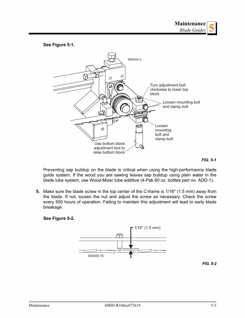
MaintenanceBlade Guides 5
See Figure 5-1.
Preventing sap buildup on the blade is critical when using the high-performance bladeguide system. If the wood you are sawing leaves sap buildup using plain water in theblade lube system, use Wood-Mizer lube additive (4-Pak 60 oz. bottles part no. ADD-1).
5. Make sure the blade screw in the top center of the C-frame is 1/16" (1.5 mm) away fromthe blade. If not, loosen the nut and adjust the screw as necessary. Check the screwevery 500 hours of operation. Failing to maintain this adjustment will lead to early bladebreakage.
See Figure 5-2.
FIG. 5-1
FIG. 5-2
600244-3
Turn adjustment boltclockwise to lower topblock
Loosen mounting boltand clamp bolt
Use bottom blockadjustment tool toraise bottom block
Loosenmountingbolt andclamp bolt
1/16” (1.5 mm)
600005-15
Maintenance 60HD-R10doc072619 5-3
MaintenanceSawdust Removal5
5-4 60HD-R10doc072619 Maintenance
5.3 Sawdust Removal
WARNING! Before performing service near moving parts such asblades, pulleys, motors, belts and chains, first turn the key switch tothe OFF (#0) position and remove the key. If the key is turned on andmoving parts activated, serious injury may result.
Remove the excess sawdust from the blade wheel housings and sawdust chute everyblade change.
WARNING! Always keep clear of exiting sawdust. Keep hands, feetand any other objects away from the sawdust chute when operatingsawmill. Failure to do so may result in serious injury.
WARNING! Always check to ensure the steel fingers inside the saw-dust chute are in place before operating the sawmill. The steel fingershave been designed to help prevent a broken blade or some otherobject from becoming a projectile and exiting the sawdust chute. Fail-ure to have these fingers in place may result in serious injury.
Remove all sawdust and debris from around the velocity fuse valves every 8 hours ofoperation. The valves are located at the bottom of the log loader cylinders.
Remove sawdust buildup as necessary from the battery box lid and top rail cover.
CAUTION! Failure to remove sawdust buildup from the battery box lidand/or track rail cover could result in damage to these parts when thesaw head is lowered to its lowest position.
Remove sawdust and debris from grounding block along the bed rail and mast.
AR
8
50

MaintenanceCarriage Track, Wiper & Scraper 5
5.4 Carriage Track, Wiper & Scraper
WARNING! Before performing service near moving parts such asblades, pulleys, motors, belts and chains, first turn the key switch tothe OFF (#0) position and remove the key. If the key is turned on andmoving parts activated, serious injury may result.
Properly maintaining the sawmill carriage track is critical in preventing corrosion that cancause pitting and scaling on the rail surfaces. Pitted and scaled surfaces can, in turn,cause rough cuts or jerky power feed movement.
1. Clean track rails to remove any sawdust and sap buildup every eight hours of operation.
Use a light-grade sandpaper or emery cloth to sand off any rust or other adhering parti-cles from the rails.
CAUTION! Keep track rails free of rust. Formation of rust on the trackrail in the areas where the cam bearings roll can cause rapid deteriora-tion of the track rail's surface.
Lubricate the rails by wiping them with Dexron III ATF transmission fluid. Lubrication willhelp protect the rails from corrosive elements such as acid rain and/or moisture fromnearby bodies of saltwater (if applicable). This lubrication is essential to maintain theintegrity of the track rails and track rollers and to achieve long service life.
2. Remove sawdust from the track roller housings and lubricate the felt track wiper everytwenty-five hours of operation.
Remove the track roller housing covers and brush any sawdust buildup from the hous-ings.
Clean and lubricate the felt track wipers. Unbolt the middle track cover, remove from thesawmill and remove any sawdust buildup. Soak the felt wiper with Dexron III transmissionfluid.
CAUTION! Reinstall the track wiper so that it lightly touches the trackrail. If the wiper presses too firmly against the rail, it can cause thepower feed to bind.
8
25
Maintenance 60HD-R10doc072619 5-5

MaintenanceCarriage Track, Wiper & Scraper5
3. Check the track scrapers as needed. Make sure the scrapers fit firmly against the rail. If atrack scraper needs to be adjusted, loosen the screw, push the scraper downward until itfits firmly against the rail, and retighten the screw.
See Figure 5-3.
FIG. 5-3
AR
600011C
Clean sawdustfrom track rollerhousings
Clean andlubricatetrack wiper
Adjust trackscrapers
TrackRail
5-6 60HD-R10doc072619 Maintenance

MaintenanceVertical Mast Rails
Maintenance 60HD-R10doc072619 5-7
55.5 Vertical Mast Rails
WARNING! Before performing service near moving parts such asblades, pulleys, motors, belts and chains, first turn the key switch tothe OFF (#0) position and remove the key. If the key is turned on andmoving parts activated, serious injury may result.
Clean the vertical mast rails every 50 hours of operation. Clean with solvent and removeany rust with a light-grade sand paper or emery cloth.
CAUTION! Never use grease on the mast rails as it will collect saw-dust.
50

MaintenanceDrum Switches5
5-8 60HD-R10doc072619 Maintenance
5.6 Drum Switches
WARNING! Disconnect and lockout power before performing any ser-vice to the electrical system. For battery-powered equipment, discon-nect the negative battery terminal cable. For AC-powered equipment,follow the lockout procedure provided in the safety section (See Sec-tion 2.2). Failure to do so may result in injury and/or electrical systemdamage.
Lubricate the up/down and power feed drum switch contacts inside the control panelevery fifty hours of operation. Use only contact grease supplied by Wood-Mizer. Removethe control panel cover. Use a cotton swab to apply grease to the switch contact ends.
WARNING! Drum switch grease contains Petroleum HydrocarbonLubricant. Eye and skin irritant. If introduced into eyes, flush with waterfor at least 15 minutes. If film or irritation persists, seek medical atten-tion. Wash skin with soap and water. If ingested, do not induce vomit-ing - contact a physician. KEEP OUT OF THE REACH OF CHILDREN.
50

MaintenanceMiscellaneous
Maintenance 60HD-R10doc072619 5-9
55.7 Miscellaneous
WARNING! Before performing service near moving parts such asblades, pulleys, motors, belts and chains, first turn the key switch tothe OFF (#0) position and remove the key. If the key is turned on andmoving parts activated, serious injury may result.
1. Oil all chains with Dexron III ATF every fifty hours of operation.
CAUTION! Do not use chain lube. It causes sawdust buildup in chainlinks.
2. Apply a thin film of a NLGI No. 2 grade lithium grease to the blade guide arm every fiftyhours of operation to help prevent it from rusting.
3. Adjust the blade guide arm drive chain as necessary to prevent the arm from slipping. Toadjust the chain, loosen the blade guide arm motor mounting plate bolts and slide themotor to take slack out of the chain.
4. Apply NLGI No. 2 grade lithium grease to the drive belt tensioner pivot every fifty hours ofoperation.
See Figure 5-4.
5. Grease the clamp mechanism, loading arm and side support pivots with a NLGI No. 2grade lithium grease every fifty hours of operation.
6. Check the mill alignment every setup (See Section SECTION 7).
7. Make sure all safety warning decals are readable. Remove sawdust and dirt. Replace anydamaged or unreadable decals immediately. Order decals from your Customer ServiceRepresentative.
FIG. 5-4
50
50
AR
50
600005-20B
GreaseFitting
50
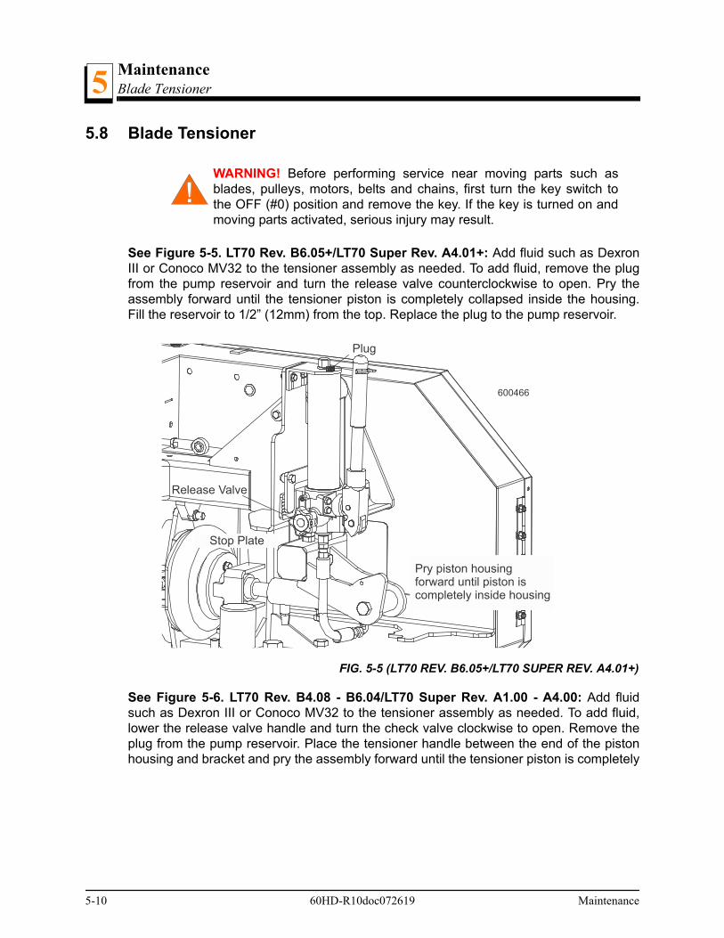
MaintenanceBlade Tensioner5
5.8 Blade Tensioner
WARNING! Before performing service near moving parts such asblades, pulleys, motors, belts and chains, first turn the key switch tothe OFF (#0) position and remove the key. If the key is turned on andmoving parts activated, serious injury may result.
See Figure 5-5. LT70 Rev. B6.05+/LT70 Super Rev. A4.01+: Add fluid such as DexronIII or Conoco MV32 to the tensioner assembly as needed. To add fluid, remove the plugfrom the pump reservoir and turn the release valve counterclockwise to open. Pry theassembly forward until the tensioner piston is completely collapsed inside the housing.Fill the reservoir to 1/2” (12mm) from the top. Replace the plug to the pump reservoir.
See Figure 5-6. LT70 Rev. B4.08 - B6.04/LT70 Super Rev. A1.00 - A4.00: Add fluidsuch as Dexron III or Conoco MV32 to the tensioner assembly as needed. To add fluid,lower the release valve handle and turn the check valve clockwise to open. Remove theplug from the pump reservoir. Place the tensioner handle between the end of the pistonhousing and bracket and pry the assembly forward until the tensioner piston is completely
FIG. 5-5 (LT70 REV. B6.05+/LT70 SUPER REV. A4.01+)
600466
Plug
Release Valve
Stop Plate
Pry piston housingforward until piston iscompletely inside housing
5-10 60HD-R10doc072619 Maintenance
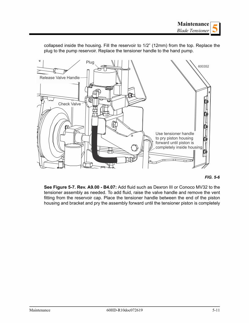
MaintenanceBlade Tensioner 5
collapsed inside the housing. Fill the reservoir to 1/2” (12mm) from the top. Replace theplug to the pump reservoir. Replace the tensioner handle to the hand pump.
See Figure 5-7. Rev. A9.00 - B4.07: Add fluid such as Dexron III or Conoco MV32 to thetensioner assembly as needed. To add fluid, raise the valve handle and remove the ventfitting from the reservoir cap. Place the tensioner handle between the end of the pistonhousing and bracket and pry the assembly forward until the tensioner piston is completely
FIG. 5-6
600352
Release Valve Handle
Plug
Check Valve
Use tensioner handleto pry piston housingforward until piston iscompletely inside housing
Maintenance 60HD-R10doc072619 5-11

MaintenanceBlade Tensioner5
collapsed inside the housing. Fill the reservoir to 1/4” (12mm) from the top. Replace thevent fitting.
8. Lubricate the tensioner screw handle with a NLGI No. 2 grade lithium grease as needed.
9.
FIG. 5-7 REV. A9.00 - B4.07
600239-8
Remove ventfitting
Fill reservoir withhydraulic fluid
Use tensioner handleto pry piston housingforward until piston iscompletely inside housing
Raise valvehandle
5-12 60HD-R10doc072619 Maintenance

MaintenanceBlade Wheel Belts
Maintenance 60HD-R10doc072619 5-13
55.9 Blade Wheel Belts
WARNING! Before performing service near moving parts such asblades, pulleys, motors, belts and chains, first turn the key switch tothe OFF (#0) position and remove the key. If the key is turned on andmoving parts activated, serious injury may result.
Rotate the blade wheel belts and check them for wear. Rotating the belts every 50 hourswill provide longer belt life. Replace belts as necessary. Use only B72.5 belts supplied byWood-Mizer.
50

MaintenanceDrive Belt Adjustment5
5.10 Drive Belt Adjustment
WARNING! Disconnect and lockout power before performing any ser-vice to the electrical system. For battery-powered equipment, discon-nect the negative battery terminal cable. For AC-powered equipment,follow the lockout procedure provided in the safety section (See Sec-tion 2.3).Failure to do so may result in injury and/or electrical systemdamage.
WARNING! Before performing service near moving parts such asblades, pulleys, motors, belts and chains, first turn the key switch tothe OFF (#0) position and remove the key. If the key is turned on andmoving parts activated, serious injury may result.
WARNING! Do not adjust the engine drive belts or belt support bracketwith the engine running. Doing so may result in serious injury.
.CAUTION! Do not over-tighten the drive belt. Damage to the enginemay result
See Table 5-2. See the table below for drive belt tension specifications for your modelsawmill. Measure the belt tension with a gauge. NOTE: Wood-Mizer offers a belt tensiongauge (Part No. 016309) that will let you accurately measure the belt tension.
See Figure 5-8.
New Belt Installation/New Sawmill Operation Subsequent Adjustment
Engine/Motor
DeflectionInches (mm)
Installation Force
lbs. (kg)
Check After First
Acceptable Force
lbs. (kg)
Then Check Every
DeflectionInches (mm)
Forcelbs. (kg)
ALL 3/8” (9.5mm) 14 lbs. (6.35kg) 20 hrs 14 lbs. (6.35kg) 50 hrs 3/8” (9.5mm) 14 lbs. (6.35kg)
TABLE 5-2
FIG. 5-8
50
3/8" (9.5mm)
600224 Jam Nut
Adjustment Tube
5-14 60HD-R10doc072619 Maintenance
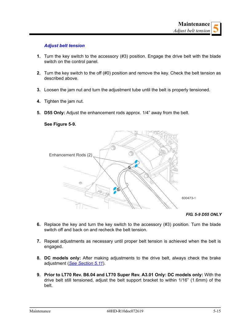
MaintenanceAdjust belt tension 5
Adjust belt tension
1. Turn the key switch to the accessory (#3) position. Engage the drive belt with the bladeswitch on the control panel.
2. Turn the key switch to the off (#0) position and remove the key. Check the belt tension asdescribed above.
3. Loosen the jam nut and turn the adjustment tube until the belt is properly tensioned.
4. Tighten the jam nut.
5. D55 Only: Adjust the enhancement rods approx. 1/4” away from the belt.
See Figure 5-9.
6. Replace the key and turn the key switch to the accessory (#3) position. Turn the bladeswitch off and back on and recheck the belt tension.
7. Repeat adjustments as necessary until proper belt tension is achieved when the belt isengaged.
8. DC models only: After making adjustments to the drive belt, always check the brakeadjustment (See Section 5.11).
9. Prior to LT70 Rev. B6.04 and LT70 Super Rev. A3.01 Only: DC models only: With thedrive belt still tensioned, adjust the belt support bracket to within 1/16” (1.6mm) of thebelt.
FIG. 5-9 D55 ONLY
600473-1
Enhancement Rods (2)
Maintenance 60HD-R10doc072619 5-15
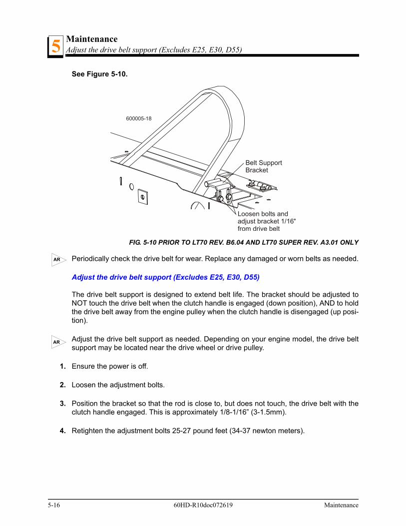
MaintenanceAdjust the drive belt support (Excludes E25, E30, D55)5
See Figure 5-10.
Periodically check the drive belt for wear. Replace any damaged or worn belts as needed.
Adjust the drive belt support (Excludes E25, E30, D55)
The drive belt support is designed to extend belt life. The bracket should be adjusted toNOT touch the drive belt when the clutch handle is engaged (down position), AND to holdthe drive belt away from the engine pulley when the clutch handle is disengaged (up posi-tion).
Adjust the drive belt support as needed. Depending on your engine model, the drive beltsupport may be located near the drive wheel or drive pulley.
1. Ensure the power is off.
2. Loosen the adjustment bolts.
3. Position the bracket so that the rod is close to, but does not touch, the drive belt with theclutch handle engaged. This is approximately 1/8-1/16” (3-1.5mm).
4. Retighten the adjustment bolts 25-27 pound feet (34-37 newton meters).
FIG. 5-10 PRIOR TO LT70 REV. B6.04 AND LT70 SUPER REV. A3.01 ONLY
Belt SupportBracket
Loosen bolts andadjust bracket 1/16"from drive belt
600005-18
AR
AR
5-16 60HD-R10doc072619 Maintenance

MaintenanceBrake Adjustment (DC Only)
Maintenance 60HD-R10doc072619 5-17
55.11 Brake Adjustment (DC Only)
WARNING! Before performing service near moving parts such asblades, pulleys, motors, belts and chains, first turn the key switch tothe OFF (#0) position and remove the key. If the key is turned on andmoving parts activated, serious injury may result.
Check the brake pads for wear every 200 hours of operation. Replace if damaged orworn.
Also check and adjust the brake pads after each drive belt adjustment or if the blade doesnot stop quickly. Adjust the brake pads if the drive belt jumps from the drive pulley whenthe autoclutch is disengaged.
See Figure 5-11. The brake should be adjusted so the blade stops no more than 7 sec-onds after turning the blade switch off. Loosen the jam nuts around the adjustment turn-buckle and turn the turnbuckle to adjust the brake. Retighten the jam nuts.Multiple adjustments of the brake will affect engine RPM at idle. If you notice any changein the idle of the engine after adjusting the brake, check the RPM and adjust the throttlecable if necessary to allow the throttle plate to rest on the idle stop screw (See Enginemanual).
FIG. 5-11
200
600005-17B
Brake AdjustmentTurnbuckle
BrakePads
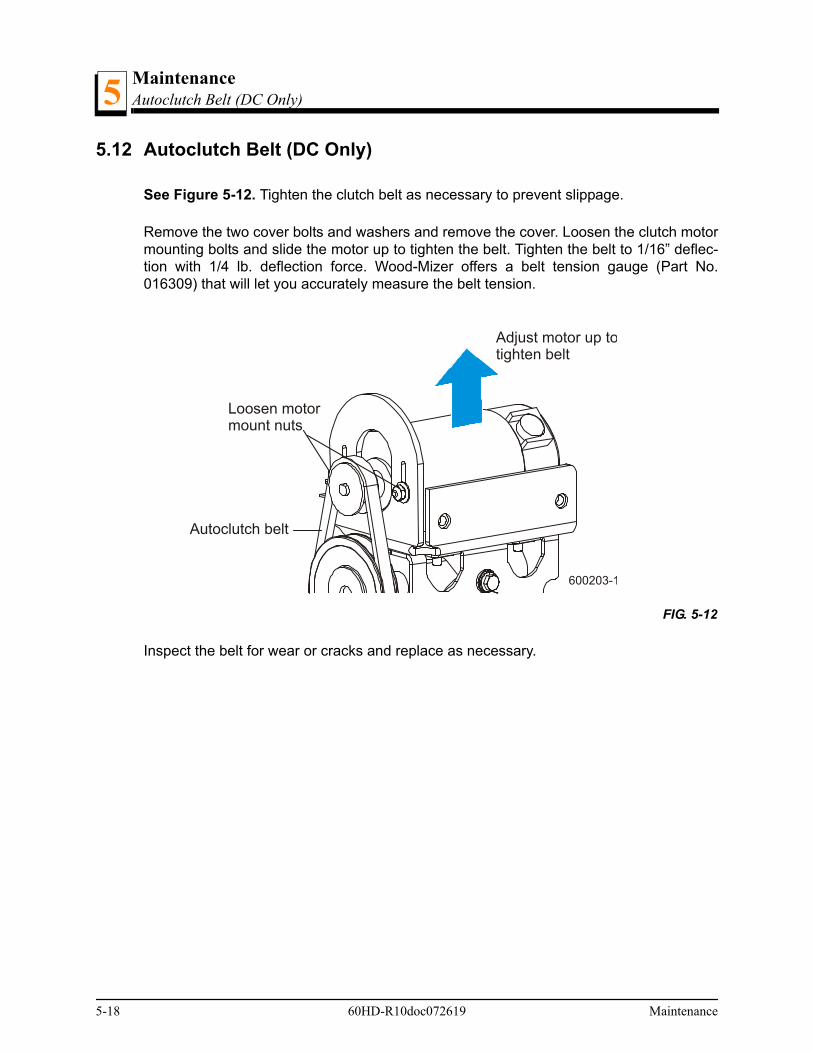
MaintenanceAutoclutch Belt (DC Only)5
5-18 60HD-R10doc072619 Maintenance
5.12 Autoclutch Belt (DC Only)
See Figure 5-12. Tighten the clutch belt as necessary to prevent slippage.
Remove the two cover bolts and washers and remove the cover. Loosen the clutch motormounting bolts and slide the motor up to tighten the belt. Tighten the belt to 1/16” deflec-tion with 1/4 lb. deflection force. Wood-Mizer offers a belt tension gauge (Part No.016309) that will let you accurately measure the belt tension.
Inspect the belt for wear or cracks and replace as necessary.
FIG. 5-12
Loosen motormount nuts
Adjust motor up totighten belt
Autoclutch belt
600203-1
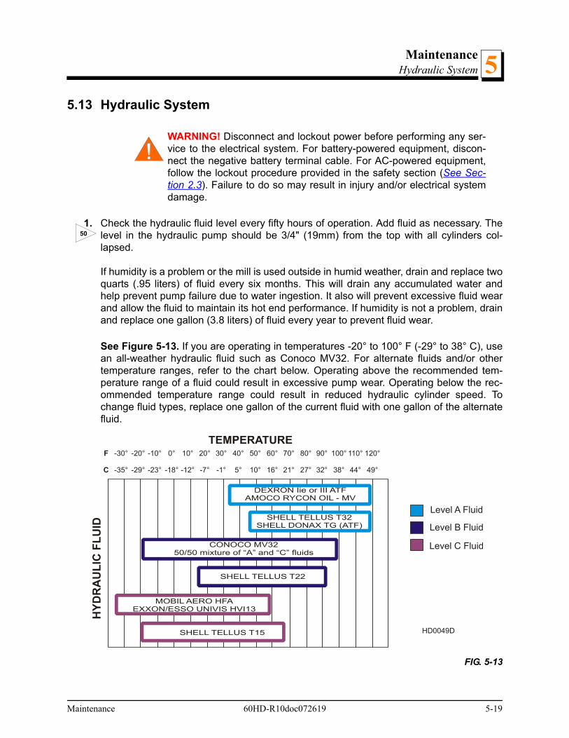
MaintenanceHydraulic System 5
5.13 Hydraulic System
WARNING! Disconnect and lockout power before performing any ser-vice to the electrical system. For battery-powered equipment, discon-nect the negative battery terminal cable. For AC-powered equipment,follow the lockout procedure provided in the safety section (See Sec-tion 2.3). Failure to do so may result in injury and/or electrical systemdamage.
1. Check the hydraulic fluid level every fifty hours of operation. Add fluid as necessary. Thelevel in the hydraulic pump should be 3/4" (19mm) from the top with all cylinders col-lapsed.
If humidity is a problem or the mill is used outside in humid weather, drain and replace twoquarts (.95 liters) of fluid every six months. This will drain any accumulated water andhelp prevent pump failure due to water ingestion. It also will prevent excessive fluid wearand allow the fluid to maintain its hot end performance. If humidity is not a problem, drainand replace one gallon (3.8 liters) of fluid every year to prevent fluid wear.
See Figure 5-13. If you are operating in temperatures -20° to 100° F (-29° to 38° C), usean all-weather hydraulic fluid such as Conoco MV32. For alternate fluids and/or othertemperature ranges, refer to the chart below. Operating above the recommended tem-perature range of a fluid could result in excessive pump wear. Operating below the rec-ommended temperature range could result in reduced hydraulic cylinder speed. Tochange fluid types, replace one gallon of the current fluid with one gallon of the alternatefluid.
FIG. 5-13
50
HD0049D
120°
49°
40°
5°
80°
27°
0°
-18°
100°
38°
20°
-7°
60°
16°
-20°
-29°
110°
44°
30°
-1°
70°
21°
-10°
-23°
90°
32°
10°
-12°
50°
10°
-30°
-35°
F
C
Level A Fluid
Level B Fluid
Level C Fluid
HY
DR
AU
LIC
FL
UID
TEMPERATURE
Maintenance 60HD-R10doc072619 5-19

MaintenanceHydraulic System5
2. Replace the hydraulic system cartridge filter every 500 hours of operation.
3. DC Only: Inspect the hydraulic pump motor brushes every 750 hours of operation.Remove brush dust and replace the brushes if they worn to a length of 1/4” (6mm) orshorter.
CAUTION! Do not operate the hydraulic system if the pump motorbrushes are worn shorter than 1/4” (6mm). Damage to the pump motormay result.
4. Periodically check all hydraulic lines and fitting as needed. Replace as necessary.
500
750
5-20 60HD-R10doc072619 Maintenance

MaintenanceUp/Down System 5
5.14 Up/Down System
WARNING! Before performing service near moving parts such asblades, pulleys, motors, belts and chains, first turn the key switch tothe OFF (#0) position and remove the key. If the key is turned on andmoving parts activated, serious injury may result.
WARNING! Disconnect and lockout power before performing any ser-vice to the electrical system. For battery-powered equipment, discon-nect the negative battery terminal cable. For AC-powered equipment,follow the lockout procedure provided in the safety section (See Sec-tion 2.3). Failure to do so may result in injury and/or electrical systemdamage.
Adjust the up/down chain tension as needed. Measure chain tension with the head all theway to the top of the vertical mast. Secure the head with a chain at the top. Find the chainadjusting bolt at the bottom of the mast. Use the adjustment nut to adjust the bolt until thecenter of the chain can be deflected 3/4” (1.9cm) forward with a 5 lb. (2.3 Kg) deflectionforce.
WARNING! Always secure the saw head with a 5/16" chain with atleast 1900 lbs. working load capacity before adjusting the up/downchain. The cutting head may fall, causing severe injury or death.
CAUTION! Do not over-tension the chain. Over-tensioning the chainmay lead to early failure of the gear reducer.
See Figure 5-14.
FIG. 5-14
AR
AdjustmentNut600016
Maintenance 60HD-R10doc072619 5-21

MaintenanceUp/Down System5
5. The up/down motor features a spring-loaded belt design. Belt tension is automaticallymaintained and requires no adjustment. Replace the belt when adequate belt tension canno longer be obtained.
WARNING! Always secure the saw head with a 5/16" chain with atleast 1900 lbs. working load capacity before removing the up/downmotor belt. The cutting head may fall, causing severe injury or death.
Periodically check the belt for wear. Replace any damaged or worn belts as needed.
6. Check the up/down gearbox oil level. Add a synthetic gear oil such as Mobil Glygoyle 460as needed.
Drain and refill the gearbox with 40 (1.2L) ounces of oil after every 5000 hours of sawmilloperation or every year, whichever comes first.
Wood-Mizer offers replacement gear oil in 8 ounce (0.24L) bottles.
7. Inspect the up/down motor brushes every 750 hours of operation. Remove brush dustand replace the brushes if they worn to a length of 5/8” (16mm) or shorter.
CAUTION! Do not operate the up/down system if the motor brushesare worn shorter than 5/8” (16mm). Damage to the up/down motor mayresult.
The up/down system is equipped with a gas spring assist mechanism to provide improvedspeed and performance. The saw head must be secured and tension released from theassist assembly before performing any maintenance to assist components.
WARNING! Always secure the saw head with a 5/16" (8mm) chainwith at least 1900 lbs. (860Kg) working load capacity before servicingthe up/down assist. The cutting head may fall, causing severe injury ordeath.
WARNING! Release pressure from the up/down assist prior to per-forming any service to the assembly. Failure to do so may result in theassembly flying apart, causing injury or damage to the equipment.
AR
750
AR
8
5-22 60HD-R10doc072619 Maintenance

MaintenanceUp/Down System 5
1. Locate the four upper up/down assist mounting bolts. Remove the two lower set ofmounting bolts.
See Table 5-3.
2. Raise the saw head all the way to the top of the mast and secure with a chain.
3. Locate the up/down assist tension assembly.
FIG. 5-14
600188-2
Remove bottomtwo upper mountngbolts
Maintenance 60HD-R10doc072619 5-23

MaintenanceUp/Down System5
See Figure 5-15.
4. Loosen (do NOT remove) the four lower mounting bolts to allow the bracket to movealong the slotted mounting holes.
5. Turn the tension bolt counterclockwise to remove tension from the up/down system. Turnthe bolt until it disengages from the mounting plate assembly.
6. Remove the four lower mounting bolts and lift the mounting plate to access the up/downchain. Disassemble the master link securing the chain to the saw head.
FIG. 5-15
600188B
Loosen Lower Mounting Bolts (4)
Turn Tension BoltCounterclockwise toRemove Tension
5-24 60HD-R10doc072619 Maintenance
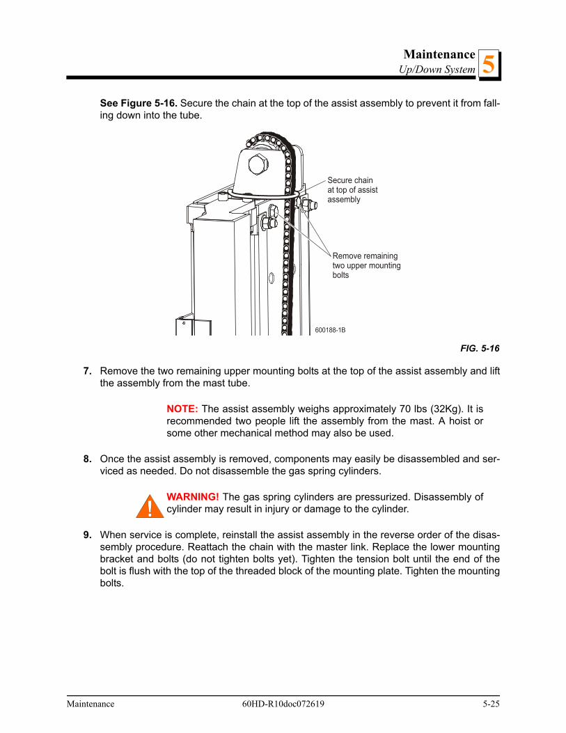
MaintenanceUp/Down System 5
See Figure 5-16. Secure the chain at the top of the assist assembly to prevent it from fall-ing down into the tube.
7. Remove the two remaining upper mounting bolts at the top of the assist assembly and liftthe assembly from the mast tube.
NOTE: The assist assembly weighs approximately 70 lbs (32Kg). It isrecommended two people lift the assembly from the mast. A hoist orsome other mechanical method may also be used.
8. Once the assist assembly is removed, components may easily be disassembled and ser-viced as needed. Do not disassemble the gas spring cylinders.
WARNING! The gas spring cylinders are pressurized. Disassembly ofcylinder may result in injury or damage to the cylinder.
9. When service is complete, reinstall the assist assembly in the reverse order of the disas-sembly procedure. Reattach the chain with the master link. Replace the lower mountingbracket and bolts (do not tighten bolts yet). Tighten the tension bolt until the end of thebolt is flush with the top of the threaded block of the mounting plate. Tighten the mountingbolts.
FIG. 5-16
Secure chainat top of assistassembly
Remove remainingtwo upper mountingbolts
Maintenance 60HD-R10doc072619 5-25
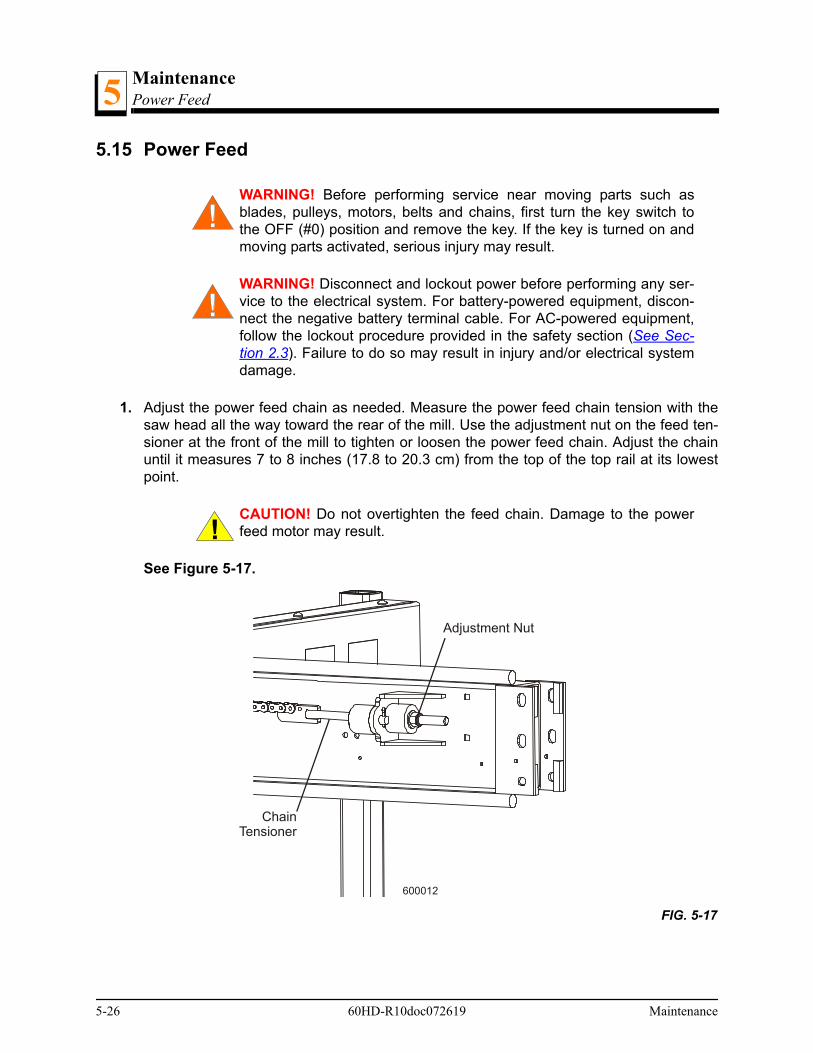
MaintenancePower Feed5
5.15 Power Feed
WARNING! Before performing service near moving parts such asblades, pulleys, motors, belts and chains, first turn the key switch tothe OFF (#0) position and remove the key. If the key is turned on andmoving parts activated, serious injury may result.
WARNING! Disconnect and lockout power before performing any ser-vice to the electrical system. For battery-powered equipment, discon-nect the negative battery terminal cable. For AC-powered equipment,follow the lockout procedure provided in the safety section (See Sec-tion 2.3). Failure to do so may result in injury and/or electrical systemdamage.
1. Adjust the power feed chain as needed. Measure the power feed chain tension with thesaw head all the way toward the rear of the mill. Use the adjustment nut on the feed ten-sioner at the front of the mill to tighten or loosen the power feed chain. Adjust the chainuntil it measures 7 to 8 inches (17.8 to 20.3 cm) from the top of the top rail at its lowestpoint.
CAUTION! Do not overtighten the feed chain. Damage to the powerfeed motor may result.
See Figure 5-17.
FIG. 5-17
Adjustment Nut
ChainTensioner
600012
5-26 60HD-R10doc072619 Maintenance
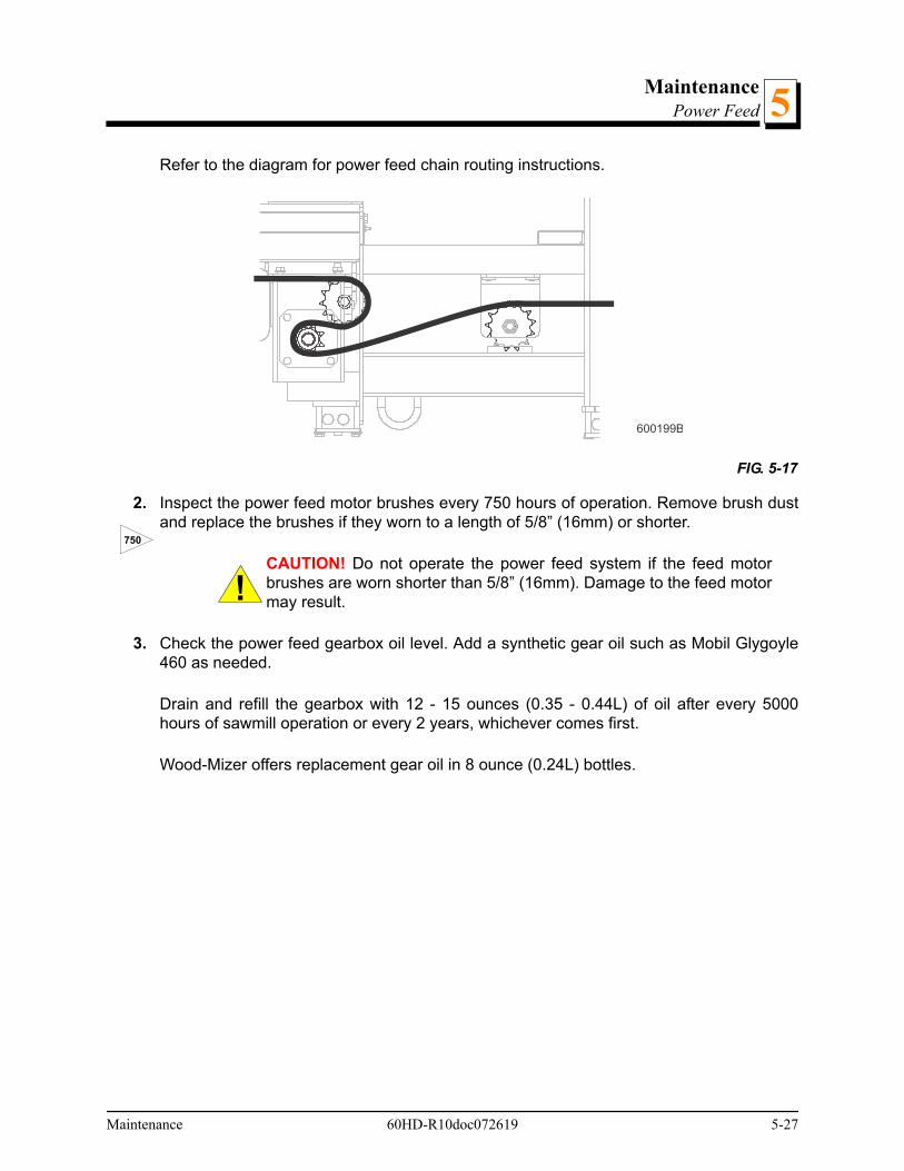
MaintenancePower Feed 5
Refer to the diagram for power feed chain routing instructions.
2. Inspect the power feed motor brushes every 750 hours of operation. Remove brush dustand replace the brushes if they worn to a length of 5/8” (16mm) or shorter.
CAUTION! Do not operate the power feed system if the feed motorbrushes are worn shorter than 5/8” (16mm). Damage to the feed motormay result.
3. Check the power feed gearbox oil level. Add a synthetic gear oil such as Mobil Glygoyle460 as needed.
Drain and refill the gearbox with 12 - 15 ounces (0.35 - 0.44L) of oil after every 5000hours of sawmill operation or every 2 years, whichever comes first.
Wood-Mizer offers replacement gear oil in 8 ounce (0.24L) bottles.
FIG. 5-17
600199B
750
Maintenance 60HD-R10doc072619 5-27
MaintenanceCharging The Battery (DC Only)5
5.16 Charging The Battery (DC Only)
DANGER! Batteries expel explosive gases. Keep sparks, flames,burning cigarettes, or other ignition sources away at all times. Alwayswear safety goggles and a face shield when working near batteries.
Failure to do so will cause serious injury.1
WARNING! Battery posts, terminals and related accessories containlead and lead compounds, chemicals known to the State of Californiato cause cancer and reproductive harm. Wash hands after handling.
WARNING! Charge the battery in a well ventilated area. Do notattempt to charge a frozen battery.
Use extreme care to avoid spilling or splashing electrolyte (which isdilute sulfuric acid) as it can destroy clothing and burn the skin.
If electrolyte is spilled or splashed on any surface of the machine, itshould be neutralized and rinsed with clean water.
CAUTION! Do not overcharge the battery. Overcharging may reducethe overall service life of the battery.
CAUTION! Be sure the battery is fully charged before transporting thesawmill. If the battery is not fully charged, excessive vibration couldreduce the overall service life of the battery.
1.Battery Council International, copyright 1987
EMERGENCY TREATMENT FOR CONTACT WITH BATTERY COMPONENTS (LEAD/SUL-FURIC ACID) per SDS (Safety Data Sheet):
EYE CONTACT Sulfuric Acid and Lead: Flush eyes immediately with large amounts of water for at least 15 minutes while lifting lids. Seek immediate medical atten-tion if eyes have been exposed directly to acid.
SKIN CONTACT Sulfuric Acid: Flush affected area(s) with large amounts of water using del-uge emergency shower, if available, shower for at least 15 minutes. Remove contaminated clothing, including shoes. If symptoms persist, seek medical attention. Wash contaminated clothing before reuse. Discard contaminated shoes.Lead: Wash immediately with soap and water.
INGESTION Sulfuric Acid: Administer large amounts of water. Do NOT induce vomiting or aspiration into the lungs may occur and can cause permanent injury or death; consult physician.
INHALATION Sulfuric Acid: Remove to fresh air immediately. If not breathing, give artificial respiration. If breathing is difficult, give oxygen. Consult a physician.Lead: Remove from exposure, gargle, wash nose and lips; consult physician.
5-28 60HD-R10doc072619 Maintenance
MaintenanceCharging The Battery (DC Only) 5
1. Raise the saw head to access the battery box.
2. Turn the key to the OFF (#0) position and remove the key.
3. Remove the two wing nuts and flat washers holding the battery box lid to the battery box.
4. Remove the battery box lid.
5. Clean the battery terminals if necessary.
6. Connect the positive charger/jumper cable directly to the positive battery terminal.
7. Connect the negative charger/jumper cable to a grounded metal surface.
8. Follow the instructions supplied with your specific battery charger.
IMPORTANT: Be careful not to overcharge the battery, especiallywhen using a high-rate or “boost” charger (40 amps or higher). Theseare intended to quickly charge a good battery that is discharged. Theyare not intended for unattended or long-term charging.
9. After the battery is completely recharged, remove the negative charger/jumper cable fromground.
10. Remove the positive charger/jumper cable from the battery.
11. Replace the battery box lid and replace the flat washers and wing nuts.
Maintenance 60HD-R10doc072619 5-29
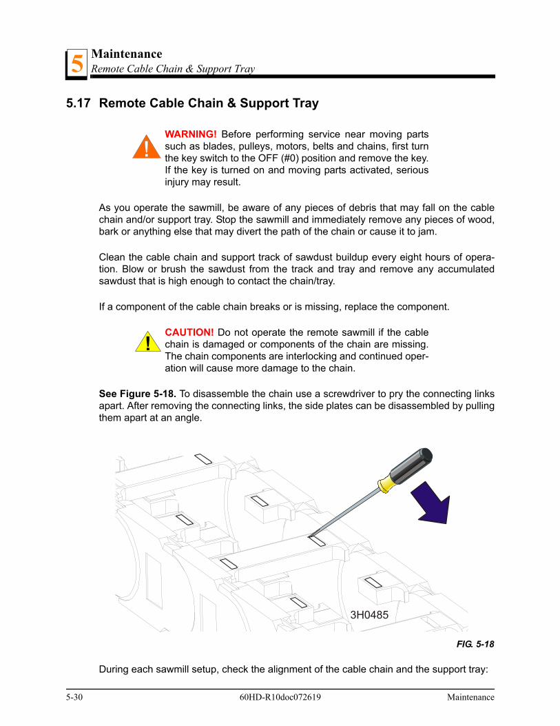
MaintenanceRemote Cable Chain & Support Tray5
5.17 Remote Cable Chain & Support Tray
WARNING! Before performing service near moving partssuch as blades, pulleys, motors, belts and chains, first turnthe key switch to the OFF (#0) position and remove the key.If the key is turned on and moving parts activated, seriousinjury may result.
As you operate the sawmill, be aware of any pieces of debris that may fall on the cablechain and/or support tray. Stop the sawmill and immediately remove any pieces of wood,bark or anything else that may divert the path of the chain or cause it to jam.
Clean the cable chain and support track of sawdust buildup every eight hours of opera-tion. Blow or brush the sawdust from the track and tray and remove any accumulatedsawdust that is high enough to contact the chain/tray.
If a component of the cable chain breaks or is missing, replace the component.
CAUTION! Do not operate the remote sawmill if the cablechain is damaged or components of the chain are missing.The chain components are interlocking and continued oper-ation will cause more damage to the chain.
See Figure 5-18. To disassemble the chain use a screwdriver to pry the connecting linksapart. After removing the connecting links, the side plates can be disassembled by pullingthem apart at an angle.
During each sawmill setup, check the alignment of the cable chain and the support tray:
FIG. 5-18
3H0485
5-30 60HD-R10doc072619 Maintenance
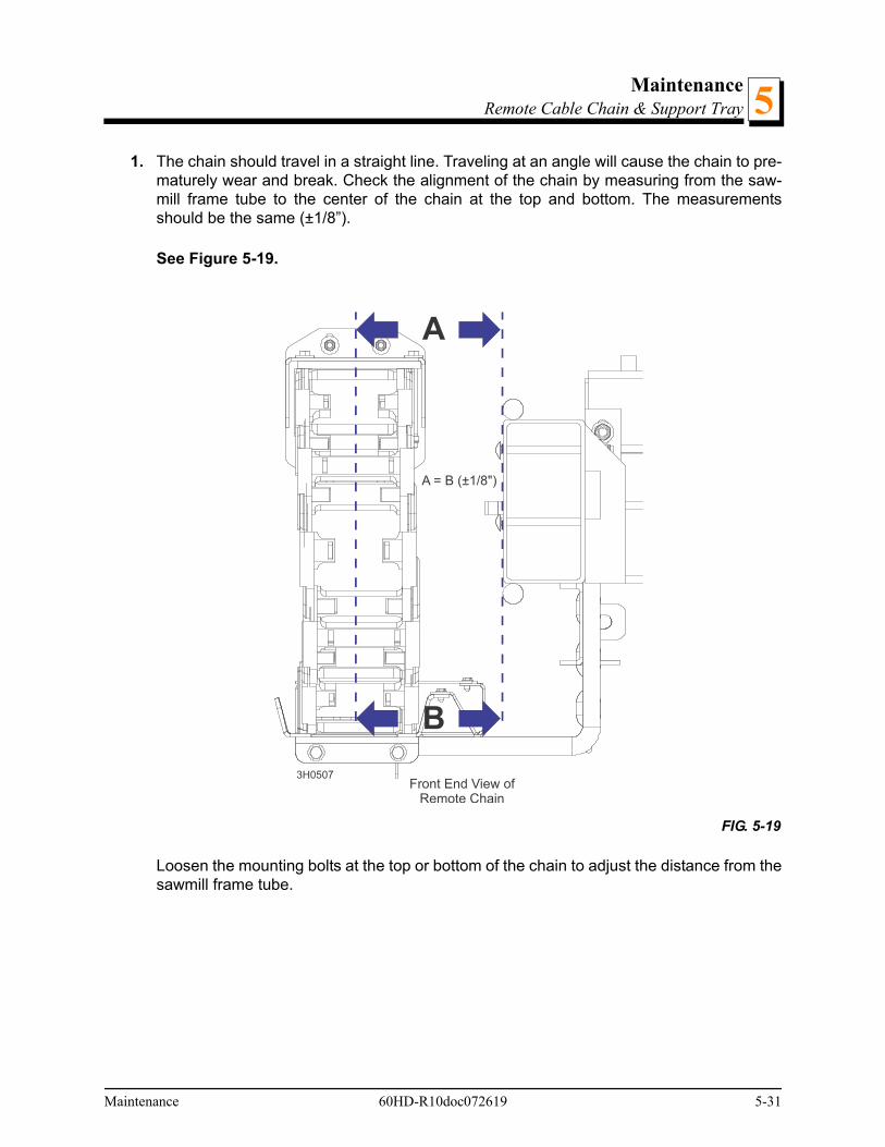
MaintenanceRemote Cable Chain & Support Tray 5
1. The chain should travel in a straight line. Traveling at an angle will cause the chain to pre-maturely wear and break. Check the alignment of the chain by measuring from the saw-mill frame tube to the center of the chain at the top and bottom. The measurementsshould be the same (±1/8”).
See Figure 5-19.
Loosen the mounting bolts at the top or bottom of the chain to adjust the distance from thesawmill frame tube.
FIG. 5-19
A
B
A = B (±1/8")
3H0507Front End View of
Remote Chain
Maintenance 60HD-R10doc072619 5-31
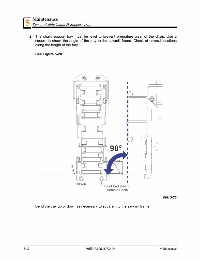
MaintenanceRemote Cable Chain & Support Tray5
2. The chain support tray must be level to prevent premature wear of the chain. Use asquare to check the angle of the tray to the sawmill frame. Check at several locationsalong the length of the tray.
See Figure 5-20.
Bend the tray up or down as necessary to square it to the sawmill frame.
FIG. 5-20
90°
3H0508Front End View of
Remote Chain
5-32 60HD-R10doc072619 Maintenance

MaintenanceMaintenance chart
Maintenance 60HD-R10doc072619 5-33
55.18 Maintenance chart
MAINTENANCE LOG(Check Engine And Option Manuals for additional
maintenance procedures)
MANUALREFERENCE
MAINTENANCE INTERVAL
Clean sawdust from hydraulic loader fuses , battery box lid & track cover
See Section 5.3 8 hours
Clean and lubricate top/bottom track See Section 5.4 8 hours
Check blade guide Block/roller wear See Section 5.2 8 hoursEvery blade change
Remove excess sawdust from blade wheel housings and sawdust chute
See Section 5.3 8 hoursEvery blade change
Inspect fingers inside sawdust chute See Section 5.3 8 hoursEvery blade change
Remove sawdust from upper track roller housings See Section 5.4 25 hours
Check Blade Guide Block Spacing See Section 5.2 25 Hours
Clean and lubricate upper track wiper See Section 5.4 25 hours
Clean & lube mast rails See Section 5.5 50 hours
Lubricate drum switches (Except DCS) See Section 5.6 50 hours
Grease pivot points and bearings/oil chains See Section 5.7 50 hours
Rotate drive/idle blade wheel belts/check for wear See Section 5.9 50 hours
Inspect hydraulic lines & fittings See Section 5.13 50 hours
Check belt tensions See Section 5.10See Section 5.14
50 hours
Check hydraulic fluid level See Section 5.13 50 hours
Check feed & up/down chain tensions See Section 5.14See Section 5.15
50 hours
Check up/down & power feed gear box fluid levels See Section 5.14See Section
5.15
50 hours
Check brake pads See Section 5.11 200 hours
Re-check belt tensions See Section 5.10See Section 5.14
200 hours
Check blade throat screw See Section 5.2 500 hours
Replace hydraulic system filter See Section 5.13 500 hours
Inspect hydraulic pump, power feed and up/down motor brushes
See Section 5.13See Section 5.14See Section 5.15
750 hours
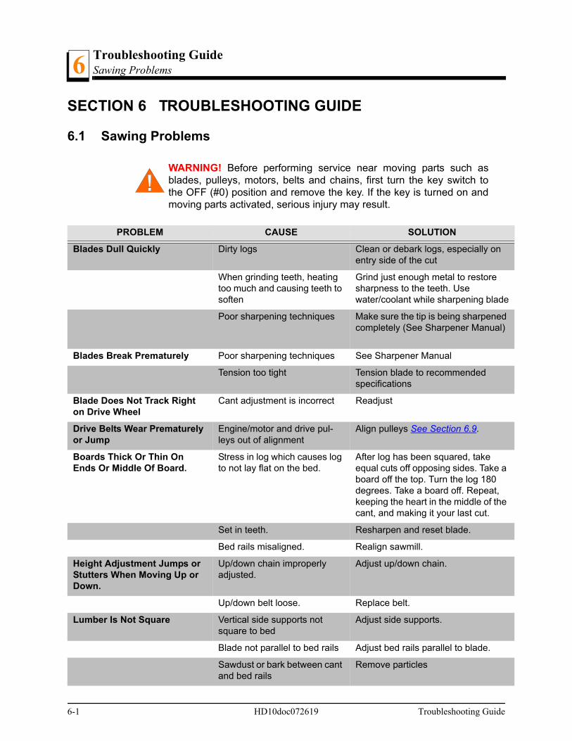
Troubleshooting GuideSawing Problems6
SECTION 6 TROUBLESHOOTING GUIDE
6.1 Sawing Problems
WARNING! Before performing service near moving parts such asblades, pulleys, motors, belts and chains, first turn the key switch tothe OFF (#0) position and remove the key. If the key is turned on andmoving parts activated, serious injury may result.
PROBLEM CAUSE SOLUTION
Blades Dull Quickly Dirty logs Clean or debark logs, especially on entry side of the cut
When grinding teeth, heating too much and causing teeth to soften
Grind just enough metal to restore sharpness to the teeth. Use water/coolant while sharpening blade
Poor sharpening techniques Make sure the tip is being sharpened completely (See Sharpener Manual)
Blades Break Prematurely Poor sharpening techniques See Sharpener Manual
Tension too tight Tension blade to recommended specifications
Blade Does Not Track Right on Drive Wheel
Cant adjustment is incorrect Readjust
Drive Belts Wear Prematurely or Jump
Engine/motor and drive pul-leys out of alignment
Align pulleys See Section 6.9.
Boards Thick Or Thin On Ends Or Middle Of Board.
Stress in log which causes log to not lay flat on the bed.
After log has been squared, take equal cuts off opposing sides. Take a board off the top. Turn the log 180 degrees. Take a board off. Repeat, keeping the heart in the middle of the cant, and making it your last cut.
Set in teeth. Resharpen and reset blade.
Bed rails misaligned. Realign sawmill.
Height Adjustment Jumps or Stutters When Moving Up or Down.
Up/down chain improperly adjusted.
Adjust up/down chain.
Up/down belt loose. Replace belt.
Lumber Is Not Square Vertical side supports not square to bed
Adjust side supports.
Blade not parallel to bed rails Adjust bed rails parallel to blade.
Sawdust or bark between cant and bed rails
Remove particles
6-1 HD10doc072619 Troubleshooting Guide

Troubleshooting GuideSawing Problems 6
Tooth set problems Resharpen and reset blade
Sawdust Builds Up On Track Excessive oiling Do not oil track
Track wipers worn Adjust wipers to firmly contact track
Track is sticky Clean track with solvent and apply silicone spray
Wavy Cuts Excessive feed Slow feed rate
Improperly sharpened blade (This will be the problem 99% of the time!)
Resharpen blade (See Sharpener Manual - read entire manual!)
Blade guides improperly adjusted
Adjust blade guides.
Sap buildup on blade Use Water Lube.
Tooth set problem Resharpen and reset blade
PROBLEM CAUSE SOLUTION
Troubleshooting Guide HD10doc072619 6-2
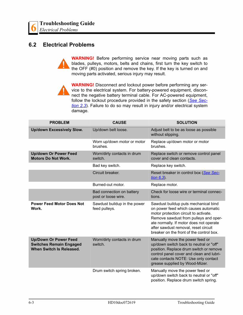
Troubleshooting GuideElectrical Problems6
l
c-
r-
e i-
6.2 Electrical Problems
WARNING! Before performing service near moving parts such asblades, pulleys, motors, belts and chains, first turn the key switch tothe OFF (#0) position and remove the key. If the key is turned on andmoving parts activated, serious injury may result.
WARNING! Disconnect and lockout power before performing any ser-vice to the electrical system. For battery-powered equipment, discon-nect the negative battery terminal cable. For AC-powered equipment,follow the lockout procedure provided in the safety section (See Sec-tion 2.3). Failure to do so may result in injury and/or electrical systemdamage.
PROBLEM CAUSE SOLUTION
Up/down Excessively Slow. Up/down belt loose. Adjust belt to be as loose as possible without slipping.
Worn up/down motor or motor brushes.
Replace up/down motor or motor brushes.
Up/down Or Power Feed Motors Do Not Work.
Worn/dirty contacts in drum switch.
Replace switch or remove control panecover and clean contacts.
Bad key switch. Replace key switch.
Circuit breaker. Reset breaker in control box (See Sec-tion 6.3).
Burned-out motor. Replace motor.
Bad connection on battery post or loose wire.
Check for loose wire or terminal connetions.
Power Feed Motor Does Not Work.
Sawdust buildup in the power feed pulleys.
Sawdust buildup puts mechanical bindon power feed which causes automaticmotor protection circuit to activate. Remove sawdust from pulleys and opeate normally. If motor does not operateafter sawdust removal, reset circuit breaker on the front of the control box.
Up/Down Or Power Feed Switches Remain Engaged When Switch Is Released.
Worn/dirty contacts in drum switch.
Manually move the power feed or up/down switch back to neutral or "off" position. Replace drum switch or removcontrol panel cover and clean and lubrcate contacts NOTE: Use only contact grease supplied by Wood-Mizer.
Drum switch spring broken. Manually move the power feed or up/down switch back to neutral or "off" position. Replace drum switch spring.
6-3 HD10doc072619 Troubleshooting Guide
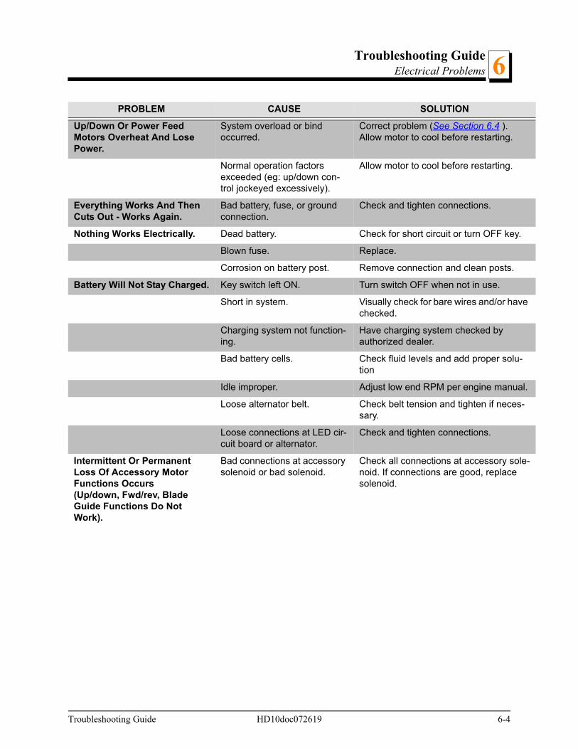
Troubleshooting GuideElectrical Problems 6
e
-
l.
-
le-
Up/Down Or Power Feed Motors Overheat And Lose Power.
System overload or bind occurred.
Correct problem (See Section 6.4 ). Allow motor to cool before restarting.
Normal operation factors exceeded (eg: up/down con-trol jockeyed excessively).
Allow motor to cool before restarting.
Everything Works And Then Cuts Out - Works Again.
Bad battery, fuse, or ground connection.
Check and tighten connections.
Nothing Works Electrically. Dead battery. Check for short circuit or turn OFF key.
Blown fuse. Replace.
Corrosion on battery post. Remove connection and clean posts.
Battery Will Not Stay Charged. Key switch left ON. Turn switch OFF when not in use.
Short in system. Visually check for bare wires and/or havchecked.
Charging system not function-ing.
Have charging system checked by authorized dealer.
Bad battery cells. Check fluid levels and add proper solution
Idle improper. Adjust low end RPM per engine manua
Loose alternator belt. Check belt tension and tighten if necessary.
Loose connections at LED cir-cuit board or alternator.
Check and tighten connections.
Intermittent Or Permanent Loss Of Accessory Motor Functions Occurs (Up/down, Fwd/rev, Blade Guide Functions Do Not Work).
Bad connections at accessory solenoid or bad solenoid.
Check all connections at accessory sonoid. If connections are good, replace solenoid.
PROBLEM CAUSE SOLUTION
Troubleshooting Guide HD10doc072619 6-4
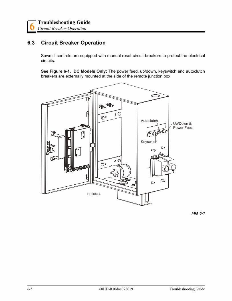
Troubleshooting GuideCircuit Breaker Operation6
6.3 Circuit Breaker Operation
Sawmill controls are equipped with manual reset circuit breakers to protect the electricalcircuits.
See Figure 6-1. DC Models Only: The power feed, up/down, keyswitch and autoclutchbreakers are externally mounted at the side of the remote junction box.
FIG. 6-1
HD0845-4
Up/Down &Power Feed
Autoclutch
Keyswitch
6-5 60HD-R10doc072619 Troubleshooting Guide
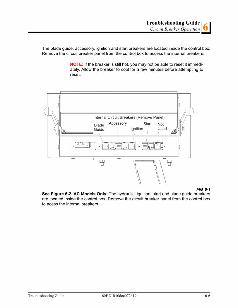
Troubleshooting GuideCircuit Breaker Operation 6
The blade guide, accessory, ignition and start breakers are located inside the control box.Remove the circuit breaker panel from the control box to access the internal breakers.
NOTE: If the breaker is still hot, you may not be able to reset it immedi-ately. Allow the breaker to cool for a few minutes before attempting toreset.
See Figure 6-2. AC Models Only: The hydraulic, ignition, start and blade guide breakersare located inside the control box. Remove the circuit breaker panel from the control boxto acess the internal breakers.
FIG. 6-1
Internal Circuit Breakers (Remove Panel)
BladeGuide
AccessoryIgnition
Start NotUsed
Troubleshooting Guide 60HD-R10doc072619 6-6

Troubleshooting GuideCircuit Breaker Operation6
FIG. 6-2 AC MODELS ONLY
Internal Circuit Breakers (Remove Panel)
Hydraulics
IgnitionStart
Blade Guide NotUsed
6-7 60HD-R10doc072619 Troubleshooting Guide
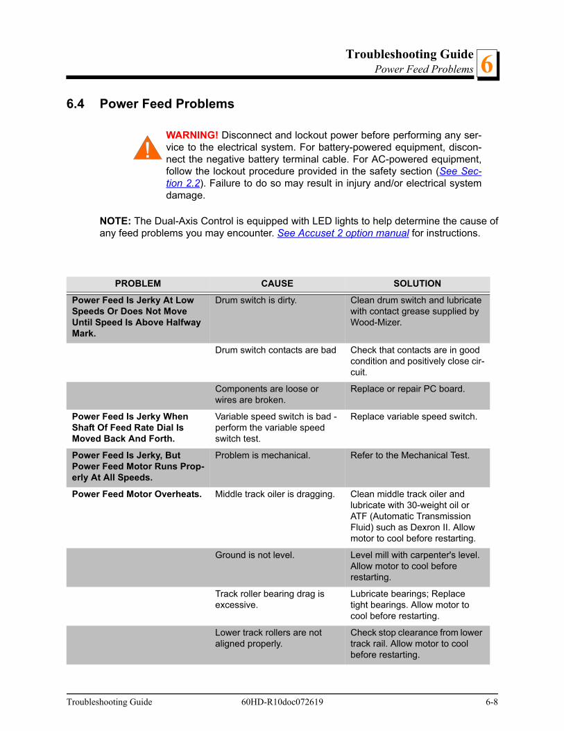
Troubleshooting GuidePower Feed Problems 6
6.4 Power Feed Problems
WARNING! Disconnect and lockout power before performing any ser-vice to the electrical system. For battery-powered equipment, discon-nect the negative battery terminal cable. For AC-powered equipment,follow the lockout procedure provided in the safety section (See Sec-tion 2.2). Failure to do so may result in injury and/or electrical systemdamage.
NOTE: The Dual-Axis Control is equipped with LED lights to help determine the cause ofany feed problems you may encounter. See Accuset 2 option manual for instructions.
PROBLEM CAUSE SOLUTION
Power Feed Is Jerky At Low Speeds Or Does Not Move Until Speed Is Above Halfway Mark.
Drum switch is dirty. Clean drum switch and lubricate with contact grease supplied by Wood-Mizer.
Drum switch contacts are bad Check that contacts are in good condition and positively close cir-cuit.
Components are loose or wires are broken.
Replace or repair PC board.
Power Feed Is Jerky When Shaft Of Feed Rate Dial Is Moved Back And Forth.
Variable speed switch is bad - perform the variable speed switch test.
Replace variable speed switch.
Power Feed Is Jerky, But Power Feed Motor Runs Prop-erly At All Speeds.
Problem is mechanical. Refer to the Mechanical Test.
Power Feed Motor Overheats. Middle track oiler is dragging. Clean middle track oiler and lubricate with 30-weight oil or ATF (Automatic Transmission Fluid) such as Dexron II. Allow motor to cool before restarting.
Ground is not level. Level mill with carpenter's level. Allow motor to cool before restarting.
Track roller bearing drag is excessive.
Lubricate bearings; Replace tight bearings. Allow motor to cool before restarting.
Lower track rollers are not aligned properly.
Check stop clearance from lower track rail. Allow motor to cool before restarting.
Troubleshooting Guide 60HD-R10doc072619 6-8
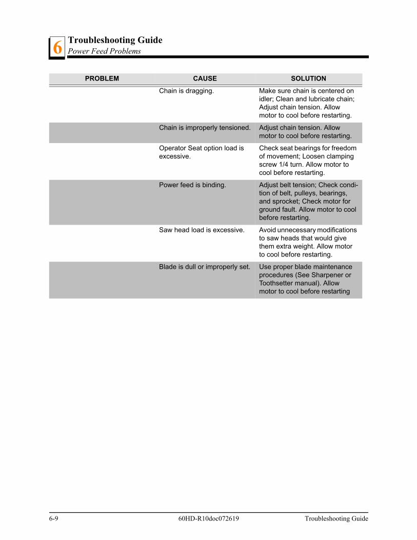
Troubleshooting GuidePower Feed Problems6
Chain is dragging. Make sure chain is centered on idler; Clean and lubricate chain; Adjust chain tension. Allow motor to cool before restarting.
Chain is improperly tensioned. Adjust chain tension. Allow motor to cool before restarting.
Operator Seat option load is excessive.
Check seat bearings for freedom of movement; Loosen clamping screw 1/4 turn. Allow motor to cool before restarting.
Power feed is binding. Adjust belt tension; Check condi-tion of belt, pulleys, bearings, and sprocket; Check motor for ground fault. Allow motor to cool before restarting.
Saw head load is excessive. Avoid unnecessary modifications to saw heads that would give them extra weight. Allow motor to cool before restarting.
Blade is dull or improperly set. Use proper blade maintenance procedures (See Sharpener or Toothsetter manual). Allow motor to cool before restarting
PROBLEM CAUSE SOLUTION
6-9 60HD-R10doc072619 Troubleshooting Guide

Troubleshooting GuidePower Feed Variable Feed Rate Switch Test
Troubleshooting Guide HD10doc072619 6-10
66.5 Power Feed Variable Feed Rate Switch Test
With the feed rate dial switch all the way down, move the shaft of the dial back and forthto see if there is a jerky response. Turn the dial and move the shaft back and forth again.Repeat several times. If the jerkiness occurs at the same location on the dial severaltimes, you need to replace the variable speed switch.
WARNING! Disconnect and lockout power before performing any ser-vice to the electrical system. For battery-powered equipment, discon-nect the negative battery terminal cable. For AC-powered equipment,follow the lockout procedure provided in the safety section (See Sec-tion 2.3). Failure to do so may result in injury and/or electrical systemdamage.

Troubleshooting GuidePower Feed Mechanical Test6
6-11 60HD-R10doc072619 Troubleshooting Guide
6.6 Power Feed Mechanical Test
1. Remove the weight from the track rollers. They should turn smoothly and easily with verylittle play.
2. Make sure the middle track cover is not bent or touching the top rail.
3. Make sure the middle track oiler is free of sawdust buildup.
4. Make sure the power feed chain is not stiff from rust. Also make sure the chain is not tootight.
5. Make sure there is no sap or rust on the rails.
6. Make sure the stop on the lower track roller assembly is not rubbing the lower rail. Alsomake sure the track rollers are not too tight.
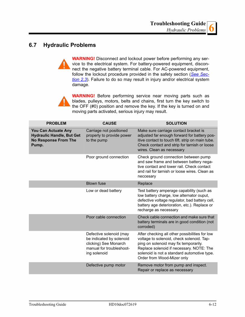
Troubleshooting GuideHydraulic Problems 6
6.7 Hydraulic Problems
WARNING! Disconnect and lockout power before performing any ser-vice to the electrical system. For battery-powered equipment, discon-nect the negative battery terminal cable. For AC-powered equipment,follow the lockout procedure provided in the safety section (See Sec-tion 2.3). Failure to do so may result in injury and/or electrical systemdamage.
WARNING! Before performing service near moving parts such asblades, pulleys, motors, belts and chains, first turn the key switch tothe OFF (#0) position and remove the key. If the key is turned on andmoving parts activated, serious injury may result.
PROBLEM CAUSE SOLUTION
You Can Actuate Any Hydraulic Handle, But Get No Response From The Pump.
Carriage not positioned properly to provide power to the pump
Make sure carriage contact bracket is adjusted far enough forward for battery pos-itive contact to touch 6ft. strip on main tube. Check contact and strip for tarnish or loose wires. Clean as necessary
Poor ground connection Check ground connection between pump and saw frame and between battery nega-tive contact and lower rail. Check contact and rail for tarnish or loose wires. Clean as neccesary
Blown fuse Replace
Low or dead battery Test battery amperage capability (such as low battery charge, low alternator ouput, defective voltage regulator, bad battery cell, battery age deterioration, etc.). Replace or recharge as necessary
Poor cable connection Check cable connection and make sure that battery terminals are in good condition (not corroded)
Defective solenoid (may be indicated by solenoid clicking) See Monarch manual for troubleshoot-ing solenoid
After checking all other possibilities for low voltage to solenoid, check solenoid. Tap-ping on solenoid may fix temporarily. Replace solenoid if necessary. NOTE: The solenoid is not a standard automotive type. Order from Wood-Mizer only
Defective pump motor Remove motor from pump and inspect. Repair or replace as necessary
Troubleshooting Guide HD10doc072619 6-12

Troubleshooting GuideHydraulic Problems6
You Can Get Response From the Pump By Actuat-ing All But One or Two Handles
Valve assembly switch contacts are not properly adjusted
Locate the valve switch at the bottom of the valve assembly. Use a 3MM allen wrench to loosen the set screw on each of the five switch contacts. Press each contact to the valve block and tighten the contact set screw to secure in place. CAUTION! Do not overtighten!
NOTE: Do not adjust the valve switch or switch spring; they have been preset at the factory.
Pump Motor Runs With Little Or No Response From The Cylinders
Low battery Test battery. Recharge or replace as neces-sary
Low fluid level Check fluid level. Add an all-season hydraulic fluid such as Amoco Rycon Oil MV or Mobil Multipurpose ATF (automatic transmission fluid)until level is 4 - 4 1/2" (100 - 114mm) from bottom of reservoir with all cylinders retracted
Pressure relief valve moved from proper setting
Adjust pressure relief valve.
Low air temperature caus-ing fluid to thicken
Allow fluid to warm up. Synthetic fluids are available that allow for hydraulic operation in cold weather conditions (Univis HVI 13)
Pump Motor Runs Contin-uously When Power Con-tact Is Made
Solenoid is stuck closed Tapping the solenoid may solve this prob-lem temporarily. Replace solenoid
Fluid Leaks From Around Cylinder Piston Ram
Worn seals Replace seals in cylinder. Check piston ram for abrasive weld that may be causing pre-mature seal failure
Fluid Leak Around Pump Box
Loose seal or fitting Wipe pump off completely to locate cause of leak. You may have to unbolt the pump to wipe behind it. NOTE: Movement of the sawmill can cause fluid to slosh up into the foam filter in the reservoir cap, and subse-quently spray out, giving the appearance that fluid is leaking from the pump
Hydraulic Side Supports Go Down Before Or At Same Time As Log Turner
Dirt in sequence valve Remove sequence valves and clean thor-oughly with kerosene. NOTE: Be sure to reassemble the valve and install it in its original position on the cylinder
Retainer in sequence valve worn
Replace sequence valve
PROBLEM CAUSE SOLUTION
6-13 HD10doc072619 Troubleshooting Guide
Troubleshooting GuideHydraulic Problems 6
Low air temperature caus-ing fluid to thicken
Allow fluid to warm up. Synthetic fluids are available that allow for hydraulic operation in cold weather conditions (Univis HVI 13)
Hydraulic Turner Goes Up Before Or At Same Time As Side Supports
Dirt in sequence valve Remove sequence valves and clean thor-oughly with kerosene. NOTE: Be sure to reassemble the valve and install it in its original position on the cylinder
Retainer in sequence valve worn
Replace sequence valve
Low air temperature caus-ing fluid to thicken
Allow fluid to warm up. Synthetic fluids are available that allow for hydraulic operation in cold weather conditions. (Univis HVI 13)
Hydraulic Toe Boards "Creep" UP OR DOWN without the valve control handles being operated OR do not raise or lower at all..
Can be a result of shock load caused by improperly using the toe boards to "cushion" or break the fall of a cant onto the bed): ꞏ damaged hosesꞏ damaged cylinder seals or cylinderꞏ damaged valve
INITIAL CHECKTo check, disconnect the toe board hydrau-lic hose from its current valve section and temporarily connect it to another valve sec-tion. Check to see if the hydraulics operate properly.
If hydraulics operate properly, hoses and cylinder seals are good. Perform further valve inspection, found below.
If creep still occurs, check all hoses for possible pinholes causing leakage. Replace if applicable. Retest. If creep still occurs, replace cylinder seals or cylinder and retest.
Be sure to reconnect the hose to the proper valve section when done.
FURTHER VALVE INSPECTIONIf further inspection of the valve is required after initial check, remove the check valve shown below. Flush the check valve with an air hose or solvent to remove any dirt from the valve's seat. Reinstall and test again. Check to see if the hydraulics operate prop-erly.
If creep still occurs, replace the check valve with a new one. Retest. If creep still occurs, replace the hydraulic valve.
PROBLEM CAUSE SOLUTION
Troubleshooting Guide HD10doc072619 6-14

Troubleshooting GuideHydraulic Problems6
Bad check valve (results in one of the toe boards experiencing down-creep)
Check the release valve as instructed above. If the release valve is good, replace the high-pressure hydraulic check valves (A12869) located on the pump.
Pump runs but makes “growling” sound and hydraulic functions are slow, jerky or don’t work at all.
Low fluid level Check fluid level and add fluid as neces-sary. Check for leaks in the system at the control box fittings, hoses and cylinders
One of the log loader cyl-inders does not move when lowering the loader causing the foot of other to raise completely before loader will start down.
Damaged cylinder shaft Replace the cylinder that is not moving
PROBLEM CAUSE SOLUTION
6-15 HD10doc072619 Troubleshooting Guide

Troubleshooting GuideHydraulic Pressure Test
Troubleshooting Guide 60HD-R10doc072619 6-16
66.8 Hydraulic Pressure Test
TO CHECK HYDRAULIC PRESSURE:
See Figure 6-3.
Operate the loading arm hydraulic lever and read the pressure on the gauge. Hydraulicpressure is factory-set at 2200 psi and should not need to be readjusted. The relief valveadjustment screw shown may be used to fine-tune the hydraulic pressure:
Remove the adjustment screw nut. Tighten the adjustment screw (clockwise) to increasepressure. Loosen the adjustment screw (counterclockwise) to lower pressure.
CAUTION! Pressure should not exceed 2200 psi. If it does, the ampdraw will rise above the design maximum of 200 amps, and couldcause battery and system problems. Pressure above 2200 psi mayalso damage the hydraulic hoses.
FIG. 6-3
HydraulicPressureGauge
Relief ValveAdjustment Screw
600200-2
Troubleshooting GuideEngine/Motor and Drive Pulleys Alignment6
6-17 60HD-R10doc072619 Troubleshooting Guide
6.9 Engine/Motor and Drive Pulleys Alignment
WARNING! Before performing service near moving parts such asblades, pulleys, motors, belts and chains, first turn the key switch tothe OFF (#0) position and remove the key. If the key is turned on andmoving parts activated, serious injury may result.
WARNING! Do not for any reason adjust the engine drive belts or beltsupport bracket with the engine running. Doing so may result in seri-ous injury.
1. Install and properly tension the drive belt (See Section 5.10).
2. With the autoclutch disengaged, use a straight edge to check the alignment of the pulleyon the engine/motor to the alternator pulley. Loosen the bushing on the engine/motor pul-ley and adjust if necessary until it is aligned with the alternator pulley.
3. With the autoclutch disengaged, use a straight edge to check the alignment of theengine/motor pulley to the main drive pulley. Loosen the bushing on the drive pulley andadjust if necessary until it is aligned with the engine/motor pulley.
4. (E25/E30 Only): Check that the engine/motor pulley is also square with the drive pulley. Ifneccessary, loosen the engine mounting bolts and cock the engine until the pulley issquare with the drive pulley. Retighten the engine mounting bolts.
5. Check that all engine mounting bolts and pivot bushing clamps are tight.
6. Engage the autoclutch and recheck the pulley alignment. Adjust if necessary.
7. If any pulleys were adjusted, recheck the drive belt support(s) and adjust if neccessary(See Section 5.10).

Sawmill AlignmentRoutine Alignment Procedure 7
SECTION 7 SAWMILL ALIGNMENT
The Wood-Mizer sawmill is factory aligned. Two alignment procedures are available torealign the sawmill if necessary. The Routine Alignment instructions should be performedas necessary to solve sawing problems not related to blade performance. The CompleteAlignment procedure should be performed approximately every 1500 hours of operation(sooner if you regularly transport the sawmill over rough terrain).
7.1 Routine Alignment Procedure
Blade Installation
1. Remove the blade and check the blade wheel belts. Remove any sawdust buildup fromthe surface of the belts. Replace worn belts if they do not keep the blade from contactingthe blade wheel.
2. Install a clean blade and apply the appropriate tension (See Section 3.4).
3. Inspect the blade guide blocks for damage or wear and replace as necessary. Check theblade guide blocks and drive side deflector plate are properly adjusted (See Section 5.2).
4. Adjust the idle-side cant control to track the blade (See Section 3.5).
5. Close the blade housing covers and make sure all persons are clear of the saw head.
6. Start the engine (or motor).
7. Engage the blade, rotating the blade until the blade positions itself on the wheels.
WARNING! Do not spin the blade wheels by hand. Spinning the bladewheels by hand may result in serious injury.
8. Disengage the blade. Turn the engine off and remove the key.
Saw Head Tilt
As the blade enters a wide log or cant, the outside of the saw head will drop down slightly.To compensate for the drop, the saw head is adjusted 1/16" (1.5 mm) higher at the out-side.
1. Move the saw carriage so the blade is positioned over a bed rail. Adjust the blade guidearm to 1/2" (15 mm) from full open.
2. Raise the saw head so the bottom of the blade measures 14 3/4" (375 mm) from the topsurface of the bed rail near the inner blade guide assembly.
Sawmill Alignment 60HD-R10doc072619 7-1

Sawmill AlignmentSaw Head Tilt7
See Figure 7-1.
3. Measure from the blade to the bed rail near the outer blade guide assembly. This mea-surement should be 1/16" (1.5 mm) higher than the inner measurement or 14 13/16"(376.5 mm).
FIG. 7-1
A A + 1/16”
SM0257
7-2 60HD-R10doc072619 Sawmill Alignment

Sawmill AlignmentBlade Guide Arm Alignment 7
See Figure 7-2. To adjust the saw head tilt, use the bolts located at the bottom of the sawhead mast. Loosen the three sets of four retaining plate bolts. To raise the outside of thesaw head, back the stop bolts out, then tighten the adjustment bolts. To lower the outsideof the saw head, loosen the adjustment bolts and tighten the stop bolts. Recheck themeasurement from the blade to the bed rails and adjust the stop bolts and adjustmentbolts until the outside of the saw head is 1/16" (1.5mm) higher than the inside. Retightenthe retaining plate bolts.
Blade Guide Arm Alignment
The blade guide arm moves the outer blade guide in and out. If the arm becomes loose,the blade guide will not deflect the blade properly, causing inaccurate cuts. A loose bladeguide arm can also cause blade vibration.
1. Adjust the blade guide arm in to 1/2" (13 mm) from fully closed.
2. Manually try to move the arm up and down. If you can move the arm by hand, you willneed to tighten the arm rollers.
FIG. 7-2
600011-4B
Stop Bolt
DETAIL OF LOWER TRACK ROLLER ASSEMBLY
Stop BoltAdjustment Bolt
Adjustment BoltRetainingPlate Bolts
Tighten adjustmentbolts to raise saw head;Loosen adjustmentbolts to lower saw head
Sawmill Alignment 60HD-R10doc072619 7-3
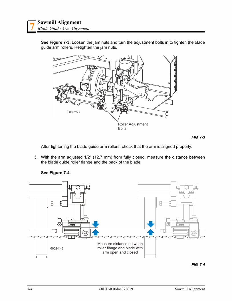
Sawmill AlignmentBlade Guide Arm Alignment7
See Figure 7-3. Loosen the jam nuts and turn the adjustment bolts in to tighten the bladeguide arm rollers. Retighten the jam nuts.
After tightening the blade guide arm rollers, check that the arm is aligned properly.
3. With the arm adjusted 1/2" (12.7 mm) from fully closed, measure the distance betweenthe blade guide roller flange and the back of the blade.
See Figure 7-4.
FIG. 7-3
FIG. 7-4
600025B
Roller AdjustmentBolts
600244-8
Measure distance betweenroller flange and blade with
arm open and closed
7-4 60HD-R10doc072619 Sawmill Alignment

Sawmill AlignmentBlade Guide Arm Alignment 7
4. Adjust the blade guide arm to 1/2" (12.7 mm) from fully open and remeasure the distancefrom the roller flange to the back of the blade. The two measurements should be thesame. If not, adjust the outer rollers in or out to tilt the arm horizontally.
See Figure 7-5. Loosen the horizontal adjustment bolt jam nuts. To tilt the arm in towardthe blade, loosen the rear bolt and tighten the front bolt. To tilt the arm out away from theblade, loosen the front bolt and tighten the rear bolt. Retighten the jam nuts and recheckthe blade guide arm horizontal tilt.
5. Now check the vertical tilt of the blade guide arm. Move the saw carriage so the bladeguide arm is positioned over a bed rail.
6. With the arm 1/2" (13 mm) from fully closed, raise or lower the saw head until the bottomof the blade guide block is 15" (375 mm) from the top of the bed rail.
FIG. 7-5
600025-1B
FrontHorizontal
Adjustment BoltRearHorizontalAdjustment Bolt
Sawmill Alignment 60HD-R10doc072619 7-5

Sawmill AlignmentBlade Guide Arm Alignment7
See Figure 7-6.
7. Adjust the blade guide arm to 1/2" (13 mm) from fully open. Measure the distance fromthe bottom of the blade guide mounting block to the bed rail. This measurement shouldbe 15" (376.5 mm) or slightly higher because the saw head is tilted up 1/16" (1.5 mm) onthe outside (See Saw Head Tilt). If the blade guide is closer to the bed rail or more than1/16" (1.5mm) higher with the arm open, adjust the blade guide arm vertically.
FIG. 7-6
A B
600025-2B
Measure from bladeguide arm to bed rail
with arm open and closed
7-6 60HD-R10doc072619 Sawmill Alignment
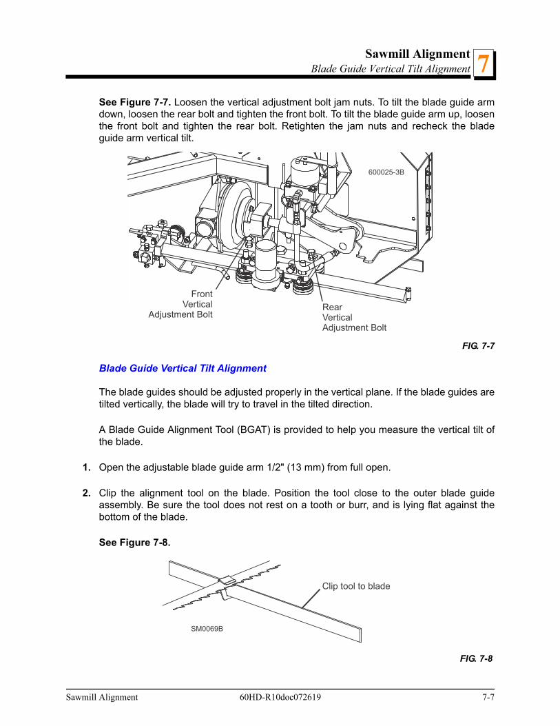
Sawmill AlignmentBlade Guide Vertical Tilt Alignment 7
See Figure 7-7. Loosen the vertical adjustment bolt jam nuts. To tilt the blade guide armdown, loosen the rear bolt and tighten the front bolt. To tilt the blade guide arm up, loosenthe front bolt and tighten the rear bolt. Retighten the jam nuts and recheck the bladeguide arm vertical tilt.
Blade Guide Vertical Tilt Alignment
The blade guides should be adjusted properly in the vertical plane. If the blade guides aretilted vertically, the blade will try to travel in the tilted direction.
A Blade Guide Alignment Tool (BGAT) is provided to help you measure the vertical tilt ofthe blade.
1. Open the adjustable blade guide arm 1/2" (13 mm) from full open.
2. Clip the alignment tool on the blade. Position the tool close to the outer blade guideassembly. Be sure the tool does not rest on a tooth or burr, and is lying flat against thebottom of the blade.
See Figure 7-8.
FIG. 7-7
FIG. 7-8
600025-3B
FrontVertical
Adjustment BoltRearVerticalAdjustment Bolt
SM0069B
Clip tool to blade
Sawmill Alignment 60HD-R10doc072619 7-7

Sawmill AlignmentBlade Guide Horizontal Tilt Adjustment7
3. Move the carriage so that the front end of the tool is positioned above the bed rail. Mea-sure the distance from the bed rail to the bottom edge of the tool.
4. Move the carriage so that the back end of the tool is positioned above the bed rail. Mea-sure the distance from the bed rail to the bottom edge of the tool.
5. If the measurement from the tool to the bed rail is not equal within 1/32" (.75 mm), adjustthe vertical tilt of the outer blade guide roller.
6. Loosen one set screw at the side of the blade guide assembly.
See Figure 7-9. Loosen the jam nuts on the top and bottom vertical tilt adjustmentscrews. To tilt the roller up, loosen the bottom screw and tighten top screw. To tilt the rollerdown, loosen the top screw and tighten the bottom screw. Tighten the jam nuts andrecheck the tilt of the blade.
7. Move the blade guide alignment tool close to the inner blade guide roller assembly andrepeat the above steps. Adjust the vertical tilt of the inner blade guide if necessary.
Blade Guide Horizontal Tilt Adjustment
If the blade guides are tilted in the wrong direction horizontally, the back of the blade maycontact the flange as the roller is spinning down, causing it to push the blade away fromthe guide roller.
8. Remove the blade guide alignment tool from the blade and adjust the blade guide armhalfway in.
FIG. 7-9
600244-5
Top Vertical TiltAdjustment Screw
Bottom Vertical TiltAdjustment Screw
Adjust screws downto tilt roller up; Adjustscrews up to tilt rollerdown
7-8 60HD-R10doc072619 Sawmill Alignment
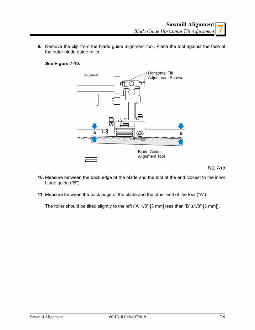
Sawmill AlignmentBlade Guide Horizontal Tilt Adjustment 7
9. Remove the clip from the blade guide alignment tool. Place the tool against the face ofthe outer blade guide roller.
See Figure 7-10.
10. Measure between the back edge of the blade and the tool at the end closest to the innerblade guide ("B").
11. Measure between the back edge of the blade and the other end of the tool ("A").
The roller should be tilted slightly to the left (’A’ 1/8" [3 mm] less than ’B’ ±1/8" [3 mm]).
FIG. 7-10
A B
600244-6Horizontal TiltAdjustment Screws
Blade GuideAlignment Tool
Sawmill Alignment 60HD-R10doc072619 7-9
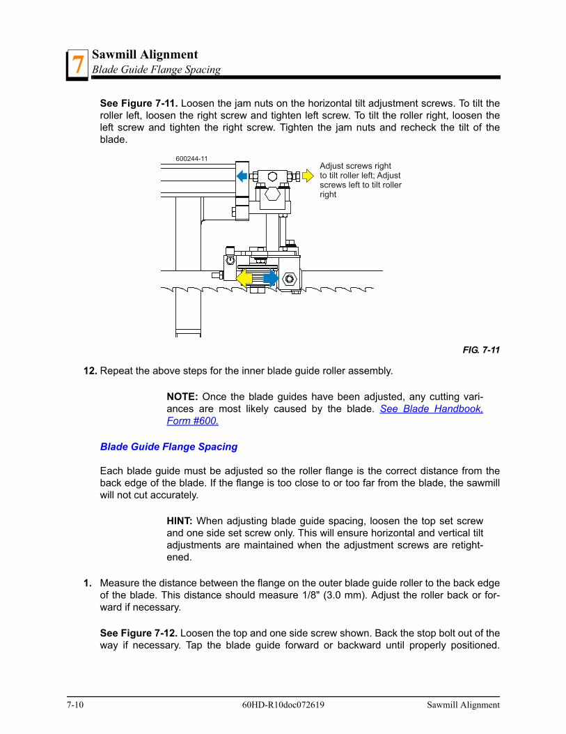
Sawmill AlignmentBlade Guide Flange Spacing7
See Figure 7-11. Loosen the jam nuts on the horizontal tilt adjustment screws. To tilt theroller left, loosen the right screw and tighten left screw. To tilt the roller right, loosen theleft screw and tighten the right screw. Tighten the jam nuts and recheck the tilt of theblade.
12. Repeat the above steps for the inner blade guide roller assembly.
NOTE: Once the blade guides have been adjusted, any cutting vari-ances are most likely caused by the blade. See Blade Handbook,Form #600.
Blade Guide Flange Spacing
Each blade guide must be adjusted so the roller flange is the correct distance from theback edge of the blade. If the flange is too close to or too far from the blade, the sawmillwill not cut accurately.
HINT: When adjusting blade guide spacing, loosen the top set screwand one side set screw only. This will ensure horizontal and vertical tiltadjustments are maintained when the adjustment screws are retight-ened.
1. Measure the distance between the flange on the outer blade guide roller to the back edgeof the blade. This distance should measure 1/8" (3.0 mm). Adjust the roller back or for-ward if necessary.
See Figure 7-12. Loosen the top and one side screw shown. Back the stop bolt out of theway if necessary. Tap the blade guide forward or backward until properly positioned.
FIG. 7-11
600244-11Adjust screws rightto tilt roller left; Adjustscrews left to tilt rollerright
7-10 60HD-R10doc072619 Sawmill Alignment

Sawmill AlignmentManual Side Support Alignment 7
Retighten the screws and jam nuts. Adjust the stop bolt against the blade guide assembly.
2. Measure the distance between the flange on the inner blade guide roller to the back edgeof the blade. This distance should measure 1/16" (1.5 mm). Adjust the roller back or for-ward if necessary.
Manual Side Support Alignment
Logs and boards are clamped against the side supports when sawing. The sides supportsmust be square to the bed to ensure square lumber.
1. Swing a side support down and measure between the face of the support and the mainbed tube. The distance at the top of the side support (’B’) should be equal to or no more
FIG. 7-12
1/16” (Inner Blade Guide)1/8” (Outer Blade Guide)
Loosen top andone side adjustmentscrew
600214-1
Stop Bolt
Sawmill Alignment 60HD-R10doc072619 7-11
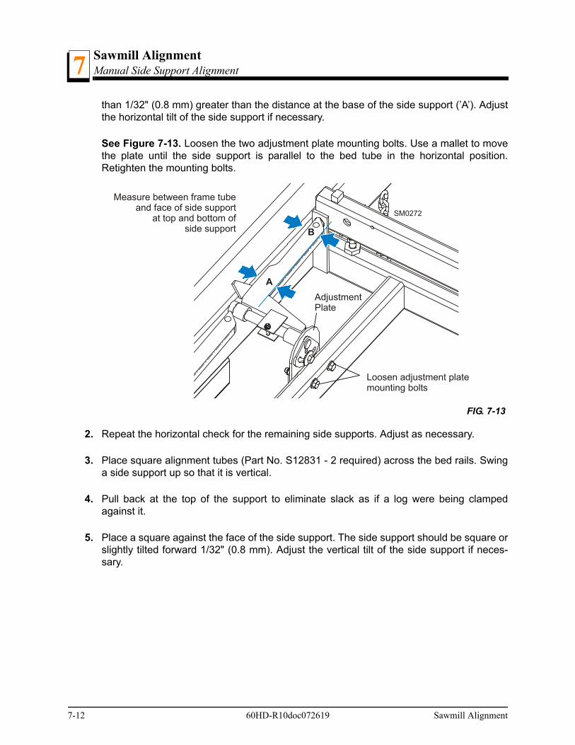
Sawmill AlignmentManual Side Support Alignment7
than 1/32" (0.8 mm) greater than the distance at the base of the side support (’A’). Adjustthe horizontal tilt of the side support if necessary.
See Figure 7-13. Loosen the two adjustment plate mounting bolts. Use a mallet to movethe plate until the side support is parallel to the bed tube in the horizontal position.Retighten the mounting bolts.
2. Repeat the horizontal check for the remaining side supports. Adjust as necessary.
3. Place square alignment tubes (Part No. S12831 - 2 required) across the bed rails. Swinga side support up so that it is vertical.
4. Pull back at the top of the support to eliminate slack as if a log were being clampedagainst it.
5. Place a square against the face of the side support. The side support should be square orslightly tilted forward 1/32" (0.8 mm). Adjust the vertical tilt of the side support if neces-sary.
FIG. 7-13
SM0272
Measure between frame tubeand face of side support
at top and bottom ofside support
A
B
Loosen adjustment platemounting bolts
AdjustmentPlate
7-12 60HD-R10doc072619 Sawmill Alignment

Sawmill AlignmentHydraulic Side Support Alignment 7
See Figure 7-14. Loosen the side support mounting bolt. Use a 3/8" ratchet to rotate thepin until the side support is square to the bed.
6. Repeat the vertical check for the remaining side supports and adjust as necessary.
Hydraulic Side Support Alignment
Place the square against the face of the side support. The side support should be squareor slightly tilted forward 1/32" (0.8 mm). Adjust the vertical tilt of the side support if neces-sary.
FIG. 7-14
SM0272-1
Place squareagainst sidesupport
Loosen mounting bolt
AlignmentTubes (2)
Use 3/8” ratchet to adjustside support mounting pin
Sawmill Alignment 60HD-R10doc072619 7-13

Sawmill AlignmentBlade Height Scale Adjustment (All Mills Except LT70 Super HD)7
See Figure 7-15. Loosen the top jam nut. Adjust the two lower jam nuts up to tilt the sidesupport back. Adjust the two lower jam nuts down to tilt the side support forward.Retighten the top jam nut and repeat for the other hydraulic side support.
Blade Height Scale Adjustment (All Mills Except LT70 Super HD)
After the entire sawmill has been aligned and all adjustments made, check that the bladeheight scale indicates the true distance from the blade to the bed rails.
1. Move the saw carriage so the blade is positioned directly above one of the bed rails. Mea-sure from the bottom edge on a down-set tooth of the blade to the top of the bed rail, nearthe inner blade guide assembly.
2. View the blade height scale with eyes level with the indicator. The scale should indicatethe actual distance from the blade to the bed rail. Adjust the indicator if necessary.
See Figure 7-16. Loosen the scale bracket mounting bolts. Adjust the bracket up or downuntil the indicator is aligned with the correct mark on the scale (+0 -1/32 [0.8 mm]).Retighten the bracket mounting bolts.
FIG. 7-15
600026-1
Place squareagainst sidesupport
AlignmentTubes (2)
Adjust jam nuts upto tilt side support back;Adjust jam nuts downto tilt side support forward
Loosen topjam nut
7-14 60HD-R10doc072619 Sawmill Alignment

Sawmill AlignmentBlade Height Scale Adjustment (All Mills Except LT70 Super HD) 7
For example, if the measurement from the down-set tooth of the blade to the bed rail was14 3/4" (375 mm), make sure the indicator reads 14 3/4" (375 mm) on the scale.
FIG. 7-16
Blade HeightIndicatorScale Bracket
Mounting Bolts
600123-1
Sawmill Alignment 60HD-R10doc072619 7-15
Sawmill AlignmentComplete Alignment Procedure7
7.2 Complete Alignment Procedure
Frame Setup
Before performing the following alignment procedures, setup the mill on firm, levelground.
If your sawmill is stationary, with no trailer axle, shim the feet so the weight of the sawmillis evenly supported.
If your sawmill has a trailer axle and adjustable outriggers, adjust the outriggers as fol-lows:
Adjust the front and third outriggers on the main frame tube down just enough to liftweight from the trailer tire.
All Portable Sawmills: Adjust the two outer outriggers down just so they touch theground but do not bear weight.
See SECTION 3 for additional setup information.
Blade Installation
1. Remove the blade and replace the blade wheel belts. New blade wheel belts are requiredto perform the complete alignment procedure.
2. Blow sawdust off of the blade guide assemblies. Remove sawdust from the blade hous-ings.
3. Remove the blade guide assemblies.
NOTE: To remove the blade guide assemblies and maintain the tiltadjustments, only loosen one side screw and the top screw. Leavingthe other side screw and bottom screw in position will insure you willreturn the rollers to their original tilt adjustment.
4. Adjust the outer blade guide arm in or out until the outer blade guide is approximately 24”from the inner blade guide.
5. Install a new blade and apply the appropriate tension (See Section 3.4).
6. Close the blade housing covers and make sure all persons are clear of the saw head.
7. Start the engine (or motor).
7-16 60HD-R10doc072619 Sawmill Alignment
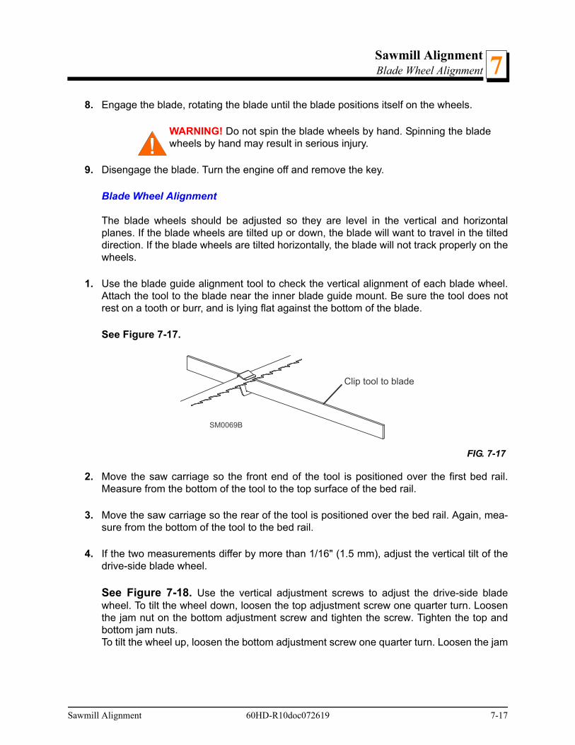
Sawmill AlignmentBlade Wheel Alignment 7
8. Engage the blade, rotating the blade until the blade positions itself on the wheels.
WARNING! Do not spin the blade wheels by hand. Spinning the bladewheels by hand may result in serious injury.
9. Disengage the blade. Turn the engine off and remove the key.
Blade Wheel Alignment
The blade wheels should be adjusted so they are level in the vertical and horizontalplanes. If the blade wheels are tilted up or down, the blade will want to travel in the tilteddirection. If the blade wheels are tilted horizontally, the blade will not track properly on thewheels.
1. Use the blade guide alignment tool to check the vertical alignment of each blade wheel.Attach the tool to the blade near the inner blade guide mount. Be sure the tool does notrest on a tooth or burr, and is lying flat against the bottom of the blade.
See Figure 7-17.
2. Move the saw carriage so the front end of the tool is positioned over the first bed rail.Measure from the bottom of the tool to the top surface of the bed rail.
3. Move the saw carriage so the rear of the tool is positioned over the bed rail. Again, mea-sure from the bottom of the tool to the bed rail.
4. If the two measurements differ by more than 1/16" (1.5 mm), adjust the vertical tilt of thedrive-side blade wheel.
See Figure 7-18. Use the vertical adjustment screws to adjust the drive-side bladewheel. To tilt the wheel down, loosen the top adjustment screw one quarter turn. Loosenthe jam nut on the bottom adjustment screw and tighten the screw. Tighten the top andbottom jam nuts.To tilt the wheel up, loosen the bottom adjustment screw one quarter turn. Loosen the jam
FIG. 7-17
SM0069B
Clip tool to blade
Sawmill Alignment 60HD-R10doc072619 7-17
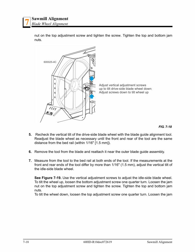
Sawmill AlignmentBlade Wheel Alignment7
nut on the top adjustment screw and tighten the screw. Tighten the top and bottom jamnuts.
5. Recheck the vertical tilt of the drive-side blade wheel with the blade guide alignment tool.Readjust the blade wheel as necessary until the front and rear of the tool are the samedistance from the bed rail (within 1/16" [1.5 mm]).
6. Remove the tool from the blade and reattach it near the outer blade guide assembly.
7. Measure from the tool to the bed rail at both ends of the tool. If the measurements at thefront and rear ends of the tool differ by more than 1/16" (1.5 mm), adjust the vertical tilt ofthe idle-side blade wheel.
See Figure 7-19. Use the vertical adjustment screws to adjust the idle-side blade wheel.To tilt the wheel up, loosen the bottom adjustment screw one quarter turn. Loosen the jamnut on the top adjustment screw and tighten the screw. Tighten the top and bottom jamnuts.To tilt the wheel down, loosen the top adjustment screw one quarter turn. Loosen the jam
FIG. 7-18
600025-4C
Adjust vertical adjustment screwsup to tilt drive-side blade wheel down;Adjust screws down to tilt wheel up
7-18 60HD-R10doc072619 Sawmill Alignment

Sawmill AlignmentBlade Wheel Alignment 7
nut on the bottom adjustment screw and tighten the screw. Tighten the top and bottomjam nuts.
See Figure 7-20. 8. Recheck the vertical tilt of the idle-side blade wheel with the blade guide alignment tool.
Readjust the blade wheel as necessary until the front and rear of the tool are the samedistance from the bed rail (within 1/16" [1.5 mm]).
9. Check the position of the blade on the idle-side blade wheel.
See Figure 7-21. The horizontal tilt of the blade wheel should be adjusted so that the gul-let of an 1-1/4" blade is 1/8" (3 mm) out from the front edge of the wheel (±1/16 [1.5
FIG. 7-19
600025-5B
Adjust vertical adjustmentscrews up to tilt idle-side
blade wheel down; Adjustscrews down to tilt wheel up
Sawmill Alignment 60HD-R10doc072619 7-19

Sawmill AlignmentBlade Wheel Alignment7
mm]).The gullet of an 1-1/2" blade should be 3/16" (4.5 mm) out from the front edge of thewheel (±1/16 [1.5 mm]). Do not let the teeth ride on the wheels.
See Figure 7-22. Use the cant control adjustment to adjust the idle-side blade wheel. Ifthe blade is too far forward on the wheel, turn the cant control counterclockwise. If it is toofar back on the wheel, turn the cant control clockwise.
10. Check the position of the blade on the drive-side blade wheel. The blade should be posi-tioned on the wheel as described for the idle-side blade wheel. Adjust the drive-side bladewheel if necessary.
FIG. 7-21
FIG. 7-22
SM0044D
3/16" (4.5 mm)± 1/16" (1.5 mm)
1 1/2"Blade
1/8" (3.0 mm)± 1/16" (1.5 mm)
1 1/4"Blade
600025-6B
CantControl
Turn cant control clockwise to moveblade out on wheel; counterclockwiseto move blade back on wheel
7-20 60HD-R10doc072619 Sawmill Alignment
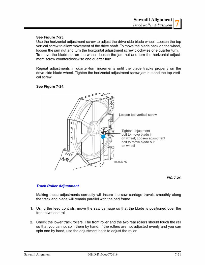
Sawmill AlignmentTrack Roller Adjustment 7
See Figure 7-23. Use the horizontal adjustment screw to adjust the drive-side blade wheel. Loosen the topvertical screw to allow movement of the drive shaft. To move the blade back on the wheel,loosen the jam nut and turn the horizontal adjustment screw clockwise one quarter turn.To move the blade out on the wheel, loosen the jam nut and turn the horizontal adjust-ment screw counterclockwise one quarter turn.
Repeat adjustments in quarter-turn increments until the blade tracks properly on thedrive-side blade wheel. Tighten the horizontal adjustment screw jam nut and the top verti-cal screw.
See Figure 7-24.
Track Roller Adjustment
Making these adjustments correctly will insure the saw carriage travels smoothly alongthe track and blade will remain parallel with the bed frame.
1. Using the feed controls, move the saw carriage so that the blade is positioned over thefront pivot end rail.
2. Check the lower track rollers. The front roller and the two rear rollers should touch the railso that you cannot spin them by hand. If the rollers are not adjusted evenly and you canspin one by hand, use the adjustment bolts to adjust the roller.
FIG. 7-24
600025-7C
Tighten adjustmentbolt to move blade inon wheel; Loosen adjustmentbolt to move blade outon wheel
Loosen top vertical screw
Sawmill Alignment 60HD-R10doc072619 7-21

Sawmill AlignmentTrack Roller Adjustment7
See Figure 7-25.
Loosen the four retaining plate bolts. Back out the stop bolt and tighten the adjustmentbolt to move the track roller(s) toward the rail. When the roller touches the rail so you can-not spin it by hand, retighten the stop bolt and the retaining plate bolts.
Observe the middle upper and lower track rollers as you move the saw carriage down thetrack. The middle rollers should touch the rail throughout most of the saw carriage travel.Be careful not to tighten the rollers so they cause the carriage to bind as it travels downthe track. If the rollers do not spin at least half the distance of the track, tighten them asdescribed above.
3. Open the adjustable blade guide arm to within 1/2" (15 mm) of full open.
4. Move the carriage back to the front pivot end rail. Raise the cutting head until the bottomof the blade is 17" (400 mm) above the outside of the pivot rail support by actual mea-surement with a tape or ruler.
FIG. 7-25
Lower TrackRoller
Lower Stop
Upper TrackRollers
600011-7
Retainer PlateBolts (4)
AdjustmentBolt
Stop Bolt
7-22 60HD-R10doc072619 Sawmill Alignment

Sawmill AlignmentTrack Roller Adjustment 7
See Figure 7-26.
5. Move the carriage forward to check the distance to the blade at the inside of the pivot railsupport. All measurements should be equal within 1/32" (0.8 mm).
See Figure 7-27. To adjust the saw head tilt, use the bolts located at the bottom of thesaw head mast. Loosen the three sets of four retaining plate bolts. To raise the outside ofthe saw head, back the stop bolts out, then tighten the adjustment bolts. To lower the out-
FIG. 7-26
SM0137
17" (400 mm)to blade
Sawmill Alignment 60HD-R10doc072619 7-23

Sawmill AlignmentBed Rail Adjustment7
side of the saw head, loosen the adjustment bolts and tighten the stop bolts. Recheck thesaw head tilt and readjust the bolts as necessary. Retighten the retaining plate bolts.
6. After the lower track rollers are adjusted properly, adjust the upper and lower stop screws.Tighten each screw until it just touches the rail. Then, back the screw off 1/2 turn. The gapwill be approximately 1/32" (0.8mm).
CAUTION! It is important that the lower stop bolts are properlyadjusted to secure the carriage on the track rail. Failure to properlyadjust the stop bolts can cause saw head damage, especially duringmill transportation.
Bed Rail Adjustment
1. Move the clamp so it is 10" (254mm) from the clamp stop. Adjust the clamp down to itslowest postion. Move the saw head forward until it is positioned over the clamp. Raise thesaw head until the blade measures 15 5/16" (385 mm) from the clamp at its lowest posi-tion.
2. Adjust the front pivot rail 90° to the main bed tube.
FIG. 7-27
600011-4B
Stop Bolt
DETAIL OF LOWER TRACK ROLLER ASSEMBLY
Stop BoltAdjustment Bolt
Adjustment BoltRetainingPlate Bolts
Tighten adjustmentbolts to raise saw head;Loosen adjustmentbolts to lower saw head
7-24 60HD-R10doc072619 Sawmill Alignment

Sawmill AlignmentBed Rail Adjustment 7
3. Move the saw head to center the blade over the front pivot bed rail.
4. Measure the distance from the top of the pivot rail to the bottom of the blade. Make thismeasurement at each end of the pivot rail.
5. The two measurements should be 15" (375 mm).
See Figure 7-28. Loosen the locking set screws and turn the inner height adjustment nutto adjust the height of the inner end of the pivot rail. Loosen the jam nut and turn the outeradjustment bolt to adjust the height of the outer end of the pivot rail.
6. Move the saw head so the blade is positioned over the center of the front main bed rail.
7. Measure the distance between the bottom of the blade and the bed rail at each end of thebed rail. The bed rail should measure 15" (375 mm) from the blade at each end of the rail.
FIG. 7-28
SM0134B
Inner HeightAdjustment
Nut
Outer HeightAdjustmentBolt
15" (375mm)to blade
15" (375mm)to blade
Sawmill Alignment 60HD-R10doc072619 7-25
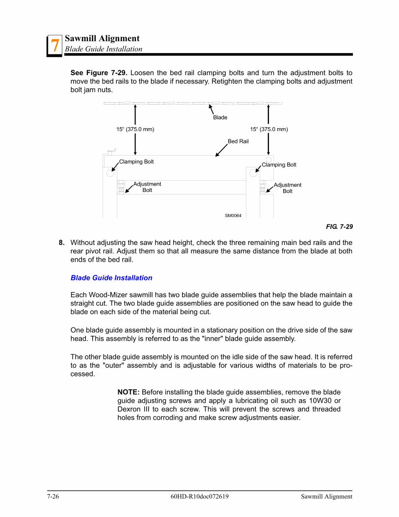
Sawmill AlignmentBlade Guide Installation7
See Figure 7-29. Loosen the bed rail clamping bolts and turn the adjustment bolts tomove the bed rails to the blade if necessary. Retighten the clamping bolts and adjustmentbolt jam nuts.
8. Without adjusting the saw head height, check the three remaining main bed rails and therear pivot rail. Adjust them so that all measure the same distance from the blade at bothends of the bed rail.
Blade Guide Installation
Each Wood-Mizer sawmill has two blade guide assemblies that help the blade maintain astraight cut. The two blade guide assemblies are positioned on the saw head to guide theblade on each side of the material being cut.
One blade guide assembly is mounted in a stationary position on the drive side of the sawhead. This assembly is referred to as the "inner" blade guide assembly.
The other blade guide assembly is mounted on the idle side of the saw head. It is referredto as the "outer" assembly and is adjustable for various widths of materials to be pro-cessed.
NOTE: Before installing the blade guide assemblies, remove the bladeguide adjusting screws and apply a lubricating oil such as 10W30 orDexron III to each screw. This will prevent the screws and threadedholes from corroding and make screw adjustments easier.
FIG. 7-29
15“ (375.0 mm) 15“ (375.0 mm)
Blade
Bed Rail
Clamping BoltClamping Bolt
AdjustmentBolt
AdjustmentBolt
SM0064
7-26 60HD-R10doc072619 Sawmill Alignment
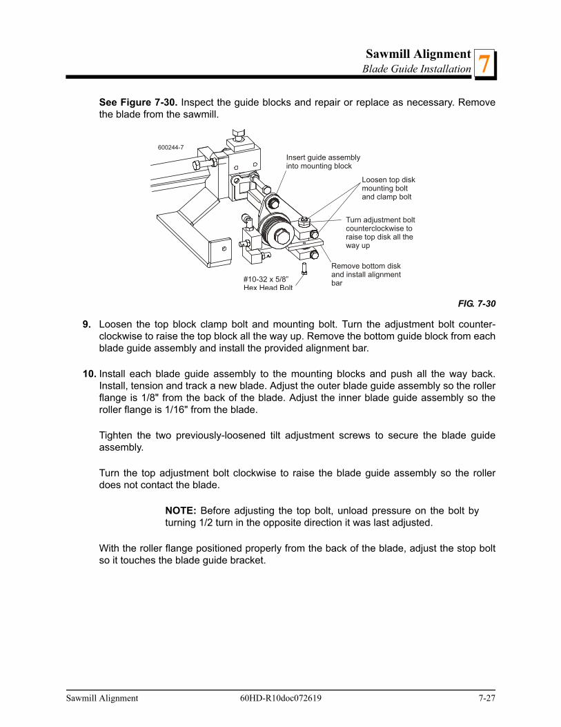
Sawmill AlignmentBlade Guide Installation 7
See Figure 7-30. Inspect the guide blocks and repair or replace as necessary. Removethe blade from the sawmill.
9. Loosen the top block clamp bolt and mounting bolt. Turn the adjustment bolt counter-clockwise to raise the top block all the way up. Remove the bottom guide block from eachblade guide assembly and install the provided alignment bar.
10. Install each blade guide assembly to the mounting blocks and push all the way back.Install, tension and track a new blade. Adjust the outer blade guide assembly so the rollerflange is 1/8" from the back of the blade. Adjust the inner blade guide assembly so theroller flange is 1/16" from the blade.
Tighten the two previously-loosened tilt adjustment screws to secure the blade guideassembly.
Turn the top adjustment bolt clockwise to raise the blade guide assembly so the rollerdoes not contact the blade.
NOTE: Before adjusting the top bolt, unload pressure on the bolt byturning 1/2 turn in the opposite direction it was last adjusted.
With the roller flange positioned properly from the back of the blade, adjust the stop boltso it touches the blade guide bracket.
FIG. 7-30
600244-7
#10-32 x 5/8”Hex Head Bolt
Remove bottom diskand install alignmentbar
Loosen top diskmounting boltand clamp bolt
Insert guide assemblyinto mounting block
Turn adjustment boltcounterclockwise toraise top disk all theway up
Sawmill Alignment 60HD-R10doc072619 7-27
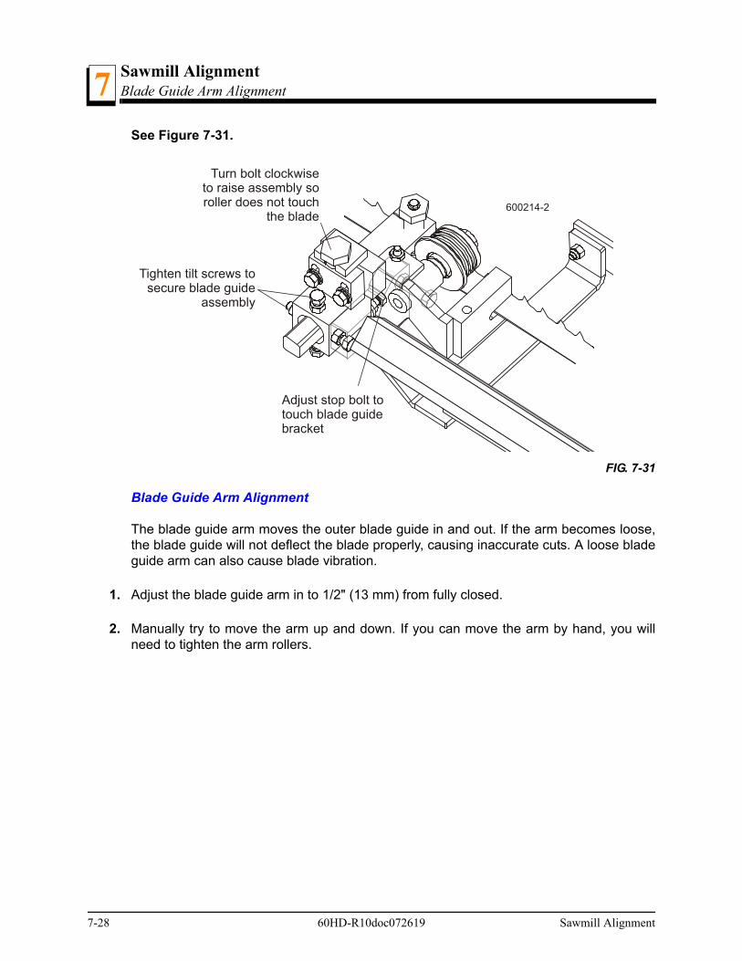
Sawmill AlignmentBlade Guide Arm Alignment7
See Figure 7-31.
Blade Guide Arm Alignment
The blade guide arm moves the outer blade guide in and out. If the arm becomes loose,the blade guide will not deflect the blade properly, causing inaccurate cuts. A loose bladeguide arm can also cause blade vibration.
1. Adjust the blade guide arm in to 1/2" (13 mm) from fully closed.
2. Manually try to move the arm up and down. If you can move the arm by hand, you willneed to tighten the arm rollers.
FIG. 7-31
Turn bolt clockwiseto raise assembly soroller does not touch
the blade600214-2
Tighten tilt screws tosecure blade guide
assembly
Adjust stop bolt totouch blade guidebracket
7-28 60HD-R10doc072619 Sawmill Alignment
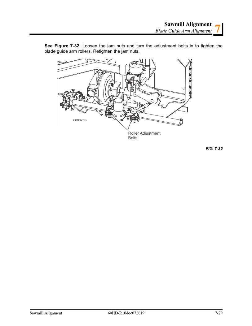
Sawmill AlignmentBlade Guide Arm Alignment 7
See Figure 7-32. Loosen the jam nuts and turn the adjustment bolts in to tighten theblade guide arm rollers. Retighten the jam nuts.
FIG. 7-32
600025B
Roller AdjustmentBolts
Sawmill Alignment 60HD-R10doc072619 7-29
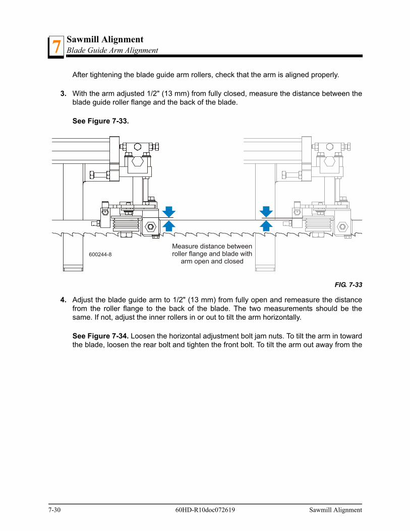
Sawmill AlignmentBlade Guide Arm Alignment7
After tightening the blade guide arm rollers, check that the arm is aligned properly.
3. With the arm adjusted 1/2" (13 mm) from fully closed, measure the distance between theblade guide roller flange and the back of the blade.
See Figure 7-33.
4. Adjust the blade guide arm to 1/2" (13 mm) from fully open and remeasure the distancefrom the roller flange to the back of the blade. The two measurements should be thesame. If not, adjust the inner rollers in or out to tilt the arm horizontally.
See Figure 7-34. Loosen the horizontal adjustment bolt jam nuts. To tilt the arm in towardthe blade, loosen the rear bolt and tighten the front bolt. To tilt the arm out away from the
FIG. 7-33
600244-8
Measure distance betweenroller flange and blade with
arm open and closed
7-30 60HD-R10doc072619 Sawmill Alignment
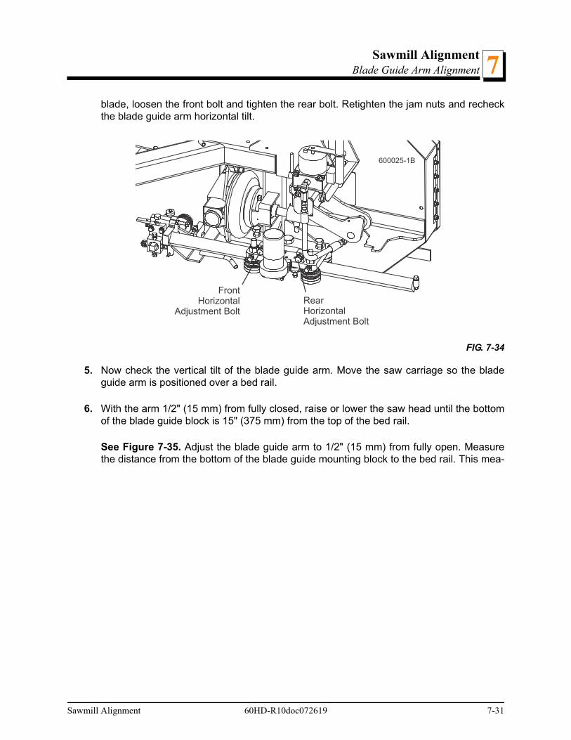
Sawmill AlignmentBlade Guide Arm Alignment 7
blade, loosen the front bolt and tighten the rear bolt. Retighten the jam nuts and recheckthe blade guide arm horizontal tilt.
5. Now check the vertical tilt of the blade guide arm. Move the saw carriage so the bladeguide arm is positioned over a bed rail.
6. With the arm 1/2" (15 mm) from fully closed, raise or lower the saw head until the bottomof the blade guide block is 15" (375 mm) from the top of the bed rail.
See Figure 7-35. Adjust the blade guide arm to 1/2" (15 mm) from fully open. Measurethe distance from the bottom of the blade guide mounting block to the bed rail. This mea-
FIG. 7-34
600025-1B
FrontHorizontal
Adjustment BoltRearHorizontalAdjustment Bolt
Sawmill Alignment 60HD-R10doc072619 7-31
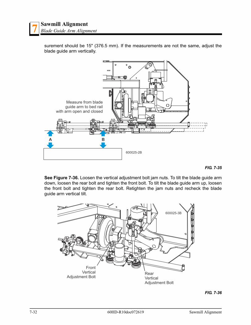
Sawmill AlignmentBlade Guide Arm Alignment7
surement should be 15" (376.5 mm). If the measurements are not the same, adjust theblade guide arm vertically.
See Figure 7-36. Loosen the vertical adjustment bolt jam nuts. To tilt the blade guide armdown, loosen the rear bolt and tighten the front bolt. To tilt the blade guide arm up, loosenthe front bolt and tighten the rear bolt. Retighten the jam nuts and recheck the bladeguide arm vertical tilt.
FIG. 7-35
FIG. 7-36
A B
600025-2B
Measure from bladeguide arm to bed rail
with arm open and closed
600025-3B
FrontVertical
Adjustment BoltRearVerticalAdjustment Bolt
7-32 60HD-R10doc072619 Sawmill Alignment
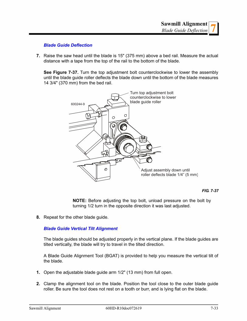
Sawmill AlignmentBlade Guide Deflection 7
Blade Guide Deflection
7. Raise the saw head until the blade is 15" (375 mm) above a bed rail. Measure the actualdistance with a tape from the top of the rail to the bottom of the blade.
See Figure 7-37. Turn the top adjustment bolt counterclockwise to lower the assemblyuntil the blade guide roller deflects the blade down until the bottom of the blade measures14 3/4" (370 mm) from the bed rail.
NOTE: Before adjusting the top bolt, unload pressure on the bolt byturning 1/2 turn in the opposite direction it was last adjusted.
8. Repeat for the other blade guide.
Blade Guide Vertical Tilt Alignment
The blade guides should be adjusted properly in the vertical plane. If the blade guides aretilted vertically, the blade will try to travel in the tilted direction.
A Blade Guide Alignment Tool (BGAT) is provided to help you measure the vertical tilt ofthe blade.
1. Open the adjustable blade guide arm 1/2" (13 mm) from full open.
2. Clamp the alignment tool on the blade. Position the tool close to the outer blade guideroller. Be sure the tool does not rest on a tooth or burr, and is lying flat on the blade.
FIG. 7-37
600244-9
Turn top adjustment boltcounterclockwise to lowerblade guide roller
Adjust assembly down untilroller deflects blade 1/4” (5 mm)
Sawmill Alignment 60HD-R10doc072619 7-33

Sawmill AlignmentBlade Guide Vertical Tilt Alignment7
See Figure 7-38.
3. Move the carriage so that the front end of the tool is positioned above the bed rail. Mea-sure the distance from the bed rail to the bottom edge of the tool.
4. Move the carriage so that the back end of the tool is positioned above the bed rail. Mea-sure the distance from the bed rail to the bottom edge of the tool.
5. If the measurement from the tool to the bed rail is not equal within 1/32" (.75 mm), adjustthe vertical tilt of the outer blade guide roller.
6. Loosen one set screw at the side of the blade guide assembly.
See Figure 7-39. Loosen the jam nuts on the top and bottom vertical tilt adjustmentscrews. To tilt the roller up, loosen the bottom screw and tighten top screw. To tilt the rollerdown, loosen the top screw and tighten the bottom screw. Tighten the jam nuts andrecheck the tilt of the blade.
7. Move the blade guide alignment tool close to the inner blade guide roller assembly andrepeat the above steps. Adjust the vertical tilt of the inner blade guide if necessary.
FIG. 7-38
FIG. 7-39
SM0069B
Clip tool to blade
600244-5
Top Vertical TiltAdjustment Screw
Bottom Vertical TiltAdjustment Screw
Adjust screws downto tilt roller up; Adjustscrews up to tilt rollerdown
7-34 60HD-R10doc072619 Sawmill Alignment

Sawmill AlignmentBlade Guide Horizontal Tilt Adjustment 7
8. After adjusting the vertical tilt of the blade guides, recheck the blade deflection and adjustif necessary.
Blade Guide Horizontal Tilt Adjustment
If the blade guides are tilted in the wrong direction horizontally, the back of the blade maycontact the flange as the roller is spinning down, causing it to push the blade away fromthe guide roller.
1. Remove the blade guide alignment tool from the blade and adjust the blade guide armhalfway in.
2. Remove the clip from the blade guide alignment tool. Place the tool against the face ofthe outer blade guide roller.
See Figure 7-40.
3. Measure between the back edge of the blade and the tool at the end closest to the innerblade guide ("B").
4. Measure between the back edge of the blade and the other end of the tool ("A").
The roller should be tilted slightly to the left (’A’ 1/8" [3 mm] less than ’B’ ±1/8" [3 mm]).
5. Loosen the jam nuts on the horizontal tilt adjustment screws. To tilt the roller left, loosenthe right screw and tighten left screw. To tilt the roller right, loosen the left screw andtighten the right screw. Tighten the jam nuts and recheck the tilt of the blade. Repeat theabove steps for the inner blade guide roller assembly.
FIG. 7-40
A B
600244-6Horizontal TiltAdjustment Screws
Blade GuideAlignment Tool
Sawmill Alignment 60HD-R10doc072619 7-35
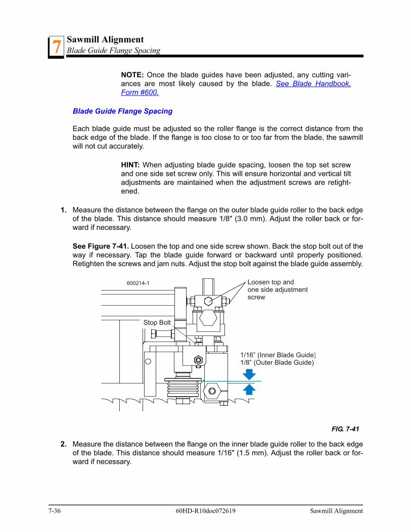
Sawmill AlignmentBlade Guide Flange Spacing7
NOTE: Once the blade guides have been adjusted, any cutting vari-ances are most likely caused by the blade. See Blade Handbook,Form #600.
Blade Guide Flange Spacing
Each blade guide must be adjusted so the roller flange is the correct distance from theback edge of the blade. If the flange is too close to or too far from the blade, the sawmillwill not cut accurately.
HINT: When adjusting blade guide spacing, loosen the top set screwand one side set screw only. This will ensure horizontal and vertical tiltadjustments are maintained when the adjustment screws are retight-ened.
1. Measure the distance between the flange on the outer blade guide roller to the back edgeof the blade. This distance should measure 1/8" (3.0 mm). Adjust the roller back or for-ward if necessary.
See Figure 7-41. Loosen the top and one side screw shown. Back the stop bolt out of theway if necessary. Tap the blade guide forward or backward until properly positioned.Retighten the screws and jam nuts. Adjust the stop bolt against the blade guide assembly.
2. Measure the distance between the flange on the inner blade guide roller to the back edgeof the blade. This distance should measure 1/16" (1.5 mm). Adjust the roller back or for-ward if necessary.
FIG. 7-41
1/16” (Inner Blade Guide)1/8” (Outer Blade Guide)
Loosen top andone side adjustmentscrew
600214-1
Stop Bolt
7-36 60HD-R10doc072619 Sawmill Alignment

Sawmill AlignmentBlade Guide Level 7
Blade Guide Level
Perform the following adjustments to make sure the blade guide assembly is parallel tothe blade.
1. Loosen the alignment bar mounting bolt. Use the provided bottom block adjustment toolto adjust the alignment bar up so the bar is close to, but not touching the bottom of theblade. Retighten the alignment bar mounting bolt
2. Check that the gap from the alignment bar to the blade is the same along entire length ofthe bar. Shine a flashlight behind the blade guide assembly to help you see the gapbetween the bar and the blade.
Rev. B4.11+: To adjust, turn the tilt adjustment jam nuts to pivot the block assembly untilthe alignment bar is parallel to the blade. Retighten the jam nuts. Repeat for the secondblade guide assembly.
See Figure 7-42.
Rev. B3.02 - B4.10: To adjust, loosen the block tilt clamp bolt to pivot the block assemblyuntil the alignment bar is parallel to the blade. Retighten the clamp bolt. Repeat for thesecond blade guide assembly.
FIG. 7-42
Block tilt adjustmentjam nuts
Check gap betweenblade and alignmentbar (See Detail)
DETAIL
Blade same distancefrom bar along entirelength of bar
600214-3
Use bottom disk adjustmenttool to raise alignment bar closeto blade
Sawmill Alignment 60HD-R10doc072619 7-37
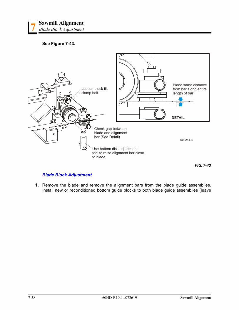
Sawmill AlignmentBlade Block Adjustment7
See Figure 7-43.
Blade Block Adjustment
1. Remove the blade and remove the alignment bars from the blade guide assemblies.Install new or reconditioned bottom guide blocks to both blade guide assemblies (leave
FIG. 7-43
600244-4
Loosen block tiltclamp bolt
Check gap betweenblade and alignmentbar (See Detail)
DETAIL
Blade same distancefrom bar along entirelength of bar
Use bottom disk adjustmenttool to raise alignment bar closeto blade
7-38 60HD-R10doc072619 Sawmill Alignment
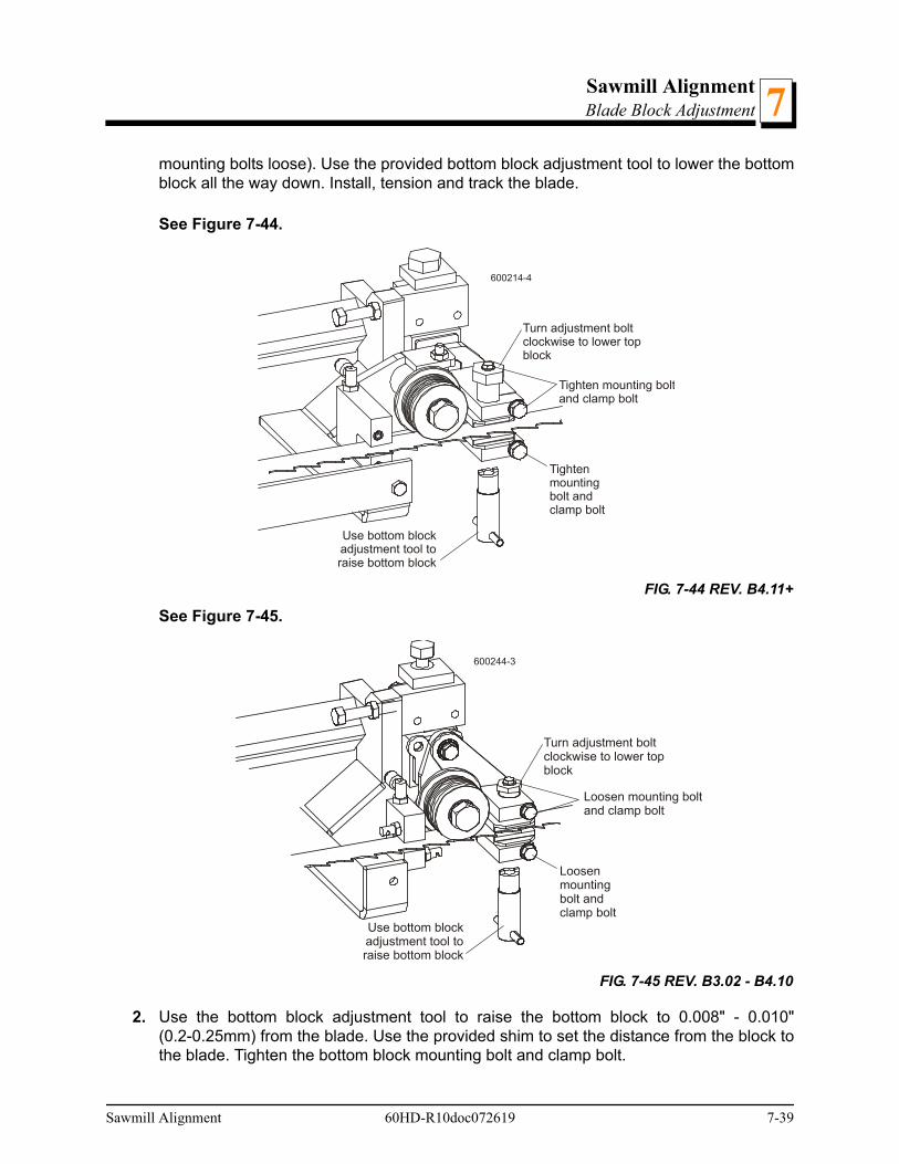
Sawmill AlignmentBlade Block Adjustment 7
mounting bolts loose). Use the provided bottom block adjustment tool to lower the bottomblock all the way down. Install, tension and track the blade.
See Figure 7-44.
See Figure 7-45.
2. Use the bottom block adjustment tool to raise the bottom block to 0.008" - 0.010"(0.2-0.25mm) from the blade. Use the provided shim to set the distance from the block tothe blade. Tighten the bottom block mounting bolt and clamp bolt.
FIG. 7-44 REV. B4.11+
FIG. 7-45 REV. B3.02 - B4.10
Turn adjustment boltclockwise to lower topblock
Tighten mounting boltand clamp bolt
Use bottom blockadjustment tool toraise bottom block
Tightenmountingbolt andclamp bolt
600214-4
600244-3
Turn adjustment boltclockwise to lower topblock
Loosen mounting boltand clamp bolt
Use bottom blockadjustment tool toraise bottom block
Loosenmountingbolt andclamp bolt
Sawmill Alignment 60HD-R10doc072619 7-39
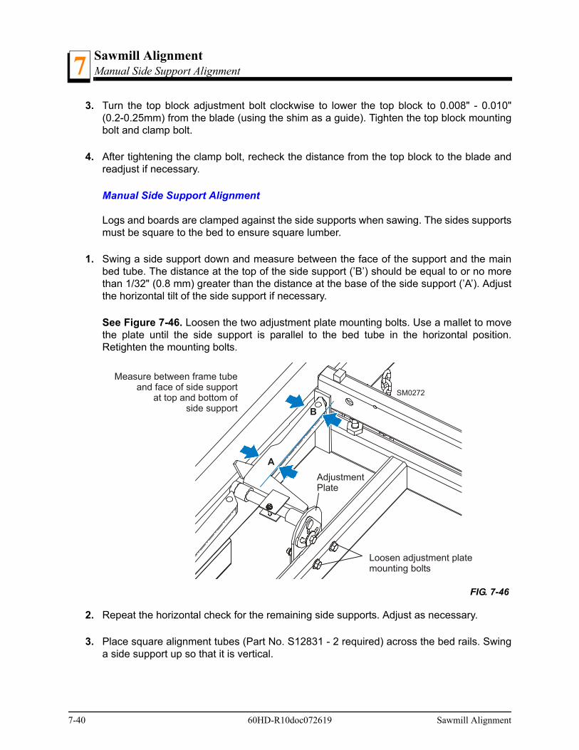
Sawmill AlignmentManual Side Support Alignment7
3. Turn the top block adjustment bolt clockwise to lower the top block to 0.008" - 0.010"(0.2-0.25mm) from the blade (using the shim as a guide). Tighten the top block mountingbolt and clamp bolt.
4. After tightening the clamp bolt, recheck the distance from the top block to the blade andreadjust if necessary.
Manual Side Support Alignment
Logs and boards are clamped against the side supports when sawing. The sides supportsmust be square to the bed to ensure square lumber.
1. Swing a side support down and measure between the face of the support and the mainbed tube. The distance at the top of the side support (’B’) should be equal to or no morethan 1/32" (0.8 mm) greater than the distance at the base of the side support (’A’). Adjustthe horizontal tilt of the side support if necessary.
See Figure 7-46. Loosen the two adjustment plate mounting bolts. Use a mallet to movethe plate until the side support is parallel to the bed tube in the horizontal position.Retighten the mounting bolts.
2. Repeat the horizontal check for the remaining side supports. Adjust as necessary.
3. Place square alignment tubes (Part No. S12831 - 2 required) across the bed rails. Swinga side support up so that it is vertical.
FIG. 7-46
SM0272
Measure between frame tubeand face of side support
at top and bottom ofside support
A
B
Loosen adjustment platemounting bolts
AdjustmentPlate
7-40 60HD-R10doc072619 Sawmill Alignment
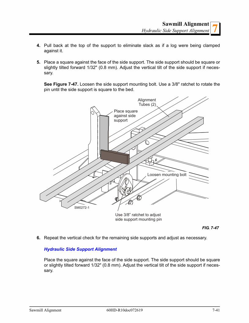
Sawmill AlignmentHydraulic Side Support Alignment 7
4. Pull back at the top of the support to eliminate slack as if a log were being clampedagainst it.
5. Place a square against the face of the side support. The side support should be square orslightly tilted forward 1/32" (0.8 mm). Adjust the vertical tilt of the side support if neces-sary.
See Figure 7-47. Loosen the side support mounting bolt. Use a 3/8" ratchet to rotate thepin until the side support is square to the bed.
6. Repeat the vertical check for the remaining side supports and adjust as necessary.
Hydraulic Side Support Alignment
Place the square against the face of the side support. The side support should be squareor slightly tilted forward 1/32" (0.8 mm). Adjust the vertical tilt of the side support if neces-sary.
FIG. 7-47
SM0272-1
Place squareagainst sidesupport
Loosen mounting bolt
AlignmentTubes (2)
Use 3/8” ratchet to adjustside support mounting pin
Sawmill Alignment 60HD-R10doc072619 7-41

Sawmill AlignmentClamp Stop/Stop Bolt Adjustment7
See Figure 7-48. Loosen the top jam nut. Adjust the two lower jam nuts up to tilt the sidesupport back. Adjust the two lower jam nuts down to tilt the side support forward.Retighten the top jam nut and repeat for the other hydraulic side support.
Clamp Stop/Stop Bolt Adjustment
1. Once the side supports are aligned, pivot them down to their horizontal position.
2. Tie a string to the stop block at the first bed rail. Stretch the string toward the rear of theframe and tie to the stop block at the last bed rail.
FIG. 7-48
600026-1
Place squareagainst sidesupport
AlignmentTubes (2)
Adjust jam nuts upto tilt side support back;Adjust jam nuts downto tilt side support forward
Loosen topjam nut
7-42 60HD-R10doc072619 Sawmill Alignment
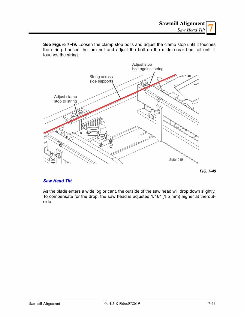
Sawmill AlignmentSaw Head Tilt 7
See Figure 7-49. Loosen the clamp stop bolts and adjust the clamp stop until it touchesthe string. Loosen the jam nut and adjust the bolt on the middle-rear bed rail until ittouches the string.
Saw Head Tilt
As the blade enters a wide log or cant, the outside of the saw head will drop down slightly.To compensate for the drop, the saw head is adjusted 1/16" (1.5 mm) higher at the out-side.
FIG. 7-49
SM0191B
String acrossside supports
Adjust clampstop to string
Adjust stopbolt against string
Sawmill Alignment 60HD-R10doc072619 7-43
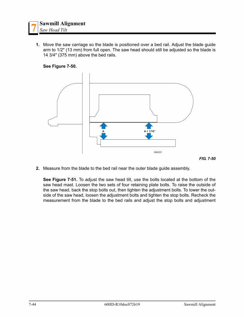
Sawmill AlignmentSaw Head Tilt7
1. Move the saw carriage so the blade is positioned over a bed rail. Adjust the blade guidearm to 1/2" (13 mm) from full open. The saw head should still be adjusted so the blade is14 3/4" (375 mm) above the bed rails.
See Figure 7-50.
2. Measure from the blade to the bed rail near the outer blade guide assembly.
See Figure 7-51. To adjust the saw head tilt, use the bolts located at the bottom of thesaw head mast. Loosen the two sets of four retaining plate bolts. To raise the outside ofthe saw head, back the stop bolts out, then tighten the adjustment bolts. To lower the out-side of the saw head, loosen the adjustment bolts and tighten the stop bolts. Recheck themeasurement from the blade to the bed rails and adjust the stop bolts and adjustment
FIG. 7-50
A A + 1/16”
SM0257
7-44 60HD-R10doc072619 Sawmill Alignment
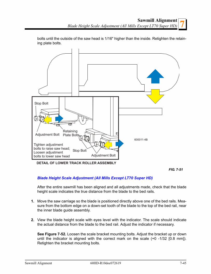
Sawmill AlignmentBlade Height Scale Adjustment (All Mills Except LT70 Super HD) 7
bolts until the outside of the saw head is 1/16" higher than the inside. Retighten the retain-ing plate bolts.
Blade Height Scale Adjustment (All Mills Except LT70 Super HD)
After the entire sawmill has been aligned and all adjustments made, check that the bladeheight scale indicates the true distance from the blade to the bed rails.
1. Move the saw carriage so the blade is positioned directly above one of the bed rails. Mea-sure from the bottom edge on a down-set tooth of the blade to the top of the bed rail, nearthe inner blade guide assembly.
2. View the blade height scale with eyes level with the indicator. The scale should indicatethe actual distance from the blade to the bed rail. Adjust the indicator if necessary.
See Figure 7-52. Loosen the scale bracket mounting bolts. Adjust the bracket up or downuntil the indicator is aligned with the correct mark on the scale (+0 -1/32 [0.8 mm]).Retighten the bracket mounting bolts.
FIG. 7-51
600011-4B
Stop Bolt
DETAIL OF LOWER TRACK ROLLER ASSEMBLY
Stop BoltAdjustment Bolt
Adjustment BoltRetainingPlate Bolts
Tighten adjustmentbolts to raise saw head;Loosen adjustmentbolts to lower saw head
Sawmill Alignment 60HD-R10doc072619 7-45
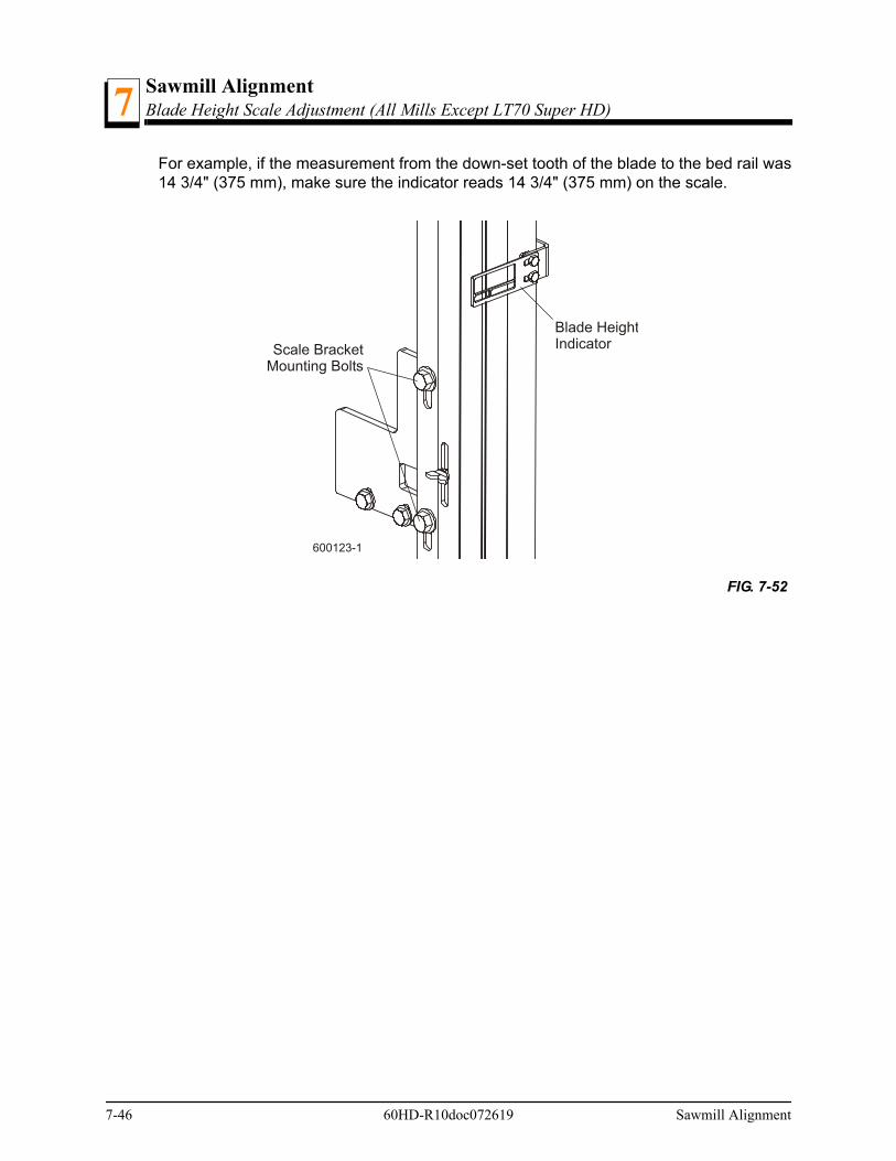
Sawmill AlignmentBlade Height Scale Adjustment (All Mills Except LT70 Super HD)7
For example, if the measurement from the down-set tooth of the blade to the bed rail was14 3/4" (375 mm), make sure the indicator reads 14 3/4" (375 mm) on the scale.
FIG. 7-52
Blade HeightIndicatorScale Bracket
Mounting Bolts
600123-1
7-46 60HD-R10doc072619 Sawmill Alignment
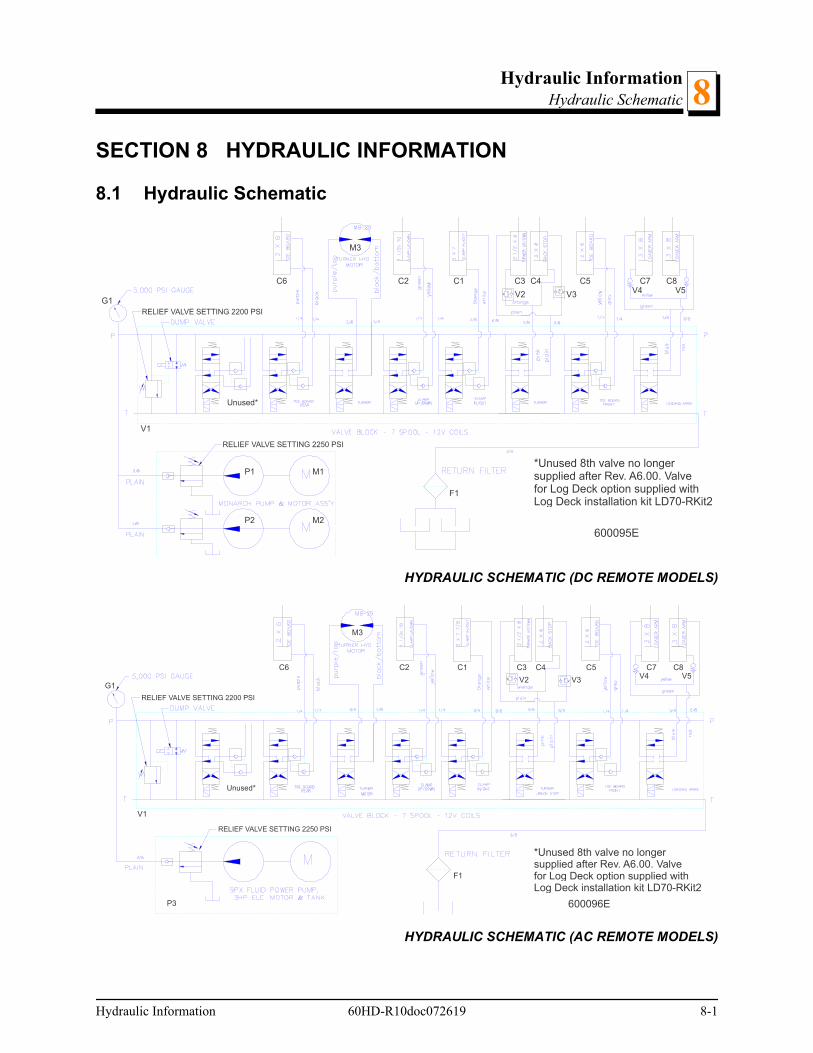
Hydraulic InformationHydraulic Schematic
Hydraulic Information 60HD-R10doc072619 8-1
8
SECTION 8 HYDRAULIC INFORMATION
8.1 Hydraulic Schematic
HYDRAULIC SCHEMATIC (DC REMOTE MODELS)
HYDRAULIC SCHEMATIC (AC REMOTE MODELS)
600095E
C1C2 C3 C5C6 C4 C7 C8
F1
G1
P1
P2
M1
M2
V1
V2 V3 V4 V5
M3
Unused*
RELIEF VALVE SETTING 2200 PSI
*Unused 8th valve no longersupplied after Rev. A6.00. Valvefor Log Deck option supplied withLog Deck installation kit LD70-RKit2
RELIEF VALVE SETTING 2250 PSI
600096E
C1C2 C3 C5C6 C4 C7 C8
F1
G1
P3
M3
V1
V2 V3 V4 V5
Unused*
*Unused 8th valve no longersupplied after Rev. A6.00. Valvefor Log Deck option supplied withLog Deck installation kit LD70-RKit2
RELIEF VALVE SETTING 2200 PSI
RELIEF VALVE SETTING 2250 PSI
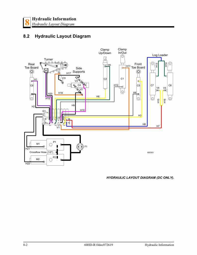
Hydraulic InformationHydraulic Layout Diagram8
8-2 60HD-R10doc072619 Hydraulic Information
8.2 Hydraulic Layout Diagram
HYDRAULIC LAYOUT DIAGRAM (DC ONLY).
C1C2C3
H10
H18
H19
H11
H2
H13
H1
5
H8H7
H5
H6
H12
H4
H3
H9
C4 C5C6 C7 C8
M1P1
G1
F1
M2P2
V2
V3
V4 V5
H1
600303
H17M3
H20
H1
4H
16
H21
H22
V1
ClampIn/Out
ClampUp/Down
Turner
SideSupports
FrontToe Board
RearToe Board
Log Loader
Crossflow Hose (1/2")

Hydraulic InformationHydraulic Components
Hydraulic Information 60HD-R10doc072619 8-3
88.3 Hydraulic Components
ID Wood-Mizer Part.#
Description
C1 017275 Hyd. Cylinder, 3" Bore X 7" Stroke
C2 015050 Hyd. Cylinder, 1 1/2" Bore X 10" Stroke
C3 034267 Hyd. Cylinder, 2” Bore x 10” Stroke
C4 034736 Hyd. Cylinder, 2 1/2" Bore X 6" Stroke
C5, C6 014482 Hyd. Cylinder, 1 1/2” Bore x 6” Stroke
C7, C8 042754 Hyd. Cylinder, 3" Bore X 8" Stroke
F1 P20301 Filter, Hydraulic Fluid Cartridge
G1 P10052 Gauge, 5000 PSI Hydraulic
P1, P2 P12701 Hydraulic Pump, With Motor (DC)
P3 054824 Hyd. Pump/Tank/Motor (230/460 AC)
034794 Hydraulic Pump/Tank/Motor (575VAC)
V1 025688 1
1 Valve 025688 replaces Valve 036730 (Progressive Power #BKAA0168X0405) supplied prior to Rev. B4.02. Use component parts to service or re-place with Valve 025688.
Valve, 7-Section Hydraulic Expndbl.
V2, V3 015484 Sequence Valve, 700 psi
V4, V5 038734 Valve, Hydraulic 6.5GPM Velocity Fuse
M1, M2 052807 Motor, Iskra Hydraulic Pump (DC)
M3 007331 Motor, Hydraulic Log Turner Chain

Hydraulic InformationHydraulic Hoses8
8-4 60HD-R10doc072619 Hydraulic Information
8.4 Hydraulic Hoses
ID Color Code
LENGTH "A"
Application HOSE PART #
H1 Purple 81” 1/4” Rear Toe Board Top 048306
H2 Black 87” 1/4” Rear Toe Board Base 048307
H3 Yellow 52” 1/4” Front Toe Board Top 048308
H4 Gray 56” 1/4” Front Toe Board Base 048309
H5 Green 43” 1/4” Clamp Up/Down Top 048310
H6 Yellow 32” 1/4” Clamp Up/Down Base 048311
H7 Red 22” 3/8” Loading Arm Base 048312
H8 Blue 22” 3/8” Loading Arm Top 048312
H9 Plain 16” 3/8” Side Support Base 048313
H10 Pink 15” 3/8” Side Support Top 048314
H11 Orange 20” 3/8” Clamp In/Out Base 048315
H12 White 23” 3/8” Clamp In/Out Top 048316
H13 Green 74” 3/8” Loading Arm Branch Top 048317
H14 Green 34” 3/8” Loading Arm Branch Top 048318
H15 Yellow 77” 3/8” Loading Arm Branch Base 048298
H16 Yellow 34” 3/8” Loading Arm Branch Base 048318
H17 Plain 73” 3/8” Log Turner Base 048319
H18 Orange 65” 3/8” Log Turner Top 048320
H19 Purple 61” 3/8” Log Turner Motor (Nearest Frame) 006725
H20 Black 65” 3/8” Log Turner Motor (Furthest from Frame)
006726
H21 Plain 27” 1/4” Pump to Valve 036293
H22 Plain 38” 1/4” Pump to Valve 036294

INDEX
A
alignmentlower track rollers 7-21main bed rails 7-24slide pad adjustment 7-21
autoclutch optionoperation 4-8
B
batterytroubleshooting problems 6-4
bladebreakage, troubleshooting 6-1installation 3-19tensioning 3-21tracking 3-26
blade guide armoperation 4-7
C
chainfeed tension 5-26maintenance 5-9up/down tension 5-21
clamping logs 4-5
H
hydrauliccomponent list 8-3control operation 4-1, 4-4fluid level 5-19hose list 8-4layout diagram 8-2schematic 8-1troubleshooting problems 6-12
L
leveling logs 4-5
loading logs 4-4
M
maintenanceautoclutch belt (DC only) 5-18blade guide 5-2blade tensioner 5-10blade wheel belts 5-13carriage track/wipers 5-5drive belt 5-14drum switches 5-8hydraulic system 5-19mast rails 5-6, 5-7miscellaneous 5-9part wear life 5-1power feed 5-26remote cable chain 5-30sawdust removal 5-4up/down 5-21
O
operationedging 4-12sawing 4-11
P
power feedmechanical troubleshooting test 6-11operation 4-10speed adjustment 4-9troubleshooting problems 6-8
Index 60HD-R10doc072619 i

S
safetysymbols 2-1
scaleblade height operation 4-14inch height 4-14quarter inch 4-15
service informationbranch locations 1-3customer & sawmill ID 1-5general contact info 1-2
setupportable sawmill 3-10stationary sawmill 3-1
switchpower feed & up/down maintenance 5-8
T
tensionermaintenance 5-12
troubleshooting 6-1electrical problems 6-3hydraulic problems 6-12power feed problems 6-8sawing problems 6-1
turning logs 4-5
U
up/downoperation 4-6troubleshooting problems 6-3
W
water lubeoperation 4-16
ii 60HD-R10doc072619 Index