Embed Size (px)
Citation preview
1
Powered Stair Climbing Hand Truck
Operator’s Manual
Magline, Inc.
503 South Mercer Street Pinconning, MI 48650
Tel: 800-MAGLINE (624-5463)
Fax: 989-879-5399 Web: www.magliner.com
E-mail: [email protected]
2
Contents
1 INSTALLATION OF NOSE..........................................................................3
2 INTRODUCTION..........................................................................................3 2.1 General Safety Instructions..................................................................................................... 3 2.2 Before Using Your Liftkar ....................................................................................................... 3 2.3 Specifications of Liftkar Models.............................................................................................. 4 2.4 Specifications of Liftkar Battery.............................................................................................. 4
3 CONTROLS .................................................................................................5 3.1 Model ..................................................................................................................................... 5 3.2 Safety Flap............................................................................................................................. 5 3.3 Main Switch............................................................................................................................ 6 3.4 Control Box ............................................................................................................................ 6 3.5 Round up Switch..................................................................................................................... 7
4 BATTERY ....................................................................................................7 4.1 Installing the Battery ............................................................................................................... 7 4.2 Removing the Battery ............................................................................................................. 7
5 CHARGING THE BATTERY........................................................................7 5.1 Battery Chargers..................................................................................................................... 8
6 OPERATION ................................................................................................9 6.1 Descending Stairs ................................................................................................................ 10 6.2 Important Operator Information............................................................................................ 11
7 WARRANTY AND LIABILITY....................................................................13 7.1 Warranty ............................................................................................................................... 13 7.2 Liability .................................................................................................................................. 14

3
1 Installation of Nose To install the nose, place the Liftkar on its back-side. Locate the three bolts included in packaging and secure the nose to the fixed nose plate mounting bracket with a T-40 Torx wrench. The longer bolt goes in the middle.
2 Introduction Weighing only 35 pounds, the Liftkar efficiently climbs at a rate of up to 48 steps per minute. With capacities up to 375 pounds, we promise the Liftkar will be faster than you are! The heavy duty battery handles 220 steps at full load and over 300 steps with a half load on a single charge. The Liftkar is able to go up and down stairs depending on your delivery demands. Many options are available to customize your Liftkar to meet your specific needs. Several noses, various handles, and puncture proof tires are a few of the options offered.
The Liftkar has a mechanical clutch that prevents damage if the unit is used to descend stairs with the controls in the ascend position. The Liftkar features electronic overload protection preventing operation with a load over the weight limit. The Liftkar has a slow and fast ascending speed and one descending speed.
2.1 General Safety Instructions Always make sure no one is beneath the Liftkar on the stairs Always secure the load with the appropriate accessories Always wear skid-proof, steel-toed shoes Never reach anything into the lifting mechanism when the battery is inserted Always remove the battery when unit is not in use, during transit, and prior to
any maintenance procedures to prevent accidental operation. Always use a Magliner Liftkar Battery Charger to charge your Liftkar battery
2.2 Before Using Your Liftkar Read the entire Operator’s Manual Fully charge battery Install nose following directions above Familiarize yourself with Liftkar controls and buttons Install fully charged battery Practice using your Liftkar on a stairway with no load at first, then with
approximately 60 pounds

4
2.3 Specifications of Liftkar Models
Specifications 170 Ergo 140 Ergo
140 Ergo BW 140 Uni 110 Fold
Capacity 375 lbs. 300 lbs. 300 lbs. 240 lbs.
Maximum speed (steps/minute) 29 35 35 48
Weight without battery 35 lbs. 35 lbs. 35 lbs. 35 lbs.
Maximum step height 8” 8” 8” 8”
Overall height 62“ 62” 58” 38 ½ “ folded
60” unfolded
Width 19 “ 19 “ 19 “ 19 “
Depth 18” to 24”
Depends on nose18” to 24”
Depends on nose18” to 24”
Depends on nose 18” to 24”
Folded
2.4 Specifications of Liftkar Battery
Liftkar Battery
Fuse Internal blowout fuse (30 amps)
Plug Socket for charger DC Jack 2.1 x 9.5
Weight 9 Pounds
Capacity 5 Ah
Voltage 24 VDC (2 x 12 VDC – 5 Ah)
Battery Cells Sealed lead- acid maintenance-free and approved for air travel by DOT and IATA

5
3 Controls
3.1 Model
Red Handle Grips and O-Rings
Swing arm
Red Handle
Upper crossbar
Small Gray Wheels
Nose plate
Wheel guard
Round-up switch Control box
3.2 Safety Flap
It may be necessary to use your foot to assist in tilting back your loaded Liftkar. To do this, use the swing arm, a main wheel, or the lower portion of the drive unit. The safety flap prevents your foot from getting jammed under the swing arm by automatically ceasing all Liftkar operation when depressed. To resume use if this occurs, release safety flap and press the round up switch.

6
Caution !
! Only turn main battery switch on after tilting the load.
3.3 Main Switch
The main switch is located on the battery cover and is used to turn the power supply on and off (see section 3.1 Model).
Power can be shut off by doing one of the following:
Turning the main switch on the battery unit
Removing the battery
Pressing the ascend / descend button for 3 seconds or longer
Automatically after 10 minutes of non-use
3.4 Control Box
Speed Switch
• When in ascend mode, use the speed switch to select high (2 lines) or low (1 line) speed.
• Low speed is advisable for training, heavy loads, and awkward locations.
• In descend mode the speed is permanently set (see section 4 Operation).
Ascend / Descend Button Briefly press the button to
switch the Liftkar to ascend mode or descend mode.
The Liftkar will switch off if the button is pressed for more than 3 seconds.
Indicator Light Constant green means the Liftkar is in ascend mode and the round up
switch in the handle bar is active. The lifting mechanism operates when the round up switch is depressed and stops when released.
Flashing green means the Liftkar is in descend mode and the round up switch is inactive.
Constant red means the Liftkar is in descend mode and the support wheels move quickly to the descend position.
Flashing red means the Liftkar is overloaded and the indicator light will flash for 3 seconds and shut off.

7
3.5 Round up Switch
The round up switch (see page 5) is active only in the ascend mode and turns the lifting mechanism on and off. The swing arm assembly will begin to rotate when the round up switch is depressed.
4 Battery Caution !
! Always remove the battery when Liftkar is not in use and when performing any maintenance procedures. Improper installation and removal of battery will cause premature wear of battery case and cause battery to fall out during use.
4.1 Installing the Battery (1) Locate corner "A" on both sides of battery and slide into hook "B" on the
inner part of the frame (2) Snap battery forward to engage locking hooks
4.2 Removing the Battery Pull battery upward to unlock. Battery must be lifted vertically to disengage locking hook. Failure to lift vertically will wear locking clips and will lead to battery falling out during operation. Do not hinge back. Lift straight up to clear the locking hooks.
5 Charging the Battery The battery cells within the battery housing are maintenance-free, sealed, and rechargeable. Their durability largely depends on the charge and discharge cycles. It is possible to extract far more than 1,000 partial discharges from lead-acid batteries if total discharge is avoided.
Always charge battery immediately after use Fully charge battery before first use
Always keep battery as fully charged as possible and avoid total discharge

8
Lead-acid batteries will self-discharge when not used
The battery automatically has a 4.5 hour cut-out time, so overcharging is impossible
The optimum temperature for charging the battery is 65°–75° Fahrenheit (18° to 24° Celsius). Temperatures outside this range may reduce battery capacity
If the battery has not been fully charged or tends to lose charge too rapidly, this will reduce the speed and capacity of the Liftkar and it may go into the overload mode as a result, even with light loads
Caution !
! Do not leave the battery completely discharged or half charged. Keep fully charges at all times
5.1 Battery Chargers There are two optional DC chargers and one AC charger available from Magline for your Liftkar. The AC charger is included with each new Liftkar purchase. Prior to every use, check your battery charger for any damaged wires.
Battery Holder with AC Charger (part number 930602) This charger comes standard with every Liftkar purchase.
High performance is achieved by 2-step automatic and digital control engineering. This allows for quick charging in the first step and compensation / trickle charging in the second step.
To test the battery, connect the battery charger to the battery (without plugging into the wall outlet). After approximately 9 seconds the test result will display by progress bars:
100% - full Battery is operational
80 %
50%
20% Charge the battery
0% - flat To charge the battery with this type of charger: 1. Connect the charging unit to the battery 2. Turn battery on by the main switch on the battery 3. Plug the charging unit into the AC type wall outlet 4. The charging operation begins

9
Compensation / Trickle Charging Once the battery is fully charged, the charging unit switches over to compensation/ trickle charge. On the display, the battery symbol is shown with 4 bars and remains solid. If charging does not begin, there are two possible reasons:
Display: and symbols blink alternately indicating polarity reversal. Correct polarity by ensuring the battery wire (part number 004126) is plugged into a positive and a negative socket on each battery cell. This wire should not be plugged into two negative sockets. Also, ensure the other wire (part number 004129) is plugged into a negative and positive socket. For additional help, see Battery schematic in the back of your Maintenance Manual.
Display: and symbols blink alternately indicating a break in connection to battery. Check charging clips, cables, contacts, battery pole terminals etc.
Optional DC Battery Charger less mounting plate (part number 930600)
This type of charger is optional and enables charging the battery in your vehicle while leaving the battery conveniently inserted in your Liftkar. The green light by itself indicates the power is on. The other three lights indicate the level of charge:
Green- battery is fully charged, but is still being trickle charged to compensate for the internal loss of capacity when battery is not in use.
Yellow- battery is 70-80% charged and is trickle charging.
Red- battery is discharged and is charging fast. Optional DC Battery Charger with mounting plate (part number 930114)
This type of charger is optional. To charge, the battery must be removed from the Liftkar and properly positioned on the mounting plate. The green light by itself indicates the power is on. The other three lights indicate the level of charge:
Green- battery is fully charged, but is still being trickle charged to compensate for the internal loss of capacity when battery is not in use.
Yellow- battery is 70-80% charged and is trickle charging
Red- battery is discharged and is charging fast
6 Operation
Control Box (see section 3.4) Round up switch

10
6.1 Descending Stairs
Press ascend / descend button briefly until the indicator light shines green continuously (see section 3.4 Control Box). The Liftkar is now in the ascend mode. Select high or low speed.
Pressing the round up switch in the upper handle operates the support wheels and will lift the Liftkar over the step continuing until the button is released. As the main wheels rest on the stair, immediately pull the Liftkar back to touch the rise of the next step up.
Caution !
! Holding the Liftkar too flat on stairs with open risers can result in partially trapping the support wheels under the stair. This may cause excessive pressure on the drive unit and cause unit to go into overload mode and shut down. To resume use, press the ascend / descend button to reset.
Press ascend / descend button briefly again until the indicator light flashes green. The Liftkar is now in the descend mode and the support wheels will move to the descend position automatically. The round up switch is now non-functional.
With the support wheels in the descend position, the Liftkar can be rolled over the step and the support wheels will lower the Liftkar onto the next step down. When the main wheels land on the lower step, the support wheels automatically rotate to the descend position for the descent onto the next step, all within approximately half a second.
During the descent, the indicator light changes to constant red. After reaching the descend position, the indicator light changes back to flashing green.

11
Caution !
! As soon as the Liftkar rolls off the step, be sure the main wheels are kept against the rise until the support wheels reach the descend position.
Just before the swing arm reaches the descending position, the support wheels reach the upper edge of the stair and lift the Liftkar approximately half an inch.
In the case of closed risers with low steps the support wheels may touch the stair riser and the Liftkar could move approximately 3 to 4 inches forward. This is normal as the Liftkar prepares to advance to the next step.
It is unnecessary to press the round up switch to descend the stairs. The support wheels operate automatically at a set speed.
6.2 Important Operator Information
When ascending, the balance of the load changes as soon as the support wheels start lifting the load. Care should be taken at the point where the support wheels take the load during ascent. There is a forward movement of the Liftkar. This is easily compensated by tilting the handle backwards. To eliminate any major forward movements, lower the Liftkar backwards about 15° before the support wheels begin to lift. Do not overload the Liftkar. Exceeding the load capacity activates the overload mode causing the Liftkar to stop and lower the main wheels slowly to the lower step. The indicator light flashes red for about 3 seconds after which the ascend / descend button will need to be reset.
Caution !
! Once the battery is discharged, the unit goes into overload even with loads below the specified capacity.
12
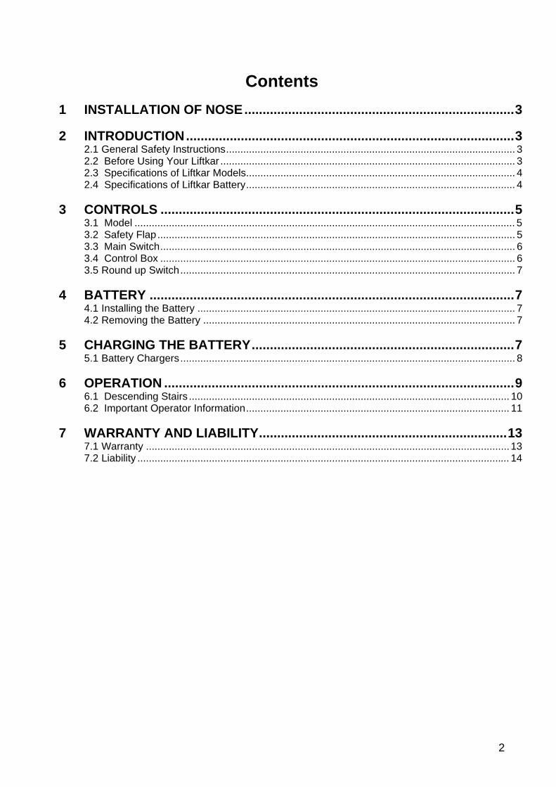
Never throw loads onto the Liftkar. The impact of throwing loads onto the Liftkar could result in fracturing the drive unit. If necessary to load the Liftkar in a horizontal position be sure the support wheels are raised between the main wheels and carefully place the item on the Liftkar.
WRONG RIGHT During normal operations, the battery is held securely in place by locking hooks. A strong, vertical pull is required to remove it. Moving backwards very quickly and striking a high step or similar equipment abuse could result in the battery ejecting from its location. If this happens, the Liftkar will cease operation. Failure to negotiate steps "square-on" will damage the underside of the drive unit.
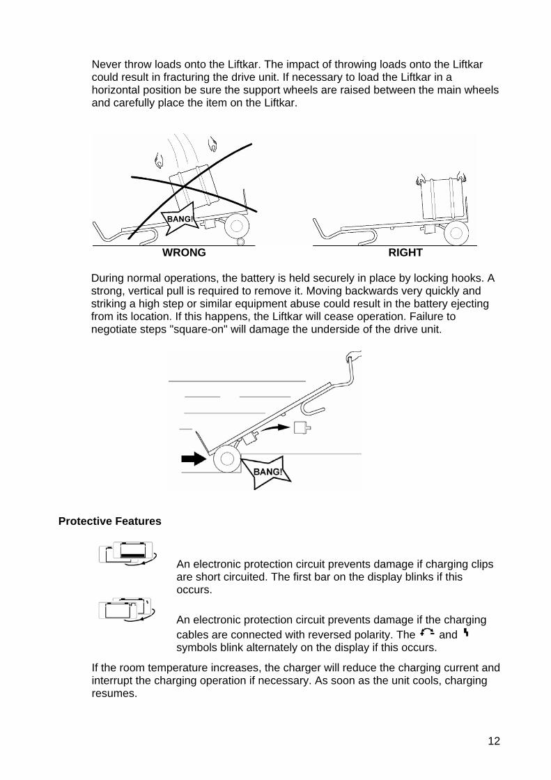
Protective Features
An electronic protection circuit prevents damage if charging clips are short circuited. The first bar on the display blinks if this occurs.
An electronic protection circuit prevents damage if the charging cables are connected with reversed polarity. The and symbols blink alternately on the display if this occurs.
If the room temperature increases, the charger will reduce the charging current and
interrupt the charging operation if necessary. As soon as the unit cools, charging resumes.

13
If the battery fails to reach a certain voltage value within a pre- determined time, the charger will automatically cut out.
After automatic cut out
1. Unplug the charger from the AC wall outlet 2. Disconnect the charger from the battery 3. Investigate the reason for the safety cut out
Technical Data
• Main voltage (50/60 Hz, +/- 15%) 100-230 V AC • Charging voltage 24 V DC • Time until safety cut-out 4.5 hours The charger has been function tested in a temperature range from –4° to 122° Fahrenheit (-20° to 50° Celsius) and in atmospheric humidity ranging from 5% to 85%.
Safety Rules Use Liftkar battery chargers for intended purpose only. These battery chargers are designed to charge lead storage batteries filled with liquid gel and AGM (absorbed glass mat) electrolytes only. Liftkar battery charger should never be used to charge NiCd and NiMH batteries and primary cells. Only use the charging unit if protected from direct sunlight and moisture.
CE Marking All Liftkar battery chargers meet the fundamental requirements of the Low-Voltage and Electromagnetic Compatibility Directive and is thus CE-marked.
7 Warranty and Liability
7.1 Warranty
The warranty period for the Liftkar is 12 months (6 months for batteries) from the date of purchase and covers defective material and production faults. Exclusions in the warranty are:
Normal wear and tear on parts Damage resulting from abnormal load Damage due to the excessive exertion of force Modifications to the Liftkar, accessories, or parts

14
7.2 Liability
SANO Transportgeräete GmbH as manufacturer and Magline, Inc. as distributor are not responsible for the safety of the Liftkar if:
The Liftkar is used for purposes other than those for which it is intended The Liftkar is not regularly maintained properly by a mechanical workshop The instructions in this Operator’s Manual are not observed Non-Liftkar parts are installed or connected to the Liftkar Original parts are removed
Design Protection by Patents
The lifting system of the SAL series is protected by international patent applications for Europe, USA and Japan. The modular structure of the basic frame is also protected by a patent application. A patent is pending for the FOLD model rotary joint.
LIFTKAR® is a registered trademark of SANO Transportgeraete GmbH.
Copyright 2005 Magline, Inc. B8078