Embed Size (px)
Citation preview

*ARMY TM 9-6115-644-10AIR FORCE TO 35C2-3-446-11
MARINE CORPS TM 09249A/09246A-10/1
TECHNICAL MANUAL
OPERATOR’S MANUAL
GENERATOR SET,
SKID MOUNTED, TACTICAL QUIET
30 KW, 50/60 AND 400 HZ
MEP-805A (50/60 HZ) 6115-01-274-7389
MEP-815A (400 HZ) 6115-01-274-7394
*This manual supersedes TM 9-6115-644-10 dated 15 January 1993.
DISTRIBUTION STATEMENT A: Approved for public release; distribution is unlimited
HEADQUARTERS, DEPARTMENTS OF THE ARMY,AIR FORCE AND HEADQUARTERS U.S. MARINE CORPS
30 JULY 1993


CHANGE
NO. 2
ARMY TM 9-6115-644-10AIR FORCE TO 35C2-3-446-11
MARINE CORPS TM 09249A/09246A-10/1C2
HEADQUARTERS, DEPARTMENTS OFTHE ARMY, AIR FORCE AND
HEADQUARTERS, U.S. MARINE CORPSWASHINGTON, D.C., 30 October 1996
Operator’s Manual
GENERATOR SET, SKID MOUNTED, TACTICAL QUIET30 KW, 50/60 AND 400 HZ
MEP-805A (50/6OHZ) 6115-01-274-7389MEP-815A (400HZ) 6115-01-274-7394
DISTRIBUTION STATEMENT A: Approved for public release; distribution is unlimited
TM 9-6115-644-10/TO 35C2-3-446-11 /TM 09249A/09246A-10/1, 30 July 1993, is changed as follows:
1. Remove and insert pages as indicated below. New or changed text material is indicated by a vertical barin the margin. An illustration change is indicated by a miniature pointing hand.
Remove pagesi through iv1-7 and 1-8
2-5 through 2-102-15 and 2-164-31 and 2-32-----
2-33 and 2-342-39 and 2-403-9 and 3-10
Insert pagesi through iv1-7 and 1-82-5 through 2-102-15 and 2-162-31 and 2-322-32.1/(2-32.2 blank)2-33 and 2-342-39/(2-40 blank)3-9 and 3-10
2. Retain this sheet in front of manual for reference purposes.

ARMY TM 9-6115-644-10AIR FORCE TO 35C2-3446-11MARINE CORPS TM 09249A/O9246A-10/1
By Order of the Secretaries of the Army, Air Force, and Navy (Including the Marine Corps):
Official:DENNIS J. REIMER
General, United States ArmyChief of Staff
Administrative Assistant to theSecretary of the Army
02946
RONALD R. FOGELMANGeneral, USAFChief of Staff
HENRY VICCELLIO, JR.General, USAFCommander, Air Force Materiel Command
J. E. BUFFINGTONRear Admiral, CEC, US NavyCommanderNavy Facilities EngineeringCommand
D. R. BLOOMERColonel, USMCDirector, Program SupportMarine Corps Systems Command
DISTRIBUTION:To be distributed in accordance with DA Form 12-25-E, block no. 5241, requirements for
TM 9-6115-641-10.

C1
CHANGE
NO. 1
ARMY TM 9-115-644-10AIR FORCE TO 35C2-3-446-11
MARINE CORPS TM 09249A/09246A-10/1
HEADQUARTERS, DEPARTMENTS OFTHE ARMY AND THE AIR FORCE, ANDHEADQUARTERS, U.S. MARINE CORPS
WASHINGTON, D.C., 31 May 1995
Operator’s Manual
GENERATOR SET,SKID MOUNTED, TACTICAL QUIET
30 KW, 50/60 AND 400 HZMEP-805A (50/60 HZ) 6115-01-274-7389MEP-815A (400 HZ) 6115-01-274-7394
DISTRIBUTION STATEMENT A: Approved for public release; distribution is unlimited
TM 9-6115-644-10/TO 35C2-3-446-11/TM 09249A/09246A-10/1, 30 July 1993, is changed as follows:
1. Remove and insert pages as indicated below. New or changed text material is indicated by a vertical barin the margin. An illustration change is indicated by a miniature pointing hand.
Remove pages Insert pages
1-11 through 1-14 1-11 through 1-14
2-9 through 2-40 2-9 through 2-39/(2-40 blank)
3-3 and 3-4 3-3 and 3-4
3-7 and 3-8 3-7 and 3-8
2. Retain this sheet in front of manual for reference purposes.

ARMY TM 9-6115-644-10AIR FORCE TO 35C2-3-446-11MARINE CORPS TM 09249A/09246A-10/1
C1
By Order of the Secretaries of the Army, Air Force, and Navy (Including the Marine Corps):
Official:
GORDON R. SULLIVANGeneral, United States Army
Chief of Staff
Acting Administrative Assistant to theSecretary of the Army
00233
JOEL B HUDSON
RONALD R. FOGELMANGeneral, USAFChief of Staff
RONALD W. YATESGeneral, USAFCommander, Air Force Materiel Command
JACK E. BUFFINGTONRear Admiral, CEC, US NavyCommanderNavy Facilities EngineeringCommand
D. R. BLOOMERColonel, USMCDirector, Program SupportMarine Corps Systems Command
DISTRIBUTION:To be distributed in accordance with DA Form 12-25-E, block no. 5267, requirements for
TM 9-6115-644-10.

ARMY TM 9-6115-644-10AIR FORCE TO 35C2-3-446-11
MARINE CORPS TM 09249A/09246A-10/1
WARNING
H i g h v o l t a g e i s p r o d u c e d w h e n t h i s g e n e r a t o r s e t i s i n o p e r a t i o n .I m p r o p e r o p e r a t i o n c o u l d r e s u l t i n p e r s o n a l i n j u r y o r d e a t h .
WARNING
N e v e r a t t e m p t t o s t a r t t h e g e n e r a t o r s e t i f i t i s n o t p r o p e r l yg r o u n d e d . F a i l u r e t o o b s e r v e t h i s w a r n i n g c o u l d r e s u l t i n s e r i o u si n j u r y o r d e a t h b y e l e c t r o c u t i o n .
WARNING
N e v e r a t t e m p t t o c o n n e c t o r d i s c o n n e c t l o a d c a b l e s w h i l e t h e g e n e r a t o ri s r u n n i n g . F a i l u r e t o o b s e r v e t h i s w a r n i n g c o u l d r e s u l t i n s e v e r ep e r s o n a l i n j u r y o r d e a t h b y e l e c t r o c u t i o n .
WARNING
D C v o l t a g e s a r e p r e s e n t a t g e n e r a t o r s e t e l e c t r i c a l c o m p o n e n t s e v e nw i t h g e n e r a t o r s e t s h u t d o w n . A v o i d g r o u n d i n g y o u r s e l f w h e n t o u c h i n ga n y e l e c t r i c a l c o m p o n e n t s . F a i l u r e t o o b s e r v e t h i s w a r n i n g c a n r e s u l ti n p e r s o n a l i n j u r y .
a

ARMY TM 9-6115-644-10AIR FORCE TO 35C2-3-446-11MARINE CORPS TM 09249A/09246A-10/1
WARNING
Bat te ry ac id can cause burns to unpro tec ted sk in .
WARNING
T h e f u e l s i n t h i s g e n e r a t o r s e t a r e h i g h l y e x p l o s i v e . D O N O T s m o k e o ru s e o p e n f l a m e w h e n p e r f o r m i n g m a i n t e n a n c e F l a m e s a n d e x p l o s i o n c a n .o c c u r r e s u l t i n g i n s e v e r e p e r s o n a l i n j u r y o r d e a t h .
WARNING
D O N O T r e f u e l t h e g e n e r a t o r s e t w h i l e i t i s o p e r a t i n g . H o t r e f u e l i n go f t h e g e n e r a t o r s e t w h i l e i n o p e r a t i o n p r e s e n t s a s a f e t y h a z a r d a n ds h o u l d n o t b e a t t e m p t e d H o t e n g i n e s u r f a c e s a n d s p a r k s p r o d u c e d f r o m .t h e e n g i n e a n d g e n e r a t o r c i r c u i t r y a r e p o s s i b l e s o u r c e s o f i g n i t i o n .F l a m e s a n d e x p l o s i o n c a n o c c u r r e s u l t i n g i n s e v e r e p e r s o n a l i n j u r y o rd e a t h .
WARNING
B a t t e r i e s g i v e o f f f l a m m a b l e g a s . D o n o t s m o k e o r u s e o p e n f l a m e w h e np e r f o r m i n g m a i n t e n a n c e . F l a m e s a n d e x p l o s i o n c o u l d r e s u l t i n p e r s o n a li n j u r y o r d e a t h .
b

A R M Y T M 9 - 6 1 1 5 - 6 4 4 - 1 0A I R F O R C E T O 3 5 C 2 - 3 - 4 4 6 - 1 1
MARINE CORPS TM 09249A/09246A-10 /1
WARNING
E x h a u s t d i s c h a r g e c o n t a i n s d e a d l y g a s e s . D o n o t o p e r a t e g e n e r a t o r s e ti n e n c l o s e d a r e a u n l e s s e x h a u s t d i s c h a r g e i s p r o p e r l y v e n t e d o u t s i d e .S e v e r e p e r s o n a l i n j u r y o r d e a t h d u e t o c a r b o n m o n o x i d e p o i s o n i n g c o u l dresult.
WARNING
D o n o t m a n u a l l y d i s c h a r g e o r d e l i b e r a t e l y i n h a l e e t h e r . B r e a t h i n ge t h e r f u m e s c a n c a u s e f a i n t i n g .
WARNING
L i q u i d s u n d e r p r e s s u r e a r e g e n e r a t e d a s a r e s u l t o f o p e r a t i o n o f t h eg e n e r a t o r s e t . H i g h p r e s s u r e l e a k s c o u l d c a u s e s e v e r e p e r s o n a l i n j u r yo r d e a t h .
WARNING
W i t h a n y a c c e s s d o o r o p e n , t h e n o i s e l e v e l o f t h i s g e n e r a t o r s e t w h e no p e r a t i n g c o u l d c a u s e h e a r i n g d a m a g e . H e a r i n g p r o t e c t i o n m u s t b e w o r nw h e n w o r k i n g n e a r t h e g e n e r a t o r s e t w h i l e r u n n i n g .
c

A R M Y T M 9 - 6 1 1 5 - 6 4 4 - 1 0A I R F O R C E T O 3 5 C 2 - 3 - 4 4 6 - 1 1MARINE CORPS TM 09249A/09246A-10 /1
WARNING
C o o l i n g s y s t e m o p e r a t e s a t h i g h t e m p e r a t u r e s . P e r s o n a l i n j u r y o rd e a t h f r o m b u r n s o r s c a l d i n g c a n r e s u l t f r o m c o n t a c t w i t h h i g hp r e s s u r e s t e a m a n d / o r l i q u i d .
WARNING
A v o i d c o n t a c t i n g m e t a l i t e m s w i t h b a r e s k i n i n e x t r e m e c o l d w e a t h e r .F a i l u r e t o o b s e r v e t h i s w a r n i n g c a n r e s u l t i n p e r s o n a l i n j u r y .
d

TECHNICAL MANUAL
NO. 9-6115-644-10
Operator’s Manual
*ARMY TM 9-6115-644-10AIR FORCE TO 35C2-3-446-11
MARINE CORPS TM 09249A/09246A-10/1
HEADQUARTERS, DEPARTMENTS OFTHE ARMY. AIR FORCE AND
HEADQUARTERS, U.S. MARINE CORPSWASHINGTON, D.C. 30 July 1993
GENERATOR SET, SKID MOUNTED, TACTICAL QUIET30 KW, 50/60 AND 400 HZ
MEP-805A (50/60 HZ) 6115-01-274-7389MEP-815A (400 HZ) 6115-01-274-7394
Distribution Statement A: Approved for public release; distribution is unlimited.
REPORTING OF ERRORS AND RECOMMENDING IMPROVEMENTS
You can help improve this manual. If you find any mistakes or if you know of a way to improve theprocedures, please let us know.
(A): Army - Mail your letter or DA Form 2028 (Recommended Changes to Publications and Blank Forms),or DA Form 2028-2 located in the back of this manual directly to: Commander, US Army Aviation and TroopCommand, ATTN: AMSAT-I-MP, 4300 Goodfellow Blvd., St. Louis, MO 63120-1798. You may also submityour recommended changes by E-mail directly to <mpmt%[email protected]>. Instructions forsending an electronic 2028 may be found at the back of this publication immediately preceding the hard copy2028.
(F): Air Force - AFTO Form 22 directly to: Commander, Sacramento Air Logistics Center, ATTN: TILBA,McClellan AFB. CA 95652-5990.
(M): Marine Corps - NVMC Form 10772 directly to: Commander, Marine Corps Logistics Bases (Code 850),Albany, GA 310\704-5000.
A reply will be furnished directly to you
* This manual supersedes TM 9-6115-644-10 dated 15 January 1993.
Change 2 i

ARMY TM 9-6115-644-10AIR FORCE TO 35C2-3-446-11MARINE CORPS TM 09249A/09246A-10/1
CHAPTER 1
SectionSectionSection
CHAPTER 2
Section
Section
SectionSection
CHAPTER 3
SectionSection
Section
IIIIII
I
II
IIIIV
III
III
APPENDIX A.APPENDIX B.
APPENDIX C.APPENDIX D.
TABLE OF CONTENTS
HOW TO USE THIS MANUAL . . . . . .
INTRODUCTION . . . . . . . . . . .
General Information . . . . . . .Equipment Description .Technical Principles of
. . . . .Operation
OPERATING INSTRUCTIONS. . . . . .
Description and Use of Operator'sControls and Indicators . . . .
Preventive Maintenance Checks andServices (PMCS) . . . . . . . .
Operation Under Usual Conditions .Operation Under Unusual Conditions
MAINTENANCE INSTRUCTIONS . . . . .
Lubrication Instructions . . . . .Troubleshooting . . . . . . . . .
Symptom Index . . . . . . . . .Maintenance Procedures. . . . . .
REFERENCES . .COMPONENTS OF END ITEM (COEI) AND
BASIC ISSUE ITEMS (BII) LISTS .ADDITIONAL AUTHORIZATION LIST (AAL)EXPENDABLE/DURABLE SUPPLIES AND
MATERIALS LIST (EDSML) . . . . .
INDEX . . . . . . . . . . . . . . .
Page
V
1-1
1-11-41-12
2-1
2-1
2-82-172-37
3-1
3-13-13-23-11
A-1
B-1C-1
D-1
I-1
ii
ARMY TM 9-6115-644-10AIR FORCE TO 35C2-3-446-11
MARINE CORPS TM 09249A/09246A-10/1
Number Title Page
1-1 Generator Set, 30kW, Tactical Quiet . . . . . . . . 1-21-2 Generator Set Components . . . . . . . . . . . . . 1-51-3 Engine Starting System . . . . . . . . . . . . . . 1-121-4 Fuel System . . . . . . . . . . . . . . . . . . . 1-131-5 Engine Cooling System . . . . . . . . . . . . . . 1-141-6 Engine Lubrication System . . . . . . . . . . . . . 1-151-7 Air Intake and Exhaust System . . . . . . . . . . . 1-161-8 Output Supply System . . . . . . . . . . . . . . . 1-17
2-12-22-32-42-52-6
Control Panel / Controls Bracket Assembly . . . . .Malfunction Indicator Panel . . . . . . . . . . . .Grounding Connections . . . . . . . . . . . . . .Installation of Load Cables . . . . . . . . . . . .Parallel Operation Setup . . . . . . . . . . . . .Operating Instructions Plates
(Front and Right Side) . . . . . . . . . . . . .Operating Instructions Plates
(Rear and Left Side) . . . . . . . . . . . . . .Operating Instructions Plate . . . . . . . . . . .Identification Plates . . . . . . . . . . . . . .Set Rating Identification Plate . . . . . . . . . .Fuel System Diagram Plate . . . . . . . . . . . .Voltage Connection Caution Plate . . . . . . . . .Grounding Stud Plate . . . . . . . . . . . . . . .NATO Slave Receptacle Plate . . . . . . . . . . . .Paralleling Receptacle Plate . . . . . . . . . . .Convenience Receptacle Plate . . . . . . . . . . .External Fuel Supply Plate . . . . . . . . . . . .Battery Connection Instruction Plate . . . . . . .Lifting and Tedown Diagram Plate . . . . . . . . .Diagnostocs Plate . . . . . . . . . . . . . . . .Generator Identification Plate . . . . . . . . . .
2-22-6
2-172-192-24
2-292-7
2-82-92-102-10.12-112-122-132-142-152-162-172-182-192-20
2-302-312-322-32.12-32.12-332-332-332-332-332-332-342-342-352-35
3-1 Air Cleaner Element Replacement . . . . . . . . . . 3-123-2 Draining Filter / Water Separator . . . . . . . . . 3-16
LIST OF ILLUSTRATIONS
Change 2 iii

A R M Y T M 9 - 6 1 1 5 - 6 4 4 - 1 0A I R F O R C E T O 3 5 C 2 - 3 - 4 4 6 - 1 1MARINE CORPS TM 09249A/09246A-10 /1
LIST OF TABLES
Number
1 - 1
2 - 12 - 22 - 3
2 - 4
3 - 13 - 23 - 3
T i t l e
Leading Particulars . . . . . . . . . . . . .
C o n t r o l P a n e l C o n t r o l s a n d I n d i c a t o r s . . . .Malfunction Indicator Panel . . . . . . . . .O p e r a t o r P r e v e n t i v e M a i n t e n a n c e
Checks and Services (PMCS) . . . . . . . . .L o a d T e r m i n a l , A C R e c o n n e c t i o n B o a r d
a n d A M - V M T r a n s f e r S w i t c h S e l e c t i o n . . . . .
Troubleshooting . . . . . . . . . . . . . . .Coolant . . . . . . . . . . . . . . . . . . .Diesel Fuel . . . . . . . . . . . . . . . . .
Page
1 - 7
2 - 32 - 7
2 - 1 0
2 - 2 0
3 - 43 - 1 43 - 1 5
i v

HOW TO USE THIS MANUAL
I n t h i s m a n u a l( T M 9 - 6 1 1 5 - 6 4 4 - 1 0 ) , p a r a g r a p h s
a r e u n d e r l i n e d a n d t h e s e c t i o n sa n d c h a p t e r s a p p e a r i n c a p i t a ll e t t e r s . T h e l o c a t i o n o fa d d i t i o n a l m a t e r i a l t h a t m u s t b er e f e r e n c e d i s c l e a r l y m a r k e d .D r a w i n g s i n t h i s t e x t a r el o c a t e d a s c l o s e a s p o s s i b l e t otheir references.
C h a p t e r 1 - I n t r o d u c t i o n .C h a p t e r 1 c o n t a i n s g e n e r a li n f o r m a t i o n , e q u i p m e n td e s c r i p t i o n a n d t e c h n i c a lp r i n c i p l e s o f o p e r a t i o n .
C h a p t e r 2 - O p e r a t i n gI n s t r u c t i o n s . C h a p t e r 2c o n t a i n s a d e s c r i p t i o n o fg e n e r a t o r s e t o p e r a t i o n c o n t r o l sa n d i n d i c a t o r s . T h e c o n t r o lp a n e l a s s e m b l y i s i l l u s t r a t e da n d e a c h c o n t r o l a n d i n d i c a t o ri s d e s c r i b e d i n a f o l l o w - o nt a b l e . O p e r a t i n g p r o c e d u r e sw h i c h i n c l u d e P r e v e n t i v eM a i n t e n a n c e C h e c k s a n d S e r v i c e s( P M C S ) a n d o p e r a t i o n u n d e r u s u a l
a n d u n u s u a l c o n d i t i o n s a r ed e t a i l e d .
C h a p t e r 3 - M a i n t e n a n c e .C h a p t e r 3 l i s t s m a i n t e n a n c ep r o c e d u r e s a u t h o r i z e d a t t h eo p e r a t o r l e v e l , a n dt r o u b l e s h o o t i n g p r o c e d u r e s u s e dt o r e c o g n i z e d g e n e r a t o r s e tm a l f u n c t i o n , t e s t o r i n s p e c t i o n ,a n d c o r r e c t i v e a c t i o n .
A R M Y T M 9 - 6 1 1 5 - 6 4 4 - 1 0A I R F O R C E T O 3 5 C 2 - 3 - 4 4 6 - 1 1
MARINE CORPS TM 09249A/09246A-10 /1
A p p e n d i c e s .
A p p e n d i x A i s a l i s t o f t h eo t h e r p u b l i c a t i o n s r e f e r e n c e d b yt h i s m a n u a l . I n c l u d e d a r e o t h e rm a n u a l s w h i c h s h o u l d b e u s e dw i t h t h i s o p e r a t o r ’ s m a n u a l .
A p p e n d i x B i s t h e C o m p o n e n t s o fE n d I t e m ( C O E I ) a n d B a s i c I s s u eI t e m s ( B I I ) L i s t s .
A p p e n d i x C i s t h e A d d i t i o n a lA u t h o r i z a t i o n L i s t ( A A L ) .
A p p e n d i x D i s t h e E x p e n d a b l e /D u r a b l e S u p p l i e s a n d M a t e r i a l sL i s t ( E D S M L ) .
I n d e x . T h e i n d e x c o n t a i n s k e yt e c h n i c a l m a n u a l s u b j e c t sa r r a n g e d i n a l p h a b e t i c a l o r d e r .I f y o u r e q u i r e i n f o r m a t i o n o n as p e c i f i c s u b j e c t ( i . e . ,s t a r t i n g ) , b u t y o u a r e n o t s u r ew h e r e t o l o o k , u s e i n d e x t ol o c a t e s p e c i f i c p a g e .
v / ( v i b l a n k )


A R M Y T M 9 - 6 1 1 5 - 6 4 4 - 1 0A I R F O R C E T O 3 5 C 2 - 3 - 4 4 6 - 1 1
MARINE CORPS TM 09249A/09246A-10 /1
CHAPTER 1
INTRODUCTION
SECTION I. GENERAL INFORMATION
1 - 1 S C O P E .
1 - 1 . 1 T y p e o f M a n u a l . T h i sm a n u a l c o n t a i n s o p e r a t i o n a n do p e r a t o r m a i n t e n a n c e i n s t r u c -t i o n s f o r t h e T a c t i c a l Q u i e t( T Q ) , 3 0 k W 5 0 / 6 0 a n d 4 0 0 H z
G e n e r a t o r S e t s ( F I G U R E 1 - 1 ) ,h e r e i n r e f e r r e d t o a s g e n e r a t o rs e t . I n c l u d e d a r e d e s c r i p t i o n so f m a j o r c o m p o n e n t s a n d t h e i rf u n c t i o n s i n r e l a t i o n t o o t h e rc o m p o n e n t s .
1 - 1 . 2 M o d e l N u m b e r s a n dEqu ipment Names.
M o d e l N u m b e r E q u i p m e n t N a m e
M E P - 8 0 5 A G e n e r a t o r S e t ,S k i d M o u n t e d ,T a c t i c a l Q u i e t3 0 k W 5 0 / 6 0 H z .
M E P - 8 1 5 A G e n e r a t o r S e t ,S k i d M o u n t e d ,T a c t i c a l Q u i e t30 kW 400 Hz .
1 - 1 . 3 P u r p o s e o f E q u i p m e n t .T h e g e n e r a t o r s e t p r o v i d e st a c t i c a l q u i e t A C p o w e r . T h eg e n e r a t o r s e t i s e a s i l yt r a n s p o r t e d , o p e r a t e d , a n dm a i n t a i n e d .
1-2 MAINTENANCE FORMS ANDRECORDS.
1 - 2 . 1 ( A ) D e p a r t m e n t o f t h eA r m y f o r m s a n d p r o c e d u r e s u s e df o r e q u i p m e n t m a i n t e n a n c e w i l l
b e t h o s e p r e s c r i b e d b yD A P A M 7 3 8 - 7 5 0 , T h e A r m yM a i n t e n a n c e M a n a g e m e n t S y s t e m(TAMMS).
1 - 2 . 2 ( F ) M a i n t e n a n c e F o r m s a n dR e c o r d s m a i n t a i n e d b y t h e A i rF o r c e a r e p r e s c r i b e d i n A F R 6 6 - 1a n d t h e a p p l i c a b l e T O 0 0 - 2 0S e r i e s T e c h n i c a l O r d e r s .
1 - 2 . 3 ( N ) N a v y u s e r s s h o u l dr e f e r t o t h e i r s e r v i c e p e c u l i a rd i r e c t i v e s t o d e t e r m i n e t h ea p p l i c a b l e m a i n t e n a n c e f o r m s a n dr e c o r d s t o b e u s e d .
1 - 2 . 4 ( M C ) M a i n t e n a n c e F o r m sa n d R e c o r d s u s e d b y t h e M a r i n eC o r p s p e r s o n n e l a r e p r e s c r i b e db y t h e c u r r e n t e d i t i o n o fT M 4 7 0 0 - 1 5 / 1 .
1-3 REPORTING EQUIPMENTIMPROVEMENT RECOMMENDATIONS( E I R ) .
1 - 3 . 1 I f y o u r g e n e r a t o r s e tn e e d s i m p r o v e m e n t , l e t u s k n o w .S e n d u s a n E I R . Y o u , t h e u s e r ,a r e t h e o n l y o n e w h o c a n t e l l u sw h a t y o u d o n ’ t l i k e a b o u t y o u re q u i p m e n t . L e t u s k n o w w h y y o ud o n ’ t l i k e t h e d e s i g n o rp e r f o r m a n c e . W e w i l l s e n d y o u ar e p l y .
1 - 1

A R M Y T M 9 - 6 1 1 5 - 6 4 4 - 1 0A I R F O R C E T O 3 5 C 2 - 3 - 4 4 6 - 1 1M A R I N E C O R P S T M 0 9 2 4 9 A / 0 9 2 4 6 A - 1 0 / 1
FIGURE 1-1. Generator Set, 30 kW, Tactical Quiet
1 - 2
1 - 3 . 2 ( A ) P u t i t o n a n S F 3 6 8( Q u a l i t y D e f i c i e n c y R e p o r t ) .E I R s s h o u l d b e m a i l e d d i r e c t l yt o :
CommanderU . S . A r m y T r o o p S u p p o r t C o m m a n dA t t n : A M S T R - M O F4 3 0 0 G o o d f e l l o w B l v d .S t . L o u i s , M O 6 3 1 2 0 - 1 7 9 8
1 - 3 . 3 ( N ) P u t i t o n a p p l i c a b l eN a v y f o r m a n d m a i l i t d i r e c t l yt o :
N a v a l C o n s t r u c t i o n B a t t a l i o nC e n t e rA t t n : C o d e 1 5 7 C i v i l E n g i n e e r
S u p p o r t O f f i c e ( C E S O )P o r t H u e n e m e ,C A 9 3 0 4 3 - 5 0 0 0
1 - 3 . 4 ( F ) Q u a l i t y D e f i c i e n c yR e p o r t s ( Q D R ) / M a t e r i e lD e f i c i e n c y R e p o r t s ( M D R ) s h a l lb e s e n t b y e l e c t r o n i c m e s s a g et o : S M A L C C A / / T I L E / / .
1 - 3 . 5 ( M C ) Q u a l i t y D e f i c i e n c yR e p o r t s ( Q D R ) s h a l l b e s u b m i t t e do n S F 3 6 8 i n a c c o r d a n c e w i t hM C O 4 8 5 5 . 1 0 S u b m i t t o :
CommanderM a r i n e C o r p s L o g i s t i c s B a s e s( C o d e 8 5 6 )
A l b a n y , G A 3 1 7 0 4 - 5 0 0 0
1-4 WARRANTY INFORMATION.
T h e g e n e r a t o r s e t s ( M E P -8 0 5 A a n d M E P - 8 1 5 A ) a r e w a r r a n t e db y L i b b y C o r p o r a t i o n f o r ap e r i o d o f 3 6 m o n t h s o r 1 8 0 0o p e r a t i n g h o u r s , w h i c h e v e r
A R M Y T M 9 - 6 1 1 5 - 6 4 4 - 1 0A I R F O R C E T O 3 5 C 2 - 3 - 4 4 6 - 1 1
MARINE CORPS TM 09249A/09246A-10 /1
o c c u r s f i r s t . R e f e r t oW a r r a n t y T e c h n i c a l B u l l e t i nT B 9 - 6 1 1 5 - 6 4 4 - 2 4 . T h e w a r r a n t ys t a r t s o n t h e d a t e f o u n d i nb l o c k 2 3 , D A F o r m 2 4 0 8 - 9 , i n t h el o g b o o k . R e p o r t a l l d e f e c t s i nm a t e r i a l o r w o r k m a n s h i p t o y o u rs u p e r v i s o r , w h o w i l l t a k ea p p r o p r i a t e a c t i o n t h r o u g h y o u rU n i t M a i n t e n a n c e S h o p .
1 - 5 L I S T O F A B B R E V I A T I O N S .
T h e f o l l o w i n g l i s t o fa b b r e v i a t i o n s c o n s i s t s o f t h o s es p e c i a l o r u n i q u e a b b r e v i a t i o n st h a t a r e n o t c o n t a i n e d i nM I L - S T D - 1 2 a n d d o n o t c o n f l i c tw i t h t h o s e i n M I L - S T D - 1 2 .
A b b r e v i a t i o n D e s c r i p t i o n
K P A K i l o p a s c a l
K V A K i l o v o l t -a m p e r e
K W K i l o w a t t
C T A C o m m o n T a b l e o fA l l o w a n c e
M T O E M o d i f i e d T a b l e o fO r g a n i z a t i o n a n dE q u i p m e n t
N A T O N o r t h A t l a n t i cT r e a t yO r g a n i z a t i o n
J T A J o i n t T a b l e o fA l l o w a n c e s
A O A P A r m y O i l A n a l y s i sP r o g r a m
1 - 3

A R M Y T M 9 - 6 1 1 5 - 6 4 4 - 1 0A I R F O R C E T O 3 5 C 2 - 3 - 4 4 6 - 1 1MARINE CORPS TM 09249A/09246A-10 /1
S E C T I O N I I . E Q U I P M E N T D E S C R I P T I O N
1-6 EOUIPMENT CHARACTERISTICS.CAPABILITIES AND FEATURES.
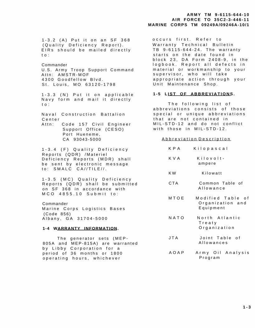
T h e g e n e r a t o r s e t s , m o d e l sMEP-805A and MEP-815A (F IGURE1 - 2 ) , a r e f u l l y e n c l o s e d , s e l f -c o n t a i n e d , s k i d - m o u n t e d ,p o r t a b l e u n i t s . T h e y a r ee q u i p p e d w i t h c o n t r o l s ,i n s t r u m e n t s a n d a c c e s s o r i e sn e c e s s a r y f o r o p e r a t i o n a ss i n g l e u n i t s o r i n p a r a l l e l w i t ha n o t h e r u n i t o f t h e s a m e c l a s sa n d m o d e . T h e g e n e r a t o r s e t sc o n s i s t o f a d i e s e l e n g i n e ,b r u s h l e s s g e n e r a t o r , e x c i t a t i o ns y s t e m , s p e e d g o v e r n i n g s y s t e m ,f u e l s y s t e m , 2 4 V D C s t a r t i n gs y s t e m , c o n t r o l s y s t e m a n d f a u l ts y s t e m .
NOTE
A l l l o c a t i o n s r e f e r -e n c e d i n F I G U R E 1 - 2a r e g i v e n f a c i n g t h ec o n t r o l p a n e l a s s e m b l y( r e a r ) o f t h e g e n e r a -t o r s e t .
1-7 LOCATION AND DESCRIPTION OFMAJOR COMPONENTS.
1 - 7 . 1 E n g i n e ( 1 9 ) . T h eg e n e r a t o r i s p o w e r e d b y a f o u rc y l i n d e r , f o u r c y c l e , f u e li n j e c t e d , t u r b o c h a r g e d , l i q u i d -c o o l e d d i e s e l e n g i n e w h i c ho c c u p i e s t h e f r o n t h a l f o f t h eg e n e r a t o r s e t . T h e e n g i n e i sa l s o e q u i p p e d w i t h a f u e lf i l t e r / w a t e r s e p a r a t o r , o i lf i l t e r , a n d a n a i r c l e a n e ra s s e m b l y . P r o t e c t i o n d e v i c e sa u t o m a t i c a l l y s t o p t h e e n g i n ed u r i n g c o n d i t i o n s o f h i g hc o o l a n t t e m p e r a t u r e , l o w o i lp r e s s u r e , n o f u e l , o v e r - s p e e d ,o r o v e r - v o l t a g e .
1 - 7 . 2 R a d i a t o r ( 2 2 ) . T h er a d i a t o r i s l o c a t e d a t t h e f r o n to f t h e g e n e r a t o r s e t . I t a c t sa s a h e a t e x c h a n g e r f o r t h ee n g i n e c o o l a n t .
1 - 7 . 3 M u f f l e r ( 3 ) . T h e m u f f l e ra n d e x h a u s t t u b i n g a r e c o n n e c t e dt o t h e e x h a u s t m a n i f o l d o n t h ee n g i n e . T h e e x h a u s t e x i t s f r o mt h e t o p o f t h e g e n e r a t o r s e th o u s i n g . G a s e s a r e e x h a u s t e du p w a r d .
1 - 7 . 4 S t a r t e r ( 9 ) . T h e s t a r t e ri s l o c a t e d o n t h e r i g h t s i d e o ft h e e n g i n e . T h e e l e c t r i cs t a r t e r m e c h a n i c a l l y e n g a g e s t h ee n g i n e f l y w h e e l i n o r d e r t os t a r t t h e d i e s e l e n g i n e .
1 - 7 . 5 B a t t e r y C h a r g i n gA l t e r n a t o r ( 6 ) . T h e b a t t e r yc h a r g i n g a l t e r n a t o r i s l o c a t e do n t h e r i g h t s i d e o f t h e e n g i n e .I t i s c a p a b l e o f m a i n t a i n i n g t h eb a t t e r i e s i n a s t a t e o f f u l lc h a r g e i n a d d i t i o n t o p r o v i d i n gt h e r e q u i r e d 2 4 V D C c o n t r o lp o w e r .
1 - 7 . 6 B a t t e r i e s ( 2 3 ) . T w ob a t t e r i e s a r e l o c a t e d a t f r o n to f t h e g e n e r a t o r s e t T h e .b a t t e r i e s a r e e l e c t r o l y t es e r v i c e a b l e , l e a d a c i d , 1 2 v o l tt y p e , c o n n e c t e d i n s e r i e s .A f t e r s t a r t i n g , t h e g e n e r a t o rs e t i s c a p a b l e o f o p e r a t i n g w i t hb a t t e r i e s r e m o v e d . A d i o d e a n da f u s e , l o c a t e d b e h i n d t h ec o n t r o l p a n e a s s e m b l y , p r o t e c tt h e g e n e r a t o r s e t i f t h eb a t t e r i e s a r e i n c o r r e c t l yconnected.
1 - 4
A R M Y T M 9 - 6 1 1 5 - 6 4 4 - 1 0A I R F O R C E T O 3 5 C 2 - 3 - 4 4 6 - 1 1
MARINE CORPS TM 09249A/09246A-10 /1
1234567891011
Malfunction Indicator PanelControl Panel AssemblyMuf f le rNATO Slave ReceptacleFan BeltBattery Charging AlternatorOil FilterDipstickStarterFuel Filter/Water SeparatorVoltage ReconnectionTermina l Board
12131 41 5161 718192 02 12 223
L o a d O u t p u t T e r m i n a l B o a r dS k i d B a s eC o n v e n i e n c e R e c e p t a c l eP a r a l l e l i n g R e c e p t a c l eA i r C l e a n e r A s s e m b l yA C G e n e r a t o rF u e l T a n kE n g i n eD e a d C r a n k S w i t c hW a t e r P u m pRad ia to rB a t t e r i e s
F I G U R E 1 - 2 . G e n e r a t o r S e t C o m p o n e n t s
1 - 5

A R M Y T M 9 - 6 1 1 5 - 6 4 4 - 1 0A I R F O R C E T O 3 5 C 2 - 3 - 4 4 6 - 1 1MARINE CORPS TM 09249A/09246A-10 /1
1 - 7 . 7 A i r C l e a n e r A s s e m b l y( 1 6 ) . T h e a i r c l e a n e r a s s e m b l yi s l o c a t e d o n t h e l e f t s i d eb e h i n d t h e a i r c l e a n e r a c c e s sd o o r . I t c o n s i s t s o f a d r y -t y p e , d i s p o s a b l e p a p e r e l e m e n ta n d c a n i s t e r . T h e a i r c l e a n e ra s s e m b l y f e a t u r e s a d u s tc o l l e c t o r w h i c h t r a p s l a r g e d u s tp a r t i c l e s . T h e a i r c l e a n e ra s s e m b l y h a s a r e s t r i c t i o ni n d i c a t o r w h i c h w i l l i n d i c a t ew h e n t h e a i r c l e a n e r e l e m e n tr e q u i r e s s e r v i c i n g .
1 - 7 . 8 F u e l T a n k ( 1 8 ) . T h e f u e lt a n k i s l o c a t e d b e l o w t h e e n g i n ea n d b e t w e e n t h e s k i d b a s e s i d em e m b e r s . T h e f u e l t a n k h a s ac a p a c i t y o f 2 3 g a l l o n s ( 8 7 . 1l i t e r s ) w h i c h w i l l a l l o w t h eg e n e r a t o r s e t t o o p e r a t e f o r a tl e a s t 8 h o u r s w i t h o u t r e f u e l i n g .
1 - 7 . 9 A C G e n e r a t o r ( 1 7 ) . T h eA C g e n e r a t o r i s a s i n g l eb e a r i n g , d r i p - p r o o f ,s y n c h r o n o u s , b r u s h l e s s , t h r e ep h a s e , f a n - c o o l e d g e n e r a t o r .T h e g e n e r a t o r i s c o u p l e dd i r e c t l y t o t h e r e a r o f t h ed i e s e l e n g i n e .
1 - 7 . 1 0 L o a d O u t p u t T e r m i n a lB o a r d ( 1 2 ) . T h e l o a d o u t p u tt e r m i n a l b o a r d i s l o c a t e d o n t h er i g h t s i d e ( r e a r ) o f t h eg e n e r a t o r s e t . T h e r e a r e f o u ro u t p u t t e r m i n a l s l o c a t e d o n t h eb o a r d . T h e y a r e m a r k e d L 1 , L 2 ,L 3 a n d L O . A f i f t h t e r m i n a l ,m a r k e d G N D , i s l o c a t e d n e x t t ot h e o u t p u t t e r m i n a l s a n d s e r v e sa s e q u i p m e n t g r o u n d f o r t h eg e n e r a t o r s e t . A r e m o v a b l e ,s o l i d c o p p e r b a r i s c o n n e c t e db e t w e e n t h e L O a n d G N Dt e r m i n a l s .
1 - 7 . 1 1 C o n t r o l P a n e l A s s e m b l y( 2 ) . T h e g e n e r a t o r s e t c o n t r o lp a n e l a s s e m b l y i s l o c a t e d a t t h er e a r o f t h e g e n e r a t o r s e t a n d
c o n t a i n s c o n t r o l s a n di n s t r u m e n t s f o r o p e r a t i n g t h ee n g i n e a n d t h e g e n e r a t o r .
1 - 7 . 1 2 M a l f u n c t i o n I n d i c a t o rP a n e l ( 1 ) . T h e m a l f u n c t i o ni n d i c a t o r p a n e l i s l o c a t e d t ot h e l e f t o f t h e c o n t r o l p a n e la s s e m b l y . I t i n d i c a t e sm a l f u n c t i o n s o f t h e g e n e r a t o rs e t c o m p o n e n t s .
1 - 7 . 1 3 N A T O S l a v e R e c e p t a c l e( 4 ) . T h e N A T O s l a v e r e c e p t a c l ei s l o c a t e d o n t h e r i g h t s i d e( f r o n t ) o f t h e g e n e r a t o r s e t .I t i s u s e d f o r s l a v e s t a r t i n g .
1 - 7 . 1 4 S k i d B a s e ( 1 3 ) . T h es k i d b a s e s u p p o r t s t h e g e n e r a t o rs e t . I t h a s f o r k l i f t a c c e s so p e n i n g s a n d c r o s s m e m b e r s f o rs h o r t d i s t a n c e m o v e m e n t . T h es k i d b a s e h a s p r o v i s i o n s i n t h eb o t t o m f o r i n s t a l l a t i o n o f t h eg e n e r a t o r s e t o n a t r a i l e r .
1 - 7 . 1 5 V o l t a g e R e c o n n e c t i o nT e r m i n a l B o a r d ( 1 1 ) . T h ev o l t a g e r e c o n n e c t i o n t e r m i n a lb o a r d i s l o c a t e d o n t h e r i g h ts i d e ( r e a r ) o f t h e g e n e r a t o rs e t . T h e b o a r d a l l o w sr e c o n f i g u r a t i o n f r o m 1 2 0 / 2 0 8 t o2 4 0 / 4 1 6 V A C o u t p u t .
1 - 7 . 1 6 F u e l F i l t e r / W a t e rS e p a r a t o r ( 1 0 ) . T h e f u e lf i l t e r / w a t e r s e p a r a t o r i sl o c a t e d i n t h e e n g i n ec o m p a r t m e n t o n t h e r i g h t s i d e .T h e e l e m e n t r e m o v e s i m p u r i t i e sa n d w a t e r f r o m t h e d i e s e l f u e l .
1 - 7 . 1 7 D i p s t i c k ( 8 ) . T h ed i p s t i c k i s l o c a t e d i n t h ee n g i n e c o m p a r t m e n t o n t h e r i g h ts i d e . T h e d i p s t i c k s h o w s t h el u b r i c a t i n g o i l l e v e l i n t h ee n g i n e c r a n k c a s e .
1 - 6
1-7.18 Oil Filter (7). The oilfilter is located in the enginecompartment on the left side. Thefilter removes impurities fromthe engine lubricating oil.
1-7.19 Fan Belt (5). The fanbelt is located in the enginecompartment on the front of theengine. The belt drives the fan,water pump and battery chargingalternator.
1-7.20 Water Pump (21). Thewater pump is located in theengine compartment on the frontof the engine. The pump circ-ulates the engine coolant throughthe engine block and theradiator.
1-7.23 Convenience Receptacle(22). The convenience receptacleis a 10 Amp, 120 VAC receptacleused to operate small plug intype equipment. It is protectedby a Ground Fault CircuitInterrupter located below themalfunction indicator (1-7.12),an overload circuit breakerlocated inside the control box,and an in-line fuse on generatorsets, contract number DAAK01-88-D-D082. The convenience recept-acle power is available at alltimes during operation of thegenerator set.
1-8 DIFFERENCES BETWEEN MODELS.The differences between models ofthe generator sets covered inthis manual are as follows:
1-7.21 Dead Crank Switch (20).The Dead Crank switch is loc-atedin the engine compartment on theleft side. The switch allowsthe engine to be cranked withoutstarting for maintenance.
Model MEP-805A is equipped witha 50/60 Hz generator.
Model MEP-815A is equipped witha 400 Hz generator.
1-7.22 Parallelins Receptacle.The paralleling receptacle isused to connect the parallelingcable bewteen two generator setsof the same size and mode tooperate in parallel.
1-9 EQUIPMENT DATA. For a listof Leading Particulars refer toTABLE 1-1.
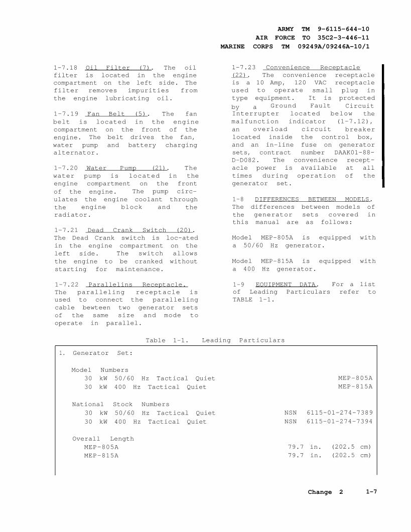
Table 1-1. Leading Particulars
1. Generator Set:
Model Numbers30 kW 50/60 Hz Tactical Quiet MEP-805A30 kW 400 Hz Tactical Quiet MEP-815A
National Stock Numbers30 kW 50/60 Hz Tactical Quiet NSN 6115-01-274-738930 kW 400 Hz Tactical Quiet NSN 6115-01-274-7394
Overall LengthMEP-805A 79.7 in. (202.5 cm)MEP-815A 79.7 in. (202.5 cm)
ARMY TM 9-6115-644-10AIR FORCE TO 35C2-3-446-11
MARINE CORPS TM 09249A/09246A-10/1
Change 2 1-7

ARMY TM 9-6115-644-10AIR FORCE TO 35C2-3-446-11MARINE CORPS TM 09249A/09246A-10/1
TABLE 1-1. Leading Particulars - continued
1. Generator Set - Continued:
Overall WidthMEP-805AMEP-815A
Overall HeightMEP-805AMEP-815A
Dry Weights (less Basic IssueItems)
MEP-805AMEP-815A
Wet WeightsMEP-805AMEP-815A
2. Engine:
ManufacturerModelType
DisplacementAltitude Degradation, 4000 ft(1220 m) to 8000 ft (2440m)Firing OrderCold Weather Starting AidSystem Use
Valve Tappet ClearanceAdjustment
Hot or Cold (Intake)Hot or Cold (Exhaust)
3. Cooling System:
TypeCapacityNormal Operating TemperatureTemperature Indicating SystemVoltage Rating
4. Lubricating System:
TypeOil Pump Type
35.7 in. (90.8 cm)35.7 in. (90.8 cm)
55 in. (139.7 cm)55 in. (139.7 cm)
2732 lb. (1239.2 kg.)2732 lb. (1239.2 kg.)
2931 lb. (1329.5 kg.)2931 lb. (1329.5 kg.)
John Deere4039T
Four cylinder, four cycle,turbocharged diesel
239 cu. in. (3.9 liters)3.5% per 1000 ft (305 m)
1, 3, 4, 2When temperature is 40°F
(4°C) or below
0.014 in. (0.35 cm)0.018 in. (0.45 cm)
Pressurized radiator and pump15.5 qts. (14.7 liters)
170-200°F (77-93°C)24 VDC
Full flow, circulating pressurePositive displacement gear
1-8 Change 2

A R M Y T M 9 - 6 1 1 5 - 6 4 4 - 1 0A I R F O R C E T O 3 5 C 2 - 3 - 4 4 6 - 1 1
MARINE CORPS TM 09249A/09246A-10 /1
T A B L E 1 - 1 . L e a d i n g P a r t i c u l a r - C o n t i n u e d
4 . L u b r i c a t i n g S y s t e m - C o n t i n u e d :
N o r m a l O p e r a t i n g P r e s s u r e 2 5 - 6 0 p s i ( 1 7 2 - 4 1 4 k P a )O i l F i l t e r T y p e F u l l f l o w , s p i n - o n , r e p l a c e a b l e e l e m e n tL u b r i c a t i n g S y s t e m C a p a c i t y 1 5 q t s . ( 1 4 . 2 l i t e r s )
P r e s s u r e I n d i c a t i n g S y s t e mVoltage Rating 24 VDC
5 . F u e l S y s t e m :
Type of Fuel DF-1, DF-2, DF-A, JP4, JP5, JP8Fuel Tank Capacity 23 gal. (87.1 liters)Fuel Consumption Rate: 50/60 Hz
A u x i l i a r y F u e l P u m p :Voltage Rating 24 VDC Delivery Pressure 5.0-6.5 psi (34.5-65.5 kPA) (max)
F u e l L e v e l S w i t c h :Type FloatCurrent 3.0 amp at 6 to 32 VDC
6 . E n g i n e S t a r t i n g S y s t e m :
Batteries Two 12 volt, connected in seriesStarter:
2 . 6 0 g a l ( 9 . 8 l i t e r s ) p e r h o u r4 0 0 H z
2 . 7 5 g a l . ( 1 0 . 4 l i t e r s ) p e r h o u r
Manufacturer Nippondenso Co. LtdModel RE39930AVoltage Rating 24 VDCDrive Type Gear Reduction
B a t t e r y C h a r g i n g A l t e r n a t o r :Manufacturer PrestoliteModel 8EM3002GCRating 42 amps at 24 VDCProtective Fuse 30 amps
7 . A C G e n e r a t o r :M E P - 8 0 5 A M E P - 8 1 5 A
Manufacturer Marathon MarathonE l e c t r i c E l e c t r i c
1 - 9

A R M Y T M 9 - 6 1 1 5 - 6 4 4 - 1 0A I R F O R C E T O 3 5 C 2 - 3 - 4 4 6 - 1 1MARINE CORPS TM 09249A/09246A-10 /1
T A B L E 1 - 1 . L e a d i n g P a r t i c u l a r s - C o n t i n u e d
7 . A C G e n e r a t o r - C o n t i n u e d :
5 0 H z :
c o u p l i n g c o u p l i n g
8 .
9 .
T y p e
L o a d C a p a c i t y 3 0 k W 3 0 k W
C u r r e n t R a t i n g s : 6 0 H z : 4 0 0 H z :120 /208 vo l t connec t ion 104 amps 104 amps240/416 volt connection 52 amps 52 amps
120/208 volt connection 86 amps240/416 volt connection 43 amps
Power Factor 0.8 0.8
Cooling fan cooled fan cooled
Drive Type direct direct
Duty Classification continuous continuous
G o v e r n i n g S y s t e m :
L o a d M e a s u r i n g U n i t :Manufacturer Technology ResearchModel 19310
G o v e r n o r C o n t r o l U n i t :Manufacturer Barber-ColmanModel DYNA 10502-002-0-2
P r o t e c t i o n D e v i c e s :
M E P - 8 0 5 A M E P - 8 1 5 A
Rotating Rotatingfield fields y n c h r o n o u s s y n c h r o n o u s
L o w O i l P r e s s u r e S w i t c h :Trip Pressure 15 ± 3 psi (103.4 ± 20.7 kPa)Voltage Rating 24VDCCurrent Rating 5 amps
C o o l a n t H i g h T e m p e r a t u r e S w i t c h :Trip Temperature 225 ± 5° F (107 ± 3° C) Voltage Rating 12-120 VDCCurrent Rating 2 amps
1-10

ARMY TM 9-6115-644-10AIR FORCE TO 35C2-3-446-11
MARINE CORPS TM 09249A/09246A-10/1
Table 1-1. Leading Particulars - Continued
9. Protection Devices:
Speed Switch: Element Trip and Reset 2200 ± 40 RPMVoltage Rating 28 VDCCurrent Rating 1 amp
O v e r v o l t a g e :Trip P oint Conditions 153 ± 3 VAC for
no less than200 milliseconds (120
VAC coil winding)
Trip Point No more than 1.25seconds after trip
conditions exist
1-11

ARMY TM 9-6115-644-10AIR FORCE TO 35C2-3-446-11MARINE CORPS TM 09249A/09246A-10/1
SECTION III. TECHNICAL PRINCIPLES OF OPERATION
1-10 INTRODUCTION. This section contains func-tional descriptions of the generator set and explainshow the controls and indicators interact with the sys-tem.
1-11 ENGINE STARTING SYSTEM.
The Engine Starting System (Figure 1-3), consists of two12-volt batteries connected in series, a starter, a 24 voltbattery charging alternator, a magnetic pickup (for sensingengine speed) and the related switches and relays requiredfor control of the starting system. For engine cranking,battery power is supplied to the starter motor through thestarter solenoid which in turn is controlled by the crankingrelay. The starter then engages the engine flywheel caus-ing the engine to turnover. For engine starting, the DEADCRANK switch must be in the NORMAL position, theDC Control power circuit breaker must be pushed in, theEMERGENCY STOP switch must be in the OUT posi-tion and the MASTER SWITCH is moved to the STARTposition. The cranking relay is then controlled by a circuitconsisting of the start relay and crank disconnect switch.As the engine accelerates to the preset speed (sensed bythe magnetic pickup), the crank disconnect switch opensand deenergizes the cranking relay to stop and disengagethe starter. The starting sequence may also be stopped bymoving the MASTER SWITCH to OFF. The engine maybe cranked without starting by use of the DEAD CRANKswitch. With the DEAD CRANK switch in the CRANKposition, the cranking relay, starter solenoid and startermotor are energized without activating any other startingor control function.
Figure 1-3. Engine Starting System
1-12 Change 1

The batteries are charged by the battery charging alterna-tor that is belt driven by the engine. Generator set controlsystem power is also supplied by the battery chargingalternator. The BATTERY CHARGE ammeter indicatesthe charge/discharge rate of the batteries, from-10 AMPSto +20 AMPS, in 5 AMPS increments. Normal operatingindication depends on the state of charge in the batteries.A low charge, such as exists immediately after enginestarting, will cause a high reading (needle moves towardCHARGE area). When the charge in the batteries has beenrestored, the indicator moves near zero.
1-12 FUEL SYSTEM.1-12.1 The Fuel System (Figure 1-4), consists of piping,fuel tank, transfer pump, fuel filter/water separator, injec-tion pump and injectors. Fuel is drawn from the fuel tankby the transfer pump. After reaching the transfer pump,fuel passes through a fuel falter/water separator wherewater and small impurities are removed. The fuel thengoes to an injection pump where it is pressurized andpushed into the injectors. Through the injectors fuel entersthe diesel engine combustion chamber, where it is mixedwith air and ignited. The fuel that is not used is returnedto the fuel tank via an excess fuel return line.
1-12.2 The Auxiliary Fuel System consists of extenalfuel supply, fuel filter, piping, a 24 VDC auxiliary fuelpump and a fuel level float switch. When the MASTERSWITCH is set on PRIME & RUN AUX FUEL it actu-ates the auxiliary fuel pump and transfers fuel from theexternal fuel supply to the generator fuel tank The fuellevel float
ARMY TM 9-6115-644-10AIR FORCE TO 35C2-3-446-11
MARINE CORPS TM 09249A/09246A-10/1
Figure 1-4. Fuel System
Change 1 1-13

ARMY TM 9-6115-644-10AIR FORCE TO 35C2-3-44611MARINE CORPS TM 09249A/09246A- 10/1
switch shuts off the auxiliary fuel pump when the genera-tor fuel tank is full and reactivates the pump as the leveldrops. The FUEL LEVEL indicator indicates fuel level ofgenerator fuel tank from (E) empty to (F) full in quartertank increments.
1-13 ENGINE COOLING SYSTEM.1-13.1 The Engine Cooling System (Figure 1-5) consistsof a radiator, hoses, thermostat water pump, a belt drivenfan, cooling jackets and oil cooler. The water pump forcescoolant through passages (cooling jackets) in the engineblock and cylinder head where the coolant absorbs heatfrom the engine. When the engine reaches normal operat-ing temperature, the thermostat opens and the heated cool-ant flows through the upper radiator hose assembly intothe radiator. The cooling fan circulates air through theradiator where the coolant temperature is reduced.
1-13.2 A coolant high temperature switch provides auto-matic shut down in the event that coolant temperatureexceeds 225 ± 5°F (107 + 3±C). The COOLANT TEMPindicator indicates the engine coolant temperature, from120°F to 240°F (48°C to 115°C).
Figure 1-5. Engine Cooling System
1-14 Change 1

A R M Y T M 9 - 6 1 1 5 - 6 4 4 - 1 0A I R F O R C E T O 3 5 C 2 - 3 - 4 4 6 - 1 1
MARINE CORPS TM 09249A/09246A-10 /1
1-14 LUBRICATION SYSTEM.
T h e L u b r i c a t i o n S y s t e m( F I G U E 1 - 6 ) c o n s i s t s o f a n o i l
p a n , d i p s t i c k , p u m p , o i lp r e s s u r e s e n d e r , A O A P s a m p l ev a l v e , a n d f i l t e r . T h e o i l p a ni s a r e s e r v o i r f o r e n g i n el u b r i c a t i n g o i l . T h e d i p s t i c ki n d i c a t e s o i l l e v e l i n t h e o i lp a n . A p u m p d r a w s o i l f r o m t h eo i l p a n a n d t h r o u g h a s c r e e nr e m o v i n g l a r g e i m p u r i t i e s . T h eo i l t h e n p a s s e s t h r o u g h a s p i n -o n t y p e f i l t e r w h e r e s m a l li m p u r i t i e s a r e r e m o v e d . F r o mt h e f i l t e r , o i l e n t e r s t h ee n g i n e a n d i s d i s t r i b u t e d t o t h ee n g i n e ’ s i n t e r n a l m o v i n g p a r t s .A f t e r p a s s i n g t h r o u g h t h ee n g i n e , t h e o i l r e t u r n s t o t h eo i l p a n . T h e O I L P R E S S U R Ei n d i c a t o r i n d i c a t e s o i l p r e s s u r es e n s e d b y t h e o i l p r e s s u r es e n d e r i n t h e e n g i n e . T h ee n g i n e w i l l s h u t o f fa u t o m a t i c a l l y i f t h e o i lp r e s s u r e d r o p s t o a d a n g e r o u s l yl o w l e v e l . T h e o i l l e v e l c a n b ec h e c k e d w i t h e n g i n e r u n n i n g .
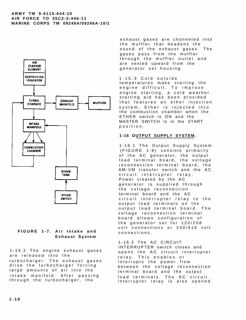
1-15 AIR INTAKE AND EXHAUSTSYSTEM.
1 - 1 5 . 1 T h e A i r I n t a k e a n dE x h a u s t S y s t e m ( F I G U R E 1 - 7 ) ,c o n s i s t s o f a n a i r c l e a n e ra s s e m b l y , i n t a k e m a n i f o l d ,t u r b o c h a r g e r , e x h a u s t m a n i f o l da n d m u f f l e r . A m b i e n t a i r i sd r a w n i n t o t h e a i r c l e a n e ra s s e m b l y w h e r e i t p a s s e s t h r o u g ht h e a i r c l e a n e r e l e m e n t .A i r b o r n e d i r t i s r e m o v e d a n dt r a p p e d i n t h e e l e m e n t . Ar e s t r i c t i o n i n d i c a t o r , l o c a t e do n t h e a i r c l e a n e r a s s e m b l yh o u s i n g , d i s p l a y s r e d w h e n t h ea i r c l e a n e r e l e m e n t s h o u l d b es e r v i c e d . D i r t c a n b e r e m o v e df r o m t h e a i r c l e a n e r h o u s i n g b yp i n c h i n g a n e v a c u a t o r v a l v e .
F I G U R E 1 - 6 . E n g i n e L u b r i c a t i o nSystem
F i l t e r e d a i r i s d r a w n o u t o f t h ea i r c l e a n e r a s s e m b l y t h r o u g h a i ri n t a k e t u b e s t o t h e t u r b o c h a r g e rw h e r e i t i s f o r c e d i n t o t h ei n t a k e m a n i f o l d t o t h e c o m b u s i o nc h a m b e r s a n d m i x e d w i t h f u e lf r o m t h e i n j e c t o r s .
1 - 1 5
A R M Y T M 9 - 6 1 1 5 - 6 4 4 - 1 0A I R F O R C E T O 3 5 C 2 - 3 - 4 4 6 - 1 1MARINE CORPS TM 09249A/09246A-10 /1
F I G U R E 1 - 7 . A i r I n t a k e a n dE x h a u s t S y s t e m
1 - 1 5 . 2 T h e e n g i n e e x h a u s t g a s e sa r e r e l e a s e d i n t o t h et u r b o c h a r g e r . T h e e x h a u s t g a s e sd r i v e t h e t u r b o c h a r g e r f o r c i n gl a r g e a m o u n t s o f a i r i n t o t h ei n t a k e m a n i f o l d . A f t e r p a s s i n gt h r o u g h t h e t u r b o c h a r g e r , t h e
e x h a u s t g a s e s a r e c h a n n e l e d i n t ot h e m u f f l e r t h a t d e a d e n s t h es o u n d o f t h e e x h a u s t g a s e s . T h eg a s e s p a s s f r o m t h e m u f f l e rt h r o u g h t h e m u f f l e r o u t l e t a n da r e v e n t e d u p w a r d f r o m t h eg e n e r a t o r s e t h o u s i n g .
1 - 1 5 . 3 C o l d o u t s i d et e m p e r a t u r e s m a k e s t a r t i n g t h ee n g i n e d i f f i c u l t . T o i m p r o v ee n g i n e s t a r t i n g , a c o l d w e a t h e rs t a r t i n g a i d h a s b e e n p r o v i d e dt h a t f e a t u r e s a n e t h e r i n j e c t i o ns y s t e m . E t h e r i s i n j e c t e d i n t ot h e c o m b u s t i o n c h a m b e r w h e n t h eE T H E R s w i t c h i s O N a n d t h eMASTER SWITCH is in the STARTp o s i t i o n .
1-16 OUTPUT SUPPLY SYSTEM.
1 - 1 6 . 1 T h e O u t p u t S u p p l y S y s t e m( F I G U R E 1 - 8 ) c o n s i s t s p r i m a r i l yo f t h e A C g e n e r a t o r , t h e o u t p u tl o a d t e r m i n a l b o a r d , t h e v o l t a g er e c o n n e c t i o n t e r m i n a l b o a r d , t h eA M - V M t r a n s f e r s w i t c h a n d t h e A Cc i r c u i t i n t e r r u p t e r r e l a y .P o w e r c r e a t e d b y t h e A Cg e n e r a t o r i s s u p p l i e d t h r o u g ht h e v o l t a g e r e c o n n e c t i o nt e r m i n a l b o a r d a n d t h e A Cc i r c u i t i n t e r r u p t e r r e l a y t o t h eo u t p u t l o a d t e r m i n a l s o n t h eo u t p u t l o a d t e r m i n a l b o a r d . T h ev o l t a g e r e c o n n e c t i o n t e r m i n a lb o a r d a l l o w s c o n f i g u r a t i o n o ft h e g e n e r a t o r s e t f o r 1 2 0 / 2 0 8v o l t c o n n e c t i o n s o r 2 4 0 / 4 1 6 v o l tc o n n e c t i o n s .
1 - 1 6 . 2 T h e A C C I R C U I TI N T E R R U P T E R s w i t c h c l o s e s a n do p e n s t h e A C c i r c u i t i n t e r r u p t e rr e l a y . T h i s e n a b l e s o ri n t e r r u p t s t h e p o w e r f l o wb e t w e e n t h e v o l t a g e r e c o n n e c t i o nt e r m i n a l b o a r d a n d t h e o u t p u tl o a d t e r m i n a l s . T h e A C c i r c u i ti n t e r r u p t e r r e l a y i s a l s o o p e n e d
1 - 1 6

a u t o m a t i c a l l y d u r i n g a n y o f t h es p e c i f i e d s e t f a u l t s T h e .v o l t a g e r e g u l a t o r s e n s e s A Cg e n e r a t o r o u t p u t v o l t a g e a n dp r o v i d e s c o n t r o l v o l t a g e t o t h eA C g e n e r a t o r e x c i t e r t o m a i n t a i nt h e d e s i r e d A C g e n e r a t o r o u t p u tv o l t a g e . T h e p o s i t i o n o f t h eA M - V M t r a n s f e r s w i t c h s e l e c t st h e o u t p u t l o a d t e r m i n a l s f r o mw h i c h c u r r e n t a n d v o l t a g e a r em e a s u r e d a n d a r e i n d i c a t e d o nt h e A C v o l t m e t e r ( V O L T S A C ) a n dthe ammeter (PERCENT RATEDCURRENT).
A R M Y T M 9 - 6 1 1 5 - 6 4 4 - 1 0A I R F O R C E T O 3 5 C 2 - 3 - 4 4 6 - 1 1
MARINE CORPS TM 09249A/09246A-10 /1
F I G U R E 1 - 8 . O u t p u t S u p p l yS y s t e m
1 - 1 7 / ( 1 - 1 8 b l a n k )


A R M Y T M 9 - 6 1 1 5 - 6 4 4 - 1 0A I R F O R C E T O 3 5 C 2 - 3 - 4 4 6 - 1 1
MARINE CORPS TM 09249A/09246A-10 /1
CHAPTER 2
OPERATING INSTRUCTIONS
SECTION I. DESCRIPTION AND USE OF OPERATOR’SCONTROLS AND INDICATORS
2 - 1 G E N E R A L . 2-2 CONTROL PANEL ASSEMBLY.
T h i s s e c t i o n d e s c r i b e s a n d T h e c o n t r o l p a n e l a s s e m b l yi l l u s t r a t e s t h e c o n t r o l s a n d c o n t a i n s m o s t o f t h e o p e r a t i n gi n d i c a t o r s t o e n s u r e p r o p e r c o n t r o l s a n d i n d i c a t o r s f o r t h eo p e r a t i o n o f t h e g e n e r a t o r s e t . g e n e r a t o r s e t . F I G U R E 2 - 1 s h o w s
t h e c o n t r o l p a n e l a s s e m b l yl a y o u t a n d T A B L E 2 - 1 d e s c r i b e se a c h c o n t r o l a n d i n d i c a t o r .
2 - 1

A R M Y T M 9 - 6 1 1 5 - 6 4 4 - 1 0A I R F O R C E T O 3 5 C 2 - 3 - 4 4 6 - 1 1MARINE CORPS TM 09249A/09246A-10 /1
F I G U R E 2 - 1 . C o n t r o l P a n e l / C o n t r o l s B r a c k e t A s s e m b l y
2 - 2

A R M Y T M 9 - 6 1 1 5 - 6 4 4 - 1 0A I R F O R C E T O 3 5 C 2 - 3 - 4 4 6 - 1 1
MARINE CORPS TM 09249A/09246A-10 /1
T A B L E 2 - 1 . C o n t r o l P a n e l C o n t r o l s a n d I n d i c a t o r s
F u n c t i o nK e y
1
C o n t r o l o r I n d i c a t o r
F U E L L E V E L i n d i c a t o r I n d i c a t e s f u e l l e v e l .
I l l u m i n a t e s c o n t r o l p a n e l .
I n d i c a t e s e n g i n e c o o l a n tt e m p e r a t u r e .
2 P a n e l l i g h t s
C O O L A N T T E M P . i n d i c a t o r3
A c t i v a t e s o r d e a c t i v a t e s c o l ds t a r t i n g a i d s y s t e m .
A c t i v a t e s o r d e a c t i v a t e s p a n e llights.
4 E T H E R s w i t c h
P A N E L L I G H T S s w i t c h5
FREQUENCY meter (HERTZ) I n d i c a t e s g e n e r a t o r s e t o u t p u tfrequency.
I n d i c a t e s g e n e r a t o r s e t l o a dc u r r e n t a s a p e r c e n t o f r a t e dc u r r e n t .
6
7
8
Ammeter (PERCENT RATEDCURRENT)
A l l o w s s e l e c t i o n o f c u r r e n t a n dv o l t a g e r e a d i n g s b e t w e e n o u t p u tl o a d t e r m i n a l s a s f o l l o w s :
S w i t c hP o s i t i o n V o l t a q e C u r r e n tL 1 - L O 1 2 0 * 2 4 0 * * L 1L 2 - L O 1 2 0 * 2 4 0 * * L 2L 3 - L O 1 2 0 * 2 4 0 * *L 1 - L 2 2 0 8 * 4 1 6 * * N o n eL2 - L3 2 0 8 * 4 1 6 * * N o n eL1 - L3 2 0 8 * 4 1 6 * * None
A C R e c o n n e c t i o n T e r m i n a l B o a r dS e t t i n g* 120/208** 240/416
A M - V M t r a n s f e r s w i t c h
L 3
9 K i l o w a t t m e t e r(PERCENT POWER)
I n d i c a t e s g e n e r a t o r s e t o u t p u tD o w e r a s a p e r c e n t o f r a t e d p o w e r .
1 0 A C V o l t m e t e r ( V O L T S A C ) I n d i c a t e s o u t p u t v o l t a g e o fg e n e r a t o r s e t .
B A T T L E S H O R T l i g h t
V O L T A G E a d j u s tP o t e n t i o m e t e r
A m b e r l i q h t i n d i c a t e s s w i t c h o n .1 1
12 A d j u s t s g e n e r a t o r s e t v o l t a g e .
B A T T L E S H O R T s w i t c h B y p a s s e s p r o t e c t i v e d e v i c e s .13
2 - 3
A R M Y T M 9 - 6 1 1 5 - 6 4 4 - 1 0A I R F O R C E T O 3 5 C 2 - 3 - 4 4 6 - 1 1MARINE CORPS TM 09249A/09246A-10 /1
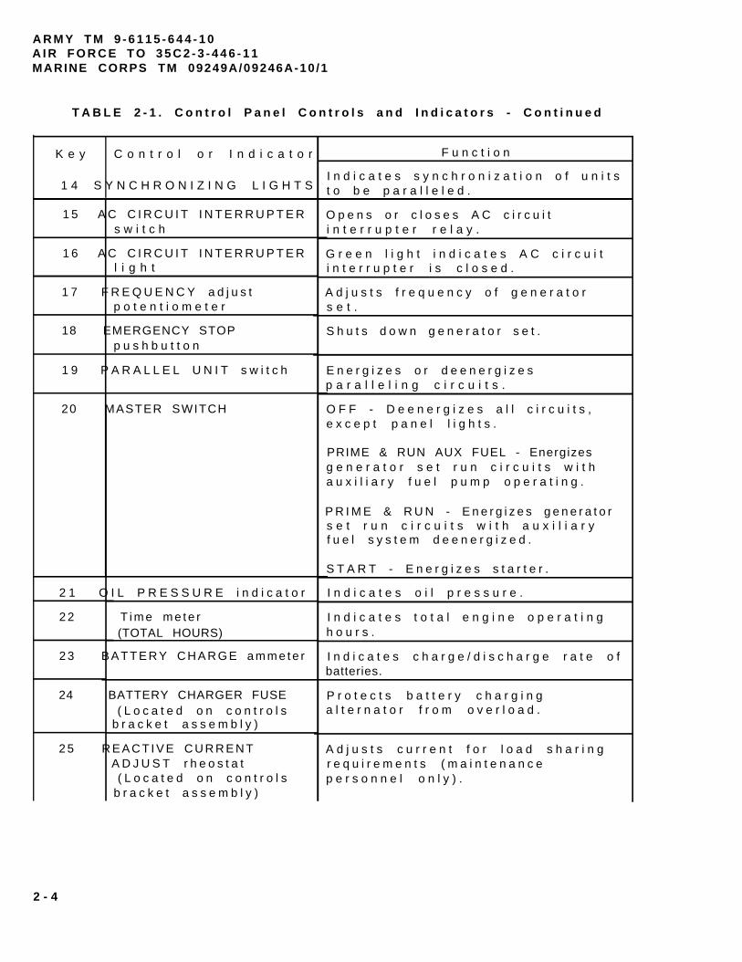
T A B L E 2 - 1 . C o n t r o l P a n e l C o n t r o l s a n d I n d i c a t o r s - C o n t i n u e d
K e y C o n t r o l o r I n d i c a t o r
1 4 S Y N C H R O N I Z I N G L I G H T S
1 5 A C C I R C U I T I N T E R R U P T E Rs w i t c h
1 6 A C C I R C U I T I N T E R R U P T E Rl i g h t
1 7 F R E Q U E N C Y a d j u s tp o t e n t i o m e t e r
18 EMERGENCY STOPp u s h b u t t o n
1 9 P A R A L L E L U N I T s w i t c h
20 MASTER SWITCH
2 1 O I L P R E S S U R E i n d i c a t o r
2 2 T i m e m e t e r(TOTAL HOURS)
2 3 B A T T E R Y C H A R G E a m m e t e r
24 BATTERY CHARGER FUSE( L o c a t e d o n c o n t r o l s
b r a c k e t a s s e m b l y )
2 5 R E A C T I V E C U R R E N TA D J U S T r h e o s t a t( L o c a t e d o n c o n t r o l s
b r a c k e t a s s e m b l y )
F u n c t i o n
I n d i c a t e s s y n c h r o n i z a t i o n o f u n i t st o b e p a r a l l e l e d .
O p e n s o r c l o s e s A C c i r c u i ti n t e r r u p t e r r e l a y .
G r e e n l i g h t i n d i c a t e s A C c i r c u i ti n t e r r u p t e r i s c l o s e d .
A d j u s t s f r e q u e n c y o f g e n e r a t o rs e t .
S h u t s d o w n g e n e r a t o r s e t .
E n e r g i z e s o r d e e n e r g i z e sp a r a l l e l i n g c i r c u i t s .
O F F - D e e n e r g i z e s a l l c i r c u i t s ,e x c e p t p a n e l l i g h t s .
PRIME & RUN AUX FUEL - Energizesg e n e r a t o r s e t r u n c i r c u i t s w i t ha u x i l i a r y f u e l p u m p o p e r a t i n g .
P R I M E & R U N - E n e r g i z e s g e n e r a t o rs e t r u n c i r c u i t s w i t h a u x i l i a r yf u e l s y s t e m d e e n e r g i z e d .
S T A R T - E n e r g i z e s s t a r t e r .
I n d i c a t e s o i l p r e s s u r e .
I n d i c a t e s t o t a l e n g i n e o p e r a t i n gh o u r s .
I n d i c a t e s c h a r g e / d i s c h a r g e r a t e o fbatteries.
P r o t e c t s b a t t e r y c h a r g i n ga l t e r n a t o r f r o m o v e r l o a d .
A d j u s t s c u r r e n t f o r l o a d s h a r i n gr e q u i r e m e n t s ( m a i n t e n a n c ep e r s o n n e l o n l y ) .
2 - 4
ARMY TM 9-6115-644-10AIR FORCE TO 35C2-3-446-11
MARINE CORPS TM 09249A/09246A-10/1
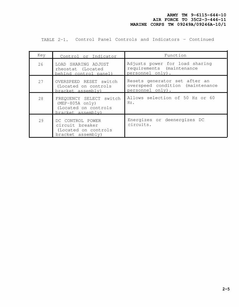
TABLE 2-1. Control Panel Controls and Indicators - Continued
Key
26
27
28
29
Control or Indicator
LOAD SHARING ADJUSTrheostat (Locatedbehind control panel)
OVERSPEED RESET switch(Located on controlsbracket assembly)
FREQUENCY SELECT switch(MEP-805A only)(Located on controlsbracket assembly)
DC CONTROL POWERcircuit breaker(Located on controlsbracket assembly)
Function
Adjusts power for load sharingrequirements (maintenancepersonnel only).
Resets generator set after anoverspeed condition (maintenancepersonnel only).
Allows selection of 50 Hz or 60Hz.
Energizes or deenergizes DCcircuits.
2-5

ARMY TM 9-6115-644-10AIR FORCE TO 35C2-3-446-11MARINE CORPS TM 09249A/09246A-10/1
2-3 MALFUNCTION INDICATORPANEL,
The malfunction indicatorpanel (FIGURE 2-2) is located tothe left of the control panel.
It contains a series of lightswhich indicate a generator setfailure or abnormal operatingcondition. TABLE 2-2 describeseach indicator light.
FIGURE 2-2. Malfunction Indicator Panel
2-6 Change 2

ARMY TM 9-6115-644110AIR FORCE TO 35C2-3-446-21
MARINE CORPS TM 09249A/09246A-10/1
TABLE 2-2. Malfunction Indicator Panel
Key Control or Indicator Function
1 NO FUEL indicator Lights when fuel level in fuel tankis below preset level.
2 COOLANT HIGH TEMP Lights when engine coolantindicator temperature exceeds 225° ± 5° F
(107° ± 3° F).
3 OVERVOLTAGE indicator Lights when voltage in 120 voltgenerator coil exceeds 153 ± 3volts.
4 OVERSPEED indicator Lights when engine speed exceeds 2200± 40 RPM.
5 REVERSE POWER indicator Lights when power flow into generatorset exceeds 20 ± 3 percent of ratedcurrent.
6 OVER LOAD indicator Lights when current in any phaseexceeds 110 percent of rated current.
7 GROUND FAULT CIRCUIT Tests GROUND FAULT CIRCUITINTERRUPTER TEST INTERRUPTER.pushbutton
8 GROUND FAULT CIRCUIT Indicates a ground fault condition.INTERRUPTER indicator
9 GROUND FAULT CIRCUIT Rests GROUND FAULT CIRCUITINTERRUPTER RESET INTERRUPTER.pushbutton
10 SHORT CIRCUIT indicator Lights when generator set output inany phase exceeds 425 ± 25 percentof rated current.
11 UNDER VOLTAGE indicator Lights when voltage in 120 voltgenerator coil winding drops below99 ± 4 VAC.
12 PUSH TEST RESET LAMPS Tests and resets fault indicatorswitch lamps.
13 LOW OIL PRESSURE Lights when engine lubricationindicator systems pressure is less than 15 ± 3
psi (103.4 ± 20.7 kPa) during engineoperation.
14 Convenience Receptacle Circuit breaker trips on when loadOverload Circuit on convenience receptacle exceeds 10Breaker (lo-amp in-line amps (fuse blows on generator sets,fuse on generator sets, contract number DAAK01-88-D-D082).contract number DAAK01-88-D-DO82)
Change 2 2-7

A R M Y T M 9 - 6 1 1 5 - 6 4 4 - 1 0A I R F O R C E T O 3 5 C 2 - 3 - 4 4 6 - 1 1MARINE CORPS TM 09249A/09246A-10 /1
SECTION II. PREVENTIVE MAINTENANCE CHECKS AND SERVICES (PMCS)
2 - 4 G E N E R A L .
T o e n s u r e t h a t t h eg e n e r a t o r s e t i s r e a d y f o ro p e r a t i o n a t a l l t i m e s , i t m u s tb e i n s p e c t e d s o t h a t d e f e c t s c a nb e d i s c o v e r e d a n d c o r r e c t e db e f o r e t h e y r e s u l t i n s e r i o u sd a m a g e o r f a i l u r e .
2 - 4 . 1 B e f o r e Y o u O p e r a t e .A l w a y s k e e p i n m i n d t h e C A U T I O N Sa n d W A R N I N G S . P e r f o r m y o u rb e f o r e ( B ) P M C S .
2 - 4 . 2 W h i l e Y o u O p e r a t e .A l w a y s k e e p i n m i n d t h e C A U T I O N Sa n d W A R N I N G S . P e r f o r m y o u rd u r i n g ( D ) P M C S .
2 - 4 . 3 A f t e r Y o u O p e r a t e . B es u r e t o p e r f o r m y o u r a f t e r ( A )PMCS.
2 - 4 . 4 I f Y o u r E q u i p m e n t F a i l st o O p e r a t e . I f y o u r e q u i p m e n td o e s n o t p e r f o r m a s r e q u i r e d ,r e f e r t o C h a p t e r 3 u n d e rT r o u b l e s h o o t i n g f o r p o s s i b l ep r o b l e m s . R e p o r t a n ym a l f u n c t i o n s o r f a i l u r e s o nD A F o r m 2 4 0 4 , r e f e r t oD A P A M 7 3 8 - 7 5 0 .
2-5 PMCS PROCEDURES.
NOTE
2 - 5 . 1 P u r p o s e o f P M C S T a b l e .Y o u r P r e v e n t i v e M a i n t e n a n c eC h e c k s a n d S e r v i c e s ( T A B L E 2 - 3 )l i s t t h e i n s p e c t i o n s a n d c a r e o fy o u r e q u i p m e n t r e q u i r e d t o k e e pi t i n g o o d o p e r a t i n g c o n d i t i o n .
2 - 5 . 2 P u r p o s e o f S e r v i c eI n t e r v a l s . T h e i n t e r v a l c o l u m no f y o u r P M C S t a b l e t e l l s y o uw h e n t o d o a c e r t a i n c h e c k o rs e r v i c e .
2 - 5 . 3 S p e c i a l I n s t r u c t i o n s .T h e f o l l o w i n g g u i d e l i n e s h a v eb e e n p r o v i d e d t o h e l p y o u i nc l a s s i f y i n g l e a k s o b s e r v e d w h i l ep e r f o r m i n g P M C S .
C l a s s I . S e e p a g e o f f l u i d( a s i n d i c a t e d b y w e t n e s s o r
d i s c o l o r a t i o n ) n o t g r e a t e n o u g ht o f o r m d r o p s .
C l a s s I I . L e a k a g e o f f l u i dg r e a t e n o u g h t o f o r m d r o p s b u tn o t e n o u g h t o c a u s e d r o p s t od r i p f r o m i t e m b e i n gc h e c k e d / i n s p e c t e d .
C l a s s I I I . L e a k a g e o ff l u i d g r e a t e n o u g h t o f o r m d r o p st h a t f a l l f r o m t h e i t e m b e i n gc h e c k e d / i n s p e c t e d .
F o r g e n e r a l l o c a t i o no f i t e m s t o b e i n -s p e c t e d i n T A B L E 2 - 3 ,r e f e r t o F I G U R E 1 - 2a n d F I G U R E 2 - 1 .
2 - 8

Equipment operation is allowable with minor oiland coolant leakage (Class I or II).
Of course, you must consider the fluid capacityin the item/system being checked/inspected.When in doubt, notify the next higher level ofmaintenance.
When operating with Class I or Class II leaks,continue to check fluid levels as required inyour PMCS. All leaks should be reported to thenext higher level of maintenance.
2-5.4 Procedures Column. The procedures column of
ARMY TM 9-6115-644-10AIR FORCE TO 35C2-3-446-11
MARINE CORPS TM 09249A/09246A-10/1
2-5.5 The “Equipment Is Not Ready/AvailableIf”. This column tells you when and why the generatorset cannot be used.
NOTE
The terms ready/available and mission capa-ble refer to the same status: Generator set is onhand and is able to perform its combat mis-sions, refer to DA PAM 738-750.
2-5.6 Reporting and Correcting Deficiencies. If yourgenerator set does not perform as required, refer to Chap-ter 3 under Troubleshooting for possible problems. Report
your PMCS table tells you how to do the required checksand services. Carefully follow these instructions. If youdo not have the tools, or if the procedures indicate, com-plete a DA Form 2404 and submit it to the next higherlevel of maintenance.
any malfunctions of failures on DA Form 2404, refer toDA PAM 738-750.
2-5.7 Removal of Assemblies/Equipment to PerformPMCS. There is no requirement to remove assemblies/equipment prior to performing the PMCS.
2 - 9
ARMY TM 9-6115-644-10AIR FORCE TO 35C2-3-446-11MARINE CORPS TM 09249A/09246A-10/1
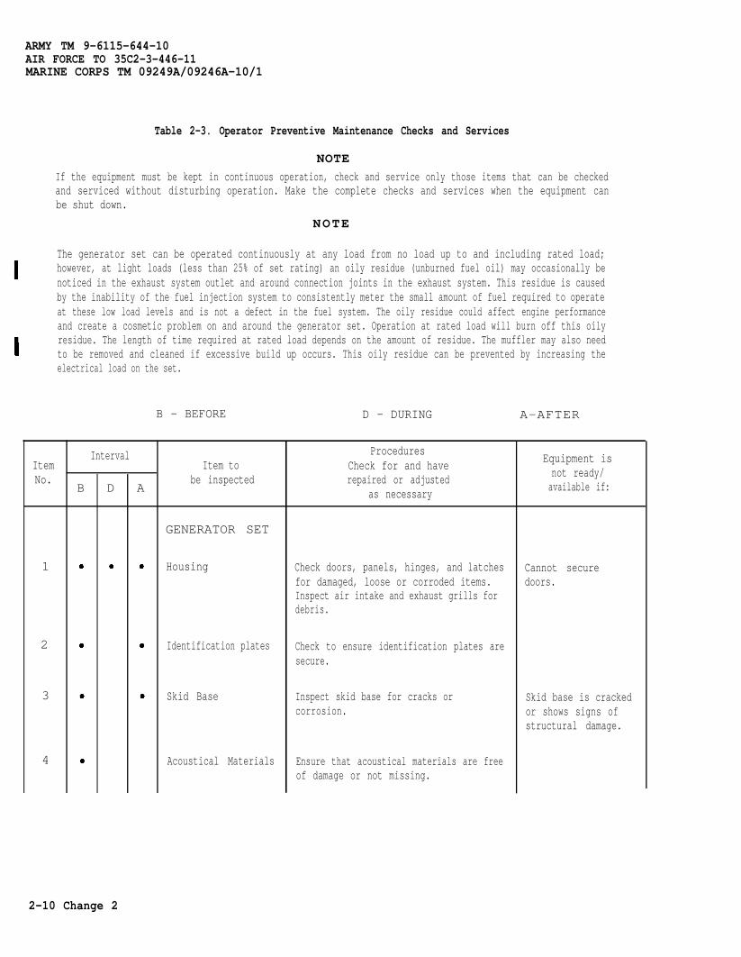
Table 2-3. Operator Preventive Maintenance Checks and Services
NOTEIf the equipment must be kept in continuous operation, check and service only those items that can be checkedand serviced without disturbing operation. Make the complete checks and services when the equipment canbe shut down.
NOTE
The generator set can be operated continuously at any load from no load up to and including rated load;however, at light loads (less than 25% of set rating) an oily residue (unburned fuel oil) may occasionally benoticed in the exhaust system outlet and around connection joints in the exhaust system. This residue is causedby the inability of the fuel injection system to consistently meter the small amount of fuel required to operateat these low load levels and is not a defect in the fuel system. The oily residue could affect engine performanceand create a cosmetic problem on and around the generator set. Operation at rated load will burn off this oilyresidue. The length of time required at rated load depends on the amount of residue. The muffler may also needto be removed and cleaned if excessive build up occurs. This oily residue can be prevented by increasing theelectrical load on the set.
B - BEFORE D - DURING A-AFTER
ItemNo.
Interval
B D A
Item tobe inspected
GENERATOR SET
1
2
3
4
Housing
Identification plates
Skid Base
Acoustical Materials
ProceduresCheck for and haverepaired or adjusted
as necessary
Check doors, panels, hinges, and latchesfor damaged, loose or corroded items.Inspect air intake and exhaust grills fordebris.
Check to ensure identification plates aresecure.
Inspect skid base for cracks orcorrosion.
Ensure that acoustical materials are freeof damage or not missing.
Equipment isnot ready/available if:
Cannot securedoors.
Skid base is crackedor shows signs ofstructural damage.
2-10 Change 2

ItemNo.
B
5
6
7
ARMY TM 9-6115-644-10AIR FORCE TO 35C2-3-446-11
MARINE CORPS TM 09249A/09246A-10/1
Table 2-3. Operator Preventive Maintenance Checks and Services - Continued
B - BEFORE D - DURING A - A F T E R
Interval
D A
Item tobe inspected
ENGINECOMPARTMENT
Engine Assembly
Fuel System
Fuel Filter/ WaterSeparator
Procedures
Check for and have
repaired or adjusted
as necessary
With any access door open, the noise
level of this generator set when
operating could cause hearing damage.
Hearing protection must be worn when
working near the generator set while
running.
The fuels in this generator set are highly
explosive. DO NOT smoke or use open
flame when performing maintenance.
Flames and explosion can occur
resulting in severe personal injury or
death.
Check for loose damaged or missing
hardware.
Inspect fuel system for leaks, damaged,loose or missing parts.
Inspect fuel filter/ water separator forleaks, proper mounting, cracks, damage,or missing parts.
Drain water from fuel filter/ waterseparator.
Equipment isnot read y/available if:
Any fuel leaks,damaged, loose ormissing parts.
Any fuel leaks.
Fuel filter/ waterseparator notdrained.
Change 1 2-11

ARMY TM 9-6115-64410AIR FORCE TO 35C2-3-446-11MARINE CORPS TM 09249A/09246A-10/1
Table 2-3. Operator Preventive Maintenance Checks and Services - Continued
ItemNo. be inspected
B D A
8
9
10
11
B - BEFORE
IntervalItem to
Ether Start System
Lubrication System
COOLING SYSTEM
Radiator
Hoses
D - DURING A - A F T E R
ProceduresCheck for and haverepaired or adjusted
as necessary
Check for deteriorated, loose or missingparts.
Inspect lubrications system for leaks,damaged, loose or missing parts.
Check engine oil level.
Check engine oil for contamination.
Cooling system operates at hightemperatures. Personal injury or deathfrom burns or scalding can result fromcontact with high pressure steam and/orliquid.
Check radiator for leaks, damage ormissing parts.
Check hoses for leaks or cracks.
Equipment isnot ready/available if
Oil leaks at ClassIII. Damaged, looseor missing parts.
Oil level is belowoil level.
Engine oil showssigns ofcontamination.
Class III leaks.Radiator capmissing.
Class III leaks.
2-12 Change 1

ItemNo. B
12
13
14
15
16
ARMY TM 9-6115-644-10AIR FORCE TO 35C2-3-446-11
MARINE CORPS TM 09249A/09246A-10/1
Table 2-3. Operator Preventive Maintenance Checks and Services - Continued
B - BEFORE D - DURING A - AFTER
Interval
D A
Item tobe inspected
Cooling Fan
Fan Belts
Over-flow Bottle
Exhaust System
Air CleanerAssembly
ProceduresCheck for and haverepaired or adjusted
as necessary
Check fan for damage or looseness.
Check for unusual noise being emittedfrom fan area.
Inspect belts for cracks, fraying andlooseness.
Check over-flow bottle for leaks ormissing parts.
Check coolant level
Check muffler for leaks and exhaustsystem for corrosion, damaged, ormissing parts.
Inspect air cleaner assembly and pipingfor loose or damaged connections.Check restriction indicator for cloggedelement.
Equipment isnot read y/available if
Cooling fan isdamaged or loose.
Broken belt(s).
Class III leaks
Coolant level is atcold line.
Muffler or exhaustsystem damaged orleaking.
Clogged element isindicated or pipingand connections areloose.
Change 1 2-13

ARMY TM 9-6115-644-10AIR FORCE TO 35C2-3-446-11MARINE CORPS TM 09249A/09246A-10/1
Table 2-3. Operator Preventive Maintenance Checks and Services - Continued
ItemNo.
17
18
19
Interval
B D A
B - BEFORE
Item tobe inspected
Batteries
Battery Cables
Output BoxAssembly
D - DURING A - A F T E R
ProceduresCheck for and haverepaired or adjusted
as necessary
Battery acid can cause burns tounprotected skin.
Batteries give off flammable gas. Donot smoke or use open flame whenperforming maintenance. Flames andexplosion could result in personal injuryor death.
Check electrolyte level.
Inspect cables and connectors forcorrosion, loose, damaged or missingparts.
High voltage is produced when thisgenerator set is in operation. Improperoperation could result in personal injuryor death.
Check for loose or damaged wiring orcables.
Check output terminals for damaged ormissing hardware.
Equipment isnot ready/available if
Cables are loose,damaged or missing.
Loose or damagedwiring or cables.
Damaged or missinghardware.
2-14 Change 1

ItemNo.
Interval
B D A
20
21
22
23
ARMY TM 9-6115-644-10AIR FORCE TO 35C2-3-446-11
MARINE CORPS TM 092494/09246A-10/1
Table 2-3. Operator Preventive Maintenance Checks and Services - ContinuedB - BEFORE D-DURING A-AFTER
Item tobe inspected
CONTROL BOXASSEMBLY
Indicators andControls
Control Box Harness
Parallel Cable
Ground Rod Cableand Connection
ProceduresCheck for and haverepaired or adjusted
as necessary
Check all indicators and controls fordamaged or missing parts.
Ensure all indicators are operatingproperly.
Check for loose or damaged wiring.
If required for generator set operation,inspect parallel cable for damage.
ENSURE generator set is properlygrounded prior to starting. Otherwiseserious injury or death could result byelectrocution.
Inspect ground rod and cable for looseconnections, breaks, damage andcorrosion.
Equipment isnot ready/available if:
Indicators orcontrols damaged ormissing.
Frequency or ACVoltmeterinoperative.
Loose or damagedwires.
Cable is missing ordamaged.
Change 1 2-15

ARMY TM 9-6115-644-10AIR FORCE TO 35C2-3-446-11MARINE CORPS TM 09249A/09246A-10/1
SECTION III. OPERATION UNDER USUAL CONDITIONS
2-6 GENERAL.This section provides information and guidance for gener-ator set operation under normal conditions, refer to FM20-31.
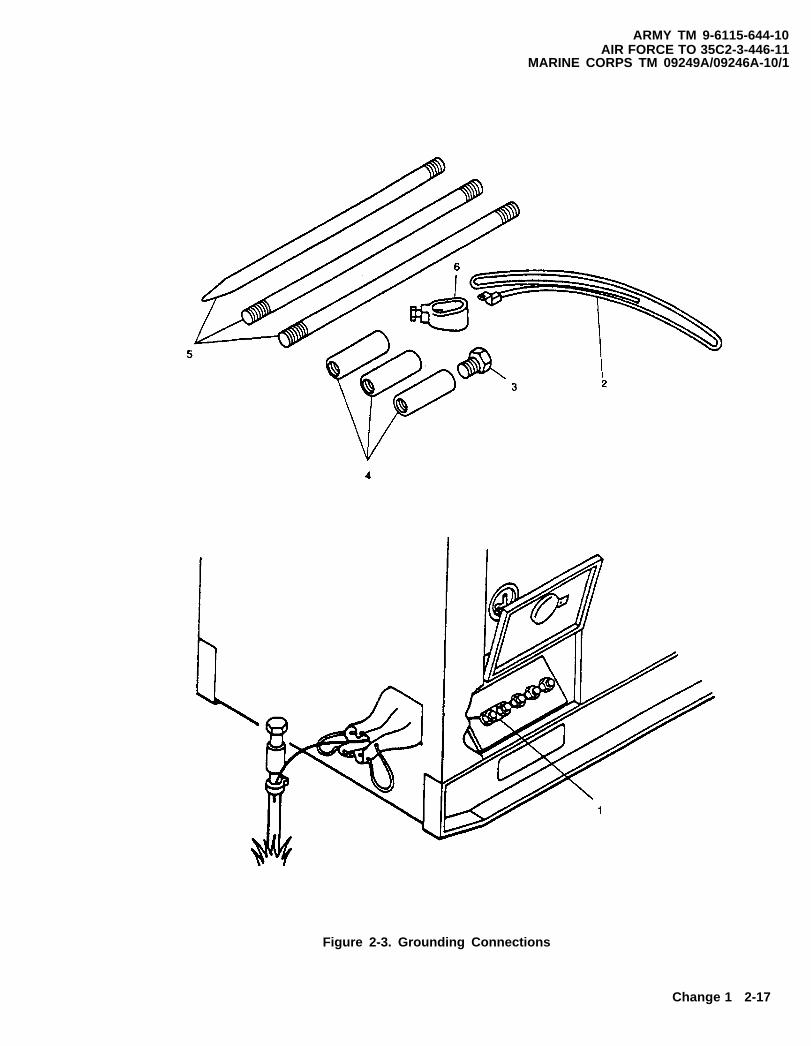
2-7 ASSEMBLY AND PREPARATION FOR USE.2-7.1 Installation of Grounding Rod.
Do not operate the generator set until it hasbeen connected to a suitable ground. Seriousinjury or death can result from operating an un-grounded generator set.
a. Insert ground cable (2, Figure 2-3) through slot onload output terminal board marked GND (1). Tight-en terminal nut.
b. Connect coupling (5) to ground rod (4) and screwdriving stud (3) into coupling (5). Make sure thatdriving stud (3) seats on ground rod (4).
c. Drive ground rod into ground until coupling is justabove surface.
d. Remove driving stud and install another section ofground rod.
e. Install another coupling (5) and driving stud (3).Drive ground rod down until new coupling is justabove ground surface.
f. Repeat steps d and e until ground rod has been driv-en eight feet or deeper, providing an effectiveground.
g. Connect clamp (6) and ground cable (2) to groundrod (4) and tighten clamp screw.
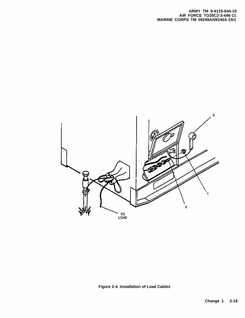
2-7.2 Installation of Load Cables.
Never attempt to connect or disconnect loadcables while the generator set is running. Fail-ure to observe this warning could result in se-vere personal injury or death by electrocution.
Do not connect the load cables to the conven-ience receptacle. Failure to observe this cautioncan result in damage to the generator set.
a. Shutdown generator set.
b. Select required output terminals from Table 2-4.
c. Open output load terminal board door.
2-16 Change 2
ARMY TM 9-6115-644-10AIR FORCE TO 35C2-3-446-11
MARINE CORPS TM 09249A/09246A-10/1
Figure 2-3. Grounding Connections
Change 1 2-17

ARMY TM 9-6115-644-10AIR FORCE TO 35C2-3-446-11MARINE CORPS TM 09249A/09246A-10/1
d. Using terminal nut wrench (3, Figure 2-4) loosenterminal nuts (1) on terminals (2) selected in Step b.
e. Insert ends of load cables through load cable en-trance box. Insert ends of cables into slots of loadterminal studs (2).
f. Tighten load terminal nuts (1).
g. Secure wrench (3) in bracket inside load terminalboard door, and close door.
When using single phase connections, alwaysattempt to balance loads between terminals (donot connect all loads between one terminal andLO). Failure to observe this caution can resultin damage to generator set.
Table 2-4. Load Terminal, AC Reconnection Board and AM-VM Transfer Switch Selection
RECONNEC-TION
BOARDPOSITION
120/208
240/416
TERMINALS
AM-VMTRANSFER
SWITCHPOSITION
VOLTAGEREADING
CURRENTREADING
(TERMINAL)
L1, L2, L3, L0 3PHASE.(SINGLE PHASELOADS CAN BESERVED USING ANYTERMINAL TO L0)
L1-L0L2-L0L3-L0L1-L2L2-L3L3-L1
120 VOLTS120 VOLTS120 VOLTS208 VOLTS208 VOLTS208 VOLTS
L1L2L3
NONENONENONE
L1, L2, L3, L0 3PHASE.(SINGLE PHASELOADS CAN BESERVED USING ANYTERMINAL TO L0)
L 1 -L0L2-L0L3-L0L1-L2L2-L3L3-L1
240 VOLTS240 VOLTS240 VOLTS416 VOLTS416 VOLTS416 VOLTS
L1L2L3
NONENONENONE
2-18 Change 1
ARMY TM 9-6115-644-10AIR FORCE TO35C2-3-446-11
MARINE CORPS TM 09249A/09246A-10/1
Figure 2-4. Installation of Load Cables
Change 1 2-19

ARMY TM 9-6115-644-10AIR FORCE TO 35C2-3-446-11MARINE CORPS TM 09249A/09246A-10/1
2-8 INITIAL ADJUSTMENTS, DAILY CHECKS
AND SELF TEST.
2-8.1 Perform all before (B) PMCS, refer to Table 2-3.
2-8.2 Initial Adjustments.
a.
b.
c .
d.
e.
Place DEAD CRANK switch in NORMAL posi-tion.
Push DC CONTROL POWER circuit breaker in.
Place FREQUENCY SELECT switch to requiredposition (MEP-806A).
Ensure voltage reconnection terminal board is posi-tioned to match voltage requirements. If voltagereconnection terminal board must be changed,notify next higher maintenance level.
Place AM-VM transfer switch in a position corre-sponding to output terminal load connections, referto Table 2-4.
f. Place PARALLEL UNIT switch in UNIT position.
g. Pull out EMERGENCY STOP switch.
2-8.3 Self test.
a.
b.
c .
d.
Place MASTER SWITCH to PRIME AND RUNposition.
Push PRESS TO TEST pushbutton on malfunctionindicator panel. Ensure all indicator lights are lit.When PRESS TO TEST pushbutton is released, alllights should go out.
Press BATTLE SHORT press to test light on thecontrol panel assembly. Ensure indicator light is lit.When press to test light is released, light should goout.
Press AC CIRCUIT INTERRUPTER press to testlight on the control panel assembly. Ensure indica-tor light is lit. When press to test light is releasedlight should go out.
2-20 Change 1

2-9 OPERATING PROCEDURE.
High voltage is produced when generator set isin operation. Improper operation could resultin personal injury or death.
Exhaust discharge contains deadly gases. Donot operate the generator set in enclosed areasunless exhaust discharge is properly ventedoutside. Severe personal injury or death due tocarbon monoxide poisoning could result.
NOTE
If generator set is to be operated in parallel withanother unit, refer to PARALLEL UNIT OP-ERATION, paragraph 2-10.
ARMY TM 9-6115-644-10AIR FORCE TO 35C2-3-446-11
MARINE CORPS TM 09249A/09246A-10/1
2-9.1 Starting Procedure.
Never attempt to start the generator set if it hasnot been properly grounded. Failure to observethis warning could result in serious injury ordeath by electrocution.
Do not crank engine in excess of fifteen se-conds. Allow starter to cool at least fifteen se-conds between attempted starts. Failure toobserve this caution could result in damage tothe starter.
NOTE
At temperatures below 40°F (4°C) it may be neces-sary to use the cold weather starting aid.
NOTE
Ensure all generator set access doors, except con-trol panel access door, are closed.
Change 1 2-21

ARMY TM 9-6115-644-10AIR FORCE TO 35C2-3-446-11MARINE CORPS TM 09249A/09246A-10/1
a.
b.
c .
d.
e.
f .
Rotate MASTER SWITCH to START position.
In cold weather conditions, push ETHER switch toON position as required, until engine accelerates togoverned speed.
Hold MASTER SWITCH in START position untiloil pressure reaches at least 25 psi (172 kPa), voltagehas increased to its approximate rated value, andengine has reached stable operating speed.
Release MASTER SWITCH to PRIME AND RUNposition.
If operating with an auxiliary fuel source, rotateMASTER SWITCH to PRIME AND RUN AUXFUEL position.
N O T E
Warm up engine without load far five minutes. (Ifrequired, load can be applied immediately).
Check COOLANT TEMP [170-200°F (77-93°C)]and OIL PRESSURE [25-60 psi (172-414 kPa)]indicators for normal readings.
g.
h.
i .
j .
k .
l .
Turn VOLTAGE and FREQUENCY adjust poten-tiometers to required values for voltage and frequen-cy.
Press GROUND FAULT CIRCUIT INTERRUPT-ER TEST pushbutton. Ensure indicator window isclear. Press RESET pushbutton and ensure indicatoris red.
Place AC CIRCUIT INTERRUPTER switch toCLOSED position.
Ensure voltage and frequency are still at rated val-ues. Adjust if necessary.
Rotate AM-VM transfer switch to each phase posi-tion while observing ammeter (PERCENT RATEDCURRENT). If more than rated load is indicated inany phase, reduce load.
Check kilowattmeter (PERCENT POWER) . If in-dication is more than 100 percent rated load, reduceload.
2-22 Change 1

With any access door open, the noise level ofthis generator set when operating could causehearing damage. Hearing protection must beworn when working near the generator setwhile running.
m. Perform all DURING (D) OPERATION PMCS re-quirements in accordance with Table 2-3.
2-9.2 Stopping Procedure.
a.
b .
c.
d.
e.
2-10
Place AC CIRCUIT INTERRUPTER switch inOPEN position.
Allow generator set to operate five minutes with noload applied.
Place MASTER SWITCH in OFF position.
Perform all AFTER (A) OPERATION PMCS re-quirements in accordance with Table 2-3.
Place DEAD CRANK switch in OFF position.
PARALLEL UNIT OPERATION (LOADS H A R I N G
ARMY TM 9-6115-644-10AIR FORCE TO 35C2-3-446-11
MARINE CORPS TM 09249A/09246A-10/1
Ensure generator sets are the same size and modebefore attempting parallel operation.
2-10.1 General. The following method of parallel op-eration will be used to share the load between two genera-tor sets. Refer to Figure 2-1 for location of operatorcontrols and indicators mentioned below and Figure 2-5for proper paralleling configuration.
2-10.2 Pre-Operation.
a.
Prior to making any connections for parallel opera-tion, ensure that there is no input to the load andthat the generator sets are shut down. Failure to ob-serve this warning can result in injury or death byelectrocution.
Ensure that load requirement is equal or below thecombined rated capacity of the two generator sets.
Change 1 2-23

ARMY TM 9-6115-644-10AIR FORCE TO 35C2-3-446-11MARINE CORPS TM 09249A/09246A-10/1
Figure 2-5. Parallel Operation Setup
2-24 Change 1

Never attempt to start the generator set if it isnot properly grounded. Failure to observe thiswarning could result in serious injury or deathby electrocution.
b. Determine voltage requirements of load and posi-tion voltage reconnection terminal boards of the twogenerator sets to the required voltage connection.E n s u r e F R E Q U E N C Y S E L E C T s w i t c h(MEP805A) for both generators are positioned forthe same load requirements.
c. Identify one generator set as No. 1 and the other asNo. 2.
d. Remove paralleling cable from storage box locatedinside battery compartment access door.
ARMY TM 9-6115-644-10AIR FORCE TO 35C2-3-446-11
MARINE CORPS TM 09249A/09246A-10/1
e. Connect the paralleling cable between the two gen-erator sets. Connect the generator sets to the loadobserving the proper phase polarity.
Do not close the AC CIRCUIT INTERRUPT-ER switch on either of the generator sets, norclose the load contactor at load until specifical-ly directed to do so. Closing any of these de-vices at any other time may severely damageone or both of the generator sets.
2-10.3 Operation.
a. Start each generator set, refer to paragraph 2-9.1.
b. Rotate both VOLTAGE adjust potentiometers to ob-tain the same voltage indication on each set.
Change 1 2-25

ARMY TM 9-6115-644-10AIR FORCE TO 35C2-3-446-11MARINE CORPS TM 09249A/09246A-10/1
c .
d .
e.
f.
Rotate both FREQUENCY adjust potentiometers toobtain the same frequency indication on both sets.Ensure load contactor at load is open.
Position and hold AC CIRCUIT INTERRUPTERswitch, on generator set No. 1, to CLOSED untilindicator lights.
Place the UNIT-PARALLEL switch on both units inPARALLEL position.
If synchronizing lights on generator set No. 2do not glow bright and dark in unison, thephasing is wrong. Shut down generator setsand check that load cables are connected prop-erly. Failure to observe this caution can resultin damage to generator sets.
Observe synchronizing lights on generator set No.2. The lights should be glowing bright and dark inunison.
g.
h .
i .
Adjust frequency of generator set No. 2 until syn-chronizing lights glow bright and dark in unison at2 to 3 second intervals.
Check that load contactor at load is open beforeattempting to place generators on the line.Failure to observe this caution can result indamage to generator sets.
When both synchronizing lights are dark, positionand hold AC CIRCUIT INTERRUPTER switch ofgenerator set No. 2 to the CLOSED position untilindicator lights.
NOTE
The generator sets are now operating in parallelwith no load.
Rotate FREQUENCY adjust potentiometer of gen-erator set No. 1 until kilowattmeter (PERCENTPOWER) indicates approximately “O”.
2-26 Change 1

j. Rotate the VOLTAGE adjust potentiometer of gen-erator set No. 1 until ammeter (PERCENT RATEDCURRENT) reads approximately “O”.
k. Close the load contactor at the load.
NOTE
If the REVERSE POWER indicator of eithergenerator set lights, and the AC Circuit Inter-rupter relay opens, open the load contactor atload and desynchronize the generator sets. (Re-peat the necessary steps d through k above.)
1. Compare ammeter (PERCENT RATED CUR-RENT) readings of both generator sets. If readingsare not within 10 percent, notify next higher level ofmaintenance.
m. Compare kilowattmeter (PERCENT POWER)readings of both generator sets. If readings are notwithin 10 percent, notify next higher level of main-tenance.
2-10.4 Removal from Parallel Operation.
ARMY TM 9-6115-644-10AIR FORCE TO 35C2-3-446-11
MARINE CORPS TM 09249A/09246A-10/1
If necessary to move a generator set which hasbeen operating in parallel with another genera-tor set, shut down remaining generator set con-nected to the load, prior to removing loadcables or ground. Failure to observe this warn-ing can result in injury or death by electrocu-tion.
Prior to removal of generator set from paralleloperation, make sure load does not exceed fullload rating of generator set remaining on theline. Failure to observe this caution can resultin damage to generator set.
a. Position AC CIRCUIT INTERRUPTER switch toOPEN until indicator goes out.
b. Return UNIT-PARALLEL switch to UNIT posi-tion.
Change 1 2-27

ARMY TM 9-6115-644-10AIR FORCE TO 35C2-3-446-11MARINE CORPS TM 09249A/09246A-10/1
c.
2-11
a.
b.
c.
d.
Refer to paragraph 2-9.2 to stop generator set.
PREPARATION FOR MOVEMENT.
Shut down generator set. Refer to paragraph 2-9.2.If generator set is operating in parallel, refer to para-graph 2-10.4.Disconnect load cables.
Disconnect paralleling cable, if used, and store instorage box.
When using auxiliary fuel line, disconnect line,drain excess fuel from line and store line in storagebox.
e.
f.
g.
2-12
Disconnect ground cable and remove ground rods.Store ground rods in holding clips located insidehousing left side generator set. Store cable and cou-plings in storage box.
Secure all generator set access doors and panels.
For assembly and preparation for use, refer to para-graph 2-7.
OPERATINGS INSTRUCTIONS ON PLATES.There are identification and instruction plates on the gen-erator set. Figure 2-6 through Figure 2-20 show the loca-tion and contents of each plate on the generator set.
2-28 Change 1
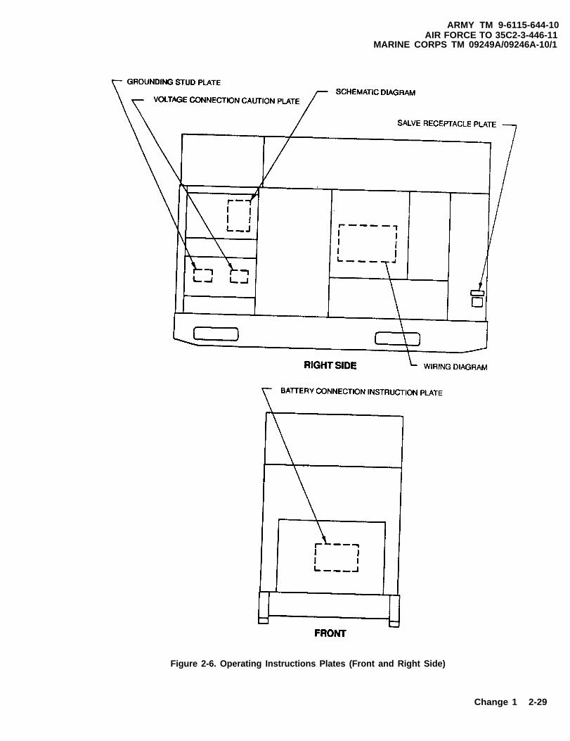
ARMY TM 9-6115-644-10AIR FORCE TO 35C2-3-446-11
MARINE CORPS TM 09249A/09246A-10/1
Figure 2-6. Operating Instructions Plates (Front and Right Side)
Change 1 2-29

ARMY TM 9-6115-644-10AIR FORCE TO 35C2-3-446-11MARINE CORPS TM 09249A/09246A-10/1
Figure 2-7. Operating Instructions Plates (Rear and Left Side)
2-30 Change 1

ARMY TM 9-6115-644-10AIR FORCE TO 35C2-3-446-11
MARINE CORPS TM 09249A/O9246A-10/1
Figure 2-8. Operating Instructions Plate
Change 1 2-31

ARMY TM 9-6115-644-10AIR FORCE TO 35C2-3-446-11MARINE CORPS TM 09249A/09246A-10/1
Figure 2-9. Identification Plates
2-32 Change 2

ARMY TM 9-6115-644-10AIR FORCE TO 35C2-3-446-11
MARINE CORPS TM 09249A/09246A-10/1
Figure 2-10. Set Rating Identification Plate
Figure 2-10.1. Fuel System Diagram Plate
Change 2 2-32.1(2-32.2 blank)

Figure 2-11. Voltage Connection CautionPlate
Figure 2-13. NATO Slave Receptacle Plate
Figure 2-15. Convenience Recpetacle Plate
ARMY TM 9-6115-644-10AIR FORCE TO 35C2-3-446-11
MARINE CORPS TM 09249A/09246A-10/1
Figure 2-12. Grounding Stud Plate
Figure 2-14. Paralleling Receptacle Plate
Figure 2-16. External Fuel Supply Plate
Change 2 2-33
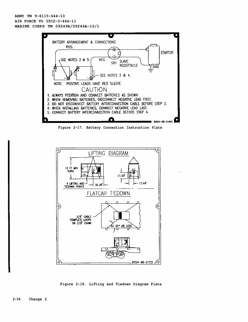
ARMY TM 9-6115-644-10AIR FORCE TO 35C2-3-446-11MARINE CORPS TM 09249A/09246A-10/1
Figure 2-17. Battery Connection Instruction Plate
Figure 2-18. Lifting and Tiedown Diagram Plate
2-34 Change 2

ARMY TM 9-6115-644-10AIR FORCE TO 35C2-3-446-11
MARINE CORPS TM 09249A/09246A-10/1
Figure 2-19. Diagnostics Plate
Figure 2-20. Generator Identification Plate
Change 1 2-35

ARMY TM 9-6115-644-10AIR FORCE TO 35C2-3-446-11MARINE CORPS TM 09249A/09246A-10/1
SECTION IV. OPERATION UNDER UNUSUAL CONDITIONS
2-13 OPERATION IN EXTREME COLD WEATH-ER BELOW-25°F (-31°C)
OPERATION IN EXTREME HEAT ABOVE120°F (48.8°C).
The generator set operates in ambient temperatures as lowas -25°F (-31°C) without special winterizationequipment. To ensure satisfactory operation underextreme cold weather the following steps must betaken:
a .
b.
c .
d.
Avoid contacting metal items with bare skin inextreme cold weather. Failure to observe thiswarning can cause personal injury.
Keep generator set and surrounding area as free ofice and snow as practical.
Keep fuel tank full to protect against moisture, con-densation and accumulation of water.
Ensure that proper grade diesel fuel is used.
Keep batteries free from corrosion and in a wellcharged condition.
2-14
a .
b.
c.
d.
e.
2-15
a.
b .
Check vents and radiator air passages frequently forobstructions.
Check coolant temperature indicator frequently forany indication of overheating.
Allow sufficient space for fuel expansion when fill-ing fuel tank.
Keep generator clean and free of dirt. Clean obstruc-tions from generator intake and outlet screens.
Clean external surface of engine when generator setis not operating.
O P E R A T I O N I N D U S T Y O R S A N D YAREAS.
If possible, provide a shelter for generator set. Useavailable natural barriers to shield generator setfrom blowing dust or sand.
Wet down dusty and sandy surface areas aroundgenerator set frequently if water is available.
2-36 Change 1

c. Keep all access doors closed, as much as possible,to prevent entry of dust and sand into housing as-sembly.
d. Wipe dust and sand frequently from the generatorset external surface and components. Wash exteriorsurfaces frequently with clean water when generatorset is not operating.
e. Service engine air cleaner assembly frequently tocompensate for intake of additional dust or sand.
f. Drain sediment frequently from fuel filter/waterseparator. When servicing fuel tank be careful toprevent dust or sand from entering fuel tank.
g. Change engine oil and oil falter frequently.
h. Store oil and fuel in dust - free containers.
ARMY TM 9-6115-644-10AIR FORCE TO 35C2-3-446-11
MARINE CORPS TM 09249A/09246A-10/1
Failure to remove waterproof material before op-erating generator set could result in equipmentdamage.
a. If possible, provide a shelter for generator set. Covergenerator set with canvas or other waterproof mate-rial when it is not being operated.
b. Provide adequate drainage to prevent water fromaccumulating on operation site.
c. Keep all generator set access doors closed, as muchas possible, to prevent entry of water into housingassembly.
d. Drain water frequently from fuel filter/water separa-tor.
i. Ensure that generator set ground connections arefree of dust and sand and connections are tight be-fore starting the unit. DC voltages are present at generator set electri-
cal components even with generator set shut-down. Avoid grounding yourself whentouching electrical components. Failure to fol-
CONDITIONS. low this warning can result in personal injury.2-16 O P E R A T I O N U N D E R R A I N Y O R H U M I D
Change 1 2-37

ARMY TM 9-6115-644-10AIR FORCE TO 35C2-3-446-11MARINE CORPS TM 09249A/09246A-10/1
e.
f .
2-17
b.
c .
Remove moisture from generator set componentsbefore and after each operating period.
Keep fuel tank full to protect against moisture, con-densation and accumulation of water.
OPERATION IN SALT WATER AREAS.
Failure to remove waterproof material before op-erating generator set could result in equipmentdamage.
a. If possible, provide a shelter for the generator set.Locate generator set so that radiator faces into pre-vailing winds. Use natural barriers or, if possible,construct a barrier to protect generator set from saltwater. Cover generator set with canvas or other wa-terproof material when it is not being operated.
Keep all generator access doors closed as much aspossible, to prevent entry of salt water into housingassembly.
Wash exterior surfaces frequently with clean waterwhen generator set is not operating.
d. Check wiring connections for corrosion and wireinsulation for signs of deterioration.
2-18 OPERATION AT HIGH ALTITUDES.
The generator set will operate at elevations up to 4000 feet(1219.1 meters) above sea level without special adjust-ment or reduction in load. At elevations greater than 4000feet (1219.1 meters) above sea level, the kilowatt rating isreduced approximately 3.5 percent for each additional1000 feet (304.8 meters)
2-19 NATO SLAVE RECEPTACLE START OP-E R A T I O N
2-19.1 General. The NATO slave receptacle can be usedto start the generator set when batteries are discharged.
2-19.2 NATO Slave Emergency Starting Procedure.
a.
b.
c .
Connect one end of NATO slave cable to fullycharged 24 VDC system and other end to dischargedgenerator set’s NATO SLAVE RECEPTACLE.
Start discharged generator set, refer to paragraph2-9.1.
Remove NATO slave cable after generator set starts.
2-38 Change 1

2-20 EMERGENCY STOPPING.
Depressing the EMERGENCY STOP pushbuttonwill stop the generator set.
NOTE
The generator set cannot be restartedwithout resetting the EMERGENCYSTOP pushbutton and turning MASTERSWITCH to OFF position.
2-21 OPERATION USING BATTLE SHORTSWITCH,
Continued operation using the BATTLESHORT switch can result in damage tothe generator set.
NOTE
If any emergency situation requirescontinued operation of the generator set,the BATTLE SHORT switch is used tooverride all protection devices exceptrhe overspeed, short circuit devices, andEMERGENCY STOP function.
NOTE
BATTLE SHORT switch must be OFFto start generator set.
a. Start generator set, if set is not running.Refer to paragraph 2-9.1.
b. Lift cover on BATTLE SHORT switchand position switch to ON.
If the OVERSPEED light on themalfunction indicator panel isilluminated, position the AC circuitinterrupter to the OPEN position untilindicator goes out on each set.
ARMY TM 9-6115-644-10AIR FORCE TO 35C2-3-446-11
MARINE CORPS TM 09249A/09246A-10/1
2-22 OPERATION WHILE CONTAM-INATED.
The generator set will operate in a normal mannerwhen exposed to nuclear, biological or chemical(NBC) contamination. It is capable of beingoperated by personnel wearing NBC clothingwithout special tools or support equipment. Referto FM 3-3, FM 3-4, and FM 3-5.
2-23 USE OF THE CONVENIENCERECEPTACLE.
Power is available when the maincontactor is open. Avoid accidentalcontact. Failure to observe thiswarning can result in severe personalinjury or death by electrocution.
The maximum power rating for theconvenience receptacle is 10 Amps.Continuous operation above 10 Ampscan result in damage to the generatorset.
a. Start the generator set if it is notoperating. Refer to paragraph 2-9.
b. Ensure the load does not exceed themaximum rating.
c. Reset the Ground Fault CircuitInterrupter.
d. Plug appropriate connector intoconvenience receptacle.
Change 2 2-39/(2-40 blank)


ARMY TM 9-6115-644-10AIR FORCE TO 35C2-3-446-11
MARINE CORPS TM 09249A/09246A-10/1
CHAPTER 3
MAINTENANCE INSTRUCTIONS
S E C T I O N I . L U B R I C A T I O N I N S T R U C T I O N S
3-1 LUBRICATION ORDER.
R e f e r t o L O 9 - 6 1 1 5 - 6 4 4 - 1 2f o r l u b r i c a t i o n i n f o r m a t i o n .
SECTION II. TROUBLESHOOTING
3-2 G E N E R A L
T h i s s e c t i o n l i s t s c o m m o nm a l f u n c t i o n s y o u m a y f i n d d u r i n go p e r a t i o n o f t h e g e n e r a t o r s e t .Y o u s h o u l d p e r f o r m t h et e s t s / i n s p e c t i o n s a n d c o r r e c t i v ea c t i o n s i n t h e o r d e r l i s t e d .
T h i s m a n u a l c a n n o t l i s t a l lm a l f u n c t i o n s t h a t m a y o c c u r , n o ra l l t e s t s o r i n s p e c t i o n s a n dc o r r e c t i v e a c t i o n s . I f am a l f u n c t i o n i s n o t l i s t e d o r i sn o t c o r r e c t e d b y l i s t e dc o r r e c t i v e a c t i o n s , n o t i f y y o u rsupervisor.
N O T E
A i r F o r c e a n d M a r i n eC o r p s u s e r s m a yp e r f o r m m a i n t e n a n c eo n l y a s a u t h o r i z e d .
3 - 1

A R M Y T M 9 - 6 1 1 5 - 6 4 4 - 1 0A I R F O R C E T O 3 5 C 2 - 3 - 4 4 6 - 1 1MARINE CORPS TM 09249A/09246A-10 /1
SYMPTOM INDEX
COOLING SYSTEM
COOLANT TEMPERATURE ind ica to ri n d i c a t e s e n g i n e o v e r h e a t i n g . . . . . .
ELECTRICAL SYSTEM
BATTERY CHARGE ammeterShows low or no charge . . . . . . . . .Shows excessive charge . . . . . . . . .
AC VOLTMETER (VOLTS AC)Indicates low voltage . . . . . . . . .I n d i c a t e s c o r r e c t v o l t a g e b u t F r e q u e n c y
meter (HERTZ) is off scale . . . . . .Voltage fluctuates . . . . . . . . . . .
F r e q u e n c y m e t e r ( H E R T Z )F r e q u e n c y f l u c t u a t e s . . . . . . . . . . . . .
AC CIRCUIT INTERRUPTERL i g h t f a i l s t o l i g h t w h e n A C C I R C U I T
I N T E R R U P T E R s w i t c h i s c l o s e d . . . . .L i g h t f a i l s t o c o m e o n g e n e r a t o r
S e t N o . 2 i n p a r a l l e l o p e r a t i o n . . .
SYNCHRONIZING LIGHTSF a i l t o l i g h t . . . . . . . . . . . . . .D o n o t g l o w b r i g h t a n d d a r k i n u n i s o n
o n g e n e r a t o r s e t N o . 2 d u r i n gp a r a l l e l o p e r a t i o n . . . . . . . . . . . .
ENGINE
F a i l s t o c r a n k . . . . . . . . . . . . . . . . . .C r a n k s b u t f a i l s t o s t a r t . . . . . . . . . .S t o p s w h e n M A S T E R S W I T C H i s r e l e a s e d
f r o m S T A R T p o s i t i o n . . . . . . . . . . . . .S tops sudden ly . . . . . . . . . . . . . . . . . . . .R u n s e r r a t i c a l l y o r m i s f i r e s . . . . . . .D o e s n o t d e v e l o p f u l l p o w e r . . . . . . . . . . .Knocks . . . . . . . . . . . . . . . . . . .. . . . . . . . . . . . . . . . . . . .
T r o u b l e s h o o t i n gP r o c e d u r e
P a g e
3 - 7
3 - 83 - 8
3 - 8
3 - 93 - 9
3 - 9
3 - 9
3 - 1 0
3 - 1 0
3 - 1 0
3 - 43 - 4
3 - 43 - 53 - 53 - 53 - 6
3 - 2

ARMY TM 9-6115-644-10AIR FORCE TO 35C2-3-446-11
MARINE CORPS TM 09249A/09246A-10/1
SYMPTOM INDEX - Continued
EXHAUST SYSTEMBlue or white exhaust smoke . . . . . . . . . . . . . . . . . . . . . . . . . . . . . . . . . . . . . . . . . .3-6Black exhaust smoke . . . . . . . . . . . . . . . . . . . . . . . . . . . . . . . . . . . . . . . . . . . . . . . . . . . 3-6
LUBRICATINGS SYSTEMLow oil pressure . . . . . . . . . . . . . . . . . . . . . . . . . . . . . . . . . . . . . . . . . . . . . . . . . . . . . . 3-6
3-3

ARMY TM 9-6115-644-10AIR FORCE TO 35C2-3-446-11MARINE CORPS TM 09249A/09246A-10/1
MALFUNCTION
TEST OR INSPECTION
CORRECTIVE ACTION
Table 3-1. Troubleshooting
1. Engine fails to crank.
Step 1. Check that DEAD CRANK switch is in the NORMAL position.Place switch in NORMAL position.
Step 2. Check that DC CONTROL POWER circuit breaker is energized (in).If DC CONTROL POWER circuit breaker is deenergized (out), go to Step 4.
Step 3. Check that EMERGENCY STOP switch is out.
Step 4. Defect in Engine Starting/Electrical System, Check battery connections.If loose or corroded, notify next higher maintenance level.
2. Engine cranks but fails to start.
Step 1. Cold ambient temperature.If ambient temperature is below 40°F (4°C) turn MASTER SWITCH to START and positionETHER switch to ON, refer to paragraph 2-9.1.
Step 2. Check for dirty air cleaner element.Service air cleaner assembly, refer to paragraph 3-3.3.2.
Step 3. Check for dirty fuel filter/water separator.Service fuel filter/water separator, refer to paragraph 3-3.6.2. If engine still fails to start, notifynext higher maintenance level.
3. Engine starts but stops when MASTER SWITCH is released from START position.
Step 1. Check for proper starting procedure.Hold MASTER SWITCH in START position until 25 psi (172 kPa) is reached, refer to paragraph2-9.1.
Step 2. Check to see if any FAULT INDICATOR lights are lit.NO FUEL light is lit, refer to paragraph 3-3.4,2. If any other lights are lit, notify next highermaintenance level.
3-4 Change 1

A R M Y T M 9 - 6 1 1 5 - 6 4 4 - 1 0A I R F O R C E T O 3 5 C 2 - 3 - 4 4 6 - 1 1
MARINE CORPS TM 09249A/09246A-10 /1
T A B L E 3 - 1 . T R O U B L E S H O O T I N G - C O N T I N U E D
MALFUNCTIONTEST OR INSPECTION
CORRECTIVE ACTION
4 . E n g i n e s t o p s s u d d e n l y .
S t e p 1 . C h e c k t o s e e i f a n y F A U L T I N D I C A T O R l i g h t s a r e l i t .N O F U E L l i g h t i s l i t , r e f e r t o p a r a g r a p h 3 - 3 . 4 . 2 .I f a n y o t h e r l i g h t s a r e l i t , g o t o S t e p 2 .
S t e p 2 . C h e c k t h a t D C C O N T R O L P O W E R c i r c u i t b r e a k e r i se n e r g i z e d ( i n ) .
I f D C C O N T R O L P O W E R c i r c u i t b r e a k e r i s d e e n e r g i z e d( o u t ) , n o t i f y n e x t h i g h e r m a i n t e n a n c e l e v e l .
5 . E n g i n e r u n s e r r a t i c a l l y o r m i s f i r e s .
S t e p 1 . C h e c k f o r d i r t y a i r c l e a n e r e l e m e n t .S e r v i c e a i r c l e a n e r a s s e m b l y , r e f e r t o p a r a g r a p h 3 -3 . 3 . 2 .
S t e p 2 . C h e c k f o r c o n t a m i n a t e d f u e l .S e r v i c e f u e l f i l t e r / w a t e r s e p a r a t o r , r e f e r t op a r a g r a p h 3 - 3 . 6 . 2 .
S t e p 3 . C h e c k f o r i m p r o p e r t y p e o f f u e l .I f i m p r o p e r f u e l i s s u s p e c t e d , r e f e r t o T A B L E 3 - 2 ,n o t i f y n e x t h i g h e r m a i n t e n a n c e l e v e l .
6 . E n g i n e d o e s n o t d e v e l o p f u l l p o w e r .
S t e p 1 . C h e c k f o r d i r t y a i r c l e a n e r e l e m e n t .S e r v i c e a i r c l e a n e r a s s e m b l y , r e f e r t o p a r a g r a p h 3 -3 . 3 . 2 .
S t e p 2 . C h e c k f o r c o n t a m i n a t e d f u e l .S e r v i c e f u e l f i l t e r / w a t e r s e p a r a t o r , r e f e r t op a r a g r a p h 3 - 3 . 6 . 2 .
S t e p 3 . C h e c k f o r r e s t r i c t e d e x h a u s t s y s t e m .M a k e s u r e e x h a u s t o p e n i n g i s f r e e f r o mo b s t r u c t i o n s . I f n o o b s t r u c t i o n s a r e f o u n d , n o t i f yn e x t h i g h e r m a i n t e n a n c e l e v e l .
S t e p 4 . C h e c k f o r i m p r o p e r t y p e o f f u e l .I f i m p r o p e r t y p e o f f u e l i s s u s p e c t e d , r e f e r t oT A B L E 3 - 2 , n o t i f y n e x t h i g h e r m a i n t e n a n c e l e v e l .
3 - 5

A R M Y T M 9 - 6 1 1 5 - 6 4 4 - 1 0A I R F O R C E T O 3 5 C 2 - 3 - 4 4 6 - 1 1MARINE CORPS TM 09249A/09246A-10 /1
T A B L E 3 - 1 . T r o u b l e s h o o t i n g - C o n t i n u e d
MALFUNCTIONTEST OR INSPECTION
CORRECTIVE ACTION
7 . E n g i n e k n o c k s .
S t e p 1 . C h e c k f o r l o w l u b r i c a t i o n o i l l e v e l .I f n e c e s s a r y a d d o i l , r e f e r t o L O 9 - 6 1 1 5 - 6 4 4 - 1 2 .
S t e p 2 . C h e c k f o r l o o s e p a r t s o r f o r e i g n o b j e c t s i n e n g i n ec o m p a r t m e n t .
I f n o l o o s e p a r t s o r f o r e i g n o b j e c t s a r e f o u n d , g ot o S t e p 3 .
S t e p 3 . C h e c k f o r i m p r o p e r t y p e o f f u e l .I f i m p r o p e r t y p e o f f u e l i s s u s p e c t e d , r e f e r t oT A B L E 3 - 2 , n o t i f y n e x t h i g h e r m a i n t e n a n c e l e v e l .
8 . B l u e o r w h i t e e x h a u s t s m o k e .
C h e c k f o r i m p r o p e r t y p e o f f u e l .I f i m p r o p e r t y p e o f f u e l i s s u s p e c t e d , r e f e r t oT A B L E 3 - 2 , n o t i f y n e x t h i g h e r m a i n t e n a n c e l e v e l .
9 . B l a c k e x h a u s t s m o k e .
S t e p 1 . C h e c k f o r i m p r o p e r t y p e o f f u e l .I f i m p r o p e r t y p e o f f u e l i s s u s p e c t e d , r e f e r t oT A B L E 3 - 2 , n o t i f y n e x t h i g h e r m a i n t e n a n c e l e v e l .
S t e p 2 . C h e c k f o r d i r t y a i r c l e a n e r e l e m e n t .S e r v i c e a i r c l e a n e r a s s e m b l y , r e f e r t o p a r a g r a p h 3 -3 . 2 . 2 .
S t e p 3 . C h e c k f o r g e n e r a t o r s e t o v e r l o a d .C h e c k f o r g e n e r a t o r s e t o v e r l o a d b y c h e c k i n g t h eammeter (PERCENT RATED CURRENT) and thek i l o w a t t m e t e r ( P E R C E N T P O W E R ) o n t h e c o n t r o l p a n e la s s e m b l y , r e f e r t o F I G U R E 2 - 1 . I f u n a b l e t oa d j u s t , n o t i f y n e x t h i g h e r m a i n t e n a n c e l e v e l .
1 0 . L o w o i l p r e s s u r e .
S t e p 1 . C h e c k f o r l o w l u b r i c a t i o n o i l l e v e l .I f n e c e s s a r y a d d o i l , r e f e r t o L O 9 - 6 1 1 5 - 6 4 4 - 1 2 .
3 - 6

ARMY TM 9-6115-644-10AIR FORCE TO 35C2-3-446-11
MARINE CORPS TM 09249A/09246A-10/1
Table 3-1. Troubleshooting - Continued
MALFUNCTION
TEST OR INSPECTION
CORRECTIVE ACTION
Step 2.
Step 3.
Step 4.
Step 5.
Check for high coolant temperature, above 200°F (93°C), refer to Figure 2-1.If coolant temperature is high, go to Step 3.
Check coolant level.If low, add coolant, refer to paragraph 3-3.4.2. If full, go to Step 4.
Check for obstruction in air intake system.If obstructions are found, remove debris. If no obstructions are found, go to Step 5.
Check for loose fan belts.If loose, notify next higher maintenance level.
11. COOLANT TEMPERATURE indicator indicates engine overheating.
Step 1. Check for generator set overload. Check for generator set overload by checking the ammeter(PERCENT RATED CURRENT) and the kilowattmeter (PERCENT POWER) on the controlpanel assembly, refer to Figure 2-1.If unable to adjust, notify next higher maintenance level.
Step 2. Check coolant level.If low, add coolant, refer to paragraph 3-3.4.2. If full, go to Step 3.
Step 3. Check for low lubrication oil level.If necessary add oil, refer to LO9-6115-644-12. If full, go to Step 4.
Step 4. Check for obstruction in air intake system.If obstructions are found, remove debris, If no obstructions are found, go to Step 5.
Step 5. Check for loose fan belts.If loose, notify next higher maintenance level.
3 - 7

ARMY TM 9-6115-644-10AIR FORCE TO 35C2-3-446-11MARINE CORPS TM 09249A/09246A-10/1
Table 3-1. Troubleshooting - Continued
MALFUNCTION
TEST OR INSPECTION
CORRECTIVE ACTION
12.
13.
14.
BATTERY CHARGE ammeter shows low or no charge.
Step 1. Check BATTERY CHARGER FUSE.If BATTERY CHARGER FUSE (Figure 2-1) is blown, notify next higher maintenance level.
Step 2. Check fan belts.If loose, notify next higher maintenance level.
Step 3. Check for loose or broken wires. Check for loose or broken wires at the back of the battery charg-ing alternator (Figure 1-2) and BATTERY CHARGER ammeter (Figure 2-1).If wires are loose or broken, notify next higher maintenance level.
BATTERY CHARGE ammeter shows excessive charging after prolonged operation.
Step 1. Check batteries for low electrolyte level.If low refer to paragraph 3-3.2.2. If level is correct, go to step 2.
Step 2. Check battery connections.If loose or corroded, notify next higher maintenance level.
AC voltmeter (VOLTS AC) does not indicate correct voltage.
Step 1. Check that AM-VM transfer switch position corresponds to readings on the AC voltmeter(VOLTS AC), refer to Table 2-4.Set VOLTAGE adjust potentiometer.
Step 2. Check for loose or broken wires at back of AM-VM transfer switch, VOLTAGE adjust potentiom-eter, and AC voltmeter (VOLTS AC).If wires are loose or broken, notify next higher maintenance level.
*U.S. GOVERNMENT PRINTING OFFICE: 1995-655-121/20162
3-8 Change 1

ARMY TM 9-6115-644-10AIR FORCE TO 35C2-3-446-11
MARINE CORPS TM 09249A/09246A-10/1
T A B L E 3 - 1 . T r o u b l e s h o o t i n g - C o n t i n u e d
MALFUNCTIONTEST OR INSPECTION
CORRECTIVE ACTION
15 .
1 6 .
1 7 .
1 8 .
AC voltmeter (VOLTS AC) indicates correct voltage but frequencym e t e r ( H E R T Z ) i s o f f s c a l e .
S t e p 1 . C h e c k F R E Q U E N C Y a d j u s t p o t e n t i o m e t e r .S e t F R E Q U E N C Y a d j u s t p o t e n t i o m e t e r .
S t e p 2 . C h e c k f o r l o o s e o r b r o k e n w i r e s a t b a c k o f F R E Q U E N C Ya d j u s t p o t e n t i o m e t e r .
I f w i r e s a r e l o o s e o r b r o k e n , n o t i f y n e x t h i g h e rm a i n t e n a n c e l e v e l .
A C v o l t m e t e r ( V O L T S A C ) f l u c t u a t e s .
C h e c k b a c k o f A C v o l t m e t e r ( V O L T S A C ) f o r l o o s e o r b r o k e nw i r e s .
I f w i r e s a r e l o o s e o r b r o k e n , n o t i f y n e x t h i g h e rm a i n t e n a n c e l e v e l .
F r e q u e n c y m e t e r ( H E R T Z ) f l u c t u a t e s .
C h e c k b a c k o f f r e q u e n c y m e t e r ( H E R T Z ) f o r l o o s e o r b r o k e nw i r e s .
I f w i r e s a r e l o o s e o r b r o k e n , n o t i f y n e x t h i g h e rm a i n t e n a n c e l e v e l .
A C C I R C U I T I N T E R R U P T E R l i g h t f a i l s t o l i g h t w h e n A C C I R C U I TI N T E R R U P T E R s w i t c h i s c l o s e d .
S t e p 1 . T E S T A C C I R C U I T I N T E R R U P T E R l i g h t b y d e p r e s s i n g .I f l i g h t f a i l s t o l i g h t , r e f e r t o n e x t h i g h e rm a i n t e n a n c e l e v e l .
S t e p 2 . C h e c k l o a d c a b l e s f o r p r o p e r c o n n e c t i o n .F o r p r o p e r c o n n e c t i o n o f t h e l o a d c a b l e s , r e f e r t op a r a g r a p h 2 - 7 . 2 . I f c o r r e c t g o t o S t e p 3 .
S t e p 3 . E n s u r e l o a d d o e s n o t e x c e e d g e n e r a t o r r a t i n g .D e c r e a s e l o a d , i f l o a d i s c o r r e c t , r e f e r t o n e x th i g h e r m a i n t e n a n c e l e v e l .
3 - 9

ARMY TM 9-6115-644-10AIR FORCE TO 35C2-3-446-11MARINE CORPS TM 09249A/09246A-10/1
TABLE 3-1. Troubleshooting - Continued
MALFUNCTIONTEST OR INSPECTION
CORRECTIVE ACTION
19. SYNCHRONIZING LIGHTS fail to light.
Step 1. Check that parallel cable is connected.Connect paralleling cable, refer to paragraph 2-10.2.
Step 2. Check PARALLEL UNIT switch.Place PARALLEL UNIT switch in correct position.
20. SYNCHRONIZING LIGHTS on generator set No. 2 do not glow bright and darkin unison during parallel operation.
Step 1. Check that load cables are connected properly.For proper connection of load cables, refer to paragraph 2-7.2. If properly connected, go to Step 2.
Step 2. Ensure FREQUENCY SELECT switches are in correct positions.Frequency must be the same on both generator sets(MEP-805A).
21. AC CIRCUIT INTERRUPTER light fails to come on generator set No. 2 inparallel operation.
Step 1. Test light by depressing.If light fails to light, notify next higher maintenancelevel. If light comes on, go to Step 2.
Step 2. FREQUENCY adjust potentiometer is not properly adjusted.Set FREQUENCY adjust potentiometer.
22. No voltage at the Convenience Receptacle.
Step 1. Open control panel and inspect circuit breaker on side ofGround Fault Circuit Interrupter device.
If tripped, reset device. Check fuse on black wire ofGround Fault Circuit Interrupter for generator sets,contract number DAAK01-88-D-D082.
Step 2. Check reset button for red band.If red band is visible, push reset button. If GroundFault Circuit Interrupter can not be reset, refer tonext higher maintenance level.
3-10 Change 2
*U.S. GOVERNMENT PRINTING OFFICE: 1997 - 554-024/60018

A R M Y T M 9 - 6 1 1 5 - 6 4 4 - 1 0A I R F O R C E T O 3 5 C 2 - 3 - 4 4 6 - 1 1
MARINE CORPS TM 09249A/09246A-10 /1
SECTION I I I . MAINTENANCE PROCEDURES
3-3 GENERATOR SET INSPECTIONAND SERVICE. WARNING
3 - 3 . 1 I n t r o d u c t i o n . T h i ss e c t i o n c o n t a i n s o p e r a t o rm a i n t e n a n c e p r o c e d u r e s .D e f i c i e n c i e s n o t e d d u r i n gi n s p e c t i o n w h i c h a r e b e y o n d t h em a i n t e n a n c e s c o p e o f t h eo p e r a t o r s h a l l b e r e p o r t e d t on e x t h i g h e r m a i n t e n a n c e l e v e l .
3 - 3 . 2 B a t t e r i e s .
WARNING
B a t t e r y a c i d c a n c a u s eb u r n s t o u n p r o t e c t e ds k i n .
WARNING
B a t t e r i e s g i v e o f ff l a m m a b l e g a s . D o n o ts m o k e o r u s e o p e nf l a m e w h e n p e r f o r m i n gm a i n t e n a n c e . F l a m e sa n d e x p l o s i o n c o u l dr e s u l t i n p e r s o n a li n j u r y o r d e a t h .
3 - 3 . 2 . 1 I n s p e c t i o n .
a . S h u t d o w n g e n e r a t o rs e t , r e f e r t op a r a g r a p h 2 - 9 . 2 .
b . O p e n b a t t e r y a c c e s sd o o r .
door.
C . I n s p e c t f o r d a m a g e db a t t e r y c a s e ,c o r r o s i o n , o r d a m a g e da n d l o o s e c o n n e c t i o n so n t e r m i n a l c a b l e ,a n d d a m a g e d o rm i s s i n g b a t t e r y c a p s .
B a t t e r i e s g i v e o f ff l a m m a b l e g a s . D o n o ts m o k e o r u s e o p e nf l a m e w h e n p e r f o r m i n gm a i n t e n a n c e . F l a m e sa n d e x p l o s i o n c o u l dr e s u l t i n p e r s o n a li n j u r y o r d e a t h .
d . R e m o v e b a t t e r y c a p s .
CAUTION
E l e c t r o l y t e l e v e l m u s tc o v e r b a t t e r y p l a t e si n a l l c e l l s . F a i l u r et o o b s e r v e t h i sc a u t i o n c a n c a u s ed a m a g e t o t h e b a t t e r y .
NOTE
E l e c t r o l y t e l e v e ls h o u l d b e a t b o t t o m o f
e .
f .
g .
h .
e a c h c a p c y l i n d e r .
I n s p e c t e l e c t r o l y t el e v e l .
P e r f o r m s e r v i c ep r o c e d u r e s i fr e q u i r e d .
I n s t a l l b a t t e r y c a p s .
C l o s e b a t t e r y a c c e s s
3 - 3 . 2 . 2 S e r v i c e .
a . S h u t d o w n g e n e r a t o rs e t r e f e r t op a r a g r a p h 2 - 9 . 2 .
3 - 1 1

ARMY TM 9-6115-644-10AIR FORCE TO 35C2-3 -446-11MARINE CORPS TM 09249A/09246A-10/1
b . O p e n b a t t e r y a c c e s sd o o r .
WARNING
B a t t e r i e s g i v e o f ff l a m m a b l e g a s . D o n o ts m o k e o r u s e o p e nf l a m e w h e n p e r f o r m i n gm a i n t e n a n c e . F l a m e sa n d e x p l o s i o n c o u l dr e s u l t i n p e r s o n a li n j u r y o r d e a t h .
c . R e m o v e b a t t e r y c a p s .
NOTE
E l e c t r o l y t e l e v e ls h o u l d b e a t b o t t o m o fe a c h c a p c y l i n d e r .
d .
e .
f .
g .
A d d d i s t i l l e d w a t e rt o e a c h b a t t e r y c e l la s r e q u i r e d .
R e p l a c e b a t t e r y c a p s .
C l o s e b a t t e r y a c c e s sd o o r .
I f n e c e s s a r y c o n t a c tn e x t h i g h e r - l e v e l o fm a i n t e n a n c e t o c l e a no r r e p l a c e b a t t e r i e so r b a t t e r y t e r m i n a l s .
3 - 3 . 3 A i r C l e a n e r A s s e m b l y( F I G U R E 3 - 1 ) .
3 - 3 . 3 . 1 I n s p e c t i o n .
a . S h u t d o w n g e n e r a t o rs e t , r e f e r t op a r a g r a p h 2 - 9 . 2 .
b . O p e n a i r c l e a n e ra c c e s s d o o r ( r e a r o fg e n e r a t o r s e t ) .
c .
d .
e .
f .
O p e n l e f t s i d e e n g i n ec o m p a r t m e n t a c c e s sd o o r .
I n s p e c t a i r c l e a n e rh o u s i n g ( 5 ) f o rd e n t s , c o r r o s i o n ,m i s s i n g h a r d w a r e a n do t h e r d a m a g e .
I n s p e c t r e s t r i c t i o ni n d i c a t o r ( 6 ) f o ri n d i c a t i o n o f ac l o g g e d a i r c l e a n e re l e m e n t ( 4 ) .
C l o s e a i r c l e a n e ra c c e s s d o o r .
F I G U R E 3 - 1 . A i r C l e a n e r E l e m e n tReplacement
3 - 1 2
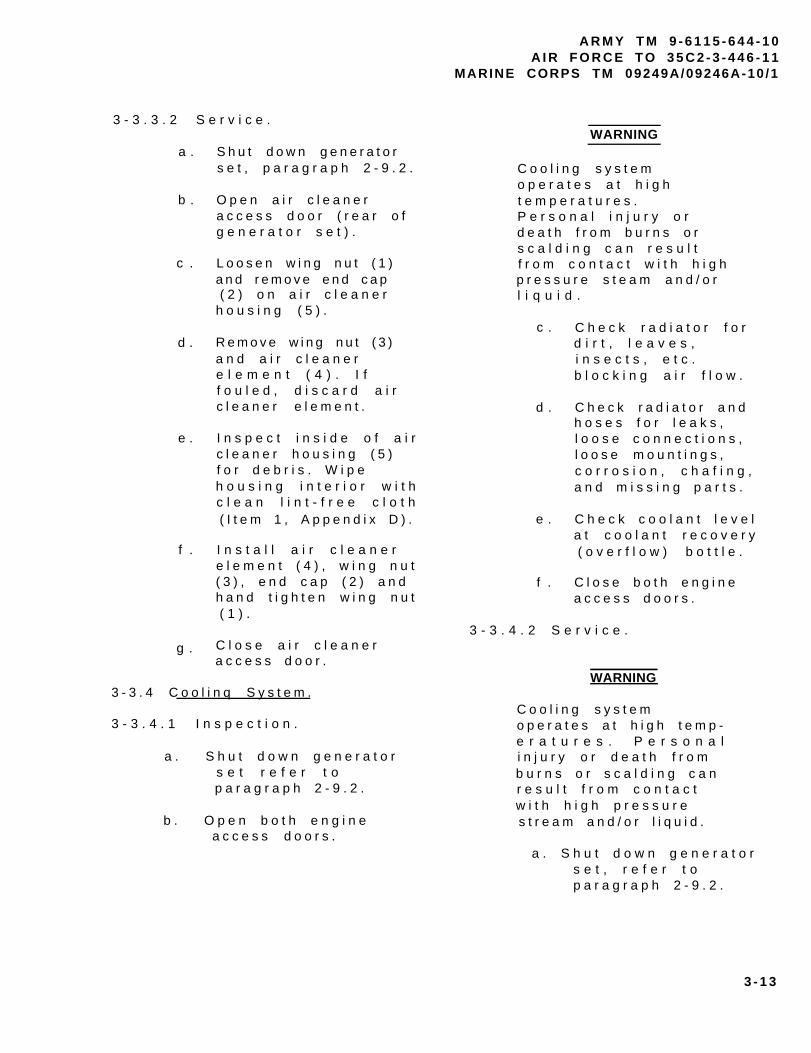
A R M Y T M 9 - 6 1 1 5 - 6 4 4 - 1 0A I R F O R C E T O 3 5 C 2 - 3 - 4 4 6 - 1 1
MARINE CORPS TM 09249A/09246A-10 /1
3 - 3 . 3 . 2 S e r v i c e .WARNING
a .
b .
c .
d .
e .
f .
g .
S h u t d o w n g e n e r a t o rs e t , p a r a g r a p h 2 - 9 . 2 .
O p e n a i r c l e a n e ra c c e s s d o o r ( r e a r o fg e n e r a t o r s e t ) .
L o o s e n w i n g n u t ( 1 )a n d r e m o v e e n d c a p( 2 ) o n a i r c l e a n e r
h o u s i n g ( 5 ) .
R e m o v e w i n g n u t ( 3 )a n d a i r c l e a n e re l e m e n t ( 4 ) . I ff o u l e d , d i s c a r d a i rc l e a n e r e l e m e n t .
I n s p e c t i n s i d e o f a i rc l e a n e r h o u s i n g ( 5 )f o r d e b r i s . W i p eh o u s i n g i n t e r i o r w i t hc l e a n l i n t - f r e e c l o t h( I t e m 1 , A p p e n d i x D ) .
I n s t a l l a i r c l e a n e re l e m e n t ( 4 ) , w i n g n u t( 3 ) , e n d c a p ( 2 ) a n dh a n d t i g h t e n w i n g n u t( 1 ) .
C l o s e a i r c l e a n e r
C o o l i n g s y s t e mo p e r a t e s a t h i g ht e m p e r a t u r e s .P e r s o n a l i n j u r y o rd e a t h f r o m b u r n s o rs c a l d i n g c a n r e s u l tf r o m c o n t a c t w i t h h i g hp r e s s u r e s t e a m a n d / o rl i q u i d .
c .
d .
e .
f .
C h e c k r a d i a t o r f o rd i r t , l e a v e s ,i n s e c t s , e t c .b l o c k i n g a i r f l o w .
C h e c k r a d i a t o r a n dh o s e s f o r l e a k s ,l o o s e c o n n e c t i o n s ,l o o s e m o u n t i n g s ,c o r r o s i o n , c h a f i n g ,a n d m i s s i n g p a r t s .
C h e c k c o o l a n t l e v e la t c o o l a n t r e c o v e r y( o v e r f l o w ) b o t t l e .
C l o s e b o t h e n g i n ea c c e s s d o o r s .
3 - 3 . 4 . 2 S e r v i c e .
a c c e s s d o o r .
3 - 3 . 4 C o o l i n q S y s t e m .
3 - 3 . 4 . 1 I n s p e c t i o n .
a . S h u t d o w n g e n e r a t o rs e t r e f e r t op a r a g r a p h 2 - 9 . 2 .
b . O p e n b o t h e n g i n ea c c e s s d o o r s .
WARNING
C o o l i n g s y s t e mo p e r a t e s a t h i g h t e m p -e r a t u r e s . P e r s o n a li n j u r y o r d e a t h f r o mb u r n s o r s c a l d i n g c a nr e s u l t f r o m c o n t a c tw i t h h i g h p r e s s u r es t r e a m a n d / o r l i q u i d .
a . S h u t d o w n g e n e r a t o rs e t , r e f e r t op a r a g r a p h 2 - 9 . 2 .
3 - 1 3

A R M Y T M 9 - 6 1 1 5 - 6 4 4 - 1 0A I R F O R C E T O 3 5 C 2 - 3 - 4 4 6 - 1 1MARINE CORPS TM 09249A/09246A-10 /1
T A B L E 3 - 2 . C o o l a n t
COOLANT
AMBIENT RADIATORTEMPERATURE COOLANT RATIO
+ 4 0 ° F T O + 1 2 0 ° F Water : MIL -A-53009(+4°C TO +49°C) I N H I B I T O R , 3 5 : 1
CORROSION
- 2 5 ° F T O + 1 2 0 ° F Water : MIL -A-46153( - 3 2 ° C T O + 4 9 ° C ) ANTIFREEZE 1 :1
- 2 5 ° F T O + 1 2 0 ° F M I L - A - 1 1 7 5 5( - 3 2 ° C T O + 4 9 ° C ) ANTIFREEZE NA
b .
c .
d .
e .
f .
O p e n r i g h t s i d e 3 - 3 . 5 F u e l T a n k .e n g i n e a c c e s s d o o r .
3 - 3 . 5 . 1 I n s p e c t i o n .R e m o v e c a p o n c o o l a n tr e c o v e r y ( o v e r f l o w )b o t t l e .
F i l l c o o l a n t r e c o v e r y( o v e r f l o w ) b o t t l e t o
H O T l i n e i f c o o l a n ti s h o t o r t o C O L Dl i n e i f c o o l a n t i sc o l d w i t h p r o p e rc o o l a n t / a n t i f r e e z e i na c c o r d a n c e w i t h T A B L E3 - 2 .
I n s t a l l c o o l a n tr e c o v e r y ( o v e r f l o w )b o t t l e c a p .
C l o s e r i g h t s i d ee n g i n e a c c e s s d o o r .
a. Place MASTER SWITCHi n P R I M E & R U N o rPRIME & RUN AUX FUELp o s i t i o n .
b . C h e c k f u e l l e v e l b yo b s e r v i n g F U E L L E V E Li n d i c a t o r .
c . R e m o v e f u e l c a p a n de n s u r e s t r a i n e r i sf r e e o f d i r t a n do t h e r f o r e i g nm a t e r i a l .
3 - 1 4

A R M Y T M 9 - 6 1 1 5 - 6 4 4 - 1 0A I R F O R C E T O 3 5 C 2 - 3 - 4 4 6 - 1 1
MARINE CORPS TM 09249A/09246A-10 /1
T A B L E 3 - 3 . D i e s e l F u e l
FUEL
AMBIENT D I E S E LTEMPERATURE FUEL
+ 2 0 ° F T O + 1 2 0 ° F W - F - 8 0 0 G R A D E D F - 2( - 7 ° C T O + 4 9 ° C ) J P 4 , J P 5 , J P 8
W - F - 8 0 0 G R A D E D F - 10 ° F T O + 2 0 ° F
( - 1 7 ° C T O + 7 ° C ) I J P 4 , J P 5 , J P 8
- 2 5 ° F T O 0 ° F( - 3 2 ° C T O - 1 7 ° C )
VV-F-800 GRADE DF-1
- 2 5 ° F T O 0 ° F( - 3 2 ° C T O - 1 7 ° C )
V V - F - 8 0 0 G R A D E D F - A
3 - 3 . 5 . 2 S e r v i c e . c . R e m o v e f u e l s t r a i n e r ,c l e a n a s n e c e s s a r y ,a n d r e i n s t a l l .
WARNING
T h e f u e l s i n t h i sg e n e r a t o r s e t a r eh i g h l y e x p l o s i v e . D ON O T s m o k e o r u s e o p e nf l a m e w h e n p e r f o r m i n gm a i n t e n a n c e . F l a m e sa n d e x p l o s i o n c a no c c u r r e s u l t i n g i ns e v e r e p e r s o n a l i n j u r yo r d e a t h .
CAUTION
U s e o n l y s p e c i f i e d
NOTE
F u e l t a n k h o l d s 2 3g a l l o n s ( 8 7 . 1 l i t e r s ) .
d . A d d d i e s e l f u e l t of u e l t a n k .
e . I n s t a l l f u e l c a p .
3 - 3 . 6 F u e l F i l t e r / W a t e rS e p a r a t o r ( F I G U R E 3 - 2 ) .
3 - 3 . 6 . 1 I n s p e c t i o n .d i e s e l f u e l t o s e r v i c et h e f u e l t a n k R e f e r .t o T A B L E 3 - 3 .O t h e r w i s e , e q u i p m e n td a m a g e c o u l d r e s u l t .
a . S h u t d o w n g e n e r a t o rs e t , r e f e r t op a r a g r a p h 2 - 9 . 2 .
b . R e m o v e f u e l c a p .
a . S h u t d o w n g e n e r a t o rs e t , r e f e r t op a r a g r a p h 2 - 9 . 2 .
b . O p e n r i g h t s i d ee n g i n e a c c e s s d o o r .
3 - 1 5

A R M Y T M 9 - 6 1 1 5 - 6 4 4 - 1 0A I R F O R C E T O 3 5 C 2 - 3 - 4 4 6 - 1 1MARINE CORPS TM 09249A/09246A-10 /1
F I G U R E 3 - 2 . D r a i n i n g F u e lF i l t e r / W a t e r S e p a r a t o r
d . C l o s e e n g i n e a c c e s sd o o r .
3 - 3 . 6 . 2 S e r v i c e .
a .
b .
c .
d .
e .
S h u t d o w n g e n e r a t o rs e t , r e f e r t op a r a g r a p h 2 - 9 . 2 .
O p e n r i g h t s i d ee n g i n e a c c e s s d o o r .
O p e n f u e l d r a i n c o c k( 2 ) a n d a i r v e n t ( 1 )o n f u e l f i l t e r / w a t e rs e p a r a t o r a s s e m b l ya n d d r a i n a n ys e d i m e n t a n d w a t e ri n t o a s u i t a b l ec o n t a i n e r .
C l o s e d r a i n c o c k ( 2 )a n d a i r v e n t ( 1 ) .
C l o s e r i g h t s i d ee n g i n e a c c e s s d o o r .
3 - 3 . 7 L u b r i c a t i o n S y s t e m .
3 - 3 . 7 . 1 I n s p e c t i o n .
a .
b .
c .
d .
S h u t d o w n g e n e r a t o rs e t , r e f e r t op a r a g r a p h 2 - 9 . 2 .
O p e n b o t h e n g i n ea c c e s s d o o r s .
I n s p e c t e n g i n ea s s e m b l y f o r o i ll e a k s .
C h e c k f o r d a m a g e ,p r o p e r m o u n t i n g , o rm i s s i n g p a r t s .
c . I n s p e c t f u e lf i l t e r / w a t e rs e p a r a t o r a s s e m b l yf o r p r o p e r m o u n t i n g ,c r a c k s , d e n t s , l e a k s ,l o o s e f u e l l i n e s a n do t h e r d a m a g e .
3 - 1 6

CAUTION
T h e d i p s t i c k i s m a r k e ds o t h a t t h e c r a n k c a s eo i l c a n b e c h e c k e dw h i l e e n g i n e i ss t o p p e d o r r u n n i n g .A l w a y s m a k e s u r ec o r r e c t s i d e o fd i p s t i c k i s c h e c k e d .R e m o v e o i l f i l l e r c a pw h e n c h e c k i n g o i l w i t he n g i n e r u n n i n g .
e . C h e c k e n g i n ec r a n k c a s e o i l l e v e l .R e f e r t oL O 9 - 6 1 1 5 - 6 4 4 - 1 2 .
f . C l o s e b o t h e n g i n ea c c e s s d o o r s .
A R M Y T M 9 - 6 1 1 5 - 6 4 4 - 1 0A I R F O R C E T O 3 5 C 2 - 3 - 4 4 6 - 1 1
MARINE CORPS TM 09249A/09246A-10 /1
3 - 3 . 7 . 2 S e r v i c e .
a .
b .
c .
d .
e .
f .
S h u t d o w n g e n e r a t o rs e t , r e f e r t op a r a g r a p h 2 - 9 . 2 .
O p e n r i g h t e n g i n ea c c e s s d o o r .
R e m o v e o i l f i l l e rc a p .
A d d o i l t o e n g i n ec r a n k c a s e . R e f e r t oL O 9 - 6 1 1 5 - 6 4 4 - 1 2 .
I n s t a l l o i l f i l l e rc a p .
C l o s e r i g h t s i d ee n g i n e a c c e s s d o o r .
3-17/(3-18 blank)


APPENDIX A
REFERENCES
A - 1 S C O P E .
T h i s a p p e n d i x l i s t s a l lf o r m s , f i e l d m a n u a l s , t e c h n i c a lm a n u a l s a n d m i s c e l l a n e o u sp u b l i c a t i o n s r e f e r e n c e d i n t h i sm a n u a l .
A - 2 F O R M S .
E q u i p m e n t C o n t r o lLog . . . . . . . . . . . . . .DA Form 2408-9
Q u a l i t y D e f i c i e n c yReport . . . . . . . . . . . . . . . . . .SF368
E q u i p m e n t I n s p e c t i o n a n dM a i n t e n a n c eWorksheet . . . . . . . . ..DA Form 2404
R e c o m m e n d e d C h a n g e s t oP u b l i c a t i o n s a n d B l a n kForms . . . . . . . . . . . ..DA Form 2028
R e c o m m e n d e d C h a n g e s t o E q u i p m e n tPublications. . . . . . . . . . ...DA Form 2028-2
R e p o r t i n g E r r o r s a n dRecommending Improvements toT e c h n i c a lPublications . . . . . . . NAVMC 10772
A - 3 F I E L D M A N U A L S .
Elec t r i c Power Genera t ion in theField . . . . . . . . . . . . . . . .FM 20-31
First Aid . . . . . . . . . . . .FM 21-11
A R M Y T M 9 - 6 1 1 5 - 6 4 4 - 1 0A I R F O R C E T O 3 5 C 2 - 3 - 4 4 6 - 1 1
MARINE CORPS TM 09249A/09246A-10/1
N B C C o n t a m i n a t i o nAvoidance . . . . . . . . . . . . . . .FM 3-3
NBC Protect ion . . . . . . . . . .FM 3-4NBC Decontaminat ion . . . . . . .FM 3-5
A-4 TECHNICAL MANUALS.
Marine Corps Forms.. . . . . . . TM 4700-15/1
A-5 MISCELLANEOUS PUBLICATIONS.
T h e A r m y M a i n t e n a n c e M a n a g e m e n tSys tem (TAMMS) . . DA PAM 738-750
A i r F o r c e M a i n t e n a n c e F o r m s a n dRecords . . . . . . . . . . . . . .AFR 66-1
L u b r i c a t i o nOrder. . . . . . . . . . . . . . . .LO 9-6115-644-12
W a r r a n t y T e c h n i c a lBulletin. . . . . . . . . . . . . .TB 9-6115-644-24
M i l i t a r y S t a n d a r dA b b r e v i a t i o n s . . . . . . . M I L - S T D - 1 2
Q u a l i t y D e f i c i e n c yManual . . . . . . . . . . . . ..MCO 4855.10
A-1 / (A-2 b lank)

A R M Y T M 9 - 6 1 1 5 - 6 4 4 - 1 0A I R F O R C E T O 3 5 C 2 - 3 - 4 4 6 - 1 1
MARINE CORPS TM 09249A/09246A-10 /1
APPENDIX B
COMPONENTS OF END ITEM AND BASIC ISSUE ITEMS LISTS
B - 1 S C O P E .
T h i s a p p e n d i x l i s t sc o m p o n e n t s o f e n d i t e m a n d b a s i ci s s u e i t e m s f o r t h e g e n e r a t o rs e t t o h e l p y o u i n v e n t o r y i t e m sr e q u i r e d f o r s a f e a n d e f f i c i e n to p e r a t i o n .
B - 2 G E N E R A L .
T h e C o m p o n e n t s o f E n d I t e ma n d B a s i c I s s u e I t e m s L i s t s a r ed i v i d e d i n t o t h e f o l l o w i n gs e c t i o n s :
S e c t i o n I I . C o m p o n e n t so f E n D I t e m ( C O E I ) . T h i sl i s t i n g i s f o r i n f o r m a t i o n a lp u r p o s e s o n l y , a n d i s n o ta u t h o r i t y t o r e q u i s i t i o nr e p l a c t m e n t s . T h e s e i t e m s a r ep a r t o f t h e e n d i t e m , b u t a r er e m o v e d a n d s e p a r a t e l y p a c k a g e df o r t r a n s p o r t a t i o n o r s h i p m e n t .A s p a r t o f t h e e n d i t e m , t h e s ei t e m s m u s t b e w i t h t h e e n d i t e mw h e n e v e r i t i s i s s u e d o rt r a n s f e r r e d b e t w e e n p r o p e r t ya c c o u n t s . l l u s t r a t i o n s a r ef u r n i s h e d t o a s s i s t y o u i ni d e n t i f y i n g t h e i t e m s .
b . S e c t i o n I I I . B a s i cI s s u e I t e m s ( B I I ) . T h e s e a r et h e m i n i m u m e s s e n t i a l i t e m sr e q u i r e d t o p l a c e t h e g e n e r a t o rs e t i n o p e r a t i o n , t o o p e r a t e i t ,a n d t o p e r f o r m e m e r g e n c yr e p a i r s . A l t h o u g h s h i p p e ds e p a r a t e l y p a c k a g e d , B I I m u s t b ew i t h t h e g e n e r a t o r s e t d u r i n go p e r a t i o n a n d w h e n e v e r i t i s
SECTION I. INTRODUCTION
t r a n s f e r r e d b e t w e e n p r o p e r t ya c c o u n t s . T h e i l l u s t r a t i o n sw i l l a s s i s t y o u w i t h h a r d - t o -i d e n t i f y i t e m s . T h i s m a n u a l i sy o u r a u t h o r i t y t or e q u e s t / r e q u i s i t i o n r e p l a c e m e n tB I I , b a s e d o n T O E / M T O Ea u t h o r i z a t i o n o f t h e e n d i t e m .
B-3 EXPLANATION OF COLUMNS.
T h e f o l l o w i n g p r o v i d e s a ne x p l a n a t i o n o f c o l u m n s f o u n d i nt h e t a b u l a r l i s t i n g :
a . C o l u m n ( 1 ) -I l l u s t r a t i o n N u m b e r ( I l l u sN u m b e r ) . T h i s c o l u m n i n d i c a t e st h e n u m b e r o f t h e i l l u s t r a t i o ni n w h i c h t h e i t e m i s s h o w n .
b . C o l u m n ( 2 ) - N a t i o n a lS t o c k N u m b e r . I n d i c a t e s t h eN a t i o n a l S t o c k N u m b e r a s s i g n e dt o t h e i t e m a n d w i l l b e u s e d f o rr e q u i s i t i o n i n g p u r p o s e s .
c . C o l u m n ( 3 ) -D e s c r i p t i o n . I n d i c a t e s t h eF e d e r a l i t e m n a m e a n d , i fr e q u i r e d , a m i n i m u m d e s c r i p t i o nt o i d e n t i f y a n d l o c a t e t h e i t e m .T h e l a s t l i n e f o r e a c h i t e mi n d i c a t e s t h e C o m m e r c i a l a n dG o v e r n m e n t E n t i t y ( C A G E ) c o d e( i n p a r e n t h e s e s ) f o l l o w e d b y t h e
p a r t n u m b e r . U s a b l e o n c o d ei d e n t i f i e s t h e s p e c i f i c t y p e o fg e n e r a t o r s e t ( 5 0 / 6 0 o r 4 0 0 H z )t o w h i c h t h e B I I a p p l i e s .H o w e v e r , t h e r e a r e n o B I I w h i c ha r e s p e c i f i c t o e i t h e r t h e 5 0 / 6 0o r 4 0 0 H z g e n e r a t o r s e t s .
B - 1

A R M Y T M 9 - 6 1 1 5 - 6 4 4 - 1 0A I R F O R C E T O 3 5 C 2 - 3 - 4 4 6 - 1 1MARINE CORPS TM 09249A/09246A-10 /1
APPENDIX B
d . C o l u m n ( 4 ) - U n i t o f e . C o l u m n ( 5 - Q u a n t i t y )M e a s u r e ( U / M ) . I n d i c a t e s t h e r e q u i r e d ( Q t y r e q d ) . I n d i c a t e sm e a s u r e u s e d i n p e r f o r m i n g t h e t h e q u a n t i t y o f t h e i t e ma c t u a l o p e r a t i o n a l / m a i n t e n a n c e a u t h o r i z e d t o b e u s e d w i t h / o nf u n c t i o n . T h i s m e a s u r e i s t h e e q u i p m e n t .e x p r e s s e d b y a t w o - c h a r a c t e ra l p h a b e t i c a l a b b r e v i a t i o n ( e . g . ,ea r i n , p r ) .
SECTION I I . COMPONENTS OF END ITEM LIST
NONE
S E C T I O N I I I . B A S I C I S S U E I T E M S
(1 )I l l u sNumber
1
2
3
( 2 )N a t i o n a l S t o c k
N u m b e r
( 3 ) ( 4 ) ( 5 )Description Usable Q t y
C a g e a n d P a r t N u m b e r O n C o d e U / M r e q d
TECHNICAL MANUAL,T M 9 - 6 1 1 5 - 6 4 4 - 1 0 EA 1
LUBRICATION ORDER,L O 9 - 6 1 1 5 - 6 4 4 - 1 2 EA 1
WARRANTY TECHNICALB U L L E T I N
T B 9 - 6 1 1 5 - 6 4 4 - 2 4 EA 1
B - 2
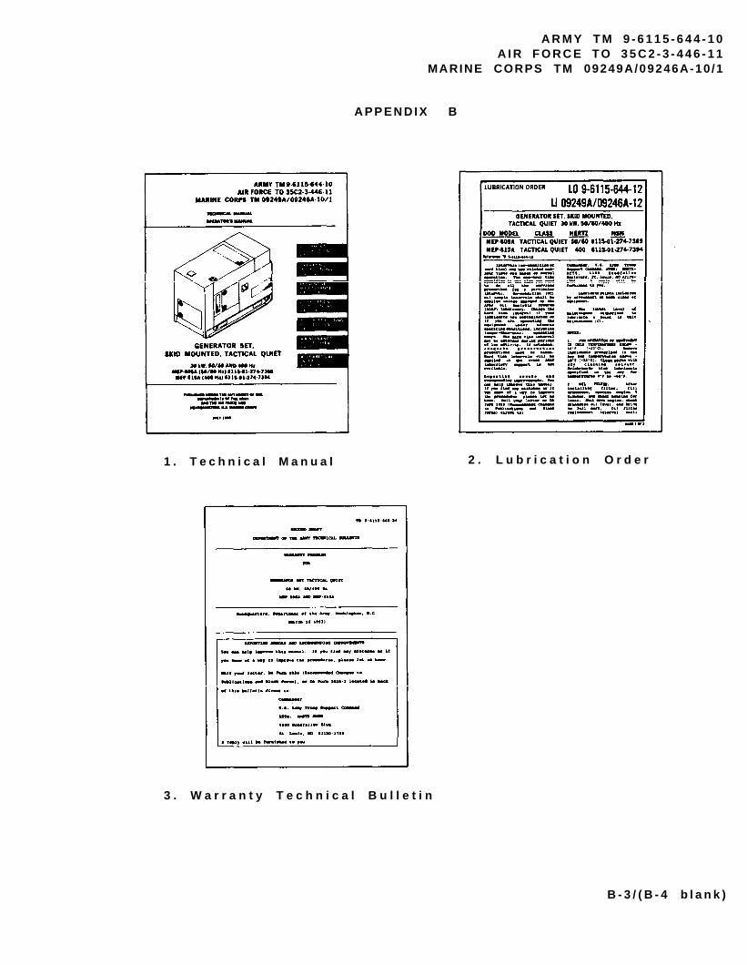
A R M Y T M 9 - 6 1 1 5 - 6 4 4 - 1 0A I R F O R C E T O 3 5 C 2 - 3 - 4 4 6 - 1 1
MARINE CORPS TM 09249A/09246A-10 /1
A P P E N D I X B
1 . T e c h n i c a l M a n u a l
3 . W a r r a n t y T e c h n i c a l B u l l e t i n
2 . L u b r i c a t i o n O r d e r
B - 3 / ( B - 4 b l a n k )


A R M Y T M 9 - 6 1 1 5 - 6 4 4 - 1 0A I R F O R C E T O 3 5 C 2 - 3 - 4 4 6 - 1 1
MARINE CORPS TM 09249A/09246A-10 /1
APPENDIX C
ADDITIONAL AUTHORIZATION L IST
SECTION I. NTRODUCTION.
C - 1 S C O P E .
T h i s a p p e n d i x l i s t sa d d i t i o n a l i t e m s y o u a r ea u t h o r i z e d f o r t h e s u p p o r t o ft h e g e n e r a t o r s e t .
C - 2 G E N E R A L .
T h i s l i s t i d e n t i f i e s i t e m st h a t d o n o t h a v e t o a c c o m p a n yt h e g e n e r a t o r s e t a n d t h a t d on o t h a v e t o b e t u r n e d i n w i t hi t . T h e s e i t e m s a r e a l la u t h o r i z e d t o y o u b y C T A , M T O E ,T D A , o r J T A .
C - 3 E X P L A N A T I O N O F L I S T I N G .
N a t i o n a l s t o c k n u m b e r s ,d e s c r i p t i o n s , a n d q u a n t i t i e s a r ep r o v i d e d t o h e l p y o u i d e n t i f ya n d r e q u e s t t h e a d d i t i o n a l i t e m sy o u r e q u i r e t o s u p p o r t t h i se q u i p m e n t . T h e i t e m s a r e l i s t e di n a l p h a b e t i c a l s e q u e n c e b y i t e mn a m e u n d e r t h e t y p e d o c u m e n t( i . e . , C T A , M T O E , T D A , o r J T A )
w h i c h a u t h o r i z e s t h e i t e m ( s ) t oy o u .
S E C T I O N I I . A D D I T I O N A L A U T H O R I Z A T I O N L I S T
( 1 ) ( 2 ) ( 3 ) ( 4 )
NATIONAL DESCRIPTIONSTOCK QTY
NUMBER CAGE & PART NUMBER USABLE ON CODE U / M AUTH
TBD FIRE EXTINGUISHER EA 1
TED FUEL ADAPTER EA 1
TBD FUEL CAN EA 1
TBD FLEXIBLE SPOUT EA 1
TBD HAMMER, SLIDE EA 1
C - 1 / ( C - 2 b l a n k )


A R M Y T M 9 - 6 1 1 5 - 6 4 4 - 1 0A I R F O R C E T O 3 5 C 2 - 3 - 4 4 6 - 1 1
MARINE CORPS TM 09249A/09246A-10 / l
APPENDIX D
EXPENDABLE/DURABLE SUPPLIES AND MATERIALS LIST
SECTION I INTRODUCTION
D - 1 S C O P E .
T h i s a p p e n d i x l i s t se x p e n d a b l e / d u r a b l e s u p p l i e s a n dm a t e r i a l s y o u w i l l n e e d t oo p e r a t e a n d m a i n t a i n t h egenerator set. This listing isf o r i n f o r m a t i o n a l p u r p o s e s o n l ya n d i s n o t a u t h o r i t y t or e q u i s i t i o n t h e l i s t e d i t e m s .T h e s e i t e m s a r e a u t h o r i z e d t oY O U b y C T A 5 0 - 9 7 0 ,E x p e n d a b l e / D u r a b l e I t e m s ( e x c e p tM e d i c a l , C l a s s V , R e p a i r P a r t s ,a n d H e r a l d i c I t e m s ) , o rC T A 8 - 1 0 0 , A r m y M e d i c a lD e p a r t m e n t E x p e n d a b l e / D u r a b l eI t e m s .
D - 2 E X P L A N A T I O N O F C O L U M N S .
a . C o l u m n ( 1 ) - I t e mN u m b e r . T h i s n u m b e r i s a s s i g n e dt o t h e e n t r y i n t h e l i s t i n g a n di s r e f e r e n c e d i n t h e n a r r a t i v ei n s t r u c t i o n s t o i d e n t i f y t h em a t e r i a l ( e . g . , “ U s e c l e a n i n gc o m p o u n d , i t e m 5 . A p p x . D " ) .
c . C o l u m n ( 3 ) - N a t i o n a lS t o c k N u m b e r . T h i s i s t h eN a t i o n a l S t o c k N u m b e r a s s i g n e dt o t h e i t e m ; u s e i t t o r e q u e s to r r e q u i s i t i o n t h e i t e m .
d . C o l u m n ( 4 ) -D e s c r i p t i o n . I n d i c a t e s t h eF e d e r a l i t e m n a m e a n d , i fr e q u i r e d , a d e s c r i p t i o n t oi d e n t i f y t h e i t e m . T h e l a s tl i n e f o r e a c h i t e m i n d i c a t e s t h eC o m m e r c i a l a n d G o v e r n m e n t E n t i t y( C A G E ) c o d e i n p a r e n t h e s e s ( )f o l l o w e d b y t h e p a r t n u m b e r .
e . C o l u m n ( 5 ) - U n i t o fM e a s u r e ( U / M ) . I n d i c a t e s t h em e a s u r e u s e d i n p e r f o r m i n g t h ea c t u a l m a i n t e n a n c e f u n c t i o n .T h i s m e a s u r e i s e x p r e s s e d b y at w o - c h a r a c t e r a l p h a b e t i c a la b b r e v i a t i o n ( e . g . , e a , i n , p r ) .I f t h e u n i t o f m e a s u r e d i f f e r sf r o m t h e u n i t o f i s s u e ,r e q u i s i t i o n t h e l o w e s t u n i t o fi s s u e t h a t w i l l s a t i s f y y o u rr e q u i r e m e n t s .
b . C o l u m n ( 2 ) - L e v e l .T h i s c o l u m n i d e n t i f i e s t h el o w e s t l e v e l o f m a i n t e n a n c e t h a tr e q u i r e s t h e l i s t e d i t e m .
D - 1

A R M Y T M 9 - 6 1 1 5 - 6 4 4 - 1 0A I R F O R C E T O 3 5 C 2 - 3 - 4 4 6 - 1 1MARINE CORPS TM 09249A/09246A-10 /1
( 1 )
I T E MNUMBER
1
2
3
4
5
( 2 )
LEVEL
C
C
C
C
C
APPENDIX D
( 3 )NATIONAL
STOCKNUMBER
7 9 2 0 - 0 1 - 3 3 8 - 3 3 2 9
6 8 5 0 - 0 0 - 1 8 1 - 7 9 2 9
6 8 1 0 - 0 0 - 1 0 7 - 1 5 1 0
9 1 5 0 - 0 0 - 1 8 9 - 6 7 2 7
9 1 5 0 - 0 1 - 1 5 2 - 4 1 1 7
( 4 )
DESCRIPTION
CLOTH, CLEANING
ANTIFREEZE( 8 1 3 4 9 ) M I L - A - 4 6 1 5 3
WATER, DISTILLED
LUBRICATING OIL , ENG( 8 1 3 4 9 ) M I L - L - 2 1 0 4 ,
OEA HDO 10
LUBRICATING OIL , ENG( 8 1 3 4 9 ) M I L - L - 2 1 0 4 ,
OEA HDO 15/40
(5 )
U / M
EA
GL
GL
QT
QT
D - 2

A R M Y T M 9 - 6 1 1 5 - 6 4 4 - 1 0A I R F O R C E T O 3 5 C 2 - 3 - 4 4 6 - 1 1
MARINE CORPS TM 09249A/09246A-10 /1
INDEX
S u b j e c t
A
Abbreviations, List of . . . . . . . . . . . . . . . . .AC Generator, Location of . . . . . . . . . . . . . . . .Additional Authorization List . . . . . . . . . . . . . .After You Operate PMCS. . . . . . . . . . . . . . . . .A i r C l e a n e r A s s e m b l y , I n s p e c t i o n a n d S e r v i c i n g o f . . . .Air Cleaner Assembly, Location of . . . . . . . . . . . .Air Cleaner Element, Replacement of . . . . . . . . . . . . . . . . .. . .A i r I n t a k e a n d E x h a u s t S y s t e m , D e s c r i p t i o n o f . . . . . .A l t e r n a t o r , L o c a t i o n o f . . . . . . . . . . . . . . . . Assembly and Preparation for Use . . . . . . . . . . . .
B
Batteries, Inspection and Servicing of . . . . . . . . .Batteries, Location of . . . . . . . . . . . . . . . . .Battle Short Switch, Use of . . . . . . . . . . . . . . .Before You Operate PMCS . . . . . . . . . . . . . . . . .
C
C o m p o n e n t s o f E n d I t e m a n d B a s i c I s s u e I t e m s . . . . . .Control Panel, Description of . . . . . . . . . . . . . .Control Panel Assembly, Location of . . . . . . . . . . .Controls and Indicators . . . . . . . . . . . . . . . . .Convenience Receptacle, Location of . . . . . . . . . .Coolant Specifications . . . . . . . . . . . . . . . . .Cooling System, Inspection and Servicing of . . . . . . .
D
Daily Checks . . . . . . . . . . . . . . . . . . . . . .Dead Crank Switch, Location of . . . . . . . . . . . . .Dipstick, Location of . . . . . . . . . . . . . . . . . .D e s c r i p t i o n a n d U s e o f O p e r a t o r ’ s C o n t r o l s a n d I n d i c a t o r sDiesel Fuel Specifications . . . . . . . . . . . . . . .Differences Between Models . . . . . . . . . . . . . . .
E
Emergency Stopping . . . . . . . . . . . . . . . . . . .Engine, Location of. . . . . . . . . . . . . . . . . . .
P a g e
1 - 31 - 6C - 12 - 83 - 1 21 - 63 - 1 31 - 1 51 - 42 - 1 7
3 - 1 11 - 42 - 4 02 - 8
B - 12 - 11 - 62 - 31 - 73 - 1 43 - 1 3
2 - 2 11 - 71 - 62 - 13 - 1 51 - 7
2 - 4 01 - 4
I - 1

A R M Y T M 9 - 6 1 1 5 - 6 4 4 - 1 0A I R F O R C E T O 3 5 C 2 - 3 - 4 4 6 - 1 1MARINE CORPS TM 09249A/09246A-10 /1
INDEX (CONTINUED)
S u b j e c t P a g e
E (CONTINUED)
Engine, Servicing Lube Oil . . . . . . . . . . . . . . . . . . . . .Eng ine Coo l ing Sys tem, Descr ip t ion o f . . . . . . . . . . . . . . . . .E n g i n e L u b r i c a t i o n S y s t e m , D e s c r i p t i o n o f . . . . . . . . . . . . . .E n g i n e S t a r t i n g S y s t e m , D e s c r i p t i o n o f . . . . . . . . . . . . . .Equipment Character ist ics, Capabi l i t ies and Features . . . . . . . . . . . .Equipment Data . . . . . . . . . . . . . . . . . . . . . .Equipment Description . . . . . . . . . . . . . . . . . . . .E q u i p m e n t i s N o t R e a d y / A v a i l a b l e I f . . . . . . . . . . . . . . . . .Expendable/Durable Supplies and Materials List . . . . . . . . . . . . . . . . . . . . . . . .
F
Fuel Filter/Water Separator, Location of . . . . . . . . . . . . . . . . . . . . . . .Fuel Fi l ter/Water Separator, Servicing of . . . . . . . . . . . . . . . . . .Fuel Specifications . . . . . . . . . . . . . . . . . . . . . . . .. .Fuel System, Description of . . . . . . . . . . . . . . . . . .. .Fuel Tank, Location of . . . . . . . . . . . . . . . . . . . .. . .Fuel Tank, Servicing . . . . . . . . . . . . . . . . . . . . . . .. .
G
General Information . . . . . . . . . . . . . . . . . .. . .Generator Set Inspection and Service . . . . . . . . . . . . . . . . . . . .. .Grounding Rod, Installation of . . . . . . . . . . . . . . . . . . . . . . . . .
H, I, J
How to Use This Manual . . . . . . . . . . . . . . . . . . . . .. .I f Y o u r E q u i p m e n t F a i l s t o O p e r a t e . . . . . . . . . . . . . . .Initial Adjustments . . . . . . . . . . . . . . . . . . .I n s t a l l a t i o n o f G r o u n d i n g R o d . . . . . . . . . . . . . . . . .I n s t a l l a t i o n o f L o a d C a b l e s . . . . . . . . . . . . . . . . . . .
K, L
Lead ing Par t icu lars . . . . . . . . . . . . . . . . . . . . . . . . . . Leakage Definitions for Operators PMCS . . . . . . . . . . . . . . . . . . . . . .List of Abbreviations . . . . . . . . . . . . . . . . . . . . . . . . . . . . . . .Load Cables, Installation of . . . . . . . . . . . . . . . . . . . . . . . . . . . . . .Load Output Termina l Board . . . . . . . . . . . . . . . . . . . . . . .Location and Description of Major Components . . . . . . . . . . . . . . . . . . . . . .L u b r i c a t i o n I n s t r u c t i o n s . . . . . . . . . . . . . . . . . . . . . .
3 - 1 71 - 1 41 - 1 51 - 1 21 - 41 - 71 - 42 - 9D - 1
1 - 71 - 63 - 1 63 - 1 51 - 1 31 - 63 - 1 5
1 - 13 - 1 12 - 1 7
v2 - 82 - 2 12 - 1 72 - 1 7
1 - 72 - 81 - 32 - 1 71 - 61 - 43 - 1
I - 2

A R M Y T M 9 - 6 1 1 5 - 6 4 4 - 1 0A I R F O R C E T O 3 5 C 2 - 3 - 4 4 6 - 1 1
MARINE CORPS TM 09249A/09246A-10 /1
S u b j e c t
INDEX (CONTINUED)
Page
M , N
Lubrication System, Description of . . . . . . . . . . . 1 - 1 5Lubrication System, Inspection and Servicing of. . . . . . . . . . . . . . . 3 - 1 6Maintenance Forms and Records . . . . . . . . . . . . . . 1 - 1Maintenance Procedures . . . . . . . . . . . . . . . . . 3 - 1 1Malfunction Indicator Panel, Location of . . . . . . . . 1 - 6Malfunction Indicator Panel, Description of . . . . . . . 2 - 6Model Numbers and Equipment Names . . . . . . . . . . . . 1 - 1Muffler, Location of . . . . . . . . . . . . . . . . . . 1 - 4
O
Oil, Engine, Checking and Adding . . . . . . . . . . . .Oil Filter, Location of . . . . . . . . . . . . . . . . .Operating Instructions . . . . . . . . . . . . . . . . . . . . . . . . . . . . . . . . . Operating Instructions on Plates . . . . . . . . . . . .Operating Procedures . . . . . . . . . . . . . . . . . .Operating at High Altitudes . . . . . . . . . . . . . . .Operating in Dusty or Sandy Areas . . . . . . . . . . . .O p e r a t i n g i n E x t r e m e C o l d W e a t h e r ( - 2 5 ° F [ - 3 1 ° C ] ) . . . .O p e r a t i n g i n E x t r e m e H e a t A b o v e 1 2 0 ° F ( 4 8 . 8 ° C ) . . . . .Operating in Salt Water Areas . . . . . . . . . . . . . .Operating Under Rainy or Humid Conditions . . . . . . . .Operating Under Unusual Conditions . . . . . . . . . . .Operating Under Usual Conditions . . . . . . . . . . . .Operating Using Battle Short Switch . . . . . . . . . . .Operating While Contaminated . . . . . . . . . . . . . .Output Supply System, Description of . . . . . . . . . . . . . . . . . . . . . . . . . . . . . . . . .
P, Q
Parallel Unit Operation (Load Sharing) . . . . . . . . . . . . . . . . . . . . . . . . .. . . . . . . .Paralleling Receptacle, Location of . . . . . . . . . . . . . . . . . . . . . . . .. . . . . . . .PMCS Procedures. . . . . . . . . . . . . . . . . . . . . . .. . . . . . . . . . . .PMCS Table . . . . . . . . . . . . . . . . . . . . . . . .. . . . . . . . . .Preparation for Movement . . . . . . . . . . . . . . . . . . . . . . . . . . . . . . . . . . . . . . Preventive Maintenance Checks and Services (PMCS) . . . . . . . . . . . . . . . . . . . . . . . . . . . . . .Purpose of Equipment . . . . . . . . . . . . . . . . . . . . . . . . . . . . . . . . . . . .
R
Radiator, Location Of. . . . . . . . . . . . . . . . . . . . . . . . .. . . . . . . . . . . . . . . .References . . . . . . . . . . . . . . . . . . . . . . . . . . . . . . . . . . . . . . . . . . . . . . . . . . . . . . . .
3 - 1 61 - 72 - 12 - 2 92 - 2 12 - 3 92 - 3 72 - 3 72 - 3 72 - 3 92 - 3 82 - 3 72 - 1 72 - 4 02 - 4 01 - 1 6
2 - 2 41 - 72 - 82 - 1 02 - 2 92 - 81 - 1
1 - 4A - 1
I - 3

A R M Y T M 9 - 6 1 1 5 - 6 4 4 - 1 0A I R F O R C E T O 3 5 C 2 - 3 - 4 4 6 - 1 1MARINE CORPS TM 09249A/09246A-10 /1
INDEX (CONTINUED)
S u b j e c t P a g e
R (CONTINUED)
Removal from Parallel Operation . . . . . . . . . . . . . . . . . . . .R e p o r t i n g a n d C o r r e c t i n g D e f i c i e n c i e s . . . . . . . . . . . . . . .Reporting Equipment Improvement Recommendations (EIR). . . . . . . . . . .
S
Scope of Technical Manual . . . . . . . . . . . . . . . . . . . . . . . . . . . . . . . . . . . .Self Test. . . . . . . . . . . . . . . . . . . . . . . . . . . . . . . . . . . . . . . . .Servicing. . . . . . . . . . . . . . . . . . . . . . . . . . . . . . . . . . . . . . .Skid Base, Location of . . . . . . . . . . . . . . . . . . . . . . . . . . . . . . .S l a v e R e c e p t a c l e , L o c a t i o n . . . . . . . . . . . . . . . . . . . Slave Start ing Procedures . . . . . . . . . . . . . . . . . . . . . . . . . .S t a r t e r , L o c a t i o n o f . . . . . . . . . . . . . . . . . . . . . .Starting Procedure . . . . . . . . . . . . . . . . . . . . . . . . .. .Stopping Procedure . . . . . . . . . . . . . . . . . . . . . . . . . . . . . . . . . . .Symptom Index,Troubleshooting . . . . . . . . . . . . . . . . . . . . . . . . .
Technical Principles of Operation. . . . . . . . . . . . . . . . . . . . . . .Troubleshooting . . . . . . . . . . . . . . . . . . . . . . . .- . .Type of Manual . . . . . . . . . . . . . . . . . . . . . . . . . . . . . .. . .
U , V , W
V o l t a g e R e c o n n e c t i o n T e r m i n a l B o a r d , L o c a t i o n o f . . . . . . .Warranty Information . . . . . . . . . . . . . . . . . . . . . . . . . . . .Water Pump, Location of . . . . . . . . . . . . . . . . . . . . . . . . . . . .While You Operate PMCS . . . . . . . . . . . . . . . . . . . . . . . .
2 - 2 82 - 91 - 1
1 - 12 - 2 13 - 1 11 - 61 - 62 - 3 91 - 42 - 2 22 - 2 43 - 2
T
1 - 1 23 - 11 - 1
1 - 61 - 31 - 72 - 8
X , Y , Z
I - 4

TM 9-6115-644-10TO 35C2-3-446-11
TM 09249A/09246A-10/1
By Order of the Secretaries of the Army, Air Force, and Navy (including the Marine Corps):
Official:
MILTON H. HAMILTONAdministrative Assistant to the
Secretary of the Army05054
GORDON R. SULLIVANGeneral, United States Army
Chief of Staff
MERRILL A. McPEAKGeneral, USAFChief of Staff
Official:
RONALD W. YATESGeneral, USAFCommander Air Force Materiel Command
DAVID E. BOTTORFFRear Admiral, CEC, US NavyCommanderNavy Facilities EngineeringCommand
RONALD D. ELLIOTTExecutive DirectorMarine Corps Systems Command
DISTRIBUTION:To be distributed in accordance with DA Form 12–25-E, block no. 5267, requirements for
TM 9-6115-644-10.
*U.S. GOVERNMENT PRINTING OFFICE 1993-755-120, 60276


PIN: 071029-000