Embed Size (px)
Citation preview

OPERATOR'S MANUAL FOR RT60 ROUGH TERRAIN CRANE
Address:Quantang Indust=rial Park, 2nd Yuanda Road, Changsha Economic and Technological Development Zone, Hunan Province, ChinaPostcode: 410131Website: www.zoomlion.com

RT60 ROUGH TERRAIN CRANE
OPERATOR’S MANUAL
Edition 1
Dec. 2013


RT60 Rough Terrain Crane I
Zoomlion Cranes appreciates your selection of the ZOOMLION Rough Terrain Crane for your application.
No one should operate the crane unless they read and understand the information in this manual.
When you follow the instructions in this manual, your crane can operate at MAXIMUM EFFICIENCY.
The operator must keep this manual in the cab of the crane.
If there is anything in the manual that you do not understand, speak with us. We (Zoomlion Cranes) are NOT responsible for damages from an operator who does not obey the instructions in the OPERATOR’S MANUAL.
The OPERATOR’S MANUAL is an important part of the crane. If the crane becomes the property of a different person, make sure that the manual stays in the cab of the crane.
THANK YOU!
Mobile Crane Branch Company of ZOOMLION Heavy Industry Science and Technology Co., Ltd.
Copyright
Under the copyright laws, this manual may not be copied, photocopied, reproduced, translated, or reduced to any electronic medium or machine readable form, in whole or part, without the prior written consent of Zoomlion Heavy Industry Science and Technology Co., Ltd.
Copyright © 20XX, Zoomlion Heavy Industry Science and Technology Co., Ltd.
All rights reserved.
II RT60 Rough Terrain Crane
Hazard Indicators
DANGER, WARNING, CAUTION, ATTENTION, NOTE, and IMPORTANT labels are on signs and decals, and as you read this manual to show important instructions. In this manual, DANGER, WARNING, and CAUTION labels are before the paragraph or item to which they apply. ATTENTION, NOTE, and IMPORTANT follow the paragraph or item they apply to. The markers are as follows:
Refers to a dangerous situation which, if you do not prevent, will cause death or injury.
Refers to a possible dangerous situation which, if you do not prevent, could cause death or injury.
Refers to a possible dangerous situation which, if you do not prevent, may cause light or moderate injury.
Attention
Refers to a situation which, if you do not prevent, may cause property or equipment damage.
Note
Refers to a tip or hint in the operation instructions.
Emphasizes the importance of the data in this manual.
This symbol shows a step or procedure that is not approved and can cause a dangerous situation.
Caution
Warning
Danger
Important
RT60 Rough Terrain Crane III
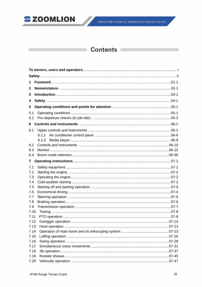
To owners, users and operators ............................................................................................... I
Safety . ........................................................................................................................................ II
1 Foreword ......................................................................................................................... 01-1
2 Nomenclature ................................................................................................................. 02-1
3 Introduction .................................................................................................................... 03-1
4 Safety . ............................................................................................................................. 04-1
5 Operating conditions and points for attention . .......................................................... 05-1
5.1 Operating conditions ..................................................................................................... 05-1 5.2 Pre-departure checks (to job-site) . ............................................................................... 05-3
6 Controls and instruments . ............................................................................................ 06-1
6.1 Upper controls and instruments . .................................................................................. 06-1 6.1.1 Air conditioner control panel . ............................................................................ 06-6 6.1.2 Media player ...................................................................................................... 06-9
6.2 Controls and instruments . .......................................................................................... 06-10 6.3 Monitor ........................................................................................................................ 06-15 6.4 Boom mode selection .................................................................................................. 06-36
7 Operating instructions ................................................................................................... 07-1
7.1 Safety equipment .......................................................................................................... 07-1 7.2 Starting the engine ........................................................................................................ 07-2 7.3 Operating the engine ..................................................................................................... 07-2 7.4 Cold weather starting .................................................................................................... 07-2 7.5 Starting off and parking operation . ................................................................................ 07-3 7.6 Economical driving ........................................................................................................ 07-4 7.7 Steering operation ......................................................................................................... 07-5 7.8 Braking operation .......................................................................................................... 07-6 7.9 Transmission operation ................................................................................................. 07-7 7.10 Towing ......................................................................................................................... 07-8 7.11 PTO operation ............................................................................................................. 07-8 7.12 Outrigger operation ................................................................................................... 07-10 7.13 Hoist operation .......................................................................................................... 07-13 7.14 Operation of main boom and its telescoping system . ............................................... 07-23 7.15 Luffing operation ....................................................................................................... 07-26 7.16 Swing operation ........................................................................................................ 07-28 7.17 Simultaneous crane movements . ............................................................................. 07-31 7.18 Jib operation .............................................................................................................. 07-37 7.19 Rooster sheave ......................................................................................................... 07-45 7.20 Vehicular operation ................................................................................................... 07-47
IV RT60 Rough Terrain Crane
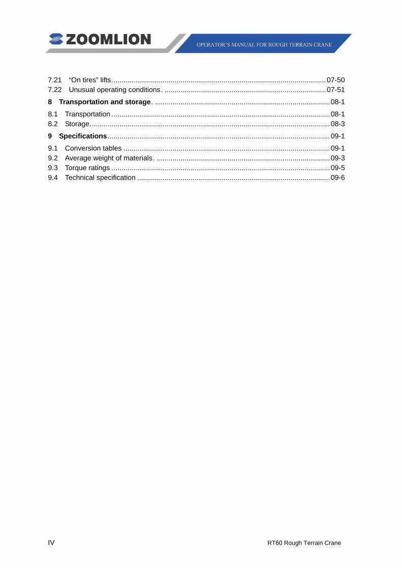
7.21 “On tires” lifts ............................................................................................................. 07-50 7.22 Unusual operating conditions . .................................................................................. 07-51
8 Transportation and storage . ......................................................................................... 08-1
8.1 Transportation ............................................................................................................... 08-1 8.2 Storage.......................................................................................................................... 08-3
9 Specifications ................................................................................................................. 09-1
9.1 Conversion tables ......................................................................................................... 09-1 9.2 Average weight of materials . ........................................................................................ 09-3 9.3 Torque ratings ............................................................................................................... 09-5 9.4 Technical specification .................................................................................................. 09-6


RT60 Rough Terrain Crane 01 - 1
The owner of this crane must know federal, state and local rules. When your equipment is in operation, the area must be safe for employees and non-employees. Do not cause damage to other equipment or local structures while you operate this crane. The rules change by location and this manual does not give that data.
ZOOMLION makes manuals for different construction and industrial equipment. It is policy to include applicable national consensus, industry standards and safety data with the manuals. Use these data to give applicable training to personnel who are to operate, do the maintenance and supervise the equipment correctly and safely.
We make equipment for heavy-duty labor. Do the periodic inspections regularly because the equipment wears. This prevents accidents, decreases downtime and helps equipment work satisfactorily. The goal of these inspections is to find worn, cracked, damaged parts and loose or missing fasteners before they cause a problem.
Correct training and inspection procedures are necessary to prevent injury to persons, property damage and high maintenance costs.
Read and understand the data that comes with this crane. Help is available from the distributors of your ZOOMLION crane and from the ZOOMLION Mobile Crane Branch Company.
This manual contains the instructions and data on the operation, maintenance, lubrication, and adjustments of the Rough Terrain Crane. Do not operate the crane before you understand the data in this manual.


RT60 Rough Terrain Crane 02 - 1
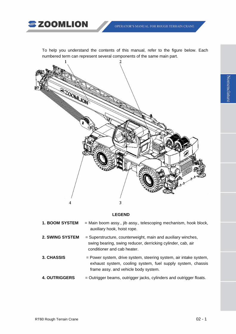
To help you understand the contents of this manual, refer to the figure below. Each numbered term can represent several components of the same main part.
LEGEND
1. BOOM SYSTEM = Main boom assy., jib assy., telescoping mechanism, hook block, auxiliary hook, hoist rope.
2. SWING SYSTEM = Superstructure, counterweight, main and auxiliary winches, swing bearing, swing reducer, derricking cylinder, cab, air conditioner and cab heater.
3. CHASSIS = Power system, drive system, steering system, air intake system, exhaust system, cooling system, fuel supply system, chassis frame assy. and vehicle body system.
4. OUTRIGGERS = Outrigger beams, outrigger jacks, cylinders and outrigger floats.


RT60 Rough Terrain Crane 03 - 1
CRANE PERIODIC INSPECTION CHECKLIST
This inspection checklist provides supplementary data to facilitate the correct operation and maintenance of the crane.
Com
pone
nt
Insp
ecte
d
Inte
rval
Func
tion
Adj
ustin
g C
ondi
tion
Mai
nten
ance
co
nditi
on
Com
pone
nt
Insp
ecte
d
Insp
ectio
n C
ode
Func
tion
Adj
ustin
g C
ondi
tion
Mai
nten
ance
C
ondi
tion

03 - 2 RT60 Rough Terrain Crane
MAINTENANCE LOG
Item Adjusting Condition Date
RT60 Rough Terrain Crane 03 - 3
About This Manual
General
The data (data, specifications, illustrations) in this manual is for cranes in production at the time of this manuals publication. We reserve the right to make changes to this manual at any time, without obligation.
This manual contains the instructions to move and operate the RT75 Crane in the field. Follow the operation and maintenance procedures to make sure that your machine operates at MAXIMUM EFFICIENCY. Use the CRANE PERIODIC INSPECTION CHECKLIST. Keep a maintenance log to monitor all maintenance work on the machine.
An example of a Maintenance Log and Crane Periodic Inspection Checklist is at the beginning of this section.
Again, we appreciate your selection of our crane. User safety is most important. To complete on-site tasks safely, operators must be responsible. Obey the instructions that follow:
Comply – with Occupational Safety and Health Administration (OSHA), Federal, State, and Local Regulations.
Read, Understand, and Follow – the instructions in this and other manuals and documents that come with the crane.
Use Good, Safe Work Practices – in a common sense way.
Only have trained operators – directed by informed and knowledgeable job-site supervisors.
Do not use this crane – before the portable fire extinguisher, installed in the cab, agrees with local fire protection rules.
Note
OSHA prohibits the alteration or modification of this crane without written manufacturer’s approval. Use only factory approved parts to service or repair the crane.
If you make modifications/additions "which affect the safe operation of the equipment" to the crane before you use it, the crane owner must make sure that the modifications/additions agree with OSHA 1926:1412.

03 - 4 RT60 Rough Terrain Crane
Speak with us if special data is necessary for the maintenance or operation of your RT75 Crane. Send your machine model and a serial number to make sure that you receive the correct data.
If there is anything in this manual that is not clear or which you think is necessary, write to the address that follows:
Rough Terrain Crane R & D Institute
Zoomlion Mobile Crane Branch Company
Quantang Industrial Park, 2nd
Economic and Technological Development Zone,
Yuanda Road,
Changsha, Hunan Province, China, 410131
You can also speak to us by telephone at 0086-84671987 (international), 0731-84671987 (domestic).


RT60 Rough Terrain Crane 04 - 1
4.1 HAZARD INDICATORS
DANGER, WARNING, CAUTION, ATTENTION, NOTE, and IMPORTANT labels are on signs and decals, and as you read this manual to show important instructions. In this manual, DANGER, WARNING, and CAUTION labels are before the paragraph or item to which they apply. ATTENTION, NOTE, and IMPORTANT follow the paragraph or item they apply to. The markers are as follows:
Refers to a dangerous situation which, if you do not prevent, will cause death or injury.
Refers to a possible dangerous situation which, if you do not prevent, could cause death or injury.
Refers to a possible dangerous situation which, if you do not prevent, may cause light or moderate injury.
Attention
Refers to a situation which, if you do not prevent, may cause property or equipment damage.
Note
Refers to a tip or hint in the operation instructions.
Important
Emphasizes the importance of the data in this manual.
This symbol shows a step or procedure that is not approved and can cause a dangerous situation.
Caution
Warning
Danger
04 - 2 RT60 Rough Terrain Crane
4.2 SAFETY SYMBOL
The safety symbol, used on the Danger, Warning, and Caution labels, tells personnel of possible death, injury, or property damage. Obey all safety data that follows this symbol to prevent dangerous conditions.
4.3 Hazard classification
Hazard classification is a system to show different classes of possible injury levels. A safety symbol and a signal word show how dangerous the level of possible injury can be.
A signal word without a safety symbol refers to property damage, protection devices, or important data. You will find this system used in this manual and on signs on the crane to help find and prevent dangerous situations.
4.4 SAFETY
This section contains the safety rules that you must follow. You must read and understand the Operator’s Manual. It contains the instructions for the specified machine.
All personnel must be safe at the work location.
Attention
A. Moving personnel
Only use a crane to lift personnel when it is the less dangerous mode to move them to areas that are hard to access.
B. Operator’s responsibilities
Read and understand the Operator's Manual.
The operator must always think about the safety of all personnel in the area.
Only personnel who show that they can safely control a RT75 crane can operate the crane.
Comply with the requirements, that apply, as follows:
Occupational Safety and Health Administration (OSHA) standards
American National Standards Institute (ANSI)
China National Standards GB/T3811.
Make sure that all the mechanical functions of the crane can operate.
Caution
Warning
Danger
RT60 Rough Terrain Crane 04 - 3
Make sure that the system operating gauges and indicators, and warning signals function.
Keep all the glazed surfaces, instruments, windows, and lights clean.
Remove all oil, grease, mud, ice, and snow from walkway surfaces.
Read and understand all Decals and Warnings.
Keep all tools and other necessary items in the toolbox.
Do not lift a load without a Load Ratings in the cab.
Read and understand the Load Ratings.
Make sure that the load to lift is less than the capacity of the crane.
Be in good physical condition and free from effects of alcohol, drugs and medications. Be sure to not decrease vision, hearing, or reaction time.
Keep personnel, equipment and material that are not necessary for your task at the job-site out of the area.
The operator must know the hand signals.
When the view of the operator is blocked or if the task is in a dangerous area, use signal personnel to give directions.
If a signal person is necessary, the operator must obey only the signals from the approved signal person. You must obey the STOP signal from all personnel in the area.
Keep a fully charged fire extinguisher and first aid kit in the cab at all times. The operator must know how to use the fire extinguisher and how to apply the items in the first aid kit.
Look for the movement of other equipment, trucks, and personnel at the job-site.
Personnel must stay off the crane platform while the crane is in operation.
All personnel must be in a safe area before you move the hook, boom, load, or outriggers.
Stop and start the movement of the load smoothly and move at a speed that keeps the load in your control.
Keep a minimum of three full wraps of wire rope on the drum.
Use the tag lines to keep the load in control.
Keep the load near the ground.
Use the shortest boom possible.
If a load is off the ground or the crane is on, you must stay in the cab.
Always use outriggers as the Load Ratings and Operator’s Manual tells.

04 - 4 RT60 Rough Terrain Crane
C. Signal personnel responsibilities
Use and understand all standard hand signals.
Help the operator to operate safely and satisfactorily. Keep safe all personnel and property.
Understand the work you must do.
Stay where you can see the full operation and where personnel can see you.
D. Responsibilities of all crew members
Correct the conditions and procedures that are not safe.
Obey WARNING signs.
Do your work safely and do not make dangerous conditions.
Know and understand correct procedures for crane erection and rigging.
Tell the operator and the signal person of dangerous conditions (power lines/cables, work surface that is not stable etc.).
E. Management responsibilities
The operator must be competent, in good physical condition and have applicable licenses.
The operator, signal person, and riggers must receive training in correct crane operation.
The operator and the signal person must know all standard hand signals.
Have a supervisor at the job-site to be responsible for safety.
Give crew members the safety instructions and tell them to report conditions that are not safe to the supervisors.
Supply the operator with accurate data on the load that they have to lift.
Make sure that all personnel know applicable OSHA and ANSI B30.5 requirements and the instructions in manuals.
F. Planning the job
Understand the work that you must do.
Think of all possible dangerous conditions/risks at the job-site.
Know the type of personnel that is necessary.
Give the tasks to personnel.
Know the weight of the load that you must lift.
Find the lift-radius, boom angle, and the rated lift limits of the crane.
Tell the signal person how to communicate with the operator.
RT60 Rough Terrain Crane 04 - 5
Use equipment which does the work safely.
Make a decision on how to safely move equipment to the job-site.
Find gas lines, power lines and structures.
Make sure that the work surface can hold the crane and load.
Find out how to rig the load.
If necessary, make the special safety precautions.
Know the weather conditions.
Keep equipment that is not necessary away from the job-site.
Set the crane to use the shortest possible boom and radius.
G. Operator safety check
Safety related items must be in position.
Look at the crane logbook for maintenance and inspection records.
Make sure to complete necessary repairs.
Examine the wire rope for damage (kinks, broken wires etc.).
Make sure that all field modifications are approved.
Do an inspection for air and hydraulic oil leaks.
Examine the control positions before you start the engine.
After you start the engine, examine all the instruments and indicators for the correct values.
Do a test on the controls.
Check brakes.
Lift and hold a load 2 inch (50 mm) off of the work surface to examine the load brakes.
H. Operator aids check
Anti-Two Block devices
Boom angle indicator
Backup alarms
Swing lockout device
Rated capacity indicator (RCI)
3rd
I. Operation overload prevention
wrap indicator.
Know the weight of the load.
Decrease radius at the start of the lift to let the load radius increase during lift.
04 - 6 RT60 Rough Terrain Crane
Know the weight of the hook and rigging.
Know the boom length, jib length, and the area where you have to move the load.
Use next lower rated capacity when working at the boom length or radius between the figures on the rated lifting capacity chart.
Do not lift a load until you know if the load is less than the capacity limit of the crane.
Only operate with the recommended counterweights. It is dangerous if you do not use the approved charts to calculate the decrease or increase in counterweight.
Do not lift the load if winds are dangerous. If necessary, lower the boom.
See the Load Ratings for possible restrictions.
Avoid side loading.
Do not let the load or other objects hit the boom.
Release the load slowly, be sure the boom does not tighten against back stops.
Put the boom point directly above the load.
Be sure that the load hangs freely.
J. Operation setup
Be sure the load-bearing surface can hold the weight of the crane and load.
Make crane level, check frequently, and re-level them when necessary.
Assemble barricades to keep personnel out of the load move radius.
K. Power line safety
Find power lines in the area before you start a task. Follow national and local regulations and ANSI B30.5 when you operate around power lines.
Do not remove the material from below power lines if the boom or crane can touch the lines.
Do not let the crane or load touch electrical lines. Do not go near the minimum permitted clearance for operation of a crane near electrical lines.
If you touch the electrical lines, stay on the crane until the boom moves off the lines or until the power line current is off.
Keep all personnel off the crane if it touches power lines. If you must move from the crane, JUMP, DO NOT STEP OFF. Jump with feet together.
Use a signal person when you operate around power lines
L. Slip and fall prevention
Make sure that you stop the crane before you move on and off the equipment. Do not jump.
Do not use the controls and the steering-wheel as hand holds.
RT60 Rough Terrain Crane 04 - 7
Keep the equipment clean and dry.
Replace all broken ladders.
Keep the non-slip surfaces in good condition.
Wear a safety harness when you climb the counterweight and attach the harness in the necessary points. Do not walk on the boom!
M. Travel
Be careful when you move cranes on or off the job-site.
Look for personnel, power lines, low or narrow clearance, bridge or road load limits, steep hills, or rough terrain.
Correctly stow the boom before you move the crane.
Inflate the tires to the specified pressure.
Move slowly and prevent sudden movement.
Wear seat belt correctly when you move the crane.
Make sure that the travel surface can hold the weight of the crane and load.
Always use the park brake when you park the crane.
N. Safety sign maintenance
During the daily inspection, make sure that the decals show and are in good condition. Replace all missing or damaged safety signs. The safety of the operator is always important.
Use a weak soap and water to clean the safety signs. Do not use solvent-based cleaners. Solvents can cause damage to the safety sign material.
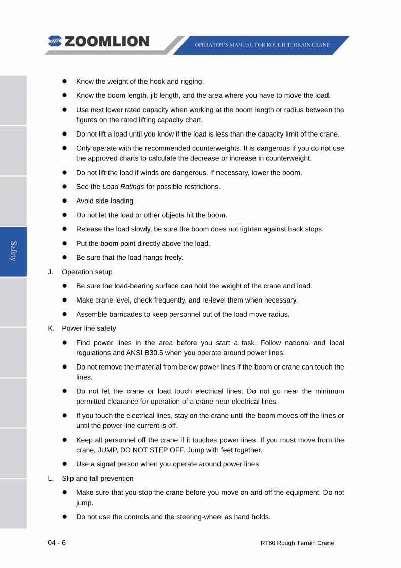
The graphics, on the pages that follow, give an example of each safety decal and its location.
04 - 8 RT60 Rough Terrain Crane
Left-hand side
Right-hand side
Figure 04 – 1 Overview of the Safety Signs on the Machine
RT60 Rough Terrain Crane 04 - 9
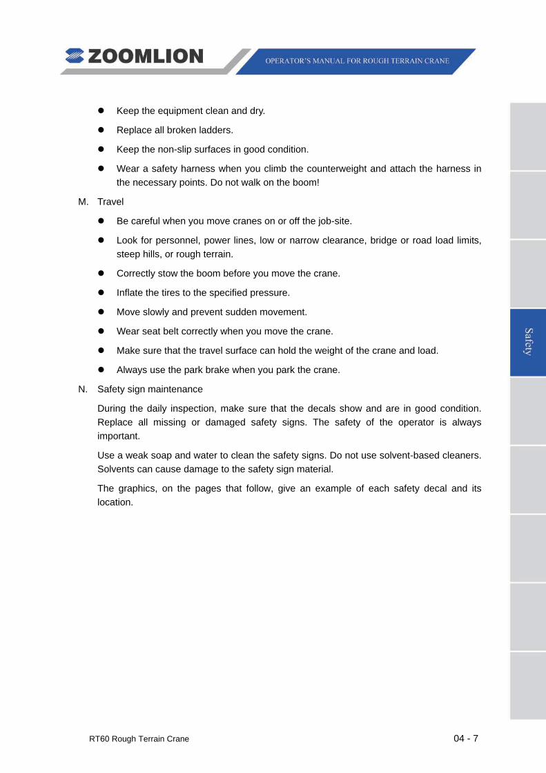
1
Figure 04 – 2 Danger – Crush Hazard
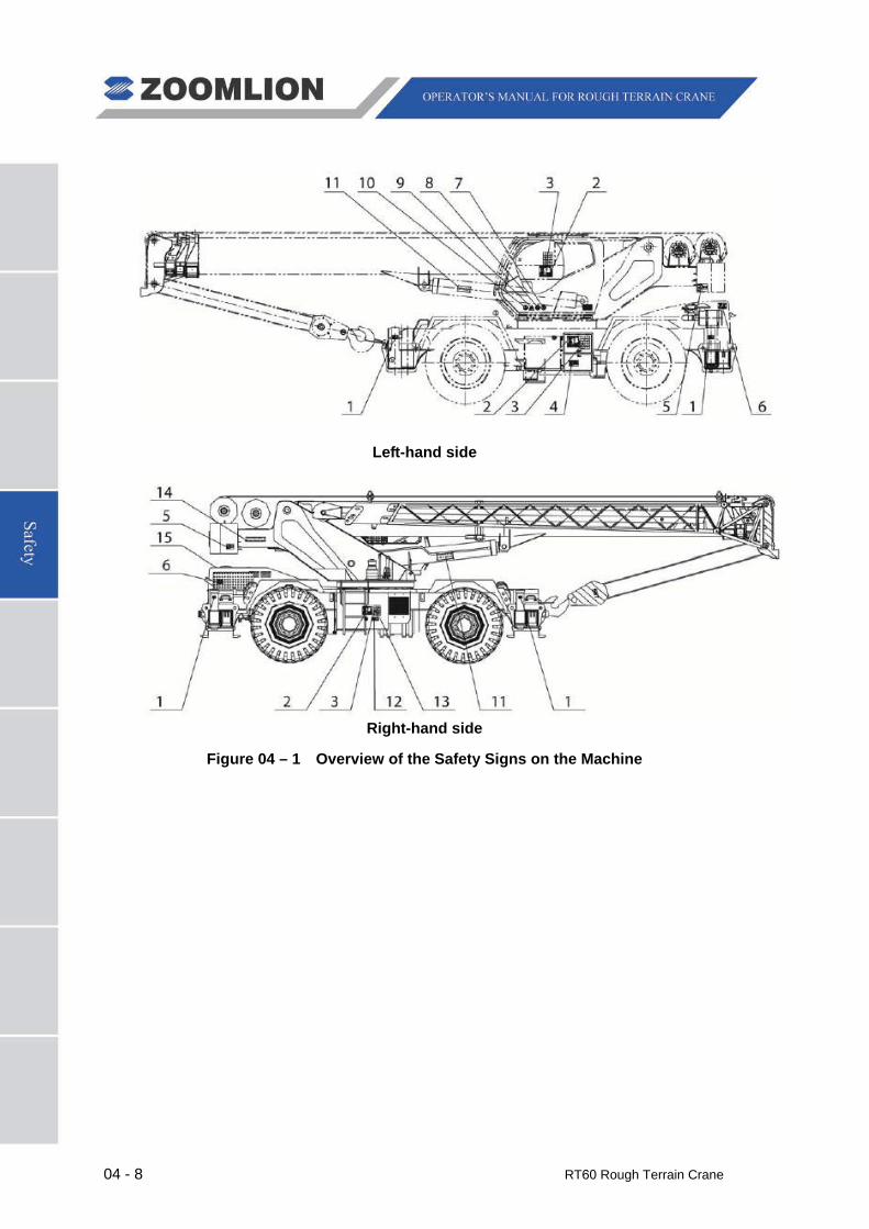
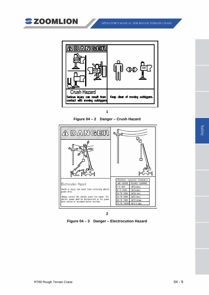
2
Figure 04 – 3 Danger – Electrocution Hazard
04 - 10 RT60 Rough Terrain Crane
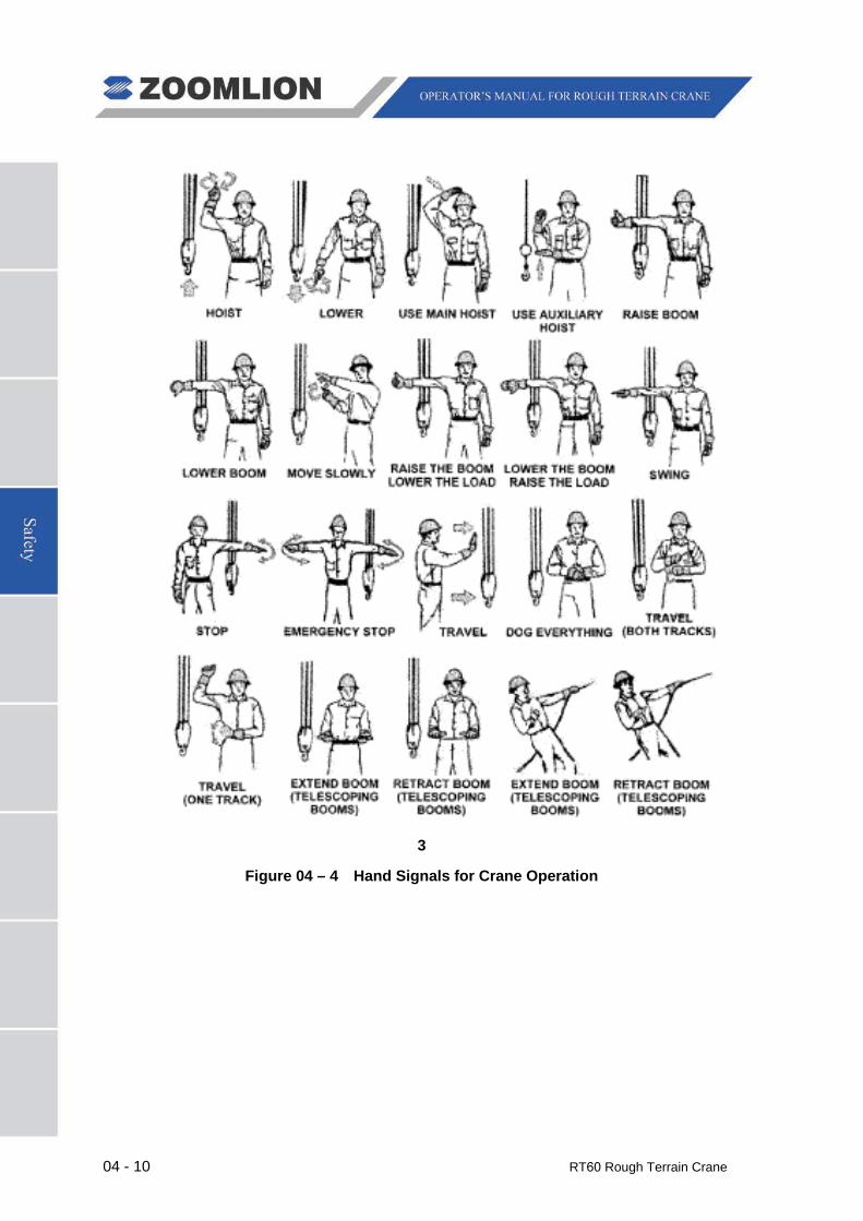
3
Figure 04 – 4 Hand Signals for Crane Operation
RT60 Rough Terrain Crane 04 - 11
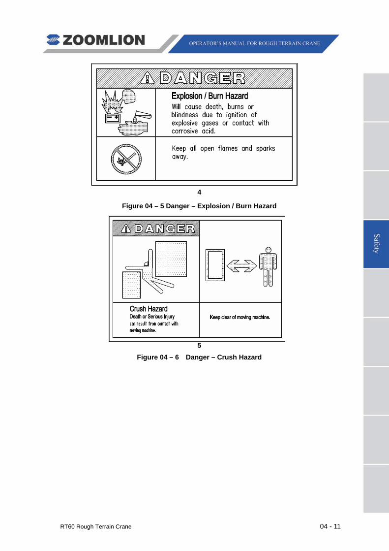
4
Figure 04 – 5 Danger – Explosion / Burn Hazard
5
Figure 04 – 6 Danger – Crush Hazard
04 - 12 RT60 Rough Terrain Crane
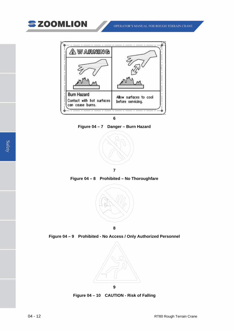
6
Figure 04 – 7 Danger – Burn Hazard
7
Figure 04 – 8 Prohibited – No Thoroughfare
8
Figure 04 – 9 Prohibited - No Access / Only Authorized Personnel
9
Figure 04 – 10 CAUTION - Risk of Falling
RT60 Rough Terrain Crane 04 - 13
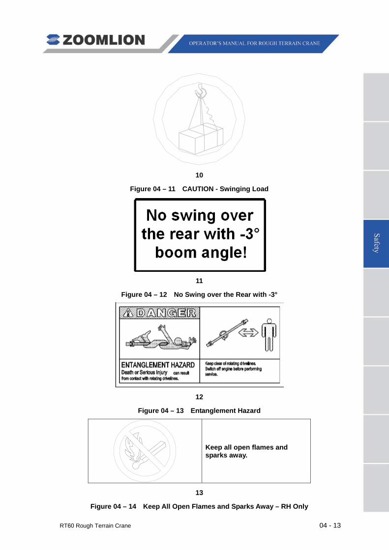
10
Figure 04 – 11 CAUTION - Swinging Load
11
Figure 04 – 12 No Swing over the Rear with -3°
12
Figure 04 – 13 Entanglement Hazard
Keep all open flames and sparks away.
13
Figure 04 – 14 Keep All Open Flames and Sparks Away – RH Only
04 - 14 RT60 Rough Terrain Crane
14
Figure 04 – 15 Be Careful in the Working Radius – RH Only
15
Figure 04 – 16 No Walk – RH Only

RT60 Rough Terrain Crane 05 - 1
5.1 OPERATING CONDITIONS
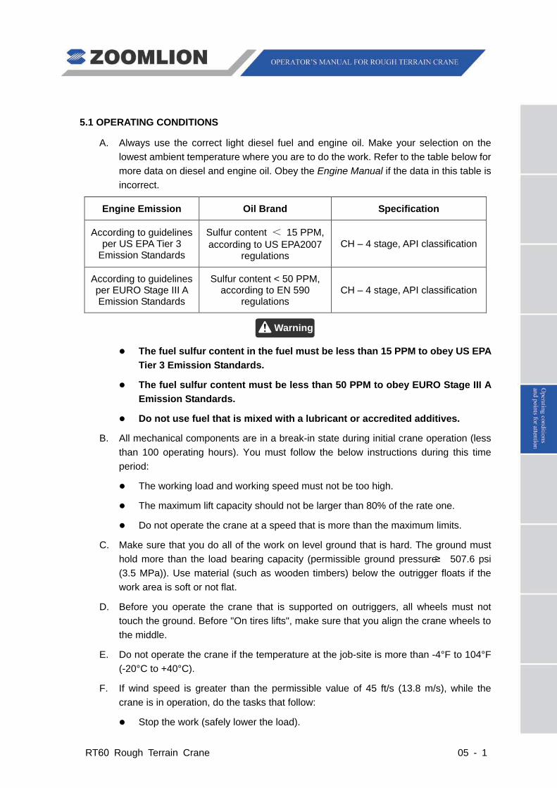
A. Always use the correct light diesel fuel and engine oil. Make your selection on the lowest ambient temperature where you are to do the work. Refer to the table below for more data on diesel and engine oil. Obey the Engine Manual if the data in this table is incorrect.
Engine Emission Oil Brand Specification
According to guidelines per US EPA Tier 3
Emission Standards
Sulfur content < 15 PPM, according to US EPA2007
regulations CH – 4 stage, API classification
According to guidelines per EURO Stage III A Emission Standards
Sulfur content < 50 PPM, according to EN 590
regulations CH – 4 stage, API classification
The fuel sulfur content in the fuel must be less than 15 PPM to obey US EPA Tier 3 Emission Standards.
The fuel sulfur content must be less than 50 PPM to obey EURO Stage III A Emission Standards.
Do not use fuel that is mixed with a lubricant or accredited additives.
B. All mechanical components are in a break-in state during initial crane operation (less than 100 operating hours). You must follow the below instructions during this time period:
The working load and working speed must not be too high.
The maximum lift capacity should not be larger than 80% of the rate one.
Do not operate the crane at a speed that is more than the maximum limits.
C. Make sure that you do all of the work on level ground that is hard. The ground must hold more than the load bearing capacity (permissible ground pressure ≥ 507.6 psi (3.5 MPa)). Use material (such as wooden timbers) below the outrigger floats if the work area is soft or not flat.
D. Before you operate the crane that is supported on outriggers, all wheels must not touch the ground. Before "On tires lifts", make sure that you align the crane wheels to the middle.
E. Do not operate the crane if the temperature at the job-site is more than -4°F to 104°F (-20°C to +40°C).
F. If wind speed is greater than the permissible value of 45 ft/s (13.8 m/s), while the crane is in operation, do the tasks that follow:
Stop the work (safely lower the load).
Warning

05 - 2 RT60 Rough Terrain Crane
Retract the boom.
Correctly stow the boom.
To make an estimate of the wind speed, use the table that follows:
Wind Force Wind Speed Effect of the wind on the land Beaufort
Scale Description ft-in/s m/s
0 Calm 0 - 8″ 0 - 0.2 No wind, smoke rises vertically
1 Light Air 1′-4″ - 4′-7″ 0.4 - 1.4 Wind direction shown by smoke drift but not by wind vanes
2 Light Breeze 5′-3″ - 9′-10″ 1.6 - 3 Wind felt on face, leaves rustle, vanes move by wind
3 Gentle Breeze 11′-2″ - 17′-5″ 3.4 - 5.3
Leaves and small twigs in constant motion, wind extends light flag
4 Moderate Breeze 18′-1″ - 25′-7″ 5.5 - 7.8 Small branches move
5 Fresh Breeze 26′-3″ - 34′-9″ 8 - 10.6 Small trees in leaf begin to sway
6
Strong Wind 35′-5″ - 45′-0″ 10.8 - 13.7
Large branches in motion; difficult to use umbrellas, whistling heard in telegraph wires
7 Near Gale 45′-7″ - 60′-9″ 13.9 - 17 Whole trees in motion, difficult to walk against the wind
8 Gale 56′-5″ - 67′-7″ 17.2 - 20.6 Breaks twigs off trees, impedes progress
9 Strong Gale 68′-3″ - 80′-5″ 20.8 - 24.5
Slight structural damage (roof tiles and chimney covers, etc. blown off)
10 Storm 81′-0″ - 92′-10″ 24.7 - 28.3 Trees uprooted, considerable damage occurs
G. Do not operate the crane until the conditions are safe.
RT60 Rough Terrain Crane 05 - 3
5.2 PRE-DEPARTURE CHECKS (TO JOB-SITE)
A. VEHICLE CHECKS (PRIOR TO ENGINE START)
(1) Do a check of the level of coolant and add more if below the cold engine level.
(2) Do a check of the fuel level and make sure that you have more than is necessary to complete the task.
(3) Make sure that the parts in the steering and brake systems are flexible, safe, and reliable.
(4) Make sure that the parts that follow are tight:
Bolts in universal joints for steering axles
Front and rear axles mounting bolts
Wheel bolts
Drive shaft mounting bolts
Engine and transmission mounting bolts.
(5) Examine all tires for the correct pressure.
(6) Examine the items that follow for damage:
Condition of tires
Door locks
Doors
Windows
Crane control mechanisms.
(7) Examine the fittings of oil pipes, air pipes and water pipes for leakage.
(8) Examine the air pressure tank for condensation (drain the water as necessary).
(9) Examine the battery terminals for too much corrosion and make sure that the power wires are tight.
(10) Examine the level of the battery electrolyte (adjust as necessary).
(11) Examine the air filter indicator. If the indicator is red, clean or replace the filter cartridge.
The air filter system must be clean prior to starting the engine.
(12) Examine the air filter assembly. Clean the contamination from the bottom of the air filter.
(13) Turn the ignition switch to stage “I” and examine the functions of the items that follow:
Caution

05 - 4 RT60 Rough Terrain Crane
Instrument panel
Switches
All lights
Turn signals
Wipers
Miscellaneous displays.
(14) Adjust the mirrors for clear vision to the rear.
B. GENERAL CHECKS AT VEHICLE START UP
Before you start the vehicle on a steep slope or a muddy road, move the transmission gear selector into “F1” position.
Do not turn the power supply OFF while the engine in ON. If you turn the power supply OFF, the electrical system does not operate and you remove the data from the ECU.
((11)) Examine the controls and instruments.
((aa)) Examine the engine oil pressure gauge.
1 The engine oil pressure must be between 240 PSI (1.7 MPa) – 310 PSI (2.1 MPa).
((bb)) Examine the compressed air supply.
((cc)) Examine the engine coolant temperature gauge.
1 After the engine has the time to warm-up, the pointer must point to the green range (between 158° F (70° C) and 203° F (95°C)).
((dd)
) Make sure that the transmission gears shift correctly.
((ee)) Make sure that the 360° superstructure lock moves correctly.
((22)) Make sure that each indicator operates.
((33)) Make sure that the generator operates.
((44)) Make sure that the park brake is not ON.
((55)) Move the transmission gear selector to the “F1” position and slowly increase the speed.
Caution
Caution
RT60 Rough Terrain Crane 05 - 5
C. MOVE THE CRANE TO THE JOB-SITE
Do not let the vehicle move forward when transmission is in neutral.
Do not operate a vehicle if a warning indicator illuminates. Stop the vehicle and have it repaired.
((11)) If a warning indicator illuminates, decrease your speed immediately and stop at a safe location for maintenance checks.
((22)) Do not skip a gear when you move through the gear cycle.
((33)) During driving, if there is any abnormal sound, smell, vibration or acceleration, bring the vehicle to a standstill immediately and check. If the cause of problem is unclear or if the problem cannot be rectified, send the vehicle to the specialized repair factory.
((44)) Stop the vehicle if there are unusual conditions with the items in the below list:
Steering
Braking
Sounds or smells
Vibrations
Sudden speed increase or decrease.
If you cannot find or correct the problem, send the vehicle for repair.
((55)) Check the following instruments for functions:
((66)) Monitor the indicators / gauges that follow:
Stop the engine if the engine oil pressure low indicator illuminates.
The engine oil pressure low indicator illuminates if the engine oil filter screen is dirty. If this occurs, examine the engine oil pressure. If it is in the correct pressure range, check and clean the engine oil filter screen.
((aa)) Engine oil pressure low indicator:
1 Not illuminated.
2 When the engine runs at idle, the minimum oil pressure is 55.1 psi (0.38 MPa). When the engine runs without a load, the minimum oil pressure is 10 psi (0.069 MPa). If the pressure is less than the minimum value, the indicator illuminates. If this occurs, stop the engine. Measure the level of
Caution
Caution
Warning
Danger
05 - 6 RT60 Rough Terrain Crane
the oil in the engine and check for leaks. If the oil level is at the correct level and there are no leaks, it is an unserviceable lubricating system. Send the crane to the factory for repair.
((bb) ) Engine coolant temperature gauge
1 The coolant temperature must be between 158°F and 203° F (70°C and 95°C). Do not move the crane at high speed when the coolant temperature is less than 158°F (70°C).
2 Do not operate the engine at high speeds without a load for extended periods of time.
Do not move the crane at high speeds with a heavy load until the engine coolant temperature is a minimum 158°F (70°C).
3 When the coolant temperature is in the yellow area, between 203°F and 212°F (95°C - 100°C), the engine is too hot. Park the crane. Operate the engine at a RPM immediately above idle to help cool the engine. Or, as you move, put the transmission in a lower gear range to decrease the load on the engine.
Do not stop the engine immediately when the engine coolant temperature is above the maximum limit. If you stop the engine, the coolant temperature increases suddenly and damage to the engine occurs. Operate the engine at a RPM immediately above idle to help decrease the coolant temperature.
4 When the coolant temperature gauge points to the red area, between 212°F and 248°F (100°C - 120°C) continuously, it shows that the engine is above limits. If you stop the engine, the coolant temperature increases suddenly and damage to the engine occurs. Operate the engine at a RPM immediately above idle to help decrease the coolant temperature.
5
When the coolant temperature goes back to the green or yellow area, do the items that follow:
Examine the engine area for leaks.
Examine the function of the thermostat.
Check the coolant level.
Check the fan belt for damage.
Make sure that the fan belt is not too loose.
Do not add a large quantity of cold water to the engine if the engine coolant
Caution
Caution
Caution
RT60 Rough Terrain Crane 05 - 7
temperature is above the maximum limit. This can kill or blind you and cause damage to the engine.
((cc)) Low engine coolant:
Use soft water, e. g. tap water, for coolant. Do not use hard water (river water).
1
Do not add a large quantity of cold water too quickly. When it is necessary to add cold water, put the water in slowly. Follow the below instructions to add coolant:
Put together water, antifreeze and/or anti-rust fluid in the correct ratio.
Loosen the cap to the coolant tank with a wet rag to release the pressure in the tank. After you release the pressure, continue to remove the cap. The fluid released is hot and pressurized and can cause burns or blindness. Always keep your face away from the cap on the coolant tank.
Add the water mix to the applicable coolant tank fill-line and then install the cap.
Do not operate the engine continuously at high speeds without a load.
((77)) Put the crane in a lower gear before you move up a slope to decrease the load on the engine and drive-line.
Note
Make sure that the RPM of the engine is around maximum when you move up a slope.
Do not bypass gears when you move to a lower gear.
Slow the crane down before you change to a lower gear.
((88)) Do the items that follow before you go down a long hill slope:
Make sure that the brake system can stop the crane before you go onto the slope.
Put the transmission in the ”F1” position before you go down the slope.
((99)) Know the below data while you steer the crane:
When you go into a corner, put the transmission in a lower gear and apply a small quantity of pressure on the brakes.
Caution
Caution
Caution
05 - 8 RT60 Rough Terrain Crane
The steering wheel has a mechanical limit. Do not continue to turn the wheel when at the limit. Do not keep the wheel at the limit for long periods of time.
((110
0)) If the engine stops because the fuel tank is empty, air can go into the fuel system. When this occurs, you remove the air from the fuel lines.
((1111)) When you move the crane between locations, only one person is approved to be in the cab.
D. CRANE MOVEMENT IN OFF-ROAD CONDITIONS
When the rear axle is in the mud (no traction) or on rough terrain, follow these steps:
Put the transmission in the ”F1” position. This applies more torque to the drive system.
Put the vehicle in the "4-wheel drive" mode.
Tow the vehicle or put rigid materials, e.g. pieces of wood or iron plates, below the wheels.
E. PARK THE VEHICLE
Make sure that the hazard indicator illuminates when the vehicle is parked on the road at night.
((11)) When you park the vehicle, follow the instructions below:
In bad weather condition (rain, snow, ice) or on a slope, make sure that there is a lot of clearance in front and to the aft of the vehicle.
Put the park brake switch to the "P" position and put the chocks against the wheels.
Put the transmission in the "neutral" position.
((22)) Before you stop the engine, do the items that follow:
Push the accelerator pedal 2 or 3 times to increase the engine RPM. This makes the oil flow into each part of the engine.
Let the engine idle while you monitor the coolant temperature.
Stop the engine, when the coolant temperature is in the correct range.
Put the battery master switch to the OFF position.
F. EMERGENCY STOP ON THE ROADWAY
If the crane malfunctions on the roadway, do the items that follow:
Set the hazard lights to ON and put the safety triangles in position.
Set the park brake if you stop because of a drive train (drive shaft, axle) failure or you make an emergency stop on a slope. Put the chocks on the wheels.
Caution
RT60 Rough Terrain Crane 05 - 9
Examine the vehicle to find the part that caused the malfunction. Be careful of the road conditions while you move around the vehicle.
If you cannot repair the vehicle, tell the servicing and repair facility.
G. PREPARE THE CRANE FOR OPERATION
((11)) Examine the items that follow:
Engine oil for correct level and make sure that it is clean.
Coolant for correct level.
Fuel tank for correct level.
Hydraulic oil tank for correct level.
((22)) Start the engine and check for noises and vibrations that are not usual. If necessary, engage the PTO.
H. WHEN THE CRANE IS IN OPERATION
((11)) Personnel must stay away from the area below the boom.
((22)) Do not let personnel on the superstructure while you operate the crane.
((33)) Personnel must stay away from the reach of the boom.
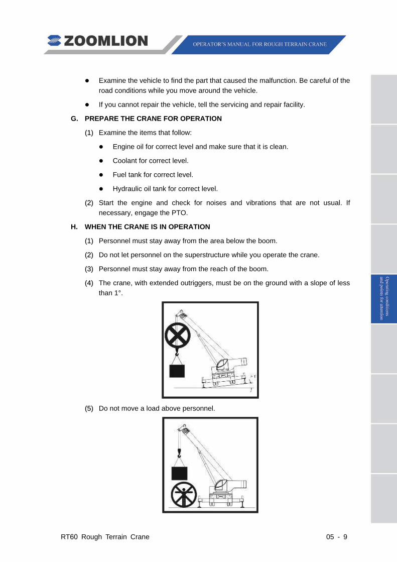
((44)) The crane, with extended outriggers, must be on the ground with a slope of less than 1°.
((5 5)) Do not move a load above personnel.
05 - 10 RT60 Rough Terrain Crane
((6
6)) Do not move personnel on the load or other equipment used to lift.
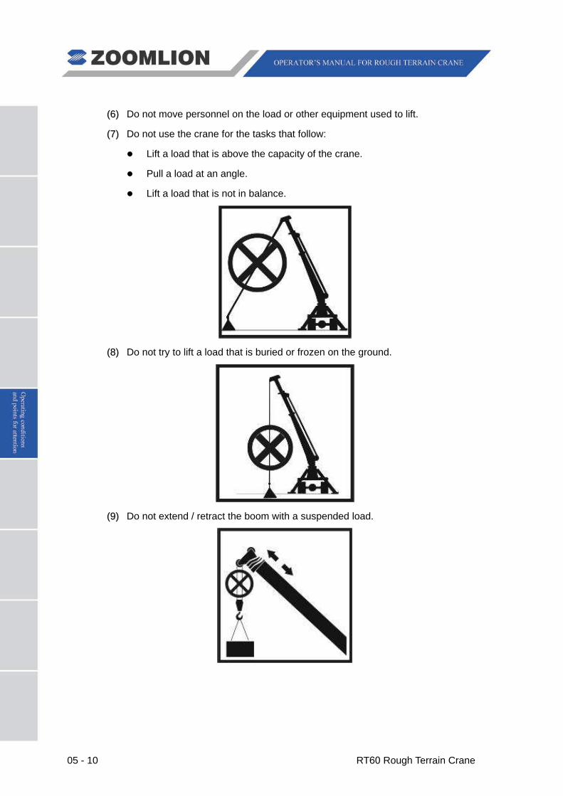
((77)) Do not use the crane for the tasks that follow:
Lift a load that is above the capacity of the crane.
Pull a load at an angle.
Lift a load that is not in balance.
((8 8)) Do not try to lift a load that is buried or frozen on the ground.
((9 9)) Do not extend / retract the boom with a suspended load.

RT60 Rough Terrain Crane 05 - 11
((110 0)) Keep no less than 3 wraps of wire rope on the drum.
((111
1)) When the load is off the ground, do not adjust the hoist mechanism brake.
((1122)) When the load is off the ground, the operator must stay in the cab.
((113 3)) When the job-site is near live power lines, you must keep a safe distance. Make sure that the dangerous area has a cover or is fenced off.
((114
4)) When the load is off the ground, move the load in a slow and smooth direction.
((1155)) Constantly monitor the system gauges and indicators, when the crane is in operation. If you find a malfunction, stop the operation.
((1166)) A noise sounds when the load is at 90% of the capacity of the crane. When this occurs, be careful as you continue to lift.
((1177)) If the crane was changed, do not operate the crane until approved personnel examine the changed part.
05 - 12 RT60 Rough Terrain Crane
((118 8)) Stop the operation or do not start to lift a load, if one of the items that follows occurs:
An overload or if the weight of the load is unknown.
The load lift moves out of position, the rigging becomes too loose or the load is out of balance.
The protective material between the edges of load and wire rope is missing.
The light level at the job-site goes below a safe work condition.
Equipment malfunction or damage to the crane that decreases the safe operation of the crane.
RT60 Rough Terrain Crane 05 - 13
I. TROUBLESHOOTING – ENGINE
If failures occur during crane operation, stop working immediately and remove the safety hazards. At the same time, disengage the PTO for transmission and make the engine run at idle speed. After that, check control instruments, e.g. transmission oil pressure gauge and engine coolant temperature gauge, etc. for functional work.
It is a normal phenomenon that the engine oil pressure low indicator lights up when starting the engine with the PTO engaged. The warning indicator will go off after the oil pressure increases to the specified value.
((11)) The illumination of the engine oil pressure low indicator indicates that the engine oil pressure decreases abnormally. Bring the vehicle to a standstill immediately and contact the manufacturer or specialized repair factory.
Do not turn off the engine immediately when it is overheated. Otherwise, the engine will be sintered caused by sudden raising coolant temperature. Check for leaks when the engine is running for cooling. Stop the engine after the coolant temperature decreases. At this time, reinspect engine coolant level and check fan belt for damages and loosening.
((22)) When the engine coolant temperature gauge points to the red area, cool down the engine at the RPM a little higher than the idle RPM.
Points for attention when adding coolant:
Use proper coolant.
When the coolant temperature is extremely high, hot water will spray. Therefore, tighten or loosen the radiator cover using a piece of cloth. Otherwise, there is a risk of burn hazard.
Caution
Caution
Caution


RT60 Rough Terrain Crane 06 - 1
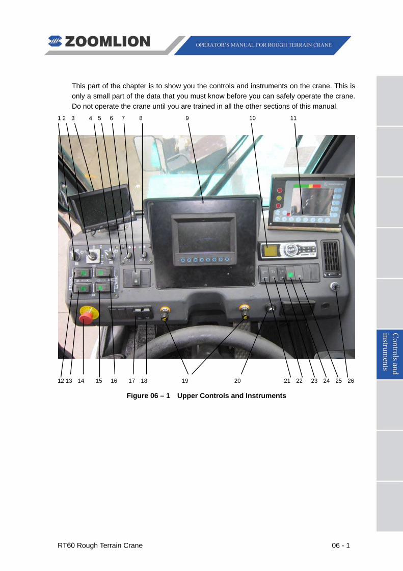
This part of the chapter is to show you the controls and instruments on the crane. This is only a small part of the data that you must know before you can safely operate the crane. Do not operate the crane until you are trained in all the other sections of this manual.
1 2 3 4 5 6 7 8 9 10 11
12 13 14 15 16 17 18 19 20 21 22 23 24 25 26
Figure 06 – 1 Upper Controls and Instruments
06 - 2 RT60 Rough Terrain Crane
LEGEND
1. High / Low Speed Select Switch for Main Winch
2. Steering Switch
3. Camera Display
4. High / Low Speed Select Switch for Aux Winch
5. Air Conditioner Control Panel
6. A/C Fan Speed / Mmaster Switch
7. Cab Heater Power Switch
8. Cab Cooler Power Switch
9. Monitor Display
10. Media Player
11. Rated Capacity Indicator (RCI) Display
12. Left Front Outrigger Switch
13. Left Rear Outrigger Switch
14. Emergency Stop Button
15. Right Front Outrigger Switch
16. Right Rear Outrigger Switch
17. Work Light Switch
18. Hazard Lights Switch
19. Cigarette Lighter
20. Ignition Switch
21. Outrigger Extend / Retract Master Switch
22. Swing Lock Switch
23. 2-Wheel / 4-Wheel Drive Switch
24. Hand / Foot Throttle Select Switch
25. Bypass Switch
26. Hand Throttle

RT60 Rough Terrain Crane 06 - 3
1 2 3 4 5 6 7
8 9 10 11
Figure 06 – 2 Left Dash
1. LEFT REAR OUTRIGGER SWITCH – Used to select outrigger cylinder (jack or beam) to be extended / retracted with OUTRIGGER EXTEND / RETRACT MASTER SWITCH (21) (See Figure 06 – 1).
2. LEFT FRONT OUTRIGGER SWITCH – Used to select outrigger cylinder (jack or beam) to be extended / retracted with OUTRIGGER EXTEND / RETRACT MASTER SWITCH (21) (See Figure 06 – 1).
3. HIGH / LOW SPEED SELECT SWITCH FOR MAIN WINCH – Sets the main winch speed to OFF, LOW or HIGH.
4. RIGHT REAR OUTRIGGER SWITCH – Used to select outrigger cylinder (jack or beam) to be extended / retracted with OUTRIGGER EXTEND / RETRACT MASTER SWITCH (21) (See Figure 06 – 1).
5. RIGHT FRONT OUTRIGGER SWITCH – Used to select outrigger cylinder (jack or beam) to be extended / retracted with OUTRIGGER EXTEND / RETRACT MASTER SWITCH (21) (See Figure 06 – 1).
06 - 4 RT60 Rough Terrain Crane
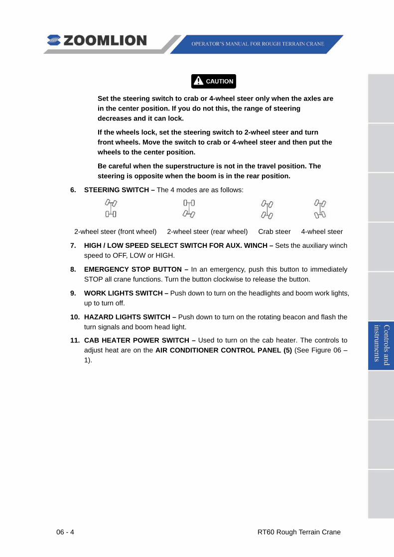
Set the steering switch to crab or 4-wheel steer only when the axles are in the center position. If you do not this, the range of steering decreases and it can lock.
If the wheels lock, set the steering switch to 2-wheel steer and turn front wheels. Move the switch to crab or 4-wheel steer and then put the wheels to the center position.
Be careful when the superstructure is not in the travel position. The steering is opposite when the boom is in the rear position.
6. STEERING SWITCH – The 4 modes are as follows:
2-wheel steer (front wheel) 2-wheel steer (rear wheel) Crab steer 4-wheel steer
7. HIGH / LOW SPEED SELECT SWITCH FOR AUX. WINCH – Sets the auxiliary winch speed to OFF, LOW or HIGH.
8. EMERGENCY STOP BUTTON – In an emergency, push this button to immediately STOP all crane functions. Turn the button clockwise to release the button.
9. WORK LIGHTS SWITCH – Push down to turn on the headlights and boom work lights, up to turn off.
10. HAZARD LIGHTS SWITCH – Push down to turn on the rotating beacon and flash the turn signals and boom head light.
11. CAB HEATER POWER SWITCH – Used to turn on the cab heater. The controls to adjust heat are on the AIR CONDITIONER CONTROL PANEL (5) (See Figure 06 – 1).

06 - 5 RT60 Rough Terrain Crane
1 2 3 4 5
Figure 06 – 3 Right Dash
1. OUTRIGGER EXTEND / RETRACT MASTER SWITCH – Used with switches (12, 13, 15, 16 in Figure 06 – 1) to extend and retract the outrigger beams and jacks. Push down to retract, up to extend.
You must set the swing lock switch to LOCK, when the boom is in the travel position.
2. SWING LOCK SWITCH - Push down to disengage swing lock, up to engage.
Do not use this switch until you stop the crane.
3. 2-WHEEL / 4-WHEEL DRIVE SWITCH – Push up to engage 2-wheel drive, down to engage 4-wheel drive.
4. HAND / FOOT THROTTLE SELECT SWITCH - Push up to select foot throttle, down to select hand throttle.
5. BYPASS SWITCH – Push down to bypass the switch-off when the RCI sounds the alarm and switches off the movements. (BYPASS SWITCH not used with Greer LMI
system.)

RT60 Rough Terrain Crane 06 - 6
6.1.1 AIR CONDITIONER CONTROL PANEL
Figure 06 – 4 Air Conditioner Control Panel
FUNCTIONS
1. A/C FAN SPEED / MASTER SWITCH – Used to control the fan blower modes: OFF, HI, MID, LOW.
2. FAN POWER INDICATOR
3. COOL MODE INDICATOR
4. CAB COOLER POWER SWITCH – Refrigeration ON / OFF. Starts or stops the function of the compressor.
06 - 7 RT60 Rough Terrain Crane
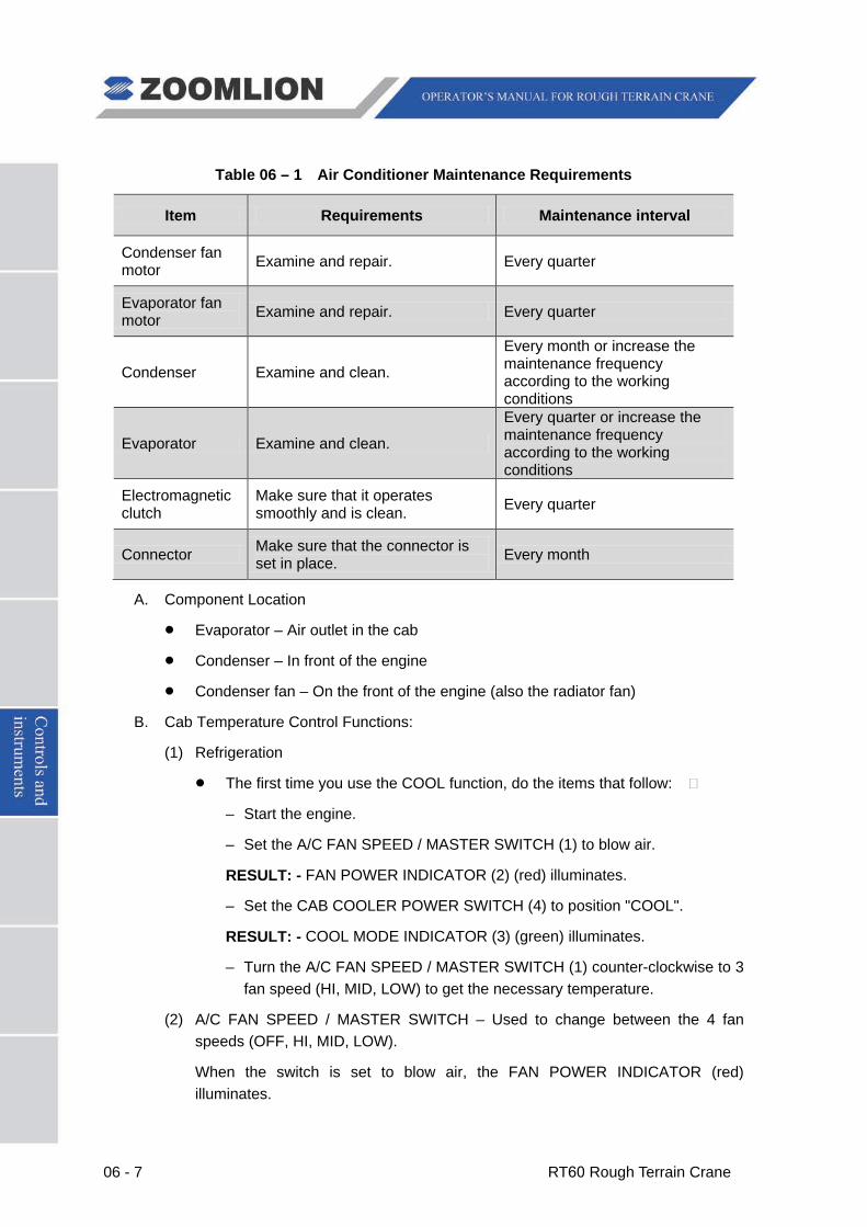
Table 06 – 1 Air Conditioner Maintenance Requirements
Item Requirements Maintenance interval
Condenser fan motor Examine and repair. Every quarter
Evaporator fan motor Examine and repair. Every quarter
Condenser Examine and clean.
Every month or increase the maintenance frequency according to the working conditions
Evaporator Examine and clean.
Every quarter or increase the maintenance frequency according to the working conditions
Electromagnetic clutch
Make sure that it operates smoothly and is clean. Every quarter
Connector Make sure that the connector is set in place. Every month
A. Component Location
Evaporator – Air outlet in the cab
Condenser – In front of the engine
Condenser fan – On the front of the engine (also the radiator fan)
B. Cab Temperature Control Functions:
(1) Refrigeration
The first time you use the COOL function, do the items that follow:
– Start the engine.
– Set the A/C FAN SPEED / MASTER SWITCH (1) to blow air.
RESULT: - FAN POWER INDICATOR (2) (red) illuminates.
– Set the CAB COOLER POWER SWITCH (4) to position "COOL".
RESULT: - COOL MODE INDICATOR (3) (green) illuminates.
– Turn the A/C FAN SPEED / MASTER SWITCH (1) counter-clockwise to 3 fan speed (HI, MID, LOW) to get the necessary temperature.
(2) A/C FAN SPEED / MASTER SWITCH – Used to change between the 4 fan speeds (OFF, HI, MID, LOW).
When the switch is set to blow air, the FAN POWER INDICATOR (red) illuminates.

RT60 Rough Terrain Crane 06 - 8
Note
The switch is the master power to the COOL function and must be ON (HI, MID, LOW) for the COOL function to operate.
(3) HEAT mode
Turn on the A/C FAN SPEED / MASTER SWITCH (1) after the engine is started:
– Set the A/C FAN SPEED / MASTER SWITCH (1) to blow air.
RESULT: - The FAN POWER INDICATOR (red) illuminates.
– Push down the CAB HEATER POWER SWITCH on the dash.
RESULT: - The heater is ON.
– Turn the A/C FAN SPEED / MASTER SWITCH (1) counter-clockwise between 3 fan speed (HI, MID, LOW) to get the correct temperature.
Do not disassemble an A/C system that is in the Warranty Period without consent from the A/C manufacturer.
Examine the condition and tension of the compressor belt at a regular interval. If necessary, adjust the tension on the belt.
You must clean the condenser at a regular interval.
You must use the same type of refrigerant and compressor oil to complete the repairs on the A/C.
Set the FAN mode to HI when you first start to cool the cab.
Do not use the parts to repair the A/C system that are not approved by the manufacturer.
When you use the A/C function where it is cool and has a high level of humidity, examine the evaporator at a regular interval. In these conditions, the evaporator freezes and causes a blockage for the air that goes through it.
If you operate the crane in a cold area or in the winter season, set the A/C system to ON for 10 minutes each month.
Make sure that the A/C is in the OFF mode when the engine is OFF or at idle speed for a long time. The battery drains in these conditions.
When you move the crane a long distance at low speed, with the A/C in the ON mode, put the transmission in a low gear. This increases the engine RPM and decreases the load on the transmission.

06 - 9 RT60 Rough Terrain Crane
Set the A/C to the OFF position when you do one of the items that follow:
• Move the crane quickly.
• Move up a long hill slope.
Make sure that the refrigerant in the A/C system is at the correct level at regular intervals.
If there are unusual vibrations, noises or smells during operation, stop and examine the crane immediately. Do not operate the crane that has a malfunction.
Keep the surface of the condenser clean. When you clean the condenser, do not use steam.
Before you disassemble the A/C system, correctly remove the refrigerant.
Do not disassemble the A/C system in an area with high humidity.
RT60 Rough Terrain Crane 06 - 10
6.1.2 MEDIA PLAYER
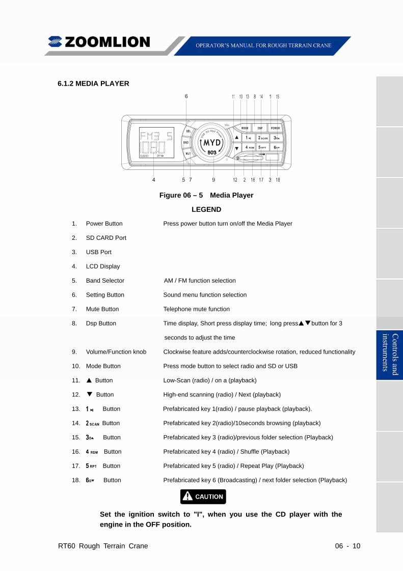
Figure 06 – 5 Media Player
LEGEND
1. Power Button Press power button turn on/off the Media Player
2. SD CARD Port
3. USB Port
4. LCD Display
5. Band Selector AM / FM function selection
6. Setting Button Sound menu function selection
7. Mute Button Telephone mute function
8. Dsp Button Time display, Short press display time; long press▲▼button for 3
seconds to adjust the time
9. Volume/Function knob Clockwise feature adds/counterclockwise rotation, reduced functionality
10. Mode Button Press mode button to select radio and SD or USB
11. ▲ Button Low-Scan (radio) / on a (playback)
12. ▼ Button High-end scanning (radio) / Next (playback)
13. Button Prefabricated key 1(radio) / pause playback (playback).
14. Button Prefabricated key 2(radio)/10seconds browsing (playback)
15. Button Prefabricated key 3 (radio)/previous folder selection (Playback)
16. Button Prefabricated key 4 (radio) / Shuffle (Playback)
17. Button Prefabricated key 5 (radio) / Repeat Play (Playback)
18. Button Prefabricated key 6 (Broadcasting) / next folder selection (Playback)
Set the ignition switch to "I", when you use the CD player with the
engine in the OFF position.
06 - 11 RT60 Rough Terrain Crane
6.2 CONTROLS AND INSTRUMENTS
1 2 3 4 (3) 5 6 7 8 9 10
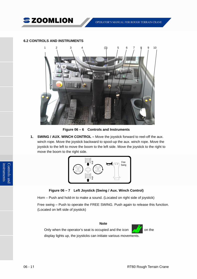
Figure 06 – 6 Controls and Instruments
1. SWING / AUX. WINCH CONTROL – Move the joystick forward to reel-off the aux.
winch rope. Move the joystick backward to spool-up the aux. winch rope. Move the
joystick to the left to move the boom to the left side. Move the joystick to the right to
move the boom to the right side.
FreeSwing
Figure 06 – 7 Left Joystick (Swing / Aux. Winch Control)
Horn – Push and hold-in to make a sound. (Located on right side of joystick)
Free swing – Push to operate the FREE SWING. Push again to release this function.
(Located on left side of joystick)
Note
Only when the operator’s seat is occupied and the icon on the
display lights up, the joysticks can initiate various movements.
RT60 Rough Terrain Crane 06 - 12
2. BOOM EXTEND / RETRACT PEDAL
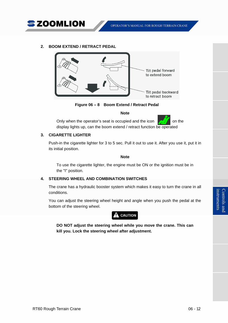
Figure 06 – 8 Boom Extend / Retract Pedal
Note
Only when the operator’s seat is occupied and the icon on the
display lights up, can the boom extend / retract function be operated
3. CIGARETTE LIGHTER
Push-in the cigarette lighter for 3 to 5 sec. Pull it out to use it. After you use it, put it in
its initial position.
Note
To use the cigarette lighter, the engine must be ON or the ignition must be in
the "I" position.
4. STEERING WHEEL AND COMBINATION SWITCHES
The crane has a hydraulic booster system which makes it easy to turn the crane in all
conditions.
You can adjust the steering wheel height and angle when you push the pedal at the
bottom of the steering wheel.
DO NOT adjust the steering wheel while you move the crane. This can
kill you. Lock the steering wheel after adjustment.
06 - 13 RT60 Rough Terrain Crane
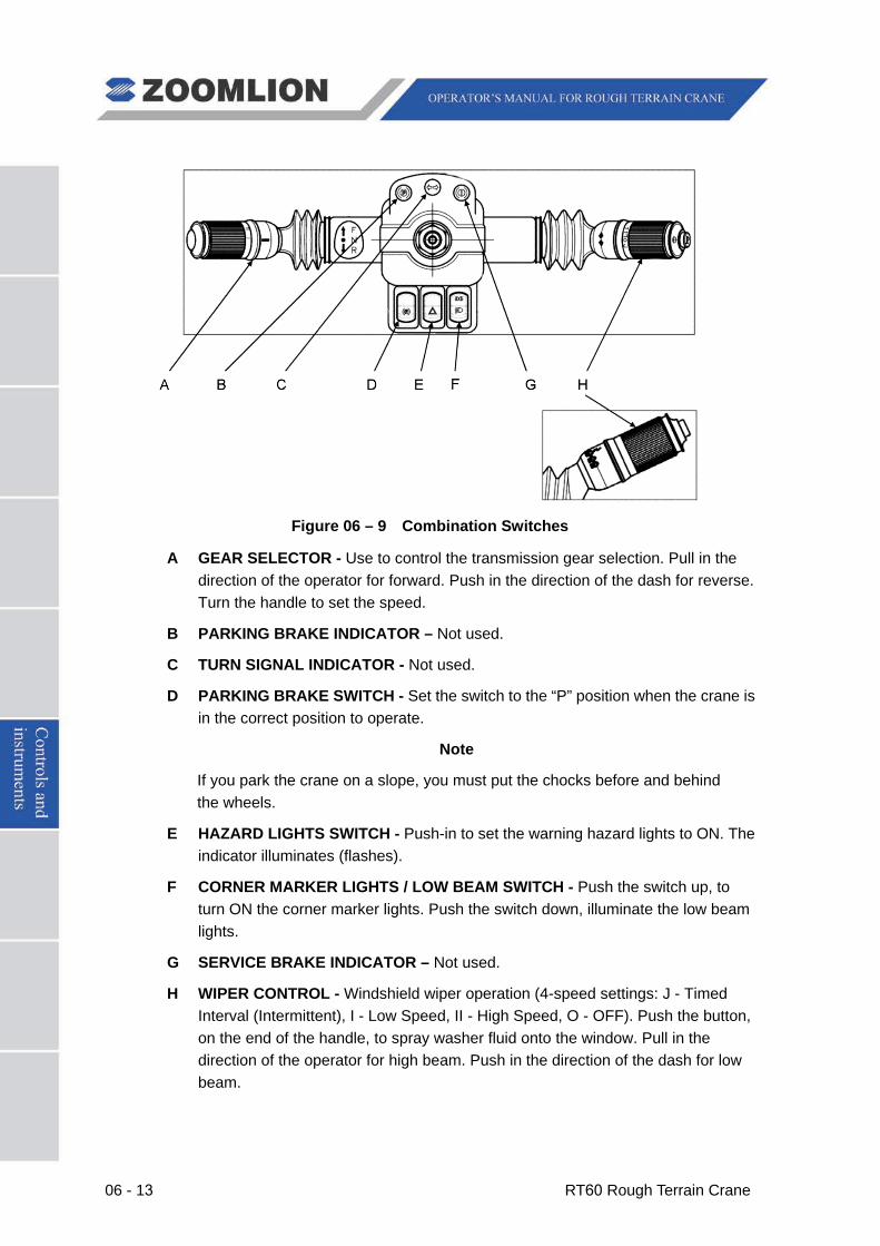
Figure 06 – 9 Combination Switches
A GEAR SELECTOR - Use to control the transmission gear selection. Pull in the direction of the operator for forward. Push in the direction of the dash for reverse. Turn the handle to set the speed.
B PARKING BRAKE INDICATOR – Not used.
C TURN SIGNAL INDICATOR - Not used.
D PARKING BRAKE SWITCH - Set the switch to the “P” position when the crane is in the correct position to operate.
Note
If you park the crane on a slope, you must put the chocks before and behind the wheels.
E HAZARD LIGHTS SWITCH - Push-in to set the warning hazard lights to ON. The indicator illuminates (flashes).
F CORNER MARKER LIGHTS / LOW BEAM SWITCH - Push the switch up, to turn ON the corner marker lights. Push the switch down, illuminate the low beam lights.
G SERVICE BRAKE INDICATOR – Not used.
H WIPER CONTROL - Windshield wiper operation (4-speed settings: J - Timed Interval (Intermittent), I - Low Speed, II - High Speed, O - OFF). Push the button, on the end of the handle, to spray washer fluid onto the window. Pull in the direction of the operator for high beam. Push in the direction of the dash for low beam.
RT60 Rough Terrain Crane 06 - 14
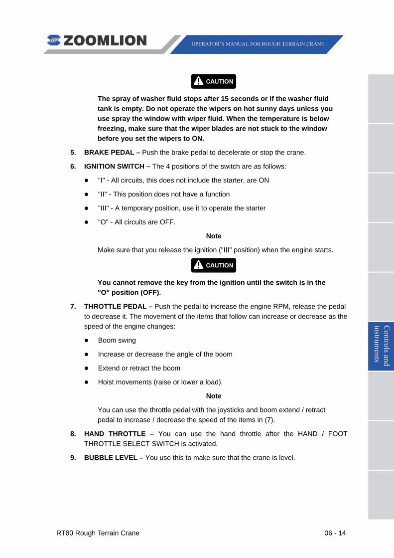
The spray of washer fluid stops after 15 seconds or if the washer fluid tank is empty. Do not operate the wipers on hot sunny days unless you use spray the window with wiper fluid. When the temperature is below freezing, make sure that the wiper blades are not stuck to the window before you set the wipers to ON.
5. BRAKE PEDAL – Push the brake pedal to decelerate or stop the crane.
6. IGNITION SWITCH – The 4 positions of the switch are as follows:
"I" - All circuits, this does not include the starter, are ON
"II" - This position does not have a function
"III" - A temporary position, use it to operate the starter
"O" - All circuits are OFF.
Note
Make sure that you release the ignition ("III" position) when the engine starts.
You cannot remove the key from the ignition until the switch is in the "O" position (OFF).
7. THROTTLE PEDAL – Push the pedal to increase the engine RPM, release the pedal to decrease it. The movement of the items that follow can increase or decrease as the speed of the engine changes:
Boom swing
Increase or decrease the angle of the boom
Extend or retract the boom
Hoist movements (raise or lower a load).
Note
You can use the throttle pedal with the joysticks and boom extend / retract pedal to increase / decrease the speed of the items in (7).
8. HAND THROTTLE – You can use the hand throttle after the HAND / FOOT THROTTLE SELECT SWITCH is activated.
9. BUBBLE LEVEL – You use this to make sure that the crane is level.
06 - 15 RT60 Rough Terrain Crane
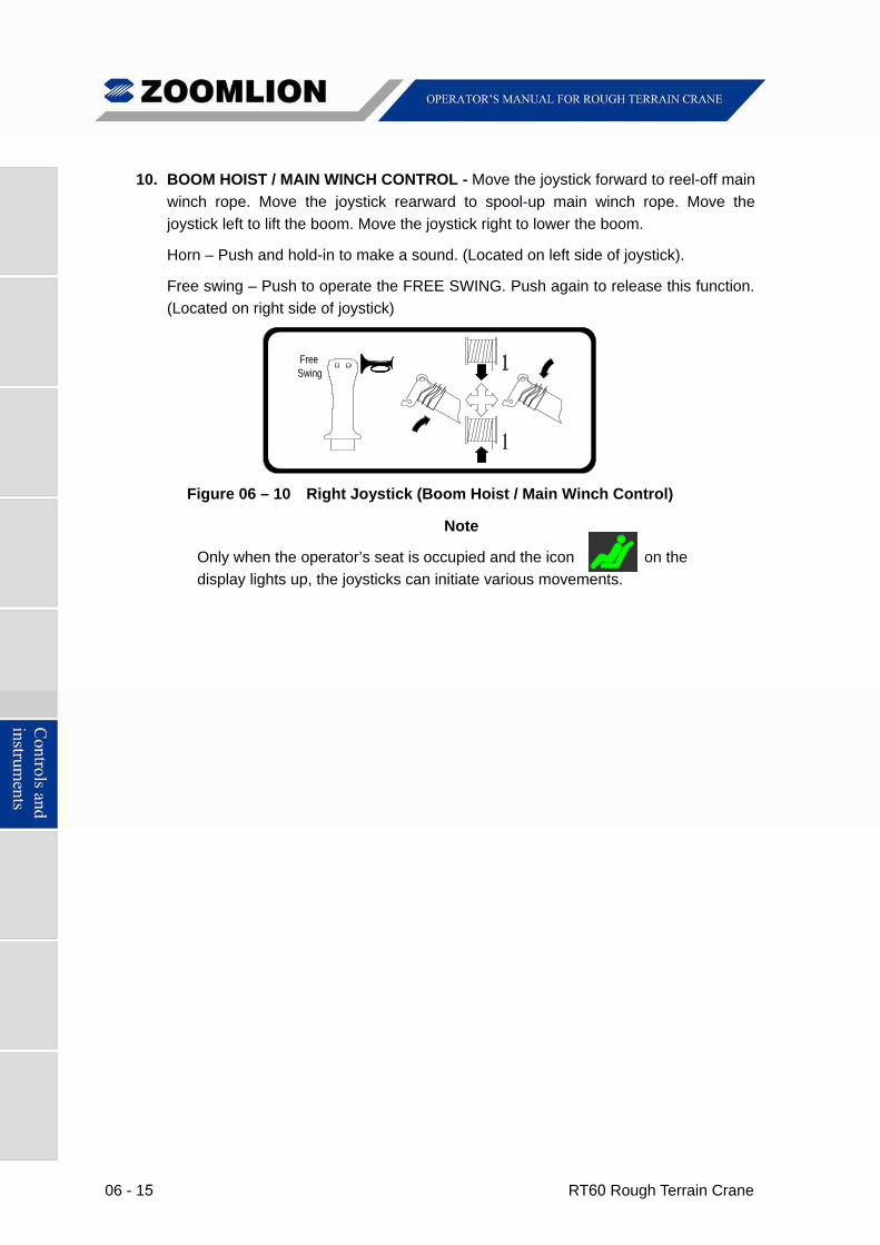
10. BOOM HOIST / MAIN WINCH CONTROL - Move the joystick forward to reel-off main
winch rope. Move the joystick rearward to spool-up main winch rope. Move the
joystick left to lift the boom. Move the joystick right to lower the boom.
Horn – Push and hold-in to make a sound. (Located on left side of joystick).
Free swing – Push to operate the FREE SWING. Push again to release this function.
(Located on right side of joystick)
FreeSwing
Figure 06 – 10 Right Joystick (Boom Hoist / Main Winch Control)
Note
Only when the operator’s seat is occupied and the icon on the
display lights up, the joysticks can initiate various movements.
RT60 Rough Terrain Crane 06 - 16
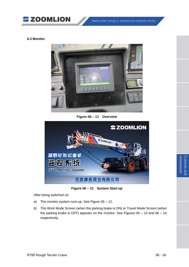
6.3 Monitor
Figure 06 – 11 Overview
Figure 06 – 12 System Start-up
After being switched on:
a) The monitor system runs up. See Figure 06 – 12.
b) The Work Mode Screen (when the parking brake is ON) or Travel Mode Screen (when the parking brake is OFF) appears on the monitor. See Figures 06 – 13 and 06 – 14 respectively.
06 - 17 RT60 Rough Terrain Crane
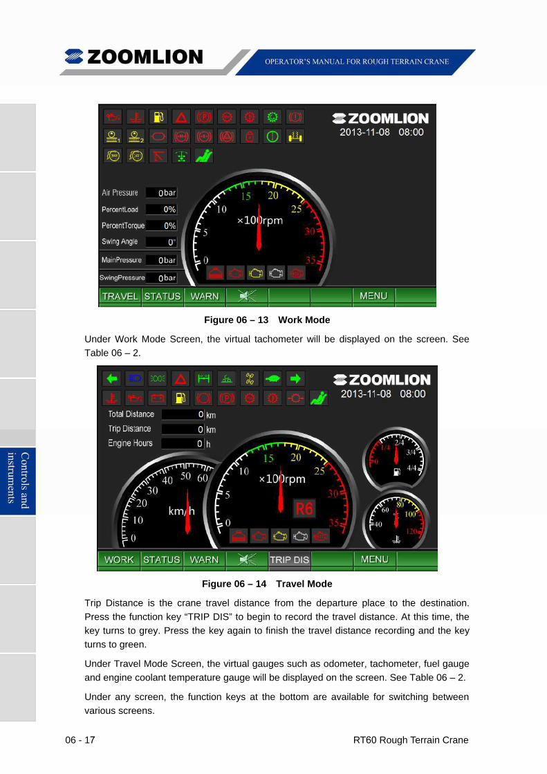
Figure 06 – 13 Work Mode
Under Work Mode Screen, the virtual tachometer will be displayed on the screen. See
Table 06 – 2.
Figure 06 – 14 Travel Mode
Trip Distance is the crane travel distance from the departure place to the destination.
Press the function key “TRIP DIS” to begin to record the travel distance. At this time, the
key turns to grey. Press the key again to finish the travel distance recording and the key
turns to green.
Under Travel Mode Screen, the virtual gauges such as odometer, tachometer, fuel gauge
and engine coolant temperature gauge will be displayed on the screen. See Table 06 – 2.
Under any screen, the function keys at the bottom are available for switching between
various screens.
RT60 Rough Terrain Crane 06 - 18
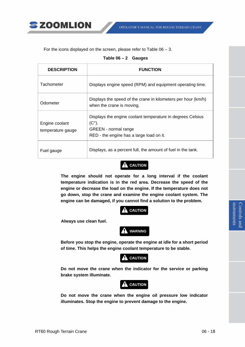
For the icons displayed on the screen, please refer to Table 06 – 3.
Table 06 – 2 Gauges
DESCRIPTION FUNCTION
Tachometer Displays engine speed (RPM) and equipment operating time.
Odometer Displays the speed of the crane in kilometers per hour (km/h) when the crane is moving.
Engine coolant temperature gauge
Displays the engine coolant temperature in degrees Celsius (C°). GREEN - normal range RED - the engine has a large load on it.
Fuel gauge Displays, as a percent full, the amount of fuel in the tank.
The engine should not operate for a long interval if the coolant temperature indication is in the red area. Decrease the speed of the engine or decrease the load on the engine. If the temperature does not go down, stop the crane and examine the engine coolant system. The engine can be damaged, if you cannot find a solution to the problem.
Always use clean fuel.
Before you stop the engine, operate the engine at idle for a short period of time. This helps the engine coolant temperature to be stable.
Do not move the crane when the indicator for the service or parking brake system illuminate.
Do not move the crane when the engine oil pressure low indicator illuminates. Stop the engine to prevent damage to the engine.
06 - 19 RT60 Rough Terrain Crane
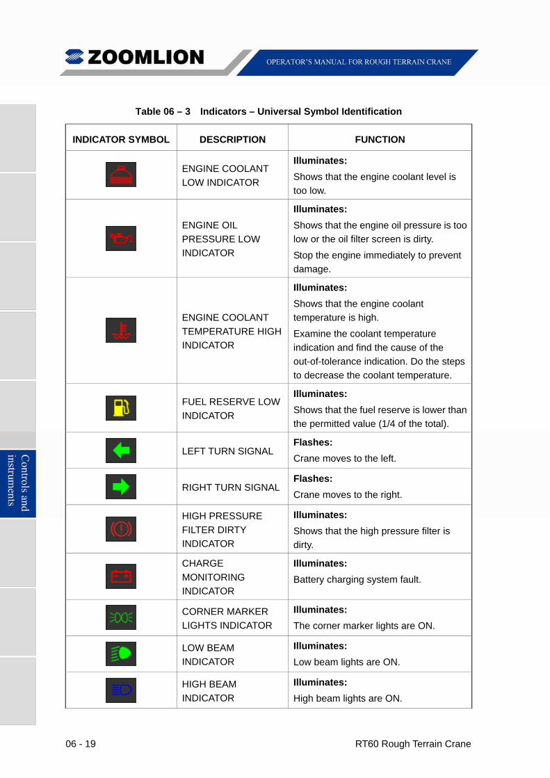
Table 06 – 3 Indicators – Universal Symbol Identification
INDICATOR SYMBOL DESCRIPTION FUNCTION
ENGINE COOLANT
LOW INDICATOR
Illuminates:
Shows that the engine coolant level is
too low.
ENGINE OIL
PRESSURE LOW
INDICATOR
Illuminates:
Shows that the engine oil pressure is too
low or the oil filter screen is dirty.
Stop the engine immediately to prevent
damage.
ENGINE COOLANT
TEMPERATURE HIGH
INDICATOR
Illuminates:
Shows that the engine coolant
temperature is high.
Examine the coolant temperature
indication and find the cause of the
out-of-tolerance indication. Do the steps
to decrease the coolant temperature.
FUEL RESERVE LOW
INDICATOR
Illuminates:
Shows that the fuel reserve is lower than
the permitted value (1/4 of the total).
LEFT TURN SIGNAL
Flashes:
Crane moves to the left.
RIGHT TURN SIGNAL
Flashes:
Crane moves to the right.
HIGH PRESSURE
FILTER DIRTY
INDICATOR
Illuminates:
Shows that the high pressure filter is
dirty.
CHARGE
MONITORING
INDICATOR
Illuminates:
Battery charging system fault.
CORNER MARKER
LIGHTS INDICATOR
Illuminates:
The corner marker lights are ON.
LOW BEAM
INDICATOR
Illuminates:
Low beam lights are ON.
HIGH BEAM
INDICATOR
Illuminates:
High beam lights are ON.
RT60 Rough Terrain Crane 06 - 20
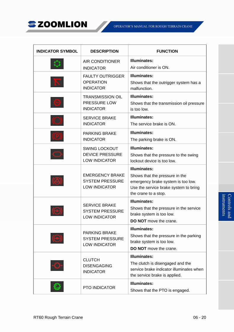
INDICATOR SYMBOL DESCRIPTION FUNCTION
AIR CONDITIONER
INDICATOR
Illuminates:
Air conditioner is ON.
FAULTY OUTRIGGER
OPERATION
INDICATOR
Illuminates:
Shows that the outrigger system has a
malfunction.
TRANSMISSION OIL
PRESSURE LOW
INDICATOR
Illuminates:
Shows that the transmission oil pressure
is too low.
SERVICE BRAKE
INDICATOR
Illuminates:
The service brake is ON.
PARKING BRAKE
INDICATOR
Illuminates:
The parking brake is ON.
SWING LOCKOUT
DEVICE PRESSURE
LOW INDICATOR
Illuminates:
Shows that the pressure to the swing
lockout device is too low.
EMERGENCY BRAKE
SYSTEM PRESSURE
LOW INDICATOR
Illuminates:
Shows that the pressure in the
emergency brake system is too low.
Use the service brake system to bring
the crane to a stop.
SERVICE BRAKE
SYSTEM PRESSURE
LOW INDICATOR
Illuminates:
Shows that the pressure in the service
brake system is too low.
DO NOT move the crane.
PARKING BRAKE
SYSTEM PRESSURE
LOW INDICATOR
Illuminates:
Shows that the pressure in the parking
brake system is too low.
DO NOT move the crane.
CLUTCH
DISENGAGING
INDICATOR
Illuminates:
The clutch is disengaged and the
service brake indicator illuminates when
the service brake is applied.
PTO INDICATOR
Illuminates:
Shows that the PTO is engaged.
06 - 21 RT60 Rough Terrain Crane
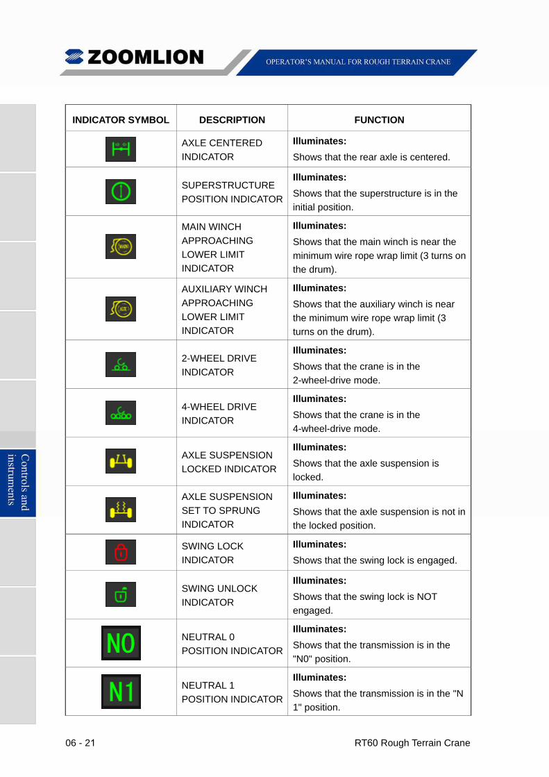
INDICATOR SYMBOL DESCRIPTION FUNCTION
AXLE CENTERED
INDICATOR
Illuminates:
Shows that the rear axle is centered.
SUPERSTRUCTURE
POSITION INDICATOR
Illuminates:
Shows that the superstructure is in the
initial position.
MAIN WINCH
APPROACHING
LOWER LIMIT
INDICATOR
Illuminates:
Shows that the main winch is near the
minimum wire rope wrap limit (3 turns on
the drum).
AUXILIARY WINCH
APPROACHING
LOWER LIMIT
INDICATOR
Illuminates:
Shows that the auxiliary winch is near
the minimum wire rope wrap limit (3
turns on the drum).
2-WHEEL DRIVE
INDICATOR
Illuminates:
Shows that the crane is in the
2-wheel-drive mode.
4-WHEEL DRIVE
INDICATOR
Illuminates:
Shows that the crane is in the
4-wheel-drive mode.
AXLE SUSPENSION
LOCKED INDICATOR
Illuminates:
Shows that the axle suspension is
locked.
AXLE SUSPENSION
SET TO SPRUNG
INDICATOR
Illuminates:
Shows that the axle suspension is not in
the locked position.
SWING LOCK
INDICATOR
Illuminates:
Shows that the swing lock is engaged.
SWING UNLOCK
INDICATOR
Illuminates:
Shows that the swing lock is NOT
engaged.
NEUTRAL 0
POSITION INDICATOR
Illuminates:
Shows that the transmission is in the
"N0" position.
NEUTRAL 1
POSITION INDICATOR
Illuminates:
Shows that the transmission is in the "N
1" position.
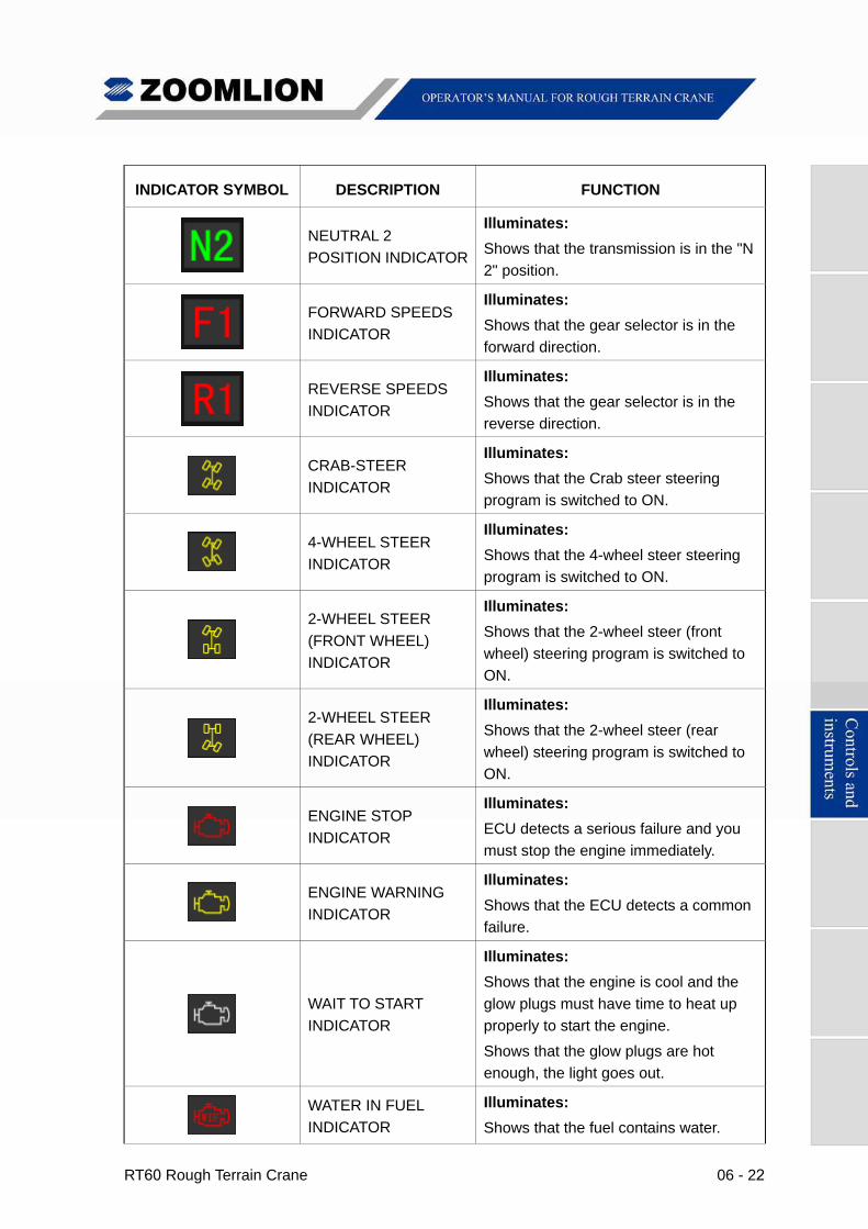
RT60 Rough Terrain Crane 06 - 22
INDICATOR SYMBOL DESCRIPTION FUNCTION
NEUTRAL 2
POSITION INDICATOR
Illuminates:
Shows that the transmission is in the "N
2" position.
FORWARD SPEEDS
INDICATOR
Illuminates:
Shows that the gear selector is in the
forward direction.
REVERSE SPEEDS
INDICATOR
Illuminates:
Shows that the gear selector is in the
reverse direction.
CRAB-STEER
INDICATOR
Illuminates:
Shows that the Crab steer steering
program is switched to ON.
4-WHEEL STEER
INDICATOR
Illuminates:
Shows that the 4-wheel steer steering
program is switched to ON.
2-WHEEL STEER
(FRONT WHEEL)
INDICATOR
Illuminates:
Shows that the 2-wheel steer (front
wheel) steering program is switched to
ON.
2-WHEEL STEER
(REAR WHEEL)
INDICATOR
Illuminates:
Shows that the 2-wheel steer (rear
wheel) steering program is switched to
ON.
ENGINE STOP
INDICATOR
Illuminates:
ECU detects a serious failure and you
must stop the engine immediately.
ENGINE WARNING
INDICATOR
Illuminates:
Shows that the ECU detects a common
failure.
WAIT TO START
INDICATOR
Illuminates:
Shows that the engine is cool and the
glow plugs must have time to heat up
properly to start the engine.
Shows that the glow plugs are hot
enough, the light goes out.
WATER IN FUEL
INDICATOR
Illuminates:
Shows that the fuel contains water.
06 - 23 RT60 Rough Terrain Crane
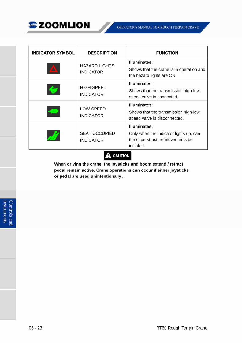
INDICATOR SYMBOL DESCRIPTION FUNCTION
HAZARD LIGHTS
INDICATOR
Illuminates:
Shows that the crane is in operation and
the hazard lights are ON.
HIGH-SPEED
INDICATOR
Illuminates:
Shows that the transmission high-low
speed valve is connected.
LOW-SPEED
INDICATOR
Illuminates:
Shows that the transmission high-low
speed valve is disconnected.
SEAT OCCUPIED
INDICATOR
Illuminates:
Only when the indicator lights up, can
the superstructure movements be
initiated.
When driving the crane, the joysticks and boom extend / retract
pedal remain active. Crane operations can occur if either joysticks
or pedal are used unintentionally .
RT60 Rough Terrain Crane 06 - 24
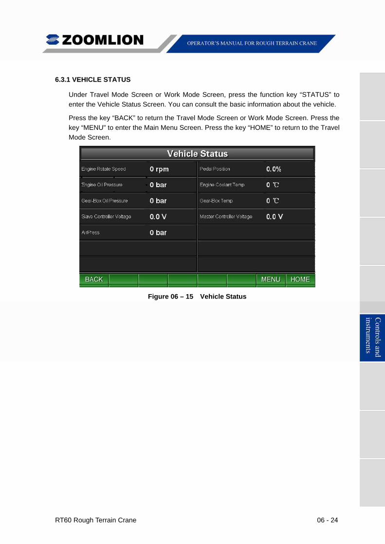
6.3.1 VEHICLE STATUS
Under Travel Mode Screen or Work Mode Screen, press the function key “STATUS” to
enter the Vehicle Status Screen. You can consult the basic information about the vehicle.
Press the key “BACK” to return the Travel Mode Screen or Work Mode Screen. Press the
key “MENU" to enter the Main Menu Screen. Press the key “HOME” to return to the Travel
Mode Screen.
Figure 06 – 15 Vehicle Status
06 - 25 RT60 Rough Terrain Crane
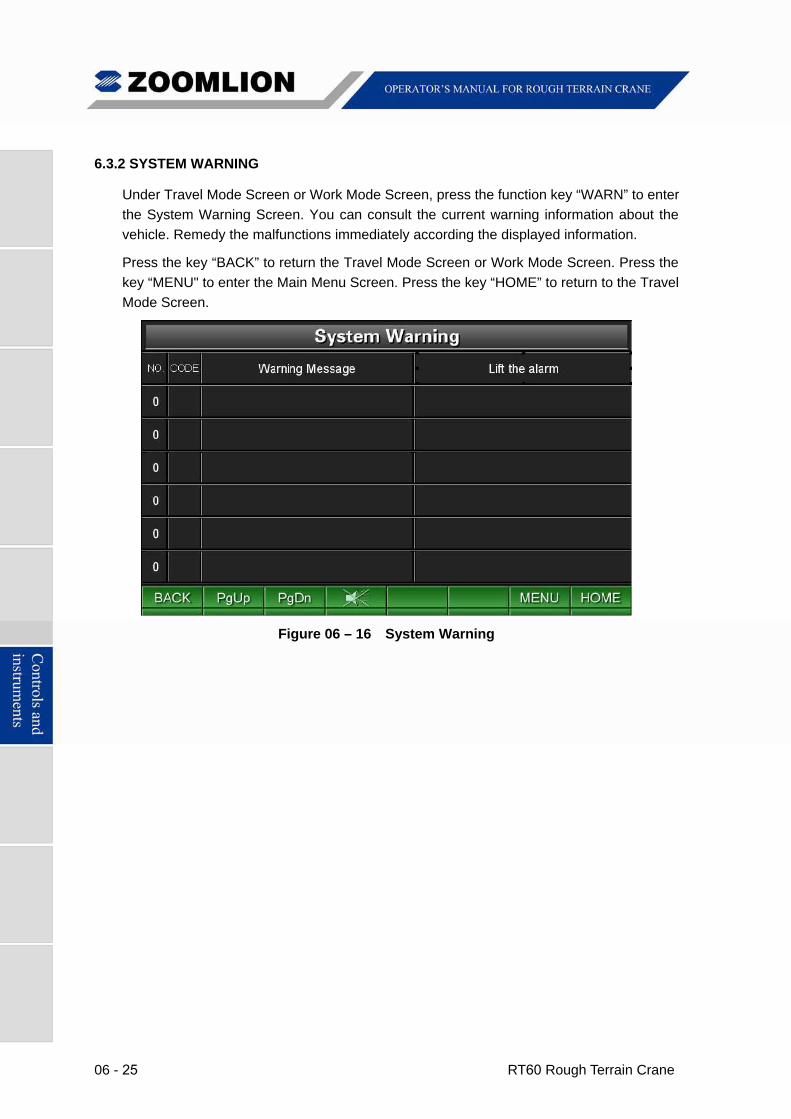
6.3.2 SYSTEM WARNING
Under Travel Mode Screen or Work Mode Screen, press the function key “WARN” to enter
the System Warning Screen. You can consult the current warning information about the
vehicle. Remedy the malfunctions immediately according the displayed information.
Press the key “BACK” to return the Travel Mode Screen or Work Mode Screen. Press the
key “MENU" to enter the Main Menu Screen. Press the key “HOME” to return to the Travel
Mode Screen.
Figure 06 – 16 System Warning
RT60 Rough Terrain Crane 06 - 26
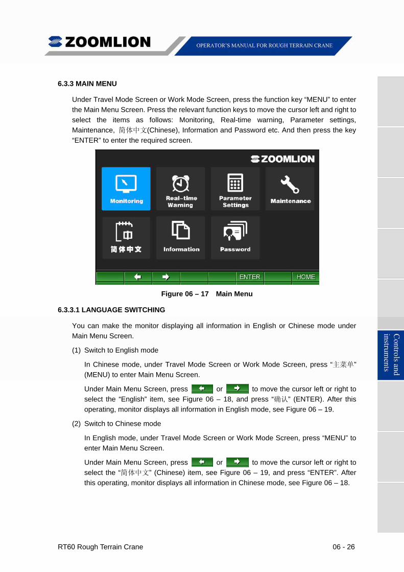
6.3.3 MAIN MENU
Under Travel Mode Screen or Work Mode Screen, press the function key “MENU” to enter
the Main Menu Screen. Press the relevant function keys to move the cursor left and right to
select the items as follows: Monitoring, Real-time warning, Parameter settings,
Maintenance, 简体中文(Chinese), Information and Password etc. And then press the key
“ENTER” to enter the required screen.
Figure 06 – 17 Main Menu
6.3.3.1 LANGUAGE SWITCHING
You can make the monitor displaying all information in English or Chinese mode under
Main Menu Screen.
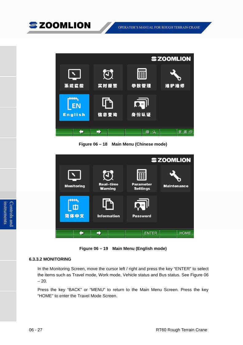
(1) Switch to English mode
In Chinese mode, under Travel Mode Screen or Work Mode Screen, press “主菜单”
(MENU) to enter Main Menu Screen.
Under Main Menu Screen, press or to move the cursor left or right to
select the “English” item, see Figure 06 – 18, and press “确认” (ENTER). After this
operating, monitor displays all information in English mode, see Figure 06 – 19.
(2) Switch to Chinese mode
In English mode, under Travel Mode Screen or Work Mode Screen, press “MENU” to
enter Main Menu Screen.
Under Main Menu Screen, press or to move the cursor left or right to
select the “简体中文” (Chinese) item, see Figure 06 – 19, and press “ENTER”. After
this operating, monitor displays all information in Chinese mode, see Figure 06 – 18.
06 - 27 RT60 Rough Terrain Crane
Figure 06 – 18 Main Menu (Chinese mode)
Figure 06 – 19 Main Menu (English mode)
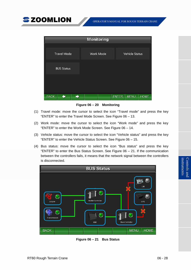
6.3.3.2 MONITORING
In the Monitoring Screen, move the cursor left / right and press the key “ENTER” to select
the items such as Travel mode, Work mode, Vehicle status and Bus status. See Figure 06
– 20.
Press the key “BACK” or “MENU” to return to the Main Menu Screen. Press the key
“HOME" to enter the Travel Mode Screen.
RT60 Rough Terrain Crane 06 - 28
Figure 06 – 20 Monitoring
(1) Travel mode: move the cursor to select the icon “Travel mode” and press the key
“ENTER” to enter the Travel Mode Screen. See Figure 06 – 13.
(2) Work mode: move the cursor to select the icon “Work mode” and press the key
“ENTER” to enter the Work Mode Screen. See Figure 06 – 14.
(3) Vehicle status: move the cursor to select the icon “Vehicle status” and press the key
“ENTER” to enter the Vehicle Status Screen. See Figure 06 – 15.
(4) Bus status: move the cursor to select the icon “Bus status” and press the key
“ENTER” to enter the Bus Status Screen. See Figure 06 – 21. If the communication
between the controllers fails, it means that the network signal between the controllers
is disconnected.
Figure 06 – 21 Bus Status
06 - 29 RT60 Rough Terrain Crane
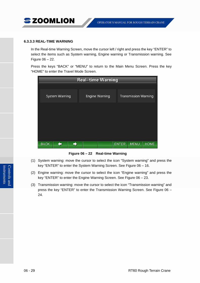
6.3.3.3 REAL-TIME WARNING
In the Real-time Warning Screen, move the cursor left / right and press the key “ENTER” to
select the items such as System warning, Engine warning or Transmission warning. See
Figure 06 – 22.
Press the keys “BACK” or “MENU” to return to the Main Menu Screen. Press the key
“HOME" to enter the Travel Mode Screen.
Figure 06 – 22 Real-time Warning
(1) System warning: move the cursor to select the icon “System warning” and press the
key “ENTER” to enter the System Warning Screen. See Figure 06 – 16.
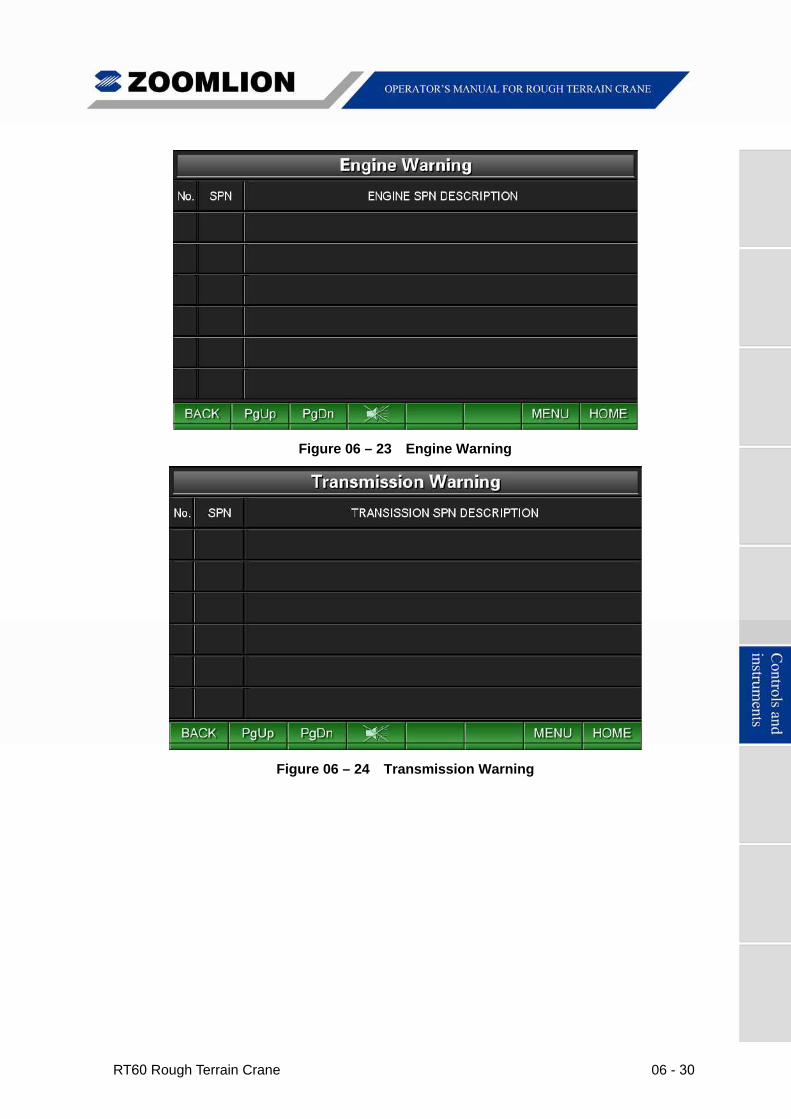
(2) Engine warning: move the cursor to select the icon “Engine warning” and press the
key “ENTER” to enter the Engine Warning Screen. See Figure 06 – 23.
(3) Transmission warning: move the cursor to select the icon “Transmission warning” and
press the key “ENTER” to enter the Transmission Warning Screen. See Figure 06 –
24.
RT60 Rough Terrain Crane 06 - 30
Figure 06 – 23 Engine Warning
Figure 06 – 24 Transmission Warning
06 - 31 RT60 Rough Terrain Crane
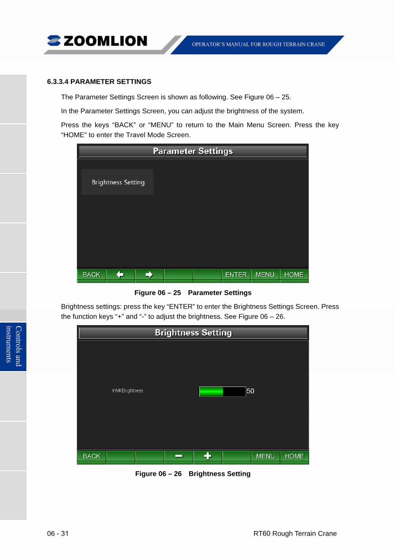
6.3.3.4 PARAMETER SETTINGS
The Parameter Settings Screen is shown as following. See Figure 06 – 25.
In the Parameter Settings Screen, you can adjust the brightness of the system.
Press the keys “BACK” or “MENU” to return to the Main Menu Screen. Press the key
“HOME" to enter the Travel Mode Screen.
Figure 06 – 25 Parameter Settings
Brightness settings: press the key “ENTER” to enter the Brightness Settings Screen. Press
the function keys “+” and “-” to adjust the brightness. See Figure 06 – 26.
Figure 06 – 26 Brightness Setting
RT60 Rough Terrain Crane 06 - 32
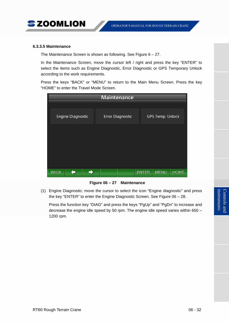
6.3.3.5 Maintenance
The Maintenance Screen is shown as following. See Figure 6 – 27.
In the Maintenance Screen, move the cursor left / right and press the key “ENTER” to
select the items such as Engine Diagnostic, Error Diagnostic or GPS Temporary Unlock
according to the work requirements.
Press the keys “BACK” or “MENU” to return to the Main Menu Screen. Press the key
“HOME" to enter the Travel Mode Screen.
Figure 06 – 27 Maintenance
(1) Engine Diagnostic: move the cursor to select the icon “Engine diagnostic” and press
the key “ENTER” to enter the Engine Diagnostic Screen. See Figure 06 – 28.
Press the function key “DIAG” and press the keys “PgUp” and “PgDn” to increase and
decrease the engine idle speed by 50 rpm. The engine idle speed varies within 650 –
1200 rpm.
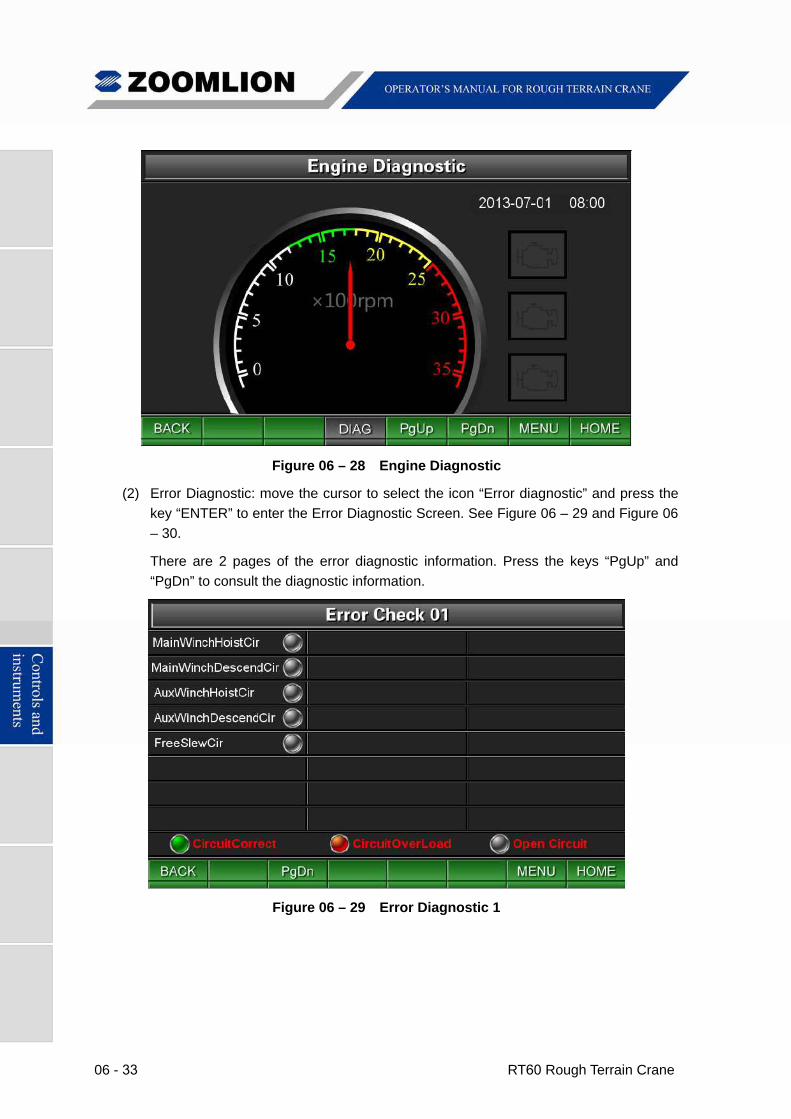
06 - 33 RT60 Rough Terrain Crane
Figure 06 – 28 Engine Diagnostic
(2) Error Diagnostic: move the cursor to select the icon “Error diagnostic” and press the
key “ENTER” to enter the Error Diagnostic Screen. See Figure 06 – 29 and Figure 06
– 30.
There are 2 pages of the error diagnostic information. Press the keys “PgUp” and
“PgDn” to consult the diagnostic information.
Figure 06 – 29 Error Diagnostic 1
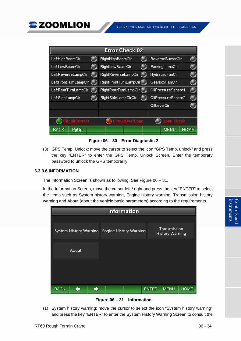
RT60 Rough Terrain Crane 06 - 34
Figure 06 – 30 Error Diagnostic 2
(3) GPS Temp. Unlock: move the cursor to select the icon “GPS Temp. unlock” and press
the key “ENTER” to enter the GPS Temp. Unlock Screen. Enter the temporary
password to unlock the GPS temporarily.
6.3.3.6 INFORMATION
The Information Screen is shown as following. See Figure 06 – 31.
In the Information Screen, move the cursor left / right and press the key “ENTER” to select
the items such as System history warning, Engine history warning, Transmission history
warning and About (about the vehicle basic parameters) according to the requirements.
Figure 06 – 31 Information
(1) System history warning: move the cursor to select the icon “System history warning”
and press the key “ENTER” to enter the System History Warning Screen to consult the
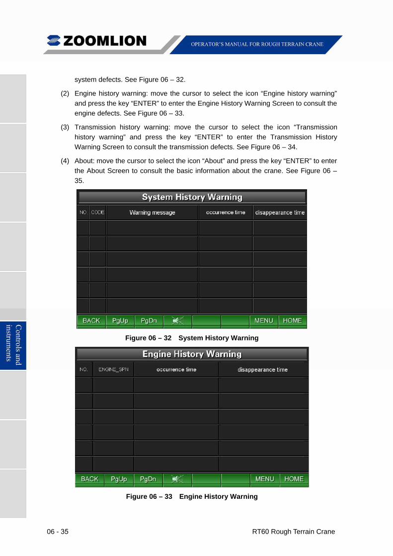
06 - 35 RT60 Rough Terrain Crane
system defects. See Figure 06 – 32.
(2) Engine history warning: move the cursor to select the icon “Engine history warning”
and press the key “ENTER” to enter the Engine History Warning Screen to consult the
engine defects. See Figure 06 – 33.
(3) Transmission history warning: move the cursor to select the icon “Transmission
history warning” and press the key “ENTER” to enter the Transmission History
Warning Screen to consult the transmission defects. See Figure 06 – 34.
(4) About: move the cursor to select the icon “About” and press the key “ENTER” to enter
the About Screen to consult the basic information about the crane. See Figure 06 –
35.
Figure 06 – 32 System History Warning
Figure 06 – 33 Engine History Warning
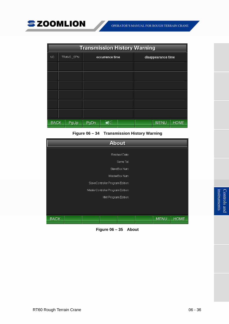
RT60 Rough Terrain Crane 06 - 36
Figure 06 – 34 Transmission History Warning
Figure 06 – 35 About
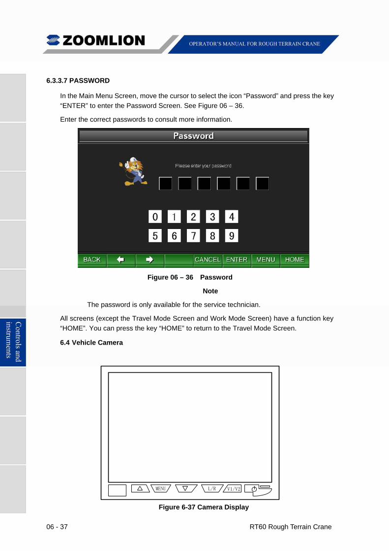
06 - 37 RT60 Rough Terrain Crane
6.3.3.7 PASSWORD
In the Main Menu Screen, move the cursor to select the icon “Password” and press the key
“ENTER” to enter the Password Screen. See Figure 06 – 36.
Enter the correct passwords to consult more information.
Figure 06 – 36 Password
Note
The password is only available for the service technician.
All screens (except the Travel Mode Screen and Work Mode Screen) have a function key
“HOME”. You can press the key “HOME” to return to the Travel Mode Screen.
6.4 Vehicle Camera
Figure 6-37 Camera Display
V1/V2MENU L/R
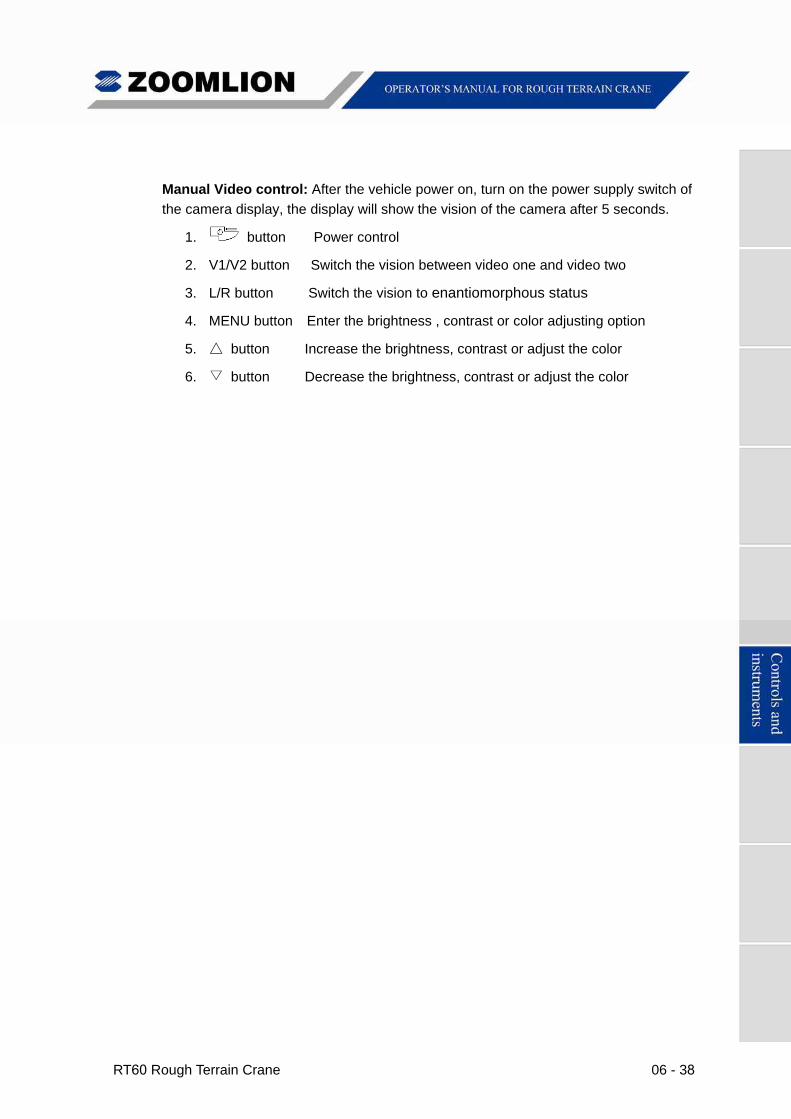
RT60 Rough Terrain Crane 06 - 38
Manual Video control: After the vehicle power on, turn on the power supply switch of
the camera display, the display will show the vision of the camera after 5 seconds.
1. button Power control
2. V1/V2 button Switch the vision between video one and video two
3. L/R button Switch the vision to enantiomorphous status
4. MENU button Enter the brightness , contrast or color adjusting option
5. △ button Increase the brightness, contrast or adjust the color
6. ▽ button Decrease the brightness, contrast or adjust the color

RT60 Rough Terrain Crane 07 - 1
7.1 SAFETY EQUIPMENT
Anti-Two Block System
Examine the anti-two block switches on the boom, the jib and auxiliary sheave heads for
damage. Make sure that the switch weights operate correctly and they are on the lift
cable in the correct position. Examine the electrical equipment and wires that attach to
the cable reel. Do an inspection of the wires along the length of the cable. Look for
indications of wear, damage or incorrect installation. Make sure that the tension on the
spring-loaded cable reel is correct and that the reel turns freely.
Note
When you do a check of the anti-two block switch function, you must move the
anti-two block weight with the hook block.
Rated Capacity Indicator
When the actual load is near the rated one, it sends out acoustic sound. You can only do
safe crane movements that are on the screen at this time. Move the load into a permitted
condition to stop alarms and continue correct crane operation. For details, please refer to
Rated Capacity Indicator Manual.
Emergency Stop
(1) You can find the emergency stop button on the lower left side of the dash.
(2) When you push the button, all crane operations immediately STOP (includes the
engine). Turn the button clockwise to release it and continue usual crane operation.
(3) Only use the EMERGENCY STOP BUTTON in a clear emergency!
3rd Wrap
When there are only 3 wraps of wire rope remaining on the winch, the winch (main or
auxiliary) does not turn. When this occurs, you can only do “Boom Retract” and “Winch
up” operations.
Seat Occupied Indicator
(1) This indicator illuminates when the seat switch is activated by sitting in the operator
seat.
(2) The seat switch controls the functions of the left and right joystick as well as the
boom telescoping extend/retract foot pedal.
(3) Only when the operator's seat is occupied and the icon on the display is lit
will the crane functions be active (via joystick and telescoping pedal).
When driving the crane, the joysticks and boom extend/retract pedal
remain active. Crane operations can occur if either joysticks or pedal are
used unintentionally.
Caution
07 - 2 RT60 Rough Terrain Crane
7. 2 STARTING THE ENGINE
Start the engine only after the inspection has been completed. At ambient temperature over 0℃ (32℉), follow the starting procedure below:
a) Move the transmission shift lever to the neutral position;
b) Put the parking brake switch in the “ON” position;
c) Turn the ignition switch to the “ON” position;
d) Turn the ignition switch to the “START” position to start the engine.
Release the ignition switch key as soon as the engine starts. If the engine stalls during the start-up procedure, allow the engine to stop running before restarting the starter.
Do not engage the starter motor for more than 15 seconds at a time. Should the engine fail to start within 15 seconds, allow the starter motor to cool for 2 minutes before attempting to start the engine again.
Once the engine is started, check the gauges for proper readings. If the gauges do not register normal readings, stop the engine and determine the cause. Avoid full Throttle operation when the engine is cold. Always allow the engine to reach normal operating temperature before commencing operations.
7. 3 OPERATING THE ENGINE
When the engine reaches operating temperature, operations may begin. While the engine is running, check the gauges at frequent intervals and be alert for any abnormal engine sounds or faulty engine performance.
When idling for extended periods, maintain an idle speed sufficient to prevent the battery from being discharged. Keeping the battery in a fully charged state is important for starting the engine.
Throttle down to half speed or slower with no load for at least 5 minutes before stopping. This gives the engine a chance to cool off gradually before it is stopped.
This cool down period is extremely critical on machines equipped with turbocharged engines due to the excessive build up of heat during normal load operations.
Consult the engine manufacturer’s manual for further operating instructions.
7. 4 COLD WEATHER STARTING
At very low temperatures, when the engine is difficult to start, an optional flame starting device is very important to help the normal engine start. Please contact Zoomlion Service Department if you want to select a flame starting device for your crane.
Note
RT60 Rough Terrain Crane 07 - 3
7. 5 STARTING OFF AND PARKING OPERATION
STARTING OFF OPERATION
After finishing the preparation for driving, start the vehicle in the following steps:
a) Depress the brake pedal;
b) Deactivate parking brake;
c) Move the transmission shift lever to the 1st
d) Release the brake pedal gradually and start to drive.
gear position;
Ensure the brake pressure is sufficient when starting off the vehicle. Otherwise, accident may occur!
PARKING OPERATION
a) Depress brake pedal gently to decelerate the vehicle, meanwhile downshift the transmission to F1 position;
b) When the vehicle is driving at low speed, depress the brake pedal completely to stop the vehicle at the specified place;
c) Turn the parking brake switch to stage “P” and move the transmission shift lever to "N" position;
Never depress brake pedal violently and completely except in a clear emergency during driving.
When the “Crab steer” or “4-wheel steer” steering program is switched on, center the rear axles before stopping the vehicle.
d) Run the engine at idle speed for several minutes to cool down the engine gradually;
e) Keep the engine electrified for about 30 seconds after engine shutdown in order to save the running data of ECU. And then turn the ignition switch to stage “0” and pull it out;
If the battery master switch is activated for a long time after the crane is parked, electricity consumption of battery, circuit breakdown or accident may occur.
f) When the vehicle is being parked on a slope, wheels must be chocked;
g) Hazard lights must be turned on when parking the vehicle at night (special situations are excluded) to avoid being rear collision by other vehicles.
Hazard lights also can be illuminated when the battery and engine are disconnected.
Caution
Caution
Caution
Caution
Warning
07 - 4 RT60 Rough Terrain Crane
7. 6 ECONOMICAL DRIVING
Economical driving which can save fuel and prolong service lives of tires must follow the items below:
a) Develop good driving habits;
b) Do not unnecessarily run the engine at high speed. Shift the transmission into high gear as much as possible during driving. Shift the transmission into low gear only when the engine RPM is unstable during driving;
c) Depress and release the throttle pedal gently. Avoid sharp turning, jackrabbit starting and emergency braking except in a clear emergency. Thus, it can not only ensure safety but also reduce fuel consumption;
d) Keep driving at medium speed (drive at a speed of 3/4 of the max. driving speed in normal conditions), so that fuel can be burnt fully and the displacement and fuel consumption can be reduced;
e) Advance gearshift is necessary before accelerating;
f) Keep coolant temperature varying from 70℃ to 95℃ during driving;
Excessively high or low engine coolant temperature will impair the engine performance.
g) Check tire pressure frequently to ensure the crane drives with normal tire pressure;
If the tire pressure is excessively low, the rolling resistance, tire abrasion as well as fuel consumption will be increased.
h) Correctly use air conditioning system;
i) Choose proper fuel and lubricating oil;
j) Maintain the vehicle regularly.
Caution
Caution

RT60 Rough Terrain Crane 07 - 5
7. 7 STEERING OPERATION
The vehicle adopts the hydraulic booster steering system which ensures the safe and reliable steering movement.
Pay attention to the following items during steering:
a) Look around before steering, and then operate the steering wheel after ensuring everything is OK;
b) If necessary, shift the transmission to lower gear to decelerate during steering;
c) If steering is not enough, decelerate the vehicle gradually and simultaneously operate the steering wheel in the same direction;
d) If steering is too much, decelerate the vehicle and simultaneously operate the steering wheel in the reverse direction as soon as possible;
Do not turn the steering wheel in one direction too quickly except in an emergency. Turn smoothly to keep crane laterally stable. Once the steering is complete, turn the steering wheel to the neutral position gently and immediately to avoid making the crane unstable.
e) In sharp turning, decelerate the vehicle and shift the transmission into low gear.
Caution
07 - 6 RT60 Rough Terrain Crane
7. 8 BRAKING OPERATION
SERVICE BRAKE
Apply the service brake as follows under normal condition:
a) Depress the brake pedal half when there is about 82 – 115 ft (25 – 35 m) away from the specified stopping location;
b) Release the brake pedal gradually (about 1/3 - 1/2 of the applied pedal stroke) when there is 16 – 20 ft (5 – 6 m) away from the specified stopping location. As approaching the stopping location, depress the brake pedal completely to stop the vehicle at the specified location.
EMERGENCY BRAKE
In an emergency, depress the brake pedal quickly and completely to stop the vehicle immediately. At this time, the crane may lurch forward, so you must be careful.
If emergency brake is applied frequently, the abrasion of tire and friction lining will be increased, and the service life of each part will be shortened. Applying emergency brake should only be permitted in a clear emergency. Operate with extreme caution in rainy days or on frozen road.
POINTS FOR ATTENTION DURING BRAKING
a) Apply brake smoothly to avoid uncontrolled lurching. Use emergency braking only in emergency situations;
b) If the service brake indicator does not light up when the brake pedal is depressed, stop the vehicle right away. It may be caused by decreased braking performance because of hydraulic oil leakage. Please contact Zoomlion service station in your area;
c) The vehicle adopts dual-circuit brake system. If one line of the brake system fails, the other could still work normally, which greatly enhance working safety. If you suspect brakes are not working properly, contact Zoomlion service station in your area.
If the tire blows out suddenly during driving, don’t depress the brake pedal immediately. Hold the steering wheel carefully to control the driving direction and release the throttle pedal immediately to decelerate the vehicle until it stops in a safe place.
Warning
Caution
RT60 Rough Terrain Crane 07 - 7
7. 9 TRANSMISSION OPERATION
The transmission is hydraulically driven and power shifted. Shifting method is as follows:
a) The transmission is divided into high gear and low gear ranges. The low gear range is in manual shifting mode and the vehicle is started in the 1st
b) When shifting, the transmission shift lever must be shifted in position;
gear position. The high gear range is in automatic shifting mode and the vehicle can be started at any gear position;
c) When there is abnormal noise in the transmission or it is difficult to operate the steering wheel, bring the vehicle to a standstill and rectify it at once according to the Transmission Maintenance and Service Manual;
d) The transmission shift lever should be moved to “N” position when parking the vehicle;
e) Check the transmission oil level when the vehicle is stopped and the engine is running at idle speed.
The oil temperature of transmission should be between 180 – 200℉ (82 – 93℃) for normal operation.
When the oil temperature exceeds 250℉ (121.1℃), stop the vehicle immediately to cool down: move the transmission shift lever to “N” position and keep the engine RPM within 1000 – 1200 rpm, then the oil temperature will decrease immediately.
It is forbidden to turn off the engine when the transmission gear oil temperature is excessively high.
It is forbidden to drive the vehicle when the transmission oil pressure is lower than 240 psi. Excessively low oil pressure may result in clutch skid, thus shorten the service life of clutch.
During driving, do not shift between forward gear and reverse gear. It is forbidden to make the vehicle glide forward by its inertia when the transmission is moved to the neutral position.
Warning
Caution
Caution

07 - 8 RT60 Rough Terrain Crane
7. 10 TOWING
The tow coupling may be damaged when towing the vehicle with the tow coupling at high speed suddenly.
If the vehicle is to be towed, it will be necessary to run the engine at idle speed to lubricate the transmission clutches, and disconnect the drive shafts for front and rear axles.
If the engine cannot be run, the vehicle is not permitted to be towed.
7. 11 PTO OPERATION
The function of PTO is to transmit engine power to the oil pump to carry out various movements via hydraulic system.
POINTS FOR ATTENTION BEFORE OPEARTION:
Ensure the follow prerequisites are met before engaging the PTO:
a) Engine must be turned off;
b) The joysticks in the cab should be set in neutral position;
c) The outrigger switches should be placed in neutral position;
d) The transmission shift lever should be moved to neutral position;
e) The parking brake of chassis should be activated.
Warning
Caution
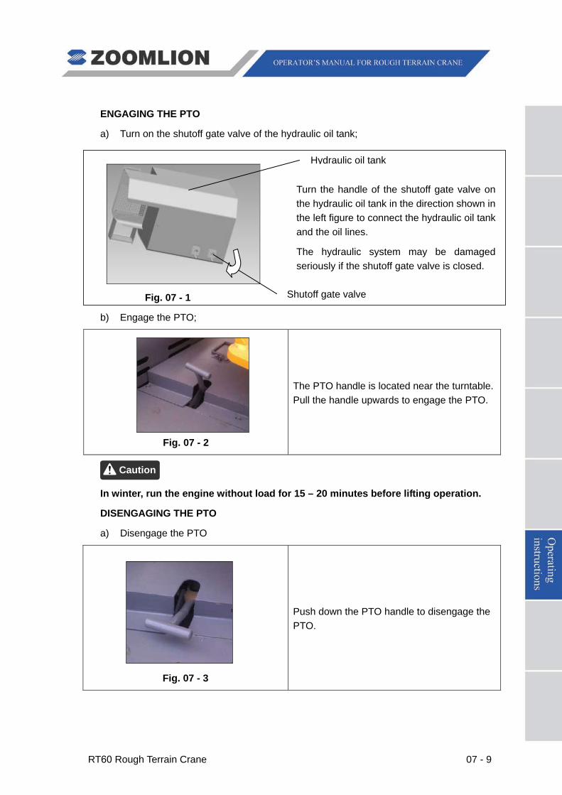
RT60 Rough Terrain Crane 07 - 9
ENGAGING THE PTO
a) Turn on the shutoff gate valve of the hydraulic oil tank;
Turn the handle of the shutoff gate valve on the hydraulic oil tank in the direction shown in the left figure to connect the hydraulic oil tank and the oil lines.
The hydraulic system may be damaged seriously if the shutoff gate valve is closed.
Fig. 07 - 1
b) Engage the PTO;
Fig. 07 - 2
The PTO handle is located near the turntable. Pull the handle upwards to engage the PTO.
In winter, run the engine without load for 15 – 20 minutes before lifting operation.
DISENGAGING THE PTO
a) Disengage the PTO
Fig. 07 - 3
Push down the PTO handle to disengage the PTO.
Caution
Shutoff gate valve
Hydraulic oil tank
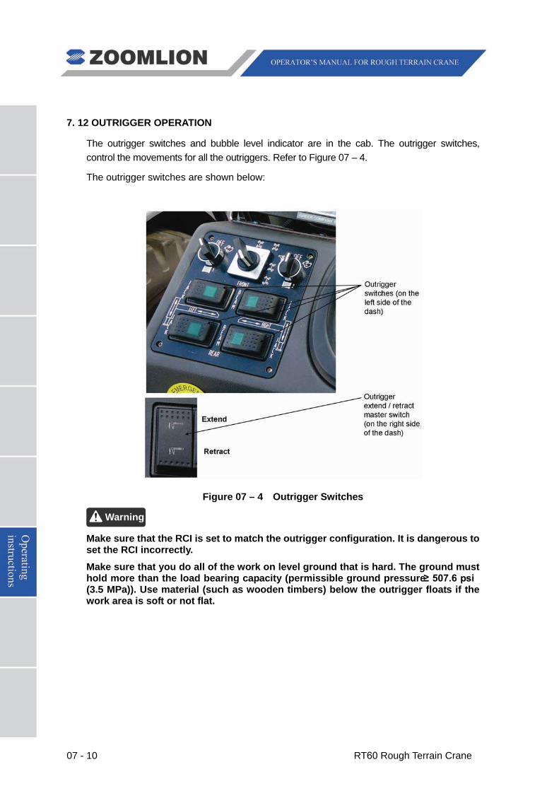
07 - 10 RT60 Rough Terrain Crane
7. 12 OUTRIGGER OPERATION
The outrigger switches and bubble level indicator are in the cab. The outrigger switches, control the movements for all the outriggers. Refer to Figure 07 – 4.
The outrigger switches are shown below:
Figure 07 – 4 Outrigger Switches
Make sure that the RCI is set to match the outrigger configuration. It is dangerous to set the RCI incorrectly.
Make sure that you do all of the work on level ground that is hard. The ground must hold more than the load bearing capacity (permissible ground pressure ≥ 507.6 psi (3.5 MPa)). Use material (such as wooden timbers) below the outrigger floats if the work area is soft or not flat.
Warning
RT60 Rough Terrain Crane 07 - 11
EXTEND THE OUTRIGGERS
a) Remove the outrigger beam retaining pin.
b) Push and hold 2 or 4 outrigger switches to the “BEAM” position.
1 Push and hold the outrigger extend / retract master switch to the “EXTEND” position.
2 After the outriggers move to the “FULLY” or “INTERMEDIATELY” marks, release the master switch. The switch moves to the neutral position automatically.
c) After the 4 outrigger beams extend to the correct positions, push and hold the 2 front (or rear) outrigger switches to the “JACK” position.
1 Push and hold the outrigger extend / retract master switch to the “EXTEND” position.
2 After the 4 outriggers hold the weight of the crane (wheels off the ground), release the master switch. The switch moves to the neutral position automatically.
d) Make the crane level.
1 Look at the bubble level to tell if the crane is at level.
2 If the bubble indicator does not show a level indication, you can move each outrigger to make the crane level.
e) For example:
If the crane is low on the right front, do the steps that follow:
1 Push the right front outrigger switch to the “JACK” position.
2 Push the outrigger extend / retract master switch to the “EXTEND” position at the same time.
3 Monitor the bubble indictor. When the bubble is at the correct position, release the switches.
f) Install the outrigger retaining pins.
RETRACT THE OUTRIGGERS
Retract the boom and attach it to the support before you retract the outriggers.
a) Remove the outrigger beam retaining pins.
b) Push and hold 2 front (or rear) outrigger switches to the “JACK” position.
1 Push the outrigger extend / retract master switch to the “RETRACT” position at the same time.
2 After the 2 front (or rear) outrigger jacks fully retract, release the master switch.
Warning
07 - 12 RT60 Rough Terrain Crane
The switch moves to the neutral position automatically.
3 Do this step until all 2 front (or rear) outrigger jacks are retracted.
c) Push an outrigger switch (1 of 4) to the “BEAM” position.
1 Push the outrigger extend / retract master switch to the “RETRACT” position at the same time.
2 After the outrigger retracts fully, release the master switch. The switch moves to the neutral position automatically.
3 Do this step until all 4 outriggers are retracted.
d) Install the outrigger retaining pins.
INSTALL AND REMOVE THE OUTRIGGER FLOATS
a) Installation
Before you extend the outriggers, remove the socket pin from the outrigger floats and pull out the outrigger floats. When the hole aligns with the vertical cylinder, install the socket pin.
b) Removal
After you fully retract the outriggers, remove the socket pin and push in the outrigger float until it in the correct position. Install the socket pins.
Before you move the outriggers, make sure that there is clearance to prevent injury to personnel or damage to the crane and other objects.
Do not move the outriggers if you have a load off the ground.
You can adjust the speed (slow or fast) of the outriggers movement (extend or retract) by the engine RPM (increase or decrease).
Make sure that you install the outrigger floats before you move the outriggers.
Make sure that you remove the retaining pins before you extend or retract the outrigger beams. After the outrigger beams are in position, install the retaining pins.
Before you extend or retract the outriggers, make sure that the floats are clear from all objects.
Make sure that all the tires are off the ground (crane weight held up by the outriggers) before you start to lift a load.
When the crane is on a level area, examine the bubble indicator. The bubble shows in the middle of the indicator. If not, adjust the nuts below the indicator.
Caution
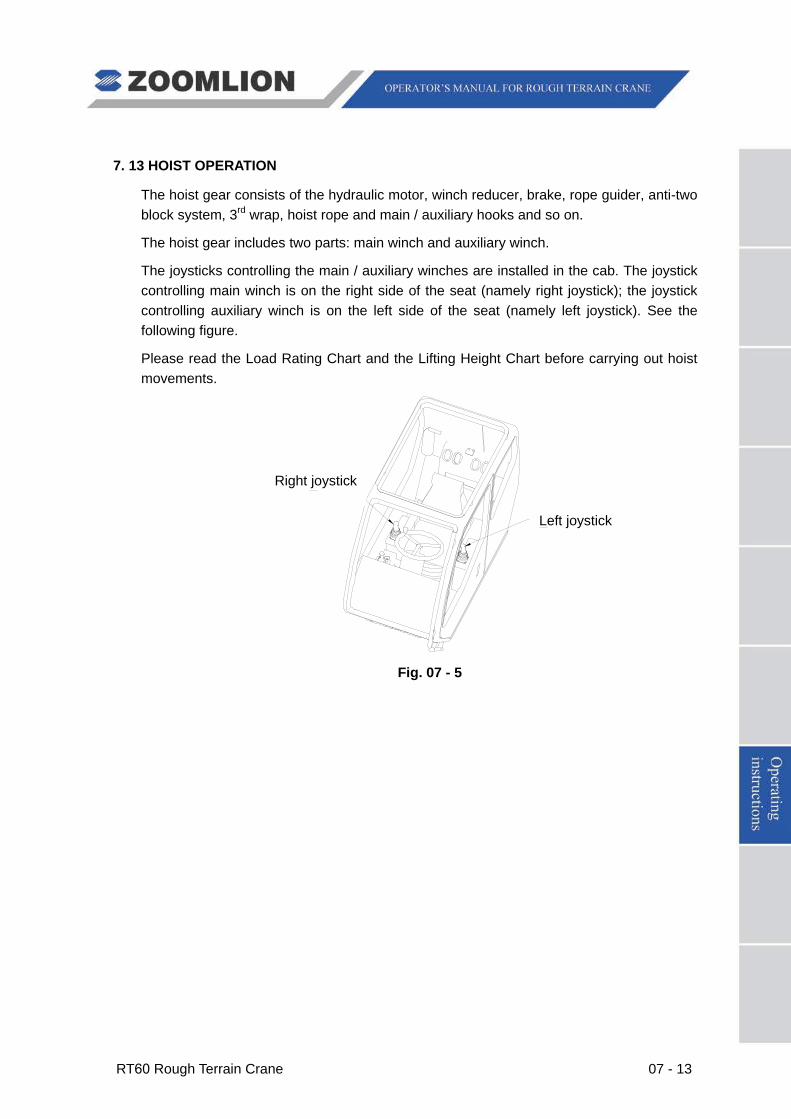
RT60 Rough Terrain Crane 07 - 13
7. 13 HOIST OPERATION
The hoist gear consists of the hydraulic motor, winch reducer, brake, rope guider, anti-two block system, 3rd
The hoist gear includes two parts: main winch and auxiliary winch.
wrap, hoist rope and main / auxiliary hooks and so on.
The joysticks controlling the main / auxiliary winches are installed in the cab. The joystick controlling main winch is on the right side of the seat (namely right joystick); the joystick controlling auxiliary winch is on the left side of the seat (namely left joystick). See the following figure.
Please read the Load Rating Chart and the Lifting Height Chart before carrying out hoist movements.
Fig. 07 - 5
Right joystick
Left joystick
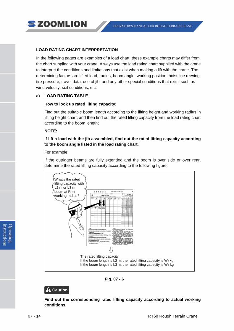
07 - 14 RT60 Rough Terrain Crane
LOAD RATING CHART INTERPRETATION
In the following pages are examples of a load chart, these example charts may differ from the chart supplied with your crane. Always use the load rating chart supplied with the crane to interpret the conditions and limitations that exist when making a lift with the crane. The determining factors are lifted load, radius, boom angle, working position, hoist line reeving, tire pressure, travel data, use of jib, and any other special conditions that exits, such as wind velocity, soil conditions, etc.
a) LOAD RATING TABLE
How to look up rated lifting capacity:
Find out the suitable boom length according to the lifting height and working radius in lifting height chart, and then find out the rated lifting capacity from the load rating chart according to the boom length;
NOTE:
If lift a load with the jib assembled, find out the rated lifting capacity according to the boom angle listed in the load rating chart.
For example:
If the outrigger beams are fully extended and the boom is over side or over rear, determine the rated lifting capacity according to the following figure:
Fig. 07 - 6
Find out the corresponding rated lifting capacity according to actual working conditions.
Caution
The rated lifting capacity: If the boom length is L2 m, the rated lifting capacity is W2 kg. If the boom length is L3 m, the rated lifting capacity is W3 kg.
What’s the rated lifting capacity with L2 m or L3 m boom at R m working radius?
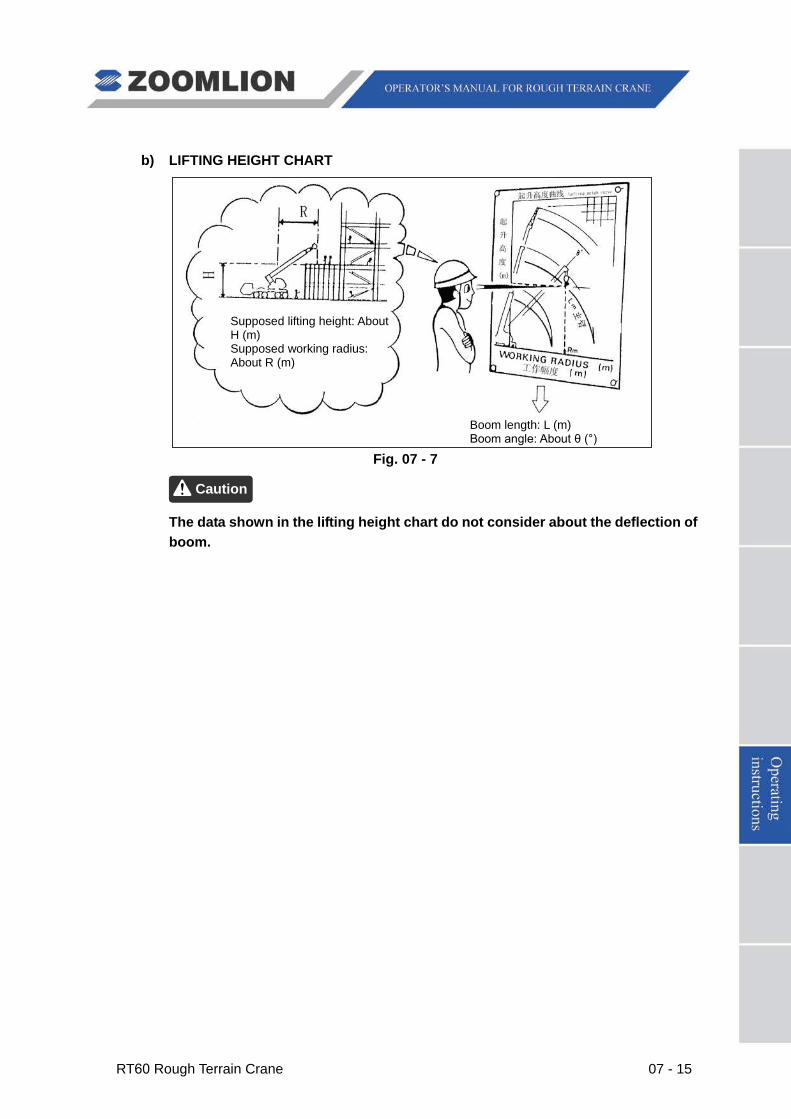
RT60 Rough Terrain Crane 07 - 15
b) LIFTING HEIGHT CHART
Fig. 07 - 7
The data shown in the lifting height chart do not consider about the deflection of boom.
Caution
Boom length: L (m) Boom angle: About θ (°)
Supposed lifting height: About H (m) Supposed working radius: About R (m)
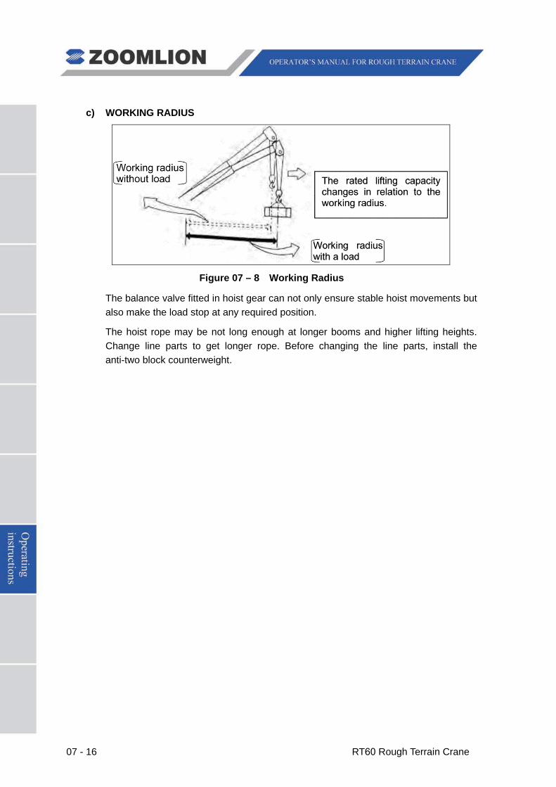
07 - 16 RT60 Rough Terrain Crane
c) WORKING RADIUS
Figure 07 – 8 Working Radius
The balance valve fitted in hoist gear can not only ensure stable hoist movements but also make the load stop at any required position.
The hoist rope may be not long enough at longer booms and higher lifting heights. Change line parts to get longer rope. Before changing the line parts, install the anti-two block counterweight.
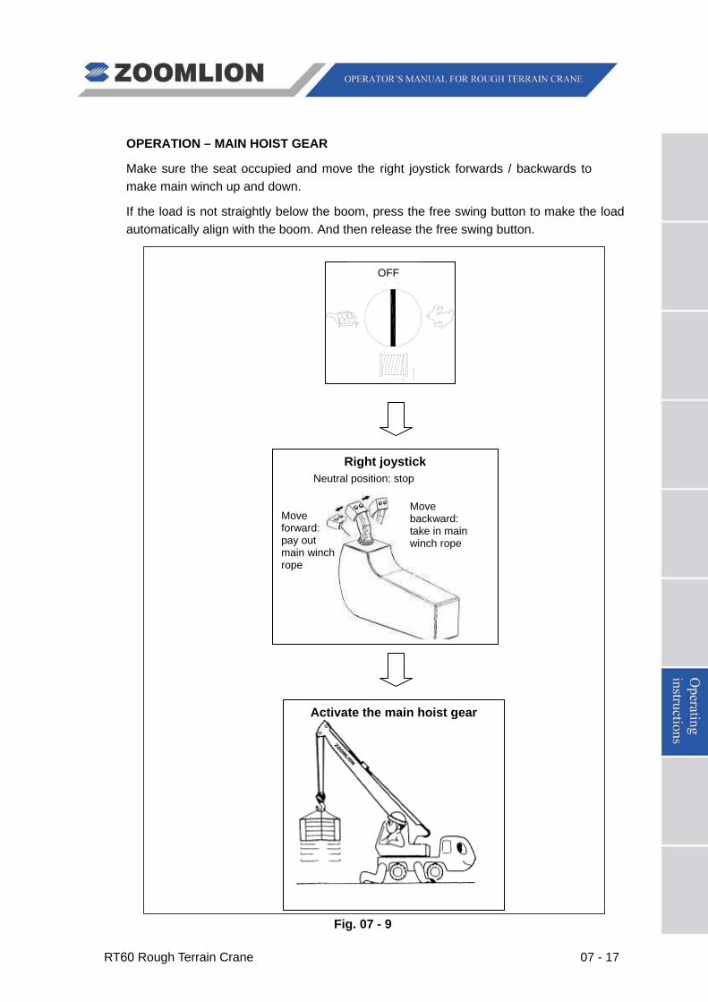
RT60 Rough Terrain Crane 07 - 17
OPERATION – MAIN HOIST GEAR
Make sure the seat occupied and move the right joystick forwards / backwards to make main winch up and down.
If the load is not straightly below the boom, press the free swing button to make the load automatically align with the boom. And then release the free swing button.
Fig. 07 - 9
Right joystick
Activate the main hoist gear
OFF
Move forward: pay out main winch rope
Move backward: take in main winch rope
Neutral position: stop
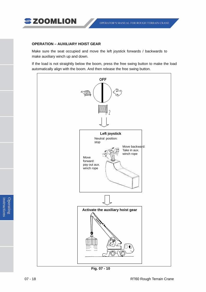
07 - 18 RT60 Rough Terrain Crane
OPERATION – AUXILIARY HOIST GEAR
Make sure the seat occupied and move the left joystick forwards / backwards to make auxiliary winch up and down.
If the load is not straightly below the boom, press the free swing button to make the load automatically align with the boom. And then release the free swing button.
Fig. 07 - 10
Left joystick
Move forward: pay out aux. winch rope
Move backward: Take in aux. winch rope
Neutral position: stop
Activate the auxiliary hoist gear
OFF
RT60 Rough Terrain Crane 07 - 19
After the hoist movements finished, move the joystick to the neutral position slowly to stop the movements.
The hoist speed increases as the HIGH / LOW SPEED CHANGEOVER SWITCH FOR MAIN / AUXILIARY WINCH on the dash is turned to stage “High” and the joysticks is moved further forward or backward. Hoist speed also varies with the engine speed.
Do not change the speed abruptly to ensure stable movements.
If the hook block contacts the anti-two block weight, acoustic / visual warning will be sent out and the movements “Winch up”, “Boom extend” and “Luff boom down” will be switched off; if there are only 3 wraps of rope remained on the winch, the movement “Winch down” will be switched off; if the actual load exceeds the rated one, acoustic / visual warning will be sent out and the movements “Winch up”, “Boom extend” and “Luff boom down” will be switched off.
If necessary, this switch-off can be bypassed by the bypass key switch in cab. Only carry out bypassed movements with maximum care and minimum speed during commissioning and maintenance.
It is forbidden to use the bypass key switch during normal crane operation.
(1) Select proper line parts in accordance with the actual boom length and load weights to be picked. If the hook rotates due to twisted rope, lay down the load on the ground. Don’t lift the load until the rope is totally untangled;
(2) Be sure to provide for no less than three full wraps of wire rope remaining on the winch drum under any working conditions;
(3) Lift the load vertically and it is forbidden to lift the load diagonally. Do not laterally drag the load which is still on the ground;
(4) Lift the load away from the ground a little and stop for a while. Continue lifting after ensure that there is no hazard around. Do not attempt to use more than one function, such as “Luff boom up” and “Boom extend”, to lift the load away from the ground;
(5) Do not change between “Winch up” and “Winch down” jerkily. If you want to interchange the two movements, return the joystick to neutral position and ensure the winding drum has stopped rotating. Otherwise, the machine will be damaged;
(6) The slings must be of enough strength. The lifting capacity includes the mass of hook block and slings besides that of the load;
(7) The crane cannot be used to lift person.
Caution
Warning
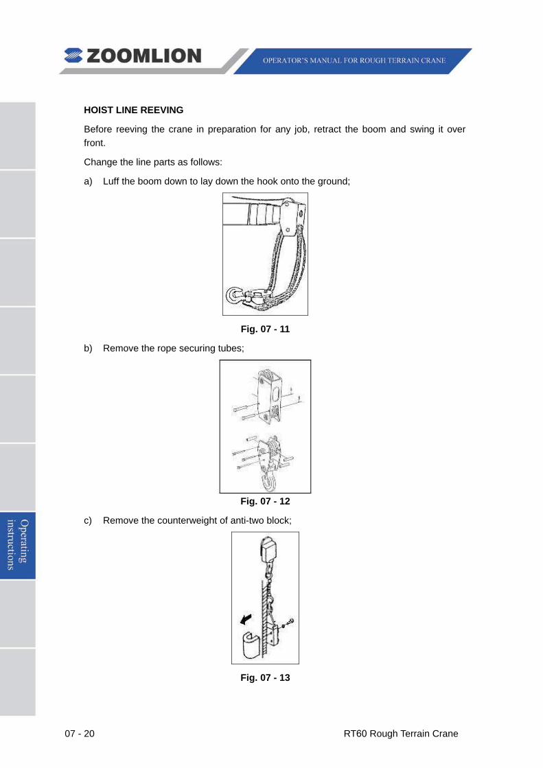
07 - 20 RT60 Rough Terrain Crane
HOIST LINE REEVING
Before reeving the crane in preparation for any job, retract the boom and swing it over front.
Change the line parts as follows:
a) Luff the boom down to lay down the hook onto the ground;
Fig. 07 - 11
b) Remove the rope securing tubes;
Fig. 07 - 12
c) Remove the counterweight of anti-two block;
Fig. 07 - 13
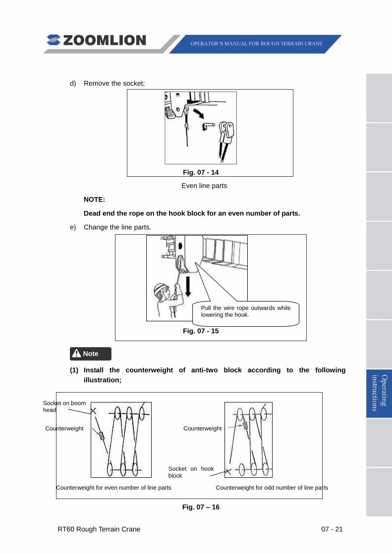
RT60 Rough Terrain Crane 07 - 21
d) Remove the socket;
Fig. 07 - 14
Even line parts
NOTE:
Dead end the rope on the hook block for an even number of parts.
e) Change the line parts.
Fig. 07 - 15
(1) Install the counterweight of anti-two block according to the following illustration;
Counterweight for even number of line parts Counterweight for odd number of line parts
Fig. 07 – 16
Note
Counterweight Counterweight
Socket on boom head
Pull the wire rope outwards while lowering the hook.
Socket on hook block
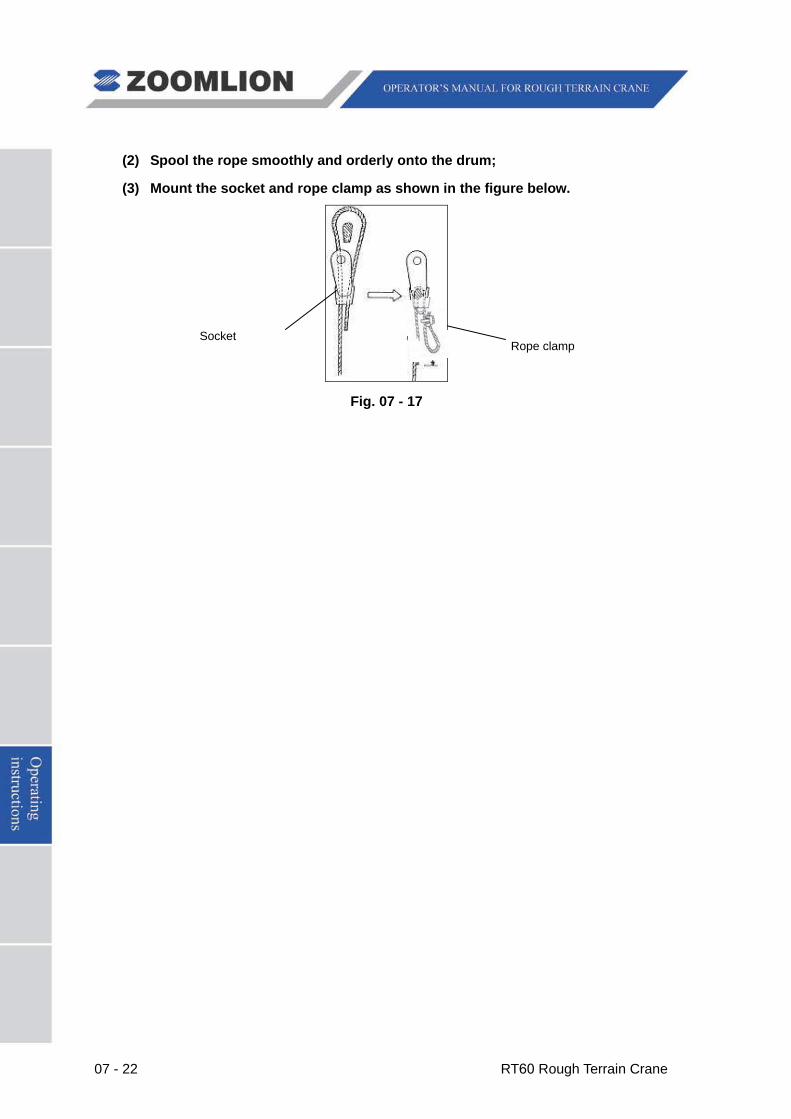
07 - 22 RT60 Rough Terrain Crane
(2) Spool the rope smoothly and orderly onto the drum;
(3) Mount the socket and rope clamp as shown in the figure below.
Fig. 07 - 17
SocketRope clamp
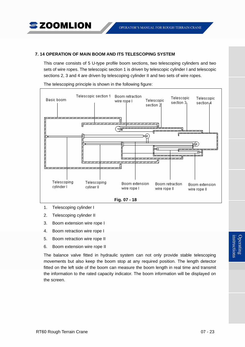
RT60 Rough Terrain Crane 07 - 23
7. 14 OPERATION OF MAIN BOOM AND ITS TELESCOPING SYSTEM
This crane consists of 5 U-type profile boom sections, two telescoping cylinders and two
sets of wire ropes. The telescopic section 1 is driven by telescopic cylinder I and telescopic
sections 2, 3 and 4 are driven by telescoping cylinder II and two sets of wire ropes.
The telescoping principle is shown in the following figure:
Fig. 07 - 18
1. Telescoping cylinder I
2. Telescoping cylinder II
3. Boom extension wire rope I
4. Boom retraction wire rope I
5. Boom retraction wire rope II
6. Boom extension wire rope II
The balance valve fitted in hydraulic system can not only provide stable telescoping
movements but also keep the boom stop at any required position. The length detector
fitted on the left side of the boom can measure the boom length in real time and transmit
the information to the rated capacity indicator. The boom information will be displayed on
the screen.
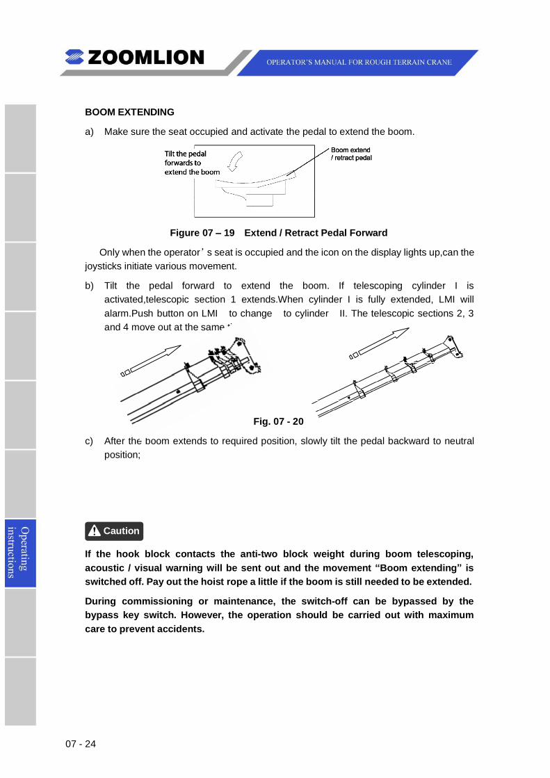
07 - 24
BOOM EXTENDING
a) Make sure the seat occupied and activate the pedal to extend the boom.
Figure 07 – 19 Extend / Retract Pedal Forward
Only when the operator’s seat is occupied and the icon on the display lights up,can thejoysticks initiate various movement.
b) Tilt the pedal forward to extend the boom. If telescoping cylinder I isactivated,telescopic section 1 extends.When cylinder I is fully extended, LMI willalarm.Push button on LMI to change to cylinder II. The telescopic sections 2, 3and 4 move out at the same time;
Fig. 07 - 20
c) After the boom extends to required position, slowly tilt the pedal backward to neutralposition;
Caution
If the hook block contacts the anti-two block weight during boom telescoping,acoustic / visual warning will be sent out and the movement “Boom extending” isswitched off. Pay out the hoist rope a little if the boom is still needed to be extended.
During commissioning or maintenance, the switch-off can be bypassed by thebypass key switch. However, the operation should be carried out with maximumcare to prevent accidents.
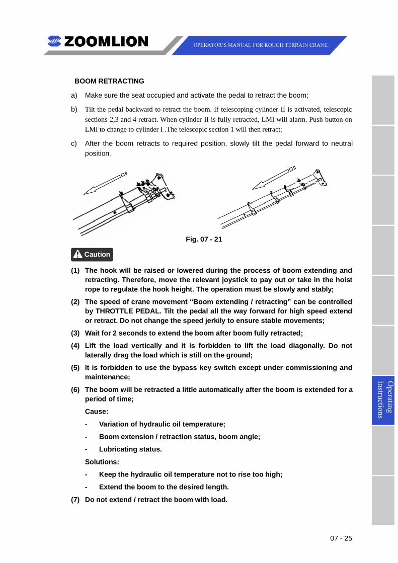
07 - 25
BOOM RETRACTING
a) Make sure the seat occupied and activate the pedal to retract the boom;
b) Tilt the pedal backward to retract the boom. If telescoping cylinder II is activated, telescopicsections 2,3 and 4 retract. When cylinder II is fully retracted, LMI will alarm. Push button onLMI to change to cylinder I .The telescopic section 1 will then retract;
c) After the boom retracts to required position, slowly tilt the pedal forward to neutralposition.
Fig. 07 - 21
Caution
(1) The hook will be raised or lowered during the process of boom extending andretracting. Therefore, move the relevant joystick to pay out or take in the hoistrope to regulate the hook height. The operation must be slowly and stably;
(2) The speed of crane movement “Boom extending / retracting” can be controlledby THROTTLE PEDAL. Tilt the pedal all the way forward for high speed extendor retract. Do not change the speed jerkily to ensure stable movements;
(3) Wait for 2 seconds to extend the boom after boom fully retracted;
(4) Lift the load vertically and it is forbidden to lift the load diagonally. Do notlaterally drag the load which is still on the ground;
(5) It is forbidden to use the bypass key switch except under commissioning andmaintenance;
(6) The boom will be retracted a little automatically after the boom is extended for aperiod of time;
Cause:
- Variation of hydraulic oil temperature;
- Boom extension / retraction status, boom angle;
- Lubricating status.
Solutions:
- Keep the hydraulic oil temperature not to rise too high;
- Extend the boom to the desired length.
(7) Do not extend / retract the boom with load.
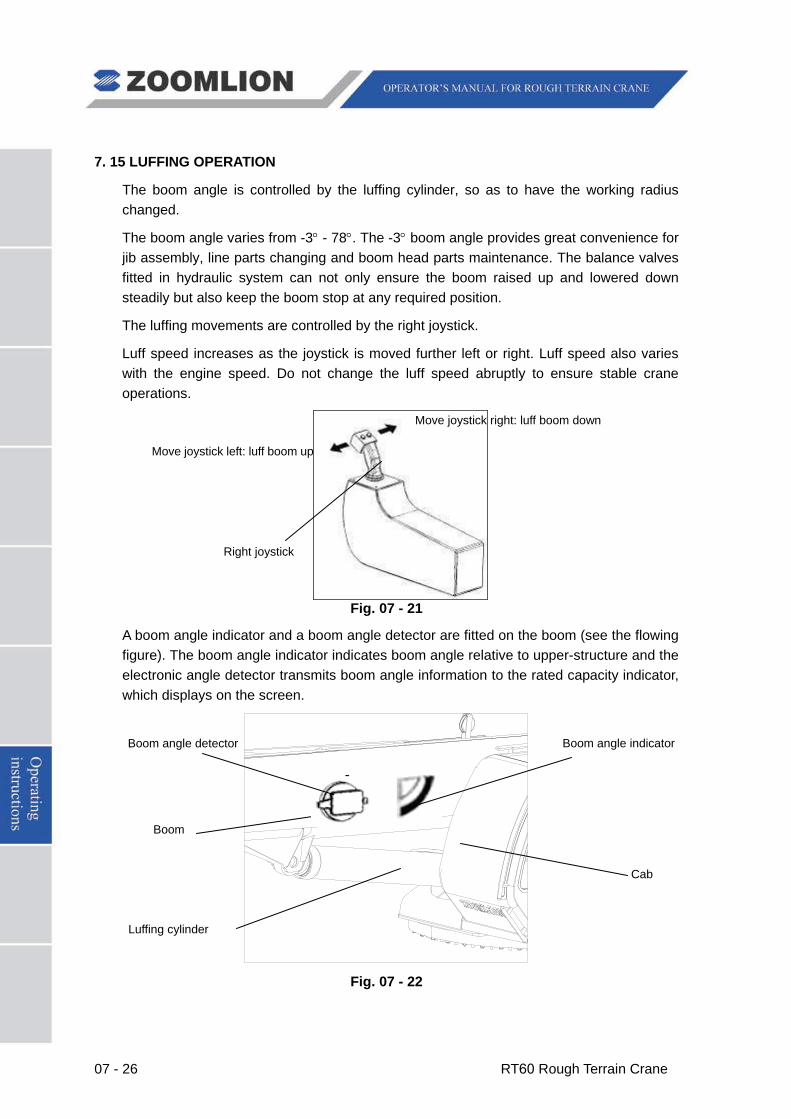
07 - 26 RT60 Rough Terrain Crane
7. 15 LUFFING OPERATION The boom angle is controlled by the luffing cylinder, so as to have the working radius changed.
The boom angle varies from -3° - 78°. The -3° boom angle provides great convenience for jib assembly, line parts changing and boom head parts maintenance. The balance valves fitted in hydraulic system can not only ensure the boom raised up and lowered down steadily but also keep the boom stop at any required position.
The luffing movements are controlled by the right joystick.
Luff speed increases as the joystick is moved further left or right. Luff speed also varies with the engine speed. Do not change the luff speed abruptly to ensure stable crane operations.
Fig. 07 - 21
A boom angle indicator and a boom angle detector are fitted on the boom (see the flowing figure). The boom angle indicator indicates boom angle relative to upper-structure and the electronic angle detector transmits boom angle information to the rated capacity indicator, which displays on the screen.
Fig. 07 - 22
Move joystick left: luff boom up
Move joystick right: luff boom down
Right joystick
Cab
Boom
Luffing cylinder
Boom angle detector Boom angle indicator
RT60 Rough Terrain Crane 07 - 27
(1) Always operate and release the controls slowly to minimize dynamic effects of the load;
(2) The working radius will increase during lifting a load with boom lowered down. So as to make the crane topple over due to overloading. Operate the crane strictly in accordance with the Load Rating Chart.
Warning
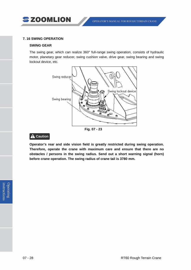
07 - 28 RT60 Rough Terrain Crane
7. 16 SWING OPERATION
SWING GEAR
The swing gear, which can realize 360° full-range swing operation, consists of hydraulic motor, planetary gear reducer, swing cushion valve, drive gear, swing bearing and swing lockout device, etc.
Fig. 07 - 23
Operator’s rear and side vision field is greatly restricted during swing operation. Therefore, operate the crane with maximum care and ensure that there are no obstacles / persons in the swing radius. Send out a short warning signal (horn) before crane operation. The swing radius of crane tail is 3780 mm.
Caution
RT60 Rough Terrain Crane 07 - 29
SWING OPERATION DURING LIFTING
Disengage the swing lock.
(SWING UNLOCK INDICATOR illuminates) Fig. 07 - 24
Swing speed increases as the joystick is moved further left or right. Swing speed also varies with the engine speed. Do not change the swing speed abruptly to ensure stable crane operations.
Fig. 07 - 25
Move the joystick left: swing to the left
Neutral position: stop
Move the joystick right: swing to the right
Left joystick
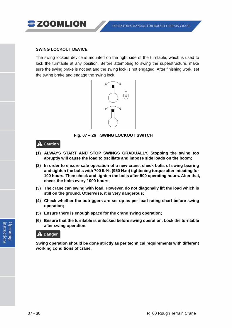
07 - 30 RT60 Rough Terrain Crane
SWING LOCKOUT DEVICE
The swing lockout device is mounted on the right side of the turntable, which is used to lock the turntable at any position. Before attempting to swing the superstructure, make sure the swing brake is not set and the swing lock is not engaged. After finishing work, set the swing brake and engage the swing lock.
Fig. 07 – 26 SWING LOCKOUT SWITCH
(1) ALWAYS START AND STOP SWINGS GRADUALLY. Stopping the swing too abruptly will cause the load to oscillate and impose side loads on the boom;
(2) In order to ensure safe operation of a new crane, check bolts of swing bearing and tighten the bolts with 700 lbf·ft (950 N.m) tightening torque after initiating for 100 hours. Then check and tighten the bolts after 500 operating hours. After that, check the bolts every 1000 hours;
(3) The crane can swing with load. However, do not diagonally lift the load which is still on the ground. Otherwise, it is very dangerous;
(4) Check whether the outriggers are set up as per load rating chart before swing operation;
(5) Ensure there is enough space for the crane swing operation;
(6) Ensure that the turntable is unlocked before swing operation. Lock the turntable after swing operation.
Swing operation should be done strictly as per technical requirements with different working conditions of crane.
Danger
Caution
RT60 Rough Terrain Crane 07 - 31
7. 17 SIMULTANEOUS CRANE MOVEMENTS
The simultaneous crane movements, which can greatly improve the working efficiency, refer to that the crane can use more than one function at a time.
Before initiate crane simultaneous movements, you should:
a) Not attempt to move the joysticks to their limit positions.
b) Depress throttle pedal.
c) Take maximum care to avoid accident.
The crane offers 9 simultaneous crane movements.
Simultaneous crane movements can only be carried out without load or when the load has been lifted away from the ground. DO NOT EXTEND / RETRACT THE BOOM WITH LOAD.
Warning
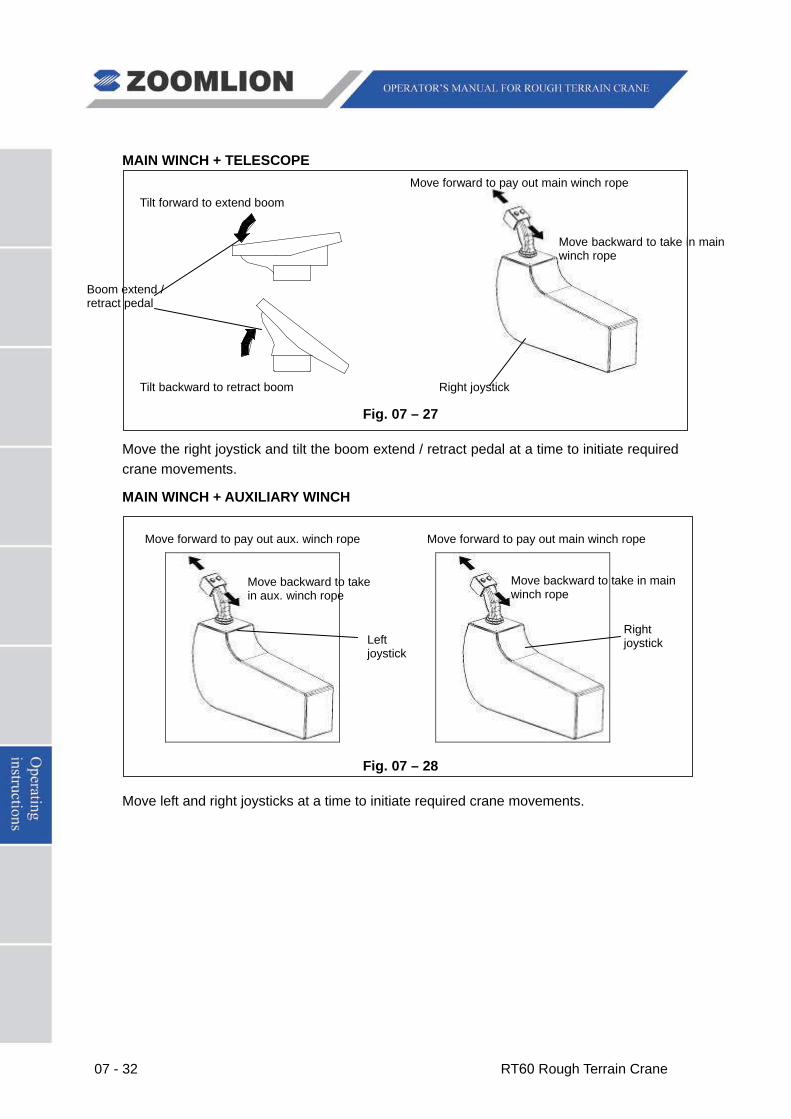
07 - 32 RT60 Rough Terrain Crane
MAIN WINCH + TELESCOPE
Fig. 07 – 27
Move the right joystick and tilt the boom extend / retract pedal at a time to initiate required crane movements.
MAIN WINCH + AUXILIARY WINCH
Fig. 07 – 28
Move left and right joysticks at a time to initiate required crane movements.
Tilt forward to extend boom
Tilt backward to retract boom
Move forward to pay out main winch rope
Move backward to take in main winch rope
Boom extend / retract pedal
Right joystick
Move forward to pay out aux. winch rope
Move backward to take in aux. winch rope
Left joystick
Move forward to pay out main winch rope
Move backward to take in main winch rope
Right joystick
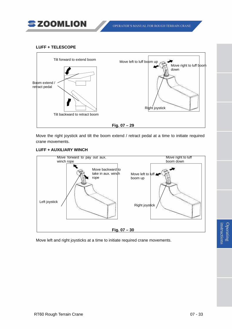
RT60 Rough Terrain Crane 07 - 33
LUFF + TELESCOPE
Fig. 07 – 3 Fig. 07 – 29
Fig. 07 – 29
Move the right joystick and tilt the boom extend / retract pedal at a time to initiate required crane movements.
LUFF + AUXILIARY WINCH
按图示方向同时操作左、右手柄,即可使起重机主臂变幅和副卷扬同时动作。
Fig. 07 – 32
Fig. 07 – 30
Move left and right joysticks at a time to initiate required crane movements.
Move right to luff boom down
Move left to luff boom up
Right joystick
Move forward to pay out aux. winch rope
Move backward to take in aux. winch rope
Move right to luff boom down
Move left to luff boom up
Left joystick Right joystick
Tilt forward to extend boom
Tilt backward to retract boom
Boom extend / retract pedal
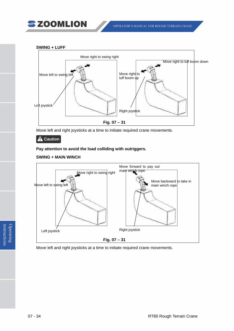
07 - 34 RT60 Rough Terrain Crane
SWING + LUFF
Fig. 07 – 31
Move left and right joysticks at a time to initiate required crane movements.
Pay attention to avoid the load colliding with outriggers.
SWING + MAIN WINCH
Fig. 07 – 31
Move left and right joysticks at a time to initiate required crane movements.
Caution
Move right to swing right
Move left to swing left
Move right to luff boom down
Move right to luff boom up
Left joystick Right joystick
Move right to swing right
Move left to swing left
Move forward to pay out main winch rope
Move backward to take in main winch rope
Left joystick Right joystick
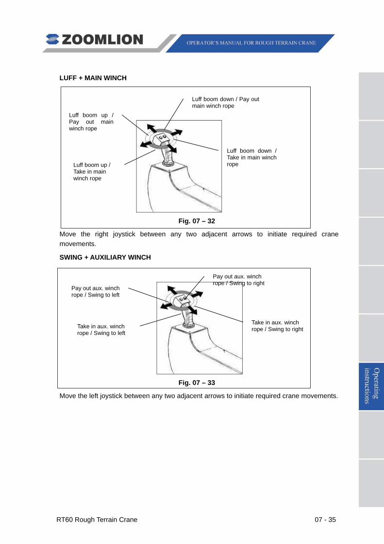
RT60 Rough Terrain Crane 07 - 35
LUFF + MAIN WINCH
Fig. 07 – 32
Move the right joystick between any two adjacent arrows to initiate required crane movements.
SWING + AUXILIARY WINCH
Fig. 07 – 33
Move the left joystick between any two adjacent arrows to initiate required crane movements.
Luff boom down / Take in main winch rope
Luff boom down / Pay out main winch rope
Luff boom up / Pay out main winch rope
Luff boom up / Take in main winch rope
Take in aux. winch rope / Swing to right
Pay out aux. winch rope / Swing to right
Pay out aux. winch rope / Swing to left
Take in aux. winch rope / Swing to left
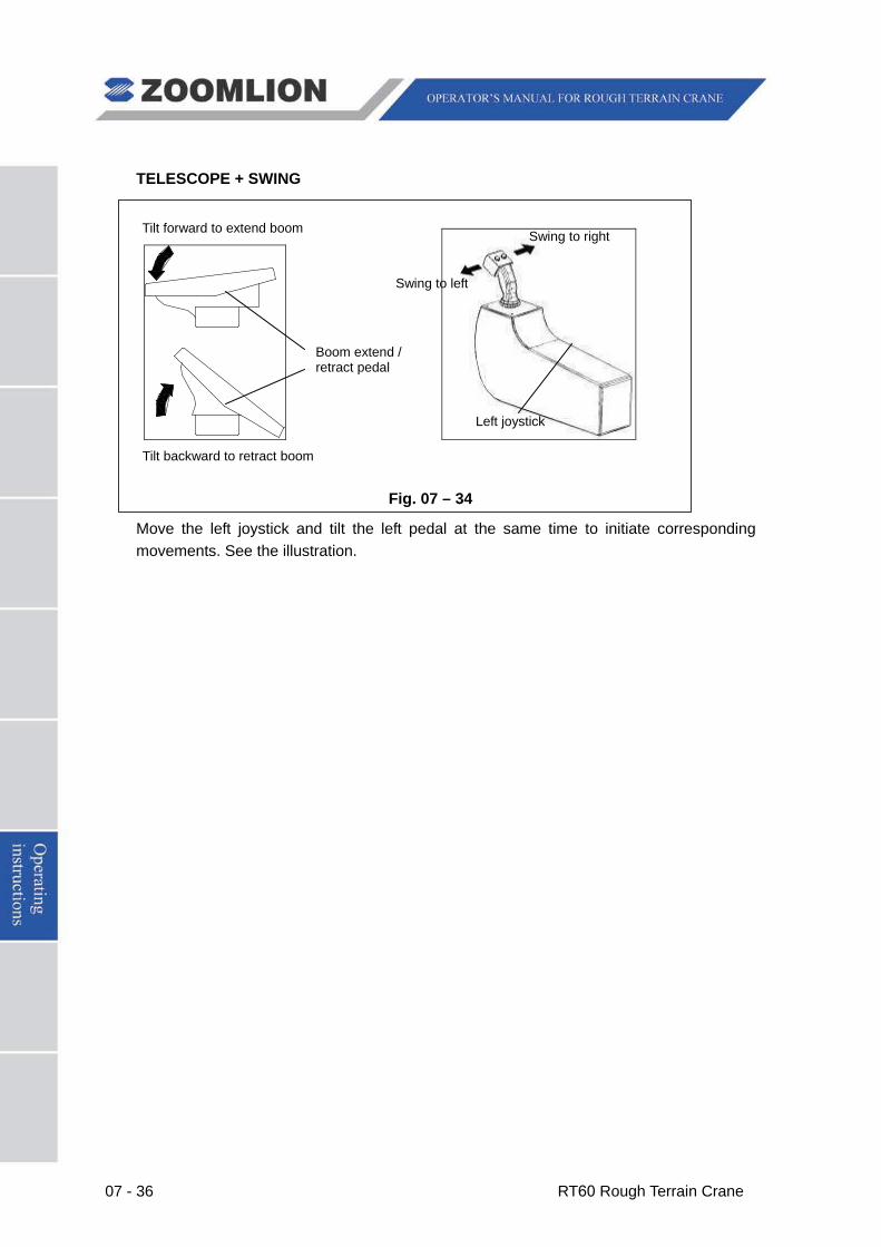
07 - 36 RT60 Rough Terrain Crane
TELESCOPE + SWING
Fig. 07 – 34
Move the left joystick and tilt the left pedal at the same time to initiate corresponding movements. See the illustration.
Tilt forward to extend boom
Tilt backward to retract boom
Boom extend / retract pedal
Swing to left
Swing to right
Left joystick
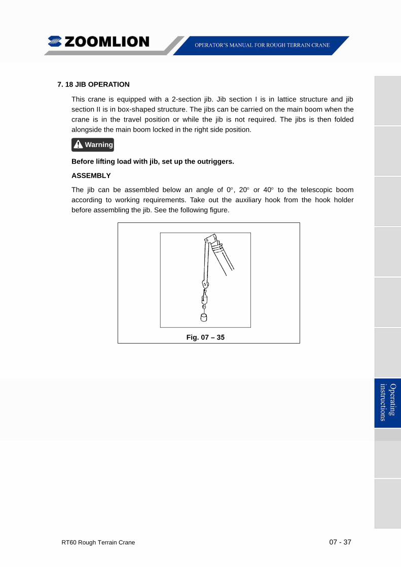
RT60 Rough Terrain Crane 07 - 37
7. 18 JIB OPERATION
This crane is equipped with a 2-section jib. Jib section I is in lattice structure and jib
section II is in box-shaped structure. The jibs can be carried on the main boom when the
crane is in the travel position or while the jib is not required. The jibs is then folded
alongside the main boom locked in the right side position.
Before lifting load with jib, set up the outriggers.
ASSEMBLY
The jib can be assembled below an angle of 0, 20 or 40 to the telescopic boom
according to working requirements. Take out the auxiliary hook from the hook holder
before assembling the jib. See the following figure.
Fig. 07 – 35
Warning
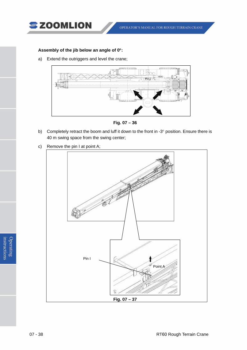
07 - 38 RT60 Rough Terrain Crane
Assembly of the jib below an angle of 0°:
a) Extend the outriggers and level the crane;
Fig. 07 – 36
b) Completely retract the boom and luff it down to the front in -3° position. Ensure there is 40 m swing space from the swing center;
c) Remove the pin I at point A;
Fig. 07 – 37
Pin I
Point A
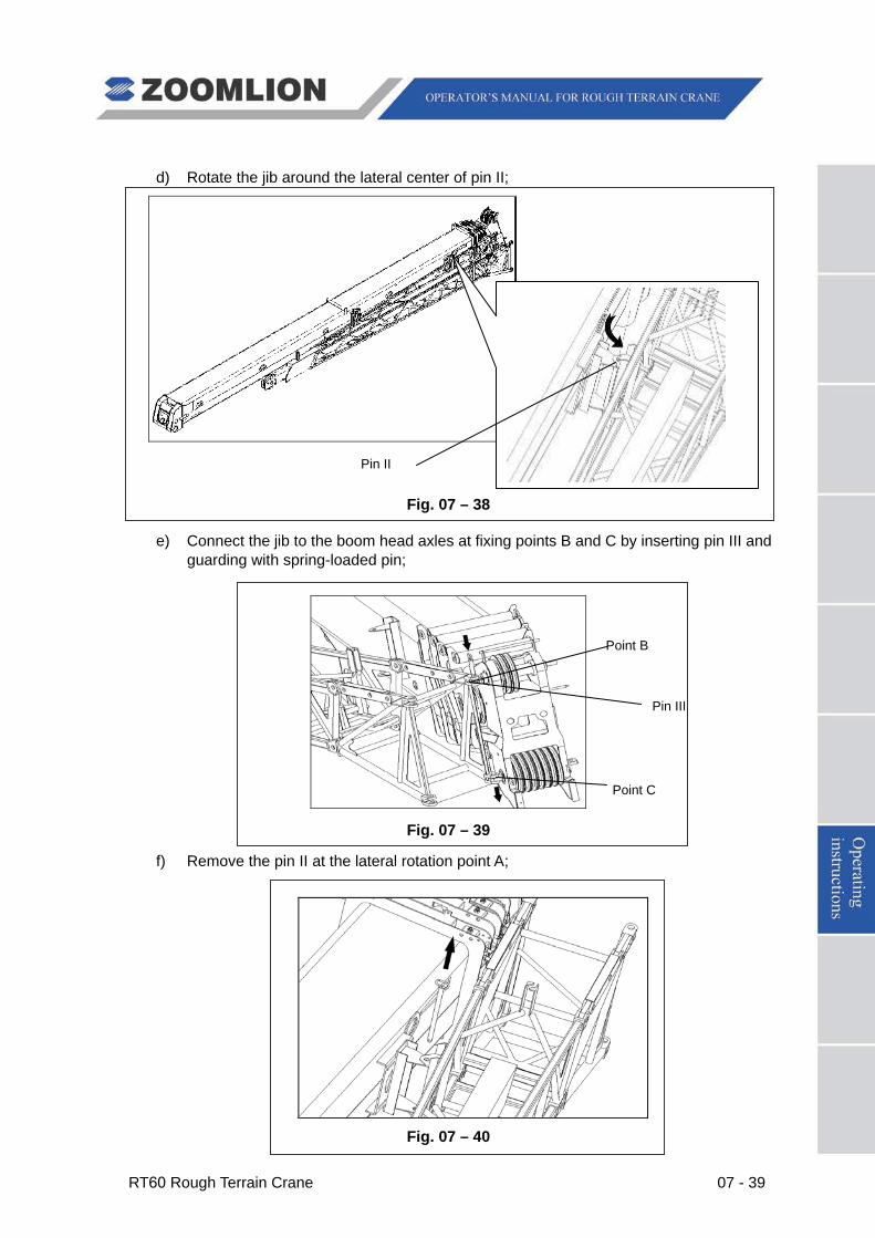
RT60 Rough Terrain Crane 07 - 39
d) Rotate the jib around the lateral center of pin II;
Fig. 07 – 38
e) Connect the jib to the boom head axles at fixing points B and C by inserting pin III and guarding with spring-loaded pin;
Fig. 07 – 39
f) Remove the pin II at the lateral rotation point A;
Fig. 07 – 40
Pin II
Pin III
Point B
Point C
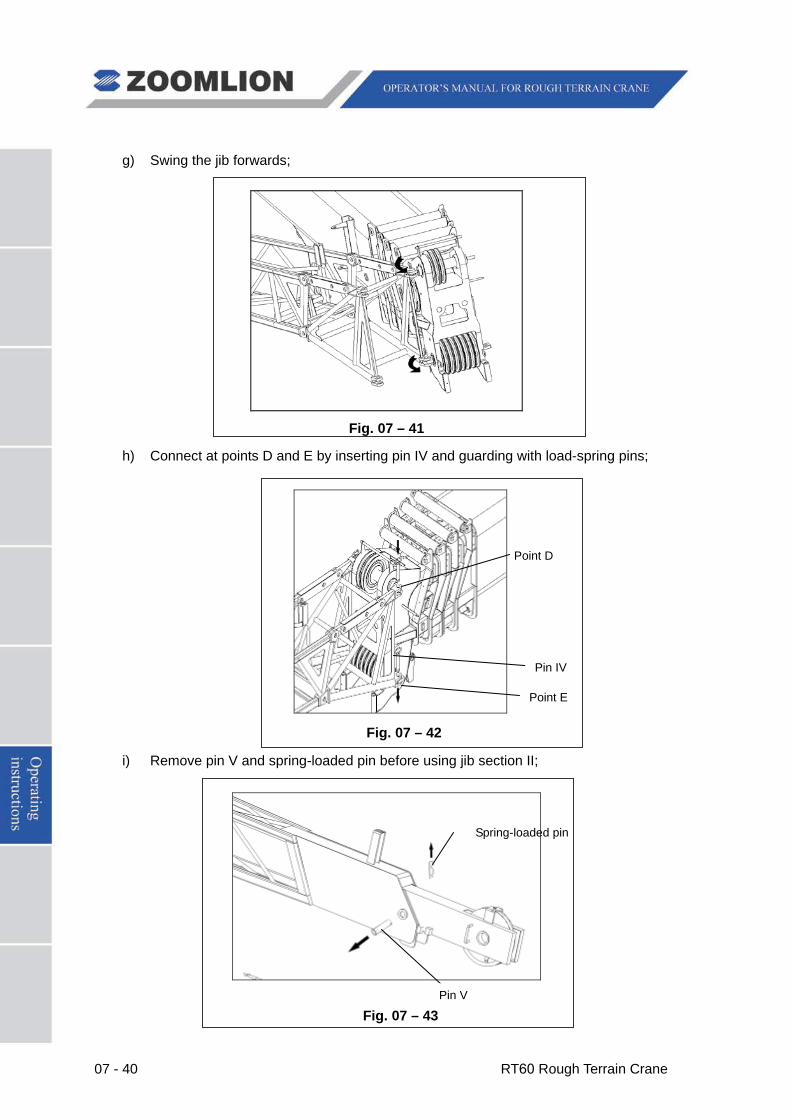
07 - 40 RT60 Rough Terrain Crane
g) Swing the jib forwards;
Fig. 07 – 41
h) Connect at points D and E by inserting pin IV and guarding with load-spring pins;
Fig. 07 – 42
i) Remove pin V and spring-loaded pin before using jib section II;
Fig. 07 – 43
Pin IV
Pin V
Spring-loaded pin
Point D
Point E
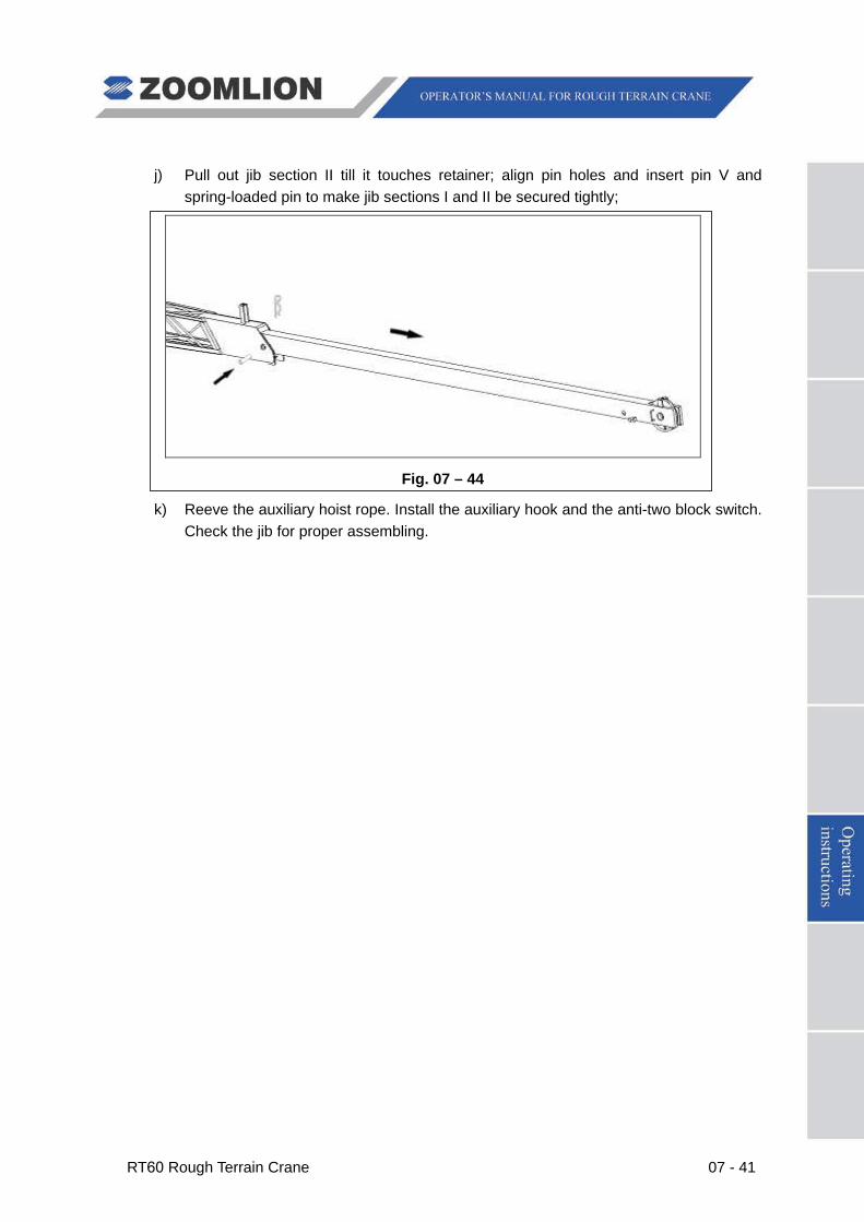
RT60 Rough Terrain Crane 07 - 41
j) Pull out jib section II till it touches retainer; align pin holes and insert pin V and spring-loaded pin to make jib sections I and II be secured tightly;
Fig. 07 – 44
k) Reeve the auxiliary hoist rope. Install the auxiliary hook and the anti-two block switch. Check the jib for proper assembling.
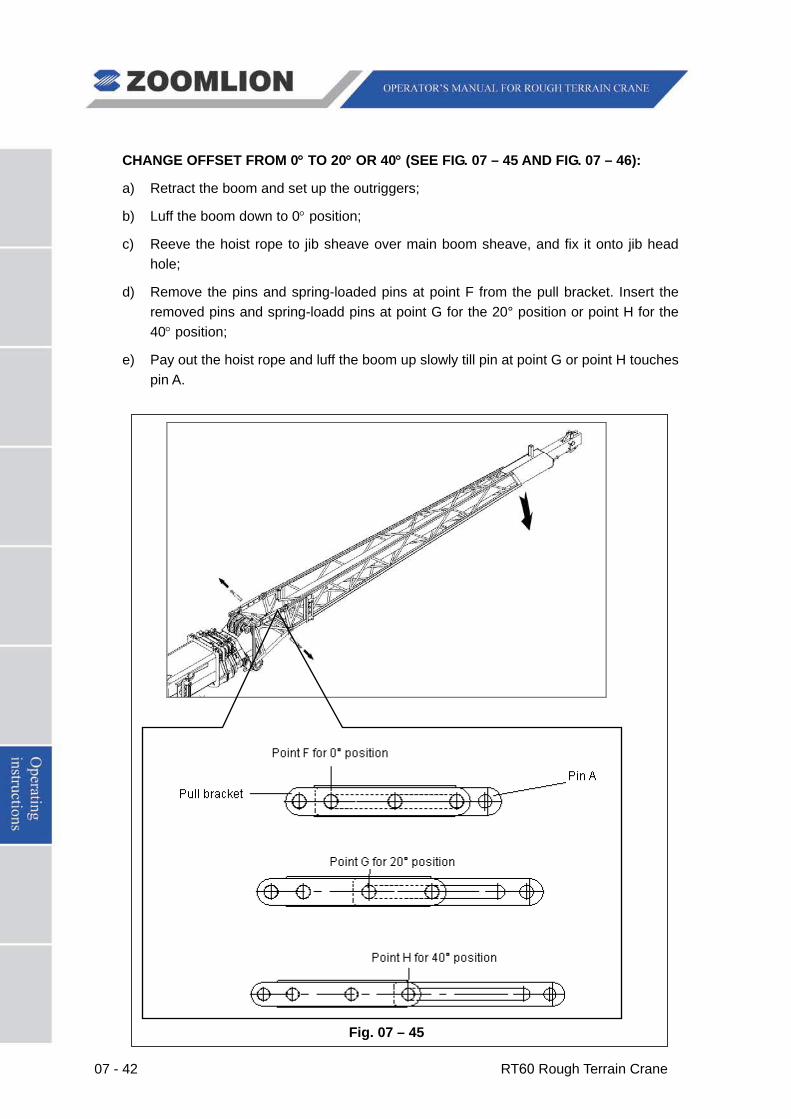
07 - 42 RT60 Rough Terrain Crane
CHANGE OFFSET FROM 0° TO 20° OR 40° (SEE FIG. 07 – 45 AND FIG. 07 – 46):
a) Retract the boom and set up the outriggers;
b) Luff the boom down to 0° position;
c) Reeve the hoist rope to jib sheave over main boom sheave, and fix it onto jib head hole;
d) Remove the pins and spring-loaded pins at point F from the pull bracket. Insert the removed pins and spring-loadd pins at point G for the 20° position or point H for the 40° position;
e) Pay out the hoist rope and luff the boom up slowly till pin at point G or point H touches pin A.
Fig. 07 – 45
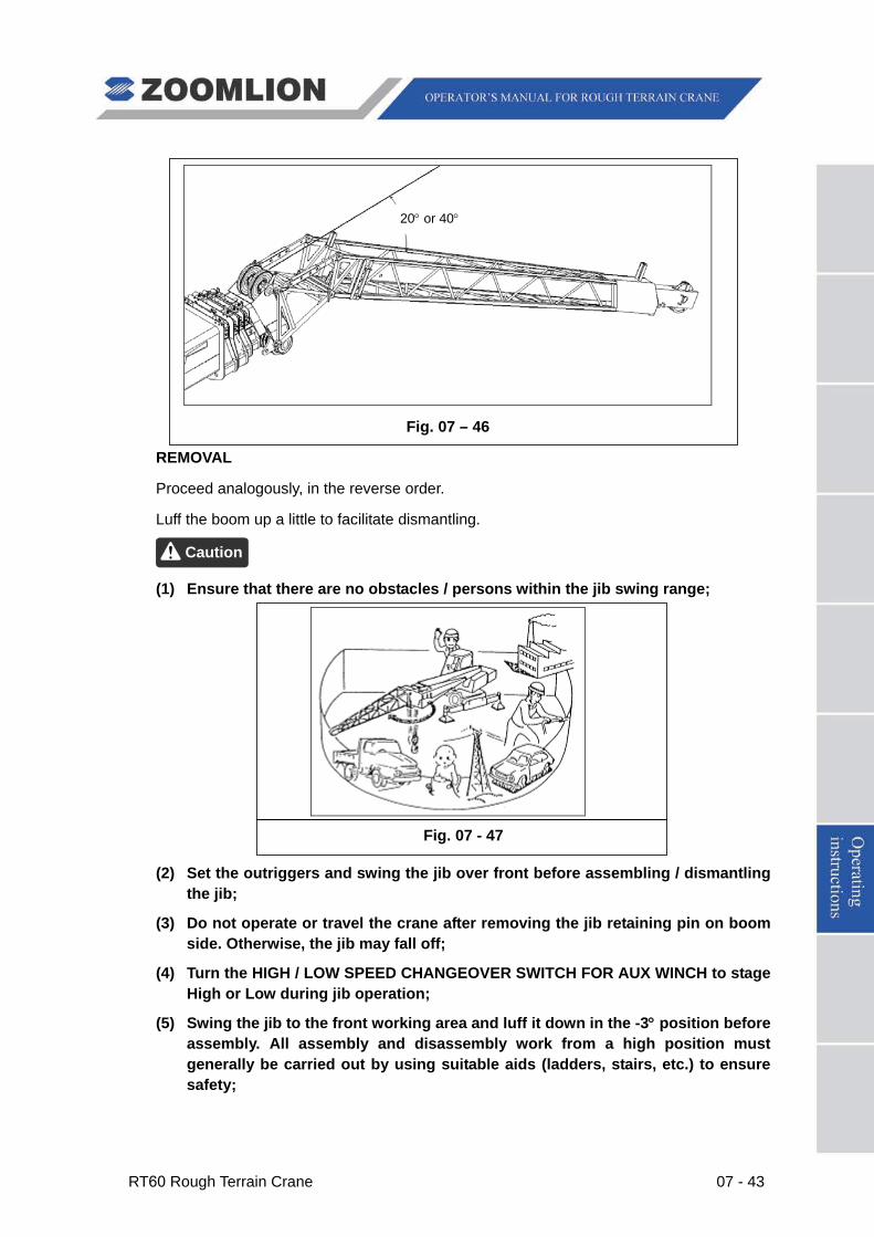
RT60 Rough Terrain Crane 07 - 43
Fig. 07 – 46
REMOVAL
Proceed analogously, in the reverse order.
Luff the boom up a little to facilitate dismantling.
(1) Ensure that there are no obstacles / persons within the jib swing range;
Fig. 07 - 47
(2) Set the outriggers and swing the jib over front before assembling / dismantling the jib;
(3) Do not operate or travel the crane after removing the jib retaining pin on boom side. Otherwise, the jib may fall off;
(4) Turn the HIGH / LOW SPEED CHANGEOVER SWITCH FOR AUX WINCH to stage High or Low during jib operation;
(5) Swing the jib to the front working area and luff it down in the -3° position before assembly. All assembly and disassembly work from a high position must generally be carried out by using suitable aids (ladders, stairs, etc.) to ensure safety;
Caution
20° or 40°
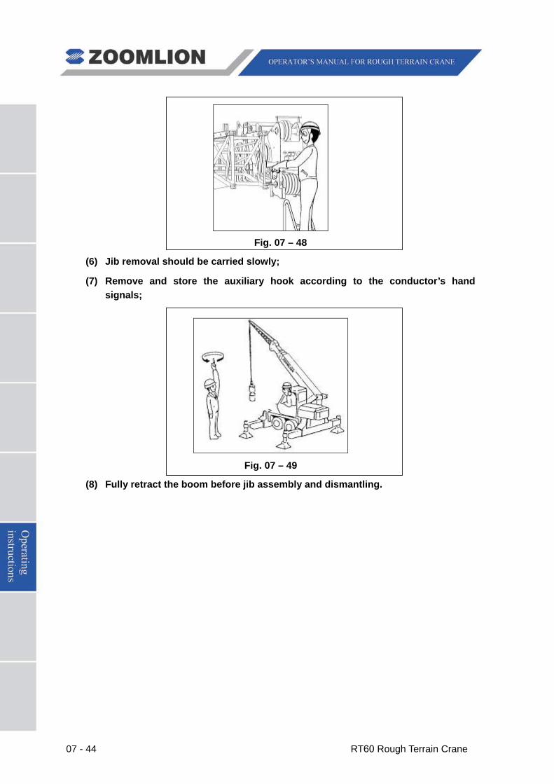
07 - 44 RT60 Rough Terrain Crane
Fig. 07 – 48
(6) Jib removal should be carried slowly;
(7) Remove and store the auxiliary hook according to the conductor’s hand signals;
Fig. 07 – 49
(8) Fully retract the boom before jib assembly and dismantling.
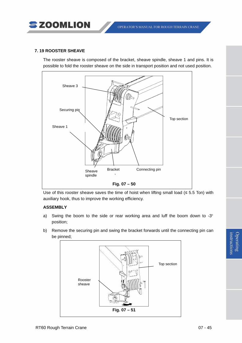
RT60 Rough Terrain Crane 07 - 45
7. 19 ROOSTER SHEAVE
The rooster sheave is composed of the bracket, sheave spindle, sheave 1 and pins. It is possible to fold the rooster sheave on the side in transport position and not used position.
Fig. 07 – 50
Use of this rooster sheave saves the time of hoist when lifting small load (≤ 5.5 Ton) with auxiliary hook, thus to improve the working efficiency.
ASSEMBLY
a) Swing the boom to the side or rear working area and luff the boom down to -3°position;
b) Remove the securing pin and swing the bracket forwards until the connecting pin can be pinned;
Fig. 07 – 51
Connecting pin Bracket Sheave spindle
Sheave 1
Securing pin
Top section
Top section
Rooster sheave
Sheave 3
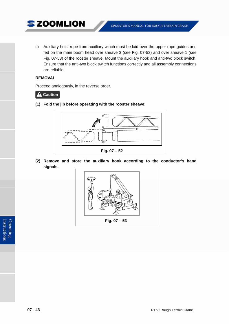
07 - 46 RT60 Rough Terrain Crane
c) Auxiliary hoist rope from auxiliary winch must be laid over the upper rope guides and
fed on the main boom head over sheave 3 (see Fig. 07-53) and over sheave 1 (see
Fig. 07-53) of the rooster sheave. Mount the auxiliary hook and anti-two block switch.
Ensure that the anti-two block switch functions correctly and all assembly connections
are reliable.
REMOVAL
Proceed analogously, in the reverse order.
(1) Fold the jib before operating with the rooster sheave;
Fig. 07 – 52
(2) Remove and store the auxiliary hook according to the conductor’s hand
signals.
Fig. 07 – 53
Caution
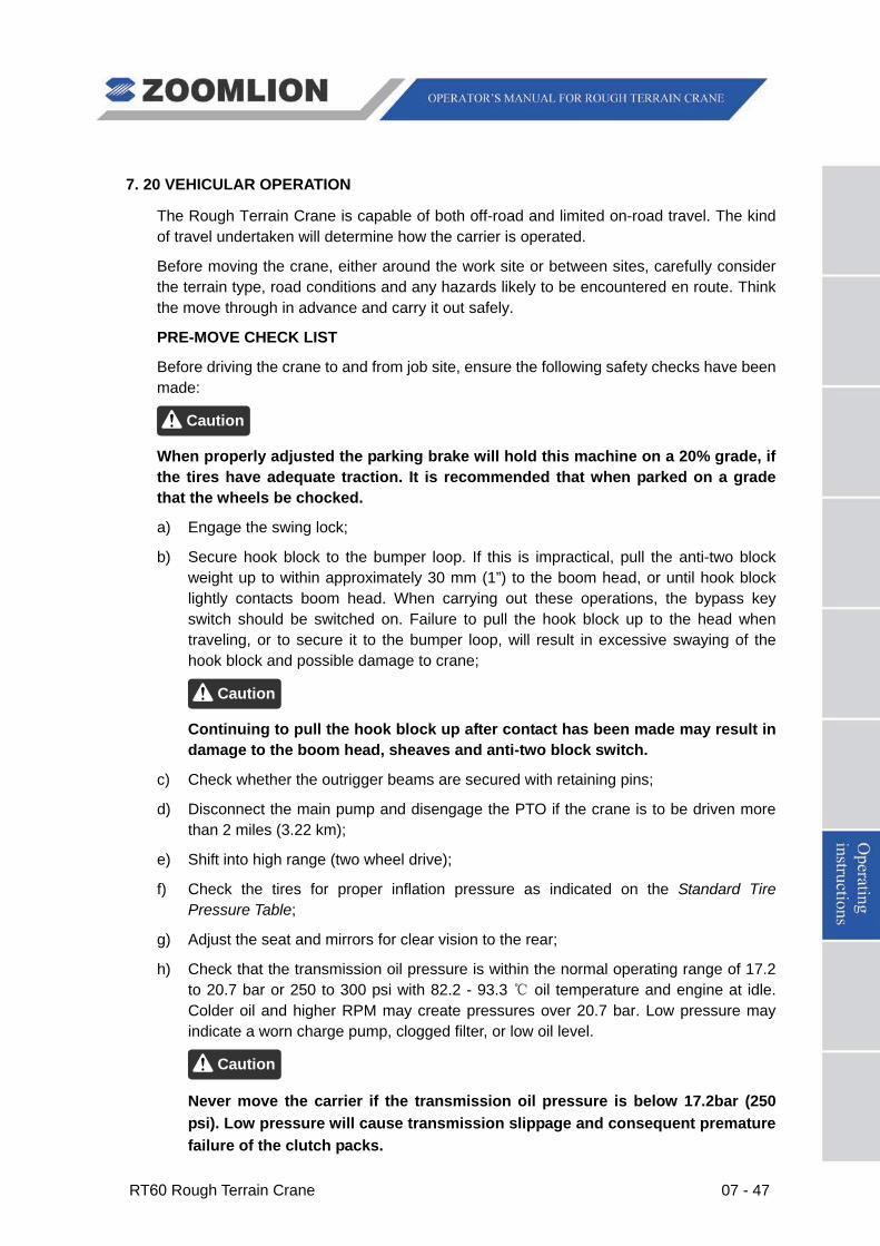
RT60 Rough Terrain Crane 07 - 47
7. 20 VEHICULAR OPERATION
The Rough Terrain Crane is capable of both off-road and limited on-road travel. The kind of travel undertaken will determine how the carrier is operated.
Before moving the crane, either around the work site or between sites, carefully consider the terrain type, road conditions and any hazards likely to be encountered en route. Think the move through in advance and carry it out safely.
PRE-MOVE CHECK LIST
Before driving the crane to and from job site, ensure the following safety checks have been made:
When properly adjusted the parking brake will hold this machine on a 20% grade, if the tires have adequate traction. It is recommended that when parked on a grade that the wheels be chocked.
a) Engage the swing lock;
b) Secure hook block to the bumper loop. If this is impractical, pull the anti-two block weight up to within approximately 30 mm (1”) to the boom head, or until hook block lightly contacts boom head. When carrying out these operations, the bypass key switch should be switched on. Failure to pull the hook block up to the head when traveling, or to secure it to the bumper loop, will result in excessive swaying of the hook block and possible damage to crane;
Continuing to pull the hook block up after contact has been made may result in damage to the boom head, sheaves and anti-two block switch.
c) Check whether the outrigger beams are secured with retaining pins;
d) Disconnect the main pump and disengage the PTO if the crane is to be driven more than 2 miles (3.22 km);
e) Shift into high range (two wheel drive);
f) Check the tires for proper inflation pressure as indicated on the Standard Tire Pressure Table;
g) Adjust the seat and mirrors for clear vision to the rear;
h) Check that the transmission oil pressure is within the normal operating range of 17.2 to 20.7 bar or 250 to 300 psi with 82.2 - 93.3 ℃ oil temperature and engine at idle. Colder oil and higher RPM may create pressures over 20.7 bar. Low pressure may indicate a worn charge pump, clogged filter, or low oil level.
Never move the carrier if the transmission oil pressure is below 17.2bar (250 psi). Low pressure will cause transmission slippage and consequent premature failure of the clutch packs.
Caution
Caution
Caution
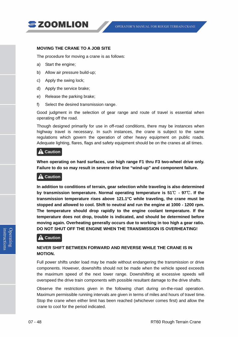
07 - 48 RT60 Rough Terrain Crane
MOVING THE CRANE TO A JOB SITE
The procedure for moving a crane is as follows:
a) Start the engine;
b) Allow air pressure build-up;
c) Apply the swing lock;
d) Apply the service brake;
e) Release the parking brake;
f) Select the desired transmission range.
Good judgment in the selection of gear range and route of travel is essential when operating off the road.
Though designed primarily for use in off-road conditions, there may be instances when highway travel is necessary. In such instances, the crane is subject to the same regulations which govern the operation of other heavy equipment on public roads. Adequate lighting, flares, flags and safety equipment should be on the cranes at all times.
When operating on hard surfaces, use high range F1 thru F3 two-wheel drive only. Failure to do so may result in severe drive line “wind-up” and component failure.
In addition to conditions of terrain, gear selection while traveling is also determined by transmission temperature. Normal operating temperature is 51℃ - 97℃. If the transmission temperature rises above 121.1°C while traveling, the crane must be stopped and allowed to cool. Shift to neutral and run the engine at 1000 - 1200 rpm. The temperature should drop rapidly to the engine coolant temperature. If the temperature does not drop, trouble is indicated, and should be determined before moving again. Overheating generally occurs due to working in too high a gear ratio. DO NOT SHUT OFF THE ENGINE WHEN THE TRANSMISSION IS OVERHEATING!
NEVER SHIFT BETWEEN FORWARD AND REVERSE WHILE THE CRANE IS IN MOTION.
Full power shifts under load may be made without endangering the transmission or drive components. However, downshifts should not be made when the vehicle speed exceeds the maximum speed of the next lower range. Downshifting at excessive speeds will overspeed the drive train components with possible resultant damage to the drive shafts.
Observe the restrictions given in the following chart during on-the-road operation. Maximum permissible running intervals are given in terms of miles and hours of travel time. Stop the crane when either limit has been reached (whichever comes first) and allow the crane to cool for the period indicated.
Caution
Caution
Caution
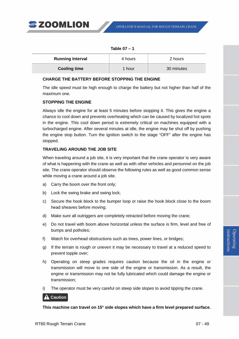
RT60 Rough Terrain Crane 07 - 49
Table 07 – 1
Running Interval 4 hours 2 hours
Cooling time 1 hour 30 minutes
CHARGE THE BATTERY BEFORE STOPPING THE ENGINE
The idle speed must be high enough to charge the battery but not higher than half of the maximum one.
STOPPING THE ENGINE
Always idle the engine for at least 5 minutes before stopping it. This gives the engine a chance to cool down and prevents overheating which can be caused by localized hot spots in the engine. This cool down period is extremely critical on machines equipped with a turbocharged engine. After several minutes at idle, the engine may be shut off by pushing the engine stop button. Turn the ignition switch to the stage “OFF” after the engine has stopped.
TRAVELING AROUND THE JOB SITE
When traveling around a job site, it is very important that the crane operator is very aware of what is happening with the crane as well as with other vehicles and personnel on the job site. The crane operator should observe the following rules as well as good common sense while moving a crane around a job site.
a) Carry the boom over the front only;
b) Lock the swing brake and swing lock;
c) Secure the hook block to the bumper loop or raise the hook block close to the boom head sheaves before moving;
d) Make sure all outriggers are completely retracted before moving the crane;
e) Do not travel with boom above horizontal unless the surface is firm, level and free of bumps and potholes;
f) Watch for overhead obstructions such as trees, power lines, or bridges;
g) If the terrain is rough or uneven it may be necessary to travel at a reduced speed to prevent topple over;
h) Operating on steep grades requires caution because the oil in the engine or transmission will move to one side of the engine or transmission. As a result, the engine or transmission may not be fully lubricated which could damage the engine or transmission;
i) The operator must be very careful on steep side slopes to avoid tipping the crane.
This machine can travel on 15° side slopes which have a firm level prepared surface.
Caution
07 - 50 RT60 Rough Terrain Crane
Due to variations in surface, tire pressure, bumps, potholes, etc., we recommend that travel on side slopes be limited to 5° and that the boom be horizontal or below.
See the “ON TIRE LIFTS” instructions found later in this section for instructions on moving the crane with a load.
7. 21 “ON TIRES” LIFTS
Listed below are special precautions for “On Tires” lifts.
a) The boom shall be carried straight over the front of the crane;
b) Travel speed reduced to suit working conditions;
c) Maintain specified tire pressures;
d) Avoid sudden starts and stops;
e) Provide tag or restraint lines to snub swinging of the load;
f) Keep the load as close to ground as possible;
g) Lock the swing brake and swing lock;
h) Travel must be on a smooth level surface that is capable of supporting the weight of the loaded crane. The travel surface must also be free of holes or debris that can cause crane instability.
These precautions are necessary to prevent a “pendulum” effect of a swinging load. The results of this happening can cause a machine tip over.
(1) Any variation from the above conditions will require the operator to consider the prevailing conditions and reduce the lift capacities accordingly. Insufficient tire pressure reduces the “ON TIRES” capacity. Attempts to pick rated capacity without properly inflated tires may cause crane to tip and/or result in damage to tires and rims;
(2) Excessive high hydraulic oil temperatures cause rapid deterioration of rubber components (hose, O-rings, etc.). If hydraulic reservoir temperature reaches 80℃(176°F), reduce the duty cycle. Stop operations as required to prevent further increase in the hydraulic oil temperature;
(3) “Creep” means the crane can be moved at a maximum speed of 1.6 KM/h for a distance of 18 M (60 ft) and then stop for 30 minutes to cool the tires. Overheating will greatly reduce the life of the tires.
Caution
Caution
RT60 Rough Terrain Crane 07 - 51
7. 22 UNUSUAL OPERATING CONDITIONS
Special problems in maintenance and operation are caused by unusual conditions such as extremes in heat, cold and humidity, high altitude, salt water, and dusty or sandy work sites. When operating under such conditions, special precautions must be taken to prevent damage, minimize wear, and avoid component deterioration.
EXTREME COLD
In periods of extreme cold, the problems of freeze damage, inadequate lubrication and battery failure may become particularly troublesome. With the onset of very cold weather, it is advisable to “winterize” the crane by servicing the cooling system and switching to the lubricants recommended for cold weather usage. Follow the recommendations in this manual when the crane must be operated in very cold conditions.
a) To prevent freeze damage to the cooling system and cracking of the engine block or head, drain and flush the cooling system. Clean the radiator exterior, making certain the air passages through the core and the cooling fins are free of foreign matter. Refill the cooling system, adding an anti-freeze solution recommended by the engine manufacturer in an amount and strength appropriate to the anticipated temperatures. A corrosion inhibitor is recommended.
Never use a chromate base corrosion inhibitor when the coolant contains ethylene glycol. Use only non-chromate base inhibitors. Chromate base inhibitors reacting with ethylene glycol can produce chromium hydroxide, commonly known as “green slime”. This substance reduces the heat transfer rate and can cause serious engine overheating.
b) Inspect the thermostat, clamps, radiator hoses and radiator core for proper condition. Replace the parts if necessary;
c) Condensation in the fuel tank contaminates the fuel supply with water, which can freeze in the fuel lines and block the fuel flow to the engine. To minimize this possibility, keep the tank as full as is practical during cold weather. This may entail refilling the tank more frequently than usual, but the inconvenience is small compared to clearing a blocked fuel line. If water should be noticed in the fuel supply, drain the tank and refill it with uncontaminated fuel;
d) Lubricate the crane with the lubricants recommended for cold weather operation. If necessary, change the engine oil and other lubricants in order to conform to the recommendations;
e) The battery is more likely to sustain freeze damage if not kept fully charged because its electrolyte will freeze at a higher temperature than that in a fully charged battery. Be certain the battery is charging when the engine is running and use an external charger to restore full charge when the crane is not being operated.
During extremely cold weather, it is advisable to remove and store the battery in a heated area when the crane is to remain idle overnight or for any extended period;
Caution
07 - 52 RT60 Rough Terrain Crane
f) AIR BRAKES At least once a day, drain the water accumulation from the air tanks;
g) Special attention must be given to the hydraulic oil during very cold weather;
NEVER ENGAGE THE HYDRAULIC PUMP AND ACTUATE THE HYDRAULIC SYSTEM BEFORE THE HYDRAULIC OIL IS WARM. Cold, sluggish oil can cause pump cavitation. If the crane is not equipped with a reservoir immersion heater and running the oil over relief will not warm it sufficiently to prevent pump cavitation with the engine running very slowly, cease attempts to engage the main pump until an external heat source can be obtained.
Once the reservoir is warm to the touch, actuate the hydraulic system by engaging the hydraulic pump. Continue warming the oil and slowly cycle all crane functions, actuating all cylinders in turn, swing the upperstructure and operating the winches in both directions.
The hydraulic oil may be run over relief to aid in the warm-up process. To do this, actuate a function, allow the cylinders involved to reach the limits of their travel and hold the control in the engaged position for a few seconds. When running hydraulic oil over relief to warm it, be sure to restrict the flow to as slow a speed as possible by moderating pressure on the controls being engaged and running the engine at low speed.
h) At the end of the work period, or whenever the crane is to be left idle for extended periods, prevent it from being frozen to the ground by parking it on a wood, concrete, asphalt or mat surface.
EXTREME HEAT
Like extreme cold, requires that precautions be taken with respect to the cooling system, the battery and lubrication. Protect the crane by performing the following recommended procedures:
a) High temperatures necessitate the use of lubricants which are both more viscous and which resist deterioration at higher operating temperatures. Refer to the Operator’s Manual and lubricate the crane using the lubricants recommended for the expected temperatures. Crankcase oil is particularly important because it helps dissipate heat. Check the oil level frequently and add oil as necessary to maintain required level. Too little oil will hinder heat dissipation;
b) To ensure proper coolant circulation, drain and flush the cooling system, clean any foreign matter from the radiator cooling fins and through core air passages, replace defective hoses, tighten hose clamps, tension the water pump drive belt properly, eliminate any leaks detected and fill the system with a 50% solution of ethylene glycol. A corrosion inhibitor is recommended.
Engine overheating due to loss of coolant will most often be corrected by SLOWLY adding coolant while the engine is running at FAST IDLE. Should this fail to correct the problem, drain and flush the system and refill with fresh coolant (50% solution of
Caution
RT60 Rough Terrain Crane 07 - 53
ethylene glycol) and a corrosion inhibitor. Water containing more than small concentrations of salt or minerals should not be used in the cooling system. Salt facilitates corrosion and minerals deposited on the coolant passage walls. Both processes inhibit proper cooling;
c) Air circulation around the engine and battery must not be restricted. Keep air intake and exhaust openings clear of leaves, paper or other foreign matter which may restrict air flow;
d) Keep the engine clean of dirt, grease and other substances which inhibit heat dissipation;
e) Use sound judgment in operating the engine. Avoid the two extremes of racing and lugging.
Advance the throttle only enough to handle the load, yet be certain that the engine speed is high enough to maintain adequate fan speed for cooling. Run the engine only when engaged in work operations or when traveling the crane. Avoid prolonged periods at idle and shut the engine down if operations are interrupted.
SANDY OR DUSTY WORK SITES
The presence of large amounts of sand or dust at the work site can contribute to accelerated component wear. Either substance will act as an abrasive when deposited on moving parts of the crane. The problem is combated by more frequent lubrication and by the servicing of breathers and filters at shorter intervals. Follow the recommendations below when operating in sand or dust on a regular basis.
a) Keep sand and dust out of the hydraulic system by keeping the reservoir filler cap tight and servicing the hydraulic system filters frequently;
b) The fuel system should be kept free of sand and dust by keeping the tank filler cap tight and servicing the fuel filters frequently;
c) The engine breathers and air cleaner should also be serviced frequently to prevent sand and dust from entering the engine. The engine oil and oil filter should be changed at shorter than normal intervals to ensure a clean oil supply to the engine’s moving parts;
d) When lubricating the crane, thoroughly clean each grease fitting before attaching the grease gun. Pump generous amounts of grease into all lubrication points, using the fresh grease to pump out the old;
e) Adequate ground bearing support must be provided for the outrigger floats when operating in sand. Be alert for signs of carrier movement during operations.
The increased frequency of lubrication and service discussed above should be determined by observations made at the work site. Inspection will determine how long it takes for lubricants, breathers and filters to accumulate unacceptable amounts of sand or dust. The frequency of lubrication and service should be adjusted accordingly.
HIGH HUMIDITY OR SALTWATER
07 - 54 RT60 Rough Terrain Crane
In some locations, such as coastal areas, the crane may be exposed to the deteriorating effects of salt, moisture, or both. To protect exposed metallic surfaces, wiring, hoist rope, paint and other items, keep them dry and well lubricated where salt or high humidity are encountered. Follow the recommendations below when operating in these conditions:
a) Make frequent inspections for rust and corrosion and remove them as soon as they are detected. Dry and paint exposed surfaces after rust and corrosion have been removed;
b) Where paint may not be applied, such as on polished or machined surfaces, coat the area with grease or lubricant to repel water;
c) Keep bearings and their surrounding surfaces well lubricated to prevent the entry of water;
d) Hoist rope must be kept well lubricated to prevent moisture and salt from penetrating the cable strands.
HIGH ALTITUDES
Variations in altitude alter the fuel-air mixture burned in the engine and affect the engine’s performance. At high altitudes, atmospheric pressures are lower and less oxygen is available for combustion of the fuel.
Keeping the air cleaner clean and free of obstructions will help alleviate high altitude problems.
At high altitudes, closely monitor the engine temperature for overheating.
STORMS
In case of storms, take the following precautions:
a) If possible, support the load and completely retract the boom;
b) If caught by a sudden storm, switch off the engine and leave the machine;
c) If the machine is struck by lightning, check general machine operation before restarting it;
d) You must always know the weather forecasts of your area before starting work.

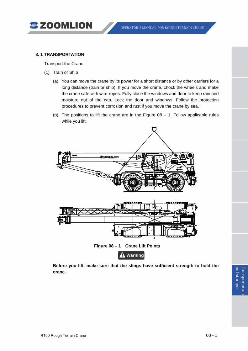
RT60 Rough Terrain Crane 08 - 1
8. 1 TRANSPORTATION
Transport the Crane
(1) Train or Ship
(a) You can move the crane by its power for a short distance or by other carriers for a long distance (train or ship). If you move the crane, chock the wheels and make the crane safe with wire-ropes. Fully close the windows and door to keep rain and moisture out of the cab. Lock the door and windows. Follow the protection procedures to prevent corrosion and rust if you move the crane by sea.
(b) The positions to lift the crane are in the Figure 08 – 1. Follow applicable rules while you lift.
Figure 08 – 1 Crane Lift Points
Before you lift, make sure that the slings have sufficient strength to hold the crane.
Warning
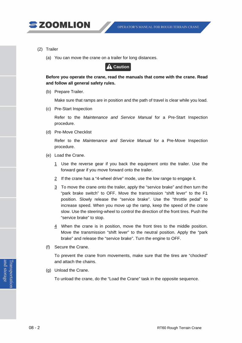
08 - 2 RT60 Rough Terrain Crane
(2) Trailer
(a) You can move the crane on a trailer for long distances.
Before you operate the crane, read the manuals that come with the crane. Read and follow all general safety rules.
(b) Prepare Trailer.
Make sure that ramps are in position and the path of travel is clear while you load.
(c) Pre-Start Inspection
Refer to the Maintenance and Service Manual for a Pre-Start Inspection procedure.
(d) Pre-Move Checklist
Refer to the Maintenance and Service Manual for a Pre-Move Inspection procedure.
(e) Load the Crane.
1 Use the reverse gear if you back the equipment onto the trailer. Use the forward gear if you move forward onto the trailer.
2 If the crane has a “4-wheel drive” mode, use the low range to engage it.
3 To move the crane onto the trailer, apply the “service brake” and then turn the “park brake switch” to OFF. Move the transmission “shift lever” to the F1 position. Slowly release the “service brake”. Use the “throttle pedal” to increase speed. When you move up the ramp, keep the speed of the crane slow. Use the steering-wheel to control the direction of the front tires. Push the “service brake” to stop.
4 When the crane is in position, move the front tires to the middle position. Move the transmission “shift lever” to the neutral position. Apply the “park brake” and release the “service brake”. Turn the engine to OFF.
(f) Secure the Crane.
To prevent the crane from movements, make sure that the tires are “chocked” and attach the chains.
(g) Unload the Crane.
To unload the crane, do the “Load the Crane” task in the opposite sequence.
Caution
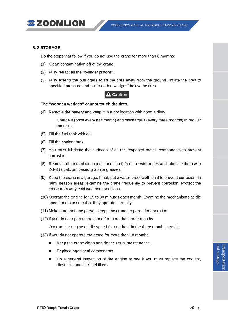
RT60 Rough Terrain Crane 08 - 3
8. 2 STORAGE
Do the steps that follow if you do not use the crane for more than 6 months:
(1) Clean contamination off of the crane.
(2) Fully retract all the “cylinder pistons”.
(3) Fully extend the outriggers to lift the tires away from the ground. Inflate the tires to specified pressure and put “wooden wedges” below the tires.
The “wooden wedges” cannot touch the tires.
(4) Remove the battery and keep it in a dry location with good airflow.
Charge it (once every half month) and discharge it (every three months) in regular intervals.
(5) Fill the fuel tank with oil.
(6) Fill the coolant tank.
(7) You must lubricate the surfaces of all the “exposed metal” components to prevent corrosion.
(8) Remove all contamination (dust and sand) from the wire-ropes and lubricate them with ZG-3 (a calcium based graphite grease).
(9) Keep the crane in a garage. If not, put a water-proof cloth on it to prevent corrosion. In rainy season areas, examine the crane frequently to prevent corrosion. Protect the crane from very cold weather conditions.
(10) Operate the engine for 15 to 30 minutes each month. Examine the mechanisms at idle speed to make sure that they operate correctly.
(11) Make sure that one person keeps the crane prepared for operation.
(12) If you do not operate the crane for more than three months:
Operate the engine at idle speed for one hour in the three month interval.
(13) If you do not operate the crane for more than 18 months:
Keep the crane clean and do the usual maintenance.
Replace aged seal components.
Do a general inspection of the engine to see if you must replace the coolant, diesel oil, and air / fuel filters.
Caution


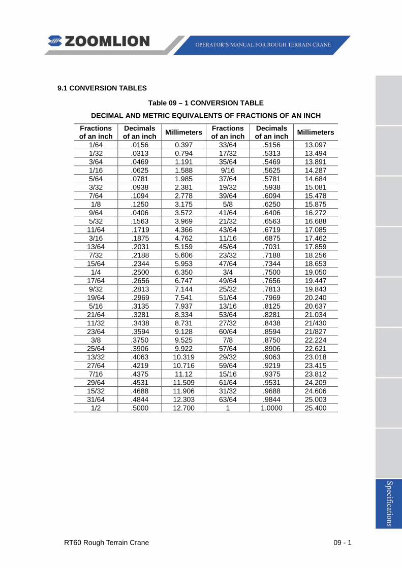
RT60 Rough Terrain Crane 09 - 1
9.1 CONVERSION TABLES
Table 09 – 1 CONVERSION TABLE
DECIMAL AND METRIC EQUIVALENTS OF FRACTIONS OF AN INCH
Fractions of an inch
Decimals of an inch Millimeters Fractions
of an inch Decimals of an inch Millimeters
1/64 .0156 0.397 33/64 .5156 13.097 1/32 .0313 0.794 17/32 .5313 13.494 3/64 .0469 1.191 35/64 .5469 13.891 1/16 .0625 1.588 9/16 .5625 14.287 5/64 .0781 1.985 37/64 .5781 14.684 3/32 .0938 2.381 19/32 .5938 15.081 7/64 .1094 2.778 39/64 .6094 15.478 1/8 .1250 3.175 5/8 .6250 15.875
9/64 .0406 3.572 41/64 .6406 16.272 5/32 .1563 3.969 21/32 .6563 16.688 11/64 .1719 4.366 43/64 .6719 17.085 3/16 .1875 4.762 11/16 .6875 17.462 13/64 .2031 5.159 45/64 .7031 17.859 7/32 .2188 5.606 23/32 .7188 18.256 15/64 .2344 5.953 47/64 .7344 18.653 1/4 .2500 6.350 3/4 .7500 19.050
17/64 .2656 6.747 49/64 .7656 19.447 9/32 .2813 7.144 25/32 .7813 19.843 19/64 .2969 7.541 51/64 .7969 20.240 5/16 .3135 7.937 13/16 .8125 20.637 21/64 .3281 8.334 53/64 .8281 21.034 11/32 .3438 8.731 27/32 .8438 21/430 23/64 .3594 9.128 60/64 .8594 21/827 3/8 .3750 9.525 7/8 .8750 22.224
25/64 .3906 9.922 57/64 .8906 22.621 13/32 .4063 10.319 29/32 .9063 23.018 27/64 .4219 10.716 59/64 .9219 23.415 7/16 .4375 11.12 15/16 .9375 23.812 29/64 .4531 11.509 61/64 .9531 24.209 15/32 .4688 11.906 31/32 .9688 24.606 31/64 .4844 12.303 63/64 .9844 25.003 1/2 .5000 12.700 1 1.0000 25.400
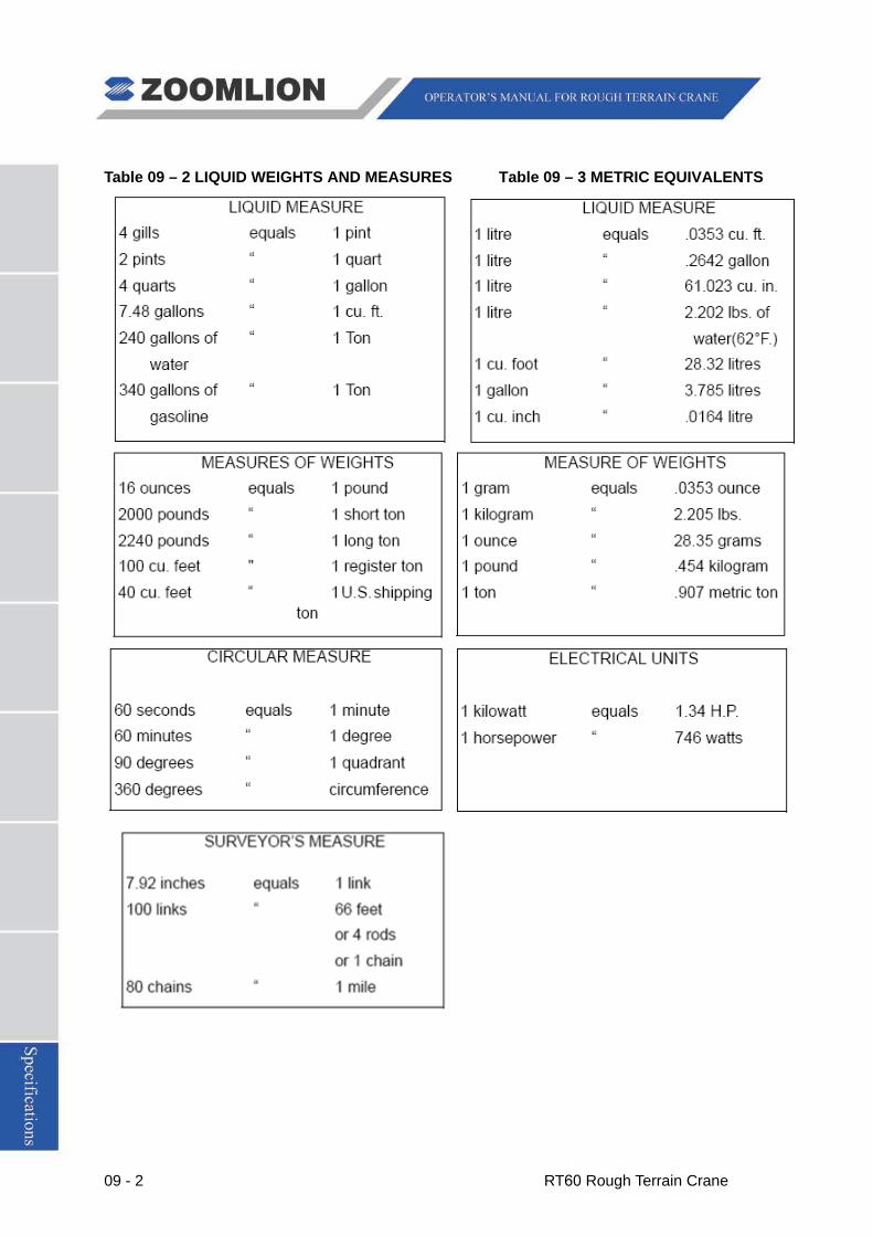
09 - 2 RT60 Rough Terrain Crane
Table 09 – 2 LIQUID WEIGHTS AND MEASURES Table 09 – 3 METRIC EQUIVALENTS

RT60 Rough Terrain Crane 09 - 3
9.2 AVERAGE WEIGHT OF MATERIALS
Table 09 – 4 AVERAGE WEIGHT OF MATERIALS
KILOGRAM PER CUBIC METER
Metals, alloys, ores Earth
Aluminum, cast-hammered 2675.31 Clay, dry 1021.482
Brass, cast-rolled 8658.276 Clay, damp, plastic 1783.54
Bronze 8252.926 Clay & gravel, dry 1621.4
Copper, cast-rolled 9014.984 Earth, dry loose 1232.264
Gold, cast-hammered 19537.87- Earth, dry packed 1540.3395
Iron, gray-cast 7166.588 Earth, moist loose 1264.692
Iron slag 2788.808 Earth, moist packed 1556.544
Lead 11511.94 Earth, mud flowing 1751.112
Manganese 7701.65 Earth, mud packed 1864.61
Mercury 13733.258 Riprap, limestone, sandstone 1297.12
Nickel 8706.918 & shale -1702.47
Steel 7798.934 - 7928.646 Sand, gravel, dry loose 1459.26-1702.47
Tin, cast-hammered 7442.226 Sand, gravel, dry packed 1621.4-1945.68
Tin, cast-hammered 7442.226 Sand, gravel, wet 2042.964
Tungsten 19456.8
Zinc, cast-rolled 7134.16
Excavations in water
Sand or gravel 972.84
Sand or gravel & clay 1053.91
Masonry Clay 1297.12
Ashlar masonry* 2318.602 - 2626.668 River mud 1459.26
Rubble masonry* 2221.318 - 2529.384 Soil 1134.98
Dry rubble masonry* 1783.54 - 2107.82 Stone riprap 1053.91
Granite, Syenite, Gneiss,
Limestone, Sandstone, Bluestone
Brick Masonry 1670.042 - 2075.392 Stone, quarried, piled
Concrete masonry 1621.4 - 2075.392 Basalt, granite, gneiss 1556.544
Portland cement 3177.944 Limestone, marble, quartz 1540.33
Portland cement, loose 1524.116 Sandstone 1329.548
Lime, gypsum, loose 859.342 - 1037.696 Shale 1491.688 Mortar, lime, set 1670.042 Greenstone, hornblende 1734.898
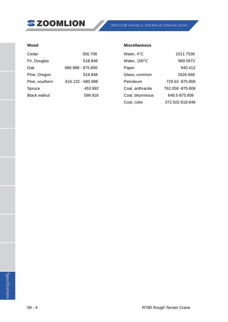
09 - 4 RT60 Rough Terrain Crane
Wood Miscellaneous
Cedar 356.708 Water, 4°C 1011.7536
Fir, Douglas 518.848 Water, 100°C 969.5972
Oak 680.988 - 875.606 Paper 940.412
Pine, Oregon 518.848 Glass, common 2626.668
Pine, southern 616.132 - 680.988 Petroleum 729.63 -875.606
Spruce 453.992 Coal, anthracite 762.058 -875.606
Black walnut 599.918 Coal, bituminous 648.5-875.606
Coal, coke 372.922-518.848
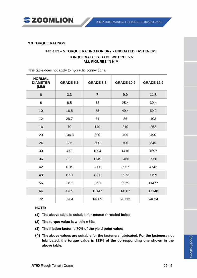
RT60 Rough Terrain Crane 09 - 5
9.3 TORQUE RATINGS
Table 09 – 5 TORQUE RATING FOR DRY - UNCOATED FASTENERS
TORQUE VALUES TO BE WITHIN ± 5% ALL FIGURES IN N·M
This table does not apply to hydraulic connections.
NORMAL DIAMETER
(MM) GRADE 5.6 GRADE 8.8 GRADE 10.9 GRADE 12.9
6 3.3 7 9.9 11.8
8 8.5 18 25.4 30.4
10 16.5 35 49.4 59.2
12 28.7 61 86 103
16 70 149 210 252
20 136.3 290 409 490
24 235 500 705 845
30 472 1004 1416 1697
36 822 1749 2466 2956
42 1319 2806 3957 4742
48 1991 4236 5973 7159
56 3192 6791 9575 11477
64 4769 10147 14307 17148
72 6904 14689 20712 24824
NOTE:
(1) The above table is suitable for coarse-threaded bolts;
(2) The torque value is within ± 5%;
(3) The friction factor is 70% of the yield point value;
(4) The above values are suitable for the fasteners lubricated. For the fasteners not lubricated, the torque value is 133% of the corresponding one shown in the above table.
09 - 6 RT60 Rough Terrain Crane
9.4 TECHNICAL SPECIFICATION
INTRODUCTION
RT60 rough terrain crane is of wide tread, short wheelbase, high stability, small turning radius and 360° swing function, which can carry out “On Tires” Lifts in narrow areas and has the ability to pick-and-carry loads.
It can be widely used in construction building sites, oil fields, warehouses, freight yards and logistics bases etc., to carry out lifting work, short distance transit and pick-and-carry operations in narrow working areas.
RT60 rough terrain crane consists of the superstructure and special purpose chassis, including power system, drive system, suspension system, steering system, brake system, hoist gear, luffing gear, swing gear, boom system, turntable, chassis frame, outrigger, hydraulic system, electrical system and cab etc.
Distinguishing characteristics:
Max. rated lifting capacity: 66.1 tn at 9.2 ft. (60 t at 3 m) radius
Max. lifting height: 148.95 ft. (45.4 m)
Max. traveling speed: 24.23 mph (39 km/h)
Three steering modes: 2-wheel steer (front wheel), 4-wheel steer and Crab steer
Overall dimensions: 44.8 ft. x 10.8 ft. x 12.3 (13662 × 3300 × 3750 mm) (Refer to Figure 09 – 1)
Deadweight: 48.8 tn (44.26 t)
Ability to pick-and-carry loads
Rough terrain travel performance

RT60 Rough Terrain Crane 09 - 7
Fig. 09 – 1 OVERALL VIEW - RT60 ROUGH TERRAIN CRANE
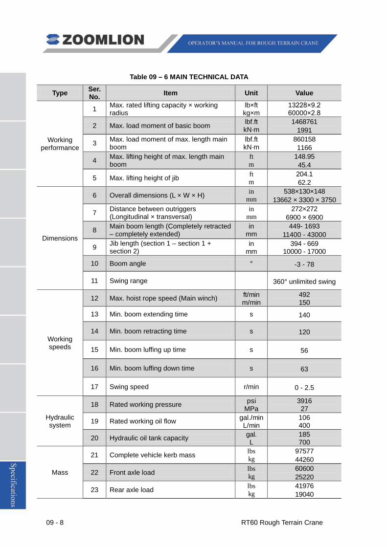
09 - 8 RT60 Rough Terrain Crane
Table 09 – 6 MAIN TECHNICAL DATA
Type Ser. No. Item Unit Value
Working performance
1 Max. rated lifting capacity × working radius
lb×ft kg×m
13228×9.260000×2.8
2 Max. load moment of basic boom lbf.ft kN·m
1468761 1991
3 Max. load moment of max. length main boom
lbf.ft kN·m
860158 1166
4 Max. lifting height of max. length main boom
ft m
148.95 45.4
5 Max. lifting height of jib ft m
204.1 62.2
Dimensions
6 Overall dimensions (L × W × H) in mm
538×130×148 13662 × 3300 × 3750
7 Distance between outriggers (Longitudinal × transversal)
in mm
272×272 6900 × 6900
8 Main boom length (Completely retracted – completely extended)
in mm
449- 1693 11400 - 43000
9 Jib length (section 1 – section 1 + section 2)
in mm
394 - 669 10000 - 17000
10 Boom angle ° -3 - 78
11 Swing range 360° unlimited swing
Working speeds
12 Max. hoist rope speed (Main winch) ft/min m/min
492 150
13 Min. boom extending time s 140
14 Min. boom retracting time s 120
15 Min. boom luffing up time s 56
16 Min. boom luffing down time s 63
17 Swing speed r/min 0 - 2.5
Hydraulic system
18 Rated working pressure psi MPa
3916 27
19 Rated working oil flow gal./min L/min
106 400
20 Hydraulic oil tank capacity gal. L
185 700
Mass
21 Complete vehicle kerb mass lbs kg
97577 44260
22 Front axle load lbs kg
60600 25220
23 Rear axle load lbs kg
41976 19040
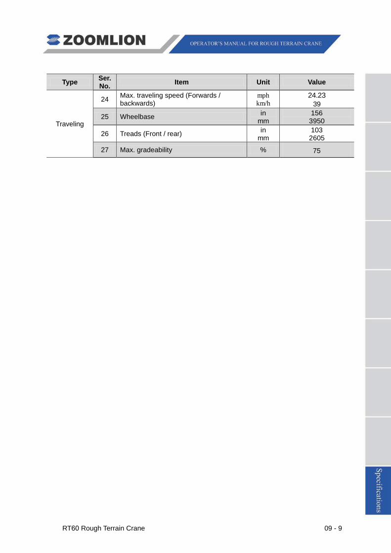
RT60 Rough Terrain Crane 09 - 9
Type Ser. No. Item Unit Value
Traveling
24 Max. traveling speed (Forwards / backwards)
mph km/h
24.23 39
25 Wheelbase in mm
156 3950
26 Treads (Front / rear) in mm
103 2605
27 Max. gradeability % 75
09 - 10 RT60 Rough Terrain Crane
STANDARD SUPERSTRUCTURE EQUIPMENT
1) BOOM
U-shaped boom welded from high-strength steel, 1 basic boom and 4 telescopic sections. The telescoping system consists of two single stage telescoping cylinders with 2 sets of wire ropes used to extend and retract the telescopic sections synchronically. The telescoping cylinder is equipped with a plunge-jointed balance valve.
Five sheaves are welded to the telescopic section 4. The crane incorporates a “Quick Reeving” boom head and block which do not require removal of the wedge socket from the rope in order to change the reeving. The rooster sheave is optional.
Min. main boom length: 37.4 ft. (11400 mm)
Max. main boom length: 141.1 ft. (43000 mm)
Max. boom extending time: About 140 s
2) JIB
One side stow swing-on lattice type jib and one inserted box type jib. The box type jib can be secured into the lattice one. Single sheave mounted on jib head.
It remains stowed on the side of boom not in used.
Offset: 0°, 20° and 40°
Jib length: 32.8 ft – 60.8 ft (10 m – 17 m)
3) LUFFING GEAR
Rear-mounted single luffing cylinder with two-way balance valve
Luff angle: -3° - 78°
Luff speed: -3° - 78° / 56 s
RT60 Rough Terrain Crane 09 - 11
4) HOIST GEAR
4.1) MAIN AND AUXILIARY WINCHES
The main and auxiliary winches are all equipped with variable axial plunger hydraulic motor and planetary reducer.
The winches are driven by the hydraulic motor with planetary reducer to lift or lower the load.
4.2) WIRE ROPE
Torsion resistant hoist rope
Max. line pull: 15737 lbf (70 kN)
Max. hoist rope speed: 492 ft/min (150 m/min) (At the 4th
Rope diameter: Φ 0.75 in (Φ19 mm)
layer)
Rope length: 656 ft (200 m)
4.3) HOOK BLOCK
60 tn (60 t) rotatable main hook with 5 sheaves and hook latch can be secured at the front section of turntable.
6.1 tn (5.5 t) rotatable auxiliary hook with single sheave used for rooster sheave and jib operations can also be secured to the hook latch and stored in the auxiliary hook holder if not required.
5) SWING GEAR
It consists of hydraulic motor, planetary gear reducer, pinion gear and swing bearing etc. Via the planetary gear reducer, the hydraulic motor drives the pinion gear to rotate and makes the swing bearing outer ring rotate around its inner toothed ring fixed on chassis frame, providing superstructure with 360° unlimited swing.
Hydraulically controlled normally-closed brake, with controllable free swing function and pneumatic swing lockout device.
Swing speed: 0 – 2.5 r/min
6) TURNTABLE
Has wall-type construction.
09 - 12 RT60 Rough Terrain Crane
7) HYDRAULIC SYSTEM
7.1) OIL PUMP
One double gear pump for boom telescope, luffing and hoist. One double gear pump for outriggers, swing gear, steering system and optional equipment such as air conditioning.
7.2) CONTROL VALVE
Pilot-operated 4-section proportional valve, with adjustable relief valve.
7.3) PIPELINE
The pipelines are equipped with an air-cooled oil cooler driven by hydraulic motor and a pressure detecting port. System pressure can be read from the gauges on the dash.
7.4) HYDRAULIC RESERVOIR
Capacity: About 185 gal (700 L)
7.5) FILTER
Return line filter with the filtering accuracy of 10 µ
8) CRANE CONTROLS
The superstructure movements are controlled by two hydraulically controlled joysticks on both sides of operator’s seat (comply with ISO standard requirements). The left joystick controls swing and auxiliary winch movements. The right joystick controls luffing and main winch movements. The boom extend / retract pedal controls boom extension and retraction.
The joysticks and the boom extend / retract pedal can provide the crane with simultaneous movements
9) CAB
There is only one cab for RT60 rough terrain crane. It can be used as operator’s cab as well as driver’s cab. The left side-mounted cab is equipped with an operator’s seat.
The crane adopts EATON (Ji’ning) hydraulic steering gear, Yuxin (He’nan) special air conditioning and Jingwei (Beijing) special cab heater.
Exhaust emission complies with the requirements of Europe Environment Protection.
There are two control boxes on both sides of operator’s seat. The left / right control box can be pulled up. The controls of superstructure are arranged according to the requirements of ASME B30.5-2007 standard and comply with ISO (International Organization for Standardization) standard.
CAB DIMENSIONS
Length: 90.6 in ± 0.2 (2300 mm ± 5 mm)
Width: 41.7 in ± 0.2 (1060 mm ± 5 mm)
Height: 65.6 in ± 0.2 (1665 mm ± 5 mm)

RT60 Rough Terrain Crane 09 - 13
10) RATED CAPACITY INDICATOR (RCI)
Rated Capacity Indicator with visual and audible warning system and automatic function disconnects.
If the actual load approaches the rated one, the buzzer sends out visual and audible warning. If the actual load reaches the rated one, all dangerous movements are switched off automatically.
The rated capacity indicator also can limit the working range (including working radius, boom angle, lifting height and swing range etc.).
Pictographic display includes boom angle, moment ratio, boom length, defaulted hook weight, actual working radius, swing angle, actual load, allowable load, jib offset, line parts, boom status, outrigger information, “On Tires” indication and percentage of allowable load and hydraulic system pressure registered by bar graph.
11) OUTRIGGERS
H-type hydraulic outriggers can be operated in the cab simultaneously or independently. Each vertical jack is equipped with a two-way hydraulic lock to ensure that the outriggers can be secured reliably during working or traveling.
Outrigger boxes are directly welded onto the chassis frame.
The outriggers can be completely extended, intermediately extended or completely retracted.
Longitudinal distance between outriggers: 22.6 ft (6900 mm)
Transversal distance between outriggers:
Completely extended: 22.6 ft (6900 mm)
Intermediately extended: 15.8 ft (4830 mm)
Completely retracted: 9.1 ft (2760 mm)

09 - 14 RT60 Rough Terrain Crane
STANDARD CHASSIS EQUIPMENT
1) TYPE
Left side-mounted cab, rear mounted engine
Drive mode: 4 x 2 and 4 x 4
2) CHASSIS FRAME
Integral box-type construction welded by high-strength steel
3) ENGINE
3.1) MODEL
CUMMINS QSB6.7
3.2) TYPE
Four stroke cycles, 6-cylinder diesel, direct injection, water-cooled, turbocharged
3.3) PERFORMANCE
Max. output power: 160 KW / 2500 RPM
Max. output torque: 649 ft.lb (880 N·m) / 1500 RPM
4) DRIVE SYSTEM
Electrically controlled automatic hydraulic transmission, with two driving modes of “2-wheel drive” and “4-wheel drive”.
Several speeds forward and reverse with electro-hydraulic power shift and automatic locking mechanism.
The hydraulic oil pump and steering oil pump directly take off power from the transmission.
5) AXLE
5.1) FRONT AXLE
Steering and driving axle, rigidly mounted to chassis frame, with planetary reducer and brake.
5.2) Rear axle
Total oscillation steering and driving axle, with planetary reducer and brake.
6) STEERING SYSTEM
Hydraulic four-wheel full power steering for two-wheel, four-wheel coordinated, or four-wheel crab steer is easily controlled by steering wheel.
Provides 3 steering modes:
2-wheel steer – front wheel steer
4-wheel steer – all-wheel steer
4-wheel steer – crab steer
RT60 Rough Terrain Crane 09 - 15
7) SUSPENSION SYSTEM
Front axle: rigidly mounted to chassis frame
Rear axle: oscillation axle, connecting to chassis frame via hydraulic suspension cylinder
8) BRAKE SYSTEM
8.1) SERVICE BRAKE
Hydraulically controlled disc brake on all wheels
8.2) PARKING BRAKE
Electrically controlled front axle mounted spring-set, air released parking brake
9) ELECTRICAL SYSTEM
24 Volt DC
2 batteries, each with 120 Ah
10) FUEL TANK
Capacity: 79 gal (300 L)
11) Tire
Size: 26.5 - 25 32PR
09 - 16 RT60 Rough Terrain Crane
SAFETY DEVICES
1) Rated capacity indicator (RCI)
2) Rotating beacon and horn
3) Anti-Two Block devices
4) 3rd
5) Balance valve
wrap
6) Hydraulic lock
7) Hydraulic safety valve
8) Swing brake
9) Swing lockout device
10) Boom angle indicator
11) Outrigger beam retaining pin
12) Emergency stop button
13) Winch speed sensor