Embed Size (px)
Citation preview
Mi-T-M ECF Series Operator's Manual �
OPERATORS MANUAL FOR Mi-T-M®
ECF-0M10ELECTROCOAGULATION
AND FLOCCULATION SYSTEM
©Copyright 2008, Mi-T-M Corporation® 37-�009-072408
CAUTIONRISK OF INJURY!
READ MANUAL BEFORE OPERATING!This manual is an important part of the Electrocoagulation System
and must remain with the unit when you sell it!
2 Mi-T-M® ECF Series Operator's Manual
Contents
INTRODUCTION............................................................................................................................... 3
CONTeNTs.Of.THe.eleCTROCOagUlaTION.sysTem............................................................ 4
speCIfICaTIONs............................................................................................................................. 4
pURpOse......................................................................................................................................... 4
ImpORTaNT.safeTy.WaRNINgs................................................................................................. 5. RIsK.Of.eleCTRIC.sHOCK.OR.eleCTROCUTION..........................................................................…5. RIsK.Of.eXplOsION.OR.fIRe...........................................................................................................…6. RIsK.Of.BURsTINg.............................................................................................................................…6. RIsK.Of.BURNs...................................................................................................................................…6. RIsK.fROm.mOVINg.paRTs...............................................................................................................…7. RIsK.Of.BODIly.INJURy.....................................................................................................................…7
eleCTROCOagUlaTION..sysTem.flOW.CHaRT..................................................................... 8
eleCTROCOagUlaTION..sysTem.feaTURes.......................................................................... 9
INsTallaTION............................................................................................................................... 10. aTTIRe.................................................................................................................................................…10. INsTallaTION....................................................................................................................................…10. pRe-OpeRaTION.CHeCKlIsT..........................................................................................................…12. pRe-OpeRaTIONs.pROCeDURes...................................................................................................…13. OpeRaTION.pROCeDURes..............................................................................................................…13maINTeNaNCe.................................................................................................................. 14. CleaNINg.pROCeDURe...................................................................................................................…14. WINTeRIZINg......................................................................................................................................…15
TROUBle.sHOOTINg..................................................................................................16-19
WaRRaNTy.................................................................................................................................... 20
NOTes............................................................................................................................................ 21
Mi-T-M ECF Series Operator's Manual 3
Congratulations on the purchase of your new Mi-T-M Electrocoagulation System! You can be assured your Mi-T-M Electrocoagulation System was constructed and designed with quality and performance in mind. Each component has been rigorously tested to ensure the highest level of acceptance.This operator's manual was compiled for your benefit. By reading and following the simple safety, installation, operation, maintenance and troubleshooting steps described in this manual, you will receive years of trouble free operation from your new Mi-T-M Electrocoagulation System. The contents of this manual are based on the latest product information available at the time of publication. Mi-T-M reserves the right to make changes in price, color, materials, equipment, specifications or models at any time without notice.
!.ImpORTaNT.!These.paragraphs.are.surrounded.by.a."safeTy.aleRT.BOX"...This.box.is.used.to.designate.and.emphasize.safety.Warnings.that.must.be.followed.when.operating.this.electrocoagulation..system...accompanying.the.safety.Warnings.are."signal.words".which.designate.the.degree.or.level.of.hazard.seriousness...The."signal.words".used.in.this.manual.are.as.follows:
DANGER:. Indicates.an.imminently.hazardous.situation.which,.if.not.avoided,.WIll.. .. . . result.in.death.or.serious.injury..WARNING:.Indicates.a.potentially.hazardous.situation.which,.if.not.avoided,.COUlD.. .. . . result.in.death.or.serious.injury..CAUTION:. Indicates.a.potentially.hazardous.situation.which,.if.not.avoided.may.. . .. . . result.in.minor.or.moderate.injury.
The.symbols.set.to.the.left.of.this.paragraph.are."safety.alert.symbols"...These.symbols.are.used.to.call.attention.to.items.or.procedures.that.could.be.dangerous.to.you.or.other.persons.using.this.equipment.
alWays.pROVIDe.a.COpy.Of.THIs.maNUal.TO.aNyONe.UsINg.THIs.eQUIpmeNT...ReaD.all.INsTRUCTIONs.BefORe.OpeRaTINg.THIs.eleCTROCOagUlaTION..sysTem.aND.espeCIally.pOINT.OUT.THe."safeTy.WaRNINgs".TO.pReVeNT.THe.pOssIBIlITy.Of.peRsONal.INJURy.TO.THe.OpeRaTOR..
Once the unit has been uncrated, immediately write in the serial number of your unit in the space provided below.
seRIal.NUmBeR_________________________________
Inspect for signs of obvious or concealed freight damage. If damage does exist, file a claim with the transportation company immediately. Be sure that all damaged parts are replaced and that the mechanical and electrical problems are corrected prior to operation of the unit. If you require service, contact Mi-T-M Customer Service.
CUSTOMER SERVICECALL OUR TOLL-FREE NUMBER
for the Sales or Service Center nearest you!800-553-9053
Please have the following information available for all service calls: �. Model Number 2. Serial Number 3. Date and Place of Purchase
INTRODUCTION
4 Mi-T-M® ECF Series Operator's Manual
CONTeNTs.Of.THe.eleCTROCOagUlaTION.sysTem
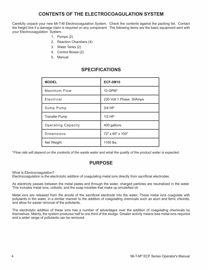
Carefully unpack your new Mi-T-M Electrocoagulation System. Check the contents against the packing list. Contact the freight line if a damage claim is required on any component. The following items are the basic equipment sent with your Electrocoagulation System.
�. Pumps (2)2. Reaction Chambers (4)3. Water Tanks (2)4. Control Boxes (2)5. Manual
speCIfICaTIONs
pURpOse
What is Electrocoagulation?Electrocoagulation is the electrolytic addition of coagulating metal ions directly from sacrificial electrodes.
As electricity passes between the metal plates and through the water, charged particles are neutralized in the water. This includes metal ions, colloids, and the soap micelles that make up emulsified oil.
Metal ions are released from the anode of the sacrificial electrode into the water. These metal ions coagulate with pollutants in the water, in a similar manner to the addition of coagulating chemicals such as alum and ferric chloride, and allow for easier removal of the pollutants.
The electrolytic addition of these ions has a number of advantages over the addition of coagulating chemicals by themselves. Mainly, the system produces half to one third of the sludge. Greater activity means less metal ions required and a wider range of pollutants can be removed.
mODel eCf-0m10
Maximum Flow �0 GPM*
Electr ical 230 Volt � Phase 30Amps
Sump Pump 3/4 HP
Transfer Pump �/2 HP
Operat ing Capaci ty 400 gallons
Dimensions 72" x 60" x �00"
Net Weight ��00 lbs.
*Flow rate will depend on the contents of the waste water and what the quality of the product water is expected.
Mi-T-M ECF Series Operator's Manual 5
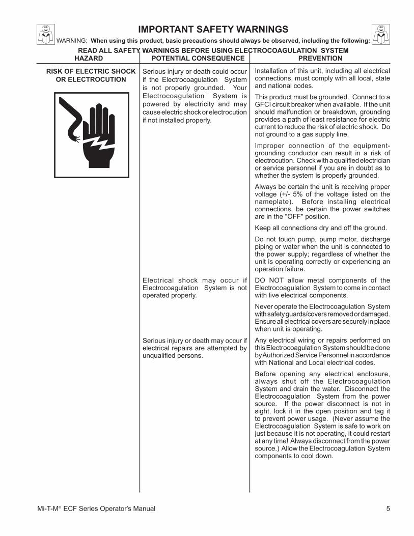
ImpORTaNT.safeTy.WaRNINgsWARNING:..When.using.this.product,.basic.precautions.should.always.be.observed,.including.the.following:
ReaD.all.safeTy.WaRNINgs.BefORe.UsINg.eleCTROCOagUlaTION..sysTempOTeNTIal.CONseQUeNCe pReVeNTION
Serious injury or death could occur if the Electrocoagulation System is not properly grounded. Your Electrocoagulation System is powered by electricity and may cause electric shock or electrocution if not installed properly.
Electrical shock may occur if Electrocoagulation System is not operated properly.
Serious injury or death may occur if electrical repairs are attempted by unqualified persons.
Installation of this unit, including all electrical connections, must comply with all local, state and national codes.
This product must be grounded. Connect to a GFCI circuit breaker when available. If the unit should malfunction or breakdown, grounding provides a path of least resistance for electric current to reduce the risk of electric shock. Do not ground to a gas supply line.
Improper connection of the equipment-grounding conductor can result in a risk of electrocution. Check with a qualified electrician or service personnel if you are in doubt as to whether the system is properly grounded.
Always be certain the unit is receiving proper voltage (+/- 5% of the voltage listed on the nameplate). Before installing electrical connections, be certain the power switches are in the "OFF" position.
Keep all connections dry and off the ground.
Do not touch pump, pump motor, discharge piping or water when the unit is connected to the power supply; regardless of whether the unit is operating correctly or experiencing an operation failure.
DO NOT allow metal components of the Electrocoagulation System to come in contact with live electrical components.
Never operate the Electrocoagulation System with safety guards/covers removed or damaged. Ensure all electrical covers are securely in place when unit is operating.
Any electrical wiring or repairs performed on this Electrocoagulation System should be done by Authorized Service Personnel in accordance with National and Local electrical codes.
Before opening any electrical enclosure, always shut off the Electrocoagulation System and drain the water. Disconnect the Electrocoagulation System from the power source. If the power disconnect is not in sight, lock it in the open position and tag it to prevent power usage. (Never assume the Electrocoagulation System is safe to work on just because it is not operating, it could restart at any time! Always disconnect from the power source.) Allow the Electrocoagulation System components to cool down.
RIsK.Of.eleCTRIC.sHOCK.OR.eleCTROCUTION
HaZaRD
6 Mi-T-M® ECF Series Operator's Manual
Never allow any part of your body to contact the electrical motor until cooled.
pOTeNTIal.CONseQUeNCe pReVeNTION
ImpORTaNT.safeTy.WaRNINgsReaD.all.safeTy.WaRNINgs.BefORe.UsINg.eleCTROCOagUlaTION..sysTem
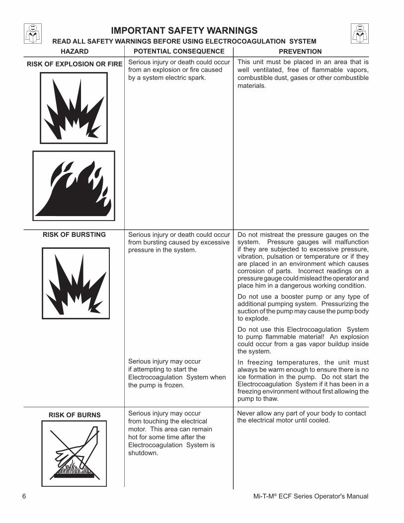
RIsK.Of.eXplOsION.OR.fIRe Serious injury or death could occur from an explosion or fire caused by a system electric spark.
This unit must be placed in an area that is well ventilated, free of flammable vapors, combustible dust, gases or other combustible materials.
HaZaRD
RIsK.Of.BURNs Serious injury may occur from touching the electrical motor. This area can remain hot for some time after the Electrocoagulation System is shutdown.
RIsK.Of.BURsTINg Serious injury or death could occur from bursting caused by excessive pressure in the system.
Serious injury may occur if attempting to start the Electrocoagulation System when the pump is frozen.
Do not mistreat the pressure gauges on the system. Pressure gauges will malfunction if they are subjected to excessive pressure, vibration, pulsation or temperature or if they are placed in an environment which causes corrosion of parts. Incorrect readings on a pressure gauge could mislead the operator and place him in a dangerous working condition.
Do not use a booster pump or any type of additional pumping system. Pressurizing the suction of the pump may cause the pump body to explode.
Do not use this Electrocoagulation System to pump flammable material! An explosion could occur from a gas vapor buildup inside the system.
In freezing temperatures, the unit must always be warm enough to ensure there is no ice formation in the pump. Do not start the Electrocoagulation System if it has been in a freezing environment without first allowing the pump to thaw.
Mi-T-M ECF Series Operator's Manual 7
RIsK.Of.BODIly.INJURy
.
Injury may occur from the Electrocoagulation System.
!SAVE THESE INSTRUCTIONS!
HaZaRD pOTeNTIal.CONseQUeNCe pReVeNTION
ImpORTaNT.safeTy.WaRNINgsReaD.all.safeTy.WaRNINgs.BefORe.UsINg.eleCTROCOagUlaTION..sysTem
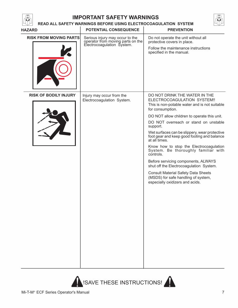
DO NOT DRINK THE WATER IN THE ELECTROCOAGULATION SYSTEM!! This is non-potable water and is not suitable for consumption.
DO NOT allow children to operate this unit.DO NOT overreach or stand on unstable support. Wet surfaces can be slippery, wear protective foot gear and keep good footing and balance at all times. Know how to stop the Electrocoagulation System. Be thoroughly familiar with controls.
Before servicing components, ALWAYS shut off the Electrocoagulation System.
Consult Material Safety Data Sheets (MSDS) for safe handling of system, especially oxidizers and acids.
Serious injury may occur to the operator from moving parts on the Electrocoagulation System.
Do not operate the unit without all protective covers in place.Follow the maintenance instructions specified in the manual.
RIsK.fROm.mOVINg.paRTs
8 Mi-T-M® ECF Series Operator's Manual
eleCTROCOagUlaTION..sysTem.flOW.CHaRTFL
OW
DIA
GR
AM
-EC
F 05
0808
-PJH
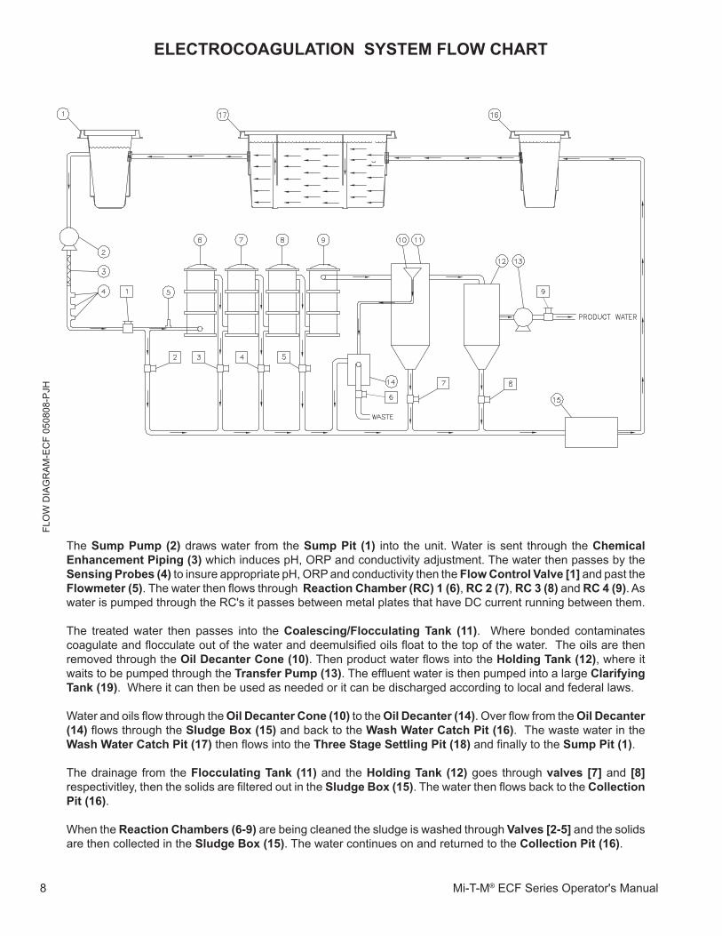
The sump.pump.(2) draws water from the sump.pit. (1) into the unit. Water is sent through the Chemical.enhancement.piping.(3) which induces pH, ORP and conductivity adjustment. The water then passes by the sensing.probes.(4) to insure appropriate pH, ORP and conductivity then the flow.Control.Valve.[1].and past the flowmeter.(5)..The water then flows through. Reaction.Chamber.(RC).1.(6), RC.2.(7), RC.3.(8) and RC.4.(9). As water is pumped through the RC's it passes between metal plates that have DC current running between them.
The treated water then passes into the Coalescing/flocculating. Tank. (11). Where bonded contaminates coagulate and flocculate out of the water and deemulsified oils float to the top of the water. The oils are then removed through the Oil.Decanter.Cone.(10). Then product water flows into the Holding.Tank.(12), where it waits to be pumped through the Transfer.pump.(13). The effluent water is then pumped into a large Clarifying.Tank.(19). Where it can then be used as needed or it can be discharged according to local and federal laws.
Water and oils flow through the Oil.Decanter.Cone.(10) to the Oil.Decanter.(14). Over flow from the Oil.Decanter.(14) flows through the sludge.Box.(15) and back to the Wash.Water.Catch.pit.(16). The waste water in the Wash.Water.Catch.pit.(17) then flows into the Three.stage.settling.pit.(18) and finally to the sump.pit.(1).
The drainage from the flocculating.Tank.(11) and the Holding.Tank.(12) goes through valves.[7] and [8].respectivitley, then the solids are filtered out in the sludge.Box.(15). The water then flows back to the Collection.pit.(16).
When the Reaction.Chambers.(6-9) are being cleaned the sludge is washed through Valves.[2-5] and the solids are then collected in the sludge.Box.(15). The water continues on and returned to the Collection.pit.(16).
Mi-T-M ECF Series Operator's Manual 9
eleCTROCOagUlaTION..sysTem.feaTUResE
C U
NIT
AS
SE
MB
LY-0
7170
8 P
JH 4 3578989898
13 1115 1416
1 2
106
6
4 12
EC UNIT ASSEMBLY 071708
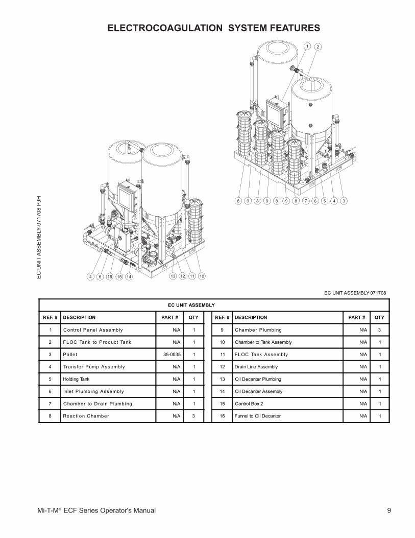
eC.UNIT.assemBly
Ref..# DesCRIpTION paRT.# QTy Ref..# DesCRIpTION paRT.# QTy
� Contro l Panel Assembly N/A � 9 Chamber P lumbing N/A 3
2 FLOC Tank to Product Tank N/A � �0 Chamber to Tank Assembly N/A �
3 Pallet 35-0035 � �� FLOC Tank Assembly N/A �
4 Transfer Pump Assembly N/A � �2 Drain Line Assembly N/A �
5 Holding Tank N/A � �3 Oil Decanter Plumbing N/A �
6 Inlet P lumbing Assembly N/A � �4 Oil Decanter Assembly N/A �
7 Chamber to Drain P lumbing N/A � �5 Control Box 2 N/A �
8 Reaction Chamber N/A 3 �6 Funnel to Oil Decanter N/A �
�0 Mi-T-M® ECF Series Operator's Manual
INsTallaTION:
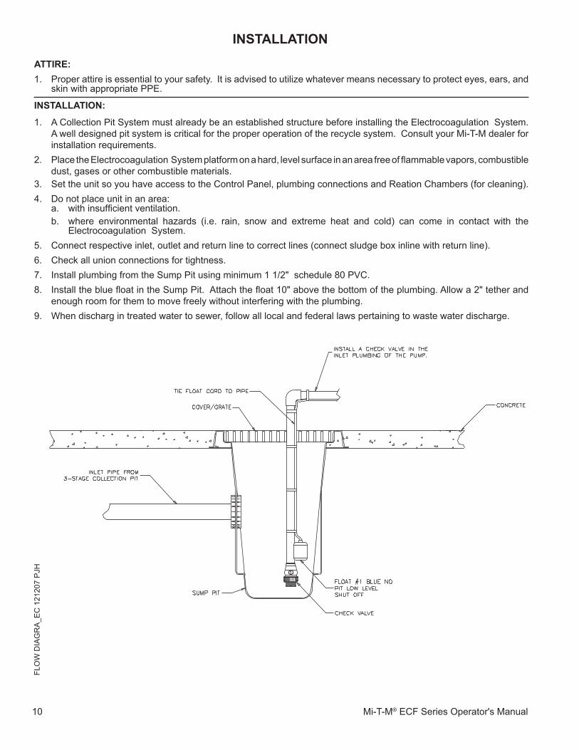
�. A Collection Pit System must already be an established structure before installing the Electrocoagulation System. A well designed pit system is critical for the proper operation of the recycle system. Consult your Mi-T-M dealer for installation requirements.
2. Place the Electrocoagulation System platform on a hard, level surface in an area free of flammable vapors, combustible dust, gases or other combustible materials.
3. Set the unit so you have access to the Control Panel, plumbing connections and Reation Chambers (for cleaning).4. Do not place unit in an area:
a. with insufficient ventilation.b. where environmental hazards (i.e. rain, snow and extreme heat and cold) can come in contact with the
Electrocoagulation System.5. Connect respective inlet, outlet and return line to correct lines (connect sludge box inline with return line).6. Check all union connections for tightness.7. Install plumbing from the Sump Pit using minimum � �/2" schedule 80 PVC.8. Install the blue float in the Sump Pit. Attach the float 10" above the bottom of the plumbing. Allow a 2" tether and
enough room for them to move freely without interfering with the plumbing.9. When discharg in treated water to sewer, follow all local and federal laws pertaining to waste water discharge.
aTTIRe:�. Proper attire is essential to your safety. It is advised to utilize whatever means necessary to protect eyes, ears, and
skin with appropriate PPE.
INsTallaTIONFL
OW
DIA
GR
A_E
C �
2�20
7 P
JH
Mi-T-M ECF Series Operator's Manual ��
INsTallaTION
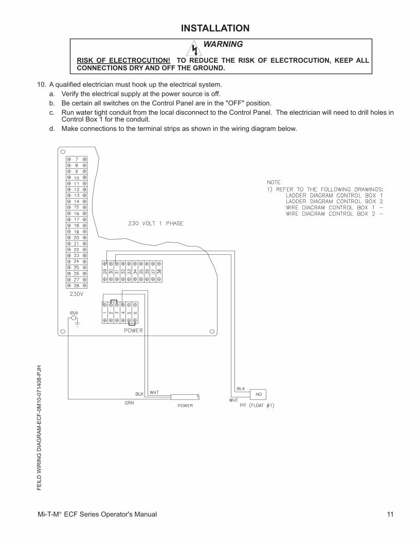
10. A qualified electrician must hook up the electrical system.a. Verify the electrical supply at the power source is off.b. Be certain all switches on the Control Panel are in the "OFF" position.c. Run water tight conduit from the local disconnect to the Control Panel. The electrician will need to drill holes in
Control Box 1 for the conduit.d. Make connections to the terminal strips as shown in the wiring diagram below.
WARNING
RIsK. Of. eleCTROCUTION!. . TO. ReDUCe. THe. RIsK. Of. eleCTROCUTION,. Keep. all.CONNeCTIONs.DRy.aND.Off.THe.gROUND...
FEIL
D W
IRIN
G D
IAG
RA
M-E
CF-
0M�0
-07�
408-
PJH
�2 Mi-T-M® ECF Series Operator's Manual
INsTallaTION.Of.pH,.ORp.aND.CONDUCTIVITy.pROBes:
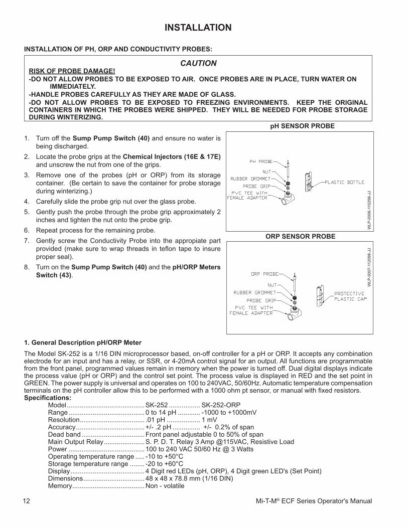
�. Turn off the sump.pump.switch.(40) and ensure no water is being discharged.
2. Locate the probe grips at the Chemical.Injectors.(16e.&.17e) and unscrew the nut from one of the grips.
3. Remove one of the probes (pH or ORP) from its storage container. (Be certain to save the container for probe storage during winterizing.)
4. Carefully slide the probe grip nut over the glass probe.5. Gently push the probe through the probe grip approximately 2
inches and tighten the nut onto the probe grip. 6. Repeat process for the remaining probe.7. Gently screw the Conductivity Probe into the appropiate part
provided (make sure to wrap threads in teflon tape to insure proper seal).
8. Turn on the sump.pump.switch.(40) and the pH/ORp.meters.switch.(43).
CAUTIONRIsK.Of.pROBe.Damage!..-DO.NOT.allOW.pROBes.TO.Be.eXpOseD.TO.aIR...ONCe.pROBes.aRe.IN.plaCe,.TURN.WaTeR.ON.............. .ImmeDIaTely...-HaNDle.pROBes.CaRefUlly.as.THey.aRe.maDe.Of.glass.-DO. NOT. allOW. pROBes. TO. Be. eXpOseD. TO. fReeZINg. eNVIRONmeNTs.. . Keep. THe. ORIgINal.CONTaINeRs.IN.WHICH.THe.pROBes.WeRe.sHIppeD...THey.WIll.Be.NeeDeD.fOR.pROBe.sTORage.DURINg.WINTeRIZINg.
ORp.seNsOR.pROBe
pH.seNsOR.pROBe
WLP
-000
6-��
0298
-JJ
WLP
-000
7-��
2098
-JJ
1..general.Description.pH/ORp.meterThe Model SK-252 is a �/�6 DIN microprocessor based, on-off controller for a pH or ORP. It accepts any combination electrode for an input and has a relay, or SSR, or 4-20mA control signal for an output. All functions are programmable from the front panel, programmed values remain in memory when the power is turned off. Dual digital displays indicate the process value (pH or ORP) and the control set point. The process value is displayed in RED and the set point in GREEN. The power supply is universal and operates on �00 to 240VAC, 50/60Hz. Automatic temperature compensation terminals on the pH controller allow this to be performed with a 1000 ohm pt sensor, or manual with fixed resistors.Specifications:
Model ..........................................SK-252 ................. SK-252-ORPRange ......................................... 0 to �4 pH ............ -�000 to +�000mVResolution ................................... .0� pH .................. � mVAccuracy ..................................... +/- .2 pH ............... +/- 0.2% of spanDead band .................................. Front panel adjustable 0 to 50% of spanMain Output Relay ......................S. P. D. T. Relay 3 Amp @��5VAC, Resistive LoadPower ......................................... �00 to 240 VAC 50/60 Hz @ 3 WattsOperating temperature range ..... -�0 to +50°CStorage temperature range ........ -20 to +60°CDisplay ........................................ 4 Digit red LEDs (pH, ORP), 4 Digit green LED's (Set Point)Dimensions ................................. 48 x 48 x 78.8 mm (�/�6 DIN)Memory .......................................Non - volatile
INsTallaTION
Mi-T-M ECF Series Operator's Manual �3
�. General Description Conductivity MeterThe Model TSC-20 is a microprocessor programmable controller that accepts a conductivity electrode as an input. Outputs are; one on-off � relay;3A mechanical contacts. The output can be programmed to operate above or below the set point. The power source is from �00 to 240 VAC, 50/60Hz free voltage there is no need to change connections for different voltages. The controller is programmable from the front panel via 3 switches, and calibration is done using two front panel adjustment pots.The front panel is a �/�6 DIN, NEMA 4X rated and mounting hardware is provided.CRU, RU approvals are standard.Specifications:
Range ......................................... 0 to �000 ppmResolution ................................... �ppmAccuracy ..................................... +/- 2% spanOutput Relay ...............................S. P. D. T. Relay 3 Amp @��5VAC, Resistive LoadPower ......................................... �00 to 240 VAC 50/60 Hz @ 3 WattsOperating temperature range ..... -�0 to +50°CStorage temperature range ........ -20 to +60°CDisplay ........................................ 4 Digit red LEDs (Conductivity), 4 Digit green LED's (Set Point)Dimensions ................................. 48 x 48 x 78.8 mm (�/�6 DIN)Memory .......................................Non - volatile
INsTallaTION
�4 Mi-T-M® ECF Series Operator's Manual
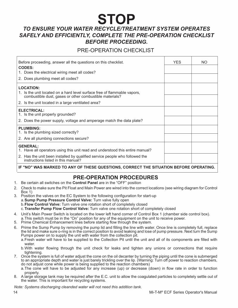
Before proceeding, answer all the questions on this checklist. YES NOCODes:�. Does the electrical wiring meet all codes?2. Does plumbing meet all codes?.lOCaTION:�. Is the unit located on a hard level surface free of flammable vapors, combustible dust, gases or other combustible materials?2. Is the unit located in a large ventilated area?.eleCTRICal:�. Is the unit properly grounded?2. Does the power supply, voltage and amperage match the data plate?.plUmBINg:�. Is the plumbing sized correctly?2. Are all plumbing connections secure?.geNeRal:�. Have all operators using this unit read and understood this entire manual?2. Has the unit been installed by qualified service people who followed the instructions listed in this manual?
If."NO".Was.maRKeD.TO.aNy.Of.THese.QUesTIONs,.CORReCT.THe.sITUaTION.BefORe.OpeRaTINg.
pRe-OpeRaTION.pROCeDURes1. Be certain all switches on the Control.panel are in the “OFF” position2. Check to make sure the Pit Float and Main Power are wired into the correct locations (see wiring diagram for Control
Box 1)3. Position the valves on the EC System to the following configuration for start-up
a. sump.pump.pressure.Control.Valve: Turn valve fully openb. flow.Control.Valve: Turn valve one rotation short of completely closedc. Transfer.pump.flow.Control.Valve: Turn valve one rotation short of completely closed
4. Unit’s Main Power Switch is located on the lower left hand corner of Control Box 1 (chamber side control box). a. This switch must be in the “On” position for any of the equipment on the unit to receive power.
5. Prime Chemical Enhancement lines before starting flow through the system.6. Prime the Sump Pump by removing the pump lid and filling the line with water. Once line is completely full, replace
the lid and make sure o-ring is in the correct position to avoid leaking and lose of pump pressure. Next turn the Sump Pumps power on to supply the unit with water from the collection pit.a. Fresh water will have to be supplied to the Collection Pit until the unit and all of its components are filled with
water.b. With water flowing through the unit check for leaks and tighten any unions or connections that require
tightening.7. Once the system is full of water adjust the cone on the oil decanter by turning the piping until the cone is submerged
to an appropriate depth and water is just barely trickling over the lip. (Warning: Turn off power to reaction chambers, do not adjust cone while power is being supplied to the reaction chambers)a. The cone will have to be adjusted for any increase (up) or decrease (down) in flow rate in order to function
properly. 8. A large storage tank may be required after the E.C. unit to allow the coagulated particles to completely settle out of
the water. This is important for recycling systems.
Note: Systems discharging cleanded water will not need this addition tank.
PRE-OPERATION CHECKLIST
sTOpTO ENsURE yOUR WATER RECyClE/TREATmENT sysTEm OpERATEs
sAfEly AND EffICIENTly, COmplETE ThE pRE-OpERATION ChECklIsT bEfORE pROCEEDING.
Mi-T-M ECF Series Operator's Manual �5
OpeRaTION.pROCeDURes1. To begin with, flow should be kept between 4-10 GPM to make sure sufficient exposure to the electrodes is provided
to the dirty water for coagulation to occur. a. If it appears that the water is cleaned to the standards that are required at 4 GPM then incrementally increase flow
so that required standards are still met.b. Once the sump pump is switched on and system is full of water, turn on power to the reaction chambers.
i. The switches will not light up until water is flowing through all of the chambers (Pressure on switch from effluent of sump pump and Switch after Reaction Chamber 4 is activated).
c. During operation keep the amperage for the Reaction Chambers at or below 50 amps. Otherwise the power sources will shut down and will not restart until the power to that reaction chamber is shut off for a 5 minutes.
2. Adjust Transfer Pump flow.Control.Valve.[49] so that water is flowing at an appropriate flowrate.
Note: if the Valve is opened to far the transfer pump will cycle excessively. Shortening the life of the pump.
Operation.pH/ORp.meter
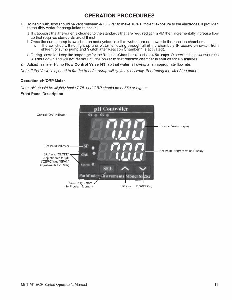
Note: pH should be slightly basic 7.75, and ORP should be at 550 or higherfront.panel.Description
Control “ON” Indicator
Set Point IndicatorSet Point Program Value Display
Process Value Display
“SEL” Key Enters into Program Memory UP Key DOWN Key
“CAL” and “SLOPE”Adjustments for pH
(“ZERO” and “SPAN”Adjustments for OPR)
�6 Mi-T-M® ECF Series Operator's Manual
OpeRaTION.pROCeDURes
KeypaD.OpeRaTION1. "SEL" key; changes upper display to the first programming menu, advances the display through the menu
and sets the programmed information into memory.2. r up arrow key, increases value displayed in the green (lower) display.3. s down arrow key, decreases value displayed in the green (lower) display.4. Press and hold "SEL" key for approximately 3 seconds and "HYS" will appear in the upper display. Hold the
"SEL" key for approximately 6 seconds and P-n� will appear.pROgRammINg
�. How to change the set point Press and hold the up r or s down arrow until the correct number appears, the new set point will be active
after 5 seconds. 2. How to change the control action (Relay activates above or below the set point) Hold the "SEL" key for approximately 6 seconds and "p-n�" will appear in the upper display, the control code
will appear in the lower display, "0" or "�" will actuate below the set point, "2" or "3" wil actuate above the set point. Press the "SEL" switch once, the value will flash, change the value with the "up" or "down" keys, and press the "SEL" key again to set it in memory. Holding the "SEL" key for approximately 2 seconds will return to normal operation.
3. How to program Hysteresis Hold the "SEL" key for approximately 3 seconds and "HYS" will appear in the upper display, the hystersis
amount will appear in the lower display, press the "SEL" key once and the amount will flash, change the amount to the desired value with the "up" or "down" keys, press "SEL" again to set it in memory. Holding the "SEL" key for approximately 2 seconds will return to normal operation.
Calibration�. How to calibrate pH The front panel has two adjustments labeled "CAL" and "SLOPE", always adjust the CAL first. Place the
pH electrode in a # 7.00 buffer solution wait for the reading to stabilize and adjust the CAL for 7.00. Rinse the electrode and place it in a #4.00 buffer solution, wait for the reading to stabilize and adjust the slpe for reading of 4.00. Calibration complete.
2. How to calibrate ORP The front panel has two adjustments labeled "ZERO" and "SPAN", the ORP controller can be calibrated with
a millivolt source subsituted for a probe. Short the input connector and adjust the SERO adjustment for reading 0000. Apply +500 mV from an accurate
mili volt source and adjust the SPAN adjustment for reading of 0500. To verify the accuracy of the ORP probe an ORP calibration kit is available from PATHFINDER INSTRUMENTS,
it consists of enough materials to do 30 tests, it contains reagents, stirrers beakers and instructions. It costs $40, ask for stock #B-125.

Mi-T-M ECF Series Operator's Manual �7
OpeRaTION.pROCeDURes
Operation.Conductivity.Controller
Note: Conductivity should be at 750 or higher for EC to work properly.
KeypaD.OpeRaTION1. "SEL" key; changes upper display to the first programming menu, advances the display through the menu
and sets the programmed information into memory.2. r up arrow key, increases value displayed in the green (lower) display.3. s down arrow key, decreases value displayed in the green (lower) display.4. Press and hold "SEL" key for approximately 3 seconds and "HYS" will appear in the upper display. Hold the
"SEL" key for approximately 6 seconds and P-n� will appear.pROgRammINg
�. How to change the set point Press and hold the up r or s down arrow until the correct number appears, the new set point will be active
after 5 seconds. 2. How to change the control action (Relay activates above or below the set point) Hold the "SEL" key for approximately 6 seconds and "p-n�" will appear in the upper display, the control code
will appear in the lower display, "0" or "�" will actuate below the set point, "2" or "3" wil actuate above the set point. Press the "SEL" switch once, the value will flash, change the value with the "up" or "down" keys, and press the "SEL" key again to set it in memory. Holding the "SEL" key for approximately 2 seconds will return to normal operation.
3. How to program Hysteresis Hold the "SEL" key for approximately 3 seconds and "HYS" will appear in the upper display, the hystersis
amount will appear in the lower display, press the "SEL" key once and the amount will flash, change the amount to the desired value with the "up" or "down" keys, press "SEL" again to set it in memory. Holding the "SEL" key for approximately 2 seconds will return to normal operation.
CalibrationHow to calibrate The front panel has two adjustments labeled "Zero" and "SPAN", always adjust the Zero first. Allow the
controller to warm up for at least 30 minutes. Place the conductivity electrode in air, wait for the reading to stabilize and adjust the "SERO" pot for a reading of 0000, place the electrode in a calibration solution of �000 ppm, allow the reading to stabilize and adjust the "SPAN" pot for a reading of �000.
Control “ON” Indicator
Set Point IndicatorSet Point Program Value Display
Process Value Display
“SEL” Key Enters into Program Memory UP Key DOWN Key
“ZERO” and “SPAN”Adjustments
�8 Mi-T-M® ECF Series Operator's Manual
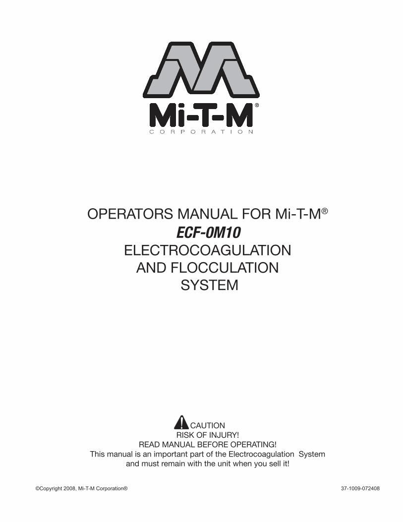
ROUTINe.maINTeNaNCeCleaning of Reaction chambers is required periodically to maintain units water treatment efficiency (should be performed when it appears that excess foam or sludge is built up on electrodes).
CleaNINg.pROCeDURe�) Power down Entire System (Main Power Switch) including all pumps and Reaction Chambers (Move all Switches
in the control Boxes to the OFF position).2) Drain the system of all water.
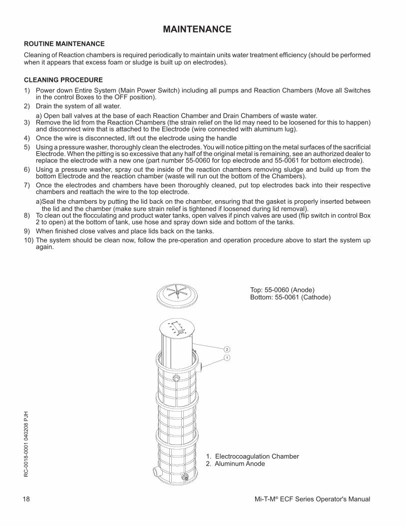
a) Open ball valves at the base of each Reaction Chamber and Drain Chambers of waste water.3) Remove the lid from the Reaction Chambers (the strain relief on the lid may need to be loosened for this to happen)
and disconnect wire that is attached to the Electrode (wire connected with aluminum lug).4) Once the wire is disconnected, lift out the electrode using the handle5) Using a pressure washer, thoroughly clean the electrodes. You will notice pitting on the metal surfaces of the sacrificial
Electrode. When the pitting is so excessive that any half of the original metal is remaining, see an authorized dealer to replace the electrode with a new one (part number 55-0060 for top electrode and 55-006� for bottom electrode).
6) Using a pressure washer, spray out the inside of the reaction chambers removing sludge and build up from the bottom Electrode and the reaction chamber (waste will run out the bottom of the Chambers).
7) Once the electrodes and chambers have been thoroughly cleaned, put top electrodes back into their respective chambers and reattach the wire to the top electrode. a) Seal the chambers by putting the lid back on the chamber, ensuring that the gasket is properly inserted between
the lid and the chamber (make sure strain relief is tightened if loosened during lid removal). 8) To clean out the flocculating and product water tanks, open valves if pinch valves are used (flip switch in control Box
2 to open) at the bottom of tank, use hose and spray down side and bottom of the tanks.9) When finished close valves and place lids back on the tanks. �0) The system should be clean now, follow the pre-operation and operation procedure above to start the system up
again.
maINTeNaNCe
2
1
RC
-00�
8-00
0� 0
4020
8 P
JH
�. Electrocoagulation Chamber2. Aluminum Anode
Top: 55-0060 (Anode)Bottom: 55-0061 (Cathode)
Mi-T-M ECF Series Operator's Manual �9
maINTeNaNCeWINTeRIZINg
�. Turn all switches on the Control Panel to the “OFF” position and disconnect power to the Unit.2. Follow the instructions in the Maintenance section of the manual and drain all of the water out of the Tanks (including
all of the plumbing assembly).3. Remove the drain plug from the Pumps.4. Empty the plumbing from the pit system to the Pump.5. Clean the Reaction Chambers and Tanks as outlined in the ROUTINE MAINTENANCE section of the manual.
20 Mi-T-M® ECF Series Operator's Manual
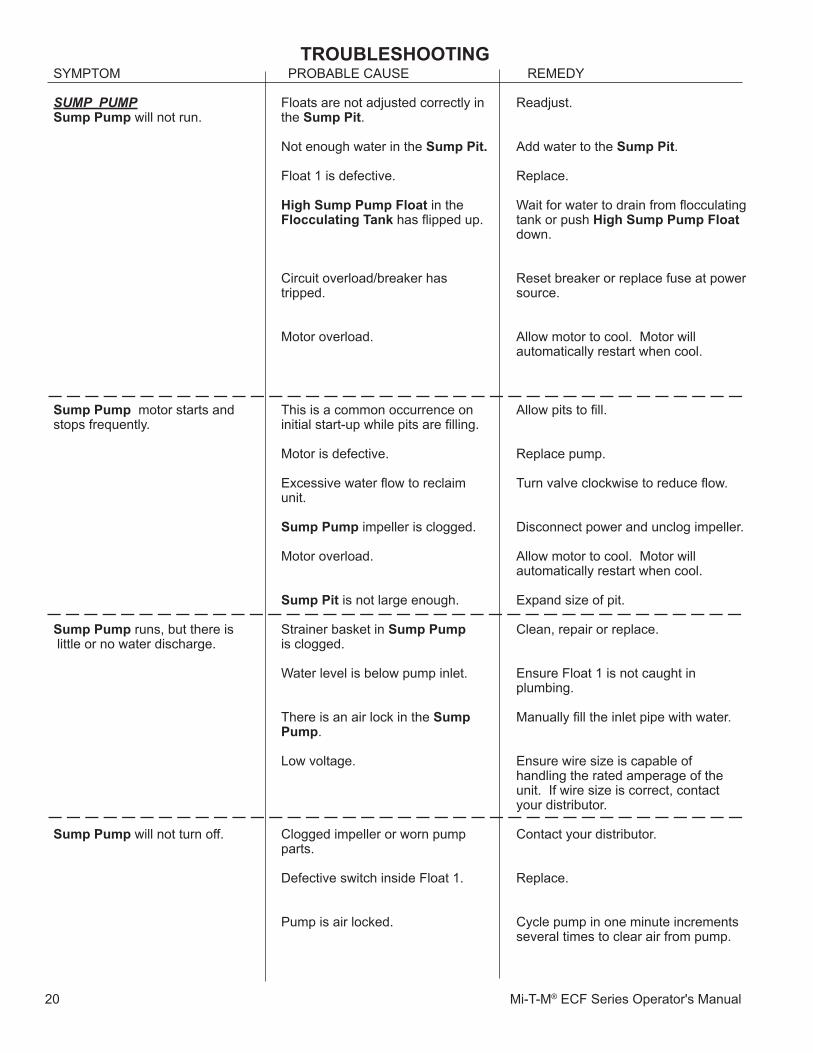
TROUBlesHOOTINgSYMPTOM PROBABLE CAUSE REMEDY
Floats are not adjusted correctly in the sump.pit.
Not enough water in the sump.pit.
Float � is defective. High.sump.pump.float in the flocculating.Tank.has flipped up.
Circuit overload/breaker has tripped.
Motor overload.
This is a common occurrence on initial start-up while pits are filling.
Motor is defective.
Excessive water flow to reclaim unit.
sump.pump impeller is clogged.
Motor overload.
sump.pit is not large enough.
Strainer basket in sump.pump.is clogged.
Water level is below pump inlet.
There is an air lock in the sump pump.
Low voltage.
Clogged impeller or worn pump parts.
Defective switch inside Float �.
Pump is air locked.
sUmp pUmp sump.pump will not run.
sump.pump. motor starts and stops frequently.
sump.pump runs, but there is little or no water discharge.
sump.pump will not turn off.
Readjust.
Add water to the sump.pit.
Replace. Wait for water to drain from flocculating tank or push High.sump.pump.float down. Reset breaker or replace fuse at power source.
Allow motor to cool. Motor will automatically restart when cool.
Allow pits to fill.
Replace pump.
Turn valve clockwise to reduce flow.
Disconnect power and unclog impeller. Allow motor to cool. Motor will automatically restart when cool.
Expand size of pit.
Clean, repair or replace.
Ensure Float � is not caught in plumbing.
Manually fill the inlet pipe with water.
Ensure wire size is capable of handling the rated amperage of the unit. If wire size is correct, contact your distributor.
Contact your distributor.
Replace.
Cycle pump in one minute increments several times to clear air from pump.
Mi-T-M ECF Series Operator's Manual 2�
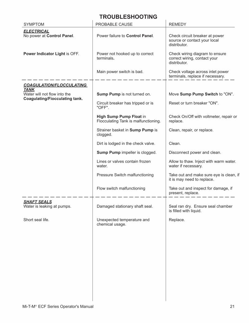
SYMPTOM PROBABLE CAUSE REMEDY
TROUBlesHOOTINg
Check circuit breaker at power source or contact your local distributor. Check wiring diagram to ensure correct wiring, contact your distributor.
Check voltage across inlet power terminals, replace if necessary.
Move sump.pump.switch.to "ON".
Reset or turn breaker "ON".
Check On/Off with voltmeter, repair or replace.
Clean, repair, or replace.
Clean.
Disconnect power and clean.
Allow to thaw. Inject with warm water. water if necessary.
Take out and make sure eye is clean, if it is may need to replace.
Take out and inspect for damage, if present, replace.
Seal ran dry. Ensure seal chamber is filled with liquid.
Replace.
Power failure to Control.panel.
Power not hooked up to correct terminals.
Main power switch is bad.
sump.pump is not turned on.
Circuit breaker has tripped or is "OFF".
High.sump.pump.float in Flocculating Tank is malfunctioning. Strainer basket in sump.pump is clogged. Dirt is lodged in the check valve. sump.pump impeller is clogged. Lines or valves contain frozen water.
Pressure Switch malfunctioning
Flow switch malfunctioning
Damaged stationary shaft seal.
Unexpected temperature and chemical usage.
ElECTRICAlNo power at Control.panel.
power.Indicator.light is OFF.
COAGUlATION/flOCCUlATING TANk Water will not flow into the Coagulating/fiocculating.tank.
shAfT sEAls Water is leaking at pumps.
Short seal life.
22 Mi-T-M® ECF Series Operator's Manual
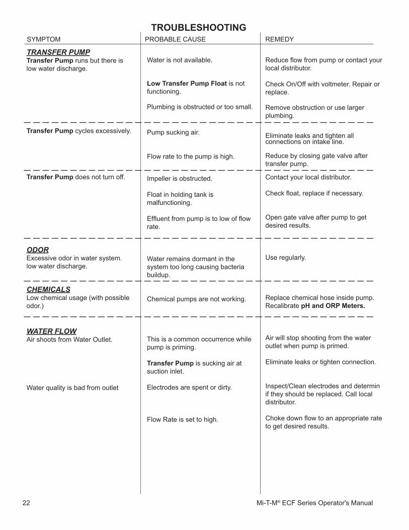
TROUBlesHOOTINgSYMPTOM PROBABLE CAUSE REMEDY
Reduce flow from pump or contact your local distributor.
Check On/Off with voltmeter. Repair or replace.
Remove obstruction or use larger plumbing.
Eliminate leaks and tighten all connections on intake line.
Reduce by closing gate valve after transfer pump.
Contact your local distributor.
Check float, replace if necessary.
Open gate valve after pump to get desired results.
Use regularly.
Replace chemical hose inside pump.Recalibrate pH.and.ORp.meters.
Air will stop shooting from the wateroutlet when pump is primed.
Eliminate leaks or tighten connection.
Inspect/Clean electrodes and determin if they should be replaced. Call local distributor.
Choke down flow to an appropriate rate to get desired results.
Water is not available.
low.Transfer.pump.float is notfunctioning.
Plumbing is obstructed or too small.
Pump sucking air.
Flow rate to the pump is high.
Impeller is obstructed.
Float in holding tank is malfunctioning.
Effluent from pump is to low of flow rate.
Water remains dormant in the system too long causing bacteria buildup.
Chemical pumps are not working.
This is a common occurrence whilepump is priming.
Transfer.pump is sucking air at suction inlet.
Electrodes are spent or dirty.
Flow Rate is set to high.
TRANsfER pUmpTransfer.pump runs but there islow water discharge.
Transfer.pump cycles excessively.
Transfer.pump does not turn off.
ODORExcessive odor in water system.low water discharge.
ChEmICAlsLow chemical usage (with possible odor.)
WATER flOWAir shoots from Water Outlet.
Water quality is bad from outlet
Mi-T-M ECF Series Operator's Manual 23
sTaTemeNT.Of.WaRRaNTy
Mi-T-M warrants all parts (except those referred to below) of your new Electrocoagulation System to be free from defects in materials and workmanship during the following periods:
For One (�) Year from the date of original purchase:Defective parts not subject to normal wear and tear will be repaired or replaced at Mi-T-M's option during the warranty period. In any event, reimbursement is limited to the purchase price paid.
eXClUsIONs
�. The motor is covered under separate warranty by its respective manufacturer and is subject to the terms set forth therein.
2. Normal wear parts: Seals Filters Gaskets O-rings Packings Valve Assembly Brushes 3. Parts damaged due to: -normal wear, misapplication, modifications/alterations, abuse, -operation at other than recommended speeds, pressures or temperature, -the use of caustic liquids, -chloride corrosion or chemical deterioration, -fluctuations in electrical or water supply, -operating unit in an abrasive, corrosive or freezing environment.
4. Parts damaged by failure to follow recommended: -installation, operating and maintenance procedures.
5. This warranty does not cover the cost of: -normal maintenance or adjustments, -labor charges, -transportation charges to Service Center, -freight damage. 6. The use of other than genuine Mi-T-M parts will void warranty.
Parts returned, prepaid to Mi-T-M's factory or to an Authorized Service Center will be inspected and replaced free of charge if found to be defective and subject to warranty. There are no warranties which extend beyond the description of the face hereof. Under no circumstances shall Mi-T-M bear any responsibility for loss of use of the unit, loss of time or rental, inconvenience, commercial loss or consequential damages.

24 Mi-T-M® ECF Series Operator's Manual
Manufactured by Mi-T-M8650 Enterprise Drive, Peosta IA 52068
563-556-7484/ Fax 563-556-1235