Embed Size (px)
Citation preview
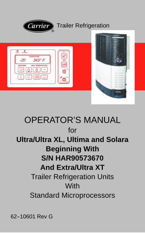
OPERATOR’S MANUALfor
Ultra/Ultra XL, Ultima and SolaraBeginning With
S/N HAR90573670And Extra/Ultra XT
Trailer Refrigeration UnitsWith
Standard Microprocessors
62--10601 Rev G
Trailer Refrigeration
FAULT
START/STOP
FUNCTION
CHANGE
UNIT
DATA
PRETRIP
CHECK
AUTO S/S
CONTINUOUS
MANUAL
DEFROST
ENTER
SETPOINT BOX TEMPERATURE
-20 34.5° F
STANDBYFAULT
STANDBYPOWER ON
1
0
START/RUN
OFF
STANDBY
ENGINE
R

MANUALfor
OPERATOR’S
TRAILERREFRIGERATION UNITS
WITH STANDARDMICROPROCESSOR

CONTENTS
Page
Safety 1. . . . . . . . . . . . . . . . . . . . . . . . . . . . . . . . . . . .
Unit Identification 2. . . . . . . . . . . . . . . . . . . . . . . . . .
Unit Operation 4. . . . . . . . . . . . . . . . . . . . . . . . . . . .
Starting Unit 4. . . . . . . . . . . . . . . . . . . . . . . . . . . . . .
Pretrip Check 8. . . . . . . . . . . . . . . . . . . . . . . . . . . . .
Changing Setpoint 10. . . . . . . . . . . . . . . . . . . . . . . .
Start--Stop Operation 12. . . . . . . . . . . . . . . . . . . . . .
Continuous Run Operation 14. . . . . . . . . . . . . . . . .
Manual Defrost 16. . . . . . . . . . . . . . . . . . . . . . . . . . .
Function Change 18. . . . . . . . . . . . . . . . . . . . . . . . .
Unit Data 20. . . . . . . . . . . . . . . . . . . . . . . . . . . . . . . .
Alarm Display and Reset 22. . . . . . . . . . . . . . . . . .
Standby Operation 24. . . . . . . . . . . . . . . . . . . . . . . .
Stopping Unit 26. . . . . . . . . . . . . . . . . . . . . . . . . . . .
Pre--Trip Inspection 28. . . . . . . . . . . . . . . . . . . . . . .
Product Loading 30. . . . . . . . . . . . . . . . . . . . . . . . . .
Recommended Transport Temperatures 32. . . . .
Problems 33. . . . . . . . . . . . . . . . . . . . . . . . . . . . . . . .
Fuses 34. . . . . . . . . . . . . . . . . . . . . . . . . . . . . . . . . . .
Unit Maintenance 35. . . . . . . . . . . . . . . . . . . . . . . . .
Unit Maintenance Schedule 36. . . . . . . . . . . . . . . .
Priming Fuel System 39. . . . . . . . . . . . . . . . . . . . . .
Emergency Road Service 40. . . . . . . . . . . . . . . . . .

1 62--10601
SAFETY
Your Carrier Transicold refrigeration unit has been designed withthe safety of the operator in mind. During all pre-trip inspections,daily inspections, and problem troubleshooting, you may beexposed to moving parts; please stay clear of all moving parts whenthe unit is in operation and when the Start/Run-Off Switch is in theSTART/RUN position.
AUTO-STARTYour refrigeration unit is equipped with Auto-Start in both Start/Stopand Continuous Run modes. The unit may start at any time, abuzzer will sound for 5 seconds before the unit is started. Whenperforming any check of the refrigeration unit (e.g., checking thebelts, checking the oil), make certain that the Start/Run-Off Switchis in the OFF position.
ENGINE COOLANTThe engine is equipped with a pressurized cooling system. Undernormal operating conditions, the coolant in the engine and radiatoris under high pressure and is very hot. Contact with hot coolant cancause severe burns. Do not remove the cap from a hot radiator; ifthe cap must be removed, do so very slowly in order to release thepressure without spray.
REFRIGERANTSThe refrigerant contained in the refrigeration system of your unitcan cause frostbite, severe burns, or blindness when in directcontact with the skin or eyes. For this reason, and because oflegislation regarding the handling of refrigerants during systemservice, we recommend that, whenever your unit requires serviceof the refrigeration system, you contact your nearest CarrierTransicold authorized repair facility for service.
BATTERYThis unit is equipped with a lead-acid type battery. The batterynormally vents small amounts of flammable hydrogen gas. Do notsmoke when checking the battery. A battery explosion can causeserious physical harm and/or blindness.

262--10601
UNIT IDENTIFICATION
Each unit is identified by a decal attached to the frame of the unit.This decal is on the roadside vertical frame post behind theroadside side door. This decal identifies the complete modelnumber of the unit, the serial number, the refrigerant charge andquantity, and the date the unit was placed in service.
If a problem occurs, please refer to the information on this decal,and make a note of the model and serial number before calling forassistance. This information will be needed when you contact atechnician or Carrier Transicold Service Engineer so that they mayproperly assist you.

3 62--10601
UnitIdentificationDecal
462--10601
UNIT OPERATION
STARTING UNIT - AUTO
FAULT STAND-BY
START/STOP
FUNCTIONCHANGE
UNITDATA
PRETRIPCHECK
AUTO S/SCONTINUOUS
MANUALDEFROST
ENTER
SETPOINT BOX TEMPERATURE
FAULT
STANDBYPOWER ON
1
0
START/RUN
OFF
STANDBY
ENGINE
888888888888888888888888888888888888****
FAULT STAND-BY
START/STOP
FUNCTIONCHANGE
UNITDATA
PRETRIPCHECK
AUTO S/SCONTINUOUS
MANUALDEFROST
ENTER
SETPOINT BOX TEMPERATURE
FAULT
STANDBYPOWER ON
1
0
START/RUN
OFF
STANDBY
ENGINE
----22220000....0000 33334444....5555°°°° FFFF
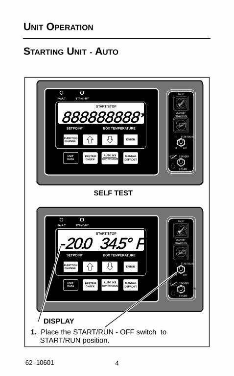
1. Place the START/RUN - OFF switch toSTART/RUN position.
DISPLAY
SELF TEST
5 62--10601
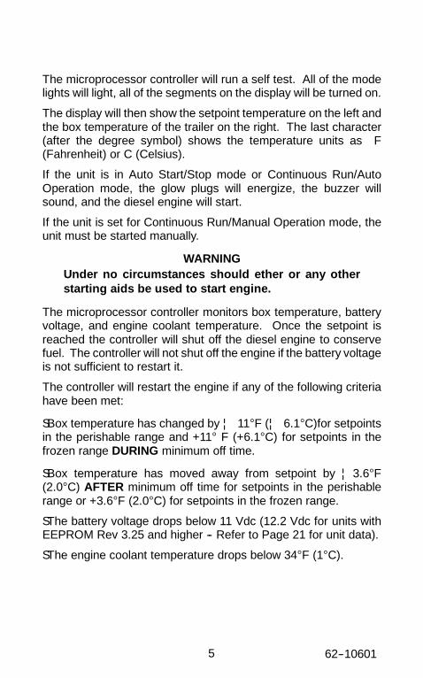
The microprocessor controller will run a self test. All of the modelights will light, all of the segments on the display will be turned on.
The display will then show the setpoint temperature on the left andthe box temperature of the trailer on the right. The last character(after the degree symbol) shows the temperature units as F(Fahrenheit) or C (Celsius).
If the unit is in Auto Start/Stop mode or Continuous Run/AutoOperation mode, the glow plugs will energize, the buzzer willsound, and the diesel engine will start.
If the unit is set for Continuous Run/Manual Operation mode, theunit must be started manually.
WARNINGUnder no circumstances should ether or any otherstarting aids be used to start engine.
The microprocessor controller monitors box temperature, batteryvoltage, and engine coolant temperature. Once the setpoint isreached the controller will shut off the diesel engine to conservefuel. The controller will not shut off the engine if the battery voltageis not sufficient to restart it.
The controller will restart the engine if any of the following criteriahave been met:
SBox temperature has changed by ¦ 11°F (¦ 6.1°C)for setpointsin the perishable range and +11° F (+6.1°C) for setpoints in thefrozen range DURING minimum off time.
SBox temperature has moved away from setpoint by ¦3.6°F(2.0°C) AFTER minimum off time for setpoints in the perishablerange or +3.6°F (2.0°C) for setpoints in the frozen range.
SThe battery voltage drops below 11 Vdc (12.2 Vdc for units withEEPROM Rev 3.25 and higher -- Refer to Page 21 for unit data).
SThe engine coolant temperature drops below 34°F (1°C).

662--10601
STARTING UNIT - MANUAL (CONTINUOUS RUN ONLY)
FAULT STAND-BY
FUNCTIONCHANGE
UNITDATA
PRETRIPCHECK
AUTO S/SCONTINUOUS
MANUALDEFROST
ENTER
SETPOINT BOX TEMPERATURE
FAULT
STANDBYPOWER ON
1
0
START/RUN
OFF
STANDBY
ENGINE
MMMMAAAANNNN OOOOPPPP
Side of Control Box
4. Hold GLOW/CRANK switch in the GLOW position for5 to 15 seconds (see chart on next page). Then holdthe GLOW/CRANK switch in the CRANK position forup to 10 seconds to start the diesel engine.
1. Place START/RUN - OFF switch to the START/RUNposition. If START/STOP is displayed, press AUTOS/S-CONTINUOUS toggle key to place unit in ContinuousRun Mode .
2. Press FUNCTION CHANGE key until AUTO OP orMAN OP is displayed. If MAN OP appears, unit is inmanual start mode.
3. If AUTO OP appears, first press ENTER key, thenUP or DOWN arrow key until MAN OP is displayed.Press ENTER key to lock in manual mode.
5. With MAN OP selected, pressAUTO S/S-CONTINUOUS keyto toggle between AutoStart-Stop and ManualStart/Continuous Run modes.

7 62--10601
Glow TimeEngine Coolant Temperature Glow Time in Seconds
Engine Coolant Temperature TV/Short(Default)
DI/Long
Less than 32_F (0_C) 15 5533_F to 50_F (1_C to 10_C) 10 4051_F to 77_F (11_C to 25_C) 5 25Greater than 78_F (26_C) 0 10
NOTE: When the unit is in Continuous Run mode and setfor Manual Operation, the unit must be started manually
WARNINGUnder no circumstances should ether or any otherstarting aids be used to start engine.

862--10601
PRETRIP CHECK 1.
FAULT STAND-BY
COOL
FUNCTIONCHANGE
UNITDATA
PRETRIPCHECK
AUTO S/SCONTINUOUS
MANUALDEFROST
ENTER
SETPOINT BOX TEMPERATURE
FAULT
STANDBYPOWER ON
1
0
START/RUN
OFF
STANDBY
ENGINE
PPPPPPPPPPPPPPPP
2. Press PRETRIP CHECK key to startPRETRIP. “PPPP” will appear on the display.
1. Start and run unit until boxtemperature is 40_F (4.4°C) orlower.

9 62--10601
The PRETRIP mode is for checking unit operation and evaluatingoperation of all modes. The unit will cycle thru all modes ofoperation at 30 second intervals. When Pretrip is complete, Pretripmode is terminated and the unit returns to normal operation.
The final PRETRIP mode is Defrost. When Defrost ends,PRETRIP will be complete.
This is not a self-diagnosing pretrip test. No specific pretrip alarmswill be generated. Pretrip must be monitored by the user to verifythat the unit operates through all cycles.
See Page 28 for more information on Pretrip.

1062--10601
CHANGING SETPOINT
FAULT STAND-BY
FUNCTIONCHANGE
UNITDATA
PRETRIPCHECK
AUTO S/SCONTINUOUS
MANUALDEFROST
ENTER
SETPOINT BOX TEMPERATURE
FAULT
STANDBYPOWER ON
1
0
START/RUN
OFF
STANDBY
ENGINE
----22220000....0000 33334444....5555°°°° FFFF
Press ENTER key when desired setpoint isdisplayed to lock in new setpoint.
New setpoint will flash and then return to originalsetpoint if ENTER key is not pressed.
Press UP arrow key to increase displayedsetpoint.
Press DOWN arrow key to decreasedisplayed setpoint.

11 62--10601
Setpoints of -22°F to +89°F (-30°C to +32°C) may be entered viathe keypad. The controller always retains the last entered setpointin memory. If no setpoint is in memory (i.e. on initial startup), thecontroller will lock out the run relay and flash “SP” on the left handdisplay until a valid setpoint is entered. The setpoint may bechanged up or down in 1° increments by pressing and releasingeither the UP ARROW or DOWN ARROW key.
You can not change setpoint when unit is in Pretrip or when viewingUnit Data or Functional Parameters.
Pressing the ENTER key will cause the new displayed setpointvalue to become active. If the display is flashing and the new valueis not entered, after 5 seconds of no keyboard activity, the displaywill flash for 5 seconds and then revert back to the last setpoint.All other keys are active at this time and may be pushed while thedisplay is flashing.

1262--10601
START-STOP OPERATION
FAULT STAND-BY
START/STOP
FUNCTIONCHANGE
UNITDATA
PRETRIPCHECK
AUTO S/SCONTINUOUS
MANUALDEFROST
ENTER
SETPOINT BOX TEMPERATURE
FAULT
STANDBYPOWER ON
1
0
START/RUN
OFF
STANDBY
ENGINE
----22220000....0000 33334444....5555°°°° FFFF
1. Press the AUTO S/S-CONTINUOUStoggle key until START-STOP isdisplayed. Unit is now in AutomaticStart/Stop mode.
START/STOP
Automatic start/stop is provided to permit starting/restarting of thediesel-driven compressor as required. This gives themicroprocessor automatic control of starting and stopping thediesel engine. The main function of automatic start-stop is to turnoff the refrigeration system near the setpoint to provide a fuelefficient temperature control system and then restart the enginewhen needed. Start-Stop operation is normally used for frozenloads. Refer to RECOMMENDED TRANSPORT TEMPERATURES (See Page32).
13 62--10601
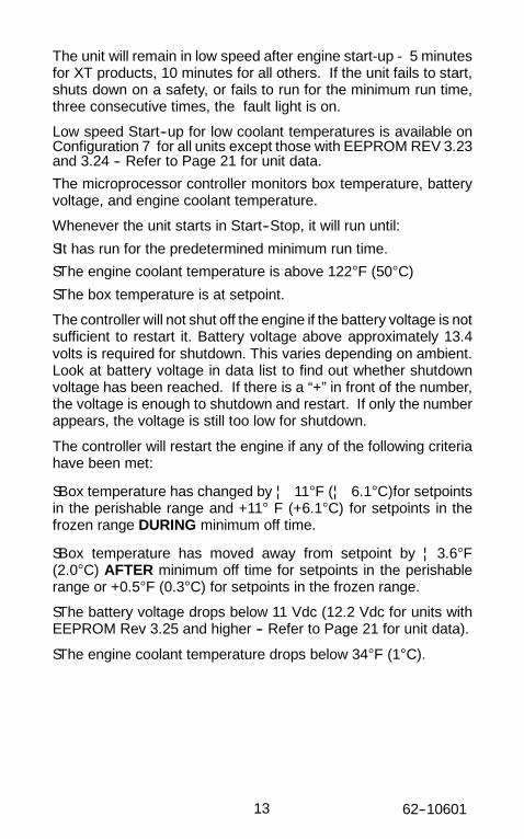
The unit will remain in low speed after engine start-up - 5 minutesfor XT products, 10 minutes for all others. If the unit fails to start,shuts down on a safety, or fails to run for the minimum run time,three consecutive times, the fault light is on.
Low speed Start--up for low coolant temperatures is available onConfiguration 7 for all units except those with EEPROM REV 3.23and 3.24 -- Refer to Page 21 for unit data.
The microprocessor controller monitors box temperature, batteryvoltage, and engine coolant temperature.
Whenever the unit starts in Start--Stop, it will run until:
SIt has run for the predetermined minimum run time.
SThe engine coolant temperature is above 122°F (50°C)
SThe box temperature is at setpoint.
The controller will not shut off the engine if the battery voltage is notsufficient to restart it. Battery voltage above approximately 13.4volts is required for shutdown. This varies depending on ambient.Look at battery voltage in data list to find out whether shutdownvoltage has been reached. If there is a “+” in front of the number,the voltage is enough to shutdown and restart. If only the numberappears, the voltage is still too low for shutdown.
The controller will restart the engine if any of the following criteriahave been met:
SBox temperature has changed by ¦ 11°F (¦ 6.1°C)for setpointsin the perishable range and +11° F (+6.1°C) for setpoints in thefrozen range DURING minimum off time.
SBox temperature has moved away from setpoint by ¦3.6°F(2.0°C) AFTER minimum off time for setpoints in the perishablerange or +0.5°F (0.3°C) for setpoints in the frozen range.
SThe battery voltage drops below 11 Vdc (12.2 Vdc for units withEEPROM Rev 3.25 and higher -- Refer to Page 21 for unit data).
SThe engine coolant temperature drops below 34°F (1°C).

1462--10601
CONTINUOUS RUN OPERATION
FAULT STAND-BY
FUNCTIONCHANGE
UNITDATA
PRETRIPCHECK
AUTO S/SCONTINUOUS
MANUALDEFROST
ENTER
SETPOINT BOX TEMPERATURE
FAULT
STANDBYPOWER ON
1
0
START/RUN
OFF
STANDBY
ENGINE
----22220000....0000 33334444....5555°°°° FFFF
START/STOP Must Not Be Displayed
1. Check if START-STOP is displayed. If itis, press the AUTO S/S-CONTINUOUStoggle key to place unit in ContinuousRun mode.

15 62--10601
In the Continuous Run mode, the diesel engine will runcontinuously providing constant air flow and temperature control tothe product. Continuous Run operation is normally used forperishable loads. Refer to RECOMMENDED TRANSPORT TEMPERATURES
(See Page 32).
Start-Stop and Continuous operation may be tied to the setpointranges for frozen and perishable loads and theSTART-STOP/CONTINUOUS key may be locked out.
The unit will remain in low speed - 5 minutes for XT products, 10minutes for all others, after engine start-up when the ContinuousRun setpoint is below 10°F (-12°C).
1662--10601
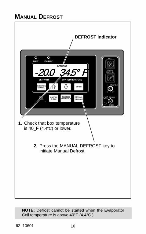
MANUAL DEFROST
FAULT STAND-BY
DEFROST
FUNCTIONCHANGE
UNITDATA
PRETRIPCHECK
AUTO S/SCONTINUOUS
MANUALDEFROST
ENTER
SETPOINT BOX TEMPERATURE
FAULT
STANDBYPOWER ON
1
0
START/RUN
OFF
STANDBY
ENGINE
----22220000....0000 33334444....5555°°°° FFFF
DEFROST Indicator
2. Press the MANUAL DEFROST key toinitiate Manual Defrost.
1. Check that box temperatureis 40_F (4.4°C) or lower.
NOTE: Defrost cannot be started when the EvaporatorCoil temperature is above 40°F (4.4°C ).
17 62--10601
The defrost mode may be initiated in three different ways if theevaporator coil is below 40°F (4.4°C):
1. Defrost is initiated automatically at preset intervals by thedefrost timer in the microprocessor.
2. Defrost is initiated by the defrost air switch.
3. The defrost mode may be manually initiated by pressing theManual Defrost Key.
The defrost mode terminates when the evaporator temperature ishigher than 55°F (12.8°C). Should the defrost cycle not completewithin 45 minutes, the defrost cycle is terminated.
After the 45 minute termination, the controller will wait 1.5 hoursbefore attempting another defrost cycle. Pressing the manualdefrost key will override this mode and start a defrost cycle.
If a shutdown alarm occurs, defrost will be terminated.

1862--10601
FUNCTION CHANGE (PARAMETERS)
FAULT STAND-BY
DEFROST
FUNCTIONCHANGE
UNITDATA
PRETRIPCHECK
AUTO S/SCONTINUOUS
MANUALDEFROST
ENTER
SETPOINT BOX TEMPERATURE
FAULT
STANDBYPOWER ON
1
0
START/RUN
OFF
STANDBY
ENGINE
2. Press ENTER key.
3. Press either ↑ UP or ↓ DOWN ARROW keyuntil desired Function setting is displayed.
4. Press the ENTER key to lock in new setting.
1. Press FUNCTION CHANGE key untilFunction to be changed is displayed.
DDDDEEEEFFFFRRRR 11112222....0000HHHH
NOTE: Function changes will change operationof unit.
NOTE: If configuration CNF11 is “ON”functional parameters are locked.The ability to change any functionalparameters is disabled.

19 62--10601
FUNCTION CHANGE (PARAMETERS)The following table has columns for Code and English displays.English is the default setting. Change Functional Parameter toCode to see Code display format.
Function CodesCODE ENGLISH DATA
FN0 DEFR Defrost Time IntervalFN1 ON HIGH AIR High Air FlowFN1 OFF NORM AIR Normal Air FlowFN2 OFF T Minimum Off-timeFN3 ON T Minimum On-time
FN4 A REMPROBE
Controlling Probe -Return Air
FN4 B SUPPROBE
Dual Controlling Probe -Return and Supply Air
FN5 DegreesF or C
Temperature UnitDisplayed in _C or _F
FN6 ON TIMESTRT Maximum Off-Time 30 Min
FN6 OFF
TEMPSTRT
Temperature and MinimumOff-Time BasedRestarting For AutoStart/Stop
FN7 MOP STD Unloader ControlFN10 ON AUTO OP Auto Start OperationFN10 OFF MAN OP Manual Start OperationFN11 T RANGE Out-of-Range ToleranceCode vs English = Code or English display formatManual Glow Override = Normal or Add 30secAlarm Reset = Alarm Reset or No Alarms

2062--10601
UNIT DATA
FAULT STAND-BY
COOL
FUNCTIONCHANGE
UNITDATA
PRETRIPCHECK
AUTO S/SCONTINUOUS
MANUALDEFROST
ENTER
SETPOINT BOX TEMPERATURE
FAULT
STANDBYPOWER ON
1
0
START/RUN
OFF
STANDBY
ENGINE
ssssuuuucccctttt 22225555PPPP
2. To scroll through the list faster,use the UP or DOWNARROW keys.
4. Press the ENTER key todisplay data for 30 seconds.
1. Press UNIT DATA key toscroll thru data list one itemat a time.
3. Data will display for 5 seconds

21 62--10601
UNIT DATAThe following table has columns for Code and English displays.English is the default setting. Change Functional Parameter toCode to see Code display format.
Unit Data CodesCODE ENGLISH DATACD1 SUCT Suction PressureCD2 ENG Engine HoursCD3 WT CoolantTemperatureCD4 RAS Return Air Temperature*CD5 SAS Supply Air Temperature*CD6 REM Remote Air TemperatureCD7 ATS Ambient Air TemperatureCD8 ------ Door Open/ClosedCD9 CDT Discharge Temperature
CD10 BATT Battery VoltageCD11 SBY Standby HoursCD12 MOD V Future ExpansionCD13 REV Software RevisionCD14 SERL Serial Number LowerCD15 SERU Serial Number UpperCD18 MHR1 Maintenance Hour Meter 1CD19 MHR2 Maintenance Hour Meter 2CD20 SON Switch On Hour Meter
* Codes 5 & 6 are variable. SAS is displayed whenthe SUP Probe Function is selected. REM is dis-played when the REM Probe Function is selected.(See Functional Parameter List on Page 19.)

2262--10601
ALARM DISPLAY & RESET
ALARM DISPLAYWhen an alarm is on, normal display of Setpoint/Box Temperaturealternates with alarm display.When fault light is on, check display for alarm message.
ALARM RESET
FAULT STAND-BY
COOL
FUNCTIONCHANGE
UNITDATA
PRETRIPCHECK
AUTO S/SCONTINUOUS
MANUALDEFROST
ENTER
SETPOINT BOX TEMPERATURE
FAULT
STANDBYPOWER ON
1
0
START/RUN
OFF
STANDBY
ENGINE
EEEENNNNGGGG OOOOIIIILLLL
1. Press FUNCTION CHANGE key.
3. Press ENTER to clear alarm. ALARMCLR will be displayed. (Unit will restart ifalarm condition has been corrected andunit is in Start/Stop or Auto OP).
2. Press UP/DOWN arrowkey until ALARM RSTis displayed.
FAULT LIGHT
ALTERNATE ALARM RESETPlace START/RUN-OFF switch to OFF position. (Unit can now berestarted after alarm condition has been corrected).
23 62--10601
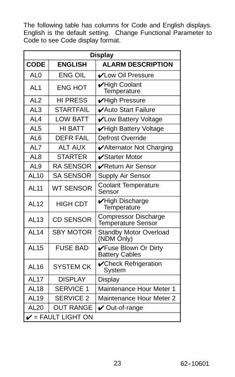
The following table has columns for Code and English displays.English is the default setting. Change Functional Parameter toCode to see Code display format.
DisplayCODE ENGLISH ALARM DESCRIPTION
AL0 ENG OIL ✔ Low Oil Pressure
AL1 ENG HOT ✔ High CoolantTemperature
AL2 HI PRESS ✔ High PressureAL3 STARTFAIL ✔ Auto Start FailureAL4 LOW BATT ✔ Low Battery VoltageAL5 HI BATT ✔ High Battery VoltageAL6 DEFR FAIL Defrost OverrideAL7 ALT AUX ✔ Alternator Not ChargingAL8 STARTER ✔ Starter MotorAL9 RA SENSOR ✔ Return Air SensorAL10 SA SENSOR Supply Air Sensor
AL11 WT SENSOR Coolant TemperatureSensor
AL12 HIGH CDT ✔ High DischargeTemperature
AL13 CD SENSOR Compressor DischargeTemperature Sensor
AL14 SBY MOTOR Standby Motor Overload(NDM Only)
AL15 FUSE BAD ✔ Fuse Blown Or DirtyBattery Cables
AL16 SYSTEM CK ✔ Check RefrigerationSystem
AL17 DISPLAY DisplayAL18 SERVICE 1 Maintenance Hour Meter 1AL19 SERVICE 2 Maintenance Hour Meter 2AL20 OUT RANGE ✔ Out-of-range
✔ = FAULT LIGHT ON

2462--10601
STANDBY OPERATION
FAULT STAND-BY
COOL
FUNCTIONCHANGE
UNITDATA
PRETRIPCHECK
AUTO S/SCONTINUOUS
MANUALDEFROST
ENTER
SETPOINT BOX TEMPERATURE
----22220000....0000 33334444....5555°°°° FFFF
3. Place ENGINE/STANDBY switch inSTANDBY position.
2. Plug in power supply.
1. Place START/RUN-OFF switch in OFFposition
For units equipped with electric standby:
4. Place START/RUN-OFF switch in START/RUNposition.
FAULT
STANDBYPOWER ON
1
0
START/RUN
OFF
STANDBY
ENGINE
WARNINGMake sure the power plugs areclean and dry before connec-tor to any power receptacle.

25 62--10601
Standby Operation is for Ultra NDM units only.
Check for proper motor rotation. Condenser air must be drawn intounit. To reverse rotation, stop unit, disconnect power cord andchange polarity of plug.
2662--10601
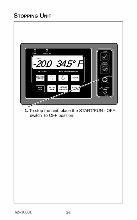
STOPPING UNIT
FAULT STAND-BY
FUNCTIONCHANGE
UNITDATA
PRETRIPCHECK
AUTO S/SCONTINUOUS
MANUALDEFROST
ENTER
SETPOINT BOX TEMPERATURE
FAULT
STANDBYPOWER ON
1
0
START/RUN
OFF
STANDBY
ENGINE
1. To stop the unit, place the START/RUN - OFFswitch to OFF position.
----22220000....0000 33334444....5555°°°° FFFFCOOL

27 62--10601
The diesel engine will stop and the microprocessor controller willturn off.
2862--10601
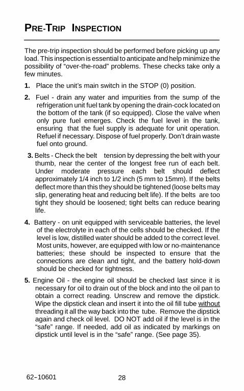
PRE-TRIP INSPECTION
The pre-trip inspection should be performed before picking up anyload. This inspection is essential to anticipate andhelp minimize thepossibility of “over-the-road” problems. These checks take only afew minutes.
1. Place the unit’s main switch in the STOP (0) position.
2. Fuel - drain any water and impurities from the sump of therefrigeration unit fuel tank by opening the drain-cock located onthe bottom of the tank (if so equipped). Close the valve whenonly pure fuel emerges. Check the fuel level in the tank,ensuring that the fuel supply is adequate for unit operation.Refuel if necessary. Dispose of fuel properly. Don’t drain wastefuel onto ground.
3. Belts - Check the belt tension by depressing the belt with yourthumb, near the center of the longest free run of each belt.Under moderate pressure each belt should deflectapproximately 1/4 inch to 1/2 inch (5 mm to 15mm). If the beltsdeflect more than this they should be tightened (loose belts mayslip, generating heat and reducing belt life). If the belts are tootight they should be loosened; tight belts can reduce bearinglife.
4. Battery - on unit equipped with serviceable batteries, the levelof the electrolyte in each of the cells should be checked. If thelevel is low, distilled water should be added to the correct level.Most units, however, are equipped with low or no-maintenancebatteries; these should be inspected to ensure that theconnections are clean and tight, and the battery hold-downshould be checked for tightness.
5. Engine Oil - the engine oil should be checked last since it isnecessary for oil to drain out of the block and into the oil pan toobtain a correct reading. Unscrew and remove the dipstick.Wipe the dipstick clean and insert it into the oil fill tube withoutthreading it all the way back into the tube. Remove the dipstickagain and check oil level. DO NOT add oil if the level is in the“safe” range. If needed, add oil as indicated by markings ondipstick until level is in the “safe” range. (See page 35).

29 62--10601
6. Over-all Unit - visually inspect the entire unit for leaks, loosebolts, frayed, loose, or broken wires, etc. Theradiator/condenser coils of the unit should be free of dirt, bugs,cardboard, or any other debris that may obstruct airflow acrossthe coils. The evaporator (located inside the trailer) should befree of debris also, especially stretch-wrap, which is often usedduring transport to prevent cargo shifting.
7. Start a Pretrip Check (See Page 8). The unit will cycle thru allmodes of operation at 30 second intervals, and return to normaloperation when complete. Monitor Pretrip and watch/listen forunusual operation or noises.

3062--10601
PRODUCT LOADING
BEFORE LOADING:
D Pre-cool the trailer. This will remove much of the heat from theinside of the trailer, and give the product better protection whenit is loaded.
D If possible, place the unit in a defrost cycle immediately beforeloading. This will remove moisture accumulated on theevaporator coil.
DURING LOADING:
D Turn the unit off!
D Check product temperature during loading.
D Ensure that the air return and supply opening remainunobstructed.
D Leave approximately 4 to 5 inches (10 to 12 cm) between theload and the front wall for air return to the unit.
D Leave at least 10 to 12 inches (25 to 30 cm) between the top ofthe load and the ceiling to ensure that there is nothing to preventairflow to the rear of the body
D Load product on pallets to provide free air return to unit andimprove product protection.
Proper air circulation in the trailer, air that can move around andthrough the load, is a critical element in maintaining product qualityduring transport. If air cannot circulate completely around the load,hot spots or top-freeze can occur.
The use of pallets is highly recommended. Pallets, when loaded soair can flow freely through the pallets to return to the evaporator, helpprotect the product from heat passing through the floor of the trailer.When using pallets, it is important to refrain from stacking extra boxeson the floor at the rear of the trailer, this will cut off the airflow.
31 62--10601
Product stacking is another important factor in protecting theproduct. Products that generate heat - fruits and vegetables, forexample - should be stacked so the air can flow through the productto remove the heat; this is called “air stacking” the product.Products that do not create heat - meats and frozen products -should be stacked tightly in the center of the trailer. All productsshould be kept away from the side-walls of the body, to allow air flowbetween the body and the load; this prevents heat filtering throughthe walls from affecting the product.
It is important to check the temperature of the product being loadedto ensure that it is at the correct temperature for transport. Therefrigeration unit is designed to maintain the temperature of theproduct at the temperature at which it was loaded; it was notdesigned to cool warm product.

3262--10601
RECOMMENDED TRANSPORT TEMPERATURES
Below are some general recommendations on product transporttemperatures and operating modes for the unit. These are includedfor reference only and should not be considered preemptive of thesetpoint required by the shipper or receiver.
More detailed information can be obtained from your CarrierTransicold dealer.
ProductSetpoint Range
Operating Mode1Product°°°°F °°°°C
Operating Mode1
Bananas 56 to 58 13 to 14 Continuous
Fresh fruits andvegetables
33 to 38 0.5 to 3 Continuous
Fresh meats andseafood
28 to 32 -2 to 0 Auto-Start/Stop orContinuous
Dairy Products 33 to 38 0.5 to 3 Auto-Start/Stop orContinuous
Ice 15 to 20 -10 to -7 Auto-Start/Stop2
Frozen fruits andvegetables
-10 to 0 -23 to -18 Auto-Start/Stop2
Frozen meats andseafood
-10 to 0 -23 to -18 Auto-Start/Stop2
Ice Cream -20 to -15 -29 to -26 Auto-Start/Stop2
1 During delivery cycles that include frequent stops and dooropenings, it is recommended that the unit always be operated in thecontinuous run mode to help insure product quality. If it is possible,the unit should be turned off during the time the trailer doors areopen to help conserve the product temperature.2 Variations may be necessary for very high or very low ambienttemperatures. 2.

33 62--10601
PROBLEMS
Everything possible has been done to ensure that your unit is themost reliable, trouble-free equipment available today. If, howeveryou run into problems the following section may be of assistance.
If you do not find the trouble that you have experienced listed,please call your Carrier Transicold dealer for assistance.
General ProblemsUnit won’t crank. Check battery condition.
Check battery connections.Check all fuses
Unit won’t start. Check fuel level.Check all fusesCheck fuel system for loss of prime (SeePage 39)
Unit won’t run. Check fuel level.Check engine oil level.Check all fuses
Unit stops operating. Check belts.Check engine oil level.Check coolant level.Check fuel level.Check all fuses.
Unit not cooling properly. Defrost unit.Check evaporator for airflow restriction.Check condenser for airflow restriction.Check body for damage or air leaks.
3462--10601
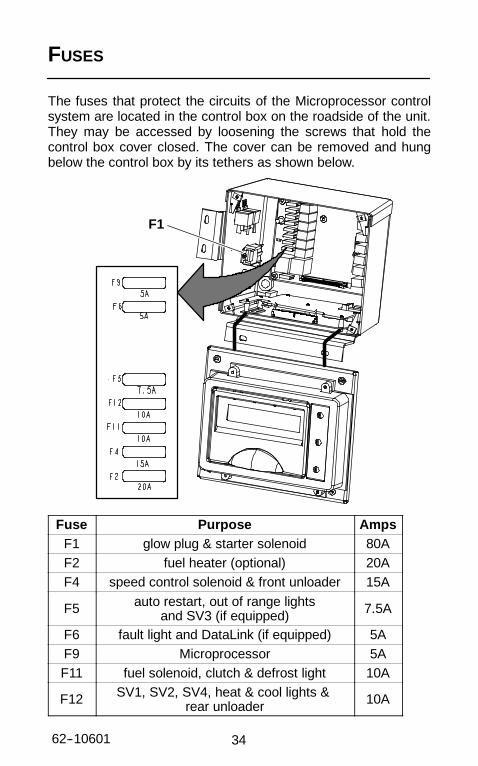
FUSES
The fuses that protect the circuits of the Microprocessor controlsystem are located in the control box on the roadside of the unit.They may be accessed by loosening the screws that hold thecontrol box cover closed. The cover can be removed and hungbelow the control box by its tethers as shown below.
F1
Fuse Purpose AmpsF1 glow plug & starter solenoid 80AF2 fuel heater (optional) 20AF4 speed control solenoid & front unloader 15A
F5 auto restart, out of range lightsand SV3 (if equipped) 7.5A
F6 fault light and DataLink (if equipped) 5AF9 Microprocessor 5AF11 fuel solenoid, clutch & defrost light 10A
F12 SV1, SV2, SV4, heat & cool lights &rear unloader 10A
35 62--10601
UNIT MAINTENANCE 3.
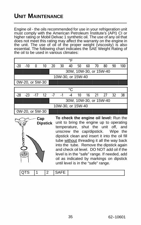
Engine oil - the oils recommended for use in your refrigeration unitmust comply with the American Petroleum Institute’s (API) CI orhigher rating or Mobil Delvac 1 synthetic oil. The use of any oil thatdoes not meet this rating may affect the warranty on the engine inthe unit. The use of oil of the proper weight (viscosity) is alsoessential. The following chart indicates the SAE Weight Rating ofthe oil to be used in various climates:
°F-20 -10 0 10 20 30 40 50 60 70 80 90 100
30W, 10W-30, or 15W-4010W-30, or 15W-40
0W-20, or 5W-30
°C-28 -23 -17 12 -7 -1 -4 10 16 21 27 32 38
30W, 10W-30, or 15W-4010W-30, or 15W-40
0W-20, or 5W-30
To check the engine oil level: Run theunit to bring the engine up to operatingtemperature, shut the unit off, andunscrew the cap/dipstick. Wipe thedipstick clean and insert it into the oil filltube without threading it all the way backinto the tube. Remove the dipstick againand check oil level. DO NOT add oil if thelevel is in the “safe” range. If needed, addoil as indicated by markings on dipstickuntil level is in the “safe” range.
QTS 1 2 SAFE
CapDipstick

3662--10601
UNIT MAINTENANCE SCHEDULE
For the most reliable operation and for maximum life, your unitrequires regular maintenance. This includes oil and filter changes,fuel and air filter replacement, coolant replacement. Maintenanceshould be performed on the following schedule:
SERVICE
Every 1500 Hours(TV engine)
Every 2000 Hours(DI engine)
Yearly(ALL engines)
D Drain the engine oil and replace oil filter.*D Check engine cooling system.D Check air cleaner.D Check all bolts, screws and unit mounting
bolts for tightness. Tighten as required.D Check all belts.D Replace fuel filter.D Clean fuel pump filter.D Check battery terminals and fluid level.D Check compressor oil level.D Check alternator brushes.D Check engine thermostat.D Check defrost:
- Check defrost air switch calibration- Check timer setting and function- Check refrigerant control valves- Defrost ends automatically- Water drains from evaporator
D Clean radiator/condenser.D Check engine speed under loadD Pre-Trip Inspection.
Every 3000 Hours D Check alternator.D Clean and adjust fuel injectors.D Clean crankcase breather.D Pre-Trip Inspection.
Every 6000 hours D Change anti-freeze.**D Check and adjust rocker arms.D Pre-Trip Inspection.

37 62--10601
*Engine Service InformationOil & Filter Change
IntervalEng.Type
Std. OilFilter
ESI OilFilter
APIClassCG orHigher
MobilDelvac1
30-00450-00 2000hrs/1yr
4000 hrs/2 yrs***
DI30-00463-00
3000hrs/
2 yrs.
4000 hrs/2 yrs
TV30-00450-00 1500
hrs/1 yr3000 hrs/2 yrs***
TV30-00463-00 3000 hrs/
2 yrs4000 hrs/2 yrs.
Cooling System Service Interval
Standard Coolant 6000 hrs/2yrs
Extended Life Cool-ant
12000 hrs/5yrs
Eng. Oil Type: API Class CI or higher or Mobil Delvac 1Engine OIl Viscosity: SAE 15W40 or 10W-30Engine Oil Capacity: 15 quartsEngine Coolant Mixture: 50/50Engine Coolant Capacity: 8 quarts
These maintenance schedules are based on the use of approvedoils and regular Pre-Trip inspections of the unit. Failure to follow therecommended maintenance schedule may affect the life andreliability of the refrigeration unit.
**12,000 hours with Texaco (Havoline) extended life coolant.***New oil filter required at 1 year interval.

3862--10601
In addition to the above service requirements please adhere to thefollowing:
S Non-synthetic engine oil should be changed at least onceper year and synthetic engine oil should be changed atleast once every 2 years, even if the engine has not runthe necessary number of hours.
S Standard coolant (anti-freeze) should be replaced everytwo years. Extended life coolant should be replaced everyfive years.
A more detailed description of service requirements andprocedures can be found in the Service and Operations Manual foryour unit. This manual may be obtained from any Carrier Transicolddealer.

39 62--10601
PRIMING FUEL SYSTEM
The mechanical fuel lift pump is mounted on the engine next to theinjection pump. This pump has a manual plunger for priming the fuelsystem when the fuel tank has been run dry.
To prime the fuel system, use the following steps:
1. Turn the bleed valve (Red) counter-clockwise until fullyopened.
2. Turn the top of the manual fuel pump plungercounter-clockwise to unlock it. S-L-O-W-L-Y (up/down onceper second) pump the manual plunger until positive pressure(resistance) is felt. This may take up to 200 strokes. This willindicate fuel flow.
3. Continue to pump S-L-O-W-L-Y (up/down once per second)approximately 100 more strokes to fill the filter and bleed the airout of the lines.
4. Start engine. It may be necessary to continue to pump until theengine starts.
5. Depress and turn the top of the manual plunger clockwise tolock in place.
6. When engine is running smoothly, turn bleed valve clockwiseuntil fully closed.
ManualFuel PumpPlunger
RedFuel BleedValve

4062--10601
EMERGENCY ROAD SERVICE
At Carrier Transicold we’re working hard to give you completeservice when and where you need it. That means a worldwidenetwork of dealers that offer 24-hour emergency service. Theseservice centers are manned by factory trained service personneland backed by extensive parts inventories that will assure you ofprompt repair.
Should you experience a unit problem with your refrigeration unitduring transit, follow your company’s emergency procedure orcontact the nearest Carrier Transicold service center. Consult theShortstop Service Centers directory to locate the service centernearest you. This directory may be obtained from your CarrierTransicold dealer.
SSSS If you are unable to reach a service center,call our 24-hour Action Line: (800)448-1661
When calling, please have the following information ready forfastest service:
S Your name, the name of your company, and your location.
S A telephone number where you can be called back.
S Refrigeration unit model number and serial number.
S Box temperature, setpoint and product.
Brief description of the problem you are having, and what you havealready done to correct the problem.
We will do everything we can to get your problem taken care of andget you back on the road.

2005 Carrier Corporation D Printed in U. S. A. 0505
Carrier Transicold Division,Carrier CorporationTruck/Trailer Products GroupP.O. Box 4805Syracuse, N.Y. 13221 U.S A
www.carrier.transicold.com
North AmericaCarrier Transicold700 Olympic DriveAthens, GA 30601 USATel: 1--706--546--6469Fax: 1--706--546--5207
Central Americaand MexicoEjercito Nacional No. 418Piso 9, Torre YumalCol. Chapultepec Morales11570 Mexico, D.F.Tel: (5255) 9126.0300Fax: (5255) 9126.0373
A member of the United Technologies Corporation family. Stock symbol UTX
CALIFORNIAProposition 65 Warning
Diesel engine exhaust and some of itsconstituents are known to the Stateof California to cause cancer, birth defects,and other reproductive harm.